

Page 1

SCITEX Dual Roll Kit
User’s guide
Page 2

© 2011 Hewlett-Packard Development
Company, L.P.
First edition
Legal notices
The information contained herein is subject
to change without notice.
The only warranties for HP Products and
services are set forth in the express warranty
statement accompanying such products and
services. Nothing herein should be
construed as constituting an additional
warranty. HP shall not be liable for technical
or editorial errors or omissions contained
herein.
Page 3

Table of contents
1 Introduction ...................................................................................................................... 1
Purpose .................................................................................................................................. 1
Main components .................................................................................................................... 1
Requirements ........................................................................................................................... 1
2 Use of the dual-roll spindle ............................................................................................... 2
Load rolls onto the spindle ......................................................................................................... 2
Load rolls into the printer ........................................................................................................... 5
3 Troubleshooting .............................................................................................................. 10
4 Specifications .................................................................................................................. 11
ENWW iii
Page 4

iv ENWW
Page 5

1 Introduction
Purpose
The purpose of this document is to describe how to install, use and troubleshoot the Dual Roll used in
the following Printers:
HP Scitex LX800 Printer (126-in)
●
HP Scitex LX820 Printer (126-in)
●
HP Scitex LX850 Printer (126-in)
●
HP Scitex LX600 Printer (104-in)
●
HP Designjet L65500 Printer (104-in)
●
Introduction
For information about using these printers, refer to the corresponding User Guide or Maintenance and
Troubleshooting Guide.
Main components
The Dual Roll Kit includes the following components.
Two dual-roll spindles, each including one differential hub
●
One pair of substrate edge holders
●
One Allen key
●
Requirements
Before using the Dual Roll Kit with an HP LX Designjet printer, you must check that the printer's firmware
and HP Internal Print Server software are up to date.
Go to
http://www.hp.com/ and click Support & Drivers > Download drivers and software
(and firmware), enter the product name, click the name of your operating system, and download the
latest firmware and the latest Internal Print Server, if you do not already have them.
ENWW
Purpose
1
Page 6
2 Use of the dual-roll spindle
Dual-roll spindle
Load rolls onto the spindle
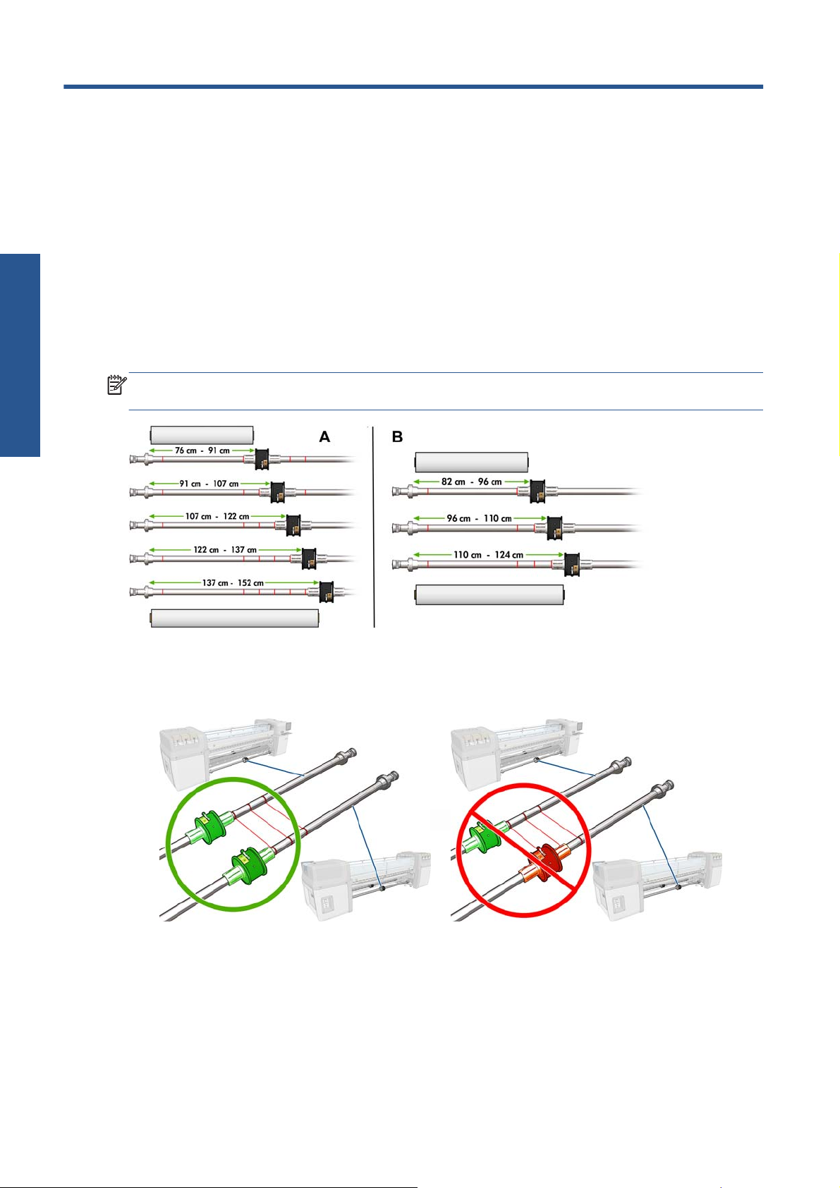
The dual-roll spindle is marked to assist you in positioning the differential hub.
NOTE: The spindle marked A is for the dimensions of the 126-in spindle. The spindle marked B is for
the dimensions of the 104-in spindle.
Loading the dual-roll spindles
1. Ensure that the differential hubs on the input and output spindles are aligned with each other.
2 Chapter 2 Use of the dual-roll spindle ENWW
Page 7

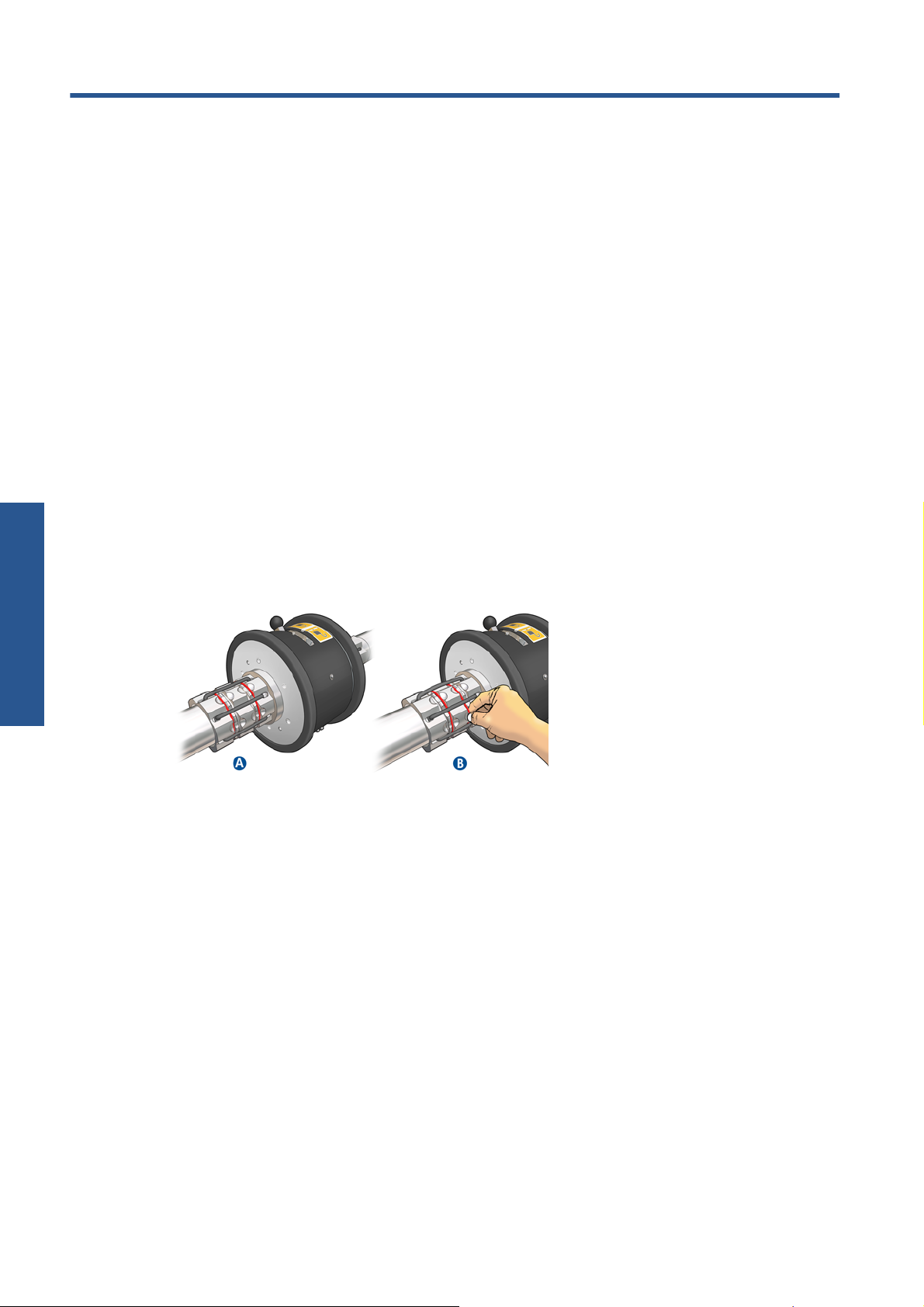
2. When both differential hubs are correctly positioned, use the Allen key to tighten the screws and
secure them in place. If a differential hub is loose, the substrate could become skewed during
printing.
TIP: You should tighten the screw until the washer touches the bolt. If you can still see the yellow
spring, tighten the screw further.
3. At each end of the spindle, unscrew and remove the outer parts of the hub, using the Allen key.
4. Unscrew and remove the inner part of each hub.
Dual-roll spindle
ENWW
Load rolls onto the spindle
3
Page 8

Dual-roll spindle
5. Insert the first roll on the spindle.
6. Replace the hub, and secure it with the Allen key.
7. Insert the second roll on the spindle.
8. Replace the hub, and secure it with the Allen key.
9. Ensure that the end of the right-hand roll is located within the maximum allowed distance from the
right-hand end of the spindle: it should be between the gear and the dashed line.
10. Ensure that the roll core fits tightly on the hub.
4 Chapter 2 Use of the dual-roll spindle ENWW
Page 9

11. Ensure that the roll core fits tightly on the differential hub.
12. Load the spindle at the rear of the printer, and secure the spindle latches.
13. Use the same process to load the output spindle at the front of the printer, but load the spindle with
two empty cores to receive the printed substrate.
Load rolls into the printer
The two substrate rolls are mounted on the rear dual-roll spindle and will be collected on the front dualroll spindle. The substrate goes from the rear spindle over the main roller, over the platen, over the front
roller and then to the front spindle.
NOTE: You can load substrate with the printed face inwards or outwards on the spindle, in which
case the spindle will turn in the opposite direction. The printer asks you for the winding direction if it
cannot detect it automatically.
Before loading two rolls into the printer, you must have both rolls loaded on the rear dual-roll spindle
and two empty cores loaded on the front dual-roll spindle. See
Dual-roll spindle
Load rolls onto the spindle on page 2.
ENWW
1. Tell the printer that you are going to begin loading for dual-roll printing.
2. Remove the substrate edge holders in the print platen, or move them aside, so that they do not get
in the way while loading the substrate.
CAUTION: Loading the substrate on top of the edge holders could severely damage the
printheads and carriage.
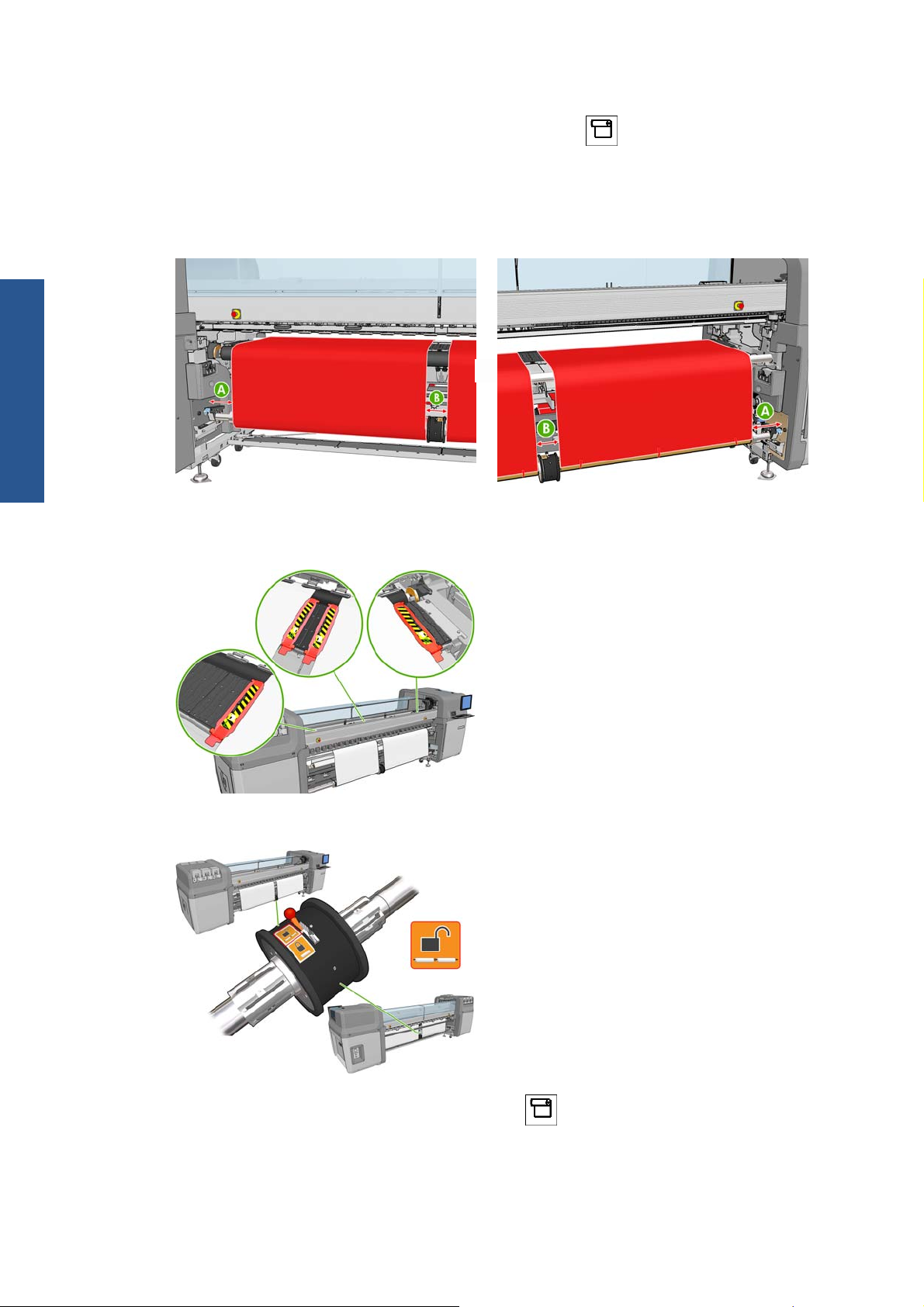
3. Lift the substrate pressure handles at the rear of the printer.
Load rolls into the printer
5
Page 10

4.
If you need to raise the carriage beam, go to the front panel and select the Substrate menu
then Substrate management, and press OK. Select Carriage beam position > Move to
highest position. This process takes about 2 minutes to complete.
,
Dual-roll spindle
The printer raises the carriage beam, making it easy to insert the substrate. This process takes
about 2 minutes to complete. During this period, you can load the input and output rolls.
NOTE: While the carriage beam is rising, you can stop it by pressing the Cancel key.
5. You may find it helpful to lock the differentials on the input and output spindles while loading.
6. Bring the new rolls on their spindle to the rear of the printer, with the geared end of the spindle on
the left.
7. If the two rolls are of unequal lengths, the longer roll should be on the right as seen from the front
of the printer; on the left as seen from the rear.
NOTE: When the shorter roll comes to an end, you should lock the differential hub if you intend
to continue printing on the longer roll.
8. Rest the ends of the spindle on the platforms provided at the rear of the printer; plastic pads are
provided to absorb the impacts.
6 Chapter 2 Use of the dual-roll spindle ENWW
Page 11

9. Open the latches at both ends of the spindle (if they were closed) and push the roll on its spindle
into the printer.
10. Close the latches to secure the spindle in place.
TIP: If you cannot close the gear side latch, try sliding the spindle towards the side plate to make
sure the end flange is not sitting on the bearings.
Dual-roll spindle
11. In the same way, load the spindle with the empty cores into the front of the printer. In this case, the
geared end of the spindle should be on the right.
12. Check that the printer has finished raising the carriage beam.
13. Pass the leading edges of both rolls through the printer to the output spindle.
TIP: LX850/LX820 only: Use the Media Loading Tool to load both rolls through the media
path at the same time.
ENWW
Load rolls into the printer
7
Page 12
14. Once in front of the printer, if you find that you haven't unrolled enough substrate, select Start
Dual-roll spindle
main roller motion from the front panel's Substrate menu
substrate unrolls only when you pull it.
15. Before taping the leading edges of the two substrate rolls to the empty cores on the output spindle,
check by measurement that they are in the same positions on the output spindle as on the input
spindle.
16. Tape the leading edges of both rolls to the empty cores on the output spindle.
17. Ensure that the four edge holders are correctly positioned, leaving the substrate free to move.
to unroll some more. The
18. Unlock the differentials on the input and output spindles.
19.
Go to the front panel and select the Substrate menu
press OK. Select Carriage beam position > Move to printing (normal) to lower the
carriage beam into its normal position, close to the substrate. This process takes about 2 minutes
to complete.
8 Chapter 2 Use of the dual-roll spindle ENWW
, then Substrate management, and
Page 13
NOTE: The Move to printing (custom) position allows you to set the printhead-to-substrate
distance for thick substrates or substrates that may wrinkle in the print zone, to avoid ink smearing.
Be aware that raising the printhead from the substrate may give poorer print quality.
WARNING! Do not insert your hands or anything else into the printer while the carriage beam
is descending.
20. Tell the printer to check the loaded substrate. The printer rotates the rolls to check their diameters,
and it also checks the width of the roll, the winding direction, the vacuum and the substrate
advance calibration (this takes 3–4 min).
NOTE: Some substrates (such as transparent substrates) cannot be measured by the printer in
this way. In such cases, you will be asked to enter the required information manually. Use the
scale on the curing module to see the value for the right-hand edge that must be entered manually.
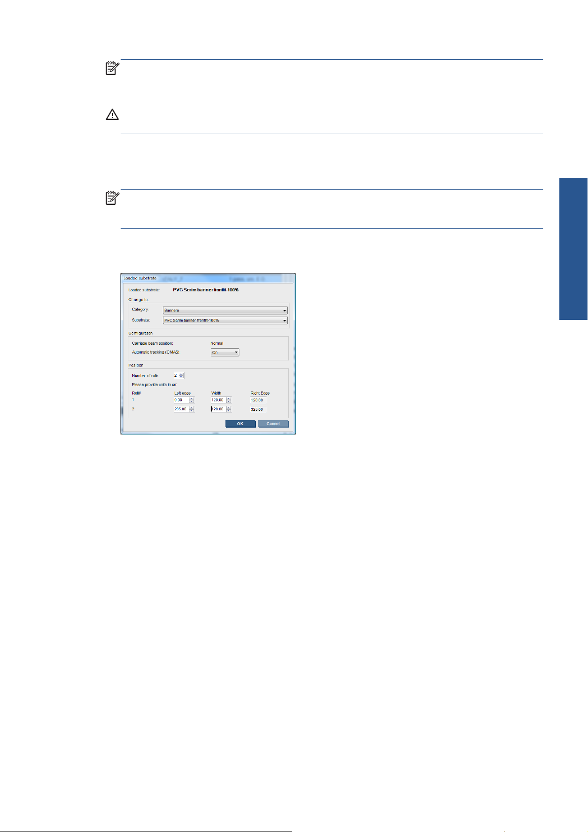
21. In the HP Internal Print Server, choose from the list of substrate types the type that you have
loaded.
Dual-roll spindle
The contents of the Loaded Substrate window are determined automatically when the substrate is
loaded and checked. However, if the printer is unable to detect the edges of the substrate (for
instance, in the case of a transparent substrate), you will have to measure the distance of the left
edge from the printer's side plate, and complete the Left Edge and Width fields yourself.
An alert regarding substrate advance tracking may appear at this point. For more information, see
your printer's documentation.
The printer is now ready to print.
ENWW
Load rolls into the printer
9
Page 14
Troubleshooting
3 Troubleshooting
If you see an error message numbered 78.2:01, it means that the substrate may have become
detached from the rear spindle, or the core is slipping on the dual roll. This could mean that you have
reached the end of the roll, or the roll is a non-standard size and is too big in diameter, or the dual-roll
differential hub is locked. The substrate is automatically unloaded when this error occurs.
You should respond to this error in the following ways.
Check whether you have reached the end of a roll.
●
For dual-roll printing, check that the differential hub is unlocked.
●
Check that the hubs are tightly secured to the spindle.
●
Check that the diameter of each substrate core is not too large for the spindle, if it is, move the
●
rubber ring of the Dual Roll to a larger diameter so that it grips the core tighter.
To check to see if the core is slipping on the dual roll, make a mark on the core and the on the
differential of the dual roll at the same level, and check if the marks separate as the substrate
advances. This type of issue will not trigger an error message, but there will be poor advance
accuracy, which will look like banding.
Check that each substrate core is tightly connected to the hubs on each side of it.
●
If the roll cannot be inserted on to the differential, ensure that the rubber ring is in the smallest
●
diameter slot.
If the substrate is skewed, check that the hubs are tightly connected to the spindle and to the substrate
core.
If you experience banding or lack of tension in the substrate, check that the differential hub is unlocked
and tightly connected to the spindle. Lack of tension can also occur when successive layers of substrate
stick to each other on the roll.
If you experience ink smears on the substrate after a period of dual-roll printing, try removing the
central edge holders.
10 Chapter 3 Troubleshooting ENWW
Page 15

4 Specifications
Printer length 126-in Printer 104-in Printer
Minimum roll width 914 mm (36 in) 914 mm (36 in)
Maximum roll width 2 × 1.52 m (2 × 60 in) 2 × 1.24 m (2 × 49 in)
Minimum gap between
rolls
Maximum roll diameter 250 mm (9.84 in) 250 mm (9.84 in)
Maximum total weight
of both rolls
152 mm (6 in) 152 mm (6 in)
2 × 60 kg (2 × 132 lb) 2 × 50 kg (2 × 110 lb)
ENWW 11
Specifications
 Loading...