

Page 1

Maintenance and Service
Guide
HP Special Edition L2000 Notebook PC
Compaq Presario V2000 Notebook PC
Document Part Number: 393671-001
The information and procedures included in this
✎
and Service Guide
Notebook PC models and Compaq Presario V2000 Notebook
PC models equipped with AMD processors.
July 2005
This guide is a troubleshooting reference used for maintaining
and servicing the notebook. It provides comprehensive
information on identifying notebook features, components, and
spare parts; troubleshooting notebook problems; and performing
notebook disassembly procedures.
apply to all HP Special Edition L2000
Maintenance
Page 2

© Copyright 2005 Hewlett-Packard Development Company, L.P.
Microsoft and Windows are U.S. registered trademarks of Microsoft
Corporation. AMD, Sempron, Turion, and combinations thereof, are
trademarks of Advanced Micro Devices, Inc. Bluetooth is a trademark
owned by its proprietor and used by Hewlett-Packard Company under
license. SD Logo is a trademark of its proprietor.
The information contained herein is subject to change without notice. The
only warranties for HP products and services are set forth in the express
warranty statements accompanying such products and services. Nothing
herein should be construed as constituting an additional warranty. HP shall
not be liable for technical or editorial errors or omissions contained herein.
Maintenance and Service Guide
HP Special Edition L2000 Notebook PC
Compaq Presario V2000 Notebook PC
First Edition: July 2005
Document Part Number: 393671-001
Page 3

Contents
1 Product Description
1.1 Features . . . . . . . . . . . . . . . . . . . . . . . . . . . . . . . . . . . 1–2
1.2 Resetting the Notebook . . . . . . . . . . . . . . . . . . . . . . . 1–4
1.3 Power Management. . . . . . . . . . . . . . . . . . . . . . . . . . 1–5
1.4 External Components . . . . . . . . . . . . . . . . . . . . . . . . 1–6
1.5 Design Overview. . . . . . . . . . . . . . . . . . . . . . . . . . . 1–20
2 Troubleshooting
2.1 Computer Setup. . . . . . . . . . . . . . . . . . . . . . . . . . . . . 2–1
2.2 Troubleshooting Flowcharts . . . . . . . . . . . . . . . . . . . 2–7
3 Illustrated Parts Catalog
3.1 Serial Number Location . . . . . . . . . . . . . . . . . . . . . . 3–1
3.2 Notebook Major Components. . . . . . . . . . . . . . . . . . 3–2
3.3 Mass Storage Devices . . . . . . . . . . . . . . . . . . . . . . . 3–10
3.4 Miscellaneous Plastics Kit . . . . . . . . . . . . . . . . . . . 3–12
3.5 Miscellaneous . . . . . . . . . . . . . . . . . . . . . . . . . . . . . 3–13
3.6 Sequential Part Number Listing . . . . . . . . . . . . . . . 3–14
4 Removal and Replacement Preliminaries
4.1 Tools Required . . . . . . . . . . . . . . . . . . . . . . . . . . . . . 4–1
4.2 Service Considerations . . . . . . . . . . . . . . . . . . . . . . . 4–1
4.3 Preventing Damage to Removable Drives . . . . . . . . 4–2
4.4 Preventing Electrostatic Damage . . . . . . . . . . . . . . . 4–3
4.5 Packaging and Transporting Precautions . . . . . . . . . 4–4
Maintenance and Service Guide iii
Page 4

Contents
4.6 Workstation Precautions . . . . . . . . . . . . . . . . . . . . . . 4–5
4.7 Grounding Equipment and Methods . . . . . . . . . . . . . 4–6
5 Removal and Replacement Procedures
5.1 Serial Number . . . . . . . . . . . . . . . . . . . . . . . . . . . . . . 5–2
5.2 Disassembly Sequence Chart . . . . . . . . . . . . . . . . . . 5–3
5.3 Preparing the Notebook for Disassembly . . . . . . . . . 5–4
5.4 Hard Drive. . . . . . . . . . . . . . . . . . . . . . . . . . . . . . . . . 5–6
5.5 Notebook Feet . . . . . . . . . . . . . . . . . . . . . . . . . . . . . 5–10
5.6 Memory Module . . . . . . . . . . . . . . . . . . . . . . . . . . . 5–11
5.7 Mini PCI Communications Module . . . . . . . . . . . . 5–14
5.8 Optical Drive. . . . . . . . . . . . . . . . . . . . . . . . . . . . . . 5–17
5.9 Switch Cover. . . . . . . . . . . . . . . . . . . . . . . . . . . . . . 5–19
5.10 Keyboard . . . . . . . . . . . . . . . . . . . . . . . . . . . . . . . . 5–21
5.11 Display Assembly . . . . . . . . . . . . . . . . . . . . . . . . . 5–24
5.12 Base Enclosure . . . . . . . . . . . . . . . . . . . . . . . . . . . 5–28
5.13 USB/S-Video Controller Board . . . . . . . . . . . . . . 5–31
5.14 Bluetooth Module . . . . . . . . . . . . . . . . . . . . . . . . . 5–33
5.15 Speaker Assembly. . . . . . . . . . . . . . . . . . . . . . . . . 5–35
5.16 RTC Battery . . . . . . . . . . . . . . . . . . . . . . . . . . . . . 5–36
5.17 Fan Assembly . . . . . . . . . . . . . . . . . . . . . . . . . . . . 5–38
5.18 Processor . . . . . . . . . . . . . . . . . . . . . . . . . . . . . . . . 5–40
5.19 System Board . . . . . . . . . . . . . . . . . . . . . . . . . . . . 5–42
5.20 LED Board . . . . . . . . . . . . . . . . . . . . . . . . . . . . . . 5–47
6 Specifications
A Connector Pin Assignments
B Power Cord Set Requirements
C Screw Listing
Index
iv Maintenance and Service Guide
Page 5
1
Product Description
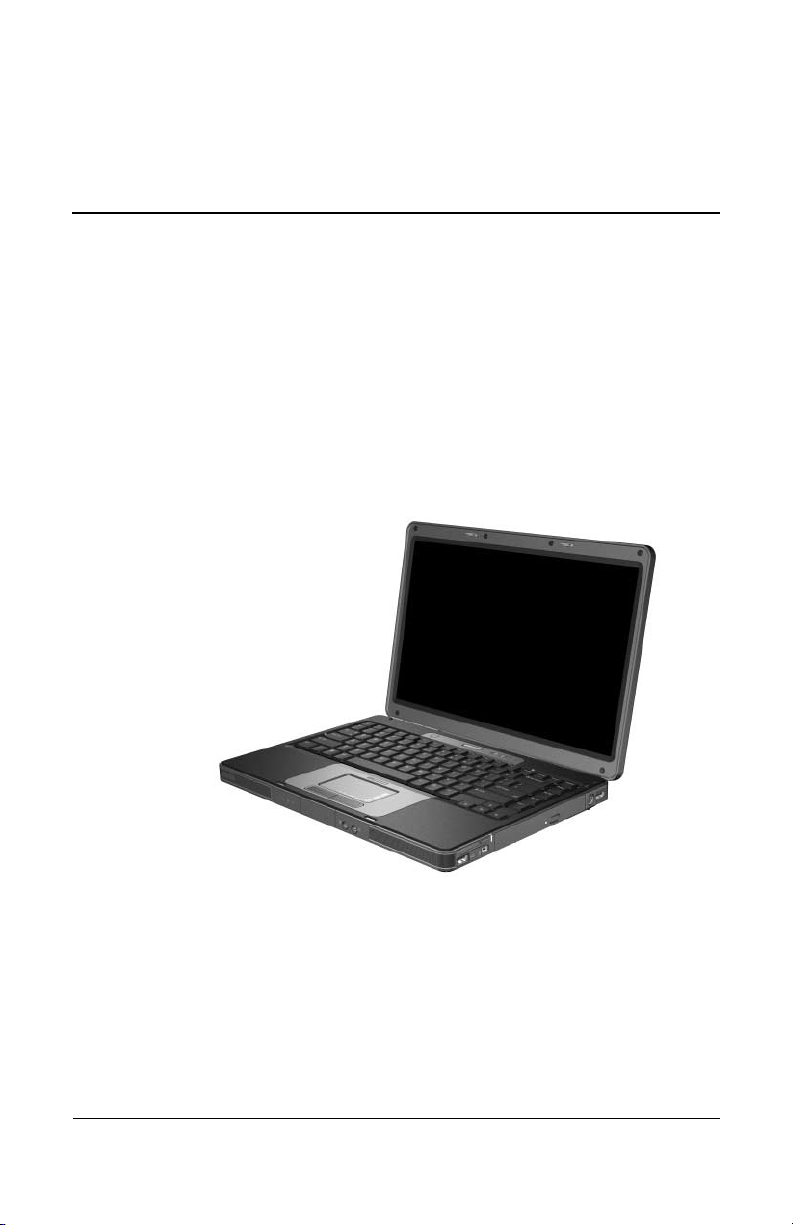
The HP Special Edition L2000 Notebook PC and the
Compaq Presario V2000 Notebook PC offer advanced
modularity, AMD Turion™ 64 Mobile Technology and
Mobile AMD Sempron™ processors, and extensive multimedia
support.
HP Special Edition L2000 and Compaq Presario V2000
Maintenance and Service Guide 1–1
Page 6

Product Description
1.1 Features
Numerous references are made throughout this Maintenance
✎
and Service Guide to “full-featured” and “defeatured” units. A
notebook model is considered to be full-featured if it has
3 Universal Serial Bus ports and the following components:
■ 6-in-1 digital card reader
■ Expansion port 2
■ Bluetooth wireless communications support
■ IEEE 1394 digital port
A notebook model is considered to be defeatured if it has only
2 Universal Serial Bus ports and none of the components in the
preceding list.
■ The following processors are available, varying by
notebook model:
❏ AMD Turion 64 ML-37 (2.0-GHz), ML-34 and ML-32
(1.8-GHz), and ML-30 and ML-28 (1.6-GHz) processors
❏ Mobile AMD Sempron 3300+ (2.0-GHz), 3000+
(1.8-GHz), and 2800+ (1.6-GHz) processors
■ 14.0-inch WXGA (1280 × 768) TFT display with over
16.7 million colors, varying by notebook model
■ 100-, 80-, 60-, or 40-GB high-capacity hard drive, varying by
notebook model
■ 256-MB DDR synchronous DRAM (SDRAM) at 333 MHz,
expandable to 2.0 GB on select models
■ Microsoft® Windows® XP Home Edition or Windows XP
Professional, varying by notebook model
■ Full-size Windows keyboard with embedded numeric keypad
■ TouchPad pointing device with on/off button and dedicated
two-way scroll region
1–2 Maintenance and Service Guide
Page 7

Product Description
■ Integrated 10/100 BASE-T Ethernet local area network
(LAN) network interface card (NIC) with RJ-45 jack
■ Integrated high-speed 56K modem with RJ-11 jack
■ Integrated wireless support for Mini PCI IEEE 802.11b/g
wireless local area network (WLAN) device
■ Support for one Type II PC Card slot, with support for both
32-bit (CardBus) and 16-bit PC Cards
■ External 65-watt AC adapter with 3-wire power cord
■ 6-cell or 12-cell Li-Ion battery pack
■ Stereo speakers with volume up and down buttons
■ Support for the following optical drives:
❏ 8X Max DVD-ROM drive
❏ 24X DVD/CD-RW Combo Drive
❏ 8X DVD±RW/R and CD-RW Combo Drive
❏ 8X DVD±RW/R and CD-RW Dual Layer Combo Drive,
LightScribe
■ Connectors:
❏ Audio-in (microphone)
❏ Audio-out (headphone)
❏ Memory card reader (select models only)
❏ Universal Serial Bus (USB) v. 2.0
❏ IEEE 1394 digital (select models only)
❏ S-Video-out (select models only)
❏ Power
❏ External monitor
❏ Docking (select models only)
❏ RJ-45 (network)
❏ RJ-11 (modem)
❏ PC Card
Maintenance and Service Guide 1–3
Page 8

Product Description
1.2 Resetting the Notebook
If the notebook you are servicing has an unknown password,
follow these steps to clear the password. These steps also
clear CMOS:
1. Prepare the notebook for disassembly (refer to Section 5.3,
“Preparing the Notebook for Disassembly,” for more
information).
2. Remove the real-time clock (RTC) battery (refer to
Section 5.16, “RTC Battery,” for more information).
3. Wait approximately 5 minutes.
4. Replace the RTC battery and reassemble the notebook.
5. Connect AC power to the notebook. Do not reinsert any
battery packs at this time.
6. Turn on the notebook.
All passwords and all CMOS settings have been cleared.
1–4 Maintenance and Service Guide
Page 9

1.3 Power Management
The notebook comes with power management features that
extend battery operating time and conserve power. The
notebook supports the following power management features:
■ Standby
■ Hibernation
■ Setting customization by the user
■ Hotkeys for setting the level of performance
■ Battery calibration
■ Lid switch standby/resume
■ Power/standby button
■ Advanced Configuration and Power Management (ACPM)
compliance
Product Description
Maintenance and Service Guide 1–5
Page 10
Product Description
1.4 External Components
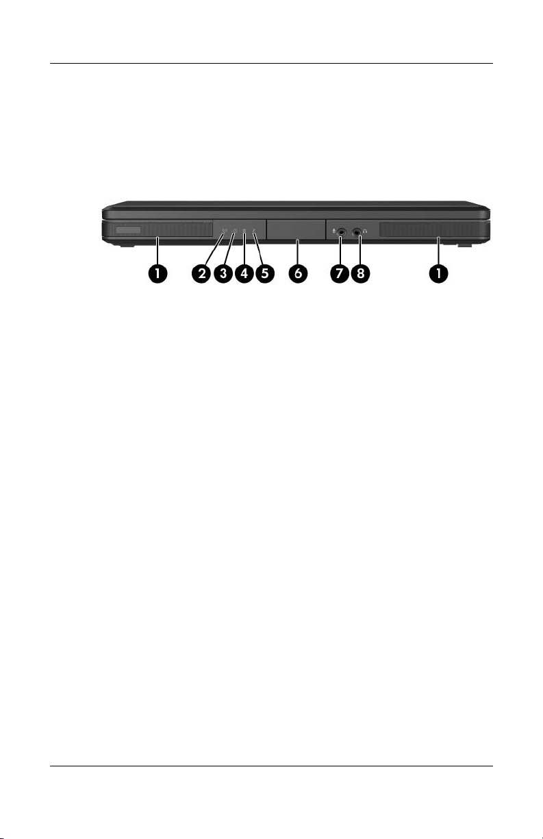
The external components on the front of the notebook are shown
below and described in Table 1-1.
Front Components
1–6 Maintenance and Service Guide
Page 11

Tabl e 1-1
Front Components
Item Component Function
1 Speakers (2) Produce stereo sound.
Product Description
2 Wireless light (select
models only)
3 Power/standby light
On: An integrated wireless device is
hardware enabled.
■ On: Notebook is turned on.
■ Blinking: Notebook is in standby.
■ Off: Notebook is off or in hibernation.
4 IDE (Integrated Drive
Electronics) drive light
5Battery light
■ On or blinking: The internal hard drive
or an optical drive is being accessed.
■ Amber: The battery pack is charging.
■ Green: The battery pack is fully
charged.
■ Off: The battery pack is discharging
or not inserted.
6 Display release latch Opens the notebook.
7Audio-in
(microphone) jack
8Audio-out
(headphone) jack
Connects an optional monaural (single
sound channel) microphone.
Connect optional headphones or powered
stereo speakers. Also connect the audio
function of an audio/video device such as
a television or VCR.
Maintenance and Service Guide 1–7
Page 12

Product Description
The external components on the right side of the notebook are
shown below and described in Table 1-2.
Right-Side Components
1–8 Maintenance and Service Guide
Page 13

Product Description
Tabl e 1-2
Right-Side Components
Item Component Function
1 USB connectors (2) Connect an optional USB device.
2 6-in-1 Memory Reader
(select models only)
3 1394 port
(select models only)
4 6-in-1 Memory Reader
light (select models
only)
5 Optical drive Supports an optical disc.
6S-Video-out jack
(select models only)
In Windows, supports digital memory cards.
Connects an optional 1394 device such
as a scanner, digital camera, or digital
camcorder.
On: A digital memory card is being
accessed.
Connects an optional S-Video device, such
as a television, VCR, camcorder, projector,
or video capture card.
Maintenance and Service Guide 1–9
Page 14
Product Description
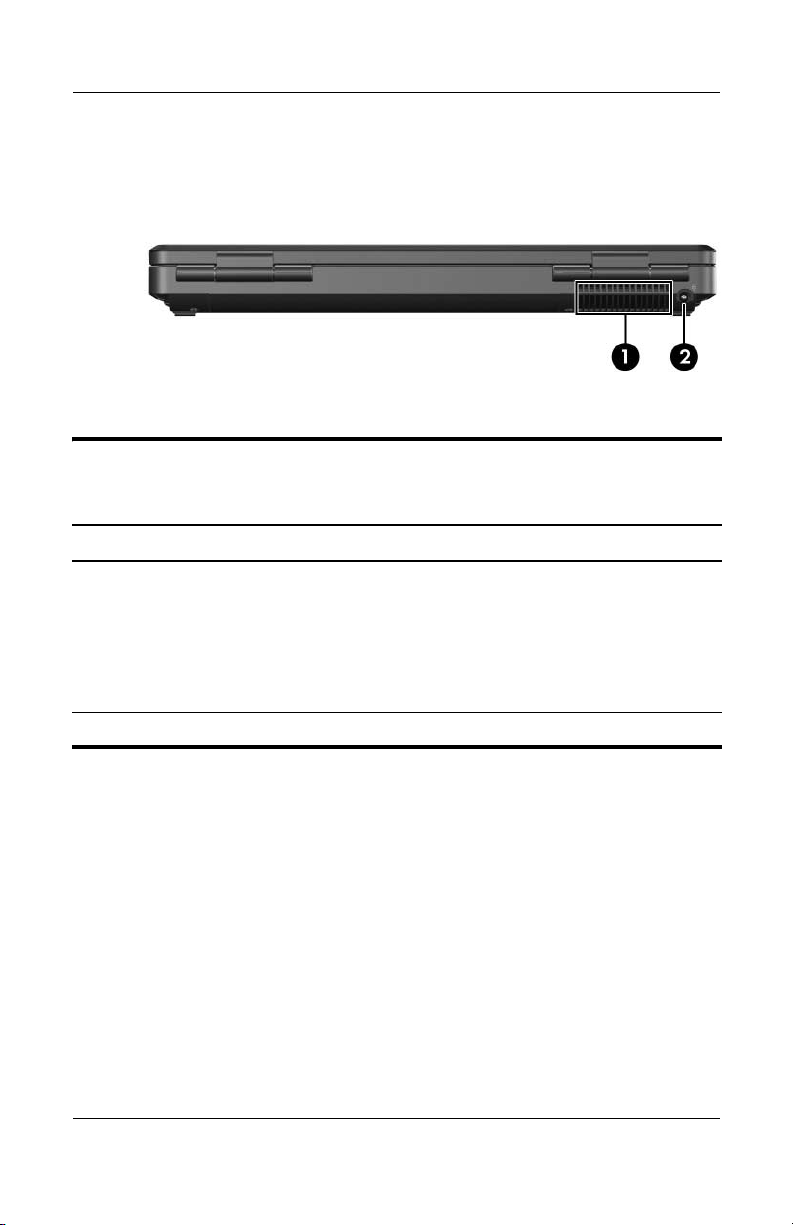
The external components on the notebook rear panel are shown
below and described in Table 1-3.
Rear Panel Components
Tabl e 1-3
Rear Panel Components
Item Component Function
1 Exhaust vent Provide airflow to cool internal components.
To prevent overheating, do not
Ä
obstruct vents. Do not allow a hard
surface, such as a printer, or a soft
surface, such as pillows, thick rugs
or clothing, to block airflow.
2 Power connector Connects an AC adapter cable.
1–10 Maintenance and Service Guide
Page 15
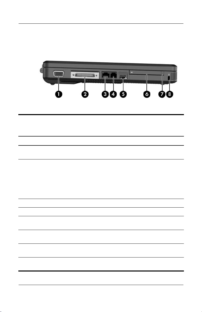
The external components on the left side of the notebook are
shown below and described in Table 1-4.
Left-Side Components
Tabl e 1-4
Left-Side Components
Item Component Function
Product Description
1 External monitor port Connects an optional VGA external monitor
2 Expansion port 2
(select models only)
3 RJ-45 (network) jack Connects an optional network cable.
4 RJ-11 (modem) jack Connects the modem cable.
5 USB connector (select
models only)
6 PC Card slot Supports an optional Type I or Type II 32-bit
7 PC Card eject button Ejects an optional PC Card from the
8 Security cable slot Attaches an optional security cable to the
Maintenance and Service Guide 1–11
or projector.
Connects the notebook to an optional
expansion base.
The notebook has only one
✎
expansion port. The term expansion
port 2 describes the type of
expansion port.
Connects an optional USB device.
(CardBus) or 16-bit PC Card.
PC Card slot.
notebook.
Page 16
Product Description
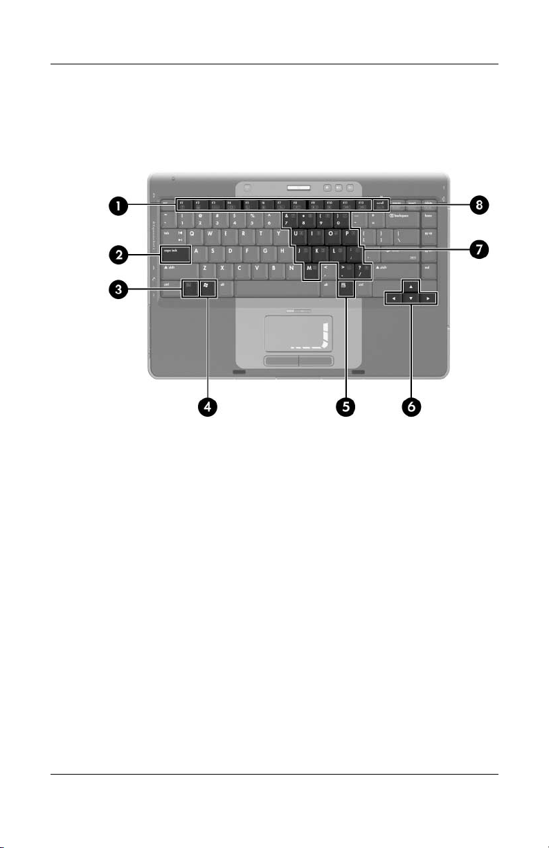
The notebook keyboard components are shown below and
described in Table 1-5.
Keyboard Components
1–12 Maintenance and Service Guide
Page 17

Product Description
Table 1-5
Keyboard Components
Item Component Function
1 F1 to F12 keys (12) Perform system and application tasks.
When combined with the fn key, several
keys and buttons perform additional tasks
as hotkeys.
2 caps lock key Enables caps lock and turns on the caps
3 Fn
4 Windows logo key In Windows, displays the Windows
5Windows
6 Arrow keys Move the cursor around the screen.
7 Keypad keys (15) In Windows, can be used like the keys
8 num lock key Enables numeric lock, turns on the
key Combines with other keys to perform
applications key
lock light.
system tasks. For example, pressing
fn+f7 decreases screen brightness.
Start menu.
In Windows, displays a shortcut menu
for items beneath the pointer.
on an external numeric keypad.
embedded numeric keypad, and turns
on the num lock light.
Maintenance and Service Guide 1–13
Page 18
Product Description
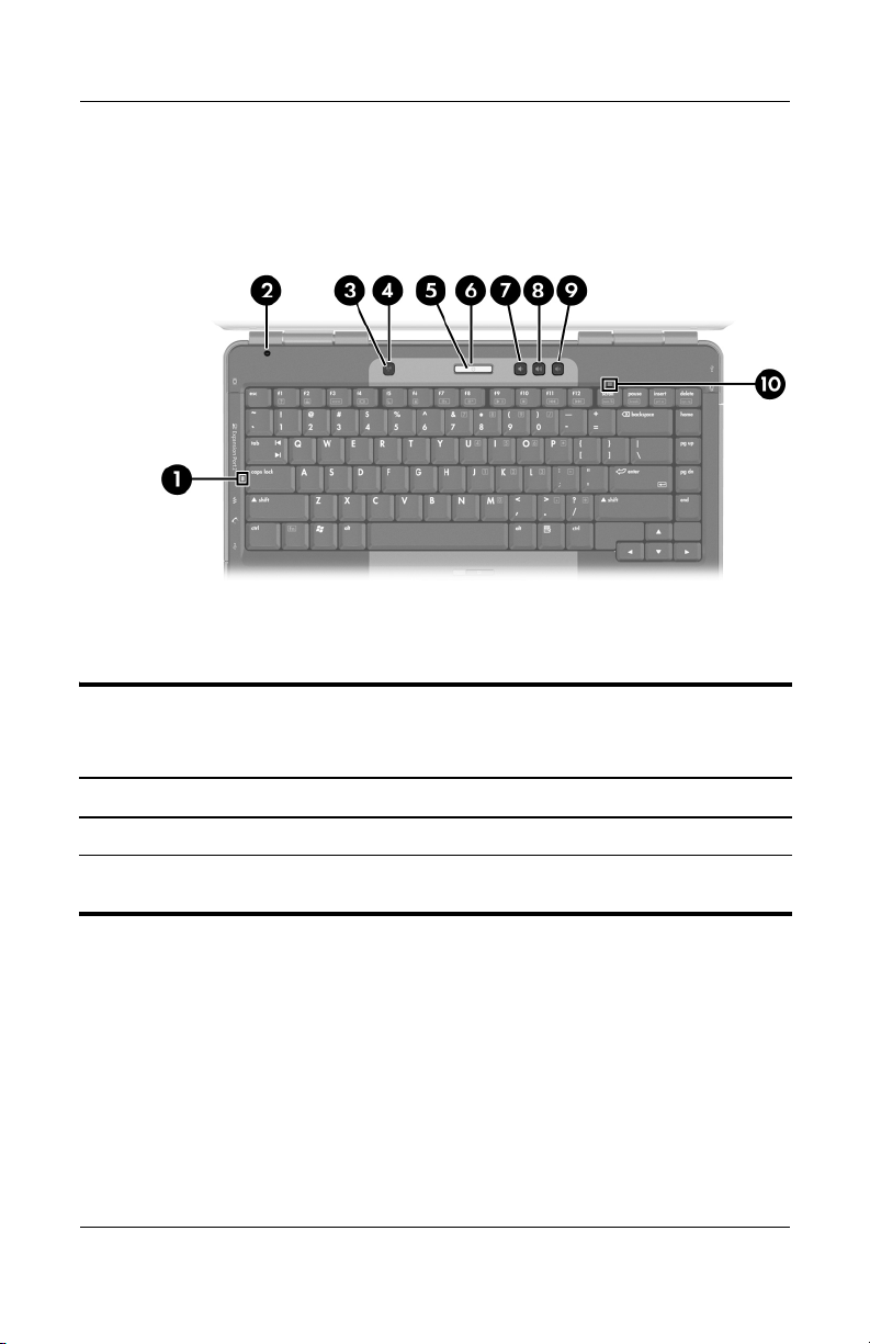
The notebook top components are shown below and described in
Table 1-6.
Top Components
Tabl e 1-6
Top Components
Item Component Function
1 Caps lock light On: Caps lock is on.
2 Display switch If the notebook is closed while on, turns off
the display.
1–14 Maintenance and Service Guide
Page 19

Tabl e 1-6
Product Description
Top Components
(Continued)
Item Component Function
3 Wireless button Enables/disables an internal wireless
device.
4 Wireless light On: an integrated wireless device is
hardware enabled.
5 Power button When the notebook is
■ Off, press to turn on the notebook.
■ On, briefly press to initiate hibernation.
■ In standby, briefly press to resume
from standby.
■ In hibernation, briefly press to restore
from hibernation.
6 Power/standby light
■ On: Notebook is turned on.
■ Blinking: Notebook is in standby.
■ Off: Notebook is off or in hibernation.
7 Volume down button Decreases system volume.
8 Volume up button Increases system volume.
9 Volume mute button Mutes or restores volume.
Mute light On: Volume is muted.
10 Num lock light On: Num lock or the internal keypad is on.
Maintenance and Service Guide 1–15
Page 20
Product Description
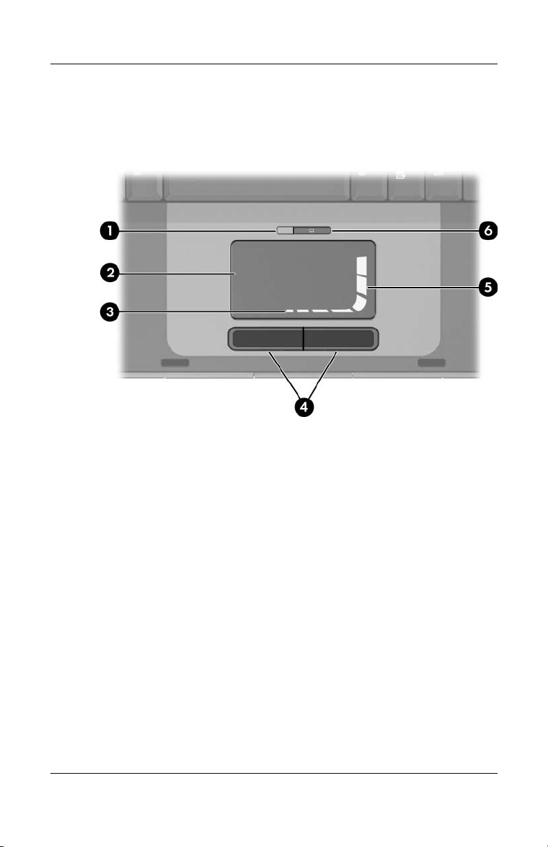
The notebook TouchPad components are shown below and
described in Table 1-7.
TouchPad Components
1–16 Maintenance and Service Guide
Page 21

Tabl e 1-7
TouchPad Components
Item Component Function
1 TouchPad light On: TouchPad is enabled.
2 TouchPad Moves the pointer.
Product Description
3 TouchPad horizontal
scrolling region
4 Left and right
TouchPad buttons
5 TouchPad vertical
scrolling region
6 TouchPad on/off
button
Scrolls toward left side or right side.
Function like the left and right buttons on an
external mouse.
Scrolls upward or downward.
Enables/disables the TouchPad.
Maintenance and Service Guide 1–17
Page 22
Product Description
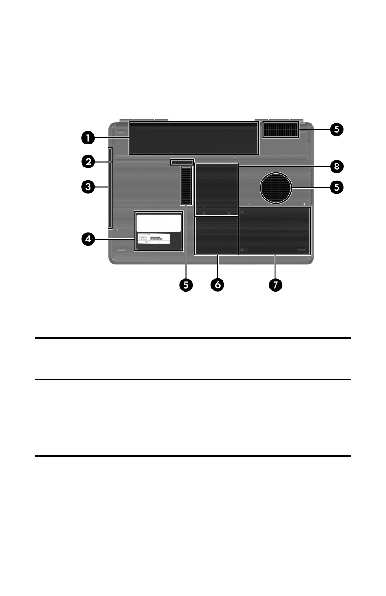
The external components on the bottom of the notebook are
shown below and described in Table 1-8.
Bottom Components
Table 1 -8
Bottom Components
Item Component Function
1 Battery pack Holds a battery pack.
2 Battery pack release latch Releases a battery pack from the
3 Optical drive Supports an optical disc.
1–18 Maintenance and Service Guide
battery bay.
Page 23

Table 1 -8
Product Description
Bottom Components
(Continued)
Item Component Function
4 Label areas (2) Contain the notebook serial number and
other applicable regulatory labels.
5 Exhaust vents (3) Provide airflow to cool internal
components.
To prevent overheating, do not
Ä
obstruct vents. Do not allow a
hard surface, such as a printer,
or a soft surface, such as pillows,
thick rugs or clothing, to block
airflow.
6 Mini PCI compartment Holds an optional wireless LAN device.
To prevent an unresponsive
Ä
system and the display of a
warning message, install only a
Mini PCI device authorized for
use in your notebook by the
governmental agency that
regulates wireless devices in your
country. If you install a device
and then receive a warning
message, remove the device to
restore notebook functionality.
Then contact Customer Care.
7 Hard drive bay Holds the internal hard drive.
8 Memory module
compartment
Maintenance and Service Guide 1–19
Contains 2 memory slots that support
replaceable memory modules. The
number of preinstalled memory
modules varies by notebook model.
Page 24

Product Description
1.5 Design Overview
This section presents a design overview of key parts and features
of the notebook. Refer to Chapter 3, “Illustrated Parts Catalog,”
to identify replacement parts, and Chapter 5, “Removal and
Replacement Procedures,” for disassembly steps.
The system board provides the following device connections:
■ AMD Turion 64 and Mobile AMD Sempron processors
■ Audio
■ Display assembly
■ Fan
■ Hard drive
■ Keyboard and TouchPad
■ Memory module
■ Mini PCI communications devices
■ PC Card
CAUTION: To properly ventilate the notebook, allow at least a 7.6-cm
Ä
(3-inch) clearance on the left and right sides of the notebook.
The notebook uses an electric fan for ventilation. The fan is
controlled by a temperature sensor and is designed to be turned
on automatically when high temperature conditions exist. These
conditions are affected by high external temperatures, system
power consumption, power management/battery conservation
configurations, battery fast charging, and software applications.
Exhaust air is displaced through the ventilation grill located on
the left side of the notebook.
1–20 Maintenance and Service Guide
Page 25

Troubleshooting
WARNING: Only authorized technicians trained by HP should repair
Å
this equipment. All troubleshooting and repair procedures are detailed
to allow only subassembly-/module-level repair. Because of the
complexity of the individual boards and subassemblies, do not attempt
to make repairs at the component level or modifications to any printed
wiring board. Improper repairs can create a safety hazard. Any
indication of component replacement or printed wiring board
modification may void any warranty or exchange allowances.
2.1 Computer Setup
Computer Setup is a preinstalled, ROM-based utility that can be
used even when the operating system is not working or will not
load. If the operating system is working, the notebook restarts the
operating system after you exit Computer Setup.
Pointing devices are not supported in Computer Setup; you
✎
must use the keyboard to navigate and make selections.
2
The menu tables later in this chapter provide an overview of
Computer Setup options.
Maintenance and Service Guide 2–1
Page 26

Troubleshooting
Accessing Computer Setup
The information and settings in Computer Setup are accessed
from the Main, Security, Advanced, Tools, and Exit menus.
1. Open Computer Setup by turning on or restarting the
notebook. Press
message is displayed in the lower-left corner of the screen.
❏ To change the language, use the arrow keys to select the
Advanced menu, select Language Support, and then
F5 or F6 until the appropriate language is
press
highlighted. Press
Advanced menu.
❏ To view navigation information, press F1.
❏ To return to the Computer Setup menu, press Esc.
2. Select the Main, Security, Advanced, Tools, and Exit
menus.
3. To exit Computer Setup, choose one of the following:
❏ To exit without saving any changes, use the arrow keys to
select Exit > Exit Discarding Changes, and then follow
the instructions on the screen.
F10 while the “Press <F10> to enter Setup”
F10 to save your selection and exit the
❏ To exit and save all the settings you have entered, use the
arrow keys to select Exit > Exit Saving Changes, and
then follow the instructions on the screen.
Your preferences are set when you exit Computer Setup and take
effect when the notebook restarts.
2–2 Maintenance and Service Guide
Page 27

Computer Setup Defaults
To return all settings in Computer Setup to the values that were
set at the factory:
1. Open Computer Setup by turning on or restarting the
notebook. Press
message is displayed in the lower-left corner of the screen.
❏ To change the language, use the arrow keys to select the
Advanced menu, select Language Support, and then
F5 or F6 until the appropriate language is
press
highlighted. Press
Advanced menu.
❏ To view navigation information, press F1.
2. Use the arrow keys to select Exit > Load Setup Defaults.
F10 while the “Press <F10> to enter Setup”
F10 to save your selection and exit the
Troubleshooting
3. Press
F9.
4. Press enter to confirm the return to default configuration.
5. To confirm the restoration, press
F10.
6. Select Exit > Exit Saving Changes, and then follow the
instructions on the screen.
When the computer restarts, the factory settings are restored, and
any identification information you have entered is saved.
Maintenance and Service Guide 2–3
Page 28

Troubleshooting
Selecting from the Main Menu
Table 2 -1
Main Menu
Select To Do This
System Information ■ View identification information about the
notebook.
■ View specification information about the
processor, memory and cache size, keyboard
controller version, and system BIOS.
Selecting from the Security Menu
Table 2 -2
Security Menu
Select To Do This
Administrator password Enter, change, or delete an HP Administrator
password.
Power-on password Enter, change, or delete a power-on password.
DriveLock password Enable/disable DriveLock; change a DriveLock
user or master password.
DriveLock Settings are accessible only
✎
when you enter Computer Setup by turning
on (not restarting) the notebook.
Device security Enable diskette drive or optical drive for inclusion
in MultiBoot.
2–4 Maintenance and Service Guide
Page 29

Troubleshooting
Selecting from the Advanced Menu
Table 2 -3
Advanced Menu
Select To Do This
Video Graphic Mode Select UMA, SidePort, or UMA+SidePort video
memory modes.
Dedicated Video Memory View the size of the on-board video memory.
Total Video Memory View the size of the total system video memory.
Language Support Change the Computer Setup language.
Boot Order Set the boot order.
Accessibility Options Provides access to electronic and information
technology to a wide range of people with
disabilities.
Embedded WLAN device Enable/disable a wireless local area network
device.
Embedded Bluetooth
device
Enable/disable a Bluetooth device.
Selecting from the Tools Menu
Table 2 -4
Tools M enu
Select To Do This
HDD Self-test Run a quick or comprehensive self-test on any
hard drive in the system.
Maintenance and Service Guide 2–5
Page 30

Troubleshooting
Table 2 -5
Exit Menu
Select To Do This
Exit Saving Changes Save changes entered during the current session.
Then exit and restart the notebook. The changes
you save are in effect when the notebook restarts.
Exit Discarding Changes Cancel changes entered during the current
session. Then exit and restart the notebook.
Load Setup Defaults Replace configuration settings in Computer Setup
with factory default settings. (Identification
information is retained.)
2–6 Maintenance and Service Guide
Page 31

Troubleshooting
2.2 Troubleshooting Flowcharts
Tabl e 2-6
Troubleshooting Flowcharts Overview
Flowchart Description
2.1 “Flowchart 2.1—Initial Troubleshooting”
2.2 “Flowchart 2.2—No Power, Part 1”
2.3 “Flowchart 2.3—No Power, Part 2”
2.4 “Flowchart 2.4—No Power, Part 3”
2.5 “Flowchart 2.5—No Power, Part 4”
2.6 “Flowchart 2.6—No Video, Part 1”
2.7 “Flowchart 2.7—No Video, Part 2”
2.8 “Flowchart 2.8—Nonfunctioning Docking Device (if applicable)”
2.9 “Flowchart 2.9—No Operating System (OS) Loading”
2.10 “Flowchart 2.10—No OS Loading, Hard Drive, Part 1”
2.11 “Flowchart 2.11—No OS Loading, Hard Drive, Part 2”
2.12 “Flowchart 2.12—No OS Loading, Hard Drive, Part 3”
2.13 “Flowchart 2.13—No OS Loading, Diskette Drive”
Maintenance and Service Guide 2–7
Page 32

Troubleshooting
Tabl e 2-6
Troubleshooting Flowcharts Overview
Flowchart Description
2.14 “Flowchart 2.14—No OS Loading, Optical Drive”
2.15 “Flowchart 2.15—No Audio, Part 1”
2.16 “Flowchart 2.16—No Audio, Part 2”
2.17 “Flowchart 2.17—Nonfunctioning Device”
2.18 “Flowchart 2.18—Nonfunctioning Keyboard”
2.19 “Flowchart 2.19—Nonfunctioning Pointing Device”
2.20 “Flowchart 2.20—No Network/Modem Connection”
(Continued)
2–8 Maintenance and Service Guide
Page 33

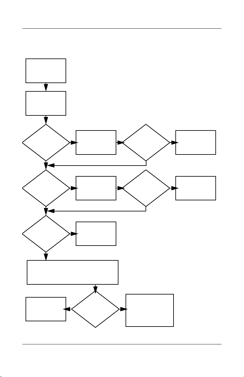
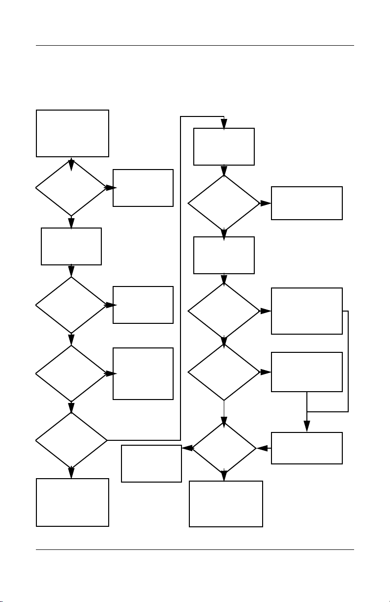
Flowchart 2.1—Initial Troubleshooting
Begin
troubleshooting.
N
Go to
Is there
power?
Y
N
Beeps,
LEDs, or error
messages?
Y
N
Is there video?
(no boot)
Y
N
Is the OS
loading?
Y
N
Is there
sound?
Y
“Flowchart
2.2—No Power,
Par t 1.”
Check
LED board,
speaker
connections.
Go to
“Flowchart
2.6—No Video,
Part 1.”
Go to
“Flowchart
2.9—No Operating
System (OS)
Loading.”
Go to
“Flowchart
2.15—No Audio,
Par t 1.”
N
All drives
working?
Y
N
Keyboard/
pointing
device
working?
Y
N
Connecting
to network
or modem?
Y
End
Troubleshooting
Go to
“Flowchart
2.17—Nonfunctioning Device.”
Go to
“Flowchart
2.18—Nonfunc-
tioning Keyboard”
or “Flowchart
2.19—Nonfunctioning Pointing
Device.”
Go to
“Flowchart
2.20—No
Network/Modem
Connection.”
Maintenance and Service Guide 2–9
Page 34
Troubleshooting
N
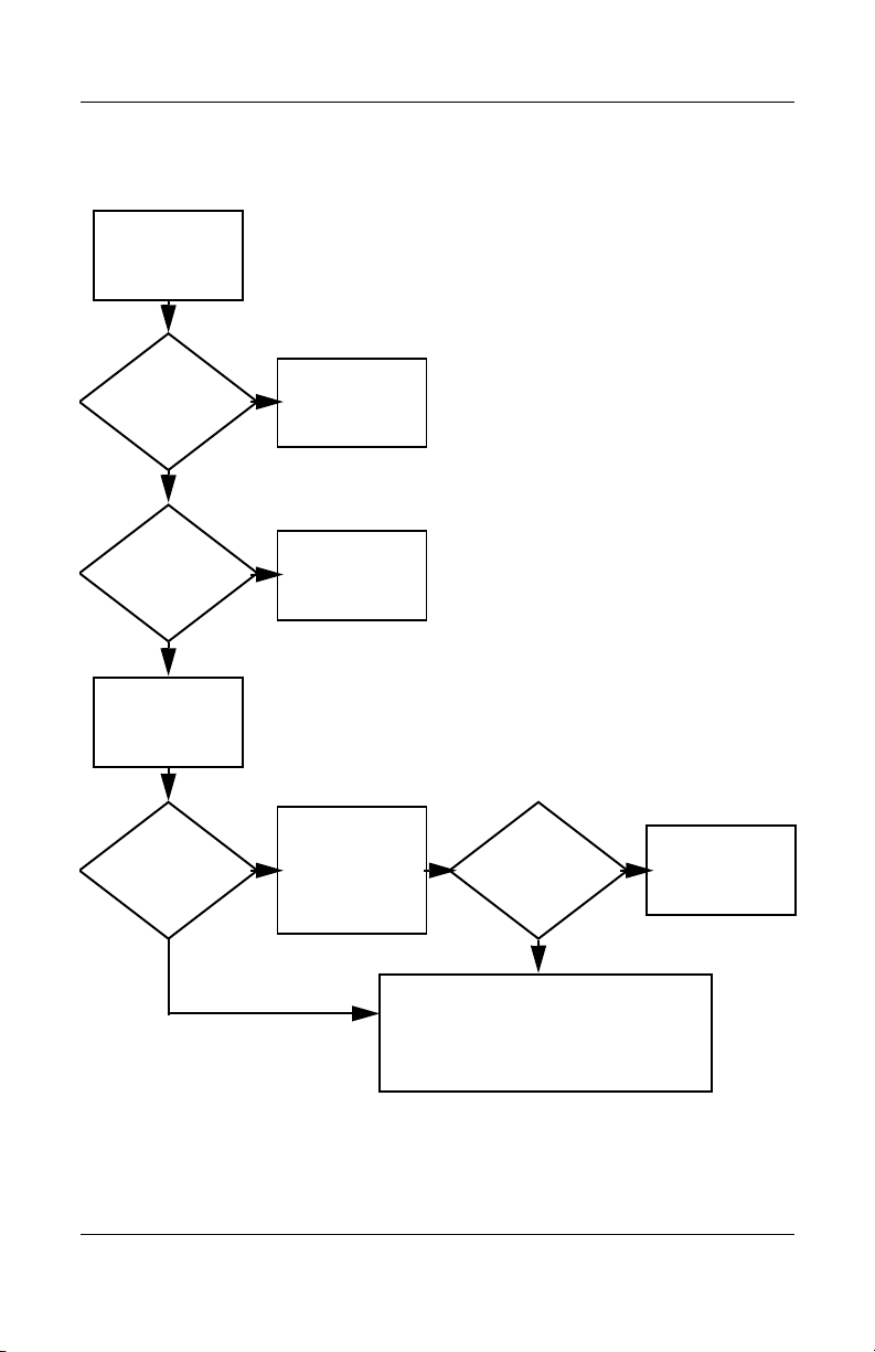
Flowchart 2.2—No Power, Part 1
No power
(power LED
is off).
Remove from
docking device
(if applicable).
N
Go to
“Flowchart
2.3—No Power,
Par t 2.”
N
Go to
“Flowchart
2.4—No Power,
Part 3.”
Y
Y
Power up
on battery
power?
Power up
on AC
power?
N
Reset
power.*
Power up
on battery
power?
Y
N
Reset
power.*
Power up
on AC power?
Y
Y
Power up in
docking
device?
1. Reseat the power cables in the docking
device and at the AC outlet.
2. Ensure the AC power source is active.
3. Ensure that the power strip is working.
Done
YN
Done
Power up
in docking
device?
*NOTES
1. On select models, there is a separate
reset button.
2. On select models, the notebook can be
reset using the standby switch and
either the lid switch or the main power
switch.
Go to
“Flowchart
2.8—Nonfunctioning
Docking Device (if
applicable).”
2–10 Maintenance and Service Guide
Page 35
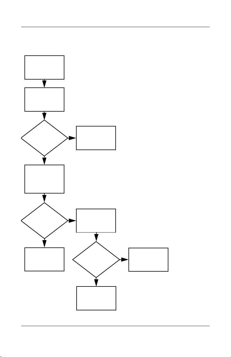
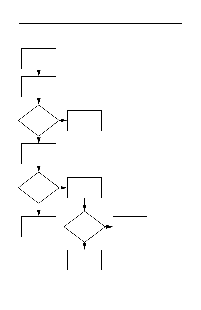
Flowchart 2.3—No Power, Part 2
N
Continued from
“Flowchart
2.2—No Power,
Par t 1.”
Visually check for
debris in battery
socket and clean
if necessary.
Y
Troubleshooting
Power on?
Check battery by
recharging it,
moving it to
another notebook,
or replacing it.
Done
N
Power on?
Replace
power supply
(if applicable).
Y
N
Go to
Done
Power on?
“Flowchart
2.4—No Power,
Part 3.”
Y
Done
Maintenance and Service Guide 2–11
Page 36

Troubleshooting
Flowchart 2.4—No Power, Part 3
Continued from
“Flowchart
2.3—No Power,
Part 2.”
Plug directly
into AC outlet.
Y
Power LED
on?
N
Reseat AC adapter
in notebook and
at power source.
Power on?
N
Power outlet
active?
Y
Replace
power cord.
Power on?
Done
Y
Done
External
N
Try different
outlet.
Internal or
external AC
adapter?
Internal
Go to
“Flowchart
2.5—No Power,
Part 4.”
Replace external
AC adapter.
N
Power on?
Y
Y
Done
Done
N
2–12 Maintenance and Service Guide
Page 37

Flowchart 2.5—No Power, Part 4
Continued from
“Flowchart
2.4—No Power,
Par t 3.”
Open
notebook.
Troubleshooting
N
Y
Loose or
damaged
parts?
Close
notebook and
retest.
Power on?
Done
Y
Reseat loose
components and
boards and
replace damaged
items.
N
Replace the following items (if applicable). Check
notebook operation after each replacement:
1. Internal DC-DC converter*
2. Internal AC adapter
3. Processor board*
4. System board*
*NOTE: Replace these items as a set to prevent
shorting out among components.
Maintenance and Service Guide 2–13
Page 38

Troubleshooting
Flowchart 2.6—No Video, Part 1
No video.
Docking Device
Stand-alone
or docking
device?
Go to
“Flowchart
2.7—No Video,
Part 2.”
*NOTE: To change from internal to
external display, use the hotkey
combination.
Stand-alone
Internal or
external
display*?
External
Adjust
brightness.
Internal
Y
Video OK? Done
N
Check for bent
pins on cable.
N
Video OK?
Adjust
brightness.
Video OK? Done
N
A
Press lid
switch to ensure
operation.
Video OK? Done
N
Replace the following one at a time. Test after each replacement.
1. Cable between notebook and notebook display (if applicable)
2. Display
3. System board
Try
another
display.
Internal and
external
video OK?
Y
Y
N
Replace
system
board.
YY
Done
Done
2–14 Maintenance and Service Guide
Page 39
Flowchart 2.7—No Video, Part 2
Continued from
“Flowchart
2.6—No Video,
Part 1.”
Remove
notebook from
docking device,
if connected.
Troubleshooting
Adjust
display
brightness.
N
Video OK?
Y
Check that notebook is properly
seated in docking device,
for bent pins on cable,
and for monitor connection.
Y
Video OK?
N
Adjust external
monitor display.
Go to “A” in
“Flowchart
2.6—No Video,
Part 1.”
Done
Check brightness
of external
monitor.
Video OK?
N
Try another
external
monitor.
Internal
and external
video OK?
N
Go to
“Flowchart
2.8—Nonfunctioning
Docking Device (if
applicable).”
Y
Done
Y
Done
Maintenance and Service Guide 2–15
Page 40

Troubleshooting
Flowchart 2.8—Nonfunctioning Docking Device
(if applicable)
Nonfunctioning
docking device.
Reseat power
cord in docking
device and
power outlet.
Check voltage
setting on docking
device.
Reset monitor
cable connector at
docking device.
Docking
device
operating?
N
Remove notebook,
replace docking
device.
Reinstall
notebook into
docking device.
Y
Docking
device
operating?
Y
Done
N
Test replacement
docking device with
new notebook.
Done
2–16 Maintenance and Service Guide
Page 41
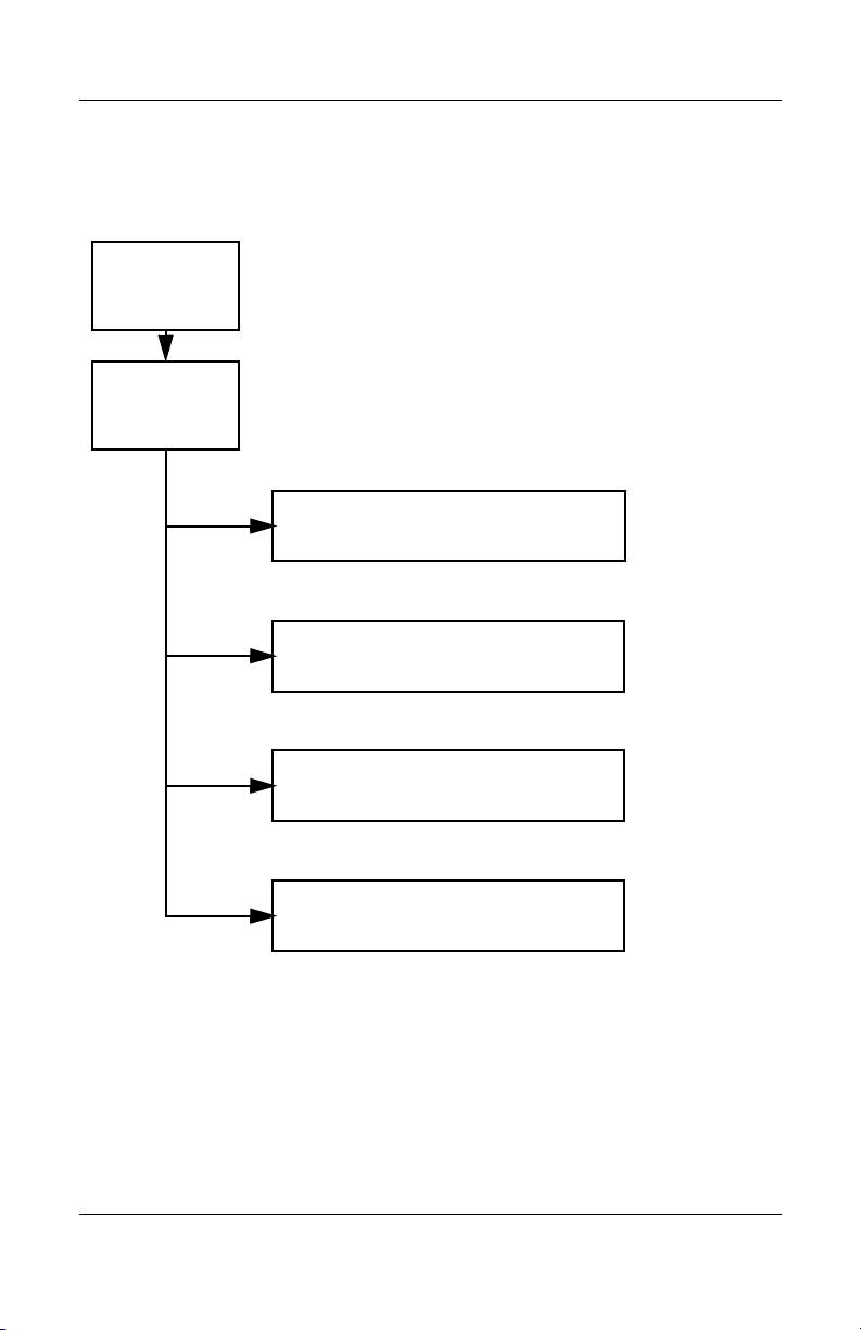
Troubleshooting
Flowchart 2.9—No Operating System (OS)
Loading
No OS
loading.*
Reseat power
cord in docking
device and
power outlet.
No OS loading from hard drive,
“Flowchart 2.10—No OS Loading,
go to
go to
Hard Drive, Part 1.”
No OS loading from diskette drive,
“Flowchart 2.13—No OS Loading,
Diskette Drive.”
No OS loading from optical drive,
“Flowchart 2.14—No OS Loading,
go to
“Flowchart 2.20—No Network/Modem
go to
*NOTE: Before beginning troubleshooting, always
check cable connections, cable ends, and drives
for bent or damaged pins.
Optical Drive.”
No OS loading from network,
Connection.”
Maintenance and Service Guide 2–17
Page 42

Troubleshooting
Flowchart 2.10—No OS Loading, Hard Drive,
Part 1
OS not
loading from
hard drive.
Nonsystem
disk message?
N
Reseat
external
hard drive.
OS loading?
N
Boot
from
CD?
Y
Check the Setup
utility for correct
booting order.
Boot
from
hard drive?
Y
Done
Y
Go to
“Flowchart
2.11—No OS
Loading,
Hard Drive, Part 2.”
Y
Done
N
N
Boot
from
diskette?
Y
N
Change boot
priority through
the Setup utility
and reboot.
Go to
“Flowchart
2.13—No OS
Loading,
Diskette Drive.”
N
Boot
from
hard drive?
2.17—Nonfunctioning
Go to
“Flowchart
Device.”
Y
2–18 Maintenance and Service Guide
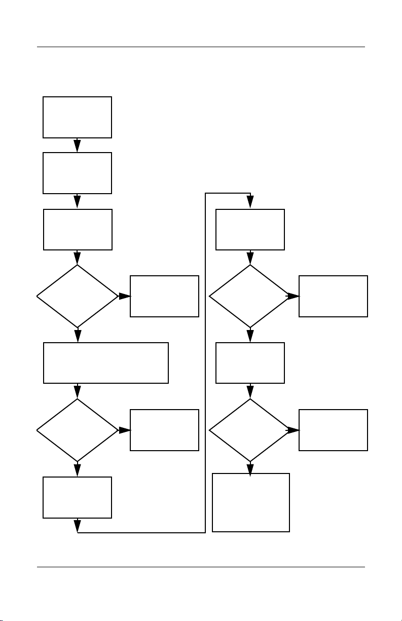
Page 43
Troubleshooting
Flowchart 2.11—No OS Loading, Hard Drive,
Part 2
Continued from
“Flowchart
2.10—No OS
Loading,
Hard Drive, Part 1.”
Disc or
diskette in
drive?
Y
Remove disc or
diskette and
reboot.
N
1. Replace
hard drive.
2. Replace
system board.
N
Reseat
hard drive.
Hard drive
accessible?
Run FDISK.
Y
Done
N
from diskette
Y
Boot
from
hard drive?
Boot
drive?
Y
N
Diskette Drive.”
Done
Go to
“Flowchart
2.13—No OS
Loading,
Hard drive
partitioned?
Y
Hard drive
formatted?
Y
N
Create partition,
and then format
hard drive to
bootable
C:\ prompt.
N
Format hard drive
and bring to
abootable
C:\ prompt.
N
Y
Notebook
booted?
Load OS using
Operating System disc
(if applicable).
Y
Hard drive
accessible?
Done
N
Go to
“Flowchart
2.12—No OS
Loading,
Hard Drive, Part 3.”
Maintenance and Service Guide 2–19
Go to
“Flowchart
2.12—No OS
Loading,
Hard Drive, Part 3.”
Page 44

Troubleshooting
Flowchart 2.12—No OS Loading, Hard Drive,
Part 3
Continued from
“Flowchart
2.11—No OS
Loading,
Hard Drive, Part 2.”
N
System
files on hard
drive?
Y
Install OS
and reboot.
Virus
on
hard drive?
N
Run SCANDISK and
check for
bad sectors.
Can bad
sectors
be fixed?
Y
Fix bad
sectors.
Y
OS
Clean virus.
loading from
hard drive?
Y
Done
N
Y
Diagnostics on
disc or diskette?
Run diagnostics
and follow
recommendations.
N
N
Replace
hard drive.
Replace
hard drive.
N
Boot from
hard drive?
Replace
hard drive.
Y
Done
2–20 Maintenance and Service Guide
Page 45

Troubleshooting
N
N
Flowchart 2.13—No OS Loading, Diskette Drive
Y
OS not loading
from
diskette drive.
Reseat
diskette drive.
OS
loading?
Done
N
Nonsystem
disk message?
Y
Bootable
diskette
in drive?
N
Install bootable
diskette and
reboot notebook.
Y
N
Boot
from another
device?
Y
Go to
“Flowchart
2.17—Nonfunctioning Device.”
N
Diskette
drive enabled
in the Setup
utility?
Enable drive
and cold boot
notebook.
Y
Y
Reset the notebook.
Is diskette
drive boot
order
correct?
Refer to
Section 1.2,
“Resetting the
Notebook,”
instructions.
for
Check diskette
for system files.
Try d iff er ent
diskette.
Nonsystem
disk error?
N
loading?
N
OS
Y
Replace the following
components
individually, retesting
after each
replacement:
■ Diskette drive
■ System board
Y
Done
Change boot
priority using
the Setup utility.
2.17—Nonfunctioning
Go to
“Flowchart
Device.”
Maintenance and Service Guide 2–21
Page 46

Troubleshooting
Flowchart 2.14—No OS Loading, Optical Drive
loading from
CD-ROM or
DVD-ROM drive.
Boots from
CD or DVD?
N
Reseat
No OS
drive.
N
bootable disc.
Disc
in drive?
Install
Y
Bootable
disc in
drive?
Y
Try another
bootable disc.
N
Install bootable
disc and
reboot
notebook.
Y
Done
Y
Boots from
CD or DVD?
Done
N
Y
Booting
from another
device?
N
2.17—Nonfunctioning
Go to
“Flowchart
Device.”
Reset the notebook.
Booting
correct?
N
Correct boot
order using
the Setup utility.
order
Y
Refer to
Section 1.2,
“Resetting the
Notebook,”
instructions.
for
2.17—Nonfunctioning
Go to
“Flowchart
Device.”
2–22 Maintenance and Service Guide
Page 47

Flowchart 2.15—No Audio, Part 1
N
Turn up audio
No audio.
internally or
externally.
Audio? Done
N
Troubleshooting
Y
Notebook in
docking device
(if applicable)?
Y
Undock
Internal
audio?
N
Go to
“Flowchart
2.16—No Audio,
Par t 2.”
Y
Go to
“Flowchart
2.16—No Audio,
Par t 2.”
Dock notebook in
replacement
docking device.
Y
Go to
“Flowchart
2.17—Nonfunctioning
Device.”
Audio? Done
N
Maintenance and Service Guide 2–23
Page 48
Troubleshooting
Flowchart 2.16—No Audio, Part 2
Continued from
“Flowchart
2.15—No Audio,
Part 1.”
N
Audio
driver in OS
configured?
Y
N
Correct
drivers for
application?
Y
Connect to
external
speaker.
Reload
audio drivers.
Load drivers and
set configuration
in OS.
Replace audio
board and
Audio?
YN
speaker
connections
in notebook
(if applicable).
Audio? Done
Replace the following components individually,
retesting after each replacement:
YN
■ Internal speakers.
■ Audio board (if applicable).
■ System board.
2–24 Maintenance and Service Guide
Page 49

Flowchart 2.17—Nonfunctioning Device
Nonfunctioning
device.
Reseat
device.
Unplug the nonfunctioning device from the notebook
and inspect cables and plugs for bent or broken pins
Clear
CMOS.
Reattach device.
Close notebook,
plug in power,
and reboot.
or other damage.
Any physical
device detected?
N
Replace hard drive.
Y
Operating System
Troubleshooting
Fix or
replace
broken item.
Go to
“Flowchart
2.9—No
(OS) Loading.”
N
Device
boots
properly?
Y
Done
Replace NIC.
If integrated NIC,
replace system
board.
Y
Replace diskette
drive.
Maintenance and Service Guide 2–25
Device
boots
properly?
Done
N
Page 50
Troubleshooting
Flowchart 2.18—Nonfunctioning Keyboard
Keyboard
not operating
properly.
Connect notebook
to good external
keyboard.
N
Y
Reseat internal
connector
(if applicable).
Y
External
device
works?
keyboard
Replace
system
board.
N
Keyboard
operating
properly?
Replace internal
keyboard or
cable.
Y
Keyboard
Done Done
operating
properly?
N
Replace
system
board.
2–26 Maintenance and Service Guide
Page 51

Troubleshooting
Flowchart 2.19—Nonfunctioning Pointing
Device
Pointing device
not operating
properly.
Connect notebook
to good external
pointing device.
N
External
device
works?
Y
Reseat internal
pointing device
connector
(if applicable).
Replace
system
board.
N
Pointing device
operating
properly?
Replace internal
pointing device
or cable.
Y
Y
Done Done
Pointing device
operating
properly?
N
Replace
system
board.
Maintenance and Service Guide 2–27
Page 52

Troubleshooting
Flowchart 2.20—No Network/Modem
Connection
No network
or modem
connection.
N
Network
or modem jack
active?
Y
Digital
line?
N
Replace jack
or have jack
activated.
Y
Connect
to nondigital
line.
Y
Done
Y
Disconnect all
the notebook
NIC/modem
configured
in OS?
power from
and open.
N
Reload
drivers and
reconfigure.
Network
or modem
connection
working?
N
Replace NIC/modem
(if applicable).
Y
Reseat NIC/modem
(if applicable).
Network
or modem
connection
working?
Done
N
Replace
system
board.
2–28 Maintenance and Service Guide
Page 53

Illustrated Parts Catalog
This chapter provides an illustrated parts breakdown and a
reference for spare part numbers and option part numbers.
3.1 Serial Number Location
When ordering parts or requesting information, provide the
notebook serial number and model number located on the bottom
of the notebook.
3
Serial Number Location
Maintenance and Service Guide 3–1
Page 54

Illustrated Parts Catalog
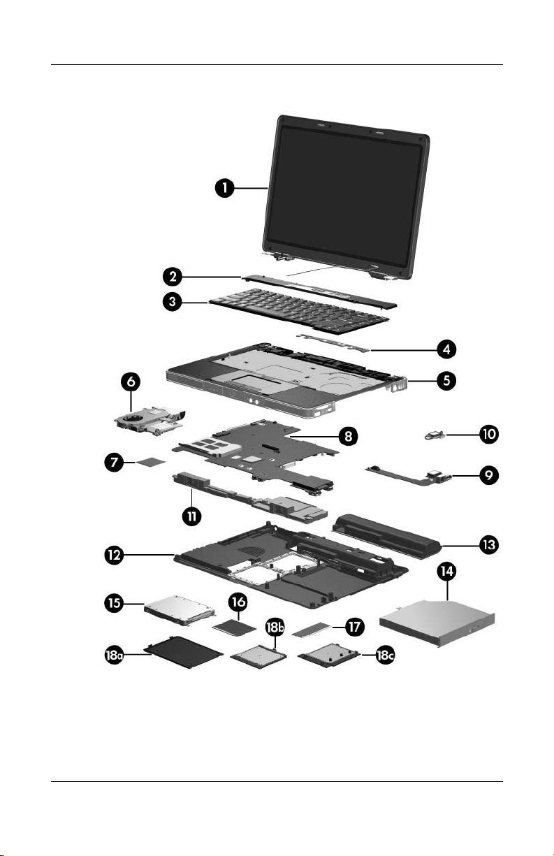
3.2 Notebook Major Components
Notebook Major Components
3–2 Maintenance and Service Guide
Page 55

Illustrated Parts Catalog
Tabl e 3-1
Spare Parts: Notebook Major Components
Spare Part
Item Description
1 Display assemblies (include wireless antenna boards and cables)
For use on HP Special Edition L2000 models
14.0-inch, WXGA, SVA with Brightview
14.0-inch, WXGA
For use on Compaq Presario V2000 models
14.0-inch, WXGA, SVA with Brightview
14.0-inch, WXGA
2 Switch covers (include wireless button and light)
For use on HP Special Edition L2000 models 395371-001
Number
395365-001
395364-001
394349-001
394348-001
For use on Compaq Presario V2000 models with
wireless capability
For use on Compaq Presario V2000 models without
wireless capability
3 Keyboards
For use on HP Special Edition L2000 models in
the United States
For use on Compaq Presario V2000 models in
French Canada
For use on Compaq Presario V2000 models in
the United States
4 LED board (includes cable, not illustrated) 394374-001
Maintenance and Service Guide 3–3
394371-001
394372-001
395366-001
394363-121
394363-001
Page 56

Illustrated Parts Catalog
Notebook Major Components
3–4 Maintenance and Service Guide
Page 57

Table 3 -1
Illustrated Parts Catalog
Spare Parts: Notebook Major Components
(Continued)
Spare Part
Item Description
5 Top covers (include TouchPad)
For use on HP Special Edition L2000 models 395368-001
For use on full-featured Compaq Presario V2000
models
For use on defeatured Compaq Presario V2000
models
6 Fan assembly (includes heat sink and thermal pad) 394298-001
7 Processors (include thermal pad)
AMD Turion 64 ML-37 (2.0-GHz) processor
AMD Turion 64 ML-34 (1.8-GHz) processor
AMD Turion 64 ML-32 (1.8-GHz) processor
AMD Turion 64 ML-30 (1.6-GHz) processor
AMD Turion 64 ML-28 (1.6-GHz) processor
Mobile AMD Sempron 3300+ (2.0-GHz) processor
Mobile AMD Sempron 3000+ (1.8-GHz) processor
Mobile AMD Sempron 2800+ (1.6-GHz) processor
8 System boards (include disk cell RTC battery)
Number
394366-001
394365-001
394347-001
394259-001
397346-001
394258-001
394257-001
397345-001
394256-001
394255-001
ATI RS480M, for use on full-featured models
ATI RS480M, for use on defeatured models
9 USB/S-Video controller board (for use on
full-featured models)
S-Video controller board (for use on defeatured
models)
Maintenance and Service Guide 3–5
394253-001
394252-001
394303-001
395373-001
Page 58
Illustrated Parts Catalog
Notebook Major Components
3–6 Maintenance and Service Guide
Page 59

Tabl e 3-1
Illustrated Parts Catalog
Spare Parts: Notebook Major Components
(Continued)
Spare Part
Item Description
10 Broadcomm Bluetooth® WLAN module 394254-001
11 Speaker assembly 394373-001
12 Base enclosure 394367-001
13 Battery packs
12-cell, 8.8-AHr
6-cell, 4.0-AHr
14 Optical drives (include bezel)
For use on HP Special Edition L2000 models
8X Max DVD-ROM drive
24X DVD/CD-RW Combo Drive
8X DVD±RW/R and CD-RW Combo Drive
8X DVD±RW/R and CD-RW Dual Layer Combo Drive,
LightScribe
For use on Compaq Presario V2000 models
8X Max DVD-ROM drive
24X DVD/CD-RW Combo Drive
8X DVD±RW/R and CD-RW Combo Drive
8X DVD±RW/R and CD-RW Dual Layer Combo Drive,
LightScribe
Number
394275-001
391883-001
395728-001
395729-001
395730-001
395731-001
394359-001
394360-001
394362-001
394361-001
Maintenance and Service Guide 3–7
Page 60

Illustrated Parts Catalog
Notebook Major Components
3–8 Maintenance and Service Guide
Page 61

Tabl e 3-1
Illustrated Parts Catalog
Spare Parts: Notebook Major Components
(Continued)
Spare Part
Item Description
15 Hard drives (include frame and connector)
5400-rpm
80-GB
60-GB
4200-rpm
100-GB
80-GB
60-GB
40-GB
16 Mini PCI 802.11b/g WLAN communications card 394462-001
17 Memory modules (333-MHz, DDR1, PC2700)
1024-MB
512-MB
256-MB
Miscellaneous Plastics Kit 394368-001
Includes:
18a
18b
18c
Hard drive cover (includes 2 captive screws)
Memory module compartment cover (includes 2 captive screws)
Mini PCI compartment cover (includes 1 captive screw)
Notebook feet (not illustrated)
Number
394358-001
394357-001
394355-001
394354-001
394353-001
394356-001
394352-001
394351-001
394350-001
Maintenance and Service Guide 3–9
Page 62
Illustrated Parts Catalog
3.3 Mass Storage Devices
Mass Storage Devices
Table 3-2
Mass Storage Devices
Spare Part Number Information
Spare Part
Item Description
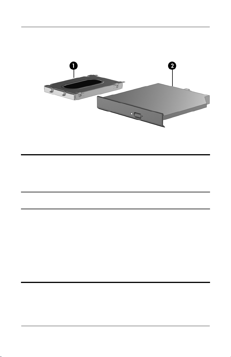
1 Hard drives (include frame and connector)
5400-rpm
80-GB
60-GB
4200-rpm
100-GB
80-GB
60-GB
40-GB
3–10 Maintenance and Service Guide
Number
394358-001
394357-001
394355-001
394354-001
394353-001
394356-001
Page 63

Table 3-2
Mass Storage Devices
Illustrated Parts Catalog
Spare Part Number Information
Item Description
2 Optical drives
For use on HP Special Edition L2000 models
8X Max DVD-ROM drive
24X DVD/CD-RW Combo Drive
8X DVD±RW/R and CD-RW Combo Drive
8X DVD±RW/R and CD-RW Dual Layer Combo Drive,
LightScribe
For use on Compaq Presario V2000 models
8X Max DVD-ROM drive
24X DVD/CD-RW Combo Drive
8X DVD±RW/R and CD-RW Combo Drive
8X DVD±RW/R and CD-RW Dual Layer Combo Drive,
LightScribe
USB digital drive (not illustrated) 364727-001
(Continued)
Spare Part
Number
395728-001
395729-001
395730-001
395731-001
394359-001
394360-001
394362-001
394361-001
Maintenance and Service Guide 3–11
Page 64
Illustrated Parts Catalog
3.4 Miscellaneous Plastics Kit
Miscellaneous Plastics Kit
Table 3-3
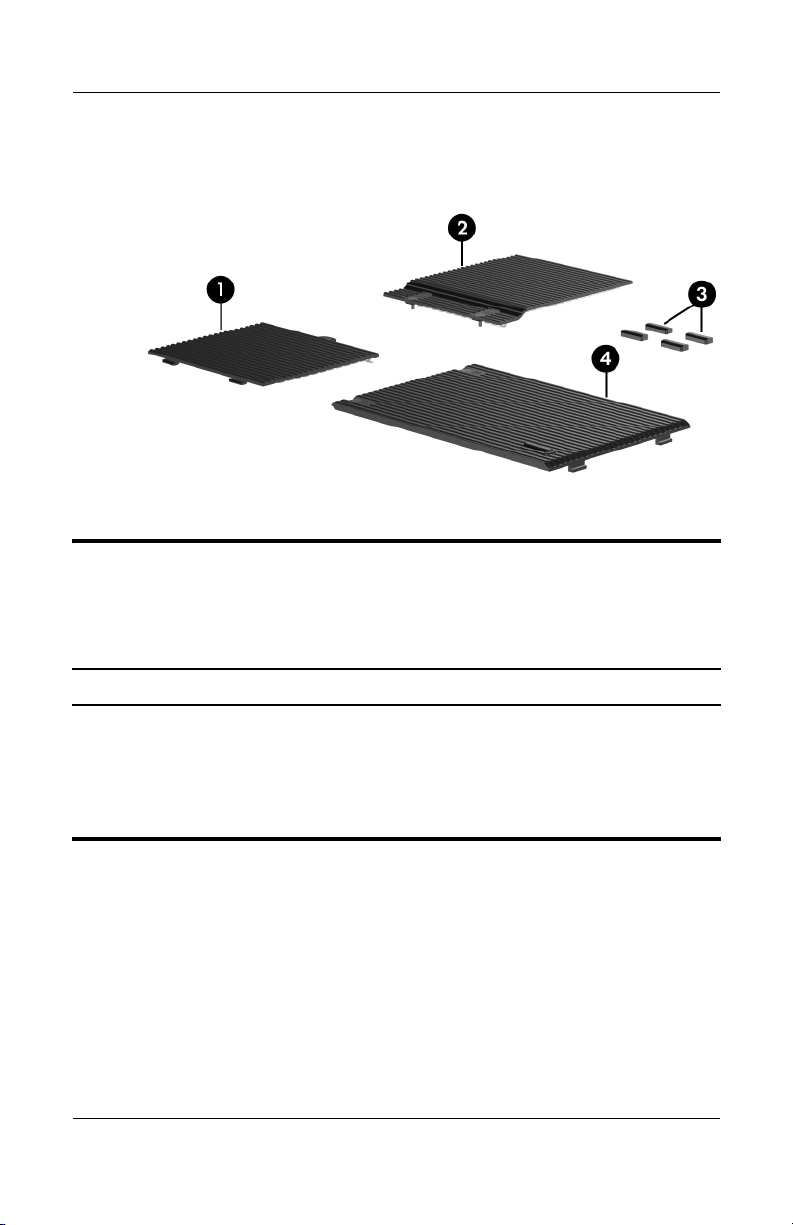
Miscellaneous Plastics Kit
Spare Part Number 394368-001
Item Description
Includes:
1
2
3
4
3–12 Maintenance and Service Guide
Mini PCI compartment cover
Memory module compartment cover
Notebook feet (4)
Hard drive cover
Page 65

3.5 Miscellaneous
Tabl e 3-4
Spare Parts: Miscellaneous (not illustrated)
Description
Logo Kits
Illustrated Parts Catalog
Spare Part
Number
For use on HP Special Edition L2000 models
For use on Compaq Presario V2000 models
Wired headset with volume control
For use on HP Special Edition L2000 models
For use on Compaq Presario V2000 models
All-in-one media cable 375759-001
HP remote control 371694-001
USB travel mouse 309674-001
Notebook entertainment cable and Y-cable 379452-001
65-watt AC adapter 394278-001
Power cord 394279-001
Screw Kit (includes the following screws; refer to Appendix C, “Screw Listing,”
for more information on screw specifications and usage)
For use on HP Special Edition L2000 models
For use on Compaq Presario V2000 models
■ Phillips PM3.0×4.0 screw
■ Phillips PM2.0×6.0 captive screw
(includes C-clips)
■ Phillips PM2.0×6.0 screw
■ Phillips PM2.0×8.0 screw
■ Phillips PM2.0×5.0 screw
■ Phillips PM2.0×4.0 screw
■ Phillips PM1.5×3.5 screw
■ Phillips PM2.0×9.0 captive
spring-loaded, shoulder screw
(includes C-clips)
395370-001
394370-001
371693-002
371693-001
395369-001
394369-001
Maintenance and Service Guide 3–13
Page 66

Illustrated Parts Catalog
3.6 Sequential Part Number Listing
Table 3-5
Spare Parts: Sequential Part Number Listing
Spare Part
Number Description
309674-001 USB travel mouse
364727-001 USB digital drive
371693-001 Wired headset with volume control for use on Compaq
Presario V2000 models
371693-002 Wired headset with volume control for use on HP Special
Edition L2000 models
371694-001 HP remote control
375759-001 All-in-one media cable
379452-001 Notebook entertainment cable and Y-cable
391883-001 6-cell, 4.0-AHr battery pack
394252-001 ATI RS480M system board, for use on defeatured models
(includes disk cell RTC battery)
394253-001 ATI RS480M system board, for use on full-featured models
(includes disk cell RTC battery)
394254-001 Broadcomm Bluetooth WLAN module
394255-001 Mobile AMD Sempron 2800+ (1.6-GHz) processor (includes
thermal pad)
394256-001 Mobile AMD Sempron 3000+ (1.8-GHz) processor (includes
thermal pad)
394257-001 AMD Turion 64 ML-28 (1.6-GHz) processor (includes
thermal pad)
394258-001 AMD Turion 64 ML-30 (1.6-GHz) processor (includes
thermal pad)
3–14 Maintenance and Service Guide
Page 67

Table 3-5
Illustrated Parts Catalog
Spare Parts: Sequential Part Number Listing
Spare Part
Number Description
394259-001 AMD Turion 64 ML-34 (1.8-GHz) processor (includes
thermal pad)
394275-001 12-cell, 8.8-AHr battery pack
394278-001 65-watt AC adapter
394279-001 Power cord
394298-001 Fan (includes heat sink and thermal pad)
394303-001 USB/S-Video controller board (for use on full-featured models)
394347-001 AMD Turion 64 ML-37 (2.0-GHz) processor (includes
thermal pad)
394348-001 14.0-inch, WXGA display assembly for use on Compaq
Presario V2000 models (includes wireless antenna boards
and cables)
394349-001 14.0-inch, WXGA, SVA with Brightview display assembly for
use on Compaq Presario V2000 models (includes wireless
antenna boards and cables)
394350-001 256-MB memory module (333-MHz, DDR1, PC2700)
394351-001 512-MB memory module (333-MHz, DDR1, PC2700)
(Continued)
394352-001 1024-MB memory module (333-MHz, DDR1, PC2700)
394353-001 4200-rpm, 60-GB hard drive (includes frame and connector)
394354-001 4200-rpm, 80-GB hard drive (includes frame and connector)
394355-001 4200-rpm, 100-GB hard drive (includes frame and connector)
394356-001 4200-rpm, 40-GB hard drive (includes frame and connector)
394357-001 5400-rpm, 60-GB hard drive (includes frame and connector)
394358-001 5400-rpm, 80-GB hard drive (includes frame and connector)
Maintenance and Service Guide 3–15
Page 68

Illustrated Parts Catalog
Table 3-5
Spare Parts: Sequential Part Number Listing
Spare Part
Number Description
394359-001 8X Max DVD-ROM drive for use on Compaq Presario V2000
models
394360-001 24X DVD/CD-RW Combo Drive for use on Compaq Presario
V2000 models
394361-001 8X DVD±RW/R and CD-RW Dual Layer Combo Drive,
LightScribe, for use on Compaq Presario V2000 models
394362-001 8X DVD±RW/R and CD-RW Combo Drive for use on Compaq
Presario V2000 models
394363-001 Keyboard for use on Compaq Presario V2000 models in the
United States
394363-121 Keyboard for use on Compaq Presario V2000 models in
French Canada
394365-001 Top cover for use on defeatured Compaq Presario V2000
models (includes TouchPad)
394366-001 Top cover for use on full-featured Compaq Presario V2000
models (includes TouchPad)
394367-001 Base enclosure
(Continued)
394368-001 Miscellaneous Plastics Kit
394369-001 Screw Kit for use on Compaq Presario V2000 models
394370-001 Logo Kit for use on Compaq Presario V2000 models
394371-001 Switch cover for use on Compaq Presario V2000 models with
wireless capability (includes wireless button and light)
394372-001 Switch cover for use on Compaq Presario V2000 models
without wireless capability (includes wireless button and light)
394373-001 Speaker assembly
394374-001 LED board (includes cable)
3–16 Maintenance and Service Guide
Page 69

Table 3-5
Illustrated Parts Catalog
Spare Parts: Sequential Part Number Listing
Spare Part
Number Description
394462-001 Mini PCI 802.11b/g WLAN communications module
395364-001 14.0-inch, WXGA display assembly for use on HP Special
Edition L2000 models (includes wireless antenna boards and
cables)
395365-001 14.0-inch, WXGA, SVA with Brightview display assembly for
use on HP Special Edition L2000 models (includes wireless
antenna boards and cables)
395366-001 Keyboard for use on HP Special Edition L2000 models in the
United States
395368-001 Top cover for use on full-featured HP Special Edition L2000
models (includes TouchPad)
395369-001 Screw Kit for use on HP Special Edition L2000 models
395370-001 Logo Kit for use on HP Special Edition L2000 models
395371-001 Switch cover for use on HP Special Edition L2000 models
395373-001 S-Video controller board (for use on defeatured models)
395728-001 8X Max DVD-ROM drive for use on HP Special Edition L2000
models
395729-001 24X DVD/CD-RW Combo Drive for use on HP Special Edition
L2000 models
(Continued)
395730-001 8X DVD±RW/R and CD-RW Combo Drive for use on
HP Special Edition L2000 models
395731-001 8X DVD±RW/R and CD-RW Dual Layer Combo Drive,
LightScribe, for use on HP Special Edition L2000 models
Maintenance and Service Guide 3–17
Page 70

Illustrated Parts Catalog
Table 3-5
Spare Parts: Sequential Part Number Listing
Spare Part
Number Description
397345-001 Mobile AMD Sempron 3300+ (2.0-GHz) processor (includes
thermal pad)
397346-001 AMD Turion 64 ML-32 (1.8-GHz) processor (includes
thermal pad)
(Continued)
3–18 Maintenance and Service Guide
Page 71

Removal and Replacement
This chapter provides essential information for proper and
safe removal and replacement service.
4.1 Tools Required
You will need the following tools to complete the removal and
replacement procedures:
■ Magnetic screwdriver
■ Phillips P0 screwdriver
■ 2.0-mm hex wrench for processor socket locking screw
■ Flat-bladed screwdriver
■ Tool kit—includes connector removal tool, loopback plugs,
and case utility tool
4
Preliminaries
4.2 Service Considerations
The following sections include some of the considerations
that you should keep in mind during disassembly and assembly
procedures.
As you remove each subassembly from the notebook, place
✎
the subassembly (and all accompanying screws) away from
the work area to prevent damage.
Maintenance and Service Guide 4–1
Page 72

Removal and Replacement Preliminaries
Plastic Parts
Using excessive force during disassembly and reassembly can
damage plastic parts. Use care when handling the plastic parts.
Apply pressure only at the points designated in the maintenance
instructions.
Cables and Connectors
CAUTION: When servicing the notebook, ensure that cables are
Ä
placed in their proper locations during the reassembly process.
Improper cable placement can damage the notebook.
Cables must be handled with extreme care to avoid damage.
Apply only the tension required to unseat or seat the cables
during removal and insertion. Handle cables by the connector
whenever possible. In all cases, avoid bending, twisting, or
tearing cables. Ensure that cables are routed in such a way that
they cannot be caught or snagged by parts being removed or
replaced. Handle flex cables with extreme care; these cables
tear easily.
4.3 Preventing Damage to Removable Drives
Removable drives are fragile components that must be handled
with care. To prevent damage to the notebook, damage to a
removable drive, or loss of information, observe the following
precautions:
■ Before removing or inserting a hard drive, shut down the
notebook. If you are unsure whether the notebook is off or
in hibernation, turn the notebook on, and then shut it down
through the operating system.
■ Before removing a diskette drive or optical drive, ensure that
a diskette or disc is not in the drive and ensure that the optical
drive tray is closed.
4–2 Maintenance and Service Guide
Page 73

Removal and Replacement Preliminaries
■ Before handling a drive, ensure that you are discharged of
static electricity. While handling a drive, avoid touching the
connector.
■ Handle drives on surfaces covered with at least one inch of
shock-proof foam.
■ Avoid dropping drives from any height onto any surface.
■ After removing a hard drive, CD-ROM drive, or a diskette
drive, place it in a static-proof bag.
■ Avoid exposing a hard drive to products that have magnetic
fields, such as monitors or speakers.
■ Avoid exposing a drive to temperature extremes or liquids.
■ If a drive must be mailed, place the drive in a bubble pack
mailer or other suitable form of protective packaging and label
the package, “Fragile: Handle With Care.”
4.4 Preventing Electrostatic Damage
Many electronic components are sensitive to electrostatic
discharge (ESD). Circuitry design and structure determine the
degree of sensitivity. Networks built into many integrated circuits
provide some protection, but in many cases, the discharge
contains enough power to alter device parameters or melt
silicon junctions.
A sudden discharge of static electricity from a finger or other
conductor can destroy static-sensitive devices or microcircuitry.
Often the spark is neither felt nor heard, but damage occurs.
An electronic device exposed to electrostatic discharge might not
be affected at all and can work perfectly throughout a normal
cycle. Or the device might function normally for a while, then
degrade in the internal layers, reducing its life expectancy.
Maintenance and Service Guide 4–3
Page 74

Removal and Replacement Preliminaries
4.5 Packaging and Transporting Precautions
Use the following grounding precautions when packaging and
transporting equipment:
■ To avoid hand contact, transport products in static-safe
containers, such as tubes, bags, or boxes.
■ Protect all electrostatic-sensitive parts and assemblies with
conductive or approved containers or packaging.
■ Keep electrostatic-sensitive parts in their containers until
the parts arrive at static-free workstations.
■ Place items on a grounded surface before removing items
from their containers.
■ Always be properly grounded when touching a sensitive
component or assembly.
■ Store reusable electrostatic-sensitive parts from assemblies
in protective packaging or nonconductive foam.
■ Use transporters and conveyors made of antistatic belts and
roller bushings. Ensure that mechanized equipment used for
moving materials is wired to ground and that proper materials
are selected to avoid static charging. When grounding is not
possible, use an ionizer to dissipate electric charges.
4–4 Maintenance and Service Guide
Page 75

Removal and Replacement Preliminaries
4.6 Workstation Precautions
Use the following grounding precautions at workstations:
■ Cover the workstation with approved static-shielding material
(refer to
■ Use a wrist strap connected to a properly grounded work
surface and use properly grounded tools and equipment.
■ Use conductive field service tools, such as cutters,
screwdrivers, and vacuums.
■ When using fixtures that must directly contact dissipative
surfaces, only use fixtures made of static-safe materials.
■ Keep the work area free of nonconductive materials, such
as ordinary plastic assembly aids and Styrofoam.
■ Handle electrostatic-sensitive components, parts, and
assemblies by the case or PCM laminate. Handle these
items only at static-free workstations.
■ Avoid contact with pins, leads, or circuitry.
■ Turn off power and input signals before inserting or removing
connectors or test equipment.
Table 4-2, “Static-Shielding Materials”).
Maintenance and Service Guide 4–5
Page 76

Removal and Replacement Preliminaries
4.7 Grounding Equipment and Methods
Grounding equipment must include either a wrist strap or a
foot strap at a grounded workstation.
■ When seated, wear a wrist strap connected to a grounded
system. Wrist straps are flexible straps with a minimum of
one megohm ±10% resistance in the ground cords. To provide
proper ground, wear a strap snugly against the skin at all times.
On grounded mats with banana-plug connectors, use alligator
clips to connect a wrist strap.
■ When standing, use foot straps and a grounded floor mat.
Foot straps (heel, toe, or boot straps) can be used at standing
workstations and are compatible with most types of shoes
or boots. On conductive floors or dissipative floor mats, use
foot straps on both feet with a minimum of one megohm
resistance between the operator and ground. To be effective,
the conductive strips must be worn in contact with the skin.
4–6 Maintenance and Service Guide
Page 77

Removal and Replacement Preliminaries
Other grounding equipment recommended for use in preventing
electrostatic damage includes:
■ Antistatic tape
■ Antistatic smocks, aprons, and sleeve protectors
■ Conductive bins and other assembly or soldering aids
■ Nonconductive foam
■ Conductive tabletop workstations with ground cords of
one megohm resistance
■ Static-dissipative tables or floor mats with hard ties to
the ground
■ Field service kits
■ Static awareness labels
■ Material-handling packages
■ Nonconductive plastic bags, tubes, or boxes
■ Metal tote boxes
■ Electrostatic voltage levels and protective materials
Maintenance and Service Guide 4–7
Page 78

Removal and Replacement Preliminaries
Table 4-1 shows how humidity affects the electrostatic voltage
levels generated by different activities.
Tabl e 4-1
Typical Electrostatic Voltage Levels
Relative Humidity
Event 10% 40% 55%
Walking across carpet 35,000 V 15,000 V 7,500 V
Walking across vinyl floor 12,000 V 5,000 V 3,000 V
Motions of bench worker 6,000 V 800 V 400 V
Removing DIPS from plastic tube 2,000 V 700 V 400 V
Removing DIPS from vinyl tray 11,500 V 4,000 V 2,000 V
Removing DIPS from Styrofoam 14,500 V 5,000 V 3,500 V
Removing bubble pack from PCB 26,500 V 20,000 V 7,000 V
Packing PCBs in foam-lined box 21,000 V 11,000 V 5,000 V
A product can be degraded by as little as 700 V.
✎
Table 4-2 lists the shielding protection provided by antistatic
bags and floor mats.
Table 4 -2
Static-Shielding Materials
Material Use Voltage Protection Level
Antistatic plastic Bags 1,500 V
Carbon-loaded plastic Floor mats 7,500 V
Metallized laminate Floor mats 5,000 V
4–8 Maintenance and Service Guide
Page 79

5
Removal and Replacement
Procedures
This chapter provides removal and replacement procedures.
There are as many as 54 screws, in 8 different sizes and types,
that may need to be removed, replaced, or loosened when
servicing the notebook. Make special note of each screw size and
location during removal and replacement.
Refer to Appendix C, “Screw Listing,” for detailed information
on screw sizes, locations, and usage.
Maintenance and Service Guide 5–1
Page 80

Removal and Replacement Procedures
5.1 Serial Number
Report the notebook serial number to HP when requesting
information or ordering spare parts. The serial number is
located on the bottom of the notebook.
Serial Number Location
5–2 Maintenance and Service Guide
Page 81

Removal and Replacement Procedures
5.2 Disassembly Sequence Chart
Use the chart below to determine the section number to be
referenced when removing notebook components.
Disassembly Sequence Chart
Section Description
5.3 Preparing the Notebook
for Disassembly
Battery pack 0
5.4 Hard Drive 2 loosened to remove the hard
5.5 Notebook Feet 0
5.6 Memory Module 2 loosened to remove the
5.7 Mini PCI Communications
Module
To prevent an unresponsive system and the display of a
Ä
warning message, install only a Mini PCI device authorized
for use in your notebook by the governmental agency that
regulates wireless devices in your country. If you install a
device and then receive a warning message, remove the
device to restore notebook functionality. Then contact
Customer Care.
5.8 Optical Drive 1
# of Screws Removed
drive cover
4 removed to disassemble the
hard drive
memory module compartment
cover
1 loosened to remove the
Mini PCI compartment cover
5.9 Switch Cover 2
5.10 Keyboard 4
Maintenance and Service Guide 5–3
Page 82

Removal and Replacement Procedures
Disassembly Sequence Chart
Section Description
5.11 Display Assembly 4
5.12 Base Enclosure 18
5.13 USB/S-Video Controller Board 2
5.14 Bluetooth Module 2
5.15 Speaker Assembly 0
5.16 RTC Battery 0
5.17 Fan Assembly 1 removed, 4 loosened
5.18 Processor 1 loosened
5.19 System Board 4
5.20 LED Board 2
(Continued)
# of Screws Removed
5.3 Preparing the Notebook for Disassembly
Before you begin any removal or installation procedures:
1. Shut down the notebook. If you are unsure whether the
notebook is off or in hibernation, turn the computer on,
and then shut it down through the operating system.
2. Disconnect all external devices connected to the notebook.
3. Disconnect the power cord.
Battery Pack Spare Part Number Information
12-cell, 8.8-AHr
6-cell, 4.4-AHr
5–4 Maintenance and Service Guide
394275-001
391883-001
Page 83

Removal and Replacement Procedures
4. Remove the battery pack by following these steps:
a. Turn the notebook upside down with the front toward you.
b. Slide and hold the battery release latch 1 to the left.
(The front edge of the battery pack disengages from the
notebook.)
c. Lift the front edge of the battery pack 2 and swing
it back.
d. Remove the battery pack.
Removing the Battery Pack
Reverse the above procedure to install the battery pack.
Maintenance and Service Guide 5–5
Page 84

Removal and Replacement Procedures
5.4 Hard Drive
1. Prepare the notebook for disassembly (refer to Section 5.3).
Hard Drive Spare Part Number Information
Include frame and connector.
5400-rpm
80-GB
60-GB
394358-001
394357-001
4200-rpm
100-GB
80-GB
60-GB
40-GB
394355-001
394354-001
394353-001
394356-001
5–6 Maintenance and Service Guide
Page 85

Removal and Replacement Procedures
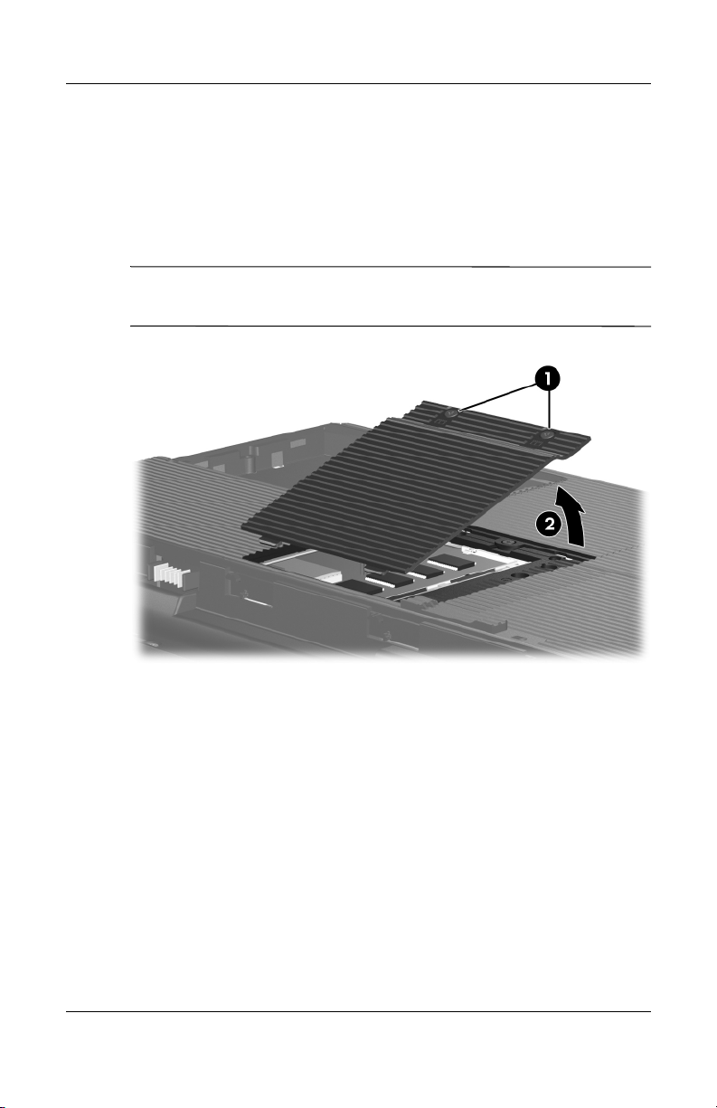
2. Loosen the two PM2.0×6.0 captive screws 1 that secure the
hard drive cover to the notebook.
3. Lift the right side of the cover 2 and swing it to the left.
4. Remove the hard drive cover.
The hard drive cover is included in the Miscellaneous
✎
Plastics Kit, spare part number 394368-001.
Removing the Hard Drive Cover
Maintenance and Service Guide 5–7
Page 86
Removal and Replacement Procedures
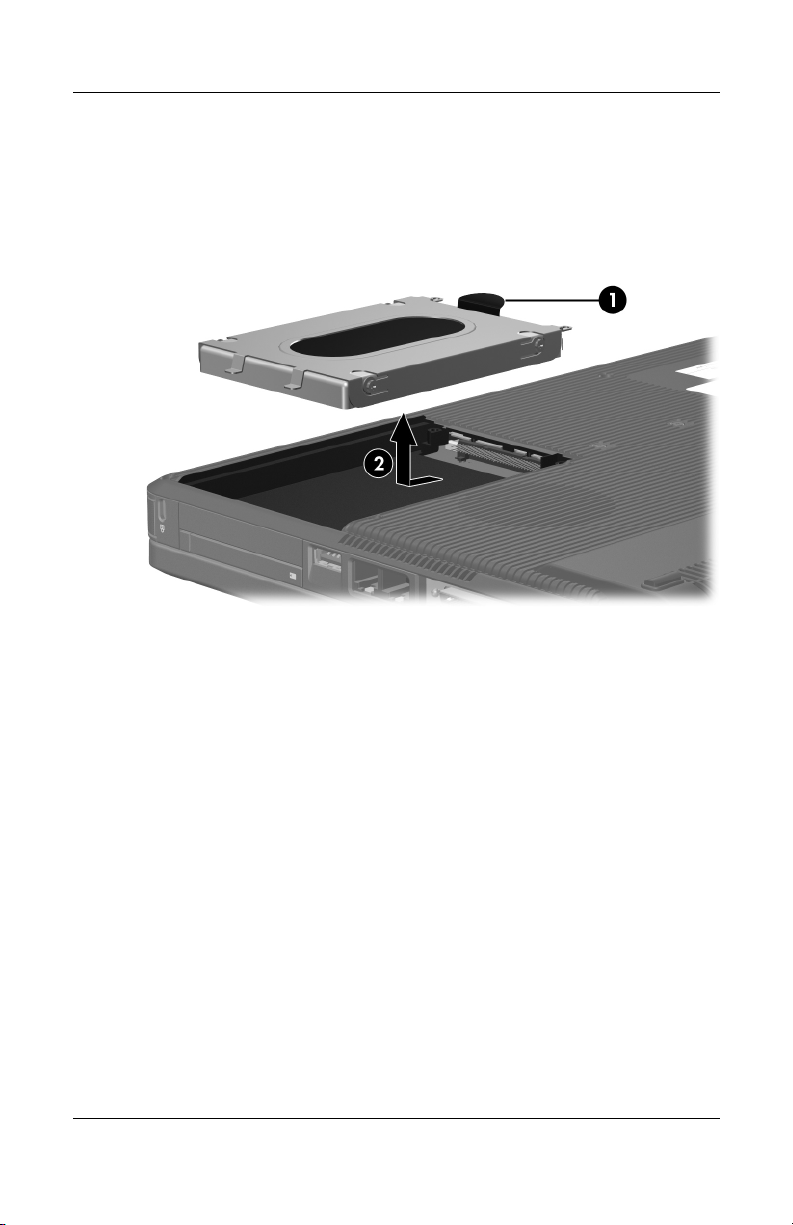
5. Grasp the mylar tab 1 on the hard drive and lift the hard
drive until it disconnects from the notebook.
6. Slide the hard drive 2 to the left and remove it from the hard
drive bay.
Removing the Hard Drive
5–8 Maintenance and Service Guide
Page 87

Removal and Replacement Procedures
7. Remove the four PM3.0×4.0 screws 1 that secure the
hard drive frame to the hard drive.
8. Lift the frame 2 straight up to remove it from the hard drive.
9. Slide the hard drive connector 3 off the hard drive.
Removing the Hard Drive Frame and Connector
Reverse the above procedure to install and reassemble the
hard drive.
Maintenance and Service Guide 5–9
Page 88

Removal and Replacement Procedures
5.5 Notebook Feet
The notebook feet are adhesive-backed rubber pads. The feet are
included in the Miscellaneous Plastics Kit, spare part
394368-001. The feet attach to the base enclosure as illustrated
below.
Replacing the Notebook Feet
5–10 Maintenance and Service Guide
Page 89

5.6 Memory Module
Memory Module Spare Part Number Information
Removal and Replacement Procedures
1024-MB
512-MB
256-MB
394352-001
394351-001
394350-001
1. Prepare the notebook for disassembly (refer to Section 5.3).
2. Position the notebook with the rear panel toward you.
Maintenance and Service Guide 5–11
Page 90
Removal and Replacement Procedures
3. Loosen the two PM2.0×6.0 captive screws 1 that secure the
memory module compartment cover to the notebook.
4. Lift the rear edge of the memory module compartment
cover 2 up, and then swing it forward.
5. Remove the memory module compartment cover.
The memory module compartment cover is included in the
✎
Miscellaneous Plastics Kit, spare part number 394368-001.
Removing the Memory Module Compartment Cover
5–12 Maintenance and Service Guide
Page 91
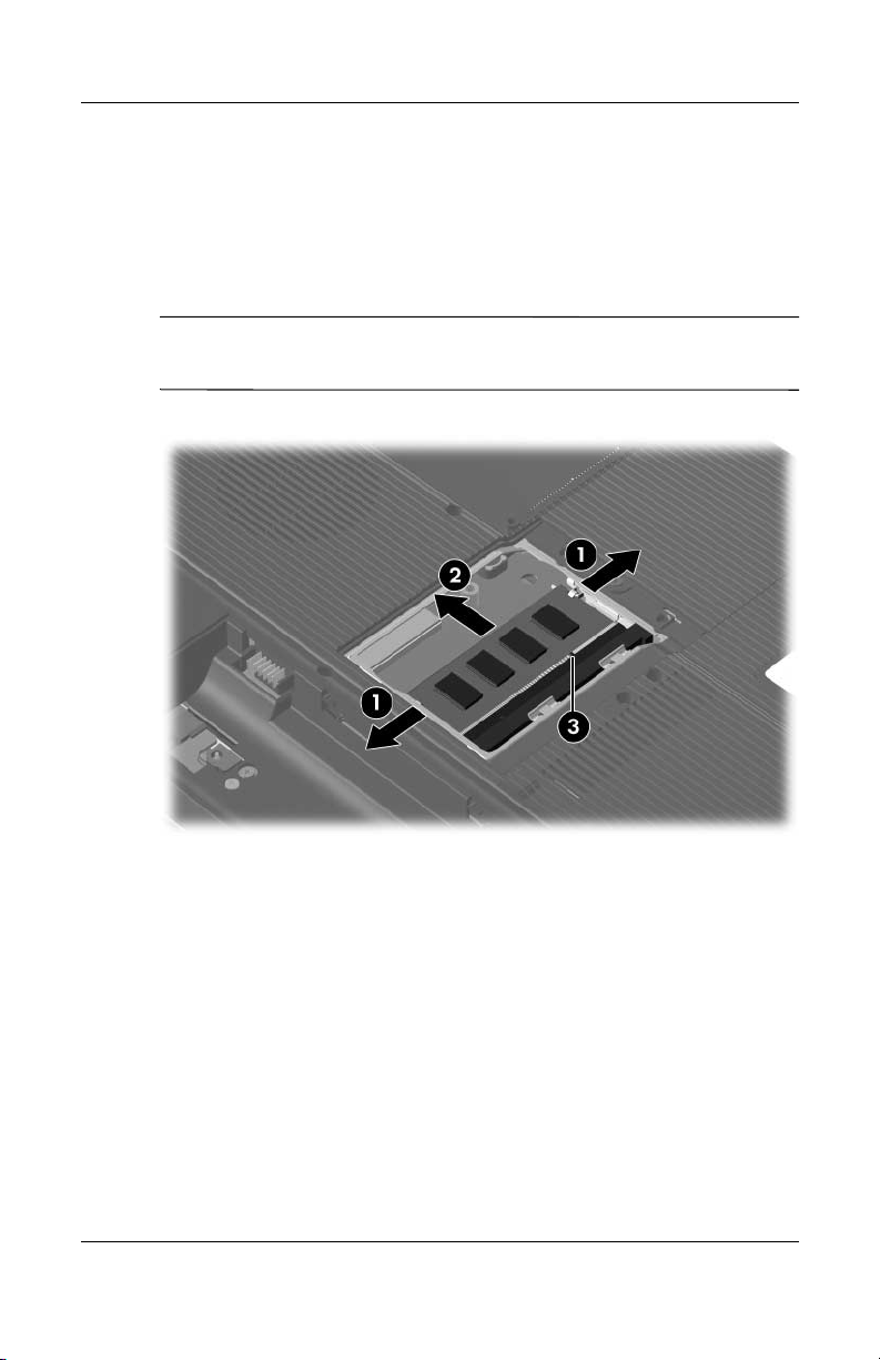
Removal and Replacement Procedures
6. Spread the retaining tabs 1 on each side of the memory
module socket to release the memory module. (The side of
the module opposite the socket rises away from the
notebook.)
7. Slide the module 2 away from the socket at an angle.
Memory modules are designed with a notch 3 to prevent
✎
incorrect installation into the memory module socket.
Removing the Memory Module
Reverse the above procedure to install a memory module.
Maintenance and Service Guide 5–13
Page 92

Removal and Replacement Procedures
5.7 Mini PCI Communications Module
Mini PCI Communications Module
Spare Part Number Information
Mini PCI 802.11b/g WLAN communications module 394462-001
1. Prepare the notebook for disassembly (Section 5.3).
5–14 Maintenance and Service Guide
Page 93
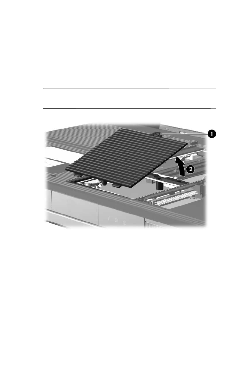
Removal and Replacement Procedures
2. Loosen the PM2.0×6.0 captive screw 1 that secures the Mini
PCI compartment cover to the notebook.
3. Lift the rear edge of the Mini PCI compartment cover 2, and
then swing it forward.
4. Remove the Mini PCI compartment cover.
The Mini PCI compartment cover is included in the
✎
Miscellaneous Plastics Kit, spare part number 394368-001.
Removing the Mini PCI Compartment Cover
Maintenance and Service Guide 5–15
Page 94
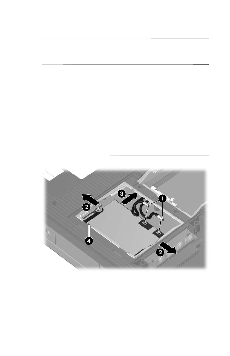
Removal and Replacement Procedures
Make note of which wireless antenna cable is attached to
✎
which antenna clip on the Mini PCI communications module
before disconnecting the cables.
5. Disconnect the wireless antenna cables 1 from the Mini PCI
communications module.
6. Spread the two retaining tabs 2 that secure the Mini PCI
communications module to the communications
compartment socket. (The side of the module opposite the
socket rises up).
7. Remove the wireless communications module 3 by pulling
the module away from the socket at a 45-degree angle.
Wireless communication modules are designed with a notch 4
✎
to prevent incorrect installation into the Mini PCI socket.
Removing a Mini PCI Communications Module
Reverse the above procedure to install a Mini PCI
communications module.
5–16 Maintenance and Service Guide
Page 95

Removal and Replacement Procedures
5.8 Optical Drive
Optical Drive Spare Part Number Information
For use on HP Special Edition L2000 models
8X Max DVD-ROM drive
24X DVD/CD-RW Combo Drive
8X DVD±RW/R and CD-RW Combo Drive
8X DVD±RW/R and CD-RW Dual Layer Combo Drive,
LightScribe
For use on Compaq Presario V2000 models
8X Max DVD-ROM drive
24X DVD/CD-RW Combo Drive
8X DVD±RW/R and CD-RW Combo Drive
8X DVD±RW/R and CD-RW Dual Layer Combo Drive,
LightScribe
1. Prepare the notebook for disassembly (Section 5.3).
395728-001
395729-001
395730-001
395731-001
394359-001
394360-001
394362-001
394361-001
Maintenance and Service Guide 5–17
Page 96

Removal and Replacement Procedures
2. Remove the PM2.0×8.0 screw 1 that secures the optical
drive to the notebook.
3. Insert a thin tool, such as a paper clip 2, into the media tray
release hole. (The optical drive media tray releases from the
optical drive.)
4. Use the media tray frame to slide the optical drive 3 to the
left.
5. Remove the optical drive.
Removing the Optical Drive
Reverse the above procedure to install an optical drive.
5–18 Maintenance and Service Guide
Page 97

5.9 Switch Cover
Switch Cover Spare Part Number Information
Removal and Replacement Procedures
For use on HP Special Edition L2000 models with wireless
capability
For use on HP Special Edition L2000 models without wireless
capability
For use on Compaq Presario V2000 models with wireless
capability
For use on Compaq Presario V2000 models without wireless
capability
1. Prepare the notebook for disassembly (Section 5.3).
2. Remove the two PM2.0×5.0 screws that secure the switch
cover to the notebook.
395371-001
395372-001
394371-001
394372-001
Removing the Switch Cover Screws
Maintenance and Service Guide 5–19
Page 98

Removal and Replacement Procedures
3. Turn the notebook display-side up with the front toward you.
4. Open the notebook as far as possible.
5. Insert a flat-blade screwdriver into the slots located behind
F1, F5, F11, and insert keys 1 and lift up on the front edge
the
of the switch cover 2 until it disengages from the notebook.
6. Remove the switch cover.
Removing the Switch Cover
Reverse the above procedure to install the switch cover.
5–20 Maintenance and Service Guide
Page 99

5.10 Keyboard
Keyboard Spare Part Number Information
Removal and Replacement Procedures
For use on HP Special Edition L2000 models in the
United States
For use on Compaq Presario V2000 models in French Canada 394363-121
For use on Compaq Presario V2000 models in the
United States
395366-001
394363-001
1. Prepare the notebook for disassembly (Section 5.3).
2. Remove the switch cover (Section 5.9).
3. Remove the four PM2.0×4.0 screws that secure the keyboard
to the notebook.
Releasing the Keyboard
Maintenance and Service Guide 5–21
Page 100
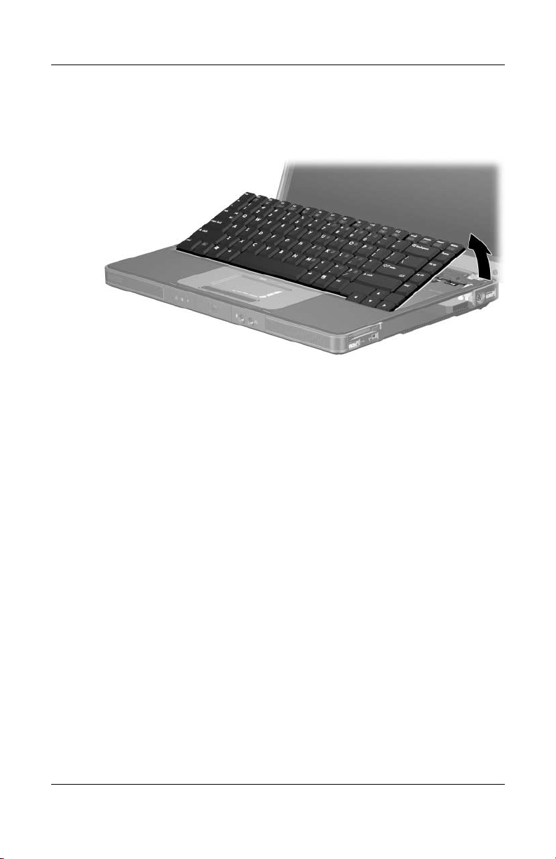
Removal and Replacement Procedures
4. Swing the rear edge of the keyboard up and forward until
it rests on the palm rest.
Releasing the Keyboard
5–22 Maintenance and Service Guide
 Loading...