

Page 1
HP Kayak
PC Workstation
Service Handbook
PC Workstations and
Accessories
4th Edition
June 2000
Page 2
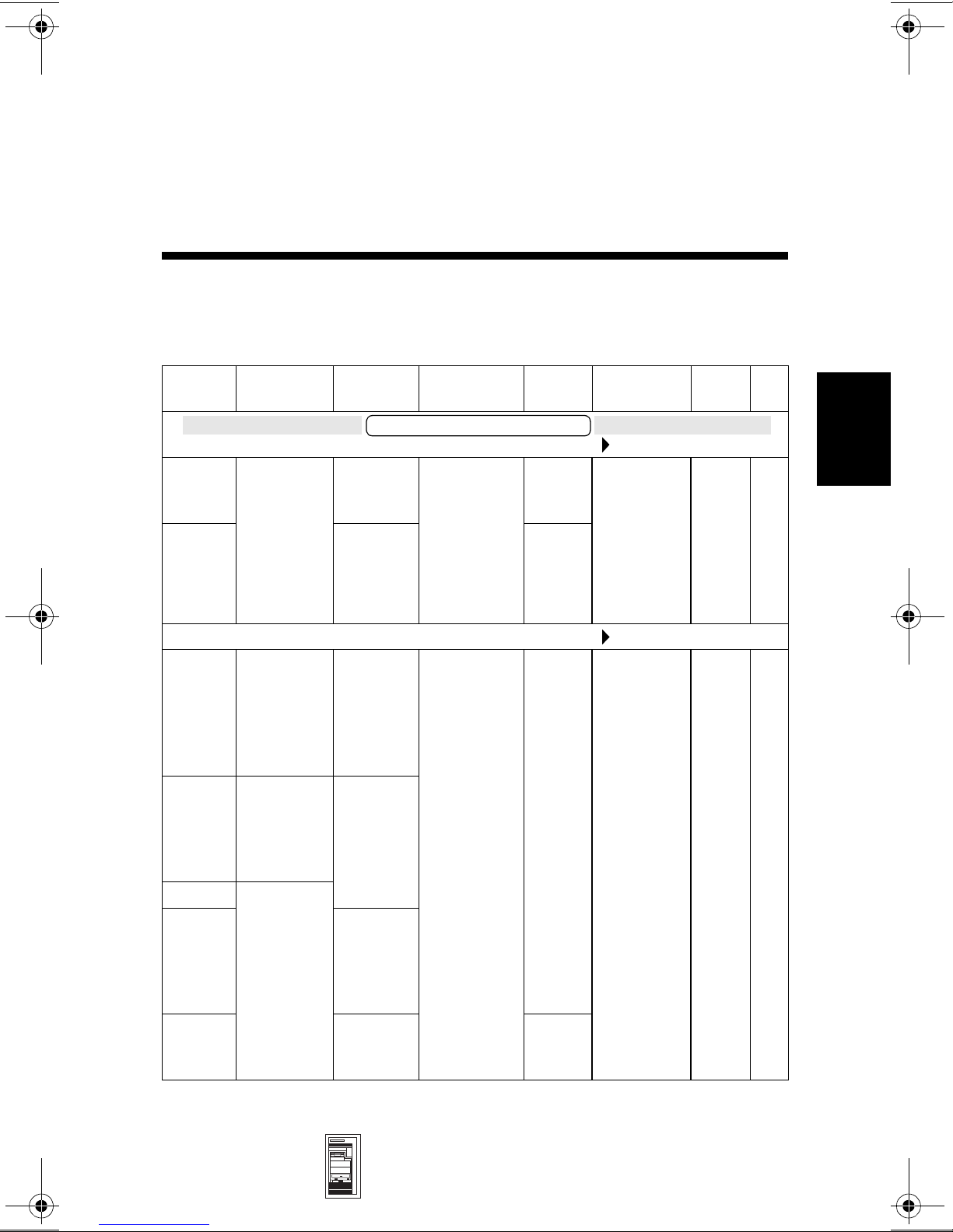
HP Kayak XU (up to 333 MHz) &
HP Kayak XW Series A2, U2, W2
Models and Accessories
4
Product
Number
D4691N Single
D4692N 4.5 GB,
D4693N Single
D4694N Dual
D4695N Single
D4701N 4.5 GB,
D4702N 9.1 GB,
Processors Hard
Drive
HP Kayak XU 6/266 MHz (CPL: 9/97 )
2.1 GB,
Pentium II
with 512 KB
of L2 cache
memory
Pentium II
with 512 KB
of L2 cache
memory
Pentium II
with 512 KB
of L2 cache
memory
Pentium II
with 512 KB
of L2 cache
memory
7.2k rpm,
SCSI
7.2k rpm,
SCSI
HP Kayak XU 6/300 MHz (CPL: 9/97 )
2 x
4.5 GB,
10k rpm,
SCSI with
HP
FastRAID
4.5 GB
10k rpm,
SCSI
10k rpm,
SCSI with
HP
FastRAID
10k rpm,
SCSI
Video
Controller
Kayak XU PC Workstation
Matrox
Millenium II
AGP, 4 MB
on board,
upgradeablet
o 16 MB
Matrox
Millenium II
AGP, 4 MB
on board,
upgradeablet
o 16 MB
Std.
RAM
32 MB
SDRAM
ECC
64 MB
SDRAM
ECC
64 MB
SDRAM
ECC
128 MB
SDRAM
ECC
Multimedia
24✕ IDE
CD-ROM.
Audio chip
(AD1816) is
integrated
on the
system
board.
24✕ IDE
CD-ROM.
Audio chip
(AD1816) is
integrated
on the
system
board.
LAN OS
10BT/
100TX
10BT/
100TX
NT
4.0
WS
NT
4.0
WS
4
Mini-Tower
PC Workstations
HP Kayak XU (up to 333 MHz) & HP Kayak XW
Series A2, U2, W2 4-1
Page 3
HP Kayak XU (up to 333 MHz) & HP Kayak XW Series A2, U2, W2
4
Product
Number
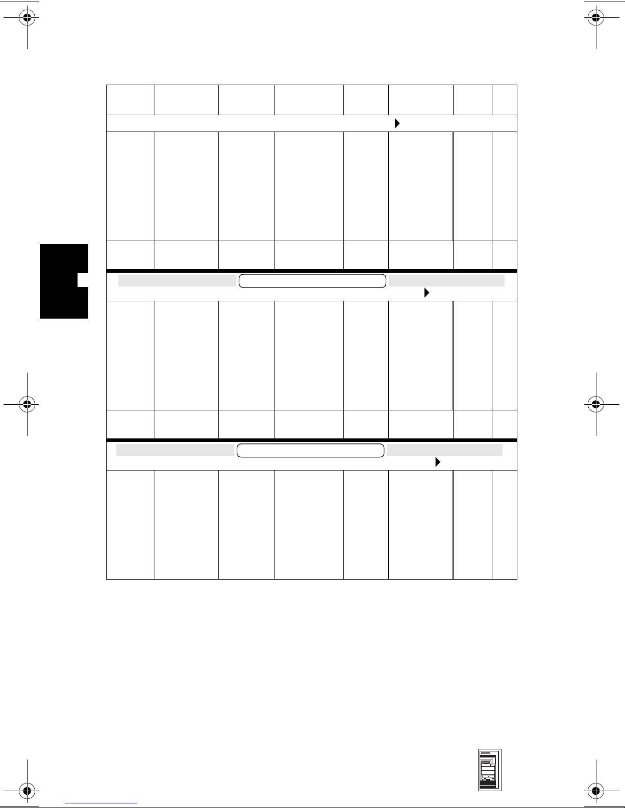
D4705N Single
Product
Number
D6475N Single
Product
Number
D5505N Single
Processors Hard
Pentium II
with 512 KB
of L2 cache
memory
Processors Hard
Pentium II
with 512 KB
of L2 cache
memory
Processors Hard
HP Kayak XW 6/xxx 266 MHz Series U2 (CPL: 10/97 )
Pentium II
with 512 KB
of L2 cache
memory
Video
Drive
HP Kayak XU 6/333 MHz (CPL: 3/98 )
4.5 GB,
10k rpm,
SCSI with
HP
FastRAID
Drive
HP Kayak XW 6/333 MHz Series A2 (CPL: 04/98 )
4.5 GB,
10k rpm,
SCSI
Drive
4.5 GB,
10k rpm,
SCSI
Controller
Matrox
Millenium II
AGP, 4 MB
on board,
upgradeablet
o 16 MB
Video
Controller
Kayak XW Series A2
OpenGL 3D
hardware
accelerator
(Elsa Gloria
Synergy)
Video
Controller
Kayak XW Series U2
OpenGL 3D
hardware
accelerator
(Accel
Graphics,
AccelEclipse
II)
Std.
RAM
64 MB
SDRAM
ECC
Std.
RAM
64 MB
SDRAM
ECC
Std.
RAM
128 MB
SDRAM
ECC
Multimedia
24✕ IDE
CD-ROM.
Audio chip
(AD1816) is
integrated
on the
system
board.
Multimedia
24✕ IDE
CD-ROM.
Audio chip
(AD1816) is
integrated
on the
system
board.
Multimedia
24✕ IDE
CD-ROM.
Audio chip
(AD1816) is
integrated
on the
system
board.
LAN OS
10BT/
100TX
LAN OS
10BT/
100TX
LAN OS
10BT/
100TX
NT
4.0
WS
NT
4.0
WS
NT
4.0
WS
4-2 HP Kayak XU (up to 333 MHz) & HP Kayak XW
Series A2, U2, W2
Mini-Tower
PC Workstations
Page 4
HP Kayak XU (up to 333 MHz) & HP Kayak XW Series A2, U2, W2
Product
Number
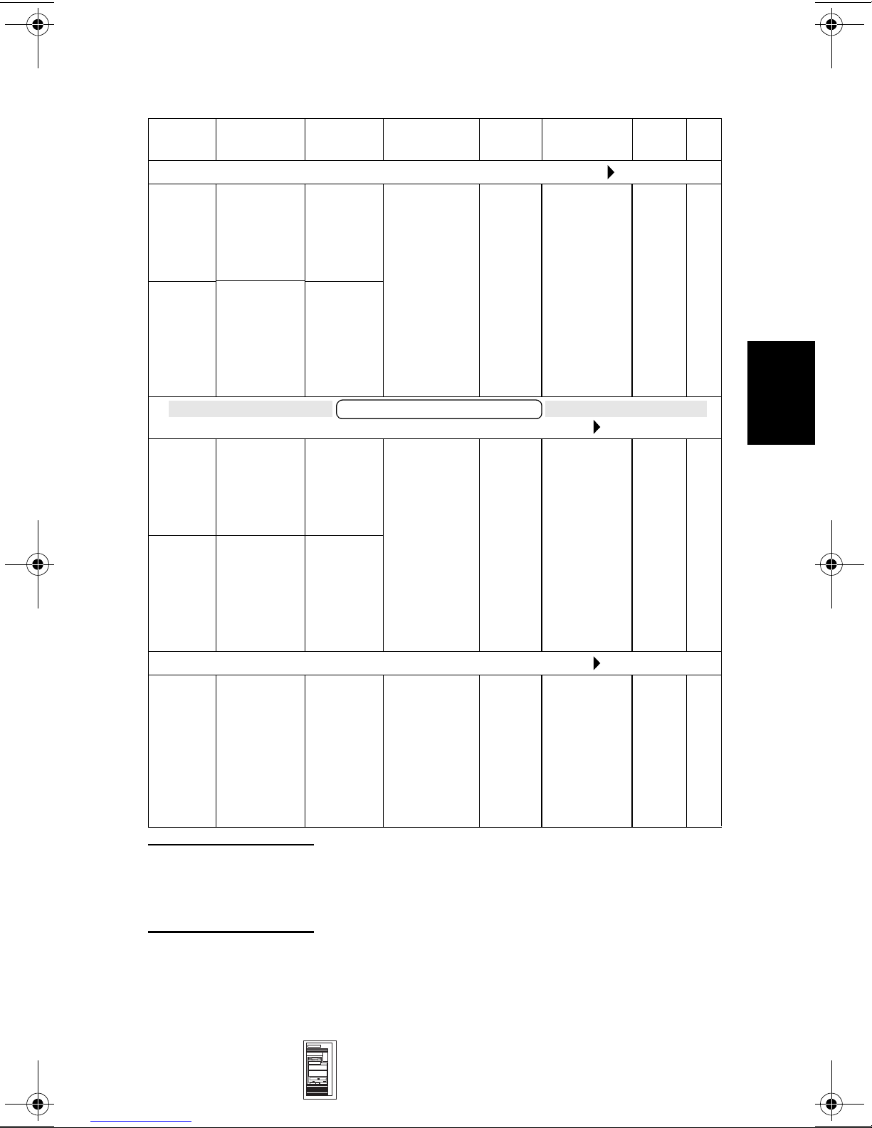
D5507N Single
D5509N Dual
D5510N Single
D5514N Dual
D6485N Single
Processors Hard
HP Kayak XW 6/xxx 300 MHz Series U2 (CPL: 10/97 )
Pentium II
with 512 KB
of L2 cache
memory
Pentium II
with 512 KB
of L2 cache
memory
Pentium II
with 512 KB
of L2 cache
memory
Pentium II
with 512 KB
of L2 cache
memory
Pentium II
with 512 KB
of L2 cache
memory
Video
Drive
9.1 GB,
10k rpm,
SCSI with
HP
FastRAID
2 x
4.5 GB,
10k rpm,
SCSI with
HP
FastRAID
HP Kayak XW 6/300 MHz Series W2 (CPL: 10/97 )
4.5 GB,
10k rpm,
SCSI
2 x
4.5 GB,
10k rpm,
SCSI with
HP
FastRAID
HP Kayak XW 6/333 MHz Series W2 (CPL: 10/97 )
4.5 GB,
10k rpm,
SCSI
Controller
OpenGL 3D
hardware
accelerator
(Accel
Graphics,
AccelEclipse
II)
Kayak XW Series W2
OpenGL 3D
hardware
accelerator
(HP
VISUALIZE
fx4)
OpenGL 3D
hardware
accelerator
(HP
VISUALIZE
fx4)
Std.
RAM
128 MB
SDRAM
ECC
128 MB
SDRAM
ECC
128 MB
SDRAM
ECC
Multimedia
24✕ IDE
CD-ROM.
Audio chip
(AD1816) is
integrated
on the
system
board.
24✕ IDE
CD-ROM.
Audio chip
(AD1816) is
integrated
on the
system
board.
24✕ IDE
CD-ROM.
Audio chip
(AD1816) is
integrated
on the
system
board.
LAN OS
10BT/
100TX
10BT/
100TX
10BT/
100TX
NT
4.0
WS
NT
4.0
WS
NT
4.0
WS
4
NOTE: All models are supplied with a 1.44 MB (D2035B)
Mini-Tower
PC Workstations
Flexible Disk Drive, two integrated SCSI controllers
(one Ultra Wide 16-bit SCSI and one Ultra Narrow 8-bit
SCSI), and an integrated IDE controller.
HP Kayak XU (up to 333 MHz) & HP Kayak XW
Series A2, U2, W2 4-3
Page 5

HP Kayak XU (up to 333 MHz) & HP Kayak XW Series A2, U2, W2
Supported Accessories
Memory Upgrades
32 MB ECC SDRAM upgrade kit D5365A
64 MB ECC SDRAM upgrade kit D5366A
128 MB ECC SDRAM upgrade kit D5367A
Video Memory
4 MB memory upgrade for Matrox Millenium II AGP video controller—
HP Kayak XU PC Workstation only
Hardware texture accelerator with 16 MB SDRAM dedicated texture
memory—HP Kayak XW PC Workstation Series W2 only
D5487A
D5511A
4
Dual Processor Kits
Pentium II 266 MHz containing 512 KB internal L2 cache D5483A
Pentium II 300 MHz containing 512 KB internal L2 cache D5484A
Pentium II 333 MHz containing 512 KB internal L2 cache D6526A
Input Devices
HP mouse C3751B
HP scrolling mouse C4736A
Video Displays
All current HP Displays (see the HP Kayak Accessory Service Handbook)
Mass Storage—Hard disk drives
4.5 GB UW-SCSI hard disk 7.2k rpm D5368A/B
4.5 GB UW-SCSI hard disk 10k rpm D5481A
9.1 GB UW-SCSI hard disk 7.2k rpm (1.6-inch high)
9.1 GB UW-SCSI hard disk 10k rpm (1-inch high) D6520A
Removable Mass Storage
Flexible disk 3.5-inch 1.44 MB (1-inch high) D2035B
IDE 24✕ CD-ROM drive D4383A/B
3.5-inch device rail kit (pack of 5) D3566A
5.25-inch device rail kit (pack of 5) 5063-7961
IDE 24✕ CD-ROM drive (pack of 10) D6506A
HP SureStore CD-RW drive—HP Kayak XW Series A2 only D4353A
100 MB internal Iomega ZIP drive—HP Kayak XW Series A2 only D4390A
1
2
D5369A
4-4 HP Kayak XU (up to 333 MHz) & HP Kayak XW
Series A2, U2, W2
Mini-Tower
PC Workstations
Page 6

HP Kayak XU (up to 333 MHz) & HP Kayak XW Series A2, U2, W2
Miscellaneous
HP FastRAID Accessory Kit D5480A
User’s Guide Manual Kit—
HP Kayak XU PC Workstation Series (up to 333 MHz) D4700A
HP Kayak XW PC Workstation Series A2, U2, W2 D5518A
Multimedia
HP Kayak XW Series A2 only
Multimedia Sound accessory kit (24✕ max-speed IDE CD-ROM drive and
16-bit PnP audio board)
HP Audio kit (16-bit PnP audio board, pack of 10) D5183A
D5182A/B
1. Dual Processor Kits include: processor, voltage regulator module and heatsink.
2. Only one 1.6-inch hard disk drive is supported in both the Kayak XU and XW PC
Workstation (on the lower internal shelf).
4
Mini-Tower
PC Workstations
HP Kayak XU (up to 333 MHz) & HP Kayak XW
Series A2, U2, W2 4-5
Page 7
HP Kayak XU (up to 333 MHz) & HP Kayak XW Series A2, U2, W2
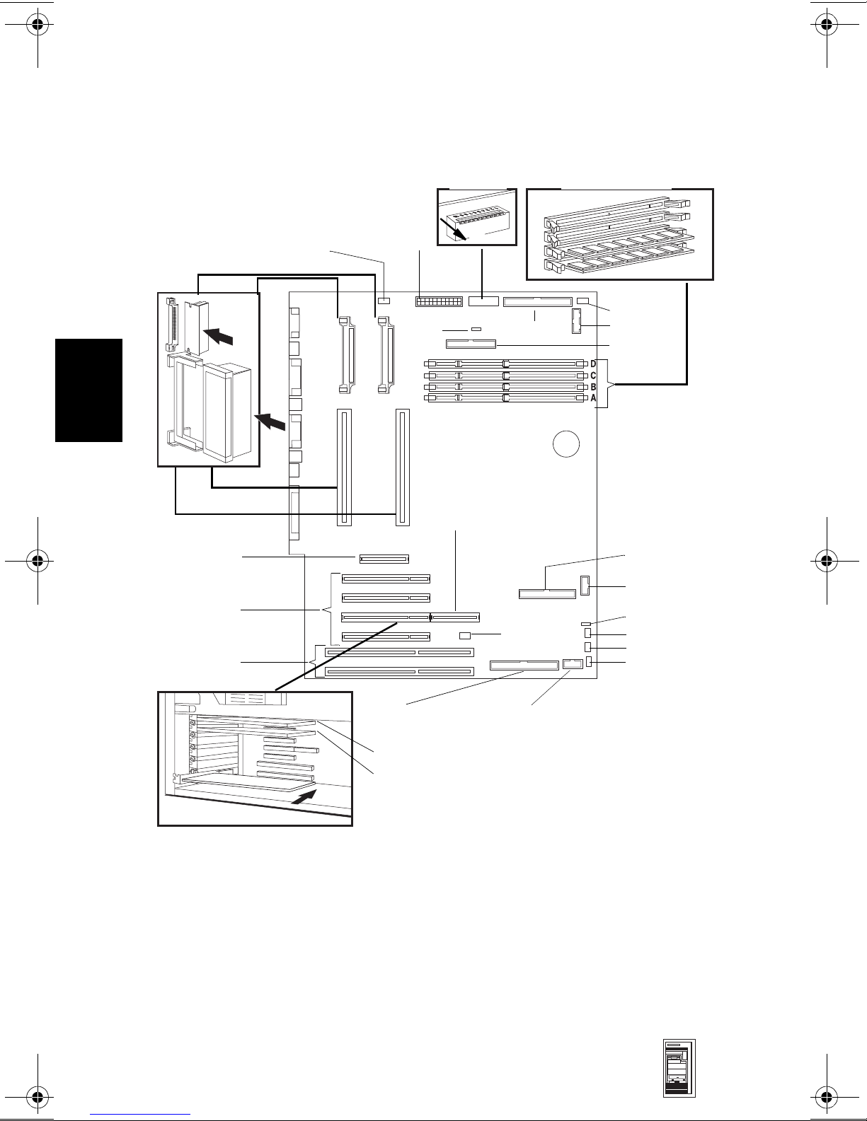
System Board, BIOS and Memory
4
VRM 1 VRM 2
Processor 1
Processor 2
AGP Slot
PCI Slots
ISA Slots
Fan
(airflow guide)
Power
External
Battery
Switches
RAIDport
UP
16-bit SCSI
Fan
Memory Modules
Fan
Status Panel
FDD
IDE Connector
External Start
Internal speaker
AUX
CD
Audio Front Panel
Microphone
4-6 HP Kayak XU (up to 333 MHz) & HP Kayak XW
Series A2, U2, W2
8-bit SCSI
Video Board
LAN Board
Multimedia Front Panel Connector
(Headphone Out and Volume Control)
Mini-Tower
PC Workstations
Page 8
HP Kayak XU (up to 333 MHz) & HP Kayak XW Series A2, U2, W2
System Board Switches
Switch Function Default
1-5 — Processor frequency, see following table —
1
6UP
DOWN Clears EEPROM
7 UP Enables User and Administrator passwords
DOWN Clears User and Administrator passwords
8 UP Disables power on using keyboard
DOWN Enables keyboard power on
9
10 UP Normal operation
1. UP=OFF, DOWN=ON (refer to the diagram on page 6 of this chapter for switch
2. Refer to “Recovery Boot Active Procedure” in Appendix B for the detailed recovery
UP
DOWN Fan speed set at maximum.
DOWN Recovery boot active (force BIOS flashing)
positioning).
procedure.
Retain configuration in EEPROM, normal position
Fan speed controlled by internal temperature
sensors.
2
UP
UP
DOWN
UP
UP
4
Switch
12345
2
UP
UP UP
UP DOWN UP DOWN UP 300 MHz
UP DOWN UP UP DOWN 333 MHz
1. PL Bus Frequency is 66 MHz
2. UP=OFF, DOWN=ON (refer to the diagram on page 6 of
UP DOWN DOWN DOWN 233 MHz
DOWN UP UP 266 MHz
PCI Bus Frequency is 33 MHz
ISA Bus Frequency is 8.25 MHz
this chapter for switch positioning).
Processor
Frequency
1
Setup and BIOS History
For the latest BIOS, the flasher utility program, and the BIOS history refer to the
HP World Wide Web site. The BIOS is in the form HB1xxxyy.FUL, where xxx is
the version number and yy is the language number.
http://www.hp.com/go/kayaksupport
Mini-Tower
PC Workstations
HP Kayak XU (up to 333 MHz) & HP Kayak XW
Series A2, U2, W2 4-7
Page 9
4
HP Kayak XU (up to 333 MHz) & HP Kayak XW Series A2, U2, W2
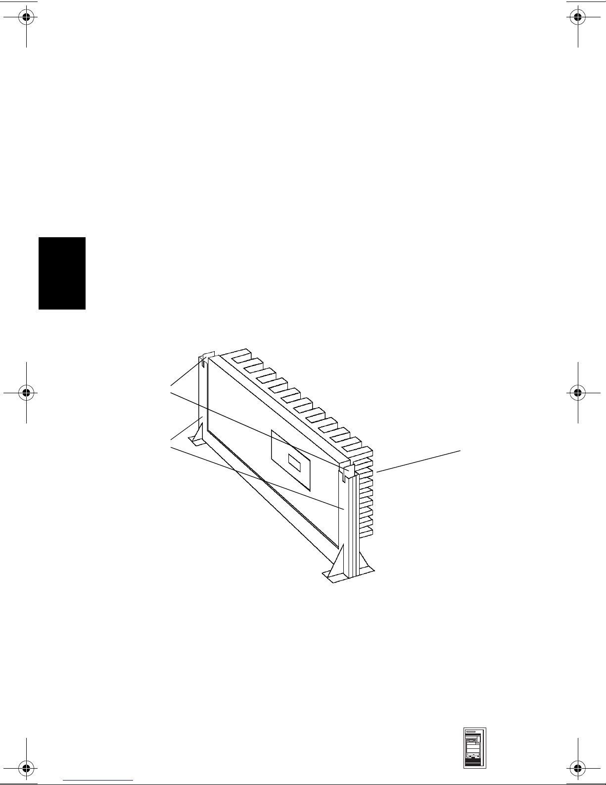
Installing a Dual Processor / Replacing a processor
HP Kayak XU and XW 6/xxx PC Workstations are supplied with dual processor
slots and either one or two processors installed. Single processor models can be
upgraded to dual processor systems by installing the second processor
accessory in the vacant slot.
The second processor must be a Pentium II processor of the same speed and
level-2 cache memory capacity as the first. It is installed by gently sliding the
processor into the vacant processor connector slot until the two plastic clips at
the sides engage to lock the processor into place.
Every processor that is installed, or replaced, must be accompanied by the
voltage regulator module (VRM) that was supplied with it. Each VRM is specific
to the processor with which it was supplied, and should only be used with that
processor.
After installation of a second processor, the operating system must be
reinstalled.
Plastic clips
Bracket pillars
Heat-sink
Cache Memory
512 KB of level-two cache memory is integrated in the Pentium II processor
package.
4-8 HP Kayak XU (up to 333 MHz) & HP Kayak XW
Series A2, U2, W2
Mini-Tower
PC Workstations
Page 10

HP Kayak XU (up to 333 MHz) & HP Kayak XW Series A2, U2, W2
Main Memory
The PC Workstation has four DIMM slots on the system board for installing
main memory; slots A, B, C and D.
Models are supplied with 32, 64 or 128 MB of main memory. If additional
memory is required, up to 512 MB may be installed. Memory upgrades are
available in single 32 MB, 64 MB or 128 MB ECC SDRAM modules. A serial
EEPROM on the DIMM contains data on the memory speed. This information is
read at each power on, and access time settings are set accordingly.
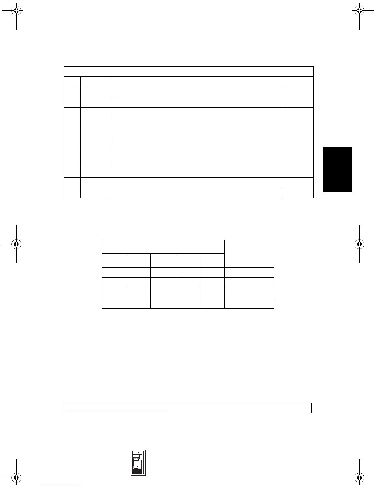
Millennium II Video Memory (HP Kayak XU)
There is 4 MB of video memory already supplied on the graphics controller
board. Memory may be upgraded to a maximum of 16 MB by installing a
memory module of 4 MB, 8 MB or 12 MB onto the board. No switch or jumper
settings need to be changed (all jumpers should be left in the positions in which
they were set by the manufacturer).
AccelEclipse Video Memory (HP Kayak XW Series U2)
4
There is a total of 32 MB of memory, already supplied on the graphics controller
board. There are no upgrades possible, and no switch or jumper settings to be
changed (all jumpers should be left in the positions in which they were set by
the manufacturer).
In case of failure, the whole video board has to be replaced. The replacement
video board is supplied with 32 MB of memory.
PCI bus connector
Cooling fan
Daughter board
Daughter board
Display connector
Mini-Tower
PC Workstations
HP Kayak XU (up to 333 MHz) & HP Kayak XW
Series A2, U2, W2 4-9
Page 11

4
HP Kayak XU (up to 333 MHz) & HP Kayak XW Series A2, U2, W2
VISUALIZE Fx4 Video Memory (HP Kayak XW Series W2)
The texture mapping board is available as an accessory for the HP VISUALIZE
fx4 OpenGL interface board.
1 Remove the HP VISUALIZE fx4 board from the HP Kayak XW.
2 Remove the four screws from the blank board, then remove the board.
3 Remove the terminator from the HP VISUALIZE fx4 board.
The terminator, or ridge
line connector, has part
number A4554-40001.
4-10 HP Kayak XU (up to 333 MHz) & HP Kayak
XW Series A2, U2, W2
Mini-Tower
PC Workstations
Page 12

HP Kayak XU (up to 333 MHz) & HP Kayak XW Series A2, U2, W2
4 Very carefully install the texture mapping board on the HP VISUALIZE fx4
board.
5 Replace the four screws in the texture mapping board.
4
6 Replace the HP VISUALIZE fx4 board in the HP Kayak XW.
NOTE: To support this texture module an up to date OpenGL
driver is required.
Mini-Tower
PC Workstations
HP Kayak XU (up to 333 MHz) & HP Kayak XW
Series A2, U2, W2 4-11
Page 13

4
HP Kayak XU (up to 333 MHz) & HP Kayak XW Series A2, U2, W2
Part Numbers
4-12 HP Kayak XU (up to 333 MHz) & HP Kayak
XW Series A2, U2, W2
Mini-Tower
PC Workstations
Page 14

HP Kayak XU (up to 333 MHz) & HP Kayak XW Series A2, U2, W2
Parts List
Item Description Repl.
Part Number
1 Box assembly:
a I/O Guide + Fan + Speaker assembly
b Cover lock assembly
c Status panel kit
d Multimedia control panel
e Bumper foot
2 Logo HP Kayak XU PC Workstation
Logo HP Kayak XW
3 Filler panel 3.5-inch 5042-1405 —
4 Filler panel 5.25-inch 5042-1178 —
5 Multimedia bezel 5042-2452 —
6 Upper Front Fan 5064-3352 —
UW-SCSI Hard disk drive
7
2.1 GB, 7.2k rpm
4.5 GB, 7.2k rpm
4.5 GB, 10k rpm
9.1 GB, 7.2k rpm
9.1 GB, 10k rpm
8 5.25-inch tray 5002-1946 —
9 3.5-inch tray Part of Box Assembly
10 Power supply unit 0950-3212 —
11 Flexible disk drive D2035-60152 —
12 CD-ROM drive (standard):
24✕ IDE D4383-63001 D4383-69001
13 Rail kit (3.5-inch) D3566A —
14 Rail kit (5.25-inch) 5063-7961 —
15 Internal ATA33 IDE cable
16 Headset 5064-2673 —
17 CD-ROM to audio cable
18 Airflow guides:
a) Rear fan + Airflow guide assembly
b) Processor Retainer Airflow guide
19 Flexible disk cable 5183-0746 —
20 System board See system board parts list
(standard)1:
2
(for CD-ROM) 5183-2708 —
5064-1860
5063-3351
5062-5590
5064-3353
5064-1832
5042-2479
5042-2428
5042-1862
D5140-63001
D5141-63001
D4625-63001
D4629-63001
D4627-63001
5182-1857
5064-3316
5042-2427
Part Number
—
—
—
—
—
—
—
—
D5140-69001
D5141-69001
D4625-69001
D4629-69001
D4627-69001
—
—
—
Exchange
4
Mini-Tower
PC Workstations
HP Kayak XU (up to 333 MHz) & HP Kayak XW
Series A2, U2, W2 4-13
Page 15

HP Kayak XU (up to 333 MHz) & HP Kayak XW Series A2, U2, W2
Parts List
4
Item Description Repl.
Part Number
21 Graphics board:
Millennium II AGP (4 MB)
4 MB Memory upgrade kit
Elsa Gloria Synergy —
XW Series A2 (not shown)
Accel Graphics AccelEclipse —
XW Series U2 (shown on page 4-9)
HP VISUALIZE fx4 —
XW Series W2 (shown on page 4-10)
Texture mapping board with 16 MB
SDRAM dedicated texture memory
Loopback connector/ridge line
connector
22 HP 10/100 BT PCI -LAN board 5064-1897 D3999-69001
23 SCSI cables (including SCSI terminator)
a) 8-bit SCSI
b) 16-bit SCSI
24 Processor terminator 5064-2680 —
25 3-button mouse C4728-60101 —
26 FastRAID (Adaptec ARO) card with
SIMM 16 MB memory
27 CPU guide 5042-0569 —
28 Internal LAN cable 5183-0758 —
Not
Shown
Keyboards
Enhanced keyboard
Windows 95 keyboard - Japan
Windows 95 keyboard - Korea
I/O blank panel 45935-00004 —
3
5064-1873
D5487-63001
5064-3366
5064-3362
064-3301
5064-3323
A4554-40001
5183-0747
5183-2765
5064-1874 D4580-69001
C4734-601xx
C4729-60224
C4730-60121
4
Exchange
Part Number
D4690-69501
—
D6475-69501
D5505-69501
D5510-69501
D5511-69501
—
—
—
—
—
1. For optional disk drive information, refer to the Accessory Service Handbook.
2. This is a specific IDE cable with the master connector on one end and the slave connector
in the middle of the IDE cable.
3. Refer to the diagram on page 4-10.
4. Where “xx” is the code for your national keyboard, refer to the Accessory Service
Handbook.
4-14 HP Kayak XU (up to 333 MHz) & HP Kayak
XW Series A2, U2, W2
Mini-Tower
PC Workstations
Page 16

HP Kayak XU (up to 333 MHz) & HP Kayak XW Series A2, U2, W2
System Board Parts List
Description Repl.
Part Number
System board:
1
Processors
Intel Pentium II 266 MHz, 512 KB cache 5064-2652 —
Intel Pentium II 300 MHz, 512 KB cache 5064-3330 —
Intel Pentium II 333 MHz, 512 KB cache 5064-3697 D6526-69001
Voltage regulator module (VRM) 0950-3310 —
Main memory modules:
1 ✕ 32 MB main memory ECC SDRAM
1 ✕ 64 MB main memory ECC SDRAM
1 ✕ 128 MB main memory ECC SDRAM
1. Heat-sink is integrated in the Pentium II processor package.
:
D4690-63001 D4690-69001
D5365-63001
D5366-63001
D5367-63001
Exchange
Part Number
D5365-69001
D5366-69001
D5367-69001
Manuals and Documentation
User’s Guide:
HP Kayak XU PC Workstation
HP Kayak XW PC Workstation Series A2, U2, W2
Familiarization Guide:
HP Kayak XU PC Workstation
HP Kayak XW PC Workstation Series A2, U2, W2
Technical Reference Manual
D4700-90001 and
electronic file
D5518-90001 and
electronic file
D4700-90901—
electronic file
D5518-9000—
electronic file
electronic file only
4
Kayak XU and XW Drivers and documentation CD-ROM 5011-5261
Mini-Tower
PC Workstations
Software
HP Kayak XU (up to 333 MHz) & HP Kayak XW
Series A2, U2, W2 4-15
Page 17

4
HP Kayak XU (up to 333 MHz) & HP Kayak XW Series A2, U2, W2
Notes: _____________________________________________________________
____________________________________________________________________
____________________________________________________________________
____________________________________________________________________
____________________________________________________________________
____________________________________________________________________
____________________________________________________________________
____________________________________________________________________
____________________________________________________________________
____________________________________________________________________
____________________________________________________________________
____________________________________________________________________
____________________________________________________________________
____________________________________________________________________
____________________________________________________________________
____________________________________________________________________
____________________________________________________________________
____________________________________________________________________
4-16 HP Kayak XU (up to 333 MHz) & HP Kayak
XW Series A2, U2, W2
Mini-Tower
PC Workstations
Page 18

A
Beep, POST, and Error Codes
Beep Codes
If an error occurs during the POST, which prevents the PC Workstation from
starting, and before the display device has been initialized, a series of beep
codes are issued. Beep codes indicate that a fatal error has occurred and can be
reported one after another if there is more than one detected error. In this case,
the first detected error is the most important.
These codes are useful for identifying the error when the system is unable to
display the error message.
A
Beep, POST, and Error Codes A-1
Page 19

A
Beep Codes for the HP Kayak XU800
Number
of
Beeps
1 The memory refresh
2 Parity error in the base
3 Memory error.
4 Clock error. • Check that the system board is correctly
5 Processor test error. Check that:
Description Action to Take...
Check that:
circuitry is faulty.
memory (the first 64 KB
block) of memory.
• Memory is installed correctly.
• Correct memory modules are being used.
If the error still occurs, replace the memory.
cabled (power cables, processor and
terminator).
If the error still occurs, replace the system
board.
• Processor is correctly installed.
• Termination card installed in processor
slot 2 in a single processor system.
If the error still occurs, replace:
1Processor.
2 system board.
6 Input/Output (I/O) error. • Keyboard is connected.
• PCI card is installed correctly.
• Termination card installed in processor
slot 2 in a single processor system.
7 The processor on the
system board generated
an error.
8 The system video card is
either missing or faulty.
• There is an installed processor(s).
• Processor(s) is correctly installed in the
processor slot(s).
• Two installed processors have the same
cache size (256 k).
• Termination card is installed in processor
slot 2 in a single processor system.
• VRM is installed in the VRM socket in a
dual processor system.
If the error still occurs, replace the system
board.
This is not a fatal error. Check that the video
card is correctly installed and cabled. If
missing, install the video card. If the error
still occurs, replace it with a known working
video card.
A-2 Beep, POST, and Error Codes
Page 20

A
Number
of
Beeps
9 The BIOS Checksum
10 The CMOS RAM has
11 The cache memory test
Description Action to Take...
value does not match the
value encoded in the
BIOS.
failed.
failed.
Perform the following actions in this order:
1Press F2 to enter the Setup program,
then F9 to load the default BIOS settings.
2 Clear the CMOS.
3 Flash the BIOS.
If the error still occurs, replace the system
board.
Perform the following actions in this order:
1Press F2 to enter the Setup program,
then F9 to load the default BIOS settings.
2 Clear the CMOS.
3 Flash the BIOS.
If the error still occurs, replace the system
board.
Replace the processor(s).
Beep, POST, and Error Codes A-3
Page 21

A
Beep Codes for the HP Kayak XM600
Beep
Pattern
— - - - - - - -
— - - - — —
— - - - — - - -
— - - - - - - —
— - - - - - - - —
— - - - - - - - - - -
— - - - - — —
- - — - - - - -
- - - - - - - —
Beep
Code
1-2-2-3 16h
1-3-1-1 20h
1-3-1-3 22h
1-3-3-1 28h
1-3-4-1 2Ch
1-3-4-3 2Eh
1-4-1-1 30h
2-1-2-3 46h
2-2-3-1 58h
Numeric
Code
Description Recommended
Action
BIOS ROM
check-sum
failure
DRAM refresh
test failure1
8042
Keyboard
controller test
failure
Initialization
of RDRAM
has failed.
RAM failure
on address
1
....
line
RAM failure
on data bits
....of low byte
of memory
bus1
RAM failure
on data bits
....of high byte
of memory
bus1
ROM
copyright
notice check
failure
Unexpected
interrupts test
failure
Inform HP support/HP reseller
that system board is defective.
Check the memory is correctly
installed. If the error still occurs,
replace the module.
Inform HP support/HP reseller
that system board is defective.
Verify that memory or continuity
modules are installed.
Check the memory is correctly
installed. If the error still occurs,
replace the module.
Check the memory is correctly
installed. If the error still occurs,
replace the module.
Check the memory is correctly
installed. If the error still occurs,
replace the module.
Inform HP support/HP reseller
that system board is defective.
Inform HP support/HP reseller
that system board is defective.
— - -
1. Non-HP memory modules are not supported. Only HP memory modules should be used.
1-2 98h
A-4 Beep, POST, and Error Codes
Video
configuration
failure or
option ROMs
check-sum
failure
This can be caused by problems
with the ROM on integrated
video, an add-on video board or
the ROM on a SCSI card.
Inform reseller for the affected
component.
Page 22

POST and Error Codes
Beep Codes for Previous Models
The following beep codes are for all models before the HP Kayak XU800 and
XM600 PC Workstations.
A
Beep Pattern Beep
Code
— - - - - - - - 1-2-2-3 16h BIOS ROM check-sum failure
— - - - — — 1-3-1-1 20h DRAM refresh test failure
— - - - — - - - 1-3-1-3 22h 8742 Keyboard controller test failure
1-3-3-1 28h Autosize DRAM
1-4-4-1 30h RAM failure on data bits of high byte of
— - - - - - - - — 1-3-4-1 2Ch RAM failure on address line xxxx
— - - - - - - - - - - 1-3-4-3 2Eh RAM failure on data bits xxxx1 of low
- - — - - - - - 2-1-2-3 46h ROM copyright notice check failure
- - - - - - - — 2-2-3-1 58h Unexpected interrupts test failure
— - - 1-2 98h Video configuration failure or option
- 1 B4h /
- - - - - - - - - - - - - - - 4-2-4-4 Crisis recovery flash error
Numeric
Code
F4h
Description
memory bus
1
byte of memory bus
ROMs check-sum failure
This does not indicate an error. There is
one short beep before system startup.
2
1. If the BIOS detects error 2C or 2E (base 512K RAM error), it displays an additional wordbitmap (xxxx) indicating the address line or bits that failed. For example, “2C 0002” means
address line 1 (bit one set) has failed. “2E 1020” means data bits 12 and 5 (bits 12 and 5 set)
have failed in the lower 16 bits.
2. For more information, refer to Appendix B.
POST and Error Codes
A list of all POST (Power-On Self-Test) and error codes are available through
electronic files from the Support Center.
If you wish to view the POST details, press the key when the Kayak logo is
being displayed at power on, and the checkpoint code of the test currently in
progress will appear in the upper right corner of the screen. When POST is
completed, the HP Summary Screen will appear.
Beep, POST, and Error Codes A-5
Page 23

A
POST and Error Codes
Notes: ______________________________________________________________
____________________________________________________________________
____________________________________________________________________
____________________________________________________________________
____________________________________________________________________
____________________________________________________________________
____________________________________________________________________
____________________________________________________________________
____________________________________________________________________
____________________________________________________________________
____________________________________________________________________
____________________________________________________________________
____________________________________________________________________
____________________________________________________________________
A-6 Beep, POST, and Error Codes
Page 24

B
Recovery Boot Active Procedures
HP Kayak XU800 PC Workstation
BIOS Recovery
NOTE: The following BIOS recovery (Crisis Mode) is for the HP
Kayak XU800 PC Workstation models only.
If for some reason the BIOS is corrupted and the standard flash cannot be used,
use the BIOS Recovery Mode (exceptional BIOS recovery operation) to restore
the BIOS.
The following recovery operation is also documented in the flash.txt file which
is supplied with the downloaded BIOS files.
To restore the BIOS:
1 Copy the BIOS files on to the floppy disk.
B
2 Rename the file AI11xx.rom to amiboot.rom.
3 Shut down the PC Workstation.
4 Power off the PC Workstation and remove the power cord and cables.
5 Remove the cover.
6 Set switch 1 to the DOWN position.
7 Insert the floppy disk into the floppy disk drive.
8 Reconnect the power cord and switch on the PC Workstation.
9 The PC Workstation boots from the floppy disk, then flashes the BIOS.
However, it should be noted that during the flash process, the screen remains
blank. MaxiLife will display a message on the LCD panel “RECOVERY
MODE”.
10 The recovery process is finished when there are four beeps.
11 Power off the PC Workstation. Remove the floppy disk from the drive.
Remove the power cord.
12 Set switch 1 back to the UP position.
13 Replace the cover, reconnect the power cord, then reboot the PC
Workstation.
Recovery Boot Active Procedures B-1
Page 25

HP Kayak XM600 PC Workstation Desktop and
Minitower BIOS Recovery
B
NOTE: The following BIOS recovery (Crisis Mode) is for the HP
Kayak XM600 Desktop and Minitower PC Workstations
only.
If for some reason the BIOS is corrupted and the standard flash cannot be used,
use the BIOS Recovery Mode (exceptional BIOS recovery operation) to restore
the BIOS. To do this:
1 Obtain a bootable DOS floppy disk.
2 Copy the BIOS files on to the floppy disk.
The latest system BIOS (standard flash operation) can be downloaded from
HP’s Support Web site at: http://www.hp.com/go/kayaksupport. Then select
HP Kayak XM600 PC Workstation.
Instructions on updating the BIOS are supplied with the downloaded BIOS
files and a BIOS flash utility (flash.txt).
3 Create (or edit) the file, AUTOEXEC.BAT This should contain a single line of
text: “phlash /c /mode=3 IC1105US.FUL”
(rename the BIOS filename with the one on the floppy disk).
4 Shut down the PC Workstation.
5 Power off the PC Workstation and remove the power cord.
6 Remove the cover.
7 Set switch 7 to the ON position.
8 Insert the floppy disk into the floppy disk drive.
9 Reconnect the power cord and switch on the PC Workstation.
10 The PC Workstation boots from the floppy disk, then flashes the BIOS.
However, it should be noted, that during the flash process, the screen
remains blank.
11 The recovery process is finished when there is one very long beep.
12 Power off the PC Workstation. Remove the floppy disk from the drive.
Remove the power cord.
13 Set switch 7 back to the OFF position.
14 Replace the cover, reconnect the power cord, then reboot the PC
Workstation.
B-2 Recovery Boot Active Procedures
Page 26

Force BIOS flash, Switch 9 (XA models) or
10 (XW and XA-s models) Down Position
WARNING: WARNING: For Kayak XU Series 03xx, XA-s Series
02xx and XA Series 05xx, a specific ‘Mini-Dos’
bootable disk has to be used. An image of this
‘Mini-Dos’ bootable floppy can be obtained from
the Alps/Info server (not available from the
external web site). If you do not have access to the
Alps/Info server, contact your escalation team.
If, for example, during a BIOS flash, the procedure is interrupted by a power
failure, and the system does not restart, then you can force a BIOS flash.
However, it should be noted that during the procedure, there is no image on the
screen, nor access to the keyboard or mouse (only “vital” devices that are
required to boot on the floppy device are initialized).
To force a BIOS flash, do the following steps:
1 Ensure that you have created a DOS-bootable diskette. This floppy diskette
contains all the recovery and system BIOS programming software
(phlash.exe, platform.bin and hb1xxxyy.Ful). Include the flash command in
the autoexec.bat, for example: phlash /mode=3 hb1xxxyy.Ful
2 Turn off the computer.
B
3 Set Switch 9 (XA models) or,
Set Switch 10 (XW, XU and XA-s models) to the DOWN position (=on).
4 Insert the DOS-bootable diskette (refer to the above warning).
5 Power on the computer.
6 During the recovery process, short beeps are emitted. The recovery process
is finished when there is a much longer beep (approximately around 1 to 2
minutes).
7 Power off the computer. Press the power ON/OFF button (for about 5
seconds), until the ON/OFF light switches off. Set the switch 10 to the UP
position (=off).
Recovery Boot Active Procedures B-3
Page 27

B
Notes: ______________________________________________________________
____________________________________________________________________
____________________________________________________________________
____________________________________________________________________
____________________________________________________________________
____________________________________________________________________
____________________________________________________________________
____________________________________________________________________
____________________________________________________________________
____________________________________________________________________
____________________________________________________________________
____________________________________________________________________
____________________________________________________________________
____________________________________________________________________
B-4 Recovery Boot Active Procedures
 Loading...