

Page 1

HP A3100 v2 Switch Series
Fundamentals
Configuration Guide
HP A3100-8 v2 SI Switch (JG221A)
HP A3100-16 v2 SI Switch (JG222A)
HP A3100-24 v2 SI Switch (JG223A)
HP A3100-8 v2 EI Switch (JD318B)
HP A3100-16 v2 EI Switch (JD319B)
HP A3100-24 v2 EI Switch (JD320B)
HP A3100-8-PoE v2 EI Switch (JD311B)
HP A3100-16-PoE v2 EI Switch (JD312B)
HP A3100-24-PoE v2 EI Switch (JD313B)
Part number: 5998-1963
Software version: Release 5103
Document version: 6W100-20110909
Page 2

Legal and notice information
© Copyright 2011 Hewlett-Packard Development Company, L.P.
No part of this documentation may be reproduced or transmitted in any form or by any means without
prior written consent of Hewlett-Packard Development Company, L.P.
The information contained herein is subject to change without notice.
HEWLETT-PACKARD COMPANY MAKES NO WARRANTY OF ANY KIND WITH REGARD TO THIS
MATERIAL, INCLUDING, BUT NOT LIMITED TO, THE IMPLIED WARRANTIES OF MERCHANTABILITY
AND FITNESS FOR A PARTICULAR PURPOSE. Hewlett-Packard shall not be liable for errors contained
herein or for incidental or consequential damages in connection with the furnishing, performance, or
use of this material.
The only warranties for HP products and services are set forth in the express warranty statements
accompanying such products and services. Nothing herein should be construed as constituting an
additional warranty. HP shall not be liable for technical or editorial errors or omissions contained
herein.
Page 3

Contents
CLI configuration·························································································································································· 1
What is CLI? ······································································································································································1
Entering the CLI ·································································································································································1
Command conventions ·····················································································································································1
Undo form of a command················································································································································2
CLI view description··························································································································································2
Entering system view················································································································································3
Exiting the current view············································································································································3
Returning to user view··············································································································································4
Using the CLI online help ·················································································································································4
Typing commands·····························································································································································5
Editing command lines·············································································································································5
Typing incomplete keywords···································································································································5
Configuring command aliases ································································································································6
Configuring CLI hotkeys···········································································································································6
Redisplaying input but not submitted commands··································································································8
Checking command-line errors········································································································································8
Using command history····················································································································································8
Accessing history commands ··································································································································9
Configuring the history buffer size ·························································································································9
Controlling the CLI display············································································································································ 10
Multi-screen display··············································································································································· 10
Filtering output information··································································································································· 10
Configuring user privilege and command levels ········································································································ 13
Introduction ···························································································································································· 13
Configuring a user privilege level ·······················································································································14
Switching user privilege level······························································································································· 16
Modifying the level of a command ····················································································································· 19
Saving the current configuration ·································································································································· 20
Displaying and maintaining CLI ··································································································································· 20
Login methods ····························································································································································21
Login methods································································································································································· 21
User interface overview················································································································································· 22
Users and user interfaces······································································································································ 22
Numbering user interfaces ··································································································································· 22
CLI login······································································································································································24
Overview········································································································································································· 24
Logging in through the console port ····························································································································24
Introduction ···························································································································································· 24
Configuration requirements·································································································································· 24
Login procedure····················································································································································· 25
Console login authentication modes ··················································································································· 27
Configuring none authentication for console login ··························································································· 28
Configuring password authentication for console login ··················································································· 29
Configuring scheme authentication for console login ······················································································· 31
Configuring common settings for console login (optional) ··············································································· 34
Logging in through Telnet·············································································································································· 36
Introduction ···························································································································································· 36
i
Page 4

Telnet login authentication modes ······················································································································· 37
Configuring none authentication for Telnet login ······························································································ 38
Configuring password authentication for Telnet login ······················································································39
Configuring scheme authentication for Telnet login ·························································································· 41
Configuring common settings for VTY user interfaces (optional)······································································45
Configuring the device to log in to a Telnet server as a Telnet client······························································ 46
Logging in through SSH ················································································································································ 47
Introduction ···························································································································································· 47
Configuring the SSH server··································································································································48
Configuring the SSH client to log in to the SSH server ····················································································· 51
Logging in through modems ········································································································································· 52
Introduction ···························································································································································· 52
Configuration requirements·································································································································· 52
Login procedure····················································································································································· 52
Modem login authentication modes···················································································································· 55
Configuring none authentication for modem login···························································································· 56
Configuring password authentication for modem login···················································································· 57
Configuring scheme authentication for modem login ······················································································· 58
Configuring common settings for modem login (optional)················································································ 62
Displaying and maintaining CLI login ·························································································································64
Web login ··································································································································································66
Web login overview ······················································································································································ 66
Configuring HTTP login ················································································································································· 66
Configuring HTTPS login ··············································································································································· 67
Displaying and maintaining web login ······················································································································· 70
Web login example······················································································································································· 70
HTTP login example ·············································································································································· 70
HTTPS login example ············································································································································ 71
NMS login ··································································································································································74
NMS login overview······················································································································································ 74
Configuring NMS login················································································································································· 74
NMS login example······················································································································································· 75
User login control·······················································································································································78
User login control methods ··········································································································································· 78
Configuring login control over Telnet users················································································································· 78
Configuration preparation···································································································································· 78
Configuring source IP-based login control over Telnet users ············································································ 78
Configuring source and destination IP-based login control over Telnet users ················································ 79
Configuring source MAC-based login control over Telnet users ······································································ 79
Source MAC-based login control configuration example················································································· 80
Configuring source IP-based login control over NMS users······················································································81
Configuration preparation···································································································································· 81
Configuring source IP-based login control over NMS users ············································································· 81
Source IP-based login control over NMS users configuration example ·························································· 82
Configuring source IP-based login control over web users ······················································································· 83
Configuration preparation···································································································································· 83
Configuring source IP-based login control over web users···············································································83
Logging off online web users ······························································································································· 83
Source IP-based login control over web users configuration example ···························································· 84
FTP configuration························································································································································85
FTP overview··································································································································································· 85
Introduction to FTP ················································································································································· 85
ii
Page 5

FTP operation························································································································································· 85
Configuring the FTP client ············································································································································· 86
Establishing an FTP connection···························································································································· 86
Operating the directories on an FTP server ········································································································ 87
Operating the files on an FTP server ··················································································································· 88
Using another username to log in to an FTP server ··························································································· 89
Maintaining and debugging an FTP connection································································································ 89
Terminating an FTP connection ···························································································································· 89
FTP client configuration example ························································································································· 90
Configuring the FTP server ············································································································································ 91
Configuring FTP server operating parameters···································································································· 91
Configuring authentication and authorization on the FTP server ····································································· 92
FTP server configuration example························································································································93
Displaying and maintaining FTP··································································································································· 95
TFTP configuration······················································································································································96
TFTP overview································································································································································· 96
Introduction to TFTP ··············································································································································· 96
TFTP operation ······················································································································································· 96
Configuring the TFTP client············································································································································ 97
Displaying and maintaining the TFTP client ················································································································ 98
TFTP client configuration example································································································································98
File management····················································································································································· 100
Managing files ·····························································································································································100
Filename formats ·················································································································································100
Performing directory operations ·································································································································100
Displaying directory information ·······················································································································101
Displaying the current working directory··········································································································101
Changing the current working directory···········································································································101
Creating a directory············································································································································101
Removing a directory··········································································································································101
Performing file operations ···········································································································································101
Displaying file information ·································································································································102
Displaying the contents of a file·························································································································102
Renaming a file····················································································································································102
Copying a file······················································································································································102
Moving a file························································································································································102
Deleting a file·······················································································································································102
Restoring a file from the recycle bin··················································································································103
Emptying the recycle bin ····································································································································103
Performing batch operations·······································································································································103
Performing storage medium operations·····················································································································104
Managing the space of a storage medium ······································································································ 104
Setting prompt modes··················································································································································104
Example for file operations ·········································································································································104
Configuration file management ····························································································································· 106
Configuration file overview·········································································································································106
Types of configuration ········································································································································106
Format and content of a configuration file ·······································································································106
Coexistence of multiple configuration files ·······································································································107
Startup with the configuration file······················································································································107
Saving the running configuration ·······························································································································107
Introduction ··························································································································································107
Modes in saving the configuration ····················································································································107
iii
Page 6

Setting configuration rollback·····································································································································108
Configuration rollback ········································································································································108
Configuration task list ·········································································································································109
Configuring parameters for saving the running configuration ·······································································109
Enabling automatic saving of the running configuration ················································································110
Manually saving the running configuration······································································································110
Setting configuration rollback ····························································································································111
Specifying a startup configuration file to be used at the next system startup························································ 111
Backing up the startup configuration file··················································································································· 112
Deleting a startup configuration file··························································································································· 112
Restoring a startup configuration file ························································································································· 113
Displaying and maintaining a configuration file ······································································································113
Software upgrade configuration···························································································································· 115
Switch software overview············································································································································115
Software upgrade methods·········································································································································115
Upgrading the Boot ROM program through a system reboot·················································································116
Upgrading system software through a system reboot ······························································································117
Software upgrade by installing hotfixes ····················································································································117
Basic concepts in hotfix ······································································································································117
Patch status···························································································································································118
Configuration prerequisites ································································································································120
One-step patch installation·································································································································121
Step-by-step patch installation···························································································································· 121
Step-by-step patch uninstallation························································································································122
Displaying and maintaining the software upgrade··································································································123
Software upgrade configuration examples ···············································································································123
Scheduled upgrade configuration example ·····································································································123
Hotfix configuration example·····························································································································125
Device management ··············································································································································· 126
Configuring the device name ·····································································································································126
Changing the system time ···········································································································································126
Configuration guidelines ····································································································································126
Configuration procedure ····································································································································129
Enabling displaying the copyright statement ············································································································129
Configuring banners····················································································································································130
Introduction to banners ·······································································································································130
Configuration procedure ····································································································································131
Banner configuration examples ·························································································································131
Configuring the exception handling method············································································································· 131
Rebooting the device ···················································································································································132
Rebooting the device immediately at the CLI ···································································································132
Scheduling a device reboot ·······························································································································132
Scheduling jobs····························································································································································133
Job configuration approaches ···························································································································133
Configuration guidelines ····································································································································133
Scheduling a job in the non-modular approach ······························································································134
Scheduling a job in the modular approach ·····································································································134
Disabling Boot ROM access ·······································································································································134
Configuring the detection timer ··································································································································135
Configuring temperature alarm thresholds (available only on the A3100 v2 EI)·················································135
Clearing idle 16-bit interface indexes ·······················································································································136
Verifying and diagnosing transceiver modules·········································································································136
Verifying transceiver modules ····························································································································136
iv
Page 7

Diagnosing transceiver modules························································································································137
Displaying and maintaining device management configuration ············································································ 137
Automatic configuration ········································································································································· 140
Automatic configuration overview······························································································································140
Typical automatic configuration network···················································································································140
How automatic configuration works ··························································································································141
Work flow of automatic configuration ··············································································································141
Using DHCP to obtain an IP address and other configuration information ··················································142
Obtaining the configuration file from the TFTP server ····················································································· 143
Executing the configuration file··························································································································145
Support and other resources ·································································································································· 146
Contacting HP ······························································································································································146
Subscription service ············································································································································146
Related information······················································································································································146
Documents····························································································································································146
Websites·······························································································································································146
Conventions ··································································································································································147
Index ········································································································································································ 149
v
Page 8

CLI configuration
What is CLI?
The command line interface (CLI) enables you to interact with your device by typing text commands. At
the CLI, you can instruct your device to perform a given task by typing a text command and then pressing
Enter. Compared with a graphical user interface (GUI) where you can use a mouse to perform
configuration, the CLI allows you to input more information in one command line.
Figure 1 CLI example
Entering the CLI
HP devices provide multiple methods for entering the CLI, such as through the console port, through Telnet,
or through SSH. For more information, see the chapter “Logging in to the switch configuration.”
Command conventions
Command conventions help you understand command meanings. Commands in HP product manuals
comply with the conventions listed in Table 1.
Table 1 Command conventions
Convention Description
Boldface Bold text represents commands and keywords that you enter literally as shown.
Italic Italic text represents arguments that you replace with actual values.
1
Page 9
Convention Description
[ ]
{ x | y | ... }
[ x | y | ... ]
{ x | y | ... } *
[ x | y | ... ] *
&<1-n>
# A line that starts with a pound (#) sign is comments.
Square brackets enclose syntax choices (keywords or arguments) that are
optional.
Braces enclose a set of required syntax choices separated by vertical bars, from
which you select one.
Square brackets enclose a set of optional syntax choices separated by vertical
bars, from which you select one or none.
Asterisk marked braces enclose a set of required syntax choices separated by
vertical bars, from which you select at least one.
Asterisk marked square brackets enclose optional syntax choices separated by
vertical bars, from which you select one choice, multiple choices, or none.
The argument or keyword and argument combination before the ampersand (&)
sign can be entered 1 to n times.
NOTE:
The keywords of HP command lines are case insensitive.
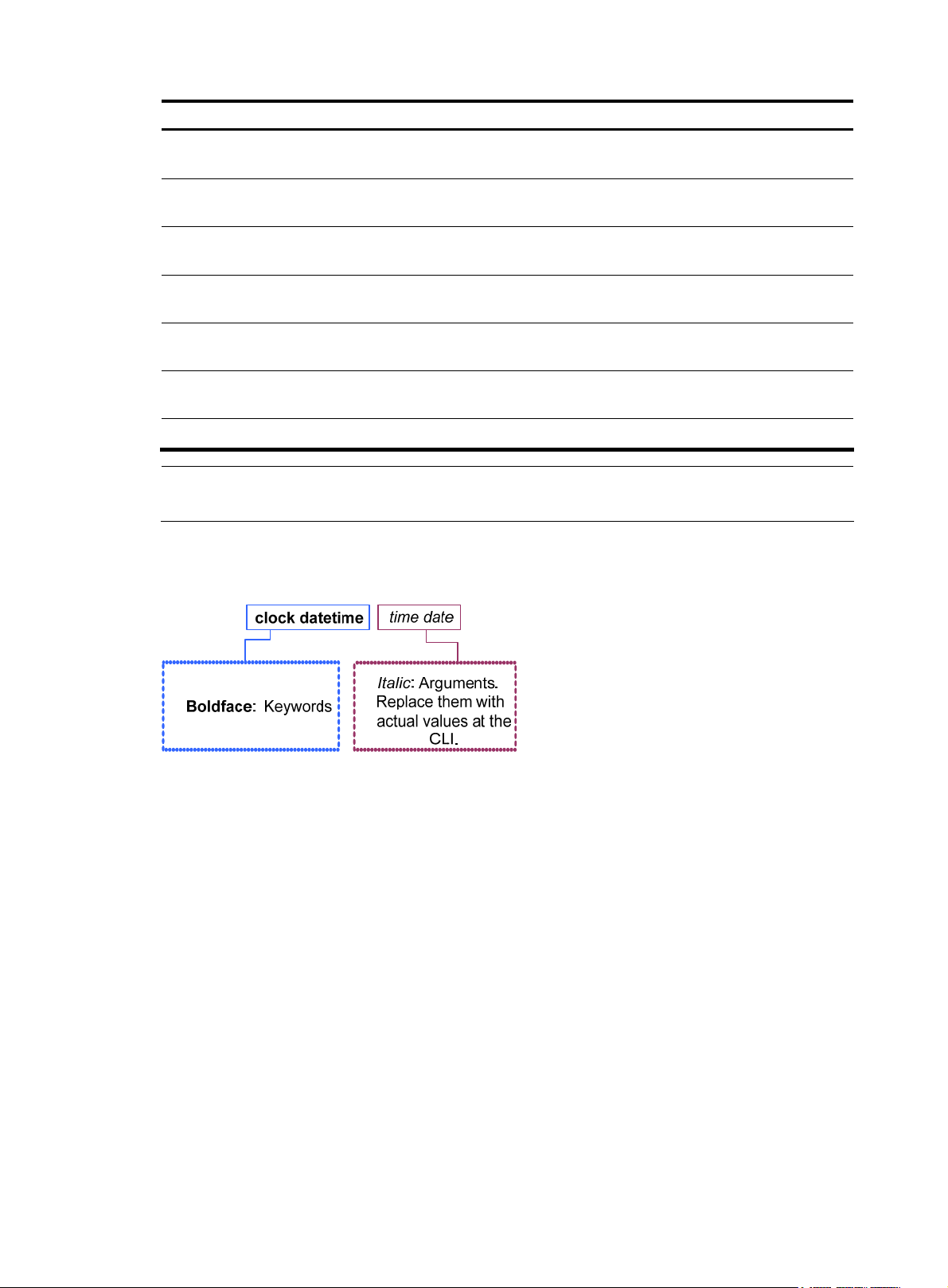
Figure 2 shows how to read the clock datetime time date command by using Table 1 as a reference.
Figure 2 Read command line parameters
Following this example, you can type the following command line at the CLI of your device and press
Enter to set the device system time to 10 o’clock 30 minutes 20 seconds, February 23, 2010.
<sysname> clock datetime 10:30:20 2/23/2010
More complicated commands can be understood using Table 1 as a reference.
Undo form of a command
The undo form of a command restores the default, disables a function, or removes a configuration.
Almost all configuration commands have an undo form. For example, the info-center enable command
enables the information center, and the undo info-center enable command disables the information
center.
CLI view description
Commands are grouped into different classes by function. To use a command, you must enter the class
view of the command.
2
Page 10

CLI views adopt a hierarchical structure. See Figure 3.
• After logging in to the switch, you are in user view. The user view prompt is <device name>. In user
view, you can perform display, debugging, and file management operations, set the system time,
restart your device, and perform FTP and Telnet operations.
• You can enter system view from user view. In system view, you can configure parameters such as
daylight saving time, banners, and short-cut keys.
• From system view, you can enter different function views. For example, enter interface view to
configure interface parameters, create a VLAN and enter its view, enter user interface view to
configure login user attributes, create a local user and enter local user view to configure the
password and level of the local user.
NOTE:
Enter ? in any view to display all the commands that can be executed in this view.
Figure 3 Command line views
Entering system view
When you log in to the device, you automatically enter user view, where <Device name> is displayed.
You can perform limited operations in user view, for example, display operations, file operations, and
Telnet operations. To perform further configuration on the device, enter system view.
Follow the step below to enter system view:
To do… Use the command… Remarks
Enter system view system-view
Exiting the current view
The CLI is divided into different command views. Each view has a set of specific commands and defines
the effective scope of the commands. The commands available to you at any given time depend on the
view you are in.
……
Required
Available in user view
Follow the step below to exit the current view:
3
Page 11

To do… Use the command… Remarks
y
Return to the parent view from the
current view
NOTE:
• The quit command in user view stops the current connection between the terminal and the device.
• In public key code view, use the public-key-code end
view). In public key view, use the peer-public-key end command to return to system view.
Returning to user view
This feature allows you to return to user view from any other view, without using the quit command
repeatedly. You can also press Ctrl+Z to return to user view from the current view.
Follow the step below to exit to user view:
To do… Use the command… Remarks
Return to user view return
quit
Required
Available in any view.
command to return to the parent view (public ke
Required
Available in any view except user
view
Using the CLI online help
Type a question mark (?) to obtain online help. See the following examples.
1. Type ? in any view to display all commands available in this view as well as brief descriptions of
the commands. For example:
<sysname> ?
User view commands:
archive Specify archive settings
backup Backup next startup-configuration file to TFTP server
boot-loader Set boot loader
bootrom Update/read/backup/restore bootrom
cd Change current directory
…Omitted…
2. Type part of a command and a ? separated by a space.
If ? is at the keyword position, the CLI displays all possible keywords with a brief description for each
keyword. For example:
<sysname> terminal ?
debugging Send debug information to terminal
logging Send log information to terminal
monitor Send information output to current terminal
trapping Send trap information to terminal
If ? is at the argument position, the CLI displays a description about this argument. For example:
<sysname> system-view
[sysname] interface vlan-interface ?
4
Page 12

<1-4094> VLAN interface
[sysname] interface vlan-interface 1 ?
<cr>
[sysname] interface vlan-interface 1
The string <cr> indicates that the command is a complete command, and can be executed by pressing
Enter.
3. Type an incomplete character string followed by ?. The CLI displays all commands starting with the
typed character(s).
<sysname> b?
backup
boot-loader
bootrom
<sysname> display cl?
clipboard
clock
cluster
Typing commands
Editing command lines
Table 2 Editing functions
Key Function
Common keys
Backspace
Left arrow key or Ctrl+B The cursor moves one character space to the left.
Right arrow key or Ctrl+F The cursor moves one character space to the right.
Tab
If the edit buffer is not full, pressing a common key inserts the character at the
position of the cursor and moves the cursor to the right.
Deletes the character to the left of the cursor and moves the cursor back one
character.
If you press Tab after entering part of a keyword, the system automatically
completes the keyword:
• If there is a unique match, the system substitutes the complete keyword for
the incomplete one and displays it in the next line.
• If there is more than one match, you can press Tab repeatedly to cycle
through all the keywords starting with the character string that you typed.
• If there is no match, the system does not modify the incomplete keyword
and displays it again in the next line.
Typing incomplete keywords
You can input a command comprising incomplete keywords that uniquely identify the complete
command.
In user view, for example, commands starting with an s include startup saved-configuration and
system-view.
• To enter system view, type sy.
5
Page 13

• To set the configuration file for next startup, type st s.
You can also press Tab to have an incomplete keyword automatically completed.
Configuring command aliases
The command alias function allows you to replace the first keyword of a command with your preferred
keyword. For example, if you configure show as the replacement for the display keyword, then to execute
the display xx command, you can input the command alias show xx.
Note the following guidelines when configuring a command alias:
• You can define and use a command alias but the command is not restored in its alias format.
• When you define a command alias, the cmdkey and alias arguments must be in their complete
form.
• When you input an incomplete keyword that partially matches both a defined alias and the
keyword of a command, the alias takes precedence. To execute the command whose keyword
partially matches your input, input the complete keyword. When you input a character string that
partially matches multiple aliases, the system gives you prompts.
• If you press Tab after you input an alias keyword, the original format of the keyword is displayed.
• You can replace only the first keyword of a non-undo command instead of the complete command.
You can replace only the second keyword of undo commands.
Follow these steps to configure command aliases:
To do… Use the command… Remarks
Enter system view system-view —
Enable the command alias function command-alias enable
Configure a command alias
Configuring CLI hotkeys
Follow these steps to configure CLI hotkeys:
To do… Use the command… Remarks
Enter system view system-view —
Configure CLI hotkeys
command-alias mapping cmdkey
alias
hotkey { CTRL_G | CTRL_L |
CTRL_O | CTRL_T | CTRL_U }
command
Required
Disabled by default, which means
you cannot configure command
aliases.
Required
Not configured by default.
Optional
The Ctrl+G, Ctrl+L and Ctrl+O
hotkeys are specified at the CLI by
default.
Display hotkeys display hotkey
6
Available in any view. See Table 3
for hotkeys reserved by the system.
Page 14

NOTE:
By default, the Ctrl+G, Ctrl+L and Ctrl+O hotkeys are associated with pre-defined commands as defined
below, the Ctrl+T and Ctrl+U hotkeys are not.
• Ctrl+G corresponds to the display current-configuration command.
• Ctrl+L corresponds to the display ip routing-table command.
• Ctrl+O corresponds to the undo debugging all command.
Table 3 Hotkeys reserved by the system
Hotkey Function
Ctrl+A Moves the cursor to the beginning of the current line.
Ctrl+B Moves the cursor one character to the left.
Ctrl+C Stops performing a command.
Ctrl+D Deletes the character at the current cursor position.
Ctrl+E Moves the cursor to the end of the current line.
Ctrl+F Moves the cursor one character to the right.
Ctrl+H Deletes the character to the left of the cursor.
Ctrl+K Terminates an outgoing connection.
Ctrl+N Displays the next command in the history command buffer.
Ctrl+P Displays the previous command in the history command buffer.
Ctrl+R Redisplays the current line information.
Ctrl+V Pastes the content in the clipboard.
Ctrl+W
Ctrl+X Deletes all characters to the left of the cursor.
Ctrl+Y Deletes all characters to the right of the cursor.
Ctrl+Z Exits to user view.
Ctrl+] Terminates an incoming connection or a redirect connection.
Esc+B
Esc+D
Esc+F
Esc+N
Deletes all the characters in a continuous string to the left of the
cursor.
Moves the cursor to the leading character of the continuous string to
the left.
Deletes all the characters of the continuous string at the current
cursor position and to the right of the cursor.
Moves the cursor to the front of the next continuous string to the
right.
Moves the cursor down by one line (available before you press
Enter)
Esc+P Moves the cursor up by one line (available before you press Enter)
Esc+< Specifies the cursor as the beginning of the clipboard.
Esc+> Specifies the cursor as the ending of the clipboard.
7
Page 15

NOTE:
g
d
The hotkeys in Table 3 are defined by the switch. If the
that you use to interact with the switch, the hotkeys defined by the terminal software take effect.
same hotkeys are defined by the terminal software
Redisplaying input but not submitted commands
If your command input is interrupted by output system information, you can use this feature to redisplay
the commands input previously but not submitted.
Follow these steps to enable redisplaying of commands previously input but not submitted:
To do… Use the command… Remarks
Enter system view system-view —
Enable redisplaying of input but
not submitted commands
NOTE:
• If you have no input at the command line prompt and the system outputs system information such as
logs, the system will not display the command line prompt after the output.
• If the system outputs system information when you are typin
confirmation), the system does not redisplay the prompt information but a line break after the output and
then display what you have typed.
info-center synchronous
Required
Disabled by default
interactive information (not YES/NO for
• For more information about the info-center synchronous command, see the
Monitoring Configuration Guide
.
Checking command-line errors
If a command contains syntax errors, the CLI reports error information.
Table 4 Common command line errors
Error information Cause
% Unrecognized command found at '^' position. The command was not found.
% Incomplete command found at '^' position. Incomplete command
% Ambiguous command found at '^' position. Ambiguous command
Too many parameters Too many parameters
% Wrong parameter found at '^' position. Wrong parameters
Using command history
Network Management an
The CLI automatically saves the commands recently used in the history command buffer. You can access
these commands and execute them again.
8
Page 16

Accessing history commands
Follow a step below to access history commands:
To do… Use the key/command… Result
Display history commands display history-command
Display the previous history
command
Display the next history
command
Up arrow key or Ctrl+P
Down arrow key or Ctrl+N Displays the next history command, if any
Displays valid history commands you
used
Displays the previous history command, if
any
NOTE:
You can use arrow keys to access history commands in Windows 200X and XP Terminal or Telnet.
However, the up and down arrow keys are invalid in Windows 9X HyperTerminal, because they are
defined differently. You can use Ctrl+P or Ctrl+N instead.
• The commands saved in the history command buffer are in the same format in which you typed the
commands. If you type an incomplete command, the command saved in the history command
buffer is also incomplete.
• If you execute the same command repeatedly, the switch saves only the earliest record. However, if
you execute the same command in different formats, the system saves them as different commands.
For example, if you execute the display cu command repeatedly, the system saves only one
command in the history command buffer. If you execute the command in the format of display cu
and display current-configuration respectively, the system saves them as two separate commands.
• By default, the CLI can save up to 10 commands for each user. To set the capacity of the history
command buffer for the current user interface, use the history-command max-size command. (For
more information about the history-command max-size command, see the chapter “Logging in to
the switch commands.”
Configuring the history buffer size
Follow these steps to configure the history buffer size:
To do… Use the command… Remarks
Enter system view system-view —
user-interface { first-num1
Enter user interface view
Set the maximum number of
commands that can be saved in the
history buffer
NOTE:
For more information about the user-interface and history-command max-size commands, see the
chapter “Logging in to the switch commands.”
[ last-num1 ] | { aux | vty }
first-num2 [ last-num2 ] }
history-command max-size
size-value
9
—
Optional
By default, the history buffer can
save up to 10 commands.
Page 17

Controlling the CLI display
Multi-screen display
Controlling multi-screen display
If the output information spans multiple screens, each screen pauses after it is displayed. Perform one of
the following operations to proceed.
Action Function
Press Space Displays the next screen.
Press Enter Displays the next line.
Press Ctrl+C Stops the display and the command execution.
Press <PageUp> Displays the previous page.
Press <PageDown> Displays the next page.
By defau lt, each screen displays up to 24 line s. To chang e the maximum number of lines d ispl ayed on the
next screen, use the screen-length command. For more information about the screen-length command,
see the chapter “Logging in to the switch commands.”
Disabling multi-screen display
You can use the following command to disable the multi-screen display function. All of the output
information will be displayed at one time and the screen will refresh continuously until the last screen is
displayed.
To do… Use the command… Remarks
Disable the multi-screen display
function
screen-length disable
Filtering output information
Introduction
Required
By default, a login user uses the
settings of the screen-length
command. The default settings of the
screen-length command are:
multiple-screen display is enabled
and up to 24 lines are displayed on
the next screen.
This command is executed in user
view, and takes effect for the current
user only. When the user re-logs into
the switch, the default configuration
is restored.
You can use regular expressions in display commands to filter output information.
The following methods are available for filtering output information:
• Input the begin, exclude, or include keyword plus a regular expression in the display command to
filter the output information.
10
Page 18

• When the system displays the output information in multiple screens, use /, - or + plus a regular
expression to filter subsequent output information. / equals the keyword begin, - equals the
keyword exclude, and + equals the keyword include.
The following definitions apply to the begin, exclude, and include keywords:
• begin: Displays the first line that matches the specified regular expression and all lines that follow.
• exclude: Displays all lines that do not match the specified regular expression.
• include: Displays all lines that match the specified regular expression.
A regular expression is a case-sensitive string of 1 to 256 characters. It supports the following special
characters.
Character Meaning Remarks
^string
string$
.
*
+
|
_
Starting sign. string appears only at
the beginning of a line.
Ending sign. string appears only at
the end of a line.
Matches any single character, such
as a single character, a special
character, and a blank.
Matches the preceding character or
character group zero or multiple
times.
Matches the preceding character or
character group one or multiple
times
Matches the preceding or
succeeding character string
If it i s at th e begi nning o r the end of a
regular expression, it equals ^ or $.
In other cases, it equals comma,
space, round bracket, or curly
bracket.
For example, regular expression “^user” only
matches a string beginning with “user”, not
“Auser”.
For example, regular expression "user$” only
matches a string ending with “user”, not “userA”.
For example, “.s” matches “as” and “bs”.
For example, “zo*” matches “z” and “zoo”;
“(zo)*” matches “zo” and “zozo”.
For example, “zo+” matches “zo” and “zoo”, but
not “z”.
For example, “def|int” only matches a character
string containing “def” or “int”.
For example, “a_b” matches “a b” or “a(b”; “_ab”
only matches a line starting with “ab”; “ab_” only
matches a line ending with “ab”.
Connects two values (the smaller one
-
[ ]
( )
before it and the bigger one after it)
to indicate a range together with [ ].
Matches a single character
contained within the brackets.
A character group. It is usually used
with “+” or “*”.
11
For example, “1-9” means 1 to 9 (inclusive); “a-h”
means a to h (inclusive).
For example, [16A] matches a string containing
any character among 1, 6, and A; [1-36A] matches
a string containing any character among 1, 2, 3, 6,
and A (- is a hyphen).
“]” can be matched as a common character only
when it is put at the beginning of characters within
the brackets, for example [ ]string]. There is no such
limit on “[”.
For example, (123A) means a character group
“123A”; “408(12)+” matches 40812 or
408121212. But it does not match 408.
Page 19

Character Meaning Remarks
Repeats the character string
specified by the index. A character
For example, (string)\1 repeats string, and a
matching string must contain stringstring.
(string1)(string2)\2 repeats string2, and a
matching string must contain string1string2string2.
(string1)(string2)\1\2 repeats string1 and string2
respectively, and a matching string must contain
string1string2string1string2.
For example, [^16A] means to match a string
containing any character except 1, 6 or A, and the
matching string can also contain 1, 6 or A, but
cannot contain these three characters only. For
example, [^16A] matches “abc” and “m16”, but
not 1, 16, or 16A.
\index
[^]
string refers to the string within ()
before \. index refers to the
sequence number (starting from 1
from left to right) of the character
group before \. If only one character
group appears before \, index can
only be 1; if n character groups
appear before index, index can be
any integer from 1 to n.
Matches a single character not
contained within the brackets.
\<string
string\>
\bcharacter2
\Bcharacter
character1\w
\W Equals \b.
\
Matches a character string starting
with string.
Matches a character string ending
with string.
Matches character1character2.
character1 can be any character
except number, letter or underline,
and \b equals [^A-Za-z0-9_].
Matches a string containing
character, and no space is allowed
before character.
Matches character1character2.
character2 must be a number, letter,
or underline, and \w equals
[^A-Za-z0-9_].
Escape character. If a special
character listed in this table follows
\, the specific meaning of the
character is removed.
For example, “\<do” matches word “domain” and
string “doa”.
For example, “do\>” matches word “undo” and
string “abcdo”.
For example, “\ba” matches “-a” with “-“ being
character1, and “a” being character2, but it does
not match “2a” or “ba”.
For example, “\Bt” matches “t” in “install”, but not
“t” in “big top”.
For example, “v\w” matches “vlan”, with “v” being
character1, and “l” being character2. v\w also
matches “service”, with “i” being character2.
For example, “\Wa” matches “-a”, with “-” being
character1, and “a” being character2, but does not
match “2a” or “ba”.
For example, “\\” matches a string containing “\”,
“\^” matches a string containing “^”, and “\\b”
matches a string containing “\b”.
Example of filtering output information
1. Example of using the begin keyword
# Display the configuration from the line containing “user-interface” to the last line in the current
configuration (the output information depends on the current configuration).
<Sysname> display current-configuration | begin user-interface
user-interface aux 0
user-interface vty 0 15
authentication-mode none
12
Page 20

user privilege level 3
#
return
2. Example of using the exclude keyword
# Display the non-direct routes in the routing table (the output depends on the current configuration).
<Sysname> display ip routing-table | exclude Direct
Routing Tables: Public
Destination/Mask Proto Pre Cost NextHop Interface
1.1.1.0/24 Static 60 0 192.168.0.0 Vlan1
3. Example of using the include keyword
# Display the route entries that contain Vlan in the routing table (the output depends on the current
configuration).
<Sysname> display ip routing-table | include Vlan
Routing Tables: Public
Destination/Mask Proto Pre Cost NextHop Interface
192.168.1.0/24 Direct 0 0 192.168.1.42 Vlan999
Configuring user privilege and command levels
Introduction
To avoid unauthorized access, the switch defines user privilege levels and command levels. User privilege
levels correspond to command levels. When a user at a specific privilege level logs in, the user can only
use commands at that level or lower levels.
All the commands are categorized into four levels: visit, monitor, system, and manage, and are identified
from low to high, respectively by 0 through 3. Table 5 describes the command levels.
Table 5 Default command levels
Level Privilege Description
Involves commands for network diagnosis and accessing an external device.
0 Visit
1 Monitor
Command configuration at this level cannot survive a device restart. Upon device
restart, the commands at this level will be restored to the default settings.
Commands at this level include ping, tracert, telnet and ssh2.
Involves commands for system maintenance and service fault diagnosis.
Commands at this level are not allowed to be saved after being configured. After
the switch is restarted, the commands at this level will be restored to the default
settings.
Commands at this level include debugging, terminal, refresh, reset, and send.
Involves service configuration commands, such as routing configuration
2 System
commands and commands for configuring services at different network levels.
By default, commands at this level include all configuration commands except for
those at the manage level.
13
Page 21

Level Privilege Description
Involves commands that influence the basic operation of the system and
commands for configuring system support modules.
3 Manage
By default, commands at this level involve the configuration commands of file
system, FTP, TFTP, Xmodem download, user management, level setting, and
parameter settings within a system (which are not defined by any protocols or
RFCs).
Configuring a user privilege level
A user privilege level can be configured by using AAA authentication parameters or under a user
interface.
Configure user privilege level by using AAA authentication parameters
If the user interface authentication mode is scheme, the user privilege level of users logging into the user
interface is specified in AAA authentication configuration.
Follow these steps to configure the user privilege level by using AAA authentication parameters:
To do… Use the command… Remarks
Enter system view system-view —
user-interface { first-num1
Enter user interface view
[ last-num1 ] | { aux | vty }
first-num2 [ last-num2 ] }
—
Specify the scheme authentication
mode
Return to system view quit —
Configure the authentication mode
for SSH users as password
authentication-mode scheme
For more information about SSH,
see the Security Configuration
Guide.
• Use the local-user command to
create a local user and enter
local user view.
• Use the level keyword in the
authorization-attribute
command to configure the user
privilege level.
Configure the user privilege level
on the authentication server
Configure the
user privilege
level by using
AAA
authentication
parameters
Using local
authentication
Using remote
authentication
(RADIUS,
HWTACACS
authentications)
Required
By default, the authentication
mode for VTY users is password,
and no authentication is needed
for AUX login users.
Required if users use SSH to log in,
and username and password are
needed at authentication
Use either approach
• For local authentication, if you
do not configure the user
privilege level, the user
privilege level is 0.
• For remote authentication, if
you do not configure the user
privilege level, the user
privilege level depends on the
default configuration of the
authentication server.
Example of configuring a user privilege level by using AAA authentication parameters
# You are required to authenticate the users that Telnet to the switch through VTY 1, verify their username
and password, and specify the user privilege level as 3.
14
Page 22

<Sysname> system-view
[Sysname] user-interface vty 1
[Sysname-ui-vty1] authentication-mode scheme
[Sysname-ui-vty1] quit
[Sysname] local-user test
[Sysname-luser-test] password cipher 12345678
[Sysname-luser-test] service-type telnet
When users telnet to the switch through V TY 1, they need to input username test and password 123 4 567 8.
After passing authentication, the users can only use level 0 commands. If the users want to use
commands level 0, 1, 2 and 3 commands, the following configuration is required:
[Sysname-luser-test] authorization-attribute level 3
Configure the user privilege level under a user interface
• If the user interface authentication mode is scheme, and SSH publickey authentication type (only a
username is needed for this authentication type) is adopted, the user privilege level of users logging
into the user interface is the user interface level.
• If the user interface authentication mode is none or password, the user privilege level of users
logging into the user interface is the user interface level.
Follow these steps to configure the user privilege level under a user interface (SSH publickey
authentication type):
To do… Use the command… Remarks
Required if the SSH login mode is
adopted, and only username is
Configure the authentication type
for SSH users as publickey
Enter system view system-view —
Enter user interface view
Configure the authentication mode
for any user that uses the current
user interface to log in to the switch
Configure the privilege level for
users that log in through the current
user interface
For more information about SSH,
see the Security Configuration
Guide.
user-interface { first-num1
[ last-num1 ] | vty first-num2
[ last-num2 ] }
authentication-mode scheme
user privilege level level
needed during authentication.
After the configuration, the
authentication mode of the
corresponding user interface must
be set to scheme.
—
Required
By default, the authentication
mode for VTY users is password,
and no authentication is needed
for AUX users.
Optional
By default, the user privilege level
for users logged in through the
AUX user interface is 3, and that
for users logged in through the VTY
interfaces is 0.
Follow these steps to configure the user privilege level under a user interface (none or password
authentication mode):
15
Page 23

To do… Use the command… Remarks
Enter system view system-view —
user-interface { first-num1
Enter user interface view
Configure the authentication mode
for any user that uses the current
user interface to log in to the switch
Configure the privilege level of
users logged in through the current
user interface
[ last-num1 ] | { aux | vty }
first-num2 [ last-num2 ] }
authentication-mode { none |
password }
user privilege level level
Example of configuring a user privilege level under a user interface
# Authenticate users logged in to the switch through Telnet, verify their password, and specify their user
privilege level as 2.
<Sysname> system-view
[Sysname] user-interface vty 0 15
[Sysname-ui-vty0-15] authentication-mode password
[Sysname-ui-vty0-15] set authentication password cipher 123
[Sysname-ui-vty0-15] user privilege level 2
—
Optional
By default, the authentication
mode for VTY user interfaces is
password, and no authentication is
needed for AUX login users.
Optional
By default, the user privilege level
for users logged in through the
AUX user interface is 3, and that
for users logged in through the VTY
interfaces is 0.
By default, Telnet users can use level 0 commands after passing authentication. After the configuration
above is completed, when users log in to the switch through Telnet, t hey need to input password 12 3 , and
then they can use level 0, 1, and 2 commands.
NOTE:
• For more information about user interfaces, see the chapter “Logging in to the switch configuration.”
more information about the user-interface, authentication-mode, and user privilege level commands,
see the chapter “Logging in to the switch commands.”
• For more information about AAA authentication, see the
information about the local-user and authorization-attribute commands, see the
Reference
.
• For more information about SSH, see the
Switching user privilege level
Introduction
Users can switch to a different user privilege level temporarily without logging out and terminating the
current connection. After the privilege level switch, users can continue to configure the switch without the
need to logging back in, but the commands that they can execute have changed. For example, if the
current user privilege level is 3, the user can configure system parameters. After switching to user
privilege level 0, the user can only execute simple commands, like ping and tracert, and only a few
Security Configuration Guide
Security Configuration Guide
For
. For more
Security Command
.
16
Page 24

display commands. The switching operation is effective for the current login. After the user logs back in,
the user privilege restores to the original level.
• To avoid problems, HP recommends that administrators log in to the switch by using a lower
privilege level and view switch operating parameters. To maintain the switch, administrators can
temporarily switch to a higher level.
• If the administrators need to leave or need to ask someone else to temporarily manage the switch,
they can switch to a lower privilege level to restrict the operation by others.
Setting the authentication mode for user privilege level switch
• A user can switch to a privilege level equal to or lower than the current one unconditionally and is
not required to input a password (if any).
• For security, a user i s required to input the password (if any) to switch to a higher privilege level. The
authentication falls into one of the following four categories:
Authentication
mode
local
scheme
local scheme
Meaning Description
The switch authenticates a user by using the privilege level switch
Local password
authentication
Remote AAA
authentication
through
HWTACACS or
RADIUS
password input by the user.
When this mode is applied, you need to set the password for
privilege level switch with the super password command.
The switch sends the username and password for privilege level
switch to the HWTACACS or RADIUS server for remote
authentication.
When this mode is applied, you need to perform the following
configurations:
• Configure HWTACACS or RADIUS scheme and reference the
created scheme in the ISP domain. For more information, see the
Security Configuration Guide.
• Create the corresponding user and configure password on the
HWTACACS or RADIUS server.
Performs the local
password
authentication first
and then the
remote AAA
authentication
The switch authenticates a user by using the local password first. If
no local password is set, the privilege level is switched directly for
the users logged in from the AUX port, and remote AAA
authentication is performed on the users logged in from VTY user
interfaces.
Performs remote
AAA authentication is performed first, and if the remote
HWTACACS or RADIUS server does not respond or AAA
configuration on the switch is invalid, the local password
authentication is performed.
scheme local
AAA
authentication first
and then the local
password
authentication
Follow these steps to set the authentication mode for user privilege level switch:
To do… Use the command… Remarks
Enter system view system-view —
Set the authentication mode for
user privilege level switch
super authentication-mode { local
| scheme } *
17
Optional
local by default.
Page 25

To do… Use the command… Remarks
g
Required if the authentication
Configure the password for user
privilege level switch
CAUTION:
super password [ level user-level ]
{ simple | cipher } password
mode is set to local.
By default, no privilege level switch
password is configured.
• If no user privilege level is specified when you configure the password for switching the user privilege
level with the super password command, the user privilege level defaults to 3.
• Specifying the simple keyword saves the password in plain text, which is less secure than specifyin
cipher keyword, which saves the password in cipher text.
• If the user logs in from the AUX user interface (the console port), the user can switch the privilege
to a higher level even if the authentication mode is local and no password
is configured.
Switching the user privilege level
Follow the step to switch the user privilege level:
To do… Use the command… Remarks
Switch the user privilege level super [ level ]
When you switch the user privilege level, the information you need to provide varies with combinations
of the user interface authentication mode and the super authentication mode.
Table 6 Information input for user privilege level switch
the
level
for user privilege level switch
Required
When logging in to the switch, a
user has a user privilege level,
which depends on user interface or
authentication user level.
Available in user view.
User interface
authentication
mode
none/password
User privilege level
switch
authentication
mode
local
local scheme
scheme
scheme local
Information input for the
first authentication mode
Local user privilege level
switch password (configured
on the switch)
Local user privilege level
switch password
Username and password for
privilege level switch
Username and password for
privilege level switch
18
Information input after the
authentication mode changes
—
Username and password for
privilege level switch (configured
on the AAA server)
—
Local user privilege level switch
password
Page 26

User interface
g
authentication
mode
User privilege level
switch
authentication
mode
Information input for the
first authentication mode
Information input after the
authentication mode changes
Local user privilege level
switch password
Local user privilege level
switch password
Password for privilege level
switch (configured on the
AAA server). The system uses
the username used for
logging in as the privilege
level switch username.
Password for privilege level
switch (configured on the
AAA server). The system uses
the username used for
logging in as the privilege
level switch username.
—
Password for privilege level
switch (configured on the AAA
server). The system uses the
username used for logging in as
the privilege level switch
username.
—
Local user privilege level switch
password
scheme
CAUTION:
local
local scheme
scheme
scheme local
• When the authentication mode is set to local, configure the local password before switching to a hi
user privilege level.
her
• When the authentication mode is set to scheme, configure AAA related parameters before switching to
a higher user privilege level.
• The privilege level switch fails after three consecutive unsuccessful password attempts.
• For more information about user interface authentication, see the chapter “Logging in to the switch
configuration.”
Modifying the level of a command
All the commands in a view default to different levels. The administrator can change the default level of
a command to a different level as needed.
Follow these steps to modify the command level:
To do… Use the command… Remarks
Enter system view system-view —
Configure the command level in a
specified view
command-privilege level level view
view command
Required
See Table 5 for the default settings.
19
Page 27

CAUTION:
HP recommends that you use the default command level
of professional staff. An improper change of the command level may bring inconvenience to your
maintenance and operation, or even potential security problems.
or modify the command level under the guidance
Saving the current configuration
On the device, you can input the save command in any view to save all of the submitted and executed
commands into the configuration file. Commands saved in the configuration file can survive a reboot.
The save command does not take effect on one-time commands, such as display commands, which
display specified information, and the reset commands, which clear specified information. One-time
commands that are executed are never saved.
Displaying and maintaining CLI
To do… Use the command… Remarks
Display defined command aliases
and the corresponding commands
Display the clipboard information
display command-alias [ | { begin
| exclude | include }
regular-expression ]
display clipboard [ | { begin |
exclude | include }
regular-expression ]
Available in any view
Available in any view
20
Page 28

Login methods
Login methods
You can log in to the switch by using the following methods.
Table 7 Login methods
Login method Default state
CLI login
Logging in
through the
console port
By default, you can log in to a device through the console port, the
authentication mode is None (no username or password required),
and the user privilege level is 3.
By default, you cannot log in to a device through Telnet. To do so, log
in to the device through the console port, and complete the following
configuration:
• Enable the Telnet function.
Logging in
through
• Configure the IP address of the VLAN interface, and make sure that
your device and the Telnet client can reach each other (by default,
the device does not have an IP address.).
• Configure the authentication mode of VTY login users (password
by default).
• Configure the user privilege level of VTY login users (0 by default).
By default, you cannot log in to a device through SSH. To do so, log
in to the device through the console port, and complete the following
configuration:
• Enable the SSH function and configure SSH attributes.
Logging in
through SSH
• Configure the IP address of the VLAN interface, and make sure that
your device and the SSH client can reach each other (by default,
your device does not have an IP address.).
• Configure the authentication mode of VTY login users as scheme
(password by default).
• Configure the user privilege level of VTY login users (0 by default).
Logging in
through modems
By default, you can log in to a device through modems. The default
user privilege level of modem login users is 3.
By default, you cannot log in to a device through web. To do so, log
in to the device through the console port, and complete the following
configuration:
• Configure the IP address of the VLAN interface (by default, your
device does not have an IP address.).
Web login
• Configure a username and password for web login (not configured
by default).
• Configure the user privilege level for web login (not configured by
default).
• Configure the Telnet service type for web login (not configured by
default).
21
Page 29

Login method Default state
By default, you cannot log in to a device through a network
management system (NMS). To do so, log in to the device through the
console port, and complete the following configuration:
NMS login
• Configure the IP address of the VLAN interface, and make sure the
device and the NMS can reach each other (by default, your device
does not have an IP address.).
• Configure SNMP basic parameters.
User interface overview
User interface, also called “line”, allows you to manage and monitor sessions between the terminal and
device when you log in to the device through the console port directly, or through Telnet or SSH.
One user interface corresponds to one user interface view where you can configure a set of parameters,
such as whether to authenticate users at login, whether to redirect the requests to another device, and the
user privilege level after login. When the user logs in through a user interface, the parameters set for the
user interface apply.
The system supports the following CLI configuration methods:
• Local configuration via the console port
• Local/Remote configuration through Telnet or SSH
The methods correspond to the following user interfaces.
• AUX user interface: Used to manage and monitor user that log in via the Console port. The type of
the Console port is EIA/TIA-232 DCE.
• VTY (virtual type terminal) user interface: Used to manage and monitor users that log in via VTY. A
VTY port used for Telnet or SSH access.
Users and user interfaces
Only one user can use a user interface at a time. The configuration made in a user interface view applies
to any login user. For example, if user A uses the console port to log in, the configuration in the AUX user
interface view applies to user A; i f user A logs in through VT Y 1, the configuration in VTY 1 user interface
view applies to user A.
A device can be equipped with one AUX user interface and 16 VTY user interfaces. These user interfaces
are not associated with specific users. When a user initiates a connection request, the system
automatically assigns the idle user interface with the smallest number to the user based on the login
method. During the login, the configuration in the user interface view takes effect. The user interface
varies depending on the login method and the login time.
Numbering user interfaces
User interfaces can be numbered by using absolute numbering or relative numbering.
Absolute numbering
Absolute numbering identifies a user interface or a group of different types of user interfaces. The
specified user interfaces are numbered from number 0 with a step of 1 and in the sequence of AUX, and
22
Page 30

VTY user interfaces. You can use the display user-interface command without any parameters to view
supported user interfaces and their absolute numbers.
Relative numbering
Relative numbering allows you to specify a user interface or a group of user interfaces of a specific type.
The number format is “user interface type + number”. The following rules of relative numbering apply:
• AUX user interfaces are numbered from 0 in the ascending order, with a step of 1.
• VTY user interfaces are numbered from 0 in the ascending order, with a step of 1.
23
Page 31

CLI login
Overview
The CLI enables you to interact with a device by typing text commands. At the CLI, you can instruct your
device to perform a given task by typing a text command and then pressing Enter to submit it to your
device. Compared with a GUI, where you can use a mouse to perform configuration, the CLI allows you
to input more information in one command line.
You can log in to the device at the CLI through the console port, Telnet, SSH, or modem.
• By default, you can log in to a device through the console port without any authentication, which
introduces security problems.
• By default, you cannot log in to a device through Telnet, SSH, so you cannot remotely manage and
maintain the device.
Therefore, you need to perform configurations to increase device security and manageability.
Logging in through the console port
Introduction
Logging in through the console port is the most common login method, and is also the first step to
configure other login methods.
After logging in to the device through the console port, you can configure other login methods. By default,
you can log in to a device only through its console port.
This section includes:
• Configuration requirements
• Login procedure
• Console login authentication modes
• Configuring none authentication for console login
• Configuring password authentication for console login
• Configuring scheme authentication for console login
• Configuring common settings for console login (optional)
Configuration requirements
The following table shows the configuration requirements for console port login.
Object Requirements
Device No configuration requirement
Run the hyper terminal program.
Terminal
Configure the hyper terminal attributes.
24
Page 32

g
The port properties of the hyper terminal must be the same as the default settings of the console port
shown in the following table.
Setting Default
Bits per second 9,600 bps
Flow control None
Parity None
Stop bits 1
Data bits 8
Login procedure
Step1 Use the console cable shipped with the device to connect the PC and the device. Plug the DB-9 connector
of the console cable into the serial port of the PC, and plug the RJ-45 connector into the console port of
your device.
Figure 4 Connect the device and PC through a console cable
WARNING!
Identify interfaces to avoid connection errors.
NOTE:
The serial port of a PC does not support hot-swap, so do not plug or unplug the console cable into or from
the PC when your device is powered on. To connect the PC to the device, first plug the DB-9 connector of
the console cable into the PC, and then plug the RJ-45 connector of the console cable into your device. To
disconnect the PC from the device, first unplug the RJ-45 connector and then the DB-9 connector.
Step2 Launch a terminal emulation program (such as HyperTerminal in Windows XP/Windows 2000). The
following takes Windows XP’s HyperTerminal as an example. Select a serial port to be connected to the
device, and set terminal parameters as follows: set Bits per second to 9600, Data bits to 8, Parity to
None, Stop bits to 1, and Flow control to None, as shown in Figure 5 through Figure 7.
NOTE:
On Windows 2003 Server operatin
system, you need to add the HyperTerminal program first, and then
log in to and manage the device as described in this document. On Windows 2008 Server, Windows 7,
Windows Vista, or some other operating system, you need to obtain a third party terminal control
program first, and follow the user guide or online help of that program to log in to the device.
25
Page 33

Figure 5 Connection description
Figure 6 Specify the serial port used to establish the connection
26
Page 34

Figure 7 Set the properties of the serial port
Step3 Turn on the device. You are prompted to press Enter if the device successfully completes the power-on self
test (POST). A prompt such as <HP> appears after you press Enter, as shown in Figure 8.
Figure 8 Configuration page
Step4 Execute commands to configure the device or check the running status of the device. To get help, type ?.
Console login authentication modes
The following authentication modes are available for console port login: none, password, and scheme.
27
Page 35

• none—Requires no username and password at the next login through the console port. This mode
is insecure.
• password—Requires password authentication at the next login through the console port. Keep your
password.
• scheme—Requires username and password authentication at the next login through the console
port. Authentication falls into local authentication and remote authentication. To use local
authentication, configure a local user and related parameters. To use remote authentication,
configure the username and password on the remote authentication server. For more information
about authentication modes and parameters, see the Security Configuration Guide.
The following table lists console port login configurations for different authentication modes:
Authenticat
ion mode
None Configure not to authenticate users
Password
Scheme
Configuration Remarks
Configure to authenticate users by using the local password
Set the local password
Configure the authentication scheme
Remote AAA
authentication
Select an
authentication
scheme
Configure a
RADIUS/HWTACAC
S scheme
Configure the AAA
scheme used by the
domain
Configure the
username and
password on the
AAA server
For more information, see
“Configuring none
authentication for console
login.”
For more information, see
“Configuring password
authentication for console
login.”
For more information, see
“Configuring scheme
authentication for console
login.”
Configure the
authentication
Local
authentication
username and
password
Configure the AAA
scheme used by the
domain as local
NOTE:
A newly configured authentication mode does not take effect unless you exit and enter the CLI again.
Configuring none authentication for console login
Configuration prerequisites
You have logged in to the device.
28
Page 36

By default, you can log in to the device through the console port without authentication and have user
privilege level 3 after login. For information about logging in to the device with the default configuration,
see “Configuration requirements.”
Configuration procedure
Follow these steps to configure none authentication for console login:
To do… Use the command… Remarks
Enter system view system-view —
Enter AUX user interface view
Specify the none authentication
mode
Configure common settings for
AUX user interface view
user-interface aux first-number
[ last-number ]
authentication-mode none
—
—
Required
By default, you can log in to the
device through the console port
without authentication, and have
user privilege level 3 after login.
Optional
See “Configuring common settings
for console login (optional).”
After the configuration, the next time you log in to the device through the console port, you are prompted
to press Enter. A prompt such as <HP> appears after you press Enter, as shown in Figure 9.
Figure 9 Configuration page
Configuring password authentication for console login
Configuration prerequisites
You have logged in to the device.
29
Page 37

By default, you can log in to the device through the console port without authentication and have user
privilege level 3 after login. For information about logging in to the device with the default configuration,
see “Configuration requirements.”
Configuration procedure
Follow these steps to configure password authentication for console login:
To do… Use the command… Remarks
Enter system view system-view —
Enter AUX user interface view
Configure the authentication mode
as local password authentication
Set the local password
Configure common settings for
AUX user interface view
user-interface aux first-number
[ last-number ]
authentication-mode password
set authentication password
{ cipher | simple } password
—
—
Required
By default, you can log in to the
device through the console port
without authentication and have
user privilege level 3 after login.
Required
By default, no local password is
set.
Optional
See “Configuring common settings
for console login (optional).”
When you log in to the device through the console port after configuration, you are prompted to enter a
login password. A prompt such as <HP> appears after you input the password and press Enter, as shown
in Figure 10.
Figure 10 Configuration page
30
Page 38

Configuring scheme authentication for console login
Configuration prerequisites
You have logged in to the device.
By default, you can log in to the device through the console port without authentication and have user
privilege level 3 after login. For information about logging in to the device with the default configuration,
see “Configuration requirements.”
Configuration procedure
Follow these steps to configure scheme authentication for console login:
To do… Use the command… Remarks
Enter system view system-view —
Enter AUX user interface view
Specify the scheme
authentication mode
Enable command authorization command authorization
user-interface aux first-number
[ last-number ]
authentication-mode scheme
—
Required
Whether local, RADIUS, or
HWTACACS authentication is
adopted depends on the configured
AAA scheme.
By default, users that log in through
the console port are not
authenticated.
Optional
• By default, command
authorization is not enabled.
• By default, the command level
depends on the user privilege
level. A user is authorized a
command level not higher than
the user privilege level. With
command authorization
enabled, the command level for
a login user is determined by
both the user privilege level and
AAA authorization. If a user
executes a command of the
corresponding command level,
the authorization server checks
whether the command is
authorized. If yes, the command
can be executed.
• Before enabling command
authorization, configure the AAA
authorization server. After you
enable command authorization,
only commands authorized by
the AAA authorization server can
be executed.
31
Page 39

To do… Use the command… Remarks
Optional
• By default, command accounting
is disabled. The accounting
server does not record the
commands executed by users.
• Command accounting allows the
HWTACACS server to record all
the commands executed by
users, regardless of command
execution results. This helps
control and monitor user
operations on the device. If
Enable command accounting command accounting
command accounting is enabled
and command authorization is
not enabled, every executed
command is recorded on the
HWTACACS server. If both
command accounting and
command authorization are
enabled, only the authorized and
executed commands are
recorded on the HWTACACS
server.
• Configure the AAA accounting
server before enabling command
accounting.
Return to system view quit —
Enter the ISP
domain view
Apply the
specified AAA
scheme to the
domain
Configure
the
authentica
tion mode
Exit to system view quit
Create a local user and enter
local user view
Set the authentication password
for the local user
domain domain-name
authentication default
{ hwtacacs-scheme
hwtacacs-scheme-name [ local ] |
local | none | radius-scheme
radius-scheme-name [ local ] }
local-user user-name
password { cipher | simple }
password
Optional
By default, the AAA scheme is local.
If you specify the local AAA scheme,
you need to perform local user
configuration. If you specify an
existing scheme by providing the
radius-scheme-name argument,
perform the following configuration
as well:
• For RADIUS and HWTACACS
• Configure the username and
Required
By default, no local user exists.
Required
configuration, see the Security
Configuration Guide.
password on the AAA server.
(For more information about
AAA, see the Security
Configuration Guide.)
Specify the command level of
the local user
authorization-attribute level level
32
Optional
By default, the command level is 0.
Page 40

To do… Use the command… Remarks
Specify the service type for the
local user
Configure common settings for
AUX user interface view
service-type terminal
—
Required
By default, no service type is
specified.
Optional
See “Configuring common settings
for console login (optional).”
After you enable command authorization, you need to perform the following configuration to make the
function take effect:
• Create a HWTACACS scheme, and specify the IP address of the authorization server and other
authorization parameters. For more information about AAA, see the Security Configuration Guide.
• Reference the created HWTACACS scheme in the ISP domain. For more information about AAA,
see the Security Configuration Guide.
After you enable command accounting, you need to perform the following configuration to make the
function take effect:
• Create a HWTACACS scheme, and specify the IP address of the accounting server and other
accounting parameters. For more information about AAA, see the Security Configuration Guide.
• Reference the created HWTACACS scheme in the ISP domain. For more information about AAA,
see the Security Configuration Guide.
When users adopt the scheme mode to log in to the device, the level of the commands that the users can
access depends on the user privilege level defined in the AAA scheme.
• When the AAA scheme is local, the user privilege level is defined by the authorization-attribute
level level command.
• When the AAA scheme is RADIUS or HWTACACS, the user privilege level is configured on the
RADIUS or HWTACACS server.
• For more information about AAA, RADIUS, and HWTACACS, see the Security Configuration
Guide.
When you log in to the device through the console port after the configuration, you are prompted to enter
a login username and password. A prompt such as <HP> appears after you input the password and
username and press Enter, as shown in
Figure 11.
33
Page 41

Figure 11 Configuration page
Configuring common settings for console login (optional)
Follow these steps to configure common settings for console port login
To do… Use the command… Remarks
Enter system view system-view —
Enable display of copyright
information
Enter AUX user interface view
Configure
AUX user
interface
view
properties
Configure the
baud rate
Configure the
parity check mode
Configure the stop
bits
copyright-info enable
user-interface aux first-number
[ last-number ]
speed speed-value
parity { even | none | odd }
stopbits { 1 | 1.5 | 2 }
Optional
Enabled by default.
—
Optional
By default, the transmission rate is
9600 bps.
Transmission rate is the number of
bits that the device transmits to the
terminal per second.
Optional
none by default.
Optional
By default, the stop bits of the
console port is 1.
Stop bits are the last bits transmitted
in data transmission to
unequivocally indicate the end of a
character. The more the bits are, the
slower the transmission is.
34
Page 42

To do… Use the command… Remarks
Optional
By default, the data bits of the
console port is 8.
Data bits is the number of bits
Configure the data
bits
databits { 5 | 6 | 7 | 8 }
representing one character. The
setting depends on the contexts to
be transmitted. For example, you
can set it to 7 if standard ASCII
characters are to be sent, and set it
to 8 if extended ASCII characters
are to be sent.
Define a shortcut
key for enabling a
terminal session
Define a shortcut
key for terminating
tasks
Configure the flow
control mode
Configure the type
of terminal display
activation-key character
escape-key { default | character }
flow-control { hardware | none |
software }
terminal type { ansi | vt100 }
Optional
By default, you can press Enter to
enable a terminal session.
Optional
By default, you can press Ctrl+C to
terminate a task.
Optional
By default, the value is none
Optional
By default, the terminal display type
is ANSI.
The device supports two types of
terminal display: ANSI and VT100.
HP recommends that you set the
display type of both the device and
the client to VT100. If the device and
the client use different display types
(for example, hyper terminal or
Telnet terminal) or both are set to
ANSI, when the total number of
characters of the edited command
line exceeds 80, an anomaly such
as cursor corruption or abnormal
display of the terminal display may
occur on the client.
Configure the user
privilege level for
login users
Set the maximum
number of lines on
the next screen.
Set the size of
history command
buffer
user privilege level level
screen-length screen-length
history-command max-size value
35
Optional
By default, the default command
level is 3 for the AUX user interface.
Optional
By default, the next screen displays
24 lines.
A value of 0 disables the function.
Optional
By default, the buffer saves 10
history commands at most.
Page 43

t
To do… Use the command… Remarks
CAUTION:
Set the idle-timeout
timer
idle-timeout minutes [ seconds ]
The common settings configured for console login take effect immediately. If you configure the common
settings after you log in through the console port, the current connection may be interrupted, so you mus
use another login method. After you configure common settings for console login, you need to modify the
settings on the terminal to make them consistent with those on the device.
Logging in through Telnet
Optional
The default idle-timeout is 10
minutes. The system automatically
terminates the user’s connection if
no information interaction occurs
between the device and the user
within the idle-timeout time.
Setting idle-timeout to 0 disables the
timer.
Introduction
The device supports Telnet. You can Telnet to the device to remotely manage and maintain it, as shown
in Figure 12.
Figure 12 Telnet login
The following table shows the configuration requirements of Telnet login.
Object Requirements
Telnet server
Telnet client
By default, the device is enabled with the Telnet server and client functions.
• On a device that serves as the Telnet client, you can log in to a Telnet server to perform operations
on the server.
Configure the IP address of the VLAN interface, and make sure the Telnet
server and client can reach each other.
Configure the authentication mode and other settings
Run the Telnet client program.
Obtain the IP address of the VLAN interface on the server
• On a device that serves as the Telnet server, you can configure the authentication mode and user
privilege level for Telnet users. By default, you cannot log in to the device through Telnet. Before you
can Telnet to the device, you need to log in to the device through the console port, enable Telnet
server, and configure the authentication mode, user privilege level, and common settings.
36
Page 44

This section includes these topics:
• Telnet login authentication modes
• Configuring none authentication for Telnet login
• Configuring password authentication for Telnet login
• Configuring scheme authentication for Telnet login
• Configuring common settings for VTY user interfaces (optional)
• Configuring the device to log in to a Telnet server as a Telnet client
Telnet login authentication modes
Three authentication modes are available for Telnet login: none, password, and scheme.
• none—Requires no username and password at the next login through Telnet. This mode is insecure.
• password—Requires password authentication at the next login through Telnet. Keep your password.
If you lose your password, log in to the device through the console port to view or modify the
password.
• scheme—Requires username and password authentication at the next login through Telnet.
Authentication falls into local authentication and remote authentication. To use local authentication,
configure a local user and related parameters. To use remote authentication, configure the username
and password on the remote authentication server. For more information about authentication modes
and parameters, see the Security Configuration Guide. Keep your username and password. If you
lose your local authentication password, log in to the device through the console port to view or
modify the password. If you lose your remote authentication password, contact the administrator.
The following table lists Telnet login configurations for different authentication modes.
Authentication
mode
None Configure not to authenticate users
Password
Configuration Remarks
For more information, see
“Configuring none
authentication for Telnet
login.”
Configure to authenticate users by using the local
password
Set the local password
For more information, see
“Configuring password
authentication for Telnet
login.”
37
Page 45

Authentication
mode
Scheme
Configuration Remarks
Configure the authentication scheme
Configure a
RADIUS/HWTACAC
S scheme
Configure the AAA
Remote AAA
authentication
Select an
authenticati
on scheme
Local
authentication
scheme used by the
domain
Configure the
username and
password on the
AAA server
Configure the
authentication
username and
password
Configure the AAA
scheme used by the
domain as local
For more information, see
“Configuring scheme
authentication for Telnet
login.”
Configuring none authentication for Telnet login
Configuration prerequisites
You have logged in to the device.
By default, you can log in to the device through the console port without authentication and have user
privilege level 3 after login. For information about logging in to the device with the default configuration,
see “Configuration requirements.”
Configuration procedure
Follow these steps to configure none authentication for Telnet login:
To do… Use the command… Remarks
Enter system view system-view —
Required
Enable Telnet telnet server enable
Enter one or multiple VTY user
interface views
Specify the none authentication
mode
user-interface vty first-number
[ last-number ]
authentication-mode none
By default, the Telnet service is
disenabled.
—
Required
By default, authentication mode for
VTY user interfaces is password.
Configure the command level for
login users on the current user
interfaces
user privilege level level
38
Required
By default, the default command
level is 0 for VTY user interfaces.
Page 46

To do… Use the command… Remarks
Configure common settings for
VTY user interfaces
—
Optional
See “Configuring common settings
for VTY user interfaces (optional).”
When you log in to the device through Telnet again:
• You enter the VTY user interface, as shown in Figure 13.
• If “All user interfaces are used, please try later!” is displayed, it means the current login users
exceed the maximum number. Please try later.
Figure 13 Configuration page
Configuring password authentication for Telnet login
Configuration prerequisites
You have logged in to the device.
By default, you can log in to the device through the console port without authentication and have user
privilege level 3 after login. For information about logging in to the device with the default configuration,
see “Configuration requirements.”
Configuration procedure
Follow these steps to configure password authentication for Telnet login:
To do… Use the command… Remarks
Enter system view system-view —
Required
Enable Telnet telnet server enable
39
By default, the Telnet service is
disenabled.
Page 47

To do… Use the command… Remarks
Enter one or multiple VTY user
interface views
Specify the password
authentication mode
Set the local password
Configure the user privilege level
for login users
Configure common settings for
VTY user interfaces
user-interface vty first-number
[ last-number ]
authentication-mode password
set authentication password { cipher |
simple } password
user privilege level level
—
—
Required
By default, authentication mode
for VTY user interfaces is
password.
Required
By default, no local password is
set.
Required
0 by default.
Optional
See “Configuring common
settings for VTY user interfaces
(optional).”
When you log in to the device through Telnet again:
• You are required to enter the login password. A prompt such as <HP> appears after you enter the
correct password and press Enter, as shown in Figure 14.
• If “All user interfaces are used, please try later!” is displayed, it means the number of current
concurrent login users exceed the maximum. Please try later.
Figure 14 Configuration page
40
Page 48

Configuring scheme authentication for Telnet login
Configuration prerequisites
You have logged in to the device.
By default, you can log in to the device through the console port without authentication and have user
privilege level 3 after login. For information about logging in to the device with the default configuration,
see “Configuration requirements.”
Configuration procedure
Follow these steps to configure scheme authentication for Telnet login
To do… Use the command… Remarks
Enter system view system-view —
Required
Enable Telnet telnet server enable
By default, the Telnet service is
disabled.
Enter one or multiple VTY user
interface views
Specify the scheme authentication
mode
user-interface vty first-number
[ last-number ]
authentication-mode scheme
—
Required
Whether local, RADIUS, or
HWTACACS authentication is
adopted depends on the
configured AAA scheme.
By default, local authentication is
adopted.
41
Page 49

To do… Use the command… Remarks
Optional
• By default, command
authorization is not enabled.
• By default, the command level
depends on the user privilege
level. A user is authorized a
command level not higher than
the user privilege level. With
command authorization
enabled, the command level for
a login user is determined by
both the user privilege level and
AAA authorization. If a user
Enable command authorization command authorization
executes a command of the
corresponding command level,
the authorization server checks
whether the command is
authorized. If yes, the command
can be executed.
• Before enabling command
authorization, configure the
AAA authorization server. After
you enable command
authorization, only commands
authorized by the AAA
authorization server can be
executed.
42
Page 50

To do… Use the command… Remarks
Optional
• By default, command
accounting is disabled. The
accounting server does not
record the commands executed
by users.
• Command accounting allows
the HWTACACS server to
record all executed commands
that are supported by the
device, regardless of the
command execution result. This
helps control and monitor user
Enable command accounting command accounting
operations on the device. If
command accounting is
enabled and command
authorization is not enabled,
every executed command is
recorded on the HWTACACS
server. If both command
accounting and command
authorization are enabled, only
the authorized and executed
commands are recorded on the
HWTACACS server.
• Configure the AAA accounting
server before enabling
command accounting.
Exit to system view quit —
Configure
the
authentic
ation
mode
Enter the default ISP
domain view
Specify the AAA
scheme to be applied to
the domain
Exit to system view quit
domain domain-name
authentication default
{ hwtacacs-scheme
hwtacacs-scheme-name [ local ]
| local | none | radius-scheme
radius-scheme-name [ local ] }
Optional
By default, the AAA scheme is
local.
If you specify the local AAA
scheme, perform the configuration
concerning local user as well. If you
specify an existing scheme by
providing the radius-scheme-name
argument, perform the following
configuration as well:
• For RADIUS and HWTACACS
• Configure the username and
Create a local user and enter local
user view
Set the local password
local-user user-name By default, no local user exists.
password { cipher | simple }
password
Required
By default, no local password is set.
configuration, see the Security
Configuration Guide.
password on the AAA server.
(For more information, see the
Security Configuration Guide.)
43
Page 51

To do… Use the command… Remarks
Specify the command level of the
local user
Specify the service type for the local
user
Exit to system view quit —
Configure common settings for VTY
user interfaces
authorization-attribute level
level
service-type Telnet
—
Optional
By default, the command level is 0.
Required
By default, no service type is
specified.
Optional
See “Configuring common settings
for VTY user interfaces (optional).”
After you enable command authorization, you need to perform the following configuration to make the
function take effect:
• Create a HWTACACS scheme, and specify the IP address of the authorization server and other
authorization parameters. For more information, see the Security Configuration Guide.
• Reference the created HWTACACS scheme in the ISP domain. For more information, see the
Security Configuration Guide.
After you enable command accounting, you need to perform the following configuration to make the
function take effect:
• Create a HWTACACS scheme, and specify the IP address of the accounting server and other
accounting parameters. For more information, see the Security Configuration Guide.
• Reference the created HWTACACS scheme in the ISP domain. For more information, see the
Security Configuration Guide.
When users adopt the scheme mode to log in to the device, the level of the commands that the users can
access depends on the user privilege level defined in the AAA scheme.
• When the AAA scheme is local, the user privilege level is defined by the authorization-attribute
level level command.
• When the AAA scheme is RADIUS or HWTACACS, the user privilege level is configured on the
RADIUS or HWTACACS server.
For more information about AAA, RADIUS, and HWTACACS, see the Security Configuration Guide.
When you log in to the device through Telnet again:
• You are required to enter the login username and password. A prompt such as <HP> appears after
you enter the correct username (for example, admin) and password and press Enter, as shown in
Figure 15.
• After you enter the correct username and password, if the device prompts you to enter another
password of the specified type, you will be authenticated for the second time. In other words, to
pass authentication, you must enter a correct password as prompted.
• If “All user interfaces are used, please try later!” is displayed, it means the current login users
exceed the maximum number. Please try later.
44
Page 52

Figure 15 Configuration page
Configuring common settings for VTY user interfaces (optional)
Follow these steps to configure common settings for VTY user interfaces:
To do… Use the command… Remarks
Enter system view system-view —
Enable display of copyright
information
Enter one or multiple VTY user
interface views
User
interface
configuration
Enable the terminal
service
Enable the current
user interface(s) to
support either Telnet,
SSH, or both of them
Define a shortcut key
for terminating tasks
copyright-info enable
user-interface vty first-number
[ last-number ]
shell
protocol inbound { all | ssh |
telnet }
escape-key { default |
character }
Optional
Enabled by default.
—
Optional
Enabled by default.
Optional
By default, both protocols are
supported.
The configuration takes effect next
time you log in.
Optional
By default, you can press Ctrl+C to
terminate a task.
Configure the type of
terminal display
terminal type { ansi | vt100 }
45
Optional
By default, the terminal display
type is ANSI.
Page 53

g
To do… Use the command… Remarks
Set the maximum
number of lines on the
next screen
Set the size of history
command buffer
Set the idle-timeout
timer
Specify a command
to be automatically
executed when a user
logs in to the current
user interface
screen-length screen-length
history-command max-size
value
idle-timeout minutes [ seconds ]
auto-execute command
command
Optional
By default, the next screen displays
24 lines.
A value of 0 disables the function.
Optional
By default, the buffer saves 10
history commands.
Optional
The default idle-timeout is 10
minutes for all user interfaces.
The system automatically
terminates the user’s connection if
no information interaction occurs
between the device and the user in
timeout time.
Setting idle-timeout to 0 disables
the timer.
Optional
By default, command
auto-execution is disabled.
The system automatically executes
the specified command when a
user logs in to the user interface,
and tears down the user
connection after the command is
executed. If the command triggers
another task, the system does not
tear down the user connection until
the task is completed. A Telnet
command is usually specified to
enable the user to automatically
Telnet to the specified device.
CAUTION:
• The auto-execute command command may disable you from confi
uring the system through the user
interface to which the command is applied. Use it with caution.
• Before executing the auto-execute command command and saving the configuration (by using the save
command), make sure that you can access the device through VTY and AUX user interfaces so that you
can remove the configuration if a problem occurs.
Configuring the device to log in to a Telnet server as a Telnet client
Configuration prerequisites
You have logged in to the device.
46
Page 54

NOTE:
By default, you can log in to the device through the console port without authentication and have user
privilege level 3 after login. For information about logging in to the device with the default configuration,
see “Configuration requirements.”
Figure 16 Log in to another device from the current device
If the Telnet client port and the Telnet
that the two devices can reach each other.
Configuration procedure
Follow the step below to configure the device to log in to a Telnet server as a Telnet client:
To do… Use the command… Remarks
Configure the device to log in to a
Telnet server as a Telnet client
Specify the source IPv4 address or
source interface for sending Telnet
packets
server port that connect them are not in the same subnet, make sure
telnet remote-host [ service-port ] [ |
[ source { interface interface-type
interface-number | ip
ip-address } ] ]
telnet ipv6 remote-host [ -i
interface-type interface-number ]
[ port-number ]
telnet client source { interface
interface-type interface-number | ip
ip-address }
Required
Use either command
Available in user view
Optional
By, no source IPv4 address or
source interface is specified. The
source IPv4 address is selected by
routing.
Logging in through SSH
Introduction
Secure Shell (SSH) offers an approach to log into a remote device securely. By providing encryption and
strong authentication, it protects devices against attacks such as IP spoofing and plain text password
interception. The device supports SSH, and you can log in to the device through SSH to remotely manage
and maintain the device, as shown in Figure 17.
Figure 17 SSH login diagram
The following table shows the configuration requirements of SSH login.
47
Page 55

Object Requirements
Configure the IP address of the VLAN interface, and make sure the SSH server
SSH server
and client can reach each other.
Configure the authentication mode and other settings.
SSH client
Run the SSH client program.
Obtain the IP address of the VLAN interface on the server.
By default, the device is enabled with the SSH server and client functions.
• On a device that serves as the SSH client, you can log in to an SSH server to perform operations on
the server.
• On a device that serves as the SSH server, you can configure the authentication mode and user level
for SSH users. By default, password authentication is adopted for SSH login, but no login password
is configured, so you cannot log in to the device through SSH by default. Before you can log in to
the device through SSH, you need to log in to the device through the console port and configure the
authentication mode, user level, and common settings.
This section includes these topics:
• Configuring the SSH server
• Configuring the SSH client to log in to the SSH server
Configuring the SSH server
Configuration prerequisites
You have logged in to the device, and want to log in to the device through SSH in the future.
By default, you can log in to the device through the console port without authentication and have user
privilege level 3 after login. For information about logging in to the device with the default configuration,
see “Configuration requirements.”
Configuration procedure
Follow these steps to configure the device that serves as an SSH server:
To do… Use the command… Remarks
Enter system view system-view —
Create local key pair(s) public-key local create { dsa | rsa }
Enable SSH server ssh server enable
Enter one or more VTY user
interface views
Specify the scheme authentication
mode
user-interface vty first-number
[ last-number ]
authentication-mode scheme
Required
By default, no local key pair(s) are
created.
Required
By default, SSH server is disabled.
—
Required
By default, authentication mode for
VTY user interfaces is password.
48
Page 56

To do… Use the command… Remarks
Enable the current user interface to
support SSH
Enable command authorization command authorization
protocol inbound { all | ssh }
Optional
By default, Telnet and SSH are
supported.
Optional
• By default, command
authorization is not enabled.
• By default, command level for a
login user depends on the user
privilege level. The user is
authorized the command with
the default level not higher than
the user privilege level. With
the command authorization
configured, the command level
for a login user is determined
by both the user privilege level
and AAA authorization. If a
user executes a command of
the corresponding command
level, the authorization server
checks whether the command is
authorized. If yes, the
command can be executed.
Enable command accounting command accounting
Optional
• By default, command
accounting is disabled. The
accounting server does not
record the commands executed
by users.
• Command accounting allows
the HWTACACS server to
record all executed commands
that are supported by the
device, regardless of the
command execution result. This
helps control and monitor user
operations on the device. If
command accounting is
enabled and command
authorization is not enabled,
every executed command is
recorded on the HWTACACS
server. If both command
accounting and command
authorization are enabled, only
the authorized and executed
commands are recorded on the
HWTACACS server.
Exit to system view quit —
49
Page 57

To do… Use the command… Remarks
al
Option
By default, the AAA scheme is
local.
If you specify the local AAA
scheme, perform the configuration
concerning local user as well. If
you specify an existing scheme by
opr viding the radius-scheme-name
argument, perform the following
configuration as well:
• For RADIUS and HWTACACS
configuration, see the Security
Configuration Guide.
• Configure the username and
password on the AAA server.
(For mo
re information, see the
Security Configuration Guide
.)
Configure the
authentication
mode
Enter the de
ISP domain
view
Apply the
specified AAA
scheme to the
domain
Exit to system
view
fault
e domain domain-nam
authentication default
{ hwtacacs-scheme
hwtacacs-scheme-name [ local ] |
local | none | radius-scheme
radius-scheme-name [ local }
quit
]
Create a local user and enter local
user view
Set the local password
Specify the command level of the
local user
Specify the service type
local user
Return to system view quit —
Create an SSH user, and specify
the authentication mode for the { password | { any |
SSH user
Configure common settings for VTY
user inte
rfaces
for the
local-user user-name
password { cipher | simple }
password
authorization-attribute level level
e-type ssh
servic
ssh user username service-type
stelnet authentication-type
password-publickey | publickey }
gn publickey keyname }
assi
—
Required
By default, no local user exists.
ired
Requ
By default,
set.
Optional
By default, the command level
Required
By d
specified.
Required
By default, no SSH user exists, and
no authent
specified.
Optional
See “Configuring common settings
for VTY user interfaces (optional).”
no local password is
is 0.
efault, no service type is
ication mode is
NOTE:
his chapter describes how to configure an SSH client by using password authentication. For more T
information about SSH and how to configure an SSH client by using publickey, see the
Configuration Guide
.
Security
After you enable command authorization or command accounting, you need to perform the following
configuration to make the function take effect:
he authorization server and other • Create a HWTACACS scheme, and specify the IP address of t
authorization parameters.
50
Page 58

• Reference the created HWTACACS scheme in the ISP domain.
For more information, see the Security Configuration Guide.
When users adopt the scheme mode to log in to the device, the level of the commands that the users can
access depends on the user privilege level defined in the AAA scheme.
• When the AAA scheme is local, the user privilege level is defined by the authorization-attribute
level level command.
• When the AAA scheme is RADIUS or HWTACACS, the user privilege level is configured on the
RADIUS or HWTACACS server.
• For more information about AAA, RADIUS, and HWTACACS, see the Security
Guide.
Configuring the SSH client to log in to the SSH server
Configur
ation prerequisites
You have logged in to the device.
By default, you can log in to the device through the console por
privilege level 3 after login. For information about logging i
see “Configuration requirements.”
Figure 18 Log in to another device from the current device
NOTE:
If the SSH client an
each other.
d the SSH server are not in the same subnet, make sure that the two devices can reach
t without authentication and have user
n to the device with the default configuration,
Configuration
Configuration procedure
Follow these steps to configure the SSH client to log in to the SSH ser
To do… Use the com Remarks
Log in to an IPv4 SSH server ssh2 server
Log in to an IPv6 SSH server ssh2 ipv6 server
NOTE:
You can configure other settings for the SSH client to work with the SSH server. For more information, see
Security Configuration Guide
the
ver:
mand…
Required
server is the I
name of th
Available in user view
Required
server is the IPv6 address or host
name of the server.
Available in user view
Pv4 address or host
e server.
.
51
Page 59

Logging in through modems
Introduction
The administrator can use two modems to remotely maintain a switch through its Console port over the
Public Switched Telephone Network (PSTN) when the IP network connection is broken.
This section includes these topics:
• Configuration requirements
• Login procedure
• Modem login authentication modes
• Configuring none authentication for modem login
• Configuring password authentication for modem login
• Configuring scheme authentication for modem login
• Configuring common settings for modem login (optional)
Configuration requirements
By default, no authentication is needed when you log in through modems, and the default user privilege
level is 3.
To use this method, perform necessary configurations on both the device side and administrator side.
The following table shows the remote login configuration requirements through the console port by using
modem dial-in:
Object Requirement
The PC is correctly connected to the modem.
Administrator side
Device side
The modem is connected to a telephone cable that works properly.
The telephone number of the remote modem connected to the console port of the
remote switch is obtained.
The console port is correctly connected to the modem.
Configurations have been configured on the modem.
The modem is connected to a telephone cable that works properly.
Authentication configuration has been completed on the remote switch.
Login procedure
Step1 Set up a configuration environment as shown in Figure 19: connect the serial port of the PC and the
console port of the device to a modem respectively.
Figure 19 Set up a configuration terminal
52
Page 60

g
g
Step2
Configuration on the administrator side
The PC and the modem are correctly connected, the modem is connected to a telephone cable, and the
telephone number of the remote modem connected to the console port of the remote switch is obtained.
NOTE:
Note the following device settings:
• The baud rate of the Console port is lower than the transmission rate of the modem. Otherwise, packets
may be lost.
• The parity check mode, stop bits, and data bits of the console port adopt the default settings.
Step3 Perform the following configurations on the modem that is directly connected to the device:
AT&F ----------------------- Restore the factory defaults
ATS0=1 ----------------------- Configure auto-answer on first ring
AT&D ----------------------- Ignore data Terminal Ready signals
AT&K0 ----------------------- Disable local flow control
AT&R1 ----------------------- Ignore Data Flow Control signals
AT&S0 ----------------------- Force DSR to remain on
ATEQ1&W ----------------------- Disable the modem from response to commands and save the
configuration
To verify your configuration, enter AT&V to show the configuration results.
NOTE:
The confi
uration commands and the output for different modems may be different. For more information,
see your modem’s user guide.
Step4 Launch a terminal emulation utility (such as HyperTerminal in Windows XP/Windows 2000), and create
a new connection (the telephone number is the number of the modem connected to the device).
NOTE:
On Windows 2003 Server operatin
system, you need to add the HyperTerminal program first, and then
log in to and manage the device as described in this document. On Windows 2008 Server, Windows 7,
Windows Vista, or some other operating system, you need to obtain a third party terminal control
program first, and follow that program’s user guide or online help to log in to the device.
Step5 Dial the destination number on the PC to establish a connection with the device, as shown in Figure 20
through Figure 22.
53
Page 61

Figure 20 Connection description
Figure 21 Enter the phone number
Figure 22 Dial the number
54
Page 62

Step6
Character string CONNECT9600 is displayed on the terminal. Then a prompt appears when you press
Enter.
Figure 23 Configuration page
Step7 If the authentication mode is password, a prompt (for example, HP) appears when you type the
configured password on the remote terminal. Then you can configure or manage the router. To get help,
type ?.
Step8 Execute commands to configure the device or check the running status of the device. To get help, type ?.
NOTE:
• To terminate the connection between the PC and device, execute the ATH
command on the terminal to
terminate the connection between the PC and modem. If you cannot execute the command on the
terminal, input AT+ + + and then press Enter. When you are prompted OK, execute the ATH command,
and the connection is terminated if OK is displayed. You can also terminal the connection between the
PC and device by clicking
on the hyper terminal window.
• Do not close the hyper terminal directly. Otherwise, the remote modem may always be online, and you
will fail to dial in the next time.
Modem login authentication modes
The following authentication modes are available for modem dial-in login: none, password, and
scheme.
• none—Requires no username and password at the next login through modems. This mode is insecure.
• password—Requires password authentication at the next login through the console port. Keep your
password.
• scheme—Requires username and password authentication at the next login through the console port.
Authentication falls into local authentication and remote authentication. To use local authentication,
configure a local user and related parameters. To use remote authentication, configure the username
55
Page 63

and password on the remote authentication server. For more information about authentication modes
and parameters, see the Security Configuration Guide. Keep your username and password.
The following table lists modem login configurations for different authentication modes:
Authentication
mode
None Configure not to authenticate users
Password
Scheme
Configuration Remarks
Configure to authenticate users by using the local
password
Set the local password
Configure the authentication scheme
Remote AAA
authentication
Select an
authentic
ation
scheme
Local authentication
Configure a
RADIUS/HWTACAC
S scheme
Configure the AAA
scheme used by the
domain
Configure the
username and
password on the AAA
server
Configure the
authentication
username and
password
Configure the AAA
scheme used by the
domain as local
For more information, see
“Configuring none
authentication for modem
login.”
For more information, see
“Configuring password
authentication for modem
login.”
For more information, see
“Configuring scheme
authentication for modem
login.”
NOTE:
Modem login authentication changes do not take effect until you exit the CLI and log in again.
Configuring none authentication for modem login
Configuration prerequisites
You have logged in to the device.
By default, you can log in to the device through the console port without authentication and have user
privilege level 3 after login. For information about logging in to the device with the default configuration,
see “Configuration requirements.”
Configuration procedure
Follow these steps to configure none authentication for modem login:
56
Page 64

To do… Use the command… Remarks
Enter system view system-view —
Enter one or more AUX user
interface views
Specify the none authentication
mode
Configure common settings for VTY
user interfaces
user-interface aux first-number
[ last-number ]
authentication-mode none
—
—
Required
By default, users that log in through
the console port are not
authenticated.
Optional
See “Configuring common settings
for VTY user interfaces (optional).”
When you log in to the device through modems after the configuration, you are prompted to press Enter.
A prompt such as <HP> appears after you press Enter, as shown in Figure 24.
Figure 24 Configuration page
Configuring password authentication for modem login
Configuration prerequisites
You have logged in to the device.
By default, you can log in to the device through the console port without authentication and have user
privilege level 3 after login. For information about logging in to the device with the default configuration,
see “Configuration requirements.”
Configuration procedure
Follow these steps to configure password authentication for modem login:
57
Page 65

To do… Use the command… Remarks
Enter system view system-view —
Enter one or more AUX user
interface views
Specify the password
authentication mode
Set the local password
Configure common settings for
VTY user interfaces
user-interface aux first-number
[ last-number ]
authentication-mode password
set authentication password
{ cipher | simple } password
—
—
Required
By default, the authentication
mode is none for modem users
Required
By default, no local password is
set.
Optional
For more information, see
“Configuring common settings for
VTY user interfaces (optional).”
When you log i n to the device th roug h mo dem s af ter the configuration, you are prompted to enter a login
password. A prompt such as <HP> appears after you input the password and press Enter, as shown in
Figure 25.
Figure 25 Configuration page
Configuring scheme authentication for modem login
Configuration prerequisites
You have logged in to the device.
By default, you can log in to the device through the console port without authentication and have user
privilege level 3 after login. For information about logging in to the device with the default configuration,
see “Configuration requirements.”
58
Page 66

Configuration procedure
Follow these steps to configure scheme authentication for modem login:
To do… Use the command… Remarks
Enter system view system-view —
Enter AUX user interface
view
Specify the scheme
authentication mode
Enable command
authorization
user-interface aux first-number
[ last-number ]
authentication-mode scheme
command authorization
—
Required
Whether local, RADIUS, or
HWTACACS authentication is
adopted depends on the configured
AAA scheme.
By default, the authentication mode
is none for modem users
Optional
• By default, command
authorization is not enabled.
• By default, command level for a
login user depends on the user
privilege level. The user is
authorized the command with the
default level not higher than the
user privilege level. With the
command authorization
configured, the command level
for a login user is determined by
both the user privilege level and
AAA authorization. If a user
executes a command of the
corresponding command level,
the authorization server checks
whether the command is
authorized. If yes, the command
can be executed.
• Before enabling command
authorization, configure the AAA
authorization server. After you
enable command authorization,
only commands authorized by
the AAA authorization server can
be executed.
59
Page 67

To do… Use the command… Remarks
Optional
• By default, command accounting
is disabled. The accounting
server does not record the
commands executed by users.
• Command accounting allows the
HWTACACS server to record all
executed commands that are
supported by the device,
regardless of the command
execution result. This helps
control and monitor user
Enable command
accounting
command accounting
operations on the device. If
command accounting is enabled
and command authorization is
not enabled, every executed
command is recorded on the
HWTACACS server. If both
command accounting and
command authorization are
enabled, only the authorized and
executed commands are
recorded on the HWTACACS
server.
• Configure the AAA accounting
server before enabling command
accounting.
Exit to system view quit —
Enter the
default ISP
domain view
Apply the
specified
Configure
the
authentica
tion mode
Create a local user and
enter local user view
Set the authentication
password for the local user
AAA scheme
to the domain
Return to
system view
domain domain-name
authentication default
{ hwtacacs-scheme
hwtacacs-scheme-name [ local ] | local |
none | radius-scheme
radius-scheme-name [ local ] }
quit
local-user user-name
password { cipher | simple } password Required
Optional
By default, the AAA scheme is local.
If you specify the local AAA scheme,
perform the configuration
concerning local user as well. If you
specify an existing scheme by
providing the radius-scheme-name
argument, perform the following
configuration as well:
• For RADIUS and HWTACACS
• Configure the username and
Required
By default, no local user exists.
configuration, see the Security
Configuration Guide.
password on the AAA server.
(For more information, see the
Security Configuration Guide.)
Specify the command level
of the local user
authorization-attribute level level
60
Optional
By default, the command level is 0.
Page 68

To do… Use the command… Remarks
Specify the service type for
the local user
Configure common settings
for VTY user interfaces
service-type terminal
—
Required
By default, no service type is
specified.
Optional
See “Configuring common settings
for VTY user interfaces (optional).”
After you enable command authorization, you need to perform the following configuration to make the
function take effect:
• Create a HWTACACS scheme, and specify the IP address of the authorization server and other
authorization parameters. For more information, see the Security Configuration Guide.
• Reference the created HWTACACS scheme in the ISP domain. For more information, see the
Security Configuration Guide.
After you enable command accounting, you need to perform the following configuration to make the
function take effect:
• Create a HWTACACS scheme, and specify the IP address of the accounting server and other
accounting parameters. For more information, see the Security Configuration Guide.
• Reference the created HWTACACS scheme in the ISP domain. For more information, see the
Security Configuration Guide.
When users adopt the scheme mode to log in to the device, the level of the commands that the users can
access depends on the user privilege level defined in the AAA scheme.
• When the AAA scheme is local, the user privilege level is defined by the authorization-attribute
level level command.
• When the AAA scheme is RADIUS or HWTACACS, the user privilege level is configured on the
RADIUS or HWTACACS server.
For more information about AAA, RADIUS, and HWTACACS, see the Security Configuration Guide.
When you log i n to the device th roug h mo dem s af ter the configuration, you are prompted to enter a login
username and password. A prompt such as <HP> appears after you input the password and username
and press Enter, as shown in
Figure 26.
61
Page 69

Figure 26 Configuration page
Configuring common settings for modem login (optional)
Follow these steps to configure common settings for modem login:
To do… Use the command… Remarks
Enter system view system-view —
Enable display of copyright
information
Enter one or more AUX user
interface views
Configure
AUX user
interface
properties
Configure the
baud rate
Configure the
parity check mode
Configure the stop
bits
copyright-info enable
user-interface aux first-number
[ last-number ]
speed speed-value
parity { even | none | odd }
stopbits { 1 | 1.5 | 2 }
Optional
Enabled by default.
—
Optional
By default ,the baud rate is 9600
bps.
Transmission rate is the number of
bits that the device transmits to the
terminal per second.
Optional
By default, the parity check mode is
none, which means no check bit.
Optional
By default, the stop bits of the
console port is 1.
Stop bits are the last bits transmitted
in data transmission to
unequivocally indicate the end of a
character. The more the bits are, the
slower the transmission is.
62
Page 70

To do… Use the command… Remarks
Optional
By default, the data bits is 8.
Data bits is the number of bits
Configure the data
bits
databits { 5 | 6 | 7 | 8 }
representing one character. The
setting depends on the contexts to
be transmitted. For example, you
can set it to 7 if standard ASCII
characters are to be sent, and set it
to 8 if extended ASCII characters
are to be sent.
Define a shortcut
key for starting a
session
Define a shortcut
key for terminating
tasks
Configure the flow
control mode
Configure the type
of terminal display
activation-key character
escape-key { default | character }
flow-control { hardware | none |
software }
terminal type { ansi | vt100 }
Optional
By default, you can press Enter to
start a session.
Optional
By default, you can press Ctrl+C to
terminate a task.
Optional
By default, the value is none
Optional
By default, the terminal display type
is ANSI.
The device supports two types of
terminal display: ANSI and VT100.
HP recommends that you set the
display type of both the device and
the client to VT100. If the device and
the client use different display types
(for example, hyper terminal or
Telnet terminal) or both are set to
ANSI, when the total number of
characters of the edited command
line exceeds 80, an anomaly such
as cursor corruption or abnormal
display of the terminal display may
occur on the client.
Configure the user
privilege level for
login users
Set the maximum
number of lines on
the next screen
Set the size of the
history command
buffer
user privilege level level
screen-length screen-length
history-command max-size value
63
Optional
3 by default.
Optional
By default, the next screen displays
24 lines at most.
A value of 0 disables the function.
Optional
By default, the buffer saves 10
history commands at most.
Page 71

g
To do… Use the command… Remarks
Optional
The default idle-timeout is 10
minutes. The system automatically
terminates the user’s connection if
no information interaction occurs
between the device and the user
within the idle-timeout time.
Setting idle-timeout to 0 disables the
timer.
ure the common
CAUTION:
Set the idle-timeout
timer
idle-timeout minutes [ seconds ]
• The common settings configured for console login take effect immediately. If you confi
settings after you log in through the console port, the current connection may be interrupted. To avoid
this problem, use another login method. After you configure the common settings for console login, you
will need to modify the settings on the terminal to make them consistent with those on the device.
• The baud rate of the console port must be lower than the transmission rate of the modem. Otherwise,
packets may be lost.
Displaying and maintaining CLI login
To do… Use the command… Remarks
Display the source IP
address/interface specified for
Telnet packets
Display information about the user
interfaces that are being used
Displays information about all user
interfaces that the device supports
Display user interface information
display telnet client configuration
[ | { begin | exclude | include }
regular-expression ]
display users [ | { begin | exclude
| include } regular-expression ]
display users all [ | { begin |
exclude | include }
regular-expression ]
display user-interface [ num1 |
{ aux | vty } num2 ] [ summary ] [ |
{ begin | exclude | include }
regular-expression ]
Available in any view
Available in any view
Available in any view
Available in any view
64
Page 72

To do… Use the command… Remarks
Available in user view
Multiple users can log in to the
system to simultaneously configure
the device. In some circumstances,
when the administrator wants to
make configurations without
Release a specified user interface
Lock the current user interface lock
free user-interface { num1 | { aux |
vty } num2 }
interruption from the users that
have logged in through other user
interfaces, the administrator can
execute the command to release
the connections established on the
specified user interfaces.
You cannot use this command to
release the connection that you are
using.
Available in user view
By default, the current user
interface is not locked.
Send messages to the specified
user interfaces
send { all | num1 | { aux | vty }
num2 }
Available in user view
65
Page 73

Web login
Web login overview
The device provides a built-in web server that enables you to log in to the web interface of the device from
a PC. Web login is disabled by default.
To enable web login, log in to the device via the console port, and perform the following configuration:
• Enable HTTP or HTTPS service
• Configure the IP address of the VLAN interface
• Configure a username and password
The device supports the following web login methods:
• HTTP login: The Hypertext Transfer Protocol (HTTP) is used for transferring web page information
across the Internet. It is an application-layer protocol in the TCP/IP protocol suite. The
connection-oriented Transport Control Protocol (TCP) is adopted at the transport layer. The device
supports HTTP 1.0.
• HTTPS login: The Secure HTTP (HTTPS) refers to the HTTP protocol that supports the Security Socket
Layer (SSL) protocol. HTTPS uses SSL to encrypt the data exchanged between the HTTPS client and
the server to ensure data security and integrity. You can define a certificate attribute-based access
control policy to allow legal clients to access the device securely and to prohibit illegal clients.
The following table shows the configuration requirements of web login.
Object Requirements
Configure the IP address of the VLAN interface
Make sure the device and the PC can reach each other
Device
Configuring HTTP login
Configuring HTTPS login
Install a web browser
PC
Obtain the IP address of the VLAN interface of the device
Configuring HTTP login
Follow these steps to configure HTTP login:
To do… Use the command… Remarks
Required to use one approach
Enter system view system-view —
Enable the HTTP service ip http enable
66
Required
Enabled by default.
Page 74

To do… Use the command… Remarks
Optional
Configure the HTTP service port
number
Associate the HTTP service with an
ACL
ip http port port-number
ip http acl acl-number
80 by default.
If you execute the command
multiple times, the last one takes
effect.
Optional
By default, the HTTP service is not
associated with any ACL.
Associating the HTTP service with
an ACL enables the device to allow
only clients permitted by the ACL to
access the device.
Create a local user and enter local
user view
Configure a password for the local
user
Specify the command level of the
local user
Specify the Telnet service type for
the local user
Exit to system view quit —
Create a VLAN interface and enter
its view
Assign an IP address and subnet
mask to the VLAN interface
local-user user-name
password { cipher | simple }
password
authorization-attribute level level
service-type telnet
interface vlan-interface
vlan-interface-id
ip address ip-address { mask |
mask-length }
Required
By default, no local user is
configured.
Required
By default, no password is
configured for the local user.
Required
No command level is configured
for the local user.
Required
By default, no service type is
configured for the local user.
Required
If the VLAN interface already
exists, the command enters its
view.
Required
By default, no IP address is
assigned to the VLAN interface.
Configuring HTTPS login
Follow these steps to configure HTTPS login:
To do… Use the command… Remarks
Enter system view system-view —
67
Page 75

To do… Use the command… Remarks
Required
By default, PKI and SSL are not configured.
Configure PKI and SSL related
features
—
• For more information about PKI, see the
Security Configuration Guide.
• For more information about SSL, see the
Security Configuration Guide.
Required
By default, the HTTPS service is not associated
with any SSL server policy.
• If you disable the HTTPS service, the system
Associate the HTTPS service
with an SSL server policy
ip https ssl-server-policy
policy-name
automatically de-associates the HTTPS
service from the SSL service policy. Before
re-enabling the HTTPS service, associate
the HTTPS service with an SSL server policy
first.
• Any changes to the SSL server policy
associated with the HTTP service that is
enabled do not take effect.
Required
Disabled by default.
Enabling the HTTPS service triggers an SSL
handshake negotiation process. During the
process, if the local certificate of the device
exists, the SSL negotiation succeeds, and the
Enable the HTTPS service ip https enable
HTTPS service can be started normally. If no
local certificate exists, a certificate application
process will be triggered by the SSL
negotiation. Because the application process
takes much time, the SSL negotiation often fails
and the HTTPS service cannot be started
normally. In that case, you need to execute the
ip https enable command multiple times to
start the HTTPS service.
68
Page 76

To do… Use the command… Remarks
Optional
By default, the HTTPS service is not associated
with any certificate-based attribute access
control policy.
• Associating the HTTPS service with a
certificate-based attribute access control
policy enables the device to control the
Associate the HTTPS service
with a certificate
attribute-based access control
policy
ip https certificate
access-control-policy
policy-name
access rights of clients.
• You must configure the client-verify enable
command in the associated SSL server
policy. If not, no clients can log in to the
device.
• The associated SSL server policy must
contain at least one permit rule.
Otherwise, no clients can log in to the
device.
• For more information about certificate
attribute-based access control policies, see
the Security Configuration Guide.
Configure the port number of
the HTTPS service
Associate the HTTPS service
with an ACL
Create a local user and enter
local user view
Configure a password for the
local user
Specify the command level of
the local user
Specify the Telnet service type
for the local user
ip https port port-number
ip https acl acl-number
local-user user-name
password { cipher | simple }
password
authorization-attribute level
level
service-type telnet
Optional
443 by default.
Required
By default, the HTTPS service is not associated
with any ACL.
Associating the HTTPS service with an ACL
enables the device to allow only clients
permitted by the ACL to access the device.
Required
By default, no local user is configured.
Required
By default, no password is configured for the
local user.
Required
By default, no command level is configured for
the local user.
Required
By default, no service type is configured for
the local user.
Exit to system view quit —
Create a VLAN interface and
enter its view
Assign an IP address and
subnet mask to the VLAN
interface
interface vlan-interface
vlan-interface-id
ip address ip-address { mask
| mask-length }
69
Required
If the VLAN interface already exists, the
command enters its view.
Required
By default, no IP address is assigned to the
VLAN interface.
Page 77
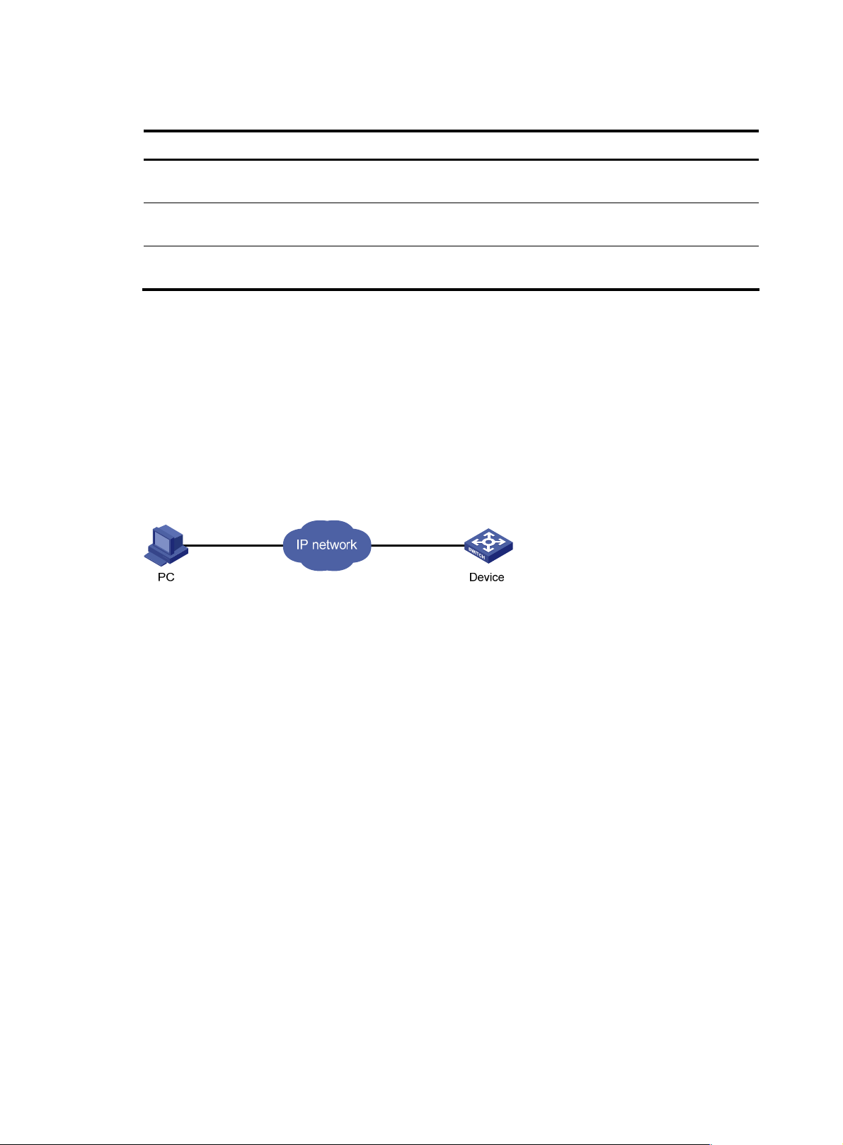
Displaying and maintaining web login
To do… Use the command… Remarks
Display information about web
users
Display HTTP state information
Display HTTPS state information
Web login example
HTTP login example
Network requirements
As shown in Figure 27, the PC is connected to the device over an IP network. The IP address of the Device
is 192.168.20.66/24.
Figure 27 Network diagram for configuring HTTP login
display web users [ | { begin | exclude |
include } regular-expression ]
display ip http [ | { begin | exclude |
include } regular-expression ]
display ip https [ | { begin | exclude |
include } regular-expression ]
Available in any view
Available in any view
Available in any view
Configuration procedure
1. Configuration on the device
# Log in to the device via the console port and configure the IP address of VLAN 1 of the device. VLAN
1 is the default VLAN.
<Sysname> system-view
[Sysname] interface vlan-interface 1
[Sysname-VLAN-interface1] ip address 192.168.20.66 255.255.255.0
[Sysname-VLAN-interface1] quit
# Create a local user named admin, and set the password to admin for the user. Specify the Telnet
service type for the local user, and set the command level to 3 for this user.
[Sysname] local-user admin
[Sysname-luser-admin] service-type telnet
[Sysname-luser-admin] authorization-attribute level 3
[Sysname-luser-admin] password simple admin
2. Configuration on the PC
# On the PC, run the web browser. Enter the IP address of the device in the address bar, 192.168.20.66
in this example. The web login page appears, as shown in Figure 28.
70
Page 78

Figure 28 Web login page
# Type the user name, password, verify code, select English, and click Login. The homepage appears.
After login, you can configure device settings through the web interface.
HTTPS login example
Network requirements
As shown in Figure 29, to prevent unauthorized users from accessing the Device, configure HTTPS login
as follows:
• Configure the Device as the HTTPS server, and request a certificate for it.
• The Host acts as the HTTPS client. Request a certificate for it.
In this example, Windows Server acts as the CA. Install Simple Certificate Enrollment Protocol (SCEP)
add-on on the CA. The name of the CA that issues certificates to the Device and Host is new-ca.
Before performing the following configuration, make sure that the Device, Host, and CA can reach each
other.
Figure 29 Network diagram for configuring HTTPS login
71
Page 79

Configuration procedure
1. Configure the device that acts as the HTTPS server
# Configure a PKI entity, configure the common name of the entity as http-server1, and the FQDN of the
entity as ssl.security.com.
<Device> system-view
[Device] pki entity en
[Device-pki-entity-en] common-name http-server1
[Device-pki-entity-en] fqdn ssl.security.com
[Device-pki-entity-en] quit
# Create a PKI domain, specify the trusted CA as new-ca, the URL of the server for certificate request as
http://10.1.2.2/certsrv/mscep/mscep.dll, authority for certificate request as RA, and the entity for
certificate request as en.
[Device] pki domain 1
[Device-pki-domain-1] ca identifier new-ca
[Device-pki-domain-1] certificate request url http://10.1.2.2/certsrv/mscep/mscep.dll
[Device-pki-domain-1] certificate request from ra
[Device-pki-domain-1] certificate request entity en
[Device-pki-domain-1] quit
# Create RSA local key pairs.
[Device] public-key loc al create rsa
# Retrieve the CA certificate from the certificate issuing server.
[Device] pki retrieval-certificate ca domain 1
# Request a local certificate from a CA through SCEP for the device.
[Device] pki request-certificate domain 1
# Create an SSL server policy myssl, specify PKI domain 1 for the SSL server policy, and enable
certificate-based SSL client authentication.
[Device] ssl server-policy myssl
[Device-ssl-server-policy-myssl] pki-domain 1
[Device-ssl-server-policy-myssl] client-verify enable
[Device-ssl-server-policy-myssl] quit
# Create a certificate attribute group mygroup1, and configure a certificate attribute rule, specifying that
the Distinguished Name (DN) in the subject name includes the string of new-ca.
[Device] pki certificate attribute-group mygroup1
[Device-pki-cert-attribute-group-mygroup1] attribute 1 issuer-name dn ctn new-ca
[Device-pki-cert-attribute-group-mygroup1] quit
# Create a certificate attribute-based access control policy myacp. Configure a certificate
attribute-based access control rule, specifying that a certificate is considered valid when it matches an
attribute rule in certificate attribute group myacp.
[Device] pki certificate access-control-policy myacp
[Device-pki-cert-acp-myacp] rule 1 permit mygroup1
[Device-pki-cert-acp-myacp] quit
# Associate the HTTPS service with SSL server policy myssl.
[Device] ip https ssl-server-policy myssl
# Associate the HTTPS service with certificate attribute-based access control policy myacp.
[Device] ip https certificate access-control-policy myacp
72
Page 80

g
NOTE:
# Enable the HTTPS service.
[Device] ip https enable
# Create a local user named usera, set the password to 123 for the user, and specify the Telnet service
type for the local user.
[Device] local-user usera
[Device-luser-usera] password simple 123
[Device-luser-usera] service-type telnet
2. Configure the host that acts as the HTTPS client
On the host, run the IE browser. In the address bar, enter http://10.1.2.2/certsrv and request a certificate
for the host as prompted.
3. Verify the configuration
Enter http s: // 10 .1.1.1 in the address bar, and select the certificate issued by new-ca. Then the web login
page of the Device appears. On the login page, type the username usera, and password 12 3 to enter
the web management page.
• To log in to the web interface through HTTPS, enter the URL address starting with https://. To lo
the web interface through HTTP, enter the URL address starting with http://.
• For more information about PKI configuration commands, see the
• For more information about the public-key local create rsa command, see the
Reference
.
• For more information about SSL configuration commands, see the
Security Command Reference
Security Command
Security Command Reference
in to
.
.
73
Page 81

NMS login
NMS login overview
An NMS runs the SNMP client software. It offers a user-friendly interface to facilitate network
management. An agent is a program that resides in the device. It receives and handles requests from the
NMS. An NMS is a manager in an SNMP enabled network, whereas agents are managed by the NMS.
The NMS and agents exchange information through the SNMP protocol. The device supports multiple
NMS programs, such as iMC and CAMS.
By default, you cannot log in to the device through NMS. To enable NMS login, log in to the device via
the console port and make the configuration changes described in the following table.
The following table shows the configuration requirements of NMS login.
Object Requirements
Configure the IP address of the VLAN interface
Device
Make sure the device and the NMS can reach each other
Configure SNMP settings
NMS Configure the NMS. For more information, see your NMS manual.
Configuring NMS login
Connect the Ethernet port of the PC to an Ethernet port of VLAN 1 of the device, as shown in Figure 30.
Make sure the PC and VLAN 1 interface can reach each other.
Figure 30 Network diagram for configuring NMS login
Follow these steps to configure SNMPv3 settings:
To do… Use the command… Remarks
Enter system view system-view —
Enable SNMP agent snmp-agent
Optional
Disabled by default.
You can enable SNMP agent with this
command or any command that
begins with snmp-agent.
Configure an SNMP group
and specify its access right
snmp-agent group v3 group-name
[ authentication | privacy ]
[ read-view read-view ] [ write-view
write-view ] [ notify-view
notify-view ] [ acl acl-number ]
74
Required
By default, no SNMP group is
configured.
Page 82

To do… Use the command… Remarks
Add a user to the SNMP group
snmp-agent usm-user v3 user-name
group-name [ [ cipher ]
authentication-mode { md5 | sha }
auth-password [ privacy-mode
{ 3des | aes128 | des56 }
priv-password ] ] [ acl acl-number ]
Required
If the cipher keyword is specified, both
auth-password and priv-password are
cipher text passwords.
Follow these steps to configure SNMPv1 and SNMPv2c settings:
To do… Use the command… Remarks
Enter system view system-view —
Optional
Disabled by default.
Enable SNMP agent snmp-agent
snmp-agent mib-view
Create or update MIB view information
Configure an
Directly
Configure
SNMP NMS
access right
Indirectly
SNMP
community
Configure an
SNMP group
Add a user to the
SNMP group
{ excluded | included }
view-name oid-tree [ mask
mask-value ]
snmp-agent community
{ read | write }
community-name [ acl
acl-number | mib-view
view-name ]*
snmp-agent group { v1 |
v2c } group-name
[ read-view read-view ]
[ write-view write-view ]
[ notify-view notify-view ]
[ acl acl-number ]
snmp-agent usm-user { v1 |
v2c } user-name group-name
[ acl acl-number ]
You can enable SNMP agent
with this command or any
command that begins with
snmp-agent.
Optional
By default, the MIB view
name is ViewDefault and
OID is 1.
Required
Use either approach.
The direction configuration
approach is for SNMPv1 or
SNMPv2c. The community
name configured on the
NMS should be consistent
with the username configured
on the agent.
The indirect configuration
approach is for SNMPv3.
NOTE:
The device supports the following SNMP versions: SNMPv1, SNMPv2c and SNMPv3. For more
information about SNMP, see the
Network Management and Monitoring Configuration Guide
.
NMS login example
In this example, iMC is used as the NMS.
1. Configuration on the device
# Assign IP address of device. Make sure the device and the NMS can reach each other. (Configuration
steps are omitted.)
75
Page 83

# Enter system view.
<Sysname> system-view
# Enable the SNMP agent.
[Sysname] snmp-agent
# Configure an SNMP group.
[Sysname] snmp-agent group v3 managev3group read-view test write-view test
# Add a user to the SNMP group.
[Sysname] snmp-agent usm-user v3 managev3user managev3group
2. Configuration on the NMS
On the PC, start the browser. In the address bar, enter http://192.168.20.107:8080/imc, where
192.168.20.107 is the IP address of the iMC.
Figure 31 iMC login page
Type the username and password, and then click Login. The iMC homepage appears, as shown in Figure
32.
76
Page 84

Figure 32 iMC homepage
Log in to the iMC and configure SNMP settings for the iMC to find the device. After the device is found,
you can manage and maintain the device through the iMC. For example, you can query device
information or configure device parameters.
The SNMP settings on the iMC must be the same as those configured on the device. If not, the device
cannot be found or managed by the iMC. See the iMC manuals for more information.
Click Help in the upper right corner of each configuration page to get corresponding help information.
77
Page 85

User login control
User login control methods
The device provides the following login control methods.
Login Through Login control methods ACL used
Telnet
NMS
Web
Configuring source IP-based login control over Telnet users
Configuring source and destination IP-based login
control over Telnet users
Configuring source MAC-based login control over
Telnet users
Configuring source IP-based login control over NMS
users
Configuring source IP-based login control over web
users
Basic ACL
Advanced ACL
Ethernet frame header ACL
Basic ACL
Basic ACL
Configuring login control over Telnet users
Configuration preparation
Before configuration, determine the permitted or denied source IP addresses, source MAC addresses,
and destination IP addresses.
Configuring source IP-based login control over Telnet users
Because basic ACLs match the source IP addresses of packets, you can use basic ACLs to implement
source IP-based login control over Telnet users. Basic ACLs are numbered from 2000 to 2999. For more
information about ACL, see the ACL and QoS Configuration Guide.
Follow these steps to configure source IP-based login control over Telnet users:
To do… Use the command… Remarks
Enter system view system-view —
Create a basic ACL and enter its
view, or enter the view of an
existing basic ACL
Configure rules for this ACL
Exit the basic ACL view
acl [ ipv6 ] number acl-number
[ match-order { config | auto } ]
rule [ rule-id ] { permit | deny }
[ source { sour-addr sour-wildcard
| any } | time-range time-name |
fragment | logging ]*
quit —
78
Required
By default, no basic ACL exists.
Required
Page 86

To do… Use the command… Remarks
Enter user interface view
Use the ACL to control user login
by source IP address
user-interface [ type ] first-number
[ last-number ]
acl [ ipv6 ] acl-number { inbound |
outbound }
—
Required
inbound: Filters incoming Telnet
packets.
outbound: Filters outgoing Telnet
packets.
Configuring source and destination IP-based login control over Telnet users
Because advanced ACLs can match both source and destination IP addresses of packets, you can use
advanced ACLs to implement source and destination IP-based login control over Telnet users. Advanced
ACLs are numbered from 3000 to 3999. For more information about ACL, see the ACL and QoS
Configuration Guide.
Follow these steps to configure source and destination IP-based login control over Telnet users:
To do… Use the command… Remarks
Enter system view system-view —
Create an advanced ACL
and enter its view, or enter
the view of an existing
advanced ACL
acl [ ipv6 ] number acl-number
[ match-order { config | auto } ]
Required
By default, no advanced ACL
exists.
Configure rules for the ACL rule [ rule-id ] { permit | deny } rule-string Required
Exit advanced ACL view quit —
Enter user interface
Use the ACL to control user
login by source and
destination IP addresses
user-interface [ type ] first-number
[ last-number ]
acl [ ipv6 ] acl-number { inbound |
outbound }
—
Required
inbound: Filters incoming Telnet
packets.
outbound: Filters outgoing Telnet
packets.
Configuring source MAC-based login control over Telnet users
Ethernet frame header ACLs can match the source MAC addresses of packets, so you can use Ethernet
frame header ACLs to implement source MAC-based login control over Telnet users. Ethernet frame
header ACLs are numbered from 4000 to 4999. For more information about ACL, see the ACL and QoS
Configuration Guide.
Follow these steps to configure source MAC-based login control over Telnet users:
To do… Use the command… Remarks
Enter system view system-view —
79
Page 87

To do… Use the command… Remarks
Create an Ethernet frame header
ACL and enter its view
Configure rules for the ACL
Exit the advanced ACL view quit —
Enter user interface view
Use the ACL to control user login
by source MAC address
acl number acl-number
[ match-order { config | auto } ]
rule [ rule-id ] { permit | deny }
rule-string
user-interface [ type ] first-number
[ last-number ]
acl acl-number inbound
Required
By default, no advanced ACL
exists.
Required
—
Required
inbound: Filters incoming Telnet
packets.
NOTE:
The above configuration does not take effect if the Telnet client and server are not in the same subnet.
Source MAC-based login control configuration example
Network requirements
As shown in Figure 33, configure an ACL on the Device to permit only incoming Telnet packets sourced
from Host A and Host B.
Figure 33 Network diagram for configuring source MAC-based login control
Configuration procedure
# Configure basic ACL 2000, and configure rule 1 to permit packets sourced from Host B, and rule 2 to
permit packets sourced from Host A.
<Sysname> system-view
[Sysname] acl number 2000 match-order config
[Sysname-acl-basic-2000] rule 1 permit source 10.110.100.52 0
[Sysname-acl-basic-2000] rule 2 permit source 10.110.100.46 0
[Sysname-acl-basic-2000] quit
# Reference ACL 2000 in user interface view to allow Telnet users from Host A and Host B to access the
Device.
80
Page 88

[Sysname] user-interface vty 0 4
[Sysname-ui-vty0-4] acl 2000 inbound
Configuring source IP-based login control over NMS users
You can log in to the NMS to remotely manage the devices. SNMP is used for communication between
the NMS and the agent that resides in the device. By using the ACL, you can control SNMP user access
to the device.
Configuration preparation
Before configuration, determine the permitted or denied source IP addresses.
Configuring source IP-based login control over NMS users
Because basic ACLs match the source IP addresses of packets, you can use basic ACLs to implement
source IP-based login control over NMS users. Basic ACLs are numbered from 2000 to 2999. For more
information about ACL, see the ACL and QoS Configuration Guide.
Follow these steps to configure source IP-based login control over NMS users:
To do… Use the command… Remarks
Enter system view system-view —
Create a basic ACL and enter its
view, or enter the view of an
existing basic ACL
Create rules for this ACL
Exit the basic ACL view quit —
Associate this SNMP community
with the ACL
Associate the SNMP group with
the ACL
acl [ ipv6 ] number acl-number
[ match-order { config | auto } ]
rule [ rule-id ] { permit | deny }
[ source { sour-addr sour-wildcard |
any } | time-range time-name |
fragment | logging ]*
snmp-agent community { read |
write } community-name [ acl
acl-number | mib-view
view-name ]*
snmp-agent group { v1 | v2c }
group-name [ read-view
read-view ] [ write-view
write-view ] [ notify-view
notify-view ] [ acl acl-number ]
snmp-agent group v3 group-name
[ authentication | privacy ]
[ read-view read-view ]
[ write-view write-view ]
[ notify-view notify-view ] [ acl
acl-number ]
Required
By default, no basic ACL exists.
Required
Required
You can associate the ACL when
creating the community, the SNMP
group, and the user.
For more information about
SNMP, see the Network
Management and Monitoring
Configuration Guide.
81
Page 89

To do… Use the command… Remarks
snmp-agent usm-user { v1 | v2c }
user-name group-name [ acl
acl-number ]
Associate the user with the ACL
snmp-agent usm-user v3
user-name group-name [ [ cipher ]
authentication-mode { md5 | sha }
auth-password [ privacy-mode
{ 3des | aes128 | des56 }
priv-password ] ] [ acl acl-number ]
Source IP-based login control over NMS users configuration example
Network requirements
As shown in Figure 34, configure the device to allow only NMS users from Host A and Host B to access.
Figure 34 Network diagram for configuring source IP-based login control over NMS users
Configuration procedure
# Create ACL 2000, and configure rule 1 to permit packets sourced from Host B, and rule 2 to permit
packets sourced from Host A.
<Sysname> system-view
[Sysname] acl number 2000 match-order config
[Sysname-acl-basic-2000] rule 1 permit source 10.110.100.52 0
[Sysname-acl-basic-2000] rule 2 permit source 10.110.100.46 0
[Sysname-acl-basic-2000] quit
# Associate the ACL with the SNMP community and the SNMP group.
[Sysname] snmp-agent community read aaa acl 2000
[Sysname] snmp-agent group v2c groupa acl 2000
[Sysname] snmp-agent usm-user v2c usera groupa acl 2000
82
Page 90

Configuring source IP-based login control over web users
You can log in to the we b management page of the devic e throug h HTT P/HTTPS to remote ly manage the
devices. By using the ACL, you can control web user access to the device.
Configuration preparation
Before configuration, determine the permitted or denied source IP addresses.
Configuring source IP-based login control over web users
Because basic ACLs match the source IP addresses of packets, you can use basic ACLs to implement
source IP-based login control over web users. Basic ACLs are numbered from 2000 to 2999. For more
information about ACL, see the ACL and QoS Configuration Guide.
Follow these steps to configure source IP-based login control over web users:
To do… Use the command… Remarks
Enter system view system-view —
Create a basic ACL and enter its
view, or enter the view of an
existing basic ACL
Create rules for this ACL
Exit the basic ACL view
Associate the HTTP service with the
ACL
Associate the HTTPS service with
the ACL
acl [ ipv6 ] number acl-number
[ match-order { config | auto } ]
rule [ rule-id ] { permit | deny }
[ source { sour-addr sour-wildcard
| any } | time-range time-name |
fragment | logging ]*
quit —
ip http acl acl-number
ip https acl acl-number
Logging off online web users
Follow the step to log off online web users:
To do… Use the command… Remarks
Log off online web users
free web-users { all | user-id
user-id | user-name user-name }
Required
By default, no basic ACL exists.
Required
Required to use one command
Required
Execute the command in user
interface view.
83
Page 91

Source IP-based login control over web users configuration example
Network requirements
As shown in Figure 35, configure the device to allow only web users from Host B to access.
Figure 35 Network diagram for configuring source IP-based login control
Configuration procedure
# Create ACL 2000, and configure rule 1 to permit packets sourced from Host B.
<Sysname> system-view
[Sysname] acl number 2030 match-order config
[Sysname-acl-basic-2030] rule 1 permit source 10.110.100.52 0
# Associate the ACL with the HTTP service so that only web users from Host B are allowed to access the
device.
[Sysname] ip http acl 2030
84
Page 92

FTP configuration
FTP overview
Introduction to FTP
The File Transfer Protocol (FTP) is an application layer protocol for sharing files between server and client
over a TCP/IP network.
FTP uses TCP ports 20 and 21 for file transfer. Port 20 is used to transmit data, and port 21 to transmit
control commands. For more information about FTP basic operations, see RFC 959.
FTP transfers files in the following modes:
• Binary mode: Transfers files as raw data, such as .app, .bin, and .btm files.
• ASCII mode: Transfers files as text, such as .txt, .bat, and .cfg files.
FTP operation
FTP adopts the client/server model. Your device can function either as the client or the server. See Figure
36.
• When the device serves as the FTP client, use Telnet or an emulation program to log in to the device
from the PC, execute the ftp command to establish a connection from the device (FTP client) to the
PC (FTP server), and then upload/download files to/from the server.
• When the device serves as the FTP server, run the FTP client program on the PC to establish a
connection to the FTP server and upload/download files to/from the server.
Figure 36 Network diagram for FTP
When the device serves as the FTP client, you need to perform the following configuration:
Table 8 Configuration when the device serves as the FTP client
Device Configuration Remarks
Device (FTP client)
Use the ftp command to establish the
connection to the remote FTP server
If the remote FTP server supports anonymous
FTP, the device can log in to it directly; if not,
the device must obtain the FTP username and
password first to log in to the remote FTP
server.
Enable FTP server on the PC, and
PC (FTP server)
When the device serves as the FTP server, you need to perform the following configuration:
configure the username, password,
user privilege level, and so on.
85
—
Page 93

Table 9 Configuration when the device serves as the FTP server
Device Configuration Remarks
Disabled by default.
Device (FTP
server)
Enable the FTP server function
Configure authentication and
authorization
You can use the display ftp-server command to view the
FTP server configuration on the device.
Configure the username, password, and authorized
directory for an FTP user.
The device does not support anonymous FTP for security
reasons. You must set a valid username and password.
By default, authenticated users can access the root
directory of the device.
Configure the FTP server
operating parameters
PC (FTP client)
CAUTION:
Use the FTP client program to log
in to the FTP server.
• Make sure that the FTP server and the FTP client can reach each other before establishing the FTP
connection.
• When you use IE to log in to the device serving as the FTP server, some FTP functions are not available.
This is because multiple connections are established during the login process but the device supports
only one connection at a time.
Configuring the FTP client
NOTE:
Only manage level users can use the ftp command to log in to an FTP server, enter FTP client view, and
execute directory and file related commands. However, whether the commands can be executed
successfully depends on the FTP server authorizations.
Parameters such as the FTP connection timeout time
You can log in to the FTP server only after you input the
correct FTP username and password.
Establishing an FTP connection
Before you can access the FTP server, you must first establish a connection from the FTP client to the FTP
server. You can either use the ftp comm and to es tablish the c onnect ion directly or use the open command
in FTP client view to establish the connection.
When using the ftp command, you can specify the source interface (such as a loopback) or source IP
address. The primary IP address of the specified source interface or the specified source IP address is
used as the source IP address of sent FTP packets. The source address of the transmitted packets is
selected following these rules:
• If no source address is specified, the FTP client uses the interface’s IP address determined by the
matched route as the source IP address to communicate with an FTP server.
• If the source address is specified with the ftp client source or ftp command, this source address is
used to communicate with an FTP server.
86
Page 94

g
• If you use the ftp client source command and the ftp command to specify a source address
respectively, the source address specified with the ftp com mand i s used to communic ate with a n FTP
server.
• The source address specified with the ftp client source command is valid for all FTP connections and
the source address specified with the ftp command is valid only for the current FTP connection.
Follow these steps to establish an IPv4 FTP connection:
To do… Use the command… Remarks
Enter system view system-view —
Optional
A switch uses the IP address
Configure the source address of
the FTP client
Exit to system view quit —
Log in to the remote FTP server
directly in user view
Log in to the remote FTP server
indirectly in FTP client view
ftp client source { interface interface-type
interface-number | ip source-ip-address }
ftp [ server-address [ service-port ]
[ source { interface interface-type
interface-number | ip
source-ip-address } ] ]
ftp
open server-address [ service-port ]
of the interface determined by
the matched route as the
source IP address to
communicate with the FTP
server by default.
Use either approach.
The ftp command is available
in user view, and the open
command is available in FTP
client view.
NOTE:
• If there is not a primary IP address configured on the specified source interface, you cannot establish an
FTP connection.
• If you use the ftp client source command to confi
ure a source interface and then use it to configure a
source IP address, the source IP address overwrites the source interface, and vice versa.
Follow these steps to establish an IPv6 FTP connection:
To do… Use the command… Remarks
ftp ipv6 [ server-address
Log in to the remote FTP server
directly in user view
Log in to the remote FTP server
indirectly in FTP client view
[ service-port ] [ source ipv6
source-ipv6-address ] [ -i
interface-type interface-number ] ]
ftp ipv6
open ipv6 server-address
[ service-port ] [ -i interface-type
interface-number ]
Operating the directories on an FTP server
After the switch serving as the FTP client has established a connection with an FTP server, you can create
or delete folders under the authorized directory of the FTP server. For more information about establishing
an FTP connection, see “Establishing an FTP connection.”
Use either approach.
The ftp ipv6 command is available
in user view; and the open ipv6
command is available in FTP client
view.
87
Page 95

Follow these steps to operate the directories on an FTP server:
To do… Use the command… Remarks
Display detailed information about a directory or
file on the remote FTP server
Query a directory or file on the remote FTP server ls [ remotefile [ localfile ] ] Optional
Change the working directory of the remote FTP
server
Exit the current working directory and return to an
upper level directory of the remote FTP server
Display the working directory that is being
accessed
Create a directory on the remote FTP server mkdir directory Optional
Remove the specified working directory on the
remote FTP server
dir [ remotefile [ localfile ] ] Optional
cd { directory | .. | / } Optional
cdup Optional
pwd Optional
rmdir directory Optional
Operating the files on an FTP server
After the switch serving as the FTP client has established a connection with an FTP server, you can upload
a file to or download a file from the FTP server under the authorized directory of the FTP server by
following these steps. For information about establishing an FTP connection, see “Establishing an FTP
connection.”
1. Use the dir or ls command to display the directory and the location of the file on the FTP server.
2. Delete useless files for effective use of the storage space.
3. Set the file transfer mode. FTP transmits files in two modes: ASCII and binary. ASCII mode transfers
files as text. Binary mode transfers files as raw data.
4. Use the lcd command to display the local working directory of the FTP client. You can upload the
file under this directory, or save the downloaded file under this directory.
5. Upload or download the file.
Follow these steps to operate the files on an FTP server:
To do… Use the command… Remarks
Optional
Display detailed information
about a directory or file on the
remote FTP server
Query a directory or file on the
remote FTP server
Delete the specified file on the
remote FTP server permanently
dir [ remotefile [ localfile ] ]
ls [ remotefile [ localfile ] ]
delete remotefile Optional
The ls command displays the name of a
directory or file only, while the dir
command displays detailed information
such as the file size and creation time.
Optional
The ls command displays the name of a
directory or file only, while the dir
command displays detailed information
such as the file size and creation time.
Set the file transfer mode to
ASCII
ascii
Optional
ASCII by default.
88
Page 96

To do… Use the command… Remarks
Set the file transfer mode to
binary
Set the data transmission mode
to passive
Display the local working
directory of the FTP client
Upload a file to the FTP server put localfile [ remotefile ] Optional
Download a file from the FTP
server
binary
passive
lcd Optional
get remotefile [ localfile ] Optional
Optional
ASCII by default.
Optional
Passive by default.
Using another username to log in to an FTP server
After the switch serving as the FTP client has established a connection with the FTP server, you can use
another username to log in to the FTP server. For more information about establishing an FTP connection,
see “Establishing an FTP connection.”
Th is feat ure allows you to switch to diffe rent user levels without a ffectin g the current FTP con nection ; if you
input an incorrect username or password, the current connection will be terminated, and you must log in
again to access the FTP server.
Follow the step below to use another username to log in to the FTP server:
To do… Use the command… Remarks
Use another username to re-log in after
successfully logging in to the FTP server
user username [ password ] Optional
Maintaining and debugging an FTP connection
After a switch serving as the FTP client has established a connection with the FTP server, you can perform
the following operations to locate and diagnose problems encountered in an FTP connection. For more
information about establishing an FTP connection, see “Establishing an FTP connection.”
To do… Use the command… Remarks
Display the help information of
FTP-related commands supported by the
remote FTP server
Enable information display in a detailed
manner
Enable FTP related debugging when the
switch acts as the FTP client
remotehelp [ protocol-command ] Optional
verbose
debugging
Optional
Enabled by default
Optional
Disabled by default
Terminating an FTP connection
After the switch serving as the FTP client has established a connection with the FTP server, you can use
any of the following commands to terminate an FTP connection. For more information about establishing
an FTP connection, see “Establishing an FTP connection.”
89
Page 97

y
g
To do… Use the command… Remarks
Terminate the connection to the FTP server
without exiting FTP client view
Terminate the connection to the FTP server
without exiting FTP client view
Terminate the connection to the FTP server
and return to user view
Terminate the connection to the FTP server
and return to user view
disconnect
close
bye
quit
FTP client configuration example
Network requirements
• As shown in Figure 37, use the device as an FTP client and the PC as the FTP server. Their IP
addresses are 10.2.1.1/16 and 10.1.1.1/16 respectively. The device and PC can reach each other.
• The device downloads a system software image file from the PC for device upgrade, and uploads
the configuration file to the PC for backup.
Optional
Equal to the close command.
Optional
Equal to the disconnect
command.
Optional
Equal to the quit command in
FTP client view.
Optional
Available in FTP client view,
equal to the bye command.
• On the PC, an FTP user account has been created for the FTP client, with the username abc and the
password pwd.
Figure 37 Network diagram for FTPing a system software image file from an FTP server
Configuration procedure
CAUTION:
If the available memory space of the device is not enough, use the fixdisk
or use the delete /unreserved
operations.
# Log in to the server through FTP.
<Sysname> ftp 10.1.1.1
Trying 10.1.1.1
Connected to 10.1.1.1
220 WFTPD 2.0 service (by Texas Imperial Software) ready for new user
User(10.1.1.1:(none)):abc
331 Give me your password, please
Password:
command to clear the memor
file-url
command to delete the files not in use and then perform the followin
90
Page 98

230 Logged in successfully
# Set the file transfer mode to binary to transmit system software image file.
[ftp] binary
200 Type set to I.
# Download the system software image file newest.bin from the PC to the device.
[ftp] get newest.bin
# Upload the configuration file config.cfg of the device to the server for backup.
[ftp] ascii
[ftp] put config.cfg back-config.cfg
227 Entering Passive Mode (10,1,1,1,4,2).
125 ASCII mode data connection already open, transfer starting for /config.cfg.
226 Transfer complete.
FTP: 3494 byte(s) sent in 5.646 second(s), 618.00 byte(s)/sec.
[ftp] bye
# Specify newest.bin as the main system software image file for next startup.
<Sysname> boot-loader file newest.bin main
# Reboot the device, and the system software image file is updated at the system reboot.
<Sysname> reboot
CAUTION:
The system software image file for next startup must be saved in the storage medium’s root directory. You
can copy or move a file to the storage medium’s root directory. For more information about the
boot-loader command, see
the
Fundamentals Command Reference.
Configuring the FTP server
Configuring FTP server operating parameters
The FTP server uses one of the following modes to update a file when you upload the file (use the put
command) to the FTP server:
• In fast mode, the FTP server starts writing data to the storage medium after a file is transferred to the
memory. This prevents the existing file on the FTP server from being corrupted in the event that
anomaly, such as a power failure occurs during a file transfer.
• In normal mode, the FTP server writes data to the storage medium while receiving data. This means
that any anomaly, such as a power failure during file transfer might result in file corruption on the
FTP server. This mode, however, consumes less memory space than the fast mode.
Follow these steps to configure the FTP server:
To do… Use the command… Remarks
Enter system view system-view —
Enable the FTP server ftp server enable
91
Required
Disabled by default.
Page 99

To do… Use the command… Remarks
Use an ACL to control FTP clients’
access to the switch
Configure the idle-timeout timer ftp timeout minutes
Set the file update mode for the FTP
server
Quit to user view quit —
Manually release the FTP
connection established with the
specified username
ftp server acl acl-number
ftp update { fast | normal }
free ftp user username
Optional
By default, no ACL is used to control
FTP clients’ access to the switch.
Optional
30 minutes by default.
Within the idle-timeout time, if there is
no information interaction between
the FTP server and client, the
connection between them is
terminated.
Optional
Normal update is used by default.
Optional
Available in user view
Configuring authentication and authorization on the FTP server
To allow an FTP user to access certain directories on the FTP server, you must create an account for the
user, authorizing access to the directories and associating the username and password with the account.
The following configuration is used when the FTP server authenticates and authorizes a local FTP user. If
the FTP server needs to authenticate a remote FTP user, you must configure authentication, authorization
and accounting (AAA) policy instead of the local user. For detailed configuration, see the Security
Command Reference.
In local authentication, the switch checks the input username and password against those configured on
the switch. In remote authentication, the switch sends the input username and password to the remote
authentication server, which then checks whether they are consistent with those configured on the switch.
Follow these steps to configure authentication and authorization for FTP server:
To do… Use the command… Remarks
Enter system view system-view —
Required
Create a local user and enter its
view
Assign a password to the user
Assign the FTP service to the user service-type ftp
local-user user-name
password { simple | cipher }
password
No local user exists by default, and
the system does not support FTP
anonymous user access.
Required
Required
By default, the system does not
support anonymous FTP access,
and does not assign any service. If
the FTP service is assigned, the root
directory of the switch is used by
default.
92
Page 100

g
To do… Use the command… Remarks
authorization-attribute { acl
acl-number | callback-number
callback-number | idle-cut minute
Configure user properties
| level level | user-profile
profile-name | user-role
security-audit | vlan vlan-id |
work-directory directory-name } *
NOTE:
• For more information about the local-user, password, service-type ftp, and authorization-attribute
commands, see the
Security Command Reference
• When the switch serves as the FTP server, if the client is to perform the write operations (such as upload,
delete, and create) on the device’s file system, the FTP lo
perform other operations such as the
read operation, the switch has no restriction on the user level of the
FTP login users.
FTP server configuration example
Network requirements
• As shown in Figure 38, use the device as an FTP server, and the PC as the FTP client. Their IP
addresses are 1.2.1.1/16 and 1.1.1.1/16 respectively. The device and PC can reach each other.
Optional
By default, the FTP/SFTP users can
access the root directory of the
switch, and the user level is 0. You
can change the default
configuration by using this
command.
.
in users must be level 3 users; if the client is to
• PC keeps the updated system software image file of the device. Use FTP to upgrade the device and
back up the configuration file.
• Set the username to ftp and the password to pwd for the FTP client to log in to the FTP server.
Figure 38 Upgrading using the FTP server
Configuration procedure
1. Configure the device (FTP Server)
# Create an FTP user account ftp, set its password to pwd and the user privilege level to level 3 (the
manage level). Allow user ftp to access the root directory of the flash, and specify ftp to use FTP.
<Sysname> system-view
[Sysname] local-user ftp
[Sysname-luser-ftp] password simple pwd
[Sysname-luser-ftp] authorization-attribute level 3
[Sysname-luser-ftp] authorization-attribute work-directory flash:/
[Sysname-luser-ftp] service-type ftp
[Sysname-luser-ftp] quit
# Enable FTP server.
[Sysname] ftp server enable
[Sysname] quit
93
 Loading...