

Page 1
owner’s manual
Owner’s Manual
Manuel du propriétaire
Manual del propietario
Manual do Proprietário
HP
J1473A 4-port Console Switch
HP
J1474A 8-port Console Switch
HP
J1475A Console Switch Expansion Kit
Page 2

©2001 Hewlett-Packard Company. All rights reserved.
IBM, PC/AT and PS/2 are registered trademarks of International Business Machines Corporation. ScrollPoint is a trademark
of International Business Machines Corporation. Expert Mouse is a registered trademark of Kensington Technology Group.
Microsoft, Logitech and Kensington are registered trademarks of their respective companies. MouseMan, Marble and
TrackMan are registered trademarks of Logitech, Inc. IntelliMouse is a trademark of Microsoft Corporation.
Hewlett-Packard Company
www.hp.com
Page 3

War ning: Changes or modifi cations to this unit not expressly approved by the
party responsible for compliance could void the user's authority to operate
the equipment.
Note: This equipment has been tested and found to comply with the limits for
a Class A digital device, pursuant to Part 15 of the FCC Rules. These limits are
designed to provide reasonable protection against harmful interference when the
equipment is operated in a commercial environment. This equipment generates,
uses and can radiate radio frequency energy and, if not installed and used in
accordance with the instruction manual, may cause harmful interference to radio
communications. Operation of this equipment in a residential area is likely to
cause harmful interference in which case the user will be required to correct the
interference at his own expense.
This digital apparatus does not exceed the Class A limits for radio noise emissions
from digital apparatus set out in the Radio Interference Regulations of the
Canadian Department of Communications.
Le présent appareil numérique n'émet pas de bruits radioélectriques les limites
applicables aux appareils numériques de la class A prescrites dans le Règlement
sur le brouillage radioélectrique édicté par le Ministère des Communications
du Canada.
FCC Notifi cation
Canadian Notifi cation
Japan - VCCI Class A ITE
Page 4

Rackmount Console Switch Owner’s Manual
Declaration of Conformity
(according to ISO/IEC Guide 22 and EN45014)
Manufacturer’s Name: Hewlett-Packard
Manufacturer’s Address: 10955 N. Tantau Avenue
Cupertino, CA 95014-0770 U.S.A.
Declares that the product:
Product Name: Rackmount Console Switch 4-Port / 8-Port / Expansion
Product Type: Console Controllers
Model Numbers: J1473A / J1474A / J1475A
Product Options: All
Conforms to the following Product Specifi cations:
Safety: IEC 950:1991+A1+A2+A3+A4
EN 60950:1992+A1+A2+A3+A4
EMC: CISPR 22:1993 / EN 55022:1994 - Class A
(1)
EN 50082-1:1992
IEC 801-2:1991 / prEN 55024-2:1992 - 4kV CD, 8kV AD
IEC 801-3:1984 / prEN 55024-3:1991 - 3V/m
IEC 801-4:1988 / prEN 50024-4:1992 - 1kV power lines
- 0.5kV signal lines
Supplementary Information:
The product herewith complies with the requirements of the Low Voltage Directive
73/23/EEC and 93/68/EEC and the EMC Directive 89/336/EEC and 92/31/EEC and
93/68/EEC and carries the CE Marking, accordingly.
(1)
The product was tested in a typical confi guration with a Hewlett-Packard computer system.
Cupertino, CA, USA November 1, 1999
_________________ _________________ _____________________________
Location Date John McBain, Sr. Quality Engineer
Only for Regulatory Compliance Information:
European Contact: Your local Hewlett-Packard Sales & Service Offi ce or Hewlett-Packard GmbH,
Department HQ-TRE / Standards Europe, Herrenberger Strasse 130, D-71034 Böeblingen
(Fax: +49-7031-14-3143).
USA Contact: Hewlett-Packard Company, Regulatory Affairs Offi ce, 3000 Hanover Street,
Palo Alto, CA 94304 (Tel. 650-857-4423).
Page 5

Table of Contents
Chapter 4 - On-Screen Display Operations
Activating OSD ................................................................................................................................17
The OSD Window............................................................................................................................18
The Command Menu .....................................................................................................................19
Basic
Port
Port Maintenance............................................................................................................... 20
The ID Window ............................................................................................................................... 22
Administrator Functions ...............................................................................................................24
Chapter 7 - Appendices
A: Specifi cations ............................................................................................................................. 33
B: FLASH Upgrading..................................................................................................................... 34
C: Troubleshooting......................................................................................................................... 39
D: Problem Report ......................................................................................................................... 44
Chapter 6 - Port Scanning
Choosing a Scanning Method ....................................................................................................31
Turning Scanning On and Off.................................................................................................... 32
Chapter 2 - Installation
Basic Install......................................................................................................................................... 5
Advanced Install .............................................................................................................................12
Chapter 1 - Product Overview
Feature Overview............................................................................................................................... 1
Chapter 3 - Basic Operations
Keyboard Control ............................................................................................................................13
Keyboard Switching........................................................................................................................14
System Control & Maintenance .................................................................................................15
Chapter 5 - Console Switch 2 User Expansion Kit (Optional)
Multiuser Operation.......................................................................................................................27
Multi Chassis Operation .............................................................................................................. 28
Page 6
Rackmount Console Switch Owner’s Manual
INSTRUCTIONS: The exclamation point within an equilateral triangle
is intended to alert the user to the presence of important operating and
maintenance (servicing) instructions in the literature accompanying
the appliance.
DANGEROUS VOLTAGE: The lightning fl ash with arrowhead symbol,
within an equilateral triangle, is intended to alert the user to the presence
of uninsulated “dangerous voltage” within the product's enclosure that
may be of suffi cient magnitude to constitute a risk of electric shock
to persons.
PROTECTIVE GROUNDING TERMINAL: A terminal which must be
connected to earth ground prior to making any other connections to
the equipment.
POWER ON: This symbol indicates the principal on/off switch is in
the on position.
POWER OFF: This symbol indicates the principal on/off switch is in
the off position.
Page 7

www.hp.com/racksolutions
1
Product Overview
1
Feature Overview
The Hewlett-Packard Rackmount Console Switch allows you to control multiple
servers with one keyboard, monitor and mouse. The switch is available in two
models: the J1473A and the J1474A. These models support four and eight attached
servers respectively. Each server can be up to 15 feet away from the switch and
peripherals. The Rackmount Console Switch works with IBM PC/AT and PS/2
systems, and 100% compatible computers with support for VGA, SVGA, XGA
and XGA-II video. PS/2 keyboard and PS/2 mouse peripherals are supported
through the rear of the unit.
The J1473A and J1474A Rackmount Console Switches can be upgraded to support
two simultaneous users in the system by purchasing the J1475A Console Switch
Expansion kit (only available in North America and Latin America). Within the
base unit, the switch performs as a matrix, with both users independently accessing
any of the attached servers at the same time. Your second user can be as far as 500
feet away from the switch. This extension capability lets you place your second
keyboard, monitor and mouse wherever you need them most.
The Rackmount Console Switch is FLASH upgradable. This means that you can
update your fi rmware at any time through a simple serial connection.
The Rackmount Console Switch offers support for numerous mice including:
Microsoft IntelliMouse, IBM ScrollPoint, Logitech MouseMan +, Logitech Marble Plus,
Logitech Marble FX and the Kensington Expert Mouse.
The Rackmount Console Switch supports Plug and Play video and is compliant
with the VESA DDC2B standard.
Share Mode enables two users to view information on a single server at
the same time and allows either user to have keyboard and mouse access
to that server.
Extensive mouse
support
Multiuser, remote
access capability
FLASH upgrade
capability
Plug and play
Share mode
Page 8

Rackmount Console Switch Owner’s Manual
www.hp.com/racksolutions
2
A J1473A Rackmount Console Switch will support up to four attached servers, or
ports - J1474A models support eight. If more ports are needed, multiple units can be
cascaded together for expansion. Up to two tiers of units can be connected for a total
of 16 (J1473A) or 64 (J1474A) attached servers in one system.
The Rackmount Console Switch’s “Keep Alive” feature allows attached servers to
power the unit in the event of a switch power failure. This prevents attached servers
from locking up and keeps you from losing valuable time and data.
Use the advanced multi-level security feature to confi gure and control server
access for every type of user in the system. The administrator has full access
privileges, while individual users can have viewing or viewing/editing capability
for each attached server.
Confi gure and control your switch with on-screen menuing! Name your servers
anything you wish, then select the desired server from an easy-to-use menu.
Servers can be listed by name or by port. Secondary menus let you confi gure and
initiate scanning and other features.
The AutoBoot feature boots all attached servers during initial power-up or after
a power failure. Servers are booted transparently without operator intervention,
and may be powered-up one-at-a-time or all at once. When the power stabilizes,
a port may be selected.
A built-in scanning feature allows you to automatically monitor, or scan, your
servers without intervention. When keyboard activity is detected, scanning is
suspended until all activity stops. Scanning then resumes with the next port in
sequence. Scan ports by name, by address or confi gure your own customized
scanning order.
The Rackmount Console Switch’s ID Window feature displays the name of your
selected port for easy reference. Size, color, position and length of time the window
remains on-screen are all user confi gurable.
On-screen menus guide you through quick troubleshooting procedures. Menu
selections allow you to reset your keyboard and mouse or display your switch’s
current fi rmware revision for easy system maintenance.
Built-in scanning
capabilities
“Keep Alive”
feature
AutoBoot
technology
On-screen display
capability
Advanced security
for total control
over system access
Expansion for up to
64 servers
Confi gurable
ID Window
Easy maintenance and
troubleshooting
Page 9
www.hp.com/racksolutions
3
Product Overview
Save System Settings
Hot Pluggable
Can be mounted in
non-HP racks
System settings such as mouse sampling rate and keyboard status indicators are
saved automatically by the Rackmount Console Switch, eliminating unneeded
menu options or keyboard sequences.
Since the Rackmount Console Switch is “Hot Pluggable” you can add and remove
peripherals without powering down the computers or the switch.
For easy integration into your current configuration, you can mount the
Rackmount Console Switch in any standard rack - even if it is not a HewlettPackard rack.
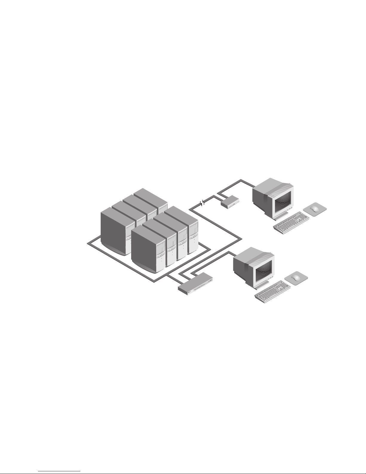
A typical confi guration is shown below.
Page 10

Rackmount Console Switch Owner’s Manual
www.hp.com/racksolutions
Page 11
www.hp.com/racksolutions
5
1. Power down all servers that will be part of your Rackmount
Console Switch system.
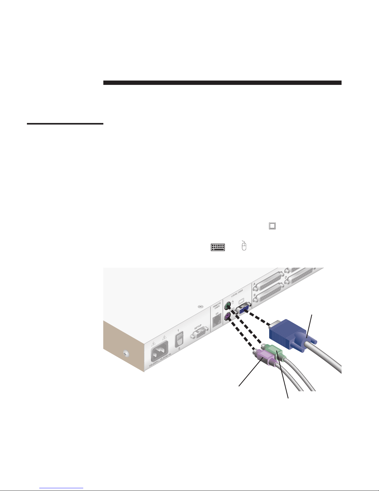
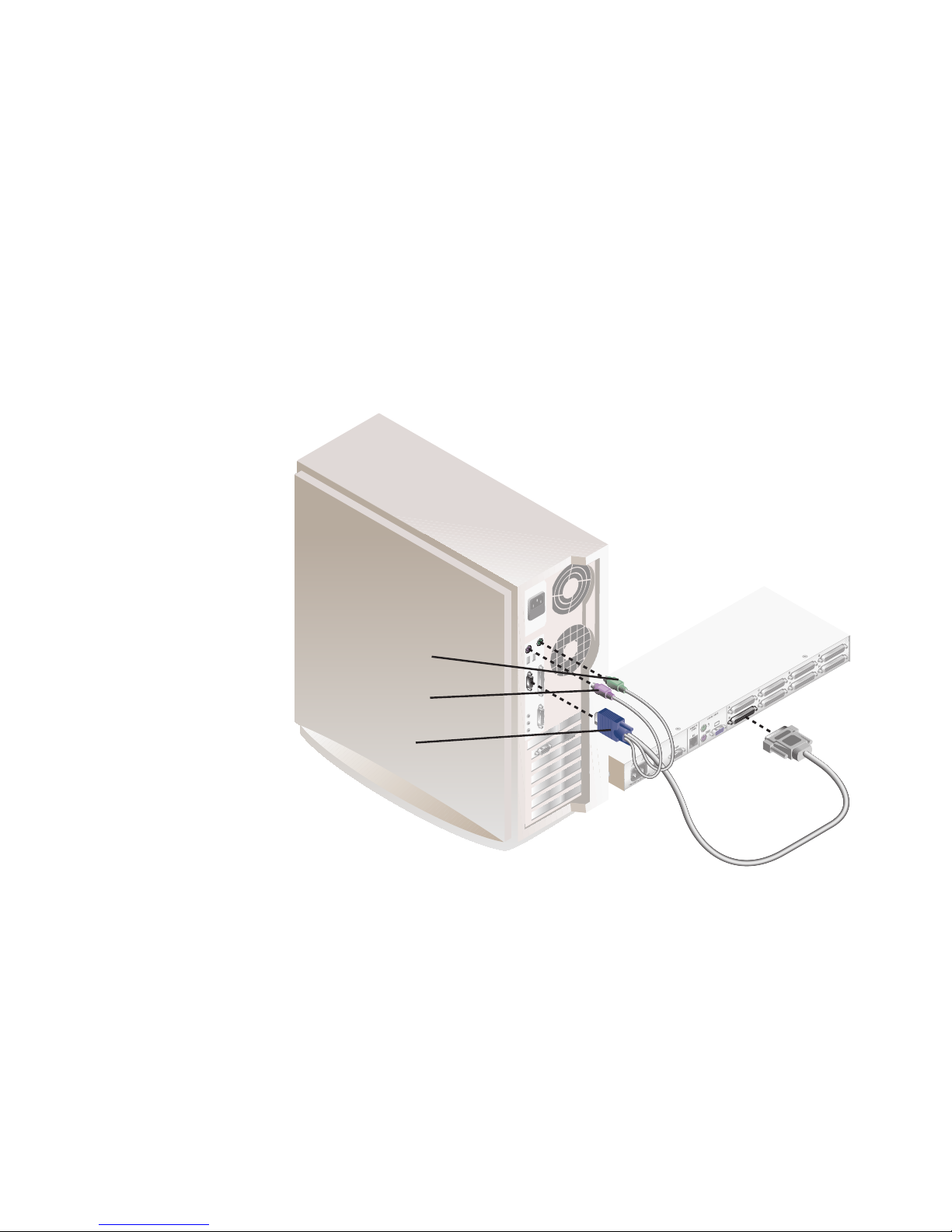
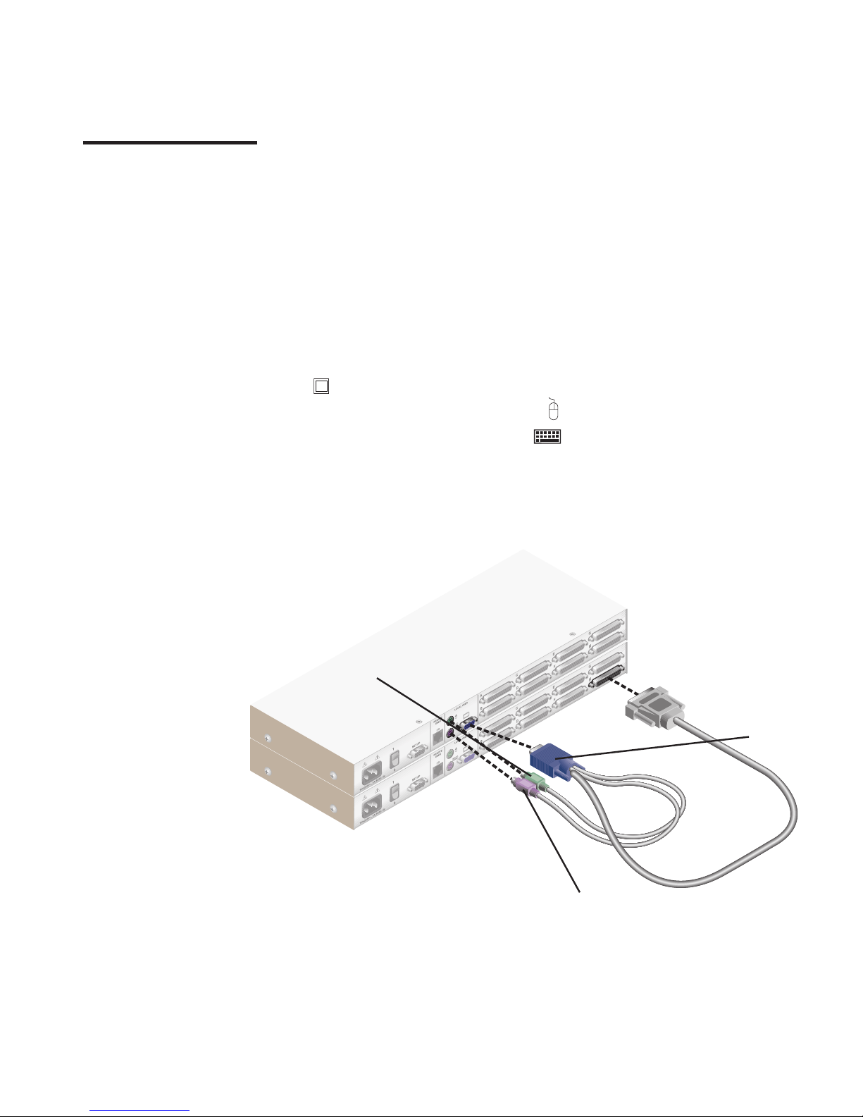
Connecting your Local User
2. Locate your PS/2 keyboard, VGA video monitor and PS/2 mouse.
3. Plug your VGA monitor cable into the port labeled
on the back of your
Rackmount Console Switch. Plug your PS/2 keyboard cable and your PS/2
mouse cable into the ports labeled
and respectively.
Installation
2
Basic Install
VGA MONITOR CABLE
PS/2 KEYBOARD CABLE
PS/2 MOUSE CABLE
Page 12
Rackmount Console Switch Owner’s Manual
www.hp.com/racksolutions
6
Connecting Servers to the Rackmount Console Switch
4. Locate your fi rst input cable. It will have a 25-pin “D” connector at one end.
Plug this cable into any numbered port on the rear of the Rackmount Console
Switch. The other end of the input cable will have three connectors: a 15-pin
“HDD” connector for video, a 6-pin miniDIN connector for a PS/2 keyboard
connection, and a 6-pin miniDIN connector for a PS/2 mouse connection. The
PS/2 mouse connector is designated by a mouse icon.
Plug these connectors into the matching ports on your server.
PS/2 KEYBOARD CABLE
PS/2 MOUSE CABLE
VGA MONITOR CABLE
(J1474A MODEL SHOWN)
5. Locate your next input cable. Repeat step 4 until all servers are properly
attached to the Rackmount Console Switch.
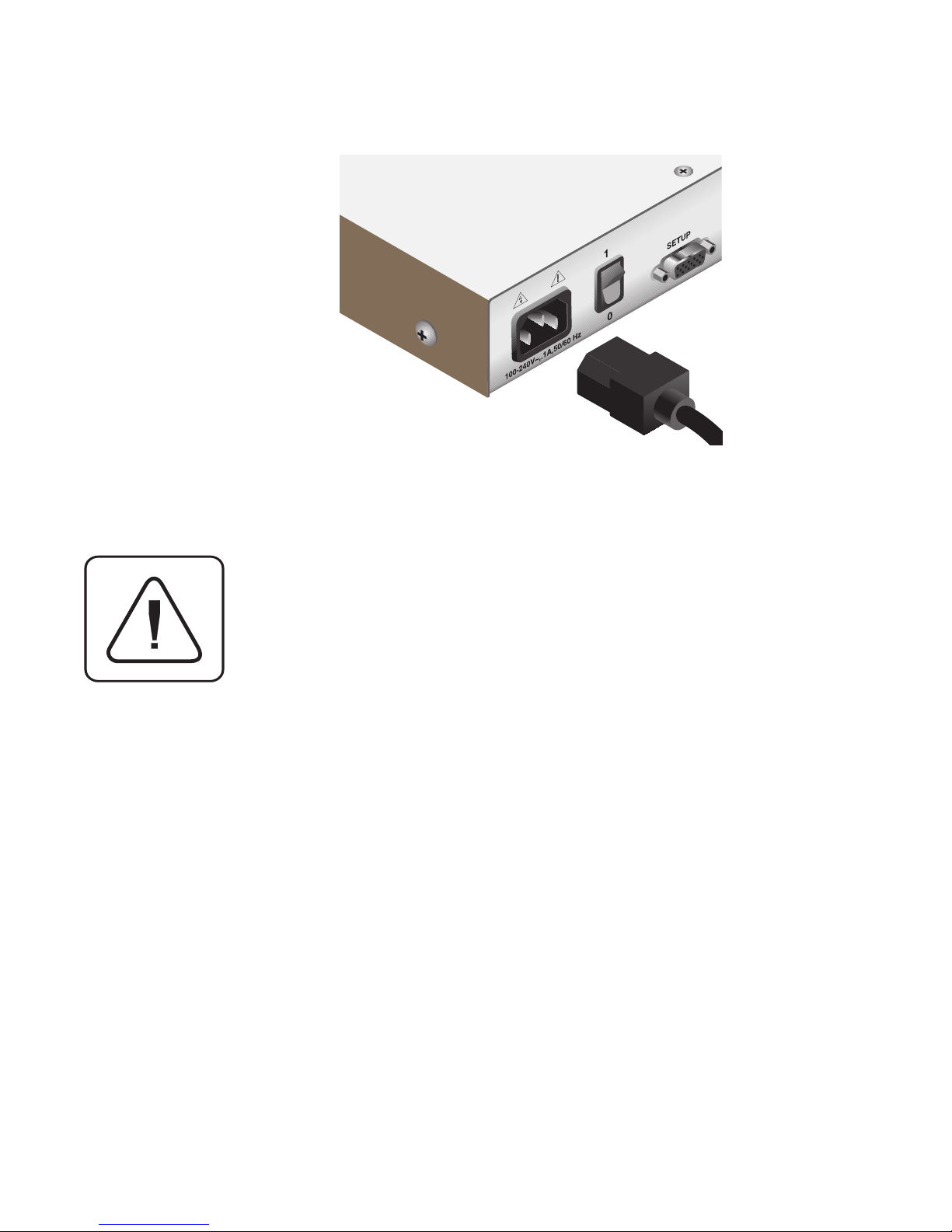
6. Locate the power cord that came with your Rackmount Console Switch. Plug
it into the IEC power connector on the switch. Make sure that the power
switch is off, then plug the other end of the power cord into an appropriate
AC outlet or Power Distribution Unit in the rack. This outlet must be near
the equipment and easily accessible to allow for unplugging prior to any
servicing of the unit.
Page 13
www.hp.com/racksolutions
7
Installation
7. Power-up your Rackmount Console Switch fi rst, then power up all
attached servers.
The Rackmount Console Switch and all attached servers should
be powered-down before servicing the unit. Always disconnect
the power cord from the wall outlet.
Page 14
Rackmount Console Switch Owner’s Manual
www.hp.com/racksolutions
8
Connecting the Optional J1475A HP Console Switch 2 User
Expansion Kit (available in North America and Latin
America only)
1. Plug a standard Category 5 Unshielded Twisted Pair cable (up to 500 feet) into
the RJ-45 style modular jack on the rear of the Rackmount Console Switch.
Make sure the Category 5 cable is wired straight through (no crossing of
wires) and that it is terminated to the EIA (TIA) 568 B standard, commonly
used for 10BaseT Ethernet.
2. Route the Category 5 cable to the location where you intend to place the
secondary monitor, keyboard and mouse.
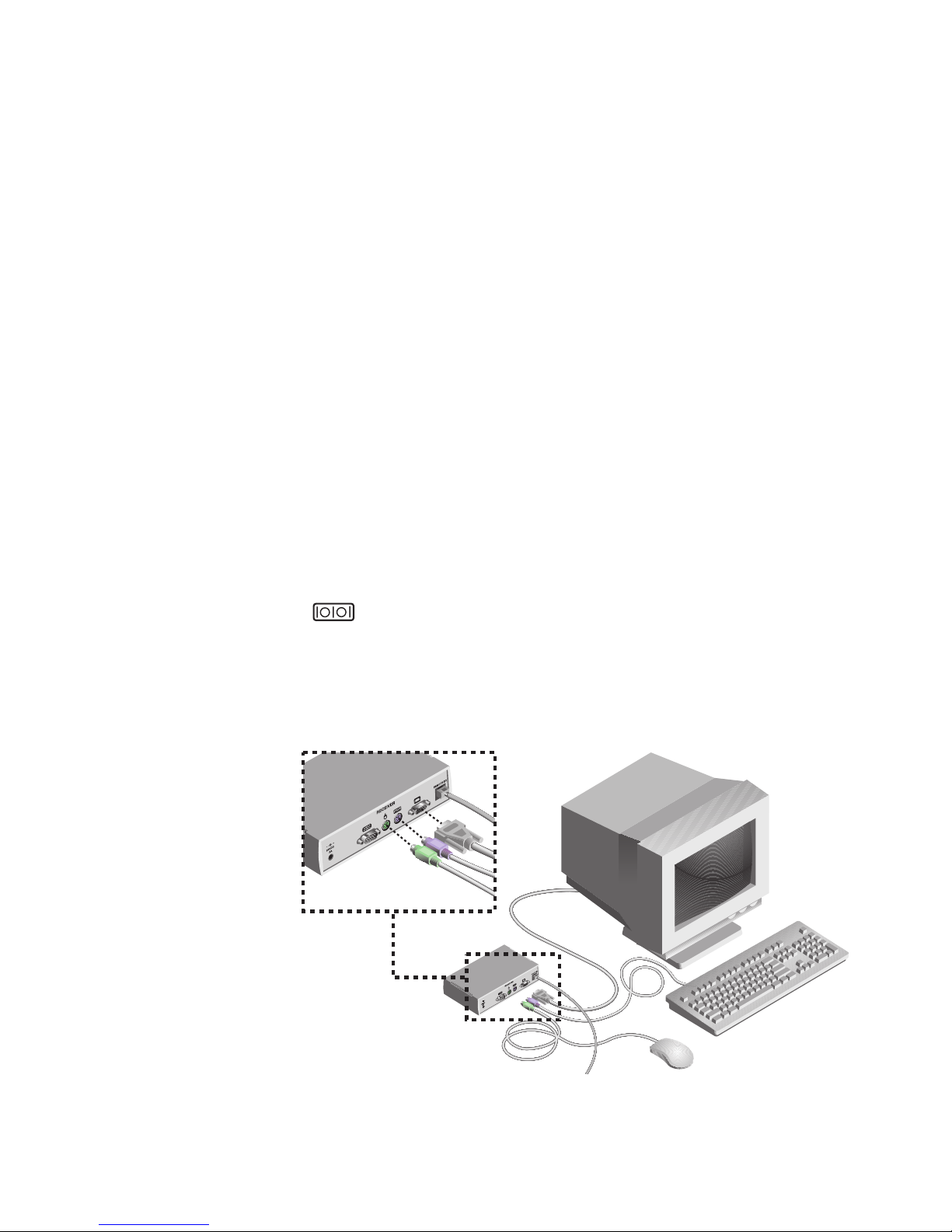
3. Place the Console Expansion Box near the monitor and connect your monitor,
keyboard and mouse to the connectors on the rear of the Expansion Box
just as you would connect them to your server. Make sure you connect your
monitor’s power supply to appropriate electrical outlets. (Please note that
the
connector on the rear of the Expansion Box is not used. Do not
Page 15

www.hp.com/racksolutions
9
connect anything to the connector on the rear of the Expansion Box.)
4. Connect the Category 5 cable to the modular jack on the rear of the
Expansion Box.
5. Connect the circular power plug from the included power supply to the
power port on the Expansion Box. Then plug the power supply into a convenient electrical outlet. (See the table on the following page for additional
power cord information.) Verify that the Expansion Box’s POWER light is
now lit.
Installation
Page 16
Rackmount Console Switch Owner’s Manual
www.hp.com/racksolutions
10
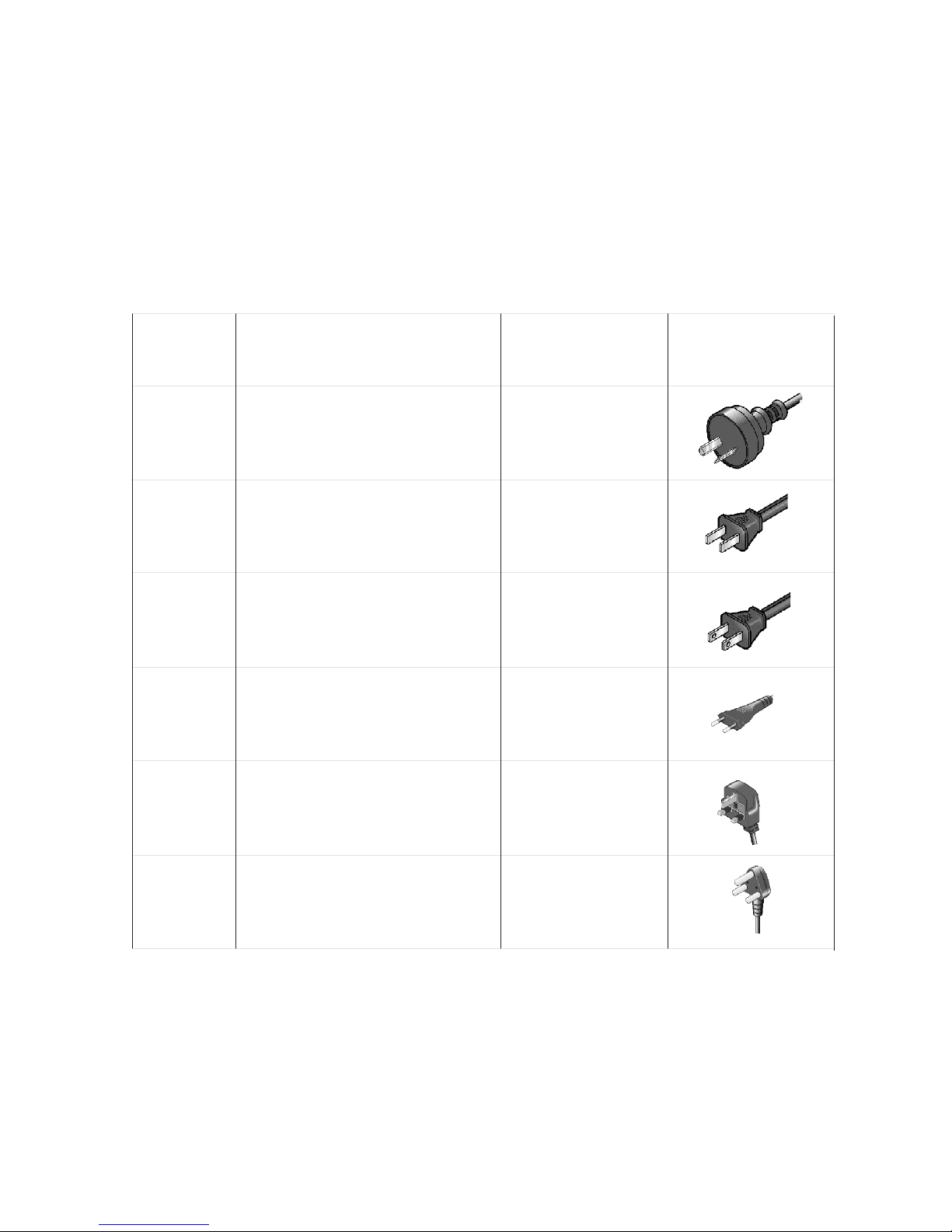
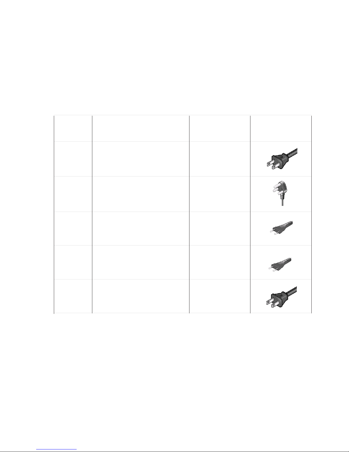
Cord Set HP
Part Number
Description
Some Countries or
Areas Where Used
Approximate
Appearance of Plug
End of Cord Set
8120-8367
RA/2 (Straight) connector: IEC 320-1
C7 (Straight) cable: 1.8 meters, Black,
250V, 2.5A
Argentina
8120-8373
8120-6312
8120-6313
8120-6314
8120-8699
PRC/3 (Straight) connector: IEC
320-1 C7 (Straight) cable: 1.8 meters,
Black, 250V, 2.5A
AS3112-2 (Straight) connector: IEC
320-1 C7 (Straight) cable: 1.8 meters,
Black, 250V, 2.5A
NEMA 1-15P (Straight) connector:
IEC 320-1 C7 (Straight) cable: 1.8
meters, Black, 125V, 2.5A
CEE 7 - XVI (Straight) connector: IEC
320-1 C7 (Straight) cable: 1.8 meters,
Black, 250V, 2.5A
BS 1363-5 (90 degree) connector:
IEC 320-1 C7 (Straight) cable: 1.8
meters, Black, 250V, 2.5A
China (PRC)
Austrailia, New
Zealand
United States, Canada,
Mexico, Taiwan
Continental Europe,
Israel
United Kingdom,
Singapore, Hong
Kong, Malaysia
Additional Power Plug Information
Page 17
www.hp.com/racksolutions
11
8120-6316
8120-6317
8120-8441
8120-8452
JIS C8303 (Straight) connector: IEC
320-1 C7 (Straight) cable: 1.8 meters,
Black, 125V, 2.5A
SABS 164 (90 degree) connector:
IEC 320-1 C7 (Straight) cable: 1.8
meters, Black, 250V, 2.5A
KSC 8305 (Straight) connector: IEC
320-1 C7 (Straight) cable: 1.8 meters,
Black, 250V, 2.5A
CEI 23-16 (Straight) connector: IEC
320-1 C7 (90 degree) cable: 1.8
meters, Black, 250V, 2.5A
Japan
South Africa, India
Korea
Chile
Cord Set HP
Part Number
Description
Some Countries
Where Used
Approximate
Appearance of Plug
End of Cord Set
8121-0664
NEMA 1-15P (Straight) connector: IEC
320-1 C7 (Straight) cable: 1.8 meters,
Black, 250V, 2.5A
Brazil, Thailand
Additional Power Plug Information Continued
Installation
Page 18
Rackmount Console Switch Owner’s Manual
www.hp.com/racksolutions
12
Attaching Multiple Rackmount Console Switches
1. Follow steps 1-3 of the Basic Install section for each cascaded unit.
2. Plug the 25-pin “D” connector of your input cable into any available server port
on the rear of your base Rackmount Console Switch.
3. Plug the 15-pin video connector on the other end of the cable into the port
labeled
on your fi rst cascading switch. Plug the PS/2 mouse connector,
designated by a mouse icon, into the
port. Plug the remaining 6-pin
miniDIN keyboard connector into the
port.
4. Repeat steps 4-7 in the section ‘Connecting Servers to the Rackmount Console
Switch’ for each attached server.
Advanced Install
CASCADING
UNIT
BASE UNIT
PS/2 KEYBOARD CONNECTOR
PS/2 MOUSE
CONNECTOR
VIDEO
CONNECTOR
(J1474A MODELS SHOWN)
Page 19

www.hp.com/racksolutions
13
Basic Operations
3
The following notational conventions appear throughout this chapter to illustrate
commands for operating the Rackmount Console Switch. Whenever you see one
of the symbols listed on the left side of the table, substitute the corresponding
steps or values listed on the right.
Keyboard Control
Convention Key Sequence or Value
Enter Command Mode:
<CM> 1. Press and hold down the ‘Num Lock’ key.
2. Press and release the minus (-) key on the numeric keypad.
3. Release the ‘Num Lock’ key.
Note: For alternate hot-key sequences, see ‘System Control &
Maintenance’ later in this chapter.
<Enter> Press the ‘Enter’ or ‘Return’ key. The <Enter> command is used to
execute an instruction and exit from Command Mode.
Addr The numbers on your Rackmount Console Switch are your servers'
addresses. Enter the number for the server you're selecting. For
cascaded systems, enter the port address on the base unit where
the second switch is attached, then a period (.) followed by the
address of the server in your cascaded unit.
Example: A switch is cascaded from port 2 of your base unit.
To access the server at port 3 of this second (cascaded) unit,
enter 2.3.
<ESC> Press the ‘Escape’ key. The <ESC> command is used to exit
Command Mode without executing an instruction.
Regarding OSD on-screen menu commands, the words ‘choose’ and ‘select’
indicate that a users should highlight the relevant command and press the
enter key.
Page 20
Rackmount Console Switch Owner’s Manual
www.hp.com/racksolutions
14
Key Sequence Action
<CM>Addr<Enter> Selects an active port via keyboard.
Keyboard
Switching
One of the ways to change the active port in a non-secured Rackmount Console
Switch system is by entering a short sequence of keystrokes on the keyboard. This
is called keyboard, or hot-key, switching.
Note: Hot-key switching is only available in the default non-secure state. For more
information on secure versus non-secure operation, see the ‘Administrator
Functions’ section of Chapter 4.
The fi rst set of keystrokes places your system in Command Mode. A blue window
with a line for commands will appear. As long as you are operating in Command
Mode, whatever you type will be interpreted as port switch commands until
the Enter or the ESC key is pressed to terminate Command Mode. None of
the keystrokes entered will be forwarded to the attached server until you exit
Command Mode.
Next, enter the address (Addr) for the port you wish to select.
Press Enter to accept the new port. The following command line shows the proper
format used to switch your active port via keyboard.
Below is a sample of a keyboard switching session, with an accompanying
explanation for each step.
Key Sequence Action
1. <CM>4<Enter> Selects Port 4 on the base unit as the active port.
2. <CM>3.2<Enter> Selects the switch attached to Port 3 on the base unit, then
selects Port 2 on the cascaded unit.
3. <CM>1<Enter> Selects Port 1 on the base unit as the active port.
4. <CM>2.1<ESC> Exit Command Mode. The instruction is not executed. Port
1 is still the active port.
Page 21
www.hp.com/racksolutions
15
Basic Operations
System Control &
Maintenance
Key Sequence Action
<CM>Kn<Enter> Sets the keyboard scan set where n is a scan set number 1-3.
<CM>MR<Enter> If you hot-plug your mouse cable, you may experience a loss of
mouse signal. Use this command to restore the signal if you are
using a server with a standard PS/2 mouse driver.
<CM>MW<Enter> If you hot-plug your mouse cable, you may experience a loss of mouse
signal. Use this command to restore the signal if you are using a server
with a Microsoft IntelliMouse or other wheel mouse driver.
<CM>AV<Enter> Displays the current fi rmware version of your switch.
<CM>SG<Enter> Enables the scan Go command (By address only)
<CM>SH<Enter> Enables the scan Halt command
<CM>M+<Enter> Enables mouse suspension of scanning
<CM>M-<Enter> Disables mouse suspension of scanning
<CM>H1<Enter> Changes the hot-key sequence to the default: (NumLock, -)
<CM>H2<Enter> Changes the hot-key sequence to the 1st alternate: (NumLock, *)
<CM>H3<Enter> Changes the hot-key sequence to the 2nd alternate: (CTRL, ~)
<CM>OSD0<Enter> Disables the OSD Sequence
<CM>OSD1<Enter> Changes the OSD sequence to the default: (CTRL, CTRL)
<CM>OSD2<Enter> Changes the OSD sequence to the 1st alternate: (Alt, Alt)
<CM>OSD3<Enter> Changes the OSD sequence to the 2nd alternate: (Shift, Shift)
<CM>ZM<Enter> Use this command to resynchronize the mouse after a device
or server hot-plug. Repeat, if necessary, until synchronization is
re-established.
Note: Using this command while the mouse is operating cor-
rectly will cause the mouse to lose sync.
The following commands are used for system control and maintenance. Enter the
command sequences to perform the actions described in the table below.
Page 22

Rackmount Console Switch Owner’s Manual
www.hp.com/racksolutions
Page 23

www.hp.com/racksolutions
17
4
Activating OSD
On-Screen Display
Operations
Activate on-screen display (OSD) by pressing either of the keyboard Ctrl (control)keys
twice within one second. Refer to the section ‘System Control & Maintenance’ in
the previous chapter for alternate sequences. In nonsecure mode, this brings up
the main OSD Window, “Administrator Port List”.
In secure mode, activating OSD will bring up the “User Login” window. Type
in your user name and press Enter. The system administrator should login as
“Admin”, “Root” or “Administrator”. Type your password and press Enter. This
will bring up your “Port List”. If there is no keyboard activity, the login window
will timeout after fi ve minutes and go blank to allow the monitor’s energy saver to
execute. Activate on-screen display to restore the login prompt.
Note: All Rackmount Console Switches ship in the default non-secure state.
For more information on secure versus non-secure operation, see the
section ‘Administrator Functions’.
Page 24

Rackmount Console Switch Owner’s Manual
www.hp.com/racksolutions
18
This window lists all named ports in your Rackmount Console Switch system.
They will be listed alphabetically by name with their port addresses and access
status beside them. Beside the address there will be a small circle. If the circle
is fi lled, the server in question is powered on. When in secure mode, only the
ports that are accessible to the logged in user will be listed. (See the section
‘Administrator Functions’ for more information.)
THE MAIN OSD WINDOW
The OSD Window
Use your up and down arrow keys and the page up and down keys to select a port.
Move immediately to the top or bottom of the list with the home and end keys.
Press a letter while in the main OSD Window, and the Highlight Bar moves
to the fi rst port name beginning with that letter. Press the letter repeatedly
to scroll through all ports that begin with that letter from top to bottom.
Press Enter to make the switch. To exit the OSD Window without changing
ports, press Esc.
To manually logout when in secure mode, press F10.
Administrator Channel List
Name Access
Kyle A
Address
V K o
F10-Logout
Kyle A V K o
John B V o
Pam C V K o
Gilbert D V o
Hewlett Packard Console Switch
Page 25

www.hp.com/racksolutions
19
Games
Hewlett Packard Console Switch
Administrator Command Menu
Add Port
Edit Port
Delete Port
Administrative Functions
Scanning is OFF
Reset Standard Mse/Kbd
Reset Wheel Mse/Kbd
Version Information
ENTER = activate
ESC = exit
Once you have activated the main OSD Window, you can open the Command
Menu by pressing either of the Ctrl keys twice.
The Command Menu options are selected in the same manner as ports in the
OSD Window. Scroll the Highlight Bar up and down and press Enter when
your selection is highlighted.
The Command
Menu
THE COMMAND MENU
On-Screen Display Operations
If you are operating in non-secure mode or are the system administrator, you’ll
have several options that are not in the User level Command Menu. Add Port, Edit
Port, Delete Port and Administrator Functions are covered in separate sections in
this chapter. Scanning is covered in Chapter 6.
If you experience a loss of mouse signal while using the Rackmount Console
Switch, select the ‘Reset Standard Mouse/Keyboard’ option from this menu for
a server with a standard mouse driver or ‘Reset Wheel Mouse/Keyboard’ if you are
using a server with a Microsoft IntelliMouse or other wheel mouse driver. This will
reset and in most cases restore your mouse signal. These commands are equivalent
to the <CM>MR<Enter> and <CM>MW<Enter> keyboard commands listed in
the ‘System Control & Maintenance’ section of this manual.
Choose the option ‘Version Information’ to display on your monitor the current
version level of your Rackmount Console Switch fi rmware. Press the Esc key to
clear this information from your screen.
Page 26

Rackmount Console Switch Owner’s Manual
www.hp.com/racksolutions
20
Basic Port Maintenance is performed from the Administrator Command Menu,
and is available if you are operating in non-secure mode or if you are the system
administrator. Here you can add, delete or edit ports.
Basic Port
Maintenance
THE ADD PORT WINDOW
Hewlett Packard Console Switch
Add Port
ENTER = save ESC = exit
Name
Address
ID Dwell Time 5
Scan Dwell Time 5
ID Setup
Save Changes
Adding Ports
1. Select ‘Add Port’ from the Administrator Command Menu or press the
Insert key. Type in a new port name, up to 14 characters long, and
press Enter.
2. Type in the address for the server you are naming and press Enter. Please
note that the address cannot be longer than two digits.
3. Enter the dwell time for the ID Window and press Enter.
4. Enter the dwell time for scanning and press Enter.
5. After selecting “ID Setup”, use the arrow keys to position the ID window to
where you would like it to appear when this port is selected. Then press Enter.
(For further information see ‘The ID Window’ later in this chapter.)
Press Esc at any point to exit this operation without adding the port.
Page 27

www.hp.com/racksolutions
21
Editing Port Names and Addresses
1. Highlight the port you wish to change in the main OSD Window.
2. Press the Ctrl key twice to access the Command Menu or press the F2 key once.
(If you press F2 skip Step 3)
3. Select ‘Edit Port’ from the Command Menu.
4. Enter the new port name, address, ID Dwell time and Scan Dwell time. Press
Enter to accept.
5. After selecting “ID Setup”, use the arrow keys, position the ID window to where
you would like it to appear when this port is selected. Then press Enter. (For
further information see ‘The ID Window’ later in this chapter.)
6. Select “Save Changes” and press Enter to accept.
Press Esc at any point to exit this operation without saving the changes.
Deleting an Existing Port
1. Highlight the port you wish to delete in the main OSD Window.
2. Press the Ctrl key twice to access the Command Menu or simply press the
DELETE key. (If you press DELETE skip Step 3)
3. Choose the ‘Delete Port’ option.
4. Type Y or N at the prompt to confi rm the deletion and press Enter.
On-Screen Display Operations
Page 28
Rackmount Console Switch Owner’s Manual
www.hp.com/racksolutions
22
Operation Procedure
Move the ID Window Use the arrow keys or mouse to move the ID
Window's position on the monitor. (Hold down
the SHIFT key to move faster.) If the window fl ickers but does not move, continue tapping the arrow
keys until it moves back into range.
Change window background color Press the <PAGE UP> key to cycle through the
available window background colors.
Change text color Press the <PAGE DOWN> key to cycle through
the available text colors.
Change window length Use the (+) and (-) keys to change the length of
the ID Window.
Change window size Press SPACE to toggle between large and small.
ID Window Help Press F1
The ID Window appears when you change ports and displays the name of the
selected port. This window can be individually confi gured for each port in your
system. The characteristics of the ID Window can be changed from the Edit Port
Menu. This option is only available if you are operating in non-secure mode or if
you are the system administrator.
Changing the Size, Color and Position of the ID Window
1. Highlight the port you wish to change in the main OSD Window.
2. From the main OSD Window, press the Ctrl key twice to access the Command
Menu or press F3. (If you press F3 skip Step 3)
3. Select ‘Edit Port’ from the Command Menu.
4. Choose the option ‘ID Setup.’
Follow the procedures outlined in the table below to change the size, color or
position of your ID Window.
The ID Window
Page 29

www.hp.com/racksolutions
23
Setting the ID Window Dwell Time
This menu selection lets you set the time that the ID Window remains on screen
after a port switch. Each port can be confi gured independently. The default
time is set for fi ve seconds.
1. Highlight the port you wish to change in the main OSD Window.
2. From the main OSD Window, press the Ctrl key twice to access the Administrator
Command Menu.
3. Select ‘Edit Port’ from the Command Menu.
4. Choose the option ‘ID Dwell Time’.
5. Enter a number between 0-255 seconds. Entering 0 disables the ID Window.
Entering 255 allows the ID Window to stay on screen the entire time
the port is active.
5. Press Enter to accept the changes or press Esc to exit the menu without
saving the changes.
On-Screen Display Operations
Page 30

Rackmount Console Switch Owner’s Manual
www.hp.com/racksolutions
24
The Administrator Functions Menu is accessed from the Administrator Commands
Menu. Here, you can setup the administrator and user accounts and utilize the
Rackmount Console Switch’s FLASH upgrade feature.
Differences between Secure and Non-Secure Operating Modes
Administrator Account
Setting up an administrator account with a password places your system in secure
mode. Non-secure systems do not use passwords. To return your system to the
default of non-secure mode, simply delete the administrator password. When
the administrator password is enabled, user passwords must also be entered or
the switch will not be completely secure. The default for users is no password.
Simply press Enter at the prompt.
If you confi gure an administrator password from this menu, your system will then
be in secure mode. A lock symbol will appear to the right of the menu headings
to indicate secure operation.
Logout Capability
You have the option of automatically logging out of the system after an administrator
defi ned period of inactivity. Timeout values can be set from 0 to 60 minutes.
(Default is fi ve minutes). A value of 0 keeps the user logged in continuously.
When the timeout is reached, the current port is deselected and the display goes
to the login prompt. Users must login again to access system servers. This option
is only available in secure mode.
Multiple User Logins
You can create up to four user logins in addition to the system administrator. Use
these logins to confi gure and control server access for every type of system user.
The administrator has full access privileges; additional users can have viewing
or viewing with keyboard and mouse control capability for each attached server.
This option is only available in secure mode.
Administrator
Functions
Page 31

www.hp.com/racksolutions
25
On-Screen Display Operations
Creating the Administrator Account
1. Press the Ctrl key twice to access the Command Menu.
2. Select ‘Administrator Functions’ from the Command Menu.
3. Select ‘Setup Administrator’ from the Administrator Menu.
4. Type your password and press Enter. (The password is not case sensitive.)
5. Repeat entry of the password for confi rmation.
6. Enter the number of minutes you wish to pass without keyboard/mouse
activity before the administrator is automatically logged out of the system.
Entering a 0 keeps the administrator logged on continuously; 60 is the
maximum setting.
CAUTION: Security is enabled once the password has been created.
Store a copy of your password in a safe place.
You should now see the option ‘F10 - Logout’ at the bottom of your main OSD
Window and a lock symbol to the right of the menu headings.
Setting Up Additional Users
1. Press the Ctrl key twice to access the Command Menu.
2. Select ‘Administrator Functions’ from the Command Menu.
3. Select ‘Setup User 1’ from the Administrator Menu.
4. Choose the ‘Name’ heading and enter the name for this user.
5. Choose the ‘Password’ heading and enter the password and confi rm it for this
user. (Passwords are not case sensitive.)
6. Choose the ‘Logout Time’ heading. Enter a value in minutes for this user’s
logout time. A value of 0 keeps the user logged on continuously; 60 is the
maximum setting. The default is set for 5 minutes.
Page 32

Rackmount Console Switch Owner’s Manual
www.hp.com/racksolutions
26
7. Choose the ‘Access Setup’ heading. Here, you will see a listing of all attached
servers in the port list. For each server, choose a level of access for this user by
selecting one of the function keys listed on the screen: F5 for no access, F6 for
video only or F7 for video and keyboard/mouse capability. The default is set
for full access. All changes go into effect as soon as they are made. Press Enter
when you have completed your confi guration.
8. Press Enter to accept your selections and repeat steps 3-7 for each
remaining user.
FLASH Upgrades
FLASH Upgrading allows you to change the code that runs your Rackmount
Console Switch. This lets you enhance the features of your switch and keep it
current with the latest improvements in KVM switching. For more information,
see Appendix B.
Page 33

www.hp.com/racksolutions
27
If you have purchased the optional Console Switch 2 User Expansion Kit, you
can utilize advanced features that go beyond those available in the standard
Rackmount Console Switch. Primarily, the kit provides for a remote user that
may be located up to 500 feet away from the switch. The remote user has all the
capabilities of the local user and can access any server attached to the Rackmount
Console Switch just as if he were sitting in front of it.
Within the base unit, there are two ways to utilize the multiuser capabilities
of the Rackmount Console Switch. You can access servers independently or
share access with the other user.
Independent Access
As long as both users are trying to access servers attached to the base Rackmount
Console Switch, they may access any of them independently at the same time. In
the diagram below, either user may access any attached
server at any time. They may also share access to any attached server.
5
Multiuser
Operation
Console Switch 2 User
Expansion Kit (Optional)
(available in North America and Latin America only)
Page 34

Rackmount Console Switch Owner’s Manual
www.hp.com/racksolutions
28
Multi chassis operation involves independent access only.
Both users can simultaneously and independently access any server attached
to the base Rackmount Console Switch unit. Similarly, independent access is
possible across expansion units as long as each user is accessing a different
expansion unit.
Multi Chassis
Operation
Shared Access
If both users need to access the same server in the base unit, they can ‘share’ access
to it through the Rackmount Console Switch. Sharing means that both consoles
can view a server port at the same time, but only one can enter data through
the keyboard or mouse at any given moment. As soon as the active console
stops all keyboard and mouse activity, the other console can take control
of the server.
For information on access across multiple Rackmount Console Switch units, see
‘Multi Chassis Operation’ below.
Page 35

www.hp.com/racksolutions
29
For example, in the confi guration below, two users can access nine servers through
three Rackmount Console Switch units.
BASE UNIT
UNIT C
UNIT B
3
2
1
Example
Advanced Operation
3
2
1
3
2
1
Independent Access Options
1) Both users can independently access the three servers attached to the
base unit at any time.
2) Both users can independently access any server in a different Rackmount
Console Switch unit at any time.
If one user is working on Port 1 of the base unit, the other user can be
independently using servers 2 or 3 of the base unit, or any server attached
to units B or C.
If one user is working on Port 2 of unit B, the other user can be independently using
any server attached to the base unit or Unit C. This user cannot independently
access any server attached to Unit B until the fi rst user connects to a server
attached to a different Rackmount Console Switch unit.
Page 36

Rackmount Console Switch Owner’s Manual
www.hp.com/racksolutions
Page 37

www.hp.com/racksolutions
31
6
Choosing a
Scanning Method
The Rackmount Console Switch's scanning feature allows you to automatically
monitor, or scan, your server ports without intervention. When keyboard
activity is detected, scanning is suspended until all keyboard activity stops.
Scanning then resumes with the next port in sequence. The length of time
each port remains on the screen, or dwell time, is confi gurable and can be
changed at any time.
There are three ways to scan through the ports in your Rackmount Console Switch
system: by name, by address or by list. Please note that the switch only scans
the servers that are in your OSD list.
Scanning by name allows you to scan ports in alphanumeric order according to
the port list in the main OSD Window.
Scanning by address allows you to view each of your active ports in port
number order.
Scanning by list allows you to create a customized scanning order for the
switch to follow. Any active port in the system can be scanned in any order,
as many times as desired.
With all scan methods, you can adjust the dwell time for each port or omit a port
from the scan sequence completely.
Choose whichever method is most appropriate for your confi guration.
Port Scanning
Page 38

Rackmount Console Switch Owner’s Manual
www.hp.com/racksolutions
32
Key Sequence Action
<CM>SG<Enter> Enables the scan Go command. (By Address Only)
<CM>SH<Enter> Enables the scan Halt command.
From the OSD menu.
1. From the main OSD Window, press the Ctrl key twice to access the Com-
mand Menu.
2. Toggle ‘Scanning is OFF’, ‘Scan by Name’, ‘Scan by Address’ or ‘Scan by List’
from the menu. This is a toggle option - only one scanning option will show
on the menu at any one time.
3. Press Enter.
By keyboard hot-key sequence
The following key sequences control scanning.
Turning Scanning
On and Off
Page 39

www.hp.com/racksolutions
33
Appendices
7
A: Specifi cations
Mechanical
Height: 1.7" (4.5 cm)
Width: 17.2" (43.7 cm)
Depth: 6.5" (16.51 cm)
Weight: 4.8 lbs (1.91 kg)
Environmental/
Operating Temperature: 41° (5°C) to 104° (40°C)
Power Storage Temperature: -4° (-20°C) to 122° (50°C)
Operating Voltage: 100 - 240 VAC
Power Frequency: 50 - 60 Hz
Supported Hardware
Computer: IBM PC/AT, PS/2 and 100% compatibles
Video Modes: VGA, SVGA
Maximum Resolution: 1600 x 1200 @ 72 Hz
Peripherals: PS/2 keyboard, PS/2 mouse, IntelliMouse (PS/2
only), IBM Scrollpoint, Logitech Mouseman +, Logitech Marble
Plus, Logitech Marble FX and Kensington Expert mouse.
Regulatory
UL 1950, CSA C22.2 No. 950, EN60950
Standards
FCC part 15A, EN55022, EN50082
Page 40

Rackmount Console Switch Owner’s Manual
www.hp.com/racksolutions
34
B: FLASH
Upgrading
A Rev Code B Rev Code
Hardware/Software Requirements:
• Rackmount console switch
• Serial host system (i.e. laptop or desktop computer)
• 9-pin straight pass non-null modem serial cable (RS-232)
• HyperTerminal or other terminal emulation software (HyperTerminal is
included with MS Windows 95, 98, NT, and 2000)
• FLASH code fi le (downloaded fi rmware revision)
To upgrade the FLASH code on your Rackmount Console Switch, you will fi rst need
to determine if your unit is running A or B revision code. To do this, select the menu
choice ‘Version Information’ from the Command menu. The fi rst letter of the
revision code displayed will determine if your unit uses the A or B code.
Administrator Command Menu
Add Port
Edit Port
Delete Port
Administrative Functions
Scanning is OFF
Reset Standard Mse/Kbd
Reset Wheel Mse/Kbd
Version Information
ENTER = activate
ESC = exit
Hewlett Packard Console Switch
Version Information
Firmware Version A06
Press ESC to exit
Hewlett Packard Console Switch
Version Information
Firmware Version B10
Press ESC to exit
Hewlett Packard Console Switch
You will next need to obtain the latest FLASH firmware revision from
Hewlett-Packard. It is available through the Hewlett-Packard web site at
www.hp.com/go/enclosures.
Page 41

www.hp.com/racksolutions
35
Appendices
Instructions for Console Switches with Revision Code A
1. Connect the 9-pin serial cable between the Rackmount Console Switch
and the serial host system.
2. From your server, activate the OSD menu on your Rackmount Console Switch
by tapping the Control key twice. Enter Control twice more to activate the
Administrator Commands screen and then select Administrator Functions.
Administrator Command Menu
Add Port
Edit Port
Delete Port
Administrative Functions
Scanning is OFF
Reset Standard Mse/Kbd
Reset Wheel Mse/Kbd
Version Information
ENTER = activate
ESC = exit
Hewlett Packard Console Switch
3. Use the down arrow key to highlight the menu selection for FLASH Upgrade,
then press Enter.
Administrator Functions
Setup Administrator
Setup USER1
Setup USER2
Setup USER3
Setup USER4
Flash Upgrade
ENTER = activate
ESC = exit
Hewlett Packard Console Switch
4. A menu screem will appear and ask if you wish to continue. You must type
‘Yes’ before preceding. Once you have done this, the switch will go into
standby mode and wait for data from the server. (Note: The keyboard, video
and mouse are disabled during FLASH upgrade.)
Flash Upgrade Confirmation
Type YES and press ENTER to
perform a Flash Upgrade
= = = WARNING = = =
During this process the
keyboard, video and mouse are
disabled until either the Flash
Upgrade is done or 3 minutes
time elapses
yes
Hewlett Packard Console Switch
Page 42

Rackmount Console Switch Owner’s Manual
www.hp.com/racksolutions
36
5. Using HyperTerminal to upgrade the FLASH code*
a. From your serial host system start HyperTerminal by clicking the
Start button, then selecting Programs, Accessories, and HyperTerminal
in Windows 95, 98, or NT.
b. Choose an appropriate name (FLASH) and click OK. (you do not have
to select an icon)
c. A pop-up window will appear, select an available port and click OK.
d. A new pop-up window will appear. Change to the following parameters:
Bits per second 38,400
Data Bits 8
Parity None
Stop Bits 1
Flow Control None
e. A blank screen will appear. From the top bar, select Transfer then Send
Text File.
f. Change File Type to ‘All Files’ and fi nd the downloaded fi rmware revision
on your hard drive and click OK.
The Rackmount Console Switch will automatically check the upgrade and make
sure that it is valid. If the switch detects an error, it will abort the upgrade and
retain the original OSD fi rmware. Otherwise, it will return the message, “Flash
Upgrade Successful”. If the fi le read does not validate, you will be prompted
to re-transfer your fi le.
* Step 5 processes are for HyperTerminal only. Other emulation packages may
have different steps
.
Page 43

www.hp.com/racksolutions
37
Instructions for Console Switches with Revision Code B
1. Connect the 9-pin serial cable between the Rackmount Console Switch
and the serial host system.
2. From your server, activate the OSD menu on your Rackmount Console Switch
by tapping the Control key twice. Enter Control twice more to activate the
Administrator Commands screen and then select Administrator Functions.
Administrator Command Menu
Add Port
Edit Port
Delete Port
Administrative Functions
Scanning is OFF
Reset Standard Mse/Kbd
Reset Wheel Mse/Kbd
Version Information
ENTER = activate
ESC = exit
Hewlett Packard Console Switch
3. Use the down arrow key to highlight the menu selection for FLASH Upgrade,
then press Enter.
Administrator Functions
Setup Administrator
Setup USER1
Setup USER2
Setup USER3
Setup USER4
Flash Upgrade
ENTER = activate
ESC = exit
Hewlett Packard Console Switch
4. A menu screem will appear and ask if you wish to continue. You must type
‘Yes’ before preceding. Once you have done this, the switch will go into
standby mode and wait for data from the server. (Note: The keyboard, video
and mouse are disabled during FLASH upgrade.)
Flash Upgrade Confirmation
Type YES and press ENTER to
perform a Flash Upgrade
= = = WARNING = = =
During this process the
keyboard, video and mouse are
disabled until either the Flash
Upgrade is done or 3 minutes
time elapses
yes
Hewlett Packard Console Switch
Page 44

Rackmount Console Switch Owner’s Manual
www.hp.com/racksolutions
38
5. Using HyperTerminal to upgrade the FLASH code*
a. From your serial host system, start HyperTerminal by clicking the
Start button, then selecting Programs, Accessories, and HyperTerminal
in Windows 95, 98, or NT.
b. Choose an appropriate name (FLASH) and click OK. (you do not have
to select an icon)
c. A pop-up window will appear, select an available port and click OK.
d. A new pop-up window will appear. Change to the following parameters:
Bits per second 38,400
Data Bits 8
Parity None
Stop Bits 1
Flow Control None
e. A blank screen will appear. From the top bar, select Transfer then Send
File. Browse for the downloaded fi rmware revision and highlight it.
Click Open to dowload this fi le. On the same screen, change the protocol
to XMODEM. Click Send to begin the download.
6. The Rackmount Console Switch will automatically check the upgrade and
make sure that it is valid. If the switch detects an error, it will abort the
upgrade and retain the original OSD fi rmware. Otherwise, it will return the
message, “Flash Upgrade Successful”. If the fi le read does not validate, you
will be prompted to re-transfer your fi le.
* Step 5 processes are for HyperTerminal only. Other emulation packages may
have different steps.
Page 45

www.hp.com/racksolutions
39
C: Troubleshooting
Our Technical Support staff is ready to assist you with any installation or hardware
problems you encounter with your Rackmount Console Switch. If a problem
should develop, follow the steps below:
1. Check the troubleshooting tables to see if the problem can be resolved by
following the procedures outlined.
2. If you are unable to fi nd a resolution, fi ll out the Problem Report in Appendix
D completely.
3. Check the Hewlett Packard web site at www.hp.com/go/enclosures for the
HP support service phone number nearest you. Have your Problem Report
with you when you call. To expedite assistance, have this manual with you
when you call, along with a copy of your invoice giving the date purchased
and other identifying data.
Page 46

Rackmount Console Switch Owner’s Manual
www.hp.com/racksolutions
40
Symptom Action
Unable to hot-key switch to Check the power indicator on the OSD screen to ensure
a port that the system in question is powered.
Verify that you are not in secure mode. (No lock symbol
on OSD screen.)
Verify that you are in hot-key mode. Press escape and
try going into command mode again. If the problem
persists, contact Technical Support.
No video Verify that the video cable between the server and the
switch is correctly connected. Verify that the monitor
cable is correctly connected to the switch.
Power down the server. Connect the monitor directly to
the server and power up again. If the monitor operates
correctly direct to the server, contact Technical Support.
If it does not, try another monitor.
Mouse jumps or “hugs” screen If the mouse has been hot-plugged while running in
Windows, you may need to close and restart Windows.
If the mouse still does not function, try the mouse resyn-
chronization command <ZM>. (For instructions on command mode, see 'Basic Operations'.) If the problem persists, contact Technical Support.
Appendices
Page 47

www.hp.com/racksolutions
41
Symptom Action
Mouse is inoperable on one If the mouse is inoperable on a port, try the mouse
server port reset command <MR> or <MW> with that server selected.
(For instructions on command mode, see ‘Basic Operations’.)
Verify that the cables from the server to the
switch are connected properly.
Make sure that you have keyboard/mouse privileges for
that port.
Verify that the mouse driver and application are confi gured
properly for mouse support.
Verify that the server works properly with a mouse con-
nected directly to it. If the problem persists, contact Technical Support.
Mouse is inoperable on all Verify that the mouse is plugged into the correct PS/2
server ports port on the back of the switch.
Try the mouse reset command <MR> or try the ‘Reset stan-
dard mouse/keyboard’ command from the OSD Command
Menu for servers using PS/2 mice. Use <MW> or ‘Reset
wheel mouse’ for servers using the Microsoft IntelliMouse.
(For instructions on command mode, see the ‘Basic Operations’ chapter.)
Verify that the mouse works when connected directly to a
server.
Cycle power to the switch. (You do not have to power
down your servers for this.) If the mouse remains
inoperable, power down all attached servers, cycle
power on the switch, then repower the servers. If
the problem persists, contact Technical Support.
Remote Video is Verify the remote monitor capabilities are equal to
unrecognizable or greater than the local monitor capabilities.
Plug and Play video is only supported on the local
video port.
Page 48

Rackmount Console Switch Owner’s Manual
www.hp.com/racksolutions
42
Appendices
Symptom Action
Keyboard is inoperable on If keyboard does not function on one port, verify
one server port that the cables from the servers to the switch are
connected properly.
If you are operating in secure mode, verify your
keyboard and mouse privileges.
Verify that the keyboard works properly connected
directly to the server. If the problem persists, contact
Technical Support.
Keyboard is inoperable on If keyboard does not work on any port, try the
all ports ‘Reset mouse/keyboard’ command from the OSD
Command Menu.
Try a different keyboard. If the keyboard still does not
function, cycle the power on the switch.
Cycle power on all attached servers and the
switch unit and try again. If the problem persists,
contact Technical Support.
Keyboard is inoperable after If you are operating in secure mode, verify your
switching ports keyboard and mouse privileges. If the problem persists,
call Technical Support.
Try changing the keyboard scan set for that port by
using the keyboard command sequence <Kn>. (For more
information, see the ‘Basic Operations’ chapter.)
Characters on screen do not Try changing the keyboard scan set for that port
match keyboard input by using the keyboard command sequence <Kn>. (For
more information, see the ‘Basic Operations’ chapter.) If
the problem persists, call Technical Support.
No keyboard, video or mouse Verify that the cable connecting the two units
on expansion unit; base unit together is correctly connected on both ends. (For
is functioning properly additional information, see the ‘Installation’
chapter.) If the problem persists, contact Technical
Support.
Page 49

www.hp.com/racksolutions
43
Symptom Action
OSD menu does not “pop-up” Verify that you are pressing the Ctrl (control) key
twice within one second. If the problem persists,
contact Technical Support.
Unable to change ports Verify that the port is powered. Check the address
using OSD confi gured in OSD. If the server is powered and the
address is correct, call Technical Support.
Administrator password is Call Technical Support.
forgotten
User password is forgotten Contact your system administrator.
General Keyboard/Video If the building has 3-phase AC power, ensure that
Problems the server, the switch and the monitor are on the
same phase. Best results are obtained when
they are on the same circuit.
Use only Hewlett-Packard supplied cable. HP
warranties do not apply to damage resulting from
user supplied cable.
Do not use a 2-wire extension cord.
Test AC outlets at server, switch and monitor for
proper polarity and grounding.
Use only with grounded outlets at the server, switch
and monitor. When using a backup power supply
(UPS), power the server, switch and the monitor off
the supply.
Page 50

Rackmount Console Switch Owner’s Manual
www.hp.com/racksolutions
44
D: Problem Report
For the best possible service, please fi ll out this form completely. Have your
completed Problem Report with you when you call.
Company Name:
Contact Name:
Phone Number: Fax Number:
Service Call Number (if one has been issued):
Console Switch Part #: Serial #: Revision:
Name and Model of Monitor:
Name and Model of Keyboard:
Name and Model of Mouse:
Version Information (Select from the OSD Command Menu):
List any non-PC equipment attached to the Rackmount Console Switch. (Include
additional peripherals, adaptors, etc.):
Appendices
Page 51

www.hp.com/racksolutions
45
Fill out the chart below, including every server attached to your Rackmount
Console Switch.
Problem Description: (Include all affected ports, exact nature of problem,
troubleshooting steps taken, etc.)
Port
Computer
Manufacturer/
Model
BIOS
Manufacturer /
Revision
Operating
System
Graphics Card
Name/Model
Video
Resolution /
Scanrate
A
B
C
D
E
F
G
H
Page 52

Hewlett-Packard
Warranty
Statement
HP PRODUCT DURATION OF WARRANTY
J1473A 4-port Console Switch One Year
J1474A 8-port Console Switch One Year
J1475A Console Switch Expansion Kit* One Year
*(available only in North America and Latin America)
1. HP warrants HP hardware, accessories and supplies against defects in materials and workmanship
for the period specifi ed above. If HP receives notice of such defects during the warranty period, HP
will, at its option, either repair or replace products which prove to be defective. Replacement products
may be either new or like-new.
2. HP warrants that HP software will not fail to execute its programming instructions, for the period specifi ed
above, due to defects in material and workmanship when properly installed and used. If HP receives notice
of such defects during the warranty period, HP will replace software media which does not execute its
programming instructions due to such defects.
3. HP does not warrant that the operation of HP products will be uninterrupted or error free. If HP is unable,
within a reasonable time, to repair or replace any product to a condition as warranted, customer will be
entitled to a refund of the purchase price upon prompt return of the product.
4. HP products may contain remanufactured parts equivalent to new in performance or may have
been subject to incidental use.
5. The warranty period begins on the date of delivery or on the date of installation if installed by HP.
If customer schedules or delays HP installation more than 30 days after delivery, warranty begins on
the 31st day from delivery.
6. Warranty does not apply to defects resulting from (a) improper or inadequate maintenance or calibration,
(b) software, interfacing, parts or supplies not supplied by HP, (c) unauthorized modifi cation or misuse,
(d) operation outside of the published environmental specifi cations for the product, or (e) improper
site preparation or maintenance.
7. TO THE EXTENT ALLOWED BY LOCAL LAW, THE ABOVE WARRANTIES ARE EXCLUSIVE ANDNO
OTHER WARRANTY OR CONDITION, WHETHER WRITTEN OR ORAL, IS EXPRESSED OR IMPLIED AND
HP SPECIFICALLY DISCLAIMS ANY IMPLIED WARRANTIES OR CONDITIONS OF MERCHANTABILITY,
SATISFACTORY QUALITY, AND FITNESS FOR A PARTICULAR PURPOSE.
8. HP will be liable for damage to tangible property per incident up to the greater of $300,000 or the
actual amount paid for the product that is the subject of the claim, and for damages for bodily injury or
death, to the extent that all such damages are determined by a court of competent jurisdiction to have
been directly caused by a defective HP product.
9. TO THE EXTENT ALLOWED BY LOCAL LAW, THE REMEDIES IN THIS WARRANTY STATEMENT ARE
CUSTOMER'S SOLE AND EXCLUSIVE REMEDIES. EXCEPT AS INDICATED ABOVE, IN NO EVENT WILL HP OR
ITS SUPPLIERS BE LIABLE FOR LOSS OF DATA OR FOR DIRECT, SPECIAL, INCIDENTAL, CONSEQUENTIAL
(INCLUDING LOST PROFIT OR DATA), OR OTHER DAMAGE, WHETHER BASED IN CONTRACT, TORT,
OR OTHERWISE.
FOR CONSUMER TRANSACTIONS IN AUSTRALIA AND NEW ZEALAND: THE WARRANTY TERMS CONTAINED
IN THIS STATEMENT, EXCEPT TO THE EXTENT LAWFULLY PERMITTED, DO NOT EXCLUDE, RESTRICT
OR MODIFY AND ARE IN ADDITION TO THE MANDATORY STATUTORY RIGHTS APPLICABLE TO THE
SALE OF THIS PRODUCT TO YOU.
Page 53

Page 54

manuel du propriétaire
Manuel du propriétaire
HP
J1473A Commutateur de console 4 ports
HP
J1474A Commutateur de console 8 ports
HP
J1475A Kit d’extension du commutateur de console
Page 55

©2001 Hewlett-Packard Company. Tous droits réservés.
IBM, PC/AT et PS/2 sont des marques déposées de International Business Machines Corporation. ScrollPoint est une marque
de commerce de International Business Machines Corporation. Expert Mouse est une marque déposée de Kensington
Technology Group. Microsoft, Logitech et Kensington sont des marques déposées de leurs titulaires respectifs. Mouseman,
Marble et Trackman sont des marques déposées de Logitech, Inc. IntelliMouse est une marque de commerce
de Microsoft Corporation.
Hewlett-Packard Company
www.hp.com
Page 56

Avertissement : Toute modifi cation apportée à cet équipement, non expressément
autorisée par la partie responsable de sa conformité à la réglementation, risque
d’annuler le droit de l’utilisateur de le faire fonctionner.
Remarque : Cet équipement a été soumis à des tests et est conforme aux prescriptions
des unités numériques de classe A, telles que spécifi ées à l’article 15 des normes
de la FCC (Commission fédérale des communications). Ces prescriptions sont
destinées à assurer une protection raisonnable contre les interférences lorsque
cet équipement fonctionne dans un environnement commercial. Cet équipement
produit, utilise et peut émettre des fréquences radio. S’il n’est pas installé et
utilisé conformément aux instructions, il risque de brouiller les communications
radio. Son fonctionnement en zone résidentielle est susceptible de provoquer
des interférences, auquel cas l’utilisateur devra remédier au brouillage à ses
propres frais.
This digital apparatus does not exceed the Class A limits for radio noise emissions
from digital apparatus set out in the Radio Interference Regulations of the
Canadian Department of Communications.
Le présent appareil numérique n’émet pas de bruits radioélectriques dépassant
les limites applicables aux appareils numériques de la classe A prescrites
dans le Règlement sur le brouillage radioélectrique édicté par le ministère des
Communications du Canada.
Déclaration de la FCC
Déclaration canadienne
Japon – VCCI Classe A ITE
Page 57

Manuel du propriétaire: Commutateur de console en rack
Déclaration de conformité
(en vertu des normes ISO/IEC Guide 22 et EN45014)
Nom du fabricant : Hewlett-Packard
Adresse du fabricant : 10955 N. Tantau Avenue
Cupertino, CA 95014-0770 U.S.A.
Déclare que le produit :
Nom du produit : Commutateur de console en rack 4 ou 8 ports et kit d’extension
Type de produit : Contrôleurs de consoles
Numéro de modèle : J1473A / J1474A / J1475A
Options du produit : Toutes
Est conforme aux spécifi cations de produit suivantes :
Sécurité : IEC 950:1991+A1+A2+A3+A4
EN 60950:1992+A1+A2+A3+A4
CEM: CISPR 22:1993 / EN 55022:1994 - Class A
(1)
EN 50082-1:1992
IEC 801-2:1991 / prEN 55024-2:1992 - 4kV CD, 8kV AD
IEC 801-3:1984 / prEN 55024-3:1991 - 3V/m
IEC 801-4:1988 / prEN 50024-4:1992 - 1kV lignes électriques
- 0.5kV lignes de signaux
Autres renseignements :
Le produit susmentionné est conforme aux stipulations des Directives sur les basses tensions 73/23/EEC
et 96/68/EEC ainsi que les Directives EMC 89/336/EEC, 92/31/EEC et 93/23/EEC, et il porte le marquage
CE en conséquence.
(1)
Le produit a été testé dans une confi guration typique avec un système informatique Hewlett-Packard.
Cupertino, CA, États-Unis 1er novembre 1999
_________________ _________________ _____________________________
À Le John McBain, Ingénieur principal
du contrôle de la qualité
Pour tout renseignement sur la conformité aux réglementations uniquement, contacter :
En Europe : le point de ventes et services Hewlett-Packard le plus proche ou Hewlett-Packard GmbH, Department
HQ-TRE / Standards Europe, Herrenberger Strasse 130, D-71034 Böeblingen
(Fax : +49-7031-14-3143).
Aux États-Unis : Hewlett-Packard Company, Regulatory Affairs Offi ce, 3000 Hanover Street, Palo Alto, CA
94304 (Tél. : 650-857-4423).
Page 58

Table des matières
Chapitre 4 - Opérations d’affi chage à l’écran (OSD)
Activation de l’OSD........................................................................................................................ 17
La fenêtre OSD.................................................................................................................................18
Le menu de commande (Command Menu) ...........................................................................19
Maintenance élémentaire des ports........................................................................................ 20
La fenêtre ID.................................................................................................................................... 22
Fonctions d’administrateur..........................................................................................................24
Chapitre 7 - Annexes
A: Fiche technique ......................................................................................................................... 33
B: Mise à niveau FLASH............................................................................................................... 34
C: Dépannage ................................................................................................................................. 39
D: Compte-rendu du problème.................................................................................................. 44
Chapitre 6 - Exploration des ports
Choix d’une méthode d’exploration .........................................................................................31
Activation et désactivation de l’exploration......................................................................... 32
Chapitre 2 - Installation
Installation de base.......................................................................................................................... 5
Installation avancée....................................................................................................................... 12
Chapitre 1 - Présentation du produit
Fonctionnalités .................................................................................................................................. 1
Chapitre 3 - Opérations de base
Commandes par clavier ................................................................................................................13
Commutation par clavier..............................................................................................................14
Contrôle et maintenance du système ......................................................................................15
Chapitre 5 - Kit d’extension du commutateur de console pour
2ème utilisateur (en option)
Choix d’une méthode d’exploration .........................................................................................27
Opérations multichâssis............................................................................................................... 28
Page 59

Manuel du propriétaire: Commutateur de console en rack
INSTRUCTIONS : Le point d’exclamation, dans un triangle équilatéral,
signale à l’utilisateur que d’importantes instructions d’utilisation et de
maintenance (entretien et réparations) fi gurent dans la documentation
accompagnant l’appareil.
TENSION DANGEREUSE : L’éclair terminé par une fl èche, dans un triangle
équilatéral, signale à l’utilisateur l’existence d’une « tension dangereuse » non
isolée dans le châssis du produit, laquelle peut être assez forte pour poser
un risque de choc électrique.
BORNE DE MISE À LA TERRE PROTECTRICE : Borne devant être reliée à
la terre avant tout autre raccordement à l’appareil.
MARCHE : Ce symbole indique que l’interrupteur marche / arrêt principal
est en position de marche.
ARRÊT : Ce symbole indique que l’interrupteur marche /arrêt principal
est en position d’arrêt.
Page 60

www.hp.com/racksolutions
1
Présentation du produit
1
Fonctionnalités
Le commutateur de console en rack de Hewlett-Packard permet de contrôler plusieurs
serveurs par le biais d’un clavier, d’un moniteur et d’une souris. Il est disponible en
deux modèles : J1473A et J1474A, qui prennent en charge, respectivement, quatre
ou huit serveurs connectés. Chaque serveur peut être placé jusqu’à 4,5 mètres du
commutateur et des périphériques. Le commutateur de console en rack fonctionne
avec les systèmes IBM PC/AT et PS/2, ainsi que les machines 100 % compatibles prenant
en charge l’affi chage vidéo VGA, SVGA, XGA et XGA-II. Les périphériques clavier PS/2 et
souris PS/2 se branchent sur le panneau arrière de l’unité.
Les commutateurs de console en rack J1473A et J1474A peuvent être mis à niveau pour
prendre en charge simultanément deux utilisateurs dans le système par le biais du
kit d’extension J1475A (disponible uniquement en Amérique du Nord et en Amérique
latine). Dans l’unité principale même, le commutateur fonctionne comme une
matrice grâce à laquelle les deux utilisateurs peuvent accéder, simultanément et
indépendamment, à l’un ou l’autre des serveurs connectés. Le deuxième utilisateur
peut être jusqu’à 152 mètres de distance du commutateur. Cette fonctionnalité
d’extension vous permet ainsi de placer un second clavier, moniteur et souris là
où vous en avez le plus besoin.
Le commutateur de console en rack est doté d’une mémoire FLASH pouvant être mise
à niveau, ce qui signifi e qu’il est possible d’actualiser le micrologiciel à tout moment
par une simple connexion série.
Le commutateur de console en rack permet le raccordement d’une grande variété de
souris, parmi lesquelles IntelliMouse de Microsoft, ScrollPoint d’IBM, MouseMan +,
Marble Plus et Marble FX de Logitech, ainsi que Expert Mouse de Kensington.
Le commutateur de console en rack prend en charge l’affi chage vidéo Prêt à jouer et
est conforme à la norme VESA DDC2B.
En mode partage, deux utilisateurs peuvent visualiser simultanément les informations
d’un même serveur, mais un seul a l’accès clavier ou souris à ce serveur.
Prise en charge
d’un grand
nombre de souris
Capacité d’accès à
distance par
plusieurs
utilisateurs
Mise à niveau de la
mémoire Flash
Prêt à jouer
Mode partage
Page 61

Manuel du propriétaire: Commutateur de console en rack
www.hp.com/racksolutions
2
Il est possible de connecter jusqu’à quatre serveurs, ou ports, au commutateur de
console en rack J1473A, et huit au modèle J1474A. Si plus de huit ports sont nécessaires,
plusieurs unités peuvent être disposées en cascade aux fi ns d’extension. Deux étages
d’unités peuvent être raccordées, ce qui permet de connecter 16 (J1473A) ou 64
(J1474A) serveurs dans un seul système.
La fonctionnalité « Maintien en activité » du commutateur de console en rack
permet aux serveurs connectés de maintenir l’unité sous tension si elle tombe en
panne de courant. Cela prévient le verrouillage des serveurs connectés ainsi que
la perte de temps et de données.
Utilisez la fonctionnalité perfectionnée de protection multiniveaux pour confi gurer
et contrôler l’accès aux serveurs par les différents types d’utilisateurs du système.
L’administrateur jouit de tous les privilèges d’accès, tandis que les simples utilisateurs
peuvent avoir des droits d’affi chage ou d’affi chage/édition pour chacun des serveurs
connectés.
Confi gurez et contrôlez votre commutateur grâce aux menus affi chés à l’écran!
Donnez aux serveurs les noms que vous voulez, puis sélectionnez un serveur depuis
un menu simple d’emploi. Les serveurs peuvent être listés par nom ou par port. Des
menus secondaires vous permettent de confi gurer et de lancer l’exploration des ports
et les autres fonctionnalités système.
La fonctionnalité de démarrage automatique (AutoBoot) amorce tous les serveurs
connectés au cours de la mise sous tension initiale ou à la suite d’une panne de
courant. Les serveurs sont démarrés de manière transparente sans intervention de
l’opérateur, et peuvent l’être un par un ou simultanément. Une fois l’alimentation
stabilisée, il est possible de sélectionner un port.
La fonctionnalité intégrée d’exploration vous permet de contrôler, ou d’explorer,
vos serveurs sans devoir intervenir. Lorsqu’une activité de clavier est détectée,
l’exploration est suspendue. Elle ne reprend qu’à l’arrêt de cette activité, et avec
le port suivant. Explorez les ports par nom ou adresse ou confi gurez votre propre
ordre d’exploration.
La fenêtre ID du commutateur de console en rack affi che le nom du port sélectionné.
La taille, la couleur, l’emplacement et le durée d’affi chage de cette fenêtre sont tous
confi gurables par l’utilisateur.
Les menus affi chés vous guident au fi l des procédures de dépannage rapide. Les
sélections de menus permettent de réinitialiser le clavier et la souris ou d’affi cher
le numéro de la version micrologicielle actuelle du commutateur pour les besoins
de maintenance du système.
Capacités intégrées
d’exploration
Fonctionnalité de
« Maintien en
activité »
Technologie
AutoBoot
Capacité d’affi chage
à l’écran (OSD)
Protection
perfectionnée pour un
contrôle total de
l’accès au système
Possibilité de
raccordement de 64
serveurs
Fenêtre ID
confi gurable
Maintenance et
dépannage
simplifi és
Page 62

www.hp.com/racksolutions
3
Présentation du produit
Enregistrement des
paramètres système
Raccordement
sous tension
Installation sur
des racks d’autres
fabricants
Les paramètres système, tels que le taux d’échantillonnage de la souris et les
voyants d’état du clavier, sont automatiquement enregistrés par le commutateur
de console en rack, éliminant ainsi la nécessité d’utiliser des options de menu
ou des séquences clavier.
Étant donné que le commutateur de console en rack peut se brancher « à chaud »,
vous pouvez ajouter et retirer des périphériques sans devoir mettre les ordinateurs
ou le commutateur hors tension.
Pour permettre une intégration facile dans votre confi guration actuelle, le commutateur
de console en rack peut se monter dans n’importe quelle baie standard – même si ce
n’est pas une baie Hewlett-Packard.
Une confi guration typique est illustrée ci-dessous.
Page 63

Manuel du propriétaire: Commutateur de console en rack
www.hp.com/racksolutions
Page 64

www.hp.com/racksolutions
5
1. Éteignez tous les serveurs qui feront partie du système de
commutation de console en rack.
Raccordement de l’utilisateur local
2. Repérez le clavier PS/2, le moniteur vidéo VGA et la souris PS/2.
3. Branchez le câble du moniteur VGA dans le port portant le symbole
sur le
panneau arrière du commutateur de console en rack. Branchez les câbles du
clavier PS/2 et de la souris PS/2 dans les ports
et , respectivement.
Installation
2
Installation de base
CÂBLE DU MONITEUR VGA
CÂBLE DU CLAVIER PS/2
CÂBLE DE LA SOURIS PS/2
Page 65

Manuel du propriétaire: Commutateur de console en rack
www.hp.com/racksolutions
6
Raccordement des serveurs au commutateur de console
en rack
4. Prenez un câble d’entrée. Il est doté d’un connecteur « D » à 25 broches. Branchez
cette extrémité dans n’importe quel port numéroté à l’arrière du commutateur de
console en rack. L’autre extrémité de ce câble d’entrée comporte trois connecteurs:
un connecteur « HDD » à 15 broches pour l’affi chage vidéo, un connecteur
miniDIN à 6 broches pour un clavier PS/2 et un connecteur miniDIN à 6
broches pour une souris PS/2. Le connecteur de la souris PS/2 est désigné
par une icône de souris.
Branchez ces connecteurs dans les ports correspondants du serveur.
PORT CLAVIER PS/2
PORT SOURIS PS/2
PORT MONITEUR VGA
(MODÈLE J1474A ILLUSTRÉ)
5. Prenez un autre câble d’entrée et répétez l’étape 4 jusqu’à ce que tous les serveurs
soient correctement raccordés au commutateur de console en rack.
6. Prenez le cordon d’alimentation fourni avec le commutateur de console en
rack et branchez-le dans le connecteur d’alimentation IEC du commutateur.
Veillez à ce que l’interrupteur soit éteint, et branchez l’autre extrémité du
cordon d’alimentation dans une prise murale c.a. appropriée ou dans l’unité
de distribution de courant du rack. Cette prise doit être située à proximité de
Page 66

www.hp.com/racksolutions
7
Installation
l’équipement et d’accès facile pour permettre le débranchement de l’unité avant
tout service d’entretien ou de dépannage.
7. Allumez d’abord le commutateur de console en rack, puis tous les serveurs
connectés.
Le commutateur de console en rack et tous les serveurs con-
nectés doivent être mis hors tension avant toute procédure
d’entretien ou de réparation de l’unité. Débranchez toujours le
cordon d’alimentation de la prise murale.
Page 67

Manuel du propriétaire: Commutateur de console en rack
www.hp.com/racksolutions
8
Raccordement du kit d’extension du commutateur de console
J1475A pour 2ème utilisateur (en option) (disponible
uniquement en Amérique du Nord et en Amérique latine)
1. Branchez un câble à paires torsadées non blindé de catégorie 5 standard
(longueur maximale de 152 mètres) dans la prise jack de type modulaire
RJ-45 à l’arrière du commutateur de console en rack. Assurez-vous que les
fi ls de ce câble ne s’entrecroisent pas et qu’il est doté d’une terminaison
conforme à la norme EIA (TIA) 568 B, généralement utilisée pour les
réseaux Ethernet 10BaseT.
2. Amenez le câble de catégorie 5 à l’endroit où vous avez l’intention d’installer
les deuxièmes moniteur, clavier et souris.
3. Placez le boîtier d’extension à proximité du moniteur et branchez le moniteur,
le clavier et la souris dans les connecteurs situés à l’arrière de ce boîtier comme
vous le feriez sur votre serveur. Veillez à brancher le cordon d’alimentation
du moniteur dans la prise électrique murale appropriée. (Notez que le
connecteur portant le symbole
, à l’arrière du boîtier, n’est pas utilisé.
Page 68

www.hp.com/racksolutions
9
Il ne faut rien y brancher.)
4. Raccordez le câble de catégorie 5 dans la prise jack modulaire située à
l’arrière du boîtier.
5. Raccordez la fiche secteur ronde du bloc d’alimentation fourni au port
d’alimentation du boîtier. Puis branchez le bloc d’alimentation dans une
prise murale pratique. (Voir le tableau pour de plus amples détails sur les
cordons d’alimentation.) Assurez-vous que le voyant d’alimentation (POWER)
du boîtier est allumé.
Installation
Page 69

Manuel du propriétaire: Commutateur de console en rack
www.hp.com/racksolutions
10
Description
Certains pays ou
régions où utilisé
Aspect
approximatif de la
fi che du cordon
8120-8367
Connecteur RA/2 (direct) :
IEC 320-1 câble C7 (direct) :
1,8 mètres, noir, 250 V, 2,5 A
Argentine
8120-8373
8120-6312
8120-6313
8120-6314
8120-8699
Connecteur PRC/3 (direct) :
IEC 320-1 câble C7 (direct) :
1,8 mètres, noir, 250 V, 2,5 A
Connecteur AS3112-2 (direct) :
IEC 320-1 câble C7 (direct) :
1,8 mètres, noir, 250 V, 2,5
Connecteur NEMA 1-15P (direct) :
IEC 320-1 câble C7 (direct) :
1,8 mètres, noir, 125 V, 2,5 A
Connecteur CEE7-XVI (direct) :
IEC 320-1 câble C7 (direct) :
1,8 mètres, noir, 250 V, 2,5
Connecteur BS 1363-5 (90 degrés) :
IEC 320-1 câble C7 (direct) :
1,8 mètres, noir, 250 V, 2,5 A
Chine (RPC)
Australie,
Nouvelle-Zélande
États-Unis,
Canada, Mexique,
Taïwan.
Europe,
continentale, Israël.
Royaume-Uni,
Singapour,
Hong-Kong,
Malaisie
Informations supplémentaires sur les fi ches d’alimentation
N° de réf.
HP du
cordon
Page 70

www.hp.com/racksolutions
11
Installation
8120-6316
8120-6317
8120-8441
8120-8452
Connecteur JIS C8303 (direct) :
IEC 320-1 câble C7 (direct) :
1,8 mètres, noir, 125 V, 2,5 A
Connecteur SABS 164 (90 degrés):
IEC 320-1 câble C7 (direct) :
1,8 mètres, noir, 250 V, 2,5 A
Connecteur KSC 8305 (direct) :
IEC 320-1 câble C7 (direct) :
1,8 mètres, noir, 250 V, 2,5 A
Connecteur CEI 23-16 (direct) : IEC
320-1 câble C7 (90 degrés) :
1,8 mètres, Gris silex, 250 V, 2,5 A
Japan
Afrique du Sud,
Inde
Corée
Chili
N° de réf.
HP du
cordon
Description
Certains pays
où utilisé
Aspect
approximatif de la
fi che du cordon
8121-0664
Connecteur NEMA 1-15P-(direct) :
IEC 320-1 câble C7 (direct) :
1,8 mètres, noir, 250 V, 2,5 A
Brésil, Thaïlande
Informations supplémentaires sur les fi ches d’alimentation (suite)
Page 71

Manuel du propriétaire: Commutateur de console en rack
www.hp.com/racksolutions
12
Raccordement de plusieurs commutateurs de console
en rack
1. Suivez les étapes 1 à 3 de la section Installation de base pour chacune des
unités en cascade.
2. Branchez le connecteur « D » à 25 broches du câble d’entrée dans n’importe
quel port de serveur libre à l’arrière du commutateur de console en rack
principal.
3. Branchez le connecteur vidéo à 15 broches, à l’autre extrémité du câble, dans le port
portant le symbole
du premier commutateur en cascade. Branchez le connecteur
de la souris PS/2, désigné par une icône de souris, dans le port
. Branchez le
connecteur de clavier miniDIN à 6 broches dans le port
.
4. Répétez les étapes 4 à 7 de la section « Raccordement des serveurs au commutateur
de console en rack » pour chacun des serveurs connectés.
Installation
avancée
UNITÉ EN CASCADE
UNITÉ PRINCIPALE
CONNECTEUR CLAVIER PS/2
CONNECTEUR
SOURIS PS/2
CONNECTEUR
VIDÉO
(MODÈLE J1474A ILLUSTRÉ)
Page 72

www.hp.com/racksolutions
13
Opérations de base
3
Les conventions notationnelles suivantes apparaissent tout au long de ce chapitre
pour illustrer les commandes d’exploitation du commutateur de console en
rack. Lorsque vous voyez les symboles listés dans la colonne de gauche du
tableau ci-dessous, remplacez-les par les étapes ou valeurs indiquées dans la
colonne de droite.
Commandes
par clavier
Convention Séquence clavier ou valeur
Saisissez en mode de commande (Command Mode):
<CM> 1. Appuyez sur la touche de verrouillage des touches numériques « Num
Lock » et maintenez-la enfoncée.
2. Appuyez sur la touche Moins (-) du pavé numérique puis relâchez-la.
3. Relâchez la touche « Num Lock ».
Remarque : Pour connaître des séquences de touches d’accès rapide en
alternative, consultez la section « Contrôle et maintenance du système
» plus loin dans ce chapitre.
<Enter> Appuyez sur la touche « Enter » ou « Return ». Cette commande est utilisée
pour exécuter une instruction et quitter le mode de commande.
Addr Les chiffres indiqués sur votre commutateur de console en rack sont
les adresses des serveurs. Saisissez le numéro correspondant au serveur
sélectionné. Pour les systèmes en cascade, saisissez l’adresse du port de
l’unité principale, auquel le deuxième commutateur est raccordé, tapez un
point (.) puis indiquez l’adresse du serveur de l’unité en cascade.
Exemple : Un commutateur est installé sur le port 2 de l’unité principale.
Pour accéder au serveur raccordé au port 3 de cette deuxième unité
(en cascade), tapez 2.3.
<ESC> Appuyez sur la touche d’échappement. Cette commande sert à quitter le
mode de commande sans exécuter une instruction.
En ce qui concerne les commandes des menus OSD, les termes « choisir » et
« sélectionner » indiquent que l’utilisateur doit mettre la commande appropriée
en surbrillance et appuyer sur la touche d’entrée.
Page 73

Manuel du propriétaire: Commutateur de console en rack
www.hp.com/racksolutions
14
Commutation
par clavier
Dans un système de commutateur de console en rack non protégé, il est possible
de changer de port actif en tapant une brève séquence sur le clavier. Cette méthode
s’appelle commutation par clavier ou par touches d’accès rapide.
Remarque : La commutation par touches d’accès rapide n’est possible qu’en mode
non protégé (mode par défaut). Pour de plus amples renseignements
sur le fonctionnement en mode protégé ou non protégé, consultez la
section « Fonctions d’administrateur » au chapitre 4.
Le premier jeu de frappes de touches place le système en mode de commande
(Command Mode). Une fenêtre bleue apparaît, affi chant une ligne de commande. Tant
que vous êtes dans ce mode, c’est-à-dire jusqu’à ce que vous appuyiez sur Enter ou la
touche d’échappement ESC pour y mettre fi n, tout ce que vous tapez est interprété en
tant que commandes de commutation des ports. Les frappes de touches saisies ne sont
transmises au serveur connecté que lorsque vous quittez ce mode.
Saisissez ensuite l’adresse (Addr) du port que vous désirez sélectionner.
Appuyez sur Enter pour accepter le nouveau port. La ligne de commande suivante
illustre le format correct utilisé pour commuter le port actif par le biais du clavier.
Ci-suit un exemple de session de commutation par clavier, avec une explication
pour chaque étape.
Séquence de
touches Action
1. <CM>4<Enter> Sélectionne le port 4 de l’unité principale en tant que port actif.
2. <CM>3.2<Enter> Sélectionne le commutateur connecté au port 3 de l’unité principale,
puis le port 2 de l’unité en cascade.
3. <CM>1<Enter> Sélectionne le port 1 de l’unité principale en tant que port actif.
4. <CM>2.1<ESC> Quitte le mode de commande. L’instruction n’est pas exécutée. Le
port 1 reste le port actif.
Séquence de touches Action
<CM>Addr<Enter> Sélectionne un port actif par le biais du clavier.
Page 74

www.hp.com/racksolutions
15
Opérations de base
Contrôle et
maintenance
du système
Key Sequence Action
<CM>Kn<Enter> Spécifi e le code d’exploration clavier, n étant un chiffre compris entre 1 et 3.
<CM>MR<Enter> Si vous branchez le câble de votre souris alors que le serveur est allumé, une
perte de signal souris risque de se produire. Utilisez cette commande pour
rétablir le signal si votre serveur est équipé d’un pilote de souris PS/2 standard.
<CM>MW<Enter> Si vous branchez le câble de votre souris alors que le serveur est allumé, une
perte de signal souris risque de se produire. Utilisez cette commande pour
rétablir le signal si votre serveur est équipé d’un pilote de souris IntelliMouse de
Microsoft ou d’un autre type de souris à molette.
<CM>AV<Enter> Affi che la version micrologicielle actuelle de votre commutateur.
<CM>SG<Enter> Active la commande d’exploration Go (par adresse uniquement)
<CM>SH<Enter> Active la commande de suspension de l’exploration « Halt »
<CM>M+<Enter> Active la suspension de l’exploration par la souris
<CM>M-<Enter> Désactive la suspension de l’exploration par la souris
<CM>H1<Enter> Remet la séquence de touches d’accès rapide sur la valeur par défaut
(« NumLock », -)
<CM>H2<Enter> Remplace la séquence de touches d’accès rapide par la première alternative
(« NumLock », *)
<CM>H3<Enter> Remplace la séquence de touches d’accès rapide par la deuxième alternative
(CTRL,~)
<CM>OSD0<Enter> Désactive la séquence OSD
<CM>OSD1<Enter> Remet la séquence OSD sur la valeur par défaut (CTRL, CTRL)
<CM>OSD2<Enter> Remplace la séquence OSD par la première alternative (Alt, Alt)
<CM>OSD3<Enter> Remplace la séquence OSD par la deuxième alternative (Maj, Maj)
<CM>ZM<Enter> Utilisez cette commande pour resynchroniser la souris après son branchement
sur un périphérique ou un serveur sous tension. Si nécessaire, utilisez-la plu-
sieurs fois jusqu’à ce que la synchronisation soit rétablie.
Remarque : Si vous utilisez cette commande alors que la souris fonctionne
correctement, il se produira une perte de synchronisation de la souris.
Les commandes suivantes sont utilisées pour contrôler et entretenir ou réparer
le système. Saisissez les séquences de commandes pour effectuer les actions
décrites dans le tableau ci-dessous.
Page 75

Manuel du propriétaire: Commutateur de console en rack
www.hp.com/racksolutions
Page 76

www.hp.com/racksolutions
17
4
Activation de l’OSD
Opérations d’affi chage à
l’écran (OSD)
Activez l’affi chage à l’écran (OSD, on-screen display) en appuyant deux fois en une
seconde sur l’une ou l’autre des touches Ctrl (contrôle). Reportez-vous à la section
« Contrôle et maintenance du système » au chapitre précédent pour connaître
les autres séquences de touches. Si vous êtes en mode non protégé, la fenêtre
OSD principale « Administrator Port List » (Liste des ports de l’administrateur)
s’affi che alors.
Si vous êtes en mode protégé, l’activation de l’OSD ouvre la fenêtre « User Login »
(Ouverture de session utilisateur). Tapez votre nom d’utilisateur et appuyez sur Enter.
L’administrateur du système doit ouvrir sa session en tant que « Admin », « Root » ou
« Administrator ». Tapez votre mot de passe et appuyez sur Enter. Votre « Port List » (Liste
des ports) s’affi che. En cas d’inactivit é du clavier, la fenêtre d’ouverture de session disparaît
au bout de cinq minutes pour laisser la place à l’économiseur d’écran du moniteur.
Activez l’affi chage à l’écran pour rétablir l’invite d’ouverture de session.
Remarque : À la livraison, tous les commutateurs de console en rack sont réglés
sur le mode non protégé. Pour de plus amples renseignements sur
le fonctionnement en mode protégé ou non protégé, consultez la
section « Fonctions d’administrateur ».
Page 77

Manuel du propriétaire: Commutateur de console en rack
www.hp.com/racksolutions
18
Cette fenêtre présente la liste de tous les ports nommés de votre commutateur de
console en rack. Ceux-ci sont classés par nom dans l’ordre alphabétique, suivis de
leur adresse et état d’accès. Un petit cercle se trouve en regard de chaque adresse;
s’il est rempli, cela signifi e que le serveur en question est sous tension. En
mode protégé, seuls les ports qui sont accessibles à l’utilisateur connecté sont
listés. (Pour de plus amples renseignements, consultez la section « Fonctions
d’administrateur ».)
LA FENÊTRE OSD PRINCIPALE
La fenêtre OSD
Utilisez les touches fl échées Haut et Bas, les touches Page précédente et Page
suivante pour sélectionner un port. Passez directement au début ou à la fi n de
la liste à l’aide des touches Début et Fin d’écran. Dans la fenêtre OSD principale,
appuyez sur une lettre, et la barre de surbrillance se déplace sur le premier nom
de port commençant par cette lettre. Appuyez plusieurs fois sur cette lettre pour
faire défi ler, de haut en bas, tous les ports dont le nom débute par cette lettre.
Appuyez sur Enter pour effectuer la commutation. Pour quitter la fenêtre OSD
sans changer de port, appuyez sur Esc.
Pour mettre fi n à la session manuellement en mode protégé, appuyez sur F10.
Administrator Channel List
Name Access
Kyle A
Address
V K o
F10-Logout
Kyle A V K o
John B V o
Pam C V K o
Gilbert D V o
Hewlett Packard Console Switch
Page 78

www.hp.com/racksolutions
19
Games
Hewlett Packard Console Switch
Administrator Command Menu
Add Port
Edit Port
Delete Port
Administrative Functions
Scanning is OFF
Reset Standard Mse/Kbd
Reset Wheel Mse/Kbd
Version Information
ENTER = activate
ESC = exit
Une fois la fenêtre OSD principale activée, vous pouvez ouvrir le menu de
commande en appuyant deux fois sur l’une des touches Ctrl.
Les options de ce menu de commande se sélectionnent de la même manière que les
ports dans la fenêtre OSD. Faites défi ler la barre de surbrillance vers le haut ou le bas
et appuyez sur Enter lorsque l’option de votre choix est mise en valeur.
Le menu de
commande
(Command
Menu)
LE MENU DE COMMANDE
Opérations d’affi chage à l’écran (OSD)
Si vous opérez en mode non protégé ou que vous êtes l’administrateur du système,
plusieurs options vous sont offertes, qui n’apparaissent pas dans le menu de
commande au niveau utilisateur: Ajouter un port, Modifi er un port, Supprimer
un port et Fonctions d’administrateur, qui sont toutes couvertes dans différentes
sections de ce chapitre. L’exploration est traitée au chapitre 6.
S’il se produit une perte de signal souris pendant l’utilisation du commutateur de
console en rack, sélectionnez la commande « Reset Standard Mouse/Keyboard »
(Réinitialiser le clavier/la souris standard) dans ce menu si votre serveur est équipé
d’un pilote de souris standard ou « Reset Wheel Mouse/Keyboard » (Réinitialiser
le clavier/la souris à molette) si votre serveur est équipé d’un pilote IntelliMouse
de Microsoft ou d’un pilote de souris à molette. Le signal de souris est réinitialisé
et, dans la plupart des cas, rétabli. Ces options correspondent aux commandes de
clavier <CM>MR<Enter> et <CM>MW<Enter> indiquées à la section « Contrôle
et maintenance du système » de ce manuel.
Choisissez l’option « Version Information » (Informations sur la version) pour
affi cher sur le moniteur la version micrologicielle actuelle de votre commutateur.
Appuyez sur la touche Esc pour effacer ces informations de l’écran.
Page 79

Manuel du propriétaire: Commutateur de console en rack
www.hp.com/racksolutions
20
La maintenance des ports s’effectue depuis le menu « Administrator Command »,
et elle est possible si vous opérez le système en mode non protégé ou que vous
êtes l’administrateur du système. Elle vous permet d’ajouter, de supprimer ou
de modifi er des ports particuliers.
Maintenance
élémentaire
des ports
LA FENÊTRE D’AJOUT DES PORTS
Hewlett Packard Console Switch
Add Port
ENTER = save ESC = exit
Name
Address
ID Dwell Time 5
Scan Dwell Time 5
ID Setup
Save Changes
Ajout de ports
1. Sélectionnez l’option « Add Port » (Ajouter un port) dans le menu Administrator
Command ou appuyez sur la touche Insert (Insérer). Tapez le nom du
nouveau port, ne dépassant pas 14 caractères, et appuyez sur Enter.
2. Tapez l’adresse du serveur que vous nommez et appuyez sur Enter. Notez que
l’adresse ne doit pas compter plus de deux chiffres.
3. Saisissez la durée d’affi chage de la fenêtre ID et appuyez sur Enter.
4. Saisissez la durée d’affi chage de l’exploration et appuyez sur Enter.
5. Une fois l’option « ID Setup » (Confi guration de la fenêtre ID) sélectionnée,
utilisez les touches fl échées pour placer la fenêtre ID où vous désirez qu’elle
s’affi che lorsque ce port sera sélectionné. Puis appuyez sur Enter. (Pour
de plus amples renseignements, consultez la section « La fenêtre ID » plus
loin dans ce chapitre.)
Appuyez sur Esc à tout moment pour mettre fi n à cette opération sans ajouter
de port.
Page 80

www.hp.com/racksolutions
21
Modifi cation des noms et adresses de ports
1. Mettez en surbrillance le port que vous désirez modifi er dans la fenêtre OSD
principale.
2. Appuyez deux fois sur la touche Ctrl pour accéder au menu de commande
ou une fois sur la touche F2 (dans ce dernier cas, sautez l’étape 3).
3. Dans le menu de commande, sélectionnez « Edit Port » (Modifi er le port).
4. Saisissez les nouveaux nom, adresse, durée d’affi chage de la fenêtre ID et
durée d’affi chage de l’exploration du port. Appuyez sur Enter pour accepter
la modifi cation.
5. Une fois l’option « ID Setup » (Confi guration de la fenêtre ID) sélectionnée,
utilisez les touches fl échées pour placer la fenêtre ID où vous désirez qu’elle
s’affi che lorsque ce port sera sélectionné. Puis appuyez sur Enter. (Pour
de plus amples renseignements, consultez la section « La fenêtre ID » plus
loin dans ce chapitre.)
6. Sélectionnez « Save Changes » (Enregistrer les changements) et appuyez sur
Enter pour accepter les modifi cations.
Appuyez sur Esc à tout moment pour mettre fi n à cette opération sans enregistrer
les changements.
Suppression d’un port
1. Mettez en surbrillance le port que vous désirez supprimer dans la fenêtre
OSD principale.
2. Appuyez deux fois sur la touche Ctrl pour accéder au menu de commande
ou appuyez simplement sur la touche DELETE (Supprimer) (dans ce dernier
cas, sautez l’étape 3).
3. Choisissez l’option « Delete Port » (Supprimer le port).
4. À l’invite, tapez Y pour confi rmer la suppression ou N pour l’annuler et
appuyez sur Enter.
Opérations d’affi chage à l’écran (OSD)
Page 81

Manuel du propriétaire: Commutateur de console en rack
www.hp.com/racksolutions
22
Opération Procédure
Déplacer la fenêtre ID Utilisez les touches fl échées ou la souris pour déplacer
la fenêtre ID sur le moniteur. (Maintenez la touche
SHIFT enfoncée pour accélérer le déplacement.) Si la
fenêtre papilotte mais ne bouge pas, continuez de taper
les touches fl échées jusqu’à ce qu’elle se recentre.
Modifi er la couleur de fond de Appuyez sur la touche <PAGE UP> pour affi cher
la fenêtre toutes les couleurs de fond disponibles.
Modifi er la couleur du texte Appuyez sur la touche <PAGE DOWN> pour affi cher
toutes les couleurs de fond disponibles.
Modifi er la longueur de la fenêtre Utilisez les touches (+) et (-) pour changer la longueur
de la fenêtre ID.
Modifi er la taille de la fenêtre Appuyez sur la touche d’espacement pour basculer
entre une petite et une grande fenêtre.
Aide sur la fenêtre ID Appuyez sur F1.
Lorsque vous changez de port, la fenêtre ID apparaît, affi chant le nom du port
sélectionné. Cette fenêtre peut être confi gurée pour chaque port de votre système.
Il est possible de modifi er ses caractéristiques depuis le menu « Edit Port » (modifi er
le port). Cette option n’est disponible que si vous opérez le système en mode non
protégé ou que vous êtes l’administrateur du système.
Modifi cation de la taille, couleur et position de la fenêtre ID
1. Dans la fenêtre OSD principale, mettez en surbrillance le port que vous
désirez modifi er.
2. Dans la fenêtre OSD principale, appuyez deux fois sur la touche Ctrl pour
accéder au menu de commande ou appuyez sur F3 (dans ce dernier cas,
sautez l’étape 3).
3. Dans le menu de commande, sélectionnez « Edit Port » (Modifi er le port).
4. Choisissez l’option « ID Setup » (Confi guration de la fenêtre ID).
Suivez les procédures indiquées dans le tableau ci-dessous pour modifi er la taille,
la couleur ou la position de la fenêtre ID.
La fenêtre ID
Page 82

www.hp.com/racksolutions
23
Spécifi cation de la durée d’affi chage (Dwell Time) de la
fenêtre ID
Cette option de menu vous permet de déterminer le temps que la fenêtre ID
reste à l’écran après la commutation d’un port. Chaque port peut être confi guré
indépendamment. La durée par défaut est de 5 secondes.
1. Dans la fenêtre OSD principale, mettez en surbrillance le port que vous
désirez modifi er.
2. Dans la fenêtre OSD principale, appuyez deux fois sur la touche Ctrl
pour accéder au menu de commande de l’administrateur (Administrator
Command).
3. Dans le menu de commande, sélectionnez « Edit Port » (Modifi er le port).
4. Choisissez l’option « ID Dwell Time » (Durée d’affi chage de la fenêtre ID).
5. Saisissez un chiffre entre 0 et 255 secondes. Si vous tapez 0, la fenêtre ID
est désactivée. Si vous choisissez 255, la fenêtre ID reste affi chée tout le
temps que le port est actif.
5. Appuyez sur Enter pour accepter les changements ou sur Esc pour quitter
le menu sans les enregistrer.
Opérations d’affi chage à l’écran (OSD)
Page 83

Manuel du propriétaire: Commutateur de console en rack
www.hp.com/racksolutions
24
L’accès au menu « Administrator Functions » (Fonctions d’administrateur) se
fait depuis le menu Administrator Commands (Commandes de l’administrator).
Là, vous pouvez confi gurer les comptes administrateur et utilisateur et utiliser la
fonctionnalité de mise à niveau FLASH du commutateur de console en rack.
Différences entre le mode protégé et le mode non protégé
Compte administrateur
La confi guration d’un compte administrateur avec mot de passe place votre
système en mode protégé. Les systèmes non protégés ne nécessitent pas de mots de
passe. Pour ramener votre système au mode non protégé (par défaut), supprimez
simplement le mot de passe d’administrateur. Lorsque celui-ci est activé, des mots
de passe d’utilisateurs doivent également être saisis pour que la commutation soit
complètement protégée. Par défaut, il n’y a aucun mot de passe pour les utilisateurs,
il suffi t d’appuyer sur la touche Enter à l’invite.
Si vous confi gurez un mot de passe d’administrateur depuis ce menu, le système
est en mode protégé. Un symbole de verrouillage s’affi che alors à droite des
titres de menu.
Fonctionnalité de fermeture de session automatique
Vous avez la possibilité de sortir automatiquement du système après que la période
d’inactivité défi nie par l’administrateur a expiré. Ces délais peuvent être défi nis sur
des valeurs comprises entre 0 et 60 minutes (5 minutes par défaut). Si la valeur 0
est sélectionnée, l’utilisateur reste connecté indéfi niment. Une fois le délai expiré,
le port courant est désélectionné et l’invite d’ouverture de session s’affi che. Les
utilisateurs doivent de nouveau se connecter pour pouvoir accéder aux serveurs du
système. Cette option n’est disponible qu’en mode protégé.
Ouvertures de session utilisateurs multiples
Vous pouvez créer jusqu’à quatre procédures d’ouverture de session utilisateur en
plus de celle de l’administrateur du système. Utilisez-les pour confi gurer et contrôler
l’accès aux serveurs pour chaque type d’utilisateur du système. L’administrateur
jouit des privilèges d’accès complet; les autres utilisateurs peuvent avoir la capacité
d’affi chage ou d’affi chage avec commande par clavier et souris pour chaque serveur
connecté. Cette option n’est disponible qu’en mode protégé.
Fonctions
d’administrateur
Page 84

www.hp.com/racksolutions
25
Opérations d’affi chage à l’écran (OSD)
Création d’un mot de passe d’administrateur
1. Appuyez deux fois sur la touche Ctrl pour accéder au menu de commande.
2. Dans le menu de commande, sélectionnez « Administrator Functions »
(Fonctions d’administrateur).
3. Dans le menu de l’administrateur, sélectionnez « Setup Administrator »
(Confi guration administrateur).
4. Tapez votre mot de passe et appuyez sur Enter. (Pas de distinction entre les
majuscules et les minuscules pour le mot de passe.)
5. Tapez de nouveau le mot de passe pour le confi rmer.
6. Saisissez le délai (en minutes) d’inactivité du clavier et/ou de la souris avant
que l’administrateur soit automatiquement déconnecté du système. Lorsque
la valeur par défaut 0 est choisie, l’administrateur reste connecté au système
indéfi niment tandis que 60 est le délai maximal.
ATTENTION : Quand le mot de passe créé, la protection est
activée. Conservez une copie de votre mot de passe
en lieu sûr.
Vous devriez voir s’affi cher l’option « F10 - Logout » (F10 - Fermeture de session)
au bas de la fenêtre OSD principale, et un symbole de verrouillage à droite
du titre du menu.
Confi guration d’utilisateurs supplémentaires
1. Appuyez deux fois sur la touche Ctrl pour accéder au menu de commande.
2. Dans le menu de commande, sélectionnez « Administrator Functions »
(Fonctions d’administrateur).
3. Dans le menu de l’administrateur, sélectionnez « Setup User 1 » (Confi gurer
l’utilisateur 1).
4. Choisissez le titre « Name » (Nom) et saisissez le nom de cet utilisateur.
Page 85

Manuel du propriétaire: Commutateur de console en rack
www.hp.com/racksolutions
26
5. Choisissez le titre « Password » (Mot de passe), saisissez le mot de passe de
cet utilisateur et confi rmez-le. (Pas de distinction entre les majuscules et les
minuscules pour le mot de passe.)
6. Choisissez le titre « Logout Time » (Délai de fermeture de session). Saisissez
une valeur (en minutes) pour le délai de déconnexion de l’utilisateur en
question. Lorsque la valeur par défaut 0 est choisie, l’administrateur reste
connecté au système indéfi niment tandis que 60 est le délai maximal. Le
délai par défaut est 5 minutes.
7. Choisissez le titre « Access Setup » (Confi guration de l’accès). Là, tous les
serveurs connectés fi gurent sur la liste des ports. Pour chaque serveur,
choisissez un niveau d’accès pour l’utilisateur en question en sélectionnant
l’une des touches de fonction indiquées à l’écran : F5 pour aucun accès, F6 pour
l’affi chage vidéo uniquement ou F7 pour l’affi chage vidéo et la commande
par clavier/souris. Le niveau par défaut est défi ni sur accès complet. Tous les
changements prennent effet dès qu’ils sont effectués. Appuyez sur Enter une
fois que vous avez terminé la confi guration.
8. Appuyez sur Enter pour accepter les sélections faites et répétez les étapes 3 à
7 pour chacun des autres utilisateurs.
Mises à niveau FLASH
La mise à niveau FLASH permet de modifi er le code d’exécution du commutateur
de console en rack. Vous pouvez ainsi améliorer les fonctionnalités de votre
commutateur et l’actualiser avec les derniers produits de commutation KVM. Pour
de plus amples renseignements, consultez l’annexe B.
Page 86

www.hp.com/racksolutions
27
Le kit d’extension du commutateur de console pour 2ème utilisateur (en option)
vous permet d’utiliser les fonctionnalités avancées qui n’existent pas sur le
commutateur standard. Avec ce kit, il devient possible à un utilisateur situé
jusqu’à 152 mètres de distance d’opérer le commutateur. Il dispose de toutes
les fonctionnalités offertes à l’opérateur local et peut accéder à n’importe
lequel des serveurs connectés au système du commutateur comme s’ils étaient
juste devant lui.
5
Opérations
multi-utilisateurs
Kit d’extension du commutateur
de console pour 2ème utilisateur
(en option)
(disponible uniquement en
Amérique du Nord et en Amérique latine)
Depuis l’unité principale, il y a deux manières d’utiliser les fonctionnalités multiutilisateurs du commutateur de console en rack: vous pouvez accéder aux serveurs
indépendamment ou partager leur accès avec l’autre utilisateur.
Accès indépendant
Sous réserve que tous les serveurs sont connectés au commutateur principal,
les deux utilisateurs peuvent accéder, simultanément et indépendamment, à
n’importe lequel d’entre eux. Dans le schéma ci-dessous, chaque utilisateur peut
accéder à tout moment à n’importe quel serveur connecté ou partager l’accès
à n’importe quel serveur.
Page 87

Manuel du propriétaire: Commutateur de console en rack
www.hp.com/racksolutions
28
L’opération multichâssis n’est possible que pour l’accès indépendant.
Les deux utilisateurs peuvent accéder, simultanément et indépendamment, à
n’importe quel serveur connecté au commutateur principal. De même, l’accès
indépendant est possible via des unités d’extension sous réserve que chaque
utilisateur accède à une unité d’extension différente.
Opérations
multichâssis
Accès partagé
Si les deux utilisateurs ont besoin d’accéder au même serveur de l’unité principale,
ils peuvent en « partager » l’accès via le commutateur de console en rack. Partager
signifi e que les deux consoles peuvent visualiser un port de serveur en même
temps, mais une seule peut saisir des données par le biais du clavier ou de la souris à
un moment donné. Dès que cesse toute activité de clavier et de souris sur la console
active, l’autre console peut prendre les commandes du serveur.
Pour de plus amples renseignements sur l’accès aux serveurs via plusieurs
commutateurs de console en rack, consultez la section « Opérations multichâssis ».
Page 88

www.hp.com/racksolutions
29
Par exemple, dans l’illustration ci-dessous, deux utilisateurs ont accès à neuf
serveurs via trois commutateurs.
UNITÉ PRINCIPALE
UNITÉ C
UNITÉ B
3
2
1
Exemple
Kit d’extension du commutateur de console pour 2ème utilisateur (en option)
3
2
1
3
2
1
Options d’accès indépendant
1) Les deux utilisateurs peuvent accéder, à tout moment et indépendamment,
aux trois serveurs connectés à l’unité principale.
2) Les deux utilisateurs peuvent accéder, à tout moment et indépendamment, à
n’importe quel serveur connecté à un autre commutateur de console en rack.
Si un utilisateur travaille sur le port 1 de l’unité principale, l’autre utilisateur
peut indépendamment choisir le serveur 2 ou 3 de cette unité ou n’importe quel
serveur connecté aux unités B et C.
Si un utilisateur travaille sur le port 2 de l’unité B, l’autre utilisateur peut
indépendamment choisir n’importe quel serveur connecté à l’unité principale
ou à l’unité C. Il ne pourra accéder indépendamment aux serveurs connectés
à l’unité B que lorsque le premier utilisateur aura choisi un serveur connecté
à un autre commutateur.
Page 89

Manuel du propriétaire: Commutateur de console en rack
www.hp.com/racksolutions
Page 90

www.hp.com/racksolutions
31
6
Choix d’une
méthode
d’exploration
La fonctionnalité d’exploration du commutateur de console en rack vous permet de
contrôler, ou explorer, automatiquement vos ports de serveurs. Votre intervention
n’est pas nécessaire. Dès qu’une activité de clavier est détectée, l’exploration est
suspendue; elle ne reprend qu’à l’arrêt de l’activité du clavier et passe directement
au port suivant. La durée d’affi chage de chaque port (dwell time) est confi gurable et
peut être modifi ée à tout moment.
Il y a trois manières d’explorer les ports de votre système de commutation de
console en rack: par nom, par adresse et par liste. Notez que le commutateur explore
uniquement les serveurs qui fi gurent sur la liste OSD.
L’ exploration par nom permet d’explorer tous les ports dans l’ordre alphanumérique
selon la liste des ports de la fenêtre OSD principale.
L’ exploration par adresse permet de visualiser chacun des ports actifs dans leur ordre
de connexion au commutateur.
L’ exploration par liste vous permet de créer l’ordre dans lequel le commutateur
effectuera l’exploration. Tout port actif du système peut être exploré dans n’importe
quel ordre et autant de fois que vous le désirez.
Avec ces trois méthodes, il est possible de régler la durée d’affi chage de chaque port
ou d’omettre un port de la séquence d’exploration.
Choisissez la méthode qui convient le mieux pour votre confi guration.
Exploration des ports
Page 91

Manuel du propriétaire: Commutateur de console en rack
www.hp.com/racksolutions
32
Séquence de
touches Action
<CM>SG<Enter> Active la commande d’exploration Go (Démarrer). (Par adresse
uniquement)
<CM>SH<Enter> Active la commande d’exploration Halt (Arrêter).
Depuis le menu OSD
1. Dans la fenêtre OSD principale, appuyez deux fois sur la touche Ctrl pour
accéder au menu de commande.
2. Dans le menu de commande, sélectionnez « Scanning OFF » (Désactiver
l’exploration), « Scan by Name » (Exploration par nom), « Scan by Address »
(Exploration par adresse) ou « Scan by List » (Exploration par liste). C’est une
option à bascule — une seule option d’exploration s’affi che à la fois sur le menu.
3. Appuyez sur Enter.
Par une séquence de touches d’accès rapide
Les séquences de touches d’accès rapide suivantes contrôlent l’exploration.
Activation et
désactivation de
l’exploration
Page 92

www.hp.com/racksolutions
33
Annexes
7
A : Fiche technique
Mécanique
Hauteur : 4,5 cm
Largeur : 43,7 cm
Profondeur : 16,51 cm
Poids : 1,91 kg
Environnement /
Température de fonctionnement : 5 °C à 40 °C
Énergie Température d’entreposage : -20 °C à 50 °C
Tension de fonctionnement : 100 à 240 V c.a.
Fréquence du secteur : 50 à 60 Hz
Matériels acceptés
Ordinateurs : IBM PC/AT, PS/2 et 100 % compatibles
Modes vidéo : VGA, SVGA
Résolution maximale : 1600 x 1200 à 72 Hz
Périphériques : clavier PS/2, souris PS/2, IntelliMouse (PS/2
uniquement), Scrollpoint d’IBM, Mouseman +, Marble Plus et
Marble FX de Logitech, et Expert Mouse de Kensington
Homologation
UL 1950, CSA C22.2 Nº 950, EN60950
d’agences
FCC part 15A, EN55022, EN50082
Page 93

Manuel du propriétaire: Commutateur de console en rack
www.hp.com/racksolutions
34
B : Mise à niveau
FLASH
Matériel et logiciel requis
• Commutateur de console en rack
• Système hôte série (p.e. ordinateur de bureau ou portable)
• Câble série direct non simulateur de modem à 9 broches (RS-232)
• Logiciel d’émulation Hyperterminal ou d’autre terminal (HyperTerminal est
inclus dans MS Windows 95, 98, NT et 2000)
• Fichier de code FLASH (version du micrologiciel téléchargée)
Avant de pouvoir mettre à niveau le code FLASH du commutateur de console en
rack, vous devez déterminer s’il fonctionne sous le code de révision A ou B. Pour
ce faire, sélectionnez l’élément de menu « Version Information » (Infos sur la
version) dans le menu Command. La première lettre du code affi ché indique s’il
s’agit du code A ou B.
Code de rév. A Code de rév. B
Administrator Command Menu
Add Port
Edit Port
Delete Port
Administrative Functions
Scanning is OFF
Reset Standard Mse/Kbd
Reset Wheel Mse/Kbd
Version Information
ENTER = activate
ESC = exit
Hewlett Packard Console Switch
Version Information
Firmware Version A06
Press ESC to exit
Hewlett Packard Console Switch
Version Information
Firmware Version B10
Press ESC to exit
Hewlett Packard Console Switch
Vous devez ensuite obtenir la toute dernière version du micrologiciel FLASH
auprès de Hewlett-Packard. Pour cela, visitez le site Web de Hewlett-Packard à
www.hp.com/go/enclosures.
Page 94

www.hp.com/racksolutions
35
Anexos
Instructions pour les commutateurs de console portant le code
de révision A
1.
Branchez le câble série à 9 broches dans le commutateur de console en rack
et dans le système hôte série.
2. Depuis le serveur, activez le menu OSD du commutateur de console en
rack en appuyant deux fois sur la touche Ctrl. Appuyez encore deux fois
sur Ctrl pour ouvrir l’écran « Administrator Commands » (Commandes de
l’administrateur), puis sélectionnez l’option « Administrator Functions »
(Fonctions d’administrateur).
Administrator Command Menu
Add Port
Edit Port
Delete Port
Administrative Functions
Scanning is OFF
Reset Standard Mse/Kbd
Reset Wheel Mse/Kbd
Version Information
ENTER = activate
ESC = exit
Hewlett Packard Console Switch
3. Utilisez la touche fl échée bas pour mettre en surbrillance la sélection de menu
de mise à niveau FLASH, puis appuyez sur Enter.
Administrator Functions
Setup Administrator
Setup USER1
Setup USER2
Setup USER3
Setup USER4
Flash Upgrade
ENTER = activate
ESC = exit
Hewlett Packard Console Switch
4. Un écran de menu s’affiche et vous demande si vous désirez poursuivre.
Vous devez taper « Yes » avant de pouvoir continuer. Le commutateur passe
alors en mode d’attente, attendant des données en provenance du serveur.
(Remarque: au cours de la mise à niveau FLASH, le clavier, l’affi chage vidéo
et la souris sont désactivés.)
Flash Upgrade Confirmation
Type YES and press ENTER to
perform a Flash Upgrade
= = = WARNING = = =
During this process the
keyboard, video and mouse are
disabled until either the Flash
Upgrade is done or 3 minutes
time elapses
yes
Hewlett Packard Console Switch
Page 95

Manuel du propriétaire: Commutateur de console en rack
www.hp.com/racksolutions
36
5. Utilisez HyperTerminal pour la mise à niveau du code FLASH*
a. Sur le système hôte série, lancez HyperTerminal en cliquant sur le bouton
Démarrer, puis sélectionnez Programmes, Accessoires et HyperTerminal
sous Windows 95, 98 ou NT.
b. Choisissez un nom approprié (FLASH) et cliquez sur OK. (Il n’est pas
nécessaire de sélectionner une icône.)
c. Une fenêtre contextuelle s’affiche; sélectionnez-y un port libre et
cliquez sur OK.
d. Une autre fenêtre contextuelle s’affi che. Remplacez les paramètres par
les suivants :
Bits per second (bits par seconde) 38,400
Data Bits (bits de données) 8
Parity (parité) None (aucune)
Stop Bits (bits d’arrêt) 1
Flow Control (contrôle du débit) None (aucun)
e. Un écran vide apparaît. Dans la barre du haut, sélectionnez Transfer puis
Send Text File (Envoyer fi chier texte).
f. Remplacez le type de fi chier par « All Files » (tous les fi chiers), cherchez la
version du micrologiciel téléchargée sur le disque dur et cliquez sur OK.
Le commutateur de console en rack vérifi e automatiquement la mise à niveau, ainsi
que sa validité. S’il détecte une erreur, il annule la mise à niveau et conserve le
micrologiciel OSD d’origine. Dans le cas contraire, il affi che un message de succès
« Flash Upgrade Successful ». Si le fi chier lu n’est pas valide, vous serez invité à
procéder de nouveau à son transfert.
*Les marches à suivre de l’étape 5 s’appliquent uniquement à HyperTerminal. Il est
possible que la procédure soit différente sur d’autres progiciels d’émulation.
Page 96

www.hp.com/racksolutions
37
Instructions pour les commutateurs de console portant le code
de révision B
1. Branchez le câble série à 9 broches dans le commutateur de console en rack
et dans le système hôte série.
2. Depuis le serveur, activez le menu OSD du commutateur de console en
rack en appuyant deux fois sur la touche Ctrl. Appuyez encore deux fois sur
Ctrl pour ouvrir l’écran « Administrator Commands » (Commandes de
l’administrateur), puis sélectionnez l’option « Administrator Functions »
(Fonctions d’administrateur).
Administrator Command Menu
Add Port
Edit Port
Delete Port
Administrative Functions
Scanning is OFF
Reset Standard Mse/Kbd
Reset Wheel Mse/Kbd
Version Information
ENTER = activate
ESC = exit
Hewlett Packard Console Switch
3. Utilisez la touche fl échée bas pour mettre en surbrillance la sélection de menu
de mise à niveau FLASH, puis appuyez sur Enter.
Administrator Functions
Setup Administrator
Setup USER1
Setup USER2
Setup USER3
Setup USER4
Flash Upgrade
ENTER = activate
ESC = exit
Hewlett Packard Console Switch
4. Un écran de menu s’affiche et vous demande si vous désirez poursuivre.
Vous devez taper « Yes » avant de pouvoir continuer. Le commutateur passe
alors en mode d’attente, attendant des données en provenance du serveur.
(Remarque: au cours de la mise à niveau FLASH, le clavier, l’affi chage vidéo
et la souris sont désactivés.)
Flash Upgrade Confirmation
Type YES and press ENTER to
perform a Flash Upgrade
= = = WARNING = = =
During this process the
keyboard, video and mouse are
disabled until either the Flash
Upgrade is done or 3 minutes
time elapses
yes
Hewlett Packard Console Switch
Anexos
Page 97

Manuel du propriétaire: Commutateur de console en rack
www.hp.com/racksolutions
38
5. Utilisez HyperTerminal pour la mise à niveau du code FLASH*
a. Sur le système hôte série, lancez HyperTerminal en cliquant sur le bouton
Démarrer, puis sélectionnez Programmes, Accessoires et HyperTerminal
sous Windows 95, 98 ou NT.
b. Choisissez un nom approprié (FLASH) et cliquez sur OK. (Il n’est pas
nécessaire de sélectionner une icône.)
c. Une fenêtre contextuelle s’affiche; sélectionnez-y un port libre et cliquez
sur OK.
d. Une autre fenêtre contextuelle s’affiche. Remplacez les paramètres par
les suivants :
Bits per second (bits par seconde) 38,400
Data Bits (bits de données) 8
Parity (parité) None (aucune)
Stop Bits (bits d’arrêt) 1
Flow Control (contrôle du débit) None (aucun)
e. Un écran vide apparaît. Dans la barre du haut, sélectionnez Transfer
puis Send Text File (Envoyer fi chier texte). Cherchez la version du micrologiciel
téléchargée et mettez-la en surbrillance. Cliquez sur Open (Ouvrir) pour
élécharger ce fi chier. Sur le même écran, remplacez le protocole par XMODEM.
Cliquez sur Send (Envoyer) pour démarrer le téléchargement.
6. Le commutateur de console en rack vérifi e automatiquement la mise à niveau, ainsi
que sa validité. S’il détecte une erreur, il annule la mise à niveau et conserve le
micrologiciel OSD d’origine. Dans le cas contraire, il affi che un message de succès
« Flash Upgrade Successful ». Si le fi chier lu n’est pas valide, vous serez invité à
procéder de nouveau à son transfert.
*Les marches à suivre de l’étape 5 s’appliquent uniquement à HyperTerminal. Il est
possible que la procédure soit différente sur d’autres progiciels d’émulation.
Page 98

www.hp.com/racksolutions
39
C : Dépannage
Notre personnel d’assistance technique se tient à votre disposition si vous rencontrez
des problèmes au niveau du matériel ou de l’installation de votre commutateur de
console en rack. En cas de diffi cultés, suivez les étapes ci-dessous :
1. Consultez les tables de dépannage ci-dessous pour voir si le problème peut
être résolu en suivant les procédures indiquées.
2. Si vous ne pouvez pas trouver de solution, recréez le problème si possible.
Remplissez soigneusement le compte-rendu du problème à l’annexe D.
3. Visitez le site Web de Hewlett-Packard à www.hp.com/go/enclosures pour
obtenir le numéro de téléphone du service d’assistance HP le plus proche.
Au moment de l’appel, ayez le compte-rendu du problème sous la main.
Pour obtenir un service plus rapide, ayez avec vous ce manual et une
copie de votre facture, indiquant la date d’achat et d’autres renseignements
d’identifi cation.
Anexos
Page 99

Manuel du propriétaire: Commutateur de console en rack
www.hp.com/racksolutions
40
Symptôme Mesure à prendre
Impossible de commuter un Vérifi ez l’indicateur d’alimentation sur l’écran OSD pour être
port par touches d’accès rapide sûr que le système en question est sous tension.
Assurez-vous que vous n’êtes pas en mode protégé. (Aucun
symbole de verrouillage sur l’écran OSD.)
Assurez-vous que vous êtes en mode de commutation par
touches d’accès rapide. Appuyez sur la touche d’échappement et
essayez de retourner au mode de commande. Si le problème
persiste, contactez le bureau d’assistance technique.
Pas de vidéo Vérifi ez si le câble de vidéo reliant le serveur et le
commutateur est correctement branché. Vérifi ez si le câble du
moniteur est correctement connecté au commutateur.
Mettez le serveur hors tension. Raccordez le moniteur
directement au serveur et rallumez celui-ci. Si le moniteur
fonctionne correctement lorsqu’il est directement branché sur
le serveur, contactez le bureau d’assistance technique. S’il ne
fonctionne pas correctement, utilisez un autre moniteur.
La souris saute ou reste en Si la souris a été branchée alors que Windows était lancé, il
bordure de l’écran peut s’avérer nécessaire de fermer et de redémarrer Windows.
Si la souris ne fonctionne toujours pas, lancez la commande de
resynchronisation de la souris <ZM>. (Pour des instructions sur
le mode de commande, consultez le chapitre « Opérations de
base ».) Si le problème persiste, contactez le bureau d’assistance
technique.
Page 100

www.hp.com/racksolutions
41
Symptôme Mesure à prendre
La souris ne fonctionne pas Si la souris n’est pas fonctionnelle sur un port, lancez la
sur un port de serveur commande de réinitialisation de la souris <MR> ou <MW> en
sélectionnant ce serveur. (Pour des instructions sur le mode de
commande, consultez le chapitre « Opérations de base ».)
Vérifi ez si les câbles reliant le serveur et le commutateur sont
correctement branchés.
Assurez-vous que vous avez les privilèges clavier/souris pour ce
port.
Assurez-vous que le pilote de souris et l’application sont
correctement confi gurés pour la prise en charge de la souris.
Assurez-vous que le serveur fonctionne correctement lorsqu’une
souris est directement branchée dessus. Si le problème persiste,
contactez le bureau d’assistance technique.
La souris ne fonctionne sur Vérifi ez si la souris est branchée dans le port PS/2 correct
aucun des ports de serveurs sur le panneau arrière du commutateur.
Lancez la commande de réinitialisation de la souris <MR> ou la
commande « Reset standard mouse/keyboard » (Réinitialiser le
clavier/la souris standard) depuis le menu de commande OSD
pour les serveurs fonctionnant avec une souris PS/2. Lancez la
commande <MW> ou « Reset wheel mouse » (Réinitialiser la
souris « à roue ») pour les serveurs fonctionnant avec une souris
IntelliMouse de Microsoft. (Pour des instructions sur le mode de
commande, consultez le chapitre « Opérations de base ».)
Vérifi ez si la souris fonctionne lorsqu’elle est directement connectée
à un serveur.
Mettez le commutateur hors puis sous tension. (Il n’est pas
nécessaire d’éteindre les serveurs.) Si la souris ne fonctionne
toujours pas, éteignez tous les serveurs connectés, mettez le
commutateur hors puis sous tension, puis rallumez les serveurs. Si le
problème persiste, contactez le bureau d’assistance technique.
Affi chage vidéo distant Vérifi ez si les capacités du moniteur distant équivalent ou
méconnaissable sont supérieures à celles du moniteur local. L’affi chage vidéo Prêt à
jouer n’est pris en charge que sur le port vidéo local.
Anexos
 Loading...