

HP integrity superdome x Service Manual

HPE Integrity Superdome X Service
Guide for Users
Abstract
This guide describes the HPE Integrity Superdome X and provides user service information.
Part Number: 794235-007
Published: November, 2016
Edition: 7

Contents
New and changed information...............................................................7
HPE Integrity Superdome X overview................................................... 8
System specifications.......................................................................... 23
Complex components................................................................................................................... 8
Power subsystem..........................................................................................................................8
Powering off the compute enclosure..................................................................................8
Manageability subsystem..............................................................................................................9
Server blades................................................................................................................................9
I/O subsystem............................................................................................................................... 9
Compute enclosure overview......................................................................................................10
Server blade overview................................................................................................................ 20
Dimensions and weights............................................................................................................. 23
Rack specifications..................................................................................................................... 24
Internal and external site door requirements.............................................................................. 25
Electrical specifications...............................................................................................................25
Environmental specifications...................................................................................................... 28
Temperature and humidity specifications......................................................................... 28
Cooling requirements....................................................................................................... 29
Air quality specifications...................................................................................................29
Acoustic noise specifications........................................................................................... 29
Sample site inspection checklist for site preparation.................................................................. 30
Updating firmware.................................................................................34
Prerequisites............................................................................................................................... 34
Installing the latest complex firmware using HP SUM................................................................ 34
Manually updating the complex firmware....................................................................................34
Download firmware bundle...............................................................................................35
Update the complex firmware.......................................................................................... 35
I/O firmware and drivers...................................................................................................36
SMH and WBEM providers.............................................................................................. 36
Drivers and firmware for other devices.............................................................................36
Running OSs on Integrity Superdome X systems............................. 37
OSs supported............................................................................................................................ 37
Using Microsoft Windows Server................................................................................................ 37
Using VMware.............................................................................................................................38
Using Red Hat Linux................................................................................................................... 38
Using SuSE Linux....................................................................................................................... 38
Partitioning............................................................................................ 39
Partition Identification..................................................................................................................39
Partition Number......................................................................................................................... 39
2 Contents

Partition Name............................................................................................................................ 39
Partition Power Operations......................................................................................................... 39
PARSTATUS............................................................................................................................... 39
UUID for nPartitions.................................................................................................................... 40
nPartition states.......................................................................................................................... 40
nPartition runstate.......................................................................................................................41
nPartition and resource health status......................................................................................... 41
Troubleshooting.................................................................................... 43
General troubleshooting methodology........................................................................................ 43
LED status information.....................................................................................................43
OA access........................................................................................................................43
OA CLI..............................................................................................................................43
Gathering power related information................................................................................44
Gathering cooling related information.............................................................................. 46
Gathering failure information............................................................................................48
Recommended troubleshooting methodology............................................................................ 49
Developer log collection................................................................................................... 50
Troubleshooting tables................................................................................................................51
Troubleshooting tools..................................................................................................................55
LEDs and components.....................................................................................................55
OA GUI.............................................................................................................................63
Health Repository viewer............................................................................................................ 63
Indictment Records.......................................................................................................... 63
Acquitting indictments...................................................................................................... 64
Viewing the list of indicted components........................................................................... 64
Viewing deconfigured components.................................................................................. 65
Viewing indictment acquittals........................................................................................... 66
Viewing recent service history..........................................................................................66
Physical Location installation and health history..............................................................66
Subcomponent isolation and deconfiguration displays.................................................... 68
Using event logs......................................................................................................................... 72
Live viewer....................................................................................................................... 73
SEL and FPL viewers.......................................................................................................75
Core Analysis Engine.......................................................................................................79
OA.................................................................................................................................... 82
Troubleshooting processors........................................................................................................83
Troubleshooting memory............................................................................................................ 84
Troubleshooting cards and drivers..............................................................................................86
Troubleshooting compute enclosure events............................................................................... 86
Troubleshooting firmware............................................................................................................87
Identifying and troubleshooting firmware issues.............................................................. 87
Verifying and installing the latest firmware version.......................................................... 88
System firmware...............................................................................................................88
FRU replacement firmware update procedures............................................................... 88
I/O firmware......................................................................................................................90
Interconnect module firmware..........................................................................................91
Troubleshooting partitions...........................................................................................................92
Troubleshooting the network.......................................................................................................93
Troubleshooting fabric issues..................................................................................................... 94
Troubleshooting clock-related issues..........................................................................................95
Troubleshooting MCAs................................................................................................................96
Troubleshooting the blade interface (system console)................................................................97
Contents 3

Websites................................................................................................ 98
Support and other resources...............................................................99
Accessing Hewlett Packard Enterprise Support......................................................................... 99
Accessing updates......................................................................................................................99
Customer self repair....................................................................................................................99
Remote support........................................................................................................................ 100
Warranty information.................................................................................................................100
Regulatory information..............................................................................................................100
Documentation feedback.......................................................................................................... 101
Utilities................................................................................................. 102
UEFI..........................................................................................................................................102
UEFI Shell and POSSE commands..........................................................................................102
Boot Maintenance Manager......................................................................................................106
Onboard Administrator..............................................................................................................108
Connecting to the OA with a local PC...............................................109
Connecting a PC to the OA service port................................................................................... 109
Connecting a PC to the OA serial port...................................................................................... 110
Modifying the serial connection baud rate................................................................................. 111
Insight Display.....................................................................................112
Insight Display overview............................................................................................................112
Navigating the Insight Display...................................................................................................112
Health Summary screen.................................................................................................113
Enclosure Settings screen..............................................................................................114
Enclosure Info screen.....................................................................................................115
Blade and Port Info screen.............................................................................................116
Turn Enclosure UID On/Off screen.................................................................................117
View User Note screen...................................................................................................118
Chat Mode screen.......................................................................................................... 118
Insight Display errors.................................................................................................................119
Power errors...................................................................................................................119
Cooling errors.................................................................................................................119
Location errors............................................................................................................... 120
Configuration errors....................................................................................................... 120
Device failure errors....................................................................................................... 120
Warranty and regulatory information................................................122
Warranty information.................................................................................................................122
Regulatory information..............................................................................................................122
Belarus Kazakhstan Russia marking............................................................................. 122
Turkey RoHS material content declaration.....................................................................123
Ukraine RoHS material content declaration................................................................... 123
Standard terms, abbreviations, and acronyms................................ 124
4 Contents

©
2016 Hewlett Packard Enterprise Development LP
Notices
The information contained herein is subject to change without notice. The only warranties for Hewlett
Packard Enterprise products and services are set forth in the express warranty statements accompanying
such products and services. Nothing herein should be construed as constituting an additional warranty.
Hewlett Packard Enterprise shall not be liable for technical or editorial errors or omissions contained
herein.
Confidential computer software. Valid license from Hewlett Packard Enterprise required for possession,
use, or copying. Consistent with FAR 12.211 and 12.212, Commercial Computer Software, Computer
Software Documentation, and Technical Data for Commercial Items are licensed to the U.S. Government
under vendor's standard commercial license.
Links to third-party websites take you outside the Hewlett Packard Enterprise website. Hewlett Packard
Enterprise has no control over and is not responsible for information outside the Hewlett Packard
Enterprise website.
Acknowledgments
Intel®, Itanium®, Pentium®, Intel Inside®, and the Intel Inside logo are trademarks of Intel Corporation in
the United States and other countries.
Microsoft® and Windows® are either registered trademarks or trademarks of Microsoft Corporation in the
United States and/or other countries.
Adobe® and Acrobat® are trademarks of Adobe Systems Incorporated.
Java® and Oracle® are registered trademarks of Oracle and/or its affiliates.
UNIX® is a registered trademark of The Open Group.
Revision History
HPE Part Number Edition Publication Date
794235–001 First December 2014
794235–002 Second March 2015
794235–003 Third September 2015
794235–004 Fourth January 2016
794235–005 Fifth July 2016
794235–006 Sixth September 2016
794235–007 Seventh November 2016

Notices
Notices
The information contained herein is subject to change without notice. The only warranties for Hewlett
Packard Enterprise products and services are set forth in the express warranty statements accompanying
such products and services. Nothing herein should be construed as constituting an additional warranty.
Hewlett Packard Enterprise shall not be liable for technical or editorial errors or omissions contained
herein.
Confidential computer software. Valid license from Hewlett Packard Enterprise required for possession,
use, or copying. Consistent with FAR 12.211 and 12.212, Commercial Computer Software, Computer
Software Documentation, and Technical Data for Commercial Items are licensed to the U.S. Government
under vendor's standard commercial license.
Links to third-party websites take you outside the Hewlett Packard Enterprise website. Hewlett Packard
Enterprise has no control over and is not responsible for information outside the Hewlett Packard
Enterprise website.
Acknowledgments
Intel®, Itanium®, Pentium®, Intel Inside®, and the Intel Inside logo are trademarks of Intel Corporation in
the United States and other countries.
Microsoft® and Windows® are either registered trademarks or trademarks of Microsoft Corporation in the
United States and/or other countries.
Adobe® and Acrobat® are trademarks of Adobe Systems Incorporated.
Java® and Oracle® are registered trademarks of Oracle and/or its affiliates.
UNIX® is a registered trademark of The Open Group.
6 Notices

New and changed information
• 794235–007 edition
◦ Updated OS support list
◦ Added links to current OS and spare parts information
• 794235–006 edition
◦ Updated access to OS white papers for firmware updates
◦ Updated Insight Display screenshots
◦ Included component ID for both XFM and XFM2 modules
◦ Added notes that both XFM and XFM2 modules are referred to as XFM in this document and not to
mix module types in the same system
• 794235-005 edition
◦ Added details for safely powering off an enclosure
◦ Added BL920s Gen9+ blade support
◦ Added FlexFabric 20 Gb 2P 650FLB and 650M adapter support
◦ Added note about scrolling the Insight Display
◦ Added instructions to save EFI variables to disk
◦ Added sections on troubleshooting the OA battery
◦ Updated illustrations for new HPE standards.
◦ Updated Insight Display screens.
◦ Added troubleshooting scenario where PXE fails to find the boot file.
◦ Updated references to the new XFM2 crossbar modules.
• 794235-003 edition
◦ Added BL920s Gen9 blade support
◦ Added SLES 11 SP4 and SLES 12 OS support
◦ Added RHEL 6.6, RHEL 6.7, and RHEL 7.1 OS support
◦ Added Windows 2012 R2 OS support (Gen8)
◦ Added ESXi OS support (Gen8)
◦ Moved firmware update information from installation chapter to dedicated chapter. Refer to
firmware matrix and release notes for correct information.
◦ Removed detailed SLES boot/shutdown information and add reference to Linux and Windows
white papers.
◦ Minor text changes and clarifications throughout
New and changed information 7

HPE Integrity Superdome X overview
HPE Integrity Superdome X is a blade-based, high-end server platform supporting the x86 processor
family which incorporates a modular design and uses the sx3000 crossbar fabric to interconnect
resources. The system also includes remote system management functionality through the HPE Onboard
Administrator (OA), which helps monitor and manage complex resources.
Integrity Superdome X supports the SuSE Linux Enterprise Server, Red Hat Enterprise Linux, and
Microsoft Windows OSs, as well as VMware ESXi. For the latest list of supported OSs, see the HPE
Integrity Superdome X Operating System Reference at or
Superdome X servers.
Complex components
Integrity Superdome X consists of a single compute enclosure containing one to eight BL920s Gen8 or
Gen9 blades. It also includes interconnect modules, manageability modules, fans, power supplies, and an
integrated LCD Insight Display. The Insight Display can be used for basic enclosure maintenance and
displays the overall enclosure health. The compute enclosure supports four XFMs that provide the
crossbar fabric which carries data between blades.
NOTE:
HPE Integrity Superdome X systems may contain XFM or XFM2 crossbar modules. Unless
specifically stated otherwise, this document refers to all crossbar modules as XFMs, but the
information will generally apply to either XFM or XMF2 modules.
Firmware Matrix for HPE Integrity
More information
Integrity Superdome X QuickSpecs
Power subsystem
The Integrity Superdome X compute enclosure supports two power input modules, using either single
phase or 3-phase power cords. Connecting two AC sources to each power input module provides 2N
redundancy for AC input and DC output of the power supplies.
There are 12 power supplies per Integrity Superdome X compute enclosure. Six power supplies are
installed in the upper section of the enclosure, and six power supplies are installed in the lower section of
the enclosure.
More information
Integrity Superdome X QuickSpecs
Powering off the compute enclosure
IMPORTANT:
To power off the enclosure, disconnect the power cables from the lower power supplies first, and
then disconnect the power cables from the upper power supplies.
To service any internal compute enclosure component, complete the following steps in order:
8 HPE Integrity Superdome X overview

Procedure
1. Power off the partition.
2. Power off all XFMs.
3. Disconnect the power cables from the lower power supplies.
4. Disconnect the power cables from the upper power supplies.
Manageability subsystem
The Integrity Superdome X is managed by two OAs that monitor both individual components and complex
health. This information can be accessed in the following ways:
• A GUI using a remote terminal
• A CLI using a remote or local terminal
NOTE:
Only one OA is required for operation. The second OA provides redundancy and automatic failover
capabilities.
Two GPSMs in the Integrity Superdome X enclosure manage CAMNET distribution to all server blades
and XFMs in the complex and provide the redundant global clock source for the complex. Fans and
power supplies in the upper section of the enclosure are monitored and controlled by the OA through the
GPSMs.
More information
Integrity Superdome X QuickSpecs
Server blades
Each BL920s server blade contains two x86 processors and up to 48 DIMMs.
Server blades and partitions
Integrity Superdome X supports multiple nPartitions of 2, 4, 6, 8, 12, or 16 sockets (1, 2, 3, 4, 6, or 8
blades). Each nPartition must include blades of the same type but the system can include nPartitions with
different blade types.
More information
Integrity Superdome X QuickSpecs
I/O subsystem
Integrity Superdome X provides I/O through mezzanine cards and FlexLOMs on individual server blades.
Each BL920s blade has two FLB slots and three Mezzanine slots.
FLB slots can contain any of these cards:
• HPE FlexFabric 10 Gb 2–port 534FLB Adapter
• HPE Ethernet 10 Gb 2–port 560FLB
• HPE FlexFabric 20 Gb 2P 630FLB (BL920s Gen9)
• HPE FlexFabric 20 Gb 2P 650FLB (BL920s Gen9)
Mezzanine slots can contain any of these cards:
• HPE FlexFabric 10 Gb 2–port 534M Adapter
• HPE Ethernet 10 Gb 2–port 560M
Manageability subsystem 9

• HPE FlexFabric 20 Gb 2P 630M (BL920s Gen9)
• HPE FlexFabric 20 Gb 2P 650M (BL920s Gen9)
• HPE QMH2672 16 Gb 2P FC HBA
• Infiniband HPE IB FDR 2P 545M (BL920s Gen9)
Not all types of cards are supported on Gen8 and Gen9 blades. For a complete list of supported I/O cards
and firmware requirements, see the Firmware Matrix for HPE Integrity Superdome X servers at http://
www.hpe.com/info/superdomeX-firmware-matrix.
Fibre channel and LAN connectivity are supported by the interconnect modules in the rear of the compute
enclosure. For more information, see
More information
• Interconnect bay numbering
• Integrity Superdome X QuickSpecs
• Firmware Matrix for HPE Integrity Superdome X servers
• Connecting a PC to the OA service port
Compute enclosure overview
Compute enclosure front components
NOTE:
Images might not represent supported configurations.
10 Compute enclosure overview
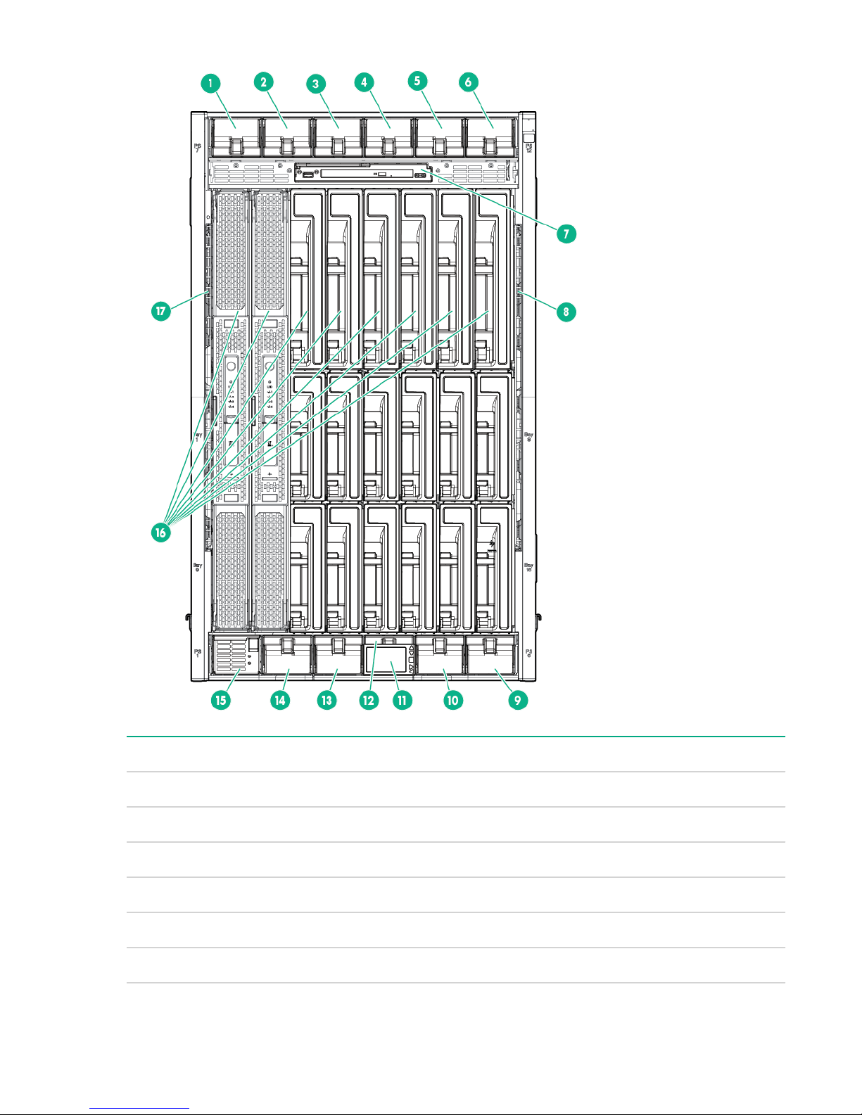
Item Description
1 Power supply bay 7
2 Power supply bay 8
3 Power supply bay 9
4 Power supply bay 10
5 Power supply bay 11
6 Power supply bay 12
Table Continued
HPE Integrity Superdome X overview 11

Item Description
7 DVD module
8 Air intake slot (Do not block)
9 Power supply bay 6
10 Power supply bay 5
11 Insight Display
12 Power supply bay 4
13 Power supply bay 3
14 Power supply bay 2
15 Power supply bay 1
16 Blade slots
17 Air intake slot (Do not block)
12 HPE Integrity Superdome X overview

Power supply bay numbering
HPE Integrity Superdome X overview 13
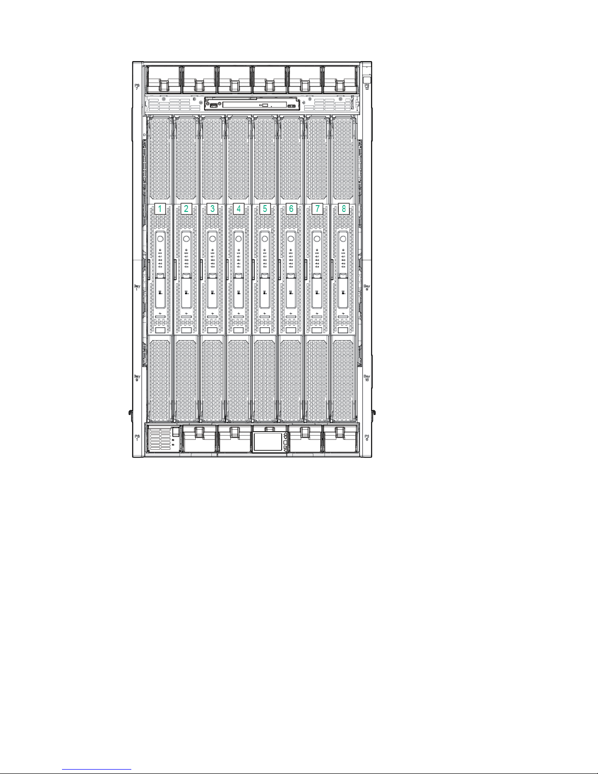
Server blade slot numbering
14 HPE Integrity Superdome X overview
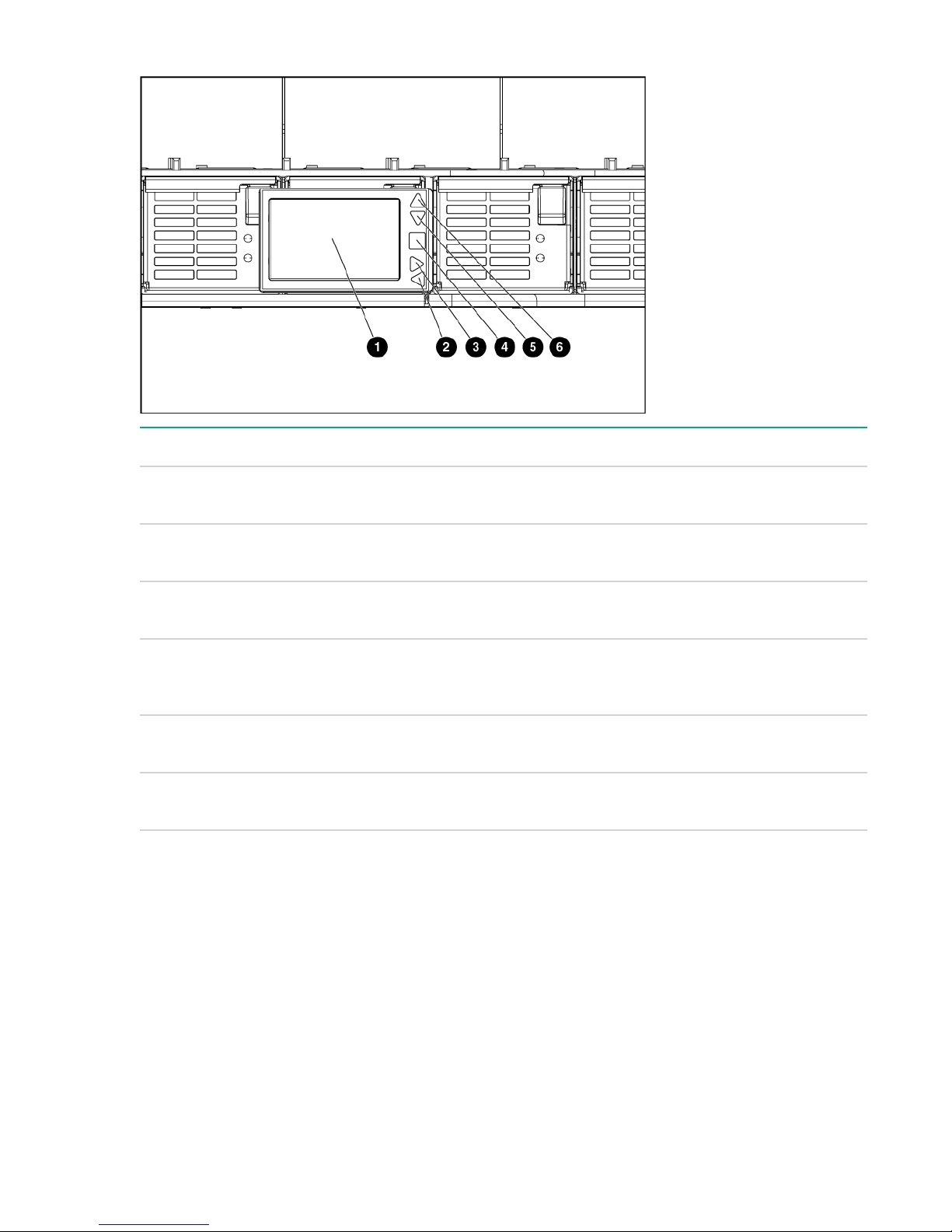
Insight Display components
Item Description Function
1 Insight Display screen Displays Main Menu error
messages and instructions
2 Left arrow button Moves the menu or navigation
bar selection left one position
3 Right arrow button Moves the menu or navigation
bar selection right one position
4 OK button Accepts the highlighted selection
and navigates to the selected
menu
5 Down arrow button Moves the menu selection down
one position
6 Up arrow button Moves up the menu selection one
position
HPE Integrity Superdome X overview 15
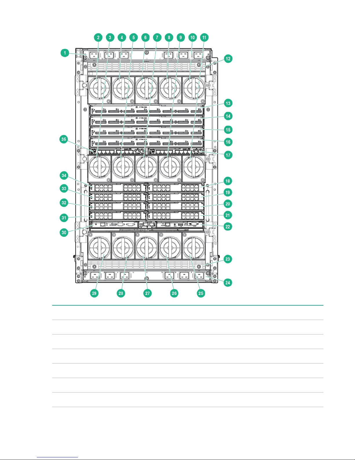
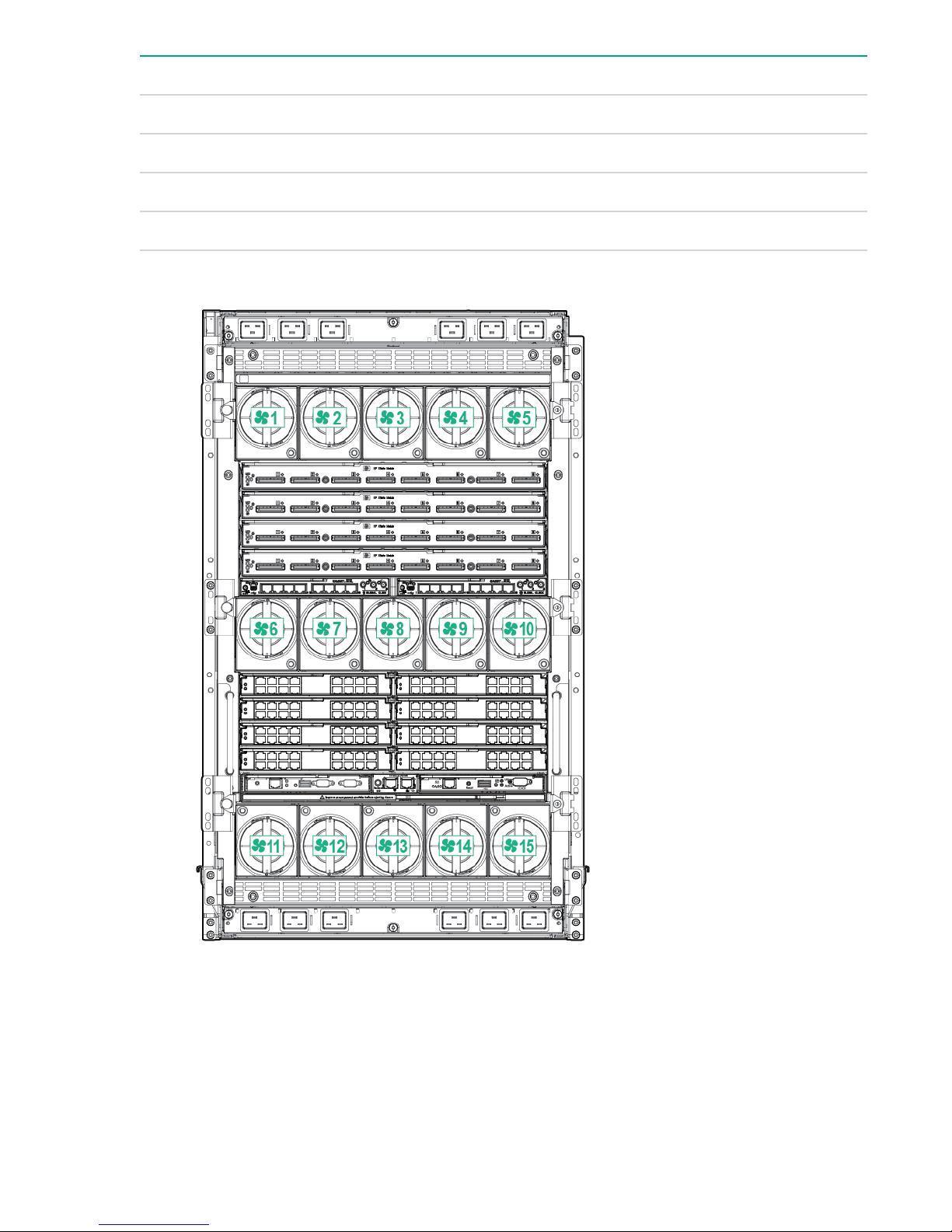
Compute enclosure rear components
Item Description
1 AC power connectors (upper)
2 Fan bay 1
3 Fan bay 6
4 Fan bay 2
5 Fan bay 7
6 Fan bay 3
16 HPE Integrity Superdome X overview
Table Continued

Item Description
7 Fan bay 8
8 Fan bay 4
9 Fan bay 9
10 Fan bay 5
11 Fan bay 10
12 Power supply exhaust vent (Do not block)
13 XFM bay 1
14 XFM bay 2
15 XFM bay 3
16 XFM bay 4
17 GPSM bay 2
18 Interconnect bay 2
19 Interconnect bay 4
20 Interconnect bay 6
21 Interconnect bay 8
22 OA bay 2
23 Power supply exhaust vent (Do not block)
24 AC power connectors (lower)
25 Fan bay 15
26 Fan bay 14
27 Fan bay 13
28 Fan bay 12
29 Fan bay 11
30 OA bay 1
31 Interconnect bay 7
Table Continued
HPE Integrity Superdome X overview 17
Item Description
32 Interconnect bay 5
33 Interconnect bay 3
34 Interconnect bay 1
35 GPSM bay 1
Fan bay numbering
Interconnect bay numbering
Each Integrity Superdome X enclosure requires interconnect modules to provide network access for data
transfer. Interconnect modules reside in bays located in the rear of the enclosure. Review blade slot
numbering to determine which external network connections on the interconnect modules are active.
To support server blade LAN and Fibre Channel I/O connections, an appropriate type of interconnect
module is installed according to bay location.
18 HPE Integrity Superdome X overview
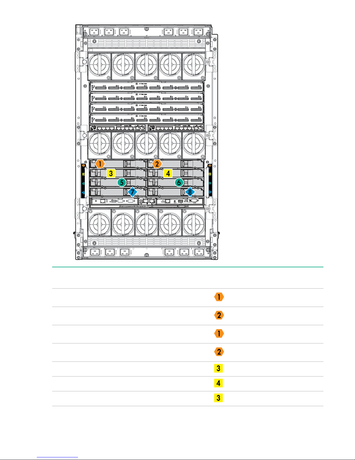
Server blade port Compute enclosure
interconnect bay
FlexLOM 1 port 1 1
FlexLOM 1 port 2 2
FlexLOM 2 port 1 1
FlexLOM 2 port 2 2
Mezzanine 1 port 1 3
Mezzanine 1 port 2 4
Mezzanine 1 port 3 3
Interconnect bay label
Table Continued
HPE Integrity Superdome X overview 19

Server blade port Compute enclosure
interconnect bay
Mezzanine 1 port 4 4
Mezzanine 2 port 1 5
Mezzanine 2 port 2 6
Mezzanine 2 port 3 7
Mezzanine 2 port 4 8
Mezzanine 3 port 1 7
Mezzanine 3 port 2 8
Mezzanine 3 port 3 5
Mezzanine 3 port 4 6
NOTE:
Interconnect bay label
For information on the location of LEDs and ports on individual interconnect modules, see the
documentation that ships with the interconnect module.
More information
• Integrity Superdome X QuickSpecs
Server blade overview
Product Processors DIMM slots Supported
BL920s Gen8
BL920s Gen9
2 48 16 GB and 32
DIMM size
GB (Gen8)
16 GB, 32 GB,
and 64 GB
(Gen9)
PCIe I/O
Mezzanine
card capacity
3 2
PCI I/O
FlexLOM card
capacity
20 Server blade overview
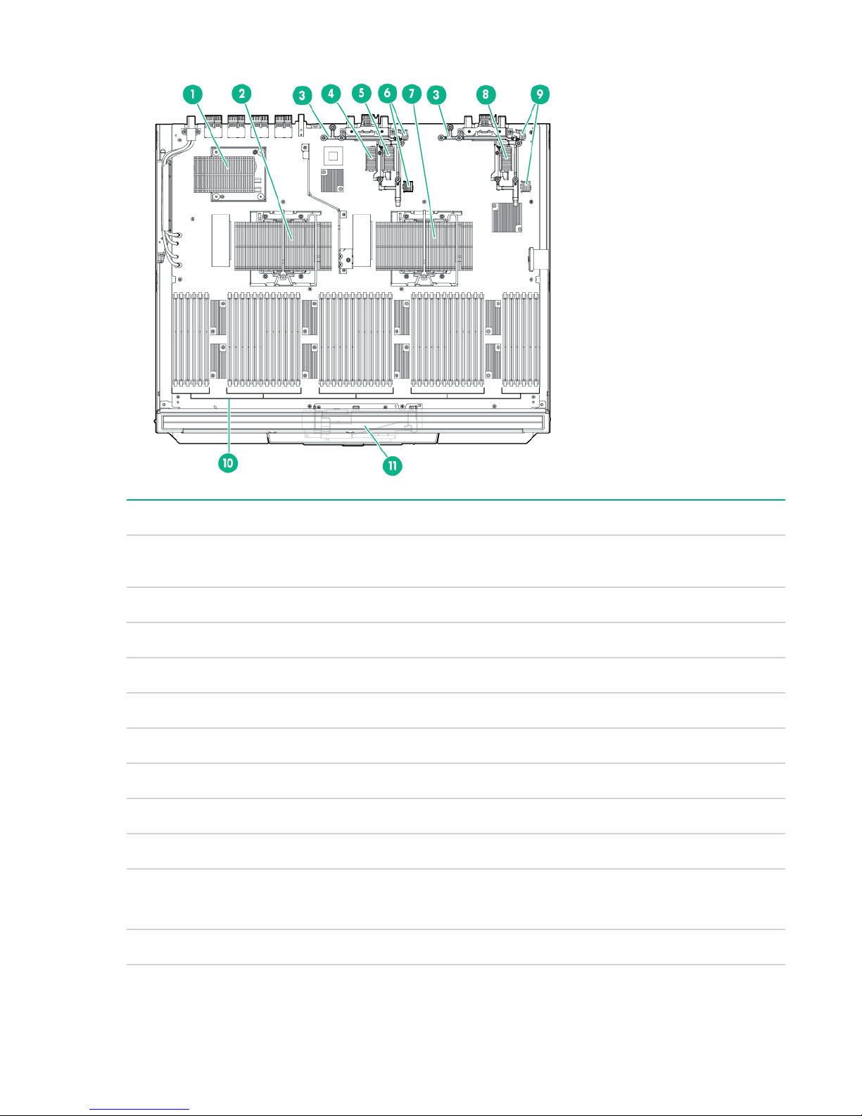
Server blade components
Item Description
1 sx3000 crossbar fabric ASIC (referred to as XNC
by the Health Repository and in event logs)
2 CPU 1
3 Mezzanine bracket
4 Mezzanine connector 1 Type A
5 Mezzanine connector 2 Type A/B
6 FlexLOM slot 2
7 CPU 0
8 Mezzanine connector 3 Type A/B
9 FlexLOM slot 1
10 DDR3 DIMM slots (48) — BL920s Gen8
DDR4 DIMM slots (48) — BL920s Gen9
11 SUV board
HPE Integrity Superdome X overview 21
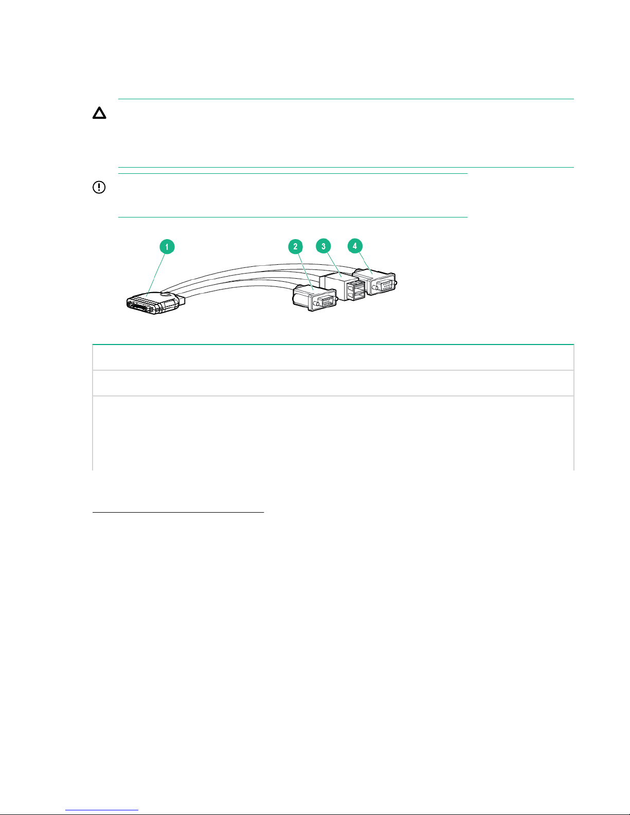
SUV cable and ports
The SUV port on the front of the server blade is used with an SUV cable to connect the blade to external
devices (serial terminal or monitor) or USB devices. The SUV port is located behind a door that stays
closed when an SUV cable is not installed.
CAUTION:
The SUV cable is not designed to be used as a permanent connection; therefore be careful when
walking near the server blade. Hitting or bumping the cable might cause the port on the server blade
to break and damage the blade.
IMPORTANT:
The SUV port does not provide console access and the serial port is unused.
Item Description
1 Server blade connector
2 Serial
3 USB ports (2)
4 Video
More information
Integrity Superdome X QuickSpecs
22 HPE Integrity Superdome X overview

System specifications
Dimensions and weights
Component dimensions
Table 1: Component dimensions
Component Width Depth Height
Compute enclosure 44.7 cm
17.6 in
Server blade 5.13 cm
2.02 in
Component weights
82.8 cm
32.6 in
52.25 cm
20.60 in
79.8 cm
31.4 in
62.18 cm
24.48 in
Table 2: Compute enclosure weights
Component Weight Max. quantity per enclosure
Compute enclosure chassis
I/O chassis
Midplane Brick 18.8 kg
2
1
64.9 kg
143.0 lb
22.1 kg
48.7 lb
41.5 lb
1
1
1
OA tray 3.6 kg
Active Cool Fan 0.9 kg
Power supply module 2.3 kg
Enclosure DVD module 2.1 kg
OA module 0.8 kg
1
8.0 lb
15
2.7 lb
12
5.0 lb
1
4.7 lb
2
1.8 lb
Table Continued
System specifications 23

Component Weight Max. quantity per enclosure
GPSM 1.2 kg
XFM 3.3 kg
I/O interconnect module
3
Server blade 12-16 kg
1
Does not include I/O chassis or Midplane Brick.
2
Part of the enclosure assembly that the XFM and I/O switch modules install into
3
Maximum weight for an interconnect module.
More information
Generic Site Preparation Guide
Rack specifications
2.6 lb
7.3 lb
1.3 kg
2.9 lb
26-35 lb
2
4
8
8
Table 3: Rack specifications
Rack Total
cabinet area
with packing
materials
(H x D x W)
HPE 642
1075 mm
Intelligent
Rack
246.80 x
129.20 x
90 cm
(85.35 x
50.87 x
35.43 in)
HPE 642
1200 mm
Shock
Intelligent
Rack
218.00 x
147.00 x
90 cm
(85.82 x
57.87 x
35.43 in)
U height Width Depth Dynamic
42U 597.8 mm
42U 597.8 mm
(23.54 in)
(23.54 in)
1,085.63 mm
(42.74 in)
1,300.2 mm
(51.19 in)
load
(gross)
1,134 kg
(2,500 lb)
1,460.11 kg
(3,219 lb)
Static load
1,360.8 kg
(3,000 lb)
1,360.78 kg
(3,000 lb)
More information
Generic Site Preparation Guide
24 Rack specifications

Internal and external site door requirements
Internal site doorways must obey the following height requirements:
• For the 642 1075 mm rack — no less than 200.19 cm (78.816 in)
• For the 642 1200 mm rack — no less than 200.66 cm (79.00 in)
To account for the lifted height of the pallet, external doorways must obey the following height
requirements:
• For the 642 1075 mm rack — no less than 216.80 cm (85.35 in)
• For the 642 1200 mm rack — no less than 215.00 cm (84.65 in)
More information
Generic Site Preparation Guide
Electrical specifications
Table 4: Enclosure power options
Source type Source voltage
(nominal)
3–phase 200 VAC to 240
VAC line-to-line
(phase-tophase), 3phase
50/60 Hz
3–phase 220 VAC to 240
VAC line-toneutral 3-phase
50/60 Hz
Single-phase 200 VAC to 240
VAC
50/60 Hz
Plug or
connector type
NEMA L15-30p,
3-Pole, 4-wire,
3 m (10 ft)
power cord
IEC 309, 4pole, 5-wire,
Red, 3 m (10 ft)
power cord
IEC 320
C19-C20
Table 5: Single-phase power cords
Circuit type Power
receptacle
required
30 A 3-phase L15-30R. 3-
pole, 4-wire
16 A IEC 309, 4-
pole, 5-wire, red
16/20 A Singlephase
IEC 320
C19
Number of
power cords
required (per
enclosure)
4
4
12
Part number Description Where used
8120-6895 Stripped end, 240 V International - other
8120-6897 Male IEC309, 240 V International
8121-0070 Male GB-1002, 240 V China
8120-6903 Male NEMA L6-20, 240 V North America/Japan
Internal and external site door requirements 25

Table 6: Enclosure single-phase HPE 2400 W power supply specifications
Specification Value
Power cord IEC-320 C19-C20
Output 2450 W per power supply
Input requirements
Rated input voltage 200–240 VAC
Rated input frequency 50-60 Hz
Rated input current per power supply (maximum) 13.8 A at 200 VAC
13.3 A at 208 VAC
12.6 A at 220 VAC
Maximum inrush current 100 A for 10 ms
Ground leakage current 3.5 mA
Power factor correction 0.98
Table 7: Enclosure 3-phase 2400 W power supply specifications (North America/
Japan)
Specification Value
Power cords (4) NEMA L15-30p
3.0 m (10 ft)
Max input current per line cord 24.0 A at 200 VAC
23.1 A at 208 VAC
Output 2450 W per power supply
Input requirements
Rated input voltage 200–240 VAC line-to-line 3-phase
Rated input frequency 50–60 Hz
Maximum inrush current 100 A for 10 ms
Ground leakage current 3.5 mA
Power factor correction 0.98
26 System specifications

Table 8: Enclosure 3-phase 2400 W power supply specifications (International)
Specification Value
Power cords (4) IEC-309 220–240 VAC, 5-pin, 16 A
3.0 m (10 ft)
Max input current per line cord 12.1 A at 220 VAC
11.1 A at 240 VAC
Output 2450 W per power supply
Input requirements
Rated input voltage 200–240 VAC line-to-neutral 3-phase
Rated input frequency 50-60 Hz
Maximum inrush current 100 A for 10 ms
Ground leakage current 3.5 mA
Power factor correction 0.98
Table 9: Enclosure power requirements
Power required (50–60 Hz) Watts VA
User expected maximum power
1
Typical maximum power or user expected maximum power (input power at the AC input expressed in
1
9065 9250
watts and volt-amps). This figure was developed with the absolute maximum configuration running
applications designed to draw the maximum power possible. It is highly unlikely that any real-world
application will result in this amount of power use for any significant time period.
Table 10: Enclosure PDU power options
Source/Circuit
type
3–phase 60 A 200–240 VAC line-
3–phase 32 A 220–240 VAC line-
Source voltage
(nominal)
to-line (phase-tophase), 3–phase
50/60 Hz
to-neutral 3–phase
50/60 Hz
Plug or connector
type
IEC 309 60 A 3Pole, 4 wire, Blue,
3.6 m (11.8 ft)
power cord
IEC 309 32 A 4Pole, 5 wire, Red,
3.6 m (11.8 ft)
power cord
Power receptacle
required
IEC 309 60 A 3Pole, 4 wire, Blue
IEC 309 32 A 4Pole, 5 wire, Red
Number of power
cords required
(per enclosure
leaving the rack)
2
2
Table Continued
System specifications 27

Source/Circuit
type
Source voltage
(nominal)
Plug or connector
type
Power receptacle
required
Number of power
cords required
(per enclosure
leaving the rack)
Single-phase 63 A 200–240 VAC
50/60 Hz
Single-phase 30 A 200–240 VAC
50/60 Hz
More information
Generic Site Preparation Guide
IEC 309 63 A
Single Phase Blue,
3.6 m (11.8 ft)
power cord
NEMA L6-30P
Single Phase,
3.6 m (11.8 ft)
power cord
Environmental specifications
Temperature and humidity specifications
The following table contains the allowed and recommended temperature and humidity limits for both
operating and nonoperating Integrity Superdome X systems.
Specification Value
IEC 309 63 A
Single Phase, Blue
NEMA L6-30R
Single Phase
4
6
Temperature range
Allowable Operating Range
Recommended Operating Range +18° C to +27° C (64° F to 81° F)
Nonoperating (powered off) +5° C to +45° C (41° F to 113° F)
Nonoperating (storage) -40° C to +80° C (-40° F to 176° F)
Humidity Range (noncondensing)
Allowable Operating Range -12° C DP and 8% RH to +24° C DP and 85% RH
Recommended Operating Range +5.5° C DP to +15° C DP and 65% RH
Nonoperating (powered off) 8% RH to 90% RH and 29° C DP
Nonoperating (storage) 8% RH to 90% RH and 32° C DP
1
All temperature ratings shown are for sea level. An altitude derating of 1° C per 300 m above 900 m is
applicable. No direct sunlight allowed. Upper operating limit is 3,048 m (10,000 ft) or 70 Kpa/10.1 psia.
Upper nonoperating (storage) limit is 9,144 m (30,000 ft) or 30.3 KPa/4.4 psia.
2
The Recommended Operating Range is recommended for continuous operation. Operating within the
Allowable Operating Range is supported but might result in a decrease in system performance.
1
2
+5° C to +40° C (41° F to 104° F)
28 Environmental specifications

More information
Generic Site Preparation Guide
Cooling requirements
Integrity Superdome X is a rack-mounted system that cools by drawing air in the front and exhausting it
out the rear. General ASHRAE best practices must be followed when installing the system in a data
center.
• Hot/cold aisle layout
• Appropriate blanking panels in any unused space in the rack.
• No gaps exist between adjacent racks, which ensures minimal air recirculation.
• An adequate hot-air return path to the computer room air conditioners (CRAC) or computer room air
handlers (CRAH), which minimizes the flow of hot air over any rack.
Integrity Superdome X utilizes variable speed fans to realize the most efficient use of air. The volume of
air required varies with the temperature of the air supplied to the inlet.
IMPORTANT:
The optimal equipment orientation is a parallel layout to the air flow supply and return. Supply air
will flow down cold aisles which are parallel to equipment rows, and return air to CRAC through
parallel air flow. Perpendicular air flow causes too much room mixing, places higher electrical loads
on the room, and can lead to unexpected equipment problems.
More information
Generic Site Preparation Guide
Air quality specifications
Chemical contaminant levels in customer environments for Hewlett Packard Enterprise hardware
products must not exceed G1 (mild) levels of Group A chemicals at any time. These contaminant levels
are described in the current version of ISA–71.04 Environmental Conditions for Process Measurement
and Control Systems: Airborne Contaminants.
More information
• Generic Site Preparation Guide
• ISA–71.04 Environmental Conditions for Process Measurement and Control Systems: Airborne
Contaminants
Acoustic noise specifications
The acoustic noise specifications are 8.6 bel (86 dB) (sound power level).
IMPORTANT:
Hewlett Packard Enterprise recommends that anyone in the immediate vicinity of the product for
extended periods of time wear hearing protection or use other means to reduce noise exposure.
This level of noise is appropriate for dedicated computer room environments, not office environments.
Understand the acoustic noise specifications relative to operator positions within the computer room when
adding Integrity Superdome X systems to computer rooms with existing noise sources.
More information
Generic Site Preparation Guide
Cooling requirements 29

Sample site inspection checklist for site preparation
See Customer and Hewlett Packard Enterprise Information and Site inspection checklist. You can
use these tables to measure your progress.
Table 11: Customer and Hewlett Packard Enterprise Information
Customer Information
Name: Phone number:
Street address: City or Town:
State or province: Country
Zip or postal code:
Primary customer contact: Phone number:
Secondary customer contact: Phone number:
Traffic coordinator: Phone number:
Hewlett Packard Enterprise information
Sales representative: Order number:
Representative making survey: Date:
Scheduled delivery date:
Table 12: Site inspection checklist
Check either Yes or No. If No, include comment or date.
Computer Room
Number Area or condition Yes No Comment or
Date
1. Do you have a completed floor plan?
2. Is adequate space available for maintenance needs?
Front 91.4 cm (36 inches) minimum and rear 91.4 cm
(36 inches) minimum are recommended clearances.
3. Is access to the site or computer room restricted?
4. Is the computer room structurally complete? Expected
date of completion?
30 Sample site inspection checklist for site preparation
Table Continued
 Loading...