

Page 1

HP Integrity Superdome 2 Onboard Administrator User Guide
Abstract
This document contains specific information that is intended for users of this HP product.
HP Part Number: AH337-9001G
Published: November 2013
Edition: 9
Page 2

© Copyright 2010 – 2013 Hewlett-Packard Development Company, L.P.
Notices
The information contained herein is subject to change without notice. The only warranties for HP products and services are set forth in the express
warranty statements accompanying such products and services. Nothing herein should be construed as constituting an additional warranty. HP shall
not be liable for technical or editorial errors or omissions contained herein.
Confidential computer software. Valid license from HP required for possession, use or copying. Consistent with FAR 12.211 and 12.212, Commercial
Computer Software, Computer Software Documentation, and Technical Data for Commercial Items are licensed to the U.S. Government under
vendor's standard commercial license.
Microsoft®, Windows®, and Windows Server® are U.S. registered trademarks of Microsoft Corporation. Java® is a registered trademark of Oracle
and/or its affiliates. UNIX® is a registered trademark of the Open Group.
Oracle® is a registered U.S. trademark of Oracle Corporation, Redwood City, California.
Revision History
Publication DateEditionHP Part Number
August 2010FirstAH337-9001A
November 2010SecondAH337-9001A_ed2
December 2010ThirdAH337-9001A_ed3
April 2011FourthAH337-9001B
August 2011FifthAH337-9001C
December 2011SixthAH337-9001D
December 2012SeventhAH337-9001E
May 2013EighthAH337-9001F
November 2013NinthAH337-9001G
Page 3

Contents
1 Introduction...............................................................................................8
Overview................................................................................................................................8
Access requirements................................................................................................................10
Onboard Administrator overview..............................................................................................11
Detecting component insertion and removal..........................................................................11
Identifying components.......................................................................................................11
Managing power and cooling.............................................................................................12
Controlling components......................................................................................................12
Managing partitions..........................................................................................................12
Interfaces...............................................................................................................................12
Onboard Administrator user interfaces..................................................................................13
Onboard Administrator authentication..................................................................................13
Running Onboard Administrator for the first time.........................................................................14
Logging on to the Onboard Administrator GUI...........................................................................15
Running the setup wizard.........................................................................................................15
Using online help...................................................................................................................16
Changing enclosure and device configurations...........................................................................16
Recovering the administrator password......................................................................................17
2 HP Integrity Superdome 2 Insight Display....................................................18
HP Integrity Superdome 2 Insight Display components.................................................................18
Insight Display overview..........................................................................................................18
Running the Insight Display installation......................................................................................19
Navigating the Insight Display..................................................................................................23
Health Summary screen......................................................................................................24
Enclosure Settings screen....................................................................................................25
Enclosure Info screen..........................................................................................................26
Blade and Port Info screen...................................................................................................27
Turn Enclosure UID On/Off screen.......................................................................................28
View User Note screen.......................................................................................................29
Chat Mode screen.............................................................................................................29
Insight Display errors...............................................................................................................30
Power errors......................................................................................................................30
Cooling errors...................................................................................................................30
Location errors...................................................................................................................31
Configuration errors...........................................................................................................31
Device failure errors...........................................................................................................31
3 HP Superdome 2 Door Status Display.........................................................32
Before running Door Display setup............................................................................................32
Setting up the Door Display.....................................................................................................32
Door Display status menu....................................................................................................36
Display Settings menu........................................................................................................38
Firmware Update menu.......................................................................................................39
4 First Time Setup Wizard............................................................................41
Before you begin....................................................................................................................41
Enclosure Selection screen.......................................................................................................41
Configuration Management screen...........................................................................................42
Rack and Enclosure Settings screen...........................................................................................43
Administrator Account Setup screen..........................................................................................44
Local User Accounts screen......................................................................................................45
Enclosure Bay IP Addressing screen...........................................................................................47
Contents 3
Page 4

Directory Groups screen..........................................................................................................48
Directory Settings screen..........................................................................................................49
Onboard Administrator Network Settings screen.........................................................................50
SNMP Settings screen.............................................................................................................50
Power Management screen......................................................................................................51
Finish....................................................................................................................................53
5 Navigating Onboard Administrator............................................................55
Navigation overview...............................................................................................................55
Tree view..........................................................................................................................55
Graphical view navigation..................................................................................................57
6 Complex Overview...................................................................................60
Complex Overview screen.......................................................................................................60
Compute Enclosures tab......................................................................................................61
Power and Thermal tab.......................................................................................................61
Complex Information screen.....................................................................................................63
Status tab.........................................................................................................................63
Information tab..................................................................................................................65
Complex Logs tab..............................................................................................................67
Complex CLI Tab...............................................................................................................67
Complex Information: Firmware Management.............................................................................67
Complex Firmware Summary screen.....................................................................................67
Online complex firmware update on Superdome 2.................................................................68
Introduction..................................................................................................................68
Services unavailable......................................................................................................69
Management Processor access........................................................................................69
IPMI............................................................................................................................70
Event logs....................................................................................................................70
IPMI Watchdog.............................................................................................................70
Partition ID...................................................................................................................70
Console.......................................................................................................................71
System Firmware Services During Boot, Shutdown, etc........................................................71
Affected OS Commands.................................................................................................72
Network Services to OA.................................................................................................72
Frequently asked questions:............................................................................................72
Known issues:...............................................................................................................73
hpvminfo command qualifiers fail...............................................................................73
Newly created HPVM guests cannot be started.............................................................73
Serviceguard Manager performance degradation and proxy errors................................74
cimserver shutdown and startup fail............................................................................74
cimauth is unable to add authorizations.......................................................................74
cprop command qualifiers fail....................................................................................74
SMH is unable to query memory or enclosure information..............................................74
setboot and related commands are unable to display or modify boot variables................74
wbemassist namespace error.....................................................................................74
par* and vpar* commands fail..................................................................................74
Firmware Update screen.....................................................................................................74
Enclosure DVD Module screen..................................................................................................77
7 Configuring HP Integrity Superdome 2 compute enclosures and enclosure
devices......................................................................................................79
Viewing the status screens........................................................................................................79
Enclosure settings...................................................................................................................80
Enclosure Settings screen....................................................................................................80
Enclosure Information tab...............................................................................................82
4 Contents
Page 5

AlertMail screen................................................................................................................83
Device Power Sequence Device Bays tabs.............................................................................85
Device Power Sequence Interconnect Bays tab...................................................................87
Date and Time screen.........................................................................................................87
Enclosure TCP/IP Settings screen..........................................................................................88
Network Access screen.......................................................................................................89
Trusted Hosts tab...........................................................................................................90
Anonymous Data tab.....................................................................................................91
Link Loss Failover screen......................................................................................................91
Enclosure Bay IP Addressing screen......................................................................................91
SNMP Settings screen........................................................................................................94
Configuration Scripts screen................................................................................................96
Device Summary screen......................................................................................................97
Active to Standby screen.....................................................................................................98
Onboard Administrator Module................................................................................................98
Active Onboard Administrator screen...................................................................................98
Active Onboard Administrator Status and Information tab...................................................99
Active Onboard Administrator Virtual Buttons tab............................................................100
TCP/IP Settings screen.................................................................................................101
Certificate Administration screen...................................................................................102
Certificate Request tab............................................................................................103
Active Onboard Administrator Certificate Upload tab..................................................106
System log.................................................................................................................106
Log Options tab.....................................................................................................109
Standby Onboard Administrator screen..............................................................................109
TCP/IP Settings for Standby Onboard Administrator........................................................110
Standby Onboard Administrator Virtual Buttons tab.........................................................110
Standby Certificate Request tab.....................................................................................110
Standby Onboard Administrator Certificate Upload tab...................................................110
Device bays.........................................................................................................................111
Device Bay Overview screen.............................................................................................111
Device Bay Information - Bay xx screen...............................................................................113
Device Bay Information tab...........................................................................................116
Device bay virtual buttons tab.......................................................................................118
Interconnect bays..................................................................................................................118
Interconnect Bay Summary screen......................................................................................118
Interconnect Bay Information screen....................................................................................119
Interconnect Bay Information tab...................................................................................121
Interconnect Bay Virtual Buttons tab...............................................................................122
Port Mapping - Interconnect Bay screen...............................................................................122
XFM bays............................................................................................................................123
XFM Bay Summary screen.................................................................................................123
XFM Bay Information - Bay screen......................................................................................124
XFM Bay Status tab.....................................................................................................125
XFM Bay Information tab..............................................................................................126
XFM Bay Virtual Buttons...............................................................................................126
GPSM bays.........................................................................................................................127
GPSM Bay Summary screen..............................................................................................127
GPSM Bay Information screen...........................................................................................128
GPSM Status tab.........................................................................................................128
GPSM Bay Information tab...........................................................................................129
GPSM Virtual Buttons...................................................................................................129
Enclosure power management................................................................................................129
Planning power management ...........................................................................................129
Power and Thermal screen.................................................................................................130
Contents 5
Page 6

Power Management screen...........................................................................................131
Enclosure Power Allocation screen.................................................................................132
Enclosure Power Meter screen.......................................................................................133
Power Subsystem screen....................................................................................................133
Power Supply Information - Bay screen...........................................................................135
Fans and cooling management..........................................................................................136
Thermal Subsystem screen............................................................................................136
Thermal Subsystem Fan Zones tab.................................................................................137
Superdome 2 Enclosure fan location rules..................................................................139
Fan Information - Bay screen.........................................................................................139
Managing users...................................................................................................................140
Users/Authentication........................................................................................................140
User roles and privilege levels............................................................................................141
Role-based user accounts..................................................................................................141
Local Users screen............................................................................................................142
Add Local User...........................................................................................................142
Edit Local User............................................................................................................143
Edit Local User Certificate Information tab.......................................................................145
Password Settings screen...................................................................................................145
Directory Settings screen...................................................................................................146
Uploading a certificate................................................................................................146
Directory Certificate Upload tab....................................................................................147
Directory Test Settings tab............................................................................................147
Directory Groups.............................................................................................................149
Add an LDAP Group screen..........................................................................................150
Edit an LDAP Group screen...........................................................................................151
SSH Administration screen................................................................................................152
HP SIM Integration screen.................................................................................................153
Edit Local User Certificate Information tab.......................................................................154
Two-Factor Authentication screen............................................................................................154
Two-Factor Authentication Certificate Information tab............................................................154
Two-Factor Authentication Certificate Upload tab.................................................................155
Signed In users.....................................................................................................................155
Session Options tab.........................................................................................................156
Insight Display.....................................................................................................................156
Management network IP dependencies....................................................................................156
8 HP Integrity Superdome 2 IOX Enclosures..................................................157
IOX Enclosure Information screen............................................................................................157
IOX Power and Thermal screen...............................................................................................159
IOX Power Subsystem screen..................................................................................................160
IOX Power Supply screen..................................................................................................161
IOX Thermal Subsystem screen...............................................................................................161
9 Port mapping.........................................................................................163
Device bay port mapping for Superdome 2 Compute Enclosures.................................................163
Device bay port mapping tabular view for Superdome 2 compute enclosures...............................163
10 Using the CLI.......................................................................................164
Command line overview........................................................................................................164
11 Using the serial connection.....................................................................165
Setting up Onboard Administrator using the CLI.......................................................................165
Pinout signals for Onboard Administrator Serial RS232 connector...............................................165
Using the service port connection...........................................................................................166
6 Contents
Page 7

12 Using configuration scripts.....................................................................167
Configuration scripts.............................................................................................................167
Reset Factory Defaults screen..................................................................................................168
13 Troubleshooting....................................................................................169
Onboard Administrator error messages...................................................................................169
Onboard Administrator factory default settings.........................................................................178
Onboard Administrator SNMP traps.......................................................................................179
14 Enabling LDAP Directory Services Authentication to Microsoft Active
Directory..................................................................................................181
Certificate Services...............................................................................................................181
Preparing the directory..........................................................................................................181
Uploading the DC certificate (optional)...................................................................................182
Creating directory groups......................................................................................................184
Testing the directory login solution..........................................................................................185
Troubleshooting LDAP on Onboard Administrator......................................................................185
15 Support and other resources...................................................................187
Before you contact HP...........................................................................................................187
HP contact information..........................................................................................................187
Subscription service..............................................................................................................187
Documentation feedback.......................................................................................................187
Installing HP Insight Remote Support Software..........................................................................187
New and changed information in this edition...........................................................................188
Related information...............................................................................................................188
Typographic conventions.......................................................................................................188
A Time zone settings..................................................................................190
Africa time zone settings........................................................................................................190
Americas time zone settings...................................................................................................190
Asia time zone settings..........................................................................................................192
Universal time zone settings...................................................................................................192
Oceanic time zone settings....................................................................................................193
Europe time zone settings......................................................................................................193
Polar time zone settings.........................................................................................................194
Standard terms, abbreviations, and acronyms...............................................195
Index.......................................................................................................196
Contents 7
Page 8

1 Introduction
Overview
HP Superdome 2 Onboard Administrator is the complex management processor, subsystem, and
firmware base used to support HP Integrity Superdome 2 complexes and all the managed devices
contained within the complex.
Onboard Administrator provides a single point from which to perform basic management tasks
for the following complex devices:
• Compute enclosures
• IOXs
• Server blades
• I/O interconnects
Onboard Administrator performs configuration steps for the complex, enables run-time management
and configuration of the complex components, and informs you of problems within the complex
through email, SNMP, or the Insight Display.
HP recommends that you read the HP Integrity Superdome 2 User Service Guide for complex
specific information before proceeding with the Onboard Administrator setup.
This user guide provides information on the following topics:
• Initial setup and operation of the HP Superdome 2 Onboard Administrator
• Use of the Onboard Administrator GUI
• Use of the compute enclosure Insight Display
• Initial setup and operation of the HP Superdome 2 Door Status Display
The HP Integrity Superdome 2 Onboard Administrator Command Line Interface User Guide covers
the use of the CLI.
The HP Superdome 2 Onboard Administrator provides several features designed to simplify
management of Superdome 2 enclosures, blades, and interconnects. Compute enclosures within
a Superdome 2 complex can be configured with redundant Onboard Administrator modules to
provide uninterrupted manageability of the entire complex in the event of a failure of a single
Onboard Administrator module.
The following table lists which Onboard Administrator feature is enhanced when an enclosure
contains redundant Onboard Administrator modules. For an enclosure with only a single Onboard
Administrator module, the table indicates the behavior of the enclosure if the single Onboard
Administrator module has failed or is removed.
Table 1 Benefits of using a redundant Onboard Administrator versus a single Onboard Administrator
Onboard Administrator
feature
of all blades and
interconnects. of either Onboard
Single Onboard
Administrator in enclosure
Yes. Complete control.Power allocation and control
Single Onboard
Administrator failed or
removed
No. Power supplies continue
to deliver power to all
blades and interconnects.
No power on requests can
be made for blades or
interconnects.
Redundant Onboard
Administrator in enclosure
Yes. Complete control,
including sustaining a failure
Administrator.
interconnects.
8 Introduction
Yes. Complete control.Cooling for all blades and
No. All enclosure fans will
ramp to an un-managed
higher speed to protect
Yes. Complete control,
including sustaining a failure
of either Onboard
Administrator.
Page 9

Table 1 Benefits of using a redundant Onboard Administrator versus a single Onboard Administrator
(continued)
Onboard Administrator
feature
Onboard Administrator,
server iLO 3, interconnect
management processors
which use the Onboard
Administrator/iLO
management port.
reporting for all blades,
interconnects, fans, power
supplies, Onboard
enclosure through the
Onboard Administrator GUI
or CLI, AlertMail, or SNMP.
Single Onboard
Administrator in enclosure
Yes. Complete control.EBIPA.
Yes. Complete control.Ethernet communications to
Yes. Complete control.Information and health status
Single Onboard
Administrator failed or
removed
blades and interconnects
from overheating.
No. EBIPA IP addresses are
lost after lease timeout.
No. Ethernet management
communications are not
available, including internal
management traffic such as
Virtual Connect Manager tosuch as Virtual Connect,
other VC modules in the
enclosure.
No. Additionally, no
information is available from
the Onboard Administrator,
and no out-of-band
information is available fromAdministrators, and
VCM or iLO 3 on any
server.
Redundant Onboard
Administrator in enclosure
Yes. Complete control,
including sustaining a failure
of either Onboard
Administrator.
Yes. Complete control,
including sustaining a failure
of either Onboard
Administrator.
Yes. Complete control,
including sustaining a failure
of either Onboard
Administrator.
No.Yes. Complete control.Insight Display.
No.Yes. Complete control.Enclosure DVD.
Yes. Complete control,
including sustaining a failure
of either Onboard
Administrator.
Yes. Complete control,
including sustaining a failure
of either Onboard
Administrator.
Onboard Administrator module replacement and stored settings
When replacing an Onboard Administrator or if a failure occurs when using redundant Onboard
Administrators:
• Removing an Onboard Administrator module in a Superdome 2 enclosure with a redundant
Onboard Administrator module installed results in the other Onboard Administrator module
immediately becoming the active Onboard Administrator if it was the standby Onboard
Administrator. Only the network settings of the replaced Onboard Administrator network
settings are lost.
• If Onboard Administrator complex firmware versions are identical, manually update the
replaced Onboard Administrator network settings using the Insight Display. The replaced
Onboard Administrator module gets automatically synchronized on all enclosure settings by
the active Onboard Administrator.
NOTE: If the enclosure IP mode is enabled, then both Onboard Administrators have the
same network settings and no manual update is required.
• If the complex firmware versions are not identical, the Onboard Administrator GUI and
Onboard Administrator CLI can be used to synchronize the firmware versions to the most
recent version in the modules, followed by synchronization of the active Onboard Administrator
configuration settings to the new standby Onboard Administrator module.
Overview 9
Page 10

IMPORTANT: You cannot update firmware through the HP Superdome 2 Onboard
Administrator GUI if you have complex firmware earlier than the Online Firmware Update
firmware release.
To update complex firmware if you have complex firmware earlier than the Online Firmware
Update firmware release, see the “Update Firmware” section in the HP Integrity Superdome
2 Onboard Administrator Command Line Interface User Guide.
Access requirements
To access the HP Superdome 2 Onboard Administrator web interface, you require the Onboard
Administrator IP address and a compatible web browser. You must access the application through
HTTPS (HTTP packets exchanged over an SSL-encrypted session).
The Superdome 2 Onboard Administrator web interface requires an XSLT-enabled browser with
support for JavaScript 1.3 or the equivalent.
The following browsers are officially supported for use with Onboard Administrator:
• Microsoft Internet Explorer 7.0 or later
• Mozilla Firefox 2 or later
NOTE: Other browsers can be used but are not supported.
Before running the application, you must enable the following browser settings:
• ActiveX (for Microsoft Internet Explorer)
• Cookies
• JavaScript
If you receive a notice that your browser does not have the required functionality, be sure that your
browser settings meet the preceding requirements and see “Recovering the administrator password”
(page 17).
To access the HP Superdome 2 Onboard Administrator CLI, use the Onboard Administrator IP
address and a terminal or terminal application. To access the CLI interface, you must use Telnet
or Secure Shell depending on which of these protocols are enabled.
To access the CLI management and notification features, the ports listed on the following table
must be open on any router between Onboard Administrator and any computers used to access
or monitor Onboard Administrator.
Outgoing portIncoming portProtocol
22Secure Shell
23Telnet
25SMTP
8080Browser access
443443Browser access encrypted
PC to OA
10 Introduction
161SNMP get/set
162SNMP traps
636LDAP
3389Terminal services pass-through from
Page 11

17988Virtual media from PC to OA
LDAP and Remote syslog port number can be changed.
If a protocol is disabled, the corresponding ports are also disabled.
Onboard Administrator overview
NOTE: The Monarch OA is the Active OA in enclosure 1. It provides complex-wide administrative
functions, such as partition management, event logs, and error diagnostics. IOX enclosure devices
are managed through the Monarch OA.
Many OA settings must be managed on the Monarch OA and are automatically copied to the
other OAs in the complex, such as user accounts and settings, power options, and feature
enablement. Some settings are managed locally on each OA, such as the IP configuration and
OA certificates.
Detecting component insertion and removal
Onboard Administrator provides component control in HP Integrity Superdome 2 Blade Enclosures.
Component management begins after the component is detected and identified. The Onboard
Administrator detects components in Superdome 2 enclosures through presence signals on each
bay. When you insert a component into a bay, or connect an IOX, the Onboard Administrator
immediately recognizes and identifies the component. If you remove a component from a bay the
Onboard Administrator deletes the information about that component. An IOX will be marked
Failed if it is disconnected while the system is active. The Monarch OA must be rebooted to remove
an IOX from the complex.
Outgoing portIncoming portProtocol
514Remote syslog
Identifying components
To identify a component, Onboard Administrator reads an FRU EEPROM that contains specific
factory information about the component such as product name, part number, and serial number.
All FRU EEPROMs in Superdome 2 enclosures are powered on, even if the component is powered
off. Therefore, Onboard Administrator can identify the component before granting power. For
devices such as fans, power supplies, and Insight Display, Onboard Administrator directly reads
the FRU EEPROMs.
• The server blades contain several FRU EEPROMs: one on the server board, which contains
server information and embedded NIC information, and one on each installed mezzanine
option cards.
• Server blade control options also include extensive blade hardware information including:
Blade and partition firmware versions◦
◦ Blade name
◦ NIC and option card port IDs
◦ Port mapping
• Onboard Administrator provides easy-to-understand port mapping information for each server
blade and interconnect module in each enclosure.
The NIC and mezzanine option FRU data informs Onboard Administrator of the type of interconnects
each server requires. Before power is provided to a server blade, Onboard Administrator compares
this information with the FRU EEPROMs on installed interconnect modules to verify for electronic
Onboard Administrator overview 11
Page 12

keying errors. For interconnect modules, Onboard Administrator provides virtual power control,
dedicated serial consoles, and management Ethernet connections.
While Onboard Administrator is identifying components, the progress appears as steps on the
Insight Display. Discovery might take several minutes, and the number of installed mezzanine cards
on each server increases the time taken as each card is identified and verified.
Managing power and cooling
The most important Onboard Administrator tasks are power control and thermal management.
Onboard Administrator can remotely control the power state of all components in Superdome 2
compute enclosures. For components in device bays on the front of each enclosure, Onboard
Administrator communicates with iLO 3 to control blades, and with a microcontroller to control
options such as storage blades. A separate microcontroller controls power to the interconnect
modules.
After the components are powered on, the Onboard Administrator begins thermal management
with Thermal Logic. The Thermal Logic feature in Superdome 2 minimizes power consumption by
the enclosure fan subsystem by reading temperature sensors across the entire enclosure. Then,
Thermal Logic changes the fan speed in the various zones in the enclosure to minimize power
consumption and maximize cooling efficiency.
Controlling components
Onboard Administrator uses embedded management interfaces to provide detailed information
and health status of all bays in the enclosure including presence detection signals in each bay,
i2c, serial, USB, and Ethernet controllers. Onboard Administrator also offers information on firmware
versions for most components in the enclosure and can be used to update those components.
Managing partitions
The Onboard Administrator also enables users to define and manage partitions in a Superdome
2 complex.
An nPartition comprises one or more Superdome 2 Server Blades working as a single system. I/O
bays in IOX enclosures are assigned to nPartitions and any I/O component of a server blade,
including NICs and mezzanine cards are assigned to the nPartition containing the server blade.
In the complex, each nPartition has its own dedicated portion of the complex hardware which can
run a single instance of an operating system. Each nPartition can boot, reboot, and operate
independently of any other nPartitions and hardware within the same complex.
An nPartition includes all hardware assigned to the nPartition: all IOX I/O bays, I/O devices, and
server blades.
A complex can contain one or more nPartitions, enabling the hardware to function as a single
system or as multiple systems.
NOTE: For more information about partition creation and management, see the HP Integrity
Superdome 2 Partitioning Administrator Guide.
Interfaces
Each Superdome 2 compute enclosure has several external management interfaces that connect
the user to Onboard Administrator. The primary external management interface is the management
port for Onboard Administrator, which is an RJ-45 jack providing Ethernet communications not
only to Onboard Administrator, but also to every device or interconnect bay with a management
processor.
A serial port on the Onboard Administrator module provides full out-of-band CLI access to the
Onboard Administrator.
12 Introduction
Page 13

All Superdome 2 enclosures support two enclosure link connectors that provide private
communications among enclosures linked with CAT5 cable. In addition, the enclosure link-up
connector provides an enclosure service port that enables you to temporarily connect a personal
laptop computer to any linked enclosure Onboard Administrator for local diagnostics and
debugging.
NOTE: For complexes that have the HP Superdome 2 Door Status Display, the enclosure service
port is routed through the rack-mounted E-Switch.
Each Superdome 2 compute enclosure includes an embedded Insight Display on the front of the
enclosure, which provides status and information on all the bays in a Superdome 2 compute
enclosure and diagnostic information if the Onboard Administrator detects a problem in the
enclosure. The Insight Display configures key settings in the Onboard Administrator, including the
IP address of the Onboard Administrator.
Onboard Administrator user interfaces
The following user interfaces to the Onboard Administrator enable control and provide information
about the enclosure and installed components:
• Web interface GUI
• Scriptable CLI
• Insight Display
Remote network access to the Onboard Administrator GUI and CLI is available through the
management Ethernet port. The serial port of the Onboard Administrator is available for local CLI
access. The Superdome 2 compute enclosure link-up port is also available as the service port for
temporary local Ethernet access to the Onboard Administrators and devices in linked enclosures
using either the GUI or CLI.
NOTE: For complexes that have the HP Superdome 2 Door Status Display, the enclosure service
port is routed through the rack-mounted E-Switch.
Access the Insight Display directly through the buttons on the display, or remotely through the
Onboard Administrator GUI.
Onboard Administrator authentication
Security is maintained for all Onboard Administrator user interfaces through user authentication.
User accounts created in the Onboard Administrator define three user privilege levels and the
component bays to which each level is granted access. Onboard Administrator stores the passwords
for Local User accounts and can be configured to use LDAP authentication for user group accounts.
The Insight Display can be protected by an LCD PIN code or completely disabled.
NOTE: User accounts are managed on the Monarch OA.
Role-based user accounts
Onboard Administrator provides configurable user accounts that can provide complete isolation
of multiple administrative roles such as server, LAN, and SAN. User accounts are configured with
specific device bay or interconnect bay permissions and one of the three privilege levels:
• Administrator
• Operator
• User
An account with administrator privileges including Onboard Administrator bay permissions can
create or edit all user accounts on an enclosure. Operator privileges allow full information access
and control of permitted bays. User privileges allow information access, but no control capability.
Interfaces 13
Page 14

Onboard Administrator requires the user to log in to the web GUI or CLI with an account and
password. The account can be a local account where the password is stored on Onboard
Administrator, or an LDAP account. The Onboard Administrator contacts the defined LDAP server
to verify the user credentials. Two-factor Authentication enables even tighter security for the user
management session to Onboard Administrator.
The default Administrator account from the Monarch OA is synchronized to the other OAs in the
complex. Use the default credentials from the Monarch OA to access all OAs.
Rather than requiring separate logins to multiple resources (once to each enclosure or once to
every server management processor or both), Onboard Administrator enables single-point access.
Thus, the administrator can use single sign-on to log in to a single Onboard Administrator and use
the web GUI to graphically view and manage the HP Superdome 2 components in the entire
complex. For example, an IT administrator can automatically propagate management commands,
such as changing the enclosure power mode, throughout the complex.
Running Onboard Administrator for the first time
Setting up a Superdome 2 enclosure using the Onboard Administrator is simplified by using the
Insight Display setup process, followed by the use of the Onboard Administrator GUI First Time
Setup Wizard or Onboard Administrator CLI to complete the reset of the enclosure settings.
The Onboard Administrator modules and many interconnect modules default to DHCP for the
management IP address. If the user has DHCP and connects the Onboard Administrator management
port to the DHCP server, then the Onboard Administrator modules and interconnect modules
supporting and configured to use the Onboard Administrator internal management network
automatically get DHCP addresses from the user DHCP server.
If you do not have a DHCP server for assigning IP addresses to management processors, then you
must configure each Onboard Administrator with a static IP address using the Insight Display, then
log in to the Onboard Administrator GUI and use the First Time Setup Wizard or log in to the
Onboard Administrator CLI and configure and enable EBIPA for device bays and interconnect
bays. Enabling EBIPA for a bay enables that server or interconnect module to be replaced and the
new module automatically gets the previously configured IP address for that bay. See “Enclosure
Bay IP Addressing screen” (page 91) for more information on EBIPA.
The initial credentials to log on to a new Onboard Administrator module are printed on a label
on each module. The user is Administrator and the password is unique to each module. This
password must be captured by the installer and communicated to the remote Administrator for the
first remote logon to the Onboard Administrator GUI or Onboard Administrator CLI.
The enclosure settings can be configured manually or uploaded from a configuration script or file.
The web GUI offers a First Time Setup Wizard. The CLI can be accessed from the Onboard
Administrator serial port, Ethernet management port, service port, or by using the Enclosure KVM
- Onboard Administrator CLI button.
An alternative to manual configuration is to upload a enclosure configuration file to the active
Onboard Administrator using either the GUI or CLI with an HTTP, FTP or TFTP network location for
the configuration file, or use the GUI, CLI or Insight Display to upload a configuration file from a
USB key drive plugged into the active Onboard Administrator USB port.
HP recommends creating an enclosure configuration file to use the GUI, CLI, or Insight Display
USB Menu to save the existing configuration to a file. The saved configuration file is a set of CLI
text commands for each configuration item. The Onboard Administrator does not save user
passwords when it saves a configuration file. The user can edit the configuration file and insert the
password commands for each user account—or use the Administrator local account to individually
update all user passwords after restoring a previously saved enclosure configuration file.
If the enclosure contains redundant Onboard Administrator modules, the remaining Onboard
Administrator updates the new Onboard Administrator with all the settings.
14 Introduction
Page 15
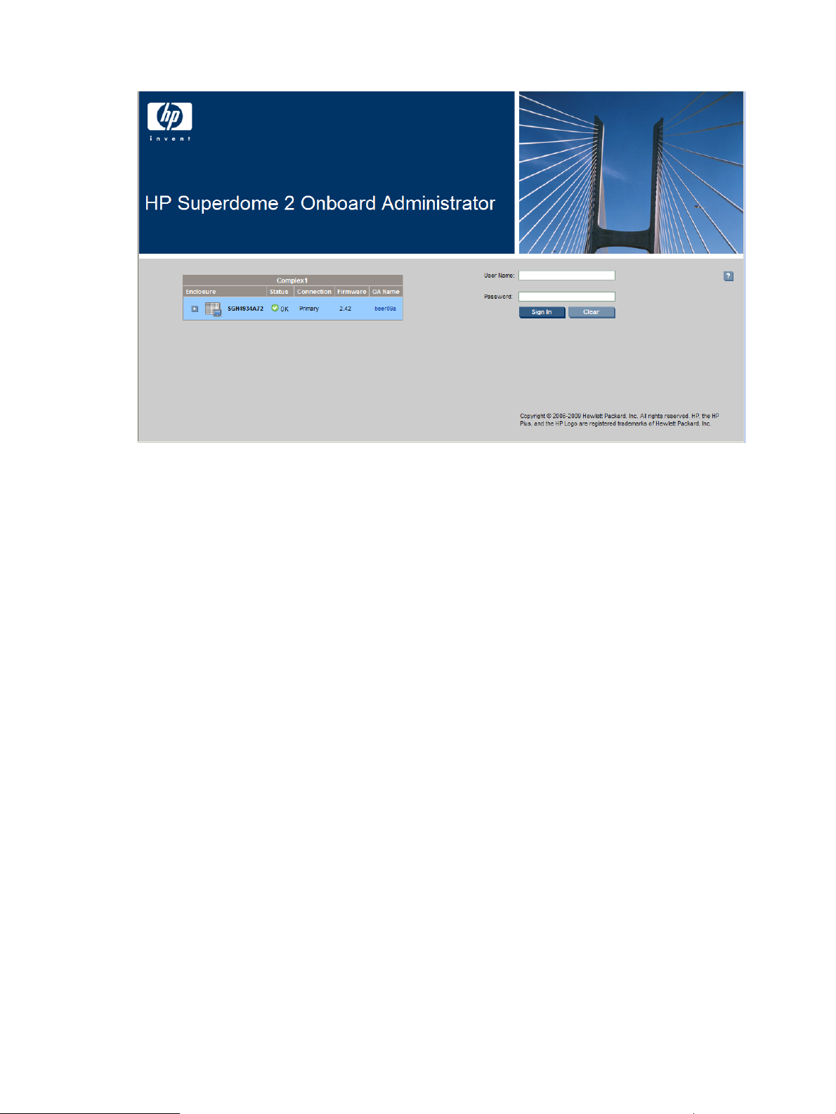
Logging on to the Onboard Administrator GUI
Enter the user name and initial administration password for your HP Superdome 2 Onboard
Administrator account found on the tag attached to the Onboard Administrator.
Possible issues that might occur when logging in include:
• Entering the information incorrectly. Passwords are case-sensitive.
• The account information entered not being set up for HP Superdome 2 Onboard Administrator.
• The user name entered has been deleted, disabled, or locked out.
• The password for the account requiring to be changed.
• Attempting to log on from an IP address that is not valid for the specified account.
• The password for the Administrator account being forgotten or lost. To reset the Administrator
password, see “Recovering the administrator password” (page 17).
If you continue to have problems signing in, contact your administrator.
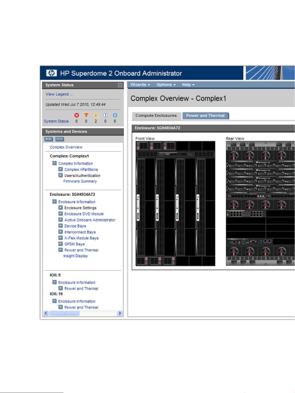
Running the setup wizard
To run the setup wizard, log on to Onboard Administrator. The First Time Setup Wizard starts
automatically when you log on to Onboard Administrator for the first time. This wizard assists you
in setting up the functions of the Onboard Administrator. You can access the setup wizard at any
time after initial setup by clicking the Wizards link on the top left of the center screen.
Logging on to the Onboard Administrator GUI 15
Page 16
For more information, see “First Time Setup Wizard” (page 41).
Using online help
To access online help, click the blue box with the white question mark located at the top right of
the screen under the header bar. Online help displays information related to the section of HP
Superdome 2 Onboard Administrator that you are navigating.
Changing enclosure and device configurations
After completing the First Time Setup Wizard, return to the Onboard Administrator GUI to make
configuration changes at any time. See “Configuring HP Integrity Superdome 2 compute enclosures
and enclosure devices” (page 79) for information that helps you make changes to enclosure and
device configuration, user setup, and LDAP server settings and LDAP groups.
See “Enclosure power management” (page 129) for information on enclosure power settings.
16 Introduction
Page 17

Recovering the administrator password
If the administrator password has been lost, you can reset the administrator password to the factory
default that shipped on the tag with the Onboard Administrator module. The Onboard Administrator
resets a lost password to Lost Password mode. To recover the password and reset the administrator
password to the factory default:
IMPORTANT: The password is recovered from the Monarch OA.
1. Connect a computer to the serial port of the active Onboard Administrator using a null-modem
cable.
2. With a null-modem cable (9600 N, 8, 1, VT100, locally connect to the Onboard Administrator),
open HyperTerminal (in Microsoft Windows) or a suitable terminal window (in Linux).
3. Connect to the active Onboard Administrator.
4. Press the Onboard Administrator reset button for 5 seconds.
5. Press L to boot the system in the Lost Password mode. The password appears as the system
reboots.
Recovering the administrator password 17
Page 18
2 HP Integrity Superdome 2 Insight Display
HP Integrity Superdome 2 Insight Display components
Insight Display overview
The Insight Display enables the rack technician to initially configure the enclosure. It also provides
information about the health and operation of the enclosure. The color of the Insight Display varies
with the condition of the enclosure health:
• Blue— The Insight Display illuminates blue when the enclosure UID is active.
The enclosure UID automatically turns on when the enclosure is powered on for the first time,
and can be turned on by selecting Turn Enclosure UID On from the Main Menu or by pressing
the enclosure UID button on the management interposer.
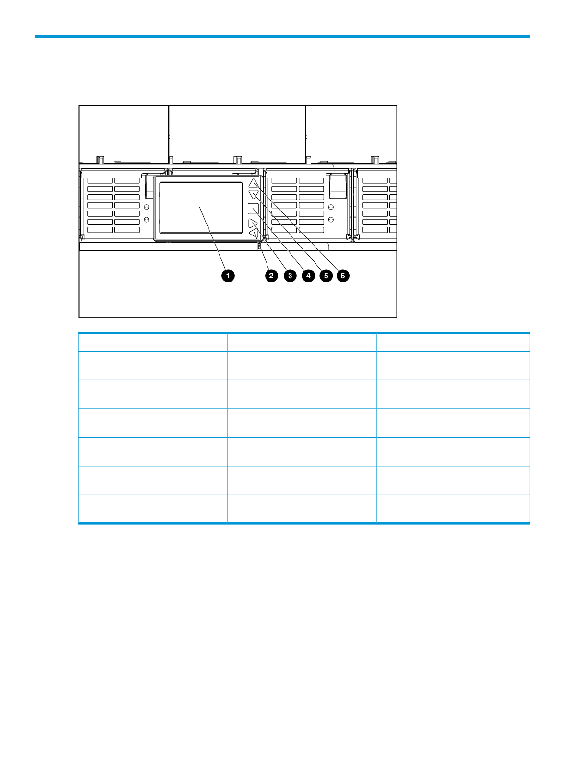
FunctionDescriptionItem
Insight Display screen1
Left arrow button2
Right arrow button3
OK button4
Down arrow button5
Up arrow button6
Displays Main Menu error messages
and instructions
Moves the menu or navigation bar
selection left one position
Moves the menu or navigation bar
selection right one position
Accepts the highlighted selection and
navigates to the selected menu
Moves the menu selection down one
position
Moves the menu selection up one
position
18 HP Integrity Superdome 2 Insight Display
Page 19

When the enclosure UID is on, the Insight Display flashes after two minutes of inactivity.
Pressing any button on the Insight Display stops the blinking and reactivates the screen.
• Green— The Insight Display illuminates green when no error or alert conditions exist, and the
enclosure is operating normally.
After two minutes of inactivity, the Insight Display light turns off. Pressing any button on the
Insight Display reactivates the screen.
• Amber— The Insight Display illuminates amber when the Onboard Administrator detects an
issue or alert condition. The screen displays the details of the condition.
After two minutes of inactivity, the Insight Display flashes amber indicating that an error or
alert condition exists. If the enclosure UID is on and an error or alert condition exists, the
Insight Display illuminates blue as the enclosure UID takes priority over the alert. Pressing any
button on the Insight Display reactivates the screen.
• Dark (no power)— The Insight Display has a two-minute inactivity period. If no action is taken
and no alert condition exists, the screen light turns off after two minutes. Pressing any button
on the Insight Display reactivates the screen.
The Enclosure Health icon is located at the bottom-left corner of every screen, indicating the condition
of the enclosure health. Navigate the cursor to the Enclosure Health icon and pressing OK to access
the Health Summary screen from any Insight Display screen.
Running the Insight Display installation
When the enclosure is powered on for the first time, the Insight Display launches an installation
wizard to guide you through the configuration process. After configuring the enclosure, the Insight
Display verifies that no installation or configuration errors are present. If errors are present, the
Insight Display guides you through the process of correcting the errors.
To identify the enclosure, the rear enclosure UID light and the background of the Insight Display
glow blue when the enclosure is powered on initially.
The Installation Wizard turns on the enclosure UID at the beginning of the installation and turns it
off after the installation is complete.
The Enclosure Settings screen is the first screen that appears. The background is blue, because the
enclosure UID is active when this screen appears.
1. Review each setting on the Enclosure Settings screen for accuracy.
2. To change any value, navigate the cursor to the menu option to be edited, and then press the
OK button.
3. Change the setting to the appropriate value, navigate the cursor to Accept, and then press
the OK button to return to the Enclosure Settings menu. Repeat this step until all options on the
Enclosure Settings menu are accurate.
Running the Insight Display installation 19
Page 20
TIP: Select the ? icon to access detailed help information about each setting or topic.
TIP: Within any menu option, navigate the cursor to What is This, and press the OK button
to view additional information about each setting, option, or alert.
4. When all settings on the Enclosure Settings menu are accurate, navigate the cursor to Accept
All, and then press the OK button to accept the current settings.
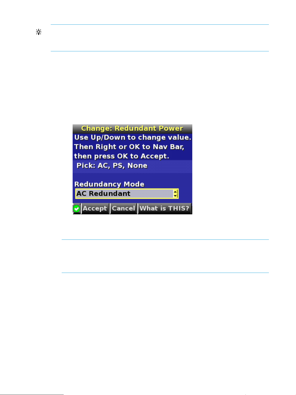
You can change the following options in the Enclosure Settings screen:
• Power Mode—The default setting is AC Redundant. The following selections are valid:
AC Redundant◦
◦ Power Supply Redundant
◦ None
• Power Limit—The default setting is Not Set. The Power Limit Watts ac setting can be
changed in increments of 50 Watts.
NOTE: When calculating the Power Limit Watts ac value, derate the circuit to 80% of
the maximum to prevent tripping the circuit breaker (United States only).
NOTE: If your facility cannot support the calculated peak Watts ac, set the Power Watts
ac value to match the capability of your facility.
• Dynamic Power —The default setting is Enabled. The following selections are valid:
Enabled —Some of the power supplies can be automatically placed on standby to
◦
increase overall enclosure power subsystem efficiency.
◦ Disabled —All power supplies share the load; the power subsystem efficiency varies
based on load.
• OA1 IP Addr— The default setting is DHCP; if no IP address is received, the IP address
is 0.0.0.0. The IP address, mask, and gateway are set within this option.
• OA2 IP Addr— If this module is present, the default setting is DHCP; if no IP address is
received, the IP address is 0.0.0.0. If only one Onboard Administrator module is installed,
the screen displays "Not Present."
20 HP Integrity Superdome 2 Insight Display
Page 21
• Enclosure Name— The default setting is a unique factory-assigned name. The accepted
character values are 0-9, A-Z ,a-z, -, _, and the box character. The box character is used
to signal the end of the name.
NOTE: Do not use the box character in the middle of a text box. Entries in text boxes
are truncated to the last character before the box character.
TIP: Select Clear from the navigation bar to quickly clear entries in text boxes up to the
symbol.
• Rack Name —The default setting is UnnamedRack. The accepted character values are
0-9, A-Z, a-z, -, _, and the box character. The box character is used to signal the end of
the name.
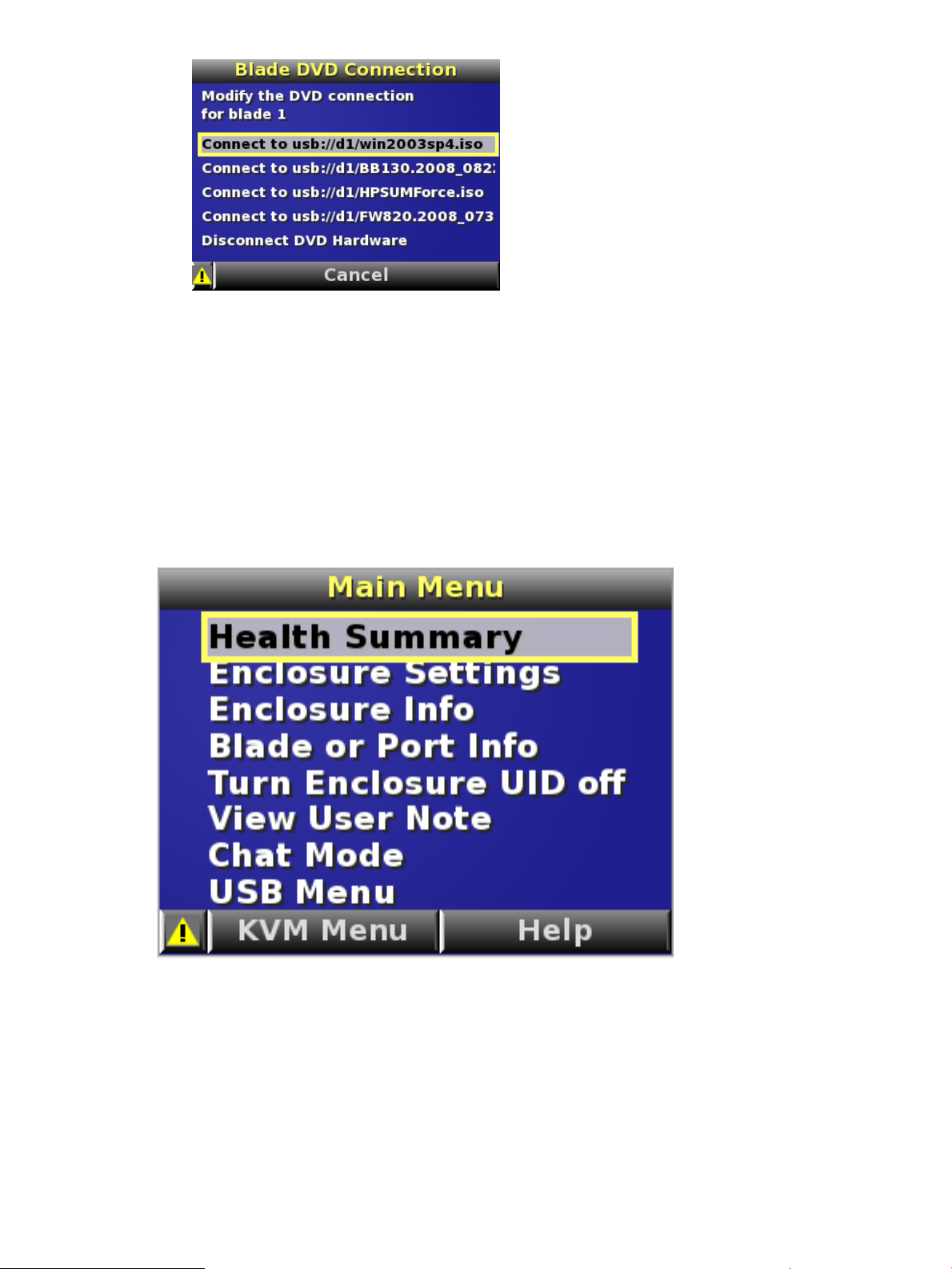
• DVD Drive— The DVD connection Settings screen is a table of all the servers with the
status of DVD Connection and blade name for that blade.
◦ Detach/Attach—Each blade can be individually attached to or detached from the
enclosure DVD drive by navigating to that bay and pressing the OK button.
◦ Change—Navigates to the Attach:Enclosure DVD menu where you can attach, attach
and reboot, or detach all bays from the DVD drive.
◦ Navigate to the DVD icon for a blade, and then press the OK button to change the
settings for an individual server.
◦ Navigate to All Blades, and then press OK to change the settings for all servers in
the enclosure.
◦ The server name is displayed next to each DVD icon limited to the first ten characters.
5. Navigate to the Accept All button at the bottom of the Enclosure Settings screen, and then
press the OK button to accept all the settings and continue.
The installation wizard displays the Check: Installation and Cables screen.
Running the Insight Display installation 21
Page 22
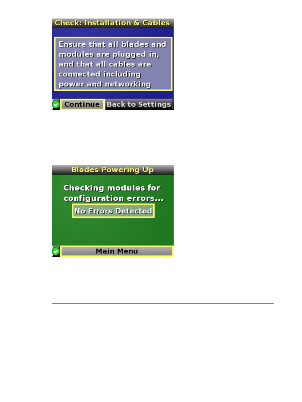
6. Be sure that all components are installed and cabled before continuing. Select Continue, and
press the OK button to begin verifying for configuration and installation errors. When Continue
is selected, the enclosure UID automatically turns off.
7. If no errors are detected, the rear enclosure UID turns off, and then the Insight Display screen
illuminates green. Press the OK button to return to the Main Menu. Enclosure and blade
hardware setup and configuration is complete.
If errors are detected, the Insight Display screen glows amber, and the Health Summary screen
appears. See “Insight Display errors” (page 30) for more information on troubleshooting
configuration and installation errors.
NOTE: Any configuration error prevents the operation of the enclosure and must be corrected
immediately.
8. Open a browser and connect to the active Onboard Administrator module using the Onboard
Administrator IP address that is configured during the Insight Display Installation Wizard
process.
9. Enter the user name and password from the tag supplied with the Onboard Administrator
module to access the remote Onboard Administrator web interface and complete the Onboard
Administrator First Time Installation Wizard.
22 HP Integrity Superdome 2 Insight Display
Page 23
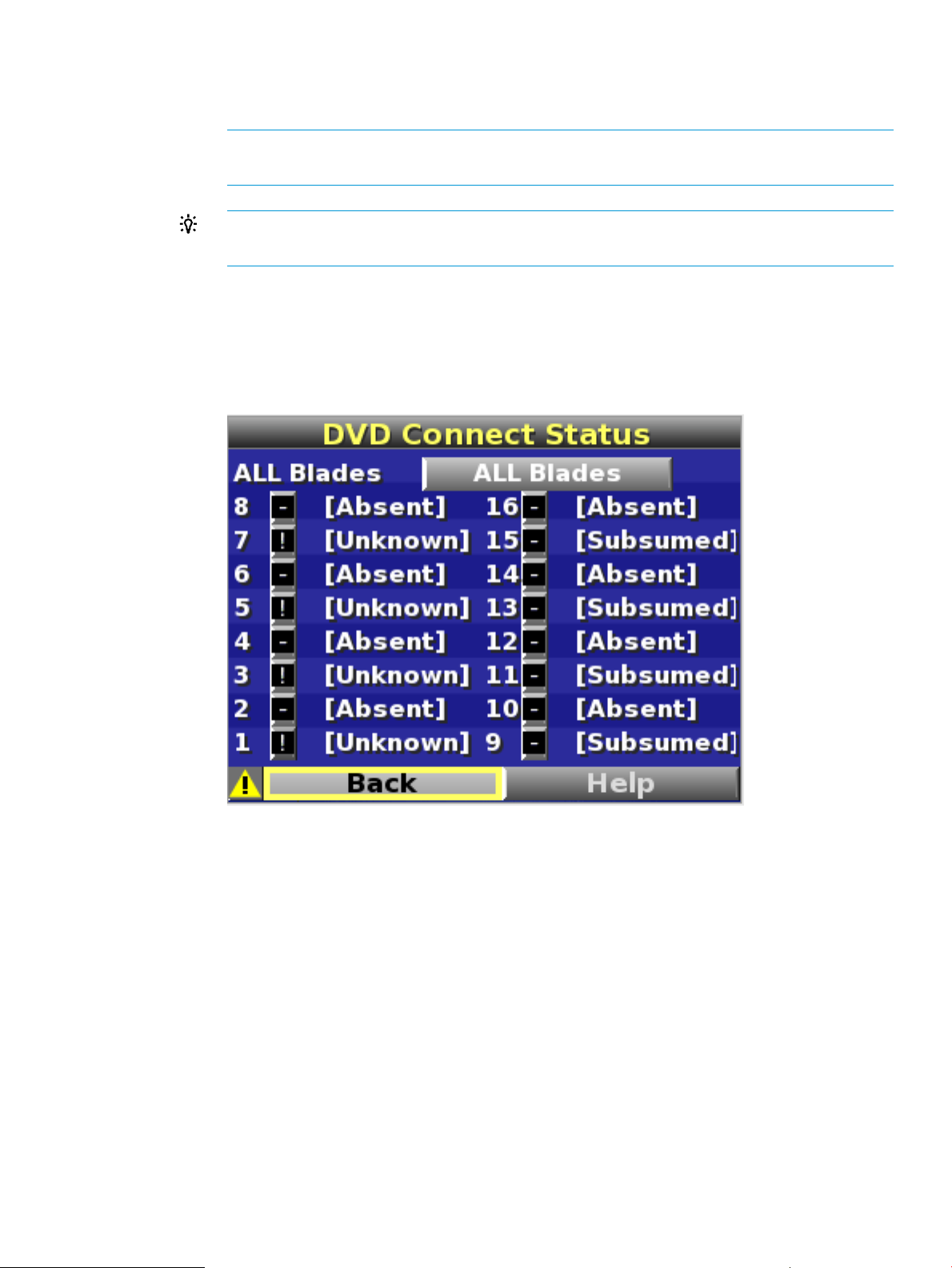
10. Navigate to Help, and then press OK to view the Help: DVD Connection screen.
• An exclamation icon indicates no DVD drive and disk is detected or firmware upgrade
is needed for this feature.
• A bright green DVD icon indicates the Enclosure DVD media is connected to the blade.
• A gray DVD icon indicates no DVD connection to that blade.
Navigating the Insight Display
Navigate the menus and selections by using the arrow buttons on the Insight Display panel.
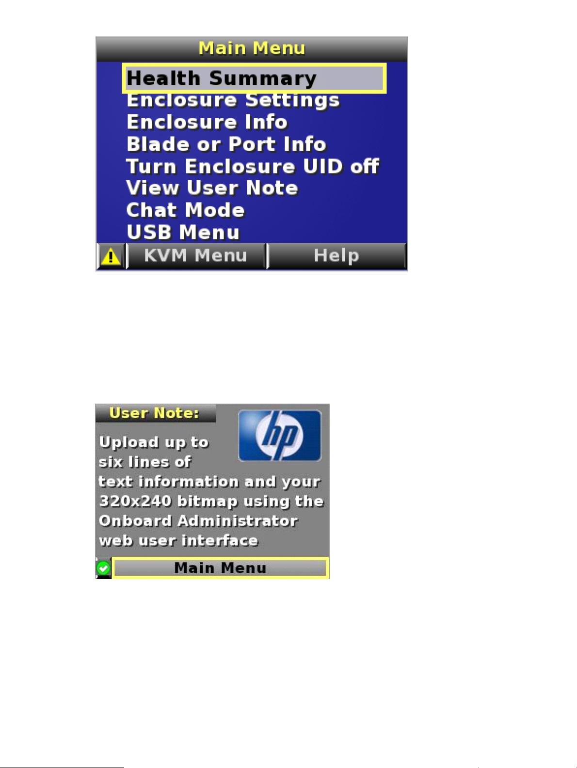
The first menu that appears is the Main Menu.
The Main Menu of the Insight Display has the following options:
• Health Summary
• Enclosure Settings
• Enclosure Info
• Blade or Port Info
• Turn Enclosure UID on/off
Navigating the Insight Display 23
Page 24
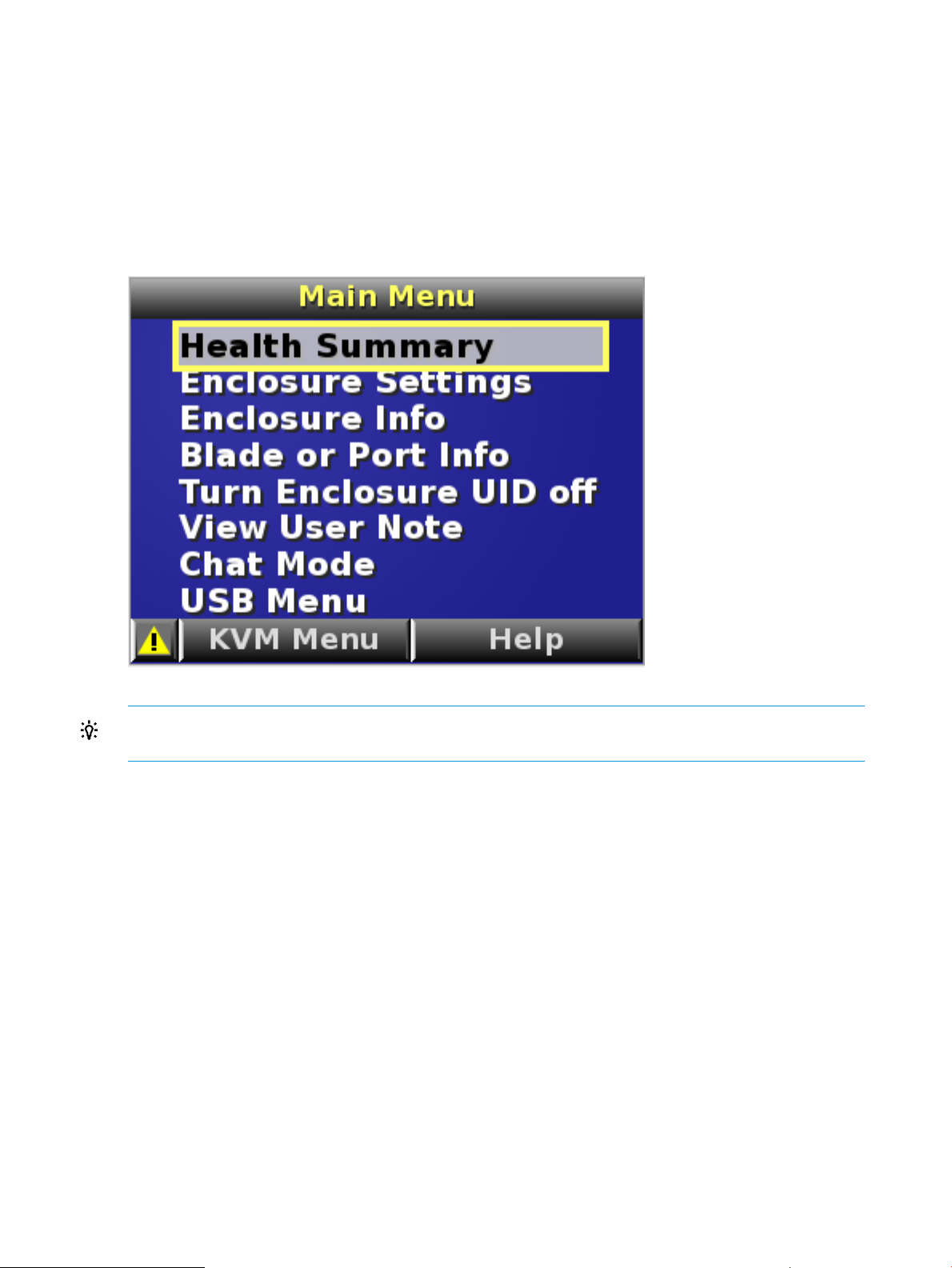
• View User Note
• Chat Mode
If the active Onboard Administrator detects a USB key drive with any *.ROM , *.CFG or *.ISO
files, then a USB menu item appears at the bottom of the Main Menu.
If the active Onboard Administrator detects KVM capability, a KVM menu button appears on the
navigation bar of the Main Menu. Selecting KVM Menu causes the Insight Display to go blank and
starts the VGA connection of Onboard Administrator.
A USB key drive with the appropriate files and KVM capability is present in the Main Menu:
TIP: Within any menu option, navigate the cursor to What is This, and press the OK button to
view additional information about each setting, option, or alert.
The navigation bar contains options to:
• Navigate forward and backward through alert screens
• Return to the main menu
• Accept changes to current settings
• Cancel changes to current settings
• Access the Health Summary screen from any screen by selecting the Health Summary icon on
the navigation bar
Health Summary screen
The Health Summary screen displays the current status of the enclosure. The Health Summary screen
can be accessed by:
• Selecting Health Summary from the Main Menu
• Selecting the Health Summary icon from any Insight Display screen
When an error or alert condition is detected, the Health Summary screen displays the total number
of error conditions and the error locations.
24 HP Integrity Superdome 2 Insight Display
Page 25

Select Next Alert from the navigation bar, and press the OK button to view each individual error
condition. The Insight Display displays each error condition in the order of severity. Critical alerts
display first (if one exists), followed by caution alerts.
When the enclosure is operating normally, the Health Summary screen displays green. The bright
green rectangles are components that are installed and are on. A light green rectangle represents
a component that is installed, but powered off with no errors.
When the enclosure is operating normally, the Health Summary screen displays green. The bright
green rectangles are components that are installed and on. A dark green rectangle represents a
component that is installed, but powered off with no errors. A black rectangle represents an empty
bay.
NOTE: A black DVD rectangle indicates no DVD drive is connected to the Onboard Administrator
while a dark gray rectangle indicates the DVD drive is present, but that no media is present. A
dark green rectangle indicates that media is present, but not actively connected to any server or
that all connected servers have issued a disk eject command, so the disk can be removed from the
drive. A bright green rectangle indicates that the media is present in the drive and actively connected
to at least one server in the enclosure, and the drive tray is locked.
If an error occurs, the Health Summary screen background changes from green to amber and the
error is highlighted with yellow rectangles for caution and red rectangles for failures. Overall
enclosure health icons at the bottom-left corner of the Insight Display screens indicate the overall
enclosure health.
To display the errors, select View Alert and then press the OK button.
To view the details of the error, select Details.
Enclosure Settings screen
The Enclosure Settings screen displays the following setting information about the enclosure:
• Power Mode setting
• Power Limit setting
• Dynamic Power setting
• Active and Standby OA IP addresses
Navigating the Insight Display 25
Page 26
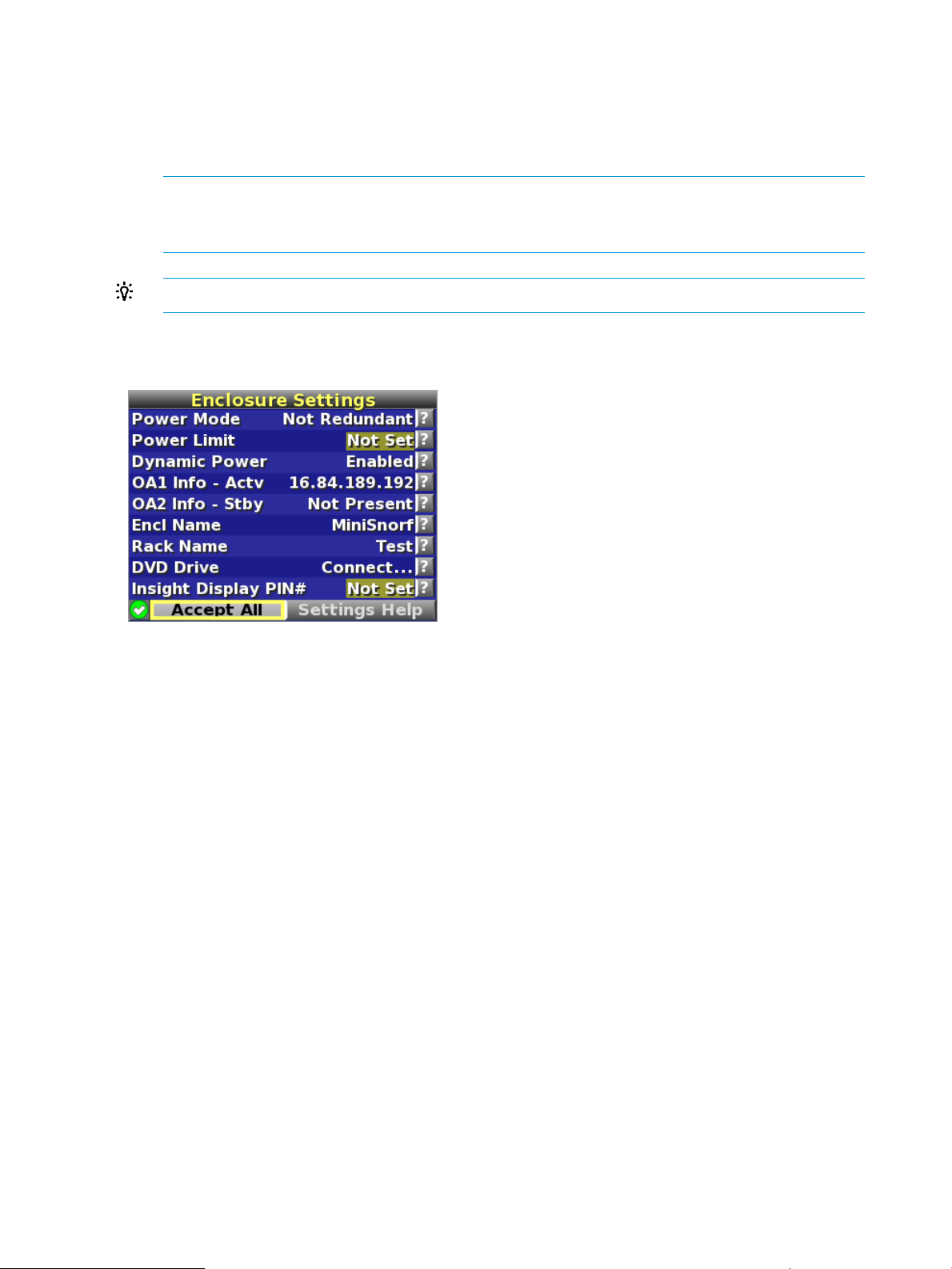
• Enclosure Name
• Rack Name
• DVD Drive
• Insight Display PIN#
NOTE: The DVD Drive setting can attach or detach a CD or DVD loaded in the DVD drive
to any or all partitions in the enclosure. This feature can be used to install an operating system
or software on the partitions.
TIP: To protect the enclosure settings from changes, set a PIN.
To change the setting or get help for a setting, navigate the cursor to that setting or to ?, and press
OK.
Enclosure Info screen
The Enclosure Info screen displays information about the enclosure, including:
• Active OA IP address
• Active OA Service IP address
• Current health status of the enclosure
• Current enclosure ambient temperature
• Current ac input power to the enclosure
• Enclosure name
• Rack name
26 HP Integrity Superdome 2 Insight Display
Page 27
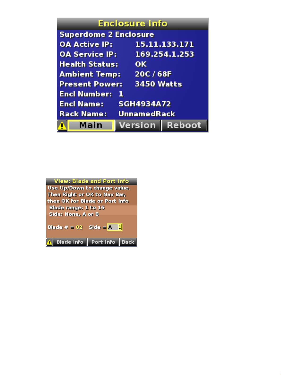
Blade and Port Info screen
The Blade and Port Info screen displays information about a specific server blade. On the first
screen, select the server blade number, and then press the OK button. Select Blade Info or Port
Info, and then press the OK button.
To view information about the server blade, select Blade Info, and then press the OK button.
Navigating the Insight Display 27
Page 28
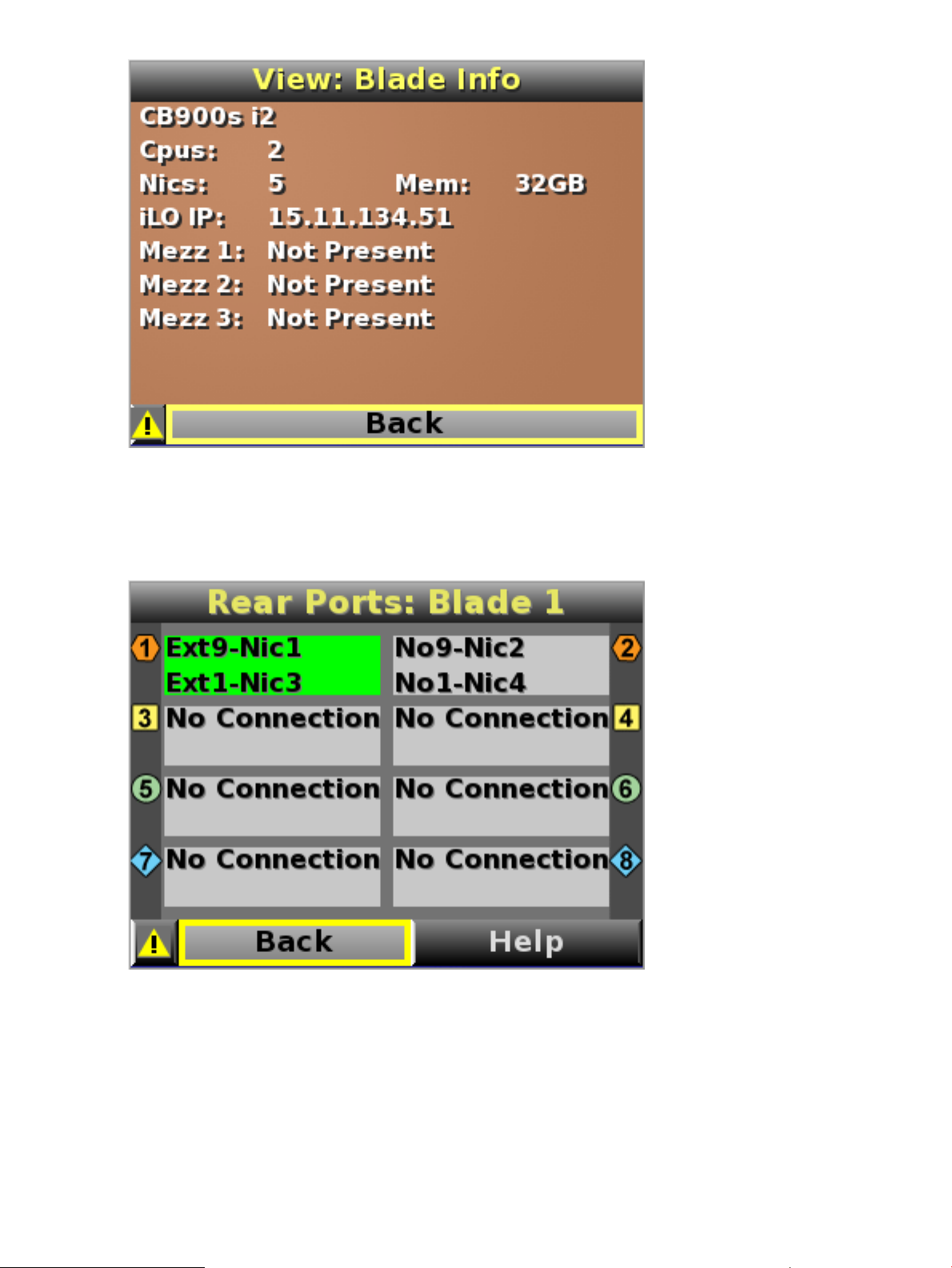
To view the ports used by a specific server blade, select Port Info, and then press the OK button.
The following screen shows a server blade with four embedded NICs. The other interconnect bays
are empty. The four embedded NICs are connected to particular port numbers on the interconnect
modules.
Turn Enclosure UID On/Off screen
The Main Menu displays Turn Enclosure UID Off when the enclosure UID is active, and displays
Turn Enclosure UID on when the enclosure UID is off.
Selecting Turn Enclosure UID On from the main menu turns on the rear enclosure UID LED and
changes the color of the Insight Display screen to blue.
28 HP Integrity Superdome 2 Insight Display
Page 29
Selecting Turn Enclosure UID Off from the main menu turns off the rear enclosure UID LED and
changes the color of the Insight Display screen to the current alert condition.
View User Note screen
The View User Note screen displays six lines of text, each containing a maximum of 16 characters.
Use this screen to display helpful information such as contact phone numbers. Change this screen
using the remote Onboard Administrator user web interface. Both the background bitmap and the
text can be changed.
Chat Mode screen
The Chat Mode screen is used by the remote administrator who uses the web interface to send a
message to an enclosure Insight Display. The technician uses the Insight Display buttons to select
from a set of prepared responses, or dials in a custom response message on the ? line. To send a
response back to the Administrator, navigate the cursor to Send, then press the OK button.
The Chat Mode screen has top priority in the Insight Display and remains on the screen until you
select Send. The technician can leave this chat screen temporarily and use the other Insight Display
screens, then return to the Chat Mode screen from the Main Menu to send a response. After the
response, the Chat Mode screen is cleared. Both the A and ? responses appear to the remote
Administrator on the LCD Chat web interface.
Navigating the Insight Display 29
Page 30

Insight Display errors
The enclosure installation is successful when all errors are corrected. The errors in the following
sections are specific to installation and initial configuration of the enclosure.
The following types of errors might occur when installing and configuring the enclosure:
• Power errors
• Cooling errors
• Location errors
• Configuration errors
• Device failure errors
When the enclosure UID LED is off, the Insight Display is illuminated amber when any error condition
exists. The navigation bar displays the following selections when an error condition exists:
• Health summary icon— Displays the Health Summary screen
• Fix This— Suggests corrective action to clear the current error
• Next Alert— Displays the next alert, or if none exist, displays the Health Summary screen
• Previous Alert— Displays the previous alert
Power errors
Power errors can occur because of insufficient power to bring up an enclosure. Power errors can
occur on server blades, storage blades, or interconnect modules.
To correct a power error:
1. Use the arrow buttons to navigate to Fix This, and then press OK.
2. Review and complete the corrective action suggested by the Insight Display. In most cases,
you must either add power supplies to the enclosure or remove the indicated components.
Cooling errors
Cooling errors occur when too few fans are installed in the enclosure or when the existing fans
are not installed in an effective configuration. Cooling errors can occur on server blades, storage
blades, or interconnect modules.
To correct a cooling error:
30 HP Integrity Superdome 2 Insight Display
Page 31

1. Use the arrow buttons to navigate to Fix This, and press OK.
2. Review and complete the corrective action suggested by the Insight Display. In most cases,
you must either add fans to the enclosure, correct the fan configuration, or remove the indicated
components.
Location errors
Location (installation) errors occur when the component is not installed in the appropriate bay.
Location errors can occur on server blades, storage blades, power supplies, and fans.
To correct a location error:
1. Use the arrow buttons to navigate to Fix This, and press OK.
2. Review and complete the corrective action suggested by the Insight Display. Remove the
indicated component, and install it into the correct bay. The Insight Display will indicate the
correct bay number.
Configuration errors
Configuration errors can occur if the interconnect modules are installed in the wrong bays or if
mezzanine cards are installed in the wrong connectors in the server blade. Configuration errors
can occur on server blades and interconnect modules.
To correct a configuration error:
1. Use the arrow buttons to navigate to Fix This, and press OK.
2. Review and complete the corrective action suggested by the Insight Display. Depending on
the error received, do one of the following:
• Remove the indicated interconnect module, and install it into the correct bay. (The Insight
Display indicates the correct bay.)
• Remove the server blade to correct the mezzanine card installation. (The Insight Display
indicates the correct bay.) For information on installing the mezzanine card, see the
server-specific user guide on the Documentation CD.
Device failure errors
Device failure errors occur when a component has failed. Device failure errors can occur on all
components, including:
• Server blades
• Storage blades
• Power supplies
• Interconnect modules
• Onboard Administrator modules
• Fans
• ac power inputs
To correct a device failure error:
1. Use the arrow buttons to navigate to Fix This, and press OK.
2. Review and complete the corrective action suggested by the Insight Display. In most cases,
you must remove the failed component to clear the error.
3. Replace the failed component with a spare, if applicable.
NOTE: If the device failure error is an ac power input failure error, then to clear the error,
you must have the failed ac input repaired.
Insight Display errors 31
Page 32

3 HP Superdome 2 Door Status Display
HP Superdome 2 SD2-16s and SD2-32s complexes that are factory integrated ship with the HP
Superdome 2 Door Status Display. The Door Display is a quick method of getting basic complex
status information by using the integrated touch screen on the rack door.
NOTE: HP Superdome 2 SD2-8s complexes do not support the Door Display.
The Door Display screen and LED backlighting displays the overall status of the complex by the
following scheme:
• Solid blue—The Door Display screen and LED backlight glows solid blue when the complex
is operating under normal conditions.
• Flashing blue—The Door Display screen and LED backlight flashes blue when the enclosure
UID of any compute enclosure in the rack is turned on.
• Flashing amber—The Door Display and LED backlight flashes amber if any compute enclosure
in the rack has an error or alert condition.
If an enclosure UID is on and an error or alert condition exists, the Door Display and LED
backlight flashes blue as the enclosure UID takes priority over the alert.
• Dark (no power)—The Door Display screen turns off after one hour of displaying a screen
saver. Touch the Door Display screen to return to the last menu displayed. The LED backlight
remains glowing to reflect the current complex status.
NOTE: You can only disable the Door Display screen by using the Door Display menu. You
cannot disable the screen remotely.
After one hour of inactivity, the Door Display screen displays a screen saver. Touch the Door
Display screen to return to the last menu that was onscreen.
Before running Door Display setup
Before running the Door Display setup, you must create Onboard Administrator accounts. The Door
Display uses the Onboard Administrator accounts to access complex information and enables you
to set the enclosure UID for compute enclosures in the rack.
Setting up the Door Display
When the complex is first powered on, a brief animation on the Door Display screen is displayed,
and then the startup menu appears.
NOTE: The startup menu will take several seconds to appear while the Door Display starts up.
32 HP Superdome 2 Door Status Display
Page 33

The startup menu has the following options:
• Disable Display—A screen saver immediately appears for one hour, and then the Door Display
shuts off.
• Setup—Select this option to begin the Door Display setup.
Complex configuration
Select the current complex configuration in the rack.
Setting up the Door Display 33
Page 34

IMPORTANT: This menu selection does not set the complex configuration on the Onboard
Administrator. To correctly set up the Door display, you must select the current complex configuration
present in the rack.
Press Next.
Status display preferences
• Temperature Scale—Select between displaying enclosure temperatures in °C or °F.
• Display IP Address—Select to enable or disable the display of the IP addresses of the active
Onboard Administrator and the complex service port.
NOTE: The OA IP address does not appear until the setup process is complete.
Press Next to continue.
Two 16s complex setup
If the complex configuration is 2 16s complexes in a Cabinet, unlike the other multi-enclosure
configurations, each enclosure is a self-contained complex and each will require its own login and
password information.
34 HP Superdome 2 Door Status Display
Page 35

If you selected Two 16s as the complex configuration, then you are prompted to which complex
displays status information on the Door Display screen.
• Lower Complex—The Door Display screen displays status information for only the lower
SD2-16s complex in the rack.
• Upper Complex—The Door Display screen displays status information for only the upper
SD2-16s complex in the rack.
• Both Complexes—The Door Display screen displays status information for both SD2-16s
complexes in the rack.
NOTE: If you select Both Complexes, you are prompted to enter two user names and
passwords at the next menu.
Press Next.
Setting up the Door Display 35
Page 36

Complex login
You must enter an OA account user name and password to enable the Door Display to log in to
the complex and display complex status information.
IMPORTANT: If you enter an OA Administrator or OA Operator-level user name, all complex
information appears and the Door Display screen can be used to set the enclosure UID.
If you enter an OA User-level user name, all complex information appears, but the Door Display
screen cannot be used to set the enclosure UID.
Press Login to complete setup or Cancel to quit Door Display setup.
Door Display status menu
36 HP Superdome 2 Door Status Display
Page 37

The Door Display status menu displays the following information:
• Complex name—The user-specified name of the complex.
• Complex health—The current health status of the complex.
If there is an enclosure in the complex that now has fault conditions, the enclosure will be
highlighted amber and indicated with a fault symbol.
• Active (OA) IP address—The IP address of the active Onboard Administrator.
• Service IP address—The IP address of the complex service port.
• Enclosure power—The current power consumption of the enclosures in the complex in kW.
• Enclosure temperature—The current temperature of the enclosures in the complex in °C or °F.
• Enclosure UID—If an enclosure in the complex has the enclosure UID enabled, then the enclosure
will be indicated with a UID symbol.
The Door Display status menu has the following menu buttons:
• Display Settings—Display the Display Settings menu.
• UID—Display the UID control overlay.
If the rack contains two SD2-16s complexes, then the Door Display status menu displays the following
buttons:
• Upper Complex— Displays the status of the upper complex in the rack.
• Lower Complex— Displays the status of the lower complex in the rack.
• Logon— If the OA log on information is not specified for an enclosure in the rack, select this
option to enter the OA log on information.
UID control
To change the UID of enclosures in the rack, push the On/Off toggle button for the enclosures.
Press Confirm to turn the enclosure UIDs on or off and return to the Door Display status menu. To
return to the Door Display status menu without making any changes, press Cancel.
Setting up the Door Display 37
Page 38

Display Settings menu
IMPORTANT: Accessing the Display Settings screen requires a valid door display login even if
no settings are changed. If you cancel out of the Display Settings without entering the correct login
information, the door display will continue to show the “Login and Setup Info is required" message.
The Display Settings menu has the following options:
• Door Display Setup— Runs the initial setup of the Door Display.
• Disable Display— Erases all settings. A screen saver immediately appears for one hour, and
then the Door Display shuts off.
IMPORTANT: If you select this option, you must re-enter all setting information, such as user
names and passwords before you can use the Door Display.
• Calibrate Screen— Enters calibration mode for the touch screen.
IMPORTANT: HP recommends using a stylus or the back of a pencil to calibrate the screen.
Using a finger is not precise enough to properly calibrate the screen.
Do not use metal objects to calibrate the screen. Using a metal object might damage the LCD
touch screen.
• Firmware Update— Use this option to update the Door Display firmware. The current status
of the Door Display firmware is displayed on the menu button. The firmware status is one of
the following:
◦ Setup required first— The initial Door Display setup has not been completed and the Door
Display is unable to access firmware status.
◦ Up-to-date— The current Door Display firmware matches the current revision available
on the OA. No firmware update is required. If necessary, the Door Display firmware can
be reloaded using the Firmware Update menu.
38 HP Superdome 2 Door Status Display
Page 39

◦ Update Available— A newer firmware revision is available for the Door Display.
◦ No Update Available— The OA does not have firmware available for the Door Display.
This occurs if the OA web server is disabled.
NOTE: The Door Display firmware must be updated through the Door Display menu.
• Reboot Display— Restarts the Door Display module only.
IMPORTANT: You must reboot the Door Display after the Onboard Administrator reboots.
The Door Display does not function until you reboot the Door Display after the Onboard
Administrator reboots.
Press Exit Display Settings to return to the Door Display status menu.
Firmware Update menu
NOTE: This menu is used to update the firmware of the Door Display only.
The Firmware Update menu is available if the firmware status is displayed as Up-to-date or Update
Available on the Firmware Update menu option.
Choose one of the following options:
• To begin the firmware update process, press Start.
• To return to the Display Settings menu without updating the firmware, press Exit Firmware
Update.
NOTE: If the versions of the current Door Display firmware and the firmware available on the
OA match, you are prompted to reload the firmware or cancel.
Setting up the Door Display 39
Page 40

When the firmware update is complete, you are prompted to reboot the Door Display to complete
the firmware update. To reboot the Door Display only, press Reboot. After the Door Display reboots,
you are prompted to calibrate the LCD touch screen.
If you do not want to reboot the Door Display, press Not Now. The firmware update is not complete
until the Door Display is rebooted.
40 HP Superdome 2 Door Status Display
Page 41

4 First Time Setup Wizard
NOTE: The First Time Setup Wizard is used only to configure compute enclosures and Onboard
Administrator network settings. The First Time Setup Wizard does not enable you to set up and
configure partitions.
For information on partition creation and management, see the HP Integrity Superdome 2 Partitioning
Administrator Guide.
Before you begin
Before running the First Time Setup Wizard, complete the following tasks:
1. Install the Onboard Administrator modules.
2. Connect the Onboard Administrator modules to the network.
3. Complete the Insight Display installation wizard. You must at least configure the active Onboard
Administrator IP address.
4. Run the Insight Display installation.
Logging on to Onboard Administrator
For information on logging on to the Onboard Administrator, see “Logging on to the Onboard
Administrator GUI” (page 15).
The first time you log on, the Onboard Administrator automatically runs the First Time Setup Wizard.
To navigate the setup wizard, click the Next button to save your changes and go to the next step.
Click the Skip button if you want to leave the step without saving the changes.
You can return to previous wizard steps by selecting them in the left tree view. You can also run
the wizard again at any time by selecting it from the Wizards menu.
Enclosure Selection screen
The Enclosure Selection screen displays all discovered enclosures and selects the active enclosure,
the enclosure you are signed in to by default. The check box beside each enclosure enables you
to select or clear that enclosure. Selecting the check box beside All Enclosures toggles the check
box for all enclosures.
Click the Refresh Topology button to update the rack topology information. When you select Refresh
Topology, the Enclosure Selection screen switches to the Linked Mode and all linked enclosures
appear.
Before you begin 41
Page 42

If more than one enclosure is listed on the Enclosure Selection screen, select the enclosure you want
to set up, and then click the Next button.
For possible values and descriptions of each box, see “Enclosure Settings screen” (page 80).
Configuration Management screen
The Configuration Management screen enables you to set up the selected enclosures using a
configuration file saved from a previous setup. You can run scripts for multiple Onboard
Administrators before leaving the current screen.
To set up selected enclosures, using a configuration file:
42 First Time Setup Wizard
Page 43

On the Configuration Management screen, select one of the following options:
• Local file: Browse for the configuration file, or enter the path of the script file into the textbox.
The maximum number of characters in the file path is 256. Click Upload after entering the
script file path.
• URL: Enter an http:// path to the configuration file if it is located on a web server. The maximum
number of characters in the file path is 256. Click Upload after entering the URL. A window
opens and displays the results.
If more than one enclosure is selected during the enclosure selection, select the enclosure to upload
or apply the configuration file to use from the drop-down that appears. If multiple enclosures were
selected, then repeat this process for each additional enclosure. You cannot select more than one
enclosure at a time for configuration management.
Rack and Enclosure Settings screen
This screen enables you to assign time settings and a common name to your rack and to assign
unique names and asset tags to your enclosures.
Rack Name
1 to 32 characters including all alphanumeric
characters, the dash (-), and the underscore (_)
• mm is an integer from 1 to 12
• dd is an integer from 1 to 31
• hh is an integer from 0 to 23
• mm is an integer from 0 to 59
• ss is an integer from 0 to 59
DescriptionPossible valueBox
The name of the rack in which the
enclosure is installed
The current date assigned to the enclosureyyyy-mm-dd, where:Date
The current time assigned to the enclosurehh:mm:ss (24-hour time)Time
Rack and Enclosure Settings screen 43
Page 44

DescriptionPossible valueBox
###.###.###.### where ### ranges from 0 to 255Primary NTP Server
###.###.###.### where ### ranges from 0 to 255Secondary NTP
Server
• “Africa time zone settings” (page 190)
• “Americas time zone settings” (page 190)
• “Asia time zone settings” (page 192)
• “Universal time zone settings” (page 192)
• “Oceanic time zone settings” (page 193)
• “Europe time zone settings” (page 193)
• “Polar time zone settings” (page 194)
Enclosure Name
characters, the dash (-), and the underscore (_)
Asset Tag
0 to 32 characters including all alphanumeric
characters, the dash (-), and the underscore (_)
See the HP Integrity Superdome 2 User Service Guide for more information on connecting enclosures.
Administrator Account Setup screen
IP address of primary NTP server that
provides date and time information
IP address of secondary NTP server that
provides date and time information
The time zone assigned to the enclosureTime zone settingsTime Zone
The name of the selected enclosure1 to 32 characters including all alphanumeric
The asset tag is used for inventory control.
The default asset tag is blank.
The Administrator Account Setup screen initially displays the name of the active enclosure and its
current settings. If multiple enclosures are selected on the Enclosure Selection screen, a button is
activated that enables you to expose separate inputs for each selected Onboard Administrator.
44 First Time Setup Wizard
Page 45

DescriptionPossible valueBox
Password
Password Confirm
Full Name
Contact
PIN Code
PIN Code Confirm
Local User Accounts screen
The Local User Accounts screen displays the user accounts assigned to the Active Onboard
Administrator and provides choices for adding, editing, and deleting accounts.
3 to 8 characters including all
printable characters
printable characters
alphanumeric characters, the dash (-),
the underscore (_), and the space
0 to 20 characters including all
alphanumeric characters, the dash (-),
the underscore (_), and the space
1 to 6 characters from the character
sets 0 to 9, a to z, and A to Z
1 to 6 characters from the character
sets 0 to 9, a to z, and A to Z
The password for the Administrator
account
Must match the Password value3 to 8 characters including all
The full name of the user0 to 20 characters including all
Contact information for the user
account. The contact information can
be the name of an individual, a
telephone number, or other useful
information.
The PIN code for the enclosure Insight
Display
Must match the Insight Display PIN
value
Local User Accounts screen 45
Page 46

• New: Click the New button to add a new user to the selected enclosure. A maximum of 30
user accounts can be added including the reserved accounts. The Add Local User screen
appears.
• Edit: Select a user (only one can be selected) by selecting the check box next to the name of
the user. Click the Edit button to change the settings on the Edit Local User screen.
• Delete: Select a user or users to be deleted by selecting the check box next to the name of the
user. Click the Delete button to delete the accounts. If an attempt is made to delete the last
Administrator account, you will receive an alert warning that at least one Administrator account
must exist and the delete action is canceled.
User Settings screen
The User Settings screen displays configurable user information.
1. Enter user information in the User Information and User Permissions sections.
2. Click Add User or Update User to save the information.
3. To return to the Local User Accounts screen, click Cancel.
4. For each user added, select the appropriate boxes to grant access to servers and interconnect
bays. For possible values and descriptions of each box, see “Managing users” (page 140).
46 First Time Setup Wizard
Page 47

Enclosure Bay IP Addressing screen
The Onboard Administrator EBIPA feature is intended to help you provision a fixed IP address to
a particular bay in an enclosure. The components plugged into the bays are set for DHCP, and
interconnect modules are configured to use the internal management port to Onboard Administrator.
If the component is configured for a static IP address, an EBIPA assignment to that bay has no
effect.
NOTE:
If you use DHCP servers on your management network, then do not use EBIPA for management IP
address assignments.
If you use static IP addresses for management processors, Onboard Administrator CLI hponcfg
command can be used with HP ProLiant server blades to send the iLO network settings RIBCL script
to an iLO if that iLO already has an IP address. EBIPA can be used to bootstrap IP addresses to
iLOs, so that Onboard Administrator CLI hponcfg command can be used to send configuration
scripts to those iLOs. Changes to iLO network settings results in that iLO resetting its network and
breaking the current connections for a few seconds.
If the server blade is configured for static IP address, then it carries the same address even if the
blade is moved to another enclosure.
If the server blades are set for DHCP and the Onboard Administrator is configured for EBIPA for
that bay, then iLO gets an EBIPA-configured IP address when it is plugged into that enclosure.
If your network has an external DHCP service or if you want to manually assign static IP addresses
one by one to the server blades and interconnect modules, then to bypass this step, click the Skip
button.
Enclosure Bay IP Addressing screen 47
Page 48

EBIPA Settings screen
For information on how to set up EBIPA, see (page 91).
Directory Groups screen
LDAP is an open protocol for accessing information directories. While LDAP is based on the X.500
standard, it is significantly simpler. LDAP supports TCP/IP, which enables applications to work
independently of the server hosting the directory.
Use the Directory Group screen to set directory access for the now selected enclosures.
48 First Time Setup Wizard
Page 49

On this screen, you can configure directory groups.
For possible values and descriptions of each box, see “Directory Groups” (page 149).
Directory Settings screen
Use the Directory Settings screen to set directory access for the now selected enclosures.
Using the Directory Settings screen, you can configure the following settings:
• Enable LDAP Authentication: Enables a directory server to authenticate a user login.
• Enable Local Users: Enables a user to log on using a local user account instead of a directory
account.
DescriptionPossible valueBox
Directory Server Address
Search Context 1
Search Context 2
Search Context 3
###.###.###.### where ### ranges
from 0 to 255 or DNS name of the
directory server or the name of the domain
0 to xxxxDirectory Server SSL Port
All characters except " (quotes), not to
exceed 128 characters
All characters except " (quotes), not to
exceed 128 characters
All characters except " (quotes), not to
exceed 128 characters
The IP address or the DNS name or the
name of the domain of the directory service
The port used for LDAP communications.
The default port is port 636
First searchable path used to locate the user
when the user is trying to authenticate using
directory services
Second searchable path used to locate the
user when the user is trying to authenticate
using directory services
Third searchable path used to locate the
user when the user is trying to authenticate
using directory services
• Use NT Account Name Mapping (DOMAIN\username): Enables NT name mapping so that
you can enter the NT domain and user name.
Directory Settings screen 49
Page 50

Onboard Administrator Network Settings screen
Use the Onboard Administrator Network Settings screen to modify network settings for all the
Onboard Administrator modules in the selected enclosures. Settings for Standby Onboard
Administrator modules appear only if the modules are present. Options for DHCP and static IP are
supported.
• Use DHCP for all Active Onboard Administrators: Get the IP address for the Onboard
Administrator from a DHCP server. The Standby check box is shown only if there is a Standby
Onboard Administrator in the enclosure.
• Enable Dynamic DNS: Enable using a DNS server to translate host names into IP addresses
when using DHCP.
• Use static IP settings for each Active Onboard Administrators: Manually set up static IP settings
for the Onboard Administrator. The Standby check box is shown only if there is a Standby
Onboard Administrator in the enclosure.
For possible values and descriptions of each box, see “TCP/IP Settings screen” (page 101).
SNMP Settings screen
Use the SNMP Settings screen to configure or modify the SNMP settings for the active HP Superdome
2 Onboard Administrator.
50 First Time Setup Wizard
Page 51

For possible values and descriptions of each box, see “SNMP Settings screen” (page 94).
Power Management screen
IMPORTANT: In a complex with one or more failed power supplies, it is possible for attempts to
power on servers to fail if the resulting power allocation would result in the Power Redundancy
Status becoming Failed. The administrator must explicitly reduce the redundancy setting to enable
powering on servers prior to the failed power supplies being serviced. This applies to AC Redundant
and Power Supply Redundant power modes.
NOTE: If redundancy mode is set to Redundant, AC Redundant, or Power Supply Redundant,
and power redundancy is lost, then you must either add additional power supplies or change the
redundancy mode setting in the Onboard Administrator to restore Power Subsystem status. One
upper and one lower power supply must always be installed and operational. For corrective steps,
see the Insight Display.
Power Management screen 51
Page 52

The Superdome 2 enclosure power management system enables you to customize the configuration
of the enclosure. You can select from the various modes on the Onboard Administrator Power
Management screen. The power modes are explained in the following table.
DescriptionInsight Display nameMode
52 First Time Setup Wizard
RedundantRedundant
AC RedundantAC Redundant
For dc power supplies only. In this configuration, N upper and N
lower power supplies are used to provide power and N upper and
N lower power supplies are used to provide redundancy (where N
can equal 1, 2, or 3). Up to three upper and three lower power
supplies can fail without causing the enclosure to fail. When correctly
wired with redundant dc line feeds, this configuration also ensures
that a dc line feed failure does not cause the enclosure to power off.
For ac power supplies only. In this configuration, N upper and N
lower power supplies are used to provide power and N upper and
N lower power supplies are used to provide redundancy (where N
can equal 1, 2, or 3). Up to three upper and three lower power
supplies can fail without causing the enclosure to fail. When correctly
wired with redundant ac line feeds, this configuration also ensures
Page 53

DescriptionInsight Display nameMode
that an ac line feed failure does not cause the enclosure to power
off.
Power SupplyPower Supply
Redundant
NoneNot Redundant
Dynamic PowerDynamic Power
Power LimitPower Limit
Up to six upper and six lower power supplies can be installed with
one upper and one lower power supply always reserved to provide
redundancy. In the event of a single upper or lower power supply
failure, the redundant power supply in the same section (upper or
lower) takes over the load. A line feed failure of more than one
power supply in a section causes the system to power off.
There is no power redundancy and no power redundancy warnings
are given. If all power supplies are needed to supply Present Power,
then any power supply or line failure can cause the enclosure to
power off.
If enabled, Dynamic Power automatically places unused power
supplies in standby mode to increase enclosure power supply
efficiency, thereby minimizing enclosure power consumption during
lower power demand. Increased power demands automatically
return standby power supplies to full performance. This mode is not
supported for low voltage on the Superdome 2 enclosure.
An optional setting to limit power. Whenever you attempt to power
on a device, the total power demands of the new device and of the
devices already on are compared against this Static Power Limit. If
the total power demands exceed the limit, the new device is
prevented from powering on.
Dynamic Power: The default setting is Enabled. The following selections are valid:
• Enabled: Some power supplies can be automatically placed on standby to increase overall
enclosure power subsystem efficiency.
Finish
• Disabled: All power supplies share the load. The power subsystem efficiency varies based on
load.
Dynamic Power is not supported for low voltage on the Superdome 2 enclosure.
You can clear the Do not automatically start this wizard again check box to force the First Time
Setup Wizard to run again the next time a user signs into the Onboard Administrator.
Finish 53
Page 54

Click the Finish button to save and exit the First Time Setup Wizard. The First Time Setup Wizard
screen closes and you are returned to the default main screen of the Superdome 2 Onboard
Administrator.
54 First Time Setup Wizard
Page 55

5 Navigating Onboard Administrator
Navigation overview
The main HP Superdome 2 Onboard Administrator navigation system consists two views:
• Tree view: Lists all of the complex devices on the left side of the main page and remains visible
at all times.
• Graphical view: Displays a physical picture of the enclosures in the complex.
You can navigate the devices and functions in a complex through either of these views.
Tree view
The tree view aids in navigating individual compute enclosure devices, connected IOXs and functions
for all complex compute enclosures in a hierarchical manner. The rendering of the tree view depends
on several factors, including user permissions, device availability, and device status. If a user is
configured to be an Operator or User, then some options are might not be visible in the tree view.
Navigation overview 55
Page 56

One of the main purposes of the tree view is to enable navigation using categories based on the
major systems within the complex. When a category is expanded (by clicking the white plus icon
on the blue box to the left of the category), an icon next to the category name can indicate a
degraded status of the affected system. In the case of multiple components reporting status, the
status icon indicates a cumulative worst-case status of all the devices in the same category.
Individual device pages
Clicking the link for an individual device selects the device, opens the device detail page, and
selects the device in the graphical view in the right frame of the GUI. Individual device pages
contain detailed information on the selected device and other device-related functions.
56 Navigating Onboard Administrator
Page 57

Category summary pages
Category summary pages contain summary information for each of the devices in that category.
For example, clicking the Device Bays link opens the Device Bay Summary screen. Each parent
element in the tree works in this manner. When you click a category summary link, no devices are
selected in the graphical view navigation.
System forms pages
Some devices, particularly HP Onboard Administrator, can have links to various system forms
pages listed after their main links in the left tree navigation view. Form pages contain input text
boxes, radio buttons, and other HTML input elements and are used to administer settings related
to the device to which they belong. For example, you can use the HP Onboard Administrator
system forms page to change IP address settings or update firmware. These forms are linked under
the HP Onboard Administrator parent element. When you click a system forms link, the device to
which the form page belongs is selected in the graphical view. For example, clicking the UID State
link for the Active HP Onboard Administrator selects the Active HP Onboard Administrator device
in the graphical view. Links to system forms do not display status icons.
Graphical view navigation
The second component of the HP Superdome 2 Onboard Administrator GUI navigation system is
a graphical representation of physical enclosures, called the graphical view. The graphical view
consists of two subcomponents: a front view and a rear view.
The following image shows the graphical view of a typical Superdome 2 compute enclosure.
Navigation overview 57
Page 58

Selecting a device
To select a device, click the graphical representation of the device in the front or rear graphical
view. When you select a device, its border changes from gray to light blue indicating that it is the
now selected device. Selecting a device in the graphical view selects the corresponding device in
the left navigation tree view. Every time you select a device from any part of the navigation system,
the rest of the navigation reflects the device selection event and updates accordingly.
Status reporting
The graphical view reports the status of every device in the enclosure. The status of each device
is indicated next to the device by a small status icon. No status icon appears for a device that is
working properly and has an OK status. However, all other status codes appear as status icons
next to the device.
Device security
Although the front and rear graphical views are both affected by user permissions, security on the
graphical view is handled differently from the left tree view. If the user does not have the permissions
to access a device, a blank bay appears regardless of whether a device is present in that bay,
58 Navigating Onboard Administrator
Page 59

and a padlock icon appears in the bay table cell, indicating that the bay is locked to the current
user.
The user cannot select a locked bay. When the user hovers the mouse over the locked bay, a
message appears, indicating that the user does not have permission to access devices in that bay.
Minimizing the graphical view
To minimize the graphical view from the main display, click the box with the arrow, located directly
to the left of the name of the enclosure in the graphical view box. This minimizes the graphical
view and gives more room for the main section of the display. This is useful when viewing the
Onboard Administrator on a small monitor or on a monitor with low resolution.
Navigation overview 59
Page 60
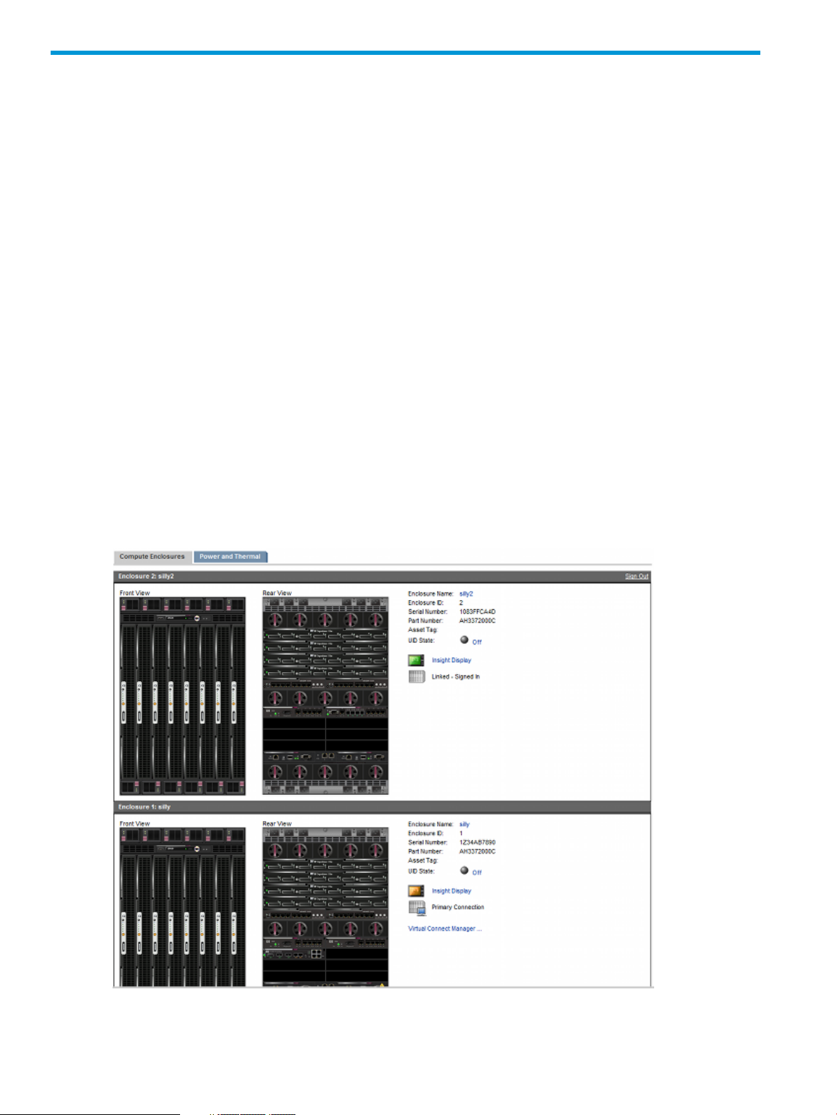
6 Complex Overview
Complex Overview screen
The Complex Overview screen displays a graphical representation of each compute enclosure in
the complex, called the graphical view. The graphical view consists of a front view and a rear
view of each enclosure.
The front view shows the presence and status of the following components:
• blades
• bulk power supplies
• the DVD module
The rear view shows the presence and status of the following components:
• PDUs
• X-Fabric Modules
• GPSMs
• OAs
• interconnect modules
• Fans
When you mouse over a device in the graphical view, a window appears with information on that
device. The graphical view provides status on each device in the enclosure and gives you the
option of selecting an individual device for viewing more detailed information.
60 Complex Overview
Page 61

Compute Enclosures tab
To update the complex topology information, click the Refresh Topology button.
Power and Thermal tab
The Power and Thermal tab displays information about the temperature inside each compute
enclosure and the thermal and power subsystem health status. A graphical view of the present
power and power limit helps you determine the power status.
NOTE: This information appears only for compute enclosures. Information is not included for
IOXs.
DescriptionItem
The DNS name of the enclosure and the name of the enclosure in the rack.Enclosure Name
The ID for the Enclosure in a multi-enclosure system.Enclosure ID
The unique serial number of the enclosure.Serial Number
The part number of the enclosure used when getting a new or replacement enclosure.Part Number
The tag used for inventory control.Asset Tag
Displays On or Off, depending on whether the UID is active.UID State
A link to the Insight Display page of the enclosure.Insight Display
Complex Overview screen 61
Page 62

Table 2 Compute enclosure cooling requirements
DescriptionItem
Current Btu/hr
Max Btu/hr
Table 3 Compute enclosure thermal and power status
Enclosure Ambient Temperature
Thermal Subsystem Status
Power Subsystem Status
Power Mode
62 Complex Overview
The sum of the amount of heat being generated by the complex enclosures measured in
Btu per hour.
The maximum amount of heat that can be generated by the complex enclosures under load
measured in Btu per hour.
DescriptionItem
This box displays the highest ambient temperature being reported by the installed
blade devices. If no blade devices are installed, then this box displays the
temperature of the Onboard Administrator module as an approximation of the
ambient temperature.
The overall thermal status of the enclosure. Possible values are Unknown, OK,
Degraded, or Critical Error.
The overall power status of the enclosure. Possible values are Unknown, OK,
Degraded, or Critical Error.
A user setting to configure the enclosure dc power capacity and the input power
redundancy mode of the enclosure. See “Power Management screen” (page 131)
for possible values.
Page 63

Table 3 Compute enclosure thermal and power status (continued)
DescriptionItem
The amount of watts being consumed by all devices in the enclosure.Present Power
Power Limit
The maximum amount of power available for consumption by the enclosure measured
in watts.
IMPORTANT: In a complex with one or more failed power supplies it is possible for attempts to
power on servers to fail if the resulting power allocation would result in the Power Redundancy
Status becoming Failed. The administrator must explicitly reduce the redundancy setting to enable
powering on servers prior to the failed power supplies being serviced. This applies to AC Redundant
and Power Supply Redundant power modes.
NOTE: If redundancy mode is set to AC Redundant, or Power Supply Redundant, and power
redundancy is lost, then you must either add additional power supplies or change the redundancy
mode setting in the Onboard Administrator to restore Power Subsystem status. See the Insight
Display for corrective steps.
NOTE: The Power Limit is dependent on the enclosure power redundancy setting and the number
and location of the power supplies in the enclosure. If a Static Power Limit has been specified, the
Power Limit displays that limit.
Complex Information screen
The Complex Information screen has three tabs:
• Status
• Information
• Complex Logs
• Complex CLI
Status tab
The Status tab provides the current operational status of the entire complex and the status of each
compute enclosure and IOX in the complex.
Complex Information screen 63
Page 64

DescriptionItem
The overall health of the complex. Possible values are Unknown, OK, Degraded, and Failed.Complex Status
CAMNET Status
Robust Store Status
Cooling Status
Thermal Status
Product ID
Enclosure ID
The Complex Status tab also displays general status information about each compute enclosure
and IOX in the complex beneath the overall status table.
64 Complex Overview
The overall health of the CAMNET fabric in the complex. Possible values are Unknown, OK,
Degraded, and Failed.
The health of the complex Robust Store. Possible values are Unknown, OK, Degraded, and
Failed.
The overall health of the cooling systems in the complex. Possible values are Unknown, OK,
Degraded, and Failed.
The overall thermal status of the complex. Possible values are Unknown, OK, Degraded, and
Failed.
The overall status of product IDs of all devices in the complex. Possible values are Unknown,
OK, Degraded, and Failed.
The overall status of enclosure IDs of all enclosures in the complex. Possible values are
Unknown, OK, Degraded, and Failed.
Page 65

Enclosure Status Overview
DescriptionColumn
The number of the compute enclosure in the complex.Enclosure Number
The assigned name of the compute enclosure.Enclosure Name
Status
IOX Status Overview
Information tab
The Information tab provides general information about the complex and an input box to change
the Complex Name.
The overall health of the compute enclosure. Possible values are Unknown, OK, Degraded,
and Failed.
DescriptionColumn
The number of the IOX in the complex.IOX Number
The assigned name of the IOX.IOX Name
The overall health of the IOX. Possible values are Unknown, OK, Degraded, and Failed.Status
Complex Information screen 65
Page 66

DescriptionItem
Common descriptive name of the Superdome 2 complexProduct Name
Name of the company that manufactured the complexManufacturer
The original product number of the complexOriginal Product Number
The current product number of the complexCurrent Product Number
The unique manufacturer serial number of the Superdome 2 complexSerial Number
The Universally Unique Identifier number assigned to the complexUniversal Unique Identifier
(UUID)
The number of the compute enclosure in the complex designated as the monarch enclosureMonarch Enclosure
Number
The total number of compute enclosures in the complexNumber of Enclosures
The total number of IOXs in the complexNumber of IOXs
The now configured firmware bundle version on the complexComplex Firmware Version
Settings box
The text input box below the Complex Information table enables you to change the Complex Name
for the complex. After choosing a Complex Name, to save changes, click the Apply button.
66 Complex Overview
Page 67

Complex Logs tab
The Complex Logs tab displays links to launch log viewers in new windows. The available log
viewers are the System Event Log, Forward Progress Log and the Live Log.
Complex CLI Tab
This tab opens a page that provides a link to launch a Command Line Interface shell on the Monarch
OA. Only one CLI session may be launched from the OA GUI. The CLI shell is a separate application
launched by the GUI and is displayed in its own separate window.
Complex Information: Firmware Management
This option can be expanded to show links for the following:
• Complex Firmware Summary
• Updating Firmware
Complex Firmware Summary screen
The Firmware Summary screen displays the current status of firmware in the complex.
Superdome 2 systems support two types of firmware, complex firmware that must be consistent
across all devices in the complex, and partition firmware that runs on the system processors of
server blades. Firmware on the system can be in one of three states:
• Configured – the firmware that should be running on a specific entity.
• Installed – the firmware that is currently installed and will become active on the next boot.
• Active – the version of firmware currently running on the system.
A table with the configured complex firmware version appears at the top of the screen. If any entity
within the complex does not have the correct complex firmware, a second table will be displayed
indicating which entities have mismatched firmware.
Table 4 Complex Firmware information
Configured Complex Firmware Version
Enclosure / Bay
DescriptionItem
The version of the firmware bundle currently configured on
the complex.
The compute enclosure and bay number of the device with
mismatched firmware
Complex Information: Firmware Management 67
Page 68

Table 4 Complex Firmware information (continued)
DescriptionItem
The model number of the deviceModel
The currently installed version of the firmware on the device.Installed Version
Each partition in the complex is displayed after the Complex Firmware, with the version of the
firmware currently configured and active on the partition. If any devices within a partition have
firmware versions do not match the currently installed version of the complex firmware on the
partition, they are displayed below the partition firmware information.
Table 5 Partition Firmware information
DescriptionItem
Configured Partition Firmware Version
Active Partition Firmware Version
Enclosure / Bay
The version of the firmware bundle currently configured on
the partition.
The version of the firmware bundle currently active on the
partition.
If the partition is not currently booted, the Active firmware
version will be displayed as “Not Available”
NOTE: The active version of the firmware will not match
the configured version if the partition requires a reboot
after a firmware update.
The compute enclosure and bay number of the device with
mismatched firmware.
Type of device with mismatched firmware.Model
The currently installed version of the firmware on the device.Installed Version
Online complex firmware update on Superdome 2
Introduction
Superdome 2 firmware release bundle 2.2.27 (web released in August 2011, factory enabled in
September 2011), brings an exciting capability to Superdome 2 customers. The ability to support
online complex firmware updates can dramatically reduce the amount of partition downtime
required for a customer to update their Superdome 2 systems to future firmware bundles. Under
certain conditions, partition downtime needed to apply a new firmware bundle can even be
eliminated entirely. However, there may also be other partition maintenance activities (OS patch
installations, for example) to complete during a maintenance window that will involve a partition
reboot in order to take effect. Also, it should be understood that firmware updates which include
68 Complex Overview
Page 69

new partition firmware packages (system firmware) will require a partition reboot to activate, but
the timing of such an operation can be done on an individual nPartition basis as determined by
the operator to best fit their individual needs.
When performing an online complex firmware update, Superdome 2 server management capabilities
are inactive, and this is something which operators should keep in mind. It should not be surprising
that server management entities throughout the Superdome 2 complex will bear responsibility to
update their own firmware Flash ROMs, reboot updated firmware images, and reestablish internal
communications with each other, but it is important to remind operators what kinds of management
services will become temporarily unavailable at the server level during an online complex firmware
update operation. This information is being provided to inform the user of such server management
limitations, but will not be a complete listing of all possible consequences which may be encountered
during an online complex firmware update.
Please note that Superdome 2 systems not already running a firmware bundle released prior to
(numbered lower than) 2.2.27 do not possess the capability to perform an online complex firmware
update, so it should be understood that updating to a future firmware bundle from firmware release
1.3.1, for example, must be performed with all partitions taken offline, and the xfabric powered
off.
Services unavailable
Superdome 2 server management features are unavailable during the process of an online complex
firmware update. System firmware will continue to operate and support the OS running on partitions
in the complex, however, certain activities may require system firmware to interact with server
management firmware, and these operations will not work during the actual process of executing
an online complex firmware update. These partition/complex firmware interactions may either be
delayed until after the complex firmware update operation has completed, or may be dropped or
only partially used. Legacy sx2000 Superdome systems also supported online update of server
management entities (MP, ED, PDHC, CLU), and performing such updates held similar consequences
for that platform.
The following table shows the major classes of server management services which the OS and
applications use during normal runtime and details their Availability or Unavailability during the
online complex firmware update process:
restart, TOC, console, logs)
Console service to OS
INIT and CMC logging operations
services). OS-debugger, HP-SIM XML query, HP-SUM SOAP
query, WEBES ws-manage events and query.
Management Processor access
When an online complex firmware update is initiated, all current users are disconnected from the
OA for the duration of the complex firmware update process. This includes all OA CLI and GUI
sessions, with one possible exception: If the operator initiates the firmware update from the CLI,
then this session will remain active to allow for tracking the progress of the update for all but the
last few minutes. The time it takes for a complex firmware update to complete is highly variable
based on system size and complexity (bigger systems take longer), and the number of firmware
Status during online complex firmware updateService
UnavailableManagement processor access (for example: poweron/off,
UnavailableIPMI services
Unavailable, and some character loss is possible if the
buffer fills up
AvailableSystem firmware services during boot, shutdown, MCA,
UnavailableNetwork management services (SD2 has additional
Complex Information: Firmware Management 69
Page 70

IPMI
packages in the bundle which must be updated, but is not expected to exceed 150 minutes under
any conditions. Typical firmware updates will take less time to complete.
During the process of an online complex firmware update, no IPMI requests can be serviced until
the update completes. This means that partition configuration changes, including iCAP changes,
will not be allowed. For reference purposes the following IPMI CLI commands are unavailable:
• parcreate
• pardefault
• pardbmgr
• parremove
• parmodify
• parstatus
• cplxmodify
• vparcreate
• vparremove
• vparmodify
• vparboot
• vparreset
• vparstatus
• icapmodify
• icapstatus
• plg9hlth
• seedGlobalMca
• perf-mode
• MPEventGen (Intel Itanium 9500 Series processors).
Event logs
Forward Progress Logs and System Event Logs normally captured by the server management system
will not be updated during the firmware update process.
IPMI Watchdog
During the online complex firmware update process, the IPMI watchdog timeout will be disabled.
It will be re-enabled when the system wakes up. The OS will discover the watchdog timer has
disappeared after the firmware update process has completed, and will recreate it by design.
Partition ID
The # getconf _CS_PARTITION_IDENT command (which returns HP-UX partition ID), is used
for licensing. It is a concatenation of UUID + nPartition # + vPar #. UUID is continuously available
from the SMBIOS table. The latter two (nPartition, vPar #s) are obtained using an IPMI call which
may fail during the firmware update process. HP-UX caches this information after the very first call
to getconf _CS_PARTITION_IDENT, so this command would only fail if it had never been run
before the firmware update process began.
70 Complex Overview
Page 71

Console
When the firmware update is in progress, the OS console cannot be serviced on the server
management side. Since all active sessions to the OA CLI and GUI interfaces are closed at the
beginning of the firmware update process, the OS console cannot be actively viewed during this
process. The OS console is normally a quiet interface with little character traffic; however there
are conditions (OS panics, for example) where the character buffer could potentially fill up during
the firmware update process. If the console character buffer is full during an active online complex
firmware update, new incoming characters will be dropped so the console does not hang on the
OS side. This potential for console character loss does not extend to kernel memory (dmesg) or
impact the OS syslog or crashdump area in any way, so this should not inhibit OS problem
diagnosis in the unlikely event something unexpected occurs at the OS level. The characters captured
in the buffer will be drained once the firmware update process completes, and console operation
will return to normal.
System Firmware Services During Boot, Shutdown, etc.
Certain partition events which occur while the OS is running may not be handled if they occur
while management firmware is unavailable:
• OS-requested restart (for example: TOC, shutdown –r)
• MCA
• HP-UX boot may hang until firmware update completes
In the cases above, the OS shutdown or restart may not complete. The system design does not
make any guarantees about successful handling of OS restart, MCA, or boot that occurs during
the online complex firmware update process, so HP recommends that the operator not attempt to
initiate operations like an OS shutdown, boot/reboot, cold installation, patch update, or a
Serviceguard cluster reconfiguration request during the online complex firmware update process.
Such actions should be performed serially to avoid potential conflict consequences.
All PAL and SAL calls do work during an online complex firmware update, as these commands
execute at the partition level and do not access server management resources. The following
services are not affected by the online complex firmware update process, and will remain
operational:
Get/SET EFI Variables
Calls to get/set EFI variables will work for the OS.
HPET Timer
The HPET timer will not be re-initialized, and this partition resource will remain available throughout
the firmware update process.
EFI_SetTime
System firmware will continue to maintain the correct time during an online firmware update.
Error Records
Error records can be generated as a result of INIT, CMC/CPE, and MCA.
• INITs are stored by system firmware in NVRAM, so these records will be available to the OS
after restart. They will be also be available to CLI errdump once the firmware update completes.
• Logging of CMC/CPE error records are unaffected by a PDHC or OA restart – errors not
logged before a restart are saved in hardware and will be logged after the restart
• MCA logs may be lost during this period, however system firmware will alert server
management that an MCA has occurred once the firmware update completes, and server
management will ensure the partition is reset and data integrity maintained.
Complex Information: Firmware Management 71
Page 72

Affected OS Commands
The machinfo command can print the firmware versions. This command may malfunction during
an active online complex firmware update operation when it attempts to print the BMC firmware
version, which is sourced via IPMI.
Network Services to OA
All network services provided by the OA are interrupted by the firmware update process. These
services include:
• XML inventory query from HP-SIM
• WS-MAN partition query from HP-SIM and plugins
• User interface (ssh, web, telnet) for all OA services
• SOAP request from GiCAP Group Manager, HP-SUM
• Kernel debugger connection through OA network port
• Console access through the OA
• Ping, SNMP queries
This is the same as legacy MP or C7000 OA (depending on the protocol) behavior during an
update.
Frequently asked questions:
Some sample questions are included below to aid the operator wishing to perform an online
complex firmware update.
72 Complex Overview
Page 73

1. Can Oracle use IPMI to reset a partition?
• Answer: Not during the online complex firmware update process.
2. Do virtual partition reboots proceed during online complex firmware update?
• Answer: HP can not guarantee completion of a reboot during this time, so the operator
should avoid initiating this action while in process. Reboot requests from an OS that occur
during an online complex firmware update will be queued and completed after the
firmware update process finishes.
3. GWLM asks for dynamic resource change (for example, Vparmodify), what happens when
it can not execute for an hour?
• Answer: GWLM tries a number of times and gives up, logs an error, will come back and
retry later. Changes won’t happen until it eventually tries later when the firmware update
process has completed.
4. How does field support debug if something happened during an online complex firmware
update?
• Answer: Kernel memory (dmesg), the OS syslog, and crashdump memory is unaffected,
so this will not inhibit debug for OS-related events. The loss of event logs during the
firmware update process is unavoidable (as it was on legacy sx2000 Superdome systems),
but the SEL will indicate start and finish times for the update process.
5. What happens if Serviceguard or other cluster software tries to TOC during an online complex
firmware update?
6. Will agents that require licensing or UUID find that information available during an online
Known issues:
The following observations are included to help the operator understand how the loss of server
management features might be visible from the OS perspective.
hpvminfo command qualifiers fail
The use of certain hpvminfo command qualifiers will return an ioctl error when executed during
Superdome 2 Online Firmware Update. This may also result in a delay before the results of the
command are displayed.
The affected commands include: hpvminfo, hpvminfo -V, and hpvminfo -v.
• Answer: If a node tries to TOC itself from an app running on the partition, the partition
OS will shut down to a point where it is ready to talk to server management. From an
application viewpoint, the system is down. It may or may not automatically restart when
the firmware update process completes. The service processor is unavailable during online
complex firmware update, so a node cannot successfully TOC another node.
complex firmware update?
• Answer:
◦ See the description under “Partition ID” (page 70) for details
◦ System firmware services are largely available during online firmware update
◦ Machinfo reports system firmware revision, BMC revision, FPSW revision
Newly created HPVM guests cannot be started
Any newly created HPVM guest cannot be started during Superdome 2 Online Firmware Update.
When you attempt to start the guest, the hpvmstart command will hang at "Initializing Forward
Progress Log." The hpvmstart command will complete successfully after the Online Firmware
Update has completed.
Complex Information: Firmware Management 73
Page 74

NOTE: This issue only pertains to newly created guests that have never been started. Guests that
have been started at least once prior to the Online Firmware Update will start without any problems.
Serviceguard Manager performance degradation and proxy errors
Serviceguard Manager may experience some performance degradation or report proxy errors
during Superdome 2 Online Firmware Update. These issues do not adversely affect the Serviceguard
cluster or applications being managed by Serviceguard. If you do receive a message about a
proxy error, you can resolve the issue by reloading the page. Performance returns to normal once
the Online Firmware Update has completed.
cimserver shutdown and startup fail
The cimserver command will timeout when attempting to shutdown or startup during Superdome
2 Online Firmware Update. Stopping or starting the cimserver process should be performed
before or after the Superdome 2 Online Firmware Update.
The affected commands include: cimserver -s and cimserver.
cimauth is unable to add authorizations
cimauth will fail to add authorizations during Superdome 2 Online Firmware Update. These
operations should be performed before or after the Superdome 2 Online Firmware Update.
Example of a cimauth command: cimauth -a -u wbem -n root -R -W
cprop command qualifiers fail
The use of certain cprop command qualifiers will report “Connection timed out” when executed
during Superdome 2 Online Firmware Update.
The affected commands include: cprop -summary -a and cprop -summary -Memory.
SMH is unable to query memory or enclosure information
The SMH is unable to query memory or enclosure information during Superdome 2 Online Firmware
Update. This information is properly reported before and after the Superdome 2 Online Firmware
Update.
setboot and related commands are unable to display or modify boot variables
The setboot command is unable to display or modify boot variables during Superdome 2 Online
Firmware Update. This also impacts any command that calls setboot.
The affected commands include: setboot, drd activate, drd status, vxbrk_rootmir,
and vxrootmir.
wbemassist namespace error
wbemassist reports a namespace error when checking the WBEM Server response.
par* and vpar* commands fail
Parcon services are not available during Superdome 2 Online Firmware Update. Due to this
unavailability, all par* and vpar* commands will fail.
The affected commands include, but are not limited to: parcreate, parmodify, parperm,
parstatus, vparcreate, vparmodify, vparstatus, and others.
Firmware Update screen
IMPORTANT: You cannot update firmware through the HP Superdome 2 Onboard Administrator
GUI if you have complex firmware earlier than the Online Firmware Update firmware release.
74 Complex Overview
Page 75

To update complex firmware if you have complex firmware earlier than the Online Firmware
Update firmware release, see the UPDATE FIRMWARE section in the HP Integrity Superdome 2
Onboard Administrator Command Line Interface User Guide.
If you select the firmware update link in the left navigation panel, the firmware update selections
screen will be displayed.
This screen displays the options available for firmware update:
• Analysis Only - Use this option to display the actions that will be executed by the update. This
option will run the analyze update and exit without executing the update. No Firmware will
be modified.
• Force Downgrade - Use this option if you are downgrading the firmware to a previous version.
The firmware update process will fail if you are downgrading and this option is not selected.
• Reinstall - Use this option to reinstall a firmware bundle of the same revision as the one already
on the system. By default, entities with the current version of firmware will not be updated.
This option will overwrite every image on the system so it may take longer than other options.
The next table on this screen allows for the selection of the Update Type:
• Update All Firmware - This option will update ALL Complex and Partition Firmware on the
system.
• Update Complex Firmware - This option will update only the Complex Firmware on the system.
• Update nPartition Firmware - This option will update the nPartition Firmware for the selected
entities.
NOTE: If Update nPartition Firmware is selected, a new table will be appear that allows the
selection of unassigned blade resources and existing partitions.
You can select all or one or more partitions or blades from each list. After the update type and
targets are selected, you will need to determine if the firmware image being installed is from a
URL or is located on a USB drive plugged into the DVD module in enclosure 1. USB update options
are only shown when a USB drive is plugged in and has a valid firmware image on it.
IMPORTANT: To update firmware on a Superdome 2 System, you must be an “Administrator”
level user assigned access to the partitions which you are attempting to update. Partition firmware
update will not be allowed without assigned access to the partition.
Firmware image download
After starting an update, a progress bar showing the progress of the firmware image download
will be displayed.
Firmware analysis
When the firmware bundle download completes, the GUI will display a wait bar while the system
runs the firmware analysis.
After the system completes the firmware analysis, the GUI will display the analysis results on an
analysis page. This page will contain sections that may display notice, warning, and error messages.
It will also display the list of partitions and components that will be updated if the analysis was
successful.
Complex Information: Firmware Management 75
Page 76

If the analysis fails, you will not be supplied with further options.
If the Analysis Only option was not selected, then the firmware update will automatically continue
after 30 seconds. During this time the you will have the option to cancel the update using the
Cancel Update button at the bottom of the analysis page.
Update Status
When the firmware update starts, the page will change to display the update status page. This
page will show the current status of the update.
76 Complex Overview
Page 77

The following information will be displayed:
• The status of each component being updated.
• The total number of components that will be updated.
• The number of component updates either completed successfully or failed.
• The estimated time remaining in the update.
IMPORTANT: When two partitions share a single IOX, you will have to reboot both partitions in
order to use the new firmware.
The interface does not allow the ability to do two or more concurrent updates. If another user
attempts to initiate an update, an alert appears.
Enclosure DVD Module screen
The DVD module in a compute enclosure can be used by a partition to perform software installations
and updates in the same manner as a standard DVD drive is used in a computer system locally or
remotely.
The DVD module is not connected to any partitions in the complex after initial installation. To use
the DVD drive, an administrator must first connect the DVD module to any or all partitions through
Enclosure DVD Module screen 77
Page 78

the Onboard Administrator CLI or by navigating to the Complex nPartitions menu and selecting
the Virtual Devices tab.
For more information, see the HP Integrity Superdome 2 Partitioning Administrator Guide.
Information on the Enclosure DVD screen is current as of the last download. To view updated
information, click the Refresh button.
Status and Information tab information
DescriptionItem
Current status of the DVD module. Possible values are OK, Degraded, or Not Present.Status
The common descriptive name of the DVD module.Product Name
The name of the company that manufactured the DVD module.Manufacturer
The unique serial number of the DVD module.Serial Number
The part number to use when ordering an additional DVD module of this type.Part Number
The part number to use when ordering a replacement DVD module of this type.Spare Part Number
Manufacturing information about the DVD module.Engineering Date Code
Diagnostic Information
DescriptionItem
Device Identification Data
Power Allocation Request
Contains information on model name, part number, serial number, and other information
used to identify the device. This data is also called FRU data. Device identification data
error displays if the data is not present or not readable by the Onboard Administrator.
There is insufficient power to adequately power the DVD module. Possible values are OK
or Insufficient enclosure power.
78 Complex Overview
Page 79

7 Configuring HP Integrity Superdome 2 compute enclosures
and enclosure devices
Viewing the status screens
Each compute enclosure in the complex can be selected from the left navigation tree. Clicking the
enclosure name opens the main status screen of the enclosure.
On this page, three tabs are available at the top of the main page:
• Status
• Information
• Virtual Buttons
The Status tab displays one of the following values as Overall Enclosure Status:
• Critical/Failed
• Major
• Minor/Degraded
• Warning
• Normal/OK
• Disabled
• Unknown
• Informational
The Active HP Superdome 2 Onboard Administrator Status and Standby HP Superdome 2 Onboard
Administrator Status are similar to the Overall Enclosure Status and display a status for the Onboard
Administrator. If a Standby Onboard Administrator is not present in the system, its status value is
Absent.
Enclosure Power Mode displays the current power mode of the enclosure. The following values
are possible:
• AC Redundant
• Power Supply Redundant
• Not Redundant
The Enclosure Device Status Overview is divided into four sections:
• Device Bay Overview
• Power Supply Overview
• Interconnect Bay Overview
• Fan Overview
For each of these sections, the following values are possible:
• Critical/Failed
• Major
• Minor/Degraded
• Warning
• Normal/OK
• Disabled
Viewing the status screens 79
Page 80

• Unknown
• Informational
Enclosure settings
Enclosure Settings screen
This section provides detailed procedures to configure the management functionality provided by
the HP Superdome 2 Onboard Administrator.
Select the tree view menu item Enclosure Information to view the enclosure Status screen.
Table 6 Status overview information
DescriptionItem
The overall status of the enclosure. Possible values are Unknown, OK, Degraded, and Failed.Enclosure Status
Active OA Status
Standby OA Status
Power Mode
80 Configuring HP Integrity Superdome 2 compute enclosures and enclosure devices
The overall status of the active Onboard Administrator. Possible values are Unknown, OK,
Degraded, and Failed.
The overall status of the standby Onboard Administrator. Possible values are Absent, Unknown,
OK, Degraded, and Failed.
The power redundancy mode. Possible values are AC Redundant, Power Supply Redundant,
Not Redundant, or Unknown. For information on these modes, see the HP Integrity Superdome
2 User Guide.
Page 81

Diagnostic information
Diagnostic information is gathered by polling a device microcontroller (resulting in a degraded
status if a failure has occurred), or is sent by the device microcontroller, without being polled to
report a failure.
DescriptionItem
Device Identification Data
Device Operational
Contains information on model name, part number, serial number, and other information
used to identify the device. This data is also called FRU data. Device identification data
error displays if the data is not present or not readable by the Onboard Administrator.
Possible values are OK or Error. View the syslog for errors. Possible reasons for the error
are mismatched firmware or a software or hardware failure.
Indicates if the device has been indicted by the Superdome 2 Analysis Engine.Device Indictment
Table 7 Subsystems and Devices information
DescriptionTable
Device Bay Overview
All Device Bays
Interconnect Bay Overview
All Interconnect Bays
X–Flex Bay Overview
All XFM Bays
GPSM Bay Overview
All GPSM Bays
Power Subsystem
System Status
The overall status of all device bays. Possible values are Unknown, OK, Degraded, and
Failed.
The overall status of the interconnect bays. Possible values are Unknown, OK, Degraded,
and Failed.
The overall status of the XFM bays. Possible values are Unknown, OK, Degraded, and
Failed.
The overall status of the GPSM bays. Possible values are Unknown, OK, Degraded, and
Failed.
The overall status of the Power Subsystem of the enclosure. Possible values are Unknown,
OK, Degraded, and Failed.
Power Supply Summary
All Power Supplies
Thermal Subsystem
System Status
All Fans
The overall status of the power supplies. Possible values are Unknown, OK, Degraded,
and Failed.
The overall thermal status of the enclosure. Possible values are Unknown, OK, Degraded,
and Failed.
The overall status of the fans. Possible values are Unknown, OK, Degraded, and Failed.Fan Overview
NOTE: If any subsystem contains a component with a status other than OK, all components of
that subsystem with a status other than OK are displayed inline.
Enclosure settings 81
Page 82

Enclosure Information tab
DescriptionItem
The general description of the enclosure componentPart
The model name of the enclosure componentModel
Manufacturer
Part Number
Spare Part Number
82 Configuring HP Integrity Superdome 2 compute enclosures and enclosure devices
The name of the company that manufactured the enclosure
component
The unique serial number of the enclosure componentSerial Number
The part number to be used when ordering an additional
enclosure component
The part number to be used when ordering a replacement
enclosure component
Page 83

Changing settings
You can change enclosure settings from this screen. To save the settings after making the changes,
click the Apply button.
DescriptionPossible valueItem
Enclosure Name
Rack Name
Asset Tag
Virtual Buttons tab
To change the state of the enclosure UID, click the Toggle On/Off button. The enclosure UID is
located to the left of the Enclosure link-down port.
AlertMail screen
AlertMail enables users to receive system events by email instead of using SNMP traps. AlertMail
is completely independent from SNMP, and both can be enabled at the same time. AlertMail uses
standard SMTP commands to communicate with an SMTP-capable mail server. The "Reply To"
address for each email sent by AlertMail is <Enclosure Name>@<Alert Sender Domain>. To enable
the AlertMail feature, select the Enable AlertMail check box.
To test the AlertMail function:
1. Be sure that the email address, alert sender domain, and SMTP server settings are correct.
2. Select the Send Test AlertMail button.
3. To confirm that the test completed successfully, verify the recipient email account.
alphanumeric characters, the dash (-),
and the underscore (_)
1 to 32 characters including all
alphanumeric characters, the dash (-),
and the underscore (_)
0 to 32 characters including all
alphanumeric characters, the dash (-),
and the underscore (_)
The name of the selected enclosure1 to 32 characters including all
The name of the rack in which the
enclosure is installed
The asset tag is used for inventory
control.
The default asset tag is blank
Enclosure settings 83
Page 84

NOTE: The Alert Sender Domain might not be required. The information in this box depends on
the mail server setup.
DescriptionPossible valueBox
This box is a valid email address for
the administrator or other designated
individual receiving the AlertMail
The domain in which the Onboard
Administrator resides
An IP address for the SMTP server###.###.###.### where ### ranges
Alert Sender Domain
SMTP Server
<account>@<domain>E-mail address
A character string including all
alphanumeric characters and the dash
(-)
from 0 to 255
To enable the AlertMail feature:
1. Select the Enable AlertMail check box to enable the AlertMail feature.
2. Enter values for the email address, alert sender domain, and SMTP server.
3. Click the Apply button to save the settings.
AlertMail, if enabled, sends alerts by email for the following events:
• Enclosure status change
• Enclosure information change
• Fan status change
• Fan inserted
• Fan removed
• Power supply status
• Power supply inserted
• Power supply removed
• Power supply overload
• Blade inserted
• Blade removed
• Blade status
• Blade thermal condition
• Blade fault
• Blade information change
• Tray status change
• Tray reset
• Switch connect
• Switch disconnect
All e-mails have the following header:
From: Enclosure ENCLOSURE-NAME <enclosure-name@serverdomain>
Date: Date in standard format
Subject: HP AlertMail-SEQ: <SEVERITY> SUBJECT
To: RECEIVER MAILBOX
84 Configuring HP Integrity Superdome 2 compute enclosures and enclosure devices
Page 85

Where <SEVERITY> is one of the following (from highest to lowest):
• # FATAL
• # CRITICAL
• # WARNING MAJOR
• # WARNING MINOR
• # WARNING
• # NORMAL
Each subject line contains a unique sequence number to easily identify the order of events in case
the mail server distributes them in the wrong order. Sequence numbers range from 0 to 999 and
restart at 0.
The mail body is used to give more detailed information regarding the event issued. The mail body
also contains information on what the user must do to correct any issue and what the current
enclosure status is.
NOTE: The enclosure status is displayed as the status at the time when the event is processed
which can cause the status to show up as OK in an email saying a Fan has Failed if the user
replaced the fan at the time the event is sent out by AlertMail.
Sample email
Subject: HP AlertMail-010: (CRITICAL) Power Supply #1: Failed
Date: Wed, 23 Apr 2006 15:02:22 +0200
From: Enclosure EM-00508BEBA571 <EM-00508BEBA571@hp.com>
To: user@domain
X-OS: HP Superdome 2 Enclosure Manager
X-Priority: 1
Content-Type: text/plain; charset=us-ascii
EVENT (26 May 07:09): Power Supply #1 Status has changed to: Failed.
Enclosure, EM-00508BEBA571, has detected that a power supply in bay 1 has changed from status OK to Failed.
The power supply should be replaced with the appropriate spare part. You can ensure that the center wall assembly
is
operating correctly by swapping the two power supplies. Make sure that there are no bent pins on the power
supply connectors before
reinserting and that each power supply is fully seated.
An amber LED on the power supply indicates either an over-voltage, over-temperature, or loss of AC power has
occurred.
A blinking LED on the power supply indicates a current limit condition.
Enclosure Status: Degraded
Enclosure Management URL: https://16.181.75.213/
- PLEASE DO NOT REPLY TO THIS EMAIL -
Device Power Sequence Device Bays tabs
The enclosure power delay feature controls the order in which components are powered on if the
entire enclosure has been power cycled. This feature is only enabled during the active HP Superdome
2 Onboard Administrator boot process if the Onboard Administrator detects that the entire enclosure
has been power cycled and power delay has been enabled on at least one component in the
enclosure.
The active HP Superdome 2 Onboard Administrator displays a message in the system log when
power delay has been initiated, and also displays a message in the system log when power delay
has completed after the longest power delay has passed. The HP Superdome 2 Onboard
Administrator factory default setting is to disable power delay for all components.
Enclosure settings 85
Page 86

Typical use cases involving bay to bay dependencies that can be resolved by enabling the enclosure
power delay feature include:
• Boot from network— Network interconnects must complete power on self test prior to servers
that are configured to boot from the network (for example, PXE or iSCSI).
• Boot from SAN— SAN interconnects must complete power on self test prior to servers that are
configured to boot from SAN
• Critical service dependencies controlled by a server such as DHCP or licensing
• Storage servers must be operational prior to servers requiring those resources
The delay time setting must be determined empirically since some dependencies are outside the
enclosure (boot from SAN might require additional delay to enable the datacenter SAN storage
system to power on). Each interconnect module has different power on timing before it is operational.
The timer used for power delay is started at the time the Onboard Administrator enters the first
system log message during Onboard Administrator initialization indicated by the system log
message Kernel: Network link up. When the HP Superdome 2 Onboard Administrator
indicates PowerDelay has been initiated for the selected devices in the system
log, the configured delay times for each bay are used to determine when that component is turned
on. After the selected delay time has elapsed, that component is turned on.
Valid settings for each bay are: Disabled, Enabled and No Poweron.
• Disabled — Disables powerdelay for this bay. HP Superdome 2 Onboard Administrator grants
power to this bay based on its power settings: for a device configured to auto power-on, the
device is granted power following an enclosure power cycle after all the Onboard Administrator
configuration checks are complete.
• Enabled— Enables powerdelay for this bay. HP Superdome 2 Onboard Administrator turns
on this bay based on the number of seconds elapsed following the detection of an enclosure
power cycle event.
• No Poweron— Prevents component power on for the bays with this configuration until after
the HP Superdome 2 Onboard Administrator logs PowerDelay has completed for
the selected devices. At this time, if the device is configured to auto power-on, the
device grants power following an enclosure power cycle after all the Onboard Administrator
configuration checks are complete.
If the device is configured to disable auto poweron, the device remains off following an enclosure
power cycle independent of the setting of power delay for that bay.
Device Bays Standard tab
The Device Bays Standard tab indicates the current settings for all the primary bays based on the
type of enclosure. To change a setting on a particular device bay, use the menu under the Enabled
column and select Enabled, Disabled or No Poweron. If Enabled is selected, a power delay in
seconds must be entered in the Delay column for this bay. The minimum value is 1 second; the
maximum value is 3600 seconds.
Interconnect Bays tab
Interconnect bays by default are for auto power-on. Enabling and setting a power delay for an
interconnect bay delays the power on of that bay following an enclosure power cycle event.
DescriptionColumn
Bay number of the device.Bay
Device
86 Configuring HP Integrity Superdome 2 compute enclosures and enclosure devices
The type of device in the bay, or Absent if no device is
installed in the bay
Page 87

DescriptionColumn
Enabled
Delay
Device Power Sequence Interconnect Bays tab
Device
Enabled
Delay
Click the Apply button to save the settings.
Date and Time screen
Enables power sequencing, disables power sequencing,
or does not allow powering on of the device if No Poweron
is selected.
The amount of delay, in seconds, before the device powers
on.
DescriptionColumn
Bay number of the deviceBay
The type of device in the bay or Absent if no device is
installed in the bay
Enables power sequencing, disables power sequencing,
or does not allow powering on of the device if No Poweron
is selected.
The amount of delay, in seconds, before the device powers
on. Possible delay values are 1 to 3600.
NOTE: The RTC in an nPartition is synced to OA time when the nPartition is rebooted. If you
change the time on the OA, it may affect the RTC on the nPartition.
Static date and time settings
The date and time are static and not updated in real-time. The date and time can only be set when
NTP is disabled.
DescriptionPossible valueBox
The date assigned to the enclosureyyyy-mm-ddDate
• mm is an integer from 1 to 12
• dd is an integer from 1 to 31
The time assigned to the enclosurehh:mm:ss (24-hour time, ss is optional)Time
• hh is an integer from 0 to 23
• mm is an integer from 0 to 59
• ss is an integer from 0 to 59
The time zone assigned to the enclosureTime zone settingsTime Zone
• “Africa time zone settings” (page 190)
• “Americas time zone settings” (page 190)
• “Asia time zone settings” (page 192)
• “Universal time zone settings” (page 192)
• “Oceanic time zone settings” (page 193)
• “Europe time zone settings” (page 193)
• “Polar time zone settings” (page 194)
Enclosure settings 87
Page 88

NTP settings
To enable this feature, select Set time using an NTP server.
DescriptionPossible valueBox
Primary NTP Server
Secondary NTP Server
###.###.###.### where ### ranges from 0 to
255
###.###.###.### where ### ranges from 0 to
255
• “Africa time zone settings” (page 190)
• “Americas time zone settings” (page 190)
• “Asia time zone settings” (page 192)
• “Universal time zone settings” (page 192)
• “Oceanic time zone settings” (page 193)
• “Europe time zone settings” (page 193)
• “Polar time zone settings” (page 194)
To save the settings, click the Apply button.
Enclosure TCP/IP Settings screen
This screen displays the current enclosure TCP/IP settings for the Active Onboard Administrator
and enables you to change the following settings:
• Enclosure IP Mode: The Enclosure IP Mode ensures all management applications point to the
active Onboard Administrator of the enclosure, using a single static IP address. This mode is
for enclosures with an active and standby Onboard Administrator. When the standby Onboard
Administrator takes over the role of the active Onboard Administrator, the Onboard
Administrator assumes the IP address of the previous active Onboard Administrator. This
ensures the Enclosure IP Mode IP address is consistently pointing to the active Onboard
Administrator.
The Enclosure IP Mode requires the active Onboard Administrator to have a static IP address.
Before enabling Enclosure IP Mode, you must configure a static IP address for the Active
Onboard Administrator. The standby Onboard Administrator can be configured for DHCP or
static IP settings. This mode is optional and is disabled by default.
The transition times from standby to active and active to standby varies, depending on the
configuration, enclosure population, and various other factors. The transition of standby to
active is normally 30 seconds. The transition of the previous active to standby is normally 90
seconds.
IP address of primary NTP server that
provides date and time information
IP address of secondary NTP server that
provides date and time information
The time zone assigned to the enclosureTime zone settingsTime Zone
IMPORTANT: Replace the standby Onboard Administrator only while the enclosure is
powered on to be sure that the Enclosure IP Mode settings are not changed.
• DHCP— Gets the IP address for the Onboard Administrator from a DHCP server
88 Configuring HP Integrity Superdome 2 compute enclosures and enclosure devices
Page 89

• Enable Dynamic DNS— Enables you to use a DNS server to translate host names into IP
addresses
• Static IP Settings— Enables you to manually set up static IP settings for the Onboard
Administrator
DescriptionPossible valueBox
DNS Host Name
MAC Address
IP Address
Subnet Mask
Gateway
DNS Server 1
DNS Server 2
alphanumeric characters and the dash (-)
changed
###.###.###.### where ### ranges from
0 to 255
###.###.###.### where ### ranges from
0 to 255
###.###.###.### where ### ranges from
0 to 255
0 to 255
0 to 255
The DNS Name of the Onboard AdministratorCan be 1 to 32 characters including all
The Onboard Administrator MAC addressThis is an informational box and cannot be
Static IP address for the Onboard
Administrator (required if static IP settings is
selected)
Subnet mask for the Onboard Administrator
(required if static IP settings is selected)
Gateway address for the Onboard
Administrator (required if static IP settings is
selected)
The IP address for the primary DNS server###.###.###.### where ### ranges from
The IP address for the secondary DNS server###.###.###.### where ### ranges from
NIC settings
• Auto-Negotiate— Automatically configures the best link. This is the default setting. This option
supports a NIC speed of 10 Mb/s, 100 Mb/s, or 1000 Mbps. The 1000 Mb/s setting is
only available when you select Auto-Negotiate.
• Forced Full Duplex— Enables you to manually specify which settings the external NIC uses
when trying to establish a link. Onboard Administrator does not verify that the forced Ethernet
settings are valid on the network. The loss of communications can occur if the wrong or
incompatible settings are used. Forced settings take effect 3 seconds after enabling or disabling
the settings. The forced option supports only NIC speeds of 10 Mbps or 100 Mb/s.
• NIC Speed— Selects an NIC speed of 10 Mb/s or 100 Mb/s.
To save the new settings, click the Apply button.
Network Access screen
In this section, an administrator can configure settings relating to network access to the Onboard
Administrator. These settings are specific to the enclosure and do not affect the network
configurations for server blades.
Enclosure settings 89
Page 90

The Protocol Restrictions subcategory is used to restrict access to the Onboard Administrator. Up
to four protocol settings can be selected to allow or restrict access to the Onboard Administrator.
• Enable Web Access (HTTP/HTTPS)— This check box is selected by default. Clearing this check
box disables HTTP/HTTPS access to the Onboard Administrator. Port 80 is used for HTTP and
port 443 is used for HTTPS.
CAUTION: Disabling Web Access (HTTP/HTTPS) disconnects all users attached to the
Onboard Administrator through HTTP/HTTPS, including the administrator.
• Enable Secure Shell— This check box is selected by default. Clearing this check box disables
Secure Shell connections to the Onboard Administrator. Secure Shell is disabled when
Two-Factor Authentication is enabled. Disabling Two-Factor Authentication does not
automatically re-enable Secure Shell. To re-enable Secure Shell, you must select the check box
and then click Apply. Port 22 is used.
• Enable Telnet— This check box is selected by default. Clearing this check box disables Telnet
connections to the Onboard Administrator. Telnet is disabled when Two-Factor Authentication
is enabled. Disabling Two-Factor Authentication does not automatically re-enable Telnet. To
re-enable Telnet, you must select the check box and click Apply. Port 23 is used.
• Enable XML Reply— This check box is selected by default. Selecting this check box enables
XML data to be shared between the Onboard Administrator and other HP management tools
such as HP Systems Insight Manager. To display the information that is shared by the Onboard
Administrator if this protocol is enabled, click View.
• Enable WS-Management— Selecting this check box enables the WS-Management connections
to the Onboard Administrator. WS-Management is enabled by default.
To save the settings, click the Apply button.
Trusted Hosts tab
The Trusted Hosts subcategory is used to restrict access to the Onboard Administrator to all hosts
except those listed. When enabled, this protocol allows access only to the Onboard Administrator
to listed hosts.
This subcategory contains one dialog box, one entry box, and one display box, which, if enabled,
is used to list trusted IP addresses.
The Enable IP address access restriction check box is not selected by default. Selecting this check
box allows only those IP addresses listed as Trusted Addresses to connect to the Onboard
Administrator.
CAUTION: Enabling IP address access restriction without first entering the user IP address in the
Trusted Addresses list disconnects the user from the Onboard Administrator.
The Trusted Addresses box is used to enter the IP addresses of all hosts that are to be trusted and
allowed to connect remotely to the Onboard Administrator through the protocols set up in the
Protocol Restrictions subcategory. This box allows for IP addresses only.
Under the Trusted Addresses box is the list box of all trusted IP addresses, if trusted IP addresses
are configured.
• To add a trusted host, enter the IP address in the Trusted Addresses box, and then click Add.
You can add a maximum of five Trusted Addresses.
• To remove a trusted host, select the IP address in the Trusted Addresses list, and then click
Remove.
• To save the settings, click the Apply button.
90 Configuring HP Integrity Superdome 2 compute enclosures and enclosure devices
Page 91

Anonymous Data tab
Enable Extended Data on GUI Login Page— This check box is selected by default. Clearing this
check box disables the "+" functionality in the topology view on the log on page for this enclosure.
Disabling the extended data on the GUI log on page prevents unauthenticated users from viewing
additional information. To prevent additional information from appearing for each linked enclosure,
you must clear this check box for each enclosure.
To save the settings, click the Apply button.
Link Loss Failover screen
This screen enables you to configure automatic Onboard Administrator redundancy failover based
on network link status. For Link Loss Failover to function correctly, the redundancy status of the
Onboard Administrators must be OK. An OK status means that both Onboard Administrators have
the same firmware version, and that they are communicating properly.
Enable Link Loss Failover— This check box enables or disables automatic Link Loss Failover.
Failover Interval— The failover interval is the amount of time the active Onboard Administrator
must be without a link on the external Ethernet interface before the system considers an automatic
failover. The interval must be between 30 and 86400 seconds.
To save the settings, click the Apply button.
Enclosure Bay IP Addressing screen
There is an important difference between the network the Superdome 2 complex is connected to
and the management network that the Onboard Administrator uses. Enclosure Bay IP Addressing
is used to assign IP addresses to the iLO 3 processors that are bridged through the Onboard
Administrator and must not be confused with port mapping for the server blade NICs or for network
routers or switches. EBPIA does not assign IP addresses for any other device on the network, and
cannot be used as a DHCP server on the network.
The server blade iLO 3 ports and interconnect module management ports can get IP addresses on
the management network in the following ways:
• DHCP address — The server blade iLO 3 defaults to DHCP addressing, through the network
connector of the active Onboard Administrator. Interconnect modules that have an internal
management network connection to the Onboard Administrator may also default to the DHCP
address.
• EBIPA — When a server blade or interconnect module is inserted into a bay that has EBIPA
enabled, that management port will receive the specific static IP address from the Onboard
Administrator if that device is configured for DHCP.
Link-local addresses:
To save IP addresses, link-local addressing can be used. Link-local IP addresses can be assigned
to blades, iLOs, and interconnect bays within an enclosure. Link-local addresses are intended only
for use within a segment of a network and can be used for network configurations that do not
require allocated IP addresses on the network.
As a best practice HP recommends the following rules for assigning iLO IP addresses:
• The Monarch Npar IP address should be assigned using EBPIA/DHCP.
• The Auxiliary blades should be assigned using link-local addressing to save IP addresses.
For more information on setting up link-local addresses, see the HP Integrity Superdome 2 Command
Line Interface User Guide.
Enclosure settings 91
Page 92

The administrator sets an independent range for server blade bays and interconnect module bays
using the Onboard Administrator EBIPA setup wizard. The first address in a range is assigned to
the first bay and then consecutive bays through the range.
To set up your enclosure without an active network connection using EBIPA:
1. Configure a static IP for each Onboard Administrator using the Insight Display, and note the
active OA Service IP address on the Insight Display Enclosure Info screen. Attach the client
PC to the enclosure Service Port (Enclosure Link Up connector) between the OA bays with a
standard Ethernet patch cable. The client PC NIC must be configured for DHCP because it
gets an IP address in the range of 169.254.x.y approximately 1 minute later.
2. Launch a web browser (or alternatively a Telnet or Secure Shell session), and select the
Onboard Administrator Service IP address as displayed in the enclosure Insight Display on
the Enclosure Info screen.
3. Log into the Onboard Administrator as Administrator, and use the administrative password
attached to the active Onboard Administrator.
4. While the First Time Setup Wizard is running (alternately, after first time setup you can change
the EBIPA settings in the Enclosure Settings list), enable Device Bay EBIPA with a starting static
IP address and enable Interconnect Bay EBIPA with a different starting IP address. The Onboard
Administrator then creates 16 sequential IP addresses for the device bays and 8 sequential
IP addresses for the interconnect bays. Servers in the device bays will automatically get the
Device Bay EBIPA addresses within a minute, but the interconnect switch modules must to be
manually restarted by clicking the Virtual Power button on each Onboard Administrator
Interconnect Module Information screen.
5. Use the Onboard Administrator Device list to be sure that the server blade iLO addresses have
been set according to the EBIPA starting IP address and range.
When a server blade or interconnect module is inserted into a device bay that has EBIPA enabled,
the management port gets the specific static IP address from the Onboard Administrator if the
device is configured for DHCP. If the device is configured for static IP, it must be manually
reconfigured to DHCP to change to the EBIPA IP address.
The administrator sets an independent range for device bays and interconnect module bays using
the Onboard Administrator EBIPA setup wizard. The first address in a range is assigned to the first
bay and then consecutive bays through the range.
For example, if you set the server bay EBIPA range starting from 16.100.226.21 to 16.100.226.36,
the iLO 3 in Server bay #1 will be assigned 16.100.226.21 and the iLO 3 in Server bay #12 is
assigned 16.100.226.32, and the interconnect bay EBIPA range to 16.200.139.51 to
16.200.139.58. If you set the interconnect module port, the interconnect bay #1 is set to
16.200.139.51 and the interconnect module management port in Interconnect bay #7 is set to
16.200.139.57.
92 Configuring HP Integrity Superdome 2 compute enclosures and enclosure devices
Page 93

Knowing your network configuration before setting up EBIPA ensures an easy setup and enables
you to install your HP Superdome 2 Onboard Administrator on to your network quickly. Record
the information requested in the boxes on the EBIPA screen, and verify before entering the data.
Use only the possible values listed in the following table.
DescriptionPossible valueBox
Subnet Mask
Gateway
Domain
DNS Server 1
DNS Server 2
DNS Server 3
Subnet mask for the device bays###.###.###.### where ### ranges from 0
to 255
Gateway address for the device bays###.###.###.### where ### ranges from 0
to 255
Domain name for the device baysA character string with a maximum of 64
characters, including all alphanumeric
characters and the dash (-)
The IP address for the primary DNS server###.###.###.### where ### ranges from 0
to 255
The IP address for the secondary DNS server###.###.###.### where ### ranges from 0
to 255
The IP address for the tertiary DNS server###.###.###.### where ### ranges from 0
to 255
Enclosure settings 93
Page 94

Device list
DescriptionColumn
The bay in the enclosure of the device.Bay
Enabled
Autofill
SNMP Settings screen
The Onboard Administrator supports SNMP Version 1 and several groups from the standard MIB-II
MIB. Additional information about the enclosure infrastructure is available in the HP Rack Information
MIB. CPQRACK-MIB, which is part of the Insight Management MIBs, is available on the Management
CD in the Superdome 2 Essentials Foundation Pack.
The SNMP Settings screen enables you to enter system information and community strings and
designate the management stations that can receive SNMP traps from the Onboard Administrator.
If you select Enable SNMP, then the Onboard Administrator responds to SNMP requests over UDP
port 162. Port 162 is the standard UDP port used to send and receive SNMP messages.
System Information settings
Enables EBIPA settings for the device bay. EBIPA settings for all device bays can be enabled
by selecting the check box next to Enabled in the heading row or individual device bays can
be selected by clicking the check box for that particular device bay.
The static IP address you want to assign to the device bay.EBIPA Address
Assigns consecutive IP addresses for the selected device bays below in the device list. Click
the autofill down arrow to assign the IP addresses.
The current IP address of the device bay.Current Address
The type of device installed in the device bay.Device Type
In the System Information subcategory, information about the Onboard Administrator SNMP system
can be enabled and configured.
94 Configuring HP Integrity Superdome 2 compute enclosures and enclosure devices
Page 95

The Enable SNMP check box is not selected by default. When enabled, the Onboard Administrator
can be polled for status and basic information. The SNMP client can only clear SNMP alerts and
status when the Write Community string is enabled. Clearing the Enable SNMP check box disables
SNMP access to the Onboard Administrator.
DescriptionPossible valueBox
System Location
System Contact
Read Community
Write Community
0 to 20 characters including all alphanumeric
characters, the dash (-), the underscore (_), and
the space
0 to 20 characters including all alphanumeric
characters, the dash (-), the underscore (_), and
the space
0 to 20 characters including all alphanumeric
characters, the dash (-), the underscore (_), and
the space
0 to 20 characters including all alphanumeric
characters, the dash (-), the underscore (_), and
the space
The SNMP location of the enclosure, typically
used to identify the physical or topographical
location of the Onboard Administrator.
The name of the system contact, used to identify
an individual or group of individuals who are
to be contacted in the event of any status change
in the HP Superdome 2 Onboard Administrator.
The Read Community string enables the client
to read information, but not to manipulate the
alerts or status of the HP Superdome 2 Onboard
Administrator through SNMP. The default
community name is "public" and enables a user
to receive notification traps and alerts, but not
to change or manipulate the status.
The Write Community string enables the client
to manipulate alerts of HP Superdome 2
Onboard Administrator status through SNMP.
You can remotely clear alerts and mark them as
"viewed" or otherwise through their SNMP
management client through the SNMP agents.
The default value for the Write Community string
is blank.
Enclosure settings 95
Page 96

Edit any of the fields in this subcategory, and to save the changes, click the Apply button.
SNMP Alert Destinations settings
In the SNMP Alert Destinations subcategory, the IP addresses and community strings for the SNMP
management clients are configured so that any alert or trap from the Onboard Administrator is
sent to the appropriate system with the community string.
DescriptionPossible valueBox
IP Address
Community String
ranges from 0 to 255
0 to 20 characters including all
alphanumeric characters, the dash (-),
the underscore (_), and the space
The management station IP address###.###.###.### Where: ###
A text string that acts as a password. It
is used to authenticate messages that
are sent between HP SIM and Onboard
Administrator.
Adding SNMP alert destinations
1. Enter the IP address for management clients to which the traps are to be sent in the IP Address
box.
2. Enter the appropriate community string in the Community String box directly under the IP
Address box.
3. After the IP address and community string is entered, click the Add button.
A maximum of eight SNMP alert destinations can be added.
Removing SNMP alert destinations
Select the IP address from the list containing the trap destinations, and then click the Remove button.
Testing SNMP
To send a test SNMP trap to all the configured trap destinations, click the Send Test Alert button.
SNMP must be enabled to use this function.
Configuration Scripts screen
Current configuration
To download a current configuration for the enclosure:
1. Click the Click here link. The configuration opens in a new browser window.
2. To save the configuration as a text file, select either of the following options:
• If you use Microsoft Internet Explorer 7.0 or later, select Save As.
• If you use Mozilla Firefox 2 or later, select Save Page As.
To preserve line breaks properly in a Windows environment, use this alternate method:
1. Select Edit.
2. Select Select All.
3. Copy and paste the contents into a new text document.
For security reasons, the retrieved current configuration does not contain any user passwords. You
can manually edit the script to add the user passwords after the user name on the ADD USER lines.
The enclosure Administrator account password cannot be added from the configuration script.
Also, the retrieved current configuration does not contain any of the LCD settings (Lock Buttons,
Enable PIN Protection, and PIN Code). These settings cannot be added from the configuration
script.
96 Configuring HP Integrity Superdome 2 compute enclosures and enclosure devices
Page 97

Current enclosure inventory
To download a script of the current enclosure inventory, click the Click here link; the current enclosure
inventory opens in a new browser window. To save the inventory as a text file, select either of the
following options:
• If you are using Microsoft Internet Explorer 7.0 or later, select Save As.
• If you are using Mozilla Firefox 2 or later, select Save Page As.
NOTE: Saving the enclosure inventory does not save partitioning information.
The downloaded text file provides the same information as the CLI SHOW ALL command. The text
file also displays the current configuration of the enclosure.
Device Summary screen
The FRU Summary section provides information on all FRUs within the enclosure. Information
provided in this section can quickly aid the administrator in contacting HP Customer Service for
troubleshooting, repairing, and ordering replacements.
The information is organized in tabular format and divided into subcategories within the Device
Summary section:
• Enclosure
• Onboard Administrator
• Blade
• Blade mezzanine
• Interconnect
• XFM
• GPSM
• Fan
Enclosure settings 97
Page 98

• Power supply
• Insight Display
Active to Standby screen
When a second HP Superdome 2 Onboard Administrator is installed, the menu item Active to
Standby appears under the Enclosure Settings tree menu item, and both Onboard Administrators
are visible in the tree menu and in the enclosure view under the Status tab.
If more than one Onboard Administrator is installed in the enclosure, you can manually change
the active Onboard Administrator. This feature can be useful when troubleshooting the Onboard
Administrator or if a second Onboard Administrator is installed with an older firmware version
(and automatic transition is disabled).
To perform a transition:
1. Click the Transition Active to Standby button to force the change. A confirmation screen
appears, confirming the transition.
2. Close your browser if you are logged in to the active Onboard Administrator.
3. Click OK to proceed, or click Cancel to exit without a change.
If only one Onboard Administrator is installed in the enclosure, the Active to Standby menu item
does not appear.
Onboard Administrator Module
Active Onboard Administrator screen
The Active Onboard Administrator screen under the Status and Information tab, has tables that
provide detailed information about your Onboard Administrator.
98 Configuring HP Integrity Superdome 2 compute enclosures and enclosure devices
Page 99

Diagnostic information is gathered by polling a device microcontroller (resulting in a degraded
status if a failure has occurred) or is sent by the device microcontroller, without being polled, to
report a failure.
Active Onboard Administrator Status and Information tab
Table 8 Status information
DescriptionItem
The overall status of the enclosure. Possible values are Unknown, OK, Degraded, and Failed.Status
Active or Standby.Role
The physical bay number where the Onboard Administrator is installed.Bay Number
The temperature of the enclosure in degrees Fahrenheit.Temperature
The temperature at which the enclosure reports a status of caution.Caution Threshold
The temperature at which the enclosure reports a critical status and powers off.Critical Threshold
Hardware information
DescriptionItem
The common descriptive name of the Onboard Administrator.Device Name
Version
The name of the company that manufactured the Onboard Administrator.Manufacturer
The version of the complex firmware image in the Onboard Administrator.Complex Firmware
The version of the enclosure hardware.Hardware Version
The part number to use when ordering an additional or replacement Onboard Administrator.Part Number
Onboard Administrator Module 99
Page 100

DescriptionItem
Spare Part Number
The spare part number to use when ordering an additional or replacement Onboard
Administrator.
The unique serial number of the Onboard Administrator.Serial Number
Diagnostic information
DescriptionItem
Device Identification
Data
Firmware Mismatch
This row displays information such as model name, part number, serial number, and other
information used to identify the device. This data is also called FRU data. A device identification
data error appears if the data is not present or not readable by the Onboard Administrator.
Possible values are OK or Error.
The Onboard Administrator with the lowest firmware version displays this box when two
Onboard Administrators are present.
Active Onboard Administrator Virtual Buttons tab
To reset the Onboard Administrator:
1. To reset the Onboard Administrator, click the Reset button.
2. A confirmation screen appears, asking if you are sure that you want to perform the action
and that you will be signed out and disconnected from the Onboard Administrator.
3. Click OK to proceed, or click Cancel to exit without a change.
You can also click the Toggle On/Off button on this tab to change the Onboard Administrator
module UID LED. This button is useful in identifying a particular Onboard Administrator when there
is more than one in the enclosure.
100 Configuring HP Integrity Superdome 2 compute enclosures and enclosure devices
 Loading...