

Page 1

Installing and Administering HyperFabric
HP-UX 11i v1 and HP-UX 11i v2
Edition 13
Manufacturing Part Number: B6257-90060
October 2006
Printed in U.S.A.
© Copyright 2006 Hewlett-Packard Company.
Page 2

Legal Notices
The info rm a tion in this do cument is su b je ct to change without not i ce.
Hewlett-Packard makes no warranty of any kind with regard to this manual, including,
but not limited to, the implied warranties of merchantability and fitness for a particular
purpose. Hewl e tt-Packar d sh all not be he l d li able for e rrors con t ai ned herein or dire ct,
indirect, special, incidental or consequential damages in connection with the furnishing,
perf o r m ance, or use of t h is mat e r i a l.
Warranty. A copy of the specific warranty terms applicable to your Hewlett- Packard
product and replacement parts can be obtained from your loca l Sales and Serv ice Of fi ce.
U.S. Government License
Proprietary computer softw a r e. Valid lice nse f rom HP required for possession, use or
copying. Consistent with FAR 12.211 and 12.212, Commercial Computer Software,
Computer Software Documentation, and Technical Data for Commercial Items are
licensed to the U.S. Government un der vend o r's standard commercial license.
Copyright Notice
Copyright
reserved. Rep roduction, adaptation , or translation of this document without prior
written permis sio n is prohibited, except as allowe d und er the co pyr ight laws.
Trademark Notices
2003-2006 Hewlett-Packard Development Compan y L.P. All rights
Oracle
UNIX
exclusiv el y thro ugh Th e Open Group.
is a registered trademark of Oracle Corporation.
is a registered trademark in the United States and other countries, licensed
2
Page 3

1. Overview
Overview. . . . . . . . . . . . . . . . . . . . . . . . . . . . . . . . . . . . . . . . . . . . . . . . . . . . . . . . . . . . . . . . . . . . . . . . . . . 15
HyperFabric Products . . . . . . . . . . . . . . . . . . . . . . . . . . . . . . . . . . . . . . . . . . . . . . . . . . . . . . . . . . . . . . . . 16
HyperFabric Adapters . . . . . . . . . . . . . . . . . . . . . . . . . . . . . . . . . . . . . . . . . . . . . . . . . . . . . . . . . . . . . . 16
Switches and Switch Modules . . . . . . . . . . . . . . . . . . . . . . . . . . . . . . . . . . . . . . . . . . . . . . . . . . . . . . . . 17
Other Product Elements. . . . . . . . . . . . . . . . . . . . . . . . . . . . . . . . . . . . . . . . . . . . . . . . . . . . . . . . . . . . . 18
HyperFabric Concepts . . . . . . . . . . . . . . . . . . . . . . . . . . . . . . . . . . . . . . . . . . . . . . . . . . . . . . . . . . . . . . . . 19
2. Planning the Fabric
Preliminary Considerations . . . . . . . . . . . . . . . . . . . . . . . . . . . . . . . . . . . . . . . . . . . . . . . . . . . . . . . . . . . 23
HyperFabric Functionality for TCP/IP and HMP Applications. . . . . . . . . . . . . . . . . . . . . . . . . . . . . . . . 24
TCP / IP . . . . . . . . . . . . . . . . . . . . . . . . . . . . . . . . . . . . . . . . . . . . . . . . . . . . . . . . . . . . . . . . . . . . . . . . . . . 25
Application Availability . . . . . . . . . . . . . . . . . . . . . . . . . . . . . . . . . . . . . . . . . . . . . . . . . . . . . . . . . . . . . 25
Features. . . . . . . . . . . . . . . . . . . . . . . . . . . . . . . . . . . . . . . . . . . . . . . . . . . . . . . . . . . . . . . . . . . . . . . . . . 25
Configuration Parameters . . . . . . . . . . . . . . . . . . . . . . . . . . . . . . . . . . . . . . . . . . . . . . . . . . . . . . . . . . . 28
TCP/IP Supported Configurations. . . . . . . . . . . . . . . . . . . . . . . . . . . . . . . . . . . . . . . . . . . . . . . . . . . . . 32
Point-to-Point Configurations. . . . . . . . . . . . . . . . . . . . . . . . . . . . . . . . . . . . . . . . . . . . . . . . . . . . . . . 32
Switched. . . . . . . . . . . . . . . . . . . . . . . . . . . . . . . . . . . . . . . . . . . . . . . . . . . . . . . . . . . . . . . . . . . . . . . . 34
High Availability Switched. . . . . . . . . . . . . . . . . . . . . . . . . . . . . . . . . . . . . . . . . . . . . . . . . . . . . . . . . 35
Hybrid . . . . . . . . . . . . . . . . . . . . . . . . . . . . . . . . . . . . . . . . . . . . . . . . . . . . . . . . . . . . . . . . . . . . . . . . . 36
Mixed HF1 / HF2 (Copper & fibre). . . . . . . . . . . . . . . . . . . . . . . . . . . . . . . . . . . . . . . . . . . . . . . . . . . 37
Hyper Messaging Protocol (HMP). . . . . . . . . . . . . . . . . . . . . . . . . . . . . . . . . . . . . . . . . . . . . . . . . . . . . . . 38
Application Availability . . . . . . . . . . . . . . . . . . . . . . . . . . . . . . . . . . . . . . . . . . . . . . . . . . . . . . . . . . . . . 38
Features. . . . . . . . . . . . . . . . . . . . . . . . . . . . . . . . . . . . . . . . . . . . . . . . . . . . . . . . . . . . . . . . . . . . . . . . . . 38
Configuration Parameters . . . . . . . . . . . . . . . . . . . . . . . . . . . . . . . . . . . . . . . . . . . . . . . . . . . . . . . . . . . 40
HMP Supported Configurations . . . . . . . . . . . . . . . . . . . . . . . . . . . . . . . . . . . . . . . . . . . . . . . . . . . . . . 43
Point to Point. . . . . . . . . . . . . . . . . . . . . . . . . . . . . . . . . . . . . . . . . . . . . . . . . . . . . . . . . . . . . . . . . . . . 43
Enterprise (Database). . . . . . . . . . . . . . . . . . . . . . . . . . . . . . . . . . . . . . . . . . . . . . . . . . . . . . . . . . . . . 45
Technical Computing (Work Stations) . . . . . . . . . . . . . . . . . . . . . . . . . . . . . . . . . . . . . . . . . . . . . . . . 48
Contents
3. Installing HyperFabric
Checking HyperFabric Installation Prerequisites . . . . . . . . . . . . . . . . . . . . . . . . . . . . . . . . . . . . . . . . . . 53
Installing Hyper Fabric Adapters . . . . . . . . . . . . . . . . . . . . . . . . . . . . . . . . . . . . . . . . . . . . . . . . . . . . . . . 54
Online Addition and Replacement—HP-UX 11i Only . . . . . . . . . . . . . . . . . . . . . . . . . . . . . . . . . . . . . 55
Planning and Preparation . . . . . . . . . . . . . . . . . . . . . . . . . . . . . . . . . . . . . . . . . . . . . . . . . . . . . . . . . 57
Critical Resources . . . . . . . . . . . . . . . . . . . . . . . . . . . . . . . . . . . . . . . . . . . . . . . . . . . . . . . . . . . . . . . . 5 7
Card Compatibility . . . . . . . . . . . . . . . . . . . . . . . . . . . . . . . . . . . . . . . . . . . . . . . . . . . . . . . . . . . . . . . 57
Online Addition (OLA). . . . . . . . . . . . . . . . . . . . . . . . . . . . . . . . . . . . . . . . . . . . . . . . . . . . . . . . . . 57
Online Replacement (OLR) . . . . . . . . . . . . . . . . . . . . . . . . . . . . . . . . . . . . . . . . . . . . . . . . . . . . . . 58
Installing the Software . . . . . . . . . . . . . . . . . . . . . . . . . . . . . . . . . . . . . . . . . . . . . . . . . . . . . . . . . . . . . . . 60
File Structure . . . . . . . . . . . . . . . . . . . . . . . . . . . . . . . . . . . . . . . . . . . . . . . . . . . . . . . . . . . . . . . . . . . . . 60
Loading the Software . . . . . . . . . . . . . . . . . . . . . . . . . . . . . . . . . . . . . . . . . . . . . . . . . . . . . . . . . . . . . . . 64
Installing Hyper Fabric Switches . . . . . . . . . . . . . . . . . . . . . . . . . . . . . . . . . . . . . . . . . . . . . . . . . . . . . . . . 66
Before Installation . . . . . . . . . . . . . . . . . . . . . . . . . . . . . . . . . . . . . . . . . . . . . . . . . . . . . . . . . . . . . . . . . 66
Steps for Installing the HF 1 Sw itch . . . . . . . . . . . . . . . . . . . . . . . . . . . . . . . . . . . . . . . . . . . . . . . . . . . 68
Installing the H F2 Switch . . . . . . . . . . . . . . . . . . . . . . . . . . . . . . . . . . . . . . . . . . . . . . . . . . . . . . . . . . . 76
1
Page 4

Contents
With the Rail Kit . . . . . . . . . . . . . . . . . . . . . . . . . . . . . . . . . . . . . . . . . . . . . . . . . . . . . . . . . . . . . . . . . 78
Installing the HF2 Switch With the Rail kit . . . . . . . . . . . . . . . . . . . . . . . . . . . . . . . . . . . . . . . . 78
Without the Rail Kit . . . . . . . . . . . . . . . . . . . . . . . . . . . . . . . . . . . . . . . . . . . . . . . . . . . . . . . . . . . . . . 8 1
4. Configuring HyperFabric
Configuration Overview. . . . . . . . . . . . . . . . . . . . . . . . . . . . . . . . . . . . . . . . . . . . . . . . . . . . . . . . . . . . . . . 85
Information You Need . . . . . . . . . . . . . . . . . . . . . . . . . . . . . . . . . . . . . . . . . . . . . . . . . . . . . . . . . . . . . . . . 86
Configuration Information Example . . . . . . . . . . . . . . . . . . . . . . . . . . . . . . . . . . . . . . . . . . . . . . . . . . . 88
Doing the Configuration . . . . . . . . . . . . . . . . . . . . . . . . . . . . . . . . . . . . . . . . . . . . . . . . . . . . . . . . . . . . . . 91
Using the clic_init Command. . . . . . . . . . . . . . . . . . . . . . . . . . . . . . . . . . . . . . . . . . . . . . . . . . . . . . . . . 92
Examples of clic_init . . . . . . . . . . . . . . . . . . . . . . . . . . . . . . . . . . . . . . . . . . . . . . . . . . . . . . . . . . . . . . 9 3
Using SAM—HP-UX 11.0 and HP-UX 11i . . . . . . . . . . . . . . . . . . . . . . . . . . . . . . . . . . . . . . . . . . . . . . 94
Deconfigu ri ng a HyperFabric Adapte r with SAM—HP-UX 11.0 and 11i 0nly. . . . . . . . . . . . . . . . . . . . 96
Configuring the HyperFabric EMS Mon itor . . . . . . . . . . . . . . . . . . . . . . . . . . . . . . . . . . . . . . . . . . . . . . 97
Configurin g HyperFabr ic with MC/ServiceGuard . . . . . . . . . . . . . . . . . . . . . . . . . . . . . . . . . . . . . . . . . . 98
How HyperFabric Handles Adapter Fail ures . . . . . . . . . . . . . . . . . . . . . . . . . . . . . . . . . . . . . . . . . . . 100
Configuring HyperFabric with the MC/ServiceGuard Resource Monitor . . . . . . . . . . . . . . . . . . . 104
Configuring MC/ServiceGuard with HyperFabric Usi ng the ASCII File. . . . . . . . . . . . . . . . . . . . 1 05
Configuring MC/ServiceGuard with HyperFabric Using SAM. . . . . . . . . . . . . . . . . . . . . . . . . . . . 105
Configuring MC/ServiceGuard for HyperFabric Relocatable IP Addresses. . . . . . . . . . . . . . . . . . 106
5. Managing HyperFabric
Starting HyperFabric. . . . . . . . . . . . . . . . . . . . . . . . . . . . . . . . . . . . . . . . . . . . . . . . . . . . . . . . . . . . . . . . 109
Using the clic_start Command. . . . . . . . . . . . . . . . . . . . . . . . . . . . . . . . . . . . . . . . . . . . . . . . . . . . . . . 109
Using SAM—HP-UX 11.0 and 11i 0nly. . . . . . . . . . . . . . . . . . . . . . . . . . . . . . . . . . . . . . . . . . . . . . . . 110
Verifying Communications with in the Fabric. . . . . . . . . . . . . . . . . . . . . . . . . . . . . . . . . . . . . . . . . . . . . 111
The clic_probe Command . . . . . . . . . . . . . . . . . . . . . . . . . . . . . . . . . . . . . . . . . . . . . . . . . . . . . . . . . . . 111
Examples of clic_probe . . . . . . . . . . . . . . . . . . . . . . . . . . . . . . . . . . . . . . . . . . . . . . . . . . . . . . . . . . . 113
Displaying Status and Statistics. . . . . . . . . . . . . . . . . . . . . . . . . . . . . . . . . . . . . . . . . . . . . . . . . . . . . . . 1 15
The clic_stat Command . . . . . . . . . . . . . . . . . . . . . . . . . . . . . . . . . . . . . . . . . . . . . . . . . . . . . . . . . . . . 1 15
Examples of clic_stat. . . . . . . . . . . . . . . . . . . . . . . . . . . . . . . . . . . . . . . . . . . . . . . . . . . . . . . . . . . . . 116
Viewing man Pages . . . . . . . . . . . . . . . . . . . . . . . . . . . . . . . . . . . . . . . . . . . . . . . . . . . . . . . . . . . . . . . . . 122
Stopping HyperFabric . . . . . . . . . . . . . . . . . . . . . . . . . . . . . . . . . . . . . . . . . . . . . . . . . . . . . . . . . . . . . . . 1 23
Using the clic_shutdown Command. . . . . . . . . . . . . . . . . . . . . . . . . . . . . . . . . . . . . . . . . . . . . . . . . . . 123
Using SAM—HP-UX 11.0 and 11i 0nly. . . . . . . . . . . . . . . . . . . . . . . . . . . . . . . . . . . . . . . . . . . . . . . . 124
6. Troubleshooting HyperFabric
Running Diag nostics . . . . . . . . . . . . . . . . . . . . . . . . . . . . . . . . . . . . . . . . . . . . . . . . . . . . . . . . . . . . . . . . 127
The clic_diag Command . . . . . . . . . . . . . . . . . . . . . . . . . . . . . . . . . . . . . . . . . . . . . . . . . . . . . . . . . . . . 129
Example of clic_diag . . . . . . . . . . . . . . . . . . . . . . . . . . . . . . . . . . . . . . . . . . . . . . . . . . . . . . . . . . . . . . . 131
Using Support Tools Manager. . . . . . . . . . . . . . . . . . . . . . . . . . . . . . . . . . . . . . . . . . . . . . . . . . . . . . . . . 132
Useful Files . . . . . . . . . . . . . . . . . . . . . . . . . . . . . . . . . . . . . . . . . . . . . . . . . . . . . . . . . . . . . . . . . . . . . . . . 133
LED Colors and Their Meanings. . . . . . . . . . . . . . . . . . . . . . . . . . . . . . . . . . . . . . . . . . . . . . . . . . . . . . . 135
Adapter LEDs. . . . . . . . . . . . . . . . . . . . . . . . . . . . . . . . . . . . . . . . . . . . . . . . . . . . . . . . . . . . . . . . . . . . 135
HF1 Switch LEDs . . . . . . . . . . . . . . . . . . . . . . . . . . . . . . . . . . . . . . . . . . . . . . . . . . . . . . . . . . . . . . . . . 138
HF2 Switch LEDs . . . . . . . . . . . . . . . . . . . . . . . . . . . . . . . . . . . . . . . . . . . . . . . . . . . . . . . . . . . . . . . . . 142
2
Page 5

Contents
Determining Whether an Adapter or a Cable is Faulty. . . . . . . . . . . . . . . . . . . . . . . . . . . . . . . . . . . . . 146
Determining Whether a Switch is Faulty. . . . . . . . . . . . . . . . . . . . . . . . . . . . . . . . . . . . . . . . . . . . . . . . 147
HF1 Switch . . . . . . . . . . . . . . . . . . . . . . . . . . . . . . . . . . . . . . . . . . . . . . . . . . . . . . . . . . . . . . . . . . . . . . 147
HF2 Switch . . . . . . . . . . . . . . . . . . . . . . . . . . . . . . . . . . . . . . . . . . . . . . . . . . . . . . . . . . . . . . . . . . . . . . 147
Replacing a HyperFabric Adapter. . . . . . . . . . . . . . . . . . . . . . . . . . . . . . . . . . . . . . . . . . . . . . . . . . . . . . 149
Replacing a HyperFabric Switch. . . . . . . . . . . . . . . . . . . . . . . . . . . . . . . . . . . . . . . . . . . . . . . . . . . . . . . 150
3
Page 6

Contents
4
Page 7

HF1 Speed and Latency w/ TCP/IP Applications 30
HF2 Speed and Latency w/ TCP/IP Applications 30
Supported Configurations for A6386A HF2 Adapter On PCI (4X) 31
HF1 Speed and Latency w/ HMP Applications 41
HF2 Speed and Latency w/ HMP Applications 41
Supported Configurations for A6386A HF2 Adapter On PCI (4X) 42
Important OLAR Terms 56
LED Names (by Adapter) 135
HyperFabric Adapter LED Colors and Meanings 136
HF1 Switch LED Colors and Meanings 140
HF2 Switch LED Colors and Meanings 144
Tables
5
Page 8

Tables
6
Page 9

TCP/IP Point-To-Point Configurations 33
TCP/IP Basic Switched Configuration 34
TCP/IP High Availability Switched Configuration 35
TCP/IP Hybrid Configuration 36
TCP/IP Mixed HF1 & HF2 Configuration 37
HMP Point-To-Point Configurations 44
HMP Enterprise (Database) Configuration, Single Connection Between Nodes 46
HMP Enterprise (Database) Configuration, Multiple Connections Between Nodes 47
Technical Computing Configuration 49
Large Technical Computing Configuration 50
HyperFabric File Structure 60
Back of HF1 Switch 68
Front of HF2 Switch (A6388A Switch Module Installed) 76
Front of HF2 Switch (A6389A Switch Module Installed) 77
Parts of the Rail Kit 78
The Ends of the Rail Kit 79
Map for Configuration Information Example 88
An MC/ServiceGuard Configuration (with Two HyperFabric Switches) 100
Node with Two Active HyperFabric Adapters 102
Node with One Failed HyperFabric Adapter 103
When All HyperFabric Adapters Fail 104
Figures
7
Page 10

Figures
8
Page 11

Printing History
The manua l printing date and part num be r in di cate its c urr e nt ed itio n. Th e pr intin g
date will change when a new edition is printed. Minor changes may be made at reprint
without changing the printing date. The manual part number will change when
extensive changes are made.
Manual updates may be issued between editi ons to corr ect err ors or documen t produc t
changes . T o ensure that you receive the updated or new editi ons, you should subscribe to
the appropriate product support service. See your HP sales representative for details.
First Edition: March 1998
Second Edition: June 1998
Third Edition: August 1998
Fourth Edition: October 1998
Fifth Edition: December 1998
Sixth Edition: February 1999
Seventh Edition: April 1999
Eighth Edition: March 2000
Ninth Edition: June 2000
Tenth Edition: December 20 00
Eleventh Edition: June 2001
Twelfth Edition: September 2002
Thirteenth Edition: March 2006
11
Page 12

12
Page 13

1 Overview
This chapter con tains the following sections that give general informatio n about
HyperFabric:
• “Overview” on page 1 5
• “HyperF abric Products” on page 16
Chapter 1
13
Page 14

Overview
•“HyperFabric Concepts” on page 19
14
Chapter 1
Page 15

Overview
Overview
Overview
HyperFabric is a Hewlett-Packard high-speed, packet-based inter conne ct for
node-to-node communi cat i ons. HyperFabric provides high er speed, lower ne twor k
latency and less CPU usage than other industry standard protocols (e.g. Fibre Channel
and Gigabit Ethernet). Instead of using a traditional bus based technology, HyperF abric
is built around switched fabric architecture, providing the bandwidth necessary for high
speed data transfer. This clustering solution delivers the performance, scalability and
high availability requ ir ed by:
• Parallel Database Clusters:
Oracle 9i Real Application Clusters (RAC)
Oracle 8i Parallel Servers (OPS)
• Parallel Computing Clusters
• Client/Server Archit e cture Interco nn e cts (e.g. SAP)
• Multi-Server Batch Applications (e.g. SAS Systems)
• Enterprise Resource Planning (ERP)
• Te ch nical Computing C lusters
• Omniback
• Network Backup
• NFS
• Data Center Network Consolidation
• E-services
Oracle RAC10g Support Notice
HyperFabric product suite was designed to optimize per formance of Oracle RAC9i
database running on HP-U X cluster s. With the industry moving to standards-base d
networking technologies for database clustering solutions, HP and Oracle have worked
together to optimize features and performance of Oracle RAC10g database with
standards-b ase d interc o nn ect te chn o logie s inc lud in g Gigabit Ethernet, 10Gigabit
Ethernet and Infiniband.
To align with the market trend for standards-based interconnects, Oracle RAC10g
database is not currently supported on configurations consisting of HyperFabric product
suite and it will not be supported in the futur e either. As a result, customers must switch
to Gigabit Ethe rnet, 10Gigab it Et hernet or Infiniba nd te chnology if they plan to use
Oracle RAC10g.
Chapter 1
Please note that configurations comprising HyperF abric and Oracle 9i continue to be
supported.
15
Page 16

Overview
HyperFabric Products
Hyper Fabric Products
HyperFabric hardware consists of host-based interface adapter cards, interconnect
cables and optional switches. HyperFabric software resides in ASICs and firmware on
the adapter cards and includes user space components and HP-UX drivers.
Currently both copper and fibre base d HyperFabric hardware is available. There is also
a hybrid switch that has 8 fibre ports and 4 copper ports to support mixed HF1 and HF2
clusters.
The various HyperFabric products are desc ribed belo w. Se e the HP HyperFabric Release
Note for information about the HP 9000 systems these products ar e suppor te d on .
NOTE In this manual, the term HyperFabric (HF) is used in general to refer to the hardware
and software that form the HyperFabric cluster interconnect product.
The term HyperFabric1 (HF1) refe rs to the copp e r b a sed hardwa re co mponents:
• The A4919A, A4920A, A4921A, and A6092A adapters.
• The A4891A switch.
• The A4892A cable.
The term HyperFabric2 (HF2) refers to the fibre based hardware components:
• The A6386A adapter.
• The A6384A switch chassis.
• The A6388A and A6389A switch modules. (Although the A6389A switch module has
4 copper ports it is still considered a HF2 component because it can only be used with
the A6384A HF2 switch chassis).
• The C7524A, C7525A, C7526A, and C7527A cables.
HyperFabric Adapters
The HyperFabric adapters include the following:
• A4919A HF1 PCI (1X) adapter with a copper interface. (Discontinued...04-02)
• A4920A HF1 HSC adapter with a copper inter face. (Discontin ued ...09-02)
• A4921A HF1 EISA/HSC adapter with a copper interface. (Discontinued...09-02)
• A6092A HF1 PCI (4X) adapter with a copper interface.
16
• A6386A HF2 PCI (4X) adapter with a fibre interface.
The A4919A, A4920A, and A4921A HF1 adapters are supported beginning with the
following Hyper Fabric software versio ns:
• HP-UX 10.20: HyperFabric software version B.10.20.02
• HP-UX 11.0: HyperFabric software version B.11.00.02
• HP-UX 11i: HyperFabric software version B.11.11.00
Chapter 1
Page 17

Overview
HyperFabric Products
The A6092A HyperFabric adapter is supported beginning with the following
HyperFabric sof t ware versions:
• HP-UX 10.20: HyperFabric software version B.10.20.09
• HP-UX 11.0: HyperFabric software version B.11.00.09
• HP-UX 11i: HyperFabric software version B.11.11.00
The A6386A HyperF abric2 adapter is supported beginning with the following
HyperFabric sof t ware versions:
• HP-UX 11.0: HyperFabric software version B.11.00.11
• HP-UX 11i: HyperFabric software version B.11.11.01
Switches and Sw itc h M od ule s
The HyperFabric1 and HyperFabric2 switches are as follows:
• A4891A HF1 16-port copper switch with an Ethernet port.
• A6384A HF2 fibre switch chassis with one integrated Ethernet management LAN
adapte r card, one integrated 8- p o rt f ib r e card, and one expansi o n sl o t. For the
chassis to be a functional switch, one of these two switch modules must be installed
in the expansion slo t:
— The A6388A HF2 8-port fibre switch module. This gives the switch 16 fibre ports
(8 from the integrated fibre card and 8 from the A6388A).
— The A6389A HF2 4-port copper switch module. This gives the switch 12 ports—a
mixture of 8 fibre ports (from the integrated fibre card) and 4 copper ports (from
the A6389A module). This swit ch modu le is com patible wit h HF1 com po nents
making it possible to have a fabric comp osed of both HF1 and HF 2 com po nen ts.
The A4891A HF1 switch is supported beginning with the following HyperFabric
software ve rsions:
• HP-UX 10.20: HyperFabric software version B.10.20.02
• HP-UX 11.0: HyperFabric software version B.11.00.02
• HP-UX 11i: HyperFabric software version B.11.11.00
The A6384A HF2 switch chassis with either module installed is supported beginning
with the following Hyp erFabric software versio n s:
• HP-UX 11.0: HyperFabric software version B.11.00.11
• HP-UX 11i: HyperFabric software version B.11.11.01
NOTE In this manua l, the terms HyperFabric2 switch or HF2 switch refer to th e functional
switch (the A6384A switch chassis wit h one of the swit ch mod ules ins talle d) .
IMPORTANT HF1 and HF2 adapters and switches are not supported by software versions earlier than
those listed in “Hyper Fabric Adapters” on page 16 and “Switches and Switch Modules”
on page 17.
Chapter 1
17
Page 18

Overview
HyperFabric Products
To determine the version of HyperFabric you have, issue this command:
swlist | grep -i hyperfabric
Other Product Elements
The other elements of the HyperFabric product family are the following:
• A4892A HF1 copper cable (in 35-foot and 60-foot lengths).
• HF2 fibre cables:
— C7524A (2m length)
— C7525A (16m length)
— C7526A (50m length)
— C7527A (200m length)
• The HyperFabric software: The software resides in ASICs and firmware on the
adapte r cards and in cl ud e s user space co m p o nents and HP - U X d rivers.
HyperFabric supports the IP networ k proto c ol st ack, spe cific ally TCP /IP, UDP/IP,
and NFS.
HyperFabric software includes HyperMessaging Protocol (HMP). HMP provides
higher bandwidth , lowe r CPU ove rhead , and lo wer late n cy (th e time it tak es a
message to get from one point to another). Howev er, these HMP benefits are only
available when applications that were deve lop ed on to p of HMP are ru nning. Note
that HMP can only be used on HP 9000 systems ru nning HP-UX 11.0 or 11 i provided
HyperFabric A6092A or A6386A (PCI 4X) adapter cards are installed on those
systems.
In addition, running an HMP appl icati on disable s a node’s ability to inte rop e ra te
with nodes that are using any HP-UX 10.20 version of HyperFabric, any HP-UX 11.0
HyperFabric versions earlier than B.11.00.11 or any HP-UX 11i HyperFabric
versions earlier than B.11.11.01. If you use HMP on a node in the fabric, that node
cann ot commu ni c ate wi th a n y o the r no de s t h at a re runn i ng t he a bo ve ve rsi on s o f th e
HyperFabric software. See Chapter 2, “Planning th e Fabric,” on page 21 for detai ls
on using HMP applic atio n s in a Hype r Fabric cluster.
18
Chapter 1
Page 19

Overview
HyperFabric Concepts
HyperFabric Conc epts
Some basic HyperFabric concepts and terms are briefly described below.
The fabric is the physical configuration that consists of all of the HyperF abric adapters,
the HyperFabric switches (if any are used) and th e Hy per Fabric cables conne cti ng t hem.
The network software controls data tr ansfer over the fabric.
A HyperFabric configuration contains two or more HP 9000 systems and optional
HyperFabric switches. Each HP 9000 acts as a node in the configuratio n . Each node has
a minimum of one and a maximum of eigh t Hy perFabric adapters insta lled in it. (See
Chapter 2, “Planning the Fabric,” on page 21for information about the maxi mum
number of adapters that can be installed in each system.) Each HF1 switch has 16
ports; each HF2 sw itch can be conf igured wit h 12 or 16 po rts. HyperFabric su p p o rts a
maximum of eight Hype r Fabric switches. HyperFabric switches can be meshed, and
configuratio ns with up to fo ur levels of me shed switc hes are supported.
A HyperFabric cluster can be planned as a High Availability (HA) configuration, when
it is necessary to ensure that each node can always participate in the fabric. This is done
by using MC/ServiceGuard, MC/LockManager, and the Event Monitoring Service (EMS).
Configurations of up to fou r nodes are supported under MC/ServiceGuard.
Beginning with HyperFabric software versions B.11.00.05 and B.11.11.00 (not HP-UX
10.20), relocatable IP addresses c an be used as part of an HA confi guratio n .
Relocatable IP addresses permit a client ap plicat ion to rero ute thro ug h an adap ter on a
remote nod e, allowing that application to continue p ro cessing without inte rruption. The
rerouting is transpar ent. Thi s functio n is ass ociate d with MC/ServiceGuard (se e
“Configuring MC/ServiceGuard for HyperFabric Relocatable IP Addresses” on page 106).
When the monitor for HyperFabric detects a failure and the backup adapter takes over,
the relocatable IP address is transparently migrated to the backup adapter. Throughout
this migration proc ess, the client application continues to exec ute norma l l y.
When you st art H yp e rFabric (w i th the clic_start co m m a n d , thr o ugh SAM [on HP- U X
11.0 or 11i only], or by booting the HP 9000 system), you start the management
process. This process must be active for HyperFabric to run. If the HyperFabric
managem ent p rocess on a node stops runn ing f or so m e re ason ( for exam p le, if it is
killed), all HyperFab ric-re lated communicat ions on that node are stopped i mmediately.
This makes the node unreachab le by other compo nents in the fabric.
When you start Hyp erFabric, the fabric is, in effect, verifie d au tom atic a lly. This is
because each node performs a self diagno sis and ve rifi cation over each ad apter i nst alled
in the node. Also, the management process performs automatic routing and configuring
for each switch (if switches are part of the fabric). You can, if you wish, run the
clic_stat command to get a textual map of the fabr ic, whic h can be used as anothe r
quick verification.
You might notice that the comm ands you use to administ er Hyp erFabric all have a
prefix of clic_ , and some of the oth er c ompon ents have CLIC as part of their name (for
example, the CLIC firmware and the CLIC software). CLIC stands for CLuster
InterConnect, and it is used to differen t i ate those Hy perFabric commands/component s
from ot he r co m m a nds/com p o nents. For example, the HyperFabric co m mand clic_init
is different from the HP-UX init command.
Chapter 1
19
Page 20

Overview
HyperFabric Concepts
20
Chapter 1
Page 21

2 Planning the Fabric
This chapter contains the following sections offering general guidelines and protocol
specific considerations for planning HyperF abric clusters that will run TCP/IP or HMP
applications.
•“Preliminary Considerations” on page 23
Chapter 2
21
Page 22

Planning the Fabric
•“HyperFabric Functionality for TCP/IP and HMP Applications” on page 24
•“TCP / IP” on page 25
•“Hyper Messaging Protocol (HMP)” on page 37
22
Chapter 2
Page 23

Planning the Fabric
Preliminary Considerations
Preliminary Considerations
Before beginning to physically assemble a fa bric, follow th e st eps below to be sure all
appropriate issues ha ve been consid er ed:
Step 1. Read Chapter 1, “Overview, ” on page 13 to get a basic understanding of HyperFabric and
its components.
Step 2. Read this chapter, Planning the Fab ric, to gain an un d e rst and ing of protocol specif ic
configuration guidelines for TCP/IP and HMP applications.
Step 3. Read “Configuration Ove rview” on page 85, “Information Y o u N e e d ” on page 86, and
“Configur at ion I nf ormation Examp le ” o n pa ge 88, to gain an understan d ing of the
information th at mu st be sp e cified whe n the fabric is con figured. Keep these
configuration req uir ements in mind while following the rest of the steps belo w to plan
and map the fabric. (See Figure 4-1 for an examp le of a graphical fabric map.)
Step 4. Deci d e the nu m be r of node s th at will be interconnected in the fabri c.
Step 5. Deci d e the ty pe of HP 9000 system that each nod e will be (see the HP HyperFabric
Release Note for a list of the supported HP 9000 systems).
Step 6. Determine the network ban dwidth requirements for each node.
Step 7. Determine the number of adapters needed for each node.
Step 8. Determine if a High Availability (MC/ServiceGuard) configuration will be needed.
Remember, If M C/S ervice Gu ard is used ther e mu st be at least two adapt ers in each
node.
Step 9. Deci d e what the to pol ogy o f the fabric wil l be.
Step 10. Determine ho w ma ny switc he s will be use d based on the num ber of nodes in the fabric.
Remembe r, the only configuration tha t can be supp o rt ed wit ho ut a switch is the
node-to-node configura tion (HA or non-HA). HyperFabric supports meshed switc hes up
to a depth of four switches, starting with these versions of the HyperFabric software:
• F or HF switches: software versions B.10.20.05, B.11.00.05, and B.11.11.00.
• F or HF2 switches: software versions B.11.00.11 and B.11.11.01.
Step 11. Draw the cable connecti on s fro m eac h nod e to the sw itch es (if the f abri c will con tain
switches). If you will be us ing an HA configuration with switches, note that for full
redundancy and to avoid a sin gle poin t of failure, your configuration will requ ire mor e
than one switch. For example, each adapter can be connected to its own switch , or two
switches can be connected to four adapters.
Chapter 2
23
Page 24

Planning the Fabric
HyperFabric Functionality for TCP/IP and HMP Applications
HyperFabric Functionality for TCP/IP and HMP
Applications
The following sec tio ns in this ch apte r defin e Hype rFabric features, paramete r s, and
supported configurations for TCP/IP applications and Hyper Messaging Protocol (HMP)
applications. There are distinct differences in supported hardware, available features
and performance, depending on which protocol is used by applications running on the
HyperFabric.
24
Chapter 2
Page 25

Planning the Fabric
TCP / IP
TCP / IP
TCP/IP is supported on all HF1 (copper) and HF 2 (fibre) hardw are. Although so me of the
HyperFabric adapter cards support both HMP and TCP/IP applications, our focus in this
section will be on TCP/IP Hy p e rFabric applications.
Application Availability
All applications th at use the TC P/I P stack are supp o rted , inclu d ing Or acle 9i and
HP-MPI.
NOTE There are distinct differences between the feature set that is supported for TCP/IP and
the feature set that is supported for HMP. Although TCP/IP and HMP applications are
able to run simultaneousl y on the same HyperFabric cluster, for practical purposes, a
HyperFabric cluster must run TCP/IP applications exclusively or HMP applications
exclusively.
Features
• OnLine Addition and Replacement (OLAR): Supported
The OLAR feature allows the replacement or addition of HyperFabric adapter cards
while the system (node) is running. HyperFabric supports this functionality on the
rp54xx (L-class), rp74xx (N-class), rp8400 and Superd ome sys tems, running on the
HP-UX 11i platform with patch PHN E_25485.
For more detailed informatio n on OL AR , includ ing instructions for imple me nting
this feature, s ee “Online Additi on and Replac ement—HP-UX 11i Only” on page 55 in
this manual, as well as Configuring HP-UX for Peripherals Part Number
B2355-90698 November 2000 Edition .
• Event Monitoring Service (EMS): S upported
Starting with the December 2000 releases B.11.00.11 and B.11.11.01, the
HyperFabric EMS monitor allows the system administrator to separately monitor
each HyperFabric adapter on every node in the fa bric, in addition to monitoring the
entire HyperF abric subsystem. The monitor can inform the user if the resource being
monitored is UP or DO W N. The administr ato r define s the condition to trigger a
notification (usually a change in interface status). Notification can be accomplished
with a SNMP trap or by loggin g into the sys lo g file with a choic e of sev erity, or by
email to a user defined em ail add ress.
For more detailed information on EMS, including instructions for implementing this
feature, see “Configuring the HyperF abric EMS Monitor” on page 97 in this manual,
as well as the EMS Hardware Monitors User’s Guide Part Number B6191-90028
September 2001 Edition.
Chapter 2
• MC Serv ice G uard: Sup p o rted
Within a cluster, MC/ServiceGuard groups application services (individual HP-UX
processes) into packag es. In the event of a single servi ce fai l ure (node, network, or
other res ourc e), EMS prov ides notif icati on and MC/ Servi ceGuar d transf ers con trol of
25
Page 26

Planning the Fabric
TCP / IP
the package to another no de in the cluste r, allowing services to remain available
with mi nim a l interrup ti o n. MC/ServiceGua r d via EMS, direct l y m onitors cluster
nodes, LAN interfaces, and services (the individual processes within an application).
MC/ServiceGuard uses a heartbeat LAN to monitor the no de s in a clus te r. It is not
possible to use HyperFabric as a heartbeat LAN. Instead a separate LAN must be
used for the hear tbe at.
For more detailed informatio n on co nfiguring MC ServiceG uard, see “Configuring
HyperFabric with MC/ServiceGuard” on page 98 in this manual, as well as
Managi ng MC /ServiceGu a rd Part Number B3936-90065 March 2002 Edition.
• High Availability (HA): Suppo r te d
To create a highly available HyperFabric cluster, there cannot be any singl e po int of
failure. Once the HP 9000 nodes and the HyperFabr ic hardware have been
configured with no sin gle poin t of f ailur e, MC /ServiceGuard and EM S can be
configured to mo nit or an d fai l - ov er nodes and services using ServiceGuard packag es.
If any HyperFabric resource in a cluster fails (adapter card, cable or switch port), the
HyperFabric driver transparentl y routes traffic over other available HyperFabric
resources with no disruption of service.
The ability of the Hyper Fabric driver to transp aren tly f ail-o ve r traf fic red u ces the
complexity of con fi gur ing highly available clusters with M C/S erviceGuard, because
MC/ServiceGuard only has to take care of node and service failover.
A “heartbeat” is used by MC/ServiceGuard to monitor the clust er. The HyperFabric
links cannot be used for the heart beat. Instead an altern ate LAN connection
(100BaseT, Ethernet, Token Ring, FDDI) must be made between the nodes for use as
a heartbeat link.
End To End HA: HyperFabric provides End to End HA on t he enti re cluster fabric at
the link level. If any of the available routes in the fabric fails, HyperF abric will
transparently redirect all the tra ffi c to a function al route and, i f conf i gured, noti fy
MC/ServiceGuard or other enter prise management tool s .
Active-Active HA: In configur a tions where there are multiple routes between nodes,
the HyperFabric software will use a hashing function to determine which particular
adapter/route to send me ssages through. This is done on a mess age- by-me ss age
basis. All of the available HyperFabric resources in the fabric are used for
communication.
In contrast to Active - Passive HA, where one set of resourc es is no t utilized until
another set fails, Active-Active HA provides t he best return on investment because
all of the resources are utilized simultaneously. MC/ServiceGuard is not required for
Active-Active HA operation .
For more information on setting up HA HyperFabric clusters, see figure 2-3 “TCP/IP
High Availability Switch ed Co nfiguration”.
• Dynamic Resource Utilization (DRU): Supported
When a new resource (node, adapter, cable or switch) is added to a cluster, a
HyperF ab ric subsystem wi ll dynamic ally identify the added res ource and start u sing
it. The same process takes place when a resource is removed from a cluster. The
difference between DRU and OL AR is that OLAR only app lies to the addi tion or
replacement of adapter cards from node s.
26
Chapter 2
Page 27

Planning the Fabric
TCP / IP
• Load Balanci ng: Supported
When a HP 9000 HyperFabric cluster is running TCP/IP applic ations, the
HyperFabric driver balances the load across all available resources in the cluster
including nod es, adapter cards, links, and multip le link s between switches.
• Switch Management: Not Sup p o rt e d
Switch Management is no t suppor ted. Switc h management will no t operate properly
if it is enabled on a HyperFabric cluster.
• Diagnostics: Supp o rt ed
Diagnostics can be run to obtain informat ion on many of the HyperFabric
components via the clic_diag, clic_probe and clic_stat commands, as well as
the Support Tools Manager (STM).
For more detailed information on Hy per Fabric diagnostics se e “Running
Diagnostics” on page 103 on page 149.
Configuration Parameters
This section det ails, in general, the maximum limits for TCP/IP HyperFabric
configurati ons. There are numerous variables that can impact the performance of any
particular HyperFabric configuration. See the “TCP/IP Supported Configuratio n s”
section for guidance on specific HyperF abric configurations for TCP/IP applications.
• HyperFabric is only supported on the HP 9000 series unix servers and workstations.
• TCP/IP is supported for all HyperFabric hard ware and software.
• Maximum Supported Nodes and Adapter Cards:
In point to point configurations the com pl ex ity an d pe rform ance limitations of
having a large number of nodes in a cluster make it necessary to include switching in
the fabric. Typically, p o int to point configurations co nsis t of only 2 o r 3 nod es.
In switche d co nf igurations, HyperFabric sup p o rts a maximum of 6 4 interconne cted
adapte r cards.
A maximum of 8 HyperFabric adapter cards are supported per instance of the
HP-UX operating syste m . The actu al nu mbe r of adapter cards a particular node is
able to accommodate also depends on slot availability and system resources. See
node specific documentation for details.
A maximum of 8 configured IP addresses are supported by the HyperFabric
subsystem per in stance of the HP-UX operating system.
• Maximum Number of Switches:
Up to 4 switches (16 port copper, 16 port fibre or Mixed 8 fibre ports / 4 copper ports)
can be interconne c te d (me sh ed) in a single HyperFabric cluster.
• Trunking Betwe en Swit ches (multipl e connections)
Trunking betwe en switc hes can be used to increase ban dwid th and cluster
throughput. Trunking is also a way to eliminat e a po ssible sin gle poin t of failure.
The number of trunked cables between nodes is only limited by port availability . To
assess the effects of trunking on the perf orman ce of any particular HyperFabric
configur atio n, consult with yo ur HP representative.
Chapter 2
27
Page 28

Planning the Fabric
TCP / IP
• Maximum Cable Lengths:
HF1 (copper): The maximum d istan ce be twee n two nod es o r betwee n a node and a
switch is 60 ft. (2 standard cable lengths are sold and supported: 35 ft. and 60 ft.)
TCP/IP supports up to four HF1 switches connected in series wit h a maximum cable
length of 60 ft. between the switches and 60 ft. betw een switch e s and node s.
HF2 (fibre): The maximum distan ce is 200m (4 standar d cable le ngt hs are sold and
supported: 2m, 16m, 50m and 200m).
TCP/IP supports up to four HF2 switches connected in series wit h a maximum cable
length of 200m between the switc hes and 200m betwe en switches and nodes.
TCP/IP supports up to 4 hybrid HF1/HF2 switches connected in series with a
maximum cable length o f 60 ft. between cop per por ts and 200m be twe en fibre port s.
28
Chapter 2
Page 29

Speed and Latency:
Table 2-1 HF1 Speed and Latency w/ TCP/IP Applications
Server Class Maximum Speed Latency
Planning the Fabric
TCP / IP
rp7400 1.28 + 1.28 Gbps full duplex per
link
< 50 microsec
Table 2-2 HF2 Speed and Latency w/ TCP/IP Applications
Server Class Maximum Speed Latency
rp7400 2 + 2 Gbps full duplex per link < 42 microsec
Chapter 2
29
Page 30

Planning the Fabric
TCP / IP
Table 2-3 Supported Configurations for A6386A HF2 Adapter On PCI (4X)
Supported HP 9000
Systems
rp24xx (A400 and A500) 11.0, 11i v1, 11iv2 No 2
rp34xx Series 11i v1 and 11i v2 No 2
rp44xx Series 11i v1 and 11i v2 Yes 4
rp54xx Series
(L Class Servers)
rp74x0
(N-Class Series)
rp84x0 11i v1 and 11i v2 Yes 8 (maximum 4 per PCI
rx16x0 Servers 11i v2 Yes 2
rx26x0 Servers 11i v2 No 2
rx4640 Servers 11i v2 Yes 4
rx56xx Series 11i v2 No 2
rx76x0 Servers 11i v2 No 8 (maximum 4 per PCI
HP-UX Version
11.0, 11i v1 and 11i v2 Yes
11.0, 11i v1 and 11i v2 Yes 8
OLAR
Support?
(11iv1 and
later)
Maximum Adapters
per System
2
card cage)
card cage)
rx86x0 Servers 11i v2 Yes 8 (maximum 4 per PCI
card cage)
zx6000 Workstations 11i v2 No 1
B1000, B2000, B2600,
C3000, C3600, C3700,
J5000, J5600, J6000,
J6700 and J7000
workstations
Superdome servers 11i v1 and 11i v2 Yes 8 (maximum 4 per PCI
SD64A Servers 11i v2 Yes 8 (maximum 4 per PCI
11.0, 11i v1 No 2
card cage)
card cage)
30
Chapter 2
Page 31

Planning the Fabric
TCP / IP
TCP/IP Supported Configurations
Multiple TCP/ IP H ype rFabric configurat io ns ar e su ppor te d to match the cost, scal ing
and performance requirements of each ins tallation.
In the previou s “Co nfiguration Guidel ine s” se c tio n the m aximum limits for TCP/ IP
enabled HyperFabric hardware configur atio ns were outlined. In this section the TCP/IP
enabled HyperFabric configurations that HP supports will be detailed. These
recommended configurations offer an optimal mix of performance, availability and
practicality for a variety of operating environments.
There are many variables that can imp act Hyper Fabric performance. If you are
considering a configuration that is beyond the scope of the following HP supported
configurations, contact your HP representative.
Point-to-Point Configurations
Large servers li ke HP’s Superdome can be interconnected to run Oracle RAC 9i and
enterprise resource planning applications. These applications are typically consolidated
on large ser vers.
Point to point con nections between servers support the performance benefits of HMP
without investing in HyperFabric switches. This is a good solution in small
configurations wher e th e benefits of a switche d Hype r Fabric cluster might not be
required (see configuration A and configuration C in Figure 2-1).
If there are multipl e point to poin t connections between two nod e s, the traffic load will
be balanced over those links. If one link fails, the load will fail-over to the remaining
links (see configu ra tio n B in Figure 2-1).
Running applications using TCP/IP o n a Hyper Fabric cluster provide s ma j or
performance benefits compared to other technologies (such as ethernet). If a
HyperFabric cluster is originally set up to run enterprise applications using TCP/IP and
the computing env iron m e nt stabilizes with a requiremen t for high er perf orm ance,
migration to HMP is always an optio n.
Chapter 2
31
Page 32

Planning the Fabric
TCP / IP
Figure 2-1 TCP/IP Point-To-Point Configurations
32
Chapter 2
Page 33

Switched
This configuration offers the same benefits as the point to point configurations
illustrated in figure 1, but it has the added advantage of greater connectivity (see
Figure 2-2).
Figure 2-2 TCP/IP Basic Switched Configuration
Planning the Fabric
TCP / IP
Chapter 2
33
Page 34

Planning the Fabric
TCP / IP
High Availability Switched
This configuration has no single point of failure. The HyperFabric driver provides end to
end HA. If any HyperFabric resource in the cluster fail s, traffic will be transp ar e ntly
rero uted through other availa ble resources. This conf iguratio n p r o vides high
performance and hig h availability (see Figure 2-3).
Figure 2-3 TCP/IP High Availability Switched Configuration
34
Chapter 2
Page 35

Hybrid
Servers and workstatio n s can be inter conn e cted in a sing le hete rogeneous HyperFabric
cluster.
In this configuration the serv e rs ar e highly available. In addi tion, the work stat io ns and
the servers ca n be running the same appli cation or different appl ications (see
Figure 2-4).
Figure 2-4 TCP/IP Hybrid Configuration
Planning the Fabric
TCP / IP
Chapter 2
35
Page 36

Planning the Fabric
TCP / IP
Mixed HF1 / HF2 (Copper & fibre)
All currently available HyperFabric products can be interconnected in a single
HyperFabric cluster. The HF1 and HF2 prod uc ts ar e interop e rable enabl ing u se r
controlled migration from cop pe r based to fibre based technologie s (see Figure 2-5).
Figure 2-5 TCP/IP Mixed HF1 & HF2 Configuration
36
Chapter 2
Page 37

Planning the Fabric
Hyper Messaging Protocol (HMP)
Hyper Messagi ng Proto co l (HMP )
Hyper Messaging pr otocol (HMP) is Hewlett-Packard’s patented, high performance
cluster interconnect protocol. HMP provides reliable, high speed, low latency, low CPU
overhead, datag ram service to applicati ons running on HP-UX platforms.
HMP was jointly deve lo ped with Oracle Corp. The resultin g feat ure set was tuned to
enhance the sc alabil ity o f the Oracl e Cach e Fus io n clus tering technology. It is
implemented usin g Remote DMA (RDMA) paradigms.
HMP is integral to the HP-UX HyperFabric driver. It is a functionality that can be
enabled or disabled at Hy perFabric initializatio n using clic_init or SAM. The HMP
functionality is used by the applications listed in the Application Availability section
below.
HMP significantly enhances the per for m anc e of paralle l an d tech nical computing
applications.
HMP firmware on HyperFabric adapter cards provides a “shortcut” that bypass e s
several layers in the protocol s tack, boosting link performance and lowerin g latency. By
avoiding inter rupt i ons and buffer copy ing in the protocol stack, communication task
processing is optimized.
Although HMP is suppo rt ed on som e HF 1 hard ware (see Figure 2-6 on page 43), it is
optimiz e d to run on HF2 ha rd wa re.
Application Availability
Currently there a r e t wo fa mi lies of applications that can use HMP o ver t he Hy perFabric
interface:
• Oracle 9i Database, Release 1 (9.0.1) and Release 2 (9.2.0.1.0).
HMP has been certified on Oracle 9i Database Release 1 with HP-UX 11.0 and 11i.
HMP has been certified on Oracle 9i Database Release 2 with HP-UX 11.0 and 11i.
NOTE Although HMP and TC P/IP applicatio n s are able to run simultaneously on the same
HyperFabric cluster, for practical purposes, a HyperFabric cluster must run HMP
applications excl usively or TCP/IP applic atio ns ex clus ive ly.
Features
• OnLine Addition and Replacement (OLAR): Not Suppor ted
The OLAR feature, which a llows th e repl acement or add ition of H yperFabric adapter
cards while the system ( nod e ) is runn ing, is not supported when app lic atio ns use
HMP to communicate.
Chapter 2
• Event Monitoring Service (EMS): S upported
37
Page 38

Planning the Fabric
Hyper Messaging Protocol (HMP)
Starting with the December 2000 releases B.11.00.11 and B.11.11.01, the
HyperFabric EMS monitor allows the system administrator to separately monitor
each HyperFabric adapter on every node in the fa bric, in addition to monitoring the
entire HyperF abric subsystem. The monitor can inform the user if the resource being
monitored is UP or DO W N. The administr ato r define s the condition to trigger a
notification (usually a change in interface status). Notification can be accomplished
with a SNMP trap or by loggin g into the sys lo g file with a choic e of sev erity, or by
email to a user defined em ail add ress.
For more detailed information on EMS, including instructions for implementing this
feature, see “Configuring the HyperF abric EMS Monitor” on page 97 in this manual,
as well as the EMS Hardware Monitors User’s Guide Part Number B6191-90028
September 2001 Edition.
• MC Serv ice G uard: Sup p o rted
Within a cluster, MC/ServiceGuard groups application services (individual HP-UX
processes) into packag es. In the event of a single servi ce fai l ure (node, network, or
other res ourc e), EMS prov ides notif icati on and MC/ Servi ceGuar d transf ers con trol of
the package to another no de in the cluste r, allowing services to remain available
with mi nim a l interrup ti o n. MC/ServiceGua r d via EMS, direct l y m onitors cluster
nodes, LAN interfaces, and services (the individual processes within an application).
MC/ServiceGuard uses a heartbeat LAN to moni to r the no d e s in a clus te r.
MC/ServiceGuard cann ot use the Hyper Fabric interconnect as a heartbeat link.
Instead, a separate LAN must be used for the heartbeat.
For more detailed informatio n on co nfiguring MC ServiceG uard, see “Configuring
HyperFabric with MC/ServiceGuard” on page 98 in this manual, as well as
Managi ng MC /ServiceGu a rd Part Number B3936-90065 March 2002 Edition.
• High Availability (HA): Partially Suppo rted
When applications use HMP to communicate between HP 9000 nodes in a
HyperFabric cluster, MC/Serv ice G uard and the EMS mo nitor can b e co nfigure d to
identify node failure and automatically fail-over to a functioning HP 9000 node.
Although failure o f an adapt er car d or a link will be det ecte d, th ere will not be
automatic fail-over if an adapter card or a link fails.
For more detailed information on HA when running HMP applications, consult with
your HP representative .
• Dynamic Resource Utilization (DRU): Partially Supported
When a ne w HyperFabric re so urce (node, cable or switch) is added to a cluster
running an HMP application, the HyperFabric subsystem will dynamically identify
the added resource and start using it. The same process takes place when a resource
is removed from a cluster. The distinction for HMP is that DRU is supported when a
node with adapters installed in it is added or removed from a cluster running an
HMP application, but DRU is not supported when an adapter is added or removed
from a node that is running an HMP application. This is consistent with the fact that
OLAR is not suppo r ted wh e n an H MP applic ation is running on HyperFabric.
• Load Balancing: Partially Sup p orted
38
When an HP 9000 node that has m ul tiple HyperFabric adapter cards is running
HMP applications, the HyperFabric driver only balances the load across the
available adapter cards on that node. Load Balancing is not extended to multiple
links be tween switches or othe r HyperFabric res ources.
Chapter 2
Page 39

Planning the Fabric
Hyper Messaging Protocol (HMP)
• Switch Management: Not Sup p o rt e d
Switch Management is no t suppor ted. Switc h management will no t operate properly
if it is enabled on a HyperFabric cluster.
• Diagnostics: Supp o rt ed
Diagnostics can be run to obtain informat ion on many of the HyperFabric
components via the clic_diag, clic_probe and clic_stat commands, as well as
the Support Tools Manager (STM).
For more detailed information on Hy per Fabric diagnostic s, see “Running
Diagnostics” on page 103 on page 149.
Configuration Parameters
This section det ails, in general, the maximum limits for HMP HyperFabric
configurati ons. There are numerous variables that can impact the performance of any
particular HyperFabric configuration. See the “HMP Supported Configur ations” section
for guidance on spe cific Hype r Fabric configur ations for HMP application s.
• HyperFabric is only supported on the HP 9000 series unix servers and workstations.
• HMP is only supported on the PCI 4X adapters, A6092A and A6386A.
• Although HMP is supported on A6092A HF1 (copper) adapters, the performance
advantages HMP offers will no t be fully realize d unless it is used with A6386A HF2
(fibre) adapters and related fibre hardware. See Table 2-6 on page 41 for details.
• Maximum Supported Nodes and Adapter Cards:
HyperFabric clusters running HMP applic ations are limited to supportin g a
maximum of 64 adapter cards.
In point to point configurations running HMP applications, the com p le xit y and
performance lim itations of having a large numb er of node s in a clust er ma ke it
necessary to includ e switching in the fabric. Typica lly, p o int to po int configurations
consist of only 2 or 3 nodes.
In switched config ur atio ns run nin g HMP applications, HyperFabric supports a
maximu m of 64 in te rconnecte d a d a p te r cards.
A maximum of 8 HyperFabric adapter cards are supported per instance of the
HP-UX operating syste m . The actu al nu mbe r of adapter cards a particular node is
able to accommodate also depends on slot availability and system resources. See
node specific documentation for details.
A maximum of 8 configured IP addresses are supported by the HyperFabric
subsystem per in stance of the HP-UX operating system.
• Maximum Number of Switches:
Chapter 2
Up to 4 switches (16 port copper, 16 port fibre or Mixed 8 fibre ports / 4 copper ports)
can be interconne c te d (me sh ed) in a single HyperFabric cluster.
• Trunking Betwe en Swit ches (multipl e connections).
HMP is supported in configurati on s wher e switc h es are interconnected through
multiple cables. However, with the current releas e of HMP softw a re, this
configuration will not eliminate a single point of failure or increase performance.
39
Page 40

Planning the Fabric
Hyper Messaging Protocol (HMP)
Instead, all of the traff ic will be se nt o ver a sin gle conn e ction with no failover
capability and without the performance increase that would come from balancing the
load over multiple connections.
• Maximum Cable Lengths:
HF1 (copper): The maximum d istan ce be twee n two nod es o r betwee n a node and a
switch is 60 ft. (2 standard cable lengths are sold and supported: 35 ft. and 60 ft.)
HMP supports up to fou r HF1 sw itch es conn ecte d in series with a maximum cable
length of 60 ft. between the switches and 60 ft. betw een switch e s and node s.
HF2 (fibre): The maximum distan ce is 200m (4 standar d cable le ngt hs are sold and
supported: 2m, 16m, 50m and 200m).
HMP supports up to fou r HF2 sw itch es conn ecte d in series with a maximum cable
length of 200m between the switc hes and 200m betwe en switches and nodes.
HMP supports up to 4 hybrid HF1/HF2 switches connected in series with a
maximum cable length o f 60 ft. between cop per por ts and 200m be twe en fibre port s.
• HMP is supported on the PCI 4X adapters, A6092A and A6386A.
• HMP is supported on A400, A500, rp2400, rp2450, rp54xx (N-class), rp74xx (L-class),
rp8400, and Superdome servers running 64 bit HP-UX.
• HMP is supported on J-class, B-class and C-class workstations running 64 bit
HP-UX when patch numbe r PHNE _2 5485 is ins talle d.
• HMP is supported on HyperFabric from HF version B.11.00.11 forward and from HF
version B.11.11.01 forward.
• HMP is not supported on V -c lass , A180 or A180C servers.
• HMP is not supported on 32 bit versions of HP-UX.
• Speed and Latency
Table 2-4 HF1 Speed and Latency w/ HMP Applications
Server Class Maximum Speed Late ncy
rp 7400 1.28 + 1.28 Gbps full duplex per
link
Table 2-5 HF2 Speed and Latency w/ HMP Applications
Server Class Maximum Speed Late ncy
rp 7400 2 + 2 Gbps full duplex per link < 22 microsec
< 26 microsec
40
Chapter 2
Page 41

Planning the Fabric
Hyper Messaging Protocol (HMP)
Table 2-6 Supported Configurations for A6386A HF2 Adapter On PCI (4X)
Supported HP 9000
Systems
rp24xx (A400 and A500) 11.0, 11i v1, 11iv2 No 2
rp34xx Series 11i v1 and 11i v2 No 2
rp44xx Series 11i v1 and 11i v2 Yes 4
rp54xx Series
(L Class Servers)
rp74x0
(N-Class Series)
rp84x0 11i v1 and 11i v2 Yes 8 (maximum 4 per PCI
rx1600 Servers 11i v2 Yes 8
rx2600 Servers 11i v2 No 1
rx4640 Servers 11i v2 Yes 4
rx56xx Series 11i v2 No 4
rx7620 Servers 11i v2 No 8 (maximum 4 per PCI
HP-UX Version
11.0, 11i v1 and 11i v2 Yes
11.0, 11i v1 and 11i v2 Yes 8
OLAR
Support?
(11iv1 and
later)
Maximum Adapters
per System
8 (maximum 4 per PCI
card cage)
card cage)
card cage)
rx8620 Servers 11i v2 Yes 8 (maximum 4 per PCI
card cage)
zx6000 Workstations 11i v2 No 1
B1000, B2000, B2600,
C3000, C3600, C3700,
J5000, J5600, J6000,
J6700 and J7000
workstations
Superdome servers 11i v1 and 11i v2 Yes 8 (maximum 4 per PCI
SD64A Servers 11i v2 Yes 8 (maximum 4 per PCI
11.0, 11i v1 No 2
card cage)
card cage)
Chapter 2
41
Page 42

Planning the Fabric
Hyper Messaging Protocol (HMP)
HMP Support ed Con fig ur a tions
Multiple HMP HyperFabric configurations are supported to match the performance, cost
and scaling requirements of each installation.
In the previou s “Co nfiguration Guidel ine s” section, the maximum l i mits f or HMP
enabled HyperFabric hardware confi gur ations were outlined. In this sectio n, the HMP
enabled HyperFabric configurations that HP supports will be detailed. These
recommended configurations offer an optimal mix of performance, availability and
practicality for a variety of operati ng environments.
There are many variables that can imp act Hyper Fabric performance. If you are
considering a configuration that is beyond the scope of the following HP supported
configurations, contact your HP representative.
Point to Point
Large servers li ke HP’s Superdome can be interconnected to run Oracle RAC 9i and
enterprise resource planning applications. These applications are typically consolidated
on large ser vers.
Point to point con nections between servers support the performance benefits of HMP
without investing in HyperFabric switches. This is a good solution in small
configurations wher e th e benefits of a switche d Hype r Fabric cluster might not be
required (see configurations A and B in Figure 2-6).
If an HMP application is ru nning over the HyperFabric and another node is added to
either of the point to point configurations illustrated in Figure 2-6, it will be necessary to
also add a HyperFabric switch to the cluster.
42
Chapter 2
Page 43

Figure 2-6 HMP Point-To-Point Configurations
Planning the Fabric
Hyper Messaging Protocol (HMP)
Chapter 2
43
Page 44

Planning the Fabric
Hyper Messaging Protocol (HMP)
Enterprise (Database)
The HMP enter prise conf ig ur atio n illustrated in Figure 2-7 is very popular for running
Oracle RAC 9i.
Superdomes or other large servers make up the Database Tier.
Database Tier nodes com m un icat e with ea ch other using HMP.
Application Tier nodes comm un icat e wit h each other and to the Database T ie r using
TCP/IP.
The HMP enterprise configuration is a scalable solution. If higher performance is
required, or if eliminating single points of failure is necessary, scaling up to the HMP
enterprise configuration with multiple connections between nodes is easily accomplished
(see Figure 2-8).
Although each of the servers in the Application T ie r cou l d also have mu ltip le ada p ter
cards and multip le connec tio ns to swit ches, link and ad apte r card fai love r capabilities
are not currently available for HMP.
44
Chapter 2
Page 45

Planning the Fabric
Hyper Messaging Protocol (HMP)
Figure 2-7 HMP Enterprise (Database) Configuration, Single Connection Between
Nodes
Chapter 2
45
Page 46

Planning the Fabric
Hyper Messaging Protocol (HMP)
Figure 2-8 HMP Enterprise (Database) Configuration, Multiple Connections
Between Nodes
46
Chapter 2
Page 47

Planning the Fabric
Hyper Messaging Protocol (HMP)
Technical Computing (Work Stations)
This configuration is typically used to run technical computing applications with
HP-MPI. A large numb er of small nodes are interconnected to achieve high throughput
(see Figure 2-9). High availability is not us uall y a re quir e men t in te ch nic al co mp utin g
environments.
HMP provides the high performance, low latency path necessary for these technical
computing applic ations. As many as 56 nodes can be interconn e cted usin g HP ’s 16 port
switches. N ot more than f our 16 port switches can b e li nk e d in a single clus t e r ( se e
Figure 2-10).
HP’s “J”, “B” and “C” class workstations prov ide excellent pe rformance and return on
investment in tech nic al com p uting configurat ions.
Chapter 2
47
Page 48

Planning the Fabric
Hyper Messaging Protocol (HMP)
Figure 2-9 Technical Computing Configuration
48
Chapter 2
Page 49

Figure 2-10 Large Technical Comp uting Configuration
Planning the Fabric
Hyper Messaging Protocol (HMP)
Chapter 2
49
Page 50

Planning the Fabric
Hyper Messaging Protocol (HMP)
50
Chapter 2
Page 51

3 Installing HyperFabric
This chapter contains the following sections that describe installing Hype r Fabric:
•“Checking HyperFabric Installation Prerequisites” on page 53
•“Installing Hype rFabric Adapters” on page 54
•“Installing the Sof tware” on page 6 0
Chapter 3
51
Page 52

Installing HyperFabric
•“Installing Hype rFabric Switches” on pa ge 66
52
Chapter 3
Page 53

Installing HyperFabric
Checking HyperFabr ic Installation Prerequisites
Checking HyperFabri c Installation Prerequisites
Before installing HyperFabric, check to make sure the following hardware and software
prerequisite s ha ve been met:
✓ Check the HP HyperFabric Release Note for any known problems , re qui red patches ,
or other information needed for insta l lati on.
✓ Confirm the /usr/bin, /usr/sbin, a nd /sbin directories are in your PATH by
logging in as root and using the echo $PATH command.
✓ Confirm the HP-UX operating syst em is the correct version. Use the uname -a
command to determine the HP-UX version.
See the HP HyperFabric Release Note for information about the required oper atin g
system versions.
✓ If you are installing an HF2 switch, confirm that you have f our sc rews with
over-si zed heads.
✓ Confirm there are cables of the proper length and type (copper or fibre) to make each
of the connections in the fabric (adapter to adapter, adapter to switch, or switch to
switch).
IMPORTANT: Copper adapters and switch ports can only be connected to other
copper adapters and switc h ports and fibr e adapte r s and switch ports can only be
connected to other fibre adapte rs and switc h ports.
✓ Confirm there is at least one loopback plug for testing the adapters and switches (a
copper loopback plug is shippe d with each HF1 adapter and a fibre loopback plug
[HP part number A6384-67004] is shipped with each HF2 switch).
✓ Confirm the ne cessary tools are available to install the HyperFabric switch
mounting hardwar e. Also check the HP 9000 sys tem doc ume nt atio n to deter m ine if
any additional tools may be required for component installation.
✓ Confirm software media is correct.
✓ Create a map of the fabric (optional).
✓ Confirm HP-UX super-user privileges are available, they will be necessary to
complete the Hy perFabric installatio n.
The first HyperFabric installation step is installing HyperFabric adapter cards in the
nodes. Proceed to the next section “Installing HyperFabric Adapters”.
Chapter 3
53
Page 54

Installing HyperFabric
Installing HyperFabr ic Adapter s
Installing Hype rFabric Adapters
This section cont ains info rmati on abou t ins tallin g Hy p erFabric adapters in HP 9000
systems. Onli ne Addition and Replacemen t (OLAR) information is provided in the
“Online Addition an d Replacement—HP-UX 11i Only” section on page 62.
CAUTION HyperFabric adapters contain electronic components that can easily be damaged by
small amounts of electricity. To avoid damage, follow these guidelin es:
• Store adapters in their antist atic plas tic bag s unt il insta llatio n .
• Wo rk in a static-free area, if possible.
• Handle adapters by the edges only. Do not touch electronic components or electr i cal
traces.
• Use the disposable grounding wrist strap provided with each adapter. Follow the
instruct ions includ e d wi th the groundi n g strap.
•Use a suitable ground—any exposed metal surface on the comput er c has s is.
IMPORTANT Although the A6092A (copper) adapter is supported on HP 9000 Superdome systems, we
recommend that only fibre adapt ers be inst alled in Superdome systems. The reason is
that the A4892A copper HF1 cable is not flexible enough to use in the cable management
system in the Superdome chassis —to use the copp e r cable in a Sup er d o me, it would
likely be necessary to remove s ome parts of the Superdom e cabinet.
WARNING User Note : HyperFabric adap ter installation in V-Class syst ems must be done
by a He wlett-Packard Customer Engineer qualif ied in installing and servicing
the HP V-Class system and trained to recognize the hazards involved. The I/O
board is installed in an area of the V-Class where hazardous energy levels
might be produced. Any attempt by non-HP personnel to install a HyperFabric
adapter in a V-Cl ass system might result in a void of warranty.
Customer Engineer Note: Refer to the V-Class system’s documentation to
identify various ar eas of the V-Class card cage. The P C I HyperFabric ada pt ers
are installed in one of the V-Class’s Exemplar I/O boards. Only one
HyperFabric adapter per V-Class SAGA/EPIC is supported.
For specific instructions see syste m spe cific doc um e ntation on “installing ne tworking
adapters” for each type of HP 9000 system that HyperFabric adapters will be installed
into.
54
When the HyperFabric adapters have been inst alle d , go to “Installing the Software” on
page 60.
Chapter 3
Page 55

Installing HyperFabric
Installing HyperFabr ic Adapter s
Online Addition and Replacement—HP-UX 11i Only
Online Addition and Replacement (OLAR) allows PCI I/O cards, adapters or
controllers to be replaced or add ed to HP 9000 systems, without the nee d for comple tely
shutting down and rebooting the system, or adversely affecting other system
components. This feature is only available on HP 9000 systems that are designed to
suppor t OLAR. The sy stem hardw are us e s the per-slot p ower contro l co m b ined with OS
support to enable this feature .
Not all add-in cards have this capability, but over time many cards will be gaining this
capability.
The latest HyperFabric Release Notes contains information about which HP 9000
systems and HyperFabric adapters OLAR is supported for.
IMPORTANT At this time V-Class and Superdome systems are not intended for access by users. HP
recommends that these syst ems only be opened by a qualified HP engineer. Failure to
observe this requirement can invalidate any support agreement or warranty to which
the owner might otherwise be entit led.
Chapter 3
55
Page 56

Installing HyperFabric
Installing HyperFabr ic Adapter s
There are two methods to add or replac e OLAR-compatible cards:
• Using the SAM uti lity.
• Issuing command-line commands, through rad, that re fer to the HyperFabric OLAR
script (/usr/sbin/olard.d/clicd).
HP recommends that SAM be used for OLAR pr ocedures, instead of the rad command.
This is primarily because SAM prevents the use r from d oing things that might have
adverse effects. This is not true when the rad command is used.
F or deta i l ed informati on about using either of these two procedures, see Configuring
HP-UX For Peripherals. You can order that document from Hewlet t-Packard, or you can
view, download, and print it from this URL: http://www.docs.hp.com.
Table 3-1 below explains som e import ant OL AR-r elate d terms.
Table 3-1 Important OLAR Terms
Term Meaning
OLAR All aspects of the OLAR feature
including Online Addition (OLA)
and Online Replacement (OLR).
Power Domain A grouping of 1 or more interface
card slots th at are powered on or
off as a unit. (Note: Multi-slot
power domains are not currently
supported.)
target card / target card slot The interface card which w i ll be
added or replaced using OLAR,
and the card slot in which it
resides.
affect ed card / affecte d card slot Interfa ce cards an d the car d sl o ts
they reside in, whic h are in the
same power domain as the target
slot.
56
Chapter 3
Page 57

Installing HyperFabric
Installing HyperFabr ic Adapter s
IMPORTANT In many cases, other interface car ds and slots within the system are dependent on the
target card. For example, if the target card is a multiple-port card, suspending or
deleting drivers for the target card slot also suspends individual drivers for the multiple
hardware paths on that card.
Durin g a ca rd re p l acement operatio n, SAM perf o r m s a Critical Resource Analysis
(CRA), which checks all p orts on the ta rge t card for critical reso urces that would be
temporarily un available while the card is shut down .
Planning and Preparation
As mentioned previously, for the most part, SAM prevents the user from performing
OLAR procedures that would advers ely affect other areas of the HP 9000 system. See
Configuring HP-UX For Peripherals for detailed information.
Critical Resour c es
The effe ct s o f shut ti ng dow n a car d’s functions must be considered. Replacing a card that
is still operating can have extens ive consequences. Power to a slot must be turned off
when a card i s removed a nd a new card is in s e rted.
This is particular ly im portant if there is no online failove r or backup card to pick up
those functions. For example:
• Which mass storage dev ices will be temporarily disc onne c te d whe n a car d is shut
down?
• Will a critical networking connection be lost?
A critical resource is one that would cause a system crash or prevent an operatio n from
successfully c ompl et i ng i f the resource were te mporar ily s uspended or disconnected. F or
example, if the SCSI contro l le r is connected to the unmirrored root disk or sw ap space ,
the system will cr ash whe n the SC SI controller is shut down .
During an OLAR procedure, it is essen tial to check the targeted card for critica l
resources, as well as the effects of existing disk mirrors and other situations w here a
card’s functions can b e taken o ver by ano the r card that will no t be affect ed.
F ortu nat el y, as mentioned earlier, SAM performs a thorough CRA automatically, and
presents option s base d on its find ings. If it is determined that critical resources will be
affected by the OLAR procedure, the card could be replac ed when the system is offline . If
action must be taken imme diate ly, an online addition of a backup card and de letion of
the target card could be attempted using rad.
Card Comp atibility
This section exp lain s car d compatibility consideratio ns for doing OLAR.
Online Ad dition (OLA) Multiple cards can be added at the same time. When adding a
card online, the first issue to re so lve is whe ther the new card is comp atible with the
system. Each OLAR-capable PCI slot provides a set amount of power. The replacement
card cannot require more power than there is available.
Chapter 3
57
Page 58

Installing HyperFabric
Installing HyperFabr ic Adapter s
The card must also operate at the slo t’s bus frequency. A PCI card must run at any
frequency lower than its maximum capability, but a card that could operate at only 33
MHz would not work on a bus running at 66 MHz. rad p rovid es inf ormation about the
bus frequency and power available at a slot, as well as other slot-related data.
If an HP 9000 system has one or more slots that support OLAR and OLA will be used to
install a Hy perFabric adapter in one of those slots—install the adapter in the HP 9000
system according to the procedur e descri bed i n the “Managing PCI Cards with OLAR”
chapte r of th e “Configuring HP-UX Peripherals” manual.
After adding a new HyperFabric adapter, SA M tries to locate the Hy p erFabric software.
If SAM cannot locate the HyperFabric software, the new adapter cannot be used until
the software is i n stal l ed (remember that software installati on req u ires a system reboot).
If SAM locates the H ype rFabric software, SAM determin e s whether the new adapter is
functional. If it is not functional, SAM displays an error message.
If the new adapter is functional, SAM displays a message telli n g the user to confi gure
the adapter and start Hype rFabric. If only one adapter is being added, issue the
clic_init -c command or use SA M to co nfigure the adapter, and then issue the
clic_start command or use SAM to start HyperFabric. If multiple adapters are being
added, add all of the adapters first, and then run clic_init -c and clic_start or use
SAM. (Remember, usin g SAM to config ur e an adapt er or start Hyper Fabric is available
on HP-UX 11.0 and 11i only.) See “Doing the Configuration” on page 91 and “Starting
HyperFabric” on page 85 for more information about configuring and starting
HyperFabric.
CAUTION Do not change any configu rat ion information for an existing HyperFabric adapter or
switch while yo u are usi ng clic_init -c to conf igure a new adapter.
When you have comple ted the adap te r in stalla tio n, go to “Ins tallin g the So ftware” on
page 60.
Online Replacement ( OLR) When replacing an inter fa ce car d onli ne, the
replacement card must be identical to the card being replaced (or at least be able to
operate usin g the same driver as t he replaced card). This is referred to as l ike-for-like
replacement and should be adhered to, because using a similar but not identical card can
cause unpredictable re sults. For example, a newer version of the tar ge t card that is
ident ical to the older card in terms of hardware might conta in an updated firmware
version that could potentiall y conflic t with the current driver. An A6092A adapte r must
be replaced with another A6092A adapter. An A6386A adapter must be replaced with
another A6386A adapter, etc. Also, the o ld adapter and new adapter must have the same
revision leve ls.
When a replacement card is added to an HP 9000 system, the appropriate driver for that
card must be configured in the kernel before beginning the replacement operation. SA M
ensures the correct driver is present. (In most cases, the replacement card will be the
same type as a card already in the system, and this requirement will be automatically
met.) Keep the f ollo wing things in mind:
• If the necessary driver is not pres ent and the dr i ver is a dynamically loadab l e kernel
module (DLKM), it can be loaded manually. See the “Dyna micall y Loadabl e K ern el
Modules” section in “Configuring HP-UX For Peripherals” for more information.
58
Chapter 3
Page 59

Installing HyperFabric
Installing HyperFabr ic Adapter s
• If the dr iver is static and not configured in the kernel, then the c a rd cannot be a dded
online. The card could be physic ally in se rted o nlin e, but no drive r would claim it.
If there is any question about the driver’s presen ce, or if it is uncertain that the
replacement card is identical to the existing card, ioscan can be used together with rad
to investigate.
If more than one operational HyperFabric adapter is present when SAM requests the
suspend opera tio n for all por ts o n the target adapter, Hype rFabric will redir ect the
target adapter’s traffic to a local backup adap ter using local failover. Clie nt ap plic atio ns
using the repla ced ada pt er will no t be inte r rup t ed in an y way.
If the adapter being replacing is active and it is the only operational HyperFabric
adapter on the HP 9000 system , SAM disp lays the follo wing warning me ssag e:
WARNING: You have 1 operational HyperFabric card. If you go ahead with this
operation you will lose network access via HyperFabric until the on-line
replaced HyperFabric card becomes operational.
You are ask e d if you want to co nt inue. If you reply Yes, client appli cation s are
suspended. Replace the adapter according to the procedure described in the “Managing
PCI Cards with OLAR” chapter of the Configuring HP-UX Peripher als manual.
When an adapter has bee n replaced, client application activit y resu m es unless the TCP
timers or the applicati on time rs hav e popped.
CAUTION Do no t use the clic_start command or the clic_shutdown command, while an
installed adapte r is sus pen de d . Do not use SAM to star t or sto p Hyp erFabric while an
installed adapte r is sus pen de d . The operat io n will f ail and an error message will be
displayed.
After a HyperFabric adapter has been replaced, SAM checks the replacement adapter to
make sure it is permitted according to the like-for-like rules. If the adapter is permitted,
SAM automatic ally activates it. If it is not permitte d, SAM d isp lays an erro r me ssa ge.
Chapter 3
59
Page 60

Installing HyperFabric
Installing the Software
Installing the Software
This section describes the HyperFabric file structure and the steps necessary to load the
software. The software must b e installed on each instance of the HP-UX operating
system in the fabric.
File Structure
The HyperFabric file structure is show n in Fig ur e 3-1 below. Note that the struc tu re is
shown for informational purposes only. The user cannot modify any of the files or move
them to a different directory .
Figure 3-1 HyperFabric File Structure
/
/resmon
/dictionary
/clic_01
/usr
/conf
/lib
/libclic_dlpi_drv.a
/libha_drv.a
/opt
/master.d
/etc
/clic
/libclic_mgmt.a
/rc.config.d
/clic_global_conf
/lib
/clic_diag
/clic_dump
/clic_init
/clic_mgmtd
/clic_mond
/clic_ping
/clic_probe
/clic_shutdown
/clic_start
/clic_stat
/opt
/clic
/bin
/sbin
/init.d
/clic
/firmware
/clic_fw
/clic_fw_1x32c
/clic_fw_4x8c
/clic_fw_4x32c
/clic_fw_hf28c
/clic_fw_hf232c
/clic_fw_db
/var/adm
/clic_ip_drv.trc
/clic_ip_drv.trc0
/clic_ip_drv.trc1
/clic_log
/clic_log.old
/OLDclic_log
/share
/man
/man1m.Z
60
The commands and files used to administer HyperFabric typically have a prefix of
clic_. CLIC stands for CLuster InterConnect, and it is used to differentiate those
HyperFabric commands/ file s fro m oth e r comm ands/files. For example, the HyperFabric
command clic_init is different from the HP-UX init command.
Each of the files shown in Figure 3-1 above is briefly described below:
• /etc/opt/resmon/dictionary/clic_01
The Hype rFabric diction a ry file for the E ve nt Monito ring Service ( E M S) .
• /etc/rc.config.d/clic_global_conf
Chapter 3
Page 61

Installing HyperFabric
Installing the Software
The global configuration file, which cont ains the IP addresse s for each adap ter and
each Hyp e rFabric sw it c h (if any) in the fabric.
• /sbin/init.d/clic
The system boot startup script for the HyperFabric management process.
• /var/adm/clic_ip_drv.trc
One of the softwa r e’s trace files. Th i s fi le i s cr ea t ed w hen t he clic_diag -D TCP_IP
comma nd is run.
• /var/adm/clic_ip_drv.trc0
One of the HyperFab r ic software’s trace files. This is the prim ar y file that is cre ate d
when the clic_diag -C TCP_IP command is ru n.
• /var/adm/clic_ip_drv.trc1
One of the HyperFab r ic software’s trace files. This file is create d whe n the
clic_diag -C TCP_IP command is run, and the prim ary trace file
(clic_ip_drv.trc0) becomes full.
• /var/adm/clic_log
The global log file that is updated by the Hy p erFabric manageme nt proc e ss.
• /var/adm/clic_log.old
The backup copy of the log file that is created when the log file grows larger than 100
Kbytes.
Chapter 3
61
Page 62

Installing HyperFabric
Installing the Software
• /var/adm/OLDclic_log
The log file from the previous time the clic_start command was executed.
• /usr/conf/lib/libclic_dlpi_drv.a
The k e rnel library that c ontains the HyperFabric software .
• /usr/conf/lib/libha_drv.a
The kernel library that contains the High Availability (HA) software.
• /usr/conf/master.d/clic
This file is described along with the other master files in the master man page (type
man master at the HP -UX prompt).
• /opt/clic/lib/libclic_mgmt.a
The HyperFabric managem ent A P I lib rar y.
• /opt/clic/bin
The dire cto r y co ntaining th e H y p e rFabric management commands : clic_diag,
clic_init, clic_probe, clic_shutdown, clic_start, clic_stat, a nd clic_dump.
(Note that clic_dump is for HP internal use only.) Al so, alth ou gh clic_ping was
replaced by clic_probe beginning with Hyp erFabric versions B.11.00.11 and
B.11.11.01, it is still supported for HP-UX 10.20 HyperFabric version B.10.20.11.
This directory also contains the HyperF abric management process (clic_mgmtd) and
the HyperFabric EMS monitor proc ess ( clic_mond).
• /opt/clic/firmware/clic_fw
The 1X HSC HyperFabric 8-bit CRC firmware. Note that this file must not be
modified for any reason.
• /opt/clic/firmware/clic_fw_1x32c
The 1X HSC HyperFabri c 32-bit CRC firmware. Note that this file must not be
modified for any reason.
62
Chapter 3
Page 63

Installing HyperFabric
Installing the Software
• /opt/clic/firmware/clic_fw_4x8c
The 4X PCI HyperFabric 8-bit CRC firmware. Note that this file mu st not be
modified for any reason.
• /opt/clic/firmware/clic_fw_4x32c
The 4X HyperF abric PCI 32-bit CRC firmware. Note that this file must not be
modified for any reason.
• /opt/clic/firmware/clic_fw_hf28c
The HyperFabric2 8-bit firmware. Note that this file must not be modified for any
reason.
• /opt/clic/firmware/clic_fw_hf232c
The HyperFabric2 32-bit firmware. Note that this file must not be modified for any
reason.
• /opt/clic/firmware/clic_fw_db
A binary file where ad apte r-specific conf ig uration informatio n is stored. The
managem ent p rocess creates this file usin g d efault values.
• /opt/clic/share/man/man1m.Z
The man pages for the Hyper Fabric commands.
Chapter 3
63
Page 64

Installing HyperFabric
Installing the Software
Step 1. Log in as root.
Step 2. Insert the software media into the appropriat e drive. If the s oftware is being loaded from
Step 3. Mo un t the C D-R OM drive by using this com m and:
Step 4. Run the swinstall program using this command:
Step 5. Change the Source Host Name, if necessary , and then enter the mount point of the drive
Loading the Software
Listed below are the steps you must follow to load the HyperFabric software, usi ng the
HP-UX swinstall program.
a CD-ROM, go to step 3. Otherwise, go to step 4.
mount device_name
where device_name is the name assigned to the CD-ROM drive.
/usr/sbin/swinstall
This opens the “So f tw are S e l e ction” window.
in the Source Depot Path field. Select the OK button to retu rn to the “Software
Selection” window.
The “Software Selection” window now contains a list of available software to install.
Step 6. Highlight the HyperF abric software:
• HP-UX 10.20 and 11.0: B6257AA
• HP-UX 11i: HyperFabric-00
Step 7. Choose Mark for Install from the “Actions” menu; this chooses the highlighted
software.
Step 8. Fr om the “Actions” menu, pull down the “Install...” menu, and then choose Install.
This begins product inst allation and opens the “Install Analysis” window.
Step 9. Sele ct the OK button in the “Install Analysis” window wh en the Status field displays a
“Ready” message.
Step 10. Select the YES button in the “Confirmation” window to start software installation.
swinstall loads the fileset, runs the control script for the filesets, and builds the kernel.
When the processing is finished, the “Status” field displays a “Ready” m e ssage. Select
“Done” and then the “Note” window opens.
Step 11. Select the OK button in the “Note” window to reboot. The user interface disappears and
the system r eboots.
Step 12. When the system com es back up, log in as root and view the
/var/adm/sw/swagent.log and /var/adm/sw/swinstall.log files to v i ew any error or
warning messages that might have occurred during the installation.
64
Step 13. While still logged in as root, view the /etc/services file to ensure that t hese two
HyperFabric-related lines are present:
• hp-clic 3384/tcp #clic management daemon
Chapter 3
Page 65

Installing HyperFabric
Installing the Software
• hp-clic 3384/udp #clic switch management
Note that these lines are used by the HyperFabric software—and are not comments—so
do not remove them from the file.
Step 14. Verify that all installed HyperFabric adapters have a software state of “CLAIMED,” by
running the ioscan -nf -C clic command.
Note: A check is also done to make sure all of the HyperFabric adapters have been
claimed w hen clic_init is activated or when SAM is used to configure HyperFabric.
Step 15. If one or more HyperFabric switches are included in the configuration, go to the next
section of this chapte r, “Installing HyperFabric Switches”, otherwise, go to Chapter 4,
“Configuring HyperFabric,” on page 83.
Chapter 3
65
Page 66

Installing HyperFabric
Installing HyperFabric Switc hes
Installing HyperFabric Switc hes
This section cont ains the information yo u nee d to install HyperFabric switches. As
stated earlier, in this manual the term HyperFabric2 (HF2) switch re f ers to the
functional switch (the A6384A switch chassis with one of the switch modules installed).
Before Installation
Before you inst all the Hy per Fabric switch, you sh ou ld b e aware of these things:
❏ The A4891A HF1 switch is supported beginning with the following HyperFabric
software ve rsions:
— HP-UX 10.20: version B.10.20.02
— HP-UX 11.0: version B.11.00.02
— HP-UX 11i: version B.11.11.00
The A6384A HF2 switch is supported beginning with the following HyperFabric
software ve rsions:
— HP-UX 11.0: version B.11.00.11
— HP-UX 11i: version B.11.11.01
HyperFabric switches are n o t s up p o rted by softw a re ve r s io ns e a r l ie r t ha n those
mentioned ab o ve, re spe ctively.
To determine the version of HyperFabric you have, issue this command:
swlist | grep -i hyperfabric
❏ The HF1 switch must be rack mounted in a standard 19-inch rack, using the rails
shipped with the switch.
F o r the HF2 switch, we recom m end that you use the ra i ls shipped with the switch
when you mount it in a standard 19-inch rack, even though the switch can be
mounted in the rack by itself (without the rails).
CAUTION: To prevent ov erheating, you must leave one rack unit (1 EIA) of empty
space above the HyperFabric switch.
66
Chapter 3
Page 67

Installing HyperFabric
Installing HyperFabric Switches
❏ After the HyperFabric switch is mou nte d in the rac k, yo u attac h the var io us ca ble s
to the switch.
To avoid damage to any of the cables, follow these guidelines:
— If your cables have dust caps over t he connectors, keep them in place until you
are ready to connect them. This prevents dirt and oils from soiling any important
surfaces.
— Be careful not to stretch, puncture, or crush the cable.
To install a HF1 switch see the next section, “Steps for Installing the HF1 Switch”.
To install an HF2 switch, see “Installing the HF2 Switch” on page 76.
Chapter 3
67
Page 68

Installing HyperFabric
Installing HyperFabric Switc hes
Steps for Installing the HF1 Switch
This section cont ains information for installing a HF1 switch. As mentio n ed e arli er, the
HF1 switch must be mounted using the rai l kit sh ipp ed wit h the switch.
Figure 3-2 below shows the locations of the ports, LEDs, and power cord inlet on the back
of the HF1 switch.
Figure 3-2 Back of HF1 Switch
Ethernet
port
Ethernet port
LED
Power
LED
Switch port LEDs
1
2
0
3
6
7 948
5
10
11 12
13
1514
Ethernet
Power
Switch ports
Label showing
Ethernet MAC
address and
AC Inlet for
power cord
port LED
colors and
meanings
68
When you install the HF1 switch, you will be putting the front of the switch at the front
of the rack. The steps for installing the HF1 switch are as follows:
Step 1. P re p a re t he rack for rail and switch instal la t io n.
Chapter 3
Page 69

Installing HyperFabric
Installing HyperFabric Switches
Step 2. Install and secure the rails in the rack, using two screws per rail. The figure below shows
the rack with the rail s inst alle d .
rack
screws
front
screws
rack
back
Step 3. From the front of the rack, instal l a br acket on the outs id e of each rail, using two screws
per bracket. Be sure to us e the up pe r sc rew ho le s o n each bra cket. Put the screws in the
second and third square holes—counting away from yourself—in each rail. Do not
tighten the screws. The se brac kets—referred to as “bracket 1” and “bracket 2” in these
steps—will secure the front of the switch. The following fi gure shows the rack with these
two brackets insta lled .
Chapter 3
69
Page 70

Installing HyperFabric
Installing HyperFabric Switc hes
bracket 2
rack
front
bracket 1
rack
back
Step 4. From the back of the rack, slide t he swi tc h—with the front of the switch facing the front
of the rack—into the rack, on the rails. Move it until it is touching brackets 1 and 2. Note
that you might not have enough cle ara nc e be tween the switc h and the rail screws, so
70
Chapter 3
Page 71

Installing HyperFabric
Installing HyperFabric Switches
that you cannot easily slide the switch. If so, try lifting the switch over the rail screws. If
you cannot do this, remove the rail screws, slide the switch into position, and put the rail
screws back in. The fig ur e below sh ow s the rac k wit h the switch in this position.
rack
front
h
c
t
i
w
s
f
o
t
n
o
r
f
bracket 2
bracket 1
rack
back
Step 5. From th e back of the rack, install a bracket on the outsid e of ea ch rail , using two scr ews
per bracket. Be sure to us e the up pe r sc rew ho le s o n each bra cket. Put the screws in the
seventh and ei gh th sq u a re ho le s—counting away from yourself—in each rail. Do not
tighten the screws. The se brac kets—referred to as “bracket 3” and “bracket 4” in these
steps—will secure the back of the switch. The foll ow ing fi gure shows t he ra c k w i t h these
two brackets insta lled .
Chapter 3
71
Page 72
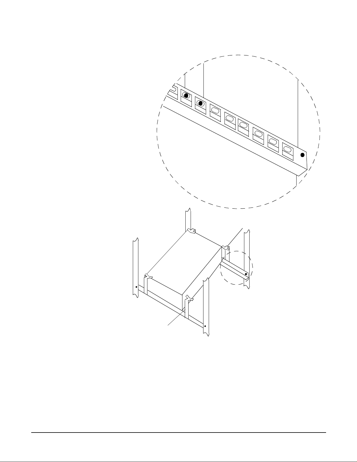
Installing HyperFabric
Installing HyperFabric Switc hes
rack
front
h
c
t
i
w
s
f
o
t
n
o
r
f
bracket 3
Step 6. Tight e n all four screws in bracke ts 3 and 4.
bracket 4
rack
back
72
Chapter 3
Page 73

Installing HyperFabric
Installing HyperFabric Switches
Step 7. From the front of the rack, push the switch so that it barely touches brackets 3 and 4.
The figure below sh o ws how to m ove the switch to this pos ition.
bracket 2
bracket 4
rack
front
h
c
t
i
w
s
f
o
t
n
o
r
f
bracket 1
bracket 3
rack
back
Chapter 3
73
Page 74

Installing HyperFabric
Installing HyperFabric Switc hes
Step 8. On ce the switch is snug against brackets 3 and 4, push brackets 1 and 2 in towards the
switch, so that they are snug again st the switch. The figure below shows brackets 1 and
2 in this position.
bracket 1
rack
front
bracket 2
bracket 4
h
c
t
i
w
s
f
o
t
n
o
r
f
rack
back
bracket 3
Step 9. Tight e n the four sc rews in bracke ts 1 and 2.
Step 10. For each port that will be connected to an HF1 adapter in an HP 9000 system, attach the
cable from th e corresponding adapter. Remember, your connections must be
copper-to-copper and fibre-to-fibre (incl uding cables).
Step 11. Connect the switch to the Ethernet ne twork.
74
Chapter 3
Page 75

Installing HyperFabric
Installing HyperFabric Switches
Step 12. Plug the switch’s power cord into the rack’s power distribution unit (PDU), if it has one.
Alternatively, you can plug a powe r cord that is com patible with your country’s
requirements i nto a power strip or outlet that you want to use for the switch. (In this
case, you are responsible for obtaining a compatible power cord.)
Step 13. Power on th e HF 1 swi t ch by pluggi ng t he power cord i nto the AC inlet on the back of the
switch. (T here is no po w e r switch.) O nce the power is on, th e “Power” LED shows solid
green.
Step 14. Check that, for each HF1 switch port that is conn ected to an HF1 ad apte r, the LED on
the port show s as solid green (see Figure 3-2 on page 68). This means the connection is
operational.
Step 15. Check that the “Ethernet” LED on the sw i tch’s Ethernet port is showing solid green
(connected) or fla shing gr een (Ethernet tr affic is flowing t o the s witch). S ee Fig ure 3-2 on
page 68 for the location of the LED.
For more detailed information abo ut th e sw itch ’s LEDs, see “HF1 Switch LEDs” on
page 114.
Step 16. If you want to install another HF1 switch, go back to step 1.
Otherwise, go to step 17.
Step 17. If you want to install one or more HF2 switches, go to the next section, “Installing the
HF2 Sw itch”.
Otherwise, go to Chapter 4, “Configurin g H ype rFabric,” on page 83.
Chapter 3
75
Page 76

Installing HyperFabric
Installing HyperFabric Switc hes
Install ing the HF2 Switch
This section contains information for installing an HF2 switch.
The front of the HF2 switch has a flange—or “wing”—on each side, with two holes for
attaching the switch to the rack. Note that the two figures below do not show the flanges.
Figure 3-3 belo w show s the front of the HF2 switc h with an A6388A H F2 8-port fibre
switch module ins talle d i n the switch’s expansion slot.
Figure 3-3 Front of HF2 Switch (A6388A Switch Module Installed)
Integrated Ethernet management
LAN card
Status
Status
Status
Power
A
B
Port
7
Port
15
Ethernet
Port
Main
Port
6
Port
14
Ethernet
Port
Port
5
Port
13
Aux
Label showing
Ethernet MAC
address
Port
4
Port
12
Port
Port
11
3
Port LED
colors and
meanings
legend
Port
2
Port
10
Integrat ed 8-port
fibre card
Port
1
Port
9
A6388A HF2 8-port fibre
switch module in
expansi on slot
Figure 3-4 belo w show s the front o f the HF2 switc h with an A6389A H F2 4-port coppe r
switch module ins talle d i n the switch’s expansion slot.
Port
0
Port
8
76
Chapter 3
Page 77

Installing HyperFabric Switches
Figure 3-4 Front of HF2 Switch (A6389A Switch Module Installed)
Installing HyperFabric
Port
Port
fibre card
2
9
Integrated 8-port
Port
1
Integrated Ethernet management
LAN card
Status
Status
Status
Power
A
B
Port
7
Ethernet
Port
Main
Port
6
Port
11
Ethernet
Port
5
Port
Aux
Label showing
Ethernet MAC
address
Port
4
Port
10
Port
3
Port LED
colors and
meanings
legend
A6389A HF2 4-port copper
switch module in
expansion slot
You can install t he HF2 switch in one of these two ways:
• Using the rail kit that is shipped with the switch (see the next section, “With the Rail
Kit”). Not e that HP str o ngly reco m me nd s in stalling the HF2 switch this way.
Port
0
Port
8
• Attaching the swit ch direc tly to the rack ( se e “Without the Rail Ki t” on page 81).
Chapter 3
77
Page 78

Installing HyperFabric
Installing HyperFabric Switc hes
With the Rail Kit
HP recommen d s that you install the HF2 switch using th e rail kit that is shipped with
the switch. The rail ki t inclu des two adjust able rails, screws, nut s, and washers.
To install the HF2 switch, you need eight screws and four nuts. Use the square cage nuts
if you are installing the HF2 switch in a square-hole rack. Use the u-type clip nuts if you
are installing the HF2 switch in a round-hole rack.
Figure 3- 5 sho w s var iou s p art s that ar e ship p ed wit h the rail kit.
Figure 3-5 Parts of the R ail Kit
78
The rail kit does not include hold-down brackets for the rear of the switch . HP does not
recommend trans p orting the rack with the switch ins talle d . HP re com m end s th at two
people install the HF2 switch.
Installing the HF2 Switch With the Rail kit
When you install the HF2 switch, you must put the front of the switc h—the end with the
flanges (“wings”)—at the back of the rack. To install the HF2 switch using the rail kit ,
complete the foll ow ing steps:
Step 1. P re p a re t he rack for rail and switch instal la t io n.
Step 2. Re mo ve all the scr ew s if you receive the rail kit with all ten screws secured in to the
rails.
Chapter 3
Page 79

One end of each rail has six screw-holes (End-A), the other end has two screw holes
(End-B). Figure 3-6 shows both the ends of t he rail.
Figure 3-6 The Ends of the Rail Kit
Installing HyperFabric
Installing HyperFabric Switches
Step 3. Orient the rails so that End-A faces the back of the rack and aligns with the front end of
the switch with flanges.
Step 4. Loosen the wing nuts on each rail and adjust the length of each rail to fit th e length of
the rack. End A mounts inside the rack colum n, and End-B moun ts o utsi de the rack
column.
Step 5. Tighten the wing nuts on each rail after you have adjusted the length properly.
Step 6. Ins tall and se cure the rails in the rack , u sing two screws per rail. Do not se cure End-A .
To secure End- B, com plete the fo ll o wing steps :
1. If you have sq uare-hole rac k s, affix two cage nuts inside each rack column. Align
these cage nuts with th e tw o h oles in End - B of each rail. Secure the assembly with
two screws in End-B of each rail.
2. If you have round-hole racks, affix two clip nuts to each rack column. Align these clip
nuts with the two ho le s in End -B of each rail. Secur e th e assem bly with two screws
in End-B of each rail.
Step 7. To install the switch, co m ple te the follo w ing ste p s:
1. Orient the front end of the switch (the end with the flanges) toward the back of the
rack.
2. Place the switch on the rails and slide it in to the rack until the flan ges are snug
against the outside of the rack columns.
Chapter 3
79
Page 80

Installing HyperFabric
Installing HyperFabric Switc hes
NOTE HP recommends employing two people to suppor t the weight of the switch because
End-A of the rail is not ye t se cu red .
Step 8. Secure the switch and End-A of each rail by aligning the two holes in each flange with
the two holes in each rack column, and two of the holes in each rail. Secure the entire
assembly with two screws in each flange.
Step 9. At ta c h t he ca ble from the co rrespondi n g a d a p te r f o r e a ch p o rt t h a t i s co nnected to a
HyperFabric adapter in an HP 9000 system.
NOTE Your connections must be copper-to-copper and fibre-to-fibre (including cables).
Step 10. Connect the switch to the Ethernet ne twork.
Step 11. Plug the switch’s power cord in to the rack’s Power Distributio n Unit ( P DU) , if it has
one.
NOTE Ensure that you plug a power card that is compatible with your country’s specifications
in to a power strip or outlet th at you want to use for the switch. In such a scenario, you
are responsible for obtaining a compatible power cord.
Step 12. Power on th e HF 2 swi t ch by pluggi ng t he power cord i nto the AC inlet on the back of the
switch. (There is no power switch.)
Step 13. Once t h e power i s on, chec k t hese L E D s on the i ntegr ated Ethern et mana gement LAN
adapter card in the top slo t of the switch:
✓ The “Operating/Fault” LED shows s olid green.
✓ The “Power A” and “Power B” LEDs show solid green.
✓ The “Ethernet Port Main” and “Ethernet Port Aux” LEDs show solid green
(connected) or flashing green. This indic ate s that ethernet tra ffi c is flowing to the
switch. For information about locating the LE Ds, see Figure 3-3 on page 76 or
Figure 3-4 on page 77.
Step 14. On the integr ated 8-port fibre card in the middle slot of the switch, check wh ether the
LED for each switch port that is connect ed to an HF2 adapter shows solid green . If the
LED shows solid green, it means the connect i on is opera tion a l .
Step 15. On the switch module in the expansion slot i n the bottom slot of the swi tc h , ch eck
whethe r the LED for each switch po rt that is conn e cte d t o an HF 2 ad a p ter shows so li d
green. If th e LED shows solid green, it means th e connection is operational.
80
For more information about the switch’s LEDs, see “HF2 Switch LEDs” on page 118.
Repeat steps 1 to 16 to install another HF2 switch using the rail kit. For information
about installing an HF2 switch without using a rail kit, see “Without the Rail Kit” on
page 81.
Chapter 3
Page 81

Installing HyperFabric
Installing HyperFabric Switches
Without the Rail Kit
As mentioned e arli er, HP strongly recomme n ds insta lling the HF2 switch using th e ra il
kit (described in th e previous section, “With the Rail Kit” on page 78).
When you install the HF2 switch, you will be putting the front of the switch—the end
with the flanges (“wings”)—at the back of the rack. The steps for installing the HF2
switch without using the rail k it are as follows:
Step 1. P re p a re th e rack for swi tch i nstallat ion.
Step 2. Insert the HF2 switch into the rack, with the front of the switch snug against the back of
the rack.
Step 3. Align the two holes in each flange on the switch’s front with the holes in the rack frame.
Step 4. Fasten each flang e of the switc h to the rack by putti ng a scre w in each of the four hole s
in the flanges. Be sure to us e scre ws with o ve r-sized he ads.
Step 5. Tighten all of the screws so tha t the HF 2 swit ch is firm ly mounted in the rack.
Step 6. For each port that will be connected to an HyperFabric adapter in an HP 9000 system,
attach the cable from the correspondin g adapter. Remember, your connections mu st be
copper-to-copper and fi bre-to-fibre, including cables.
Step 7. Co nn ec t the swit ch to the E the r ne t ne twork.
Step 8. Plug the switch’s power cord into the rack’s power distribution unit (PDU), if it has one.
Alternatively, you can plug a powe r cord that is com patible with your country’s
requirements i nto a power strip or outlet that you want to use for the switch. (In this
case, you are responsible for obtaining a compatible power cord.)
Step 9. Power on the HF2 swit c h by pl ugging the power cord into the AC inlet on the ba c k of the
switch. (There is no power switch.)
Step 10. Once t h e power i s on, chec k t hese L E D s on the i ntegr ated Ethern et mana gement LAN
adapte r card (in the to p slot of the s wi tch):
✓ The “Operating/Fault” LED shows s olid green.
✓ The “Power A” and “Power B” LEDs show solid green.
✓ The “Ethernet Port Main” and “Ethernet Port Aux” LEDs are showing solid green
(connected) or fla shing green (Ethernet traffic is flowing to the switc h). See
Figure 3-3 or Figure 3-4 below for the locations of the LEDs.
Step 11. On the integrated 8-port fibre car d (in the middle slot of the switc h ), ch eck that for each
switch port that is conn ecte d to an HF2 ad ap ter, the LED on the port shows as solid
green (see Figure 3-3 on page 76 or Figure 3-4 on page 77). This means the connection is
operational.
Step 12. On the switch module in the expansion slot (the bottom slot of the switc h), chec k that for
each swi tch port tha t i s co nnected t o a HyperFabric ada p t e r, the LED on the port sh ow s
as solid green (see Figure 3-3 on page 76 or Figure 3-4 on page 77). This means the
connection is operation a l .
Chapter 3
For more detailed information abo ut th e sw itch ’s LEDs, see “HF2 Switch LEDs” on
page 118.
Step 13. If you want to install another H F2 switch without using the ra il kit, go to step 1.
81
Page 82

Installing HyperFabric
Installing HyperFabric Switc hes
If you want to install another HF2 switch using the rail kit, go to “With the Rail Kit” on
page 78.
Otherwise, go to Chapter 4, “Configurin g H ype rFabric,” on page 83.
82
Chapter 3
Page 83

4 Configuring HyperFabric
This chapter contains the following sectio ns th at d es cribe conf igu rin g HyperFabric:
•“Configur atio n Ov e rvie w ” on page 85
•“Informatio n You Need” on page 86
•“Doing the Conf igu ration” on page 91
Chapter 4
83
Page 84

Configuring HyperFabric
•“Deconfiguring a Hyper Fabric Adapter with SAM—H P-UX 11.0 and 11i 0nly” on
page 96
•“Configuring the HyperFabric EMS Monitor” on page 97
•“Configuring HyperFabric with MC/ServiceGuard” on pag e 98
84
Chapter 4
Page 85

Configuring HyperFabric
Configuration Overview
Configuration Overview
You do not need to configure the HyperFa b ric swit ch because the HyperFabric
management proces s performs automatic routing and configuring for the switch. So,
configuring HyperFabric consists only of creating the HyperFabric
/etc/rc.config.d/clic_global_conf global configu rat io n fi le on each node in th e
fabric. The configuration file contains the following information:
• The IP addresses and subnet mask of the HyperFabric adapters installed in the
node.
• Fo r each Hyper Fabric switch in the fabric—th e sw itch ’s IP address, and the MAC
address of the switc h’s Ethernet port. Note that this applies only if you enable switch
management. Also note that you cannot enable switch management through
SAM—yo u must u se the clic_init command.
• The IP multicast address that all the switches and nodes in the fabric will register to
(if you are going to enable switch managemen t).
• The IP address of the local node’s Ethern et LAN interface. This LAN interface must
be on the same subnet as the Ethernet port(s) of the HyperFa b ric switc h (es ) (if you
are going to enable switch ma nag eme n t) . (No te that a nod e mig ht have multiple
LAN interfaces.)
• Whether the node can interop erate with nod es that are us ing an y HP-U X 10.20
version o f H yp e rFabric, an y HP - U X 11 . 0 HyperFabric versio ns e arlier than
B.11.00.11 or any HP-UX 11i HyperFabric versions earlier than B.11.11.01.
NOTE We recommend tha t yo u d o not enable switch managemen t.
You can create the global configu ra tio n file by eith er ( 1) run ning the clic_init
command or (2) using SAM (on HP-UX 11.0 and 11i only) to configure each HyperF abric
adapter.
clic_init and SAM also put the necessary entries into the following three files:
• The system /etc/rc.config.d/netconf file.
IMPORTANT: In this file, clic_init and SAM add some HyperFabric-related lines
that end with the characters #clic. These lines are used by the HyperFabric
software—and are not comments—so do not remove them from the file.
• The system /etc/rc.config.d/ clic_g lo bal_co n f file.
• The /etc/rarpd.conf (Reverse Address Resolution Protocol [RARP]) support file.
This file i s used in the managemen t of the HyperFabric switches (if you are going to
enable switch management).
The clic_init command is described in “Using the clic_init Comm and” on page 92.
Using SAM to configure an adapte r is described in “Using SAM—HP-UX 11.0 and
HP-UX 11i” on page 94.
Chapter 4
After you hav e us e d th e clic_init comm and o r S AM , yo u ca n co nf ig ure HyperFabric
with M C /Servi ceGuard , if nece s sa ry. See “C o nfiguring HyperFabric with
MC/ServiceGuard” on page 98 for more information.
85
Page 86

Configuring HyperFabric
Information You Need
Information You Need
When you run the clic_init command or use SAM for configuration, you have to
prov ide certain co nfiguration information. So, bef o re you run clic_init or use SAM,
you should get the foll ow ing information:
❏ For each node in the fabric, determine if that node will n eed to inte rop erate with
other nodes that are using; any HP-UX 10.20 versio n of HyperFabric, any HP-UX
11.0 HyperFabric versions earlier than B.11.00.11 or any HP-UX 11i HyperFabric
versio ns e a rlier than B.11.11.01.
❏ For each HyperFabri c adap te r ins talled in the lo cal node:
✓ The adapter’s IP address.
IMPORTANT: The last 10 bits of each adapter’s IP address must be unique
throughout th e entire fabric. An d, remember that the last part of the address
cannot b e 0 (that is, the IP address cannot be n.n.n.0). Also, note that
HyperFabric converts these 10 bits to a decimal value called the Virtua l Route
IDentifier (VRID), which is used in some HyperFabric command input and
output.
✓ The subnet ma sk. When you run clic_init or use SAM, if you do not specify a
value for thi s, a default subnet mask i s ch os en b ased on the adapter’s IP address.
When clic_init begins to prom p t yo u f o r the inf o rm ation for each ad ap te r, it
assigns an ID (for example, clic0) to that adapter and displays it as part of the first
prompt. If you use SAM, it assigns the adapter an ID and displays it in the “Adapter
Name” column of the “Configure HyperFabric Adapter” screen. Note that you can
also determine an adapter ’s ID by running the clic_stat command (see “The
clic_stat Comma nd” on page 91). You should note each adapter’s ID, be ca use it is
used as input to other Hy perFabric command s.
❏ For each HyperFabric switch in the fabric (if you are going to enable switch
management):
✓ The IP address of the switch.
✓ The MAC address of the switch’s Ethernet port. If you do not already know the
switch’s MAC address, it is printe d on a label on the back of the HF switch and
on the front of the HF2 switch.
IMPORTANT: Remember, you cannot enable s witch management through
SAM—yo u must u se the clic_init command.
When clic_init begins to prompt you for the information for each switch, it assigns
an ID (for example, sw_clic0) to that switc h and d isp lays it as pa rt of the first
prompt. Note that you can also deter mi ne a switc h’s ID by ru nning the clic_stat
command (see “The clic_stat Command” on page 91). You should note each s witch’s
ID, because it is used as input to other HyperFabric commands.
86
❏ F or t he entir e fabr i c, you need the IP multicast address tha t all the switc hes and
node s in the fabric will register to. The add r e ss must be a clas s D address. Note that
if you do not have sw itch m a n a gem e nt enabled, you do not ne ed this informatio n
(clic_init will not prompt you for it).
Chapter 4
Page 87

Configuring HyperFabric
Information You Need
❏ For each node in the fabric, you need the IP address of the node’s Ethernet LAN
interface that is on th e same subnet as the sw itches. (As mention ed earlier, a node
might have multiple L A N interfac e s.) Note that if you do no t have sw itch
managem e nt ena bled, you do not need this information (clic_init will not prom pt
you for it).
As stated earlier, we recommen d that you do not enable switch management.
IMPORTANT Y ou should also check your /etc/hosts file—when you are using files for host name look
up—to ensure that the entries for all of the systems a r e i n the correct format: the o ffi ci al
host name, which is the full domain extended host name, and any alias names. For
example:
IP_address bently6.corp3.com bently6
IP_address bently4.corp7.com test1
IP_address bently2.corp4.com test3
Chapter 4
87
Page 88

Configuring HyperFabric
Information You Need
Configuration Information Example
F or this exampl e, we have added some “dummy” (that is, not valid) addresses to the
components in Figure 4-1, Map for Configuration Information Example, below. The
“dummy” addresses are used only t o show the flow of the information provided as input
to the clic_init command and SAM. Do not try to use these addresses in your
configuration.
Figure 4-1 Map for Configuration Information Example
Ethernet LAN
Switch ID: sw_clic0
IP address: 193.0.0.20
Ethernet MAC address:
00:60:b0:d0:02: 57
IP multicast address:
226.10.1.1
HF
adapter 0
Adapter ID:
clic0
IP address:
192.0.0.1
subnet mask:
255.255.255.0
S
node A
HF
switch 0
Adapter ID:
clic1
IP address:
192.0.8.3
subnet mask:
node A
255.255.255.0
HF
adapter 1
HF
switch 1
HF
adapter 0
Adapter ID:
clic0
IP address:
192.0.0.2
subnet mask:
255.255.255.0
Switch ID: sw_clic1
IP address: 193.0.0.21
Ethernet MAC address:
00:60:b0:d0:02: 56
IP multic as t ad dre ss :
226.10.1.1
HF
adapter 1
Adapter ID:
clic1
IP address:
192.0.8.4
subnet mask:
node A
255.255.255.0
node B
88
lan0 lan0
IP address: 193.0.0.10 IP address: 193.0 .0.11
S
Using the config uration information in Figure 4-1 above, the information you wou ld
specify when you run clic_init or S AM on each of the node s i s l i s ted be l o w. Note that
this example is not an exact depiction of the prompts produced by clic_init nor the
fields in SAM, but merely an example of the flow of information input. Also , remember
that you should not try to use the “dummy” addre sse s in your actual configuration .
On nod e A:
1. How many HyperF abric adapters are installed on the node?
2. Do yo u want this node to interopera te with nodes running any HyperFabric 10.20
version or HyperFabric versions earlier than B.11.00.11 or B.11.11.01?
3. W hat is th e IP addr ess o f the first ad apte r (clic0)? (192.0.0.1)
Chapter 4
Page 89

Configuring HyperFabric
Information You Need
4. W hat is the subnet mask of the first adapte r? (255.255.255.0)
If you do not specify a value for this, a default mask is chosen. Y ou will most likely
just accept the default. However, in this example, we are showing a value for the
subnet mask just to illustrate the correlation between the “du mmy” in for matio n in
Figure 4-1 and wh ere that infor m ation is spe ci fied or gener a ted durin g clic_init
and SAM.
5. What is the IP address of the sec ond ada pte r (clic1)? (192.0.8.3)
6. What is the subnet mask of the sec on d a da pter? (255.255.225.0)
7. Do you want to enable switch m a nagement? Rem em b e r, you cannot enabl e sw itch
managem e nt thr o ugh SAM (you mus t use the clic_init command).
As stated earlier, we recommend that you do not enable switch management.
However, if you do enable it, you must provide the information in items 8 through 14:
8. If switch management has been enabled, how many switches will be configured? As
stated earlier, we recommend that you do not enable switc h management.
9. What is the IP address of the first switch (sw_clic0)? (193.0.0.20)
10. What is the E thernet ha rd wa re a d d re s s of the first s witch? (0060b0d00257)
11. What is the IP address of the second switc h ( sw_clic1)? (193.0.0.21)
12. What is the Ethernet hardware address of the second sw itch ? (0060b0d00256)
13. What is the Multicast address for the switches to use? (226.10.1.1)
14. What is the IP address for the LAN card on the same subnet as the switch es?
(193.0.0.10)
(Looking at Figure 4-1, this is the IP address for lan0 on node A.)
On node B:
1. How many HyperF abric adapters are installed on the node?
2. Do yo u want this node to interopera te with nodes running any HyperFabric 10.20
version or HyperFabric versions earlier than B.11.00.11 or B.11.11.01?
3. W hat is th e IP addr ess o f the first ad apte r (clic0)? (192.0.0.2)
4. W hat is the subnet mask of the first adapte r? (255.255.255.0)
If you do not specify a value for this, a default mask is chosen. Y ou will most likely
just accept the default. However, in this example, we are showing a value for the
subnet mask just to illustrate the correlation between the “du mmy” in for matio n in
Figure 4-1 and wh ere that infor m ation is spe ci fied or gener a ted durin g clic_init
and SAM.
5. What is the IP address of the sec ond ada pte r (clic1)? (192.0.8.4)
Chapter 4
6. What is the subnet mask of the sec on d a da pter? (255.255.225.0)
7. Do you want to enable switch m a nagement? Rem em b e r, you cannot enabl e sw itch
managem e nt thr o ugh SAM (you mus t use the clic_init command).
As stated earlier, we recommend that you do not enable switch management.
However, if you do enable it, you must provide the information in items 8 through 14
below.
89
Page 90

Configuring HyperFabric
Information You Need
8. If switch management has been enabled, how many switches will be configured? As
stated earlier, we recommend that you do not enable switc h management.
9. What is the IP address of the first switch (sw_clic0)? (193.0.0.20)
10. What is the E thernet ha rd wa re a d d re s s of the first s witch? (0060b0d00257)
11. What is the IP address of the second switc h ( sw_clic1)? (193.0.0.21)
12. What is the Ethernet hardware address of the second sw itch ? (0060b0d00256)
13. What is the Multicast address for the switches to use? (226.10.1.1)
14. What is the IP address for the LAN card on the same subnet as the switch es?
(193.0.0.11)
(Looking at Figure 4-1, this is the IP address for lan0 on node B.)
90
Chapter 4
Page 91

Configuring HyperFabric
Doing the Configuration
Doing the Configuration
As explained in “Configur ation Over view” on page 85, you must crea te the global
configuration file (/etc/rc.config.d/clic_global_conf) on each node in the fabric.
This consists mostly of specifying HyperF abric adapter-related information. (Note that if
you are also going to enable switc h manag e m ent—which we do not reco m m e nd
doing—you need to specify additional configuration information.)
NOTE Specifying configuration information adds or changes only the addresses and other
information in the global co nfiguration file, based on the information you supply. It does
not perform any operations to check the relationships between that information and any
physical connections within the fabric.
You nee d to create the glo bal con fi gur atio n file in th e fo llowing situations:
• You have just in stalled the HyperFabric hard ware and softw a re on the system.
• You want to change the information in the HyperFabric global configuration file (see
the Note above).
IMPORTANT Creating the global confi guration file also modifi es the /etc/rc.config.d/netconf file,
adding some HyperFabric-related lines that end with the characters #clic. These lines
are used by the HyperFabric software—and are not comments—so do not remove them
from the file.
You can create the global configuration file by using (1) the clic_init command
(described in the next section, “Using the clic_in it Comma nd ”) or (2) SAM (described in
“Using SAM—HP-UX 11.0 and HP-UX 11i” on page 94). You cannot enable card pair or
switch man age m e nt through SAM (yo u must use the clic_init command).
Chapter 4
91
Page 92

Configuring HyperFabric
Doing the Configurat ion
Using the clic_init Command
Run the clic_init command to create the global configuration file.
IMPORTANT If the global configuration file already exists and you are running clic_init again (to
change the file), you hav e the option of retain ing or modify i ng t he exi sti n g configuration
information, in addition to adding new information pertaining to new hardware.
Also, once you’ve completed your changes an d clic_init ends its proc es sin g, you mu st
stop HyperFabric (by running the clic_shutdown command or using SAM) and then
start HyperFabric (by running the clic_start command or using SAM). Otherwise,
your configuration information changes will not take effect. See “Stopping Hyper Fabric”
on page 99 and “Starting HyperFabric” on page 85 for more information.
If you include /opt/clic/bin in your PATH statement, you can run the command as it is
shown below. Otherwise, you must include /opt/clic/bin as part of the co mmand name
(that is, /opt/clic/bin/clic_init).
You must be logged in as root to run this command .
The syntax is as follows:
clic_init [-c] [-?]
where
• -c specifies that you want to create the global con f i gurat i on file. You are prompted
for the i nformation des cribed in “Information You Need” on page 86. Note that if the
global configuration file already exists (for example, when you are adding an adapter
to an existing fabric), clic_init prompts you with the existing configuration
information. As you are prompted with each piece of informati on, you can then
confirm that you want to keep it or you can change it.
• -? displays the on line he lp for clic_init.
If you do not specify any of the abov e parameters, the on line help for clic_init is
displayed.
After you have enter ed th e inform atio n for all the adap ters in the node and all of the
switches (if any) in the fabric, a summ ar y o f the configuration informa tio n is d isplaye d .
Once clic_init has finished, you do one of the following things:
• If yo u want to configure HyperFabric with MC/ServiceGuard, comp lete the
configuratio n described in “Configuring HyperFabric with MC/ServiceGuard” on
page 98, th e n run clic_start or use SAM to start HyperFabric.
• If you have just created the global co n f igu ratio n file on the lo cal nod e for the first
time (and you are not configuring MC/ServiceGuard), run clic_start or use SAM to
start HyperFabric.
92
• If you have just c hanged an existing confi guration file on the node, run
clic_shutdown or use SAM to stop HyperFabric, and then run clic_start or u se
SAM to start HyperFabric. Until you do those two things, your configuration changes
will not take effect.
See “Stopping HyperFabric” on page 99 and “Starting HyperFabric” on page 85 for more
information.
Chapter 4
Page 93

Configuring HyperFabric
Doing the Configuration
Examples of clic_init
Some examples of using the clic_init com m a nd a re shown below.
• Example 1
To create the global configuratio n file on the loca l nod e, issue this com m and :
clic_init -c
• Example 2
To display the online help for the clic_init command, issue this command:
clic_init -?
or this command:
clic_init
Chapter 4
93
Page 94

Configuring HyperFabric
Doing the Configurat ion
Using SAM—HP-UX 11.0 and HP-UX 11i
This section d es cr ibe s ho w to use SA M to co nf ig ure H yp e rFabric.
IMPORTANT If the global configuration file already exists, and you are running SAM again (to change
the file), you can kee p or mod if y th e exis ting co nfiguration inform atio n, in ad di tion to
adding new information pertaining to new hardware.
Also, once you’ve completed your changes and SAM ends its processing, you must stop
HyperFabric (by running the clic_shutdown command or usin g SA M) and th en star t
HyperFabric (by running the clic_start com m a nd or usin g S AM ). O the r wise, your
configuration inf orm ation changes will not take effect. See “Stopping HyperFabric” on
page 99 and “Star tin g Hy perFabric” on page 85 for more info rmation.
To use SAM to create the global configuration file on an HP 9000 system running HP-UX
11.0 or 11i, follow these steps:
Step 1. Start SA M.
Step 2. Sele ct the “Networking and Communications” area.
Step 3. Sele ct “HyperFabric.”
All HyperFabric adapters installed in the system are listed; installed a dapt ers that are
not yet configured show Not Configured in the “Status” field.
Step 4. Highlight the adapter you want to configure.
Step 5. Pull d o wn th e “Actions” menu and select Configure Adapter.
Step 6. In the “Config ure HyperFabric Adapter” screen, spec ify inf o rmation for the follow ing
fields:
• Internet Address—Required. The IP address of the adapter.
• Subnet Mask—Optional. The adapter’s subnet m ask . If you d o not sp ecify this, a
default mask is chosen based on the adapter’s IP address.
• Interoperability Enabled—Required. Whether you want the adapter to be able to
interoperate with adapters that are using; any HP-UX 10.20 version of HyperFabric,
any HP-UX 11.0 HyperFabric versions earlier than B.11.00.11 or any HP-UX 11i
HyperFabric versions earlier than B.11.11.01. Note that if you select No, t he
HyperFabric software on the system will not be backwards compatible with previous
releases. This means you must updat e all of the other systems in the fabric t o the
version that is running on the system.
Default: No.
Step 7. Sele ct OK (remember, you cannot enable switch management within SAM).
94
Step 8. Exit SAM.
Once SAM has finished, you do one of the following things:
• If yo u want to configure HyperFabric with MC/ServiceGuard, comp lete the
configuratio n described in “Configuring HyperFabric with MC/ServiceGuard” on
page 98, th e n run clic_start or use SAM to start HyperFabric.
Chapter 4
Page 95

Configuring HyperFabric
Doing the Configuration
• If you have just created the global co n f igu ratio n file on the lo cal nod e for the first
time (and you are not configuring MC/ServiceGuard), run clic_start or use SAM to
start HyperFabric.
• If you have just c hanged an existing confi guration file on the node, run
clic_shutdown or use SAM to stop HyperFabric, and then run clic_start or u se
SAM to start HyperFabric. Until you do those two things, your configuration changes
will not take effect.
See “Stopping HyperFabric” on page 99 and “Starting HyperFabric” on page 85 for more
information.
Chapter 4
95
Page 96

Configuring HyperFabric
Deconfiguring a H yperFabric Adapter with SAM—HP-UX 11. 0 and 11i 0nly
Deconfig uring a HyperFabric Adapter with
SAM—HP-UX 1 1.0 and 11i 0n ly
To use SAM to deconfigure a HyperFabric adapter on an HP 9000 system runn ing
HP-UX 11.0 or 11i, follow these steps:
Step 1. Start SA M.
Step 2. Sele ct the “Networking and Communications” area.
Step 3. Sele ct “HyperFabric.”
All HyperFabric adapters installed in the system ar e liste d. Insta lled adapter s that are
configured show Configured in the “Status” field, and installed adapters that are not
yet configur e d sho w Not Configured in the “Status” field. Y ou can deconfigure only an
adapter with a status of Configured.
Step 4. Highlight the adapter you want to deconfigure.
Step 5. Pull d o wn th e “Actions” menu and select Deconfigure Adapter.
Step 6. In the po p-u p wind o w, if yo u want to d eco nfigure the adapter, select OK to confirm it.
If you do not want to deconf igu re the ad ap ter, select Cancel.
Step 7. If you selected OK , the entry for the adapter is deleted from the HyperFabric
configuration files (/etc/rc.config.d/clic_global_conf and
/etc/rc.config.d/netconf).
If you selected Cancel, yo u re ma in in the m ain “HyperFabric Configuration” scr e en .
Step 8. Exit SAM.
96
Chapter 4
Page 97

Configuring HyperFabric
Configuring the HyperFabric EMS Monitor
Configuring the HyperFabric EMS Monitor
Starting with the December 2000 releases B.11.00.11 and B.11.11.01,
the HyperFabric Event Monitoring Service (EMS) monitor allows system administrators
to separately monitor each HyperFabric adapter on every node in the fabric, in addition
to monitoring the e ntir e Hype r Fabric subsystem.
The monitor can inform the user if the resou rc e be ing monitored is UP or DOWN . The
administra tor d efin es the cond ition to trigger a notifica tio n (usu ally a change in
interface status). Notification can be accomplished with a SNMP trap or by logging into
the syslog file with a choice of s everity, or by email to a user defined email address.
To configure the HyperF abric EMS monitor, it is necessary to have the EMS HA monitor
product installed (Produ ct Numbe r B7609BA). This p roduc t is available o n the
applications CD media.
Use SAM to initiate monitoring of any particular HyperFabric resource. following the
procedure outlined below:
1. Star t SAM (U se the online help at any time for details)
2. Select “Resource Management”
3. Select “Event Monitoring Service”
4. Select “Action” and “Add Monitoring Request”
5. Se le ct th e loc ation /n et/i nte r fa ces/ clic (class for Hy per Fabric resources )
6. Se le ct a resou rc e instance (either all instances o r a specific in stan ce from the list)
7. Validate your ch oice by clicking on OK at the bottom of the screen
8. A Monitoring Request Parameters window opens, showing the resource and its
status (if All instances have been selected, then no value is displayed)
9. De f ine a co ndition that will trigger a notific a tion ( fo r inst anc e, “When V alue is”,
“equal to”, “UP”)
10. Define a polling interval (default is 300 seconds)
11. Define a way of notification: SNMP trap, log in syslog with a choice of severity, or
email to a user defined email ad d ress
12. Validate by pressing OK
NOTE Although EMS is able to monitor each HyperFabric adapter on every node in the
fabric, as well as the entire HyperFabric subsystem, EMS is not able to monit or
HyperFabric switches.
Chapter 4
For more detailed information on EMS, including instructions for implementing this
feature, see the EMS Hardware Monito rs Users Guide Part Number B6191-90028
September 2001 Edition.
97
Page 98

Configuring HyperFabric
Configuring Hyper Fabric with MC/ServiceGuard
Configuring HyperFabric with MC/ServiceGuard
HyperFabric supports the MC/ServiceGuard HA product.
NOTE If you plan to configure Hy p erFabric with MC/Se rv iceGu ard , pl ea se read this sect io n.
Otherwise, skip this section and go on to the next chapter, Chapter 4, “Managing
HyperFabric,” on page 83.
MC/ServiceGuar d lets you create H A clusters of H P 9000 server systems. Within the
cluster, MC/ServiceGuard allows you to group your application services (individual
HP-UX processes) i nto pa ckages. In the event of a si ngl e s ervice , n ode, network, or other
resource failure, MC/ServiceGuard can transfer control of the package to another node in
the cluster, allowing servi ces to rem ain available with minimal inte r ru p tion.
CAUTION When applications use HMP to communicate between HP 9000 nodes in a HyperFabric
cluster, the EMS monitor in conjunction with MC/ServiceGuard can be configured to
identify node failure and automatically fail-over to a functioning HP 9000 node.
Although failure of an adapter card or a link will be detected, there will not be automatic
fail-over if an adapter card or a link fails. See “Features” on page 25 for details on
features available when HMP applications are run over HyperFabric.
MC/Se rviceGuard directly monito rs cluster nodes, LAN inter f a ce s, a nd se rvices, whic h
are the indiv idual processes within an application. In addition , specialized monitors
might be supplied by the developer s of other compon ents. The HyperFabric mon itor is
supplied with the HyperFabric product and is installed with it. To use the HyperFabric
monitor with MC/ServiceGuard, you configure the monitor as an MC/ServiceGuard
package dependen cy.
Although HyperFabr ic can be used by an application within a package to communicate
with other nodes, it is not possible to use HyperFabric as a heartbeat LAN. So, in a
package co ntrol script, do not specif y H y p e rFabric IPs/subnets in the lines that contain
the keywords IP[n] and SUBNET[n]. Also, cmquerycl will not “discover” and report
HyperFabric IPs and subnets.
After you have configured HyperFabric as a package dependency, MC/ServiceGuar d’s
package m a nager calls the Event Monitoring Service (EMS) to launch an external
monitor for Hype rFabric. The package will no t start unless the monit or re po rts that
HyperFabric is available, and the package will fail when HyperFabric’s status is DOWN
(that is, when all HyperFabric adapters on a node become non-functional).
Compl e te in st r u c t io ns f o r configur ing MC/Ser vi c e G uard cluste rs and packag es are
provided in Managing MC/Serv i ce Guard.
Figure 4-2 below shows a HyperFabric switch configuration with MC/ServiceGuard. This
example shows a four -node c onfi guration with two HyperFabric switches, and redundant
heartbeat Eth ernet L A N s.
98
Chapter 4
Page 99

Configuring HyperFabric
Configuring HyperFabric with MC/ServiceGuard
NOTE Because the HyperFabric network does not currently support MC/ServiceGuard
heartbeat connect i ons, you must use an alternative type of connecti on for the heartbeat,
such as FDDI, Token Ring, 100BaseT, or Ethernet (as shown in Figure 4-2 below).
Chapter 4
99
Page 100

Configuring HyperFabric
Configuring Hyper Fabric with MC/ServiceGuard
Figure 4-2 An MC/ServiceGuard Configuration (with Two HyperFabric Switches)
Ethernet Heartbeat LAN 1
Ethernet Heartbeat LAN 0
node A
HF
adapter 1
HF
adapter 0
Etherne t Port
node C
HF
adapter 0
HF
adapter 1
HF
switch 0
HF
adapter 0
HF
adapter 1
HF
switch 1
HF
HF
adapter 0
node B
Ethernet Port
node D
adapter 1
100
S
S
How HyperFabric Handles Adapter Failures
HyperFabric adapters are handled differently than othe r types o f netwo rkin g adap te rs
(such as Ether net, FDDI, and Fibre Chan nel) in the MC/ServiceGuard environment. In
the non-Hyper Fabric cases, two network link s are in a nod e, and one will be activ e and
one will be idle or in standby. I n the case o f an active lin k failure, MC/ServiceGua rd is
notified and the netwo r k tra f fic is switc hed to the stan d by ad ap ter (which then becomes
active).
However, in the case of HyperFabric, if two adapters are in a node, both will be active. If
one active HyperFabric adapter fails, its networ k tr affic is switched to the other active
HyperFabric adapter in the node. (Throughput might be slower because only one active
Chapter 4
S
S
 Loading...