

Page 1

HPE FlexNetwork HSR6800 Routers
Installation Guide
Part number: 5200-3525
Document version: 6W105-20170412
Page 2

© Copyright 2015, 2017 Hewlett Packard Enterprise Development LP
The information contained herein is subject to change without notice. The only warranties for Hewlett Packard
Enterprise products and services are set forth in the express warranty statements acco mpanying such
products and services. Nothing herein should be construe d as constituting an additional warranty. Hewlett
Packard Enterprise shall not be liable for technical or editorial errors or omissions co ntained herein.
Confidential computer software. V alid license from Hewlett Packard Enterprise required for possession, use, or
copying. Consistent with FAR 12.211 and 12.212, Commercial Computer Software, Computer Software
Documentation, and T e chnical Data for Commercial Items are licensed to the U.S. Government under vendor’s
standard commercial license.
Links to third-party websites take you outside the Hewlett Packard Enterprise website. Hewlett Packard
Enterprise has no control over and is not responsible for information outside the Hewlett Packard Enterprise
website.
Acknowledgments
Intel®, Itanium®, Pentium®, Intel Inside®, and the Intel Inside logo are trademarks of Intel Corporation in the
United States and other countries.
Microsoft® and Windows® are either registered trademarks or trademarks of Microsoft Corporation in the
United States and/or other countries.
Adobe® and Acrobat® are trademarks of Adobe Systems In corporated.
Java and Oracle are registered trademarks of Oracle and/or its affiliates.
UNIX® is a registered trademark of The Open Group.
Page 3

Contents
Preparing for installation ···································································· 1
Safety recommendations ············································································································· 1
Safety symbols ··················································································································· 1
Electricity safety ·················································································································· 1
Laser safety ······················································································································· 1
Router moving ···················································································································· 2
ESD prevention ··················································································································· 2
Examining the installation site ······································································································· 3
Weight support ··················································································································· 3
Temperature and humidity ····································································································· 3
Altitude ······························································································································ 4
Cleanliness ························································································································ 4
Cooling system ··················································································································· 5
EMI ·································································································································· 6
Lightning protection ············································································································· 6
Space ······························································································································· 6
Power supply ······················································································································ 7
Installation accessories ··············································································································· 7
Installing the router ··········································································· 9
Installation flow ·························································································································· 9
Installing a cable management bracket ··························································································· 9
Installing the router in a 19-inch rack ···························································································· 10
Installing cage nuts to the rack ····························································································· 10
Attaching the mounting brackets to the router ·········································································· 11
Installing the router in a 19-inch rack ····················································································· 12
Grounding the router················································································································· 12
Installing a power supply ··········································································································· 13
Installing an MPU and a switching fabric module ············································································ 14
Installing an MPU ·············································································································· 14
Installing an SFE-X1 switching fabric module ·········································································· 14
Installing an LPU ····················································································································· 15
Installing a HIM ······················································································································· 16
Installing a MIM ······················································································································· 17
Installing a CF card ·················································································································· 17
Installing optional components ···································································································· 18
Installing an air filter ··········································································································· 18
Installing a lightning protector for a network port ······································································· 20
Connecting the AC power supply to a power strip with lightning protection ····································· 21
Installing a surge protector ·································································································· 22
Connecting the power cord ········································································································ 24
Connecting an AC power cord ······························································································ 24
Connecting DC power cords ································································································ 24
Connecting interface cables ····························································· 27
Connecting the AUX cable ········································································································· 27
Overview ························································································································· 27
Connecting the AUX cable ·································································································· 27
Connecting an Ethernet cable ····································································································· 28
Overview ························································································································· 28
Making an Ethernet cable ···································································································· 29
Connecting an Ethernet cable ······························································································ 29
Connecting a fiber cable ············································································································ 30
Transceiver module overview ······························································································· 30
Fiber cable overview ·········································································································· 31
Connecting a fiber cable ····································································································· 32
Connecting a T3 cable ·············································································································· 33
i
Page 4

Overview ························································································································· 33
Connecting a T3 cable ········································································································ 33
Accessing the router ······································································· 35
Login methods ························································································································ 35
Logging in through the console port ····························································································· 35
Setting up a configuration environment ·················································································· 35
Setting terminal parameters ································································································· 36
Powering on the router ·············································································································· 38
Verifying before power-on ··································································································· 38
Powering on the router ······································································································· 38
Displaying boot information ································································································· 38
Logging in to the router through Telnet/SSH ·················································································· 39
Logging in to the router through the AUX port ················································································ 40
Configuring basic settings ·········································································································· 40
Replacement procedures ································································· 41
Safety recommendations ··········································································································· 41
Replacing a power supply ·········································································································· 41
Replacing an MPU and a switching fabric module ··········································································· 41
Prerequisites ···················································································································· 41
Replacing an MPU ············································································································· 42
Replacing an SFE-X1 ········································································································· 42
Replacing an LPU ···················································································································· 43
Replacing a HIM ······················································································································ 44
Replacing a MIM ······················································································································ 44
Replacing a CF card ················································································································· 45
Replacing a transceiver module ·································································································· 45
Replacing a fan tray·················································································································· 46
Replacing a fan tray for an HSR6802/HSR6804 router ······························································ 46
Replacing a fan tray for an HSR6808 router ············································································ 47
Replacing an air filter ················································································································ 47
Replacing an air filter for an HSR6802/HSR6804 router ····························································· 48
Replacing an air filter for an HSR6808 router ··········································································· 48
Replacing a memory module ······································································································ 49
Memory module structure ···································································································· 49
Replacing a memory module ······························································································· 50
Hardware management and maintenance ··········································· 51
Displaying the hardware information of the router ··········································································· 51
Displaying the version information of the router ········································································ 51
Displaying the running statistics for the router ·········································································· 51
Displaying detailed information about a card ··········································································· 52
Displaying the electrical label data ························································································ 53
Displaying the CPU usage statistics ······················································································ 53
Displaying the MPU memory usage ······················································································· 54
Displaying the CF card information ························································································ 54
Displaying the fan operating status ························································································ 55
Displaying the power supply operating status ·········································································· 55
Displaying the alarming thresholds of a card ·················································································· 56
Port configuration and management ····························································································· 56
Configuring a combo interface ······························································································ 56
Displaying and verifying transceiver modules ·········································································· 57
Active and standby switchover for MPUs ······················································································· 58
Troubleshooting system exceptions ····························································································· 58
Configuring the exception handling methods ··········································································· 58
Displaying the exception handling method ·············································································· 59
Rebooting a card or router ········································································································· 59
Troubleshooting ············································································· 61
MPU failures ··························································································································· 61
RUN LED is off ················································································································· 61
ii
Page 5

RUN LED fast flashes ········································································································ 61
ALM LED is steady on or flashes ·························································································· 61
PALM LED is steady on ······································································································ 62
LPU failures ···························································································································· 62
RUN LED is off ················································································································· 62
RUN LED fast flashes ········································································································ 63
Power supply failures ················································································································ 63
Power LED is off ··············································································································· 63
Red power LED is on ········································································································· 64
Fan failures ···························································································································· 64
Fan tray is absent ·············································································································· 64
ALM LED is red ················································································································· 64
HIM/MIM failures······················································································································ 65
Configuration system problems ··································································································· 65
No terminal display ············································································································ 65
Garbled terminal display ····································································································· 65
No response from the serial port ··························································································· 66
Dealing with password loss ········································································································ 66
Examining the state of password recovery capability ································································· 67
Dealing with console login password loss when password recovery capability is enabled ·················· 68
Dealing with user privilege level password loss when password recovery capability is enabled ·········· 69
Dealing with password loss when password recovery capability is disabled ··································· 69
Cooling system failure ··············································································································· 70
Ethernet port failure ·················································································································· 71
HIM/MIM, cable, and connection failure ························································································ 71
Software upgrade failures ·········································································································· 72
No response from the serial port of the MPU ··········································································· 72
TFTP upgrade failure ········································································································· 72
FTP upgrade failure ··········································································································· 72
System software image file missing errors ····················································································· 73
Document conventions and icons ······················································ 73
Conventions ··························································································································· 73
Network topology icons ············································································································· 74
Support and other resources ···························································· 76
Accessing Hewlett Packard Enterprise Support ·············································································· 76
Accessing updates ··················································································································· 76
Websites ························································································································· 77
Customer self repair ··········································································································· 77
Remote support ················································································································ 77
Documentation feedback ···································································································· 77
Appendix A Chassis views and technical specifications ·························· 79
Chassis views ························································································································· 80
HSR6802 ························································································································· 81
HSR6804 ························································································································· 82
HSR6808 ························································································································· 83
Dimensions and weights ············································································································ 84
Power consumption ·················································································································· 85
Power supplies ························································································································ 86
AC power supplies ············································································································· 86
DC power supplies ············································································································ 87
Fan trays ································································································································ 89
MPUs ···································································································································· 90
Components ····················································································································· 92
Switching fabric module ············································································································· 94
SFE-X1 ··························································································································· 94
LPUs ····································································································································· 94
FIP-110 ··························································································································· 95
FIP-210 ··························································································································· 96
FIP-240 ··························································································································· 97
iii
Page 6

FIP-300 ··························································································································· 98
FIP-310 ··························································································································· 99
FIP-600 ························································································································· 101
SAP-48GBE ··················································································································· 102
SAP-24GBP ··················································································································· 102
SAP-48GBP ··················································································································· 103
SAP-4EXP ····················································································································· 104
SAP-20GE2XP ··············································································································· 105
SAP-28GE ····················································································································· 106
SPEs/OAPs ·························································································································· 107
HIMs/MIMs ··························································································································· 107
Transceiver modules ·············································································································· 108
Lightning protector for a port ····································································································· 108
Power strip with lightning protection ··························································································· 108
Surge lightning protector ·········································································································· 108
Appendix B LEDs ········································································· 109
MPU and switching fabric module LEDs ······················································································ 109
LPU LEDs ···························································································································· 111
FIP LEDs ······················································································································· 111
SAP LEDs ····················································································································· 114
SPE LEDs ···························································································································· 118
HIM/MIM LEDs ······················································································································ 119
Power supply LEDs ················································································································ 119
Fan LEDs ····························································································································· 120
Appendix C Arranging slots and numbering interfaces ·························· 123
Slot arrangement ··················································································································· 123
Available slots for cards ··········································································································· 124
Numbering interfaces ·············································································································· 125
Examples ····························································································································· 125
Example 1 ····················································································································· 125
Example 2 ····················································································································· 125
Appendix D Cable management ······················································ 126
General cabling requirements ··································································································· 126
Minimum curvature radius of cables ···················································································· 126
Minimum curvature radius of fibers ······················································································ 126
Labeling cables ····················································································································· 126
Cable management guidelines ·································································································· 126
Cable routing example ············································································································ 129
Appendix E Hardware compatibility matrixes ······································ 130
MPU and Comware compatibility matrix ······················································································ 130
LPU and Comware compatibility matrix ······················································································· 130
Index ························································································· 131
iv
Page 7

r
Preparing for installation
Safety recommendations
To avoid any equipment damage or bodily injury caused by improper use, read the following safety
recommendations before installation. Note that the recommendations do not cover every possible
hazardous condition.
Safety symbols
When reading this document, note the following symbols:
WARNING means an alert that calls attention to important information that if not understood or
followed can result in personal injury.
CAUTION means an alert that calls attention to important information that if not understood or
followed can result in data loss, data corruption, or damage to hardware or software.
Electricity safety
• Locate the emergency power-off switch in the room before installation. Shut the power off at
once in case accident occurs. Disconnect the power cord of the router if necessary.
• Use an uninterrupted power supply (UPS).
• Do not work alone when the router has power. Do not touch any power plug when it is
connected.
• Always make sure the power has been disconnected during installation and replacement.
Laser safety
WARNING!
• Do not stare into any fiber port when the router has power. The laser light emitted from the optical fiber
might hurt your eyes.
• Use fiber test equipment, rather than a microscope or magnifier to observe an operating fiber connector o
port when you test link connectivity or system parameters.
The routers are Class 1 laser devices.
When you connect an optical fiber, follow these guidelines:
• Some interface modules on the router provide shielded covers for the fiber ports (such as SFP
ports). Before using such fiber ports, remove the shielded covers. Keep the shielded covers
secure. When the fiber ports are not in use, install the shielded covers.
• Fiber connectors are fitted with dust caps. Keep the dust caps secure when the fiber connectors
are in use. Install dust caps when the fiber connectors are not in use to avoid damage to their
end face. Replace the dust cap if it is loose or polluted.
• Before connecting an optical fiber, use dust free paper and absolute alcohol to clean the end
face of the two fiber connectors. You can brush the end faces only in one direction.
• After a fiber is installed well, the bend radius must be not less than 10 cm (3.94 in).
• If the fiber has to pass through a metallic board hole, the hole must have a sleek and fully filleted
surface. (The filleting radius must be not less than 2 mm, or 0.08 in.) When passing through a
1
Page 8

r
metallic board hole or bending along the acute side of mechanical parts, the fiber must wear
jackets or cushions.
Router moving
CAUTION:
Do not hold the handle of the fan tray or power supply, the handle of the rear cover of the chassis, o
the air vents of chassis. Any attempt to carry the router with these parts might cause equipment
damage or even bodily injury.
When you move a router, follow these guidelines:
• Lift and put down the chassis slowly and never move suddenly.
• When you move a heavy router or multiple routers, use a pallet jack.
• Before moving the chassis, turn off the power switch and remove all cables, USB devices, and
mounting brackets.
• If the router needs to be moved over a long distance, remove all field replacement units (FRUs),
such as HIMs/MIMs, put them separately in anti-static bags, and install the filler panels supplied
with router.
• If the router needs to be moved over a short distance, make sure all FRUs are securely seated
in slots and the screws are fastened.
• Make sure the accessories of the router are not lost or damaged during router moving.
• Make sure the ground is dry and flat and anti-slip measures are in place.
• Keep the chassis and installation tools away from walk areas.
ESD prevention
CAUTION:
Make sure the resistance reading between human body and the ground is in the range of 1 to 10
megohms (Mohms).
To prevent electrostatic discharge (ESD), follow these guidelines:
• Make sure the router and the rack are reliably grounded.
• An anti-static floor is installed and reliably grounded.
• Take dust-proof measures for the equipment room.
• Maintain the humidity and temperature in the acceptable range.
• Always wear an ESD wrist strap and ESD cloth when touching a circuit board or transceiver
module.
• Place the removed CF card or LPU on an antistatic workbench, with the face upward, or put it
into an antistatic bag.
• Touch only the edges, instead of electronic components when you observe or move a removed
CF card or LPU.
To attach an ESD wrist strap:
1. Wear the wrist strap on your wrist.
2. Lock the wrist strap tight around your wrist to keep good contact with the skin.
3. Insert the ESD plug into the ESD socket.
4. Make sure the rack is reliably grounded.
2
Page 9
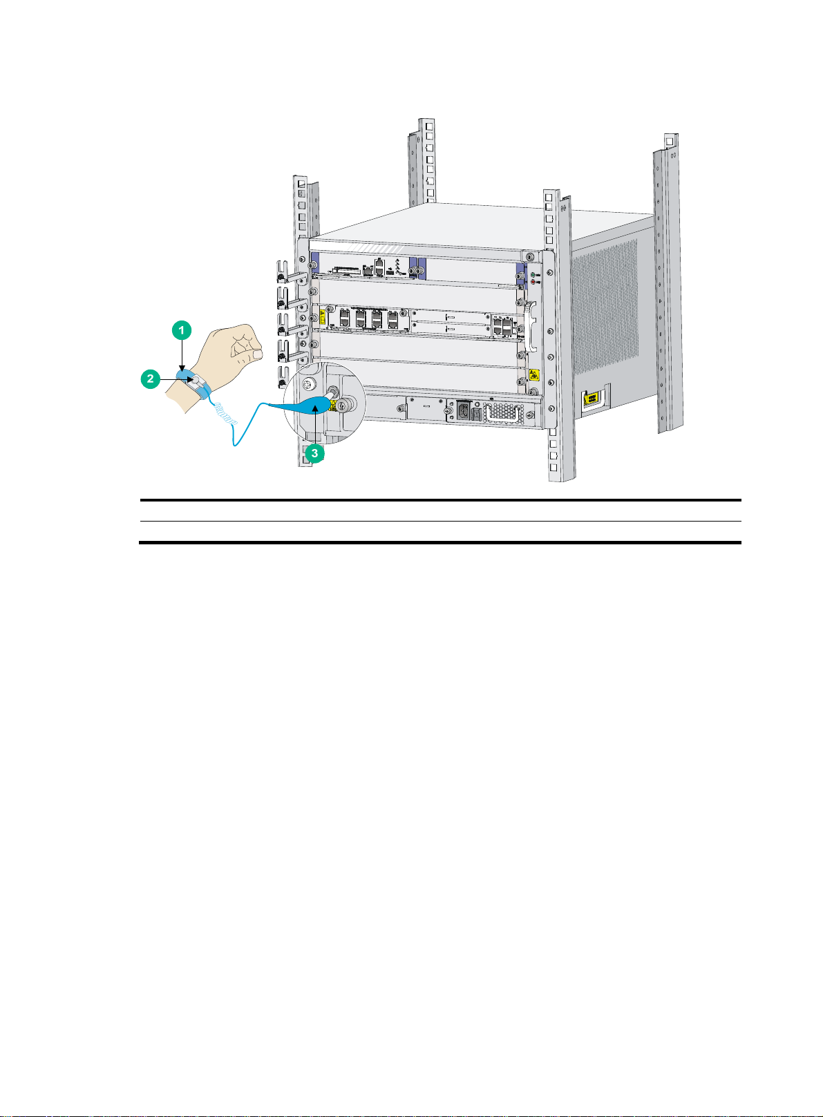
Figure 1 Attaching an ESD wrist strap
(1) ESD wrist strap (2) Lock
(3) ESD plug
Examining the installation site
The routers can only be used indoors. To make sure the router operates correctly and to prolong its
service lifetime, the installation site must meet the following requirements:
Weight support
Make sure the floor can support the total weight of the router and accessories (such as the rack and
HIMs/MIMs). For the weight of the router and accessories, see "Appendix A Chassis views and
cal specifications."
techni
Temperature and humidity
Maintain temperature and humidity in the equipment room in an acceptable range.
• Lasting high relative humidity can cause poor insulation, electricity leakage, mechanical
property change of materials, and metal corrosion.
• Lasting low relative humidity can cause washer contraction and ESD and bring problems
including loose screws and circuit failure.
• High temperature can accelerate the aging of insulation materials and significantly lower the
reliability and lifespan of the router.
For the temperature and humidity requirements of the router, see Table 1 an
3
d Table 2.
Page 10

Table 1 Temperature requirements
Item Temperature
Operating Temperature 0°C to 45°C (32°F to 113°F)
Storage Temperature –40°C to +70°C (–40°F to +158°F)
Table 2 Humidity requirements
Item Humidity
Operating humidity (noncondensing) 10% RH to 95% RH
Storage humidity (noncondensing) 5% RH to 95% RH
Altitude
Table 3 Altitude requirements
Item Altitude
Operating altitude –60 m (–196.85 ft) to 4 km (2.49 miles)
Storage altitude –60 m (–196.85 ft) to 4.5 km (2.80 miles)
Cleanliness
Dust buildup on the chassis might result in electrostatic adsorption, which causes poor contact of
metal components and contact points, especially when indoor relative humidity is low. In the worst
case, electrostatic adsorption can cause communication failure.
Table 4 Dust concentration limit in the equipment room
Substance Concentration limit (particles/m
Dust particles
NOTE:
Dust particle diameter ≥ 5 µm
The equipment room must also meet strict limits on salts, acids, and sulfides to eliminate corrosion
and premature aging of components, as shown in Tab l e 5.
Table 5
Harmful gas limits in an equipment room
Gas Max. (mg/m
SO2 0.2
H2S 0.006
NH
3
Cl
2
≤ 3 x 10⁴
(No visible dust on desk in three days)
3
)
0.05
0.01
3
)
4
Page 11
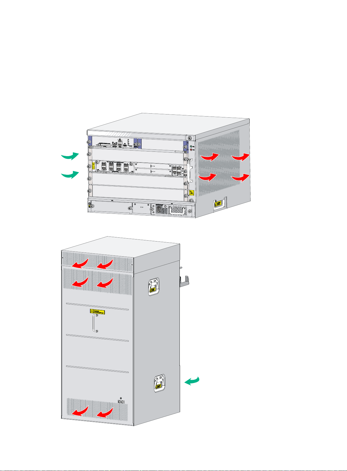
Cooling system
Fan trays of the routers are hot swappable and support automatic fan speed adjustment. To ensure
good ventilation, the following requirements must be met:
• Leave a minimum clearance of 10 cm (3.94 in) at the inlet and outlet air vents.
• The installation site has a good cooling system.
The HSR6802 and HSR6804 routers use the same airflow design.
Figure 2 Airflow through the HSR6804 chassis
Figure 3 Airflow through the HSR6808 chassis
5
Page 12

EMI
All electromagnetic interference (EMI) sources, from outside or inside of the router and application
system, adversely affect the router in the following ways:
• A conduction pattern of capacitance coupling.
• Inductance coupling.
• Electromagnetic wave radiation.
• Common impedance (including the grounding system) coupling.
To prevent EMI, use the following guidelines:
• If AC power is used, use a single-phase three-wire power receptacle with protection earth (PE)
to filter interference from the power grid.
• Keep the router far away from radio transmitting stations, radar stations, and high-frequency
devices.
• Use electromagnetic shielding, for example, shielded interface cables, when necessary.
Lightning protection
To protect the router from lightning, perform the following tasks:
• Make sure the grounding cable of the chassis is reliably grounded. For how to connect the
• Make sure the grounding terminal of the AC power receptacle is reliably grounded.
• Install a lightning arrester at the input end of the power supply to enhance the lightning
• Install a special lightning arrester at the input end of outdoor signal lines (for example, E1 line)
For how to install lightning protectors and surge protector, see "Installing a lightning protector for a
netwo
and Installing a surge protector."
Space
For easy installation and maintenance, follow these space requirements:
• Reserve a minimum of 1 m (3.28 ft) of clearance between the rack and walls or other devices.
• For heat dissipation, make sure the headroom in the equipment room is not less than 3 m (9.84
• Make sure the rack has enough space to accommodate the router. See Table 6 for
grounding cable, see "Grounding the router."
protection capability of the power supply.
to which interface modules of the router are connected to enhance the lightning protection
capability.
rk port," "Connecting the AC power supply to a power strip with lightning p
ft).
requirements. For more information about chassis dimensions, see "Appendix A Chassis views
and technical specifications."
rotection,"
rack
6
Page 13

Table 6 Router dimensions and rack requirements
Model Chassis dimensions Rack requirements
HSR6802
HSR6804
HSR6808
• Height—220 mm (8.66 in)/5 RU
• Width—436 mm (17.17 in)
• Depth—576 mm (22.68 in)
{ 480 mm (18.90 in) for the chassis
{ 95 mm (3.74 in) for the cable
management brackets at the chassis
front
{ 11 mm (0.43 in) for the grounding
screw at the chassis rear
• Height—308 mm (12.13 in)/7 RU
• Width—436 mm (17.17 in)
• Depth—576 mm (22.68 in)
{ 480 mm (18.90 in) for the chassis
{ 95 mm (3.74 in) for the cable
management brackets at the chassis
front
{ 11 mm (0.43 in) for the grounding
screw at the chassis rear
• Height—886 mm (34.89 in)/20 RU
• Width—436 mm (17.17 in)
• Depth—591 mm (23.27 in)
{ 480 mm (18.90 in) for the chassis
{ 102 mm (4.02 in) for the cable
management brackets at the chassis
front
{ 11 mm (0.43 in) for the grounding
screw at the chassis rear
• A minimum of 95 mm (3.74 in)
between the front rack posts and the
front door.
• A minimum of 481 mm (18.94 in)
between the front rack posts and the
rear door.
As a best practice, use a rack a
minimum of 0.8 m (2.62 ft) in depth.
• A minimum of 95 mm (3.74 in)
between the front rack posts and the
front door.
• A minimum of 481 mm (18.94 in)
between the front rack posts and the
rear door.
As a best practice, use a rack a
minimum of 0.8 m (2.62 ft) in depth.
• A minimum of 102 mm (4.02 in)
between the front rack posts and the
front door.
• A minimum of 490 mm (19.29 in)
between the front rack posts and the
rear door.
As a best practice, use a rack a
minimum of 0.8 m (2.62 ft) in depth.
NOTE:
The signal cables and power cords are routed through the front of the chassis. If you use power
cords that has a conductor cross-section area of a minimum of 16 sq mm (0.02 sq in), leave more
space between the front rack posts and the front door as appropriate.
Power supply
• Make sure the power supply system at the installation site is stable and meets the requirements
of the power supplies, including the rated input voltage.
• Select power supplies based on the power consumption of the cards and fan trays. For more
information about system power consumption and technical specifications of power supplies,
see "Appendix A Chassis views and te
Installation accessories
Table 7 Installation accessories
Product code Item Quantity
5185-8627 Console cable 1
chnical specifications".
7
Page 14
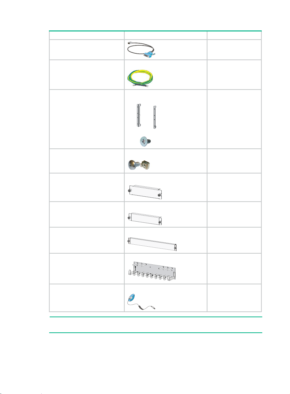
Product code Item Quantity
Grounding cable
5185-8507
• HSR6802: 5189-9473 and
5003-2441
• HSR6804: 5189-9472 and
5003-2440
• HSR6808: 5003-1608
• M6 cage nut:
5185-8965
• M6 screw:
5185-8966
5003-1616
5003-1604
Mounting bracket kit:
• Mounting brackets
• M4 countersunk head screw
M6 screw and cage nut
Power supply blank panel
Blank panel
1
1 set
• HSR6802: 4 sets
• HSR6804:10 sets
• HSR6808:12 sets
• HSR6802: 1
• HSR6804: 1
• HSR6808: 3
1
5003-1613
5187-9781
5185-8765
NOTE:
Figures in Table 7 are for illustration onl
Blank panel
Cable management bracket
ESD wrist strap
y.
• HSR6802: 1
• HSR6804: 3
• HSR6808: 7
• HSR6808: 1 set
1
8
Page 15
Installing the router
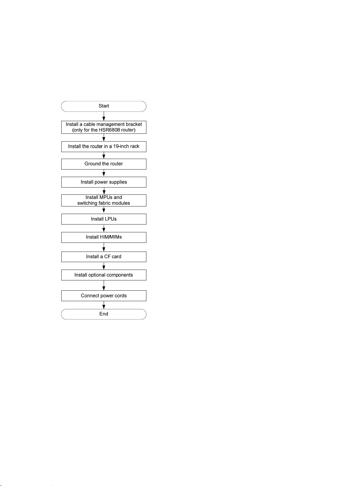
Installation flow
Figure 4 Installation flow
Installing a cable management bracket
The cable management brackets of the HSR6802 and HSR6804 are provided with mounting
brackets.
You need to install a cable management bracket for an HSR6808 router.
To install a cable management bracket:
1. Face the front of the router.
2. Align the screw holes on the cable management bracket with the screw holes on the front panel
of chassis, and use a Phillips screwdriver to fasten the screws.
9
Page 16
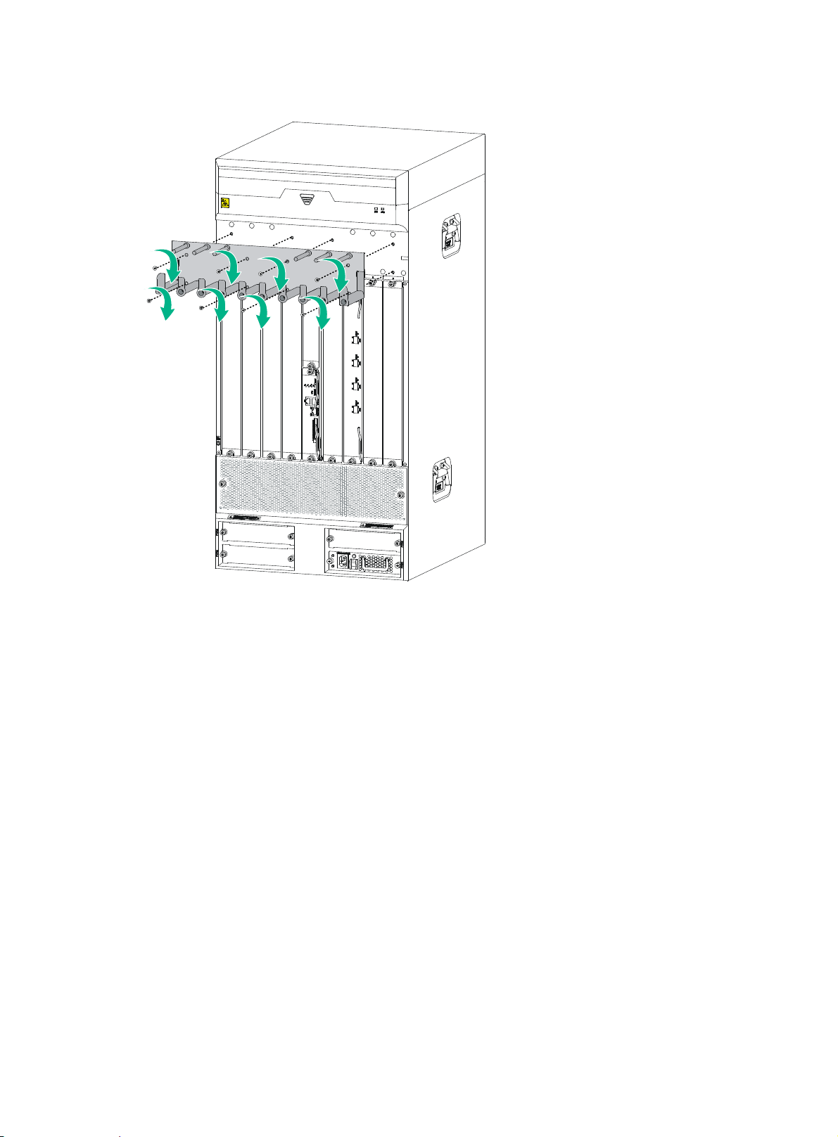
Figure 5 Installing a cable management bracket
Installing the router in a 19-inch rack
The procedures for installing an HSR6800 router in a rack are similar. This section uses an HSR6802
router as an example.
To install the router in a rack, you need mounting brackets and a rack shelf.
Installing cage nuts to the rack
1. Locate the installation position for the router and then install a rack shelf to the rack.
2. As shown in Figure 6, alig
mark the installation positions of cage nuts on the front rack posts.
n the bottom of the front mounting bracket with the rack shelf and
10
Page 17
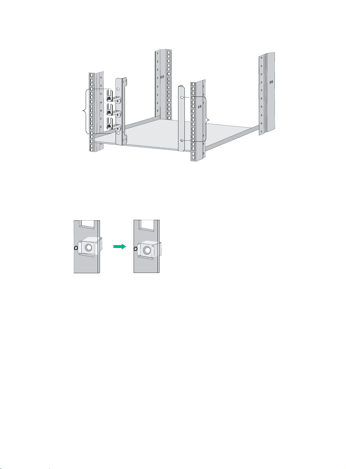
Figure 6 Marking the positions of cage nuts
5RU
5RU
3. Insert one edge of a cage nut into the hole.
4. Use a flat-blade screwdriver to compress the other edge of the cage nut, and then push the
cage nut fully into the hole.
5. Repeat steps 3 and 4 to install other cage nuts to all the marked positions on the rack post.
Figure 7 Installing a cage nut
Attaching the mounting brackets to the router
If you have ordered an air filter, install it to the router before you install the mounting brackets. For the
installation procedure, see "Installing an air filter."
Before you
the router.
To attach the front mounting brackets to the router, align the screw holes on the mounting brackets
with the screw holes on the left and right sides of the chassis, and then use a Phillips screwdriver to
fasten the screws.
install the router in a rack, install the front mounting brackets to the left and right sides of
11
Page 18
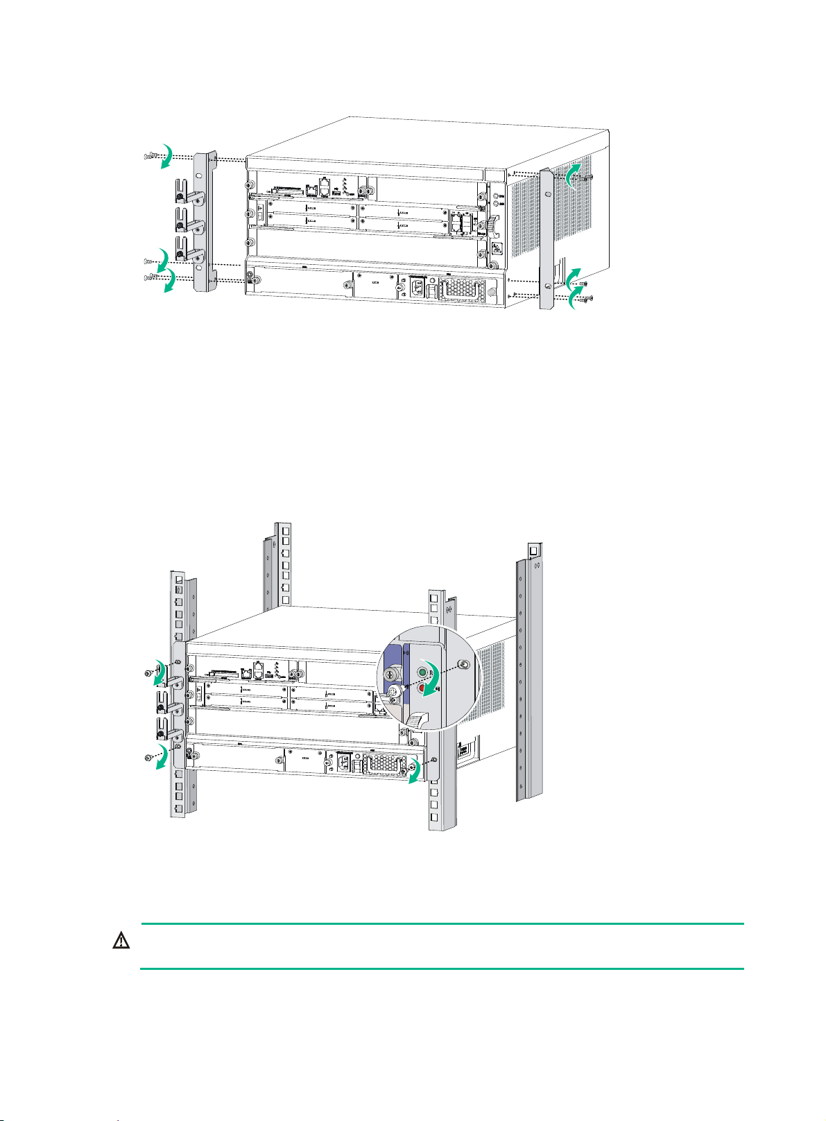
Figure 8 Attaching the front mounting brackets to the two sides of the router
Installing the router in a 19-inch rack
1. Put the router on the rack shelf.
2. Slide the router into the rack so the screw holes on the mounting brackets are aligned with holes
that are installed with cage nuts on the rack posts.
3. Use M6 screws to attach the mounting brackets to the rack posts. Make sure the rack shelf is
even and stable.
Figure 9 Installing the router in a rack
Grounding the router
WARNING!
Correctly connecting the router grounding cable is crucial to lightning protection and EMI protection.
To connect the grounding cable:
1. Remove the two grounding screws from the rear panel of the chassis.
12
Page 19
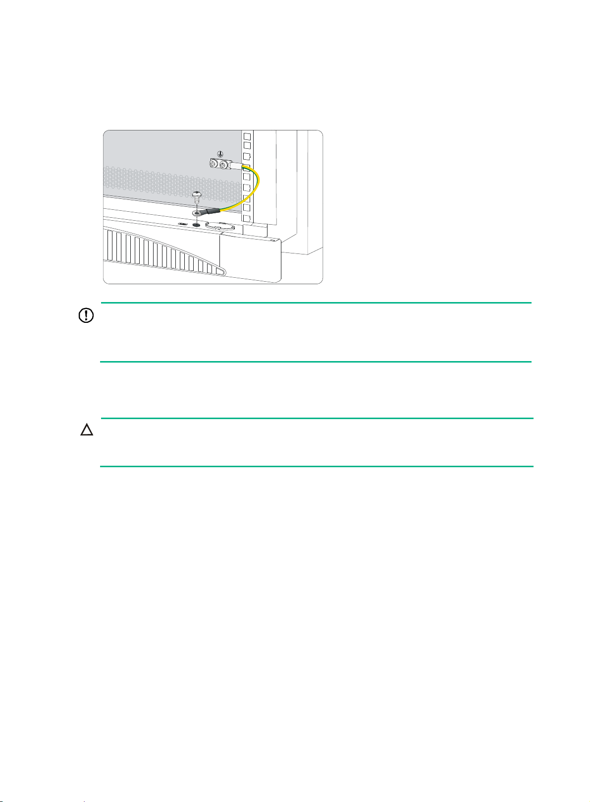
2. Attach the grounding screw to the ring terminal of the grounding cable.
3. Use a Phillips screwdriver to fasten the grounding screw into the grounding screw hole.
4. Connect the other end of the grounding cable to the grounding strip of the rack.
Figure 10 Connecting the grounding cable to the grounding hole of router
IMPORTANT:
The resistance reading should be smaller than 5 ohms between the chassis and the ground.
•
• To guarantee the grounding effect, use the grounding cable provided with the router to connect to the
grounding strip in the equipment room as long as possible.
Installing a power supply
CAUTION:
Do not install AC and DC power supplies on the same router.
•
• Power supplies on a router must be the same model.
Each of an HSR6802 and an HSR6804 router provides two power supply slots. An HSR6808 router
provides four power supply slots. Slots except the Slot 1 (PWR1) are provided with filler panels. The
routers support both AC (PSR650-A and PSR1200-A) and DC (PSR650-D and PSR1200-D) power
supplies
Before you install the power supply, make sure the power switch is off and the grounding cable is
reliably grounded.
The procedures for installing power supplies are the same. This section uses a PSR650-A as an
example.
To install a power supply:
1. Face the front of the router and locate the slot to be used.
2. Loosen the captive screws with a Phillips screwdriver to remove the filler panel from the slot.
Keep the removed filler panel for future use.
Skip this step if you install the power supply to the PWR1 slot.
3. Holding the handle of the power supply with one hand and supporting the bottom of the power
supply with the other hand, insert the power supply slowly along the slide rails until it makes
close contact with the backplane.
4. Use a Phillips screwdriver to fasten the captive screws on the two sides of the power supply.
For more information about the power supply LED description, see "Power supply LEDs."
13
Page 20
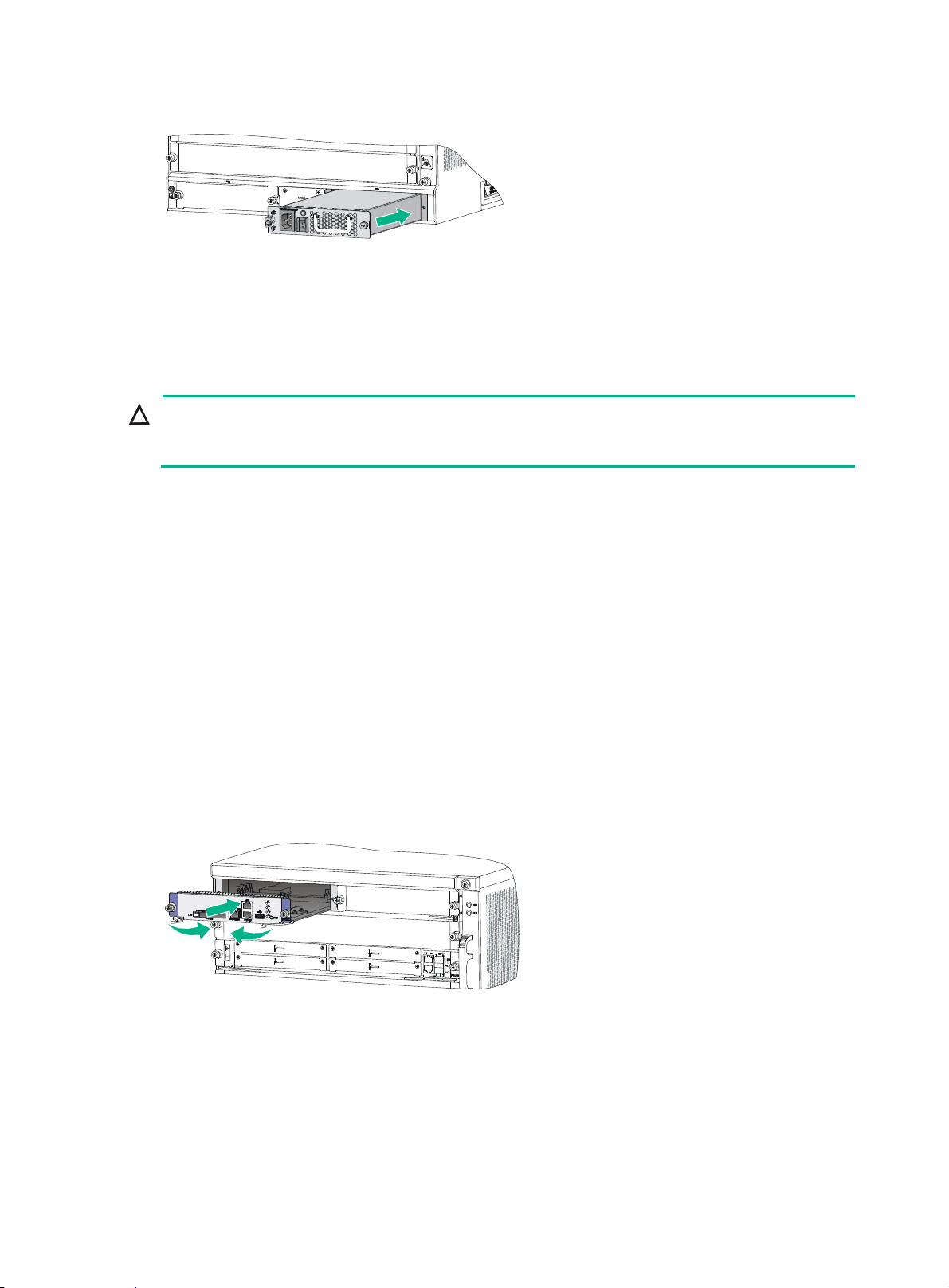
Figure 11 Installing a power supply
Installing an MPU and a switching fabric module
Installing an MPU
CAUTION:
The RUN LED flashes fast when the MPU is starting up. Do not install or remove the MPU during
this period to avoid hardware damage.
Before the installation, make sure the ejector levers of the MPU are outwards.
Slot 4 on the HSR6808 does not have a filler panel.
The installation procedures for the RSE-X2 and RSE-X3 MPUs are the same. The following example
uses the RSE-X2.
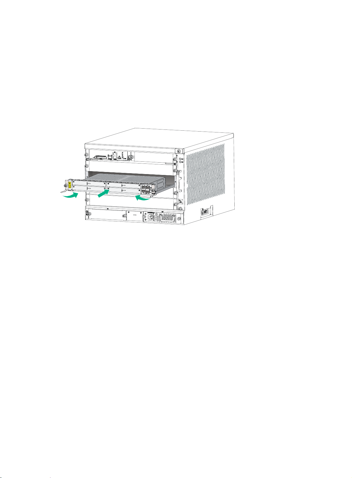
To install an MPU:
1. Face the front of the router and locate the slot to be used.
2. Loosen the captive screws with a Phillips screwdriver to remove the filler panel from the slot.
Keep the removed filler panel for future use.
Skip this step if you install the MPU to slot 4 of an HSR6808 router.
3. Insert the MPU slowly along the slide rails until it makes close contact with the backplane, and
then push the ejector levers inward to lock the MPU in position.
4. Use a Phillips screwdriver to fasten the captive screws on the two sides of the MPU.
For the MPU LED description, see "MPU and switching fabric module LEDs."
Figure 12 Installing an MPU
Installing an SFE-X1 switching fabric module
On the HSR6808, slot 6 must have an SFE-X1 switching fabric module installed.
Before the installation, make sure the ejector levers of the SFE-X1 are outwards.
To install an SFE-X1:
1. Face the front of the router and locate the slot.
14
Page 21
r
2. Loosen the captive screws with a Phillips screwdriver to remove the filler panel from the slot.
Keep the removed filler panel for future use.
3. Insert the SFE-X1 slowly along the slide rails until positioning pins on the backplane are seated
in the positioning holes, and then push the ejector levers inward to lock the SFE-X1 in position.
4. Use a Phillips screwdriver to fasten the captive screws on the two sides of the SFE-X1.
For the SFE-X1 LED description, see "MPU and switching fabric module LEDs."
Figure 13
Installing an SFE-X1
Installing an LPU
CAUTION:
The RUN LED flashes fast when the FIP is starting up. To avoid hardware damage, do not install o
remove a HIM/MIM during this period.
Slot 3 of the HSR6802/HSR6804 and Slot 7 of the HSR6808 are not provided with filler panels.
Before the installation, make sure the ejector levers of the LPU are outwards.
The procedures for installing LPUs are similar. This section uses a FIP-210 as an example.
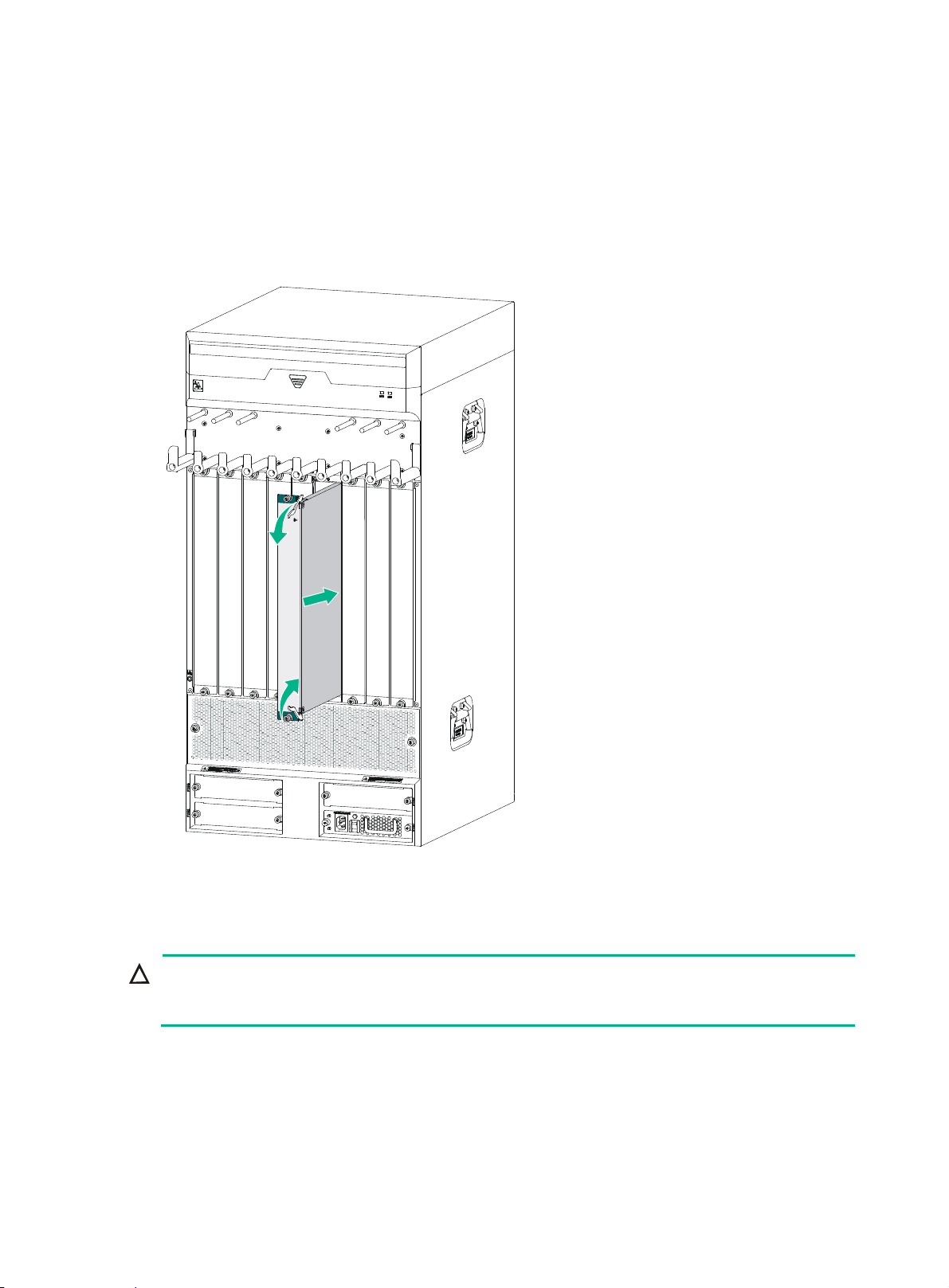
To install a FIP-210:
1. Face the front of the router and locate the slot to be used.
15
Page 22
2. Loosen the captive screws with a Phillips screwdriver to remove the filler panel from the slot.
Keep the removed filler panel for future use.
Skip this step if you install the FIP-210 to Slot 3 of the HSR6802/HSR6804, or Slot 7 of the
HSR6808.
3. Gently push the FIP-210 into the slot along the slide rails until positioning pins on the backplane
are seated in the positioning holes, and then push the ejector levers inward to lock the FIP-210
in position.
4. Use a Phillips screwdriver to fasten the captive screws on the two sides of the FIP-210.
For more information about the FIP LED description, see "FIP LEDs."
Figure 14
Inserting a FIP
Installing a HIM
Before the installation, make sure the ejector levers of the HIM are outwards.
The procedures for installing HIMs are similar. This example installs a HIM to a FIP-210.
To install a HIM:
1. Face the front of the router and locate the slot to install the HIM on the FIP-210.
A HIM occupies two slots of the FIP.
2. Loosen the captive screws with a Phillips screwdriver to remove the filler panel.
Keep the removed filler panel for future use.
3. Push the HIM slowly along the slide rails into the slot, and then pull the levers inward to lock the
HIM in position.
4. Use a Phillips screwdriver to fasten the captive screws on the HIM.
16
Page 23

Figure 15 Installing a HIM
Installing a MIM
The procedures for installing MIMs are similar. This example installs a MIM to a FIP-210.
To install a MIM:
1. Face the front of the router and locate the slot to install the MIM on the FIP-210.
The MIM should be installed in the lower slot on the FIP-210.
2. Loosen the captive screws with a Phillips screwdriver to remove the filler panel from the slot.
Keep the removed filler panel for future use.
3. Holding the handle of the MIM with one hand, push the MIM slowly along the slide rails into the
slot until the MIM is fully seated.
4. Use a flat-blade screwdriver to fasten the captive screws on the MIM.
Figure 16 Pushing the MIM into the slot
Installing a CF card
1. Push the CF card eject button all the way into the slot, and make sure the button does not
project from the panel.
17
Page 24
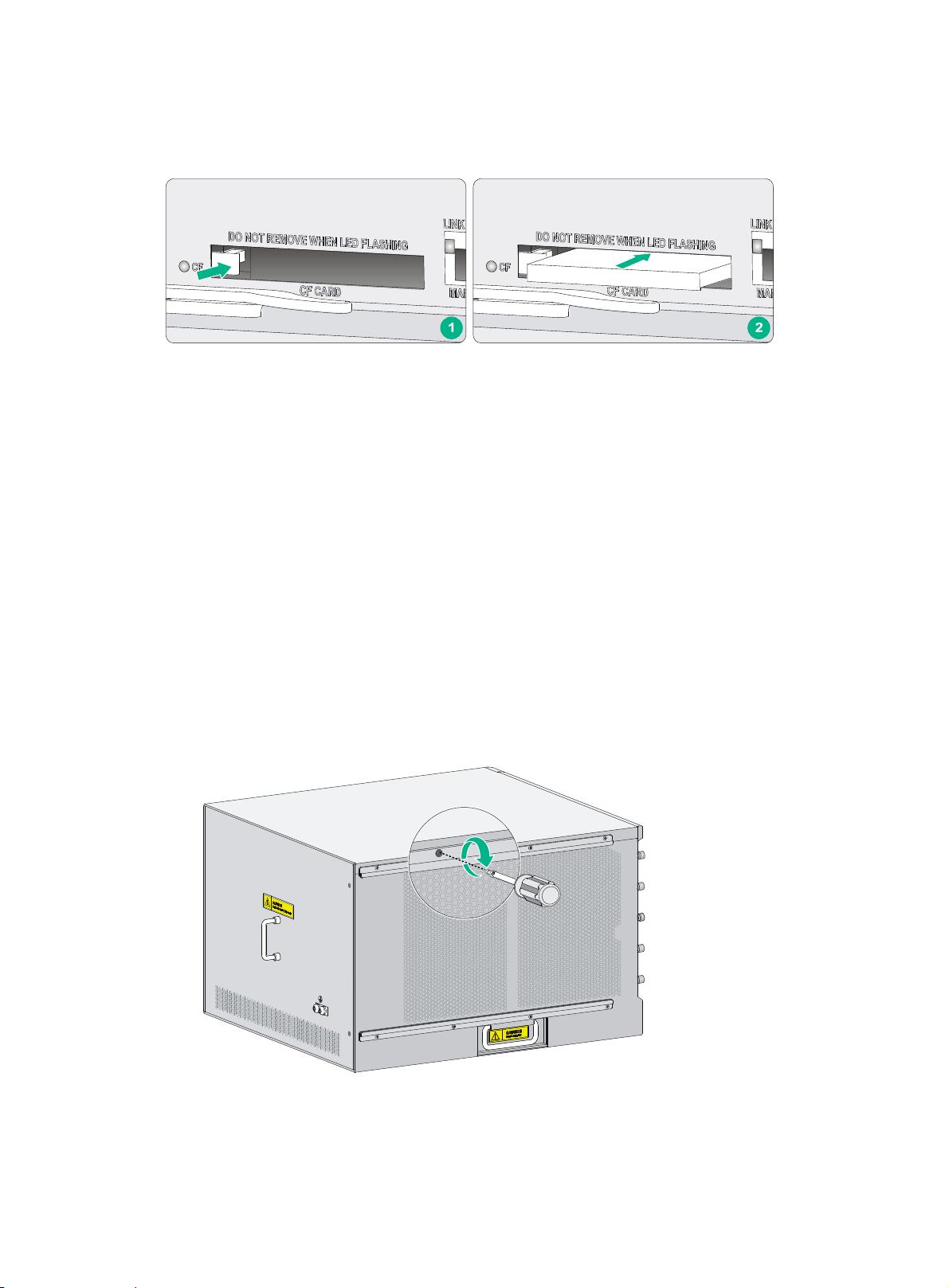
2. Insert the CF card into the slot following the direction shown in Figure 17, and make sure it does
not project from the slot.
Figure 17 Inserting the CF card into the slot
Installing optional components
Optional components (including the air filter and lightning protectors) are not provided with the router.
Purchase them if necessary.
Installing an air filter
Installing an air filter on an HSR6802/HSR6804
The methods for installing air filters on the HSR6802 and HSR6804 are the same. This section uses
an HSR6804 as an example.
To install an air filter:
1. Face the left side (side of the inlet vents) of the router.
2. Install the upper and lower slide rails on the chassis as shown in Figure 18.
3. Use a Phillips screwdriver to fasten the fasteni
Figure 18 Installing the upper and lower slide rails
ng screws on the upper and lower slide rails.
4. Push the air filter along the slide rails from the rear side of the chassis to the front.
18
Page 25
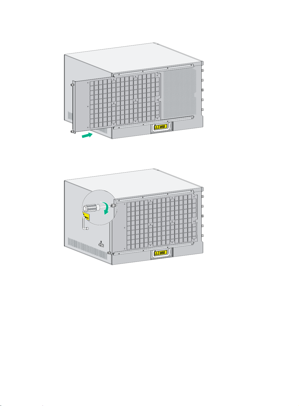
Figure 19 Inserting the air filter to the slide rail
5. Use a Phillips screwdriver to fasten the captive screws on the rear side of the air filter.
Figure 20 Fastening the captive screws
Installing an air filter on an HSR6808
1. Face the front of the router.
2. Align the positioning pins on the air filter with the screw holes on the inlet vent area, and use a
Phillips screwdriver to fasten the screws on the air filter.
19
Page 26

Figure 21 Installing an air filter on an HSR6808
Installing a lightning protector for a network port
Read the instructions for the lightning protector carefully before you install it.
The lightning protector for a network port is only applicable to a copper Ethernet port.
If part of the network cable of a copper Ethernet port must be routed outdoors, connect a lightning
protector to the cable before you plug the cable into the port.
You can install the following port lightning protectors to the router:
Type
10 Mbps/100 Mbps
port lightning
protector
1000 Mbps port
lightning protector
Installation procedure
1. Use a double-faced adhesive tape to stick the lightning protector onto the router chassis, and
make sure it is as close to the grounding screw of the router as possible.
2. Measure the distance between the protector and the grounding screw of the router, cut the
ground wire of the protector as appropriate, and securely tighten the ground wire to the
grounding screw of the router.
3. Use the multimeter to measure whether the ground wire of the protector contacts well with the
grounding screw of chassis.
4. Insert the outdoor network cable into the protector's IN end, and the cable connected to the
router into the OUT end, and examine the indicators on the lightning protector to verify that the
connection is correct.
5. Use nylon ties to bundle the cables neatly.
Port
description
Single port 2.5 KA
Single port 3 KA
Max. discharge current
(8/20μs waveform)
Output voltage
• Core-core ≤ 15 V
• Core-ground ≤ 300 V
• Core-core ≤ 15 V
• Core-ground ≤ 350 V
20
Page 27

Figure 22 Installing a lightning protector for a network port
(1) Grounding cable (2) Lightning protector
Installation precautions
The performance of the port lightning protector might be affected in the following cases:
• The port lightning protector is installed in reverse direction. Connect the IN end to the outdoor
network cable and the OUT end to the network port on the router.
• The port lightning protector is not reliably grounded. After the connection, use the multimeter to
confirm that the ground wire for the protector is as short as possible to ensure its good contact
with the grounding screw of the router.
• The installed port lighting protectors are not sufficient. If the router has more than one network
port connected with other devices through cables outdoor, install a lightning protector for each
network port.
Connecting the AC power supply to a power strip with lightning protection
CAUTION:
Make sure the PE terminal of the power socket has been securely grounded.
If part of the AC power line is routed outdoors, use a power strip with lightning protection to connect
the AC power cord of the router to the AC power line to protect the router from being damaged by
lightning strikes.
You can attach the power strip to the rack, workbench, or wall of equipment room.
After you connect the AC power cord from the router to a socket on the power strip, verify that the
green RUN LED on the strip is on and the red LED is off.
21
Page 28

If the red LED is on, use a multimeter to check the polarity of the wires in the power socket for wrong
connections. If the zero wire (left) and the live wire (right) are correctly connected, check for missing
grounding connection.
Figure 23 Power strip with lightning protection
L
N
(1) Operating LED (green)
(2) Grounding/pole detection LED (red)
(3) Power switch
(4) IEC standard socket
(5) Overload automatic protector
(6) Multifunctional socket It is used to connect the power supply of the router.
Installing a surge protector
NNN
LL
L
On means the circuit is operating correctly. Off means the circuit
is damaged.
On indicates a wrong wire connection. (The wire is not grounded
or the live line and null line are reversely connected.) In this case,
you need to check the power supply line.
It is used to connect to the power supply in the equipment room
through a power cord.
The protector automatically opens the electric circuit when the
current exceeds the threshold and closes the electric circuit when
the current drops below the threshold.
CAUTION:
Ground the surge protector as near as possible. The grounding resistance must be less than 4
ohms. The grounding resistance must be less than 1 ohm if there are special grounding
requirements.
Read the instructions carefully before installing the surge protector.
Generally, you need to connect a surge protector before connecting a signal cable to the router. This
can protect electronic devices against surge over-voltage resulting from lightning strokes and other
interferences, and minimize impact on the router.
The surge protector is serially connected to a signal cable, so the surge protector must satisfy the
requirements of network performance indexes such as data transmission bandwidth, as well as the
lightning protection performance requirement. Before installing a surge protector, consider such
performance indexes of the surge protector as lightning protection, bandwidth, transmission loss,
and port type.
22
Page 29

The router supports the following types of surge protectors:
• Surge protector—Maximum discharge current 2.5KA/protection voltage 25V--SMB-75J/
SMB-75J-1W-10Mbps
• Surge protector—Maximum discharge current 2.5KA/protection voltage 25V-BNC-75K/
BNC-75K-10Mbps
• Surge protector (U port)—Maximum discharge current 3KA/common-mode 400V/differential
mode 170V-RJ11
To install a surge protector:
1. Use a double-faced adhesive tape to stick the surge protector onto the router chassis, and
make sure it is as close to the grounding screw of the router as possible.
2. Measure the distance between the protector and the grounding screw of the router, cut the
ground wire of the protector as appropriate, and securely tighten the ground wire to the
grounding screw of the router.
3. Use the multimeter to measure whether the ground wire of the protector contacts well with the
grounding screw of chassis.
4. Insert the outdoor network cable into the protector's IN end, and the cable connected to the
router into the OUT end, and look at the indicators on the surge protector to verify that the
connection is correct.
5. Use nylon ties to bundle the cables neatly.
Figure 24 Installing a surge protector
(1) Grounding cable (2) Surge protector
The performance of the surge protector might be affected in the following cases:
• The surge protector is installed in reverse direction. Connect the IN end to the outdoor network
cable and the OUT end to the network port on the router.
• The surge protector is not reliably grounded. After the connection, use the multimeter to confirm
that the ground wire for the protector is as short as possible to ensure its good contact with the
grounding screw of the router.
23
Page 30

• The installed surge protectors are not sufficient. If the router has more than one cable
connected with other devices through cables outdoor, install a surge protector for each cable.
Connecting the power cord
Connecting an AC power cord
1. Make sure the router is reliably grounded, and the power switch on the router is in the OFF
position.
2. Connect one end of the AC power cord to the AC receptacle on the router, and the other end to
the AC power source.
3. Use cable ties to secure the power cord to the rack post.
Figure 25 Connecting an AC power cord to the router
Connecting DC power cords
Connecting power cords for the PSR650-D
WARNING!
To avoid connection mistakes, identify the label on the DC power cord.
CAUTION:
The power cord color code scheme in Figure 26 is for
country or region might use a different color scheme. When you connect a power cord, always
identify the polarity symbol on its wires.
To connect DC power cords:
1. Switch off the power supply.
2. Remove the protection cover of the DC power supply, and use a Phillips screwdriver to remove
the screws from the DC-input terminal block.
3. Connect the wire marked with the negative polarity symbol (– or L–) to the negative terminal (–)
on the power supply.
4. Connect the wire marked with the positive polarity symbol (+ or M/N) to the positive (+) terminal
on the power supply.
illustration only. The cable delivered for your
24
Page 31

r
5. Put the protection cover on the wiring terminals.
6. Connect the other ends of the wires to the DC power source wiring terminals, with the negative
wire (– or L–) to the negative terminal (–) and the positive wire (+ or M/N) to the positive terminal
(+).
Figure 26 Connecting DC power cords
Connecting power cords for the PSR1200-D
CAUTION:
The power cord color code scheme in this section is for illustration only. The cable delivered for you
country or region might use a different color scheme. When you connect a power cord, always
identify the polarity symbol on its wires.
To connect DC power cords:
1. Use a Phillips screwdriver to loosen the captive screw that secure the terminal block to the
power supply. Remove the terminal block.
Figure 27 Removing the terminal block
2. Insert one end of the wire marked with “–” into the terminal marked with “–”, and fasten the
screw to fix the cord.
25
Page 32

3. Insert one end of the wire marked with “+” into the terminal marked with “+”, and fasten the
screw to fix the cord.
Figure 28 Attaching the wires to the terminal block
4. Correctly orient the terminal block and insert it into the power supply, and fasten the captive
screws with a Phillips screwdriver.
Figure 29 Installing the terminal block on the power supply
5. Connect the other ends of the wires to the DC power source wiring terminals, with the negative
wire (– or L–) to the negative terminal block (–) and the positive wire (+ or M/N) to the positive
terminal block (+).
6. Use cable ties to secure the power cords to the rack post.
26
Page 33

Connecting interface cables
Connecting the AUX cable
Overview
An AUX cable has a crimped RJ-45 connector at one end for connecting to the AUX port of the router,
and D9 male connectors at the other end for connecting to the serial port of the modem.
Figure 30 AUX cable
Connecting the AUX cable
1. Plug the D9 male connector at one end of the AUX cable into the serial port on the modem.
2. Plug the RJ-45 connector of the AUX cable into the AUX port on the router.
Figure 31 Connecting the AUX port to a modem
27
Page 34

Connecting an Ethernet cable
Overview
10/100 Mbps Ethernet uses category-5 twisted pair cables, while 1000 Mbps Ethernet uses
category-5 enhanced or category-6 twisted pair cables. Twisted pair cables include straight-through
cables and crossover cables.
Category-5 cables provide a transmission frequency of 100 MHz for voice and data transmission;
they are mainly used in 100Base-T and 10Base-T networks. Category-5 cables are common
Ethernet cables, which can also be used to transmit 1000 Mbps Ethernet data.
Category-5 enhanced cables feature low attenuation and crosstalk, providing higher attenuation to
crosstalk ratio (ACR), less delay error and higher performance than category-5 cables. Category-5
enhanced cables are mainly used in 1000 Mbps Ethernet networks.
Category-6 cables provide a transmission frequency of 1 MHz to 250 MHz, and improve the
performance on crosstalk and return loss. A fine better return loss performance is extremely
important for new-generation full-duplex high-speed networks. Category-6 cables have sufficient
power sum ACR (PS-ACR) when working at 200 MHz. They provide a bandwidth two times than that
of category-5 enhanced cables, thus featuring a higher transmission performance. Therefore,
category-6 cables are suitable for applications requiring a transmission speed of more than 1 Gbps.
The 10/100 Mbps Ethernet uses two pairs of cables, orange/white, orange, green/white and green
cables, to transmit and receive data, while the 1000 Mbps Ethernet uses four pairs of cables to
transmit and receive data.
An Ethernet twisted pair cable connects network devices through the RJ-45 connectors at the two
ends. Figure 32 sh
Figure 32 RJ-45 connector pinout
PIN #8
PIN #1
EIA/TIA cabling specifications define two standards, 568A and 568B, for cable pinouts.
• Standard 568A—Pin 1: white/green stripe, pin 2: green steady, pin 3: white/orange stripe, pin 4:
blue steady, pin 5: white/blue stripe, pin 6: orange steady, pin 7: white/brown stripe, pin 8: brown
steady.
• Standard 568B—Pin 1: white/orange stripe, pin 2: orange steady, pin 3: white/green stripe, pin
4: blue steady, pin 5: white/blue stripe, pin 6: green steady, pin 7: white/brown stripe, pin 8:
brown steady.
Ethernet twisted pair cables can be classified into straight-through and crossover cables based on
their pinouts.
ows the pinouts of an RJ-45 connector.
For the pinouts of the twisted pair cables, see the following tables. (A and B represent the two ends of
a cable, respectively.)
28
Page 35

Table 8 Straight-through cable pinouts
Pinout No. A B
1 Orange/white Orange/white
2 Orange Orange
3 Green/white Green/white
4 Blue Blue
5 Blue/white Blue/white
6 Green Green
7 Brown/white Brown/white
8 Brown Brown
Table 9 Crossover cable pinouts
Pinout No. A B
1 Orange/white Green/white
2 Orange Green
3 Green/white Orange/white
4 Blue Blue
5 Blue/white Blue/white
6 Green Orange
7 Brown/white Brown/white
8 Brown Brown
NOTE:
To avoid affecting communication quality, strictly follow the pinouts in the above tables when
identifying or making the two types of Ethernet cables.
Making an Ethernet cable
1. Cut the cable to a required length with the crimping pliers.
2. Strip off an appropriate length of the cable sheath. The length is typically that of the RJ-45
connector.
3. Untwist the pairs so that they can lay flat, and arrange the colored wires based on the wiring
specifications.
4. Cut the top of the wires even with one another. Insert the wires into the RJ-45 end and make
sure the wires extend to the front of the RJ-45 end and make good contact with the metal
contacts in the RJ-45 end and in the correct order.
5. Crimp the RJ-45 connector with the crimping pliers until you hear a click.
6. Use a cable tester to verify the correct connectivity of the cable.
Connecting an Ethernet cable
1. Plug one end of an Ethernet twisted pair cable into the copper Ethernet port (RJ-45 port) or the
management Ethernet port to be connected on the router and the other end of the cable into the
29
Page 36

Ethernet port of the peer device. The 10/100/1000Base-T copper ports of the router support
MDI/MDI-X auto-sensing. They are connected to the network through category-5 or above
twisted pairs that are equipped with RJ-45 connectors.
2. Examine the status LED of the Ethernet ports. For more information about the LED status, see
"Appendix B LEDs."
Connecting a fiber cable
Transceiver module overview
When you use a fiber port, you need an SFP, XFP, SFP+, or QSFP+ transceiver module and a fiber
cable with an LC connector. For the compatibility between the cards and transceiver modules, see
HPE FlexNetwork 6600/HSR6600/HSR6800 Router Series Interface Module Guide.
Figure 33 SFP transceiver module
Figure 34 XFP transceiver module
Figure 35 SFP+ transceiver module
30
Page 37

Fiber cable overview
CAUTION:
Never exert a fierce force when you insert or remove a fiber connector.
•
• Never pull, press, or extrude the fiber fiercely.
Optical fibers can be classified into single-mode optical fibers and multi-mode optical fibers. A
single-mode optical fiber carries only a single ray of light, and a multi-mode optical fiber carries
multiple modes of lights.
Table 10 Characteristics of single-mode and multi-mode optical fibers
Item Single-mode optical fiber Multi-mode optical fiber
Core Small core (10 micrometers or less)
Larger core than single-mode
optical fiber (50 micrometers, 62.5
micrometers or greater)
Dispersion Less dispersion
Light source and
transmission distance
Users lasers as the light source often
within campus backbones for distance
of several thousand meters
Allows greater dispersion and
therefore, signal loss exists
Uses LEDs as the light source
often within LANs or distances of
a couple hundred meters within a
campus network
Table 11 lists the allowed maximum tensile load and crush load for the fiber.
Table 11 Allowed maximum tensile force and crush load
Period of force Tensile load (N) Crush load (N/mm)
Short period 150 500
Long term 80 100
Fiber connectors are indispensable passive components in an optical fiber communication system.
They allow the removable connection between optical channels, which makes the optical system
debugging and maintenance more convenient. There are multiple types of fiber connectors. Figure
ows an LC connector. Fiber ports of the HPE HSR6800 routers support only LC connectors.
36 sh
31
Page 38

Figure 36 LC connector
(1) LC connector (2) Optical fiber
Connecting a fiber cable
WARNING!
Do not stare into any fiber port when you connect an optical fiber. The laser light emitted from the
optical fiber might hurt your eyes.
To connect a fiber cable:
1. Remove the dust plug from a fiber port of the router.
2. Remove the dust cover from the transceiver module, and plug the end without a pull latch into
the fiber port.
3. Remove the dust cover from the fiber connector.
4. Identify the Rx and Tx ports. Plug the LC connector at one end of one fiber cable into the Rx port
of the router and the LC connector at the other end into the Tx port of the peer device. Plug the
LC connector at one end of another fiber cable into the Tx port of the router and the LC
connector at the other end to the Rx port of the peer device.
32
Page 39

Figure 37 Connecting a fiber cable
1 2
5. Examine the LINK LED after connection.
{ If the LED is on, the optical fiber link is present.
{ If the LED is off, no link is present. This might be because the TX and Rx port of the optical
fiber are not connected correctly. In this case, connect the optical fiber again.
Connecting a T3 cable
Overview
As a best practice, install a special lightning protector at the input end of the T3 cables to protect
them against lightning strikes more efficiently when they are routed outdoors.
You can use a T3 interface cable to connect the MIM-1T3-V2 modules.
Figure 38 T3 cable
3 4
Connecting a T3 cable
1. Connect the SMB connector of a T3 cable to the Tx port on the interface module and the other
end to the Rx port on the device to be connected.
2. Connect the SMB connector of another T3 cable to the Rx port of interface module and the
other end to the Tx port on the device to be connected.
33
Page 40

Figure 39 Connecting a T3 cable
34
Page 41

Accessing the router
Login methods
The following logins methods are available for you to log in to the router:
• Logging in through the console port, which is the most common way to log in to a router and
also the prerequisite for configuring other login methods.
• Logging in through Telnet or SSH.
• Logging in through the AUX port.
Logging in through the console port
You can log in only through the console port the first time you log in to your router.
Before you log in to the router, prepare an 8-core shielded cable, with a crimped RJ-45 connector at
one end, and a DB-9 male connector at the other end, and a PC with the operating system Windows
95/98/NT/2000/XP/7. This section uses a PC with Windows XP as an example.
Setting up a configuration environment
CAUTION:
When you disconnect a PC from a powered-on router, disconnect the DB-9 connector of the
console cable from the PC after disconnecting the RJ-45 connector from the router.
To set up a configuration environment:
1. Plug the DB-9 female connector to the serial port of the configuration terminal.
2. Connect the RJ-45 connector to the console port of the router.
Figure 40 Connecting the console cable
35
Page 42

Setting terminal parameters
1. Select Start > All Programs > Accessories > Communications > HyperTerminal.
The Connection Description dialog box appears.
Figure 41 Connection description
2. Select the serial port to be used from the Connect using list, and click OK.
Figure 42 Setting the serial port used by the HyperTerminal connection
3. Set Bits per second to 9600, Data bits to 8, Parity to None, Stop bits to 1, and Flow control
to None, and click OK.
36
Page 43

Figure 43 Setting the serial port parameters
4. Select File > Properties in the HyperTerminal window.
Figure 44 HyperTerminal window
5. On the Settings tab, set the emulation to VT100 and click OK.
37
Page 44

Figure 45 Setting terminal emulation in test Properties dialog box
Powering on the router
Verifying before power-on
Before powering on the router, verify the following items:
• The power supplies and fan trays are correctly installed.
• The power cord and grounding cable are correctly connected.
• The power source voltage meets the requirement of the router.
• The console cable is correctly connected, the terminal or PC used for configuration has started,
and the configuration parameters have been set.
• If a CF card is used, verify that the CF card is in position.
• Make sure the installed LPUs and HIMs/MIMs are in position.
Powering on the router
• Turn on the switch of the power supply system for the router.
• Turn on the switch of the AC or DC power supplies.
Displaying boot information
Power on the router, and you can see the following information:
System is starting...
Press Ctrl+D to access BASIC-BOOTWARE MENU
38
Page 45

Press Ctrl+T to start memory test
Booting Normal Extended BootWare
The Extended BootWare is self-decompressing.......................Done.
****************************************************************************
* *
* HPE Router BootWare, Version 2.04 *
* *
****************************************************************************
Copyright (c) 2010-2017 Hewlett Packard Enterprise Development LP
Compiled Date : Nov 6 2016
CPU Type : P2020
CPU L1 Cache : 32KB
CPU Clock Speed : 1000MHz
Memory Type : DDR3 SDRAM
Memory Size : 4096MB
Memory Speed : 667MHz
Flash Size : 8MB
cfa0 Size : 999MB
NVRAM Size : 128KB
BASIC CPLD Version : 2.0
EXTENDED CPLD Version: 2.0
PCB Version : Ver.B
BootWare Validating...
Press Ctrl+B to access EXTENDED-BOOTWARE MENU...
Loading the main image files...
---- More ----
Press Enter, and the following prompt appears:
<HPE>
You can now configure the router.
Logging in to the router through Telnet/SSH
1. After powering on the router, log in to the router through the console port.
2. Use the telnet server enable command and the ssh server enable command to enable the
Telnet and SSH function on the router, respectively, and use the user privilege level
command to set the user privilege level.
3. Connect the PC to the management Ethernet port or the copper Ethernet port on the router and
specify an IP address for the port.
4. Specify an IP address for the PC, making sure the PC and the port are in the same network
segment.
For more information about how to log in to the router through Telnet/SSH, see HPE FlexNetwork
HSR6800 Routers Configuration Guides.
39
Page 46

Logging in to the router through the AUX port
1. After powering on the router, connect the console cable to the console port.
To configure the AUX port:
Step Command
1. Enter system view.
2. Enter AUX user interface view.
3. Set the authentication mode.
4. Set the user privilege level.
system-view
user-interface aux 0
authentication-mode none
user privilege level 3
2. Plug the D-9 female connector to the serial port of the configuration terminal or PC.
3. Connect the RJ-45 connector to the AUX port of the router. Then you can log in to the router
through the AUX port.
For more information about how to log in to the router through an AUX port, see HPE FlexNetwork
HSR6800 Routers Fundamentals Configuration Guide.
Configuring basic settings
Step Command Remarks
1. Set the current time and date.
2. Enter system view.
3. Enter Ethernet interface view.
4. Specify an IP address for the
interface.
5. Return to system view.
6. Specify a static route.
7. Save the current
configuration to the startup
configuration file in the root
directory of the storage
media.
8. Verify the running
configuration.
clock datetime
system-view
interface
interface-number
ip address
mask } [
quit
ip route-static
mask-length } { next-hop-address |
interface-type interface-number
[ next-hop-address ] |
d-vpn-instance-name
next-hop-address }
track-entry-number [
preference-value ] [
[
save
[
display current-configuration
sub
description
safely
[
force
]
time date
interface-type
ip-address { mask-length |
]
dest-address { mask |
description-text ]
backup
] [
vpn-instance
track
preference
tag
tag-value ]
main
|
]
Optional.
Available in user view.
Available in user view.
N/A
By default, no IP address is
assigned to any interface.
Available in any view.
By default, the preference
of a static route is 60, tag is
0, and no description is
configured.
Available in any view.
Available in any view.
40
Page 47

Replacement procedures
The router uses modular design. All modules for the router are hot swappable.
Safety recommendations
• Always wear an ESD wrist strap or ESD gloves when you replace the modules.
• To hot swap an LPU or HIM/MIM, first use the remove command to stop the card from
operating.
• When you replace FRUs, such as MPUs, LPUs, memory modules, the CF card, and
HIMs/MIMs, follow these guidelines:
{ Ensure good alignment with the slot to avoid damage to the module during installation or
removal.
{ To prevent module panel deformation, make sure the captive screws are completely
loosened before removing a module.
{ Avoid touching any components on the PCB during observing or moving the module.
{ Put the removed module on an antistatic workbench with the PCB side facing upward or
place them in antistatic bags.
Replacing a power supply
The replacement procedures for an AC power supply and a DC power supply are the same. This
section uses an AC power supply as an example.
To replace a power supply:
1. Face the front of the router and locate the power supply to be removed.
2. Use a Phillips screwdriver to completely loosen the captive screws of the power supply.
3. Holding the handle of the power supply with one hand and supporting the bottom of the power
supply with the other hand, gently pull the power supply out of the slot along the slide rails.
Put the removed power supply on an antistatic workbench or into an antistatic bag.
Figure 46 Pulling the power supply out of the slot
4. Install a new power supply. For the installation procedure, see "Installing a ."
If you do not install a new power supply in the slot, install a filler panel.
Replacing an MPU and a switching fabric module
Prerequisites
• If the router is installed with only one MPU, make sure all power sources to the router are turned
off before replacing the MPU.
41
Page 48

• If the router is installed with two MPUs, make sure both MPUs operate correctly before
replacement.
{ As a best practice to replace the active MPU, execute the slave switchover command in the
system view of the active MPU to trigger an active and standby switchover. For more
information about the slave switchover command, see HPE FlexNetwork HSR6800 Route rs
High Availa bility Command Reference.
{ To replace the standby MPU, you can remove it immediately.
Replacing an MPU
The replacement procedures for the RSE-X2 and RSE-X3 MPUs are the same. The following
example uses an RSE-X2.
To replace an MPU:
1. Face the front of the router and locate the MPU to be removed.
2. Use a Phillips screwdriver to completely loosen the captive screws of the MPU.
3. Holding the ejector levers of the MPU with both hands, pull the ejector levers outward, and
gently pull the MPU out of the slot along the slide rails.
Figure 47 Pulling the RSE-X2 MPU out of the slot
4. Install a new MPU. For the installation procedure, see "Installing an MPU."
If you do not install a new MPU in the slot, install a filler panel.
Replacing an SFE-X1
1. Face the front of the router and locate the SFE-X1 to be removed.
2. Use a Phillips screwdriver to completely loosen the captive screws on the SFE-X1.
3. Holding the ejector levers of the SFE-X1 with both hands, pull the ejector levers outward, and
gently pull the SFE-X1 out of the slot along the slide rails.
42
Page 49

Figure 48 Pulling the SFE-X1 out of the slot (HSR6808)
4. Install a new SFE-X1. For the installation procedure, see "Installing an SFE-X1 switching fabric
module."
If you do not install a new SFE-X1 in the slot, install a filler panel.
Replacing an LPU
CAUTION:
To avoid hardware damage, do not replace the LPU when its RUN LED is fast flashing.
To replace an LPU, for example, FIP-210:
1. Face the front of the router and locate the FIP module to be removed.
2. Use a Phillips screwdriver to completely loosen the captive screws of the FIP module.
3. Holding the ejector levers of the FIP module with both hands, pull the ejector levers outward,
and gently pull the FIP module out of the slot along the slide rails.
43
Page 50

Figure 49 Pulling the FIP module out of the slot
4. Install a new FIP module. For the installation procedure, see "Installing an LPU."
If you do not install a new FIP module in the slot, install a filler panel.
Replacing a HIM
1. Face the front of the router and locate the HIM to be removed.
2. Use a Phillips screwdriver to completely loosen the captive screws of the HIM.
3. Holding the two ejector levers with both hands, pull the ejector levers outward, and gently pull
the HIM out of the slot along the slide rails.
Figure 50 Pulling the HIM out of the slot
4. Install a new HIM. For the installation procedure, see "Installing a HIM."
If you do not install a new HIM in the slot, install a filler panel.
Replacing a MIM
1. Face the front of the router and locate the MIM to be removed.
2. Use a flat-blade screwdriver to completely loosen the captive screws of the MIM.
3. Holding the handle of the MIM, gently pull the MIM out of slot along the slide rails.
44
Page 51

Figure 51 Pulling the MIM out of the slot
4. Install a new MIM. For the installation procedure, see "Installing a MIM."
If you do not install a new MIM in the slot, install a filler panel.
Replacing a CF card
CAUTION:
To avoid hardware damage, do not remove the CF card when the router is booting or the CF LED is
flashing.
To replace a CF card:
1. Press the CF card eject button of the CF card reader so that the eject button projects from the
panel.
2. Press the eject button again to eject the CF card part-way out of the CF card reader, and then
pull the CF card out of the CF card reader.
Figure 52 Removing a CF card
3. Install a new CF card. For the installation procedure, see "Installing a CF card."
Replacing a transceiver module
1. Pressing the tab of the LC connector, pull out the LC connector from the transceiver module.
Put on the dust cap for the LC connector.
2. Pivot the clasp of the transceiver module down to the horizontal position.
3. Hold the clasp to gently pull the transceiver module out.
45
Page 52

Put the dust plug on the removed module, and put the removed module into its original shipping
materials.
4. Install a new transceiver module. For the installation procedure, see "Connecting a fiber cable."
If you do not install a new transceiver module in the interface, install a dust-proof plug in the
interface.
Figure 53 Removing a transceiver module
Replacing a fan tray
CAUTION:
Keep your hands away from the spinning fan blades when removing the fan tray.
•
• Do not keep the router working without a fan tray for more than two minutes because poor ventilation might
result in damage to the router.
Replacing a fan tray for an HSR6802/HSR6804 router
The methods for replacing fan trays for the HSR6802 and HSR6804 are the same. This section uses
an HSR6804 as an example.
To replace a fan tray:
1. Face the front of the router.
2. Use a Phillips screwdriver to completely loosen the captive screws of the fan tray to be
removed.
3. Holding the handle of the fan tray with one hand and supporting the bottom of the fan tray with
the other hand, gently pull the fan tray out of the slot along the slide rails.
46
Page 53

Figure 54 Pulling out the fan tray
4. Holding the handle of the fan tray with one hand and supporting the bottom of the fan tray with
the other hand, gently push the fan tray into the slot along the slide rails until it is completely
seated.
5. Use a Phillips screwdriver to fasten the captive screws on the fan tray.
Replacing a fan tray for an HSR6808 router
1. Face the front of the router.
2. Press the fan tray release button with the thumb, slightly pull the fan tray away from the chassis,
and slowly pull the fan tray out along the slide rails when fans stop spinning.
3. Holding the front part of the fan tray with one hand, pressing down the release button with the
thumb, and supporting the bottom of the fan tray with the other hand, push the fan tray into the
slot along the slide rails until the fan tray makes complete contact with the backplane.
Figure 55 Pulling out the fan tray
Replacing an air filter
IMPORTANT:
You can clean the air filter with water, but wait until it is completely dry before installing it again.
47
Page 54

Replacing an air filter for an HSR6802/HSR6804 router
1. Face the left side of the router.
2. Use a Phillips screwdriver to completely loosen the captive screws of the air filter.
Figure 56 Loosening the captive screws of the air filter
3. Gently pull the air filter out along the slide rails.
Figure 57 Pulling the air filter out along the slide rails
4. Install a new air filter. For the installation procedure, see "Installing an air filter on an
HSR6802/HSR6804."
Replacing an air filter for an HSR6808 router
1. Face the front of the router.
2. Use a Phillips screwdriver to completely loosen the captive screws of the air filter.
48
Page 55

Figure 58 Removing the air filter
3. Install a new air filter. For the installation procedure, see "Installing an air filter on an HSR6808."
Replacing a memory module
CAUTION:
For the router to operate correctly, use the memory modules provided by Hewlett Packard
Enterprise only.
The MPUs and LPUs are equipped with memory modules. Before you install or remove a memory
module, remove the MPU or LPU from the chassis first. For more information, see "Replacing an
MPU and a
switching fabric module" and "Replacing an LPU."
For the memory module specifications, see "Appendix A Chassis views and technical specifications."
Memory module structure
Figure 59 Memory module structure (DDR2)
1 2 3
(a) Front view
1 2 3
(b) Rear view
(1) Connector edge (2) Polarization notch
(3) Latch notch
49
Page 56

Figure 60 Memory module structure (DDR3)
(1) Connector edge (2) Polarization notch
(3) Latch notch
Replacing a memory module
The methods for replacing memory modules are similar. This example replaces a memory module
on an RSE-X2.
To replace a memory module:
1. Pull the release latches away from the memory module at both ends so that the memory
module is lifted from the memory module slot.
2. Holding the non-conductive edge, remove the memory module.
3. Align the polarization notch of the memory module with the key in the connector.
4. Insert the memory module into the slot.
5. Carefully and firmly press the memory module at both ends until you hear a click. This indicates
the memory module is seated in the memory module slot.
6. Verify that the release latches have firmly locked the memory module in position.
Figure 61 Replacing a memory module
50
Page 57

Hardware management and maintenance
The output depends on your router model and software version. For more information about the
commands used in this chapter, see HPE FlexNetwork HSR6800 Routers Command References.
Displaying the hardware information of the router
Displaying the version information of the router
Use the display version command to display software and hardware version information of the
router. The output includes the following information: the current software version and hardware
version, router operating time, type and operating time of each MPU and LPU.
<Sysname> display version
HPE Comware Software, Version 7.1.064, Release 7607
Copyright (c) 2010-2017 Hewlett Packard Enterprise Development LP
HPE HSR6802 uptime is 0 weeks, 0 days, 4 hours, 16 minutes
Last reboot reason : Power on
Boot image: cfa0:/HSR6800-CMW710-BOOT-R7607.bin
Boot image version: 7.1.064, Release 7607
Compiled Dec 09 2016 16:00:01
System image: cfa0:/HSR6800-CMW710-SYSTEM-R7607.bin
System image version: 7.1.064, Release 7607
Compiled Dec 09 2016 16:00:01
---- More ----
Displaying the running statistics for the router
For diagnosis or troubleshooting, you can use separate display commands to collect running status
data module by module, or use the display diagnostic-information command to bulk collect
running data for multiple modules. This command displays the output of the display clock, display
version, display device, and display current-configuration commands.
• Save the operating statistics for each module of the router.
<Sysname> display diagnostic-information
Save or display diagnostic information (Y=save, N=display)? [Y/N]:y
Please input the file name(*.diag)[cfa0:/default.diag]:aa.diag
Diagnostic information is outputting to cfa0:/aa.diag.
Please wait...
Recv slot 4 response packet.
Save successfully.
Execute the more aa.diag command in user view, and then press the Page Up and Page
Down keys to view the contents of the file aa.diag.
• Display the operating statistics for each module of the router.
<Sysname> display diagnostic-information
Save or display diagnostic information (Y=save, N=display)? [Y/N]:n
=================================================
51
Page 58

===============display clock===============
=================================================
08:54:16 UTC Fri 15/06/2012
===================================================
===============display version===============
===================================================
…
Displaying detailed information about a card
• Use the display device verbose command to display detailed information about all cards.
<Sysname>display device verbose
System-mode(Current/After Reboot): Normal/Normal
Slot No. Board type Status Primary SubSlots
-------------------------------------------------------------------- 0 N/A Absent N/A N/A
1 RSE-X2 Normal Master 0
2 N/A Absent N/A N/A
3 N/A Absent N/A N/A
4 FIP-110 Normal N/A 4
5 N/A Absent N/A N/A
Slot 4 : FIP-110(4 Subslots)
Subslot 1 : MIM-4GBE
Subslot 2 : MIM-4GBE
• Use the display device slot slot-number command to display detailed information about the
card in the specified slot.
<Sysname> display device slot 1
System-mode(Current/After Reboot): Normal/Normal
Slot 1 : RSE-X2
SubSlot No. Card Type Status Max Ports
------------------------------------------------------- 1 Fixed SubCard Normal 3
Table 12 Command output
Field Description
Slot No. Slot number of the card.
52
NONE
indicates that no card is present in the slot.
Card Type Card model. The value
Running status of the card:
• Absent—No card is present in the slot.
Status
• Fault—The card in the slot is booting, or the card has failed and cannot
boot correctly.
• Normal—The card in the slot is operating correctly.
Max Ports Maximum number of ports that the card supports.
Page 59

Displaying the electrical label data
Electrical label data is also called permanent configuration data or archive information, which
includes the card name, serial number, MAC address, and vendor name.
• Use the display device manuinfo command to display the electrical label data for the card in
each slot.
<Sysname> display device manuinfo
...
• Use the display device manuinfo slot slot-number command to display the electrical label
data for the card in the specified slot.
<Sysname> display device manuinfo slot 0
...
Table 13 Command output
Field Description
DEVICE_NAME Card type.
DEVICE_SERIAL_NUMBER Card serial number.
MAC address of the card:
MAC_ADDRESS
• An MPU has a MAC address.
• An LPU does not have a MAC address, and the field displays
NONE.
MANUFACTURING_DATE Manufacturing date of the card.
The operation is not supported
on the specified board or subslot
display device manuinfo
The
is virtualized through the MPU.
Displaying the CPU usage statistics
Use the display cpu-usage command to display the CPU usage statistics for all cards.
<Sysname> display cpu-usage
Slot 0 CPU usage:
2% in last 5 seconds
2% in last 1 minute
1% in last 5 minutes
Slot 5 CPU usage:
1% in last 5 seconds
1% in last 1 minute
1% in last 5 minutes
Table 14 Command output
Field Description
CPU usage of the card in slot 0.
Slot 0 CPU usage
If the card in the slot has multiple CPUs, "Slot 0 CPU usage" displays the usage of
the master CPU of the card in slot 0, and "Slot 0 CPU 1 CPU usage" displays the
usage of the auxiliary CPU of the card in slot 0.
command is not supported on a card that
1% in last 5 seconds
After a boot, the system calculates and records the average CPU usage rate
every five seconds.
This field displays the average CPU usage rate in the last five seconds.
53
Page 60

Field Description
After a boot, the system calculates and records the average CPU usage rate
1% in last 1 minute
1% in last 5 minutes
every one minute.
This field displays the average CPU usage rate in the last minute.
After a boot, the system calculates and records the average CPU usage rate
every five minutes.
This field displays the average CPU usage rate in the last five minutes.
Displaying the MPU memory usage
Use the display memory command to display the active MPU memory information.
<Sysname> display memory
System Total Memory(bytes): 4069505360
Total Used Memory(bytes): 277820968
Used Rate: 6%
Table 15 Command output
Field Description
System Total Memory(bytes) Physical memory size (in bytes) of the MPU.
Total Used Memory(bytes) Used memory size (in bytes) of the MPU.
Used Rate Memory usage of the MPU.
Displaying the CF card information
Use the display device cf-card command to display the CF card information.
<Sysname> display device cf-card
Slot No. Dev No. Status Size(M)
-----------------------------------------------
0 0 Normal 999
0 1 Absent N/A
Table 16 Command output
Field Description
Slot No. Slot number of the CF card.
Device number of the CF card:
Dev No.
Status:
• 0 for a built-in CF card.
• 1 for an external CF card.
Operating status of the CF card:
• Absent—No CF card is present in the slot.
• Fault—The CF card has failed.
• Normal—The CF card is operating correctly.
Size: Storage capacity of the CF card.
54
Page 61

Displaying the fan operating status
Use the display fan command to display the fan operating status.
<Sysname> display fan
Fan 1 State: Normal
Table 17 Command output
Field Description
Fan 1 Number of the fan.
Fan state:
State
• Normal—The fan is operating correctly.
• Absent—The fan is not in position.
• Fault—The fan has failed.
Displaying the power supply operating status
Use the display power command to display the power supply operating status.
<Sysname> display power
System Power Total : 650 watts
System Power Used : 275 watts
System Power Usable : 375 watts
Power No. Type Watts State ID
---------------------------------------------
1 N/A N/A Absent N/A
2 AC 650 Normal 0
Table 18 Command output
Field Description
System Power Total Total power provided by the power supplies.
System Power Used Power in use.
System Power Usable Power available for use.
Power No. Slot number of the power supply.
Power supply type:
Type
Watts Power provided by the power supply.
ID Power supply ID.
State
• AC—AC power supplies.
• DC—DC power supplies.
Power supply state:
• Normal—The power supply is operating correctly.
• Absent—The power supply is not in position.
• Fault—The power supply has failed.
55
Page 62

Displaying the alarming thresholds of a card
Use the display environment command to display the temperature information and alarming
thresholds of a card.
<Sysname> display environment
Temperature information (degree centigrade):
----------------------------------------------------------
SlotNo Temperature Lower limit Upper limit
1 38 -10 53
4 34 -10 53
Table 19 Command output
Field Description
SlotNo Slot number of the card.
Temperature Current temperature of the card.
Lower limit Low temperature threshold of the card.
Upper limit High temperature threshold of the card.
Port configuration and management
Configuring a combo interface
A combo interface is a logical interface that contains an SFP port of a transceiver module and an
RJ-45 Ethernet port. The two ports share one forwarding interface, so they cannot work
simultaneously. When you enable either port, the other port is automatically disabled. You can select
to activate a port as needed.
Use the display interface interface-type interface-number command to find out which port is an SFP
port and which port is an RJ-45 Ethernet port.
• If the output includes "Media type is optical fiber," it means that the port is an SFP port. For
example, the following output shows that GigabitEthernet 5/0/1 is an SFP port.
[Sysname] display interface GigabitEthernet 5/0/1
GigabitEthernet5/0/1 current state: DOWN
Line protocol current state: DOWN
Description: GigabitEthernet5/0/1 Interface
The Maximum Transmit Unit is 1500
Internet protocol processing : disabled
IP Packet Frame Type: PKTFMT_ETHNT_2, Hardware Address: 2222-2222-2122
IPv6 Packet Frame Type: PKTFMT_ETHNT_2, Hardware Address: 2222-2222-2122
Media type is optical fiber, loopback not set, promiscuous mode not set
…
• If the output includes "Media type is twisted pair," it means that the interface is an RJ-45
Ethernet port. For example, the following output shows that GigabitEthernet 5/0/0 is an RJ-45
Ethernet port.
[Sysname] display interface GigabitEthernet 5/0/0
GigabitEthernet5/0/0 current state: DOWN
Line protocol current state: DOWN
56
Page 63

Description: GigabitEthernet5/0/0 Interface
The Maximum Transmit Unit is 1500
Internet protocol processing : disabled
IP Packet Frame Type: PKTFMT_ETHNT_2, Hardware Address: 2222-2222-2122
IPv6 Packet Frame Type: PKTFMT_ETHNT_2, Hardware Address: 2222-2222-2122
Media type is twisted pair, loopback not set, promiscuous mode not set
…
To configure a combo interface:
Step Command Remarks
1. Enter system view.
2. Enter view of the SFP port
or RJ-45 port of the combo
interface.
3. Activate the RJ-45 Ethernet
port or SFP port.
system-view
interface
interface-number
combo enable
fiber }
interface-type
{
copper
N/A
N/A
|
By default, the fiber port is active.
Displaying and verifying transceiver modules
Table 20 Commonly used transceiver modules
Transceiver module
type
SFP (small form-factor
pluggable)
XFP (10-Gigabit small
form-factor pluggable)
SFP+ (enhanced small
form-factor pluggable)
Application scenarios
Generally used for 100M/1000M
Ethernet interfaces or POS
155M/622M/2.5G interfaces.
Generally used for 10G
interfaces.
Generally used for 10G
interfaces.
Displaying transceiver module information
To identify transceiver modules, you can use the following command to view the key parameters of
the transceiver modules, including transceiver module type, connector type, central wavelength of
the laser sent, transmission distance, and vendor name or name of the vendor who customizes the
transceiver modules.
To display transceiver module information:
Task Command Remarks
Display key parameters of the
transceiver module in a specified
interface.
display transceiver interface
[ interface-type interface-number ]
Whether can
be an optical
transceiver
Yes. Yes.
Yes. No.
Yes. No.
Available for all transceiver
modules.
Whether can be
an copper
transceiver
Verifying transceiver modules
The system outputs alarm information for you to locate and troubleshoot faults of transceiver
modules. For the Hewlett Packard Enterprise anti-counterfeit transceiver modules, the system can
also monitor the key parameters, such as temperature, voltage, laser bias current, TX power, and RX
power. When these parameters are abnormal, you can take corresponding measures to prevent
transceiver module faults.
57
Page 64

To display the alarming information or fault detection parameters of a transceiver module:
Task Command Remarks
Display the current alarm
information of the transceiver
module in a specified interface.
For more information about the transceiver module displaying commands, see HPE FlexNetwork
HSR6800 Routers Command References.
display transceiver alarm
interface
interface-number ]
[ interface-type
Available for all transceiver
modules.
Active and standby switchover for MPUs
CAUTION:
Do not execute any command on the standby MPU.
A router can be configured with two MPUs of the same model, one acting as the active MPU and the
other as the standby MPU. The standby MPU uses the synchronization function to keep its
configuration consistent with the current configuration of the active MPU. When the active MPU fails,
the standby MPU immediately takes over using the same configuration as the previous active MPU,
and guarantees that the router operates correctly. The process is called an active and standby
switchover.
An active and standby switchover is triggered in the following conditions:
• The active MPU fails.
• The active MPU is unplugged.
• Remotely performing an active and standby switchover through SNMP.
• Manually executing the command for active and standby switchover.
Active/standby switchover is implemented in the following workflow:
1. The standby MPU automatically connects to and controls the system bus, and at the same time,
the former active MPU disconnects from the system bus.
2. The standby MPU becomes an active MPU, and the former active MPU automatically reboots
and becomes a standby MPU.
You can use the slave switchover command to trigger an active and standby switchover. For more
information about the command, see HPE FlexNetwork HSR6800 Routers High Availability
Command Reference.
When the standby MPU is started, the active MPU performs initial synchronization for the standby
MPU. During the synchronization process, if you press Enter on the configuration terminal, the
system prompts that you cannot execute any command on the active MPU or standby MPU. After
the initial synchronization process is complete, you can execute configuration commands on the
active MPU, and the configurations of the active MPU are real-time synchronized (copied) to the
standby MPU, so that the active MPU and the standby MPU can have the same configurations.
Troubleshooting system exceptions
Configuring the exception handling methods
When the system detects faults (such as system instruction faults, invalid addresses, data overflow,
null pointers, and division by zero operations) during the operation of the active MPU or standby
MPU, you can solve the problem in one of the following methods:
• reboot—Rebooting the failed MPU so that the MPU restores to normal operating status.
58
Page 65

• maintain—Maintaining the current status of the failed MPU so that the system does not take
any restoration measures. Some software faults are hard to reproduce, and the printed
information will be lost after the router reboots. In this case, you can maintain the current status
of the router, facilitating fault location.
If the FIP or SAP/OAP module encounters software faults, the solving method is always reboot,
which reboots the failed module.
On a router with two MPUs, rebooting the active MPU triggers an active and standby switchover, and
the former standby MPU takes over. On a router with only one MPU, rebooting the active MPU
reboots the router.
When system faults occur, the system fault solving method applies to only the failed module, and
rebooting the module does not interrupt the other modules.
To configure the exception handling methods:
Step Command Remarks
1. Enter system view.
system-view
N/A
2. Configure the exception
handling methods.
system-failure { maintain
reboot }
Optional.
|
By default, the system adopts the reboot
method to handle exceptions.
Displaying the exception handling method
Use the display system-failure command to display the exception handling method.
<Sysname> display system-failure
System failure handling method: reboot
Rebooting a card or router
When upgrading and maintaining the system software image or configuration file for the router, you
need to reboot the router. After you change the operating mode of a MPU or LPU, you must restart
the corresponding module.
To reboot a router, use one of the following methods:
• Power off and then power on the router. This method might cause data loss, and is the
least-preferred method.
• Immediately reboot the router at the CLI.
• Schedule a reboot at the CLI, so the router automatically reboots at the specified time or after
the specified period of time.
The first method is called "cold reboot" or "cold startup". The second and third methods are called
"warm reboot" or "warm startup", and can be used remotely.
For data security, if you reboot the router while the router is performing file operations, the router
does not reboot.
The precision of the rebooting timer is 1 minute. One minute before the rebooting time, the router
prompts “REBOOT IN ONE MINUTE” and reboots in one minute.
If the main startup configuration file does not exist, do not use the reboot command to reboot the
router or the active MPU. In this case, you should specify the main startup configuration file first, and
then reboot the active MPU.
To reboot the router immediately at the CLI:
59
Page 66

Task Command Remarks
Available in user view.
Reboot the router or the card in
the specified slot immediately.
reboot [ slot
slot-number ]
command reboots the router, including the active
If you do not specify the
slot
keyword, the
MPU, standby MPU, and the LPUs.
To schedule a reboot:
Task Command Remarks
Specify a reboot time
and date.
schedule reboot at
hh:mm [ date ]
Available in user view.
By default, the reboot date and time is not specified.
Specify a reboot waiting
time.
schedule reboot delay
{ hh:mm | mm }
Available in user view.
By default, the reboot delay time is not specified.
60
Page 67

Troubleshooting
IMPORTANT:
The barcode stuck on the router chassis contains production and servicing information. Before you
return a faulty router for serving, provide the barcode information of the router to Hewlett Packard
Enterprise Support.
MPU failures
RUN LED is off
Symptom
The RUN LED for the MPU is off. For more information about the RUN LED, see Table 21.
Solution
To resolve the problem:
1. Verify that the MPU is plugged in a right slot.
2. Verify that the router is powered on correctly. A green power LED indicates that the router is
powered on correctly.
3. If the problem persists, contact Hewlett Packard Enterprise Support.
RUN LED fast flashes
Symptom
Five minutes after the router is powered on or the MPU is plugged into the router, the RUN LED for
the MPU still fast flashes at 8 Hz.
Solution
To resolve the problem:
1. Verify that the terminal display is correct.
2. Verify that the system software file properties are correct in the BootWare menu.
3. If the problem persists, contact Hewlett Packard Enterprise Support.
ALM LED is steady on or flashes
Symptom
The ALM LED for the MPU is steady on or flashes.
Solution
To resolve the problem:
1. Examine the output (such as alarms on the system temperature, power voltage or insufficient
power for use) on the serial terminal and the software management tool to locate the problem.
2. If the problem persists, record the above information and contact Hewlett Packard Enterprise
Support.
61
Page 68

PALM LED is steady on
Symptom
The PALM LED for the MPU is steady on. For more information about MPU LEDs, see Table 21.
Solution
To resolve the problem:
1. Verify that the power supply and power consumption match.
For example, if an HSR6808 is installed with a 650 W power supply but two SAP-48GBE
modules, the power available is not sufficient for the whole power consumption and one SAP
module cannot be powered on.
2. Verify that the router has one type of power supplies installed: AC power supplies or DC power
supplies.
3. If the problem persists, contact Hewlett Packard Enterprise Support.
Table 21 MPU LEDs
LED Status Description
Off No power is provided or the MPU is faulty.
Flashing slowly at 1 Hz The MPU is operating correctly.
RUN (green)
Flashing fast at 8 Hz
• The MPU is loading system software images. To avoid
MPU damage, do not power off the router or hot-swap
the MPU.
• The MPU is not operating.
ACT (green)
PALM (red)
ALM (red)
LPU failures
RUN LED is off
Symptom
The RUN LED for the LPU is off.
Solution
To resolve the problem:
1. Verify that the router is powered on.
2. Verify that the LPU is correctly inserted in a slot.
3. Verify that the system power is sufficient. If the system power is insufficient, the system displays
the following information:
Off The MPU is in standby state.
Steady on The MPU is in active state.
Off The power supply is operating correctly.
Steady on
Off The system is operating correctly without any alarm.
Steady on The system is faulty. You must view the system logs.
Flashing fast at 8 Hz
The power for use is not sufficient, or power supplies of
different specifications are inserted.
The system is seriously faulty. An immediate action is
needed.
62
Page 69

%Apr 26 16:46:32:169 2012 HPE DRVMSG/1/InSufficientPwr:
No sufficient power, failed to power on slot 3.
4. Execute the display version command to verify that the LPU is in position:
Slot3:
The Board is present, state is unknown
5. If the problem persists, contact Hewlett Packard Enterprise Support.
RUN LED fast flashes
Symptom
20 minutes after the router is powered on or the LPU is inserted into the router, the RUN LED for the
LPU still fast flashes at 8 Hz. If you enter the display device command, the system displays the
following output:
<HPE> display device
System-mode(Current/After Reboot): Normal/Normal
Slot No. Board type Status Primary SubSlots
------------------------------------------------------- 0 N/A Absent N/A N/A
1 N/A Absent N/A N/A
2 N/A Absent N/A N/A
3 FIP-210 Normal N/A 2
4 RSE-X2 Normal Master 0
5 N/A Absent N/A N/A
6 N/A Absent N/A N/A
7 N/A Absent N/A N/A
8 FIP-210 Startup N/A 2
9 FIP-600 Startup N/A 2
The output shows that LPUs in Slots 8 and 9 have failed.
Solution
To resolve the problem, contact Hewlett Packard Enterprise Support.
Power supply failures
Power LED is off
Symptom
The router cannot be powered on and the power LED on the front panel is off.
Solution
To resolve the problem::
1. Verify that the power switch is turned on.
2. Verify that the power cords of the router are firmly connected.
3. Verify that the switch of the power source is turned on.
4. Verify that the power cord is not damaged.
5. If the problem persists, contact Hewlett Packard Enterprise Support.
63
Page 70

Red power LED is on
Symptom
The router cannot be powered on and the red power LED on the front panel is on.
Solution
To resolve the problem::
1. Turn off the power switch, and verify that the power supply is firmly seated.
2. Verify that the power source meets the requirements of the router.
3. If the problem persists, contact Hewlett Packard Enterprise Support.
Fan failures
Fan tray is absent
Symptom
After the router is booted, the output from the configuration terminal shows that the fan tray is not in
position.
#Jun 14 11:57:27:778 2012 HPE DEVM/1/FAN STATE CHANGES TO FAILURE:
Trap 1.3.6.1.4.1.25506.8.35.12.1.6: fan ID is 1
%Jun 14 11:57:27:779 2012 HPE DEVM/3/FAN_ABSENT: Fan 1 is absent.
Solution
To resolve the problem::
1. Verify that the fan tray is in position.
2. Verify that the fan tray is in firm contact with the backplane of the router chassis.
3. If the problem persists, contact Hewlett Packard Enterprise Support.
ALM LED is red
Symptom
When the router is running, the ALM LED on the fan tray panel might turn red, and the output from
the configuration terminal shows that fan 1 is faulty.
%Jun 14 11:26:56:869 2012 HPE DRVMSG/3/FanErr: Fan 1 Error.
#Jun 14 11:26:57:579 2012 HPE DEVM/1/FAN STATE CHANGES TO FAILURE:
Trap 1.3.6.1.4.1.25506.8.35.12.1.6: fan ID is 1
%Jun 14 11:26:57:579 2012 HPE DEVM/2/FAN_FAILED: Fan 1 failed.
Solution
To resolve the problem:
1. Verify that no foreign object has entered the fan tray.
2. If the problem persists, contact Hewlett Packard Enterprise Support.
64
Page 71

HIM/MIM failures
Symptom
When a HIM/MIM is hot swapped, the output from the configuration terminal shows that the HIM/MIM
is faulty or the router cannot recognize the HIM/MIM.
%Jun 14 11:12:36:037 2012 HPE DRVICOUT/1/DrvIcOutStr: -Slot=4;
Card in Slot 4 Sublot 1 can not be recognized !
Solution
To resolve the problem:
1. Verify that the HIM/MIM is firmly seated.
2. Verify that the HIM/MIM is correctly inserted into a FIP-210/FIP-600 module. A FIP-110 module
does not support HIMs.
3. Verify that the HIM/MIM connector pins of the FIP module are not bent.
4. If the problem persists, contact Hewlett Packard Enterprise Support.
Configuration system problems
If the configuration environment setup is correct, the configuration terminal displays boot information
when the router is powered on. If the setup is incorrect, the configuration terminal displays nothing or
garbled text.
No terminal display
Symptom
The configuration terminal displays nothing when the router is powered on.
Solution
To resolve the problem:
1. Verify that the power supply system is operating correctly and the console cable is correctly
connected.
2. Verify that the console cable is connected to a correct serial port. (The serial port in use must be
the one set on the terminal.)
3. Verify that the console terminal settings are as follows:
{ Bits per second—9,600.
{ Data bits—8.
{ Parity—None.
{ Stop bits—1.
{ Flow control—None.
{ Terminal Emulation—VT100.
4. Verify that the console cable is not faulty.
5. If the problem persists, contact Hewlett Packard Enterprise Support.
Garbled terminal display
Symptom
Terminal display is garbled.
65
Page 72

Solution
To resolve the problem:
1. Verify that the Data bits field is set to 8 for the console terminal. If the Data bits field is set to 5
or 6, the console terminal will display garbled characters.
2. Verify that the Bits per second field is set to 9600 bps. An incorrect Bits per second might
also cause the configuration terminal to display garbled characters.
3. If the problem persists, contact Hewlett Packard Enterprise Support.
No response from the serial port
Symptom
The serial port gives no response.
Solution
To resolve the problem:
1. Verify that the serial port settings are correct.
2. If the problem persists, contact Hewlett Packard Enterprise Support.
For more information about the serial port settings, see "Configuring basic settings."
Dealing with password loss
CAUTION:
Dealing with console login password loss and user privilege level password loss from BootWare
menus is disruptive.
How to deal with console login password loss and user privilege level password loss depends on the
state of password recovery capability (see Figure 62).
user access to the device configuration and SDRAM from BootWare menus.
• If password recovery capability is enabled, a console user can access the device configuration
without authentication and configure new passwords.
• If password recovery capability is disabled, a console user must restore the factory-default
configuration before configuring new passwords. Restoring the factory-default configuration
deletes the main and backup next-startup configuration files.
To enhance system security, disable password recovery capability.
Password recovery capability controls console
66
Page 73

Figure 62 Dealing with password loss
Examining the state of password recovery capability
1. Reboot the router.
System is starting...
Press Ctrl+D to access BASIC-BOOTWARE MENU
Press Ctrl+T to start memory test
Booting Normal Extend BootWare........
---- More ----
2. Press Ctrl + B within three seconds after the "Press Ctrl+B to enter extended boot menu..."
prompt message appears.
BootWare password: Not required. Please press Enter to continue.
3. Press Enter and read the password recovery capability state message displayed before the
EXTEND-BOOTWARE menu.
Password recovery capability is enabled.
Note: The current operating device is cfa0
Enter < Storage Device Operation > to select device.
===========================<EXTEND-BOOTWARE MENU>===========================
|<1> Boot System |
|<2> Enter Serial SubMenu |
|<3> Enter Ethernet SubMenu |
|<4> File Control |
|<5> Restore to Factory Default Configuration |
|<6> Skip Current System Configuration |
|<7> BootWare Operation Menu |
|<8> Clear Super Password |
|<9> Storage Device Operation |
|<0> Reboot |
============================================================================
67
Page 74

Ctrl+Z: Access EXTEND-ASSISTANT MENU
Ctrl+F: Format File System
Enter your choice(0-9):
Dealing with console login password loss when password recovery capability is enabled
1. Reboot the router to access the EXTEND-BOOTWARE menu, and then enter 6.
The current mode is password recovery.
Note: The current operating device is cfa0
Enter < Storage Device Operation > to select device.
===========================<EXTEND-BOOTWARE MENU>===========================
|<1> Boot System |
|<2> Enter Serial SubMenu |
|<3> Enter Ethernet SubMenu |
|<4> File Control |
|<5> Restore to Factory Default Configuration |
|<6> Skip Current System Configuration |
|<7> BootWare Operation Menu |
|<8> Clear Super Password |
|<9> Storage Device Operation |
|<0> Reboot |
============================================================================
Ctrl+Z: Access EXTEND-ASSISTANT MENU
Ctrl+F: Format File System
Enter your choice(0-9): 6
After the configuration skipping flag is set successfully, the following message appears:
Flag Set Success.
2. When the EXTEND-BOOTWARE menu appears again, enter 0 to reboot the router.
The router starts up with empty configuration.
3. To use the configuration in the next-startup configuration file, load the file in system view.
<HPE> system-view
[HPE] configuration replace file startup.cfg
Current configuration will be lost, save current configuration? [Y/N]:n
Info: Now replacing the current configuration. Please wait...
Info: Succeeded in replacing current configuration with the file startup.cfg.
4. Configure a new console login password.
In the following example, the console login authentication mode is password and the
authentication password is 123456. For security, the password is always saved in ciphertext to
the configuration file, regardless of whether you specify the simple keyword or cipher keyword
for the set authentication password command.
<HPE> system-view
[HPE] user-interface console 0
[HPE-ui-console0] authentication-mode password
[HPE-ui-console0] set authentication password cipher 123456
5. To make the settings take effect after a reboot, save the running configuration to the
next-startup configuration file.
68
Page 75

[HPE] save
Dealing with user privilege level password loss when password recovery capability is enabled
1. Reboot the router to access the EXTEND-BOOTWARE menu, and then enter 8.
The current mode is password recovery.
Note: The current operating device is cfa0
Enter < Storage Device Operation > to select device.
===========================<EXTEND-BOOTWARE MENU>===========================
|<1> Boot System |
|<2> Enter Serial SubMenu |
|<3> Enter Ethernet SubMenu |
|<4> File Control |
|<5> Restore to Factory Default Configuration |
|<6> Skip Current System Configuration |
|<7> BootWare Operation Menu |
|<8> Clear Super Password |
|<9> Storage Device Operation |
|<0> Reboot |
============================================================================
Ctrl+Z: Access EXTEND-ASSISTANT MENU
Ctrl+F: Format File System
Enter your choice(0-9): 8
The router deletes the user privilege level password configuration commands from the main
next-startup configuration file. After the operation is completed, the following message appears:
Clear Super Password Success!
2. When the EXTEND-BOOTWARE menu appears again, enter 0 to reboot the router.
The router starts up with the main next-startup configuration file.
3. Configure new passwords for user privilege levels.
In the following example, the password 123456 is configured for user privilege level 3. For
security, the password is always saved in ciphertext to the configuration file, regardless of
whether you specify the simple keyword or cipher keyword for the super password
command.
<HPE> system-view
[HPE] super password cipher 123456
4. To make the setting take effect after a reboot, save the running configuration to the next-startup
configuration file.
[HPE] save
Dealing with password loss when password recovery capability is disabled
1. Reboot the router to access the EXTEND-BOOTWARE menu, and enter 5.
The current mode is no password recovery.
Note: The current operating device is cfa0
Enter < Storage Device Operation > to select device.
69
Page 76

===========================<EXTEND-BOOTWARE MENU>===========================
|<1> Boot System |
|<2> Enter Serial SubMenu |
|<3> Enter Ethernet SubMenu |
|<4> File Control |
|<5> Restore to Factory Default Configuration |
|<6> Skip Current System Configuration |
|<7> BootWare Operation Menu |
|<8> Clear Super Password |
|<9> Storage Device Operation |
|<0> Reboot |
============================================================================
Ctrl+Z: Access EXTEND-ASSISTANT MENU
Ctrl+F: Format File System
Enter your choice(0-9): 5
2. At the prompt for confirmation, enter Y.
The router deletes its main and backup next-startup configuration files and restores the
factory-default configuration.
The current mode is no password recovery. The configuration files will be
deleted, and the system will start up with factory defaults, Are you sure to
continue?[Y/N]Y
Setting...Done.
3. When the EXTEND-BOOTWARE menu appears again, enter 0 to reboot the router.
The router starts up with the factory-default configuration.
4. Configure a new console login password (see "Configure a new console login password.") or
ser privilege level passwords (see "Configure new passwords for user privilege levels.").
new u
5. To make the setting
s take effect after a reboot, save the running configuration to the
next-startup configuration file.
[HPE] save
Cooling system failure
Symptom
When the temperature inside the router exceeds the upper threshold, the following information
appears on the configuration terminal:
#Jun 14 11:54:38:178 2012 HPE DEVM/1/BOARD TEMPERATURE UPPER:
Trap 1.3.6.1.4.1.25506.8.35.12.1.16: chassisIndex i
s 0, slotIndex 0.1
%Jun 14 11:54:38:179 2012 HPE DEVM/4/BOARD_TEMP_TOOHIGH: Board temperature is to
o high on Chassis 0 Slot 1, type is RSE-X2.
The output shows that the temperature inside the router has exceeded the upper threshold. In this
case, the fans of the router will rotate at full speed.
Generally, after the fans rotate at full speed for a certain period, the temperature inside the router will
drop below the upper threshold, and the following information appears on the configuration terminal:
#Jun 14 11:56:48:279 2012 HPE DEVM/1/BOARD TEMPERATURE UPPER:
Trap 1.3.6.1.4.1.25506.8.35.12.1.17: chassisIndex i
70
Page 77

Solution
s 0, slotIndex 0.1
%Jun 14 11:56:48:279 2012 HPE DEVM/4/BOARD_TEMP_TOOHIGH: Board temperature changes to
normal on Chassis 0 Slot 1, type is RSE-X2.
The output shows that the operating temperature of the router restores to normal state.
When exceptions occur, the temperature inside the router might exceed the critical temperature
threshold, and the following information appears on the configuration terminal in this case:
%Jun 14 12:06:58:436 2012 HPE DRVMSG/3/TempCritical:
CPU temperature is greater than alarm upper limit in slot 1, index is 1
At the same time, the ALM LED of the MPU is red, which indicates that the temperature inside the
router is abnormal.
To resolve the problem:
1. Verify that the fans are running correctly.
2. Verify that the operating environment of the router is well ventilated.
3. Use the display environment command to identify whether the temperature in the router
keeps rising.
For more information about the display environment command, see HPE FlexNetwork
HSR6800 Routers Fundamentals Command Refere nce.
4. Power off the router immediately and contact Hewlett Packard Enterprise Support.
Ethernet port failure
Symptom
Use unshielded twisted pairs to connect Ethernet ports and a minimum of one end of the link that
supports 100Base-TX. The following failures occur:
• No link is present for the end operating at 100 Mbps.
• A link is present for the end operating at 10 Mbps, but the physical layer LED (for example, the
Active LED) keeps flashing, and the port cannot transmit or receive traffic correctly.
For the copper FE ports and GE ports, both the rate and duplex mode are auto-negotiated by default.
Solution
To resolve the problem:
1. Change the rate and duplex mode of a port by force, and make sure the rate and duplex mode
of the local end are the same as the peer end.
2. If the problem persists, contact Hewlett Packard Enterprise Support.
HIM/MIM, cable, and connection failure
Symptom
Power on the router after a HIM/MIM is installed. The LEDs on the HIM/MIM panel might indicate
abnormal operation.
Solution
To resolve the problem:
1. Verify that the HIM/MIM cable is correctly selected.
2. Verify that the HIM/MIM cable is correctly connected.
71
Page 78

3. Use the display command to verify that the interface of the HIM/MIM has been correctly
configured and is operating correctly.
4. If the problem persists, contact Hewlett Packard Enterprise Support.
Software upgrade failures
No response from the serial port of the MPU
Symptom
The serial port of the MPU gives no response.
Solution
To resolve the problem:
1. Verify that the serial port settings are correct. (The Bits per second field must be set to 9600
bps.)
For more information about the serial port settings, see "Configuring basic settings."
2. If the problem persists, contact Hewlett Packard Enterprise Support.
TFTP upgrade failure
Symptom
Start the router, and upgrade the software through TFTP. The following problems might occur:
• The CF card has no enough space.
• The file to be downloaded is not found.
• The configuration of the network port is incorrect.
Solution
To resolve the problem:
1. Delete some files in the CF card or use a new CF card so that enough space is available for the
2. Type the correct file name.
3. Configure the network port correctly, and make sure the network port is up and you can
File will be transferred in binary mode
Downloading file from remote TFTP server, please wait...\
Failed to write data into storage device, maybe no enough space on device
File will be transferred in binary mode
Downloading file from remote TFTP server, please wait...
File not found.
Can't connect to the remote host
system software.
successfully ping the TFTP server from the network port.
FTP upgrade failure
Symptom
Start the router, and upgrade the software through FTP. The following problems might occur:
• The CF card has no enough space.
227 Entering Passive Mode (192,168,1,10,10,204)
72
Page 79

150 "xxx" file ready to send (xxx bytes) in ASCII mode
FTP: Error Writing Local File(Screen).
• The file to be downloaded is not found.
227 Entering Passive Mode (192,168,1,10,10,203)
550 Error: File xxx does not exist
FTP: Error Writing Local File(Screen).
• The configuration of the network port is incorrect.
FTP: Unrecognized host or wrong IP address!
Solution
To resolve the problem:
1. Delete some files in the CF card or use a new CF card so that enough space is available for the
system software.
2. Type the correct file name.
3. Configure the network port correctly, and make sure the network port is up and you can
successfully ping the FTP server from the network port.
System software image file missing errors
Symptom
When none of the main, backup, and secure system software image files exists, the system displays
the following information at startup:
BootWare Validating...
Application program does not exist.
Please input BootWare password:
If you select 1 on the main BootWare menu, the system displays the following information:
Starting to get the main application file--cfa0:/main.bin!
The main application file does not exist--cfa0:/main.bin!
Starting to get the backup application file--cfa0:/backup.bin!
The backup application file does not exist--cfa0:/backup.bin!
Starting to get the secure application file--cfa0:/secure.bin!
The secure application file does not exist--cfa0:/secure.bin!
Booting App fails!
The name of the main, backup, and secure system software image files vary by user settings.
A possible reason for the errors is that the main, backup, and secure system software image files
have been deleted or damaged.
Solution
To solve this problem:
1. Download the application package again or set the file attributes in the BootWare file list.
2. If the problem persists, contact Hewlett Packard Enterprise Support.
Document conventions and icons
Conventions
This section describes the conventions used in the documentation.
73
Page 80

Port numbering in examples
The port numbers in this document are for illustration only and might be unavailable on your device.
Command conventions
Convention Description
Boldface Bold
text represents commands and keywords that you enter literally as shown.
Italic
[ ] Square brackets enclose syntax choices (keywords or arguments) that are optional.
{ x | y | ... }
[ x | y | ... ]
{ x | y | ... } *
[ x | y | ... ] *
&<1-n>
# A line that starts with a pound (#) sign is comments.
GUI conventions
Convention Description
Boldface
>
Italic text represents arguments that you replace with actual values.
Braces enclose a set of required syntax choices separated by vertical bars, from which
you select one.
Square brackets enclose a set of optional syntax choices separated by vertical bars,
from which you select one or none.
Asterisk marked braces enclose a set of required syntax choices separated by vertical
bars, from which you select at least one.
Asterisk marked square brackets enclose optional syntax choices separated by vertical
bars, from which you select one choice, multiple choices, or none.
The argument or keyword and argument combination before the ampersand (&) sign
can be entered 1 to n times.
Window names, button names, field names, and menu items are in Boldface. For
.
New User
window appears; click OK.
File
>
Create
>
example, the
Multi-level menus are separated by angle brackets. For example,
Folder
Symbols
Convention Description
WARNING!
CAUTION:
IMPORTANT:
NOTE:
TIP:
An alert that calls attention to important information that if not understood or followed
can result in personal injury.
An alert that calls attention to important information that if not understood or followed
can result in data loss, data corruption, or damage to hardware or software.
An alert that calls attention to essential information.
An alert that contains additional or supplementary information.
An alert that provides helpful information.
Network topology icons
Convention Description
Represents a generic network device, such as a router, switch, or firewall.
74
Page 81

T
T
T
T
Represents a routing-capable device, such as a router or Layer 3 switch.
Represents a generic switch, such as a Layer 2 or Layer 3 switch, or a router that
supports Layer 2 forwarding and other Layer 2 features.
Represents an access controller, a unified wired-WLAN module, or the access
controller engine on a unified wired-WLAN switch.
Represents an access point.
Represents a wireless terminator unit.
Represents a wireless terminator.
Represents a mesh access point.
Represents omnidirectional signals.
Represents directional signals.
Represents a security product, such as a firewall, UTM, multiservice security
gateway, or load balancing device.
Represents a security card, such as a firewall, load balancing, NetStream, SSL VPN,
IPS, or ACG card.
75
Page 82

Support and other resources
Accessing Hewlett Packard Enterprise Support
• For live assistance, go to the Contact Hewlett Packard Enterprise Worldwide website:
www.hpe.com/assistance
• To access documentation and support services, go to the Hewlett Packard Enterprise Support
Center website:
www.hpe.com/support/hpesc
Information to collect
• Technical support registration number (if applicable)
• Product name, model or version, and serial number
• Operating system name and version
• Firmware version
• Error messages
• Product-specific reports and logs
• Add-on products or components
• Third-party products or components
Accessing updates
• Some software products provide a mechanism for accessing software updates through the
product interface. Review your product documentation to identify the recommended software
update method.
• To download product updates, go to either of the following:
{ Hewlett Packard Enterprise Support Center Get connected with updates page:
www.hpe.com/support/e-updates
{ Software Depot website:
www.hpe.com/support/softwaredepot
• To view and update your entitlements, and to link your contracts, Care Packs, and warranties
with your profile, go to the Hewlett Packard Enterprise Support Center More Information on
Access to Support Materials page:
www.hpe.com/support/AccessToSupportMaterials
IMPORTANT:
Access to some updates might require product entitlement when accessed through the Hewlett
Packard Enterprise Support Center. You must have an HP Passport set up with relevant
entitlements.
76
 Loading...