

Page 1

HP-UX SNAplus2
Administration Guide
Edition 2
J2740-90013
HP 9000 Networking
E1098
Printed in: United States
© Copyright 1998 © Hewlett-Packard Company, 1998. All rights reserved
Page 2

Legal Notices
The information in this document is subject to change without notice.
Hewlett-Packard makes no warranty of any kind with regard to this
manual, including, but not limited to, the implied warranties of
merchantability and fitness for a particular purpose. Hewlett-Packard
shall not be held liable for errors contained herein or direct, indirect,
special, incidental or consequential damages in connection with the
furnishing, performance, or use of this material.
Warranty. A copy of the specific warranty terms applicable to your
Hewlett- Packard product and replacement parts can be obtained from
your local Sales and Service Office.
Restricted Rights Legend. Use, duplication or disclosure by the U.S.
Government is subject to restrictions as set forth in subparagraph (c) (1)
(ii) of the Rights in Technical Data and Computer Software clause at
DFARS 252.227-7013 for DOD agencies, and subparagraphs (c) (1) and
(c) (2) of the Commercial Computer Software Restricted Rights clause at
FAR 52.227-19 for other agencies.
HEWLETT-PACKARD COMPANY
3000 Hanover Street
Palo Alto, California 94304 U.S.A.
Use of this manual and flexible disk(s) or tape cartridge(s) supplied for
this pack is restricted to this product only. Additional copies of the
programs may be made for security and back-up purposes only. Resale of
the programs in their present form or with alterations, is expressly
prohibited.
Copyright Notices. ©copyright 1983-98 Hewlett-Packard Company, all
rights reserved.
Reproduction, adaptation, or translation of this document without prior
written permission is prohibited, except as allowed under the copyright
laws.
©copyright 1979, 1980, 1983, 1985-93 Regents of the University of
California
This software is based in part on the Fourth Berkeley Software
Distribution under license from the Regents of the University of
California.
2
Page 3

©copyright 1980, 1984, 1986 Novell, Inc.
©copyright 1986-1992 Sun Microsystems, Inc.
©copyright 1985-86, 1988 Massachusetts Institute of Technology.
©copyright 1989-93 The Open Software Foundation, Inc.
©copyright 1986 Digital Equipment Corporation.
©copyright 1990 Motorola, Inc.
©copyright 1990, 1991, 1992 Cornell University
©copyright 1989-1991 The University of Maryland
©copyright 1988 Carnegie Mellon University
©copyright 1989-1997 Data Connection Limited
Trademark Notices UNIX is a registered trademark of The Open
Group.
X Window System is a trademark of the Massachusetts Institute of
Technology.
MS-DOS and Microsoft are U.S. registered trademarks of Microsoft
Corporation.
OSF/Motif is a trademark of the Open Software Foundation, Inc. in the
U.S. and other countries.
3
Page 4

4
Page 5

Contents
Preface. . . . . . . . . . . . . . . . . . . . . . . . . . . . . . . . . . . . . . . . . . . . . . . . . . 15
Prerequisite Knowledge . . . . . . . . . . . . . . . . . . . . . . . . . . . . . . . . . . . . . .15
About This Book. . . . . . . . . . . . . . . . . . . . . . . . . . . . . . . . . . . . . . . . . . . . .15
Organization of This Book . . . . . . . . . . . . . . . . . . . . . . . . . . . . . . . . . . .15
Typographic Conventions. . . . . . . . . . . . . . . . . . . . . . . . . . . . . . . . . . . .17
Operating System Conventions. . . . . . . . . . . . . . . . . . . . . . . . . . . . . . .18
SNAplus2 Publications . . . . . . . . . . . . . . . . . . . . . . . . . . . . . . . . . . . . . . .18
Publications for Users . . . . . . . . . . . . . . . . . . . . . . . . . . . . . . . . . . . . . .18
Publications for Administrators . . . . . . . . . . . . . . . . . . . . . . . . . . . . . .19
Publications for Programmers. . . . . . . . . . . . . . . . . . . . . . . . . . . . . . . .20
Related Publications . . . . . . . . . . . . . . . . . . . . . . . . . . . . . . . . . . . . . . . . .21
1. SNA Terms and Concepts
Overview . . . . . . . . . . . . . . . . . . . . . . . . . . . . . . . . . . . . . . . . . . . . . . . . . .24
Systems Network Architecture. . . . . . . . . . . . . . . . . . . . . . . . . . . . . . . . .25
Basic SNA Concepts . . . . . . . . . . . . . . . . . . . . . . . . . . . . . . . . . . . . . . . . .26
Network Types . . . . . . . . . . . . . . . . . . . . . . . . . . . . . . . . . . . . . . . . . . . .26
SNA Nodes . . . . . . . . . . . . . . . . . . . . . . . . . . . . . . . . . . . . . . . . . . . . . . .26
Connectivity . . . . . . . . . . . . . . . . . . . . . . . . . . . . . . . . . . . . . . . . . . . . . .30
Transaction Programs . . . . . . . . . . . . . . . . . . . . . . . . . . . . . . . . . . . . . .31
Application Programming Interfaces . . . . . . . . . . . . . . . . . . . . . . . . . .31
Network Accessible Units . . . . . . . . . . . . . . . . . . . . . . . . . . . . . . . . . . .32
Sessions. . . . . . . . . . . . . . . . . . . . . . . . . . . . . . . . . . . . . . . . . . . . . . . . . .36
Conversations. . . . . . . . . . . . . . . . . . . . . . . . . . . . . . . . . . . . . . . . . . . . .39
Modes . . . . . . . . . . . . . . . . . . . . . . . . . . . . . . . . . . . . . . . . . . . . . . . . . . .41
Route Selection. . . . . . . . . . . . . . . . . . . . . . . . . . . . . . . . . . . . . . . . . . . .41
Class of Service. . . . . . . . . . . . . . . . . . . . . . . . . . . . . . . . . . . . . . . . . . . .42
Basic APPN Concepts . . . . . . . . . . . . . . . . . . . . . . . . . . . . . . . . . . . . . . . .43
APPN Node Types . . . . . . . . . . . . . . . . . . . . . . . . . . . . . . . . . . . . . . . . .43
5
Page 6

Contents
APPN Control Point . . . . . . . . . . . . . . . . . . . . . . . . . . . . . . . . . . . . . . . 47
Locating Resources . . . . . . . . . . . . . . . . . . . . . . . . . . . . . . . . . . . . . . . . 48
Session Routing. . . . . . . . . . . . . . . . . . . . . . . . . . . . . . . . . . . . . . . . . . . 53
Accessing Subarea Networks from APPN Networks . . . . . . . . . . . . . . . 64
2. Introduction to SNAplus2
Overview. . . . . . . . . . . . . . . . . . . . . . . . . . . . . . . . . . . . . . . . . . . . . . . . . . 66
What Is SNAplus2? . . . . . . . . . . . . . . . . . . . . . . . . . . . . . . . . . . . . . . . . . 67
Example Configurations . . . . . . . . . . . . . . . . . . . . . . . . . . . . . . . . . . . . . 69
SNAplus2 Components . . . . . . . . . . . . . . . . . . . . . . . . . . . . . . . . . . . . . . 74
Node Components . . . . . . . . . . . . . . . . . . . . . . . . . . . . . . . . . . . . . . . . . 75
User Applications . . . . . . . . . . . . . . . . . . . . . . . . . . . . . . . . . . . . . . . . . 79
Application Programming Interfaces. . . . . . . . . . . . . . . . . . . . . . . . . . 81
Client/Server Support. . . . . . . . . . . . . . . . . . . . . . . . . . . . . . . . . . . . . . 85
SNAplus2 Resources . . . . . . . . . . . . . . . . . . . . . . . . . . . . . . . . . . . . . . . . 90
Connectivity Resources. . . . . . . . . . . . . . . . . . . . . . . . . . . . . . . . . . . . . 91
Session Resources . . . . . . . . . . . . . . . . . . . . . . . . . . . . . . . . . . . . . . . . . 94
Domain Resources. . . . . . . . . . . . . . . . . . . . . . . . . . . . . . . . . . . . . . . . . 97
SNAplus2 Administration . . . . . . . . . . . . . . . . . . . . . . . . . . . . . . . . . . . . 98
Administration Responsibilities. . . . . . . . . . . . . . . . . . . . . . . . . . . . . . 98
Administration Tools. . . . . . . . . . . . . . . . . . . . . . . . . . . . . . . . . . . . . . . 99
3. Administering SNAplus2
Overview. . . . . . . . . . . . . . . . . . . . . . . . . . . . . . . . . . . . . . . . . . . . . . . . . 108
Planning for SNAplus2 Configuration . . . . . . . . . . . . . . . . . . . . . . . . . 109
Planning Worksheets . . . . . . . . . . . . . . . . . . . . . . . . . . . . . . . . . . . . . 109
Task Sheets . . . . . . . . . . . . . . . . . . . . . . . . . . . . . . . . . . . . . . . . . . . . . 110
Enabling and Disabling SNAplus2 on the Local System. . . . . . . . . . . 111
6
Page 7

Contents
Specifying the Path to SNAplus2 Programs. . . . . . . . . . . . . . . . . . . .111
Enabling SNAplus2 Servers . . . . . . . . . . . . . . . . . . . . . . . . . . . . . . . .112
Disabling SNAplus2 Servers . . . . . . . . . . . . . . . . . . . . . . . . . . . . . . . .113
Using the Motif Administration Program . . . . . . . . . . . . . . . . . . . . . . .115
Invoking the Motif Administration Program . . . . . . . . . . . . . . . . . . .115
Resource Windows . . . . . . . . . . . . . . . . . . . . . . . . . . . . . . . . . . . . . . . .116
Resource Dialogs . . . . . . . . . . . . . . . . . . . . . . . . . . . . . . . . . . . . . . . . .124
Status Dialogs. . . . . . . . . . . . . . . . . . . . . . . . . . . . . . . . . . . . . . . . . . . .126
Help Windows. . . . . . . . . . . . . . . . . . . . . . . . . . . . . . . . . . . . . . . . . . . .127
ASCII Administration Program . . . . . . . . . . . . . . . . . . . . . . . . . . . . . . .129
Using the Command-Line Administration Program. . . . . . . . . . . . . . .130
4. Basic Configuration Tasks
Overview . . . . . . . . . . . . . . . . . . . . . . . . . . . . . . . . . . . . . . . . . . . . . . . . .134
Configuring Client/Server Functions . . . . . . . . . . . . . . . . . . . . . . . . . . .135
Configuring the Node . . . . . . . . . . . . . . . . . . . . . . . . . . . . . . . . . . . . . . .137
Node Configuration Parameters . . . . . . . . . . . . . . . . . . . . . . . . . . . . .137
Additional Configuration . . . . . . . . . . . . . . . . . . . . . . . . . . . . . . . . . . .138
Configuring Logging . . . . . . . . . . . . . . . . . . . . . . . . . . . . . . . . . . . . . . . .139
5. Defining Connectivity Components
Overview . . . . . . . . . . . . . . . . . . . . . . . . . . . . . . . . . . . . . . . . . . . . . . . . .144
Defining Ports, DLCs, and Connection Networks . . . . . . . . . . . . . . . . .147
Port, Connection Network, and DLC Configuration Parameters . . .148
Additional Configuration . . . . . . . . . . . . . . . . . . . . . . . . . . . . . . . . . . .153
Defining Link Stations . . . . . . . . . . . . . . . . . . . . . . . . . . . . . . . . . . . . . .154
Link Station Configuration Parameters . . . . . . . . . . . . . . . . . . . . . . .155
Additional Configuration . . . . . . . . . . . . . . . . . . . . . . . . . . . . . . . . . . .163
7
Page 8

Contents
Defining DLUR PUs. . . . . . . . . . . . . . . . . . . . . . . . . . . . . . . . . . . . . . . . 164
DLUR PU Configuration Parameters . . . . . . . . . . . . . . . . . . . . . . . . 164
Additional Configuration . . . . . . . . . . . . . . . . . . . . . . . . . . . . . . . . . . 166
6. Configuring Dependent LUs
Overview. . . . . . . . . . . . . . . . . . . . . . . . . . . . . . . . . . . . . . . . . . . . . . . . . 168
Defining LU Types 0–3 . . . . . . . . . . . . . . . . . . . . . . . . . . . . . . . . . . . . . 169
LU Types 0–3 Configuration Parameters . . . . . . . . . . . . . . . . . . . . . 169
Additional Configuration . . . . . . . . . . . . . . . . . . . . . . . . . . . . . . . . . . 171
Defining LU Pools. . . . . . . . . . . . . . . . . . . . . . . . . . . . . . . . . . . . . . . . . . 172
LU Pool Configuration Parameters . . . . . . . . . . . . . . . . . . . . . . . . . . 173
Additional Configuration . . . . . . . . . . . . . . . . . . . . . . . . . . . . . . . . . . 173
7. Configuring APPC Communication
Overview. . . . . . . . . . . . . . . . . . . . . . . . . . . . . . . . . . . . . . . . . . . . . . . . . 176
Defining Local LUs. . . . . . . . . . . . . . . . . . . . . . . . . . . . . . . . . . . . . . . . . 178
Local LU Configuration Parameters . . . . . . . . . . . . . . . . . . . . . . . . . 179
Additional Configuration . . . . . . . . . . . . . . . . . . . . . . . . . . . . . . . . . . 179
Defining Remote Nodes . . . . . . . . . . . . . . . . . . . . . . . . . . . . . . . . . . . . . 181
Remote Node Configuration Parameters. . . . . . . . . . . . . . . . . . . . . . 182
Additional Configuration . . . . . . . . . . . . . . . . . . . . . . . . . . . . . . . . . . 182
Defining Partner LUs. . . . . . . . . . . . . . . . . . . . . . . . . . . . . . . . . . . . . . . 183
Partner LU Configuration Parameters . . . . . . . . . . . . . . . . . . . . . . . 184
Additional Configuration . . . . . . . . . . . . . . . . . . . . . . . . . . . . . . . . . . 186
Defining TPs. . . . . . . . . . . . . . . . . . . . . . . . . . . . . . . . . . . . . . . . . . . . . . 187
TP Invocation Parameters . . . . . . . . . . . . . . . . . . . . . . . . . . . . . . . . . 189
TP Definition Parameters. . . . . . . . . . . . . . . . . . . . . . . . . . . . . . . . . . 192
Defining Modes and Classes of Service. . . . . . . . . . . . . . . . . . . . . . . . . 194
8
Page 9

Contents
Mode Configuration Parameters . . . . . . . . . . . . . . . . . . . . . . . . . . . . .196
Additional Configuration . . . . . . . . . . . . . . . . . . . . . . . . . . . . . . . . . . .199
Defining CPI-C Side Information . . . . . . . . . . . . . . . . . . . . . . . . . . . . . .200
CPI-C Configuration Parameters . . . . . . . . . . . . . . . . . . . . . . . . . . . .200
Additional Configuration . . . . . . . . . . . . . . . . . . . . . . . . . . . . . . . . . . .203
Configuring APPC Security. . . . . . . . . . . . . . . . . . . . . . . . . . . . . . . . . . .204
Configuring Session Security. . . . . . . . . . . . . . . . . . . . . . . . . . . . . . . .204
Configuring Conversation Security. . . . . . . . . . . . . . . . . . . . . . . . . . .205
Configuring a Security Access List . . . . . . . . . . . . . . . . . . . . . . . . . . .206
8. Configuring User Applications
Overview . . . . . . . . . . . . . . . . . . . . . . . . . . . . . . . . . . . . . . . . . . . . . . . . .210
Configuring 3270 Users and Sessions . . . . . . . . . . . . . . . . . . . . . . . . . .213
Configuring 3270 Emulator Users. . . . . . . . . . . . . . . . . . . . . . . . . . . .213
Configuring 3270 Sessions. . . . . . . . . . . . . . . . . . . . . . . . . . . . . . . . . .216
Configuring 5250 Users. . . . . . . . . . . . . . . . . . . . . . . . . . . . . . . . . . . . . .218
Configuring 5250 Emulator Users. . . . . . . . . . . . . . . . . . . . . . . . . . . .218
Configuring RJE Workstations. . . . . . . . . . . . . . . . . . . . . . . . . . . . . . . .220
RJE Workstation Configuration Parameters . . . . . . . . . . . . . . . . . . .220
Additional Configuration . . . . . . . . . . . . . . . . . . . . . . . . . . . . . . . . . . .221
9. Configuring Passthrough Services
Overview . . . . . . . . . . . . . . . . . . . . . . . . . . . . . . . . . . . . . . . . . . . . . . . . .224
Configuring TN Server . . . . . . . . . . . . . . . . . . . . . . . . . . . . . . . . . . . . . .225
Configuring TN Server Access Records. . . . . . . . . . . . . . . . . . . . . . . .226
Configuring TN Server Association Records. . . . . . . . . . . . . . . . . . . .228
Configuring PU Concentration . . . . . . . . . . . . . . . . . . . . . . . . . . . . . . . .230
Downstream LU Configuration Parameters. . . . . . . . . . . . . . . . . . . .231
9
Page 10

Contents
Additional Configuration . . . . . . . . . . . . . . . . . . . . . . . . . . . . . . . . . . 232
Configuring DLUR . . . . . . . . . . . . . . . . . . . . . . . . . . . . . . . . . . . . . . . . . 233
10. Managing SNAplus2 from NetView
Overview. . . . . . . . . . . . . . . . . . . . . . . . . . . . . . . . . . . . . . . . . . . . . . . . . 236
Using the Host NetView Program. . . . . . . . . . . . . . . . . . . . . . . . . . . . . 237
NetView Screen Display. . . . . . . . . . . . . . . . . . . . . . . . . . . . . . . . . . . 238
Changing the Size of the Command Input Area . . . . . . . . . . . . . . . . 238
Overview of RCF Command Syntax . . . . . . . . . . . . . . . . . . . . . . . . . 238
Uppercase Characters and Escape Characters. . . . . . . . . . . . . . . . . 239
Using SPCF . . . . . . . . . . . . . . . . . . . . . . . . . . . . . . . . . . . . . . . . . . . . . . 241
Restrictions on Administration Commands Used with SPCF . . . . . 241
Examples of SPCF Commands. . . . . . . . . . . . . . . . . . . . . . . . . . . . . . 242
Using UCF . . . . . . . . . . . . . . . . . . . . . . . . . . . . . . . . . . . . . . . . . . . . . . . 243
UCF Command Syntax. . . . . . . . . . . . . . . . . . . . . . . . . . . . . . . . . . . . 243
Permitted Commands. . . . . . . . . . . . . . . . . . . . . . . . . . . . . . . . . . . . . 244
Example of a UCF Command. . . . . . . . . . . . . . . . . . . . . . . . . . . . . . . 245
Output from HP-UX System Commands. . . . . . . . . . . . . . . . . . . . . . 245
Canceling a Command . . . . . . . . . . . . . . . . . . . . . . . . . . . . . . . . . . . . 246
UCF Security. . . . . . . . . . . . . . . . . . . . . . . . . . . . . . . . . . . . . . . . . . . . 247
11. Managing SNAplus2 Clients
Overview. . . . . . . . . . . . . . . . . . . . . . . . . . . . . . . . . . . . . . . . . . . . . . . . . 250
Client Networking Requirements . . . . . . . . . . . . . . . . . . . . . . . . . . . . . 251
Setting Up IP Port Numbers . . . . . . . . . . . . . . . . . . . . . . . . . . . . . . . 251
LAN Access Timeout. . . . . . . . . . . . . . . . . . . . . . . . . . . . . . . . . . . . . . 252
Defining Client TPs. . . . . . . . . . . . . . . . . . . . . . . . . . . . . . . . . . . . . . . 253
Managing Win32 Clients . . . . . . . . . . . . . . . . . . . . . . . . . . . . . . . . . . . . 254
Enabling a Win32 Client . . . . . . . . . . . . . . . . . . . . . . . . . . . . . . . . . . 255
10
Page 11

Contents
Disabling SNAplus2 for a Win32 Client . . . . . . . . . . . . . . . . . . . . . . .255
Win32 Client Security . . . . . . . . . . . . . . . . . . . . . . . . . . . . . . . . . . . . .256
Win32 Client Configuration. . . . . . . . . . . . . . . . . . . . . . . . . . . . . . . . .257
Managing Win16 Clients. . . . . . . . . . . . . . . . . . . . . . . . . . . . . . . . . . . . .275
Enabling a Win16 Client . . . . . . . . . . . . . . . . . . . . . . . . . . . . . . . . . . .276
Disabling SNAplus2 for a Win16 Client . . . . . . . . . . . . . . . . . . . . . . .276
Win16 Client Security . . . . . . . . . . . . . . . . . . . . . . . . . . . . . . . . . . . . .277
Win16 Client Initialization File (sna.ini) . . . . . . . . . . . . . . . . . . . . . .278
Managing HP-UX Clients . . . . . . . . . . . . . . . . . . . . . . . . . . . . . . . . . . . .295
Enabling SNAplus2 on HP-UX Clients. . . . . . . . . . . . . . . . . . . . . . . .295
HP-UX Client Network Data File (sna_clnt.net) . . . . . . . . . . . . . . . .296
A. Configuration Planning Worksheets
Overview . . . . . . . . . . . . . . . . . . . . . . . . . . . . . . . . . . . . . . . . . . . . . . . . .302
Node Worksheets. . . . . . . . . . . . . . . . . . . . . . . . . . . . . . . . . . . . . . . . . . .303
APPN End Node. . . . . . . . . . . . . . . . . . . . . . . . . . . . . . . . . . . . . . . . . .303
LEN Node . . . . . . . . . . . . . . . . . . . . . . . . . . . . . . . . . . . . . . . . . . . . . . .304
Connectivity Worksheets. . . . . . . . . . . . . . . . . . . . . . . . . . . . . . . . . . . . .306
SDLC. . . . . . . . . . . . . . . . . . . . . . . . . . . . . . . . . . . . . . . . . . . . . . . . . . .306
Token Ring . . . . . . . . . . . . . . . . . . . . . . . . . . . . . . . . . . . . . . . . . . . . . .310
Ethernet . . . . . . . . . . . . . . . . . . . . . . . . . . . . . . . . . . . . . . . . . . . . . . . .312
FDDI . . . . . . . . . . . . . . . . . . . . . . . . . . . . . . . . . . . . . . . . . . . . . . . . . . .315
QLLC (X.25) . . . . . . . . . . . . . . . . . . . . . . . . . . . . . . . . . . . . . . . . . . . . .318
Passthrough Services Worksheets . . . . . . . . . . . . . . . . . . . . . . . . . . . . .322
DLUR . . . . . . . . . . . . . . . . . . . . . . . . . . . . . . . . . . . . . . . . . . . . . . . . . .322
PU Concentration. . . . . . . . . . . . . . . . . . . . . . . . . . . . . . . . . . . . . . . . .323
TN Server . . . . . . . . . . . . . . . . . . . . . . . . . . . . . . . . . . . . . . . . . . . . . . .324
User Application Support Worksheets. . . . . . . . . . . . . . . . . . . . . . . . . .326
APPC. . . . . . . . . . . . . . . . . . . . . . . . . . . . . . . . . . . . . . . . . . . . . . . . . . .326
11
Page 12

Contents
CPI-C . . . . . . . . . . . . . . . . . . . . . . . . . . . . . . . . . . . . . . . . . . . . . . . . . . 330
5250 . . . . . . . . . . . . . . . . . . . . . . . . . . . . . . . . . . . . . . . . . . . . . . . . . . . 331
3270 . . . . . . . . . . . . . . . . . . . . . . . . . . . . . . . . . . . . . . . . . . . . . . . . . . . 332
RJE . . . . . . . . . . . . . . . . . . . . . . . . . . . . . . . . . . . . . . . . . . . . . . . . . . . 334
LUA . . . . . . . . . . . . . . . . . . . . . . . . . . . . . . . . . . . . . . . . . . . . . . . . . . . 336
B. APPN Network Management Using the Simple Network
Management Protocol
Overview. . . . . . . . . . . . . . . . . . . . . . . . . . . . . . . . . . . . . . . . . . . . . . . . . 338
Introduction to SNMP . . . . . . . . . . . . . . . . . . . . . . . . . . . . . . . . . . . . . . 339
SNAplus2 APPN SNMP Subagent . . . . . . . . . . . . . . . . . . . . . . . . . . . . 341
APPN Management Information Base (MIB). . . . . . . . . . . . . . . . . . . . 342
C. Configuring an Invokable TP Using snaptpinstall
Overview. . . . . . . . . . . . . . . . . . . . . . . . . . . . . . . . . . . . . . . . . . . . . . . . . 344
File Format for snaptpinstall. . . . . . . . . . . . . . . . . . . . . . . . . . . . . . . . . 345
D. Using SNAplus2 in a High Availability Environment
Overview. . . . . . . . . . . . . . . . . . . . . . . . . . . . . . . . . . . . . . . . . . . . . . . . . 354
What is High Availability?. . . . . . . . . . . . . . . . . . . . . . . . . . . . . . . . . . . 355
SNAplus2 High Availability Features. . . . . . . . . . . . . . . . . . . . . . . . . . 358
LU Pools for 3270, 3179G, and LUA . . . . . . . . . . . . . . . . . . . . . . . . . 358
Client/Server Configuration . . . . . . . . . . . . . . . . . . . . . . . . . . . . . . . . 359
Using SNAplus2 with MC/ServiceGuard . . . . . . . . . . . . . . . . . . . . . . . 365
Creating the HA SNAplus2 Package . . . . . . . . . . . . . . . . . . . . . . . . . 366
Identifying Critical SNAplus2 Connectivity . . . . . . . . . . . . . . . . . . . 366
SNAplus2 Package . . . . . . . . . . . . . . . . . . . . . . . . . . . . . . . . . . . . . . . 368
Specifying the Service Command. . . . . . . . . . . . . . . . . . . . . . . . . . . . 369
12
Page 13

Contents
Specifying a Package IP Address. . . . . . . . . . . . . . . . . . . . . . . . . . . . .371
Customizing the SNAplus2 Package Control Script . . . . . . . . . . . . .376
I/O Compatibility Constraints. . . . . . . . . . . . . . . . . . . . . . . . . . . . . . .378
Advanced Configuration Techniques . . . . . . . . . . . . . . . . . . . . . . . . . . .382
Writing Your Own SNAplus2 Service Script . . . . . . . . . . . . . . . . . . .383
13
Page 14

Contents
14
Page 15

Preface
The HP-UX SNAplus2 Administration Guide provides information on
enabling, configuring, and managing SNAplus2.
Prerequisite Knowledge
Before reading this manual, you should have a knowledge of SNA and
APPN concepts. For a list of books that provide this information, see
“Related Publications”.
About This Book
This guide explains how to enable, configure, and manage SNAplus2.
Organization of This Book
This book is organized as follows:
Chapter 1, “SNA Terms and Concepts.”
Provides an overview of SNA and APPN (Advanced
Peer-to-Peer Networking) concepts.
Chapter 2, “Introduction to SNAplus2.”
Provides an overview of SNAplus2, including its
components, the resources it uses, and the user
applications that are supported by or provided with
SNAplus2.
Chapter 3, “Administering SNAplus2.”
Explains how to prepare for SNAplus2 configuration,
enable and disable the SNAplus2 software on a server,
and how to use the Motif and the command-line
administration programs.
Chapter 4, “Basic Configuration Tasks.”
Explains how to perform basic configuration tasks for
SNAplus2 servers, including configuring client/server
operations, configuring the SNA node, and configuring
message logging for SNAplus2.
Chapter 5, “Defining Connectivity Components.”
15
Page 16

Explains how to configure connectivity for the
SNAplus2 node.
Chapter 6, “Configuring Dependent LUs.”
Explains how to configure dependent LUs (logical
units) for LU types 0–3 and LU pools.
Chapter 7, “Configuring APPC Communication.”
Explains how to configure APPC (advanced
program-to-program communications).
Chapter 8, “Configuring User Applications.”
Explains how to configure user applications.
Chapter 9, “Configuring Passthrough Services.”
Explains how to configure passthrough services, which
support communication between host systems and
local systems that are not directly connected.
Chapter 10, “Managing SNAplus2 from NetView.”
Explains how to use the SNAplus2 remote command
facility (RCF) to manage SNAplus2 and run commands
on SNAplus2 nodes from a host running NetView.
Chapter 11, “Managing SNAplus2 Clients.”
Explains how to configure and manage SNAplus2
clients.
Appendix A, “Configuration Planning Worksheets.”
Provides configuration worksheets for SNAplus2.
Appendix B, “APPN Network Management Using the Simple Network
Management Protocol.”
Provides information about the support provided by
SNAplus2 for the Simple Network Management
Protocol (SNMP). This appendix also provides a list of
the APPN Management Information Base (MIB)
databases that SNAplus2 supports.
Appendix C, “Configuring an Invokable TP Using snaptpinstall.”
Provides information about the snappinstall utility and
how it can be used to define an invokable TP.
Appendix D, “Using SNAplus2 in a High Availability Environment.”
Describes the high availability features of SNAplus2
and how it works with the HP MC/ServiceGuard
product.
16
Page 17

Typographic Conventions
The typographic styles used in this document are shown in Table 1.
Table 1 Typographic Conventions
Special Element Sample of Typography
Emphasized words back up files before deleting
Document title HP-UX SNAplus2 Administration Guide
File or path name /usr/spool/uucp/myfile.bkp
Directory name /usr/spool/uucp/
Program or application snapadmin
Parameter or Motif field opcode; LU name
Literal value or selection that the user
can enter (including default values)
Motif button Status
Motif menu Services
Motif menu item Configure node parameters
User input 0p1
Computer output CLOSE
Command or HP-UX utility define_node; cd
General reference to all commands of a
particular type
Option or flag -i
Variable representing a supplied value filename; LU_name; user_ID
Return value 0; −1
3270 key ENTER
Keyboard keys Ctrl+D; Enter
255; On node startup
query_* (indicates all of the
administration commands that query
details of a resource)
17
Page 18

Special Element Sample of Typography
Hexadecimal value 0x20
Environment variable PATH
Function, call, or entry point ioctl
Programming verb GET_LU_STATUS
Operating System Conventions
For UNIX This heading is used to indicate the start of a section of text that applies
only to the HP-UX operating system.
For Windows This heading is used to indicate the start of a section of text that applies
to the Win32 client, which runs on the Microsoft NT (Version 3.51 or
later) and Windows 95 operating systems.
SNAplus2 also provides a Win16 client that runs on Microsoft Windows
3.1 and Windows for Workgroups 3.11. The Win16 client is very similar
to the Win32 client, except that you enable and configure the client
software differently.
The APIs for the Win32 and Win16 clients are fully compatible with
Microsoft SNA Server and Windows Open System Architecture (WOSA),
enabling applications written for SNA Server to run unchanged on the
Win32 and Win16 clients.
End of Section This heading indicates the end of the operating system specific text. The
information following this heading applies regardless of the operating
system.
SNAplus2 Publications
SNAplus2 publications include user guides, administrator guides, and
programmer guides. The following sections describe the contents of each
book.
Publications for Users
SNAplus2 provides the following user guides:
18
Page 19

HP-UX SNAplus2 General Information
Provides an introduction to SNAplus2 and explains key
product concepts and features.
HP-UX SNAplus2 3270/3179G Users Guide
Explains how to perform the following functions when
you use 3270 emulation:
• Starting and stopping 3270 emulation
• Transferring files
• Using customization features such as remapping
your keyboard and displaying colors
• Interpreting status-line information
• Sending NetView user alerts
• Viewing response times
HP-UX SNAplus2 RJE Users Guide
Explains how to start and stop the RJE workstation,
queue a job for submission to the host, list the queued
jobs, cancel a queued job, and send commands to the
host's job entry subsystem (JES) console.
HP-UX SNAplus2 and TN3270 Glossary
Provides a comprehensive list of terms and their
definitions used in the SNAplus2 library.
Publications for Administrators
SNAplus2 provides the following administrator guides:
HP-UX SNAplus2 Installation Guide
Explains how to install the SNAplus2 software and set
up system files.
HP-UX SNAplus2 Upgrade Guide
Provides information about upgrading to the current
version of SNAplus2 from previous versions. It includes
information about converting configuration files,
rebuilding applications that use the SNAplus2
application program interfaces (APIs), and changes in
other SNAplus2 functions.
HP-UX SNAplus2 Administration Guide
19
Page 20

Explains how to enable, configure, and manage
SNAplus2. This guide provides information about SNA
concepts, and an overview of the features provided by
SNAplus2. It describes how to configure and manage
SNAplus2 using the Motif administration program and
provides guidance for users of the SNAplus2
command-line administration program.
HP-UX SNAplus2 Administration Command Reference
Explains how to use the SNAplus2 command-line
administration program and shows the syntax of all
SNAplus2 administration commands.
HP-UX SNAplus2 Diagnostics Guide
Explains how to investigate and resolve common
problems and provides an overview of diagnostic tools,
including logging and tracing.
Publications for Programmers
SNAplus2 provides the following programmer guides. Each guide
includes conceptual and detailed reference information.
HP-UX SNAplus2 APPC Programmers Guide
Contains the information you need to write application
programs using Advanced Program-to-Program
Communication (APPC).
HP-UX SNAplus2 CPI-C Programmers Guide
Contains the information you need to write application
programs using Common Programming Interface for
Communications (CPI-C).
HP-UX SNAplus2 3270 & TN3270 HLLAPI Programmers Guide
Contains the information you need to write application
programs using High-Level Language Application
Program Interface (HLLAPI).
HP-UX SNAplus2 LUA Programmers Guide
Contains the information you need to write
applications using the Conventional LU Application
Programming Interface (LUA).
HP-UX SNAplus2 CSV Programmers Guide
20
Page 21

Contains the information you need to write application
programs using the Common Service Verbs (CSV)
application program interface (API).
HP-UX SNAplus2 MS Programmers Guide
Contains the information you need to write
applications using the Management Services (MS) API.
HP-UX SNAplus2 NOF Programmers Guide
Contains the information you need to write
applications using the Node Operator Facility (NOF)
API.
Related Publications
For information about SNA, APPN, or LU 6.2 architecture, refer to the
following IBM documents:
• IBM APPN Architecture and Product Implementations Tutorial,
GG24-3669
• IBM AS/400 Advanced Peer-to-Peer Networking, GG24-3287
• IBM eNetwork Communications Server for OS/2:
• APPC Programming Guide and Reference, SC31-6160
• System Management Programming Reference, SC31-6173
• IBM System/370 Principles of Operation, GA22-7000
• IBM Systems Network Architecture:
• LU 6.2 Reference—Peer Protocols, SC31-6808
• APPN Architecture Reference, SC30-3422.
• Management Services, SC30-3346
• Formats, GA27-3136
• Technical Overview, GC30-3073
21
Page 22

22
Page 23

1 SNA Terms and Concepts
23
Page 24

SNA Terms and Concepts
Overview
Overview
This chapter defines Systems Network Architecture (SNA) terms and
concepts that are important to understanding and using SNAplus2. For
information about SNAplus2 and its capabilities, see Chapter 2,
“Introduction to SNAplus2.”
If you are already familiar with SNA and SNAplus2, you can begin with
Chapter 3, “Administering SNAplus2.”
This chapter is divided into the following parts:
• “Systems Network Architecture” provides a definition of SNA.
• “Basic SNA Concepts” explains terms and concepts that apply to any
SNA network.
• “Basic APPN Concepts” explains terms and concepts that apply only
to SNA networks that support Advanced Peer-to-Peer Networking
(APPN).
• “Basic APPN Concepts” introduces terms and concepts that apply to
networks that combine SNA and APPN.
NOTE This chapter is not intended as a complete reference to SNA concepts.
Detailed information about SNA can be found in the SNA publications
listed in “Related Publications”.
24 Chapter 1
Page 25

SNA Terms and Concepts
Systems Network Architecture
Systems Network Architecture
Systems Network Architecture (SNA) is an IBM data communication
architecture that specifies common conventions for communicating
among a wide variety of hardware and software data communication
products. This architecture consists of two kinds of definitions: formats
that define the layout of messages exchanged by network components,
and protocols that define the actions that network components take in
response to messages.
An SNA network is a collection of computers that are linked together and
communicate using SNA.
Originally, SNA was designed to enable communications with a host
computer . Each network or sub-network w as controlled by the host; other
computers communicated directly with the host, but not with each other.
This older , host-controlled style of network is often referred to as subarea
SNA. SNA has since developed to support direct peer-to-peer
communications between computers in the network, without requiring a
host. This newer, peer-level networking is APPN.
Many SNA networks have elements of both subarea and peer-to-peer
networking. As networks migrate from subarea SNA to APPN, an
APPN-capable host may act to control older systems while also acting as
a peer to newer systems. Similarly, a single computer may access both
peer computers (in an APPN network) and an older host; its
communications with the host are controlled by the host, but its
communications with other computers are peer-to-peer and do not
involve the host.
Chapter 1 25
Page 26

SNA Terms and Concepts
Basic SNA Concepts
Basic SNA Concepts
SNA defines the standards, protocols, and functions used by
devices—from mainframes to terminals—to enable them to communicate
with each other in SNA networks.
SNA functions are divided into a hierarchical structure of separate
layers, each performing a specific set of functions. This division of
network functions into layers enables network devices to share
information and processing resources without having detailed
information about each device on the network. A user at a workstation
can communicate with another user without knowing anything about the
physical devices on the network or the connections between those
devices.
Network Types
SNA supports the following types of networks:
• A subarea network is a hierarchically organized network consisting of
subarea nodes and peripheral nodes. Subarea nodes, such as hosts
and communication controllers, handle general network routing.
Peripheral nodes, such as terminals, attach to the network without
awareness of general network routing.
• A peer network is a cooperatively organized network consisting of
peer nodes that all participate in general network routing.
• A mixed network is a network that supports both host-controlled
communications and peer communications.
NOTE HP-UX workstations running SNAplus2 can be part of a subarea
network, a peer network, or both.
SNA Nodes
In SNA networks, a node is a system, workstation, or other device—with
associated software components—that implements SNA protocols and
has at least one communication path to another node in the network.
26 Chapter 1
Page 27

SNA Terms and Concepts
Basic SNA Concepts
Each node manages its end of the network communication paths, and
uses SNA protocols to communicate with the node at the other end of
each path.
Because subarea networks and peer networks define the relationships
among nodes differently, they also use different terms for node types (to
describe the roles that nodes play in the network).
Node Types in a Subarea Network
SNA subarea networks support the following node types:
• Subarea nodes control communication and network resources for all
attached nodes. SNA classifies subarea nodes according to their
capabilities and the amount of control they have over other nodes:
• Type 5 nodes provide SNA functions that control network
resources, support transaction programs, support network
operators, and provide end-user services. Because these functions
are often provided by host processors, type 5 nodes are also known
as host nodes. The devices and resources controlled by a type 5
subarea node constitute the domain of that node.
• Type 4 nodes provide SNA functions that route and control the
flow of data in a part of the network. Because these functions are
often provided by communication controllers, type 4 nodes are also
known as communication controller nodes.
• Peripheral nodes serve subordinate roles in subarea networks. For
example, a peripheral node can support 3270 emulation or dependent
LU 6.2 communication. Peripheral nodes are devices such as
distributed processors, cluster controllers, or workstations; they are
also classified into type 2.0 and type 2.1 nodes:
• Type 2.0 nodes are always controlled by a type 4 or 5 node. They
cannot establish communication with other nodes without the
participation of a type 4 or 5 node. Type 2.0 nodes are referred to
as dependent nodes.
• Type 2.1 nodes can act as dependent nodes, but they can also
communicate directly with other type 2.1 nodes.
NOTE HP-UX workstations running SNAplus2 can function as type 2.1 or type
2.0 nodes.
Chapter 1 27
Page 28

SNA Terms and Concepts
Basic SNA Concepts
A type 4 or 5 subarea node to which a peripheral node is attached acts as
a boundary node. It performs a boundary function by translating
between the network addresses used by a subarea node and the local
addresses used by a peripheral node.
A simple subarea network includes the following components:
Host
A host is a mainframe computer compatible with the
original IBM System/370. A host is a type 5 node.
Communication controller
A communication controller, also known as a front-end
processor (FEP), is a separate processor attached to the
host. It manages the host's communications with other
computers.
Communications link
A communications link connects the host site with an
end-user site. The users are usually on a separate site
from the host, so the two sites need to be connected by
a communications link.
Terminal controller
At the remote end of the communications link is a
terminal controller, also known as a cluster controller.
It is responsible for controlling the use of the link, and
routes data to the terminals. The most well-known
IBM terminal controllers are the 3174 and 3274.
Terminals
Users run host applications or submit work to the host
from terminals. The best-known IBM terminal is the
3270. A terminal can be connected through a terminal
controller or directly connected to a communication
controller.
Printers
Printers such as the IBM 3287 can also be attached to
the terminal controller. They can receive output from
the host.
As shown in Figure 1-1, “SNA Subarea Network,” a diagram of a subarea
network looks like an inverted tree.
28 Chapter 1
Page 29
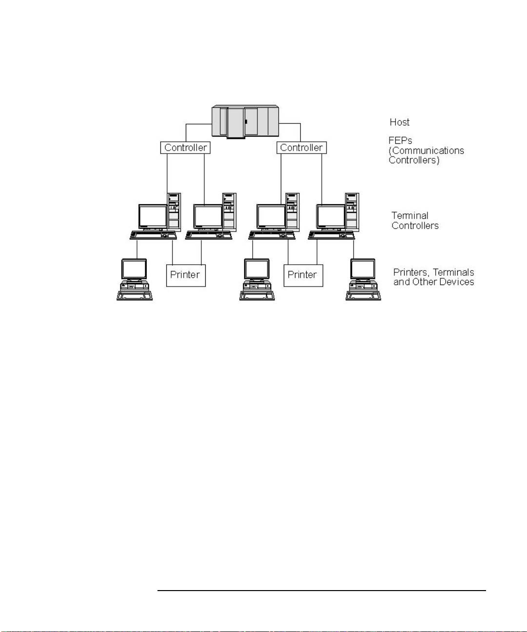
Figure 1-1 SNA Subarea Network
SNA Terms and Concepts
Basic SNA Concepts
The root of the tree (at the top of the diagram) is the computer
controlling the network. The branches are the communications links
from the host to the other computers in the network (terminal
controllers); the leaves (at the bottom of the diagram) are the terminals
or printers attached to these computers, which are accessed by users.
The traditional subarea SNA set-up described here enables the users to
use the resources of a single host system. The terminals provide only
simple data entry and display functions to and from the terminal
controller; the terminal controller is responsible for handling SNA
communications between the terminals and the host.
The terminal controller and its terminals can be replaced by an SNA
node using a product such as SNAplus2. From the host's point of view,
the node appears as a terminal controller. However, it provides the users
with additional functions, such as the ability to access more than one
host system and facilities for customizing screen displays. In addition,
SNAplus2 runs on HP-UX computers that can also be used for other
tasks not related to SNA (unlike the terminal controller, which is used
solely for communications with the host).
Chapter 1 29
Page 30

SNA Terms and Concepts
Basic SNA Concepts
Node Types in a Peer Network
Peer networks do not classify nodes hierarchically, as is done in a
subarea network. Exchanges with other nodes are not controlled by a
host or other centralized processor. Instead, any node can establish
communication with any other node.
A peer network is composed of type 2.1 nodes. The nodes in a peer
network can serve the following roles:
• APPN network nodes (NNs) identify the locations of network
resources, determine routes for sessions between these resources,
route sessions, and serve end nodes (EN) and low-entry networking
(LEN) nodes directly attached to the network node. The domain of an
APPN network node consists of itself and any end nodes for which it
provides network services.
• APPN end nodes can access remote resources without requiring that
those resources be configured on the end node. An end node can
communicate with adjacent nodes on its own, but requires the
services of a network node server to access nonadjacent nodes. The
domain of an APPN end node includes only itself.
• Low-entry networking nodes (LEN nodes) are type 2.1 nodes that do
not support APPN functions. They can communicate with adjacent
nodes in an APPN network, but do not participate in the APPN
network. In a LEN node, all potential sessions with remote LUs must
be predefined, either specifically or through a single default entry
indicating that all remote LUs reside in an adjacent network node
that can be accessed using a certain link. The domain of a LEN node
includes only itself.
For more information about peer-oriented node types, see “APPN Node
Types”.
Connectivity
For two nodes to communicate, each node must have a combination of
hardware and software that supports data flow between the nodes. The
hardware component consists of an adapter at each node and the
transmission medium that connects the two adapters. The software
component provides control of the hardware and the data exchanged over
it.
30 Chapter 1
Page 31

SNA Terms and Concepts
Basic SNA Concepts
Each node connected to a network has one or more link stations, which
are the hardware and software in a node that control data flow to a
specific adjacent node. T o establish communication between two adjacent
nodes, one of the link stations must first activate the link between the
nodes.
Transaction Programs
Programs that exchange information across the SNA network are called
transaction programs (TPs).
Following are examples of application programs that can include SNA
TPs:
• Emulation programs
• File transfer
• Database transaction processing
• Network management
• Centralized data services
The TP accesses the network through a logical unit (LU) that establishes
and maintains a session with a partner LU on another node. For more
information about logical units, see “Logical Units”.
NOTE SNAplus2 includes sample TPs for most supported APIs. For more
information on sample TPs, refer to the programmer's guide for the API.
You can also purchase SNA TPs as part of other products or create your
own TPs (see “Application Programming Interfaces”).
Application Programming Interfaces
SNA TPs are written using application programming interfaces (APIs).
APIs provide specific subroutines that enable SNA TPs to access SNA
functions, such as those for exchanging data and performing control
functions. These subroutines enable an SNA TP to communicate with
another SNA TP on a remote node.
SNAplus2 includes the following APIs on all platforms:
• APPC—LU type 6.2 only
Chapter 1 31
Page 32

SNA Terms and Concepts
Basic SNA Concepts
• CPI-C (Common Programming Interface for Communications)—LU
type 6.2 only
• CSV (Common Service Verb) API
• HLLAPI (high-level language application programming
interface)—as part of the SNAplus2 3270 emulation program
• LUA API
In addition, SNAplus2 includes the following proprietary programming
interfaces (only for HP-UX systems):
• MS (Management Services) API
• NOF (Node Operator Facility) API
For an overview of the APIs provided with SNAplus2, see “Application
Programming Interfaces”.
Network Accessible Units
Communication between a TP and the SNA network occurs through
network accessible units or NAUs (formerly called “network addressable
units”), which are unique network resources that can be accessed
(through unique local addresses) by other network resources.
SNA provides the following types of NAUs:
• Physical units (see “Physical Units”)
• Logical units (see “Logical Units”)
• Control points (see “Control Points”)
NOTE Because TPs are considered users of the network, not components, they
are not classified as NAUs.
Physical Units
Each SNA node contains a physical unit (PU). The PU manages
resources (such as link resources) and supports communication with a
host.
32 Chapter 1
Page 33

SNA Terms and Concepts
Basic SNA Concepts
NOTE On type 2.1 nodes (which can be APPN nodes), the control point provides
PU services in addition to providing other services (see “Control Points”).
Two type 2.1 nodes (such as SNAplus2 nodes) can communicate directly,
without requiring the services of a host to establish communications.
Logical Units
Each SNA node contains one or more logical units (LUs). An LU provides
a set of functions that are used by TPs and end users to provide access to
the network. LUs communicate directly with local TPs and devices.
SNA defines several types of LUs, each optimized for a specific class of
applications. LUs of different types cannot communicate with each other,
but LUs of the same type can communicate even though they reside on
different kinds of systems.
For example, a TP running on a workstation that uses the HP-UX
operating system can communicate with a TP on an AS/400 computer as
easily as it can with a TP on another HP-UX workstation, as long as both
TPs use the same LU type.
SNAplus2 supports the following LU types:
LU 6.2 (for APPC, 5250 and CPI-C)
LU 6.2 supports program-to-program communication
in a distributed data processing environment. The LU
6.2 data stream is either an SNA general data stream
(GDS), which is a structured-field data stream, or a
user-defined data stream. LU 6.2 can be used for
communication between two type 5 nodes, a type 5
node and a type 2.0 or 2.1 node, or two type 2.1 nodes.
(Type 2.1 nodes can serve as APPN nodes.)
This LU type provides more functions and greater
flexibility than any other LU type. Unless you are
constrained by existing hardware or software, LU 6.2 is
the logical choice when developing new applications.
NOTE Only LU 6.2 can provide independent LU functions.
LU 3 (for 3270 printing)
LU 3 supports application programs and printers using
the SNA 3270 data stream.
Chapter 1 33
Page 34

SNA Terms and Concepts
Basic SNA Concepts
For example , LU 3 can support an application program
running under Customer Information Control System
(CICS) and sending data to an IBM 3262 printer
attached to an IBM 3174 Establishment Controller.
LU 2 (for 3270 displays)
LU 2 supports application programs and display
workstations communicating in an interactive
environment using the SNA 3270 data stream. Type 2
LUs also use the SNA 3270 data stream for file
transfer.
For example, the LU 2 protocol can support 3270
emulation programs, which enable workstations to
perform the functions of IBM 3270-family terminals. In
addition, LU 2 is used by other programs to
communicate with host applications that normally
provide output to 3270 display devices. Such TPs
enable the workstation to achieve a form of cooperative
processing with the host.
LU 1 (for 3270 printing and RJE)
LU 1 supports application programs and single- or
multiple-device data processing workstations
communicating in an interactive, batch-data transfer,
or distributed data processing environment. The data
streams used by LU type 1 conform to the SNA
character string or Document Content Architecture
(DCA).
For example, LU type 1 can support an application
program running under Information Management
System/Virtual Storage (IMS/VS) and communicating
with an IBM 8100 Information System. This enables a
workstation operator to correct a database that the
application program maintains.
Applications that use LU 1 are often described as
remote job entry (RJE) applications.
LU 0 (for LUA)
LU 0, an early LU definition, supports primitive
program-to-program communication. Certain host
database systems, such as IMS/VS (Information
Management System/Virtual Storage) and some
point-of-sale systems for the retail and banking
industries (such as the IBM 4680 Store System
34 Chapter 1
Page 35

SNA Terms and Concepts
Basic SNA Concepts
Operating System) use LU 0. Current releases of these
products also support LU 6.2 communication, which is
the preferred protocol for new applications.
NOTE For information about the data streams used by SNA logical units, refer
to Systems Network Architecture Technical Reference.
Control Points
A control point (CP) is an NAU that manages network resources within
its domain, controlling resource activation, deactivation, and status
monitoring. The CP manages both physical resources such as links, and
logical information such as network addresses.
SNA defines the following types of network control points:
System services control point
On a type 5 node, the CP is called a system services
control point (SSCP). It manages and controls the
network resources in a subarea network. For example,
an SSCP can use a directory of network resources to
locate a specific LU under its control, and can establish
communication between two LUs in its domain. An
SSCP can also cooperate with other SSCPs to establish
connectivity between LUs in different subarea
domains.
The SSCP also provides an interface to network
operators at the host system, who can inspect and
control resources in the network.
Physical unit control point
On type 4 nodes and type 2.0 nodes in a subarea
network, the control point is called a physical unit
control point (PUCP).
Control point
On type 2.1 nodes, the control point provides both PU
and LU functions, such as activating local link stations,
interacting with a local operator, and managing local
resources. It can also provide network services, such as
partner LU location and route selection for local LUs.
Chapter 1 35
Page 36

SNA Terms and Concepts
Basic SNA Concepts
In a subarea network, the CP on an SNA node acts as a
type 2.0 PU. It communicates with an SSCP on a host
and does not communicate with other CPs in the
subarea network.
When participating in an APPN network, the CP
exchanges network control information with the CPs in
adjacent nodes. The CP can also function as an
independent LU of type 6.2. The CP acts as the default
LU for TPs on the local node. For more information
about the APPN control point, see “APPN Control
Point”.
Sessions
NAUs communicate with NAUs in other nodes over temporary logical
communication channels called sessions. Before two TPs can
communicate, their LUs must establish a session. The LU that manages
the session on the local node is the local LU; the LU that manages the
session on the remote node is the partner LU.
Session Types
SNAplus2 is primarily concerned with the following types of sessions:
LU-LU sessions
In order for two TPs to communicate, the LUs that
support the TPs must first establish an LU-LU session.
In general, a session is established when a TP in one
SNA node tries to communicate with a TP in another
node and no existing session between the LUs on the
two nodes is available.
SSCP-LU sessions
A dependent LU (see “Dependent and Independent
LUs”) must have an active SSCP-LU session with an
SSCP on a type 5 node before it can have a session with
an LU in the subarea network. Once an SSCP-LU
session is active, a dependent LU can solicit an LU-LU
session.
SSCP-PU sessions
36 Chapter 1
Page 37

SNA Terms and Concepts
Basic SNA Concepts
Before an SSCP-LU session can be established, the PU
controlling the LU must have an active SSCP-PU
session with an SSCP on a type 5 node. The SSCP-PU
session is used to pass control data and network
management data between the PU and SSCP.
CP-CP sessions
In an APPN network, adjacent nodes establish CP-CP
sessions. These sessions are used to search for a
resource in the APPN network and to maintain
topology information (see “APPN Control Point”).
Logical Unit Attributes for Sessions
Logical units have attributes that determine how they interact during
LU-LU sessions. These attributes are determined by the architecture of
SNA. LUs can be primary or secondary, and dependent or independent.
Primary and Secondary LUs. To establish a session, one LU
requests session activation by sending a BIND request to another LU:
• A primary LU is the LU that sends the BIND request for a given
LU-LU session.
• A secondary LU is the LU that receives the BIND request.
Peer networks do not use a fixed hierarchy of nodes and do not have
predetermined primary or secondary LUs.
NOTE In a peer network, an independent LU that is participating in multiple
sessions (see “Multiple and Parallel Sessions”) can act as a primary LU
for one session and a secondary LU in another.
Dependent and Independent LUs. All type 0, 1, 2, and 3 LUs are
dependent LUs. Type 6.2 LUs can be configured as either dependent or
independent LUs.
• A dependent LU (also known as an SSCP-dependent LU) requires the
services of an SSCP to establish a session with another LU. An
SSCP-LU session must be established before a dependent LU-LU
session can be established.
A dependent LU can be in session only with LUs on an SNA host.
Because of this restriction, dependent LUs usually use subarea
networks (also known as host-mediated networks). However, the
Chapter 1 37
Page 38

SNA Terms and Concepts
Basic SNA Concepts
dependent LU requester (DLUR) function enables session traffic from
dependent LUs to flow over APPN networks. For more information
about DLUR, see “Accessing Subarea Networks from APPN
Networks”.
A dependent LU on a peripheral node is always the secondary LU.
• An independent LU can establish sessions with other independent
LUs without the aid of an SNA host. LU 6.2 is the only LU type that
can be independent.
An independent LU can act as a primary or as a secondary LU when
establishing a session.
Multiple and Parallel Sessions
An independent LU can participate in sessions with more than one
remote LU at the same time (multiple sessions).
An independent LU can also participate in parallel sessions, or multiple
concurrent sessions with the same remote LU.
Dependent LUs (including dependent LU 6.2) cannot have multiple
sessions.
LUs with multiple and parallel sessions are shown in Figure 1-2,
“Multiple and Parallel Sessions.” LUA and LUB have parallel sessions.
LUA also has multiple sessions: two with LUB and one with LUD. LUD
has multiple sessions with LUA and LUC.
38 Chapter 1
Page 39

Figure 1-2 Multiple and Parallel Sessions
SNA Terms and Concepts
Basic SNA Concepts
Conversations
This section applies to LU 6.2 only.
Once a session is established between two LUs, the LU-LU session
supports the exchange of information between two TPs, which have the
exclusive use of the session to execute a transaction. This exchange of
information is called a conversation. Only one conversation can use a
particular session at a time, but sessions are serially reusable (many
conversations can use the same session, one after another).
To initiate a conversation, a source TP sends a request to its LU, asking
it to allocate a conversation with a remote TP. The invoking TP (or
source TP) initiates the conversation, like the calling party in a
telephone conversation. The invokable TP or target TP (the remote TP) is
the partner in the conversation, like the party who receives a telephone
call.
Chapter 1 39
Page 40

SNA Terms and Concepts
Basic SNA Concepts
As shown in Figure 1-3, “Communication between Transaction Programs
and Logical Units,” information is exchanged between TPs and LUs to
enable one node to communicate with another. Although the TPs appear
to be communicating directly, the LUs on each node are the
intermediaries in every exchange.
Figure 1-3 Communication between Transaction Programs and Logical
Units
SNA defines two types of conversations: basic and mapped. These two
types of conversations use different methods to indicate the length of
transmitted or received data packages to be passed between SNAplus2
and the TP.
• In a basic conversation, data must be formatted by the TP as logical
records before being presented to the SEND function.
40 Chapter 1
Page 41

A logical record consists of a two- or four-byte header starting with a
two-byte length field, often represented as “LL,” followed by up to
32,765 bytes of data. Logical records can be grouped together and
sent as a block, transmitting more than one logical record with a
single call to the SEND function.
• In a mapped conversation, information is passed to the SEND function
as a pointer to a single, unformatted block of data; the length of the
block is passed as another parameter. The block cannot be received as
one or more logical records; the receiving TP must do whatever
record-level formatting is required.
NOTE Only LU type 6.2 supports mapped conversations.
Modes
Each LU-LU session has an associated mode that defines a set of session
characteristics. These session characteristics include throughput
parameters, session limits (such as the maximum number of sessions
between two LUs), message sizes, and routing parameters.
SNA Terms and Concepts
Basic SNA Concepts
Each mode is identified by a unique mode name. The mode name must be
the same on all SNA nodes that use that mode.
Route Selection
To establish an LU-LU session, a route must be calculated between the
nodes where the two LUs reside. A route is an ordered sequence of links
and nodes that represents a path between the two nodes.
SNA networks support the following methods of route selection:
• For subarea networks , you must predefine all routes between subarea
nodes.
• For peer networks that do not support APPN, type 2.1 nodes can
support sessions only with adjacent nodes; their sessions cannot be
routed through intermediate nodes.
• For APPN networks, SNA can compute routes dynamically at the
time of session initiation, using a class of service specified for the
mode used by the session (see “Class of Service”).
Chapter 1 41
Page 42

SNA Terms and Concepts
Basic SNA Concepts
Class of Service
Class of service (COS) is a definition of the transport network (data link
control and path control) characteristics—such as route security,
transmission priority, and bandwidth—that the local node can use to
establish a particular session. The COS definition assigns relative values
to factors such as acceptable levels of security, cost per byte, cost per
connect-time, propagation delay, and effective capacity.
In a subarea network, a COS is derived from the mode associated with a
session, as defined in the host system.
APPN network nodes use the COS to compute session routes between
independent LUs. For more information about session routing in APPN
networks, see “Session Routing”.
42 Chapter 1
Page 43

SNA Terms and Concepts
Basic APPN Concepts
Basic APPN Concepts
Advanced Peer-to-Peer Networking (APPN) is a network architecture
that supports distributed network control. It makes networks easy to
configure and use, provides centralized network management, and
supports flexible connectivity.
An APPN network is composed of type 2.1 nodes. Each node in the
network is connected by a link to at least one other node in the APPN
network. CP-CP sessions are established over each of these links to
adjacent nodes (nodes in the same network that can establish direct
links without going through a third node). All of the nodes in an APPN
network share a common network name.
APPN nodes can include processors of various sizes, such as the
Application System/400 (AS/400), the Enterprise System/9221 (ES/9221)
running under Distributed Processing Program Executive/370
(DPPX/370), systems using Virtual Terminal Access Method (VTAM),
and HP-UX servers running SNAplus2.
APPN provides the following functions:
• Support for APPN network nodes and end nodes as well as non-APPN
peer nodes (see “APPN Node Types”)
• APPN control point functions (see “APPN Control Point”)
• Directory services to support finding specific logical units (see
“Locating Resources”)
• Topology and routing services to support session establishment using
intermediate session routing (ISR), automatic network routing
(ANR), or connection networks (CNs) (see “Session Routing” and
“APPN Connection Networks”)
NOTE An APPN node can also be connected to a subarea network, serving as
both an APPN node in a peer network and a peripheral node in a subarea
network.
APPN Node Types
The following types of nodes can be part of an APPN network:
Chapter 1 43
Page 44

SNA Terms and Concepts
Basic APPN Concepts
• Network nodes (see “APPN Network Nodes”)
• End nodes (see “APPN End Nodes”)
In addition, low-entry networking (LEN) nodes can be connected to an
APPN network, but they do not use APPN features (see “LEN Nodes”).
A sample APPN network that includes all of these node types is shown in
Figure 1-4, “Portion of a Sample APPN Network.”
Figure 1-4 Portion of a Sample APPN Network
This example shows an APPN network that includes five network nodes
(NNs), three end nodes (ENs), and a LEN node. The network nodes form
the backbone of the APPN network; end nodes access the network
through the network nodes. LU 6.2 TPs on any node can communicate
with any other LU 6.2 TPs in the network.
44 Chapter 1
Page 45

SNA Terms and Concepts
Basic APPN Concepts
One of the APPN network nodes (NNA) also participates in a subarea
network, connecting to a host through a communication controller. This
node functions as an APPN node when communicating with nodes in the
APPN network, and as a peripheral node when communicating with
nodes in the subarea network. Through this network node, LU type 6.2
LUs on other nodes in the APPN network can establish LU-LU sessions
with LU type 6.2 LUs on the host.
APPN Network Nodes
An APPN network node is a type 2.1 node that provides distributed
directory and routing services for all LUs in its domain. These LUs can
be located on the network node itself, or on an APPN end node or LEN
node for which the network node provides services. Because an APPN
network node acts as the network entry point for end and LEN nodes in
its domain, the network node is also referred to as the network node
server for those nodes.
A network node provides the following services:
• LU-LU session services for its local LUs
• Directory searches and route selection for all LUs in its domain
• Intermediate session routing (see “Intermediate Routing”)
• Routing for management services (MS) data, such as alerts, between
a served end node and an MS focal point
APPN End Nodes
An APPN end node is a type 2.1 node that serves as an end point in an
APPN network. It maintains directory information only for local
resources. An APPN end node can independently establish sessions
between local LUs and LUs on adjacent nodes. For sessions with LUs on
nodes not directly connected to the end node, an end node requests
routing and directory information from its network node server using
CP-CP sessions.
APPN end nodes can register their local LUs with their network node
server. This capability means the network operator at the network node
server does not have to predefine the names of all LUs on the attached
end nodes to which the network node provides services.
Chapter 1 45
Page 46

SNA Terms and Concepts
Basic APPN Concepts
An APPN end node can be attached to multiple network nodes (see EN3
in Figure 1-4, “Portion of a Sample APPN Network,”) but it can have
CP-CP sessions active with only one network node at a time—its
network node server. The other network nodes can be used only to
provide intermediate routing for the end node or as substitute network
node servers if the main network node server becomes unavailable.
An APPN end node can also have a direct link to another APPN end node
or a LEN node, but CP-CP sessions are never established between two
end nodes.
LEN Nodes
A low-entry networking node (LEN node) is a type 2.1 node that uses
independent LU 6.2 protocols, but does not support CP-CP sessions. It
can be connected to an APPN network node or end node, but does not
support APPN functions.
An APPN network node can provide routing services for an attached
LEN node, enabling the LEN node to participate in an APPN network
without requiring link stations to be defined between the LEN node and
all of the nodes in the APPN network.
LUs in the APPN network with which the LEN node may want to
establish sessions must be defined to the LEN node as if they reside on
the LEN node's network node server. The LEN node establishes sessions
with LUs on its network node server. The network node routes the
session through the APPN network to the node in the network where the
LU actually resides. LUs on the LEN node must be predefined to the
network node that serves the LEN node. LU resources on LEN nodes
(unlike those on end nodes) cannot be registered on the network node
server.
An APPN end node cannot provide intermediate routing. When a LEN
node's only link is to an APPN end node, the LEN node can communicate
only with LUs on the end node through the direct link between the two
nodes.
46 Chapter 1
Page 47

SNA Terms and Concepts
Basic APPN Concepts
APPN Control Point
An APPN control point is a set of functions that manages node resources
and supports both physical unit and logical unit functions on a type 2.1
node. An APPN CP directs local node functions (such as activating and
deactivating adapters and links), provides directory and topology
information, and assists LUs in session initiation and termination.
Adjacent nodes in an APPN network use a pair of parallel CP-CP
sessions to exchange network information and to provide directory and
route selection services. Both sessions of a given pair must be active in
order for the partner CPs to begin and sustain their interactions.
Different node types use these sessions differently, as follows:
• Two parallel CP-CP sessions are established between an APPN
network node and each adjacent network node. These CP-CP sessions
are used to exchange directory, topology, and management services
data.
• Two parallel sessions are established between an APPN end node and
the adjacent network node acting as the server for the end node.
These CP-CP sessions are used to exchange directory, topology, and
management services data.
• LEN nodes do not support CP-CP sessions.
The functions provided in CP-CP sessions vary based on the types of
nodes involved, as follows:
• All CP-CP sessions conduct directory searches.
• CP-CP sessions between an end node and a network node provide the
following functions:
• Registering resources.
• Routing management services data (such as alerts) between the
end node and a focal point.
• Routing topology data from each end node to its network node
servers. This information can be used by the network node server
to compute a route that does not flow through the network node
server.
• CP-CP sessions between adjacent network nodes exchange topology
information. As a result of this exchange, each network node creates
an internal network topology database.
Chapter 1 47
Page 48

SNA Terms and Concepts
Basic APPN Concepts
When setting up a workstation, you must define the CP name. The CP is
also an LU that can support user sessions, and it can be the only LU
defined in your workstation, if you so choose.
Locating Resources
To support communication between TPs, SNAplus2 first establishes a
session between the logical units that control those TPs. APPN enables
the CP on a node to locate LUs throughout the APPN network without
requiring that the node have any configuration information for the
remote LU. The APPN function that dynamically locates LUs in the
network is called directory services. Once a resource has been located, a
route for the session is calculated through the APPN network.
Resource Names
Each node has a unique name consisting of two parts: a network name
and a control point name. Together they constitute a fully qualified CP
name. This name identifies each node to all other nodes in the network.
Similarly, each logical unit is identified by a fully qualified LU name,
consisting of a network name and LU name.
Directory Services
Each APPN node maintains a directory of network resources. Directory
services is the component of the node CP that manages the local
directory database and, in a network node, searches for network
resources throughout an APPN network.
When the node is initialized, it includes the following information:
• Node type (APPN network node, APPN end node, or LEN node)
• Network ID of node
• CP name of node
Each node directory maintains entries for resources (LUs and CPs),
including each resource's fully qualified name, type, and registration
status. The specific resources stored in each local directory depend on the
node type:
• A LEN node maintains a directory that includes its own LUs. It must
also be configured with directory entries for all of its possible partner
LUs. LUs in the APPN network with which the LEN node may want
to establish sessions must be defined to the LEN node as if they
48 Chapter 1
Page 49

SNA Terms and Concepts
Basic APPN Concepts
reside on the LEN node's network node server. The LEN node
establishes sessions with LUs on its network node server. The
network node routes the session through the APPN network to the
proper node in the network.
A LEN node can also use wildcards in a directory entry to specify
multiple partner LUs that can be accessed over a specific link.
• An APPN end node maintains a directory that includes its own LUs.
It can also be configured to store directory entries for partner LUs in
adjacent nodes. This enables local LUs to establish peer-to-peer
sessions with those LUs without using APPN functions.
If a resource is not locally defined to an end node or currently cannot
be reached by the end node, the end node sends a request to its
network node server asking it to search the APPN network for the
resource.
• An APPN network node maintains a directory that includes its own
LUs and the end node and LEN node LUs in its domain. An end node
can dynamically register its LUs with its network node server. (LEN
nodes cannot register LUs with a network node server, so LEN node
LUs must be configured on their network node server.) A network
node directory can also contain cached entries for LUs that are not in
the network node's domain, but whose location has been determined
through a previous search.
Network nodes provide directory services to other nodes in two ways:
• Searching for remote resources in response to session requests
from end nodes or LEN nodes
• Responding positively to directory search requests from other
network nodes when a named resource is found in the local
directory
LEN Node Directories. An example of a LEN node directory is
shown in Figure 1-5, “LEN Node Directory.” Since LEN nodes do not
support CP-CP sessions, the directory for Node LEN1 must contain all
the LUs with which it communicates. The directory for Node LEN1
identifies its network node server (NNA) as the location for any LUs that
are not on an adjacent peer end node. Since Node LEN1 can access the
LUs only through Node NNA, it defines the CP on the network node as
the “owning CP” of all the LUs, including LUs located on the end nodes.
Chapter 1 49
Page 50

SNA Terms and Concepts
Basic APPN Concepts
Figure 1-5 LEN Node Directory
To establish a session with an LU on a node that is not directly attached,
Node LEN1 sends an LU-LU session activation (BIND) request to its
network node server (Node NNA). The server automatically locates the
destination LU and forwards the BIND.
NOTE In this example, Node LEN1 can establish a session with LU1 on Node
EN1 through its network node server, NNA. However, LU2 on Node EN1
is not defined in the directory for Node LEN1, so Node LEN1 cannot
establish sessions with that LU.
End Node Directories. When an LU is not represented in an end
node directory, the end node initiates a LOCATE search to find the desired
LU. To activate the search for a remote LU, the end node invokes the
services of its network node server. An example of an end node directory
is shown in Figure 1-6, “End Node Directory.”
50 Chapter 1
Page 51

Figure 1-6 End Node Directory
Potential partner LUs in the APPN network do not need to be defined to
the end node. However, in order for Node EN3 to establish a session with
LUX on Node LEN1, the LU on the LEN node must be configured as a
partner LU on Node EN3.
SNA Terms and Concepts
Basic APPN Concepts
Network Node Directories. A network node provides distributed
directory services to the end nodes it serves.
An example of a network node directory is shown in Figure 1-7,
“Network Node Directory.”
Chapter 1 51
Page 52

SNA Terms and Concepts
Basic APPN Concepts
Figure 1-7 Network Node Directory
A network node locates a remote LU as follows:
1. The network node receives a request to locate an LU. The request can
be any of the following:
• The name of a destination LU sent by an end node or a LEN node
to its network node server
• An LU name specified in a LOCATE search request from an end
node
• An LU name specified in a BIND request from a LEN node
• An LU name specified by a TP on the network node
2. If the destination LU is not located in the network node—but appears
in its directory—the network node sends a directed search request to
the destination network node server to verify the location of the LU.
If the LU is not in the network node directory, the node initiates a
search of the network by sending a broadcast search to every adjacent
network node.
3. Each node in turn propagates the broadcast and returns replies
indicating success or failure.
For its future needs, a network node caches information obtained from
successful broadcast searches.
52 Chapter 1
Page 53

SNA Terms and Concepts
Basic APPN Concepts
An APPN end node can also receive (and respond to) LOCATE search
requests from its network node server to search for, or confirm the
continued presence of, specific LUs in the end node.
Each APPN end node registers its LUs with its network node server by
sending the network node a registration message. In this way, the
network node maintains current directory information for the end nodes
in its domain. A LEN node cannot register LUs with its network node
server. Therefore, all LUs on the LEN node must be predefined, through
configuration, to the network node server.
Session Routing
APPN supports the following dynamic route selection procedures:
• For sessions with adjacent nodes, direct session routing.
• For sessions that traverse one or more intermediate nodes, one of the
following:
• Intermediate session routing (ISR), which provides a route that
does not change during the course of the session.
• High-Performance Routing (HPR), which includes the Rapid
Transport Protocol (RTP) and automatic network routing (ANR)
facilities. RTP enables you to reroute session traffic around route
failures or congestion, and ANR minimizes cycles and storage
requirements for routing network layer packets through
intermediate nodes on a session route.
The APPN functions that provide dynamic route selection are known as
topology and routing services (TRS).
Topology and Routing Services
Each APPN node includes a topology database that stores information
about other APPN nodes and about transmission groups, which are sets
of links between a specific pair of nodes. The contents of the database for
a specific node depend on the node type:
• All network nodes share a copy of the network topology database.
This shared database includes information about all other network
nodes—including network IDs, CP names, and other node
characteristics—and about the transmission groups between each
pair of network nodes. This database provides a complete view of the
Chapter 1 53
Page 54

SNA Terms and Concepts
Basic APPN Concepts
network backbone topology—the nodes and transmission groups that
can be used for routing sessions between any pair of nodes in the
network.
In addition, the topology database on each network node contains
local information about transmission groups from that network node
to adjacent end nodes or LEN nodes.
The network node uses the topology database to calculate routes for
sessions between LUs in its domain and remote LUs, or to provide
information to other network nodes to enable them to calculate
session routes.
• Each end node has a local topology database with information about
transmission groups from that end node to adjacent nodes.
The end node provides this information to its network node server as
part of the request to locate an LU and calculate a session route to
that LU. The network node server uses the end node topology
information when calculating the session route for the end node. The
end node uses this information when establishing sessions with
predefined LUs on adjacent nodes. The end node topology database
supports communication only with adjacent nodes.
NOTE APPN network nodes and end nodes also maintain topology information
about links to a connection network (see “APPN Connection Networks”).
LEN nodes maintain local topology information. They do not forward this
information to a network node server.
As shown in Figure 1-8, “Network Topology Database in Network
Nodes,” network topology information is replicated at all network nodes,
and local topology information is stored at network nodes and end nodes.
54 Chapter 1
Page 55

Figure 1-8 Network Topology Database in Network Nodes
SNA Terms and Concepts
Basic APPN Concepts
The shared network topology database is duplicated at Nodes NNA,
NNB, NNC, and NND. In addition, each of those nodes includes local
topology information (except Node NNC, which does not have any local
Chapter 1 55
Page 56

SNA Terms and Concepts
Basic APPN Concepts
topology information because it does not have any links to end nodes).
For example, Node NNB includes information for Link f to Node EN2
and Link g to Node EN3, but it does not include information for Link i,
which connects Nodes EN2 and EN3.
End nodes include information only for links to adjacent nodes. For
example, Node EN2 includes information about Link f to Node NNB and
Link i to Node EN3.
Topology Database Updates. APPN network nodes use CP-CP
sessions to exchange network topology information when a resource
(such as a node or a link between two network nodes) is activated or
deactivated, or when the characteristics of an existing resource change.
When such a change occurs, a network node generates a topology
database update (TDU) that contains node identification node and link
characteristics, and update sequence numbers identifying the resource to
be updated and the changes for the resource. Each TDU is sent to all
active network nodes to ensure that the network topology database is
kept current throughout the network.
Route Selection in an APPN Network. APPN directory services
locates a specific session partner; topology and routing services
calculates the optimal session route after the session partner has been
located in the network. Each network node provides route selection
services for sessions originated by its own LUs and by LUs at the end
nodes or LEN nodes that it serves. A network node uses its own local
topology information, plus information from the shared network topology
database, to dynamically calculate routes between nodes.
Once the session partner has been located, the network node performs
the following steps to select a route:
1. Obtains required characteristics for the session route.
The LU requesting the session specifies a mode name that identifies
session characteristics. The associated mode identifies a class of
service that specifies requirements for the links used to route session
traffic.
2. Obtains all transmission groups and network nodes for possible
routes:
• If the session request comes from an end node, the end node
provides information about links it has to its network node server
and to a connection network, if one exists.
56 Chapter 1
Page 57

SNA Terms and Concepts
Basic APPN Concepts
• If the session partner is not on an adjacent node, the network node
server for the LU requesting the session uses the network topology
database to identify network nodes and intermediate transmission
groups in the route to the session partner.
• If the session partner is on an end node, the end node (or its
network node server) provides information about the link between
the network node server and that end node (or the link between
the end node and a connection network).
3. Excludes all network nodes and transmission groups that do not meet
the specified characteristics for the session route.
4. Computes the optimal route for the session.
Depending on the specified class of service, the route calculation
algorithm computes a weight value for each node and logical link and
then totals the weights for each route. To select the optimal path, the
network node computes the current least-weight route from the node
containing the originating LU to the node containing the destination LU.
Intermediate Routing
Intermediate routing enables an APPN network node to receive and
route data destined for another node. The origin and destination of the
data can be an end node, another network node, or a LEN.
Intermediate routing supports sessions between LUs that are not on
adjacent nodes. After a route has been selected for a session, APPN
network nodes in the route use intermediate routing to forward session
data to the next node in the route.
Resource characteristics maintained by the topology database can
include congestion status. If a network node becomes heavily congested,
the network node can relay this information to other network nodes in
the network, making the congested network node less likely to be
included in session routes calculated for new sessions.
APPN provides two types of intermediate routing:
• In intermediate session routing (ISR), available in all network nodes,
the network node keeps track of each intermediate session. Each
intermediate node adjusts the pacing of session data to control the
rate at which data flows between adjacent nodes. Each intermediate
node can also perform segmentation and reassembly of segmented
Chapter 1 57
Page 58

SNA Terms and Concepts
Basic APPN Concepts
data. In ISR, once a session route has been established, all data on
that session uses the same route. If part of the route fails, the session
ends.
• In automatic network routing (ANR), available in network nodes that
support APPN's High-Performance Routing (HPR) function,
intermediate network nodes can dynamically reroute session traffic if
part of the route fails. ANR does not provide intermediate session
pacing or segmentation and reassembly.
ANR enables intermediate nodes to route session traffic much faster
than is possible with traditional APPN ISR. However, ANR requires
additional overhead at the RTP (Rapid Transport Protocol) endpoints. In
routes with few intermediate nodes, an ANR route might actually be
slower than an ISR route, due to processing time at the endpoints. For
routes containing a larger number of intermediate nodes (hops), ANR
routes are typically faster. The exact location of the break-even point
depends on the efficiency of the RTP nodes.
Direct Connectivity
Direct connectivity enables session traffic to travel directly between two
nodes without the need for an APPN network node to route the session.
In general, sessions between directly connected nodes can exchange data
more quickly than sessions for which data is routed through a network
node. For nodes on a shared-access transport facility (SATF)—for
example, for nodes on a token ring as shown in Figure 1-9—efficiency
would be increased by defining links between every pair of nodes in your
network. However, this can be a difficult task—the number of link
stations is n × (n−1), where n is the number of nodes in the network.
An APPN network on a token ring is shown in Figure 1-9, “APPN
Network Using a Shared-Access Transport Facility.”
58 Chapter 1
Page 59

SNA Terms and Concepts
Basic APPN Concepts
Figure 1-9 APPN Network Using a Shared-Access Transport Facility
If Node EN1 has a link definition for each of the links in the network, it
can establish a direct link to any node. The link definitions needed to
support direct links between Node EN1 and every other node in the
APPN network are shown in Figure 1-10, “Definitions Needed for Direct
Links from Node EN1 to Every Node in an APPN Network.” For a
network that includes five other nodes, Node EN1 needs five link
definitions:
• EN1 to NNA
• EN1 to EN2
• EN1 to EN3
• EN1 to EN4
• EN1 to EN5
Chapter 1 59
Page 60

SNA Terms and Concepts
Basic APPN Concepts
Figure 1-10 Definitions Needed for Direct Links from Node EN1 to Every
Node in an APPN Network
If all of the nodes in the network are to support direct links to every
other node, a total of 30 link definitions are needed on the six nodes in
this example. In general, the number of link definitions can be calculated
as n × (n−1), where n is the number of nodes in the network. In a larger
network, the number of link definitions quickly becomes unwieldy.
Increasing the number of link definitions between network nodes also
increases the number of TDUs flowing through the network, which can
degrade network performance.
APPN connection networks provide a solution to this problem.
APPN Connection Networks
For APPN networks attached to a shared-access transport facility
(SATF), an APPN connection network greatly reduces the number of link
definitions needed to support direct connectivity between nodes in the
network. In a connection network, an APPN end node needs to configure
60 Chapter 1
Page 61

SNA Terms and Concepts
Basic APPN Concepts
only a single link to an adjacent network node server and a link to the
connection network, instead of configuring every possible link to every
node.
To use the connection network feature , an APPN network must meet the
following conditions:
• The nodes in the APPN network must be linked using switched media
such as token ring or Ethernet (see “DLCs”).
• All of the links in the APPN network must use the same media.
• The APPN network that contains the connection network must be
fully connected. In a fully connected network, each node has at least
one link that supports CP-CP sessions to an adjacent node.
In a connection network, the SATF serves as a virtual routing node
(VRN) that attaches directly to each node in the connection network. The
name of the connection network serves as the name of the control point
for the VRN. The VRN supports the direct routing of session data
between any two nodes in the connection network, but it does not
establish CP-CP sessions with other nodes and it does not generate
TDUs. Each node in the connection network requires only a link to its
network node server.
The link definitions needed when using a connection network are shown
in Figure 1-11, “Definitions Needed for Direct Links Using a Virtual
Node.” By using a virtual node, the connection network supports direct
links between Node EN1 and every other node in the APPN network, yet
it requires only two link definitions.
Chapter 1 61
Page 62

SNA Terms and Concepts
Basic APPN Concepts
Figure 1-11 Definitions Needed for Direct Links Using a Virtual Node
To support direct links between any two end nodes in the APPN network,
a total of ten link definitions is required. (Each end node needs two link
definitions: one to a network node server and one to the virtual node.)
Compared to the direct connectivity requirements for an APPN network
that does not use a connection network (see Figure 1-10), you can have a
much smaller number of link definitions (10 instead of 30 in this
example). In a larger network, the difference in definition requirements
becomes even more substantial.
A session between LUs on two nodes in the connection network is
established as follows:
1. Each end node first establishes CP-CP sessions with its network node
server. (If two end nodes have different network node servers, those
network nodes must have a link that supports CP-CP sessions.)
2. End nodes also report their VRN links and local address information
to the network node server. The local address information can be a
service access point (SAP) address and a medium access control
(MAC) address.
62 Chapter 1
Page 63

SNA Terms and Concepts
Basic APPN Concepts
3. The server normally selects the direct link between two end nodes as
the optimal route for the LU-LU session. It provides the node with
the primary LU the information it needs to establish a dynamic link
to the node with the partner LU.
4. The end nodes can then establish an LU-LU session without the need
for intermediate session routing.
Chapter 1 63
Page 64

SNA Terms and Concepts
Accessing Subarea Networks from APPN Networks
Accessing Subarea Networks from
APPN Networks
Although APPN networks do not require a host to control resources in
the network, hosts often participate in APPN networks. APPN has been
implemented on many host platforms, and allows the hosts to perform as
network nodes in the APPN network while still providing an SSCP to
control any old subarea SNA function.
Many SNA networks contain elements of both subarea SNA and APPN.
The backbone of the network is built from network nodes that must
bridge the gap between a dependent LU and the facilities on the host.
Two additional services are required to achieve this:
• Dependent LU server (DLUS) on the host provides access to the old
SSCP functions and interfaces to the APPN network.
• Dependent LU requester (DLUR) on a network node or end node
provides a means of transporting session traffic from dependent LUs
to a host through an APPN network. This function enables dependent
LU sessions to take advantage of the more versatile routing functions
provided by APPN.
This combination of DLUR and DLUS (generally known simply as
DLUR) allows dependent LU traffic to be transported over the APPN
backbone. Existing SNA applications that use dependent LUs can be
retained without modification, while taking advantage of APPN's
network management, dynamic resource location, and route selection
capabilities. In this way, DLUR provides a useful migration path from
subarea SNA to APPN.
The dependent LU does not need to reside on the node that provides the
DLUR function. If the DLUR function is provided by a network node, the
dependent LU can be on an adjacent network node, end node, or LEN
node. If the DLUR function is provided by an end node, the dependent
LU must be on the end node itself.
64 Chapter 1
Page 65

2 Introduction to SNAplus2
65
Page 66

Introduction to SNAplus2
Overview
Overview
This chapter provides an overview of SNAplus2 features and shows some
of the basic configurations in which SNAplus2 can be used. It describes
the major components of SNAplus2 and the SNA resources that are
configured for and used by SNAplus2, and provides an overview of
SNAplus2 administration responsibilities and tools.
66 Chapter 2
Page 67

Introduction to SNAplus2
What Is SNAplus2?
What Is SNAplus2?
SNAplus2 is a software product that enables HP-UX computers to
participate in an SNA network that includes mainframes, PCs, and other
HP-UX computers. With SNAplus2, you can access data and programs
that reside on other computer systems, thereby increasing your
computing power.
SNAplus2 includes the following facilities:
SNA communication facilities
SNAplus2 nodes can operate within an SNA subarea
network, within an APPN network, or within both at
the same time. For more information about SNA
support supplied by SNAplus2, see “SNA Support”.
Passthrough services
SNAplus2 includes services that support
communication between a host and computers on a
LAN, making it possible to reduce the number of
communication links to the host, simplify configuration
of SNA nodes, and provide host access for computers
that have no direct link to a host. F or more information
about passthrough services, see “Passthrough
Services”.
User applications
SNAplus2 supports the following user applications:
• 3270 emulation
• 5250 emulation
• Remote job entry (RJE)
For more information about user applications, see
“User Applications”.
Application programming interfaces
SNAplus2 includes application programming
interfaces (APIs) that you can use to write user
application programs or SNAplus2 administration
programs. F or more information about SNAplus2 APIs ,
see “Application Programming Interfaces”.
LAN facilities
Chapter 2 67
Page 68

Introduction to SNAplus2
What Is SNAplus2?
Within a TCP/IP local area network (LAN), SNAplus2
supports communication between servers (SNA nodes)
and clients (HP-UX or Windows computers). For more
information about client/server facilities on a LAN, see
“Client/Server Support”.
Windows clients
For Windows SNAplus2 provides support for Windows clients
(running Windows 3.11, Windows for Workgroups,
Windows 95, and Windows NT), enabling them to
access SNA resources through SNAplus2 servers. The
APIs provided for Windows clients support 3270 and
5250 emulation and enable the development of custom
applications. These APIs implement the WOSA
standards and are compatible with the APIs provided
with Microsoft's SNA Server.
End of Section
Administration facilities
SNAplus2 includes several methods and tools you can
use to configure and manage SNAplus2 servers and
clients. For more information about SNAplus2
administration, see “Client/Server Support”.
68 Chapter 2
Page 69

Introduction to SNAplus2
Example Configurations
Example Configurations
SNAplus2 can be used as a standalone system to support direct
communication with a host or another SNA node, within a LAN to
support SNA communications across the LAN, or as a gatew ay to support
communication between a host and systems in a LAN.
A computer running SNAplus2 configured as a standalone system that
communicates directly with a host computer is shown in Figure 2-1,
“Standalone SNAplus2 Node That Communicates Directly with a Host.”
Figure 2-1 Standalone SNAplus2 Node That Communicates Directly with a
Host
Several SNAplus2 nodes configured as an APPN network are shown in
Figure 2-2, “SNAplus2 Nodes in an APPN Network.” SNA is used for
peer communication within the LAN as well as over the SDLC link.
Chapter 2 69
Page 70

Introduction to SNAplus2
Example Configurations
Figure 2-2 SNAplus2 Nodes in an APPN Network
In Figure 2-3, “SNAplus2 Node Providing PU Concentration and DLUR,”
a computer running SNAplus2 provides TN server support for TN3270
and TN3270E clients. The TN server node and the clients communicate
through the TCP/IP network.
70 Chapter 2
Page 71

Introduction to SNAplus2
Example Configurations
Figure 2-3 SNAplus2 Node Providing PU Concentration and DLUR
In Figure 2-4, “SNAplus2 Node Configured for TN Server,” a computer
running SNAplus2 provides TN server support for TN3270 and
TN3270E clients. The TN server node and the clients communicate
through the TCP/IP network.
Chapter 2 71
Page 72

Introduction to SNAplus2
Example Configurations
Figure 2-4 SNAplus2 Node Configured for TN Server
A network that includes SNA nodes (SNAplus2 servers) and non-SNA
computers (SNAplus2 clients) is shown in Figure 2-5, “SNAplus2
Client/Server Configuration.” The clients can access SNA resources
through the servers.
72 Chapter 2
Page 73

Figure 2-5 SNAplus2 Client/Server Configuration
Introduction to SNAplus2
Example Configurations
These examples show the most basic ways in which you can configure
SNAplus2 nodes. By combining nodes using these basic configuration
types, you can use SNAplus2 to support different types of communication
within more complex networks.
Chapter 2 73
Page 74

Introduction to SNAplus2
SNAplus2 Components
SNAplus2 Components
The components of SNAplus2 and their relationships are shown in
Figure 2-6, “Components of SNAplus2.”
Figure 2-6 Components of SNAplus2
The local node—including its associated connectivity resources (DLCs,
ports, and link stations)—is implemented as a set of STREAMS
components in the kernel of the HP-UX system.
The 3270 emulation program, RJE workstation, APPC transaction
programs, CPI-C applications, LUA applications, and the remote
command facility (RCF) are user-space programs. SNAplus2 supports
multiple copies of the 3270 and 5250 emulation programs, and multiple
APPC TPs, CPI-C applications, and LUA applications running
concurrently.
74 Chapter 2
Page 75

Introduction to SNAplus2
SNAplus2 Components
Node Components
A server running SNAplus2 implements an SNA node. It can also
provide passthrough services between an SNA host and computers in an
APPN or TCP/IP network.
SNA Support
SNAplus2 provides SNA node type 2.0 and 2.1 (LEN node) support for
communicating with host and peer computers; it also implements an
APPN node, providing end node function.
SNAplus2 implements an APPN node to communicate with other nodes
on the SNA network. This provides logical unit (LU) 6.2 support for
APPC and CPI-C capabilities and for 5250 emulation, in addition to LU
0, 1, 2, and 3 support for 3270, RJE, and LUA communications.
SNAplus2 can operate either as a LEN node or as an APPN end node,
depending on its configuration. Certain functions are supported only on
end nodes, as defined by the APPN architecture. These differences are
indicated where necessary in this manual; where no differences are
indicated, the information applies to both node types.
Passthrough Services
Passthrough services enable downstream computers on a LAN to access
host resources through a server running SNAplus2. SNAplus2 provides
the following passthrough services:
• PU concentration (see “PU Concentration”).
• Dependent LU requester (see “Dependent LU Requester”).
• TN server (see “TN Server”).
• UNIX command facility (see “Remote Command Facility”).
PU Concentration. In addition to providing direct access to a host
computer, SNAplus2 can provide PU concentration facilities. This
feature enables other computers to access a host computer through the
SNAplus2 node, instead of requiring a separate connection to the host
from each computer.
The PU concentration feature is shown in Figure 2-7, “PU
Concentration.”
Chapter 2 75
Page 76

Introduction to SNAplus2
SNAplus2 Components
Figure 2-7 PU Concentration
The downstream computer must contain an SNA PU type 2.0 or 2.1 to
support dependent LUs. F or example, the downstream computer could be
a PC running Microsoft SNA Server for Windows NT, or another
SNAplus2 computer.
When the local SNAplus2 node uses the PU concentration feature, all the
data transferred between the host and the downstream computer is
routed through the local node. This enables a downstream computer to
share a host connection with SNAplus2 or with other downstream
computers, instead of requiring a direct link. For example, you could set
up several downstream computers connected to SNAplus2 over a local
token ring network, so that they could all access the same long-distance
leased line from SNAplus2 to the host.
Using PU concentration also simplifies the configuration at the host,
because you do not need to define the downstream computers and the
communication links to them. The host configuration needs to include
only the SNAplus2 computer and its host communication link; the LUs
76 Chapter 2
Page 77

Introduction to SNAplus2
SNAplus2 Components
at the downstream computers are configured as part of the resources of
the SNAplus2 computer. The host computer is not aware that PU
concentration is being used.
Dependent LU Requester. This section does not apply to LEN
nodes.
In addition to providing direct access to a host computer, SNAplus2 can
provide dependent LU requester (DLUR) facilities. This feature enables
sessions for dependent LUs to span multiple nodes in an APPN network,
instead of requiring a direct connection to the host.
DLUR on the SNAplus2 node works in conjunction with dependent LU
server (DLUS) at the host. Together, they route sessions across the
network from dependent LUs in the APPN network to the DLUS host.
The route to the host can span multiple nodes and can take advantage of
APPN's network management, dynamic resource location, and route
calculation facilities.
TN Server. 3270 emulation programs that communicate over TCP/IP
(rather than over an SNA network) are referred to as TN3270 programs
(Telnet 3270 emulation programs).
TN3270 programs can also include support for TN3270E (Telnet 3270
standard extensions). TN3270E supports 3270 device emulation
(including both terminals and printers) using Telnet. It enables a Telnet
client to select a particular device (by specifying the LU name), and
provides enhanced support for various functions, including the ATTN
and SYSREQ keys and SNA response handling.
Chapter 2 77
Page 78

Introduction to SNAplus2
SNAplus2 Components
NOTE This guide uses the term TN3270 for information that applies equally to
the TN3270, TN3287, and TN3270E protocols.
SNAplus2 TN server provides access to 3270 host computers for TN3270
users on other computers. TN server enables TN3270 users to share a
host connection with SNAplus2 or with other TN3270 users, instead of
requiring a direct link. TN server also enables TN3270 users to access
hosts that are not running TCP/IP.
The SNAplus2 TN server function is shown in Figure 2-8, “TN Server.”
Figure 2-8 TN Server
TN server provides an association between a TN3270 user and a 3270
LU on the SNAplus2 server. All data from the TN3270 user is routed to
the LU. This means that the configuration for both the host and the
TN3270 user is as though they were connected directly; neither needs to
be aware that data is being routed through TN server.
78 Chapter 2
Page 79

Introduction to SNAplus2
SNAplus2 Components
SNAplus2 TN server supports all TN3270 client emulation programs
that correctly implement the protocols defined in RFCs 1123, 1576, 1646,
and 1647.
When a TN3270 program communicates with TN server, SNAplus2
identifies the program by the TCP/IP address of the computer where the
TN3270 program is running. SNAplus2 cannot distinguish between two
different TN3270 programs being used by different users on the same
computer. In the SNAplus2 manuals, the term TN server user refers to
the computer where a TN3270 program is running, not to an individual
user of that program.
Each TN server user is normally configured to access a single 3270 LU,
and so is restricted to one host session at a time. However, you can also
configure a TN server user to access a pool of 3270 LUs, instead of having
a single dedicated 3270 LU for each user. This enables the user to access
as many sessions as there are available LUs in the pool.
User Applications
SNAplus2 supports the following user applications:
• 3270 emulation programs (see “3270 Emulation”).
• 5250 emulation programs (see “5250 Emulation”).
• RJE workstation daemon (see “RJE Workstation Daemon”).
3270 Emulation
You can use 3270 emulation software to log on to and use SNA host
systems from your computer, control display and printer emulation
sessions, and to transfer files between the local and host computers. 3270
emulation uses the node's LU type 0–3 resources.
To use 3270 emulation, you need to define the 3270 users on your system,
identified by their login IDs, and the 3270 features available to each user
or group of users. 3270 users and sessions are defined as domain
resources, which simplifies the configuration required to support
emulation across the domain.
The SNAplus2 3270 emulation program provides session control and file
transfer capabilities. In addition, you can customize some 3270
emulation features, such as key-mapping and display attributes.
SNAplus2 3270 emulation also enables you to use HLLAPI applications.
Chapter 2 79
Page 80

Introduction to SNAplus2
SNAplus2 Components
Refer to the HP-UX SNAplus2 3270/3179G Users Guide for information
about using the 3270 emulation software to communicate with a host.
For more information about configuring support for 3270 emulation, see
Chapter 8, “Configuring User Applications.”
5250 Emulation
Using 5250 emulation software, you can log on to and use AS/400
systems from your computer. You can use emulation software to control
display and printer emulation sessions and to transfer files between the
local computer and the AS/400. 5250 emulation uses the node's LU type
6.2 resources.
NOTE SNAplus2 does not provide a 5250 emulation program; it just provides
support for third party 5250 emulation software.
To use 5250 emulation with SNAplus2, you need to define the 5250 users
on your system. 5250 users are defined as domain resources, which
simplifies the configuration required to support emulation across the
domain.
Depending on the requirements of the 5250 emulation program you use,
you may need to configure the emulation program with additional
information.
For more information about configuring support for 5250 emulation, see
Chapter 8, “Configuring User Applications.”
RJE Workstation Daemon
SNAplus2 provides support for remote job entry (RJE), enabling you to
submit jobs to a host computer for processing. The RJE workstation
daemon is the SNAplus2 component that handles transfer of jobs to the
host, and also handles the output returned from the host.
You can prepare jobs for submission to the host and add them to the
queue for an RJE workstation at any time, regardless of whether the
RJE workstation is running. When the workstation runs, it submits any
outstanding jobs to the host (in the order in which they were submitted).
It also routes any output received from the host to the appropriate
destination, as determined by the configuration.
The RJE workstation uses the node's LU type 0–3 resources. In addition,
you need to define (as domain resources) the RJE workstations on your
system.
80 Chapter 2
Page 81

Introduction to SNAplus2
SNAplus2 Components
The users of an RJE workstation can define workstation style files to
supplement the SNAplus2 configuration and to control the operation of
the workstation.
Refer to the HP-UX SNAplus2 RJE Users Guide for information about
using RJE to submit jobs to a host and about setting up the workstation
style file.
Application Programming Interfaces
SNAplus2 provides several standard programming interfaces that you
can use to develop application programs:
• APPC API for peer-to-peer communications between application
programs (see “APPC API”).
• CPI-C (Common Programming Interface for Communications) for
platform-independent communication using independent LU 6.2 (see
“CPI-C API”).
• CSV (Common Service Verb) API for utility functions such as
character translation and application trace control (see “CSV API”).
• HLLAPI (high-level language application programming interface) for
application programs that interact with the 3270 emulation program
to automate standard 3270 tasks (see “HLLAPI”).
• LUA API for communications with host applications (see “LUA API”).
In addition, SNAplus2 includes the following proprietary programming
interfaces:
• MS (Management Services) API for network messaging functions (see
“MS API”).
• NOF (Node Operator Facility) API for applications that configure and
manage SNAplus2 resources (see “NOF API”).
For Windows Windows client APIs (see “Windows APIs”).
End of Section
For more detailed information about an API, refer to the programming
guide for the API (see “SNAplus2 Publications”).
Chapter 2 81
Page 82

Introduction to SNAplus2
SNAplus2 Components
APPC API
An APPC application uses the node's LU type 6.2 resources to
communicate with another APPC or CPI-C application on a host or peer
computer, using a specified mode. The APPC API includes TP server
support, enabling applications to have greater control over starting
transaction programs (TPs) and distributing conversations to those TPs.
If the TP on the SNAplus2 computer is the invoking TP (the TP that
starts the APPC conversation), the additional node resources required
depend on the APPC features used by the TP, and on the type of remote
system it is communicating with:
• If the local node or the remote system with which the TP
communicates is a LEN node, you need to define directory entries for
the remote node and its LUs.
• If the TP specifies its local APPC LU using an LU alias, you need to
define the partner LU in order to associate this alias with a fully
qualified LU name.
• If the TP uses a dependent local LU to communicate with a host, you
need a partner LU definition on the local node that specifies the
uninterpreted name for the LU on the host. When the TP requests a
conversation from the local LU, the local LU sends the host a session
initialization request that contains the uninterpreted name for the
host LU.
In the Motif administration program, directory entries and partner LUs
are not shown explicitly, but are included under the “Remote Systems”
heading in the Node window for the local node.
If the TP on the SNAplus2 computer is the invoked TP (the TP that
accepts a conversation started by the invoking TP), the additional
resources required depend on the APPC features used by the TP, and on
how it is to be started:
• To restrict the TP to using particular options for conversation
security, confirm synchronization, or conversation type (mapped or
basic), or to restrict the number of instances of the TP that can be
running at any time, you must define the TP as a node resource.
• To start the TP automatically when another TP requests a
conversation with it, you must provide the information that
SNAplus2 needs to start the TP. For more information, see Chapter 7,
“Configuring APPC Communication.”
82 Chapter 2
Page 83

Introduction to SNAplus2
SNAplus2 Components
• If the TP is operator-started (not started automatically by SNAplus2),
and the use of the TP does not need to be restricted, you do not need
to define any additional resources. The only exceptions are when you
want to do the following:
• Change the default timeout for a RECEIVE_ALLOCATE issued
by the TP.
• Specify that the TP is a broadcast queued TP (which means that
incoming conversation requests can be routed dynamically to the
TP wherever it is running).
For more information about TP configuration, see “Defining TPs”.
For more information about the APPC API, refer to the HP-UX
SNAplus2 APPC Programmers Guide.
CPI-C API
A CPI-C application uses the node's LU type 6.2 and mode resources to
communicate with another APPC or CPI-C application on a host or peer
computer. You define the same resources for a CPI-C application as for
an APPC application, as described in “APPC API”.
In addition, if the TP on the SNAplus2 computer is the invoking TP (the
TP that starts the conversation), you may need to define one or more side
information entries for it. Each of these entries provides information
about a partner TP, the LU and mode resources used to access the
partner TP, and any security information required.
For more information, refer to the HP-UX SNAplus2 CPI-C
Programmers Guide.
CSV API
The Common Service Verb (CSV) API provides utility verbs that enable
an application program to perform functions such as character set
conversion and trace file control.
For more information, refer to the HP-UX SNAplus2 CSV Programmers
Guide.
HLLAPI
HLLAPI (high-level language application programming interface)
enables applications that use the SNAplus2 3270 emulator program to
communicate with a host.
Chapter 2 83
Page 84

Introduction to SNAplus2
SNAplus2 Components
For more information, refer to the HP-UX SNAplus2 3270 & TN3270
HLLAPI Programmers Guide or HP-UX SNAplus2 3270/3179G Users
Guide.
LUA API
The LUA API enables application programmers to write applications
that communicate with host applications at the request unit and
response unit (RU) level, and to send and receive data on both the
SSCP-LU session and the PLU-SLU session. This API can be used to
support LU 0, 1, 2, or 3 communication with the host.
An LUA application uses the node's LU type 0–3 resources to
communicate with a host application. You do not need to define any
additional resources.
For more information, refer to the HP-UX SNAplus2 LUA Programmers
Guide.
MS API
The Management Services (MS) API enables an application to
communicate with other MS products in an APPN network. An
application can be either NMVT-level or MDS-level, depending on the
type of MS data it sends and receives. SNAplus2 performs any data
conversion that is required.
For more information, refer to the HP-UX SNAplus2 MS Programmers
Guide.
NOF API
The NOF API can be used to write applications that administer
SNAplus2 configuration and management resources. For more
information, refer to the HP-UX SNAplus2 NOF Programmers Guide.
Windows APIs
For Windows The SNAplus2 client software includes API libraries that are fully
compatible with Microsoft SNA Server and the Windows Open Systems
Architecture (WOSA), enabling applications written for SNA Server to
run unchanged on the SNAplus2 Windows client.
SNAplus2 supports the following WOSA APIs:
• Windows APPC
84 Chapter 2
Page 85

End of Section
Introduction to SNAplus2
SNAplus2 Components
• Windows CPI-C
• Windows LUA
• Windows CSV
• 3270 Emulator Interface Specification
For more information about Windows SNA APIs, see the documentation
provided with Microsoft SNA Server.
Client/Server Support
Computers running SNAplus2 can be configured to communicate using
client/server protocols. When client/server protocols are used in a
network, all the computers using client/server protocols to communicate
in that network are referred to as a domain. Each computer in the
network specifies the same domain name when SNAplus2 is installed.
The computers running SNAplus2 in a client/server configuration can
take the following roles:
• A server contains an SNA node and its associated connectivity
components. The server provides SNA connectivity to applications on
the local system or on other machines in the same domain.
• A client does not contain SNA components, but accesses them
through a server. A client can access one or more servers at the same
time, and can run concurrent applications as needed.
Servers must be HP-UX computers; clients can be running HP-UX or
Windows. Servers and clients communicate across the SNAplus2 domain
using TCP/IP.
You can configure one or more separate SNAplus2 domains on the same
physical network, using a unique name for each different domain. Use
the same domain name for all SNAplus2 servers and clients that belong
the same domain. A single SNAplus2 domain can correspond to a TCP/IP
subnet, can be part of a TCP/IP subnet (so that there are two or more
separate SNAplus2 domains in the same subnet), or can span multiple
subnets.
Each server maintains information about its own node configuration in a
node configuration file. You can use the SNAplus2 administration tools,
described in “Administration Tools”, to examine and modify the node's
Chapter 2 85
Page 86

Introduction to SNAplus2
SNAplus2 Components
configuration. You can configure a node from any other computer in the
domain, as long as the SNA software is running on the node where the
configuration is performed (whether or not the node being configured is
started).
Information about the configuration of domain resources for the complete
SNAplus2 LAN is held in a domain configuration file. If you have more
than one server on the LAN, SNAplus2 ensures that this domain
configuration information is consistent across all servers.
Benefits of Client/Server Operation
Client/server configuration provides the following benefits:
• Concentrating SNA resources on servers reduces the load on clients,
improving client performance and minimizing the storage needed to
provide SNA services to clients.
• Sharing a single data link among multiple users on different
machines eliminates the need for each machine to have a physical
SNA network connection.
• Having multiple servers provides redundant connectivity (for
example, by having multiple servers providing access to the same
host). Having multiple paths to an SNA resource enables load
balancing across the different servers and provides immediate
backup in the event that a particular server or link fails.
• Using LU pools across multiple servers makes it easy to configure
and add servers and users.
• Having fewer links and PUs for host connectivity reduces the size of
the host VTAM definition.
• Using SNAplus2 administration utilities makes it easy to configure
and manage both node resources (for any specific computer in the
domain) and shared resources (across the domain). The client/server
support provided by SNAplus2 administration tools enables
transparent administration of all domain resources from any
computer in the domain.
Master Server and Backup Servers
If you are using SNAplus2 with all programs on one computer, or on a
LAN that contains only one server, you do not need to read this section.
86 Chapter 2
Page 87

Introduction to SNAplus2
SNAplus2 Components
In a domain with multiple SNAplus2 servers, one server holds the
master copy of the SNAplus2 domain configuration file. This server is
known as the master server. You can define other servers on the LAN to
be backup servers. The domain configuration file is copied to backup
servers—either when they are started, or when the master copy is
changed—so that all backup servers hold a copy of the latest
information.
In general, you should define at least one backup server in addition to
the master server. Any remaining servers can be defined as additional
backup servers, or they can be left as peer servers. A peer server obtains
domain configuration information from the master server as required,
but cannot act as a backup server.
If the master server fails, the first backup server on the list of servers
defined for the domain takes over as the master. The domain
configuration file on this server is used as the master copy, and is copied
to other servers as necessary. When the master server is restarted, it
receives a copy of the domain configuration from the backup server
currently acting as master, and then takes over as the master.
If at any time the master server and all backup servers are inactive, a
node on a peer server can still operate, and you can still change the
node's configuration. However, you cannot access the domain
configuration file, and therefore cannot access the configuration of
domain resources (as opposed to node resources). This means that you
cannot start the 3270 emulation program, start the RJE programs, or
allocate CPI-C conversations using symbolic destination names defined
in the configuration file.
NOTE If the LAN is split by a network failure into two noncommunicating
domains, each containing one or more backup servers, SNAplus2 cannot
maintain a consistent configuration of domain resources across the LAN.
In this situation, each domain has an acting master server , each trac king
changes made to the domain configuration file in its own domain but
unaware of any changes made in the other domain. When the LAN
connection is re-established, the domain configuration file from the
original master server becomes the domain configuration file across the
LAN, and any domain resource files on other servers are overwritten. (If
the master is inactive at this point, the domain configuration file from
the highest backup server available in either of the two domains is used.)
Because changes to a domain configuration file are not necessarily
Chapter 2 87
Page 88

Introduction to SNAplus2
SNAplus2 Components
preserved when the connection is re-established, do not make any
changes to the file in either domain while the LAN connection is broken.
Changes can still be made to the configuration of individual nodes.
SNAplus2 stores information about the master server and backup
servers in the file sna.net, known as the SNA network data file. The
master copy of this file is stored on the master server; any changes made
to it are automatically copied to all other servers in the same way that
changes to the domain configuration file are copied to backup servers.
You cannot edit the contents of the SNA network data file directly;
instead, SNAplus2 provides administration facilities to access the file.
(You can edit node configuration files directly when SNAplus2 is not
running; but in general you should use SNAplus2 administration
facilities to ensure that all configuration information is valid and
internally consistent.)
For more information about the SNA network data file, refer to the
HP-UX SNAplus2 Administration Command Reference.
HP-UX Clients
For UNIX A client computer does not contain a configuration file or SNA network
data file. Instead, the client has a client network data file that holds the
information it needs to access servers on the SNAplus2 LAN. The client
relies on a server to provide the necessary configuration information.
Most of the details of using HP-UX client computers are the same as
those for a server, except that the client has no node resources to define
and manage. The following references provide more details about using a
client:
• To start and stop the SNAplus2 software, see Chapter 3,
“Administering SNAplus2.”
• To set up information required to support invokable TPs on the client,
see “Defining TPs”.
• To manage the SNA network information required to access servers
on the SNAplus2 LAN, see Chapter 11, “Managing SNAplus2
Clients,” or refer to the HP-UX SNAplus2 Administration Command
Reference.
• To manage diagnostics information (logging and tracing), see
“Diagnostic Tools”, or for more detailed information, refer to the
HP-UX SNAplus2 Diagnostics Guide.
88 Chapter 2
Page 89

Introduction to SNAplus2
SNAplus2 Components
End of Section
Windows Clients
For Windows SNAplus2 enables machines running Microsoft Windows 3.1, Windows
for Workgroups 3.11, Windows 95, Windows NT, and OS/2 to act as
clients in the SNAplus2 domain. You can run either a 16-bit version of
the SNAplus2 client software (referred to in this guide as “Win16”) or a
32-bit version (referred to in this guide as “Win32”):
• The 16-bit version can be installed on machines running Windows 3.1
or Windows for Workgroups 3.11, or on Win16 subsystems on
Windows NT, Windows 95, or OS/2. SNA network information, and
other configuration information required by Win16 clients, is held in
the sna.ini file.
• The 32-bit version can be installed on machines running Windows 95
or Windows NT. Configuration information required by Win32 clients
is managed through the Windows Program Registry.
For more information about the sna.ini file and the Windows Program
Registry, and about managing Windows clients, see Chapter 11,
“Managing SNAplus2 Clients.” For information about Windows SNA
APIs, see “Windows APIs”, or refer to the documentation provided with
Microsoft SNA Server.
End of Section
Chapter 2 89
Page 90

Introduction to SNAplus2
SNAplus2 Resources
SNAplus2 Resources
The resources of the SNAplus2 system can be divided into the following
types:
• Node resources define the communications capabilities of a particular
APPN node. The following are node resources:
• Connectivity resources including the following:
• DLCs
• Ports
• Link stations
• Connection networks
• Session resources including the following:
• LUs (types 0–3 for 3270, RJE, and LUA communications, and
type 6.2 for APPC and CPI-C communications and for 5250
emulation)
• Modes and their associated classes of service
• Directory information
• Domain resources are additional resources that are available to all
nodes (not defined as part of a particular node) to support specific
user programs. Domain resources include the following:
• 3270 user information
• 5250 user information
• RJE workstation information
• CPI-C side information
• Logging levels
• Information about access to the UNIX command facility and
service point command facility
The following sections describe the various SNAplus2 resources, and
explain how those resources work together to support each type of user
program.
90 Chapter 2
Page 91

Introduction to SNAplus2
SNAplus2 Resources
NOTE Some of the resources listed here do not appear in the Motif
administration program, or are presented differently. These differences
are indicated in the following sections where they apply.
Connectivity Resources
Connectivity to remote systems is supported by the following resources:
• DLCs (see “DLCs”).
If you use the Motif administration program to configure a port, the
corresponding DLC definition is created automatically. For
command-line administration, the DLC is configured separately.
• Ports (see “Ports”).
• Link stations (see “Link Stations”).
• Connection networks (see “Connection Networks”)
If you use the Motif administration program, you can define a
connection network as part of port configuration. For command-line
administration, a connection network is configured separately.
DLCs
A DLC is the component responsible for communication over a physical
link (or multiple links) using a specific data link protocol, such as SDLC
or token ring. Each DLC can manage one or more ports, as described in
“Ports”.
SNAplus2 provides support for the following data link protocols:
• Synchronous data link control (SDLC)
• X.25 QLLC (qualified logical link control), for which the X.25
communications software may be provided by your SNAplus2
supplier or by another supplier
• Token ring
• Ethernet (standard or IEEE 802.3)
• FDDI (Fiber Distributed Data Interface)
Chapter 2 91
Page 92

Introduction to SNAplus2
SNAplus2 Resources
NOTE In the Motif administration program, DLCs are not shown directly. The
information required for configuring a DLC is displayed as part of the
configuration of a port owned by the DLC.
Ports
A port represents the local end of a communications link as a unique
access point in the network. In general, this corresponds to a single
physical access point such as an adapter card. However, some link
protocols (such as token ring) enable you to define multiple ports for a
single adapter; in this case, the different ports are distinguished by
addresses (such as the SAP address).
Each port is associated with a specific DLC. One or more ports can use
the same DLC.
Link Stations
A link station represents the logical path through the SNA network
between the SNAplus2 local node and a remote computer. The remote
computer can be any of the following:
• A host computer on which SNAplus2 accesses a host program using
3270, RJE, or LUA communications (or uses APPC or CPI-C for
program-to-program communications)
• A peer computer with SNAplus2 and the remote computer
communicating as equal partners (the typical arrangement in an
APPN network)
• A downstream computer that uses the SNAplus2 PU concentration
feature or DLUR feature as a gateway to access a host.
A link station is associated with a specific port. One or more link stations
can be defined on the same port.
Connection Networks
Connection networks cannot be used by LEN nodes.
Nodes that are connected to the same token ring, Ethernet, or FDDI
network have a direct communications path between all nodes, so that in
theory any two nodes can communicate directly. Such a network is
referred to as a shared-access transport facility (SATF).
92 Chapter 2
Page 93

Introduction to SNAplus2
SNAplus2 Resources
The local node can have an explicit link station defined for its
communication path to another node on the SATF, but enabling
communications between every pair of nodes on the SATF requires a
large number of link station definitions, and results in a large volume of
network topology information flowing on the network.
APPN enables you to set up this type of configuration without having to
define each link station explicitly, by defining a connection network (CN)
that represents the SATF. For each node on the SATF, you define one or
more ports used to access the connection network. Instead of defining a
link station to each remote node, you specify the name of a virtual
routing node (VRN) as part of the port definition.
You can think of the VRN as an imaginary node that represents all the
other nodes on the SATF; you can give it any name you like, but all nodes
on the SATF must use the same VRN name (and it must not match the
name of any of the real nodes on the SATF). The local node can establish
communications with any other node that has a port associated with the
same CN, by accessing the VRN (which represents all the other nodes
attached to the SATF), instead of requiring an explicitly defined
communications path between each pair of nodes.
When two nodes on the SATF need to communicate and both have a port
defined with the same VRN name, APPN can dynamically establish a
direct connection between them; you do not need any additional
configuration.
Because the connection is direct and does not need to go through any
intermediate nodes, using a connection network reduces traffic on the
LAN and improves performance. You should use connection networks
wherever possible to take advantage of this.
You can define CNs for communications using token ring, FDDI or
Ethernet DLCs.
To use this feature, you first define a DLC and port for each node that
accesses the SATF, and indicate that the port should be defined on the
connection network. You do not need to define any link stations;
SNAplus2 sets up a dynamic link station to the CN (and hence to any
port on it) when required.
NOTE In the Motif administration program, CNs are not shown as a separate
resource, but are included as part of the configuration of SATF ports.
Chapter 2 93
Page 94

Introduction to SNAplus2
SNAplus2 Resources
Session Resources
The following session resources are used by SNAplus2:
• Logical units (see “Logical Units”)
• Modes and their associated classes of service (see “Modes and Classes
of Service”)
• Directory information (see “Directory Information”)
Logical Units
An LU is the node's point of contact with a user program (3270
emulation program, RJE workstation, APPC TP, CPI-C application, or
LUA application). LUs are divided into two categories:
Dependent LUs
Type 0–3 LUs are referred to as dependent LUs; they
can support only one user session at a time, and a
session is controlled by the host program. Type 6.2 LUs
can also be dependent LUs if they are used to
communicate with host computers running older
versions of SNA host software.
LU types 0–3 are sometimes referred to as “old LUs,”
and are used to communicate with hosts using 3270
emulation, RJE,or LUA.
Type 0–3 LUs can also be grouped into LU pools, as
described in “LU Pools”. In addition, dependent type
6.2 LUs can be assigned to default pools, as described
in “Default LUs”.
Independent LUs
LU type 6.2 is used to communicate with either hosts
or peer computers using APPC or CPI-C.
Type 6.2 LUs that are used to communicate with peer
computers, or with newer SNA software on host
computers, are referred to as independent LUs.
Independent LUs can support multiple user sessions
simultaneously.
Dynamic Definition of Dependent LUs. Dynamic definition of
dependent LUs (DDDLU) is a host feature that enables dependent LUs
on the SNA system to be added to the host configuration when the
communication link from the SNA system to the host is established.
94 Chapter 2
Page 95

Introduction to SNAplus2
SNAplus2 Resources
With DDDLU, LUs do not have to be configured statically at the host.
(You must still define dependent LUs on the SNAplus2 node.) This
reduces the initial configuration required at the host, and makes later
expansion easier.
SNAplus2 can communicate with both DDDLU-capable and
non-DDDLU-capable hosts, with no difference in the configuration
required. When the communications link from the SNAplus2 node to the
host is established, a DDDLU-capable host informs the node that it
supports DDDLU; the node then sends the required information to
define the dependent LUs that use the link. If the host is not
DDDLU-capable, SNAplus2 does not send this information; it assumes
that the LUs have already been defined statically at the host.
LU Pools. Type 0–3 LUs can also be grouped into LU pools, so that a
user session can be assigned to a pool of LUs. For 3270, RJE, and LUA
applications, you can use LU pools to simplify configuration and give
greater flexibility.
All of the LUs in a pool must be the same type. For example, you can
define several 3270 display LUs in a single LU pool, then configure
multiple 3270 display sessions using this LU pool. This makes
configuring 3270 sessions easier and enables any 3270 session to use any
LU in the pool.
LU pools can also span multiple SNAplus2 servers—just define LU pools
with identical names on the different servers. Clients that use the LU
pool can then use any server. This means that the clients can still be
used if a server fails or is taken out of service. Using LU pools also
simplifies client configuration and makes it easy to increase capacity by
adding another server or by adding LUs on an existing server.
LU pools support the following operations:
• Assigning LUs to users on a “first come, first served” basis when there
are more users than LUs.
• Balancing the traffic from user sessions across multiple servers or
multiple host links, by defining a pool containing LUs on more than
one node or on more than one host link.
• Permitting access to more than one host system from the same
configuration, so that if one host system becomes unavailable,
sessions can still be established to another system without requiring
reconfiguration.
Chapter 2 95
Page 96

Introduction to SNAplus2
SNAplus2 Resources
Default LUs. If you are configuring type 6.2 dependent LUs for use
with APPC or CPI-C applications, you may wish to define them as
members of the default pool. The default pool can include LUs from more
than one node. An application that does not specify a particular local LU
is assigned an unused LU from the pool of default LUs.
An application requesting a default LU can be assigned to any of these
LUs as available; the LU does not need to be on the same computer as
the application. However, if you are defining partner LUs for the
applications, the partner LUs must be defined on all nodes where default
LUs are defined, so that the application can contact the correct partner
LU using any of the default local LUs defined on any node.
Modes and Classes of Service
A mode specifies a set of characteristics that a type 6.2 local LU uses to
communicate with its partner LU. These characteristics include
information about the way data is transmitted between the two LUs
(such as maximum RU size and pacing window sizes), and about whether
the LUs can establish parallel sessions.
The definition of a mode can also include the name of a class of service
(COS), which specifies minimum and maximum acceptable values for
characteristics such as transmission time, transmission cost, and
network security, together with weightings associated with different
ranges of these values. This enables the node to calculate the best route
across the network when two or more routes to the same remote LU are
available. The configuration of the SNAplus2 node specifies whether the
node performs explicit mapping between modes and COSs. If explicit
mapping is not supported, you do not need to associate a COS with the
mode; the COS name is determined dynamically.
Directory Information
APPN network and end nodes maintain dynamic directory information
about remote nodes and partner LUs. In addition, you can configure such
information directly. On a LEN node, you must configure directory
entries for each partner LU. You can also configure such resources
directly on an APPN end node or network node (for example, to eliminate
the need for a network node to locate a frequently used resource).
96 Chapter 2
Page 97

Introduction to SNAplus2
SNAplus2 Resources
Domain Resources
Information about domain resources such as 3270 users, RJE
workstations, access to the remote command facility, CPI-C side
information, and logging levels may be needed anywhere in the network.
For this reason, only one definition is required for each such resource .
Chapter 2 97
Page 98

Introduction to SNAplus2
SNAplus2 Administration
SNAplus2 Administration
As the SNAplus2 administrator, you are responsible for installing the
SNAplus2 software and for managing its resources.
Before beginning SNAplus2 administration, you must understand the
main features of the SNAplus2 product. This section describes the
administration tasks you must perform and the tools you can use to
perform them.
Administration Responsibilities
To administer the SNAplus2 system, you need to do the following:
Step 1. Define the resources of the SNAplus2 system, as required by the user
programs that will be running. Work with the administrators of the host
or peer computers with which SNAplus2 communicates, to ensure that
the SNAplus2 configuration matches that of the remote system.
Step 2. Initialize the SNAplus2 software.
Step 3. Optionally, modify the configuration dynamically as your requirements
change—by adding or removing resources, or by activating and
deactivating the defined resources.
Step 4. Monitor the status of active resources and gather diagnostics
information to diagnose any problems that occur.
Step 5. Optionally, create application programs or shell scripts to automate
standard management operations.
These tasks are normally performed by a System Administrator at the
site where the SNAplus2 system is installed. However, SNAplus2 also
provides the service point command facility (SPCF), which enables an
operator using the NetView program to perform Steps 3 and 4 remotely
by issuing management commands at the NetView console. For more
information about SPCF, see Chapter 10, “Managing SNAplus2 from
NetView.”
98 Chapter 2
Page 99

Introduction to SNAplus2
SNAplus2 Administration
Administration Tools
SNAplus2 provides a range of tools for administering the system.
Depending on your requirements, you may not need to use all of them.
This section summarizes the functions provided by each of these tools.
NOTE This document provides general information about SNAplus2
administration, which you can perform using any of the tools described
in this section. For most purposes, the Motif administration program is
recommended, because it provides context-sensitive guidance for node
configuration and management.
SNAplus2 includes the following administration tools:
• Motif administration program (see “Motif Administration Program”).
• Command-line administration program (see “Command-Line
Administration Program”, or refer to the HP-UX SNAplus2
Administration Command Reference).
• Service-point command facility (see “Remote Command Facility”).
• Configuration files (see “Configuration Files”).
• Diagnostic tools (see “Diagnostic Tools”).
• Simple Network Management Protocol (see “Simple Network
Management Protocol Support”).
All of the SNAplus2 administration tools use the NOF API. You can also
use that API to write your own administration tools. For more
information, see “NOF Applications”.
Motif Administration Program
The easiest way to define and modify the SNAplus2 configuration is to
use the Motif administration program (xsnapadmin). This program
provides a graphical user interface from which you can view and manage
SNAplus2 resources.
The following management operations are available:
• Defining SNAplus2 resources
• Starting and stopping a node and its connectivity resources
• Changing the configuration of defined resources
Chapter 2 99
Page 100

Introduction to SNAplus2
SNAplus2 Administration
• Querying the configuration of defined resources and their current
status if they are active
• Deleting resources
The Motif administration program can be used to manage both node
resources (for any server on the LAN, as long as the SNAplus2 software
is running on that server) and domain resources. For each type of
communications (such as 3270 or APPC), the program guides you in
setting up the configuration of the required resources.
NOTE The windows and dialogs in the Motif administration program may differ
from those shown in this guide, depending on the functions included with
your installation of SNAplus2 and the choices you make on a particular
dialog.
The Motif administration program includes help screens that provide
overview information for SNA and SNAplus2, reference information for
SNAplus2 dialogs, and guidance for performing specific tasks.
Before starting the Motif administration program, make sure the
SNAplus2 software is enabled. For more information, see Chapter 3,
“Administering SNAplus2.”
To start the Motif administration program in the background, issue the
following command:
xsnapadmin &
All started SNAplus2 servers are shown on the main screen. For those
that have already been configured, the program enables you to select a
node, and then displays the selected node's configuration. Otherwise, the
program prompts you to select a node and leads you through the
required steps to define it.
For more information about how to use the Motif administration
program to define and manage SNAplus2 resources, see “Invoking the
Motif Administration Program”, or refer to the help screens provided by
the program.
NOTE The Motif administration program enables you to set up all required
parameters for standard SNAplus2 configurations. For advanced
parameters, the Motif administration program supplies default values.
You need to supply only the essential configuration information, which
enables you to set up SNA communications quickly and easily.
100 Chapter 2
 Loading...