

Page 1

HP 64784
H8/3003 Emulator
Terminal Interface
User’s Guide
HP Part No. 64784-97010
August 1995
Edition 6
Page 2

Page 3

Notice Hewlett-P ac kar d ma kes no war r anty of any kind with rega rd to
this materia l, inc ludi ng, but not limi te d to, the implied warranties
of merchantabil ity and fitne ss for a parti cul ar purpo se.
Hewlett-Pa c ka rd sha ll not be liabl e fo r errors c ont a ined he rei n or for
incident al or conse que nt ia l dama ges in c onn ect ion with the furn ishi ng,
perfo rmance, or use of this mat erial.
Hewlett-Pa c kard assum es no responsibility for the use or reliabil ity of
its software on equ ipme nt that is not furni she d by Hewle tt-Packard.
© Copyright 1995, Hewlett-Pac ka rd Co mp an y.
This docume nt conta i ns prop rie t ar y information, which i s prot ec ted by
copyrigh t. All righ ts are rese rv ed . No part of this doc um e nt may be
photocopie d, reprod uc ed or transl ate d to ano ther l anguage without the
prior written co nse nt of Hewl ett- Pac ka rd Compa ny. The infor mat ion
contained in this document is subject to change without notice.
HP is a tradem ark of Hewlett -P a c ka rd Com pa n y .
UNIX is a registere d trade m ark in the Unit ed Sta tes a nd ot he r
countries, lic en sed exclusiv el y throug h X/Ope n Comp an y Lim ited .
H8/3003 is a registered trademark of Hitachi Ltd.
Hewlett-P ac kar d Com pany
P.O. Box 219 7
1900 Garden of the Gods Road
Colorado Springs, CO 80901-2197, U.S.A.
RESTRICTED RIGHTS LEGEND Use, duplication, or discl osure
by the U.S. Governm ent is subjec t to restr icti ons se t forth in
subparag raph (C) (1) (ii) of the Rights i n Tec hni c al Dat a and Com put er
Software Cla use at DFARS 252.22 7-7013. Hewlett-Packard Compa ny,
3000 Hanove r Str eet , Palo Alto, CA 94304 U. S. A. Ri ght for non-DOD
U.S. Gov ernmen t De partment and Agencies are as set fort h in F AR
52.227-19 (c)(1, 2) .
Page 4

Printing History New editions a re complete re vi sions of the man ua l. The date on the
title page changes only when a new edition is published.
A software code may be printe d be fore the dat e; this indicates the
version leve l o f the software produ ct at the ti m e t he manual was issued.
Many produc t up da te s an d fix es do not requ ire manua l cha nge s, and
manual corre c ti ons m ay be done without accompa nyi ng pr oduc t
changes. There fo re , do not expe c t a one-t o-on e corr espondence
between pro duc t upda te s an d manu al re visi ons.
Edition 1 64784-97000 , July 1993
Edition 2 64784-97002 , March 199 4
Edition 3 64784-97004 , August 19 94
Edition 4 64784-97006 , April 1995
Edition 5 64784-97008 , May 1995
Edition 6 64784-97010 , Aug 1995
Page 5

Using This Manual
This manua l is desi gne d to giv e you an introdu ct ion to the HP 64784
H8/3003 Emulat or. This man ua l will also help defi ne how these
emulators differ from othe r HP 64700 Emulat ors.
This manua l will :
This manua l wi ll not:
give you an introduc tion to using the emul ator
explore various ways of applying the emul a tor to accomplish
your tasks
show you emulator comm ands whi ch are spe cifi c to the
H8/3003 Emulator
tell you how to use each and every emulator/analyzer
command (refer to the User’s Reference m anual)
Page 6

Organization
Chapter 1 An introduc tion t o the H8/3003 emul at or fea tu re s and how they ca n
Chapter 2 A brief introduct io n to using the H8/30 03 E mula to r. You will load
Chapter 3 How to plug the emulator probe into a ta rget syste m .
Chapter 4 Configuri ng the em ulat or to adapt it to your speci fic me asu re ment
Appendix A H8/3003 Emulator Specific Command Syntax and Error Message
help you in developi ng new ha rdwa re and software.
and execute a short progra m , and make som e measu re ment s usin g the
emulation analyzer.
needs.
Page 7

Contents
1 Introductio n to the H8/300 3 Emulato r
Introduction . . . . . . . . . . . . . . . . . . . . . . . . . . . . . . 1-1
Purpose of the H8/3003 Emulator . . . . . . . . . . . . . . . . . . 1-1
Features of the H8/3003 Emulator . . . . . . . . . . . . . . . . . . 1-3
Supported Mic roprocessors . . . . . . . . . . . . . . . . . . . . 1-3
Clock Speeds . . . . . . . . . . . . . . . . . . . . . . . . . . . 1-5
Emulation memory . . . . . . . . . . . . . . . . . . . . . . . . 1-7
Analysis . . . . . . . . . . . . . . . . . . . . . . . . . . . . . . 1-7
Registers . . . . . . . . . . . . . . . . . . . . . . . . . . . . . . 1-7
Breakpoints . . . . . . . . . . . . . . . . . . . . . . . . . . . . 1-7
Reset Support . . . . . . . . . . . . . . . . . . . . . . . . . . . 1-8
Real Time Operation . . . . . . . . . . . . . . . . . . . . . . . 1-8
Limitations, Restricti ons . . . . . . . . . . . . . . . . . . . . . . . 1-9
Foreground Mo nit or . . . . . . . . . . . . . . . . . . . . . . . . 1-9
DMA Support . . . . . . . . . . . . . . . . . . . . . . . . . . . 1-9
Internal RAM of H8/3005 . . . . . . . . . . . . . . . . . . . . . 1-9
Watch Dog Tim e r in Background . . . . . . . . . . . . . . . . . 1-9
Monitor Bre ak at Sleep/Standby Mode . . . . . . . . . . . . . . 1-9
Hardware Standby Mode . . . . . . . . . . . . . . . . . . . . . 1-9
Interrupts in Background Cycles . . . . . . . . . . . . . . . . . 1-9
Reset Output Enable Bit . . . . . . . . . . . . . . . . . . . . . . 1-9
Evaluation chip . . . . . . . . . . . . . . . . . . . . . . . . . 1-10
2 Getting Started
Introduction . . . . . . . . . . . . . . . . . . . . . . . . . . . . . . 2-1
Before You Begin . . . . . . . . . . . . . . . . . . . . . . . . . . . 2-2
A Look at the Sample Program . . . . . . . . . . . . . . . . . . . . 2-3
Using the Help Fa c il it y . . . . . . . . . . . . . . . . . . . . . . . . 2-7
Initialize the Em ula t or to a Known State . . . . . . . . . . . . . . . 2-8
Set Up the Proper Emulation Configuration . . . . . . . . . . . . . 2-9
Set Up Emulation Conditions . . . . . . . . . . . . . . . . . . . 2-9
Mapping Me mory . . . . . . . . . . . . . . . . . . . . . . . . . . 2-11
Contents- 1
Page 8

Transfer Code into Emulat ion Memory . . . . . . . . . . . . . . 2-12
Transferri ng Co de from a Term inal
In Standalone Configuration . . . . . . . . . . . . . . . . . . 2-12
Transferri ng Co de From A Host,
HP 64700 In T ra nsparent Confi guration . . . . . . . . . . . . 2-15
Looking a t Your Code . . . . . . . . . . . . . . . . . . . . . . . 2-18
Familiarize Yourself with the System Prompts . . . . . . . . . . 2-19
Running the Sample Program . . . . . . . . . . . . . . . . . . . 2-20
Stepping Through the Program . . . . . . . . . . . . . . . . . . . 2-22
Tracing Pro gram Execution . . . . . . . . . . . . . . . . . . . . 2-22
Predefine d Tr ac e La be ls . . . . . . . . . . . . . . . . . . . . . 2-22
Predefine d Status Equate s . . . . . . . . . . . . . . . . . . . . 2-23
Specifying a Trigge r . . . . . . . . . . . . . . . . . . . . . . . 2-23
Using Softwar e Br ea kpoints . . . . . . . . . . . . . . . . . . . . 2-27
Displaying and Modifying the Bre ak Conditions . . . . . . . . 2-27
Defining a Software Bre akpoint . . . . . . . . . . . . . . . . . 2-28
Searching Memory for Str ings or Numeric Expressions . . . . . . 2-29
Making Progr am Coverage Measurements . . . . . . . . . . . . . 2-29
Trace Ana lysis Considerations . . . . . . . . . . . . . . . . . . . 2-30
How to Specify th e T rigger Condition . . . . . . . . . . . . . 2-30
Store Condi ti on and Disasse m bling . . . . . . . . . . . . . . . 2-32
Triggering the Analy ze r by Data . . . . . . . . . . . . . . . . 2-34
3 In-Circuit Emulation
Installing the Ta rget System Probe . . . . . . . . . . . . . . . . . . 3-2
QFP adaptor . . . . . . . . . . . . . . . . . . . . . . . . . . . . 3-3
PGA adaptor . . . . . . . . . . . . . . . . . . . . . . . . . . . . 3-3
QFP socket/ad aptor . . . . . . . . . . . . . . . . . . . . . . . . 3-4
Installing the QFP Ad aptor . . . . . . . . . . . . . . . . . . . . 3-5
Installing the 64784E PGA adaptor . . . . . . . . . . . . . . . . 3-6
Installing the H8/3003 micro processor . . . . . . . . . . . . . . 3-9
Using Low Voltag e Adaptor . . . . . . . . . . . . . . . . . . . . 3-10
Specification . . . . . . . . . . . . . . . . . . . . . . . . . . . 3-10
Installing the 64797B PGA adaptor . . . . . . . . . . . . . . . 3-11
Run from Target System Re set . . . . . . . . . . . . . . . . . . . 3-12
Electric al Characteri stics . . . . . . . . . . . . . . . . . . . . . . 3-13
Target System Interface . . . . . . . . . . . . . . . . . . . . . . 3-26
2-Contents
4 Configuring the H8/3 003 Emulator
Types of Emulator Conf iguration . . . . . . . . . . . . . . . . . . 4-1
Emulation Processor to Emu la to r/Ta rge t Sy ste m . . . . . . . . . 4-1
Page 9

Commands W hich Pe rfo rm an Action or Mea sure m ent . . . . . 4-2
Coordinated Measurements . . . . . . . . . . . . . . . . . . . . 4-2
Analyzer . . . . . . . . . . . . . . . . . . . . . . . . . . . . . . 4-2
System . . . . . . . . . . . . . . . . . . . . . . . . . . . . . . . 4-2
Emulation Processor to Emu la to r/Ta rge t Sy ste m . . . . . . . . . . 4-3
cf ba . . . . . . . . . . . . . . . . . . . . . . . . . . . . . . . . 4-4
cf dbc . . . . . . . . . . . . . . . . . . . . . . . . . . . . . . . 4-7
cf drst . . . . . . . . . . . . . . . . . . . . . . . . . . . . . . . 4-8
Memory Ma pping . . . . . . . . . . . . . . . . . . . . . . . . 4-15
Break Condit ions . . . . . . . . . . . . . . . . . . . . . . . . 4-18
Where to Find More Information . . . . . . . . . . . . . . . . . . 4-19
A H8/3003 Emulator Spec ific Command Synta x
CONFIG_ITEMS . . . . . . . . . . . . . . . . . . . . . . . . . . . A-2
Summary . . . . . . . . . . . . . . . . . . . . . . . . . . . . . . A-2
Syntax . . . . . . . . . . . . . . . . . . . . . . . . . . . . . . . A-2
Description . . . . . . . . . . . . . . . . . . . . . . . . . . . . A-3
Examples . . . . . . . . . . . . . . . . . . . . . . . . . . . . . A-4
Related information . . . . . . . . . . . . . . . . . . . . . . . . A-4
ACCESS MODE and DI SPLAY MODE . . . . . . . . . . . . . . A-4
Summary . . . . . . . . . . . . . . . . . . . . . . . . . . . . . A-4
Syntax . . . . . . . . . . . . . . . . . . . . . . . . . . . . . . . A-4
Defaults . . . . . . . . . . . . . . . . . . . . . . . . . . . . . . A-5
Related Infor ma tion . . . . . . . . . . . . . . . . . . . . . . . . A-5
ADDRESS . . . . . . . . . . . . . . . . . . . . . . . . . . . . . . A-6
Summary . . . . . . . . . . . . . . . . . . . . . . . . . . . . . . A-6
Description . . . . . . . . . . . . . . . . . . . . . . . . . . . . A-6
Examples . . . . . . . . . . . . . . . . . . . . . . . . . . . . . A-6
REGISTER CL ASS a nd NAME . . . . . . . . . . . . . . . . . . A-7
Summary . . . . . . . . . . . . . . . . . . . . . . . . . . . . . . A-7
Emulator Spe ci fic Error Message s . . . . . . . . . . . . . . . . . A-15
Message . . . . . . . . . . . . . . . . . . . . . . . . . . . . . A-15
Contents- 3
Page 10

Illustrations
Tables
Figure 1-1. HP 64784 Emula tor for the H8/3003 . . . . . . . . . . 1-2
Figure 2-1. Sample Progr am L isting . . . . . . . . . . . . . . . . . 2-5
Figure 3-1. Installing the QFP adaptor . . . . . . . . . . . . . . . . 3-5
Figure 3-2 Installing the PGA adaptor (Gen er al ) . . . . . . . . . . 3-6
Figure 3-3 Installing the PGA adaptor (3001 mode 3/4) . . . . . . . 3-7
Figure 3-4 Installing the PGA adaptor (3004/5 mode 3) . . . . . . . 3-8
Figure 3-5 Installing the H8/3003 microprocessor . . . . . . . . . . 3-9
Figure 3-6 Installing the PGA adaptor (Gen er al ) . . . . . . . . . 3-11
Table 1-1. Supported Mic roprocessors . . . . . . . . . . . . . . . . 1-3
Table 1-2. Clock Speeds . . . . . . . . . . . . . . . . . . . . . . . 1-6
Table 3-1. DC Charac teristics of input high voltage . . . . . . . . 3-10
Table 3-2. Bus timing (Vc c = 5. 0V, f = 16MHz) . . . . . . . . . 3-13
Table 3-3. Refresh controlle r timing
(Vcc = 5.0V, f = 16MHz) . . . . . . . . . . . . . . . . 3-16
Table 3-4. Control sig nal timing
(Vcc = 5.0V, f = 16MHz) . . . . . . . . . . . . . . . . 3-17
Table 3-5. Tim in g co ndition of On- ch ip supportin g
modules (Vcc = 5.0V, f = 16MHz ) . . . . . . . . . . 3-18
Table 3-6. Bus timing (Vc c = 3. 0V, f = 10MHz) . . . . . . . . . 3-20
Table 3-7. Control sig nal timing
(Vcc = 3.0V, f = 10MHz) . . . . . . . . . . . . . . . . 3-23
Table 3-8. Tim in g co ndition of On- ch ip supportin g
modules (Vcc = 3.0V, f = 10MHz ) . . . . . . . . . . 3-24
Table 4-1. Clock Speeds . . . . . . . . . . . . . . . . . . . . . . . 4-6
4-Contents
Page 11

Introductio n t o t he H8/3 003 Emul ato r
Introduction The topics in this chapter include:
Purpose of the H8/3003 Emulator
Feature s of the H8/3003 Emu la to r
1
Purpose of the
H8/3003 Emulator
The H8/3003 Emulator is designed to replace the H8/3003
microproc e ssor in your tar ge t system so you can cont rol operation of
the microproc essor i n your appli cat ion hardwa re (usuall y refe r
to as the target system). The H8/3003 emulator perf orms just like the
H8/3003 micropro cessor , but is a device that allows yo u to control the
H8/3003 micropro ce ssor direc tly. These feat ure s a llow you t o easi ly
debug softwa re be for e any hardware i s ava ila bl e, and e ase th e task of
integrating hardware and software.
Introduction to the H8/3003 Emulator 1-1
Page 12
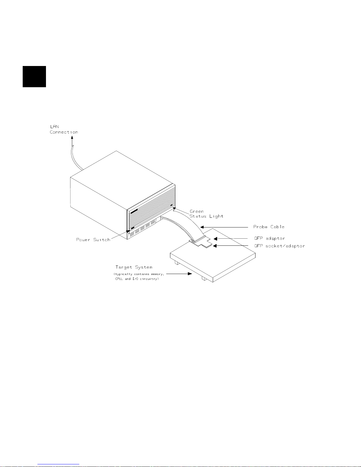
Figure 1-1. HP 64784 Emulato r for the H8/3003
1-2 Introduction to the H8/3003 Emulato r
Page 13

Features of the
H8/3003 Emulator
Supported
Microprocessors
Supported Microproce ssor QFP Adaptor
Type Package System
Clock
Divider
H8/3005 80pinQF P
H8/3004 80pinQFP
H8/3003 112 pin QFP
1:2 -
The HP 64784A H8/300 3 emul a tor suppor ts th e mic ro proc e ssors l ist ed
in Table 1-1.
Table 1-1. Supported Microprocessors
PGA Adaptor
On-chip ROM Supply Voltage
4.75 t o 5. 2 5 V
--
2.7 to 5.25V
4.75 t o 5. 2 5 V
--
2.7 to 5.25V
4.75 t o 5. 2 5 V
2.7 to 5.25V
4.75 t o 5. 2 5 V
--
2.7 to 5.25V
Board
-
-
HP64784C HP64784E/
Board/
QFP probe
HP64784E/
HP64784K*1
HP64784E/
HP64784K*1
HP64784F
H8/3002 100 pin QFP
H8/3001 80 pin QFP
4.75 to 5.25V HP64784D HP64784E/
--
2.7 to 5.25V
4.75 t o 5. 2 5 V
--
HP64784G
HP64784E/
-
Introduction to the H8/3003 Emulator 1-3
HP64784J *1
Page 14

Table 1-1. Supported Microprocessors (Cont’d)
Supported Microproce ssor QFP Adaptor
Type Package System
Clock
Divider
H8/3032 80 pin QFP
H8/3031 80 pin QFP
H8/3030 80 pin QFP
H8/3042 100 pin QFP
On-chip ROM Supply Voltage
2.7 to 5.25V
4.75 to 5.25V
PROM
2.7 to 5.25V
-
4.75 to 5.25 V
Masked ROM
2.7 to 5.25V
4.75 to 5.25 V
--
2.7 to 5.25 V
4.75 to 5.25 V
--
2.7 to 5.25 V
4.75 to 5.25V
PROM
2.7 to 5.25V
-
4.75 to 5.25V
Masked ROM
2.7 to 5.25V
PGA Adaptor
Board
Board/
QFP probe
HP64784E/
-
HP64784H
HP64784E/
-
HP64784H
HP64784E/
-
HP64784H
HP64784D HP64784E/
HP64784G
H8/3041 100 pin QFP
- Masked ROM
H8/3040 100 pin QFP
- Masked ROM
*1 When you do in-ci rc ui t emu lati on fo r H8/3 001 wi th mode 3/4 or
H8/3004/5 with mode 3, you must use HP 647 84-6 6509 shipp ed with
HP 64784J/K. Refe r to the "In-Circ ui t Emula tion" Chapter in this
manual for more details.
1-4 Introduction to the H8/3003 Emulato r
4.75 to 5.25V HP64784D HP64784E/
HP64784G
2.7 to 5. 5V
4.752 to 5.25V HP64784D HP64784E/
HP64784G
2.7 to 5.25V
Page 15

The H8/3003 e mu lato r is provid ed with out any QFP ada pt ors a nd PGA
adaptor(HP 647 84E ) wit h QFP probe. To emulate eac h proce ssor wi th
your target syste m , you need to purch ase appro pri at e QFP adapt or or
PGA adaptor with QFP probe liste d in Tabl e 1-1. To purcha se the m,
contact your l oc al HP sal es re pr esentati ve .
You can buy HP 64797B low voltage adap tor to emula te eac h
processor runni ng with sup ply voltage from 2.7 up to 5.25V inp ut in
your target syste m . To buy HP 64797B, cont act your l ocal HP sales
repres e ntative.
The list of supported micr opro cessor s in Tab le 1-1 i s not nece ssar ily
complete. To determ ine if your m icro proc e ssor i s suppor te d or no t,
contact Hewlett-Packard.
Clock Speeds You can select whethe r t he emul ator wi ll be clo ck ed by the in ternal
clock source or by the external clock sour ce on your targ et syste m.
When you sele c t a cl oc k in put con form i ng to the spe cification of Tabl e
1-2.
Refer to the "Conf igu ra ti on the E mula t or" Cha pt e r in this ma nua l fo r
more de tails.
Introduction to the H8/3003 Emulator 1-5
Page 16

Table 1-2. Clock Speeds
Clock source Chip Without 64797B With 64797B
Internal H8/3001
H8/3002
H8/3003T
H8/3004
H8/3005
H8/3030
H8/3031
H8/3032
H8/3040
H8/3041
H8/3042
H8/3003 with system
cloc k divider
External H8/3001
H8/3002
H8/3003T
H8/3004
H8/3005
H8/3030
H8/3031
H8/3032
H8/3040
H8/3041
H8/3042
16MHz
(System clock)
8MHz
(System clock)
From 0.5 up to 16MHz
(System clock)
8MHz
(System clock)
8MHz
(System clock)
From 0.5 up to 10MHz
(System clock)
H8/3003 with system
cloc k divider
1-6 Introduction to the H8/3003 Emulato r
From 1 up to 24MHz
(System cloc k is from
0.5 up to 12MHz)
From 1 up to 20MHz
(System clock i s from
0.5 up to 10MHz)
Page 17

Emulation memory The H8/3003 emulator is used with one of the following Emulation
Memory Cards.
HP 64726A 128K byte Emula tion Me mo ry Card
HP 64727A 512K byte Emula tion Me mo ry Card
HP 64728A 1M byte Emula t ion Memory Card
HP 64729A 2M byte Emula t ion Memory Card
You can defin e up to 16 me mo ry ranges (at 512 byte bo unda ri e s and
least 512 byt e in le ngt h. ) The em ula t or oc c upi es 6K byte, which is
used for monitor pro gram and interna l RAM of micr o proc e ssor ma ppe d
as emulation RAM, leaving 1 22K, 506K, 1018K, 2042K byte of
emulati on m emo ry which you may use. You can chara c teri z e me mo ry
range as emul atio n RAM (e ra m), em ulat ion ROM (er om ), target
system RAM (tram), tar get system ROM (trom ), or guard ed mem ory
(grd). The emulator gene ra tes an error messa ge when acc esse s are
made to guarde d m emo ry lo ca t ion s. You can al so configure the
emulator so that writes t o memory def ined as ROM cause e mula to r
execu tion to break out of targe t pr ogra m ex ecution.
Analysis The H8/3003 emulator is used with one of the following analyzers
which allows you to trace code exec ut ion an d proce ssor a cti vity.
HP 64704A 80-channel Emulation Bus Ana l yz er
HP 64703A 64-channel Emulation Bus Ana l yz er and
16-ch an nel State/ T im ing Analyzer.
HP 64794A/C/D Deep Emulat ion Bus Ana lyze r
The Emulatio n Bus Analy ze r moni to rs the emu lati on pr ocesso r usin g
an internal analy sis bus. The HP 64703A 64- ch an ne l Emula tion Bu s
Analyzer and 16 -cha nne l Stat e/T imi ng Ana lyze r allows you to probe
up to 16 different lines in your target syst em.
Registers You can displa y or modi fy the H8/30 03 in terna l reg ist er conte nts. This
include s the abili ty t o mo dify the pro gram counter (PC ) va lue so you
can control where the emulator starts a program run.
Breakpoints You can set the emulator/ana lyzer interaction so the emulator will
break to the monit or pr ogra m when the ana lyze r finds a spec ific sta te or
states, allowin g you t o perfor m po st-m or tem anal ysis of the prog ra m
executi on. You can also set softwa re bre a kpo int s in yo ur pro gra m .
This featu re is real ize d by inserting a speci al instru ct io n into use r
Introduction to the H8/3003 Emulator 1-7
Page 18

program. One of un defin ed opc ode s (577 0 hex) is used as soft war e
breakpoint instruc t ion . Refe r to the "Usin g Softwar e Brea kp oin ts"
section of "Getting Started" chapter for more information.
Reset Support The emul at or ca n be reset from the emu lati on syste m unde r your
control; or yo ur targ et syste m can re se t the emulat io n proc essor.
Real Time Operation Real-time signifies con tinuou s exe cut ion of your progr am at ful l rated
processor speed wi thout interf er en ce fro m the emulat or. (Suc h
interfe rence oc curs when the emula to r ne eds to break to the mo nit or t o
perform an action you requeste d, such as displ ay ing targe t system
memory. ) Emul at or fe a tu re s per form e d in real time inc l ude : running
and analyzer tracing. Emulator features not performed in real time
include: displa y or modi fic a tion of targe t syste m me mo ry, load/ dum p
of target m emory, displa y or modi fic a ti on of reg ist er s.
1-8 Introduction to the H8/3003 Emulato r
Page 19

Limitations,
Restrictions
Foreground Monitor Foreground monit or is not support ed for the H8/300 3 emul a tor .
DMA Support Direct memory acce ss to the emul a tion by e xt er na l DMAC is not
allowed.
Internal RAM of
H8/3005
Watch Dog Timer in
Background
Monitor B reak at
Sleep/Standby Mode
Hardware Standby
Mode
Interrupts in
Background Cycles
Reset Output Enable
Bit
When you emulat e H8/300 5 proc e ssor, you can’t use addre ss 0fe f10h 0ff00fh (mode 1) and 0ffe f1 0h - 0ff f00f h (mode 3) as int er na l RAM.
These area are worked as extern al 8bit 3stat e area .
Watch dog time r is suspe nd ed count up while the emul ator i s runni ng
in background monitor.
When the emula to r brea ks int o the bac kgr ound mon itor, sle ep or
software standby mode is released. Then, PC indicates next address of
"SLEEP" instru ctio n.
Hardware standb y mo de is not suppor te d for the H8/3 003 e mula t or.
Hardware sta ndb y reque st fr om targe t syste m will give th e emula tor
reset signal.
The H8/30 03 e mu lato r doe s not ac cep t a ny in terrupts while in
background m oni to r. Such interrupts are suspende d whil e runni ng the
background m oni to r, and will oc cu r when co nte xt is cha nge d to
foreground.
The RSTOE (Reset output enable bit) is used to dete rmi ne whet he r the
H8/3003 processor out put s reset signal when the pro cessor is reset by
the watch dog timer. Howeve r, the H8/ 3003 emulat or ignor es the
configur atio n of th e RSTOE , and works as it is con fig ured with the
modify c onfi gur at io n co mm a nd.
Introduction to the H8/3003 Emulator 1-9
Page 20

Evaluation chip Hewlett-Pa cka rd mak es no warran ty of the problenm cause d by the
H8/3003 Evalua ti on chip in the emulat or.
1-10 Introduction to the H8/3003 Emulato r
Page 21

Getting Started
Introduction This chapt er will lea d you through a basic , step by ste p tutor ia l
designed to familiari z e you with the use of the HP 64700 emula tor for
the H8/3003 micropr oc esso r. When you have compl ete d this chap ter,
you will be able to perform these tasks:
Set up an emulation configuration for out of circuit emulation
use
Map memory
Transfer a small prog ram into emul atio n mem ory
Use run/stop con tro ls to contro l opera t ion of your progr am
Use memory m a nip ula t ion features to a lte r the pro gra m ’s
operat ion
2
Use analyzer comma nds to view the rea l time exe c ution of
your program
Use software breakpoint feature to stop program execution at
speci fic address
Search mem ory fo r strings or num eric expre ssio n s
Make progr am coverage me a surements
Getting Started 2-1
Page 22

Before You Begin Before be gi nni ng t he tut ori al pre se nte d i n thi s ch ap te r, you must have
completed the following tasks:
1. Complete d ha rdwa re in sta lla ti on of t he HP 64700 e m ula tor in
the configu ra ti on you inten d to use for your wor k:
Standalon e configuration
Transparent confi guration
Remote conf igu ra ti on
2. If you are using t he Remot e Confi gur at io n, you must ha ve
completed installation and configuration of a terminal
emulator prog ra m whic h wil l allow your host t o act as a
terminal connecte d t o the emu la to r. In addit ion , yo u mu st sta rt
the termina l em ula tor program bef ore you ca n work the
example s in this c ha pt er .
3. If you have prope rl y c om ple t ed ste ps 1 an d 2 ab ove , you
should be able to hit <RETURN> (or <ENTER> on some
keyboar ds) and ge t on e of the fol lowi ng c om m an d prompt s on
your terminal screen:
U>
R>
M>
If you do not see one of the se c om m an d prom pt s, retrace yo ur
steps throu gh the hardware and softwa re inst a llat ion
proced u re s outl ined in the ma nuals abov e, ve ri fying all
connecti ons a nd pr oc ed ura l step s. If you ar e stil l unabl e to get
a command prompt, refer to the HP 64700 Support Service s
Guide. The guid e give s basic troubl esh ooting proce dure s. If
this fail s, call the lo cal HP sale s a nd se rvice office list e d in the
Support Services Guide.
2-2 Getting Started
In any case, you must have a comm and prompt on your
terminal screen bef ore proc e e din g wit h the tu tor ia l.
Page 23

A Look at the
Sample Program
The sample progra m "COMMAND_READE R" use d in this chapt e r is
shown figure 2-1. The program emulates a primitive command
interpreter.
Data Declarations
Msg_A, Msg_B and Msg_I are the messa ges use d by the progra m to
respond to various c om man d inp uts.
Initializ atio n
The locati ons of st ac k and i nput area (C md _Inp ut) are move d in to
address re gisters for u se by the program. Next, the CLEAR routine
clears the c om mand byte (t he first lo ca tion pointed to by Cmd_In put 0ff800 hex) . Cmd_ Inpu t cont ai ns 00 hex fo r late use.
Scan
This routine conti nuo usly reads t he byte at loca tion of Cmd_Input until
it is something ot he r th an a null cha ra cte r (00 hex); whe n this oc c urs,
the Exe _Cm d routine is executed.
Exe_Cmd
Compare s th e i nput byt e (now something ot her than a null) t o the
possible comman d bytes of "A" (ASCII 41 hex) and "B" (ASCII 42
hex), then jum ps to the approp ria t e set up routine for the command
message. If the input byte does not ma tch either of these values, a
branch to a set up routine for an error message is executed.
Cmd_A, Cmd_B, Cmd_I
These ro uti ne s set up the prope r pa ra m et ers for writing the outp ut
message: the numbe r of byte s in the messa ge is move d to the R3L
register and the base address of th e messag e in the data are a is moved
to address register ER4.
Getting Started 2-3
Page 24

Write_Msg
First the base address of the output area is copied to ER5. Then the
Clear_ Old ro uti ne writes null s to 32 byte s of t he outp ut a re a (thi s
serves bot h to initia liz e the area a nd to clea r old messa ge s wri tt en
during previo us prog ra m passe s).
Finally, the prope r me ssag e is writte n to the out put area by the
Write_Loop routi ne . When do ne , Wri te _L oop jumps bac k to Cle ar and
the comman d mo nitoring process be gi ns a ga in.
Using the various fea tur es of the emula tor , we wil l show you how to
load this p rogram into emulation me mory, exe cute it, monitor the
program ’s ope ra ti on with the anal yz er, and simu late entry of different
command s uti li zing t he mem ory a cce ss c om mand s provi de d by the HP
64700 command set.
2-4 Getting Started
Page 25

002000 1 .SECTION Table,DATA,LOCATE=H’2000
002000 2 Msgs
002000 5448495320495320 3 Msg_A .SDATA "THIS IS MESSAGE A"
002008 4D45535341474520
002010 41
002011 5448495320495320 4 Msg_B .SDATA "THIS IS MESSAGE B"
002019 4D45535341474520
002021 42
002022 494E56414C494420 5 Msg_I .SDATA "INVALID COMMAND"
00202A 434F4D4D414E44
002031 6 End_Msgs
7
001000 8 .SECTION Prog,CODE,LOCATE=H’1000
9 ;****************************************************
10 ;* Set up the Pointers.
11 ;****************************************************
001000 7A07000FF904 12 Init MOV.L #Stack,ER7
001006 7A01000FF800 13 MOV.L #Cmd_Input,ER1
14 ;****************************************************
15 ;* Clear previous command.
16 ;****************************************************
00100C F800 17 Clear MOV.B #H’00,R0L
00100E 6AA8000FF800 18 MOV.B R0L,@Cmd_Input
19 ;****************************************************
20 ;* Read command input byte. If no command has been
21 ;* entered, continue to scan for it.
22 ;****************************************************
001014 6A2A000FF800 23 Scan MOV.B @Cmd_Input,R2L
00101A AA00 24 CMP.B #H’00,R2L
00101C 47F6 25 BEQ Scan
26 ;****************************************************
27 ;* A command has been entered. Check if it is
28 ;* command A, command B, or invalid command.
29 ;****************************************************
00101E AA41 30 Exe_Cmd CMP.B #H’41,R2L
001020 5870000A 31 BEQ Cmd_A
001024 AA42 32 CMP.B #H’42,R2L
001026 58700010 33 BEQ Cmd_B
00102A 58000018 34 BRA Cmd_I
35 ;****************************************************
36 ;* Command A is entered. R3L = the number of bytes
37 ;* in message A. R4 = location of the message.
38 ;* Jump to the routine which writes the message.
39 ;****************************************************
00102E FB11 40 Cmd_A MOV.B #Msg_B-Msg_A,R3L
001030 7A0400002000 41 MOV.L #Msg_A,ER4
001036 58000014 42 BRA Write_Msg
43 ;****************************************************
44 ;* Command B is entered.
45 ;****************************************************
00103A FB11 46 Cmd_B MOV.B #Msg_I-Msg_B,R3L
00103C 7A0400002011 47 MOV.L #Msg_B,ER4
001042 58000008 48 BRA Write_Msg
Figure 2-1. Sample Pro g ram List ing
Getting Started 2-5
Page 26

49 ;****************************************************
50 ;* An invalid command is entered.
51 ;****************************************************
001046 FB0F 52 Cmd_I MOV.B #End_Msgs-Msg_I,R3L
001048 7A0400002022 53 MOV.L #Msg_I,ER4
54 ;****************************************************
55 ;* The destination area is cleared.
56 ;****************************************************
00104E 7A05000FF804 57 Write_Msg MOV.L #Msg_Dest,ER5
001054 FE20 58 Clear_Old MOV.B #H’20,R6L
001056 68D8 59 Clear_Loop MOV.B R0L,@ER5
001058 0B05 60 ADDS.L #1,ER5
00105A 1A0E 61 DEC.B R6L
00105C 46F8 62 BNE Clear_Loop
63 ;****************************************************
64 ;* Message is written to the destination.
65 ;****************************************************
00105E 7A05000FF804 66 MOV.L #Msg_Dest,ER5
001064 6C4E 67 Write_Loop MOV.B @ER4+,R6L
001066 68DE 68 MOV.B R6L,@ER5
001068 0B05 69 ADDS.L #1,ER5
00106A 1A0B 70 DEC.B R3L
00106C 46F6 71 BNE Write_Loop
72 ;****************************************************
73 ;* Go back and scan for next command.
74 ;****************************************************
00106E 409C 75 BRA Clear
76
0FF800 77 .SECTION Data,DATA,LOCATE=H’FF800
78 ;****************************************************
79 ;* Command input area.
80 ;****************************************************
0FF800 00000004 81 Cmd_Input .RES.L 1
82 ;****************************************************
83 ;* Destination of the command messages.
84 ;****************************************************
0FF804 00000100 85 Msg_Dest .RES.W H’80
0FF904 86 Stack
00001000 87 .END Init
2-6 Getting Started
Figure 2-1. Sample Pro g ram List ing (Con t’d)
Page 27

Using the Help
Facility
If you need a quick reference to the Terminal Interface syntax, you can
use the built-i n he lp fac ilit ie s. For exa mp le , to displa y t he top lev el he lp
menu , ty p e:
R> help
help - display help information
help <group> - print help for desired group
help -s <group> - print short help for desired group
help <command> - print help for desired command
help - print this help screen
--- VALID <group> NAMES -- gram - system grammar
proc - processor specific grammar
sys - system commands
emul - emulation commands
hl - highlevel commands (hp internal use only)
trc - analyzer trace commands
* - all command groups
You can type the ? symbol inst e ad of typing help. For exa mp le, if you
want a list of c om m ands in the em ul comm a nd g ro up, type:
R> ? emul
emul - emulation commands
-----------------------------------------------------------------------------
b......break to monitor cp.....copy memory mo.....modes
bc.....break condition dump...dump memory r......run user code
bp.....breakpoints es.....emulation status reg....registers
cf.....configuration io.....input/output rst....reset
cim....copy target image load...load memory rx.....run at CMB execute
cmb....CMB interaction m......memory s......step
cov....coverage map....memory mapper ser....search memory
To display help info rm atio n for any c om m an d, just type help (or ?) an d
the command na me. For exa mple :
R> help load
Getting Started 2-7
Page 28

load - download absolute file into processor memory space
load -i - download intel hex format
load -m - download motorola S-record format
load -t - download extended tek hex format
load -S - download sysmbol file
load -h - download hp format (requires transfer protocol)
load -a - reserved for internal hp use
load -e - write only to emulation memory
load -u - write only to target memory
load -o - data received from the non-command source port
load -s <str> - send a character string out the other port
load -b - data sent in binary (valid with -h option)
load -x - data sent in hex ascii (valid with -h option)
load -q - quiet mode
load -p - record ACK/NAK protocol (valid with -imt options)
load -c <file> - data is received from the 64000. file name format is:
<filename>:<userid>:absolute
Initialize the
Emulator to a
Known State
Note
To initialize the emulator to a known state for this tutorial:
It is especially import a nt tha t you per form the fo llowin g ste p if the
emulato r is be ing operate d i n a stan da lone mode cont rolled by only a
data terminal. The only program entry available in this mode is
through memory modific atio n; conse qu entl y, if the emulat or is
reinit ia li z ed , em ula t ion memory wi ll be clea red and a gre at de al of
tedious wor k could be lost.
1. Verify that no one else is using the emu la to r or will have nee d
of configu ra tion it e ms pr ogra m m ed int o the e mu la to r.
2. Initia li ze th e em ulator by typi ng the comm an d:
R> init
2-8 Getting Started
Page 29

Set Up the Proper
Emulation
Configuration
Set Up Emulation
Conditions
cf ba=en
cf chip=3042
cf clk=int
cf dbc=en
cf drst=dis
cf mode=7
cf nmi=en
cf rrt=dis
cf rsp=9
cf tdma=en
cf trfsh=en
cf trst=en
Note
To set the emula tor’s c onfi gur at io n value s to the proper sta te for t his
tutorial, do this:
1. Type:
R> cf
You should se e the follo wing configuration items displayed:
The individual conf igu ration ite ms wo n ’t be explained in thi s exa m ple;
refer to Chapter 4 of this manual and the User’s Reference manual for
details.
2. If the config ura ti on ite m s displ a ye d on you r scree n do n’t
match the one s liste d a bov e, he re is how to make th em a gre e :
For each con fig ura ti on ite m that does not match, type :
R> cf <config_item>=<value>
Getting Started 2-9
Page 30

cf ba=en
cf chip=3042
cf clk=ext
cf dbc=en
cf drst=dis
cf mode=7
cf nmi=en
cf rrt=en
cf rsp=9
cf tdma=en
cf trfsh=en
cf trst=en
bc -d bp #disable
bc -e rom #enable
bc -d bnct #disable
bc -d cmbt #disable
bc -d trig1 #disable
bc -d trig2 #disable
For example , if you ha ve the fol lowi ng c onf igu ra ti on ite ms
displaye d (those in bold indic ate item s dif fe re nt from the list
above):
To make th ese c onfi gur at io n va lue s a gre e with the desire d
values, type :
R> cf clk=int
R> cf rrt=dis
3. Now, you need to set up stac k poi nte r.
Type:
R> cf rsp=0ff904
4. Let’s go ahe a d and set up th e proper break conditions.
Type:
R> bc
You will see:
For each break con ditio n that does not ma tc h the one list ed ,
use one of the followin g comma nds:
2-10 Getting Started
To enable bre a k conditions that ar e curr en tly disa bl e d, type:
R> bc -e <breakpoint type>
To disable break conditions that are currently enabled, type:
R> bc -d <breakpoint type>
For example , if typi ng bc giv es the foll owi ng li st of bre ak
conditions:
Page 31

bc -d bp #disable
bc -d rom #disable
bc -d bnct #disable
bc -d cmbt #disable
bc -e trig1 #enable
bc -e trig2 #enable
(item s in bol d indica te imp r oper valu es for this ex am pl e )
Type the following commands to set the break condi ti ons
correctl y for this exa mple:
R> bc -e rom
(this enabl es t he writ e to ROM brea k)
R> bc -d trig1 trig2
(this disa bles break on t rig ge rs from the analy ze r)
Mapping Memory Dependi ng on the mem ory bo ar d, emulat io n mem ory consist s of 128K,
512K, 1M o r 2M bytes, map p ab le in 512 byte blocks. Th e m oni to r
occupi es 2K by te s an d the emu la to r maps 4K by te s for i nte rn al RA M
as emulation RAM au toma tic ally , leavi ng 12 2K, 506K, 1018 K or
2042K bytes of emul atio n mem ory which you may use.
The memory m a ppe r all ows you t o char ac t eriz e mem ory loc at io ns. It
allows you specif y whe ther a cert a in rang e of mem ory is pre sen t in the
target system or wheth er you wil l be using emu lati on me mo ry for that
address range . You can also spe cify whe t he r the targ et syste m mem ory
is ROM or RAM, and you can spe cif y that emul at ion me mory be
treated as RAM od ROM.
Type:
R> map 0..0ffff erom
To verif y tha t me m ory bl oc ks a re mapped properly, type:
R> map
Getting Started 2-1 1
Page 32

You will see:
# remaining number of terms : 15
# remaining emulation memory : 6e800h bytes
map 0000000..000ffff erom # term 1
map other tram
Note
Note
Transfer Code
into Emulation
Memory
Transferring Code
from a Terminal In
Standalone
Configuration
You must map inte rna l ROM as emu la tion m e mo ry.
You don’t have to map i ntern al RAM, sinc e the emul ator maps in te rna l
RAM as emulation RAM. And the emu lato r mem ory syste m dose not
introduc e it in mem ory mappi ng di splay.
Refer to "Memory Mapping" section of "Configuring the Emulator"
chapte r in thi s ma nu al for m ore de tai ls.
To transfer code into emulation memory from a data terminal running
in standalone mode, you must use the modify memory commands.
This is necessa ry be c au se yo u have no host compu ter tr an sfe r faci liti es
to automati cal ly downlo ad the co de for you (as i f you would if you
were using the transp ar en t confi gur at io n or the rem ot e conf igu ra tion. )
To minimiz e the effec t s of typ ing errors, you will modify only one row
of memo ry at a time in this example. Do the fol lowi ng:
R> m 002000..00200f=54,48,49,53,20,49,53,20,4d,45,53,53,41,47,45,20
R> m 002010..00201f=41,54,48,49,53,20,49,53,20,4d,45,53,53,41,47,45
2-12 Getting Started
1. Enter the data info rm atio n for the progr am by typi ng th e
following commands:
Page 33

R> m 002020..00202f=20,42,49,4e,56,41,4c,49,44,20,43,4f,4d,4d,41,4e
R> m 002030=44
You could also t ype the fol lo wing line inste a d:
R> m 002000="THIS IS MESSAGE ATHIS IS MESSAGE BINVALID COMMAND"
2. You should now verif y that the da ta area of the progr am is
correct by typing:
R> m 002000..002030
You should see:
002000..00200f 54 48 49 53 20 49 53 20 4d 45 53 53 41 47 45 20
002010..00201f 41 54 48 49 53 20 49 53 20 4d 45 53 53 41 47 45
002020..00202f 20 42 49 4e 56 41 4c 49 44 20 43 4f 4d 4d 41 4e
002030..002030 44
If this is not correc t, yo u can corr ect the er rors by re-en te ring
only the modify m emo ry com ma nd s for th e part icul a r rows of
memory that are wrong.
For example, if row 00200 0..0 0200 f shows these valu es:
002000..00200f 54 48 49 53 20 20 49 53 20 4d 45 53 53 41 47 45
you can correc t this ro w of mem ory by typing :
R> m 002000..00200f=54,48,49,53,20,49,53,20,4d,45,53,53,41,47,45,20
Or, you might ne e d to mod ify only one loca ti on, as i n the
instance wher e address 00200f equals 22 hex rath er than 20
hex. Type:
R> m 00200f=22
3. Enter the progr am inform a ti on by typing t he following
commands:
(Note the hex lette rs mu st be pre c ed ed by a digit.)
R> m 001000..00100f=7a,07,00,0f,0f9,04,7a,01,00,0f, 0f8,00,0f8,00,6a,0a8
R> m 001010..00101f=00,0f,0f8,00,6a,2a,00,0f,0f8,00,0aa,00,47,0f6,0aa,41
R> m 001020..00102f=58,70,00,0a,0aa,42,58,70,00,10,58,00,00,18,0fb,11
R> m 001030..00103f=7a,04,00,00,20,00,58,00,00,14,0fb,11,7a,04,00,00
R> m 001040..00104f=20,11,58,00,00,08,0fb,0f,7a,04,00,00,20,22,7a,05
R> m 001050..00105f=00,0f,0f8,04,0fe,20,68,0d8,0b,05,1a,0e,46,0f8,7a,05
R> m 001060..00106f=00,0f,0f8,04,6c,4e,68,0de,0b,05,1a,0b,46,0f6,40,9c
Getting Started 2-1 3
Page 34

4. You should now verif y that the prog ram are a is corre c t by
typing:
R> m 001000..00106f
You should see:
001000..00100f 7a 07 00 0f f9 04 7a 01 00 0f f8 00 f8 00 6a a8
001010..00101f 00 0f f8 00 6a 2a 00 0f f8 00 aa 00 47 f6 aa 41
001020..00102f 58 70 00 0a aa 42 58 70 00 10 58 00 00 18 fb 11
001030..00103f 7a 04 00 00 20 00 58 00 00 14 fb 11 7a 04 00 00
001040..00104f 20 11 58 00 00 08 fb 0f 7a 04 00 00 20 22 7a 05
001050..00105f 00 0f f8 04 fe 20 68 d8 0b 05 1a 0e 46 f8 7a 05
001060..00106f 00 0f f8 04 6c 4e 68 de 0b 05 1a 0b 46 f6 40 9c
If this is not correc t, yo u can corr ect the er rors by re-en te ring
only the modify m emo ry com ma nd s for th e part icul a r rows of
memory that are wrong.
2-14 Getting Started
Page 35

Transferring Code
From A Host, HP
64700 In Transparent
Configuration
The method pro vided in this exa mp le assu mes th at you are runn ing an
Assembler/ Linka ge Editor on an HP 9000/3 00 com put er running t he
HP-UX operating syste m. In add ition , you must have the HP 64000
transfer soft war e runni ng on your host .
If you are not using a n Assem ble r/L i nka ge Edit or, you m ay be able to
adapt the meth ods be lo w to lo ad your code in to the emulator (ref er to
the HP 6470 0 User’s Referenc e manual for he lp).
If you are not able to transfer code fro m your host to the emulator usi ng
one of these me tho ds, use t he me thod de sc ribed previo usly unde r
"Transfe rri ng Co de From A Term ina l In Sta nda l one Mode ", as it will
work in all cases. However, transf errin g co de using host tra nsfe r
facilit ie s is e asi e r an d fa ste r th an mod ifying memory l ocations,
especia lly for lar ge progr ams.
1. First, you must estab li sh co mmun ic ati ons wit h you r host
computer through t he transpa re nt mode link prov ided i n the
HP 64700. Type:
R> xp -s 02a
This sets the sec ond esc a pe cha ra cte r t o "*".(The first esc a pe
character rema ins at the HP 64700 powe rup defau lt of hex
01b, which is the ASCII <ESC>cha ra cte r.) The sequen ce
"<ESC>*" togg les the tran spa re nt mode softwa re within the
HP 64700 for the dura tion of one comma nd (tha t is, any va li d
line of HP 64700 commands (n ot exce ed 254 cha ract ers)
concate na ted by sem icol ons a nd t er mi nate d by a <carr ia ge
return>). Re fe r to t he User’s Refere nc e manual fo r more
informa ti on on the xp c om ma nd .
login:
login:
login:
Enable the tra nsparent mode l ink by typing :
R> xp -e
If you then press <RE T URN> a few time s, you should see :
This is the login prom pt for an HP- UX host syst em. (Your
prompt may diff er dep ending on how your system manag er
has configure d yo ur syst em. )
Getting Started 2-1 5
Page 36

2. Log in to your host system and sta rt up an edi tor such as "vi".
You should now enter th e sourc e code for the sam ple progr am
shown at the beginnin g of the cha pt er . When fin ishe d, sa ve
the program to file na m e "sam ppr og. src".
Note
If you need help lea rni ng ho w to log in to your HP-UX host syst e m or
use other features of the system, such as editors, refer to the HP-UX
Concepts and Tu tor ials gu ides a nd you r HP-UX system admi nistrator.
3. Assemble and link your code.
4. Convert your absol ute fi le gene ra ted above into HP format
with the followin g co mm and. This is neede d to loa d the file
into the emulator.
$ h83cnvhp -x sampprog
An HP format absolut e file sa mp prog .X will be genera ted .
Now it’s time to transf er your c ode into the emul ator. Do the following:
1. Disable the transp aren t mode so that your ter mina l will talk
direct ly to the emulator. Type:
$ <ESC>* xp -d
The "<ESC>*" seque nc e temp orarily toggl e s the tra nsparent
mode so that the emul a tor will acce pt com m an ds; "xp -d" then
fully disables the transparent mode.
2-16 Getting Started
2. Load code into the emulator by typing:
R> load -hbo
transfer -rtb sampprog.X<ESC>* (NOTE: DO NOT
TYPE CARRIAGE RETURN!)
The system will respond:
##
R>
load -hbo tells th e em ula t or to load code ex pe ct e d in H P
binary fi le form a t and t o ex pect the da ta fro m t he othe r po rt
(the one con ne cte d to the host). It then put s you i n
Page 37

communic ati on wi th the host; you the n ente r the tra nsfe r
command to start the HP 6400 0 tra nsfer utility. Ty ping
"<ESC>* " tell s the syste m to ret urn t o the emu la to r afte r
transfe rri ng th e code . The "##" marks re tu rne d by t he syste m
indicates th at the emu lato r loade d two re co rds fro m the host.
3. At this point you sho uld examin e a port io n of m emo r y to
verify that your cod e was loade d corr ec tly.
Type:
R> m 2000..2030
You should see:
002000..00200f 54 48 49 53 20 49 53 20 4d 45 53 53 41 47 45 20
002010..00201f 41 54 48 49 53 20 49 53 20 4d 45 53 53 41 47 45
002020..00202f 20 42 49 4e 56 41 4c 49 44 20 43 4f 4d 4d 41 4e
002030..002030 44
If your system does not match , verify 1) that you en tered th e
source code correc tly; 2) that you entere d the linker
param et e rs co rre c tl y.
Getting Started 2-1 7
Page 38

Looking at Your
Code
Now that you have lo ad ed your code in to em ula tion memory, you can
display i t in mne m oni c form a t. Typ e:
R> m -dm 1000..106f
You will see:
0001000 - MOV.L #000ff904,ER7
0001006 - MOV.L #000ff800,ER1
000100c - MOV.B #00,R0L
000100e - MOV.B R0L,@0ff800
0001014 - MOV.B @0ff800,R2L
000101a - CMP.B #00,R2L
000101c - BEQ 001014
000101e - CMP.B #41,R2L
0001020 - BEQ 00102e
0001024 - CMP.B #42,R2L
0001026 - BEQ 00103a
000102a - BRA 001046
000102e - MOV.B #11,R3L
0001030 - MOV.L #00002000,ER4
0001036 - BRA 00104e
000103a - MOV.B #11,R3L
000103c - MOV.L #00002011,ER4
0001042 - BRA 00104e
0001046 - MOV.B #0f,R3L
0001048 - MOV.L #00002022,ER4
000104e - MOV.L #000ff804,ER5
0001054 - MOV.B #20,R6L
0001056 - MOV.B R0L,@ER5
0001058 - ADDS #1,ER5
000105a - DEC.B R6L
000105c - BNE 001056
000105e - MOV.L #000ff804,ER5
0001064 - MOV.B @ER4+,R6L
0001066 - MOV.B R6L,@ER5
0001068 - ADDS #1,ER5
000106a - DEC.B R3L
000106c - BNE 001064
000106e - BRA 00100c
2-18 Getting Started
Page 39

Familiarize
Yourself with the
System Prompts
Note
The followi ng ste ps a re not int en ded to be c om plet e expl a na ti ons of
each command; the information is only provided to give you some idea
of the meanings of the various c om m an d prom pt s you m a y see and
reasons why the prompt changes as you exec ute vari ous c omma nd s.
You should gain some fami liar ity wit h the HP 64700 emul a tor
command prom pts by doi ng th e following:
1. Ignore the curre nt command prom pt. Type:
*> rst
You will see:
R>
The rst comman d resets the e mula tion proc esso r and holds it
in the re set state. The "R>" prom pt indicates that the
processor is reset.
2. Type:
R> r 1000
You will see:
U>
The r command run s the proc e ssor fr om addre ss 1000 he x.
3. Type:
U> b
You will see:
M>
The b comm an d cause s th e emula t ion proce ssor to "bre ak "
execution of whatever it was doing and begin executing within
Getting Started 2-1 9
Page 40

the emulation monitor. The "M>" prompt indicates that the
emulator is running in the monitor.
Note
Running the
Sample Program
Note
If DMA transfer is in progress wi th BURST transfe r m ode , b command
is suspended and occurs after DMA transfer is completed.
4. Type:
M> r 1000
The emulator c ha nge s sta t e from backg roun d to fore grou nd
and begins running the sam pl e progr am fro m loc atio n 1000
hex.
The default num be r base for ad dre ss an d data va lues wit hi n HP 64700
is hexade c im a l. Othe r nu mb er base s m ay be spec if ie d. Refer to the
Tutorials chapter of this manual or the HP 64700 User’s Reference
manual for further details.
5. Let’s look at th e regi ste rs t o verif y tha t the addre ss re gist e r s
were prope rl y in it ia liz ed with the pointe rs t o the input and
output areas. Type:
U> reg
You will see:
reg pc=001014 ccr=84 er0=00000000 er1=000ff800 er2=00000000 er3=00000000
reg er4=00000000 er5=00000000 er6=00000000 er7=000ff904 sp=000ff904 mdcr=c7
Notice that ER1 c ont ains 0ff800 hex.
2-20 Getting Started
Page 41

6. Verify tha t the inp ut are a comm a nd byt e was c lea re d duri ng
initializat ion.
Type:
U> m -db 0ff800
You will see:
00ff800..00ff800 00
The input byte location was successfully cleared.
7. Now we will use the emula tor feat ure s to ma ke the progra m
work. Remember tha t the progra m write s speci fic messa ge s to
the output a re a depe nd ing on what the input byte loc at io n
contains. Type:
U> m 0ff800=41
This modi fi es t he inpu t byte loca ti on to the he x va lue for an
ASCII "A". Now let’s check the output are a for a messa ge.
U> m 0ff804..0ff823
You will see:
00ff804..00ff813 54 48 49 53 20 49 53 20 4d 45 53 53 41 47 45 20
00ff814..00ff823 41 00 00 00 00 00 00 00 00 00 00 00 00 00 00 00
These are the ASCII values for Msg_ A.
Repea t the last two commands twice. The fi rst t im e, use 42
instead of 41 at location ff800h and note that Msg_B
overwrites Msg_A. Then try these again, using any numbe r
except 00, 41, or 42 and note that the Msg_I message is
written to this area.
Getting Started 2-2 1
Page 42

Stepping Thro ugh
the Program
8. You can also direct the emu la tor proc e ssor to ex ecut e one
instructio n or numbe r of instruc ti ons. Type :
M> s 1 1000;reg
This comm and ste ps 1 in stru ctio n from addre ss 100 0 he x, and
displays re gisters. You will see:
0001000 - MOV.L #000ff904,ER7
PC =0001006
reg pc=001006 ccr=80 er0=00000000 er1=000ff800 er2=00000000 er3=00000000
reg er4=00000000 er5=00000000 er6=00000000 er7=000ff904 sp=000ff904 mdcr=c7
Notice that PC cont a ins 10 06 hex.
9. To step one instru ctio n from present PC, you only need to type
s at prompt. Typ e:
M> s;reg
You will see:
0001006 - MOV.L #000ff800,ER1
PC =000100c
reg pc=00100c ccr=80 er0=00000000 er1=000ff800 er2=00000000 er3=00000000
reg er4=00000000 er5=00000000 er6=00000000 er7=000ff904 sp=000ff904 mdcr=c7
Trac ing Progr a m
Execution
Predefined Trace
Labels
#### Emulation trace labels
tlb addr 16..39
tlb data 0..15
tlb stat 40..57
2-22 Getting Started
Three trac e label s are pred ef ined i n the H8/3003 emul ator. You ca n
view these labels by entering the tlb (trace label) command with no
options.
M> tlb
Page 43

Predefined Status
Equates
Common va l ues for the H8/ 3 00 3 status tra c e si gna ls have bee n
predefined. You can view these predefined equates by entering the equ
command with no options.
M> equ
### Equates ###
equ bg=0xxx0xxxxxxxxxxxxxxy
equ byte=0xxxxxx1xxxx1xxxx1xy
equ cpu=0xxxxxx1xxxx11xxxxxy
equ data=0xxxxxx1xxxx1x1xxxxy
equ dma=0xxxxxx1xxxx10xxxxxy
equ fetch=0xxxxxx1x1xx110xx01y
equ fg=0xxx1xxxxxxxxxxxxxxy
equ grd=0xxxx011xxxx1xx1xxxy
equ intack=0xxxxxxx0xxxxxxxxxxy
equ io=0xxxxxx1xxxx1xx0xxxy
equ mem=0xxxxxx1xxxx1xx1xxxy
equ read=0xxxxxx1xxxx1xxxxx1y
equ refresh=0xxxxxx1xxxx01xxxxxy
equ word=0xxxxxx1xxxx1xxxx0xy
equ write=0xxxxxx1xxxx1xxxxx0y
equ wrrom=0xxxx101xxxx1xx1xx0y
These equa t es m a y be used to spec ify value s for t he st at trace label
when qualify ing trace condit ion s.
Specifying a Trigger Now let’s use the emula tion a nalyz er to trac e exec ution of the progra m.
Suppose that you would like to start the trace when the ana lyze r begi ns
writing data to the messa ge output area.You can do this by specifying
analyze r trigg er upon e nc oun teri ng th e address ff804 hex.
Furthermore , you mig ht wa nt to store only the data writ ten to the
output area . Th is c an be acco mp li she d by modi fying what is known as
the "ana ly ze r s t ora ge speci fi ca t ion " .
Note
For this exam ple , you wi ll be using the ana lyz er in the ea sy
configur ation, which sim pl if ie s the pro cess of a na ly ze r me asu re me nt
setup. The co mp lex configuration al lows mo r e power ful mea sure m en ts,
but requires more interaction from you to set up those measurements.
For more inform a ti on on easy a nd com ple x ana ly ze r conf igurations and
the analyzer, refer to the HP 64700 Analyzer Use r’s Guide and the
User’s Refere nce .
Getting Started 2-2 3
Page 44

Emulation trace started
Now, let’s set the trigger spe cification. Type:
M> tg addr=0ff804
To store only the accesse s to the addre ss ra nge ff80 4 through ff815 hex,
type:
M> tsto addr=0ff804..0ff815
Let’s cha nge the data format of the tr ac e display so that you will see the
output messa ge writ e s displ aye d in ASCII form at:
M> tf addr,h data,A count,R seq
Start the trace by typing:
M> t
You will see:
To start the emulation run, type:
M> r 1000
Now, you need to hav e a "comm and" i nput to the program so that the
program wi ll jump to the output routines (o therwise the trigger will not
be found, since the prog ra m will never access a ddr ess ff 804 he x) . Type :
U> m 0ff800=41
2-24 Getting Started
To display the trace list, type :
U> tl 0..34
You will see:
Page 45

Line addr,H data,A count,R seq
----- ------ ------ --------- -- 0 0ff804 .. --- +
1 0ff805 .. 0.760 uS .
2 0ff806 .. 0.720 uS .
3 0ff807 .. 0.760 uS .
4 0ff808 .. 0.760 uS .
5 0ff809 .. 0.760 uS .
6 0ff80a .. 0.720 uS .
7 0ff80b .. 0.760 uS .
8 0ff80c .. 0.760 uS .
9 0ff80d .. 0.760 uS .
10 0ff80e .. 0.720 uS .
11 0ff80f .. 0.760 uS .
12 0ff810 .. 0.760 uS .
13 0ff811 .. 0.760 uS .
14 0ff812 .. 0.720 uS .
15 0ff813 .. 0.760 uS .
16 0ff814 .. 0.760 uS .
17 0ff815 .. 0.760 uS .
18 0ff804 TT 12.00 uS .
19 0ff805 HH 1.120 uS .
20 0ff806 II 1.120 uS .
21 0ff807 SS 1.120 uS .
22 0ff808 .. 1.120 uS .
23 0ff809 II 1.120 uS .
24 0ff80a SS 1.120 uS .
25 0ff80b .. 1.120 uS .
26 0ff80c MM 1.160 uS .
27 0ff80d EE 1.120 uS .
28 0ff80e SS 1.120 uS .
29 0ff80f SS 1.120 uS .
30 0ff810 AA 1.120 uS .
31 0ff811 GG 1.120 uS .
32 0ff812 EE 1.120 uS .
33 0ff813 .. 1.120 uS .
34
Emulation trace halted
If you loo k at the la st lin es o f the tra c e list ing, you wil l no ti ce th at the
analyz e r se ems to have store d onl y pa rt of the output message, even
though you specifie d more than the full range needed to stor e all of the
message. The re ason for this is that the analyzer ha s a storage pipeline ,
which holds states that have been acquired but not yet written to trace
memory. To see all of the states, halt the analyzer by typing:
U> th
You will see:
Now display the trace list:
U> tl 0..34
You will see:
Getting Started 2-2 5
Page 46

Line addr,H data,A count,R seq
----- ------ ------ --------- -- 0 0ff804 .. --- +
1 0ff805 .. 0.760 uS .
2 0ff806 .. 0.720 uS .
3 0ff807 .. 0.760 uS .
4 0ff808 .. 0.760 uS .
5 0ff809 .. 0.760 uS .
6 0ff80a .. 0.720 uS .
7 0ff80b .. 0.760 uS .
8 0ff80c .. 0.760 uS .
9 0ff80d .. 0.760 uS .
10 0ff80e .. 0.720 uS .
11 0ff80f .. 0.760 uS .
12 0ff810 .. 0.760 uS .
13 0ff811 .. 0.760 uS .
14 0ff812 .. 0.720 uS .
15 0ff813 .. 0.760 uS .
16 0ff814 .. 0.760 uS .
17 0ff815 .. 0.760 uS .
18 0ff804 TT 12.00 uS .
19 0ff805 HH 1.120 uS .
20 0ff806 II 1.120 uS .
21 0ff807 SS 1.120 uS .
22 0ff808 .. 1.120 uS .
23 0ff809 II 1.120 uS .
24 0ff80a SS 1.120 uS .
25 0ff80b .. 1.120 uS .
26 0ff80c MM 1.160 uS .
27 0ff80d EE 1.120 uS .
28 0ff80e SS 1.120 uS .
29 0ff80f SS 1.120 uS .
30 0ff810 AA 1.120 uS .
31 0ff811 GG 1.120 uS .
32 0ff812 EE 1.120 uS .
33 0ff813 .. 1.120 uS .
34 0ff814 AA 1.160 uS .
2-26 Getting Started
As you can see, all of the requested stat e s hav e bee n c ap tur ed by the
analyzer.
Page 47

Using Software
Breakpoints
You can stop program exe cu tion at spec ific addre ss by using bp
(software brea kpoi nt ) co mm and. W he n you defi ne a softwa re
breakpoint to a certa in addr ess, th e emula t or wil l repl a ce the op co de
with one of unde fin ed opc ode (577 0 hex) a s softwa re bre a kpo int
instruction. When the emul ator det ect s the spe cia l instruct ion, user
program bre ak s to th e moni tor, and the ori gin al opc ode wil l be plac e d
at the breakp oin t addre ss. A subse que nt run or step comm a nd wil l
execute from this address.
If the speci al instruction was not inse rt e d as the result of bp command
(in other words, it is part of the user prog ra m) , the "Unde fin ed softwa re
breakpo int " me ssage is displayed.
Note
Note
Displaying and
Modifying the Break
Conditions
bc -d bp #disable
bc -e rom #enable
bc -d bnct #disable
bc -d cmbt #disable
You can set softwar e br eakp oin ts onl y at mem or y loca ti ons whi ch
contain in stru ctio n opc ode s (no t ope ra nd s or da ta). If a softwa re
breakpo int is se t at a mem ory l oc atio n whic h is n ot an instru ct io n
opcode, th e sof tware brea kpoi nt inst ruc tion will never be exec ute d a nd
the break will never occur.
Becau se software brea kpoi nts are impl e mented by repl ac i ng opc od es
with the sof twa re bre akpoint instruc ti on, you canno t de fi ne software
breakpoint s in targe t ROM. You c an, however, copy target ROM into
emulati on m e mory by cim command. (Refer to HP 64 700 Te rminal
Interface User’s Refere nce manual.)
Before you can defi ne soft war e breakpoints, you m ust enabl e software
breakpo int s wit h the bc (bre a k conditions) comm an d. To vie w the
default bre ak c ondi ti ons and c ha nge th e softwa re bre a kpoi nt condit io n,
enter the following commands.
M> bc
Getting Started 2-2 7
Page 48

bc -d trig1 #disable
bc -d trig2 #disable
M> bc -e bp
Defining a Software
Breakpoint
Now that the software break poi nt is enabl e d, you can define softwa re
breakpoint s. Ente r the fol lo wing comm and to bre ak on the addre ss of
the Write_Msg label .
M> bp 104e
Run the program and verify tha t execu tion bro ke at the appropria te
address.
M> r 1000
U> m 0ff800=41
!ASYNC_STAT 615! Software break point: 000104e
M> reg
reg pc=00104e ccr=80 er0=00000000 er1=000ff800 er2=00000041 er3=00000011
reg er4=00002000 er5=00000000 er6=00000000 er7=000ff904 sp=000ff904 mdcr=c7
Notice that PC cont a ins 10 4e.
When a breakp oin t is hit, it beco me s di sab le d. You c an use the -e
option to the bp comma nd t o re -e na ble th e software brea kpoint.
M> bp
###BREAKPOINT FEATURE IS ENABLED###
bp 000104e #disabled
M> bp -e 104e
M> bp
###BREAKPOINT FEATURE IS ENABLED###
bp 000104e #enabled
M> r 1000
U> m 0ff800=41
!ASYNC_STAT 615! Software breakpoint: 000104e
M> bp
###BREAKPOINT FEATURE IS ENABLED###
bp 000104e #disabled
2-28 Getting Started
Page 49

Searching
Memory for
Strings or
Numeric
The HP 64700 E mulator provides you with too ls that allow you to
search mem ory fo r da ta stri ngs or numer ic expre ssio ns. For ex ampl e ,
you might want to know exactly where a string is loaded. To locate the
position of the stri ng "T HIS IS ME SSAGE A" in the sam pl e progr am .
Type:
Expressions
pattern match at address: 0002000
You can also find num e ri c expr essi ons. For exa m ple, you mig ht want
to find all of the CMP.B instruc tions in the sample pro gra m . Sinc e a
CMP.B instruc ti on be gi ns wit h aa he x, you c a n searc h fo r that value by
typing:
pattern match at address: 000101a
pattern match at address: 000101e
pattern match at address: 0001024
M> ser 2000..2fff="THIS IS MESSAGE A"
M> ser -db 10000..106f=0aa
Making Program
Coverage
Measurements
In testing your progr am, you will often wa nt to verify th at all possibl e
code segments are executed. Wit h the sample program, we might want
to verify tha t all of the code is e xe c ute d if a com m an d "A", com m an d
"B", and an unrec ogni z ed comma nd a re input to the prog ra m.
To make th is m ea surement , we mu st fi rst re set the cover age status.
M> cov -r
Getting Started 2-2 9
Page 50

Note
percentage of memory accessed: % 100.0
You should alway s reset the coverage status before making a coverage
measurement . Any emul ator syste m comm an d which ac cesse s
emulati on m emo ry will affect the cov er ag e st atus bi t, resulting in
measur eme nt errors if the cove ra ge sta tus is n ot rese t.
Now, run the program and input the thr ee command s:
M> r 1000
M> m 0ff800=41
M> m 0ff800=42
M> m 0ff800=43
Make the coverage measurement:
U> cov 1000..106f
Trace Analysis
Considerations
How to Specify the
Trigger Condition
2-30 Getting Started
There are some poin ts you need to atte nd to in using the emula ti on
analyze r. Th e foll owin g sec t ion desc ri be s suc h poi nts.
Suppose that you would like to start the trace whe n the progra m begins
executing Exe_Cmd routine.
To initi a li ze th e e m ula t ion ana l yzer, type :
U> tinit
To set the tr igger con dit io n, type:
U> tg addr=101e
Start the trace and mo dif y mem ory so that the progr am wil l jum p to the
Exe_Cmd rou tine :
U> t
U> m 0ff800=41
To display the trace list, type :
Page 51

U> tl 0..20
Line addr,H H8/3042 mnemonic,H count,R seq
----- ------ ----------------------------------- --------- -- 0 00101e aa41 fetch mem --- +
1 001014 MOV.B @0ff800,R2L 0.120 uS .
2 001016 000f fetch mem 0.120 uS .
3 001018 f800 fetch mem 0.120 uS .
4 00101a CMP.B #00,R2L 0.120 uS .
5 0ff800 00xx read mem byte 0.120 uS .
6 00101c BEQ 001014 0.120 uS .
7 00101e aa41 fetch mem 0.160 uS .
8 001014 MOV.B @0ff800,R2L 0.120 uS .
9 001016 000f fetch mem 0.120 uS .
10 001018 f800 fetch mem 0.120 uS .
11 00101a CMP.B #00,R2L 0.120 uS .
12 0ff800 00xx read mem byte 0.120 uS .
13 00101c BEQ 001014 0.120 uS .
14 00101e aa41 fetch mem 0.120 uS .
15 001014 MOV.B @0ff800,R2L 0.160 uS .
16 001016 000f fetch mem 0.120 uS .
17 001018 f800 fetch mem 0.120 uS .
18 00101a CMP.B #00,R2L 0.120 uS .
19 0ff800 00xx read mem byte 0.120 uS .
20 00101c BEQ 001014 0.120 uS .
This is not what we we re exp ect ing to se e. (W e expec t ed to see the
program executed Exe_Cmd routine which starts from 101e hex.) As
you can see at the fist line of the trace list, address 101e hex appears on
the address bu s duri ng th e program execut in g Sca n loop. This t rig ge re d
the emulation ana l yzer before EXE_C md rout ine was exe c ut ed . T o
avoid mis-trigg er by this cause , set the trigg er condit io n to the sec ond
instructio n of the ro utine you wa nt to trace. Type:
U> tg addr=1020
To chan ge the tri gge r p o sit ion so that 10 sta te s ap pe ar before the trigger
in the trace list, ty p e:
U> tp -b 10
Start the tr ac e ag ai n a nd m odi fy m em ory:
U> t
U> m 0ff800=41
Now display the trace list:
U> tl -10..10
As you can see, the ana lyz e r c ap tur ed the execut ion of Exe_Cm d
routine which sta rts from line -2 of the trac e list.
Getting Started 2-3 1
Page 52

Line addr,H H8/3042 mnemonic,H count,R seq
----- ------ ----------------------------------- --------- ---
-10 00101c BEQ 001014 0.120 uS .
-9 00101e aa41 fetch mem 0.120 uS .
-8 001014 MOV.B @0ff800,R2L 0.120 uS .
-7 001016 000f fetch mem 0.120 uS .
-6 001018 f800 fetch mem 0.120 uS .
-5 00101a CMP.B #00,R2L 0.160 uS .
-4 0ff800 41xx read mem byte 0.120 uS .
-3 00101c BEQ 001014 0.120 uS .
-2 00101e CMP.B #41,R2L 0.120 uS .
-1 001014 6a2a unused fetch mem 0.120 uS .
0 001020 BEQ 00102e 0.120 uS +
1 001022 000a fetch mem 0.120 uS .
2 00102e MOV.B #11,R3L 0.280 uS .
3 001030 MOV.L #00002000,ER4 0.120 uS .
4 001032 0000 fetch mem 0.120 uS .
5 001034 2000 fetch mem 0.120 uS .
6 001036 BRA 00104e 0.120 uS .
7 001038 0014 fetch mem 0.120 uS .
8 00104e MOV.L #000ff804,ER5 0.240 uS .
9 001050 000f fetch mem 0.160 uS .
10 001052 f804 fetch mem 0.120 uS .
Store Condition and
Disassembling
When you specif y stor e cond it ion with tsto comm and, disassem bling of
program exec ut ion ma y not be acc ura te .
Type:
U> tinit
U> t
U> tl 0..20
2-32 Getting Started
Page 53

Line addr,H H8/3042 mnemonic,H count,R seq
----- ------ ----------------------------------- --------- -- 0 001016 000f fetch mem --- +
1 001018 f800 fetch mem 0.120 uS .
2 00101a CMP.B #00,R2L 0.160 uS .
3 0ff800 00xx read mem byte 0.120 uS .
4 00101c BEQ 001014 0.120 uS .
5 00101e aa41 fetch mem 0.120 uS .
6 001014 MOV.B @0ff800,R2L 0.120 uS .
7 001016 000f fetch mem 0.120 uS .
8 001018 f800 fetch mem 0.120 uS .
9 00101a CMP.B #00,R2L 0.120 uS .
10 0ff800 00xx read mem byte 0.160 uS .
11 00101c BEQ 001014 0.120 uS .
12 00101e aa41 fetch mem 0.120 uS .
13 001014 MOV.B @0ff800,R2L 0.120 uS .
14 001016 000f fetch mem 0.120 uS .
15 001018 f800 fetch mem 0.120 uS .
16 00101a CMP.B #00,R2L 0.120 uS .
17 0ff800 00xx read mem byte 0.120 uS .
18 00101c BEQ 001014 0.160 uS .
19 00101e aa41 fetch mem 0.120 uS .
20 001014 MOV.B @0ff800,R2L 0.120 uS .
The program is exe cuti ng Sca n loo p.
Now, specify t he store c ondi tion so t ha t only a cce sse s to the addr ess
range 1000 hex thr ough 10ff he x will be store d:
U> tsto addr=1000..10ff
Start the tr ac e and display the trace list:
U> t
U> tl 0..20
Line addr,H H8/3042 mnemonic,H count,R seq
----- ------ ----------------------------------- --------- -- 0 00101c BEQ 001014 --- +
1 00101e aa41 fetch mem 0.120 uS .
2 001014 MOV.B @0ff800,R2L 0.120 uS .
3 001016 000f fetch mem 0.120 uS .
4 001018 f800 fetch mem 0.120 uS .
5 00101a aa00 fetch mem 0.120 uS .
6 00101c BEQ 001014 0.280 uS .
7 00101e aa41 fetch mem 0.120 uS .
8 001014 MOV.B @0ff800,R2L 0.120 uS .
9 001016 000f fetch mem 0.120 uS .
10 001018 f800 fetch mem 0.120 uS .
11 00101a aa00 fetch mem 0.120 uS .
12 00101c BEQ 001014 0.240 uS .
13 00101e aa41 fetch mem 0.120 uS .
14 001014 MOV.B @0ff800,R2L 0.160 uS .
15 001016 000f fetch mem 0.120 uS .
16 001018 f800 fetch mem 0.120 uS .
17 00101a aa00 fetch mem 0.120 uS .
18 00101c BEQ 001014 0.240 uS .
19 00101e aa41 fetch mem 0.120 uS .
20 001014 MOV.B @0ff800,R2L 0.160 uS .
Getting Started 2-3 3
Page 54

As you can see, the e xecu ti ons of CMP. B instr uc ti on a re not
disassembl ed. Thi s occur s when the anal yze r cann ot get nece ssa ry
informa ti on fo r disa ss e m bli ng be c a use of the sto re con dit io n. Be
careful when you use the stor e cond ition .
Triggering the
Analyzer by Data
You may want to trigge r the em ula tion analyzer when spec i fic da ta
appears on th e dat a bus. You can acc om pl ish t his wi th the followi ng
command.
U> tg data=<data>
There are some points to be noticed when you trigger the analyzer in
this way. You always need to specify the <data> with 16 bits value
even when acc e ss to th e dat a is per form e d by by te acc e ss. This i s
because the anal yz er is design ed so that it can capture data on interna l
data bus (which has 16 bits width) . The following tabl e shows the way
to speci fy the trigge r condition by data.
================================================================
Location of | Access | Address | Available
data | size | value | <data> Specification
================================================================
| | even | ddxx *1
8 bit data | byte/word|----------+------------------------ bus area | | odd | xxdd *1
----------------+---------------------+------------------------ | | even | ddxx *1
| byte |----------+------------------------ 16 bit data | | odd | xxdd *1
bus area |----------+----------+------------------------ | word | even | hhll *2
================================================================
*1 dd means 8 bits data
*2 hhll means 16 bits data
2-34 Getting Started
For example, to trig ger the ana lyze r when the pr ocesso r performs word
access to data 1234 he x in 16 bit bus are a, you can spe c ify the
following :
U> tg data=1234
To trigger the anal yzer when the proc e ssor ac ce sse s da ta 12 hex to the
even address loc ate d in 8 bit data bus are a:
U> tg data=12xx
Page 55

On the other hand, to tri gge r 12 hex to the od d add ress loca te d 8 bit
data bus.
U> tg data=0xx12
Notice that you always need to specify "xx" value to capture byte
access to 8 bit data bus area. Be careful to trigger the analyzer by data.
You’re now finishe d wi th the "Get ting Sta rt e d" ex ampl e . You can
procee d on with using t he emulat or a nd use this man ual and the
Terminal Inte rfac e Reference manual as neede d to answer yo ur
question s.
Getting Started 2-3 5
Page 56

Notes
2-36 Getting Started
Page 57

In-Circ uit Emulat ion
When you are re ad y to use th e H8/3003 emulator in conjuncti on wi th
actual targe t system hardware, the re a re some special c onsiderations
you should ke ep in mind .
We will cover the first topic in this chapter. For complete details on
in-circuit em ula tion con fig ura tion, refer to Cha pte r 4.
3
installin g the emu la tor prob e
properly configure the emu lator
3-1 In-Circuit Emulati on
Page 58

Installing the
Target System
Probe
Caution
The following precautions sho uld be tak en while usi ng the H8/30 03
emula to r. Damage to the emulator circuitr y ma y re s ul t i f the se
precauti ons a re not obse rve d.
Power Down Target Syste m. Turn off power to the user target syste m
and to the H8/3003 e m ulat or be for e att a ch ing and deta ching the QFP
adaptor to the emulator or target syste m to avoid circuit dama ge
resulting from vo ltag e transients or mis-inse rt ion of the QFP board.
Verify User Plug Ori ent ation. Make certain that Pin 1 of the QFP
socket/a da pto r and Pin 1 of the QFP ada pt or a re prop er ly aligned
before inserting the QFP adapt or the QFP socke t/a da ptor. Failur e to do
so may result in damage to the emulator circuitry.
Protect Against Static Discharge. The H8/3003 emulator and the QFP
adaptor co ntai n devic e s whic h are suscep ti ble to dama ge by stat ic
discharge . There for e, ope ra tors shou ld tak e prec aut ion ar y mea sure s
befor e ha nd li ng the user pl ug t o av oid em ul at or damage .
Compatibility of VOLTAGE/CURRENCY. Please be sure to check
that the voltage/curre ncy of the emulat or and targe t system bein g
connecte d are co mpat ib le . If there is a disc re pa nc y, dam ag e ma y result .
Protect Targe t System CM O S Compone nts. If your target syste m
includes any CMOS c omponents, turn on the targ et syste m fir st, then
turn on the H8/30 03 e mu la to r; when po wer ing down, tur n off the
emulato r fir st, then turn off power to the targe t syste m .
3-2 In-Circuit Emulatio n
Page 59

The H8/3003 e mu lato r is provid ed with out any QFP ada pt or or PGA
adaptor wit h QFP probe. To emul ate eac h proce ssor wi th your targ et
system, you need to purcha se app ropr iate QFP ad ap tor or PGA adaptor
with QFP probe.
QFP adaptor To emulate each processor with your targe t system , you nee d to
purchase a ppropriate adaptor listed in Table 1-1. The QFP adapto r
allows you to conne c t the em ulat ion probe to your tar ge t system usi ng
the QFP socket/ada ptor prov ided wi th the QFP adapt or.
PGA adaptor To emul ate each proce ssor with your tar get syst em, you ne ed to use HP
64784E PGA adaptor as shown i n Figure 3-2. The PGA adaptor allows
you to connect the emulat ion prob e to QFP socket/a dapt e r on your
target system through the QFP probe listed i n Ta bl e 1-1.
Caution
Caution
Do not apply strong force to QFP probe, as that mi ght dam a ge the
QFP probe.
To emulate H8/3 001 pr ocessor with mode 3/4 or H8/30 04/ 05 proce ssor
with mode 3, you m ust use HP 64784-66509 board as sho wn in Figure
3-3 and 3-4. Connecting the emulator and your target system without
this board causes serious damage, when you emulate in these cases.
Always detach HP 6478 4-66 509 exc e pt you emula te H8/300 1
processor wi th mode 3/4 or H8/300 4/5 with mo de 3.
3-3 In-Circuit Emulati on
Page 60

QFP socket/adaptor The QFP socket/adaptor is provi de d with the QFP adaptor and QFP
probe, and designe d for H8/ 300 3 microprocessor. To do in-ci rc uit
emulation, you must attach th e QFP socket/ ada pto r to your target
system and connec t with the QFP ada ptor or PGA ada pto r.
Note
You can order addi ti ona l QFP socke t /a dapt or with part No. HP
64784-61611 (for H8/30 03), HP 6478 4-61 612( for H8/ 300 2/4 x), HP
64784-61613 (for H8/30 04/ 05/ 3x) or HP 64784- 6161 4(fo r H8/3 001) .
3-4 In-Circuit Emulatio n
Page 61

Installing the QFP
Adaptor 1. Attach the QFP socket/adaptor to your target system.
2. Connect the QFP adaptor to the emula t ion probe.
3. Install the QFP adaptor to the QFP socke t/ad ap tor on your
target system as shown in Fi gure 3-1.
Figure 3-1. Install ing the QFP adapt or
3-5 In-Circuit Emulati on
Page 62

Installing the 64784E
PGA adaptor 1. Attach the QFP socket/adaptor to your target system.
2. Connect the 64784E PGA adaptor to the emula ti on probe.
3. Install the 64784E PGA adapt or to the QFP socket /ada ptor on
your target syste m through QFP pro be (or QFP pro be and HP
64784-66509 ) as sho wn in Figure 3-2 ,3-3 a nd 3-4 .
Figure 3-2 Installing the PGA adap to r (General )
3-6 In-Circuit Emulatio n
Page 63

Figure 3-3 Installing the PGA adap to r (3001 mode 3/4)
3-7 In-Circuit Emulati on
Page 64

Figure 3-4 Installing the PGA adap tor (3004/5 mode 3)
3-8 In-Circuit Emulatio n
Page 65

Installing the H8/3003
microprocessor
Figure 3-5 Installing the H8/3003 micropro cesso r
You can replace the QFP/PGA ada pto r with H8/3 003 m icro proc e ssor.
Refer to the Figure 3-5.
3-9 In-Circuit Emulati on
Page 66

Using Low
Volt age Adap tor
Specification You must conform input high volta ge (Vih ) to the speci fica ti on of Tabl e
Table 3-1. DC Characteristi cs of input high voltag e
Item Minimum (V )
P1 - P5, D0 - D15 Vcc x 0.7
Others Vcc x 0.7
You can use optiona l low volta ge a da pto r with the H8/ 3003 emul at or.
The low voltage adaptor gives you a feature to emulate your target
system runnin g with suppl y volta ge from 2.7V up to 5.25V.
3-1, when you use the low volt ag e ada pt or wit h th e H8/3003 emulator .
or
2.4 *1
or
2.0 *1
*1 Higher of th e t wo.
Note
Note
3-10 In-Circuit Emulatio n
This is differ en t from the targe t proc esso r’s specificat ion.
You must also use a clock conf orm in g to the spec i fica ti on of Tabl e 4-1,
when you use the low vol ta ge a da pto r an d co nfi gure th e em ulator to
use external clock.
Page 67

Installing the 64797B
PGA adaptor 1. Attach the QFP socket/adaptor to your target system.
2. Connect the 64797B PGA a dapto r to the emulat ion prob e.
3. Install the 64797B PGA adaptor to the QFP socket/a da ptor on
your target syste m through QFP pro be (or QFP pro be and HP
64784-66509 ) as shown in Fi gure 3-6.
Figure 3-6 Installing the PGA adap to r (General )
3-11 In-Circuit Emulation
Page 68

Note
You have to use HP 64784-66509 when you emulate H8/3001 with
mode 3/4 or H8/3 004/ 05 wi th mode 3.
Run from Target
System Reset
Note
You can use "r rst" command to execute progr am from tar ge t system
reset. You will see T> syste m prom pt when you ente r "r rst". In this
status, the emulator accept targ et system reset. Then program start s i f
reset signal from tar get system is release d.
In the "Awaiting targ et reset " sta tu s(T >) , you can no t brea k into the
monitor . If you e nte r "r rst " in ou t-o f-circu it or in the con fig uration tha t
emulator doe s not acc ep t targ et syste m reset (cf trst=di s), you must
rese t th e em ula t or.
3-12 In-Circuit Emulatio n
Page 69

Electrical
Characteristics
The AC charac teri sti c s of the HP 6478 4 H8/3 003 em ula tor a re liste d in
the following table.
Table 3-2. Bus timing (Vcc = 5.0V, f = 16MHz)
Characteristi cs Symbol
Clock cycle time
Clock pulse low width
Clock pulse high width
Clock rise time
Clock fa ll time
Address delay time
Address hold time
Address strobe delay time
Write strobe del a y time
t
cyc
t
CL
t
CH
t
CR
t
CF
t
AD
t
AH
t
ASD
t
WSD
H8/3003
Vcc = 5V
f = 16MH z
HP 64784E
Probe Type
+
HP 64784D
Unit
HP 64784x
min max typ *1 worst typ *1 worst
62.5 500 - - - - ns
20 - 23.2 12.9 23.8 13.3 ns
20 - 28.3 12.9 28.3 13.3 ns
- 10 5.6 17.1 5.0 16.7 ns
- 10 5.4 17.1 5.4 16.7 ns
- 30 24.0 33.5 23.6 32.0 ns
10 - 41.0 -4.8 41.2 -5.2 ns
- 30 7.4 35.8 6.6 34.7 ns
- 30 10.0 35.8 9.6 34.7 ns
Strobe delay time
Write data strobe pulse wid th 1
Write data strobe pulse wid th 2
t
SD
t
WSW1
t
WSW2
- 30 2.8 35.8 3.0 34.7 ns
35 - 53.0 28.6 53.8 29.1 ns
65 - 83.0 58.6 83.8 59.1 ns
3-13 In-Circuit Emulation
Page 70

Table 3-2. Bus timing (Vcc = 5.0V, f = 16MHz) (Cont’d)
Characterist ics Symbol
Address setup time 1
Address setup time 2
Read data setup time
Read da ta hol d ti m e
Write data delay time
Write data setup time 1
Write data setup time 2
Write data hold time
Read da ta a cc e ss time 1
t
AS1
t
AS2
t
RDS
t
RDH
t
WDD
t
WDS1
t
WDS2
t
WDH
t
ACC1
H8/3003
Vcc = 5V
f = 16MHz
HP 64784E
Probe Type
HP 64784D
+
HP 64784x
min max typ *1 worst typ *1 worst
10 - 9.8 -24.1 10.6 -23.2 ns
40 - 41.4 5.9 42.2 6.8 ns
20 - 30.4 49.7 24.0 47.3 ns
0 - -27.0 29.7 -20.6 33.3 ns
- 60 29.0 68.7 29.8 69.9 ns
35 - 31.0 -4.8 30.0 -6.6 ns
5 - 3.2 -36.0 2.4 -37.8 ns
20 - 47.2 4.4 47.6 5.8 ns
- 55 42.4 21.3 51.2 24.8 ns
Unit
Read da ta a cc e ss time 2
Read da ta a cc e ss time 3
Read da ta a cc e ss time 4
Pre-charg e time
3-14 In-Circuit Emulatio n
t
ACC2
t
ACC3
t
ACC4
t
PCH
- 115 104.0 83.8 112.8 87.2 ns
- 25 25.8 -12.3 33.4 -9.2 ns
- 85 87.2 50.2 94.8 53.3 ns
35 - 62.8 28.6 62.8 29.1 ns
Page 71

Table 3-2. Bus timing (Vcc = 5.0V, f = 16MHz) (Cont’d)
Characterist ics Symbol
WAIT setup tim e
WAIT set hold time
BREQ setup time
BACK delay time 1
BACK delay time 2
Bus floating time
H8/3003
Vcc = 5V
f = 16MHz
HP 64784E
Probe Type
+
HP 64784x
min max typ *1 worst typ *1 worst
t
WTS
t
WTH
t
BRQS
t
BACD1
t
BACD2
t
BZD
25 - 26.2 60.9 22.6 54.7 ns
5 - -23.6 -11.0 -20.0 -6.1 ns
40 - - 75.9 - 69 .7 ns
- 30 10.4 35.8 10.0 34.7 ns
- 30 -4.2 35.8 -4.0 34.7 ns
- 40 19.0 46.2 20.4 44.7 ns
*1 Typical output s me a sure d wit h 50pF loa d
HP 64784D
Unit
3-15 In-Circuit Emulation
Page 72

Table 3-3. Refresh contro ller timi ng (Vcc = 5.0V, f = 16MHz)
Characterist ics Symbol
RAS delay time 1
RAS delay time 2
RAS delay time 3
Row address hold time
RAS pre-ch arge tim e
CAS to RAS pre-charge time
CAS pulse width
RAS access time
Address access time
t
RAD1
t
RAD2
t
RAD3
t
RAH
t
RP
t
CRP
t
CAS
t
RAC
t
AA
H8/3003
Vcc = 5V
f = 16MHz
HP 64784E
Probe Type
HP 64784D
+
HP 64784x
min max typ *1 worst typ *1 worst
- 30 23.6 41.6 17.8 39.0 ns
- 30 22.2 41.6 16.2 39.0 ns
- 30 8.0 41.6 6.6 39.0 ns
15 - 22.0 -10.5 27.0 -9.5 ns
35 - 60.8 25.8 61.4 26.7 ns
35 - 61.4 28.6 60.2 29.1 ns
40 - 52.8 33.6 53.2 34.1 ns
- 85 74.4 44.4 82.8 49.0 ns
- 55 42.4 21.3 51.2 24.8 ns
Unit
CAS access time
Write data setup time 3
CAS setup time
Read strobe de la y ti m e
3-16 In-Circuit Emulatio n
t
CAC
t
WDS3
t
CSR
t
RSD
- 25 23.0 -12.3 30.6 -9.2 ns
40 - 33.8 -4.8 33.4 -6.6 ns
15 - 24.2 11.6 24.2 11.0 ns
- 30 9.0 3 5.8 9.6 34.7 ns
*1 Typical output s me a sure d wit h 50pF loa d
Page 73

Table 3-4. Control signal timing (Vcc = 5.0V, f = 16MHz)
Characterist ics Symbol
RES setu p time
RES pulse width
RESO output delay time
RESO output pulse width
NMI setup time
NMI hold time
Interrupt pu lse width
Crystal oscillator setting
time(reset)
t
RESS
t
RESW
t
RESD
t
RESOW
t
NMIS
t
NMIH
t
NMIW
t
OSC1
H8/3003
Vcc = 5V
f = 16MHz
HP 64784E
Probe Type
+
HP 64784D
Unit
HP 64784x
min max typ *1 worst typ *1 worst
200 - - 281.9 - 275.7 ns
10 - - - - - tcyc
- 100 - 109.6 - 108.4 ns
132 - - - - - tcyc
150 - - 231.9 - 225.7 ns
10 - - -9.0 - -4.1 ns
200 - - 209.2 - 208.3 ns
20 - - - - - ms
Crystal oscillator setting time
(software standby)
t
OSC2
8-----ms
*1 Typical output s me a sure d wit h 50pF loa d
3-17 In-Circuit Emulation
Page 74

Table 3-5. Timi ng con dit io n of On-chi p su ppo rti ng modu les
(Vcc = 5.0V, f = 16MHz)
Characteristi cs Symbol
DMA
DREQ setup time
DREQ ho l d time
TEND delay time 1
TEND delay time 2
ITU Timer outputd el a y time
Timer input setup time
Timer clock input setup
time
Timer cloc k pul se width
(single edge)
t
DRQS
t
DRQH
t
TED1
t
TED2
t
TOCD
t
TICS
t
TCKS
t
TCKWH
H8/3003
Vcc = 5V
f = 16MH z
HP 64784E
Probe Type
+
HP 64784D
Unit
HP 64784x
min max typ *1 worst typ *1 worst
30 - - 65.9 - 59.7 ns
10 - - -6.0 - -1.1 ns
- 50 - 61.6 - 59.0 ns
- 50 - 61.6 - 59.0 ns
- 100 - 111.6 - 109.0 ns
50 - - 85.9 - 79.7 ns
50 - - 85.9 - 79.7 ns
1.5 - - - - - tcyc
Timer cloc k pul se width
(both edge)
3-18 In-Circuit Emulatio n
t
TCKWL
2.5 - - - - - tcyc
Page 75

Table 3-5. Timi ng con dit io n of On-chi p su ppo rti ng modu les (Co n t’d )
(Vcc = 5.0V, f = 16MHz)
Characteristi cs Symbol
SCI Input clock cycle(Async)
Input clock cycle(Sy nc)
Input clock rise time
Input clock fall time
Input clock pulse widt h
Transmit data de l ay time
Received data setup time
Recei ve d data hold ti me
(Clock inp ut)
t
SCYC
t
SCYC
t
SCKr
t
SCKf
t
SCKw
t
TXD
t
RXS
t
RXH
H8/3003
Vcc = 5V
f = 16MH z
HP 64784E
Probe Type
+
HP 64784D
Unit
HP 64784x
min max typ *1 worst typ *1 worst
4-----tcyc
6-----tcyc
- 1.5 - - - - tscyc
- 1.5 - - - - tscyc
0.4 0.6 - - - - tscyc
- 100 - 105. 8 - 104.7 ns
100 - - 136.8 - 128.4 ns
100 - - 109. 2 - 108. 3 ns
PORT
TPC
Output data delay time
Input data setup time
Input data hold tim e
t
PWD
t
PRS
t
PRH
- 100 - 111.6 - 109.0 ns
50 - - 85.9 - 79.7 ns
50 - - 37.0 - 40.8 ns
*1 Typical output s me a sure d wit h 50pF Loa d
3-19 In-Circuit Emulation
Page 76

Table 3-6. Bus timing (Vcc = 3.0V, f = 10MHz)
Characteristics Symbol
Clock cycle time
Clock pulse low width
Clock pulse high width
Clock rise time
Clock fall time
Address delay time
Address hold time
Address strobe delay tim e
Write strobe de lay t im e
t
cyc
t
CL
t
CH
t
CR
t
t
AD
t
AH
t
ASD
t
WSD
CF
H8/3003
Vcc = 3V
f = 10MHz
Probe Type
HP 64797B
+
Unit
HP 64784x
min max typ *1 worst
100 500 - - ns
30 - 42.8 31.5 ns
30 - 46.0 31.5 ns
-154.817.3ns
-156.417.3ns
- 50 23.0 33.9 ns
20 - 42.2 12.6 ns
-407.836.6ns
- 50 10.4 36.6 ns
Strobe delay time
Write dat a strobe pul se widt h 1
Write dat a strobe pul se widt h 2
3-20 In-Circuit Emulatio n
t
SD
t
WSW1
t
WSW2
-503.436.6ns
60 - 88.7 64.7 ns
110 - 137. 5 113.4 ns
Page 77

Table 3-6. Bus timing (Vcc = 3.0V, f = 10MHz) (Cont’d)
Characteristics Symbol
Address setup time 1
Address setup time 2
Read data setup time
Read da ta hol d ti m e
Write data delay time
Write data setup time 1
Write data setup time 2
Write data hold time
Read da ta a cc e ss time 1
t
AS1
t
AS2
t
RDS
t
RDH
t
WDD
t
WDS1
t
WDS2
t
WDH
t
ACC1
H8/3003
Vcc = 3V
f = 10MHz
Probe Type
HP 64797B
+
HP 64784x
min max typ *1 worst
15 - 29.4 -6.3 ns
65 - 79.7 42.4 ns
35 - 38.4 52.6 ns
0 - -35.0 28.7 ns
- 75 27.8 69.4 ns
65 - 68.1 31.4 ns
10 - 23.1 -18.6 ns
20 - 66.3 22.0 ns
- 100 107.8 74.4 ns
Unit
Read da ta a cc e ss time 2
Read da ta a cc e ss time 3
Read da ta a cc e ss time 4
Pre-charg e time
t
ACC2
t
ACC3
t
ACC4
t
PCH
- 200 206.9 174.4 ns
- 50 72.2 21.7 ns
- 150 171.1 121.7 ns
60 - 100.3 64.7 ns
3-21 In-Circuit Emulation
Page 78

Table 3-6. Bus timing (Vcc = 3.0V, f = 10MHz) (Cont’d)
Characteristics Symbol
WAIT setup tim e
WAIT set hold time
BREQ setup time
BACK delay time 1
BACK delay time 2
Bus floating time
H8/3003
Vcc = 3V
f = 10MHz
min max typ *1 worst
t
WTS
t
WTH
t
BRQS
t
BACD1
t
BACD2
t
BZD
40 - 30.2 63.1 ns
10 - -27.6 -13.0 ns
40 - - 78.1 ns
- 50 10.8 36.6 ns
- 50 -4.0 36.6 ns
- 70 17.8 46.6 ns
*1 Typical output s me a sure d wit h 50pF loa d
Probe Type
HP 64797B
+
HP 64784x
Unit
3-22 In-Circuit Emulatio n
Page 79

Table 3-7. Control signal timing (Vcc = 3.0V, f = 10MHz)
Characteristics Symbol
RES setu p time
RES pulse width
RESO output delay time
RESO output pulse width
NMI setup time
NMI hold time
Interrupt pu lse width
Crystal oscillator setting time(reset)
Crystal oscillator setting time
(software standby)
t
RESS
t
RESW
t
RESD
t
RESOW
t
NMIS
t
NMIH
t
NMIW
t
OSC1
t
OSC2
H8/3003
Vcc = 3V
f = 10MHz
Probe Type
HP 64797B
+
Unit
HP 64784x
min max typ *1 worst
200 - - 284.1 ns
10 - - - tcyc
- 100 - 110.3 ns
132 - - - tcyc
150 - - 234.1 ns
10 - - -11.0 ns
200 - - 209.2 ns
20 - - - ns
8---ns
*1 Typical output s me a sure d wit h 50pF loa d
3-23 In-Circuit Emulation
Page 80

Table 3-8. Timi ng con dit io n of On-chi p su ppo rti ng modu les
(Vcc = 3.0V, f = 10MHz)
Characteristics Symbol
ITU Timer output delay time
Timer input setup time
Timer clock input setup time
Timer cloc k pul se width
(single edge)
Timer cloc k pul se width
(both edge)
SCI Input clock cycle(Async)
Input clock cycle(Sy nc)
Input clock rise time
t
TOCD
t
TICS
t
TCKS
t
TCKWH
t
TCKWL
t
SCYC
t
SCYC
t
SCKr
H8/3003
Vcc = 3V
f = 10MHz
Probe Type
HP 64797B
+
Unit
HP 64784x
min max typ *1 wor st
- 100 - 111.6 ns
50 - - 88.1 ns
50 - - 88.1 ns
1.5 - - - tcyc
2.5 - - - tcyc
4---tcyc
6---tcyc
- 1.5 - - tcsyc
Input clock fall time
Input clock pulse widt h
Transmit data de l ay time
Received data setup time
Recei ve d da ta hol d time (Cl oc k
input)
3-24 In-Circuit Emulatio n
t
SCKf
t
SCKw
t
TXD
t
RXS
t
RXH
- 1.5 - - tscyc
0.4 0.6 - - tscyc
- 100 - 106.6 ns
100 - - 138.8 ns
100 - - 109.2 ns
Page 81

Table 3-8. Timi ng con dit io n of On-chi p su ppo rti ng modu les (Co n t’d )
(Vcc = 3.0V, f = 10MHz)
PORT
TPC
Characteristics Symbol
t
Output data delay time
Input data setup time
Inpu t data hold time
PWD
t
PRS
t
PRH
*1 Typical output s me a sure d wit h 50pF loa d
H8/3003
Vcc = 3V
f = 10MHz
Probe Type
HP 64797B
+
HP 64784x
min max typ *1 wor st
- 100 - 111.6 ns
50 - - 88.1 ns
50 - - 35.6 ns
Unit
3-25 In-Circuit Emulation
Page 82

Target System
Interface
ø
/RES, /STBY, NMI
3-26 In-Circuit Emulatio n
MD0-2
Page 83

/RESO
P1, P2, P5 (A0-23)
P3, P4 (D0-15)
3-27 In-Circuit Emulation
Page 84

P6, P8, P9, PA, PB, PC
3-28 In-Circuit Emulatio n
Page 85

P7, AVcc, Vref, AVss
3-29 In-Circuit Emulation
Page 86

Configuring th e H8/30 03 E mula tor
In this chapt er , we wil l discu ss:
how to configure the HP 647 00 emu la to r for H8/300 3
microproc e ssor to fit your part ic ula r mea sure m e nt needs.
some restri ctio ns of HP 64700 emul a tor for H8/3003
microproc essor.
Types of Emulator
Configuration
4
Emulation Processor
to Emulator/Target
System
These are the commands which are generally thought of as
"configur atio n" it ems in the co ntext of othe r HP 64700 emul ator
systems. Th e comm an ds in this gr oup se t up the rela tionsh ips be t wee n
the emulation proce ssor and th e targe t system, such as deter mini ng how
the emulator re spon ds to requests for the proc essor bus. Also , the se
command s dete rm ine how the emul atio n proc essor i nte rac ts wi th the
emulato r itsel f; mem ory m a ppi ng a nd the em ula t or’s re spo nse to
certain proc essor a ctio ns ar e some of the item s which can be conf igu red.
These commands are the ones which are covered in this chapter.
Configuring the Emulator 4-1
Page 87

Commands Which
Perform an Action or
Measurement
Severa l of the em ul at or c om m an ds do not co nfi gure the emula t or; the y
simply sta rt an emul at or pr ogra m run or othe r me asu re me nt , beg in or
halt an analyz er measurement, or all ow you t o displa y the resul ts of
such measureme nts.
These commands are covered in the examples presented in earlier
manual chapters; they are also covered in the HP 64700 Terminal
Interfac e Reference manual.
Coordinated
Measurements
Analyzer The anal yzer con fig ura ti on com m ands ar e those co mma nds whi c h
System This last group of c omma nd s is use d by you to set the emula t or’s dat a
These commands determine how the emulator interacts with other
measur em ent inst rum e nts, suc h as ext e rna l ana lyzers, or ot he r HP
64700 emulato rs co nne c ted vi a the CMB (Coordinated Measu re ment
Bus).
These c om m ands are c ove re d in the HP 64700 CMB User’s Guide and
in the HP 64700 Terminal Interface Referen ce Manual.
actually spe c ify what typ e of mea sure m en t the analy ze r is to mak e.
Some of the analyzer commands are covered earlier in this manual.
You can also refer to the HP 64 700 Te rmin al Interface: Analyzer
User’s Guide and t he HP 647 00 Te rmina l Int erfac e Ref ere nc e man ual.
communic a tions pr otocol, load or dum p co ntent s of e mu la tion
memory, set up command macros, and so on.
These c om m an ds ar e c ove re d e a rli e r in this m a nual and in the m an ua l
titl ed HP 64700 Te rmin al Inte rfa ce: Use r’s R efe ren ce.
4-2 Configuring the Emu lat or
Page 88

Emulation
Processor to
Emulator/Target
System
cf ba=en
cf chip=3042
cf clk=int
cf dbc=en
cf drst=dis
cf mode=7
cf nmi=en
cf rrt=dis
cf rsp=9
cf tdma=en
cf trfsh=en
cf trst=en
As noted before , these comm a nds dete rm i ne how the emu lati on
processor will intera ct wit h the emula tor’s m emor y and the targ et
system during an emulation measurement.
cf The cf comm and defin es how the emula tion pro cessor will respond to
certain target syste m signa ls.
To see the de fa ul t configura ti on se tt ing s def ine d by the cf command,
type:
M> cf
You will see:
Let’s exa mi ne eac h of t he se e m ula t or c onfi gur at io n opt ions, with a
view towards how the y affect the processor ’s int era ctio n with the
emulator.
Configuring the Emulator 4-3
Page 89

cf ba The ba (bus arbi trat ion ) co nfi gura t ion item defines how your em ula to r
responds to bus reque st signa ls from the target syste m.
M> cf ba=en
When bus arbitra t ion is enab led, the /B REQ (bus re que st) signal from
the target system is responded to exactly as it would be if only the
emulation proc esso r was pr ese nt without an emulat or. In othe r word s, if
the emulation processor rec eive s a /BRE Q from th e tar get syst em, it
will respond by asserting /BACK and will set the various proc e ssor
lines to tri-sta te . /BREQ is t hen re lea sed by the targ et ; /BACK is
negated by the proc e ssor, and th e em ulat ion proc e ssor re sta rt s
execution.
M> cf ba=dis
When you disa ble bus arbitratio n by ente ri ng t he abo ve comm a nd, the
emulator ignores the /B REQ signal from the target system. The
emulation pr oc esso r wil l never dri ve the /B ACK line true; nor will it
place the address, data and control signals i nto the tri-state mod e.
Enabling and disabling bus master arbitration can be useful to you in
isolating targe t system pro blem s. For exampl e, you may have a
situation where th e processo r ne ver seem s to exec ute any code . You
can disable bus arbitration using cf ba=dis t o ch ec k a nd see if faul ty
arbitrat ion circ uitry i n your targe t syst em is con tri but in g to the probl e m.
Note
Note
4-4 Configuring the Emu lat or
When bus arbitra t ion is enab led, the emu la to r respond s to /BRE Q
signal during both fore gro und a nd ba c kgr ound opera ti on.
The commands whi ch cause the emu lato r to break t o monitor a re
ignored durin g the pro cessor rele ase s bus cyc le s.
Page 90

Note
Executing this command will drive the emulator into the reset state.
cf chip The chip confi gur atio n item defi ne s the microprocessor you em ula te.
M> cf chip=<chip_name>
Valid <chip_nam e> are the following:
<chip_name> Descri ptio n
3001 Emulate H8/ 3001 microprocessor .
3002 Emulate H8/ 3002 microprocessor .
3003t Emulate H8/ 3003 microprocessor .
3003 Emulate H8/ 3003 microprocessor wi th sy stem
clock di vider.
3004 Emulate H8/ 3004 microprocessor .
3005 Emulate H8/ 3005 microprocessor .
3030 Emulate H8/ 3030 microprocessor .
3031 Emulate H8/ 3031 microprocessor .
3032 Emulate H8/ 3032 microprocessor .
3040 Emulate H8/ 3040 microprocessor .
3041 Emulate H8/ 3041 microprocessor .
3042 Emulate H8/ 3042 microprocessor .
Configuring the Emulator 4-5
Page 91

Note
Executing this command will drive the emulator into the reset state.
cf clk The clk (clock) op ti on all ows you t o sel ect whe ther t he emul atio n
processor’s cloc k will be sour ced by your t arge t system or by the
emulator.
M> cf clk=int
You can select the emu la tor’s in te rna l syste m clock usin g the a bove
command.
M> cf clk=ext
You can specify that the em ulat or should use the clo ck inpu t to the
emulator prob e from the targe t syste m . You must use a clock input
conforming to the specif ic ati ons of Ta ble 4-1 .
Table 4-1. Clock Speeds
Clock source Chip Without 64797B With 64797B
Internal H8/3001
H8/3003 with system
4-6 Configuring the Emu lat or
H8/3002
H8/3003T
H8/3004
H8/3005
H8/3030
H8/3031
H8/3032
H8/3040
H8/3041
H8/3042
cloc k divider
16MHz
(System clock)
8MHz
(System clock)
8MHz
(System clock)
8MHz
(System clock)
Page 92

Table 4-1. Clock Speeds( Cont’ d )
Clock source Chip Without 64797B With 64797B
External H8/3001
H8/3002
H8/3003T
H8/3004
H8/3005
H8/3030
H8/3031
H83032
H8/3040
H8/3041
H8/3042
H8/3003 with system
cloc k divider
Note
Executing this command will drive the emulator into the reset state.
cf dbc The dbc (drive bac kgro und c yc les) op ti on all ows you t o sele ct whethe r
or not the emulator will drive the tar get syst em bus on backg roun d
cycles.
M> cf dbc=en
From 0.5 up to 16MHz
(System clock)
From 1 up to 24MHz
(System cloc k is from
0.5 up to 12MHz)
From 0.5 up to 10MHz
(System clock)
From 1 up to 20MHz
(System clock i s from
0.5 up to 10MHz)
You can enable ba ckgrou nd c ycle drive to target system by enteri ng the
above comma nd . Em ulat ion proc e ssor’s address and cont rol strobe s
(except /LWR and /HWR) are driven durin g back grou nd cyc les.
Background wri te cyc les won’t appe ar to the target system . (/LWR a nd
/HWR signa ls are always "high" when the dbc option is enabled.)
M> cf dbc=dis
If you specify the above comm a nd, ba ck grou nd moni tor cyc les a re not
driven to the ta rge t syste m .
Configuring the Emulator 4-7
Page 93

You use the dbc option to avoi d ta rge t syste m inter ac t ion probl e ms.
For example, your targe t system inte rac tion sc hem e may de pend on the
constant repe titi on of bus cy cle s. In such case , using the dbc option
will help avoid the prob lem .
Note
Note
Note
Refresh cyc le s, interna l DMA cycles a nd tar ge t memor y acc e ss are
always dri ve n to the target system reg ar dle ss of t his c onf igu ra ti on.
When dbc is disabled, the emu lato r can’ t respon d to /WAIT signa l.
Executing this command will drive the emulator into the reset state.
cf drst The drst (drive reset) con fig ura ti on ite m allows yo u to spec ify whe the r
or not the emulator dri ve s the /RESO si gna l to the targ et syste m by the
Watchdog Timer.
M> cf drst=dis
The above com ma nd c onfi gur es t he em ul ator not to drive the rese t
signa l to the target.
M> cf drst=en
4-8 Configuring the Emu lat or
The emulator will drive the reset signal to the target system by the
Watchdog Timer.
Page 94

Note
The RSTOE (Reset output enable bit) is used to dete rmi ne whet he r the
H8/3003 processor out put s reset signal when the pro cessor is reset by
the watchdog timer . However, the H8/ 3003 emulat or ignor es the
configur atio n of th e RSTOE , and works as it is con fig ured with c f drst
command.
cf mode The mode (cpu operation mode) con figuration i te m def ine s operation
mode in which the emu lato r works.
M> cf mode=ext
The emulator wi ll work usi ng the mode se tting by the targ et syste m.
The target syste m must suppl y approp ria te input s to MD0, MD1 and
MD2.
M> cf mode=<mode_num>
When <mode_num> is selected, the emulator will operate in selected
mode rega rdl ess of the mode set ting by the targe t syste m.
Valid <mode_ num > are fol lo wing :
<mode_num> Description
1 The emulator will operate in mode 1. (expanded 1M
bytes mode wi tho ut intern al ROM: 8 bit dat a bus)
2 The emulator will operate in mode 2. (expanded 1M
bytes mode without intern al ROM:16 bit data bus)
3 The emulator will operate in mode 3. (expanded
16M bytes mode without inter nal ROM: 8 bit data
bus)
4 The emulator will operate in mode 4. (expanded
16M bytes mode without inter nal ROM: 16 bit data
bus)
5 The emulator will operate in mode 5. (expanded 1M
bytes mode wi th intern al ROM: 8 bit dat a bus)
Configuring the Emulator 4-9
Page 95

6 The em ulator will operate in mode 6. (single chip
norm al mo de )
7 The em ulator will operate in mode 7. (single chip
advanc e d mo de)
Note
Note
Note
Note
It is recommended to specify operation mode number in this
configurat io n, since the emul a tor does not wor k fine whe n MD0,M D1
and MD2 are not steady.
When you emulate H8/3004/05, cf mode = ext is not available. You
have to configu re proc essor m ode usin g cf mode=<mode_num>
When mismatch takes place between cf chip and c f mode, the emulato r
will operate in mode which yo u don’ t spec ify .
Executing this command will drive the emulator into the reset state.
4-10 Configuring the Emu lat or
Page 96

cf nmi The nmi (non mask ab le inte rrup t) conf igu rati on ite m deter mine s
whether or not the emul a tor responds t o NMI sign al from the targe t
system during foreground operation.
M> cf nmi=en
Using the above com mand , you can spe cif y that the emul ator will
respond to NMI from the targe t syste m.
M> cf nmi=dis
The emulator won’t respo nd to NMI from the target system .
The emulator does not accept any interrupt while in background
monitor. Such i nterr upt s are suspend ed whil e runni ng the bac kgr ound
monitor , and will occur when conte xt is change d to fore grou nd.
Note
Executing this command will drive the emulator into the reset state.
cf rrt The rrt (restrict to rea l tim e) opti on l et s you configure the em ul a tor so
that commands which cause the em ula tor to bre ak to moni tor and
return to the user program wi ll be reject ed by the emu lato r comma nd
interprete r .
M> cf rrt=en
You can restri ct th e emula t or to acc ep ting only command s wh ich don ’t
cause tem porary brea ks to the monit or by ente rin g the a bove command.
Only the follo wing emul ator run/stop com m an ds wil l be acc e pted:
rst (resets emulation proc esso r)
b (breaks proce ssor to backgro und m oni to r unt il you ente r anot he r
command)
r (runs the emulation proc essor fr om a given loca ti on)
s (steps the proc e ssor th roug h a pie ce of code -- returns to mo nitor a ft er
each step)
Configuring the Emulator 4-11
Page 97

Commands whi ch cause the e mula to r to break to the moni tor and
return, such as reg, m (for target memory di spla y) , and ot he rs wil l be
rejected by the emulator.
Caution
If your target syste m circ uitry is dependent on co nsta nt exec ut io n of
program code, you should set this opt ion to cf rrt=en. This will help
insure that targe t system dam age doesn’t occur . Howeve r, rem embe r
that you ca n sti ll exec ut e the rst, b and s commands; you should use
caution in executing these commands.
M> cf rrt=dis
When you use this c om mand , all comm ands, re ga rdl e ss of whethe r or
not they require a break to the emulation monitor, are accepted by the
emulator.
cf rsp The rsp (reset stac k point e r) confi guration item all ows you to spe ci fy a
value to whic h t he sta ck poin te r wil l be se t upo n the transition from
emulation reset into the emulation monitor.
R> cf rsp=XXXXXXXX
where XXXXXXXX is a 32-bi t eve n ad dre ss, will set the stac k poi nt er
to that val ue upon e nt ry to the emula ti on m oni tor after an emul at ion
reset. You c annot set rsp at the following location.
Odd address
Interna l I/O re gist e r area
For example, to set the stack poin ter to 0ff00 hex , type :
R> cf rsp=0ff00
4-12 Configuring the Emu lat or
Now, if you break the emu la to r to monito r usin g the b command, the
stack point er will be mod ifie d to the value 0ff0 0 he x.
Page 98

Note
Without a stack po inte r, the emul a tor is unabl e to make the tra nsit io n to
the run state, ste p, or pe rfo rm many ot he r emu la tion functions.
However, usin g this opt ion do es n ot preclude you from ch an gin g the
stack point er val ue or loca t ion with in yo ur pro gra m ; it just set s the
initia l co ndition s to a ll ow a ru n to begin.
cf tdma The tdma (trace intern al DMA c ycles) con figuration item defines
whether or not the emulator traces internal DMA cycles.
M> cf tdma=en
When you ena ble this item with the above co mm and, each tim e DMA
perfo rm ed, one em ula t ion analyz er state will be ge nerated to recog niz e
the DMA cycle.
M> cf tdma=dis
When disa bl e d, no an al yz e r sta te wil l be ge ne rated at the occ ur re nce of
DMA. Therefore, any DMA cycle will be ignored by the analyzer.
Note
Internal DMA cyc le s may be trace d rega rdl e ss of this co nfi guration in
order to disassem ble the trac e list corre ctly .
cf trfsh The trfsh (tra ce ref re sh cy cl e s) co nfi gura t ion item de fin es whe t he r or
not the emulator traces refresh cycles.
M> cf trfsh=en
When you ena bl e t his ite m with the ab ove co mm and, refresh c yc le s a re
trace d by t he em ul at ion analyzer.
M> cf trfsh=dis
When disabled, ref re sh cy cl e s are not trac e d by th e ana lyzer.
Configuring the Emulator 4-13
Page 99

Note
Refresh c yc les m ay be tra ce d regardless of th is c onfi guration in orde r
to disas s emble the trace list correctly.
Note
Executing this command will drive the emulator into the reset state.
cf trst The trst (target rese t ) configuration item allows you to speci fy whe ther
or not the emulator respon ds to /RE S and /STBY sign als from th e
target system duri ng fo re grou nd ope ra tion. When running the
background monitor, the emulator ignores such signals.
M> cf trst=en
When you enabl e targe t system rese t with the abov e com m and, the
emulator wil l respon d to /RE S inpu t during fore gro und op er atio n.
M> cf trst=dis
When disabl e d, the em ul a tor won’t resp ond t o /RE S a nd /ST BY i nput s
from the target system.
Note
/RES and /STB Y signals are alwa ys ig nore d du rin g ba ck grou nd
operat ion reg ar dle ss of t his c onf iguration.
Note
4-14 Configuring the Emu lat or
The H8/3003 dose not suppo rt hard war e stan dby m ode , and /ST BY
input will be give n t he emulat or / RE S in pu t.
Page 100

Note
Executing this command will drive the emulator into the reset state.
Memory Mapping Before you begin an emulat or session , you mu st spec ify the loca tion
and type of various me mory reg ion s used by your progr ams a nd your
target system (wheth er or not it exists). You do this for se ve ral rea sons:
the emula t or m ust kn ow whe ther a given mem ory l oc at io n
resides in emulati on memor y or in target syste m memo ry. This
allows the emula to r to prope rl y orien t buf fers for t he given
data transfer.
the emula t or needs to kn ow the siz e of any e mu la ti on m e mo ry
blocks so it can pro pe rly rese rv e em ula t ion memory spac e for
those blocks.
the emulat or m ust kn ow if a giv en space is RAM (re ad/ write),
ROM (read only), or do esn ’t exist. This all ows the e mula to r to
determine if certain acti ons tak en by the emulation pr oc esso r
are proper fo r the m em or y typ e be ing a cc e ss e d. For ex am pl e ,
if the processor t rie s to write to a em ula tion memory loc atio n
mapped as ROM, the em ulat or wil l not permit the write (eve n
if the memory at the given location is actually RAM). (You
can optionally configure the emulator to break to the monitor
upon such occu rre nce with the bc -e rom command.) Also, if
the emulation processor att empt s to ac cess a non exist e nt
location (known as "gua rd ed "), the emul a tor will bre ak to the
monitor .
You use the map command to define me mo ry ra nge s a nd types for th e
emulator. The H8/ 3003 emulat or memo ry map per allo ws you to define
up to 16 diffe re nt map term s; each map t er m ha s a mi nim um siz e of
512 byte s. If you specify a val ue le ss tha n 512 byte, th e em ulator wil l
automatically allocate an entire block. You can specify one of five
differe nt memory types (erom, eram, trom, tram, grd).
For example, you mig ht be deve loping a system with the following
characte rist ic s:
input port at 0f000 hex
Configuring the Emulator 4-15
 Loading...