

Page 1

Operation Manual – Reliability
H3C S9500 Series Routing Switches Table of Contents
Table of Contents
Chapter 1 VRRP Configuration....................................................................................................1-1
1.1 Introduction to VRRP.........................................................................................................1-1
1.2 Configuring VRRP .............................................................................................................1-2
1.2.1 Enabling/Disabling the Function to Ping the Virtual IP Address............................. 1-3
1.2.2 Enabling/Disabling the Check of TTL Value of VRRP Packet................................ 1-3
1.2.3 Setting Correspondence between Virtual IP Address and MAC Address .............. 1-3
1.2.4 Adding/Deleting a Virtual IP Address......................................................................1-4
1.2.5 Configuring the Priority of Switches in the Virtual Router....................................... 1-5
1.2.6 Configuring Preemption and Delay for a Switch within a Virtual Router................. 1-5
1.2.7 Configuring Authentication Type and Authentication Key....................................... 1-6
1.2.8 Configuring Virtual Router Timer.............................................................................1-7
1.2.9 Configuring Switch to Track a Specified Interface..................................................1-8
1.3 Displaying and debugging VRRP ...................................................................................... 1-9
1.4 VRRP Configuration Example ........................................................................................... 1-9
1.4.1 VRRP Single Virtual Router Example..................................................................... 1-9
1.4.2 VRRP Tracking Interface Example ....................................................................... 1-11
1.4.3 Multiple Virtual Routers Example..........................................................................1-12
1.5 Troubleshooting VRRP.................................................................................................... 1-13
Chapter 2 HA Configuration......................................................................................................... 2-1
2.1 Introduction to HA.............................................................................................................. 2-1
2.2 Configuring HA...................................................................................................................2-2
2.2.1 Restarting the Slave System Manually ................................................................... 2-2
2.2.2 Starting the Master-Slave Switchover Manually ..................................................... 2-2
2.2.3 Enabling/Disabling Automatic Synchronization....................................................... 2-2
2.2.4 Synchronizing the Configuration File Manually.......................................................2-3
2.2.5 Configuring the Load Mode of the Master and Slave boards .................................2-3
2.3 Displaying and Debugging HA Configuration....................................................................2-4
2.4 HA Configuration Example ................................................................................................ 2-4
i
Page 2
Operation Manual – Reliability
H3C S9500 Series Routing Switches Chapter 1 VRRP Configuration
Chapter 1 VRRP Configuration
1.1 Introduction to VRRP
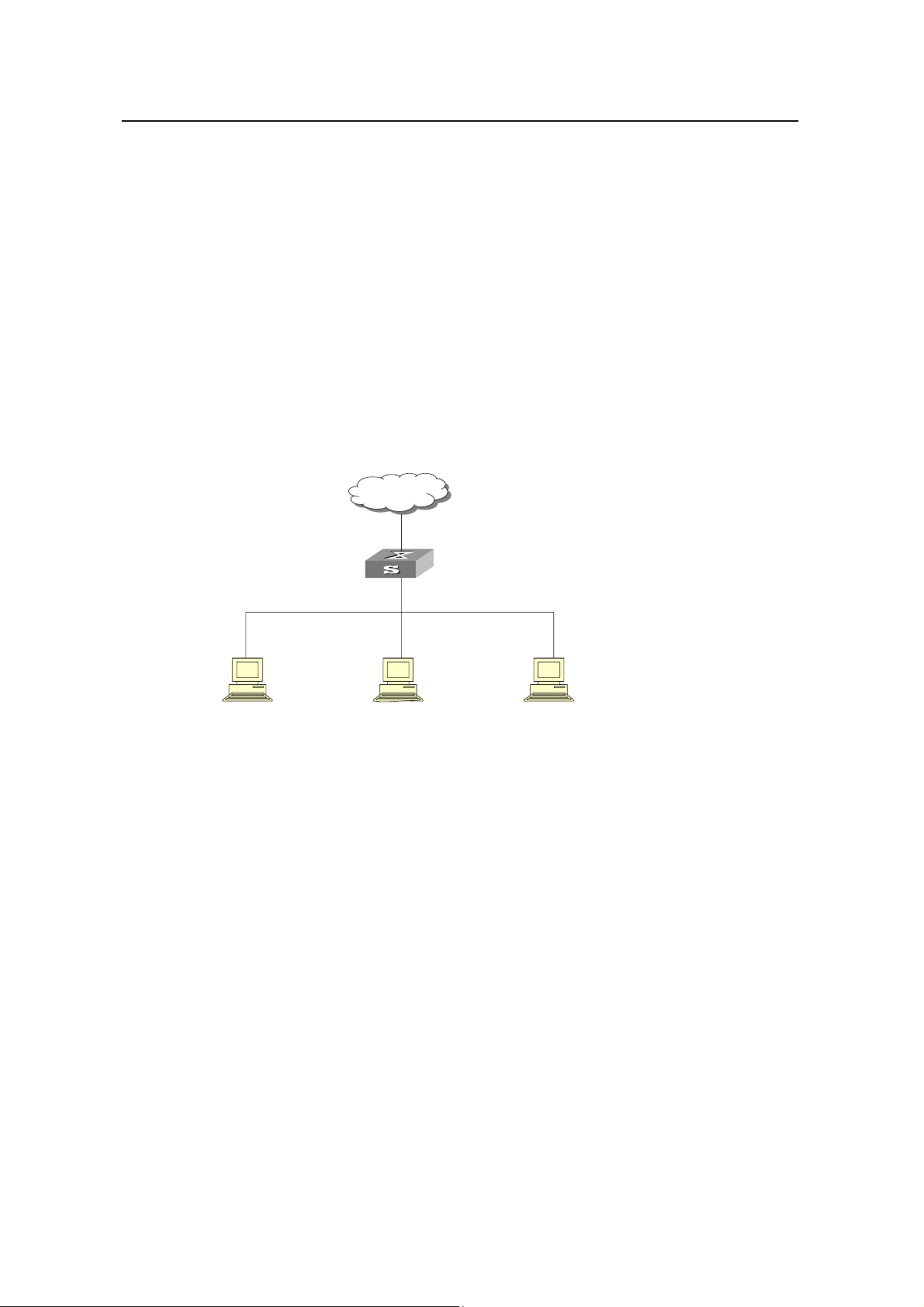
Virtual Router Redundancy Protocol (VRRP) is a fault-tolerant protocol. In general, a
default route (for example, 10.100.10.1 as shown in the following internetworking
diagram) will be configured for every host on a network, so that the pa ckets destined to
some other network segment from the host will go through the default route to the Layer
3 Switch, implementing communication between the host and the external network. If
Switch is down, all the hosts on this segment taking Switch as the next-hop on the
default route will be disconnected from the external network.
Network
Switch
10.100.10.1
10.100.10.7 10.100.10.8 10.100.10.9
Host 1 Host 2 Host 3
Ethernet
Figure 1-1 Network diagram for LAN
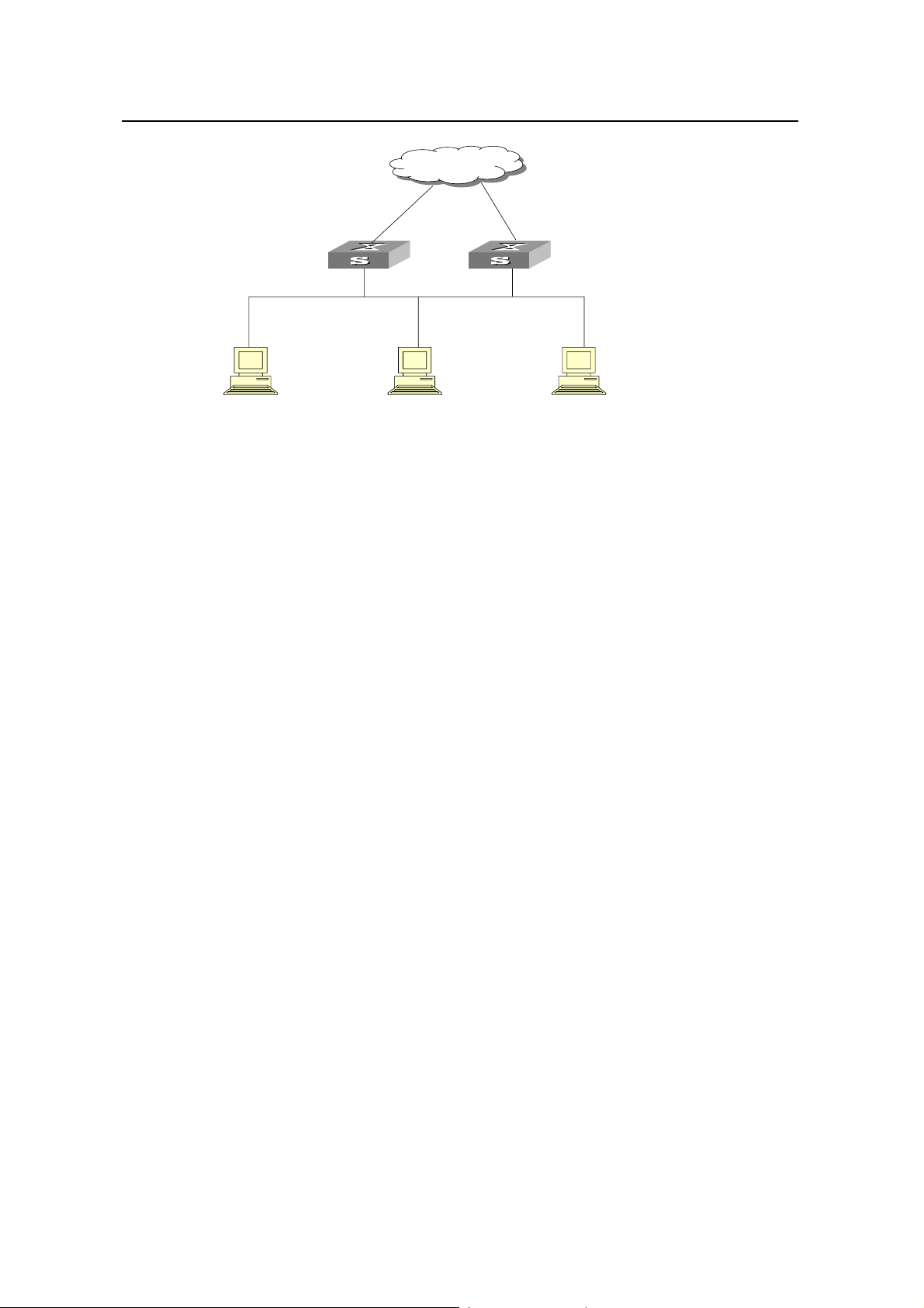
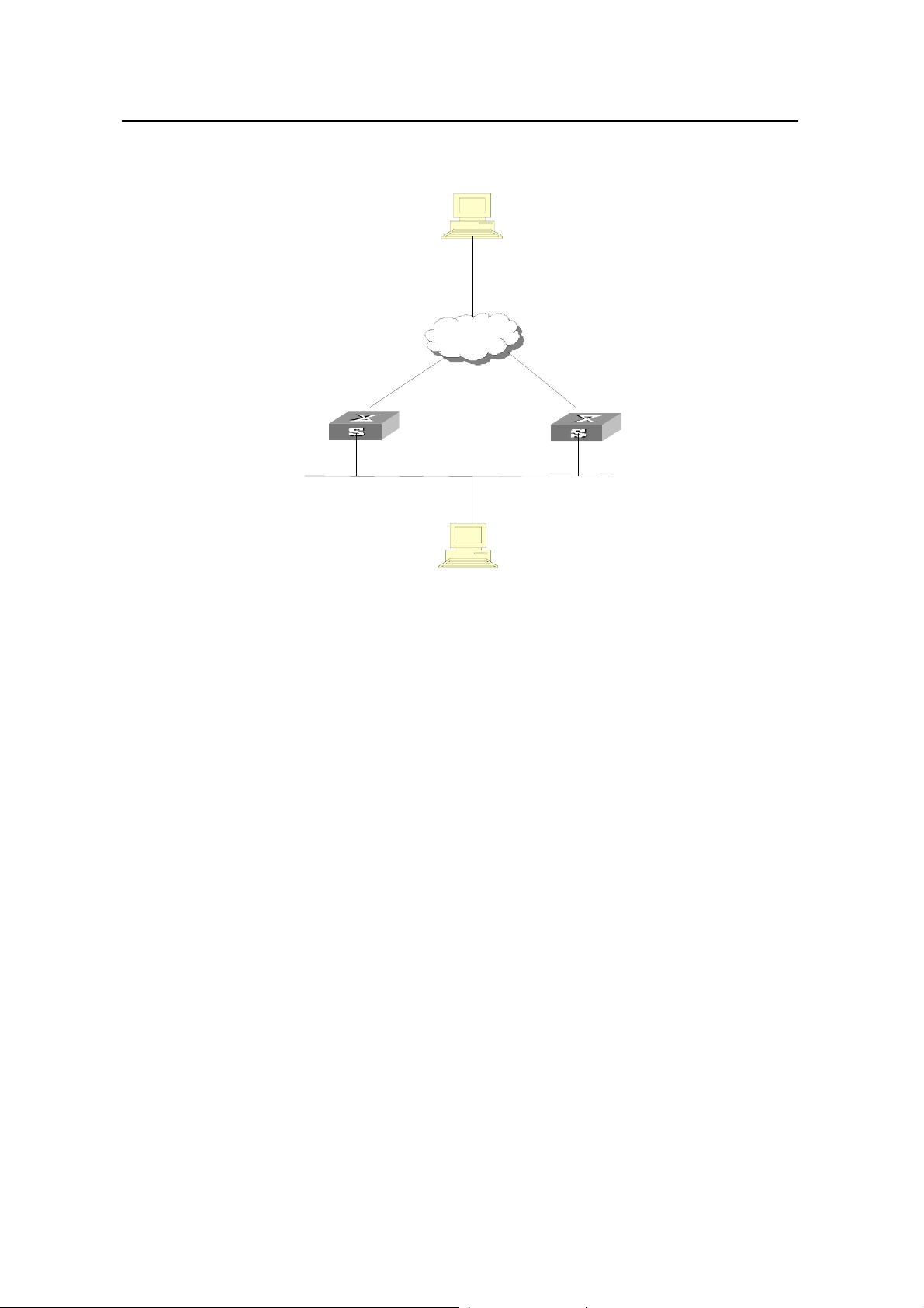
VRRP, designed for LANs with multicast and broadcast capabilities (such as Ethernet)
settles the above problem. The diagram below is taken as an example to explain the
implementation principal of VRRP. VRRP combine s a group of LAN switche s (including
a Master and several Backups) into a virtual router.
1-1
Page 3
Operation Manual – Reliability
H3C S9500 Series Routing Switches Chapter 1 VRRP Configuration
Network
Actual IP address10.100.10.2 Actual IP address10.100.10.3
Master
Virtual IP address10.100.10.1
10.100.10.7 10.100.10.8 10.100.10.9
Host 1 Host 2 Host 3
Ethernet
Virtual IP address10.100.10.1
Backup
Figure 1-2 Network diagram for virtual router
This virtual router has its own IP address: 10.100.10.1 (which can be the interface
address of a switch within the virtual router). The switches within the virtual router have
their own IP addresses (such as 10.100.10.2 for the Master switch and 10.10 0.10.3 for
the Backup switch). The host on the LAN only knows the IP address of this virtual router
10.100.10.1 (usually called as virtual IP address of virtual router), b ut not the specific IP
addresses 10.100.10.2 of the Master switch and 10.100.10.3 of the Backup switch.
They configure their own default routes as the IP address of this virtual router:
10.100.10.1. Therefore, hosts within the network will communicate with the external
network through this virtual router. If a Master switch in the virtual group breaks down,
another Backup switch will function as the new Master switch to continue serving the
host with routing to avoid interrupting the communication between the host and the
external networks.
1.2 Configuring VRRP
The following sections describe the VRRP configuration tasks:
z Enabling/Disabling the Function to Ping the Virtual IP Address
z Enabling/Disabling the Check of TTL Value of VRRP Packet
z Setting Correspondence between Virtual IP Address and MAC Address
z Adding/Deleting a Virtual IP Address
z Configuring the Priority of Switches in the Virtual Router
z Configuring Preemption and Delay for a Switch within a Virtual Router
z Configuring Authentication Type and Authentication Key
z Configuring Virtual Router Timer
z Configuring Switch to Track a Specified Interface
1-2
Page 4
Operation Manual – Reliability
H3C S9500 Series Routing Switches Chapter 1 VRRP Configuration
1.2.1 Enabling/Disabling the Function to Ping the Virtual IP Address
This operation enables or disables the function to ping the virtual IP address of the
virtual router. The standard protocol of VRRP does not support the ping function, then
the user cannot judge with ping command whether an IP address i s used by the virtual
router. If the user configure the IP address for the host same as the virtual IP address of
the virtual router, then all messages in this segment will be forwarded to the host.
So H3C S9500 Series Routing Switches (hereinafter referred to as S9500 series)
provide the ping function to ping the virtual IP address of the virtual router.
Perform the following configuration in system view.
Table 1-1 Enable/disable the ping function
Operation Command
Enable to ping the virtual IP address
Disable to ping the virtual IP address
By default, the function to ping the virtual IP address is disabled.
Y ou should set the ping function before configuring the virtual router . If a virtual router i s
already established on the switch, it is not allowed to use the vrrp ping-enable
command and the undo vrrp ping-enable command to modify the configuration any
more.
vrrp ping-enable
undo vrrp ping-enable
1.2.2 Enabling/Disabling the Check of TTL Value of VRRP Packet
This operation configures whether to check TTL value of VRRP packet on the Backup
switch. The TTL value must be 225. If the Backup switch find TTL is not 225 when
receiving VRRP packet, the packet will be discarded.
Perform the following configuration in VLAN interface view.
Table 1-2 Enable/disable the check of TTL value of VRRP packet
Operation Command
Disable the check of TTL value of VRRP packet
Enable the check of TTL value of VRRP packet
By default, the switch checks TTL value of VRRP packets.
vrrp un-check ttl
undo vrrp un-check ttl
1.2.3 Setting Correspondence between Virtual IP Address and MAC Address
This operation sets correspondence between the virtual lP address and the MAC
address. In the standard protocol of VRRP, the virtual IP address of the virtual router
1-3
Page 5
Operation Manual – Reliability
H3C S9500 Series Routing Switches Chapter 1 VRRP Configuration
corresponds to the virtual MAC address, to ensure correct data forwarding in the
sub-net.
Due to the chips installed, some switches support matching one IP address to multiple
MAC addresses.
S9500 series not only guarantee correct data forwarding in the sub-net, but also
support such function: the user can choose to match the virtual IP address with the real
MAC address or virtual MAC address of the routing interface.
The following commands can be used to set correspondence between the IP address
and the MAC address.
Perform the following configuration in system view.
Table 1-3 Set correspondence between virtual IP address and MAC address
Operation Command
Set correspondence between the virtual IP
address and the MAC address
Set the correspondence to the default value
By default, the virtual IP address of the virtual router corresponds to the virtual MAC
address.
You should set correspondence between the virtual IP address of the virtual router and
the MAC address before configuring the virtual router. Otherwise, you cannot configure
the correspondence.
If you set correspondence between the IP address of the virtual router and the real
MAC address, you can configure only one virtual router on VLAN interface.
1.2.4 Adding/Deleting a Virtual IP Address
The following command is used for assigning a virtual IP address of the local segment
to a virtual router or removing an assigned virtual IP address of a virtual router from the
virtual address list.
Perform the following configuration in VLAN interface view.
vrrp method { real-mac |
virtual-mac }
undo vrrp method
Table 1-4 Add/delete a virtual IP address
Operation Command
Add a virtual IP address
Delete a virtual IP address
vrrp vrid virtual-router-ID virtual-ip virtual-address
undo vrrp vrid virtual-router-ID [ virtual-ip
virtual-address ]
The virtual-router-ID covers the range from 1 to 255.
1-4
Page 6

Operation Manual – Reliability
H3C S9500 Series Routing Switches Chapter 1 VRRP Configuration
The virtual-address can be an unused address in the network segment where the
virtual router resides, or the IP address of an interface in the virtual router. If the IP
address is of the switch in the virtual router , it can also be configured as virtual-address.
In this case, the switch will be called an IP Address Owner. When adding the first IP
address to a virtual router , the system will cr eate a new virtual router accordingly. When
adding a new address to this virtual router thereafter, the system will directly add it into
the virtual IP address list.
After the last virtual IP address is removed from the virtual router, the whole virtual
router will also be removed. That is, there is no more virtual router on the interface any
more and any configuration of it is invalid accordingly.
1.2.5 Configuring the Priority of Switches in the Virtual Router
The status of each switch in the virtual router will be determined by its priority in VRRP.
The switch with the highest priority will become the Master.
Perform the following configuration in VLAN interface view.
Table 1-5 Configure the priority of switches in the virtual router.
Operation Command
Configure the priority of switches in the
virtual router.
Clear the priority of switches in the
virtual router.
vrrp vrid virtual-router-ID priority
priority
undo vrrp vrid virtual-router-ID priority
The priority ranges from 0 to 255. The greater the number, the higher the priority.
However the value can only be taken from 1 to 254. T he priority 0 is reserved for special
use and 255 is reserved for the IP address owner by the syste m.
By default, the priority is 100.
Note:
The priority for IP address owner is always 255, which cannot be configured otherwise.
1.2.6 Configuring Preemption and Delay for a Switch within a Virtual Router
Once a switch in the virtual router becomes the Master switch, so long as it still
functions properly, other switches, even configured with a higher priority later, cannot
become the Master switch unless they are configured to work in preemption mode. The
switch in preemption mode will become the Master switch, when it finds its own priority
1-5
Page 7

Operation Manual – Reliability
H3C S9500 Series Routing Switches Chapter 1 VRRP Configuration
is higher than that of the current Master switch. Accordingly, the former Master switch
will become the Backup switch.
Together with preemption settings, a delay can also be set. In this way, a Backup will
wait for a period of time before becoming a Master . In an un stable network if the Backup
switch has not received the packets from the Master switch punctually, it will become
the Master switch. However , the failure of Backup to receive the packets may be due to
network congestion, instead of the malfunction of the Master switch. In this case, the
Backup will receive the packet after a while. The delay settings can thereby avoid the
frequent status changing.
Perform the following configuration in VLAN interface view.
Table 1-6 Configure preemption and delay for a switch within a virtual router
Operation Command
Enable the preemption mode and
configure a period of delay.
Disable the preemption mode.
vrrp vrid virtual-router-ID preempt-mode
[ timer delay delay-value ]
undo vrrp vrid virtual-router-ID
preempt-mode
The delay ranges from 0 to 255, measured in seconds. By default, the preemption
mode is preemption with a delay of 0 second.
Note:
If preemption mode is cancelled, the delay time will automatically become 0 second.
1.2.7 Configuring Authentication Type and Authentication Key
VRRP provides following authentication types:
z simple: Simple character authentication
z md5: MD5 authentication
In a network under possible security threat, the authentication type can be set to
simple. Then the switch will add the authentication key into the VRRP packets before
transmitting it. The receiver will compare the authentication key of the packet with the
locally configured one. If they are the same, the packet will be taken as a true and legal
one. Otherwise it will be regarded as an illegal packet to be discarded. In this case, an
authentication key not exceeding 8 characters should be configured.
In a totally unsafe network, the authentication type can be set to md5. The switch will
use the authentication type and MD5 algorithm provided by the Authentication Header
1-6
Page 8

Operation Manual – Reliability
H3C S9500 Series Routing Switches Chapter 1 VRRP Configuration
to authenticate the VRRP packets. In this case an authentication key not exceeding 8
characters should be configured.
Those packets failing to pass the authentication will be discarded and a trap p acket will
be sent to the network management system.
Perform the following configuration in VLAN interface view.
Table 1-7 Configure authentication type and authentication key
Operation Command
Configure authentication type and
authentication key
Remove authentication type and
authentication key
The authentication key is case sensitive.
Note:
The same authentication type and authentication key should be configured for all VLAN
interfaces that belong to the virtual router.
1.2.8 Configuring Virtual Router Timer
The Master switch advertises its normal operation state to the switches within the
VRRP virtual router by sending them VRRP packets regularly (at adver-interval). And
the backup switch only receives VRRP packets. If the Backup has not received any
VRRP packet from the Master after a period of time (specified by master-down-interval),
it will consider the Master as down, and then take its place and b ecome the Master.
vrrp authentication-mode
authentication-type authentication-key
undo vrrp authentication-mode
Y ou can use the follo wing command to set a timer and adjust the interval, adver-interval,
between Master transmits VRRP packets. The master-down-interval of the Backup
switch is three times that of the adver-interval. The excessive network traffic or the
differences between different switch timers will result i n master-down-interval timing out
and state changing abnormally. Such problems can be solved through prolonging the
adver-interval and setting delay time. adver-interval is measured in seconds.
Perform the following configuration in VLAN interface view.
1-7
Page 9

Operation Manual – Reliability
H3C S9500 Series Routing Switches Chapter 1 VRRP Configuration
Table 1-8 Configure virtual router timer
Operation Command
Configure virtual router timer
vrrp vrid virtual-router-ID timer advertise
adver-interval
Clear virtual router timer undo vrrp vrid virtual-router-ID timer advertise
By default, adver-interval is configured to be 1.
1.2.9 Configuring Switch to Track a Specified Interface
VRRP interface track function has expanded the backup function. Backup is provided
not only to the interface where the virtual router resides, but also to some other
malfunctioning switch interface. By implementing the following command you can track
some interface.
If the interface which is tracked is Down, the priority of the switch including the int erface
will reduce automatically by the value specified by value-reduced, thus resulting in
comparatively higher priorities of other switches within the virtual router, one of which
will turn to Master switch so as to track this interface.
Perform the following configuration in VLAN interface view.
Table 1-9 Configure switch to track a specified interface
Operation Command
Configure the switch to
track a specified interface
Stop tracking the specified
interface
vrrp vrid virtual-router-ID track vlan-interface
interface-number [ reduced value-reduced ]
undo vrrp vrid virtual-router-ID track [ vlan-interface
interface-number ]
By default, value-reduced is taken 10.
Note:
z When the switch is an IP address owner, its interfaces cannot be tracked.
z If the interface tracked is up again, the corresponding priority of the switch, including
the interface, will be restored automatically
z You can only track up to eight interfaces in one virtual router.
1-8
Page 10

Operation Manual – Reliability
H3C S9500 Series Routing Switches Chapter 1 VRRP Configuration
1.3 Displaying and debugging VRRP
After the above configuration, execute display command in any view to display the
running of the VRRP configuration, and to verify the configuration. Execute debugging
command in user view to debug VRRP configuration.
Table 1-10 Display and debug VRRP
Operation Command
Display VRRP state information
Display VRRP statistics
information
Display VRRP summary
information
Clear the statistics information
about VRRP
Enable VRRP debugging. debugging vrrp { state | packet | error }
Disable VRRP debugging. undo debugging vrrp { state | packet | error }
You can enable VRRP debugging to check its running. You may choose to enable
VRRP packet debugging (option as packet), VRRP state debugging (option as state),
and/or VRRP error debugging (option as error). By default, VRRP debugging is
disabled.
display vrrp [ interface vlan-interface
interface-number [ virtual-router-ID ] ]
display vrrp statistics [ vlan-interface
interface-number [ virtual-router-ID ]
display vrrp summary
reset vrrp statistics [ vlan-interface
interface-number [ virtual-router-ID ] ]
1.4 VRRP Configuration Example
1.4.1 VRRP Single Virtual Router Example
I. Networking requirements
Host A uses the VRRP virtual router which combines switch A and switch B as its
default gateway to access host B on the Internet.
VRRP virtual router information includes: virtual router ID1, virtual IP address
202.38.160.111, switch A as the Master and switch B as the Backup allowed
preemption.
1-9
Page 11
Operation Manual – Reliability
H3C S9500 Series Routing Switches Chapter 1 VRRP Configuration
II. Networking diagram
10.2.3.1
Host B
Internet
VLAN-interface3: 10.100.10.2
Switch_A
VLAN-interface2: 202.38.160.1
Virt ual IP addr ess: 202.38.1 60.111
202.38.160.3
Host A
Switch_B
VLAN-interface2: 202.38.160.2
Figure 1-3 Network diagram for VRRP configuration
III. Configuration Procedure
Configure switch A
# Configure VLAN 2.
[LSW-A] vlan 2
[LSW-A-vlan2] interface vlan 2
[LSW-A-vlan-interface2] ip address 202.38.160.1 255.255.255.0
[LSW-A-vlan-interface2] quit
# Configure VRRP.
[LSW-A] vrrp ping-enable
[LSW-A] interface vlan 2
[LSW_A-vlan-interface2] vrrp vrid 1 virtual-ip 202.38.160.111
[LSW_A-vlan-interface2] vrrp vrid 1 priority 110
[LSW-A-vlan-interface2] vrrp vrid 1 preempt-mode
Configure switch B
# Configure VLAN2.
[LSW-B] vlan 2
[LSW-B-vlan2] interface vlan 2
[LSW-B-vlan-interface2] ip address 202.38.160.2 255.255.255.0
1-10
Page 12

Operation Manual – Reliability
H3C S9500 Series Routing Switches Chapter 1 VRRP Configuration
[LSW-B-vlan-interface2] quit
# Configure VRRP.
[LSW-B] vrrp ping-enable
[LSW-B] interface vlan 2
[LSW-B-vlan-interface2] vrrp vrid 1 virtual-ip 202.38.160.111
[LSW-B-vlan-interface2] vrrp vrid 1 preempt-mode
The virtual router can be used soon after configuration. Host A can configure the default
gateway as 202.38.160.111.
Under normal conditions, switch A functions as the gateway, but when switch A is
turned off or malfunctioning, switch B will function as the gateway instead.
Configure preemption mode for switch A, so that it can resume its gateway function as
the Master after recovery.
1.4.2 VRRP Tracking Interface Example
I. Networking requirements
Even when switch A is still functioning, it may want switch B to function as gateway
when the Internet interface connected with it does not function properly. This can be
implemented by configuration of tracking interface.
In simple language, the virtual router ID is set as 1 with additional configurations of
authorization key and timer.
II. Networking diagram
See Figure 1-3.
III. Configuration Procedure
Configure switch A
# Configure VLAN2.
[LSW-A] vlan 2
[LSW-A-vlan2] interface vlan 2
[LSW-A-vlan-interface2] ip address 202.38.160.1 255.255.255.0
[LSW-A-vlan-interface2] quit
# Enable the function to ping the virtual IP address of virtual router.
[LSW-A ] vrrp ping-enable
# Create a virtual router.
[LSW-A] interface vlan 2
[LSW_A-vlan-interface2] vrrp vrid 1 virtual-ip 202.38.160.111
# Set the priority for the virtual router.
[LSW_A-vlan-interface2] vrrp vrid 1 priority 110
1-11
Page 13

Operation Manual – Reliability
H3C S9500 Series Routing Switches Chapter 1 VRRP Configuration
# Set the authentication key for the virtual router.
[LSW_A-vlan-interface2] vrrp authentication-mode md5 switch
# Set Master to send VRRP packet s every 5 seconds.
[LSW_A-vlan-interface2] vrrp vrid 1 timer advertise 5
# Track an interface.
[LSW_A-vlan-interface2] vrrp vrid 1 track vlan-interface 3 reduced 30
Configure switch B
# Configure VLAN2.
[LSW-B] vlan 2
[LSW-B-vlan2] interface vlan 2
[LSW-B-vlan-interface2] ip address 202.38.160.2 255.255.255.0
[LSW-B-vlan-interface2] quit
# Enable the function to ping the virtual IP address of virtual router.
[LSW-B] vrrp ping-enable
# Create a virtual router.
[LSW-B] interface vlan 2
[LSW_B-vlan-interface2] vrrp vrid 1 virtual-ip 202.38.160.111
# Set the authentication key for the virtual router.
[LSW_B-vlan-interface2] vrrp authentication-mode md5 switch
# Set Master to send VRRP packet s every 5 seconds.
[LSW_B-vlan-interface2] vrrp vrid 1 timer advertise 5
Under normal conditions, switch A functions as the gateway, but when the interface
vlan-interface 3 of switch A is down, its priority will be reduced by 30, lower than that of
switch B so that switch B will preempt the Master for gateway services instead.
When vlan-interface3, the interface of switch A, recovers, this switch will resume its
gateway function as the Master.
1.4.3 Multiple Virtual Routers Example
I. Networking requirements
A Switch can function a s th e backup switch for many virtual routers.
Such a multi-backup configuration can implement load balancing. For example, switch
A as the Master switch of virtual router 1 can share the responsibility of the backup
switch for virtual router 2 and vice versa for switch B. Some hosts employ virtual router
1 as the gateway , whil e others employ virtual router 2 as the gateway. In this way , both
load balancing and mutual backup are implemented.
1-12
Page 14

Operation Manual – Reliability
H3C S9500 Series Routing Switches Chapter 1 VRRP Configuration
II. Networking diagram
Refer to Figure 1-3.
III. Configuration Procedure
Configure switch A
# Configure VLAN2.
[LSW-A] vlan 2
[LSW-A-vlan2] interface vlan 2
[LSW-A-vlan-interface2] ip address 202.38.160.1 255.255.255.0
# Create virtual router 1.
[LSW_A-vlan-interface2] vrrp vrid 1 virtual-ip 202.38.160.111
# Set the priority for the virtual router.
[LSW_A-vlan-interface2] vrrp vrid 1 priority 150
# Create virtual router 2.
[LSW_A-vlan-interface2] vrrp vrid 2 virtual-ip 202.38.160.112
Configure switch B
# Configure VLAN2.
[LSW-B] vlan 2
[LSW-B-vlan2] interface vlan 2
[LSW-B-vlan-interface2] ip address 202.38.160.2 255.255.255.0
# Create virtual router 1.
[LSW_B-vlan-interface2] vrrp vrid 1 virtual-ip 202.38.160.111
# Create virtual router 2.
[LSW_B-vlan-interface2] vrrp vrid 2 virtual-ip 202.38.160.112
# Set the priority for the virtual router.
[LSW_B-vlan-interface2] vrrp vrid 2 priority 110
Note:
Multiple virtual routers are often used in actual network applications.
1.5 Troubleshooting VRRP
As the configuration of VRRP is not very complicated, almost all the malfunctions can
be found through viewing the configuration and debugging info rmation. He re are som e
possible failures you might meet and the corresponding troubleshooting methods.
1-13
Page 15

Operation Manual – Reliability
H3C S9500 Series Routing Switches Chapter 1 VRRP Configuration
I. Fault 1: Frequent prompts of configuration errors on the console
This indicates that an incorrect VRRP packet has be e n received. It may be be ca use of
the inconsistent configuration of another switch within the virtual router, or the attempt
of some devices to send out illegal VRRP packets. The first po ssible fault can be solved
through modifying the configuration. And as the second possibility is caused by the
malicious attempt of some devices, non-technical measures should be resorted to.
II. Fault 2: More than one Masters existing within the same virtual router
There are also 2 reasons. One is short time coexistence of many Master switches,
which is normal and needs no manual intervention. Another is the long time
coexistence of many Master switches, which may be because switches in the virtual
router cannot receive VRRP packets from each other, or receive some illegal packets.
To solve such problems, an attempt should be made to ping among the many Master
switches, and if such an attempt fails, check the device connectivity. If they can be
pinged, check the VRRP configuration. For the config uratio n of the sam e VRRP virtual
router, complete consistence for the number of virtual IP addresses, each virtual IP
address, timer duration and authentication type must be guaranteed.
III. Fault 3: Frequent switchover of VRRP state
Such problem occurs when the virtual router timer duration is set too short. So the
problem can be solved through prolonging this duration or configuring the preemption
delay.
1-14
Page 16

Operation Manual – Reliability
H3C S9500 Series Routing Switches Chapter 2 HA Configuration
Chapter 2 HA Configuration
2.1 Introduction to HA
HA (high availability) is to achieve a high availability of the system and to recover the
system as soon as possible in the event of SRPU failures so as to shorten the MTBF
(Mean Time Between Failure) of the system.
The functions of HA are mainly implemented by the application running on master and
slave boards. The two boards are working in the master-slave mode: one board works
in master mode, the other work in slave mode. If the master-slave system detects a
fault in the master board, a hot master-slave switchover will be performed automatically .
The slave board will try to connect and control the system bus while the original master
board will try to disconnect from the bus. Thus, the master-slave switchover of the
active system is completed, and at the same time the original master board is reset to
recover as soon as possible and then function as the slave board. Even if the master
board fails, the slave board can also take its role to ensure the normal operation, and
the system can recover as soon as possible.
S9500 series support hot swap of master and slave boards. The hot swap of master
boards will cause master-slave switchover.
S9500 series support manual master-slave switchover. You can change the current
board state manually by executing command.
The configuration file of slave is copied from master board at the same time. This can
ensure that the slave system continues to operate in the same configuration as that of
the original active system after the slave system has taken plac e of the active system.
S9500 series support automatic synchronization. The active system stores its
configuration file and backup the configuration file to the slave system simultaneously
when the master's configuration file is modified, ensuring the consistency of the
configurations of the active system and slave system.
Besides, the system can monitor the power supply and the working environment of the
system and give timely alarms to avoid the escalation of failures and ensure safe
operations of the system.
Caution:
The S9500 active and standby boards must both be in position and run the same
version of program. Otherwise, the switch cannot operate normally.
2-1
Page 17

Operation Manual – Reliability
H3C S9500 Series Routing Switches Chapter 2 HA Configuration
2.2 Configuring HA
The following sections describe the HA config uration t asks:
z Restarting the Slave System Manually
z Starting the Master-Slave Switchover Manually
z Enabling/Disabling Automatic Synchronization
z Synchronizing the Configuration File Manually
z Configuring the Load Mode of the
2.2.1 Restarting the Slave System Manually
In the environment in which the slave system is available, the user can restart the slave
system manually.
Perform the following configuration in user view.
Table 2-1 Restart the slave system manually
Operation Command
Restart the slave system manually
slave restart
2.2.2 Starting the Master-Slave Switchover Manually
In the environment in which the slave board is available and master in real-time ba ckup
state, the user can inform the slave board of a master-slave switchover by using a
command if he expects the slave board to operate in place of the master board. After
the switchover, the slave board will control the system and the origi nal master board will
be forced to reset.
Perform the following configuration in user view.
Table 2-2 Start the master-slave switchover manually
Operation Command
Start the master-slave switchover manually
The switchover manually will be ineffective if user set the system forbid master-slave
switchover manually.
slave switchover
2.2.3 Enabling/Disabling Automatic Synchronization
S9500 series support automatic synchronization. The active system stores its
configuration file and backup the configuration file to the slave system simultaneously
when the master's configuration file is modified, ensuring the consistency of the
configurations of the active system and slave system.
2-2
Page 18
Operation Manual – Reliability
H3C S9500 Series Routing Switches Chapter 2 HA Configuration
You can enable/disable automatic synchronize of S9500 series.
Perform the following configuration in system view.
Table 2-3 Enable/Disable automatic synchronization
Operation Command
Enable automatic synchronization
Disable automatic synchronization
slave auto-update config
undo slave auto-update config
By default, the automatic synchronization of system is enabled.
2.2.4 Synchronizing the Configuration File Manually
Although the system can perform the synchronization automatically, the
synchronization can occur only when the master board saves its con figuration file. If the
user expects to determine the backup of the configuration file by himself, he can do it
manually to backup the configuration file saved in the master board.
Perform the following configuration in user view.
Table 2-4 Synchronize the configuration file manually
Operation Command
Synchronize the configuration file manually
slave update configuration
This operation can backup the configuration file to the slave board only if a slave
system is available. The configuration file will be fully copied once at every time the
operation is executed.
2.2.5 Configuring the Load Mode of the Master and Slave boards
S9500 series support two kinds of load modes (balance and single) between the
master and slave boards. You can use the xbar command to configure XBar (cross bar)
load mode.
Perform the following configuration in system view.
Table 2-5 Configure the XBar load mode
Operation Command
Configure the load mode of the master
and slave boards
By default, the load mode of the master and slave boards is load-single.
xbar [ load-balance | load-single ]
2-3
Page 19

Operation Manual – Reliability
H3C S9500 Series Routing Switches Chapter 2 HA Configuration
Caution:
When a single SRPU is in position, the load-balance mode is not effective and the
SRPU changes to the load-single mode automatically.
2.3 Displaying and Debugging HA Configuration
After the above configuration, execute display command in relevant view to display the
running of the ACL configuration, and to verify the configuration. Execute debugging
command in user view to enable HA module debugging function.
Perform the following configuration in relevant view.
Table 2-6 Display and debug HA configuration
Operation Command
Display the status of the master and
slave boards(any view)
Display the load mode of the master and
slave boards(system view)
Enable the debugging information
output of the HA module(user view)
Disable the debugging information
output of the HA module(user view)
2.4 HA Configuration Example
I. Network requirements
Take the master board out and make the slave board take over the work of the master
to ensure the normal operation.
II. Configuration procedure
# Synchronize the configuration file manually.
<H3C>slave update configuration
display switchover state [ slot-id ]
display xbar
debugging ha { all | event | message |
state }
undo debugging ha { all | event |
message | state }
# Display the switchover state.
<H3C>display switchover state
# Start the master-slave switchover manually after you confirm and press <Enter>.
<H3C>slave switchover
Caution!!! Confirm to switch slave to master[Y/N]?y
2-4
 Loading...