

Page 1

HPE G3 KVM Console Switch
Abstract
This document is for the person who installs, administers, and troubleshoots servers and storage systems. Hewlett Packard Enterprise
Part Number: 785985-001R
November 2015
Edition: 2
User Guide
assumes you are qualified in the servicing of computer equipment and trained in recognizing hazards in products with hazardous energy
levels.
Page 2

© Copyright 2014, 2015 Hewlett Packard Enterprise Development LP
The information contained herein is subject to change without notice. The only warranties for Hewlett Packard Enterprise products and services
are set forth in the express warranty statements accompanying such products and services. Nothing herein should be construed as constituting
an additional warranty. Hewlett Packard Enterprise shall not be liable for technical or editorial errors or omissions contained herein.
Confidential computer software. Valid license from Hewlett Packard Enterprise required for possession, use or copying. Consistent with FAR
12.211 and 12.212, Commercial Computer Software, Computer Software Documentation, and Technical Data for Commercial Items are
licensed to the U.S. Government under vendor’s standard commercial license.
Microsoft®, Windows®, and Windows Server® are trademarks of the Microsoft group of companies.
Page 3

Contents
Overview................................................................................................................................................ 7
HPE G3 KVM Console Switch overview .................................................................................................................. 7
Installing the HPE G3 KVM Console Switch ........................................................................................... 8
Rack-mount safety instructions ................................................................................................................................ 8
Installation checklist ................................................................................................................................................. 8
Console switch kit contents ........................................................................................................................... 8
Required items not included .......................................................................................................................... 8
Required tools ............................................................................................................................................... 9
Rack-mounting the console switch ........................................................................................................................... 9
Performing a standard-mount installation ...................................................................................................... 9
Performing a cantilever-mount installation .................................................................................................. 10
Performing a side-mount installation ........................................................................................................... 11
Console switch components ................................................................................................................................... 14
Connecting the local console switch ...................................................................................................................... 15
Remote access key ................................................................................................................................................ 15
Connecting the RAK .................................................................................................................................... 16
Installing the interface adapter ............................................................................................................. 18
Integrating the IA .................................................................................................................................................... 18
Connecting the IA ................................................................................................................................................... 18
Cascading console switches ................................................................................................................ 19
Compatible console switch models ........................................................................................................................ 19
IP Console Switch ....................................................................................................................................... 19
Cascading two HPE KVM Server Console Switch G3 systems ............................................................................. 20
Cascading matrix .................................................................................................................................................... 21
Local port operation ............................................................................................................................. 22
Overview ................................................................................................................................................................ 22
Accessing the Main dialog box .................................................................................................................... 22
Viewing servers ...................................................................................................................................................... 23
Viewing the Port column .............................................................................................................................. 23
Viewing the Server Status column .............................................................................................................. 23
Selecting servers .................................................................................................................................................... 24
Soft switching ......................................................................................................................................................... 24
Soft switching to a server ............................................................................................................................ 24
Configuring switches for soft switching........................................................................................................ 24
Soft switching to a previous server .............................................................................................................. 24
Disconnecting from a server ........................................................................................................................ 24
Using basic OSD navigation keys .......................................................................................................................... 25
Configuring the Setup dialog box ........................................................................................................................... 25
Accessing the Setup dialog box .................................................................................................................. 26
Managing routine tasks for servers ............................................................................................................. 26
Changing the display behavior ............................................................................................................................... 26
Accessing the Menu dialog box ................................................................................................................... 27
Selecting the display order of servers ......................................................................................................... 27
Selecting and setting the OSD hot key command ....................................................................................... 27
Setting a screen delay time ......................................................................................................................... 27
Setting local console switch security ...................................................................................................................... 28
Accessing the Security dialog box ............................................................................................................... 28
Changing the password ............................................................................................................................... 28
Setting password protection ........................................................................................................................ 28
Logging in to the console switch ................................................................................................................. 29
Removing the password protection ............................................................................................................. 29
Contents 3
Page 4

Resetting a console switch password.......................................................................................................... 29
Exiting screen saver mode .......................................................................................................................... 30
Activating Screen Saver mode without password protection....................................................................... 30
Deactivating the screen saver ..................................................................................................................... 31
Controlling the status flag ....................................................................................................................................... 31
Accessing Flag Setup dialog box ................................................................................................................ 31
Displaying the status flag............................................................................................................................. 32
Setting the OSD interface language ....................................................................................................................... 32
Assigning device types ........................................................................................................................................... 33
Accessing Devices dialog box ..................................................................................................................... 33
Modifying device types ................................................................................................................................ 33
Assigning server names ......................................................................................................................................... 34
Accessing the Names dialog box ................................................................................................................ 34
Assigning names to servers ........................................................................................................................ 35
Changing the keyboard language .......................................................................................................................... 35
Accessing the Keyboard dialog box ............................................................................................................ 36
Selecting the keyboard language ................................................................................................................ 36
Setting up a scan pattern ....................................................................................................................................... 36
Accessing the Scan dialog box ................................................................................................................... 37
Adding servers to the scan setup ................................................................................................................ 37
Removing servers from the scan setup ....................................................................................................... 38
Activating Scan mode .................................................................................................................................. 38
Deactivating Scan mode.............................................................................................................................. 38
Configuring the Switch and Share modes .............................................................................................................. 38
Accessing the Switch dialog box ................................................................................................................. 39
Setting the Switch and Share modes .......................................................................................................... 39
Configuring network settings .................................................................................................................................. 39
Managing console switch tasks using the OSD ..................................................................................................... 40
Accessing the Commands dialog box ......................................................................................................... 40
Displaying version information ............................................................................................................................... 40
Accessing the Version dialog box ............................................................................................................... 40
Using the on-board Web interface (OBWI) ........................................................................................... 42
Setting up the built-in web server ........................................................................................................................... 42
Launching the OBWI .............................................................................................................................................. 42
Connecting to the remote OBWI through a firewall ..................................................................................... 44
Managing console switches ................................................................................................................................... 45
Viewing system information .................................................................................................................................... 45
Generating a certificate .......................................................................................................................................... 47
Rebooting and upgrading the KVM console switch ................................................................................................ 47
Rebooting the KVM console switch ............................................................................................................. 47
Upgrading the console switch firmware ....................................................................................................... 48
Saving and restoring configurations and user databases ........................................................................... 48
Identity and location information ............................................................................................................................. 49
LDS and PDS .............................................................................................................................................. 49
Viewing version information ................................................................................................................................... 50
Network settings ..................................................................................................................................................... 50
General settings .......................................................................................................................................... 51
Address settings .......................................................................................................................................... 51
SNMP ..................................................................................................................................................................... 51
Configuring SNMP parameters.................................................................................................................... 52
Auditing event settings ........................................................................................................................................... 52
Setting event destinations ...................................................................................................................................... 52
Configuring an IA .................................................................................................................................................... 52
Deleting an IA .............................................................................................................................................. 53
Upgrading an IA........................................................................................................................................... 53
Launching a session ............................................................................................................................................... 53
General session settings ............................................................................................................................. 54
Active sessions ....................................................................................................................................................... 54
Local user account settings .................................................................................................................................... 54
Access levels ............................................................................................................................................... 55
Contents 4
Page 5

DSView software settings ....................................................................................................................................... 55
Closing a KVM session .......................................................................................................................................... 56
Managing remote servers through the Video Session Viewer .............................................................. 57
About the Video Session Viewer ............................................................................................................................ 57
Video Session Viewer window..................................................................................................................... 58
Changing the toolbar .............................................................................................................................................. 59
Adjusting the window size ...................................................................................................................................... 59
Adjusting the view .................................................................................................................................................. 59
Refreshing the image ............................................................................................................................................. 60
Manually adjusting the video settings ..................................................................................................................... 60
Target video settings ................................................................................................................................... 62
Automatic video adjustment ........................................................................................................................ 62
Video test pattern ........................................................................................................................................ 62
Color settings............................................................................................................................................... 62
Noise settings ......................................................................................................................................................... 62
Mouse settings ....................................................................................................................................................... 63
Cursor type .................................................................................................................................................. 63
Mouse scaling.............................................................................................................................................. 64
Mouse alignment and synchronization ........................................................................................................ 65
Keyboard pass-through .......................................................................................................................................... 65
Macros .................................................................................................................................................................... 65
Saving the view ...................................................................................................................................................... 65
Closing a Video Viewer session ............................................................................................................................. 66
Terminal operation ............................................................................................................................... 67
Terminal operation overview .................................................................................................................................. 67
Network configuration ............................................................................................................................................. 67
Console Main Menu options ................................................................................................................................... 67
Firmware Management................................................................................................................................ 68
Enable Debug Messages ............................................................................................................................ 68
Set/Change Password ................................................................................................................................. 68
Restore Factory Defaults ............................................................................................................................. 68
Reset Switch................................................................................................................................................ 68
Set Web Interface Ports .............................................................................................................................. 68
Exit............................................................................................................................................................... 68
Troubleshooting ................................................................................................................................... 69
Connection length requirements ............................................................................................................................ 69
DIAG port pinout ..................................................................................................................................................... 69
Troubleshooting table ............................................................................................................................................. 69
Warranty and regulatory information .................................................................................................... 71
Warranty information .............................................................................................................................................. 71
Regulatory information ........................................................................................................................................... 71
Safety and regulatory compliance ............................................................................................................... 71
Belarus Kazakhstan Russia marking ........................................................................................................... 71
Turkey RoHS material content declaration .................................................................................................. 72
Ukraine RoHS material content declaration ................................................................................................ 72
Korean notice .............................................................................................................................................. 72
Support and other resources................................................................................................................ 74
Accessing Hewlett Packard Enterprise Support ..................................................................................................... 74
Information to collect ................................................................................................................................... 74
Accessing updates ................................................................................................................................................. 74
Websites ................................................................................................................................................................. 74
Remote support ...................................................................................................................................................... 75
Acronyms and abbreviations ................................................................................................................ 76
Documentation feedback ..................................................................................................................... 78
Index .................................................................................................................................................... 79
Contents 5
Page 6

Contents 6
Page 7

Overview
HPE G3 KVM Console Switch overview
The HPE G3 KVM Console Switch is an analog KVM switch providing local access to data center servers
and remote access when using an optional RAK (AF650A).
USB, serial, and BladeSystem IAs enable direct KVM connectivity to devices. The KVM Console Switch
supports all previous IAs with the exception of the KVM Console Serial/Power G2 Interface Adapter
(AF625A).
The KVM Console Switch does not support virtual media or CAC (smart cards). IAs with VM/CAC support
provide only keyboard, video, and mouse functionality when used with the KVM Console Switch.
The KVM Console Switch provides a local OSD for local switch management and a remote web-based
OBWI for remote switch management. Access the OSD through the local port. Access the OBWI directly
from the switch using a browser. The OBWI also provides a remote KVM session to target devices when
using the optional RAK. Access the terminal console interface through the DIAG port and a terminal
screen or a PC running terminal emulation software.
Both IPv4 and IPv6 are supported by the KVM Console Switch.
Overview 7
Page 8

Installing the HPE G3 KVM Console Switch
Rack-mount safety instructions
The HPE G3 KVM Console Switch ships with rack-mounting brackets for easy integration into the rack.
Stabilize the rack in a permanent location before installing the equipment. Avoid uneven loading or
overloading of the rack cabinets.
When rack-mounting this product, consider the following factors:
• Elevated operating ambient temperature—In a closed or multi-unit rack assembly, the operating
ambient temperature of the rack environment can be greater than room ambient temperature. Install
the equipment in an environment compatible with the operating temperature.
• Reduced air flow—In the rack, the rate of air flow required for safe operation of the equipment must
not be compromised.
• Circuit overloading—When connecting the equipment to the supply circuit, consider the effect that
overloading of the circuits might have on overcurrent protection and supply wiring. Consider the
equipment nameplate ratings when addressing this concern.
• Reliable earthing—Maintain reliable earthing of rack-mounted equipment. Pay particular attention to
supply connections other than direct connections to the branch circuit, such as the use of power
strips.
• Product orientation—The equipment should not be mounted with the rear panel facing downward.
Installation checklist
Console switch kit contents
Required items not included
Before installation, refer to the following lists to be sure that all of the listed components were received.
• Console switch
• Power cords
• Rack mounting kit
• CAT5 to DB9 serial cable adapter
• Documentation kit
This kit might contain extra hardware for your convenience.
• IAs ("Installing the interface adapter" on page 18)
One IA with one of the following connections is required for each server or device.
o USB connection
o Serial connection
o HPE BladeSystem connection
• UTP CAT5 cable or higher
Installing the HPE G3 KVM Console Switch 8
Page 9

Required tools
The following tools are required for some procedures:
• Phillips screwdriver
• Cage nut insertion tool (included with your original rack hardware kit)
Rack-mounting the console switch
To install the KVM Console Switch into the rack:
WARNING: To reduce the risk of fire, do not mount this product with the rear panel, which is
the side of the KVM Console Switch with I/O connectors and the AC power inlet, facing
1. Before installing the KVM Console Switch into the rack, connect the KVM Console Switch to a power
2. Choose one of the following configurations:
Performing a standard-mount installation
1. Remove the four screws, two on each side, from the console switch.
2. Attach the short 1U brackets to the console switch using the four screws you removed.
downward (facing the floor).
source, using the power cords provided, and power on the unit.
The system health LED illuminates after a few seconds. If the system health LED does not illuminate,
be sure that the power is on, the power cord is connected, and the power source is valid.
o Standard-mount ("Performing a standard-mount installation" on page 9)
o Cantilever-mount ("Performing a cantilever-mount installation" on page 10)
o Side-mount ("Performing a side-mount installation" on page 11)
3. If not already installed, install a cage nut behind each rear rail.
Installing the HPE G3 KVM Console Switch 9
Page 10

4.
Slide the console switch into the rear of the 1U product.
5. Secure the console switch to the rails using two M-6 screws, one on each side.
Performing a cantilever-mount installation
To perform a cantilever-mount installation:
1. Remove the four screws, two on each side, from the console switch.
2. Attach the short 1U brackets to the console switch as shown in the standard-mount installation
("Performing a standard-mount installation" on page 9).
Installing the HPE G3 KVM Console Switch 10
Page 11

3.
Install up to six cage nuts.
4. Secure the console switch to the rails using the appropriate number of M-6 screws.
Performing a side-mount installation
To perform a side-mount installation:
1. Remove the four screws, two on each side, from the console switch.
Installing the HPE G3 KVM Console Switch 11
Page 12

2.
Attach the side-mounting brackets to the console switch using the four screws you removed.
3. Slide the side-mounting bracket tabs into the U locations on each side of the rack.
Installing the HPE G3 KVM Console Switch 12
Page 13

4.
Install four cage nuts into the side-mounting bracket U locations.
5. Secure the console switch to the rails using four M-6 screws, two on each side.
On some racks, you can use four sheet metal screws in place of M-6 screws and cage nuts.
Installing the HPE G3 KVM Console Switch 13
Page 14
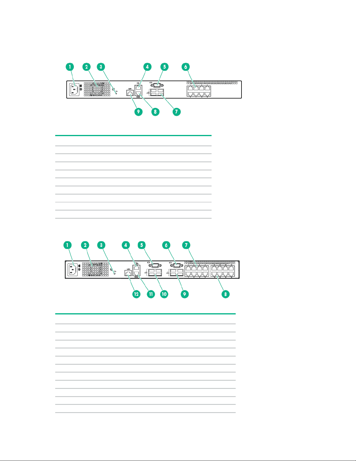
Console switch components
Item
Description
1
Power cord connector
2
Fan
3
System health LED
4
RJ-45 tiering port
5
Console port video connector
6
Server connection ports 1-8
7
Console port USB ports
8
DIAG port
9
LAN port
1
Power cord connector
2
Fan 3 System health LED
4
RJ-45 tiering port
5
Console port A video connector
6
Console port B video connector
7
Server connection ports 1-8
8
Server connection ports 9-16
9
Console port B USB ports
10
Console port A USB ports
11
DIAG port
Item Description
Installing the HPE G3 KVM Console Switch 14
Page 15

Item
Description
12
LAN port
1
Local console
2
Console switch
Connecting the local console switch
To connect the local console switch:
1. Connect the local keyboard, video, and mouse to the console switch.
WARNING: To reduce the risk of electric shock or damage to the equipment:
• Do not disable the power cord grounding plug. The grounding plug is an important safety
feature.
• Plug the power cord into a grounded (earthed) electrical outlet that is easily accessible at all
times.
• Unplug the power cord from the power supply to disconnect power to the equipment.
• Do not route the power cord where it can be walked on or pinched by items placed against
it. Pay particular attention to the plug, electrical outlet, and the point where the cord extends
2. Plug the console switch power cord into a power source.
The system health LED ("Console switch components" on page 14) flashes when the KVM Console
Switch boots up. When the system health LED is solid green, the KVM Console Switch is
operational.
3. Power on the monitor.
The following figure shows one possible configuration for the console switch system.
from the storage system.
Remote access key
Item Description
The optional USB RAK provides the following features:
• KVM remote access
Installing the HPE G3 KVM Console Switch 15
Page 16

The RAK supports a single KVM remote session. Use the RAK to manage remote operating
systems, operating system recovery, hard drive recovery or duplication, and server backup.
• DSView management software plug-in
IT administrators can use the DSView management software plug-in to securely access and monitor
target devices on multiple platforms remotely through a single web-based user interface. A single
point of access can launch a session to a device.
Manage KVM Console Switches using DSView by installing the HPE KVM plug-in for DSView.
• Local video scaling
The KVM Console Switch digitizes a video signal with a maximum resolution of 1600 x 1200 or 1680
x 1050 (widescreen). The maximum resolution depends on the cable length between the KVM
Console Switch and the devices.
• Encryption
The KVM Console Switch supports 128-bit SSL (ARCFOUR), AES, DES, and 3DES encryption of
keyboard/mouse and video sessions.
Connecting the RAK
IMPORTANT: Configure the network settings for the switch using the OSD or the DIAG port
for KVM remote access to function.
Installing the HPE G3 KVM Console Switch 16
Page 17

Connect the RAK to any USB port on the KVM Console Switch. When the RAK receives USB power, the
LED on the RAK flashes slowly, followed by rapid flashing. The rapid flashing indicates successful
enumeration. When the RAK is accepted, the LED on the RAK is continuously illuminated.
Installing the HPE G3 KVM Console Switch 17
Page 18

Installing the interface adapter
Item
Description
1
Server
Console switch
3
USB IA
4
PS/2 IA
Integrating the IA
An IA (sold separately) is required for the KVM Console Switch system to function properly. An IA
connects to the KVM Console Switch using UTP CAT5 or higher cables. The IA connects to the keyboard,
video, and mouse interfaces of the server.
NOTE: UTP CAT5 or higher cables are used throughout the examples in this guide.
Connecting the IA
To connect the IA:
1. Connect a UTP CAT5 cable or higher to the server connection port ("Console switch components"
on page 14) on the KVM Console Switch.
2. Connect the other end of the cable to the RJ-45 connector on the IA.
3. Connect the IA to the appropriate connectors on the server.
4. Repeat these steps to connect additional servers to this system, if needed.
To add server names, see "Assigning names to servers (on page 35)."
The following figure shows one possible configuration for the KVM Console Switch system with an IA.
2
Installing the interface adapter 18
Page 19

Cascading console switches
Compatible console switch models
This product supports only one level of cascading. Before cascading console switches, review the
following information.
CAUTION: Do not use interface adapters to cascade one KVM Console Switch system with
another KVM Console Switch system. If interface adapters are used to cascade these
KVM firmware upgrades cannot be done through a cascading connection. Each KVM console switch must
have its firmware updated individually.
products, undesirable operations might occur.
IP Console Switch
CAUTION: Do not use an interface adapter to cascade an IP Console Switch with an KVM
Console Switch. If an interface adapter is used to cascade these products, undesirable
operations might occur.
The following IP Console Switches can be integrated into the KVM Console Switch system. Compatible IP
Console Switch models include:
• 2 x 1 x 16 [PN AF601A]
• 4 x 1 x 16 [PN AF602A]
• 1 x 1E x 8 [PN AF620A]
• 2 x 1E x 16 [PN AF621A]
• 4 x 1E x 32 [PN AF622A]
All IP Console Switches must have the latest SoftPaq firmware upgrade when cascaded.
Cascading console switches 19
Page 20

Example of an IP Console Switch cascade configuration
1
Server
2
IA
3
UTP CAT5 cable or higher
4
UTP CAT5 cable or higher
5
KVM cable
6
Main IP Console Switch
7
Local port
8
Cascaded KVM Console Switch
Item Description
Cascading two HPE KVM Server Console Switch G3 systems
To cascade two KVM Console Switch systems:
1. Locate a UTP CAT5 cable or higher.
2. Connect one end of the UTP CAT5 cable to the server connection port on the primary console
switch.
3. Connect the other end of the UTP CAT5 cable to the RJ-45 tiering port on the secondary (cascaded)
console switch.
Cascading console switches 20
Page 21

To perform a firmware upgrade for a cascaded KVM Console Switch and all attached IAs, locally connect
[PN AF651, AF652]
G3 KVM Console Switch
[PN AF651, AF652]
KVM Console Switch G2
[PN AF651, AF652]
IP Console Switch G2 with Virtual Media
[PN AF620A, AF621A, AF622A]
G3 KVM Console Switch
[PN AF601A, AF602A]
G3 KVM Console Switch
the keyboard, monitor, and mouse to the cascaded KVM Console Switch to access the local OSD.
The following figure shows a KVM Console Switch cascaded with another KVM Console Switch. The
primary KVM Console Switch is on the top. The secondary (cascaded) KVM Console Switch is on the
bottom.
CAUTION: Do not use interface adapters to cascade one KVM Console Switch system with
another KVM Console Switch system. If interface adapters are used to cascade these
products, undesirable operations might occur.
Cascading matrix
The following table lists with which console switches the KVM Console Switch can cascade. The primary
console switch cascades to the secondary console switch.
Primary console switch Secondary console switch
G3 KVM Console Switch
G3 KVM Console Switch
G3 KVM Console Switch
IP Console Switch G2 with Virtual Media
IP Console Switch with Virtual Media
[PN AF651, AF652]
[PN AF616A, AF617A, AF626A]
[PN AF620A, AF621A, AF622A]
[PN AF651, AF652]
[PN AF651, AF652]
Cascading console switches 21
Page 22

Local port operation
Button
Description
Clear all offline IAs
Disconnect the local KVM session
Setup
Access the Setup dialog box and configure the OSD
Commands
Access the Commands dialog box
Overview
The HPE G3 KVM Console Switch system has at least one local port (based on the specific model) on the
rear panel ("Console switch components" on page 14) that enables the user to connect a keyboard,
monitor, and mouse to the HPE G3 KVM Console Switch for direct access.
Use the Main dialog box ("Accessing the Main dialog box" on page 22) to view, configure, and control
Accessing the Main dialog box
servers in the HPE G3 KVM Console Switch system.
To access the Main dialog box, choose one of the following default key sequences.
• Print Scrn
• Ctrl + Ctrl
To configure the following additional key sequences, see "Accessing the Menu dialog box (on page 27)."
• Alt + Alt
• Shift + Shift
Press the Alt, Shift, or Ctrl key twice within one second to launch the OSD. Use this key sequence where
you see Print Scrn. For more information, see "Accessing the Menu dialog box (on page 27)."
The Main dialog box appears.
Clear
Disconnect
Local port operation 22
Page 23

Viewing servers
01
The server is connected to port 01 of the 2 x 8 KVM
02
The server is connected to port 02 of the 2 x 16 KVM
You can view servers by name, port, or by the unique EID embedded in each interface adapter.
Viewing the Port column
When you launch the Main dialog box ("Accessing the Main dialog box" on page 22) for the first time, an
OSD-generated port list appears.
The Port column indicates the port to which a server is connected. For example, in the following figure, the
first number represents the port number of the first console switch and the second number represents the
port number of the cascaded console switch port to which the server is connected.
Port number
of the first
console
switch
16
14
04
05
Port number
of the
Server status
icon displayed
cascaded
console
switch
Description
Console Switch, and that KVM Console Switch is
cascaded from port 16 of the first KVM Console
Switch.
Console Switch, and that KVM Console Switch is
cascaded from port 14 of the first KVM Console
Switch.
The server is connected to the first console switch
and the interface adapter is not connected, or the
server is powered off.
The server is connected to the first console switch
and is active.
Viewing the Server Status column
The status of each server in the KVM Console Switch system is indicated by the icons in the right column
of the Main dialog box ("Accessing the Main dialog box" on page 22).
Item Description
The interface adapter is connected directly, cascaded through a KVM Console Switch, or
powered on.
The interface adapter is not connected or the server is powered off.
The interface adapter is being upgraded.
Local port operation 23
Page 24

Item Description
This symbol identifies the port to which the console switch is connected.
This symbol identifies the port to which you are connected and viewing.
This symbol identifies another active port to which you are not connected.
Selecting servers
From the Main dialog box ("Accessing the Main dialog box" on page 22), select specific servers. When
you select a new server, the console switch reconfigures the KVM to the setting for the selected server.
• Double-click the server Name, EID, or Port.
• Highlight a server using the up or down arrow keys, and then press the Enter key.
• If the display order of the server list is by Port (the Port button is clicked), enter the port number, and
then press the Enter key.
• If the display order of the server list is by Name or EID number, enter the first few letters of the name
of the server or the EID number to establish it as unique, and then press the Enter key.
The EID is an electronic identification number found on the IA cable label that is automatically assigned to
the IA.
Soft switching
Soft switching is the ability to switch servers using a hotkey sequence. You can soft switch to a server by
pressing the Print Scrn key, entering the first few characters of the server's name or port number, and
Soft switching to a server
Configuring switches for soft switching
Soft switching to a previous server
pressing the Enter key.
If the display order of your server list is by port, press the Print Scrn key, select the Port, and press the
Enter key.
If the display order of your server list is by name, press the Print Scrn key, select the Name, and press
the Enter key.
1. From the Main dialog box ("Accessing the Main dialog box" on page 22), click Setup>Menu. The
Menu dialog box appears.
2. For Screen Delay Time, enter the number of seconds of delay desired before the Main dialog box
displays after the Print Scrn key is pressed.
3. Click OK to save settings.
Press the Print Scrn key, then press the Backspace key. This key combination toggles between the
previous and current connection.
Disconnecting from a server
Press the Print Scrn key, and then press the Alt+0 keys; press the Alt+D keys; or click Disconnect.
Local port operation 24
Page 25

Opens the OSD Main dialog box. Press the Print Scrn key twice to send the
F1
Opens the Help screen for the current dialog box.
Closes the current dialog box without saving changes and returns to the
up box and returns to
Opens dialog boxes, selects options, and executes actions, when used in
Alt + X
Closes the current dialog box and returns to the previous dialog box.
(the letter o)
Selects the OK button and returns to the previous dialog box.
Completes the console switch operation in the Main dialog box and exits the
Single-click, Enter
Selects the text, in a text box, for editing and enables the left and right arrow
Toggles back to the previous selection if no other keystrokes have been
Disengages the user immediately from a server–no server is selected. Status
Activates the Screen Saver mode immediately and prevents access to that
Up or Down arrows
Moves the cursor from line to line.
Moves the cursor between columns. When editing a text box, these keys move
Page Up or Page Down
Pages up and down through Name and Port lists.
or Alt + Alt
Activates OSD.
Home or End
Moves the cursor to the top or bottom of a list.
Backspace
Erases characters in a text box.
Delete
Deletes current selection in the Scan dialog box or characters in a text box.
Shift, Delete
Deletes from current selection to all lines below it when editing a scan list.
Numbers
Adds numbers from the keyboard or keypad.
Caps Lock
Disables the user. (Use the Shift key to change case.)
This leaves no server selected and the console switch is in a free state. The status flag ("Controlling the
status flag" on page 31) on the OSD appears as Free.
Using basic OSD navigation keys
Keystroke Description
Print Scrn
Esc
Alt
Alt + O
Enter
Print Scrn, Backspace
Print Scrn, Alt + 0, Alt + D
Print Scrn, Pause
Print Scrn keystroke to the currently selected device.
previous dialog box. In the Main dialog box, it closes the OSD and returns to
the selected server. In a message box, it closes the popthe current dialog box.
combination with the other keys.
OSD.
keys to move the cursor. Press the Enter key again to quit Edit mode.
entered.
Flag displays Free. (This only applies to the 0 on the keyboard, not the
keypad.)
particular console if it is password protected.
Right or Left arrows
the cursor within the column.
Ctrl + Ctrl, Shift + Shift,
Configuring the Setup dialog box
You can configure the KVM Console Switch and manage routine tasks for your servers from the Setup
dialog box ("Accessing the Setup dialog box" on page 26) within the OSD.
Local port operation 25
Page 26

Accessing the Setup dialog box
Changes the server listing between a numerical listing using the port or EID numbers
Sets password to restrict server access. A valid password must be alphanumeric
Flag
Changes the display, timing, color, and location of the status flag.
Language
Changes the OSD interface language.
Identifies device types attached to the KVM Console Switch, including servers and
Names
Names the IA.
Changes the keyboard country code reported by the IA if queried.
Scan
Sets up custom scan patterns for up to 16 servers.
Network
Selects the network speed, transmission mode, and configuration.
From the Main dialog box ("Accessing the Main dialog box" on page 22), click Setup. The Setup dialog
box appears.
Managing routine tasks for servers
Button Function
Menu
Security
Devices
Keyboard
and an alphabetical listing using the server name. After you press Print Scrn,
changes the delay time before the Main dialog box appears.
and contain a minimum of five characters and a maximum of 15 characters.
Permitted characters are case sensitive and can consist of A–Z, 0–9, spaces and
hyphens.
Enables the Screen Saver mode.
other legacy console switches. Also modifies the type of legacy console switches.
Changing the display behavior
From the Menu dialog box ("Accessing the Menu dialog box" on page 27), the display order of servers,
HPE G3 KVM Console Switch connection mode, and a time to delay display of the OSD after pressing the
Print Scrn key can be changed. The display order setting alters how servers display in several screens,
including the Main, Devices, and Broadcast dialog boxes.
Local port operation 26
Page 27

Accessing the Menu dialog box
To access the Menu dialog from the Main dialog box ("Accessing the Main dialog box" on page 22), click
Setup>Menu. The Menu dialog box appears.
Selecting the display order of servers
1. From the Menu dialog box ("Accessing the Menu dialog box" on page 27), select Name to display
servers alphabetically by name.
-or-
Select EID to display servers numerically by interface adapter ID number.
-or-
Select Port to display servers numerically by port number.
2. Click OK to save settings.
-or-
Click X to exit, or press the Esc key to exit without saving settings.
Selecting and setting the OSD hot key command
1. Select the desired hot key sequence.
Clearing all boxes leaves the Print Screen as the default option.
2. Choose one of the following options:
o Click OK to save settings
o Click X or press the Esc key to exit without saving settings.
Setting a screen delay time
Setting a time to delay the display of the OSD enables you to complete a soft switch ("Soft switching" on
page 24) without displaying the OSD. It is strongly recommended to leave the number of seconds (0-9)
the OSD is delayed to the default (0).
1. From the Main dialog box ("Accessing the Main dialog box" on page 22), enter the number of
seconds (0–9) the OSD is delayed after pressing the Print Scrn key. Entering 0 instantly displays
the OSD with no delay.
2. Click OK to save settings.
Local port operation 27
Page 28

-or-
Click X to exit, or press the Esc key to exit without saving settings.
Setting local console switch security
The OSD enables you to set security on the local port consoles. You can establish a Screen Saver mode
that engages after the KVM Console Switch remains unused for a user-definable time delay. When
engaged, the KVM Console Switch remains locked until any key is pressed or the mouse is moved. Then
you can enter the password to log in.
Use the Security dialog box ("Accessing the Security dialog box" on page 28) to lock your KVM Console
Switch with password protection, set or change the password, and enable the screen saver.
NOTE: If a password has been previously set, you must enter the password before you can
access the Security dialog box.
Accessing the Security dialog box
From the Main dialog box ("Accessing the Main dialog box" on page 22), click Setup>Security. The
Security dialog box appears.
Changing the password
1. From the Security dialog box ("Accessing the Security dialog box" on page 28), click the New field or
double-click the New field.
2. Enter the new password in the New field, and then press the Enter key.
3. In the Repeat field, re-enter the password and press the Enter key.
4. Click OK to change the password.
IMPORTANT: A valid password must be alphanumeric and be 5 to 15 characters in length.
Permitted characters are case-sensitive and can consist of A–Z, 0–9, spaces, and hyphens.
Setting password protection
1. From the Security dialog box ("Accessing the Security dialog box" on page 28), set your password as
described in the previous procedure ("Changing the password" on page 28).
Local port operation 28
Page 29

2. Select Enable Screen Saver.
3. Enter the number of minutes for Time Delay (from 1 to 99) to delay activation of password protection
and the screen saver feature.
4. (Optional) Click Test to activate the screen saver test, which lasts 10 seconds and returns you to the
Security dialog box.
5. Click OK to save settings.
CAUTION: Monitor damage can result from the use of energy mode with monitors not
compliant with Energy Star®.
Logging in to the console switch
1. Press any key on the keyboard, or move the mouse. The Authorize dialog box appears.
2. Enter the password, and then click OK.
Removing the password protection
1. From the Main dialog box ("Accessing the Main dialog box" on page 22), click Setup>Security.
2. Choose one of the following options:
o In the Security dialog box, click the New field and press the Enter key.
o Double-click the New field, leave the New field blank, and press the Enter key.
3. Choose one of the following options:
o Click the Repeat field and press the Enter key.
o Double-click the Repeat field, leave the Repeat field blank, and press the Enter key.
4. Click OK if you want to eliminate the password.
Resetting a console switch password
1. Press any key on the keyboard, or move the mouse. The Authorize dialog box appears.
Local port operation 29
Page 30

2. Enter help in the password field. A dialog box appears with a Hewlett Packard Enterprise technical
support phone number, a 16-bit key, and the EID number of the console switch.
3. Call Hewlett Packard Enterprise technical support ("Accessing Hewlett Packard Enterprise Support"
on page 74). Give the service person your 16-bit key and EID number of the console switch. A
one-time unlock code, which is specific to your console switch, is given to you.
4. Enter the one-time unlock code in the field.
5. Click OK. Your previous console switch password is deleted.
Exiting screen saver mode
To exit the Screen Saver mode, press any key or move the mouse. The Main dialog box ("Accessing the
Main dialog box" on page 22) is displayed.
Activating Screen Saver mode without password protection
1. If your KVM Console Switch does not require a password to gain access to the Security dialog box
("Accessing the Security dialog box" on page 28), proceed to step 2.
-or-
If your KVM Console Switch is password protected, refer to the Deactivating the Screen Saver (on
page 31) section, then go to step 2.
2. Select Enable Screen Saver.
3. Enter the number of minutes for Inactivity Time (1 to 99) to delay activation of the screen saver.
4. (Optional) Click Test to activate the screen saver test, which lasts 10 seconds, then returns you to
the Security dialog box.
5. Click OK to save settings.
CAUTION: Monitor damage can result from the use of energy mode with monitors not
compliant with Energy Star®.
NOTE: No server is selected after the activation of the screen saver mode disconnects the
user from a server. The status flag displays Free.
Local port operation 30
Page 31

Deactivating the screen saver
1. From the Security dialog box ("Accessing the Security dialog box" on page 28), deselect Enable
Screen Saver.
2. Click OK to save settings.
To immediately activate the screen saver, press the Print Scrn key, and then press the Pause key. This
command only works when the user is connected to a server.
Controlling the status flag
The status flag appears on the desktop and shows the Name or EID number of the selected server or the
status of a particular port. Use the Flag Setup dialog box ("Accessing Flag Setup dialog box" on page 31)
to change the flag display by server name or EID number or to change the flag color, opacity, display time,
and location on the desktop.
Flag Description
Flag type by name
Flag type by EID number
Flag indicating that the user has been disconnected from all
systems
Flag indicating that the broadcast is activated
Flag indicating that the user is in share mode
Control used to set flag position
Accessing Flag Setup dialog box
From the Main dialog box ("Accessing the Main dialog box" on page 22), click Setup>Flag. The Flag
Setup dialog box appears.
Local port operation 31
Page 32

Displaying the status flag
1. From the Flag Setup dialog box ("Accessing Flag Setup dialog box" on page 31), select Name or EID
to determine what information appears.
2. Select Displayed to show the flag constantly, or select Timed to display the flag for only five
seconds after soft switching.
3. Select a flag color in Display Color.
4. In the Display Mode, select Opaque for a solid-color flag or Transparent to see the desktop through
the flag.
5. Position the status flag on the desktop:
a. Click Set Position to gain access to the Position Flag screen.
b. Click and hold the title bar and drag to a location.
c. Right-click to return to the Flag dialog box.
6. Choose one of the following options:
o Click OK to save settings.
o Click X to exit, or press the Esc key to exit without saving settings.
Changes made to the position flag are not saved until you click OK in the Flag Setup dialog box
("Accessing Flag Setup dialog box" on page 31).
Setting the OSD interface language
Use the Language window to configure the OSD interface languages.
1. Access the Setup ("Accessing the Setup dialog box" on page 26) window.
2. Click Language. The Language window appears.
3. Select a language.
4. Choose one of the following options:
o Click OK to change the OSD interface language and return to the Setup window.
o Click X or press the Esc key to exit without changing the keyboard language.
Local port operation 32
Page 33

Assigning device types
While the KVM Console Switch automatically discovers cascaded Server Console Switches attached to
the unit, you must specify the number of ports on the cascaded Server Console Switch through the
Accessing Devices dialog box
Devices dialog box ("Accessing Devices dialog box" on page 33).
From the Main dialog box ("Accessing the Main dialog box" on page 22), click Setup>Devices. The
Devices dialog box appears.
The Modify button is only available when a configurable Server Console Switch is selected.
When the KVM Console Switch discovers a cascaded KVM Console Switch, the port numbering changes
automatically to accommodate each server. For example, if the KVM Console Switch is connected to port
02, the switch port is listed as 02, and each server under it is numbered sequentially 02-01, 02-02, and so
on.
However, when a KVM Console Switch discovers a cascaded Server Console Switch, select the number
of ports on the Server Console Switch through the Device Modify dialog box.
Modifying device types
To modify the device types:
1. From the Devices dialog box ("Accessing Devices dialog box" on page 33), select the Port number.
Local port operation 33
Page 34

2. Click Modify. The Device Modify dialog box appears.
3. Select the number of ports supported by the cascaded Server Console Switch. If the number of ports
on the tiered switch is not listed, click Other, and then enter a port number between 4 and 24.
4. Click OK.
5. Repeat the previous steps for each port the user wants to assign a device type.
6. Choose one of the following options:
o Click OK in the Devices dialog box to save settings.
o Click X to exit, or press the Esc key to exit without saving settings.
Changes made in the Device Modify dialog box are not saved until you click OK in the Devices dialog
box.
Assigning server names
Use the Names dialog box ("Accessing the Names dialog box" on page 34) to identify individual servers or
serially managed devices by name rather than by port number. The Names list is always sorted by port
order, and the names are stored in the IA ("Installing the interface adapter" on page 18). If you move the
IA or server to another switch port, the HPE G3 KVM Console Switch recognizes the names and
Accessing the Names dialog box
configurations.
From the Main dialog box ("Accessing the Main dialog box" on page 22), click Setup>Names. The Names
dialog box appears.
Local port operation 34
Page 35

If the server list changed since it was last displayed, the mouse cursor turns into an hourglass as the list
automatically updates. No mouse or keyboard input is accepted until the list update completes.
Assigning names to servers
1. From the Names dialog box ("Accessing the Names dialog box" on page 34), select the name or port
number and click Modify. The Name Modify dialog box appears.
2. In the New Name field, enter a name. Names can be 1 to 15 characters in length. Permitted
characters are case-sensitive and can consist of A–Z, 0–9, spaces, and hyphens.
3. Click OK to transfer the new name to the Names dialog box.
4. Repeat steps the previous steps for each server in the system.
5. Choose one of the following options:
o Click OK to save settings.
o Click X to exit, or press the Esc key to exit without saving settings.
Changes made in the Name Modify dialog box are not saved until you click OK in the Names dialog box.
Changing the keyboard language
You can select the language for all USB Interface Adapters connected to the console switch.
Local port operation 35
Page 36

Accessing the Keyboard dialog box
From the Main dialog box ("Accessing the Main dialog box" on page 22), click Setup>Keyboard. The
Keyboard dialog box appears.
Selecting the keyboard language
1. From the Keyboard dialog box ("Accessing the Keyboard dialog box" on page 36), select the
keyboard country code. A Keyboard Warning appears.
2. Click OK.
Setting up a scan pattern
In Scan mode ("Activating Scan mode" on page 38), the HPE G3 KVM Console Switch automatically
scans port to port (server to server).You can select up to 16 servers from a list of all servers attached to
the HPE G3 KVM Console Switch. You can display the list by either server name or EID number by
clicking the appropriate button. Selecting the checkbox beside each server to be added to the scan list
creates the scan list. The creation of a scan list does not start Scan mode. You must enable Scan mode
through the Scan Enable checkbox on the Commands dialog box ("Accessing the Commands dialog box"
on page 40).
Local port operation 36
Page 37

Accessing the Scan dialog box
From the Main dialog box ("Accessing the Main dialog box" on page 22), click Setup>Scan. The Scan
dialog box appears.
Adding servers to the scan setup
1. From the Scan dialog box ("Activating Scan mode" on page 38), select the checkbox beside each
server to scan.
-or-
Double-click a server name or port.
Double-clicking a server name or port toggles whether or not to scan the server.
-or-
Press the Alt key plus the number of the server to scan. Select up to 16 servers.
Pressing the Alt key plus the number of the server toggles whether or not to scan the server.
-or-
Press the up or down arrow key to highlight a server, and then click the Add/Remove button.
The Add/Remove button toggles whether or not to scan the server.
2. In the Time box, enter the number of seconds (from 3 to 99) before the scan moves to the next server
in the sequence.
3. Click OK to save settings.
-or-
Click Clear to remove all servers from the scan setup.
IMPORTANT: Selecting the checkbox beside each server to scan sets up the scan pattern.
The creation of a scan pattern does not start the Scan mode. You must enable Scan mode
through the Scan Enable checkbox in the Commands dialog box ("Accessing the Commands
Servers are scanned in the order they are added to the scan setup. Removing a server from the Device
Modify dialog box later might affect a custom scan pattern.
dialog box" on page 40).
Local port operation 37
Page 38

Removing servers from the scan setup
1. From the Scan dialog box ("Activating Scan mode" on page 38), clear the checkbox beside each
server to remove from the scan setup.
-or-
Double-click a server name or port.
Double-clicking a server name or port toggles whether or not to scan the server.
-or-
Press the Alt key plus the number of the server to scan.
Pressing the Alt key plus the number of the server toggles whether or not to scan the server.
-or-
Press the up or down arrow key to highlight a server, and then click the Add/Remove button.
The Add/Remove button toggles whether or not to scan the server.
-or-
Click Clear to remove all servers from the scan setup.
2. Click OK to save settings.
Activating Scan mode
1. From the Commands dialog box ("Accessing the Commands dialog box" on page 40), select Scan
Enable.
2. Click X to close the Commands dialog box.
NOTE: The scanning begins as soon as you click Scan.
Deactivating Scan mode
If the OSD is open, select a server.
-or-
If the OSD is not open, move the mouse or press any key on the keyboard. Scanning stops at the currently
selected server.
-or-
From the Commands dialog box ("Accessing the Commands dialog box" on page 40), clear the Scan
Enable checkbox. Any active connections on the local port are disconnected.
Configuring the Switch and Share modes
The Switch window can be used to set one of the following switch modes:
• Preemptive (default setting)—Enables any user to select any server at any time; a request from
another user disconnects the current user without warning.
• Cooperative—Maintains the current user connection; the current user will not be disconnected if
another user requests connection.
You can also enable or disable Share mode and specify a time-out period from the Switch window. Share
mode enables two users to access a primary server.
Local port operation 38
Page 39

Accessing the Switch dialog box
1. From the Main dialog box ("Accessing the Main dialog box" on page 22), click Setup>Switch. The
Switch window appears.
Setting the Switch and Share modes
1. Access the Switch window ("Accessing the Switch dialog box" on page 39).
2. Select either Preemptive or Cooperative as the Switch mode. For more information, see
Configuring the Switch and Share modes (on page 38).
3. (Optional) Select Share Enable.
4. Specify the share time-out period.
5. Choose one of the following options:
o Click OK to save the settings and return to the Setup window.
o Click X or press the Esc key to exit without saving the settings.
Configuring network settings
Use the Network dialog box to set the network speed, transmission mode, and network configuration
feature.
To change network settings:
1. If the OSD interface is not open, press Print Screen to open the Main dialog box ("Accessing the
Menu dialog box" on page 27).
2. Click Setup>Network to open the Network dialog box.
3. Make any changes, and then click OK to confirm or click X to exit without saving.
Changing the network settings causes the switch to reboot.
4. Click OK in the Devices dialog box to save the settings.
Changes made in the Device Modify and Name Modify dialog boxes are not saved to the switch until
you click OK in the dialog box.
The EID is the default name of an IA module.
Local port operation 39
Page 40

Managing console switch tasks using the OSD
Begin scanning servers*
User Status
Display all active connections and disconnect a connection
IA Status
Upgrade multiple IAs simultaneously
Display version information for the console switch, and firmware information for
Display Config
Display the values of configurable settings for the KVM in a single text list
Device Reset
Reset local console PS/2 devices on switches with PS/2 ports
Manage the KVM Console Switch system from the Commands dialog box ("Accessing the Commands
dialog box" on page 40) with the OSD, including:
• Engaging Scan mode ("Activating Scan mode" on page 38)
• Managing user connections
• Updating IA firmware
Feature Purpose
Scan Enable
Display Versions
*Set up servers to scan in the Setup dialog box ("Accessing the Setup dialog box" on page 26).
individual IAs. Upgrade individual IA firmware.
Accessing the Commands dialog box
From the Main dialog box ("Accessing the Main dialog box" on page 22), click Commands. The
Commands dialog box appears.
Displaying version information
The Versions dialog box ("Accessing the Version dialog box" on page 40) enables you to view the HPE
G3 KVM Console Switch versions, as well as keyboard and mouse information for the currently selected
Accessing the Version dialog box
server.
Local port operation 40
Page 41

NOTE: Provide the application version number when communicating with Hewlett Packard
Enterprise customer service centers.
1. From the Main dialog box ("Accessing the Main dialog box" on page 22), click
Commands>Versions. The Version dialog box appears. The top half of the box lists the firmware
application and subsystem versions in the KVM Console Switch.
Local port operation 41
Page 42

Using the on-board Web interface (OBWI)
Operating System
32-bit
64-bit
IA-64
Microsoft Windows 7 SP1
Yes
No
No
Microsoft Windows Server 2008 R2 SP1
No
Yes
No
Microsoft Windows 8.1
No
Yes
No
Microsoft Windows Server 2012
No
Yes
No
Microsoft Windows Server 2012 R2
No
Yes
No
Red Hat Enterprise Linux 5.10
Yes
No
No
Red Hat Enterprise Linux 6.5
No
Yes
No
Ubuntu 12.04 LTS
Yes
No
No
Ubuntu 14.04 LTS
No
Yes
No
Yes
No
No
openSUSE 13.1
No
Yes
No
Apple OS X Mountain Lion (10.8)
No
Yes
No
Apple OS X Mavericks (10.9)
No
Yes
No
VMware ESXi 4.1 u3
No
Yes
No
VMware ESXi 5.5
No
Yes
No
HP-UX 11i v3 update 12
No
No
Yes
Windows Server 2008 R2 SP1
Mozilla Firefox Extended Support Release 24
Windows, Linux, OS X
Mozilla Firefox version 30 and version 31
Any
Apple Safari 6.1
OS X Mountain Lion (10.8)
Apple Safari 7
OS X Mavericks (10.9)
Google Chrome 3.7.0.2062.120m
Windows, Linux, OS X
Setting up the built-in web server
Before using the OBWI to access the KVM Console Switch, specify the IP address using the OSD or by
Launching the OBWI
establishing a terminal session through the DIAG port.
The remote OBWI supports the following operating systems and browsers.
openSUSE 12.3
Web browser Operating system
Microsoft Internet Explorer 9
To log in to the KVM Console Switch OBWI:
Install Java 1.6 or higher.
1.
For more information on installing Java without Internet capabilities, see the Documentation CD.
2. Open a browser window.
3. Enter the secure IP address (https:\\) of a console switch.
When using IPv6 mode, include square brackets around the IP address.
Using the on-board Web interface (OBWI) 42
Page 43

To set the IP address of the console switch, use the OBWI or the OSD. For more information, see the
installation guide or user guide specific to the console switch.
If a dialog box appears indicating that there are problems with the security certificate, accept the
certificate for this session:
— In Microsoft Internet Explorer, click Yes.
— In Mozilla Firefox, select Accept this certificate temporarily for this session and then click
OK.
To prevent this dialog box from appearing every time you launch the OBWI, manually install the
certificate ("Generating a certificate" on page 47).
4. Enter your username and password.
The default username is Admin (case sensitive) and the password field is left blank.
5. Click Login.
6. Select a server from the target list to launch a video viewer session.
The RAK must be installed to initiate a KVM session. The KVM Session link in the Action column
does not appear if the RAK is not installed.
Using the on-board Web interface (OBWI) 43
Page 44

If Java is not installed, a Java Not Detected error message appears.
7. If Java is installed, the following dialog appears. Manually check the file association of the .jnlp file
with Java Web Start Launcher.
8. Click OK.
When you are logged in, launch multiple sessions of the OBWI without logging in again. However, if the
connection is inactive for a time that exceeds the inactivity timeout set by the administrator or if you log
out, log in again.
To log in to the switch OBWI from outside a firewall, repeat the procedure but enter the external IP
address of the firewall.
Connecting to the remote OBWI through a firewall
Any console switch installation that uses the remote OBWI for outside access must have four ports
opened in a firewall.
Using the on-board Web interface (OBWI) 44
Page 45

Used for the initial download of the Video Viewer (for
Used by the web browser interface for managing the
Used for transmission of KVM session data or
TCP/UDP 3211
Used for discovery (requires the RAK)
TCP port
Function
number
80
443
2068
downloading the Java applet)
switch and launching KVM sessions
transmission of video on switches (requires the RAK)
In some configurations, the workstation is located outside the firewall, and the console switch is located
inside the firewall. To configure the firewall, forward ports 80 and 443 from the external interface to the
KVM Console Switch through the firewall internal interface. For port forwarding instructions, see your
firewall documentation.
An administrator can configure ports 80 and 443. Reboot for a port change to take effect.
Managing console switches
After authenticating, the OBWI appears.
Use the top option bar to contact technical support, view general software information, log out of an OBWI
session, and access help.
Use the side navigation bar to select the information to display.
Use the content area to view information and make changes.
Viewing system information
View switch and target device information from the following screens in the OBWI.
Using the on-board Web interface (OBWI) 45
Page 46

• Unit View>Target List
Target List lists the connected devices, as well as the name, type, status, and action of each device.
Click a target device to view the name, type, EID, available session option, and the connection path.
• Unit View>Appliance>Overview
Overview lists the name, type, and the KVM Console Switch tools: Reboot, Save Appliance
Configuration, Save Appliance User Database, Reset Appliance Configuration to Factory Defaults,
Ping, Manage Appliance Web Certificate, Upgrade Firmware, Restore Appliance Configuration,
Restore Appliance User Database, and Save Appliance Trap MIB.
• Unit View>Appliance>Properties>Identity
Identity lists the part number, serial number, and status of the RAK.
• Unit View>Appliance>Properties>Location
Location lists the site, department, location, and location discovery information of each unit.
• Unit View>Appliance Settings>Versions
Versions lists the current application, boot, build, hardware, UART, and video ASIC versions.
• Unit View>Appliance Settings>Network
Network lists the MAC address, LAN speed, and web server ports.
• Unit View>Appliance Settings>Address
Address lists IP version, the IP address, subnet, gateway, and the status of BOOTP.
• Unit View>Appliance Settings>NTP
NTP lists the status of NTP, the NTP servers (if enabled), the status of the update interval, and the
update interval value.
• Unit View>Appliance Settings>SNMP
SNMP lists the system description, SNMP setting, contact, read/write and trap settings, and
designations for allowed managers.
• Unit View>Appliance Settings>Auditing
Auditing lists the events list and status, as well as the SNMP trap destinations.
• Unit View>Appliance Settings>Ports
Ports lists the status, EID, name, port, application and interface type for each IA adaptor; name, port,
type, channels, and status for each tiered switch.
• Unit View>Appliance Settings>Sessions
Sessions lists the general session timeout and sharing details; KVM encryption levels and keyboard
language; drive mappings, encryption level, and IA adapter settings.
• Unit View>Appliance>User Accounts
User Accounts lists the security and user lock-out for the user account; authentication server
assignments for DSView management software; and override admin username and password in
case of a failed operation.
• Unit View>Appliance>Connections
Connections lists the connection path name and type.
• Active Sessions
Active Session lists the server, owner, remote host, duration, and type of each active session.
Using the on-board Web interface (OBWI) 46
Page 47

Generating a certificate
Install a web certificate to access the OBWI without having to acknowledge the switch as a trusted web
device each time you access it. Using the Install Web Certificate window, generate a new self-signed
OpenSSL or upload a certificate. Uploaded certificates must be in OpenSSL PEM format with an
unencrypted private key.
To install a web certificate:
1. Click Unit View>Appliance>Overview.
2. Click Manage Appliance Web Certificate.
3. Click Update.
4. Select the Generate a new Self-Signed Certificate radio button, and then enter information in the
following fields:
o Common name: your name. Because this is your root certificate, use an appropriate name, such
as "Company_Name Certificate Authority."
o Organization: organization unit name (for example, "marketing").
o City or Locality: the city where the organization is located.
o State or Province: the unabbreviated state or province where the organization is located.
o Country: the two-letter ISO abbreviation for the country.
o Email Address: the email address for the Certificate Authority to contact.
5. Click Generate to create the certificate.
To upload a new certificate:
1. Click the Upload a New Certificate radio button.
2. Select the upload method:
o Filesystem
o TFTP
o FTP
o HTTP
3. Click Browse to search for the certificate or enter the certificate filename.
4. Click Install. Close the web browser, and then launch the OBWI again for the same IP address.
If importing a company certificate file, it might take up to 30 seconds to launch the OBWI.
5. When prompted, click to view the certificate and follow the instructions to import the certificate into
the Root Certificate Authority folder. After the certificate is stored, you do not see the certificate
warning.
Rebooting and upgrading the KVM console switch
From Unit View>Appliance>Overview, view the switch name and type, reboot the switch, and then
Rebooting the KVM console switch
upgrade the switch firmware.
To reboot the KVM Console Switch:
1. Click Unit View>Appliance>Overview to open the Unit Maintenance screen.
2. Click Reboot.
A dialog box appears warning that all active sessions will be disconnected.
3. Click OK.
Using the on-board Web interface (OBWI) 47
Page 48

When using the local UI, the screen is blank while the KVM Console Switch reboots. When using the
remote OBWI, a message appears informing you the interface is waiting on the switch to complete the
reboot.
Upgrading the console switch firmware
Update the switch with the latest available firmware.
After the firmware is updated, the switch performs a soft reset, which ends all IA sessions. A target device
experiencing an IA firmware update might not appear, or might appear as disconnected. The target device
appears normally when the update completes.
CAUTION: Disconnecting an IA during a firmware update or while cycling power to the target
device renders the IA inoperable. The IA must be returned to the factory for repair.
To upgrade the switch firmware:
1. From the side navigation bar, click Unit View>Appliance>Overview to open the Unit Maintenance
screen.
2. Click Upgrade Firmware.
3. Select one of the following methods to load the firmware:
o Filesystem
o TFTP
o FTP
o HTTP
The Filesystem option is only available on the remote OBWI.
4. If you select Filesystem, select Browse to specify the location of the firmware upgrade file.
If you select TFTP, enter the Server IP Address and Firmware File to load.
If you select FTP or HTTP, enter the Server IP Address and Firmware File to load, as well as the
User Name and User Password.
5. Click Upgrade.
Saving and restoring configurations and user databases
The switch configuration and local user database can be saved to files. Once saved, the configuration file
Saving a managed switch configuration or user database
or local user database can be restored to the switch.
To save a KVM Console Switch configuration or the local user database of a KVM Console Switch:
1. Click Unit View>Appliance>Overview.
2. Click Save Appliance Configuration or Save Appliance User Database.
3. Select the file save method:
o Filesystem
o TFTP
o FTP
o HTTP PUT
4. If you select TFTP, enter the server IP address and firmware filename to load.
If you select FTP or HTTP, enter the server IP address, username, password, and firmware filename
to load.
5. (Optional) Enter an encryption password to encrypt the data before download.
Using the on-board Web interface (OBWI) 48
Page 49

6. Click Download. The file downloads.
7. Click Close.
Restoring a managed switch configuration or user database
To restore a KVM Console Switch configuration or local user database of a KVM Console Switch:
1. Click Unit View>Appliance>Overview.
2. Click Restore Appliance Configuration or Restore Appliance User Database.
3. Select the file save method:
o Filesystem
o TFTP
o FTP
o HTTP
4. If you select Filesystem, click Browse to specify the location of the firmware upgrade file.
If you select TFTP, enter the server IP address and firmware filename to load.
If you select FTP or HTTP, enter the server IP address, username, password, and firmware filename
to load.
5. Click Browse.
6. Navigate to the location of the file, select the file, and then click Upload.
If the file is encrypted, enter the password.
7. After the success screen appears, reboot the KVM Console Switch to enable the restored
configuration.
Identity and location information
The KVM Console Switch reports most device properties directly through the KVM Console Switch web
browser.
Clicking Unit View>Appliance>Properties>Identity lists the part number, serial number, EID, and
status of the RAK.
Clicking Unit View>Appliance>Properties>Location displays the site, department, and location. This
screen also displays the location discovery information, which is auto-populated when using a rackmount
LDS and PDS
console with HPE Location Discovery Services.
The KVM Console Switch supports PDS. When plugged into an iPDU using a PDS power cord, the iPDU
dynamically discovers the KVM Console Switch appliance.
Using the on-board Web interface (OBWI) 49
Page 50

When connected to a rack mount console that supports LDS, the KVM Console Switch receives the rack
ID, console ID and part number, the rack U position, and location information. This information appears in
the KVM Console Switch OBWI under Unit View>Appliance>Properties>Location.
When location information is available, the KVM Console Switch uses the rack ID and console U position
as its own when queried by the iPDU and reports its location to be in the back of the rack. This information
is only accurate when viewed in the iPDU OBWI if the KVM Console Switch is mounted directly behind the
console in the shared U position.
The LDS/PDS information query and update time intervals vary between the iPDU and the KVM Console
Switch, as well as the time intervals for query and update between the KVM Console Switch and the
console. As such, the time that it takes for the information to show up in the KVM Console Switch and
iPDU varies.
Viewing version information
The Appliance Version Information screen displays version information of the current application, boot,
build, hardware, UART, and the video ASIC versions. The screen is read-only.
Network settings
Only administrators can change the Network dialog box settings. Other users have read-only access to
the settings.
Using the on-board Web interface (OBWI) 50
Page 51

General settings
To configure general network settings:
1. Click Unit View>Appliance>Appliance Settings>Network>General to display the Appliance
General Network Settings screen.
2. Select one of the following options from the LAN speed menu:
o Auto-Detect
o 10 Mbps Half Duplex
o 10 Mbps Full Duplex
o 100 Mbps Half Duplex
o 100 Mbps Full Duplex
3. Verify or modify the HTTP port and HTTPS port settings. The default values are HTTP 80 and
HTTPS 443.
4. Click Save.
Address settings
To configure IPv4 network settings:
1. Click Unit View>Appliance>Appliance Settings>Network>Address to display the Appliance
Network Address screen.
2. Select IPv4.
3. Enter information in the address, subnet, and gateway fields. Enter IPv4 addresses in the
nnn.nnn.nnn.nnn format.
4. Select Enabled or Disabled from the BOOTP menu.
Enabling BOOTP ignores information entered in the address, subnet, and gateway fields.
5. Click Save.
To configure IPv6 network settings:
1. Click Unit View>Appliance>Appliance Settings>Network>Address to display the Appliance
2. Select IPv6.
3. Enter information in the address, subnet, and prefix length fields. Enter IPv6 addresses in the
4. Select Enabled or Disabled from the DHCP menu.
5. Click Save.
SNMP
SNMP is a protocol for communicating management information between network management
applications and console switches. Other SNMP managers can communicate with the console switches
by accessing MIB-II. When you select the SNMP category, the OBWI retrieves the SNMP parameters
from the console switch.
In the SNMP category, enter system information and community strings, assign stations to manage
console switches, and receive SNMP traps from console switches.
If you enable SNMP, console switches respond to SNMP requests over UDP port 161.
Network Address screen.
FD00:172:12:0:0:0:0:33 or the abbreviated FD00:172:12::33 hex format.
Enabling DHCPv6 ignores information entered in the address, subnet, and prefix length fields.
Using the on-board Web interface (OBWI) 51
Page 52

Configuring SNMP parameters
To configure SNMP:
1. Click Unit View>Appliance>Appliance Settings>SNMP.
2. Select Enable SNMP.
3. In the Name box, enter the fully qualified domain name of the system.
4. In the Contact box, enter the name of a contact person.
5. Enter the names of the Read, Write, and Trap communities.
These names (using from 1 to 64 characters) specify the community strings that must be used in
SNMP actions. The Read and Write strings act as passwords that protect access to the console
switches and apply only to SNMP over UDP port 161.
6. In the Allowable Managers boxes, enter the addresses of up to four management workstations that
have the rights to manage this console switch. To allow any station to manage the console switch,
leave the boxes empty.
Auditing event settings
An event is a notification the KVM Console Switch sends to a management station indicating something
occurred that might require further attention.
To enable individual events:
1. Click Unit View>Appliance>Appliance Settings>Auditing>Events. The Events screen appears.
2. Select events from the list to generate notifications.
Select or clear the Event Name checkbox to select or clear the entire list.
3. Click Save.
Setting event destinations
Configure audit events to be sent to SNMP trap destinations and Syslog devices. Events enabled on the
Events screen are sent to all devices listed on the Event Destination screen.
To set event destinations:
1. Click Unit View>Appliance>Appliance Settings>Auditing>Destinations. The Event Destinations
screen appears.
2. In the SNMP Trap Destinations boxes, enter the addresses of up to four management workstations
to which this console switch sends traps.
3. Click Save.
Configuring an IA
The switch displays a list of the attached IAs and the following information about each IA:
• EID
• Port
• Status
• Application version
• Interface type
Click an IA to view the following additional information:
Using the on-board Web interface (OBWI) 52
Page 53

• Switch type
• Boot version
• Application version
• Hardware version
• FPGA version
• Version available
• Upgrade status
Delete an offline IA and upgrade IA firmware.
Deleting an IA
To delete an offline IA:
1. Click Unit View>Appliance>Appliance Settings>Ports>IAs. The Appliance IAs screen appears.
2. Select the checkbox of the IA to delete.
3. Click Delete Offline.
Upgrading an IA
The IA upgrade feature enables IA updates with the latest firmware available. Perform this update using
the KVM Console Switch user interface or management software.
After upgrading the firmware, the KVM Console Switch performs a soft reset, which ends all IA sessions.
A device experiencing an IA firmware update might show as disconnected. The device appears normally
when the update completes.
If the KVM Console Switch is configured to auto-upgrade IAs, the IAs automatically update when the
switch is updated. To update the switch firmware, see "Upgrading the console switch firmware (on page
48)." IAs can be force-upgraded when necessary if issues occur during the normal upgrade process.
To change the IA Auto-Upgrade feature:
1. Click Unit View>Appliance>Appliance Settings>Ports>IAs. The Appliance IAs screen appears.
2. Select the checkboxes of the IAs to upgrade.
3. Click Enable Auto-Upgrade.
To upgrade the IA firmware:
1. Click Unit View>Appliance>Appliance Settings>Ports>IAs. The Appliance IAs screen appears.
2. Select the checkboxes of the IAs to modify.
3. Click Operations and select Upgrade.
4. Verify the settings, and then click Upgrade.
To set the USB speed (for USB 2.0 IAs):
1. Click Unit View>Appliance>Appliance Settings>Ports>IAs. The Appliance IAs screen appears.
2. Select the checkboxes of the IAs to modify.
3. Click Operations and select the USB speed.
Launching a session
Java 1.6.0_11 or later is required to launch a session.
Using the on-board Web interface (OBWI) 53
Page 54

To launch a session:
1. Click Unit View>Target List. A list of available devices appears.
KVM Session appears in the Action column. If more than one action is available for a given target
device, an arrow appears.
2. Click KVM Session to launch a session.
If the target device is currently in use and your preemption level is equal to or higher than the current
user of the target device, you gain access to the target device by forcing a connection.
To change to the active session from the local UI (local users only):
1. Click Unit View>Appliance>Appliance Settings>Sessions>Local Session.
2. Select Resume Active Session. The Video Viewer window appears.
View a list of active sessions from the Active Sessions screen. The screen lists the following information
for each session:
• Target device
• Owner
• Remote host
• Duration
• Type
The RAK is required for remote KVM access.
General session settings
To configure general session settings:
1. Click Unit View>Appliance>Appliance Settings>Sessions>General. The Appliance General
Session Settings window appears.
2. Select or clear the Enable Inactivity Timeout checkbox.
3. When selecting the Enable Inactivity Timeout checkbox, enter the amount of inactive time to pass
before closing the session from 1 to 90 minutes.
4. In the Login Timeout field, enter the amount of inactive time to pass before logging in again from 21
to 120 seconds.
5. Click Save.
Active sessions
View a list of active sessions and the following information about each session from the Active Sessions
screen.
• Target device
• Owner
• Remote host
• Duration
• Type
Local user account settings
User Account settings are supported with the RAK installed.
Using the on-board Web interface (OBWI) 54
Page 55

The OBWI provides local and login security through administrator-defined user accounts. Administrators
Operation
Appliance Administrator
User
system-level settings
Yes
No
Configure access rights
Yes
No
user accounts
Yes, for all access levels
No
Change your own password
Yes
Yes
Access server
Yes, all servers
Yes, if allowed
can add and delete users, define user preemption, add access levels, and change passwords through the
Appliance Local User Accounts screen.
Access levels
Multiple access levels are supported when the RAK is installed.
When adding a user account, assign the user to either of the following access levels:
• Appliance Administrator
• User
Configure interface
Add, change, and delete
To add a new user account (Appliance Administrator only):
1. Click Unit View>Appliance>Appliance Settings>User Accounts>Local. The Appliance Local
User Accounts screen appears.
2. Click Add. The Add Appliance Local User Account screen appears.
3. Enter the username and the password in the fields provided. Confirm the password in the field
provided.
4. Select the access level of the new user.
Multiple access levels are supported when the RAK is installed.
5. Select any of the available devices to assign to the user account.
Appliance Administrators can access all devices.
6. Click Add.
7. Click Save.
To delete a user account (Appliance Administrator only):
1. Click Unit View>Appliance>Appliance Settings>User Accounts>Local. The Appliance Local
2. Select the checkbox of each account to delete.
3. Click Delete.
To edit a user account (Administrator or active user only):
1. Click Unit View>Appliance>Appliance Settings>User Accounts>Local. The Appliance Local
2. Click the name of the user to edit. The user profile appears.
3. Enter the user information.
4. Click Save.
DSView software settings
User account settings are supported when the RAK is installed.
User Accounts screen appears.
User Accounts screen appears.
Using the on-board Web interface (OBWI) 55
Page 56

Contact and register an unmanaged switch with a DSView management software device by specifying the
IP address of the management software device.
To configure the device IP address:
1. Click Unit View>Appliance>Appliance Settings>User Accounts>DSView. The Appliance
DSView Settings screen appears.
2. Enter up to four device IP addresses to contact.
3. To disassociate the switch registered with the device, click Disassociate.
4. Click Save.
Closing a KVM session
To close a session:
1. Click Active Sessions. The Active Sessions screen appears.
2. Select the checkbox of the target device.
3. Click Disconnect.
To close a session (local users only):
1. Click Local Session.
2. Select Disconnect Active Session.
Using the on-board Web interface (OBWI) 56
Page 57

Managing remote servers through the Video Session Viewer
About the Video Session Viewer
Use the Video Viewer to conduct a KVM session with the target devices attached to a switch using the
OBWI. With the RAK installed, the OBWI displays the KVM Session links on the Target List page (also
referred to as the home page). In addition to the list of devices, additional options and pages associated
with remote KVM access are available. When you connect to a device using the Video Viewer, the target
device desktop appears in a separate window that contains both the local and target device cursors.
To use the remote access feature, install the RAK, and then configure the network setting using the OSD
or by establishing a terminal session through the DIAG port.
The switch OBWI software uses a Java-based program to display the Video Viewer window. The switch
OBWI automatically downloads and installs the Video Viewer the first time it is opened.
Java 1.6.0_11 or later is required to launch a video session.
The switch OBWI does not install the Java Resource Engine, which is available as a free download from
Sun (http://www.sun.com).
The switch OBWI uses system memory to store and display images within Video Viewer windows. Each
opened Video Viewer window requires additional system memory. An 8-bit color setting on the client
device requires 1.4 MB of memory per Video Viewer window. A 16-bit color setting requires 2.4 MB of
memory, and a 32-bit color setting requires 6.8 MB of memory. If you attempt to open more Video Viewer
windows than your system memory allows (typically four windows), you receive an out-of-memory error
and the requested Video Viewer window does not open.
If you attempt to access a device that is currently being viewed by another user and your preemption level
is equal to or greater than the preemption level of the other user, you are prompted to preempt the other
user. Also, the Appliance Administrator can disconnect an active user through the Active Session screen.
Managing remote servers through the Video Session Viewer 57
Page 58

Video Session Viewer window
Item
Description
Title bar—Displays the name of the server you are
Thumbtack icon—Locks the display of the menu and
Menu and toolbar—Enables you to access many of the
Macro buttons—Commonly used keyboard sequences
Connection Status indicator—Indicates the status of the
user connected to the switch for this device. The modes
Smart Card Status indicator—Indicates whether or not a
indicates the smart
1
viewing.
When in Full Screen mode, the title bar disappears and
the target device name appears between the menu and
toolbar.
2
toolbar so they are always visible.
3
features in the Video Viewer window. The menu and
toolbar are in a show/hide state if the thumbtack is not
used. Place the cursor over the toolbar to display the
menu and toolbar. Display up to ten commands and/or
macro group buttons on the toolbar. By default, the
Single Cursor Mode, Refresh, Automatic Video Adjust,
and Align Local Cursor buttons appear on the toolbar.
4
sent to the target device.
5
are exclusive, basic active connection, primary active
sharing, secondary active sharing, passive sharing,
stealth, and scanning.
6
smart card is in the smart card reader. A grayed-out
Video Viewer screen smart card icon
card option is unavailable or disabled.
Managing remote servers through the Video Session Viewer 58
Page 59

Item
Description
7
Display area—Accesses the device desktop.
Frame—Resizes the Video Viewer window by clicking
8
and holding on the frame.
Changing the toolbar
Select the amount of elapsed time before the toolbar hides in the Video Viewer window when it is in the
show/hide state.
To specify a toolbar hide time:
1. Select Tools>Session Options from the Video Viewer window menu.
The Session Options dialog box appears.
2. Click the Toolbar tab.
3. Use the arrow keys to specify the number of elapsed seconds prior to hiding the toolbar.
4. Click OK to save changes and close the dialog box.
Adjusting the window size
When using the switch OBWI for the first time, any open Video Viewer windows have a display resolution
of 1024 x 768. Each Video Viewer window can have a different resolution.
The switch OBWI automatically adjusts the display if the window size changes during a session when
auto-scaling is enabled. If the target device resolution changes during a session, the display adjusts
automatically.
To change the Video Viewer window resolution:
1. Click View>Scaling.
2. Select a resolution.
The View>Scaling command is not available if the Video Viewer window is in Full Screen mode.
Adjusting the view
Using menus or task buttons in the Video Viewer window, do the following:
• Align mouse cursors.
• Refresh the screen.
• Enable or disable Full Screen mode.
• Enable automatic, full, or manual scaling of the session image.
• Change the color depth of the session image.
To align mouse cursors, click the Align Local Cursor button in the Video Viewer window toolbar. The local
cursor aligns with the cursor on the remote device.
If the cursors drift out of alignment, turn off mouse acceleration on the attached device.
To refresh the screen, click the Refresh Image button in the Video Viewer window or select
View>Refresh from the Video Viewer window menu. The digitized video image regenerates.
To enable Full Screen mode, click the Maximize button or select View>Full Screen from the Video
Viewer window menu. The desktop window disappears and only the accessed device desktop is visible.
Managing remote servers through the Video Session Viewer 59
Page 60

The default resolution is 1024 x 768. The screen resizes up to a maximum of 1600 x 1200 (standard) or
1680 x 1050 (widescreen). If the desktop has a higher resolution, then a black background surrounds the
full-screen image. The floating toolbar appears. The menu and toolbar are locked to be always visible.
To disable Full Screen mode, click the Full Screen Mode button on the floating toolbar to return to the
desktop window.
To enable full scaling:
1. Select View>Scaling from the Video Viewer window menu.
2. Select Full Scale. The device image automatically scales to the resolution of the target device being
viewed.
To enable manual scaling:
1. Select View>Scaling from the Video Viewer window menu.
2. Select the dimension to scale the window. The available manual scaling sizes depend on your
system.
Refreshing the image
Refreshing the image regenerates the digitized video image.
To refresh the image, click the Refresh Image button in the Manual Video Adjust dialog box, or select
View>Refresh from the Video Viewer window menu.
Manually adjusting the video settings
The Video Viewer window automatic adjustment features typically optimize the video for the best possible
view; however, you can fine tune the video. Video adjustment is a per-device setting.
Verify the level of packets per second required to support a static screen by observing the packet rate
located in the lower corner of the dialog box.
To manually adjust the video quality of the window:
IMPORTANT: Make the following video adjustments only with the help of technical support.
1. Select Tools>Manual Video Adjust from the Video Viewer window menu.
-or-
Click the Manual Video Adjust button.
Managing remote servers through the Video Session Viewer 60
Page 61

The Manual Video Adjust dialog box appears.
1
Image Capture Width
Pixel Sampling/Fine Adjust
3
Image Capture Horizontal Position
4
Image Capture Vertical Position
5
Contrast
6
Brightness
7
Noise Threshold
8
Priority Threshold
9
Automatic Video Adjustment
10
Refresh Image
11
Adjustment Bar
12
Video Test Pattern
13
Performance Monitor
14
Close Button
Number Description
2
2. Click the icon corresponding to the feature to adjust.
3. To move the contrast slider bar and then fine tune the setting, click the Min (-) or Max (+) buttons to
adjust the parameter for each icon clicked. The adjustments display immediately in the Video Viewer
window.
4. When finished, click Close to exit the Manual Video Adjust dialog box.
Managing remote servers through the Video Session Viewer 61
Page 62

Target video settings
The Image Capture Width, Pixel Sampling/Fine Adjust, Image Capture Horizontal Position, and Image
Capture Vertical Position adjustments affect how the device video is captured and digitized. They are
rarely changed.
The Automatic Adjustment function changes the image capture parameters automatically. A special
image is required on the device in order to make independent adjustments accurately.
Automatic video adjustment
Typically you do not need to alter the Video Settings from the default settings. The system automatically
adjusts and uses the optimal video parameters. The switch OBWI performs best when the video
parameters are set that no video packets are transmitted for a static screen.
To automatically adjust the video parameters, click the Auto Adjust Video button in the Manual Video
Adjust dialog box, select Tools>Automatic Video Adjust from the Video Viewer window menu, or click
the Automatic Video Adjust toolbar icon.
Video test pattern
To toggle the video test pattern, click the Video Test Pattern button in the Manual Video Adjust dialog
box. Click the button again to toggle back to a normal video image.
Color settings
The Dambrackas Video Compression algorithm enables adjustments to the number of viewable colors in
a remote session window. Choose to display more colors for better fidelity or fewer colors to reduce the
volume of data transferred on the network.
Video Viewer windows can be viewed using the Best Color Available (slowest updates), Best
Compression (fastest updates), a combination of Best Color and Best Compression, or Grayscale.
To specify the color depths of individual ports and channels, select the View Color command in a remote
session window.
Contrast and brightness
Settings are saved individually per channel.
To adjust the image in the Video Viewer window if it is too dark or too light, click the Auto Adjust Video
button in the Manual Video Adjust dialog box, or select Tools>Automatic Video Adjust from the Video
Viewer window menu.
Automatically adjusting the video typically corrects video issues.
When clicking Auto Adjust several times does not set the contrast and brightness to the levels you want,
adjust the contrast and brightness manually.
Increase the brightness before increasing the contrast. Do not adjust the brightness more than 10
increments before moving the contrast. Typically the contrast should be moved very little.
Noise settings
Sometimes noise in the video transmission increases the packets/sec count, which is indicated by small
dots changing near the cursor when it is moving. Changing the threshold values might result in less noisy
screens and improve cursor tracking.
Modify Noise Threshold and Priority Threshold values when using standard video compression. Restore
default threshold values by clicking Auto Adjust Video.
Managing remote servers through the Video Session Viewer 62
Page 63

Leaving the noise threshold at zero triggers constant video refresh, resulting in high network usage and a
1
Remote cursor
2
Local cursor
flickering video. Hewlett Packard Enterprise recommends setting the noise threshold at the highest level
that allows efficient system performance while still recovering pixel colors over which the mouse cursor
travels.
When adjusting the noise threshold, use the slider bar for large adjustments and the plus (+) and minus (-)
buttons at the ends of the slider bar for fine tuning.
Mouse settings
The Video Viewer window mouse options affect cursor type, cursor mode, scaling, alignment, and
resetting. Mouse settings are per-device settings.
If the device does not support the ability to disconnect and reconnect the mouse, then the mouse is
Cursor type
disabled and the device must be rebooted.
The Video Viewer window offers different appearance choices for the local mouse cursor, including no
cursor or the default cursor.
In Single Cursor mode, the local (second) cursor display in the Video Viewer window is not shown; only
the target device mouse pointer is visible. The mouse movements that appear are the target device
remote cursor movements. Use Single Cursor mode when you do not need the local cursor.
Number Description
Managing remote servers through the Video Session Viewer 63
Page 64

The cursor mode status of the Video Viewer window appears in the title bar, including the keystroke that
exits Single Cursor mode. Define the keystroke that exits Single Cursor mode in the Session Options
dialog box.
When using a device that captures keystrokes before they reach the client device, avoid using those keys
to restore the mouse pointer.
To enter Single Cursor mode, select Tools>Single Cursor Mode from the Video Viewer window menu,
or click the Single Cursor Mode button.
The local cursor does not appear and all movements are relative to the target device.
To select a key for exiting Single Cursor mode:
1. Select Tools>Session Options from the Video Viewer window menu.
The Session Options dialog box appears.
2. Click the Mouse tab.
3. Select a terminating keystroke from the menu in the Single Cursor mode area.
4. Click Save to save the settings.
When enabling Single Cursor mode, press the specified key to return to Regular Desktop mode.
To exit Single Cursor mode, press the key on the keyboard identified in the title bar.
To change the mouse cursor setting:
1. Select Tools>Session Options from the Video Viewer window menu.
The Session Options dialog box appears.
2. Click the Mouse tab.
3. Select a mouse cursor type in the Local Cursor panel.
4. Click OK to save the settings.
Mouse scaling
Some earlier versions of Linux did not support adjustable mouse acceleration. For installations that must
support these earlier versions, choose among three preconfigured mouse scaling options or set a custom
scaling. The preconfigured settings are Default (1:1), High (2:1), or Low (1:2).
In a 1:1 scaling ratio, every mouse movement in the desktop window sends an equivalent mouse
movement to the target device.
In a 2:1 scaling ratio, the same mouse movement sends a 2x mouse movement.
In a 1:2 scaling ratio, the value is 1/2x.
To set mouse scaling:
1. Select Tools>Session Options from the Video Viewer window menu.
The Session Options dialog box appears.
2. Click the Mouse tab.
3. To use a preconfigured setting, select the appropriate radio button.
4. To set a custom scaling:
a. Select the Custom radio button to enable the X and Y fields.
b. Enter a scaling value in the X and Y fields. For every mouse input, the mouse movements are
multiplied by the respective X and Y scaling factor. The valid input range is 0.25 to 3.00.
Managing remote servers through the Video Session Viewer 64
Page 65

Mouse alignment and synchronization
Because the switch OBWI cannot receive constant feedback from the mouse, sometimes the mouse on
the switch might become out of sync with the mouse on the host system. If the mouse or keyboard no
longer responds properly, align the mouse to re-establish proper tracking.
Alignment causes the local cursor to align with the remote target device cursor. Resetting causes a
simulation of a mouse and keyboard reconnect, as if you had disconnected and reconnected the mouse
and keyboard.
To realign the mouse, click the Align Local Cursor button in the Video Viewer window toolbar.
Keyboard pass-through
Keystrokes entered when using a Video Viewer window might be interpreted in two ways, depending on
the Screen mode of the Video Viewer window.
• If a Video Viewer window is in Full Screen mode, all keystrokes and keyboard combinations except
Ctrl-Alt-Del are sent to the viewed remote target device.
• If a Video Viewer window is in Regular Desktop mode, use Keyboard Pass-through mode to control
whether the remote target device or local computer recognizes certain keystrokes or keystroke
combinations.
Specify keyboard pass-through in the Session Options dialog box. When enabled, keyboard pass-through
sends all keystrokes and keystroke combinations except Ctrl-Alt-Del to the viewed remote target
device when the Video Viewer window is active. When the local desktop is active, keystrokes and
keystroke combinations entered by the user affect the local computer.
The keyboard combination Ctrl-Alt-Del can be sent only to a remote target device by using a macro.
The Japanese keyboard Alt-Han/Zen keystroke combination is always sent to a remote target device
regardless of the Screen mode or keyboard pass-through setting.
To specify keyboard pass-through:
1. Select Tools>Session Options from the Video Viewer window menu.
The Session Options dialog box appears.
2. Click the General tab.
3. Select Pass-through all keystrokes in regular window mode.
4. Click OK to save the settings.
Macros
The switch OBWI comes preconfigured with macros for Windows, Linux, and Sun platforms.
To send a macro, select Macros> [selected macro] from the Video Viewer window menu, or click the
selected macro button on the Video Viewer toolbar.
Saving the view
Save the Video Viewer display either to a file or to the clipboard for pasting into a word processing
program or other program.
To capture the Video Viewer window to a file:
1. Select File>Capture to File from the Video Viewer window menu.
-or-
Click the Capture to File button.
Managing remote servers through the Video Session Viewer 65
Page 66

The Save As dialog box appears.
2. Enter a filename and choose a location to save the file.
3. Click Save to save the display image to a file.
To capture the Video Viewer window to the clipboard, select File>Capture to Clipboard from the Video
Viewer window menu, or click the Capture to Clipboard button. The image data is saved to the clipboard.
Closing a Video Viewer session
To close a Video Viewer session window, select File>Exit from the Video Viewer window.
Managing remote servers through the Video Session Viewer 66
Page 67

Terminal operation
Terminal operation overview
Each switch can be configured at the switch level through the Terminal Console menu interface, which is
accessed by establishing a terminal session through the DIAG port. All terminal commands are accessed
through a terminal screen or a PC running terminal emulation software.
Hewlett Packard Enterprise recommends making configuration updates in the OSD or OBWI.
To connect a terminal to the switch:
1. Using a DB9 M/F serial adapter, connect a terminal or a PC that is running terminal emulation
software, such as HyperTerminal software, to the DIAG port on the back panel of the switch. The
terminal settings are 9600 bps, 8 bits, 1 stop bit, no parity, and no flow control.
2. Power up the switch and each target device. When the switch completes initialization, the Console
menu displays the following message: Press any key to continue.
Network configuration
To configure network settings using the Console menu:
1. When powering on the switch, the switch initiates for approximately one minute. After completing
initialization, press any key on the terminal or on the computer running the terminal emulation
software to access the Console menu interface.
Connect the terminal at any time, even when the switch is already powered on.
2. When the Console Main menu appears, press the number key corresponding to Network
Configuration, and then press the Enter key.
3. Press the 1 key, and then press the Enter key to set the network speed. For best performance, set
the switch at the same speed as the Ethernet switch to which it is attached. Press the Enter key to
return to the Console Network Configuration menu.
4. Press the 2 key, and then press the Enter key to specify whether the switch uses a static or BOOTP
address.
A static IP configuration might be used to provide a user-defined IP address, netmask or prefix
length, and default gateway for the switch.
BOOTP is a protocol that automates the configuration of TCP/IP-enabled computers. When
selecting BOOTP, the IP address, netmask or prefix length, and default gateway settings are
automatically assigned to the switch and cannot be modified by a switch user.
If using the BOOTP option, configure the BOOTP device to provide an IP address to the switch, and
then go to step 6.
5. Select the remaining options from the Network Configuration menu to finish the configuration of the
switch with an IP address, netmask or prefix length, and default gateway.
6. Press the 0 key, and then press the Enter key to return to the Console Main menu.
Console Main Menu options
In addition to the Network Configuration option, the Console Main menu of the switch feature the following
menu items:
• Firmware Management (on page 68)
Terminal operation 67
Page 68

• Enable Debug Messages (on page 68)
• Set/Change Password (on page 68)
• Restore Factory Defaults (on page 68)
• Reset Switch (on page 68)
• Set Web Interface Ports (on page 68)
• Exit (on page 68)
Firmware Management
The Firmware Management menu contains the Flash Download selection.
Enable Debug Messages
The Enable Debug Messages option enables console status messages. Because enabling status
messages can reduce performance, enable the status messages only when instructed to do so by Hewlett
Packard Enterprise Technical Support. Press any key to exit the mode.
Set/Change Password
The Set/Change Password menu option enables and disables DIAG port security, which locks the DIAG
port with a user-defined password.
Restore Factory Defaults
The Restore Factory Defaults menu option restores all switch options to the default settings.
Reset Switch
The Reset Switch menu option executes a soft reset of the switch.
Set Web Interface Ports
The switch uses port 80 for HTTP and 443 for HTTPS. The Set Web Interface Ports menu option enables
modification or specification of alternate ports.
Reboot the switch to use new port numbers.
Exit
The Exit menu option returns to the ready prompt. If the Console menu interface password is enabled, exit
the Console Main menu so the next user is prompted for a password.
Terminal operation 68
Page 69

Troubleshooting
15.24 m (50 ft)
X
X
X
22.86 m (75 ft)
—
—
X
30.48 m (100 ft)
—
—
X
1
No Connection (N/C)
2
No Connection (N/C)
3
No Connection (N/C)
4
Receive Data (RXD)
5
Transmit Data (TXD)
6
Signal Ground (SG)
7
No Connection (N/C)
8
No Connection (N/C)
•
•
•
Preview the preferences in the OSD to determine if the
local port display has been disabled or set to time out. If the
The local user cannot activate or view the OSD,
and the OSD flag disappears.
Be sure that the local port keyboard is connected properly
Connection length requirements
The KVM Console Switch offers optimum video performance when the distance between the server and
console switch is 15 m (50 ft) or less (1280 x 1024 at 75 Hz). The system is capable of operation at
distances up to 30 m (100 ft) at reduced video resolutions (800 x 640 at 60 Hz, worst case).
Distance 1280 x 1024 1024 x 768 800 x 640
DIAG port pinout
The DIAG port has the following pinout:
Pin Description
Troubleshooting table
Problem Solution
The local user cannot view the OSD copyright
notice.
The OSD copyright notice is distorted.
The local user cannot view the OSD flag.
Be sure that the power source is valid.
Be sure that the cables are connected properly.
Be sure that the monitor is valid.
preferences are set to not display the OSD flag or to have
the flag time out, then the OSD flag does not appear.
and that the keyboard is valid.
Troubleshooting 69
Page 70

Problem Solution
istorted or not readable on the local
port video display.
Be sure that the monitor supports the refresh rate to which
) does not display when
•
•
Switch.
All IP Console Switches must be upgraded with firmware
The KVM Console Switch system is inaccessible
Call the Hewlett Packard Enterprise Customer Support
•
•
Be sure to click OK to confirm the screen saver selection.
•
assigned under Linux. It can be matched appropriately
•
h ttyS0 115200,
For more information, see the Connection Length Table
The OSD is d
The activity indicator light ("Console switch
components" on page 14
the KVM Console Switch is powered on.
The system does not recognize the IP Console
because the password is lost.
Video displays are all green or red.
The screen saver does not turn on.
When connecting a serial interface adapter to a
server running Linux Red Hat or SLES, the
numeric keypad keys on a PC keyboard do not
map to VT100 emulation under the Linux shell.
Using the numeric keypad with the vi text editor
causes function characters to appear instead of
numbers.
The video resolution is distorted.
target server is set.
Be sure that the KVM Console Switch is powered on
and that the power source is valid.
Be sure that the cables are connected properly
version 3.0.0 or later.
Center ("Accessing Hewlett Packard Enterprise Support"
on page 74).
Check the UTP CAT5 cable for breaks or bad crimps.
Check the VGA connection for bent pins.
Click X or press the Esc key to cancel the command.
Use the "printenv" command to show the TERM
with other termcap entries by editing the profile or
setting the TERM = "ansi". For PC keyboards, ANSI is
the most compatible emulation.
Edit you /etc/inittab as:
s0:2345:respawn:sbin/agetty 9600 ansi
Where ttyS0 is the serial device name where the serial
interface adapter is connected. Then as a shell prompt,
enter init q, or reboot the system.
("Connection length requirements" on page 69).
Troubleshooting 70
Page 71

Warranty and regulatory information
Warranty information
HPE ProLiant and x86 Servers and Options (http://www.hpe.com/support/ProLiantServers-Warranties)
HPE Enterprise Servers (http://www.hpe.com/support/EnterpriseServers-Warranties)
HPE Storage Products (http://www.hpe.com/support/Storage-Warranties)
HPE Networking Products (http://www.hpe.com/support/Networking-Warranties)
Regulatory information
Safety and regulatory compliance
For important safety, environmental, and regulatory information, see Safety and Compliance Information
for Server, Storage, Power, Networking, and Rack Products, available at the Hewlett Packard Enterprise
Belarus Kazakhstan Russia marking
website (http://www.hpe.com/support/Safety-Compliance-EnterpriseProducts).
Manufacturer and Local Representative Information
Manufacturer information:
Hewlett Packard Enterprise Company, 3000 Hanover Street, Palo Alto, CA 94304 U.S.
Local representative information Russian:
• Russia:
• Belarus:
• Kazakhstan:
Local representative information Kazakh:
Warranty and regulatory information 71
Page 72

• Russia:
• Belarus:
• Kazakhstan:
Manufacturing date:
The manufacturing date is defined by the serial number.
CCSYWWZZZZ (serial number format for this product)
Valid date formats include:
• YWW, where Y indicates the year counting from within each new decade, with 2000 as the starting
point; for example, 238: 2 for 2002 and 38 for the week of September 9. In addition, 2010 is indicated
by 0, 2011 by 1, 2012 by 2, 2013 by 3, and so forth.
• YYWW, where YY indicates the year, using a base year of 2000; for example, 0238: 02 for 2002 and
38 for the week of September 9.
Turkey RoHS material content declaration
Ukraine RoHS material content declaration
Korean notice
Class A equipment
Class B equipment
Warranty and regulatory information 72
Page 73

Warranty and regulatory information 73
Page 74

Support and other resources
Accessing Hewlett Packard Enterprise Support
• For live assistance, go to the Contact Hewlett Packard Enterprise Worldwide website
(http://www.hpe.com/assistance).
• To access documentation and support services, go to the Hewlett Packard Enterprise Support
Information to collect
Center website (http://www.hpe.com/support/hpesc).
• Technical support registration number (if applicable)
• Product name, model or version, and serial number
• Operating system name and version
• Firmware version
• Error messages
• Product-specific reports and logs
• Add-on products or components
• Third-party products or components
Accessing updates
• Some software products provide a mechanism for accessing software updates through the product
interface. Review your product documentation to identify the recommended software update
method.
• To download product updates, go to either of the following:
o Hewlett Packard Enterprise Support Center Get connected with updates page
(http://www.hpe.com/support/e-updates)
o Software Depot website (http://www.hpe.com/support/softwaredepot)
• To view and update your entitlements, and to link your contracts and warranties with your profile, go
to the Hewlett Packard Enterprise Support Center More Information on Access to Support
Materials page (http://www.hpe.com/support/AccessToSupportMaterials).
IMPORTANT: Access to some updates might require product entitlement when accessed
through the Hewlett Packard Enterprise Support Center. You must have an HP Passport set up
with relevant entitlements.
Websites
• Hewlett Packard Enterprise Information Library (http://www.hpe.com/info/enterprise/docs)
• Hewlett Packard Enterprise Support Center (http://www.hpe.com/support/hpesc)
• Contact Hewlett Packard Enterprise Worldwide (http://www.hpe.com/assistance)
Support and other resources 74
Page 75

• Subscription Service/Support Alerts (http://www.hpe.com/support/e-updates)
• Software Depot (http://www.hpe.com/support/softwaredepot)
• Customer Self Repair (http://www.hpe.com/support/selfrepair)
• Insight Remote Support (http://www.hpe.com/info/insightremotesupport/docs)
• Serviceguard Solutions for HP-UX (http://www.hpe.com/info/hpux-serviceguard-docs)
• Single Point of Connectivity Knowledge (SPOCK) Storage compatibility matrix
(http://www.hpe.com/storage/spock)
• Storage white papers and analyst reports (http://www.hpe.com/storage/whitepapers)
Remote support
Remote support is available with supported devices as part of your warranty or contractual support
agreement. It provides intelligent event diagnosis, and automatic, secure submission of hardware event
notifications to Hewlett Packard Enterprise, which will initiate a fast and accurate resolution based on your
product’s service level. Hewlett Packard Enterprise strongly recommends that you register your device for
remote support.
For more information and device support details, go to the Insight Remote Support website
(http://www.hpe.com/info/insightremotesupport/docs).
Support and other resources 75
Page 76

Acronyms and abbreviations
AES
Advanced Encryption Standard
BOOTP
Bootstrap Protocol
CAC
Common Access Card
CRC
cyclic redundant checks
DES
Data Encryption Standard
DHCP
Dynamic Host Configuration Protocol
EID
electronic identification number
HTTPS
hypertext transfer protocol secure sockets
IA
interface adapter
iPDU
Intelligent Power Distribution Unit
ISO
International Organization for Standardization
KVM
keyboard, video, and mouse
LDS
Location Discovery Services
Acronyms and abbreviations 76
Page 77

MIB
management information base
NTP
network time protocol
OBWI
on-board Web interface
OSD
on-screen display
PDS
Power Discovery Services
PEM
Privacy Enhanced Mail
RAK
remote access key
SLES
SUSE Linux Enterprise Server
SSL
Secure Sockets Layer
TFTP
Trivial File Transfer Protocol
UDP
User Datagram Protocol
USB
universal serial bus
UTP
unshielded twisted pair
VDC
voltage direct-current
VM
Virtual Machine
Acronyms and abbreviations 77
Page 78

Documentation feedback
Hewlett Packard Enterprise is committed to providing documentation that meets your needs. To help us
improve the documentation, send any errors, suggestions, or comments to Documentation Feedback
(mailto:docsfeedback@hpe.com). When submitting your feedback, include the document title, part
number, edition, and publication date located on the front cover of the document. For online help content,
include the product name, product version, help edition, and publication date located on the legal notices
page.
Documentation feedback 78
Page 79

Index
A
access rights, setting user 55
accessing the Commands dialog box 40
accessing the Devices dialog box 33
accessing the Flag dialog box 31
accessing the keyboard dialog box 36
accessing the Main dialog box 22
accessing the Menu dialog box 27
accessing the Names dialog box 34
accessing the Scan dialog box 37
accessing the Security dialog box 28
accessing the Setup dialog box 26
accessing the Switch dialog box 39
accessing the Version dialog box 40
activating Scan mode 38
activating screen saver mode without password
protection 30
Active sessions 54
adding servers, scan list 37
adjustments 62
appliance, reset 68
assigning device types 33
assigning server names 34, 35
B
before you contact Hewlett Packard Enterprise 74
Brightness 62
BSMI notice 71
buttons 7
connecting, interface adapter 18
connection length 69
connection problems 44
console switch configuration database, saving 48
console switch configuration files, restoring 49
console switch firmware, upgrading 68
console switch, configuring the NIC 67
console switch, connecting 15
console switch, managing 45
console switch, managing tasks using OSD 40
console switch, password protecting 68
console switch, resetting a password 29
console switches, cascading 19, 20
contacting Hewlett Packard Enterprise 74
contrast 62
controlling the status flag 31
cursor modes 63
D
deactivating Scan mode 38
deactivating the screen saver 31
debug messages, enable 68
Declaration of Conformity 71, 72
default configuration
device types, assigning 33
device types, modifying 33
diagnostic port 69
display behavior, changing 27
displaying the status flag 32
displaying version information 40
DSView settings 55
68
C
Canadian notice 71
cantilever mount 9
cascaded console switch configurations 20
cascading console switches 19, 20
certificates, generating 46
changing the display behavior 26
changing the keyboard language 35
changing the password 28
changing the USB keyboard language 35
closing a KVM session 56
compatible console switch models 19
components 14, 20
configuration, network 67
configuring keyboard pass-thru 65
configuring soft switching 24
configuring the interface adapter 18
configuring the Switch and Share modes 38
E
event log messages 52
events 52
Exit, Main Menu 68
exiting Screen Saver mode 30
exiting, the Main Menu 68
F
factory default settings 68
Federal Communications Commission (FCC)
notice 71
firewall settings, configuring 44
firmware management 68
firmware, upgrading 47, 48
Index 79
Page 80

H
Hewlett Packard Enterprise contact information 74
Hewlett Packard Enterprise Support 74
Hewlett Packard Enterprise, contacting 74
I
Identification screen 49
installation checklist 8
installation, cantilever mount 10
installation, side mount 11
installation, standard-mount 9
Installing the HPE KVM Server Console Switch 8
interface adapter 18
interface adapter configuration 18, 52
interface adapter, connecting 18
interface adapter, deleting 53
interface adapter, installing 18
interface adapter, upgrading firmware 53
J
Japanese notice 71
K
keyboard language, changing 36
kit contents 8
Korean notices 72
L
local port operation 22
local user accounts 54
location 49
location discovery services 49
logging in to the HPE G3 KVM Console Switch 29
M
macros 65
main menu 67
Main Menu, Exit 68
managing routine tasks for servers 26
managing server tasks 40
Menu dialog box 26, 27
modes, Switch and Share 38, 39
modifications, FCC notice 71
modifying device types 33
mouse options 63
mouse settings 63
mouse, aligning the cursors 65
mouse, synchronizing pointers 65
mouse, tuning 64
N
Names dialog box 34
network addresses 51
network configuration 67
network settings 39, 50
network settings, general 51
O
OBWI, launching 42, 53
OSD, managing server tasks 40
OSD, navigation keys 25
OSD, selecting and setting the hot key command 27
OSD, setting the interface language 32
overview 7
overview of installation process 8
overview, HPE G3 KVM Console Switch 7
P
password protecting the console switch 28
password, changing 28
passwords 68
pin assignment 69
Port column, viewing 23
Power Discovery Services 49
product overview 7
R
rack mounting, console switch 9
rebooting the console switch 47
refreshing monitor data 60
regulatory compliance identification numbers
regulatory compliance notices 71, 72
remote access key 15, 16
removing servers, scan list 37
required items not included 8
required tools 9
resetting the system 68
resetting to defaults 68
restoring factory settings 68
routine tasks, managing for servers 26
69
S
Scan dialog box 36, 37, 38
scan list, adding servers 37
Scan mode, activating 38
Scan mode, deactivating 38
scan pattern, setting up 36
screen capture and replay 65
screen delay time 27
screen saver mode, activating without password
protection 30
Screen Saver mode, exiting 30
screen saver, deactivating 31
Security dialog box 28, 30, 31
selecting servers 24
selecting the display order of servers 27
selecting the keyboard language 36
server names 34
Index 80
Page 81

server status 23
server, soft switching 24
servers, selecting 24
servers, viewing 23
session data, copying a screen 65
session data, pasting system clipboard contents 65
session settings, General 54
set web interface ports 68
setting local console switch security 28, 30, 31
setting password protection 28
setting the OSD interface language 32
setting the Switch and Share modes 39
setting up a scan pattern 36
settings, network 50
Share mode 38
side-mount 11
SNMP (Simple Network Management Protocol) 51
SNMP settings 52
soft switching 24
standard-mount (1U) 9
status flag, controlling 31
Switch mode 38
T
technical support 74
terminal window mode 67
troubleshooting 69
W
web interface ports, set 68
web interface, managing console switches with 45
web interface, setting up 42
U
upgrading interface adapter firmware individually 53
user database, restoring 49
user database, saving 48
using the Main Menu 67
V
version, viewing 50
versions, displaying 40, 45, 50
video colors 62
video features 62
video performance optimization 62
Video Session Viewer 57
Video Session Viewer, adjusting 59
Video Session Viewer, adjusting video quality 60
Video Session Viewer, aligning cursors 65
Video Session Viewer, closing a session 66
Video Session Viewer, configuring keyboard
pass-thru 65
Video Session Viewer, expanding and refreshing 59
Video Session Viewer, overview 57
Video Session Viewer, screen refresh 60
Video Session Viewer, toolbar 59
Video Session Viewer, window 58
viewing system information 45
viewing, port column 23
viewing, server status 23
Index 81
 Loading...