

Page 1

HPE G2 R5000/6000 3U UPS
User Guide
Abstract
This document includes installation, configuration, and operation information for the HPE G2
R5000/R6000 3U UPS . This document is for the person who installs and maintains power
products. Hewlett Packard Enterprise assumes you are qualified in the servicing of high-voltage
equipment and trained in recognizing hazards in products with hazardous energy levels.
Part Number: P12219-001
Published: March 2019
Edition: 1
Page 2

Notices
The information contained herein is subject to change without notice. The only warranties for Hewlett Packard
Enterprise products and services are set forth in the express warranty statements accompanying such
products and services. Nothing herein should be construed as constituting an additional warranty. Hewlett
Packard Enterprise shall not be liable for technical or editorial errors or omissions contained herein.
Confidential computer software. Valid license from Hewlett Packard Enterprise required for possession, use,
or copying. Consistent with FAR 12.211 and 12.212, Commercial Computer Software, Computer Software
Documentation, and Technical Data for Commercial Items are licensed to the U.S. Government under
vendor's standard commercial license.
Links to third-party websites take you outside the Hewlett Packard Enterprise website. Hewlett Packard
Enterprise has no control over and is not responsible for information outside the Hewlett Packard Enterprise
website.
Acknowledgments
Intel®, Itanium®, Pentium®, Xeon®, Intel Inside®, and the Intel Inside logo are trademarks of Intel Corporation
in the U.S. and other countries.
Microsoft® and Windows® are either registered trademarks or trademarks of Microsoft Corporation in the
United States and/or other countries.
Adobe® and Acrobat® are trademarks of Adobe Systems Incorporated.
Java® and Oracle® are registered trademarks of Oracle and/or its affiliates.
UNIX® is a registered trademark of The Open Group.
Page 3

Contents
Component identification........................................................................... 5
Installation..................................................................................................13
Overview..............................................................................................................................................5
Front panel components......................................................................................................................5
UPS front panel controls......................................................................................................................6
Front panel LEDs.................................................................................................................................6
Rear panel components...................................................................................................................... 7
ERM rear panel components...............................................................................................................9
USB communications port...................................................................................................................9
Dry contact port................................................................................................................................... 9
ROO.................................................................................................................................................. 10
RPO port............................................................................................................................................11
Precautions........................................................................................................................................13
Preparing to install the hardware.......................................................................................................13
Tools and materials.................................................................................................................13
Selecting a site....................................................................................................................... 14
Preparing the equipment........................................................................................................ 14
Installing the mounting rails...............................................................................................................15
Installing the UPS..............................................................................................................................15
Connecting the battery............................................................................................................16
Connecting the serial communications port............................................................................18
Connecting the RPO port........................................................................................................18
Connecting the ground bonding cable....................................................................................19
Connecting the UPS to utility power....................................................................................... 19
Connecting devices to the UPS..............................................................................................21
Charging the UPS batteries....................................................................................................21
Starting power to the load.......................................................................................................23
Installing the ERM............................................................................................................................. 23
Connecting the ERM to the UPS............................................................................................ 24
Charging the ERM batteries................................................................................................... 24
Operations..................................................................................................25
Modes of operation............................................................................................................................25
Standby mode.........................................................................................................................25
Online mode........................................................................................................................... 25
Battery mode.......................................................................................................................... 25
Bypass mode..........................................................................................................................25
Configuring the UPS..........................................................................................................................26
Changing the language...........................................................................................................26
Changing display functions.....................................................................................................26
Verifying the RPO port connection.................................................................................................... 27
Powering down the UPS....................................................................................................................28
Power protector......................................................................................... 29
Power protector software...................................................................................................................29
3
Page 4

Maintenance............................................................................................... 30
Replacing the UPS............................................................................................................................ 30
Replacing the ERM............................................................................................................................30
Updating the UPS firmware...............................................................................................................30
Troubleshooting.........................................................................................31
Bypass mode.....................................................................................................................................31
Battery low.........................................................................................................................................31
No battery..........................................................................................................................................31
Battery fault....................................................................................................................................... 32
Backup time.......................................................................................................................................32
Bypass mode.....................................................................................................................................32
Power overload..................................................................................................................................33
UPS overtemperature........................................................................................................................33
UPS does not start............................................................................................................................ 34
I/O bad wiring.................................................................................................................................... 34
Specifications............................................................................................ 35
UPS physical specifications...............................................................................................................35
ERM physical specifications..............................................................................................................35
UPS input specifications....................................................................................................................35
UPS output specifications..................................................................................................................35
Power protection specifications.............................................................................................. 36
Voltage specifications.............................................................................................................36
Output tolerance specifications...............................................................................................36
Output feature specifications.................................................................................................. 36
Battery specifications.........................................................................................................................36
Average battery runtime.................................................................................................................... 36
Environmental specifications.............................................................................................................37
RPO port specifications.....................................................................................................................37
UPS spare parts......................................................................................... 38
Electrostatic discharge............................................................................. 39
Preventing electrostatic discharge.....................................................................................................39
Grounding methods to prevent electrostatic discharge..................................................................... 39
Websites..................................................................................................... 40
Support and other resources................................................................... 41
Accessing Hewlett Packard Enterprise Support................................................................................ 41
Accessing updates............................................................................................................................ 41
Customer self repair.......................................................................................................................... 42
Remote support.................................................................................................................................42
Warranty information......................................................................................................................... 42
Regulatory information...................................................................................................................... 42
Documentation feedback...................................................................................................................43
4
Page 5
Component identification
This chapter describes the external and internal server features and components.
Overview
The HPE G2 R5000/6000 3U UPS features a 3U rack-mount design and offers power protection for the
following loads:
• 5kVA models—5000VA/4500W/0.9PF
• 6kVA models—6000VA/5400W/ 0.9PF
To benefit from the latest product enhancements, update to the latest version of the UPS firmware and
software.
NOTE: To download the latest versions of the UPS firmware and software, see the Hewlett Packard
Enterprise website.
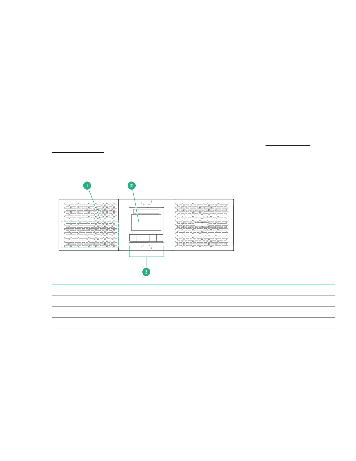
Front panel components
Item Description
1 Battery compartment
2 LED display
3 Control buttons
Component identification 5
Page 6
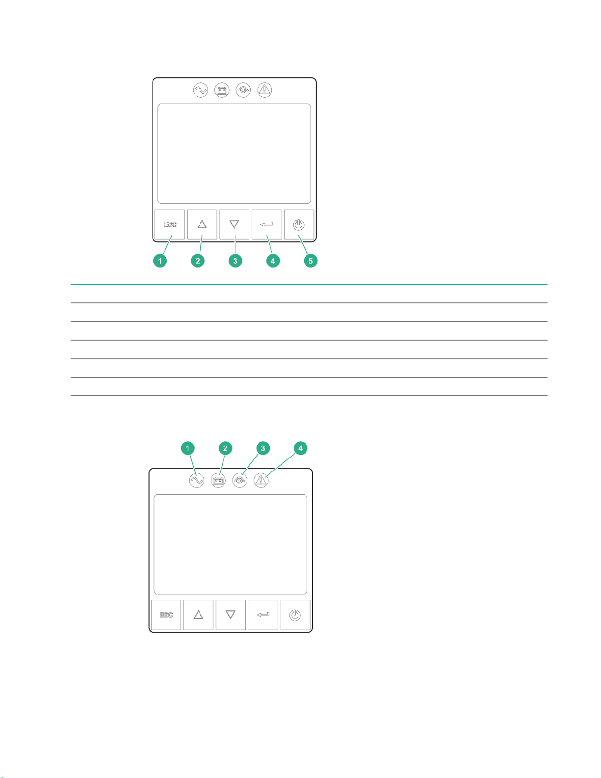
UPS front panel controls
Item Description
1 Escape button
2 Up button
3 Down button
4 Enter button
5 Power button
Front panel LEDs
6 Component identification
Page 7
Item Indicator Status Description
1 Online mode On The UPS is operating normally online or in high efficiency
2 Battery mode On The UPS is on battery mode.
3 Bypass mode On The UPS is in bypass mode.
4 Fault On The UPS has an active alarm or fault. For more
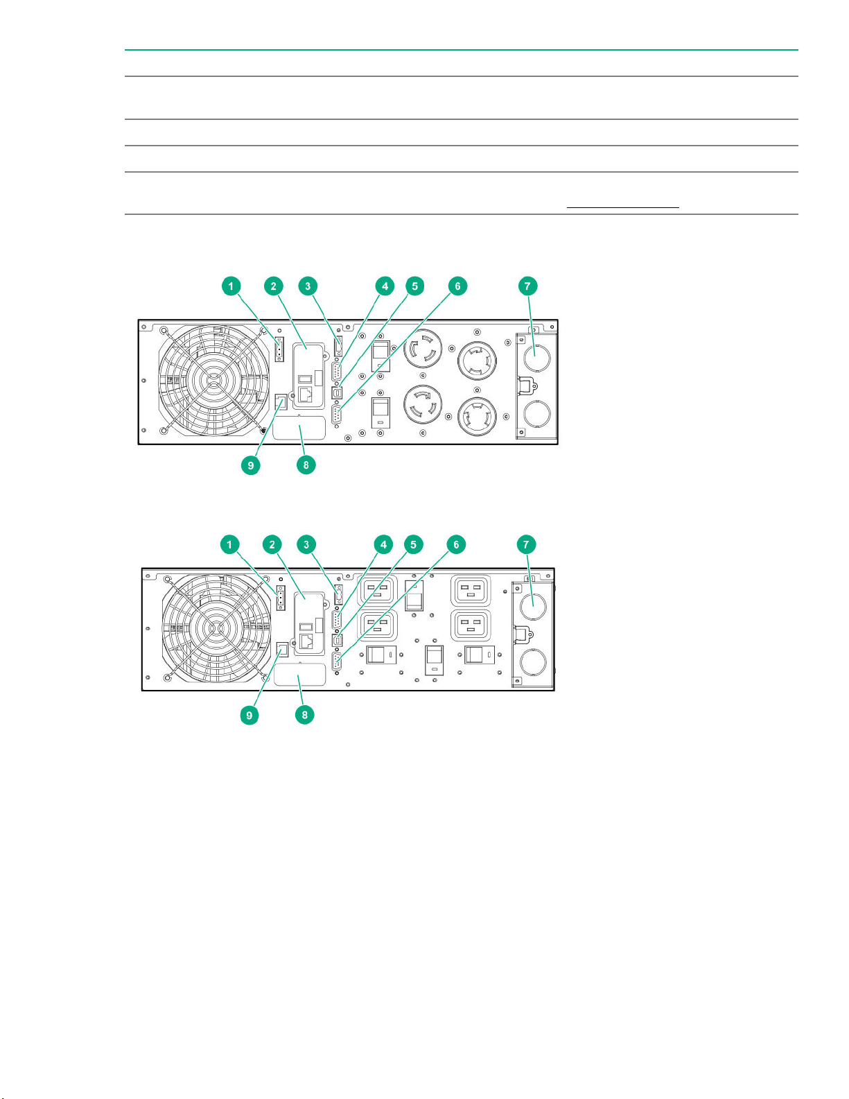
Rear panel components
mode.
information, see the Troubleshooting section.
Figure 1: G2 R5000 4 out NA/JPN model
Figure 2: G2 R5000 5 out NA/JPN model
Component identification 7
Page 8

Figure 3: G2 R6000 INTL model
Item Description
1 Remote Power Off (RPO) terminal block
2 1GB UPS Network Management Module
3 Remote On/Off (ROO) terminal block
4 Dry contacts communications port
5 USB communications port
NOTE: This port is used for UPS firmware updates. For more information, see USB
communications port.
6 Serial communications port
7 Power I/O interface
8 ERM to UPS connection
9 Automatic battery recognition port (ERM)
8 Component identification
Page 9
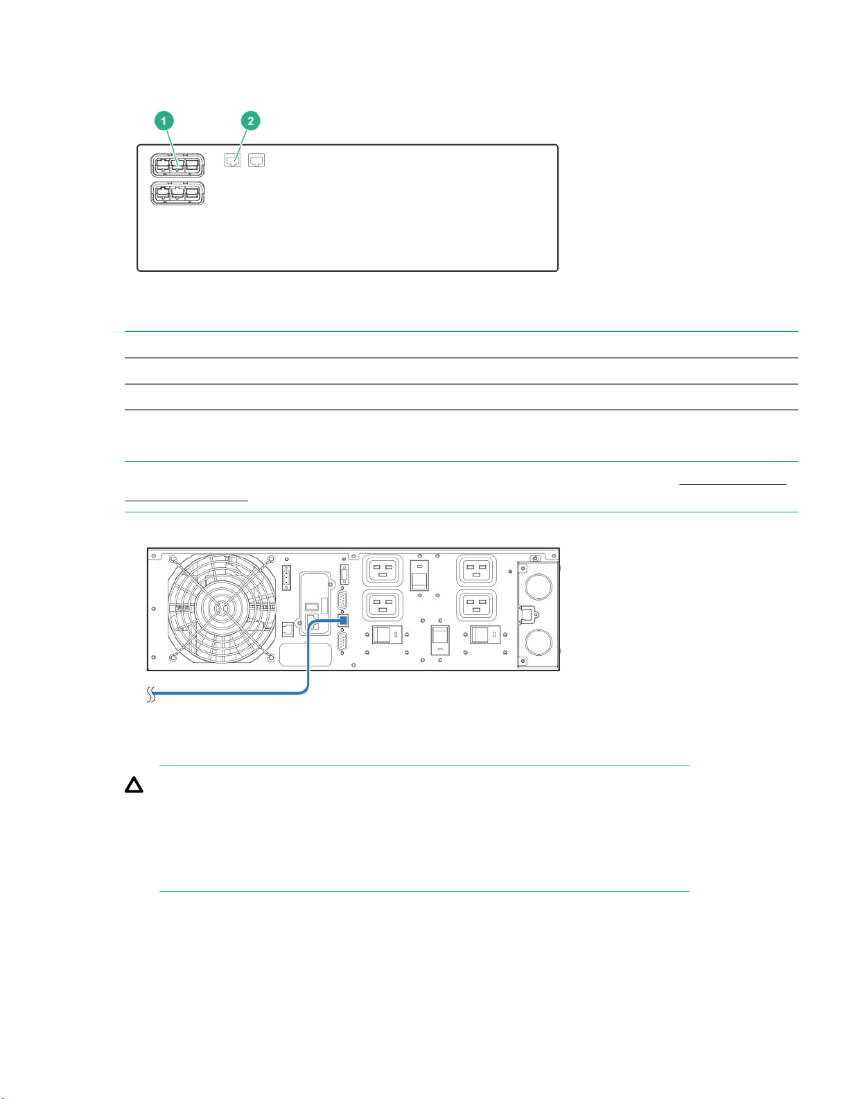
ERM rear panel components
Item Description
1 ERM to UPS connector
2 ERM recognition port
USB communications port
NOTE: This port is only used for firmware upgrades. To update the UPS firmware, see the Hewlett Packard
Enterprise website.
Dry contact port
CAUTION: Before using the dry contact port, the following cautions must be observed:
• The relay output contacts cannot be connected to any utility circuits.
• Reinforced insulation to the utility is required.
• The relay output contacts have a maximum rating of 250VAC/5A.
The UPS has four relay outputs. Each relay output is available with either an open or closed contact.
Component identification 9
Page 10
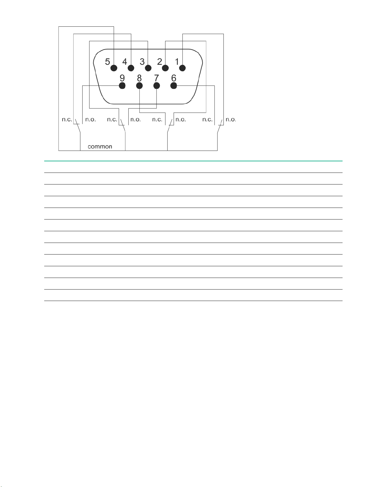
ROO
Pin Description
1 Not on bypass
2 Load not protected
3 Not low battery
4 Not on battery
5 User common
6 On bypass
7 Low battery
8 Load protected
9 On battery
n.o. Contact normally open
n.o. Contact normally closed
ROO allows remote action of the power button to switch the UPS on and off.
• When the contact changes from open to closed, the UPS is switched-on (or stays On).
• When the contact changes from closed to open, the UPS is powered off (or stays Off).
10 Component identification
Page 11
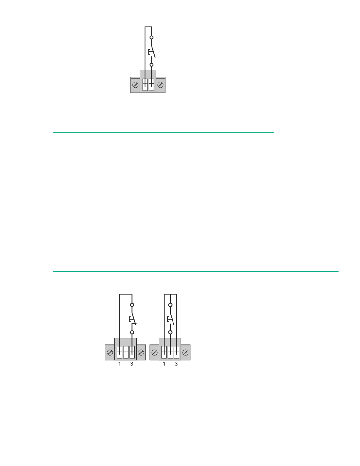
Figure 4: This figure displays a normally open contact.
NOTE: The on/off control using the power button has priority over the remote control.
RPO port
RPO is used to shut down the UPS remotely. This feature is primarily used for remotely powering down the
UPS if there is an emergency. When RPO is activated, the UPS shuts down the output and all its power
converters immediately. The UPS remains on to alarm the fault.
The RPO circuit is an IEC 60950 safety extra low voltage (SELV) circuit. This circuit must be separated from
any hazardous voltage circuits by reinforced insulation. The RPO must also meet the following requirements:
• The RPO cannot be connected to any utility connected circuits. Reinforced insulation to the utility is
required. The RPO switch must have a minimum rating of 27 Vdc and 20 mA and be a dedicated latchingtype switch not tied into any other circuit. The RPO signal must remain active for at least 250 ms for proper
operation.
• To ensure that the UPS stops supplying power to the load during any mode of operation, the input power
must be disconnected from the UPS when the RPO function is activated.
NOTE: Leave the RPO connector installed in the RPO port on the UPS even if the RPO function is not
needed.
The following images illustrate the RPO connections.
Figure 5: Internal power supply
Component identification 11
Page 12

Figure 6: External power supply
12 Component identification
Page 13
Installation
Precautions
Save these instructions. This document contains important safety instructions that must be followed during
installation, operation, and maintenance of the UPS and batteries.
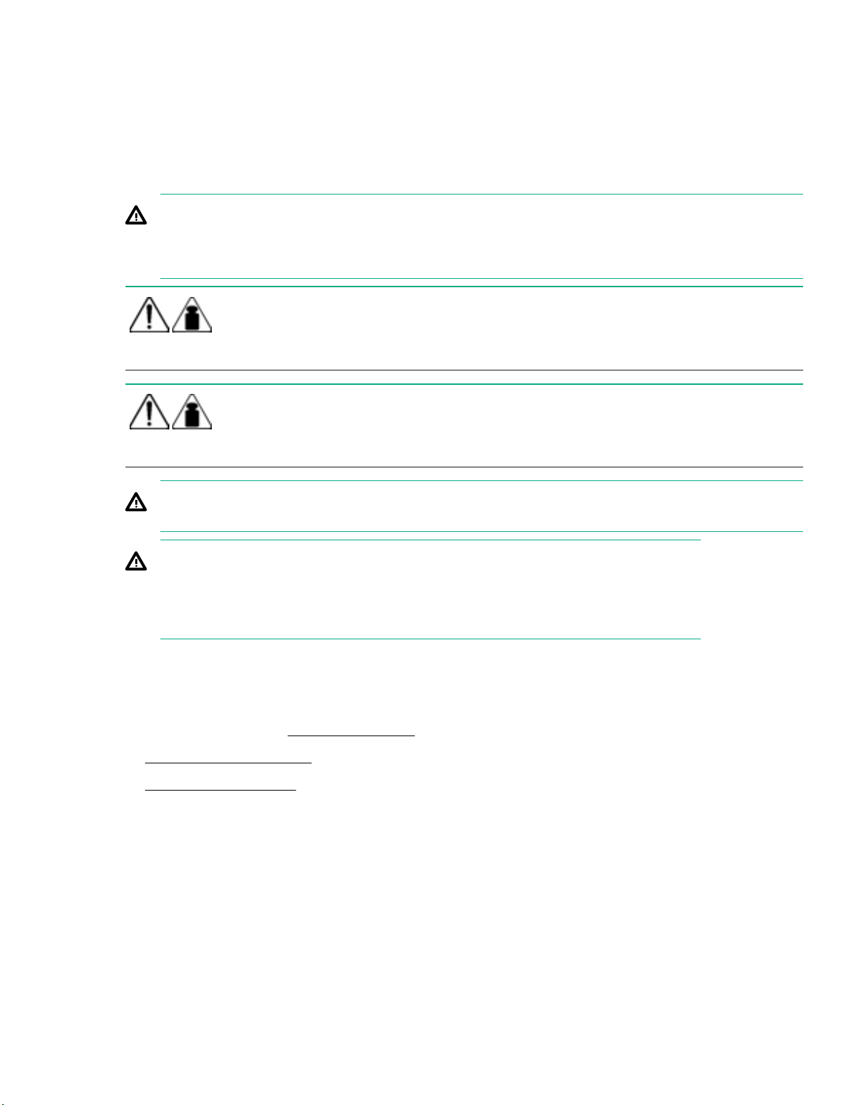
WARNING: A risk of personal injury from electric shock and hazardous energy levels exists. The
installation of options and routine maintenance and service of this product must be performed by
individuals who are knowledgeable about the procedures, precautions, and hazards associated with AC
power products.
48 106
68 150
This symbol indicates that the UPS exceeds the recommended weight for one
individual to handle safely.
This symbol indicates that the ERM exceeds the recommended weight for one
individual to handle safely.
WARNING: To reduce the risk of personal injury or damage to the equipment, observe local
occupational health and safety requirements and guidelines for manual material handling.
WARNING: To prevent personal injury from earth conductor leakage current:
• Do not operate the UPS while disconnected from the utility power source.
• Disconnect load devices before disconnecting the UPS from the utility power source.
Preparing to install the hardware
Before installing the hardware:
1. Be sure the necessary tools and materials are available.
2. Select an installation site.
3. Prepare the equipment for installation in the rack.
Tools and materials
The following tools are required for installation:
Phillips screwdriver
The following items are supplied with the UPS:
Installation 13
Page 14

• Screws
• Washers
Selecting a site
WARNING: To prevent fire or electric shock, install the unit in a temperature- and humidity-controlled
indoor environment, free of conductive contaminants.
When selecting a site, consider the following factors:
• Elevated operating ambient temperature—If the equipment is installed in a closed or multiunit rack
assembly, the operating ambient temperature of the rack environment might be greater than room ambient
temperature. Install the equipment in an environment compatible with the operating temperature. For more
information, see Environmental specifications.
• Reduced air flow—In the rack, the rate of air flow required for safe operation of the equipment must not be
compromised.
• Circuit overloading—Consideration must be given to the connection of the equipment to the supply circuit
and the effect that overloading of the circuits might have on overcurrent protection and supply wiring.
Appropriate consideration of equipment nameplate ratings must be used when addressing this concern.
• Reliable earthing—Reliable earthing of rack-mounted equipment must be maintained. Particular attention
must be given to supply connections other than direct connections to the branch circuit, such as the use of
power strips.
• Electrical requirements—All models require a dedicated (unshared) branch circuit, suitably rated for the
specific UPS as stated in the
Preparing the equipment
Procedure
1. Check the battery recharge date specified on the label that is affixed to the shipping carton.
IMPORTANT: Do not use the battery if the recharge date has passed. If the date on the battery
recharge date label has passed without the battery being recharged, contact an HPE authorized
service representative for directions.
2. Transport the packaged unit to its installation location.
3. Unpack the equipment near the rack where the unit will be assembled.
CAUTION: Always plan the rack installation so that the heaviest item is on the bottom of the rack.
Install the heaviest item first, and continue to populate the rack from the bottom to the top.
UPS input specifications.
14 Installation
Page 15

Installing the mounting rails
WARNING: To reduce the risk of personal injury or damage to the equipment, be sure that:
• The leveling feet are extended to the floor.
• The full weight of the rack rests on the leveling feet.
• If it is a single-rack installation, the stabilizing feet are attached to the rack.
• The racks are coupled together in multiple-rack installations.
• Only one component is extended at a time. A rack may become unstable if more than one
component is extended for any reason.
Procedure
1. Extend the brackets to the appropriate length.
2. Insert screws through the rack into the mounting rail and the front and back of each mounting bracket.
Installing the UPS
Before installing the UPS, review and observe all warnings in Precautions.
WARNING: A risk of personal injury or damage to the equipment exists. Uneven loading of equipment in
the rack might cause the rack to become unstable. Install the heavier components first, and then
continue to populate the rack from the bottom to the top.
Procedure
1. Install the mounting rails.
2. With one person on each side of the carton, lift the chassis and lower it to the floor in front of the rack.
3. Install the mounting ears on the chassis using the screws provided.
Installation 15
Page 16

4. With one person on each side, lift the chassis to rail level and slide the chassis on the mounting rails.
5. Attach the chassis to the rack using the supplied screws.
Connecting the battery
Procedure
1. Remove the bezel from the front of the UPS.
2. Remove the two screws.
16 Installation
Page 17

3. Press the bezel to the right, and then open the front of the UPS.
4. Connect the battery cables.
Installation 17
Page 18

Connecting the serial communications port
CAUTION: Use only the computer interface cable supplied with the UPS to connect the communications
port to the host computer.
IMPORTANT: Power protector software requires the communications port to be appropriately cabled to
the host computer.
NOTE: This port is only used for firmware upgrades. To update the UPS firmware, see the Hewlett Packard
Enterprise website.
Connecting the RPO port
WARNING: To meet the requirements stated in NEC (NFPA 70) Articles 645-10 and 645-11, a UPS
installed in a computer equipment room must be connected to an RPO circuit.
IMPORTANT: The remote switch must be in the Off (open) position to enable power to the output
receptacles.
NOTE: Wire the connector block using stranded, nonshielded wire (AWG #22 - #18, or equivalent).
Separate wire pairs are attached to a single, normally open contact in a parallel connection. Hewlett Packard
Enterprise recommends using different colors for the positive and negative wires.
If a connector becomes disconnected and is reconnected with reversed polarity, an RPO is initiated. To avoid
RPO port disconnect:
18 Installation
Page 19

• Minimize wire strain while connecting the RPO port.
• Avoid allowing the wires to hang in the rear of the UPS.
• Use tie wraps and tie wrap blocks to secure the wires tightly to the rack and the rear of the UPS.
For more information about the RPO port, see RPO port.
Connecting the ground bonding cable
The ground bonding screw is provided as an attachment point for conductors. Use a ground bonding cable if
the rack contains any conductors for the purpose of functional grounding or bonding of ungrounded metal
parts.
Connecting the UPS to utility power
WARNING: To prevent injury from electric shock or damage to the equipment:
• Plug the input line cord into a grounded (earthed) electrical outlet that is installed near the equipment and
is easily accessible.
• Do not disable the grounding plug on the input line cord. The grounding plug is an important safety feature.
• Do not use extension cords.
Connect the UPS to a grounded utility power outlet. When the UPS is plugged in, it automatically enters
Standby mode and begins charging the batteries.
Hard wiring the UPS to utility power
The following list are installation requirements for hard wiring the UPS to utility power.
• Recommended upstream protection
Installation 19
Page 20

UPS power rating Upstream circuit breaker
5000VA D curve—30A
6000VA D curve—32A
• Recommended cable cross-sections
Terminal position Wire function Terminal wire size
L1 Phase 4-16mm 1(12-6AWG)6mm1 (10AWG)
N (L2) Neutral (phase) 10mm1 (8AWG)
Ground
1
Copper wire, solid, or stranded.
Connecting the Input/Output
WARNING: Hewlett Packard Enterprise recommends that this connection is made only by a licensed
electrician.
rating
Minimum input
sire size
105°C (221°F)
75°C (167°F)
Tightening torque
10lb in/1.13 Nm
20 Installation
Page 21

Prerequisites
• Make sure that the upstream protection device is open.
• Make sure that the ground wire is connected.
Procedure
1. Remove the terminal block cover by loosening the screw.
2. Insert the AC cable through the cable gland.
3. Connect the three AC utility power conductors to the AC input terminal block
4. Insert the output cable through the cable gland.
5. Connect the three load conductors to the output terminal block.
6. Replace the terminal block cover, and then tighten the screw.
7. Tighten the cable glands.
Connecting devices to the UPS
CAUTION: Do not plug laser printers into the UPS output receptacles. The instantaneous current drawn
by this type of printer can overload the UPS.
The UPS is intended to power IT equipment only.
Before connecting devices:
• Verify that the UPS will not overload by checking that the ratings of the devices do not exceed the UPS
capacity.
• Evenly distribute connected devices to all circuit breakers. For the maximum current rating for each
receptacle, see UPS output specifications.
After verifying that the UPS will not overload:
Procedure
1. Turn on the circuit breakers for load segments 1 and 2.
2. Connect the device power cords to the appropriate output receptacles on the rear panel of the UPS.
To provide additional receptacles, plug a PDU or other device into the high current, large output receptacle.
The large output receptacle is part of load segment 1 and can be turned off and on using Power protector
software.
Charging the UPS batteries
The UPS can be put into service immediately upon installation; however, new UPS batteries require charging
before full runtime is available. Make sure to check the battery charge status after initially powering on the
UPS.
With the UPS in Standby mode, allow the batteries to charge before putting the UPS into full service.
Installation 21
Page 22

IMPORTANT: When the UPS is initially installed, the batteries may not be fully charged. Hewlett
Packard Enterprise recommends that the batteries charge for at least 24 hours before supplying backup
power to devices to ensure that full battery runtime is available.
Battery test
There are two types of battery tests:
Automated
Manual—through either the front panel or the SHUT command.
IMPORTANT: UPS on battery mode, LCD, LED, and dry contacts must not be active during the
discharge test.
Battery test conditions
To perform the battery test, all the following conditions must be met. If these conditions are not met, the test
status is listed as "test canceled".
• UPS mode must be either AC (online) or HE (high efficiency).
If the UPS is in HE mode, the UPS automatically transfers to AC mode, and then starts the test. After the
test is complete, the UPS automatically transfers back from AC mode to HE mode.
• Load must be at 10% of the rated capacity or greater.
• Battery capacity must be greater than or equal to 80% charged.
• There is no running alarm, excepted battery fault.
• Load level has not varied by more than +/- 10% percent from the initial load level.
Automatic battery quick test
The automatic battery quick test is conducted when the UPS is in charger float mode.
• A quick test is scheduled every 60 seconds.
• The battery is disconnected from the charger for 2 seconds, and then battery voltage is measured.
Automatic battery full test
ABM mode
• The automated battery test (enabled by default) is run in float mode, and the test starting time = 1.5 x t
charge + 24 hours.
• After the test, the ABM charge cycle continues on float mode for another 24 hours.
Constant charge mode
The battery test is scheduled every day, week (default), or month.
In any mode, a battery test is scheduled 10 seconds after every UPS powers up in online mode. The test
starting time is when the output is powered on. When the UPS powers up in online mode, the battery test
mimics a manual test.
22 Installation
Page 23

• In ABM mode, the ABM cycle is restarted after the test is complete.
• In constant charge mode, the charging phase is restarted after the test is complete.
Manual battery full test
The manual battery test is run immediately, even if the UPS is operating in ABM mode, and no test is
postponed or scheduled to run in float mode.
• ABM mode—the ABM cycle is stopped, the test is performed, and then the ABM cycle is restarted after the
test is complete.
• Constant charge mode—The charging phase is restarted after the test is complete.
Starting power to the load
Start power to the load by placing the UPS in Operate mode.
IMPORTANT: AC power must be available the first time the UPS is started.
Installing the ERM
Before installing the ERM, review and observe all warnings in Precautions.
WARNING: A risk of personal injury or damage to the equipment exists. Uneven loading of equipment in
the rack might cause the rack to become unstable. Install the heavier components first, and then
continue to populate the rack from the bottom to the top.
Procedure
1. Install the mounting rails.
2. With one person on each side of the carton, lift the chassis and lower it to the floor in front of the rack.
3. Install the mounting ears on the chassis using the screws provided.
Installation 23
Page 24

4. With one person on each side, lift the chassis to rail level and slide the chassis on the mounting rails.
5. Attach the chassis to the rack using the supplied screws.
Connecting the ERM to the UPS
Connect both ends of the split ERM cable to the ERM connectors on the UPS rear panel. To install additional
ERMs, connect both ends of the split ERM cable from the next ERM into the connectors on the rear panel of
the previous ERM. Up to four ERM units can be connected.
Charging the ERM batteries
Connect the UPS to a grounded utility power outlet. When the UPS is plugged in, it automatically enters
Standby mode and begins charging the ERM batteries. With the UPS in Standby mode, allow the ERM
batteries to charge before putting the UPS into service.
IMPORTANT: When the ERM is initially installed, the batteries may not be fully charged. Hewlett
Packard Enterprise recommends that the batteries charge for at least 24 hours before supplying backup
power to devices to ensure that full battery runtime is available.
IMPORTANT: To verify the attached ERMs are recognized, confirm the number of installed ERMs using
the UPS front panel control through the UPS Status Menu.
24 Installation
Page 25

Operations
Modes of operation
The UPS has four modes of operation:
Standby mode
•
• Online mode
• Battery mode
• Bypass mode
Standby mode
• No power is available at the UPS output receptacles.
• The UPS charges the batteries as necessary.
The UPS can be placed in Standby mode when the UPS is in Online mode.
To place the UPS in Standby mode, press and hold the Power button. Power to the load ceases.
IMPORTANT: While in Standby mode, the UPS maintains the charge on the batteries, but no power is
available at the output receptacles. The UPS remains in Standby mode until an alternate mode is
selected or until utility power is removed.
Online mode
• Power is available at the UPS receptacles.
• The UPS charges the batteries as necessary.
The UPS can be placed in Operate mode if either of the following conditions apply:
• The UPS is powered on and in Standby mode.
• The UPS is powered off and no utility power is available.
To place the UPS in Operate mode, press and hold the Power button.
Battery mode
• A utility failure has occured and the UPS is operating on battery power.
• The UPS is powering the equipment with battery power.
• Prepare the equipment for shutdown.
Bypass mode
The UPS automatically enters Auto-Bypass mode when one of the following conditions occurs:
Operations 25
Page 26

• Extended overload
• Over temperature
• Output short
• Hardware failure
Configuring the UPS
Use the UPS front panel controls to configure the UPS.
IMPORTANT: The output voltage of the UPS must be set to the same nominal voltage as the facility
input. Failure to do so will cause the UPS to buck or boost constantly to maintain the output voltage.
Changing the language
Procedure
1. Press the Enter button to activate the menu options.
2. Press the down arrow button until the Settings menu appears on the LCD menu screen.
3. Press the Enter button.
4. Press the down arrow button until the Local settings menu appears on the LCD menu screen.
5. Press the Enter button.
6. Press the down arrow button until the Language menu appears on the LCD menu screen.
7. Press the Enter button.
8. Press and hold the Enter button to change the language on the UPS.
Changing display functions
The control panel automatically dims after a long period of inactivity. Press any button to restore the screen.
Press the Enter button to activate the menu options. Use the up and down arrow buttons to scroll through the
menu structure. Press the Enter button to enter a submenu or to select an option. Press the ESC button to
cancel or return to the previous menu.
Menu map for display functions
Main menu Submenu Display information or menu function
Measurements — Load, Input/Bypass voltage, Output/Efficiency voltage, Battery
Control Go to Bypass Transfers the UPS on Bypass mode
Start battery test Starts a manual battery test
percentage, Average power usage, Cumulative power usage
26 Operations
Reset fault state Clears active fault
Restore factory
set
Returns all settings to original values
Table Continued
Page 27

Main menu Submenu Display information or menu function
Reset average
power
Reset cumul.
power
Dry contacts test Tests dry contact relay outputs
Settings Local settings Sets product general parameters
In/Out settings Sets output parameters
On/Off settings Sets on/off conditions
Battery settings Sets battery configuration
Event log Event filter Selects faults, alarms, and events to display
Event list Displays the events stored
Reset event list Clears events
Fault log Fault list Displays the faults stored
Reset fault list Clears faults
Identification — Product type, serial number, UPS firmware, communication card IPv6,
Register
product
— Links to the HPE registration website
Clears average power usage measurement
Clears cumulated power usage measurement
communication card MAC, detected accessories
Verifying the RPO port connection
NOTE: While testing, operate connected equipment in a safe test mode so the effects do not disrupt critical
operations.
Prerequisites
Connect the RPO port.
Procedure
1. Initiate an RPO by closing the RPO contact.
2. Verify proper connection of the RPO port.
a. Power up the UPS by pressing the Power button.
b. Disconnect the RPO port.
c. Reconnect the RPO port.
d. Verify that the UPS remains in Online mode.
Operations 27
Page 28

Powering down the UPS
1. Shut down all load devices.
2. Switch the load segment circuit breakers the OFF position.
3. Press and hold the Power button for 3 seconds. Power is removed from the load segments and the
ON/OFF button blinks.
28 Operations
Page 29

Power protector
Power protector software
The HPE 1GB UPS Management Module and the HPE Power Protector software ensures maximum power
reliability of computer systems through comprehensive control of UPSs. The easy-to-use browser interface
enables novice users to configure and manage power protection settings. To download the latest version of
HPE Power Manager software, see the
NOTE: Although the HPE 1GB UPS Management Module ships with the UPS, the HPE Power Protector
Client is the primary software for the servers.
NOTE: To install and configure the software, see the software user guide. The software user guide is
available for download from the Hewlett Packard Enterprise website.
HPE Power Protector has the following features:
• Does not require complex management systems, which simplify deployment, configuration, and
management of UPS-protected environments.
• Manages a graceful shutdown of attached devices during utility power failures.
• Prioritizes the timing of attached load device shutdowns.
• Shuts down and reboots any UPS and attached load devices based on a user-specified schedule.
Hewlett Packard Enterprise website.
• Customizes alert generation with modifiable dialog boxes, command execution, and email and broadcast
messages.
• Monitors the status of the UPS and reports alarms.
• Displays a power log for analysis.
• Manages independent UPS load segments to provide separate power control of attached load devices.
• Delays reboot by load segment after a power outage to sequence the startup of system components.
Power protector 29
Page 30

Maintenance
Replacing the UPS
Procedure
1. Power down all attached load devices.
2. Power down the UPS.
3. Unplug the UPS power cord.
4. Disconnect all cabling.
5. Remove the screws securing the UPS to the rack.
6. Remove the UPS from the rack.
To replace the component, reverse the removal procedure.
Replacing the ERM
Procedure
1. Disconnect all ERM cabling.
2. Remove the screws securing the ERM to the rack.
3. Remove the ERM from the rack.
To replace the component, reverse the removal procedure.
Updating the UPS firmware
To update the UPS firmware, see the Hewlett Packard Enterprise website.
30 Maintenance
Page 31

Troubleshooting
Bypass mode
Symptom
LED is on.
Cause
• An overload or a fault has occurred.
• A command has been received and the UPS is in Bypass mode.
Action
1. Equipment is powered but not protected by the UPS.
2. Check one of the following alarms.
• Overtemperature
• Overload
• UPS failure
Battery low
Symptom
LED is on, one beep for every three seconds.
Cause
The UPS is in Battery mode and the battery is running low.
Action
1. The warning is approximate, and the actual time to shutdown may vary significantly.
2. Depending on the UPS load and number of ERMs, the battery low warning might occur before the
batteries reach 20% capacity.
No battery
Symptom
LED is on, continuous beep.
Cause
The batteries are disconnected.
Troubleshooting 31
Page 32

Action
1. Verify that all batteries are properly connected.
2. If condition persists, contact your service representative.
Battery fault
Symptom
LED is on, continuous beep.
Cause
• The battery test failed due to bad or disconnected batteries.
• The battery minimum voltage is reached and the UPS is in ABM cycling mode.
Action
1. Verify that all batteries are properly connected.
2. Start a new battery test.
If condition persists, contact your service representative.
Backup time
Symptom
The UPS does not provide the expected backup time.
Cause
The batteries need charging or service.
Action
1. Apply utility power for 48 hours to charge the batteries.
2. If condition persists, contact your service representative.
Bypass mode
Symptom
LED is on.
Cause
• An overload or a fault has occurred.
• A command has been received and the UPS is in Bypass mode.
32 Troubleshooting
Page 33

Action
1. Equipment is powered but not protected by the UPS.
2. Check one of the following alarms.
• Overtemperature
• Overload
• UPS failure
Power overload
Symptom
LED is on, beep is continuous.
Cause
Power requirements exceed the UPS capacity.
Action
1. Remove some of the equipment from the UPS
2. The UPS continues to operate, but may switch to Bypass mode or shut down if the load increases.
3. The alarm resets when the condition becomes inactive.
UPS overtemperature
Symptom
LED is on, one beep every three seconds.
Cause
The UPS internal temperature is too high or a fan has failed. At the warning level, the UPS generates the
alarm but remains in the current operating state. If the temperature rises another 10ºC (50ºF), the UPS
transfers to Bypass mode or shuts down if Bypass is unusable.
Action
1. If the UPS transferred to Bypass mode, the UPS will return to normal operation when the temperature
drops to 5ºC (41ºF) below the warning level.
If the condition persists, shut down the UPS.
2. Clear vents and remove any heat sources. Allow the UPS to cool. Ensure the airflow around the UPS is
not restricted.
3. Restart the UPS.
4. If the condition continues to persist, contact your service representative.
Troubleshooting 33
Page 34

UPS does not start
Symptom
The UPS does not power up.
Solution 1
Cause
The input source is not connected correctly.
Action
Check the input connections.
Solution 2
Cause
The RPO switch is active or the RPO connector is missing.
Action
If the UPS status menu displays the "Remote Power Off" notice, inactive the RPO input.
I/O bad wiring
Symptom
I/O LED is on and there is a continuous beep.
Cause
I/O cables are not connected to the correct terminal blocks.
Action
Correctly connect the I/O cables.
34 Troubleshooting
Page 35

Specifications
UPS physical specifications
Parameter Value
Height 13.0cm (5.1in)
Depth 72.13cm (28.4in)
Width 43.9cm (17.3in)
Weight 48kg (106lb)
ERM physical specifications
Parameter Value
Height 13.0cm (5.1in)
Depth 72.13cm (28.4in)
Width 43.9cm (17.3in)
Weight 68kg (150lb)
UPS input specifications
UPS model Utility voltage
frequency (Hz)
G2 R5000 4out
NA/JPN
G2 R5000 5out
NA/JPN
G2 R6000 INTL 50/60 200/208/220/230/240 32A Nondetachable
50/60 200/208/220/230/240 30A
50/60 200/208/220/230/240 30A Nondetachable
UPS output specifications
UPS model Load segment Output receptacles
G2 R5000 4out
NA/JPN
G2 R5000 5out
NA/JPA
1 2 x L6-20R/2 x L6-30R
1 4 x C19, 1x L6-30R Pigtail
Available settings
utility voltage (VAC)
Branch circuit rating
(A)
Line cord
Nondetachable
power cord with
NEMA L6-30 plug
power cord with
NEMA L6-30 plug
power cord with
IEC60309 3-pin 32A
IP44 plug
G2 R6000 INTL 2 4 x C13/4 x C19, 1x IEC 32A Pigtail
Specifications 35
Page 36

Power protection specifications
UPS model VA Nominal power rating
G2 R5000 5000 4500 200/208/220/230/240
G2 R6000 5000 4500 200/208/220/230/240
G2 R6000 IEC 5200 4600 200/208/220/230/240
Voltage specifications
Configuration setting (VAC) Available nominal output voltage (VAC)
G2 R5000 4out NA/JPN 208V
G2 R5000 5out NA/JPN 208V
G2 R6000 INTL 230V
Output tolerance specifications
Source of power Regulation
Utility power Sync with line ±5% of nominal line frequency
Battery power ±0.5% of auto-selected nominal frequency
Output voltage setting
(W)
Output feature specifications
Feature Specification
Online efficiency 92.8% nominal input voltage
Voltage wave shape Sinewave
Surge-suppression IEC62040-2 C3 4kV L-PE, 2kV L-L
Noise filtering IEC62040-2 C3
Battery specifications
Feature Specification
Type 12VDC, sealed, maintenance-free, rechargable, valve-regulated, lead-
acid batteries with a 3-year service life at 25ºC (77ºF)
Voltage The battery modules have a battery string voltage of 180 V.
Average battery runtime
Average battery runtimes are approximate and vary depending on connected equipment, configuration,
battery age, temperature, and so on. These estimates are based on the batteries at beginning of life.
36 Specifications
Page 37

Table 1: G2 R5000 battery runtimes
Load % Estimated battery
runtime (minutes)
10 73 245 931
20 42 149 559
40 17 69 250
60 9 39 144
80 5 25 103
100 3 20 80
Runtime with one ERM
(minutes)
Runtime with four
ERMs (minutes)*
Table 2: G2 R6000 battery runtimes
Load % Estimated battery
runtime (minutes)
10 57 202 753
20 34 125 448
40 14 57 194
60 7 32 116
80 5 22 84
Runtime with one ERM
(minutes)
Runtime with four
ERMs (minutes)*
100 3 16 58
Environmental specifications
Feature Specification
Operating temperature 0ºC to 40ºC (32ºF to 104ºF)
Nonoperating
temperature
Relative humidity 0-95% non condensing
Operating altitude Up to 3,000m (9,843ft) above sea level
Nonoperating altitude Up to 10,000m (32,808ft) above sea level
Audible noise Less than 45 dBA, normal operation
• With batteries—0ºC to 40ºC (32ºF to 104ºF)
• Without batteries—-15ºC to 60ºC (5ºF to 140ºF)
RPO port specifications
The RPO port meets the requirements of NFPA Articles 645-10 and 645-11 for a Disconnecting Means.
Specifications 37
Page 38

UPS spare parts
Description Spare part
UPS accessory kit P09826-001
UPS battery P09824-001
ERM P09832-001
ERM accessory kit P10251-001
UPS/ERM CTO mounting shelf with rails P10250-001
number
38 UPS spare parts
Page 39

Electrostatic discharge
Preventing electrostatic discharge
To prevent damaging the system, be aware of the precautions you must follow when setting up the system or
handling parts. A discharge of static electricity from a finger or other conductor may damage system boards or
other static-sensitive devices. This type of damage may reduce the life expectancy of the device.
Procedure
• Avoid hand contact by transporting and storing products in static-safe containers.
• Keep electrostatic-sensitive parts in their containers until they arrive at static-free workstations.
• Place parts on a grounded surface before removing them from their containers.
• Avoid touching pins, leads, or circuitry.
• Always be properly grounded when touching a static-sensitive component or assembly.
Grounding methods to prevent electrostatic discharge
Several methods are used for grounding. Use one or more of the following methods when handling or
installing electrostatic-sensitive parts:
• Use a wrist strap connected by a ground cord to a grounded workstation or computer chassis. Wrist straps
are flexible straps with a minimum of 1 megohm ±10 percent resistance in the ground cords. To provide
proper ground, wear the strap snug against the skin.
• Use heel straps, toe straps, or boot straps at standing workstations. Wear the straps on both feet when
standing on conductive floors or dissipating floor mats.
• Use conductive field service tools.
• Use a portable field service kit with a folding static-dissipating work mat.
If you do not have any of the suggested equipment for proper grounding, have an authorized reseller install
the part.
For more information on static electricity or assistance with product installation, contact the Hewlett Packard
Enterprise Support Center.
Electrostatic discharge 39
Page 40

Websites
General websites
Hewlett Packard Enterprise Information Library
www.hpe.com/info/EIL
Single Point of Connectivity Knowledge (SPOCK) Storage compatibility matrix
www.hpe.com/storage/spock
Storage white papers and analyst reports
www.hpe.com/storage/whitepapers
For additional websites, see Support and other resources.
40 Websites
Page 41

Support and other resources
Accessing Hewlett Packard Enterprise Support
• For live assistance, go to the Contact Hewlett Packard Enterprise Worldwide website:
http://www.hpe.com/info/assistance
• To access documentation and support services, go to the Hewlett Packard Enterprise Support Center
website:
http://www.hpe.com/support/hpesc
Information to collect
• Technical support registration number (if applicable)
• Product name, model or version, and serial number
• Operating system name and version
• Firmware version
• Error messages
• Product-specific reports and logs
• Add-on products or components
• Third-party products or components
Accessing updates
• Some software products provide a mechanism for accessing software updates through the product
interface. Review your product documentation to identify the recommended software update method.
• To download product updates:
Hewlett Packard Enterprise Support Center
www.hpe.com/support/hpesc
Hewlett Packard Enterprise Support Center: Software downloads
www.hpe.com/support/downloads
Software Depot
www.hpe.com/support/softwaredepot
• To subscribe to eNewsletters and alerts:
www.hpe.com/support/e-updates
• To view and update your entitlements, and to link your contracts and warranties with your profile, go to the
Hewlett Packard Enterprise Support Center More Information on Access to Support Materials page:
www.hpe.com/support/AccessToSupportMaterials
IMPORTANT: Access to some updates might require product entitlement when accessed through the
Hewlett Packard Enterprise Support Center. You must have an HPE Passport set up with relevant
entitlements.
Support and other resources 41
Page 42

Customer self repair
Hewlett Packard Enterprise customer self repair (CSR) programs allow you to repair your product. If a CSR
part needs to be replaced, it will be shipped directly to you so that you can install it at your convenience.
Some parts do not qualify for CSR. Your Hewlett Packard Enterprise authorized service provider will
determine whether a repair can be accomplished by CSR.
For more information about CSR, contact your local service provider or go to the CSR website:
http://www.hpe.com/support/selfrepair
Remote support
Remote support is available with supported devices as part of your warranty or contractual support
agreement. It provides intelligent event diagnosis, and automatic, secure submission of hardware event
notifications to Hewlett Packard Enterprise, which will initiate a fast and accurate resolution based on your
product's service level. Hewlett Packard Enterprise strongly recommends that you register your device for
remote support.
If your product includes additional remote support details, use search to locate that information.
Remote support and Proactive Care information
HPE Get Connected
www.hpe.com/services/getconnected
HPE Proactive Care services
www.hpe.com/services/proactivecare
HPE Proactive Care service: Supported products list
www.hpe.com/services/proactivecaresupportedproducts
HPE Proactive Care advanced service: Supported products list
www.hpe.com/services/proactivecareadvancedsupportedproducts
Proactive Care customer information
Proactive Care central
www.hpe.com/services/proactivecarecentral
Proactive Care service activation
www.hpe.com/services/proactivecarecentralgetstarted
Warranty information
To view the warranty information for your product, see the links provided below:
HPE ProLiant and IA-32 Servers and Options
www.hpe.com/support/ProLiantServers-Warranties
HPE Enterprise and Cloudline Servers
www.hpe.com/support/EnterpriseServers-Warranties
HPE Storage Products
www.hpe.com/support/Storage-Warranties
HPE Networking Products
www.hpe.com/support/Networking-Warranties
Regulatory information
To view the regulatory information for your product, view the Safety and Compliance Information for Server,
Storage, Power, Networking, and Rack Products, available at the Hewlett Packard Enterprise Support Center:
42 Support and other resources
Page 43

www.hpe.com/support/Safety-Compliance-EnterpriseProducts
Additional regulatory information
Hewlett Packard Enterprise is committed to providing our customers with information about the chemical
substances in our products as needed to comply with legal requirements such as REACH (Regulation EC No
1907/2006 of the European Parliament and the Council). A chemical information report for this product can be
found at:
www.hpe.com/info/reach
For Hewlett Packard Enterprise product environmental and safety information and compliance data, including
RoHS and REACH, see:
www.hpe.com/info/ecodata
For Hewlett Packard Enterprise environmental information, including company programs, product recycling,
and energy efficiency, see:
www.hpe.com/info/environment
Documentation feedback
Hewlett Packard Enterprise is committed to providing documentation that meets your needs. To help us
improve the documentation, send any errors, suggestions, or comments to Documentation Feedback
(docsfeedback@hpe.com). When submitting your feedback, include the document title, part number, edition,
and publication date located on the front cover of the document. For online help content, include the product
name, product version, help edition, and publication date located on the legal notices page.
Support and other resources 43
 Loading...