

Page 1
FS-8000C
FS-8000CD
FS-8000CN
Color Printer
Operation Guide
Page 2

Caution
NO LIABILITY IS ASSUMED FOR ANY DAMAGE CAUSED BY IMPROPER INSTALLATION.
Legal Restriction on Printing
It may be prohibited to print copyrighted material without permission of the copyright owner. It is prohibited under any
circumstances to print domestic or foreign currencies. Printing other items may be prohibited.
Notice on Software
SOFTWARE USED WITH THIS PRINTER MUST SUPPORT THE PRINTER'S EMULATION MODE. The printer
is factory-set to emulate the PCL 5c. The emulation mode can be changed by following the procedures described in
Chapter 3.
Notice
The information in this manual is subject to change without notification. Additional pages may be inserted in future
editions. The user is asked to excuse any technical inaccuracies or typographical errors in the present edition.
No responsibility is assumed if accidents occur while the user is following the instructions in this manual. No responsibility is assumed for defects in the printer's firmware (contents of its read-only memory).
This manual, any copyrightable subject matter sold or provided with or in connection with the sale of the page printer,
are protected by copyright. All rights are reserved. Copying or other reproduction of all or part of this manual, any
copyrightable subject matter without the prior written consent of Kyocera Corporation is prohibited. Any copies made
of all or part of this manual, any copyrightable subject must contain the same copyright notice as the material from
which the copying is done.
Trademarks and Notices
PRESCRIBE is a registered trademark of Kyocera Corporation. PRESCRIBE, KPDL, and KIR (Kyocera Image
Refinement) are trademarks of Kyocera Corporation.
Hewlett-Packard, PCL, and PJL are registered trademarks of Hewlett-Packard Company. Centronics is a trade name
of Centronics Corporation. PostScript is a registered trademark of Adobe Systems Incorporated. Macintosh is a registered trademark of Apple computer, Inc. Microsoft, Windows, and Windows NT are registered trademarks of Microsoft
Corporation. PowerPC is a trademark of IBM Corporation. Energy Star is the name of a program of the U.S. Environmental Protection Agency. All other company, product, and service names may be trademarks or registered trademarks
of their respective companies.
This Kyocera Mita page printer uses PeerlessPrintXL to implement HP LaserJet-compatible PCL 5c language emulation. PeerlessPrintXL is a trademark of The Peerless Group, Redondo Beach, CA 90278, U.S.A.
This product was developed using the Tornado
This product contains UFST
TM
TM
RealTime Operating System and Tools from Wind River Systems.
and MicroType® from Agfa Corporation.
i
Page 3

IBM Program License Agreement
THE DEVICE YOU HAVE PURCHASED CONTAINS ONE OR MORE SOFTWARE PROGRAMS ("PROGRAMS") WHICH BELONG TO IBM CORPORATION. THIS DOCUMENT DEFINES THE TERMS AND CONDITIONS UNDER WHICH THE SOFTWARE IS LICENSED TO YOU BY IBM. IF YOU DO NOT AGREE WITH
THE TERMS AND CONDITIONS OF THIS LICENSE, YOU MAY RETURN THE DEVICE FOR A FULL
REFUND WITHIN 14 DAYS OF PURCHASE. IF YOU DO NOT SO RETURN THE DEVICE WITHIN THE 14
DAYS, THEN YOU WILL BE ASSUMED TO HAVE AGREED TO THESE TERMS AND CONDITIONS.
The Programs are licensed not sold. IBM, or an authorized IBM dealer grants you a license for the Programs only in
the country where you purchased the Programs. You possess no rights other than those granted you under this license.
The term "Programs" means the original and all whole or partial copies of the original, including modified copies or
portions merged into other programs. IBM retains ownership of the Programs. IBM owns, or has licensed from the
owner, copyrights in the Programs.
1. License
Under this license, you may use the Programs only with the machine on which they are installed and transfer possession
of the Programs and the machine to another party.
If you transfer the Programs, you must transfer a copy of this license and any other documentation to the other party.
Your license is then terminated. The other party automatically agrees to these terms and conditions by first use of the
Program.
You may not:
1) use, copy, modify, merge, or transfer copies of the Program except as provided in this license;
2) reverse assemble or reverse compile the Program; or
3) sublicense, rent, lease, or assign the Program.
2. Limited Warranty
The Programs are provided ‘AS IS.’
THERE ARE NO OTHER WARRANTIES COVERING THE PROGRAMS (OR CONDITIONS), EXPRESS OR
IMPLIED, INCLUDING, BUT NOT LIMITED TO, THE IMPLIED WARRANTIES OF MERCHANTABILITY
AND FITNESS FOR A PARTICULAR PURPOSE.
Some jurisdictions do not allow the exclusion of implied warranties, so the above exclusion may not apply to you.
3. Limitation of Remedies
IBM’s entire liability under this license is the following:
1) For any claim (including fundamental breach), in any form, related in any way to this license, IBM’s liability will
be for actual damages only and will be limited to the greater of:
a) the equivalent of U.S.$25,000 in your local currency; or
b) IBM’s then generally available license fee for the Program
This limitation will not apply to claims for bodily injury or damages to real or tangible personal property for which IBM
is legally liable.
IBM will not be liable for any lost profits, lost savings, or any incidental damages or other economic consequential
damages, even if IBM, or its authorized supplier, has been advised of the possibility of such damages. IBM will not be
liable for any damages claimed by you based on any third party claim. This limitation of remedies also applies to any
developer of Programs supplied to IBM. IBM’s and the developer’s limitations of remedies are not cumulative. Such
developer is an intended beneficiary of this Section.
Some jurisdictions do not allow these limitations or exclusions, so they may not apply to you.
4. General
You may terminate your license at any time. IBM may terminate your license if you fail to comply with the terms and
conditions of this license. In either event, you must destroy all your copies of the Program. You are responsible for
payment of any taxes, including personal property taxes, resulting from this license. Neither party may bring an action,
regardless of form, more than two years a fter the cause of action arose. If you acquired the Program in the United States,
this license is governed by the laws of the State of New York. If you acquired the Program in Canada, this license is
governed by the laws of the Province of Ontario. Otherwise, this license is governed by the laws of the country in which
you acquired the Program.
ii
Page 4

Typeface Trademark Acknowledgement
All resident fonts in this printer are licensed from Agfa Corporation.
Helvetica, Palatino and Times are registered trademarks of Linotype-Hell AG.
ITC Avant Garde Gothic, ITC Bookman, ITC ZapfChancery and ITC Zapf Dingbats are registered trademarks of
International Typeface Corporation.
Agfa Japan License Agreement
1) ‘Software’ shall imply digitally encoded, machine readable, scalable outline data as encoded in a special format
as well as UFST Software.
2) You agree to accept a non-exclusive license to use the Software to reproduce and display weights, styles and
versions of letters, numerals, characters and symbols (‘Typefaces’) solely for your own customary business. Agfa
Japan retains all rights, title and interest to the Software and Typefaces and no rights are granted to you other than
a License to use the Software on the terms expressly set forth in this Agreement.
3) To protect proprietary rights of Agfa Japan, you agree to maintain the Software and other proprietary information
concerning the Typefaces in strict confidence and to establish reasonable procedures regulating access to and use
of the Software and Typefaces.
4) You agree not to duplicate or copy the Software or Typefaces, except that you may make one backup copy.
5) This License shall continue until the last use of the Software and Typefaces, unless sooner terminated. This License
may be terminated by Agfa Japan if you fail to comply with the terms of this License and such failure is not
remedied within thirty (30) days after notice from Agfa Japan. When this License expires or is terminated, you
shall either return to Agfa Japan or destroy all copies of the Software and Typefaces and documentation as
requested.
6) You agree that you will not modify, alter, disassemble, decrypt, reverse engineer or decompile the Software.
7) Agfa Japan warrants that for ninety (90) days after delivery, the Software will perform in accordance with Agfa
Japan-published specifications. Agfa Japan does not warrant that the Software is free from all bugs, errors and
omissions.
THE PARTIES AGREE THAT ALL OTHER WARRANTIES, EXPRESSED OR IMPLIED, INCLUDING
WARRANTIES OF FITNESS FOR A PARTICULAR PURPOSE AND MERCHANTABILITY, ARE
EXCLUDED.
8) Your exclusive remedy and the sole liability of Agfa Japan in connection with the Software and Typefaces is repair
or replacement of defective parts, upon their return to Agfa Japan.
IN NO EVENT WILL AGFA JAPAN BE LIABLE FOR LOST PROFITS, LOST DATA, OR ANY OTHER
INCIDENTAL OR CONSEQUENTIAL DAMAGES, OR ANY DAMAGES CAUSED BY ABUSE OR MISAPPLICATION OF THE SOFTWARE AND TYPE FACES.
9) New York, U.S.A. law governs this Agreement.
10) You shall not sublicense, sell, lease, or otherwise transfer the Software and/or Typefaces without the prior written
consent of Agfa Japan.
11) Use, duplication or disclosure by the Government is subject to restrictions as set forth in the Rights in Technical
Data and Computer Software clause at FAR 252-227-7013, subdivision (b)(3)(ii) or subparagraph (c)(1)(ii), as
appropriate. Further use, duplication or disclosure is subject to restrictions applicable to restricted rights software
as set forth in FAR 52.227-19 (c)(2).
12) YOU ACKNOWLEDGE THAT YOU HAVE READ THIS AGREEMENT, UNDERSTAND IT, AND AGREE
TO BE BOUND BY ITS TERMS AND CONDITIONS. NEITHER PARTY SHALL BE BOUND BY ANY
STATEMENT OR REPRESENTATION NOT CONTAINED IN THIS AGREEMENT. NO CHANGE IN THIS
AGREEMENT IS EFFECTIVE UNLESS WRITTEN AND SIGNED BY PROPERLY AUTHORIZED REPRESENTATIVES OF EACH PARTY.
iii
Page 5

FCC statement (for users in the United States)
This device complies with Part 15 of the FCC Rules. Operation is subject to the following two conditions: (1) This
device may not cause harmful interference, and (2) this device must accept any interference received, including interference that may cause undesired operation.
Note:
This equipment has been tested and found to comply with the limits for a Class B digital device, pursuant to Part 15 of
the FCC Rules. These limits are designed to provide reasonable protection against harmful interference in a residential
installation. This equipment generates, uses, and can radiate radio frequency energy and, if not installed and used in
accordance with the instructions, may cause harmful interference to radio communications. However, there is not
guarantee that interference will not occur in a particular installation. If this equipment does not cause harmful interference to radio or television reception, which can be determined by turning the equipment off and on, the user is encouraged to try to correct the interference by one or more of the following measures:
• Reorient or relocate the receiving antenna.
• Increase the distance between the equipment and the receiver.
• Connect the equipment into an outlet on a circuit different from that used for the receiver.
• Consult the dealer or an experienced radio/TV technician for help.
Changes or modifications not expressly approved by the manufacturer for compliance could void the user's authority
to operate the equipment. Shielded circular cables should be used for interfacing with the computer.
Cautions to the user:
• Any modifications without prior permission of Kyocera may cause harmful interference.
• If any modifications or changes are made to this equipment without prior permission of Kyocera, Kyocera as the
manufacturer does not guarantee the compliance with the FCC Rules.
• The use of equipment that does not comply with the FCC Rules is prohibited.
iv
Page 6
Important Notes for Interface connectors
Be sure to power off the printer before connecting or disconnecting an interface cable. For protection against static
electricity discharge to the printer's internal electronics through the interface connector(s), cover any interface connector that is not in use with the protective cap supplied.
Use shielded interface cables.
Safety information
Laser safety:
This printer is certified as a Class 1 laser product under the U.S. Department of Health and Human Services (DHHS)
Radiation Performance Standard according to the Radiation Control for Health and Safety Act of 1968. This means
that the printer does not produce hazardous laser radiation. Because radiation emitted inside the printer is completely
confined within the protective housings and external covers, the laser beam cannot escape from the printer during any
phase of user operation.
Laser notice:
This printer is certified in the United States to conform to the requirements of DHHS 21 CFR Subchapter for Class I
(1) laser products, and is certified elsewhere as a Class I laser product conforming to the requirements of IEC 825-1.
Cautions:
• Laser radiation will open. DO NOT STARE INTO THE BEAM OR VIEW THE BEAM DIRECTLY WITH
OPTICAL INSTRUMENTS.
• Use of controls or adjustments or performance of procedures other than those specified herein may result in hazardous radiation exposure.
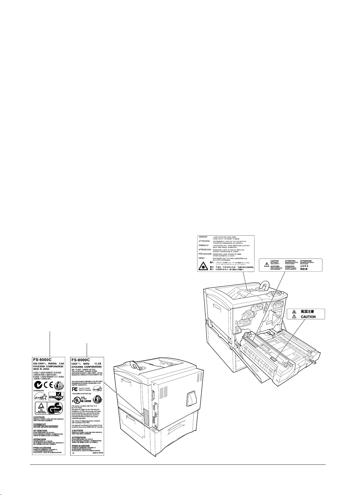
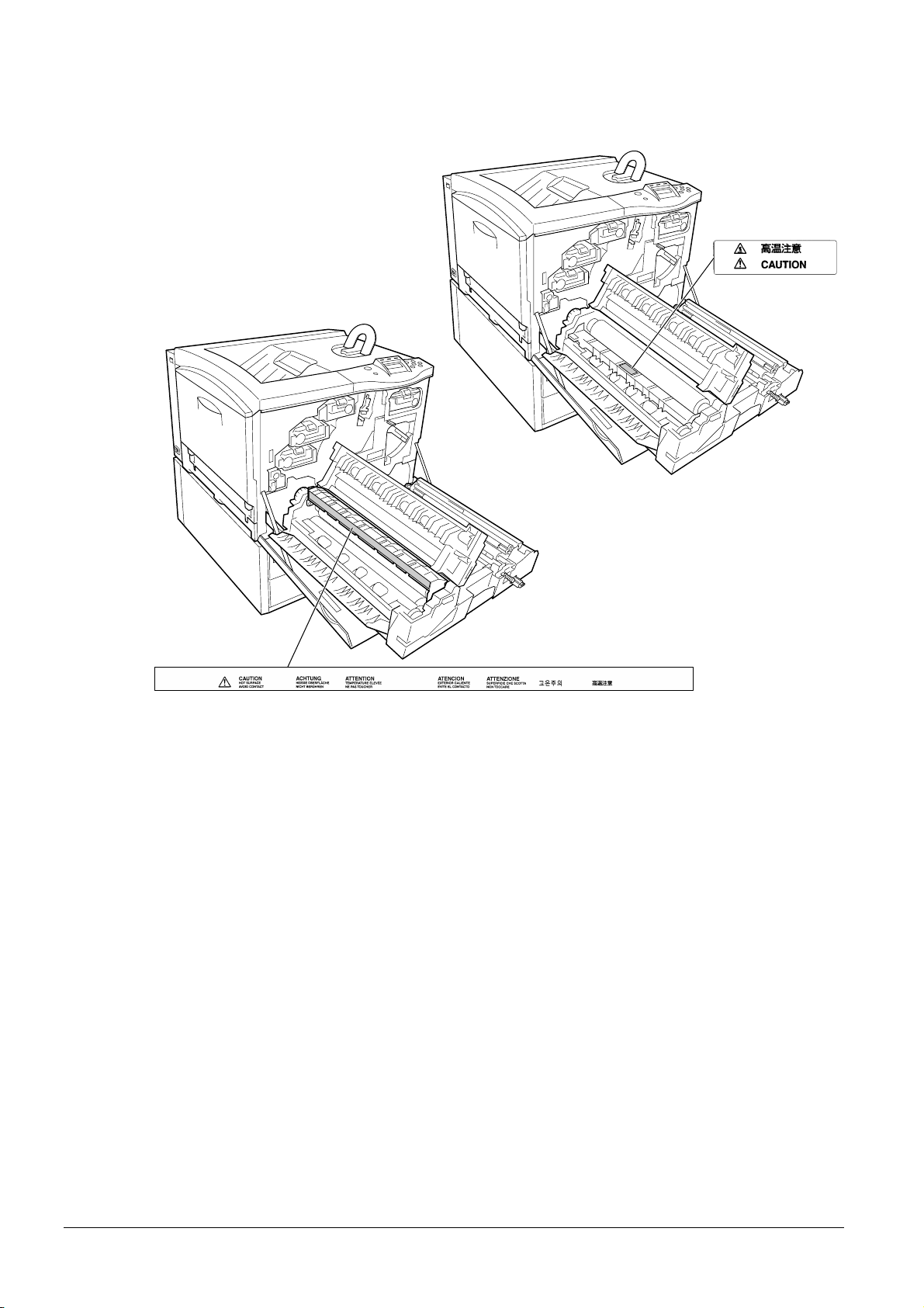
Cautionary Labels
For European and
Asian countries
For U.S.A. and Canada
The printer bears any of the following labels.
Inside
v
Page 7
U.S. CDRH regulations
The Center of Devices and Radiological Health (CDRH) of the U.S. Food and Drug Administration implemented
regulations for laser products on August 2, 1976. These regulations apply to laser products manufactured on and after
August 1, 1976. Compliance is mandatory for products marketed in the United States. A label indicating compliance
with the CDRH regulations must be attached to laser products marketed in the United States.
Ozone concentration
The printers generate ozone gas (O3) which may concentrate in the place of installation and cause an unpleasant smell.
To minimize the concentration of ozone gas to less than 0.1 ppm, we recommend you not to install the printer in a
confined area where ventilation is blocked.
To Prevent Printer from Tipping Over
To prevent the FS-8000C printer from tipping over, the optional CA-31B caster kit must be installed when the printer
is installed with more than one paper feeder or a duplex unit. For detailed information on the CA-31B caster kit, see
page A-11.
vi
Page 8

Declaration of Conformity for U.S.A.
Model name: Color Page Printer FS-8000C
Trade name: Kyocera Mita
Responsible party: Kyocera Mita America, Inc.
Address: 225 Sand Road PO Box 40008 Fairfield, New Jersey 07004-0008, U.S.A.
Telephone: (973) 808-8444
Fax: (973) 882-6000
Contact person for technical matter: Ryozo Kojima
Phone: (973)-882-6019
Manufacturer’s name: Kyocera Corporation, Printer Division
Manufacturer’s address: 2-14-9 Tamagawadai, Setagaya-ku, Tokyo 158-8610, Japan
This device complies with Part 15 of the FCC Rules. Operation is subject to the following two conditions: (1) this
device may not cause harmful interference, and (2) this device must accept any interference received, including interference that may cause undesired operation.
The manufacturer and its merchandising companies retain the following technical documentation in anticipation of the
inspection that may be conducted by the authorities concerned.
User’s instruction that conforms to the applicable specifications.
Technical drawings.
Descriptions of the procedures that guarantee the conformity.
Other technical information.
Kyocera Mita America Inc.
CE Marking Directive
According to Council Directive 89/336/EEC and 73/23/EEC
Manufacturer’s name: Kyocera Corporation, Mie Plant Tamaki Block
Manufacturer’s address: 704-19 Nojino, Tamaki-Cho, Watarai-Gun, Mie-Ken 519-0497, Japan
Declares that the product
Product name: Color Laser Printer
Model number: FS-8000C / FS-8000CN
(as tested with enhancement optional units; Duplex unit PD-30, Paper Feeder PF-30A, Document
Finisher DF-31 etc.)
Conforms to the following product specifications:
EN 55 022: 1998 Class B
EN 61 000-3-2: 1995
EN 61 000-3-3: 1995
EN 55 024: 1998
EN 60 950: 1992+A1+A2+A3+A4+A11
EN 60 825-1: 1994+A11
The manufacturer and its merchandising companies retain the following technical documentation in anticipation of the
inspection that may be conducted by the authorities concerned.
User’s instruction that conforms to the applicable specifications.
Technical drawings.
Descriptions of procedures that guarantee conformity.
Other technical information.
vii
Page 9

Declaration of Conformity for Australia
Manufacturer’s name: Kyocera Corporation, Printer Division
Manufacturer’s address: 2-14-9 Tamagawadai, Setagaya-ku, Tokyo 158-8610, Japan
declares that the product
Product name: Page Printer
Model name: FS-8000C
Description of devices: This Page Printer Model FS-8000C is the 30 ppm (monochrome)/8 ppm (color), A4 size and
utilized plane paper; laser; dry toner; etc. The printer can be equipped with several enhancement optional units as a
paper feeder as PF-30A, a duplex unit as PD-30, a mailbox/sorter as SO-30, IB-21E, etc.
conforms to the following product specifications:
AS/NZS 3548: 1995 (EN 55 022: 1998 Class B)
IEC60950 (EN 60 950: 1992+A1+A2+A3+A4+A11)
IEC60825-1 (EN 60 825-1: 1994+A11)
The manufacturer and its merchandising companies retain the following technical documentation in anticipation of the
inspection that may be conducted by the authorities concerned.
User’s instruction that conforms to the applicable specifications
Technical drawings
Descriptions of procedures that guarantee conformity
Other technical information
The manufacturer has been employed with ISO9001 scheme. JQA and BS have attested the manufacturer.
Kyocera Mita Australia Pty., Ltd.
6-10 Talavera Road, North Ryde, NSW 2113, Australia
Telephone: +61 2-9888-9999
Fax: +61 2-9888-9588
Canadian Department of Communications compliance statement
This Class B digital apparatus complies with Canadian ICES-003.
Avis de conformité aux normes du ministere des Communications du Canada
Cet appareil numérique de la classe B est conforme a la norme NMB-003 du Canada.
ISO 7779
Maschinenlärminformationsverordnung 3. GSGV, 18.01.1991: Der höchste Schalldruckpegel beträgt 70 dB (A) oder
weniger gemäß ISO 7779.
Disclaimer
Kyocera will not be liable to customers or any other person or entity for any loss or damage caused or alleged to be
caused directly or indirectly by equipment sold or furnished by us, including but not limited to, any interruption of
service, loss of business or anticipatory profits, or consequential damages resulting from the use or operation of the
equipment or software.
viii
Page 10
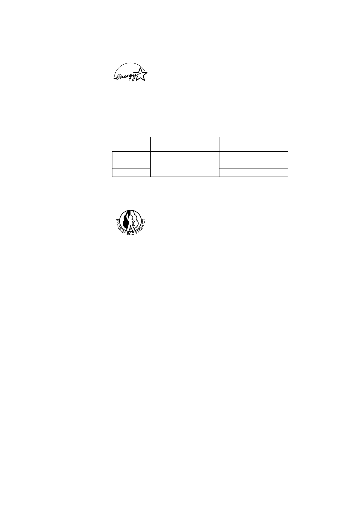
NERGY STAR
E
®
As an E
NERGY STAR
E
NERGY STAR
guidelines for energy efficiency.
The basic objective of the E
Partner, Kyocera Corporation has determined that this product meets the
NERGY STAR
Program is to reduce environmental pollution by
encouraging the manufacture and sale of equipment that uses energy more efficiently.
This printer is equipped with a sleep timer function that conforms with the standards of the
E
NERGY STAR
Program. This function makes it possible to reduce the amount of electrical power consumed by the
printer. For maximum power savings, turn off the printer's power supply when not using the printer for extended periods
of time.
For details on the sleep timer function and printer power consumption, refer to this manual.
Initial settings of the sleep timer function and power saved using the sleep timer function:
Power consumption in
34 W (40 W)
FS-8000C
FS-8000CD
Initial sleep mode setting
30 minutes (30 minutes)
FS-8000CN 37 W (40 W)
( ): ENERGY STAR program guideline
Kyosera ECO-PRODUCT
This product has been developed and manufactured with the express interest of reducing the
impact on the environment.
Using Kyocera's innovative cartridge free techology, Kyocera has created an advanced printing
system that does not require the wasteful replacement and disposal of a cartridge.
sleep mode
ix
Page 11

x
Page 12

Contents
Chapter 1 Introduction
1.1 Features . . . . . . . . . . . . . . . . . . . . . . . . . . . . . . . . . . . . . . . . . . . . . . . . 1-2
1.1.1 General . . . . . . . . . . . . . . . . . . . . . . . . . . . . . . . . . . . . . . . . . . . . . . . . . 1-2
1.1.2 Hardware . . . . . . . . . . . . . . . . . . . . . . . . . . . . . . . . . . . . . . . . . . . . . . . 1-2
1.1.3 Software . . . . . . . . . . . . . . . . . . . . . . . . . . . . . . . . . . . . . . . . . . . . . . . . 1-3
1.1.4 Networking . . . . . . . . . . . . . . . . . . . . . . . . . . . . . . . . . . . . . . . . . . . . . . 1-4
1.2 Parts and Functions . . . . . . . . . . . . . . . . . . . . . . . . . . . . . . . . . . . . . . 1-5
1.2.1 Front . . . . . . . . . . . . . . . . . . . . . . . . . . . . . . . . . . . . . . . . . . . . . . . . . . . 1-5
1.2.2 Internal . . . . . . . . . . . . . . . . . . . . . . . . . . . . . . . . . . . . . . . . . . . . . . . . . 1-7
1.2.3 Rear . . . . . . . . . . . . . . . . . . . . . . . . . . . . . . . . . . . . . . . . . . . . . . . . . . . 1-8
1.3 Clearance . . . . . . . . . . . . . . . . . . . . . . . . . . . . . . . . . . . . . . . . . . . . . . 1-10
Chapter 2 Handling Paper
2.1 General . . . . . . . . . . . . . . . . . . . . . . . . . . . . . . . . . . . . . . . . . . . . . . . . . 2-2
2.1.1 Available paper types . . . . . . . . . . . . . . . . . . . . . . . . . . . . . . . . . . . . . . 2-2
2.1.2 Paper specifications . . . . . . . . . . . . . . . . . . . . . . . . . . . . . . . . . . . . . . . 2-2
2.1.3 Minimum and Maximum Paper Sizes . . . . . . . . . . . . . . . . . . . . . . . . . . 2-3
2.1.4 Recommended Paper . . . . . . . . . . . . . . . . . . . . . . . . . . . . . . . . . . . . . . 2-3
2.2 Selecting the Right Paper . . . . . . . . . . . . . . . . . . . . . . . . . . . . . . . . . 2-4
2.2.1 Guidelines . . . . . . . . . . . . . . . . . . . . . . . . . . . . . . . . . . . . . . . . . . . . . . . 2-4
2.2.2 Paper properties . . . . . . . . . . . . . . . . . . . . . . . . . . . . . . . . . . . . . . . . . . 2-5
2.2.3 Other properties of paper . . . . . . . . . . . . . . . . . . . . . . . . . . . . . . . . . . . 2-7
2.3 Special Paper . . . . . . . . . . . . . . . . . . . . . . . . . . . . . . . . . . . . . . . . . . . 2-8
2.3.1 Selecting the Special Paper . . . . . . . . . . . . . . . . . . . . . . . . . . . . . . . . . 2-8
Chapter 3 Using the Operator Panel
3.1 Understanding the Operator Panel . . . . . . . . . . . . . . . . . . . . . . . . . . 3-2
3.1.1 Message Display . . . . . . . . . . . . . . . . . . . . . . . . . . . . . . . . . . . . . . . . . . 3-2
3.1.2 Indicators in Message Display . . . . . . . . . . . . . . . . . . . . . . . . . . . . . . . 3-3
3.1.3 Keys . . . . . . . . . . . . . . . . . . . . . . . . . . . . . . . . . . . . . . . . . . . . . . . . . . . 3-6
3.2 Using the Menu Selection System . . . . . . . . . . . . . . . . . . . . . . . . . . 3-8
3.2.1 Menu System Road Map . . . . . . . . . . . . . . . . . . . . . . . . . . . . . . . . . . . 3-8
3.3 Menu Map and Status Pages . . . . . . . . . . . . . . . . . . . . . . . . . . . . . . 3-14
3.3.1 Printing a Menu Map . . . . . . . . . . . . . . . . . . . . . . . . . . . . . . . . . . . . . . 3-14
3.3.2 Printing a Status Page . . . . . . . . . . . . . . . . . . . . . . . . . . . . . . . . . . . . 3-16
3.4 e-MPS . . . . . . . . . . . . . . . . . . . . . . . . . . . . . . . . . . . . . . . . . . . . . . . . . 3-20
3.4.1 Using Quick Copy . . . . . . . . . . . . . . . . . . . . . . . . . . . . . . . . . . . . . . . . 3-21
3.4.2 Using Proof-and-Hold . . . . . . . . . . . . . . . . . . . . . . . . . . . . . . . . . . . . . 3-23
3.4.3 Printing a Private Job . . . . . . . . . . . . . . . . . . . . . . . . . . . . . . . . . . . . . 3-25
3.4.4 Storing a Print Job . . . . . . . . . . . . . . . . . . . . . . . . . . . . . . . . . . . . . . . 3-27
3.4.5 Printing a List of Code Jobs . . . . . . . . . . . . . . . . . . . . . . . . . . . . . . . . 3-29
3.4.6 Retrieving Jobs from Virtual Mailbox (VMB) . . . . . . . . . . . . . . . . . . . . 3-30
3.4.7 Changing e-MPS Configuration . . . . . . . . . . . . . . . . . . . . . . . . . . . . . 3-32
3.5 Changing the Interface Parameters . . . . . . . . . . . . . . . . . . . . . . . . 3-38
3.5.1 Changing Parallel Interface Mode . . . . . . . . . . . . . . . . . . . . . . . . . . . . 3-38
3.5.2 Changing Serial Interface Parameters . . . . . . . . . . . . . . . . . . . . . . . . 3-39
3.5.3 Changing Network Interface Parameters . . . . . . . . . . . . . . . . . . . . . . 3-41
3.5.4 Resolving IP Address . . . . . . . . . . . . . . . . . . . . . . . . . . . . . . . . . . . . . 3-43
3.6 Making Default Settings . . . . . . . . . . . . . . . . . . . . . . . . . . . . . . . . . . 3-47
3.6.1 Default Emulation . . . . . . . . . . . . . . . . . . . . . . . . . . . . . . . . . . . . . . . . 3-47
3.6.2 KC-GL Pen Width and Color . . . . . . . . . . . . . . . . . . . . . . . . . . . . . . . . 3-48
3.6.3 Alternative Emulation for KPDL Emulation . . . . . . . . . . . . . . . . . . . . . 3-50
xi
Page 13

3.6.4 Printing KPDL Errors . . . . . . . . . . . . . . . . . . . . . . . . . . . . . . . . . . . . . 3-51
3.6.5 Default Font . . . . . . . . . . . . . . . . . . . . . . . . . . . . . . . . . . . . . . . . . . . . 3-52
3.7 Pagination . . . . . . . . . . . . . . . . . . . . . . . . . . . . . . . . . . . . . . . . . . . . . 3-58
3.7.1 Number of Copies . . . . . . . . . . . . . . . . . . . . . . . . . . . . . . . . . . . . . . . . 3-58
3.7.2 Print Orientation . . . . . . . . . . . . . . . . . . . . . . . . . . . . . . . . . . . . . . . . . 3-59
3.7.3 Page Protect Mode . . . . . . . . . . . . . . . . . . . . . . . . . . . . . . . . . . . . . . . 3-60
3.7.4 Linefeed (LF) Action . . . . . . . . . . . . . . . . . . . . . . . . . . . . . . . . . . . . . . 3-61
3.7.5 Carriage-Return (CR) Action . . . . . . . . . . . . . . . . . . . . . . . . . . . . . . . 3-62
3.8 Setting Print Quality . . . . . . . . . . . . . . . . . . . . . . . . . . . . . . . . . . . . . 3-63
3.8.1 KIR . . . . . . . . . . . . . . . . . . . . . . . . . . . . . . . . . . . . . . . . . . . . . . . . . . . 3-63
3.8.2 EcoPrint . . . . . . . . . . . . . . . . . . . . . . . . . . . . . . . . . . . . . . . . . . . . . . . 3-64
3.8.3 Tone Mode . . . . . . . . . . . . . . . . . . . . . . . . . . . . . . . . . . . . . . . . . . . . . 3-66
3.8.4 Gloss Mode . . . . . . . . . . . . . . . . . . . . . . . . . . . . . . . . . . . . . . . . . . . . 3-67
3.9 Operating the Storage Device . . . . . . . . . . . . . . . . . . . . . . . . . . . . . 3-69
3.9.1 Setting up the RAM Disk . . . . . . . . . . . . . . . . . . . . . . . . . . . . . . . . . . 3-69
3.9.2 Reading/Writing to an Option Storage Device . . . . . . . . . . . . . . . . . . 3-70
3.10 Paper Handling . . . . . . . . . . . . . . . . . . . . . . . . . . . . . . . . . . . . . . . . . 3-79
3.10.1 MP Tray Mode . . . . . . . . . . . . . . . . . . . . . . . . . . . . . . . . . . . . . . . . . . 3-79
3.10.2 Setting MP Tray Paper Size . . . . . . . . . . . . . . . . . . . . . . . . . . . . . . . . 3-80
3.10.3 Setting the MP Tray Paper Type . . . . . . . . . . . . . . . . . . . . . . . . . . . . 3-81
3.10.4 Setting the Cassette Paper Type . . . . . . . . . . . . . . . . . . . . . . . . . . . . 3-82
3.10.5 Selecting the Paper Feed Source . . . . . . . . . . . . . . . . . . . . . . . . . . . . 3-84
3.10.6 Duplex Printing (FS-8000CD) . . . . . . . . . . . . . . . . . . . . . . . . . . . . . . . 3-85
3.10.7 Overriding Difference between A4 and Letter . . . . . . . . . . . . . . . . . . 3-88
3.10.8 Creating Custom Paper Types . . . . . . . . . . . . . . . . . . . . . . . . . . . . . . 3-89
3.10.9 Resetting the Custom Paper Type . . . . . . . . . . . . . . . . . . . . . . . . . . . 3-92
3.10.10Selecting the Output Stack . . . . . . . . . . . . . . . . . . . . . . . . . . . . . . . . . 3-93
3.10.11Selecting the Option Sorter Mode . . . . . . . . . . . . . . . . . . . . . . . . . . . 3-94
3.11 Color Control . . . . . . . . . . . . . . . . . . . . . . . . . . . . . . . . . . . . . . . . . . 3-97
3.11.1 Selecting Monochrome or Color Printing . . . . . . . . . . . . . . . . . . . . . . 3-97
3.11.2 Matching Colors to Monitor (RGB Simulation) . . . . . . . . . . . . . . . . . . 3-98
3.11.3 Using Ink Simulation . . . . . . . . . . . . . . . . . . . . . . . . . . . . . . . . . . . . . . 3-99
3.11.4 Color Calibration . . . . . . . . . . . . . . . . . . . . . . . . . . . . . . . . . . . . . . . . 3-100
3.12 Reading Life Counters . . . . . . . . . . . . . . . . . . . . . . . . . . . . . . . . . . 3-101
3.12.1 Displaying the Total Printed Pages . . . . . . . . . . . . . . . . . . . . . . . . . 3-101
3.12.2 Displaying the Oil Unit Life . . . . . . . . . . . . . . . . . . . . . . . . . . . . . . . . 3-102
3.12.3 Resetting the Toner Counter . . . . . . . . . . . . . . . . . . . . . . . . . . . . . . 3-103
3.13 Other Modes . . . . . . . . . . . . . . . . . . . . . . . . . . . . . . . . . . . . . . . . . . 3-104
3.13.1 Selecting the Message Language . . . . . . . . . . . . . . . . . . . . . . . . . . 3-104
3.13.2 Automatic Form Feed Timeout Setting . . . . . . . . . . . . . . . . . . . . . . . 3-105
3.13.3 Setting the Sleep Timer . . . . . . . . . . . . . . . . . . . . . . . . . . . . . . . . . . 3-106
3.13.4 Received Data Dump . . . . . . . . . . . . . . . . . . . . . . . . . . . . . . . . . . . . 3-108
3.13.5 Printer Resetting . . . . . . . . . . . . . . . . . . . . . . . . . . . . . . . . . . . . . . . . 3-109
3.13.6 Resource Protection . . . . . . . . . . . . . . . . . . . . . . . . . . . . . . . . . . . . . 3-110
3.13.7 Alarm (Buzzer) Setting . . . . . . . . . . . . . . . . . . . . . . . . . . . . . . . . . . . 3-111
3.13.8 Auto Continue Setting . . . . . . . . . . . . . . . . . . . . . . . . . . . . . . . . . . . . 3-112
3.13.9 Setting the Auto Continue Recovery Time . . . . . . . . . . . . . . . . . . . . 3-113
3.13.10Service Menu . . . . . . . . . . . . . . . . . . . . . . . . . . . . . . . . . . . . . . . . . . 3-115
Chapter 4 Printer Drivers and Utilities
4.1 Printer Drivers and Utilities . . . . . . . . . . . . . . . . . . . . . . . . . . . . . . . . 4-2
4.2 Printer Driver . . . . . . . . . . . . . . . . . . . . . . . . . . . . . . . . . . . . . . . . . . . . 4-3
4.2.1 Installing the Printer Driver . . . . . . . . . . . . . . . . . . . . . . . . . . . . . . . . . . 4-3
4.3 Configuring the Printer Properties . . . . . . . . . . . . . . . . . . . . . . . . . . 4-5
4.3.1 Printer Properties . . . . . . . . . . . . . . . . . . . . . . . . . . . . . . . . . . . . . . . . . 4-5
4.4 Printing Using the Printer Driver . . . . . . . . . . . . . . . . . . . . . . . . . . . . 4-9
4.4.1 Basic Printing Task . . . . . . . . . . . . . . . . . . . . . . . . . . . . . . . . . . . . . . . . 4-9
xii
Page 14

4.4.2 Advanced Printing Tasks . . . . . . . . . . . . . . . . . . . . . . . . . . . . . . . . . . 4-10
4.5 Configuring the Network Printer . . . . . . . . . . . . . . . . . . . . . . . . . . . 4-16
4.6 Installing a Printer Driver for Macintosh . . . . . . . . . . . . . . . . . . . . . 4-17
Chapter 5 Troubleshooting
5.1 General Guidelines . . . . . . . . . . . . . . . . . . . . . . . . . . . . . . . . . . . . . . . 5-2
5.1.1 Tips . . . . . . . . . . . . . . . . . . . . . . . . . . . . . . . . . . . . . . . . . . . . . . . . . . . . 5-2
5.2 Print Quality Problems . . . . . . . . . . . . . . . . . . . . . . . . . . . . . . . . . . . . 5-3
5.3 Error Messages . . . . . . . . . . . . . . . . . . . . . . . . . . . . . . . . . . . . . . . . . . 5-7
5.3.1 Error Messages . . . . . . . . . . . . . . . . . . . . . . . . . . . . . . . . . . . . . . . . . . . 5-7
5.3.2 Storage Error Codes . . . . . . . . . . . . . . . . . . . . . . . . . . . . . . . . . . . . . . 5-11
5.4 Clearing Paper Jams . . . . . . . . . . . . . . . . . . . . . . . . . . . . . . . . . . . . 5-13
5.4.1 Possible Paper Jam Locations . . . . . . . . . . . . . . . . . . . . . . . . . . . . . . 5-13
5.4.2 General considerations for clearing jams . . . . . . . . . . . . . . . . . . . . . . 5-14
5.4.3 [Paper Jam — Feeder # Cover] . . . . . . . . . . . . . . . . . . . . . . . . . . . . . 5-15
5.4.4 [Paper Jam — Cassette #] . . . . . . . . . . . . . . . . . . . . . . . . . . . . . . . . . 5-15
5.4.5 [Paper Jam — MP Tray] . . . . . . . . . . . . . . . . . . . . . . . . . . . . . . . . . . . 5-16
5.4.6 [Paper Jam — Duplexer Drawer] . . . . . . . . . . . . . . . . . . . . . . . . . . . . 5-17
5.4.7 [Paper Jam — Paper Feed Unit] . . . . . . . . . . . . . . . . . . . . . . . . . . . . . 5-18
5.4.8 [Paper Jam — Side Cover] . . . . . . . . . . . . . . . . . . . . . . . . . . . . . . . . . 5-23
5.4.9 [Paper Jam — Option Stacker] . . . . . . . . . . . . . . . . . . . . . . . . . . . . . . 5-24
Chapter 6 Maintenance
6.1 Toner Container Replacement . . . . . . . . . . . . . . . . . . . . . . . . . . . . . . 6-2
6.1.1 Frequency of toner container replacement . . . . . . . . . . . . . . . . . . . . . . 6-2
6.1.2 Toner Kits . . . . . . . . . . . . . . . . . . . . . . . . . . . . . . . . . . . . . . . . . . . . . . . 6-3
6.1.3 Understanding Messages Requesting Toner Container Replacement . 6-3
6.1.4 Replacing the Toner Container . . . . . . . . . . . . . . . . . . . . . . . . . . . . . . . 6-4
6.2 Replacing the Waste Toner Bottle . . . . . . . . . . . . . . . . . . . . . . . . . . . 6-6
6.3 Replacing the Oil unit . . . . . . . . . . . . . . . . . . . . . . . . . . . . . . . . . . . . . 6-8
6.4 Replacing the Maintenance Kit D (Separation Charger Unit) . . . . 6-13
6.5 Cleaning the Printer . . . . . . . . . . . . . . . . . . . . . . . . . . . . . . . . . . . . . 6-16
6.5.1 Cleaning the Paper Feed Unit . . . . . . . . . . . . . . . . . . . . . . . . . . . . . . . 6-16
6.5.2 Cleaning the Main Charger Unit . . . . . . . . . . . . . . . . . . . . . . . . . . . . . 6-20
Appendix A Options
A.1 Options . . . . . . . . . . . . . . . . . . . . . . . . . . . . . . . . . . . . . . . . . . . . . . . .A-2
A.2 Expansion Memory Modules . . . . . . . . . . . . . . . . . . . . . . . . . . . . . . .A-3
A.2.1 Installing the Memory Modules . . . . . . . . . . . . . . . . . . . . . . . . . . . . . . .A-4
A.3 General Description of Options . . . . . . . . . . . . . . . . . . . . . . . . . . . . .A-7
A.3.1 Memory Card . . . . . . . . . . . . . . . . . . . . . . . . . . . . . . . . . . . . . . . . . . . . A-7
A.3.2 PF-30A Paper Feeder . . . . . . . . . . . . . . . . . . . . . . . . . . . . . . . . . . . . . .A-8
A.3.3 PD-30 Duplex Unit . . . . . . . . . . . . . . . . . . . . . . . . . . . . . . . . . . . . . . . . A-9
A.3.4 SO-30 Sorter . . . . . . . . . . . . . . . . . . . . . . . . . . . . . . . . . . . . . . . . . . . .A-10
A.3.5 ST-30 Bulk Stacker . . . . . . . . . . . . . . . . . . . . . . . . . . . . . . . . . . . . . . . A-10
A.3.6 DF-31 Document Finisher . . . . . . . . . . . . . . . . . . . . . . . . . . . . . . . . . . A-11
A.3.7 CA-31 Casters and CA-31B Caster Kit . . . . . . . . . . . . . . . . . . . . . . . .A-11
A.3.8 HD-3 Hard Disk . . . . . . . . . . . . . . . . . . . . . . . . . . . . . . . . . . . . . . . . . .A-12
A.3.9 BC-1 Barcode Reader . . . . . . . . . . . . . . . . . . . . . . . . . . . . . . . . . . . .A-12
A.3.10 IB-20/IB-21E Network Interface Cards . . . . . . . . . . . . . . . . . . . . . . . .A-13
Appendix B Computer Interface
B.1 Parallel Interface . . . . . . . . . . . . . . . . . . . . . . . . . . . . . . . . . . . . . . . . .B-2
Communication Modes 2
B.1.2 Interface Signals . . . . . . . . . . . . . . . . . . . . . . . . . . . . . . . . . . . . . . . . . . B-3
xiii
Page 15

B.2 Serial Interface . . . . . . . . . . . . . . . . . . . . . . . . . . . . . . . . . . . . . . . . . . B-5
B.2.1 Interface Signals . . . . . . . . . . . . . . . . . . . . . . . . . . . . . . . . . . . . . . . . . B-5
B.2.2 Interface voltage levels . . . . . . . . . . . . . . . . . . . . . . . . . . . . . . . . . . . . B-5
B.2.3 Serial connector . . . . . . . . . . . . . . . . . . . . . . . . . . . . . . . . . . . . . . . . . . B-5
B.3 RS-232C Protocol . . . . . . . . . . . . . . . . . . . . . . . . . . . . . . . . . . . . . . . . B-6
B.3.1 Parameters of the RS-232C Protocol . . . . . . . . . . . . . . . . . . . . . . . . . B-6
B.3.2 PRESCRIBE FRPO D0 Command . . . . . . . . . . . . . . . . . . . . . . . . . . . B-7
B.4 RS-232C Cable Connection . . . . . . . . . . . . . . . . . . . . . . . . . . . . . . . . B-8
B.4.1 Preparing an RS-232C Cable . . . . . . . . . . . . . . . . . . . . . . . . . . . . . . . B-8
B.4.2 Connecting the Printer to the Computer . . . . . . . . . . . . . . . . . . . . . . . . B-8
Appendix C Technical Specifications
C.1 Printer Specification . . . . . . . . . . . . . . . . . . . . . . . . . . . . . . . . . . . . . C-2
C.2 Printing Speeds . . . . . . . . . . . . . . . . . . . . . . . . . . . . . . . . . . . . . . . . . C-4
Index
xiv
Page 16

Chapter 1 Introduction
Welcome to the professional color printer from Kyocera Mita. Using the Ecosys Color Printer,
you can now print top quality documents at 30 pages per minute for monochrome and 8 pages
per minute for color in A4, Letter, and A5 paper sizes.
The Kyocera Mita Ecosys Color FS-8000C Series printers are available in the following three
models:
Ecosys Color FS-8000C
Basic model of the FS-8000C Series. Equipped with two paper cassettes, each with a capacity
for holding 500 standard-size sheets of paper.
Ecosys Color FS-8000CD
FS-8000C Series model which is equipped with a duplexer (for two-sided printing) and a
paper cassette with a capacity for holding 500 standard-size sheets of paper.
Ecosys Color FS-8000CN
FS-8000C Series network model. Equipped with two paper cassettes, each with a capacity for
holding 500 standard-size sheets of paper. This model is also equipped with an network
interface card and a hard disk as the standard features.
Page 17

1.1 Features
1.1 Features
1.1.1 General
This section outlines the common major printer features of the FS-8000C, FS-8000CD, and
the FS-8000CN Ecosys Color printers.
Components with an ultra-long product life
The main printer components such as the imaging drum, development units, and fuser unit
have an ultra-long product life.
The imaging drum has been developed using Kyocera’s leading-edge ceramic technology
that makes full use of amorphous silicon.
High-speed printing
The printer supports print speeds of 30 pages per minute for monochrome outputs; and 8
pages per minute for color outputs. (Actual time varies according to page complexity.)
Superb color printing quality and versatile color control
Multi-bit color depth renders continuous tone images. The intelligent color calibration
system automatically optimizes colors every time the printer is powered.
Variety of paper sizes and types
In addition to ordinary paper, you can use print media such as transparencies, labels, and
other special papers for printouts.
Environmental-friendly materials
The toner container is made of materials that can be incinerated without polluting the
environment. (However, be sure to dispose of toner containers according to your local safety
code or regulations.)
Sleep mode
Conserves energy while printing is stopped.
1.1.2 Hardware
Advanced Performance Data Processing
A 400 MHz CPU, 64 MB of RAM, and the optional hard disk deliver ideal throughput for
wide varying printing applications.
1-2
Page 18

1.1 Features
Two expansion slots for hardware interfaces
The printer is equipped with two expansion slots for plugging in optional network interface
cards and a hard disk. The expansion slot for network interface cards accommodates two cards
at the same time.
Standard bidirectional parallel interface
Ensures high-speed data transfer between the host computer and printer.
Memory card slot
You can select and read the data in a memory card set in this slot from the printer operator
panel.
Large-capacity paper cassettes
2
Each paper cassette can hold approximately 500 sheets of 80 g/m
paper which is 0.1 mm
thick. The printer also has a multipurpose tray that can hold approximately 150 sheets of
nonstandard size paper. Printed sheets can be stacked in the face-down output tray or an
optional face-up output tray.
1.1.3 Software
Displaying printer messages in any of eight languages
Printer messages can be displayed in English, French, German, Italian, Dutch, Danish, Spanish
or Swedish.
e-MPS
‘e-MPS’ is an abbreviation for ‘enhanced-Multiple Printing System,’ which is a postprocessing function that combines electronic sorting, job retention, virtual mailboxing, and a
barcode printing system for job retrieval.
When printing multiple copies of a document, the data is transferred from the computer to the
printer only for the first copy; the data is then stored on the printer’s hard disk. Copies of the
document are printed using the stored data.
Printing is performed faster with less computer spooling time and less network traffic.
Furthermore, printed data that is stored on the hard disk can be called up using job retention
functions, such as Quick Copy etc., allowing you to quickly print additional copies of a
document from the printer at any time, without needing to re-spool the document or start up
the computer system.
Printer control language PRESCRIBE
The printer uses PRESCRIBE, Kyocera’s page printer control language with enhanced color
graphics capabilities. The simple commands of PRESCRIBE allow the programmers to easily
define pagination and device control.
1-3
Page 19

1.1 Features
1.1.4 Networking
KPDL3 (Kyocera Printer Description Language 3)
The printer uses KPDL3, Kyocera’s implementation of the PostScript page description
language Level 3. The printer has 136 fonts that are compatible with Adobe PostScript
fonts. (The printer also has 80 PCL fonts.)
PDF417 two-dimensional bar codes
The printer has the built-in two-dimensional stacked bar codes of PDF 417 (Portable Data
File 417).
Ethernet network interface
The FS-8000CN comes built-in with a 10 Base-T/100 Base-TX network interface card for
readily connecting to a network.
SNMP compliance
The printer complies with Simple Network Management Protocol (SNMP). The SNMP is
used for providing and transferring management information (MIB) between the printer and
the host computer.
Support for network printer monitor utility (KM-NET VIEWER)
Allows network wide management of printers. See the readme file in the Kyocera Mita
Digital Library CD-ROM (comes with the printer) for details.
1-4
Page 20
1.2 Parts and Functions
This section provides explanations and illustrations for you to determine the parts and their
functions. Try to be familiar with the names and functions of these parts for correct use and
optimal performance.
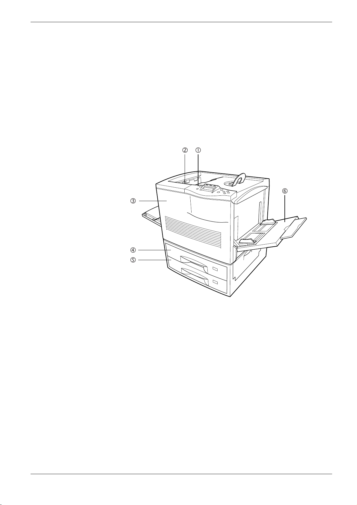
1.2.1 Front
1.2 Parts and Functions
Figure 1-1
1 Operator Panel
Used to specify printer functions and display the printer operating status.
2 Paper-full Sensor
This sensor detects the tray full condition. When the Face-down tray is full, the printer
stops operating and urges you to clear the Face-down tray.
3Front Cover
When open, this cover gives you access to the internal component for replacing toner
containers. The cover must also be open to clear paper jam.
4 Top Paper Cassette (FS-8000C/FS-8000CN)/Duplex Drawer (FS-8000CD)
The cassette holds up to 500 sheets of A5 to A3 sizes. For the FS-8000CD, the top drawer
includes the duplexer for two-sided printing.
5 Bottom Paper Cassette
The cassette holds up to 500 sheets of A5 to A3 sizes as a second paper source (for the
FS-8000C and FS-8000CN).
1-5
Page 21
1.2 Parts and Functions
6 MP (Multi-Purpose) Tray
The MP tray holds up to 150 sheets of standard and non-standard sizes. Transparencies,
envelopes, etc. must be fed using this tray.
Caution
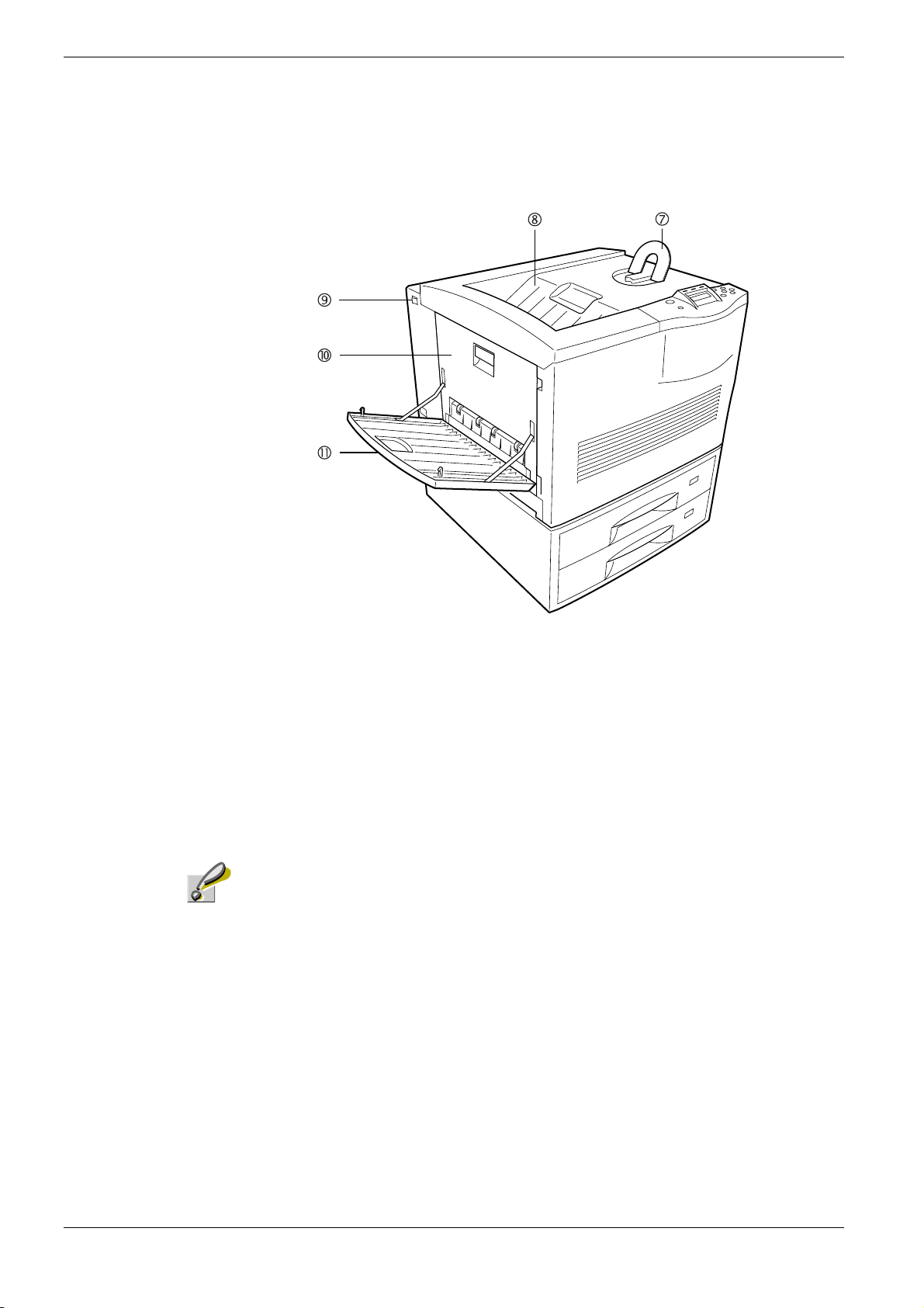
Figure 1-2
7 Paper Stopper
This stopper, when flipped up, prevents the printed sheet of large size from falling.
8 Face-down Tray
This tray receives printouts face down.
9 Power Switch
This switch turns printer power on and off.
The power cord must not be unplugged from power at least 30 minutes since the printer
is switched off.
10 Side Cover
This cover is open by pulling the handle to clear paper jams.
11 Face-up Tray
This tray receives printouts face up.
1-6
Page 22
1.2.2 Internal
1.2 Parts and Functions
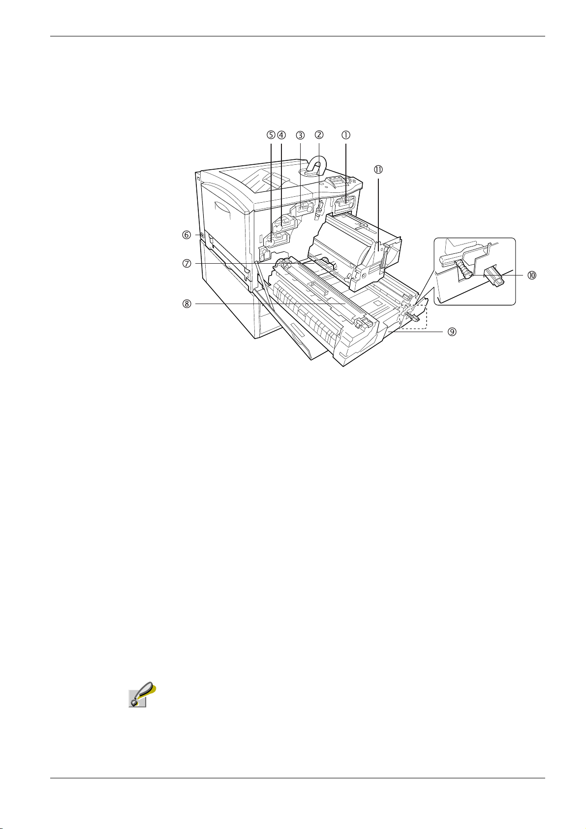
Figure 1-3
1 Black Toner Container
This container holds black (K) toner. You must replace the container when the toner run
out.
2 Main Charger Unit
This is an electrical component used to transfer the toner onto the drum unit. The main
charger unit must be cleaned when you replace the toner container.
3 Yellow Toner Container
This container holds yellow (Y) toner. You must replace the container when the toner run
out.
4 Magenta Toner Container
This container holds magenta (M) toner. You must replace the container when the toner
run out.
5 Cyan Toner Container
This container holds cyan (C) toner. You must replace the container when the toner run
out.
6Power Cord Connector
This connector accepts the power cord supplied with the printer.
Caution
The power cord must not be unplugged from power at least 30 minutes since the printer is
switched off.
7 Waste Toner Bottle
This plastic bottle collects waste toner for later disposal. The bottle has a cap which is
used to seal the bottle opening when being disposed of.
1-7
Page 23
1.2 Parts and Functions
1.2.3 Rear
8Fuser Unit
The fuser unit fixes the toner permanently on the paper. The fuser becomes very hot
during printing.
9 Paper Feed Unit
The paper feed unit transports paper from the paper source for developing and fixing
images.
10 Separation Charger Cleaning Knob
This cleaning knob (green) is used to clean the separation charger. The separation
charger unit must be replaced after every 100,000 pages of printing and requires
professional servicing. Contact your Kyocera Mita dealer.
11 Primary Transfer Unit
This unit is used to create the image developed by toner and to transfer it onto the
surface of the paper.
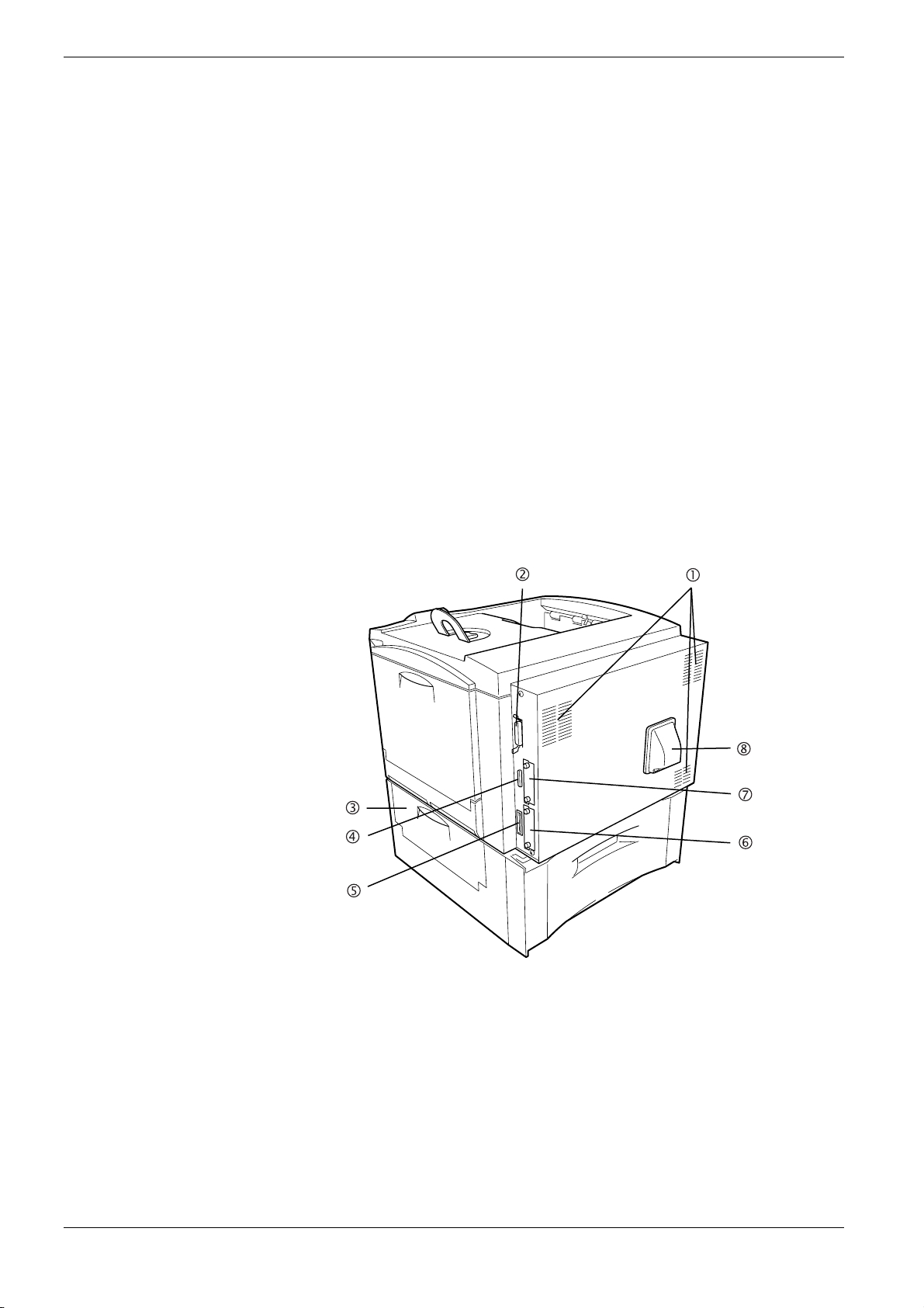
Figure 1-4
1Vents
Air is purged through these vents to cool down the inside.
2 Parallel Interface Connector
This connector is for a standard Centronics parallel interface cable from the computer.
Connect this connector to the computer’s parallel port.
3 Paper Feeder Side Cover
This cover is opened to clear paper jams in the paper feeder section.
1-8
Page 24

1.2 Parts and Functions
4 Serial Interface Connector
This connector is for D-sub 25-pin RS-232C cable from the computer. Connect this
connector to the computer’s serial printer port with a serial cable.
5 Memory Card Slot
This slot receives a memory card. A memory card can hold fonts, macros, forms, etc., that
can be downloaded in the printer’s memory. For details, see Appendix A Options, section
A.3.1 Memory Card on page A-7.
6 Network Interface Card Slot (OPT1)
This slot holds an optional network interface card for network printing. (An optional Hard
disk can’t be used in this slot.) For details see Appendix A Options, section A.3.10 IB-20/
IB-21E Network Interface Cards on page A-13.
7 Hard Disk or Network Interface Card Slot (OPT2/HDD)
This slot holds an optional hard disk for storing print jobs or network interface card for
network printing. A Kyocera Mita manufactured hard disk must be used. For details, see
Appendix A Options, section A.3.8 HD-3 Hard Disk on page A-12.
8 Ozone Filter Duct
The ozone filter behind the duct is provided to prevent the ozone generated in the printer
from escaping out the air.
Caution
Do not block the cooling air in and out vents and the ozone filter duct against walls or with
other objects. If the flow of cooling air is blocked, heat will be built up in the printer, and
there will be a risk of fire.
1-9
Page 25
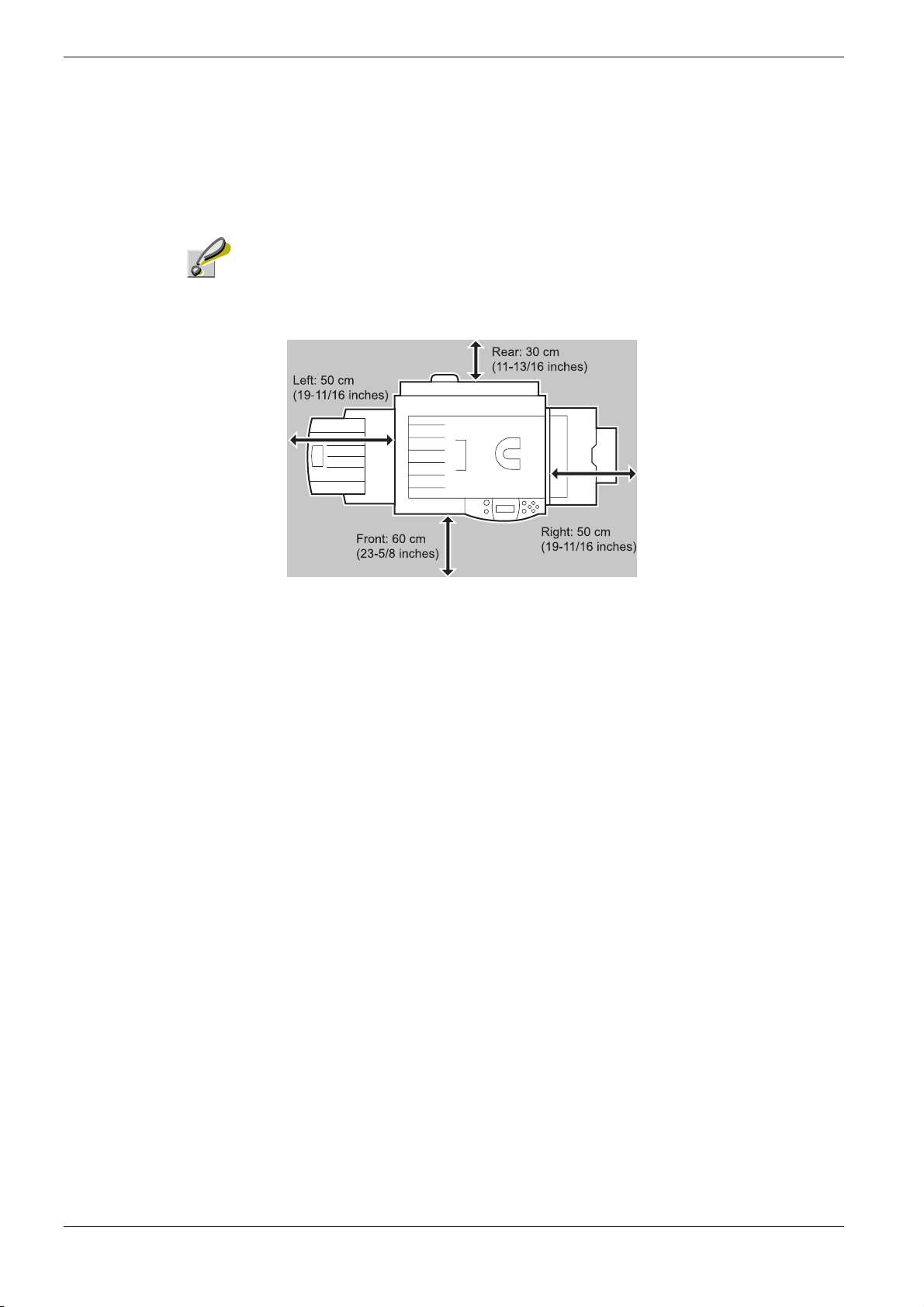
1.3 Clearance
1.3 Clearance
Caution
Allow the following clearance on all sides of the printer.
Prolonged use without sufficient clearance may cause heat to build up within
the printer, resulting in fire.
Left: 50 cm
(19-11/16 inches)
Figure 1-5
1-10
Page 26

Chapter 2 Handling Paper
The printer can use a variety of media in various sizes. However, any media you will choose to
use with the printer must be in accordance with the guidelines and specifications in this
chapter. Use of paper not satisfying these guidelines and specifications may cause problems
such as frequent paper jams, poor quality printing, and possible damage to the printer
mechanism.
Even meeting the instructions provided in this chapter, special media such as transparencies,
labels, envelopes, non-standard-size paper must be fed directly from the printer’s MP (multipurpose) tray and delivered in the face-up tray in ‘straight path’ manner. For details on use of
MP tray, see Chapter 3 Using the Operator Panel, section 3.10.1 MP Tray Mode on page 3-79.
Page 27

2.1 General
2.1 General
The Ecosys Color FS-8000C Series printers are designed for high-grade bond (copy) paper,
like those widely used for ordinary xerographic copiers. The printers will also support other
types of paper as long as they meet the standards explained in this chapter.
Selecting the right paper is very important. Use of unsuitable paper can cause paper jams,
misfeed, curling, poor print quality, and even worse, printer damage. This chapter shows
you how to use your printer in a way that will ensure efficient, error-free printing and
minimal printer damage. This practice will increase your office productivity.
Kyocera Mita will not be liable for any problems that may occur if you use paper that
does not meet these standards.
Note
2.1.1 Available paper types
The FS-8000C Series printers can use almost any type of printer paper. These printers
accept paper used for xerographic copiers as well.
Paper comes in three generic grades: economy, standard, and premium. The grades are
determined by how easily the paper can pass through the printer. This depends on the
smoothness, size, moisture content, and cutting of the paper. The higher the grade, the less
risk of problems (such as paper jams), and higher the print quality.
The differences in paper characteristics of different paper makers also affect the printer
performance. High-performance printers can produce high-quality results only when the
right types of paper are selected. Low-priced paper is not always economical, especially if it
ends up causing frequent printing problems.
Paper of the different grades is available in basis weights (explained later). The
recommended basis weights of paper for the printers are 16, 20, and 24 pounds. When
expressed in grams per square meter, the recommended basis weights range from 60 to 90 g/
2
m
.
2.1.2 Paper specifications
Ta bl e 2- 1 summarizes the basic paper specifications. Details are given on the subsequent
pages.
Item Values
Weight (basis weight)
Thickness 0.086 to 0.110 mm (3.4 to 4.3 mils)
Dimensions See Table 2-3.
Dimensional accuracy
Squareness of corners
Moisture content 4 to 6 %
Cassette: 64 to 90 g/m
MP tray: 64 to 220 g/m
0.7 mm (±0.0276 inches)
±
0.2 °
±
90
2
(17 to 24 lb/ream)
2
(17 to 58 lb/ream)
†
Table 2-1
2-2
Page 28
Item Values
Direction of grain Long grain
Pulp content 80 % or more
Table 2-1 (Continued)
† Paper of 135 to 220 g/m2 thick should be A4 or Letter size and fed laterally.
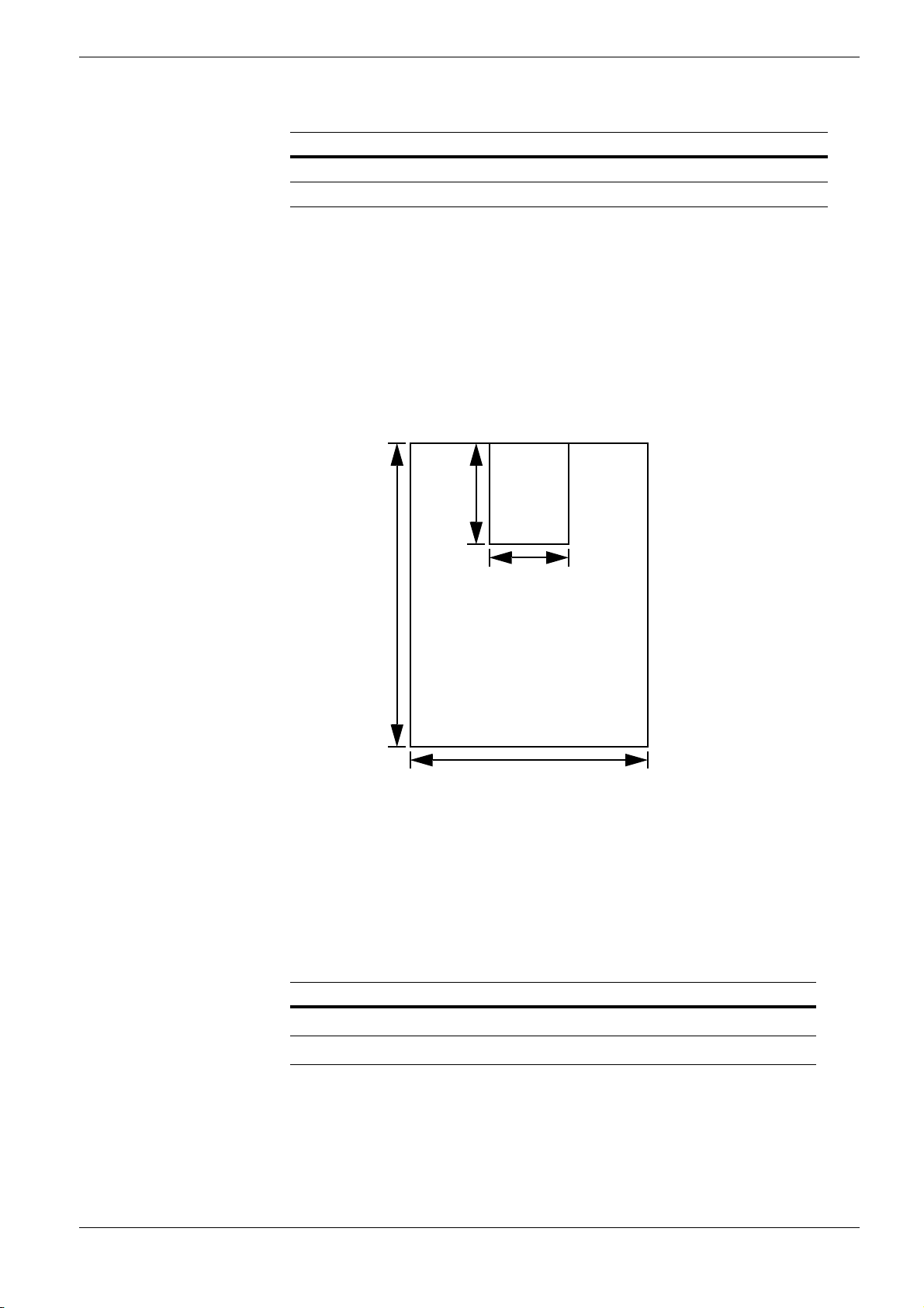
2.1.3 Minimum and Maximum Paper Sizes
The minimum and maximum paper sizes are as follows. For non standard paper such as cutsheet, the MP (multi-purpose) tray must be used.
148 mm
2.1 General
Minimum
Paper
Size
5-13/16 inches
Figure 2-1
2.1.4 Recommended Paper
The following products are recommended for use with the printer for optimum performance.
Size Product Weight
Letter, Legal Hammermill LASER PRINT
A4, A3 NEUSIEDLER COLOR COPY
458 mm
18 inches
80 mm
3-1/8 inches
Maximum
Paper Size
310 mm
12-3/16 inches
90 g/m2 (24 lb)
2
90 g/m
Table 2-2
2-3
Page 29

2.2 Selecting the Right Paper
2.2 Selecting the Right Paper
To get clean, crisp printouts from laser printers all the time, select high-quality printer paper
that meets the printer’s requirements. Laser printers use laser beams, electrostatic discharge,
toner, and heat, all of which affect the paper. Furthermore, paper slide, bends, and twists as
it passes through laser printers during printing. Therefore, printer paper must be able to
withstand such great stress.
This section describes the major considerations for selecting the right printing paper.
2.2.1 Guidelines
Paper conditions
Do not use paper with folded edges, curls, warps, smudges, tears, or embossing. Also do
not use paper containing lint, clay, or paper debris. Using such paper may cause illegible
printing, misfeeds, paper jams, etc., and shorten the product life of the printer. Never use
paper with surface coating or other surface treatment. The paper surface should be as
smooth and even as possible.
Paper composition
Do not use paper with surface-coating or containing plastic or carbon. The heat of fusing
causes such paper to emit toxic fumes.
Bond paper should have at least an 80 % pulp content. The percentage of cotton and other
fibers should not exceed 20 %.
Paper sizes
Table 2-3 lists the standard paper sizes and dimensions. Note that certain paper sizes are
available only for MP tray feeding (as remarked) and face-up tray delivering. For details on
using MP tray, see Chapter 3 Using the Operator Panel, section 3.10.1 MP Tray Mode on
page 3-77.
The dimensional tolerances for these paper sizes are
length and width of paper. The corner angles must be 90
Paper Size Dimensions Remarks
Ledger
Legal
Letter
11
×
8-1/2
8-1/2
17 inches
14 inches
×
11 inches
×
0.7 mm (±0.0276 inches) for both
±
0.2 °.
±
ISO A3
ISO A4
ISO A5
JIS B4
Table 2-3
297
210
148
257
2-4
420 mm
×
297 mm
×
210 mm
×
364 mm
×
Page 30

2.2 Selecting the Right Paper
Paper Size Dimensions Remarks
JIS B5
Monarch
Business
ISO DL
ISO C5
ISO C4
ISO B5
ISO A6
Executive
Commercial 9
Commercial 6-3/4
JIS B6
Japanese postcard
Japanese double-postcard
Custom
182 × 257 mm
3-7/8
7-1/2 inches
×
4-1/8
9-1/2 inches
×
220 mm
×
110
162
229 mm
×
229
324 mm
×
250 mm
×
176
105
148 mm
×
7-1/4
10-1/2 inches
×
8-7/8 inches
×
3-7/8
3-5/8
6-1/2 inches
×
128
182 mm
×
148 mm
×
100
148
200 mm
×
80
148 mm to 310 × 458 mm
×
MP tray only
MP tray only
MP tray only
MP tray only
MP tray only
MP tray only
MP tray only
MP tray only
MP tray only
MP tray only
MP tray only
MP tray only
MP tray only
MP tray only
2.2.2 Paper properties
Smoothness
Paper should have a smooth, uncoated surface. Paper with a rough or sandy surface can cause
gaps in printouts. However, paper with surfaces that are too smooth may cause multiple-sheet
feeding and fogging problems (fogging is a gray background effect).
Basis weights
Basis weight is the weight in pounds of 500 sheets (called a ream) of paper cut to the basic
size, which is 17
to basis weights depend on paper classifications. In the metric system, the basis weight is
expressed in grams per square meter (g/m
Paper that is too heavy or too light may cause misfeeds, jams, and premature wear of printer
parts. Uneven weight of paper can cause multiple-sheet feeding, print defects, poor toner
fusing, blurring, and other print quality problems. The recommended basis weights for this
printer are between 64 and 90 g/m
When you use paper with basis weights of 135 to 220 g/m
quality printouts.
Table 2-3 (Continued)
22 inches. The number of sheets in a ream and the basic paper size relating
×
2
).
2
(17 to 24 lb per ream).
2
, use the face-up tray for high-
Thickness (Caliper)
Thick paper is called high-caliper paper and thin paper is called low-caliper paper. Paper used
by the printer should be neither too thick nor too thin. If you encounter paper jam, multiple-
2-5
Page 31

2.2 Selecting the Right Paper
sheet feed, or too light printing problems, the paper may be too thin. If you encounter paper
jam or too heavy printing problems, the paper may be too thick. The recommended
thickness of a sheet for this printer is between 0.086 and 0.110 mm (from 3.4 to 4.3 mils).
Moisture content
Moisture content is the percentage of the weight of water in paper. Moisture affects the
appearance, feeding, curling, electrostatic properties, toner fusing of the paper.
The moisture content of paper varies with the relative humidity in the room. If the room is
too humid, paper will absorb more moisture. The edges will swell and the paper will
become wavy. If the room is too dry and the paper loses moisture, the edges shrink and
tighten, and the print contrast may be degraded.
Wavy or tight edges can cause paper misfeeds and misalignments. The recommended
moisture content is between 4 and 6 %.
To maintain the correct moisture content level, store the paper in an environment that allows
moisture control. These are tips for moisture control:
• Store paper in a cool, dry place.
• Leave packages of paper wrapped as long as possible. Rewrap unused paper.
• Return paper to its paper carton, whenever possible. Place the cartons on a pallet or
other furniture so that they are not in direct contact with the floor.
• Before using paper stored for an extended period of time, condition it in the printer’s
environment for at least 48 hours.
• Do not expose paper to heat, direct sunlight, or damp.
Grain
Technically, grain is the direction of paper in the paper machine. Grain is parallel with the
direction of movement in the paper machine. Grain long means that the grain runs along the
length of the sheet, and grain short means that the grain runs along the width of the sheet.
Because grain short causes paper feed problems, always select grain long for the printers.
2-6
Page 32

2.2.3 Other properties of paper
Porosity
The density of paper structure, which indicates the compactness of the fiber bonding. It is also
the characteristic that allows air to pass through paper (i.e., air permeability).
Stiffness
The ability of paper to resist deformation under stress. In the printer, limp paper can buckle
and too stiff paper can bind. Both conditions result in paper jams.
Curl
Most paper naturally tends to curl one way. To produce flat printouts, load the paper sheets so
that the upward pressure from the printer can correct their curling. When loading paper, it is
also important to distinguish between the front side and backside of the paper. Be sure to
follow the paper loading instructions printed on the paper carton.
2.2 Selecting the Right Paper
Electrostatic discharge
During the printing process, paper is given an electrostatic charge to attract the toner.
Therefore, the paper must discharge the static electricity so that the printouts do not stick to
each other in the output tray.
Whiteness
The contrast of printed images depends on the whiteness of the paper. Whiter paper produces
sharper and clearer images.
Quality control
Uneven paper sizes, corners that are not square, jagged paper edges, irregularly cut sheets, torn
edges and corners, etc. can cause various printer troubles. Before purchasing paper, find out
whether the paper store always takes measures to prevent such problems in its products.
Packaging
Paper sheets should be shipped in strong cartons to protect them from damage during
transportation. Before purchasing paper, make sure the store ships its products in proper
packages.
2-7
Page 33

2.3 Special Paper
2.3 Special Paper
Besides plain paper, this printer can use the following types of special paper:
• Transparencies
• Pre-printed
• Labels
•Bond
• Recycled
• Vellum
• Rough
• Letterhead
•Color
• Pre-punched
• Envelope
• Card stock
•Coated
• Second side
†
• Customs
† Paper printed using this printer only. You cannot use paper already copied or printed by another
printer.
You can assign one of these special paper type to a paper cassette or MP (multi-purpose)
tray by using the printer’s operator panel keys. Then, the printer can automatically select the
paper cassette or malti-purpose tray to feed the special paper from and internally adjust the
electrical parameters for optimum printing performance according to the special paper type.
For details, see Chapter 3 Using the Operator Panel, section 3.10.4 Setting the Cassette
Paper Type on page 3-82.
Note that some types of special paper do not allow feeding from the paper feeder cassette or
duplex (two-sided) printing.
2.3.1 Selecting the Special Paper
Since special paper differs significantly in paper composition and quality, special paper is
more likely to cause problems than white bond paper during printing. When using special
paper, be sure that they are manufactured for photocopiers and/or laser printers.
Before purchasing any special paper, make a test print using the printer and check whether
the results are satisfactory.
Kyocera Mita shall not be liable for any danger to a person or machine that is caused
by using special paper (e.g., fumes emitted from the special paper).
Note
To avoid problems, stack transparencies, labels, or envelopes on the tray or cassette face up.
Major considerations for each type of special paper are given below.
2-8
Page 34

2.3 Special Paper
Transparency
Transparencies for overhead projectors must withstand the heat of fusing during the printing
process. The recommended transparency product is as follows:
3M CG3700 (Letter, A4)
Transparencies must be placed on the MP (multi-purpose) tray with the long edge towards the
printer. To avoid problems, stack transparencies face up on the face-up tray.
When unloading transparencies (e.g., for clearing jams), hold them carefully by the edges to
avoid leaving fingerprints on them.
Adhesive-backed labels
Label paper must be fed manually.
For printing on labels, use extreme care so that the adhesive may not come in direct contact
with any part of the printer. Adhesives that stick to the drum or rollers will cause printer
damage.
Labels consist of three parts. Printing is done onto the top sheet (also called the face sheet).
The adhesive contains chemicals. The carrier sheet (also called the backing paper or liner)
bears the top sheet. This composition of labels can cause more problems than other print forms
during printing.
Top sheet (white bond paper)
Adhesive
Carrier sheet
Figure 2-2
When using label paper, do not leave gaps between the arranged labels (i.e., top sheets). Labels
arranged with gaps in-between can easily be peeled off during printing, causing serious jam
problems.
When the label paper has extra margin around the label’s outside edges that correspond to the
margins of the printable area, do not remove the extra top sheet from the carrier sheet until
printing is finished.
Not allowedAllowed
Top sheet
Figure 2-3
Carrier sheet
2-9
Page 35

2.3 Special Paper
When selecting labels, make sure to use only those meeting the following requirements:
Item Value
Top shee t wei ght
Total weight
Top sheet thickness 0.086 to 0.107 mm (3.9 to 4.2 mils)
Total thickness 0.115 to 0.145 mm (4.5 to 5.7 mils)
Moisture content 4 to 6 % (composite)
Table 2-4
44 to 74 g/m
104 to 151 g/m
2
(12 to 20 lb)
2
(28 to 40 lb)
Envelopes
Envelopes must be fed manually.
Since the composition of an envelope is more complex than that of ordinary paper, it is not
always possible to ensure consistent printing quality over the entire envelope surface.
Normally, envelopes have a diagonal grain direction. See section Grain on page 2-6. This
direction can easily cause wrinkles and creases when envelopes pass through the printer.
Before purchasing envelopes, make a test print to check whether the printer accepts the
envelope.
Other handling cautions follow:
• Do not use envelopes that have an encapsulated liquid adhesive.
• Avoid a long printing session for envelopes only. Extended envelope printing can cause
premature printer wear.
• To avoid jams caused by curled envelopes, stack the printed envelopes no higher than
10 on the output tray.
Colored paper
Colored paper should have the same specifications as the white bond paper listed. In
addition, the pigments in the paper must be able to withstand the heat of fusing during the
printing process (up to 200
C or 392 °F).
°
Pre-printed paper
Pre-printed paper should basically be bond paper. The inks on the paper must be able to
withstand the heat of fusing during the printing process and must not be adversely affected
by silicon oil. Do not use paper with any kind of coating, such as calendar stock.
Recycled paper
Select recycled paper that has the same specifications as white bond paper. See Table 2-1 on
page 2-2. Recycled paper, however, does not have to be as white as white bond paper.
Note
Before purchasing recycled paper, make a test using the printer and check whether
the print quality is satisfactory.
2-10
Page 36

Chapter 3 Using the Operator Panel
This chapter provides the information you need to configure the Ecosys Color printer. In
general you need to use the operator panel only to make default settings. You can make most
changes to the printer settings using the printer driver trough the application software. For
details, see Chapter 4 Printer Drivers and Utilities.
Changes to printer settings made using a software application override changes made
using the operator panel.
Note
You can also rely on other printer utilities such as Kyocera Mita PrintMonitor if you need to
change settings that are not available on the printer driver. It will allow you remotely access to
printer settings. Printer utilities are supplied in the software CD-ROM supplied with the
printer.
The chapter describes the operator panel in detail, including its menus and the procedures for
changing various printer settings.
Page 37

3.1 Understanding the Operator Panel
3.1 Understanding the Operator Panel
The operator panel on the top of the printer has a 2-line by 16-character liquid crystal display
(LCD), eight keys, and three indicators (LED).
Ready
PAR A4 PLAIN
INTERFACE
SIZE
TYPE
Figure 3-1
Messages that appear on the display and functions of indicators and keys are explained in the
sections that follow.
3.1.1 Message Display
The message display on the operator panel shows:
• Status information, the eight messages listed below which are displayed during normal
• Error codes, when the printer requires the operator’s attention; as explained in Chapter 5
Status Information
operation.
Troubleshooting.
Message Meaning
Self test The printer is performing self-diagnostics after power-up.
Please wait The printer is warming up and is not ready.
When the printer is switched on for the first time, the message
display shows Adding toner which will take several
minutes.
Table 3-1
3-2
Page 38

3.1 Understanding the Operator Panel
Message Meaning
Please wait
(Calibrating)
Ready The printer is ready to print.
Processing The printer is receiving data to print. This is also shown when
Sleeping The printer is in sleep mode. The printer wakes from sleep
Cancelling data Jobs inside the printer are being canceled. To cancel a job, see
Waiting The printer is waiting for the rest of print job before complet-
FormFeed TimeOut The printer is printing the last page after a waiting period.
The color calibration function is being performed automatically as you powered on the printer.
You can also execute this function manually on the operator
panel. For details, see Section 3.11.4 Color Calibration on
page 3-100.
the printer is reading a memory card or hard disk.
mode whenever a key on the operator panel is pressed, the
cover is opened or closed, or a print job is received. The printer
then warms up and goes on-line. For details on sleep mode, see
Section Sleep Timer Timeout Time on page 3-107.
Section 3.1.3 Keys on page 3-6 .
ing the last page. Pressing the GO key allows you to obtain the
last page immediately. See below.
Table 3-1 (Continued)
Error codes
See Chapter 5 Troubleshooting.
3.1.2 Indicators in Message Display
Figure 3-2
Interface Indicator (INTERFACE)
The interface indicator shows the interface that is currently in use:
PAR Parallel interface is in use.
SER Serial (RS-232C) interface is in use.
OP1 (2) Network interface is in use.
--- No interface is in use.
Each interface has a timeout time of 30 seconds during which the other interface should wait to
receive a print job. Even a print job has been complete on the interface, you should wait for
this period until the other interface begins printing the job.
3-3
Page 39

3.1 Understanding the Operator Panel
Paper Size Indicator (SIZE)
This indicator indicates:
• While the printer is in standby, the paper size of the cassette. The default paper cassette is
• While the printer is printing, the paper size used to format the document to print by the
The abbreviations used to indicate the paper sizes and their dimensions are as follows:
A3 ISO A3 (29.7 × 42 cm)
A4 ISO A4 (21 × 29.7 cm)
A5 ISO A5 (14.8 × 21 cm)
A6
B4 JIS B4 (25.7 × 36.4 cm)
B5 JIS B5 (18.2 × 25.6 cm)
B6
LT Letter (8-1/2 × 11 inches)
LD Ledger (11 × 17 inches)
LG Legal (8-1/2 × 14 inches)
MO
BU
DL
C4
C5
b5
EX
#6
#9
HA
OH
CU
determined by the operator panel keys. For details, see Section 3.10 Paper Handling on
page 3-79.
application software.
ISO A6 (10.5 × 14.8 cm)
JIS B6 (12.8 × 18.2 cm)
Monarch (3-7/8 × 7-1/2 inches)
Business (4-1/8 inches)
ISO DL (11 × 22 cm)
ISO C4 (22.9 × 32.4 cm)
ISO C5 (16.2 × 22.9 cm)
ISO B5 (17.6 × 25 cm)
Executive (7-1/4 × 10-1/2 inches)
Commercial 6-3/4 (3-5/8 × 6-1/2 inches)
Commercial 9 (3-7/8 × 8-7/8 inches)
Japanese Postcard (10 × 14.8 cm)
Return Postcard (20 × 14.8 cm)
Custom Size (8 × 14.8 cm to 31 × 45.8 cm)
†
†
†
†
†
†
†
†
†
†
†
†
†
†
† Only with MP tray feeding
Paper Type Indicator (TYPE)
This indicator shows the paper type defined for the current paper casette. The paper type can
be manually defined using the operator panel. For more information, see Section 3.10 Paper
Handling on page 3-79.
The following abbreviations are used:
(none) Auto
PLAIN Plain paper
TRNSPRNCY
Transparency
†
PREPRINTE Pre-printed paper
LABELS
Labels
†
BOND Bond paper
3-4
Page 40

3.1 Understanding the Operator Panel
RECYCLED Recycled paper
VELLUM
Vellum
†
ROUGH Rough paper
LETTERHEA Letterhead
COLOR Colored paper
PREPUNCH Pre-punched paper
ENVELOPE
CARDSTOCK
Envelope
Card stock
†
†
COATED Coated paper
2ND SIDE Second side of paper
CUSTOM1 (to 8) Custom 1 (to 8)
† Only with MP tray feeding
READY, DATA, and ATTENTION Indicators
The following indicators light during normal operation and whenever the printer needs
operator’s attention. Depending on the status of lighting, each indicator has the following
meaning:
READY
DATA
ATTENTION
Table 3-2
Indicator Description
Flashing. Indicates an error that you can recover by yourself,
such as the loose front cover. For details, see Chapter 5 Trou-
bleshooting, section 5.3.1 Error Messages on page 5-7.
On. Indicates that the printer is ready and on-line. The printer
prints the data it receives.
Off. Indicates that the printer is off-line. Data can be received
but will not be printed until the printer is on-line by pressing
the GO key. Also, indicates when printing is automatically
stopped due to the occurrence of an error. For details see
Chapter 5 Troubleshooting, section 5.3.1 Error Messages on
page 5-7.
Flashing. Indicates that a data is being received from the
computer.
On. Indicates either that data received is being processed
before printing starts, or that data received is being written to a
memory card or a hard disk.
Flashing. Indicates that the printer requires maintenance or is
warming up.
On. Indicates the occurrence of a problem or an error. For
details, see Chapter 5 Troubleshooting, section 5.3.1 Error
Messages on page 5-7.
3-5
Page 41

3.1 Understanding the Operator Panel
3.1.3 Keys
The operator panel keys are used to configure the printer operation. Note that certain keys
have the secondary function.
The printer has a parallel, serial, and an optional network interface. Configuration to the
printer settings made with these keys affect only one of these interfaces that is currently
Note
active (indicated by the INTERFACE indicator on the message display). See Interface
Indicator (INTERFACE) on page 3-3.
GO Key
The GO key switches the printer between on-line and off-line. Use this key to:
• Toggle the printer’s on-line and off-line states. You can temporarily stop the print job by switching the
• Print and feed out one page when the printer displays Waiting.
printer off-line.
CANCEL Key
This key is used to:
• Cancel a printing job
• Stop the alarm sound
• Reset numeric values or cancels a setting procedure while using menu system
To cancel a printing job:
While the printer displays Processing, press the CANCEL key.
1
Print Cancel? appears on the message display followed by the interface which the
job to cancel is on. The interface is indicated by one of the following message:
Parallel
Serial
Option 1
Option 2
If you wish to abort the cancellation procedure, press the CANCEL key again.
Press the ENTER key. Cancelling data appears on the message display and
2
printing stops after the current page is printed.
3-6
Page 42

3.1 Understanding the Operator Panel
MENU Key
The MENU key lets you enter the menu system to change the setup and printing environment
of the printer.
Pressing this key during a menu selection will terminate the selection and return the printer to
the normal operation.
Arrow Keys
The four arrow keys are used in the menu system to access a desired item or enter numeric
values.
The arrow key with the question mark (?) may be pressed when the paper jam message has
appeared on the message display. Then a help message will appear to facilitate jam clearing in
the location.
ENTER Key
The ENTER key finalizes settings of numeric values and other selections.
3-7
Page 43

3.2 Using the Menu Selection System
3.2 Using the Menu Selection System
This section explains how to use the menu selection system. The MENU key on the operator
panel allows you to enter the menu when the printer is in ready state.
The printer operates according to the most recent printer settings sent from the
application software, or from the printer driver, which take priority over the settings
Note
3.2.1 Menu System Road Map
made using the menu selection system.
The overview of the printer’s menu system is diagrammed below and on the following pages.
For convenience, the printer can print out the simplified version of menu map. To print a menu
map, see Section 3.3.1 Printing a Menu Map on page 3-14.
The shaded items mean that these are available only when the corresponding optional device is
installed in the printer. For example, e-MPS and its submenus will not appear unless a hard
disk is installed in the printer.
Ready
PAR A4 PLAN
MENU Key
Print
Menu Map
Print
Status Page
e-MPS >
>Quick Copy
>Private/Stored
>Print VMB Data
>List of VMB
>List of
Code JOB
>e-MPS >
Configuration
>>Quick Copy
>>Temp.Code JOB
Size
>>Perm.Code JOB
Size
>>VMB Size
Continued on the next page
3-8
Page 44

3.2 Using the Menu Selection System
Continued
Interface >
Parallel
Interface >
Serial
Interface >
Option 1
Interface >
Option 2
>Parallel I/F
Auto
>Baud rate
9600
>Data Bits
8
>Stop Bits
1
>Parity
None
>Protocol
DTR (pos.)&XON
>Barcode Mode
Off
>NetWare
Off
>NetWare >
On
>TCP/IP
Off
>TCP/IP >
On
>Ether Talk
Off
>OPT. StatusPage
Off
>>NetWare Frame
Auto
>>DHCP
OFF
>>IP Address
>>Subnet Mask
>>Gateway
Emulation >
PCL 5c
Emulation >
KC-GL
Emulation >
KPDL
Emulation >
KPDL (AUTO)
Continued on the next page
>Code Set
ISO-6 ASCII
>KC-GL Pen >
Adjust Pen(1)
>KC-GL Page Set
[SPSZ]
>Print KPDL Errs
Off
>Alt. Emulation
PCL 5c
>Print KPDL Errs
Off
>>Pen(1) Width
01 dot(s)
>Pen(1) Color
Black
3-9
Page 45

3.2 Using the Menu Selection System
Continued
Font >
Page Set >
Print Quality >
Opt. ROM >
>Font Select >
Internal
>Font Select >
Option
>List of
Internal Fonts
>List of
Option Fonts
>Copies
001
>Orientation
Portrait
>Page Protect
Auto
>LF Action
LF only
>CR Action
CR only
>KIR Mode
On
>EcoPrint Mode
Off
>Tone
Normal
>Gloss Mode
Low
>Read Data
>List of
Partitions
>> I000
>>Courier
Regular
>>Letter Gothic
Regular
>>Size
012.00 point(s)
>>Pitch
10.00 cpi
Hard Disk >
Continued on the next page
3-10
>Read Data
>Write Data
>Delete Data
>List of
Partition
Page 46

Continued
RAM Disk Mode
Off
RAM Disk Mode >
On
Memory Card >
Paper Handling >
>RAM Disk Size
>Read Data
>Write Data
>Delete Data
>List of
Partitions
>Read Fonts
>Read Data
>Write Data
>Delete Data
>Format
>List of
Partitions
>MP Tray Mode
First
>MP Tray Size
A4
>MP Tray Type
Plain
>Cassette 1 Type
Plain
>Cassette 2 Type
Plain
>Feed Select
Cassette 1
>Duplex Mode
None
>Stack Select
Face-down tray
>Opt.StackerMode
None
>Override A4/LT
Off
>Type Adjust >
Custom 1
>Reset Type
Adjust
3.2 Using the Menu Selection System
>>Paper weight
Normal
>>Fuser Mode
Low
>Duplex Path
Disable
Continued on the next page
3-11
Page 47

3.2 Using the Menu Selection System
Continued
Clolor Mode >
Color
Life Counters >
>RGB Simulation
None
>Ink Simulation
None
>Color
Calibration
>Total Print
>Oil Kit
>New Toner[C]
Installed
>New Toner[M]
Installed
>New Toner[Y]
Installed
>New Toner[K]
Installed
Continued on the next page
3-12
Page 48

3.2 Using the Menu Selection System
Continued
Others >
>MSG Language
English
>Form Feed
Time Out 030sec.
>Sleep timer >
030 min.
>Print HEX-DUMP
>Printer Reset
>Resource Prot.
Off
>Buzzer
On
>Auto Continue >
Mode On
>Auto Continue
Mode Off
>Service >
>>Sleep Mode
On
>>Auto Continue
Timer 000sec.
>>Print
Status Page
>>Print
Test Page 1
>>Print
Test Page 2
>>Drum
>>Developer
>>Maintenance
[A]
>>Maintenance
[B]
>>Maintenance
[C]
>>Maintenance
[D]
3-13
Page 49

3.3 Menu Map and Status Pages
3.3 Menu Map and Status Pages
This section explains the procedure for printing the printer’s internal information using the
menu selection system. The menu map is usefull as a reference to guide yourself through the
menu selection system.
The status page is a list of parameters and settings for most basic printer configurations. You
may be required to produce a status page when requesting service to the printer.
3.3.1 Printing a Menu Map
The printer prints a full list of menu selection system — Menu Map. Note that menus shown in
the list may vary depending on which optional units installed in the printer.
Press the MENU key.
1
Press the U or V key repeatedly until Print Menu Map appears.
2
Print
Menu Map
Press the ENTER key. A question mark (?) appears.
3
Print
Menu Map ?
If you wish to abort the printing of the menu map, press the CANCEL key.
Press the ENTER key. The message Processing appears and the printer prints a
4
Menu Map.
An example Menu Map is shown on the next page.
3-14
Page 50

MENU MAP
3.3 Menu Map and Status Pages
FS-8000C Page Printer
Figure 3-3
3-15
Page 51

3.3 Menu Map and Status Pages
3.3.2 Printing a Status Page
You can check the printer’s current status, including available memory space and option
settings by printing a status page.
Press the MENU key.
1
Press the U or V key repeatedly until Print Status Page appears.
2
Print
Status Page
Press the ENTER key. A question mark (?) appears.
3
Print
Status Page ?
If you wish to abort printing of the status page, press the CANCEL key.
Press the ENTER key again. The message Processing appears and the printer
4
prints a status page.
For a sample status page and its full description, see Understanding the Status Page on
page 3-17.
3-16
Page 52

3.3 Menu Map and Status Pages
Understanding the Status Page
The numbers in the following diagram refer the items explained below the diagram. The items
and values on the status page may vary depending on the printer’s firmware version.
FS-8000C Page Printer
STATUS PAGE
Hardware Information
2
Page Information
4
Network Status
Firmware Version: Released:
Memory
Installed Options
Emulation
1
3
5
7
6
Error Log
8
Consumable Status
9
Interfaces
Figure 3-4
10
3-17
Page 53

3.3 Menu Map and Status Pages
1 Software Version
This item shows the version and release date of the printer firmware.
2 Hardware Information
This item shows various printer settings for hardware-related items:
• MP tray paper size and type
• Paper cassette size and type
•Draft mode
• Buzzer control
• Host buffer size
• Sleep time timeout time
• Formfeed timeout time
3Memory
This item shows:
• Standard memory in the printer (64 MB)
• Option memory slot status (Slots 1 and 2) in megabytes
• Total memory in the printer
• Current status of the RAM disk
4 Page Information
This item shows the page related items:
• Tone mode, Normal or Fine
• Number of copies, from 1 to 999
• Total page count
5 Installed Options
This item shows the options installed in the printer:
• Hard disk
• Option ROM
• Memory card
6 Network Status
This item shows the IP address, subnet mask address, and default gateway address for the
network interface card in the printer.
7Emulation
This item shows all available emulations of the printer. The PCL 5c emulation is set as
default when the printer is shipped from the factory. The emulations are:
•PCL 5c
•KPDL3
•KC-GL
3-18
Page 54

3.3 Menu Map and Status Pages
8 Error Log
This item shows the last three instances of the following four types of errors, listing them
in the order of occurrence:
• KPDL (PostScript) errors
• Memory overflow
• Print overrun
• File-not-found
The most recent error is displayed on the topmost line of Error Log. Error information is
cleared when the printer is powered off.
The error log information is intended for service purpose.
9 Consumable Status
This item shows the approximate level of remaining toner. When the value is 100, the
toner container is full. The closer to 0, the smaller the amount of remaining toner.
10 Interface Information
This information shows the emulation and the default font for all interfaces installed in
the printer.
3-19
Page 55

3.4 e-MPS
3.4 e-MPS
Note
e-MPS is an abbreviation for ‘enhanced-Multiple Printing System’ which implements the
following functions that are available from the printer driver:
• Job Retention
• Job Storage
In either job mode, when printing a document, the print data is transferred from the computer
to the printer then stored on the printer’s hard disk. Since copies of the document are printed
using the stored data, printing is performed faster with less computer spooling time and less
network traffic.
To use the e-MPS system, an optional hard disk must be installed in the printer. (FS8000CN is equipped with a hard disk as a standard feature.) For details, see Appendix A
Options.
Job Retention
Job Retention has four modes as summarized below. These modes are selected when you
choose on the printer driver through the application software:
Mode Quick Copy Proof-and-Hold Private Print Stored Job
Primary function To later print addi-
tional copies
Start storing by Printer driver Printer driver Printer driver Printer driver
Retrieved by Operator panel Operator panel Operator panel Operator panel
Default number of
copies printed at
retrieval
Maximum number
of jobs stored
PIN security No No Yes Yes
Hard disk
††
required
Table 3-3
† Jobs in excess will cause the earlier ones to be deleted.
†† RAM disk does not work for e-MPS.
Same as storing One less Same as storing One
32, expandable to 5032, expandable to 50Private jobs are
†
Yes Yes Yes Yes
To proof the first
copy before printing multiple copies
To hold the document in printer to
prevent unauthorized access
deleted automatically once it is
retrieved.
To eletronically
documents
store
such as fax cover
pages
No limit
Job Storage
Job storage stores print jobs either temporarily or permanently, or in virtual mailboxes, as you
click an appropriate radio button on the printer driver when printing from a computer. If you
select Temporary or Permanent job storage, you can choose to have a unique number and
barcode automatically assigned to each job as it is stored in the printer. This barcode appears
on the printed document. The barcode reader can be used to reprint the document by reading
3-20
Page 56

3.4 e-MPS
the barcode from the original document or from a List of Code Jobs. For details on this list, see
Printing a List of Code Jobs on page 3-29.
Job storage requires a hard disk installed in the printer. However, printing barcoded job IDs on
documents is possible using the RAM disk feature of the printer. On how to use the RAM disk,
see Section 3.9.1 Setting up the RAM Disk on page 3-69.
Virtual Mailbox
Virtual mailbox is part of Job Storage, which stores print jobs on the hard disk without
printing. It enables you to retrieve jobs later from the operator panel, the KM-NET Printer
Disk Manager utility (in the CD-ROM), or the barcode reader.
Each mailbox may be used by an individual who desires to share the printer in this mode. By
default, each mailbox is numbered from ‘Tray 001,’ ‘Tray 002,’ ... etc. To ‘post’ a job in one of
these mailboxes, you assign a numbered or named mailbox on the printer driver when printing.
To retrieve the stored job for printing, see Retrieving Jobs from Virtual Mailbox (VMB) on
page 3-30.
The virtual mailbox can be used in PCL 5c emulation only.
Note
3.4.1 Using Quick Copy
This mode enables you to print the requested number of copies of a job, simultaneously storing
the job on the hard disk. When additional copies are required, you can reprint the required
number of copies from the printer operator panel. To print a job as a quick copy job, see
Chapter 4 Printer Drivers and Utilities.
The default number of print jobs that can be stored on the hard disk is 32. This value can be
increased to up to 50 from the e-MPS Configuration menu. For details, see Section 3.4.7
Changing e-MPS Configuration on page 3-32. When the number of jobs reaches the limit, the
oldest job will be overwritten by the new one.
When the printer is turned off, all stored jobs will be deleted.
3-21
Page 57

3.4 e-MPS
Printing Additional Copies using Quick Copy
To print additional copies of a job stored in the printer:
Press the MENU key.
1
Press the U or V key repeatedly until
2
e-MPS >
Press the Z key.
3
Press the U or V key repeatedly until >Quick Copy appears followed by the user
4
name (Harold, in this example). The user name is assigned at printing using the
printer driver.
>Quick Copy
Harold
Press the ENTER key. A blinking question mark (?) appears before the user name.
5
>Quick Copy
?Harold
e-MPS >
appears.
Press the U or V key to display the desired user name, Arlen, in this example.
6
>Quick Copy
?Arlen
Press the ENTER key. The job name entered in the printer driver (Report, in this
7
example) appear with a blinking question mark (?) before the letters.
>Arlen
?Report
Press the U or V key to scroll to the desired job title.
8
3-22
Page 58

3.4 e-MPS
Press the ENTER key. The number of copies to be printed can be set. To increase the
9
copy count, press the U key; to decrease the copy count, press the V key.
>Report
Copies 001
Press the ENTER key to finalize the copy count. The printer prints the specified
10
number of copies for the job.
Deleting a Quick Copy Job
All quick copy jobs are automatically deleted when the printer is turned off. If you desire to
explicitly delete a stored quick copy job, proceed as follows:
Follow steps 1 through 8 in the above section to let the title of the job to be deleted
1
displayed.
When the title of the job to be deleted is displayed, e.g. Report, below, press the
2
ENTER key. The cursor below the copy count starts to blink.
>Report
Copies 001
Press the V key repeatedly until Delete appears below the title.
3
>Report
Delete
Press the ENTER key. The stored quick copy job is deleted.
4
3.4.2 Using Proof-and-Hold
When you print multiple copies, this mode first prints one copy so that you can proof it before
continuing to print the remaining copies. Since you can proof the printouts before printing the
remaining copies, wastage of paper can be reduced.
The printer prints one copy and, at the same time, saves the print job on the hard disk. You can
also change the number of copies when resuming printing from the operator panel.
When the printer is turned off, all stored jobs will be deleted.
Printing Remaining Copies of a Proof and Hold Job
Printing a Proof-and-Hold job on the operator panel is similar to printing a quick copy job. To
print remaining copies of a job held in the printer:
Press the MENU key.
1
3-23
Page 59

3.4 e-MPS
Press the U or V key repeatedly until
2
e-MPS >
Press the Z key.
3
Press the U or V key repeatedly until >Quick Copy appears followed by the user
4
name (Harold, in this example). The user name is assigned at printing using the
printer driver.
>Quick Copy
Harold
Press the ENTER key. A blinking question mark (?) appears before the user name.
5
>Quick Copy
?Harold
e-MPS >
appears.
Press the U or V key to display the desired user name, Arlen, in this example.
6
>Quick Copy
?Arlen
Press the ENTER key. The job name entered in the printer driver (Report, in this
7
example) appear with a blinking question mark (?) before the letters.
>Arlen
?Report
Press the U or V key to scroll to the desired job title.
8
Press the ENTER key. The number of copies to be printed can be set. To increase the
9
copy count, press the U key; to decrease the copy count, press the V key.
>Report
Copies 001
3-24
Page 60

Press the ENTER key to finalize the copy count. The printer prints the specified
10
number of copies for the job.
3.4.3 Printing a Private Job
In private printing, you can specify that a job is not printed until you release the job from the
operator panel. At sending the job from the application software, you should specify a 4-digit
access code in the printer driver. The job is released for printing by entering the access code on
the operator panel. Thus, this function ensures confidentiality of the print job.
When the printer is turned off, all the print jobs will be deleted.
Releasing a Private Job
Press the MENU key.
1
3.4 e-MPS
Press the U or V key repeatedly until e-MPS > appears.
2
e-MPS >
Press the Z key.
3
Press the U or V key repeatedly until >Private/Stored appears. The name
4
entered in the printer driver (Harold, in this example) also appears.
>Private/Stored
Harold
Press the ENTER key. A blinking question mark (?) appears before the user name.
5
>Private/Stored
?Harold
Press the U or V key to display the desired user name (Arlen, in this example).
6
>Private/Stored
?Arlen
3-25
Page 61

3.4 e-MPS
Press the ENTER key. The user name and the job name (
7
entered in the printer driver appear with a blinking question mark (?).
>Arlen
?Agenda
Press the U or V key to display the desired job title.
8
Press the ENTER key. The ID input line appears. Enter the four-digit access code
9
entered in the printer driver and press the ENTER key. To enter the ID, press the Y or
Z key to move the cursor to the number to be changed and then enter the correct
number by pressing the U or V key.
>Agenda
ID 0000
You can set the number of copies to be printed. To increase the copy count, press the U
10
key; to decrease the copy count, press the V key.
Agenda
, in this example)
>Agenda
Copies 001
Press the ENTER key to finalize the copy count. The printer prints the specified
11
number of copies for the job.
Deleting a Private Job
Follow steps 1 through 8 in the above section.
1
When the title of the job to be printed is displayed (Agenda, in this example), press the
2
ENTER key. Enter the four-digit access code entered in the printer driver and press the
ENTER key.
>Agenda
Copies 001
Press the V key repeatedly until Delete appears for the number of copies.
3
>Agenda
Delete
Press the ENTER key. The private job is deleted from the hard disk.
4
3-26
Page 62

3.4.4 Storing a Print Job
You can download a job to the hard disk without printing it. This allows you to store print jobs
that are frequently needed such as fax cover pages, check lists, and order forms, for printing at
any later time using the operator panel.
When the printer is turned off, all the print jobs will be deleted.
Releasing a Stored Job
To print a stored job through the operator panel:
1
2
3.4 e-MPS
Press the MENU key.
Press the U or V key repeatedly until e-MPS > appears.
e-MPS >
Press the Z key.
3
Press the U or V key repeatedly until >Private/Stored appears. The name
4
entered for User Name in the printer driver (Harold, in this example) also appears.
>Private/Stored
Harold
Press the ENTER key. A blinking question mark (?) before a user name appears.
5
>Private/Stored
?Harold
Press the U or V key to display the desired user name (Arlen, in this example).
6
>Private/Stored
?Arlen
Press the ENTER key. The user name and the job name entered in the printer driver
7
(Agenda, in this example) appear with a blinking question mark (?) before the letter.
>Arlen
?Agenda
3-27
Page 63

3.4 e-MPS
Press the U or V key to display the desired job title.
8
Press the ENTER key. If you entered an access code for the printer driver, the ID input
9
line appears. Enter the four-digit access code entered in the printer driver and press the
ENTER key. To enter the ID, press the Y or Z key to move the cursor to the number to
be changed and then enter the correct number by pressing the U or V key.
You can specify the number of copies to print. To increase the copy count, press the U
10
key; to decrease the V key.
>Agenda
Copies 001
Press the ENTER key to finalize the copy count. The printer prints the specified
11
number of copies for the job.
>Agenda
?Copies 001
Deleting a Stored Job
Follow steps 1 through 8 in the above section.
1
When the title of the job to be printed is displayed (Agenda, in this example), press the
2
ENTER key. If you entered an access code for the printer driver, enter the four-digit
access code and press the ENTER key.
>Agenda
Copies 001
Press the V key repeatedly until Delete appears for the number of copies.
3
>Agenda
Delete
Press the ENTER key. The stored job is deleted from the hard disk.
4
3-28
Page 64

3.4.5 Printing a List of Code Jobs
If you select Permanent Job Storage on the printer driver, you can have a List of Code Job
printed using the operator panel. The List of Code Job may be used to read the barcode
assigned for the stored job you want to reprint by using a barcode scanner. See Appendix A
Options.
A sample Code Job List is shown in Figure 3-5 on page 3-30.
Press the MENU key.
1
Press the U or V key repeatedly until e-MPS > appears.
2
e-MPS >
Press the Z key.
3
3.4 e-MPS
Press the U or V key repeatedly until >List of Code JOB appears.
4
>List of
Code JOB
Press the ENTER key. A question mark (?) appears.
5
>List of
Code JOB ?
Press the ENTER key again. The printer prints a Code Job list as shown in Figure 3-5
6
below.
3-29
Page 65

3.4 e-MPS
FS-8000C Page Printer
PERMANENT CODE JOB LIST
Figure 3-5
3.4.6 Retrieving Jobs from Virtual Mailbox (VMB)
To retrieve the jobs posted in the virtual mailbox, proceed as follows.
Press the MENU key.
1
Press the U or V key repeatedly until e-MPS > appears.
2
e-MPS >
Press the Z key.
3
Press the U or V key repeatedly until >Print
4
mailbox number will also appear.
Data appears. The virtual
VMB
>Print VMB Data
Tray001
If you have named the virtual mailbox with an alias on the printer driver, the alias
(Richard, in this example) will follow the number:
>Print VMB Data
Tray001
:
:Richard
3-30
Page 66

Press the ENTER key. A blinking question mark (?) appears.
5
>Print VMB Data
Tray001
Press the ENTER key. The document in the mailbox is printed and automatically
6
deleted from the mailbox.
Printing a List of VMB
A Virtual Mailbox list includes the jobs currently stored in the mailboxes.
Press the MENU key.
1
Press the U or V key repeatedly until e-MPS > appears.
2
?
3.4 e-MPS
e-MPS >
Press the Z key.
3
Press the U or V key repeatedly until >List of VMB appears.
4
>List of VMB
Press the ENTER key. A question mark (?) appears.
5
>List of VMB ?
Press the ENTER key again. The printer prints a list of jobs currently posted in the
6
virtual mailboxes as shown in Figure 3-6 below.
3-31
Page 67

3.4 e-MPS
Figure 3-6
3.4.7 Changing e-MPS Configuration
FS-8000C Page Printer
VIRTUAL MAIL BOX LIST
Note
You can change the following parameters for e-MPS operation:
• Maximum number of Quick Copy/Proof-and-Hold jobs
• Maximum space assigned to temporary code jobs
• Maximum space assigned to permanent code jobs
• Maximum space assigned to virtual mailboxes
The total amount of storage areas specified must not exceed the total size of the hard
disk. Otherwise, you may only be able to accommodate print jobs of a smaller amount of
print jobs than specified.
Changing the Maximum Number of Quick Copy/Proof-and-Hold Jobs
This changes maximum number of Quick Copy/Proof-and-Hold jobs from 0 to 50. The default
is 32.
Press the MENU key.
1
Press the U or V key repeatedly until e-MPS > appears.
2
e-MPS >
Press the Z key.
3
3-32
Page 68

3.4 e-MPS
Press the U or V key repeatedly until
4
>e-MPS >
Configuration
Press the Z key.
5
Press the U or V key repeatedly until >>Quick Copy appears.
6
>>Quick Copy
32
Press the ENTER key. A blinking cursor (_) appears.
7
>>Quick Copy
32
>e-MPS Configuration >
appears.
Press the U or V key to increase or decrease the value at the blinking cursor. The value
8
can be set between 0 and 50. Use the Z and Y keys to move the cursor right and left.
When the desired maximum number of jobs is set, press the ENTER key.
9
Press the MENU key. The display returns to Ready.
10
Maximum Space Assigned to Temporary Code Jobs
This changes the hard disk space that holds temporary code jobs. You can change the
maximum space from 0 to 9999 (megabytes). The actual maximum size depends on the size of
free hard disk space, however. The default size is 1/6 of the total hard disk space, rounded off
in unit of 50 MB. For example, if the total hard disk space is 3.2 GB, the default size is 500
MB.
Press the MENU key.
1
Press the U or V key repeatedly until e-MPS > appears.
2
e-MPS >
3-33
Page 69

3.4 e-MPS
Press the Z key.
3
Press the U or V key repeatedly until
4
>e-MPS >
Configuration
Press the Z key.
5
Press the U or V key repeatedly until >>Temp. Code JOB Size appears.
6
>>Temp. Code JOB
Size 050MB
To change the maximum disk space, press the ENTER key. A blinking cursor (_)
7
appears.
>>Temp. Code JOB
Size 05
0MB
>e-MPS Configuration >
appears.
Press the U or V key to increase or decrease, respectively, the value at the blinking
8
cursor. Use the Z and Y keys to move the cursor right and left.
When the desired size is displayed, press the ENTER key.
9
Press the MENU key. The display returns to Ready.
10
3-34
Page 70

3.4 e-MPS
Maximum Space Assigned to Permanent Code Jobs
This changes the hard disk space that holds permanent code jobs. You can change the
maximum space from 0 to 9999 (megabytes). The actual maximum size depends on the size of
free hard disk space, however. The default size is 1/6 of the total hard disk space, rounded off
in unit of 50 MB. For example, if the total hard disk space is 3.2 GB, the default size is 500
MB.
Press the MENU key.
1
Press the U or V key and select e-MPS >.
2
e-MPS >
Press the Z key.
3
Press the U or V key and select >e-MPS Configuration >.
4
>e-MPS >
Configuration
Press the Z key.
5
Press the U or V key and select >>Perm. Code JOB Size.
6
>>Perm. Code JOB
Size 050MB
Press the ENTER key, the message display shows a blinking cursor (_).
7
>>Perm. Code JOB
Size 05
0MB
Press the U or V key to increase or decrease, respectively, the value at the blinking
8
cursor. Use the Zand Y keys to move the cursor right and left.
3-35
Page 71

3.4 e-MPS
When the desired size is displayed, press the ENTER key.
9
Press the MENU key and the message display returns to
10
Maximum Space Assigned to Virtual Mailboxes (VMB)
This changes the hard disk space for virtual mailboxes. You can change the maximum space
from 0 to 9999 (megabytes). The actual maximum size depends on the size of free hard disk
space, however. The default size is 1/6 of the total hard disk space, rounded off in unit of 50
MB. For example, if the total hard disk space is 3.2 GB, the default size is 500 MB.
Press the MENU key
1
Press the U or V key and select e-MPS >.
2
e-MPS >
Press the Z key.
3
Ready
.
Press the U or V key and select >e-MPS Configuration >.
4
>e-MPS >
Configuration
Press the Z key.
5
Press the U or V key and select >>VMB Size.
6
>>VMB Size
050MB
To change the maximum size, press the ENTER key. The message display shows a
7
blinking cursor (_).
>>VMB Size
05
0MB
3-36
Page 72

Press the U or V key to increase or decrease, respectively, the value at the blinking
8
cursor. Use the Z and Y keys to move the cursor right and left.
When the desired size is displayed, press the ENTER key.
9
Press the MENU key to exit the menu selection.
10
3.4 e-MPS
3-37
Page 73

3.5 Changing the Interface Parameters
3.5 Changing the Interface Parameters
Communication parameters for the printer interfaces can be adjusted as explained below.
The FS-8000CN has an network interface card installed at the factory. For information on how
to remotely change parameters for the network interface card, refer to the documentation
supplied with the printer.
3.5.1 Changing Parallel Interface Mode
The parallel interface supports a bi-directional/high-speed mode according to IEEE standards.
You can select from the following:
• Auto (default)
• Nibble/high speed
• Normal
• High speed
In order for the change to take place, you must turn printer power once off then on.
Press the MENU key.
1
Press the U or V key repeatedly until Interface > appears.
2
If the interface is other than parallel, press the ENTER key. A blinking question mark
3
(?) appears.
Interface
? Serial
Press the U or V key repeatedly until Parallel appears.
4
Interface
? Parallel
Press the ENTER key again. The question mark disappears.
5
To change the parallel interface mode, press the Z key. The current communication
6
mode appears.
3-38
Page 74

3.5 Changing the Interface Parameters
To change the communication mode, press the ENTER key. A blinking question mark
7
(?) appears.
>Parallel I/F
? Auto
Press the U or V key to scroll through the following communication modes:
8
Auto
Nibble (high)
Normal
High Speed
When the desired communication mode is displayed, press the ENTER key.
9
Press the MENU key to exit the menu selection.
10
3.5.2 Changing Serial Interface Parameters
You can confirm or change the serial interface parameters including baud rate, data bits, stop
bits, parity, and protocol. These parameters must match those of the computer’s serial
interface.
Press the MENU key.
1
Press the U or V key repeatedly until Interface > appears.
2
If the interface is other than serial, press the ENTER key. A blinking question mark (?)
3
appears.
Interface
? Parallel
Press the U or V key repeatedly until Serial appears.
4
Interface
? Serial
Press the ENTER key again.
5
3-39
Page 75

3.5 Changing the Interface Parameters
Press the Z key. One of the following serial parameters is indicated (
6
example).
Pressing the U or V key toggles through the serial parameters as follows. To change
the serial parameter, press the ENTER key. Use the U or V key to change the value or
selection.
Range
>Baud rate
1200, 2400, 4800, 9600 (Default), 19200, 38400, 57600,
115200
Baud rate
9600
>Data bits
7 or 8 (Default)
8
>Stop bits
1 (Default) or 2
1
for
>Parity
None (Default), Odd, Even, or Ignore
None
>Protocol
DTR (pos.) & Xon (Default), DTR (positive), DTR (negative), Xon/Xoff, ETX/ACK
DTR(pos.)&XON
>Barcode Mode
Off (Default) or On †
Off
† Barcode mode is used when the option barcode reader is connected to the printer to support
reading document IDs (barcodes). Note that Barcode Mode appears in the menu only when
a hard disk option is installed.
For example, to change baud rate from 9600 to 115200, display the baud rate menu following
the above procedure. When the display shows baud rate, 9600 (bps), press the ENTER key. A
blinking question mark (?) appears.
>Baud Rate
? 9600
3-40
Page 76

3.5 Changing the Interface Parameters
Press the U or V key to scroll through values. When
key. Press the MODE key to exit the menu selection.
Some computers may not be able to handle a baud rate of 115200 bps. If you set the
baud rate to 115200 and encounter communication problems, select a lower baud rate.
Note
3.5.3 Changing Network Interface Parameters
This section applies to the FS-8000C series printers having the network interface card
installed. The FS-8000CN comes equipped with a network interface card as a standard
accessory. For details concerning network issues when using the FS-8000CN, refer to the
supplied manual for the network interface card.
Using the operator panel, you can:
• Activate or deactivate TCP/IP, NetWare, and AppleTalk
• Activate or deactivate DHCP
• Enter IP address, subnet mask address, and default gateway address
• Determine whether to print a network status page when the printer is turned on
To confirm or change network card parameters, proceed as follows:
Press the MENU key.
1
115200
is displayed, press the ENTER
Press the U or V key repeatedly until Interface > appears.
2
If the current interface is other than option, press the ENTER key. A blinking question
3
mark (?) appears.
Interface >
? Parallel
Press the U or V key repeatedly until Option appears.
4
Interface >
? Option 1
Press the ENTER key again.
5
Press the Z key. One of the following menus is indicated. To change settings for the
6
item, press the ENTER key. Use the U or V key to change the value or selection.
3-41
Page 77

3.5 Changing the Interface Parameters
Range
>NetWare >
On
>TCP/IP >
On
>EtherTalk
Set this item to On when you connect to a network
using NetWare. In submenu (>), frame mode can be
selected from Auto, Ethernet, 802.2, and
802.3.
Set this item to On when you connect to a network
using TCP/IP. Submenu (>) has items including
DHCP, IP address, subnet mask address, and gateway address. To resolve IP address for the network
card, see 3.5.4 Resolving IP Address below.
EtherTalk must be activated (On) for networking
with Macintosh computers.
Off
>Opt. StatusPage
When the item is set to On, the printer prints out a network status page when it prints the printer status.
On
Activate the appropriate protocol that is required to connect the printer to the network.
7
To activate a protocol, let the protocol displayed, press the ENTER key, press the U or
V key to change from Off to On, and press the ENTER key.
Press the MENU key. The display returns to Ready. You can print a network status
8
page to confirm that the IP address, subnet mask address, and the gateway address have
been properly set. To print a network status page, see Printing a Network Interface
Card Status Page on page 3-44 which follows.
3-42
Page 78

3.5.4 Resolving IP Address
To connect the printer to the network using TCP/IP protocol, you must set the IP address on
the printer. The IP address must be unique to the printer and should be obtained from your
network administrator.
Activate TCP/IP protocol in the manner described above.
1
>TCP/IP >
On
Enter the submenu by pressing the Z key. Each time you press the U or V key, the
2
selection changes as shown below.
>>DHCP
Off
3.5 Changing the Interface Parameters
>>IP Address
000.000.000.000
>>Subnet Mask
000.000.000.000
>>Gateway
000.000.000.000
When >>IP Address is displayed, press the ENTER key. A bliking cursor (_)
3
appears at the last digit.
>>IP Address
000.000.000.000
Press the U or V key to increase or decrease, respectively, the value at the blinking
4
cursor. Use the Z and Y keys to move the cursor right and left.
When the IP address is entered, press the ENTER key.
5
Press the U or V key to move to Subnet Mask. Perform the same procedure to
6
complete entering the subnet mask address.
3-43
Page 79

3.5 Changing the Interface Parameters
Then, press the U or V key to move to
7
complete entering the subnet mask address.
Press the MENU key. The display returns to Ready. You can print a network status
8
page to confirm that the IP address, subnet mask address, and the gateway address have
been properly set. To print a network status page, see Printing a Network Interface
Card Status Page which follows.
Printing a Network Interface Card Status Page
You can have your printer print out a network status page when the printer prints the status
page. The network status page shows the network addresses, and other information under
various network protocols about the network interface card. The default setting is On (print).
A sample network status page is shown on Figure 3-7 on page 3-46.
Press the MENU key.
1
Press the ENTER key repeatedly until Interface > appears.
2
Gateway
. Perform the same procedure to
Interface >
Parallel
If the interface is other than Option, press the ENTER key. A blinking question mark
3
(?) appears.
Interface
? Parallel
Press the U or V key repeatedly until Option appears. Press the ENTER key.
4
Interface
? Option 1
Press the Z key and then press the U or V key repeatedly until the display shows
5
>Opt. StatusPage.
>Opt. StatusPage
On
3-44
Page 80

3.5 Changing the Interface Parameters
The default setting is On. If it is set to
6
mark (?) appears.
>Opt. StatusPage
? Off
Press the U or V key to select On.
7
>Opt. StatusPage
? On
Press the ENTER key again.
8
Press the MENU key. The display returns to Ready. The printer prints a network status
9
page as an example shown in Figure 3-7 below.
, press the ENTER key. A blinking question
Off
3-45
Page 81

3.5 Changing the Interface Parameters
NETWORK STATUS PAGE
FS-8000C
Page 1 of 2
Figure 3-7
3-46
Page 82

3.6 Making Default Settings
Using the operator panel, you can set the default for the following items. Note default settings
made using the operator panel may be overridden by the printer driver settings and application
software.
3.6.1 Default Emulation
You can change the emulation mode and character code set for the current interface. The
printer is capable of the following emulation modes:
• HP PCL 5c (HP Color LaserJet 8550)
• KC-GL (HPGL 7550A)
• KPDL3 (PostScript 3 Version 3011)
The printer can automatically switch between HP PCL 5c and KPDL3 depending on the print
job that is received from the computer. To do this, select KPDL (AUTO) in the following
procedure.
3.6 Making Default Settings
Press the MENU key.
1
Press the U or V key repeatedly until Emulation > appears on the message display.
2
One of the emulation modes appears, indicating the emulation currently in use.
PCL 5c (default)
KC-GL
KPDL
KPDL (AUTO)
To change the default emulation, press the ENTER key. A blinking question mark (?)
3
appears.
Emulation
?PCL 5c
Press the U or V key repeatedly until the desired emulation mode is displayed.
4
3-47
Page 83

3.6 Making Default Settings
If you have selected PCL 5c as the default emulation, you can change the character
5
code set. (Default is
To change the character code set of the PCL 5c emulation mode, press the Z key. The
>Code set
>Code Set
IBM PC-8
Press the ENTER key. Press the U or V key repeatedly until the desired character
6
code set appears. Press the ENTER key again to finalize setting.
Press the MENU key. The display returns to Ready.
7
3.6.2 KC-GL Pen Width and Color
IBM PC-8
submenu is displayed.
.) Otherwise, press the ENTER key and go to step 6.
The KC-GL emulation mode enables you to set the pen widths in dots, individual pen colors
for pen numbers 1 to 8, and the KC-GL page size.
Press the MENU key.
1
Press the U or V key repeatedly until Emulation appears on the message display.
2
If the current emulation is other than KC-GL, press the ENTER key. A blinking
3
question mark (?) appears.
Press the U or V key repeatedly until KC-GL appears.
4
Press the ENTER key.
5
Emulation >
KC-GL
Press the Z key to move to the >KC-GL Pen Adjust> submenu.
6
3-48
Page 84

3.6 Making Default Settings
To change the pen width and/or pen color, press the ENTER key. A blinking question
7
mark (?) appears.
>KC-GL Pen >
Adjust ? Pen (1)
Press the U or V key repeatedly until the desired pen number of 1 to 8 appears.
8
When the desired pen number is displayed, press the ENTER key.
9
To change the pen width, press the Z key, then press the ENTER key. A blinking
10
cursor appears at the width value.
>>Pen(1) Width
02
Press the U or V key repeatedly until the desired pen width in dots (00 to 99) appears.
When the desired pen width is displayed, press the ENTER key.
To set the pen color, press the U or V key. To change the pen color, press the ENTER
11
key. A blinking question mark (?) appears.
>>Pen(1) Color
? Black
Press the U or V key repeatedly until the desired pen color (Black, Red, Green,
Yellow, Blue, Magenta, Cyan, White) appears. When the desired pen color is
displayed, press the ENTER key.
To set the KC-GL page size, press the Y key twice, then Press the U or V key until
12
>KC-GL Page Set is displayed.
To change the page size, press the ENTER key. A blinking question mark (?) appears.
13
dot(s)
>KC-GL Page Set
? [A2]
Press the U or V key repeatedly until the desired page size (A2, A1, A0, B3, B2, B1,
B0, and SPSZ) appears. The SPSZ command sets the paper edge limits to the
dimensions of a standard paper size. See this command
Manual in the CD-ROM.
Press the MENU key. The display returns to Ready.
14
Press the ENTER key to set the page set you just selected.
3-49
explained in the Programming
Page 85

3.6 Making Default Settings
3.6.3 Alternative Emulation for KPDL Emulation
The auto KPDL (
emulation mode according to the print job received. The emulation mode the printer switches
alternatively can be selected using the operator panel. The default alternative emulation is HP
PCL 5c.
Press the MENU key.
1
Press the U or V key repeatedly until Emulation > appears.
2
Emulation >
PCL 5c
Press the ENTER key. A blinking question mark (?) appears.
3
Emulation
?PCL 5c
Press the U or V key repeatedly until KPDL (AUTO) appears.
4
KPDL (AUTO)
) emulation enables the printer to automatically change the
Emulation
?KPDL (AUTO)
Press the ENTER key.
5
Press the Z key. Press the U or V key until >Alt. Emulation is displayed. The
6
alternative emulation currently selected also appears — PCL 5c or KC-GL.
To change the alternative emulation, press the ENTER key. A blinking question mark
7
(?) appears.
>Alt. Emulation
?PCL 5c
Press the U or V key until the desired alternative emulation appears.
8
Press the ENTER key.
9
3-50
Page 86

3.6 Making Default Settings
Press the MENU key. The message display returns to
10
3.6.4 Printing KPDL Errors
The printer can print error descriptions when printing error occurs during KPDL emulation.
The default is Off — the printer does not print KPDL errors.
Press the MENU key.
1
Press the U or V key repeatedly until Emulation > appears.
2
Press the ENTER key. A blinking question mark (?) appears.
3
Emulation >
PCL 5c
Emulation >
?PCL 5c
.
Ready
Select KPDL or KPDL (AUTO) using the U or V key.
4
Emulation
?KPDL
Press the ENTER key.
5
Press the Z key. Press the U or V key until >Print KPDL Errs (errors) appears.
6
>Print KPDL Errs
Off
Press the ENTER key. A blinking question mark (?) appears.
7
Select On using the U or V key.
8
>Print KPDL Errs
? On
Press the ENTER key.
9
3-51
Page 87

3.6 Making Default Settings
3.6.5 Default Font
Press the MENU key. The display returns to
10
You can select the default font for the current interface. The default font can be one of the
internal fonts or a font that is downloaded to the printer memory or stored on memory card or
hard disk.
In this menu, you can also set the type and pitch for Courier and Letter Gothic; as well as to
print a font list.
Press the MENU key.
1
Press the U or V key repeatedly until Font > appears.
2
Ready
.
Font >
Press the Z key. Press the U or V key until >Font Select > appears.
3
>Font Select >
Internal
To select an internal font, make sure that Internal is displayed and press the Z key.
4
The display changes as shown below. If Internal is not displayed, Press the ENTER
key, then press the U or V key until it appears.
>> I000
To select an optional font, press the ENTER key while >Font Select > is
displayed. Press the U or V key repeatedly until Option appears and then press the
ENTER key. Press the Z key next to display the font selection shown above. You can
perform this operation only when optional fonts are installed in the printer.
The letter before the number indicates the location of the font, as shown below:
I Internal font
S Soft (downloaded) font
M Fonts in optional memory card
H Fonts in RAM disk or optional hard disk
O Fonts in optional ROM (API)
Press the ENTER key. A blinking question mark (?) appears.
5
>>?I000
3-52
Page 88

3.6 Making Default Settings
Press the U or V key repeatedly until the desired font number appears. For font
6
numbers of the internal fonts, see Printing Lists of Fonts on page 3-56.
When the desired font is displayed, press the ENTER key.
7
Press the MENU key. The message display returns to Ready.
8
Selecting Regular or Dark Courier/Letter Gothic
Courier or Letter Gothic font thickness can be selected as Regular or Dark. In the procedure
below, it is assumed that Courier is selected. The procedure is the same for Letter Gothic.
Press the MENU key.
1
Press the U or V key repeatedly until Font > appears.
2
Font >
Press the Z key. Press the U or V key until >Font Select > appears.
3
>Font Select >
Internal
Make sure that Internal is displayed and press the Z key.
4
Press the U or V key repeatedly until >>Courier appears.
5
>>Courier
Regular
Press the ENTER key. A blinking question mark (?) appears.
6
>>Courier
? Regular
Select Regular or Dark using the U or V key.
7
3-53
Page 89

3.6 Making Default Settings
Press the ENTER key.
8
Press the MENU key. The display returns to
9
Changing the Default Font Size
You can change the size of the default font. If you selected a proportional font, the character
size can also be changed.
Press the MENU key.
1
Press the U or V key repeatedly until Font > appears.
2
Font >
Press the Z key. Press the U or V key until >Font Select > appears.
3
>Font Select >
Internal
Ready
.
Make sure that >Font Select > is displayed and press the Z key.
4
Press the U or V key repeatedly until >>Size appears.
5
>>Size
012.00 point(s)
Press the ENTER key. A blinking cursor (_) appears.
6
>>Size
012.00
Press the U or V key to increase or decrease the value at the blinking cursor. The font
7
size can be set between 4 and 999.75 points, in 0.25-point increments. Use the Z or Y
key to move the cursor right and left.
point(s)
3-54
Page 90

When the desired size is displayed, press the ENTER key.
8
3.6 Making Default Settings
Press the MENU key. The display returns to
9
Character Pitch for Courier/Letter Gothic
You can set the character pitch for fixed fonts when the default font is Courier or Letter
Gothic.
Press MENU key.
1
Press the U or V key repeatedly until Font > appears.
2
Font >
Press the Z key. Press the U or V key until >Font Select > appears.
3
>Font Select >
Internal
Ready
.
Make sure that Internal is displayed and press the Z key.
4
Press the U or V key repeatedly until >>Pitch appears.
5
>>Pitch
10.00 cpi
Press the ENTER key. A blinking cursor (_) appears.
6
>>Pitch
10.00
Press the U or V key to increase or decrease the value at the blinking cursor. The
7
character pitch can be set between 0.44 and 99.99 characters per inch, in 0.01 characterper-inch increments. Use the Z or Y key to move the cursor right and left.
cpi
When the desired size is displayed, press the ENTER key.
8
3-55
Page 91

3.6 Making Default Settings
Press the MENU key. The display returns to
9
Printing Lists of Fonts
To help you decide in selecting a font, you can printout lists of the internal fonts or the optional
fonts including downloaded fonts. Samples for font lists are shown in Figure 3-8 on page 3-
57.
Press the MENU key.
1
Press the U or V key repeatedly until Font > appears.
2
Font >
Press the Z key.
3
Ready
.
Press the U or V key repeatedly until >List of Internal Fonts or >List
4
of Option Fonts appears.
>List of
Internal Fonts
Press the ENTER key. A question mark (?) appears.
5
>List of
Internal Fonts?
Press the ENTER key again. Processing appears, then Ready. The printer prints
6
out a list of fonts with a sample and font ID (number) for each of them. Sample lists of
fonts are shown in Figure 3-8 on the next page.
3-56
Page 92

3.6 Making Default Settings
Internal Scalable and Bitmapped Fonts List
Font Name Scalable/Bitmap Password Selection [FSET] Font ID
Internal Scalable and Bitmapped Fonts List
Font Name Scalable/Bitmap Password Selection [FSET] Font ID
PRESCRIBE
PRESCRIBE
Figure 3-8
3-57
Page 93

3.7 Pagination
3.7 Pagination
In Page Set menus, you can set the number of copies, page orientation, and other settings
regarding pagination.
3.7.1 Number of Copies
You can set the number of copies of each page to be printed for the current interface. The
number of copies can be set between 1 and 999.
1
2
Press the MENU key.
Press the U or V key repeatedly until Page Set > appears.
Page Set >
Press the Z key.
3
Press the U or V key repeatedly until >Copies appears.
4
>Copies
001
Press the ENTER key. A blinking cursor (_) appears.
5
>Copies
001
Press the U or V key to increase or decrease, respectively, the value at the blinking
6
cursor. Use the Z and Y keys to move the cursor right and left.
When the desired size is displayed, press the ENTER key.
7
Press the MENU key. The display returns to Ready.
8
3-58
Page 94

3.7.2 Print Orientation
You can select portrait (upright) or landscape (sideways) page orientation.
3.7 Pagination
Portrait Orientation
A
Press the MENU key.
1
Press the U or V key repeatedly until Page Set > appears.
2
Page Set >
Landscape Orientation
A
Press the Z key.
3
Press the U or V key repeatedly until >Orientation appears.
4
>Orientation
Portrait
Press the ENTER key. A blinking question mark (?) appears.
5
>Orientation
? Portrait
Select Portrait or Landscape using the U or V key.
6
Press the ENTER key.
7
3-59
Page 95

3.7 Pagination
8
3.7.3 Page Protect Mode
The Page Protect Menu does not normally appear, however,
set to On if a print overrun error occurs due to insufficient printer memory. When this has
happened, be sure to reset Page Protect to Auto (default) in order to maintain the
optimum use of printer memory.
1
2
3
Press the MENU key. The message display returns to
Press the MENU key.
Press the U or V key repeatedly until Page set > appears.
Page set >
Press the Z key.
Ready
Page Protect
.
will be forcibly
Press the U or V key repeatedly until >Page Protect appears.
4
>Page Protect
On
Press the ENTER key. A blinking question mark (?) appears.
5
>Page Protect
? On
Press the U or V key repeatedly until Auto appears.
6
>Page Protect
? Auto
Press the ENTER key.
7
Press the MENU key. The message display returns to Ready.
8
3-60
Page 96

3.7.4 Linefeed (LF) Action
This procedure instructs the printer what to do when it receives a linefeed code (0AH).
•LF Only
Linefeed is performed (Default).
• CR and LF
A linefeed and carriage return are performed.
• Ignore LF
The linefeed is ignored.
1
2
3.7 Pagination
Press the MENU key.
Press the U or V key repeatedly until Page Set > appears.
Page Set >
Press the Z key.
3
Press the U or V key repeatedly until >LF Action appears.
4
>LF Action
LF only
Press the ENTER key. A blinking question mark (?) appears.
5
>LF Action
? LF only
Press the U or V key repeatedly until the desired linefeed action appears.
6
When the desired action is displayed, press the ENTER key.
7
Press the MENU key. The display returns to Ready.
8
3-61
Page 97

3.7 Pagination
3.7.5 Carriage-Return (CR) Action
This procedure instructs the printer what to do when it receives a carriage-return code (0DH).
• CR Only
A carriage-return is performed (Default).
• CR and LF
A linefeed and carriage return are performed.
• Ignore CR
The carriage-return is ignored.
Press the MENU key.
1
Press the U or V key repeatedly until Page Set > appears.
2
Page Set >
Press the Z key.
3
Press the U or V key repeatedly until >CR Action appears.
4
>CR Action
CR only
Press the ENTER key. A blinking question mark (?) appears.
5
>CR Action
?CR only
Press the U or V key repeatedly until the desired carriage-return action appears.
6
When the desired action is displayed, press the ENTER key.
7
Press the MENU key. The message display returns to Ready.
8
3-62
Page 98

3.8 Setting Print Quality
The printer features the Print Quality menu which lets you select:
• KIR (Kyocera Image Refinement) mode (smoothing function, for monochrome printing
only)
• EcoPrint mode (toner saver, for monochrome printing only)
• Tone mode (Normal and Fine)
• Gloss mode (Low and High)
3.8.1 KIR
KIR is the Kyocera’s smoothing function. It refines appearance of printed characters that have
jagged or uneven edges. Note that KIR is effective for monochrome printing only.
3.8 Setting Print Quality
Note
Q
KIR is On (Default).
Figure 3-9
The above diagram is an approximate presentation of KIR.
By default, KIR is activated. To confirm the KIR status or deactivate KIR, proceed as follows:
Press the MENU key.
1
Press the U or V key repeatedly until Print Quality > appears.
2
Print Quality >
KIR is Off.
Press the Z key.
3
3-63
Page 99

3.8 Setting Print Quality
Press the U or V key repeatedly until
4
>KIR Mode
On
To deactivate KIR, press the ENTER key. A blinking question mark (?) appears.
5
>KIR Mode
? On
Press the U or V key to set KIR Off.
6
Press the ENTER key to finalize the selection.
7
Press the MENU key. The display returns to Ready.
8
>KIR Mode
appears.
3.8.2 EcoPrint
Note
EcoPrint enables the printer to consume less toner for a page to save your printing costs. When
EcoPrint mode setting is On, the printing image becomes lighter, but readable.The EcoPrint
setting has no effect on the print speed.
EcoPrint is Off. EcoPrint is On.
Figure 3-10
The above diagram is an approximate presentation of EcoPrint. The default is Off. To
confirm or activate EcoPrint, proceed as follows:
Press the MENU key.
1
Press the U or V key repeatedly until Print Quality > appears.
2
Print Quality >
3-64
Page 100

Press the Z key.
3
3.8 Setting Print Quality
Press the U or V key repeatedly until
4
>EcoPrint Mode
Off
To activate EcoPrint, press the ENTER key. A blinking question mark (?) appears.
5
>EcoPrint Mode
? Off
Press the U or V key to change from Off to On.
6
Press the ENTER key.
7
Press the MENU key. The display returns to Ready.
8
>EcoPrint Mode
appears.
3-65
 Loading...