

Page 1

HPE FlexNetwork VSR1000
Virtual Services Router
EVI Configuration Guide
Part number: 5998-8309R
Software version: VSR1000_HPE-CMW710-E0321P01-X64
Document version: 5W101-20151202
Page 2

© Copyright 2015 Hewlett Packard Enterprise Development LP
The information contained herein is subject to change without notice. The only warranties for Hewlett Packard
Enterprise products and services are set forth in the express warranty statements acco mpanying such
products and services. Nothing herein should be construe d as constituting an additional warranty. Hewlett
Packard Enterprise shall not be liable for technical or editorial errors or omissions co ntained herein.
Confidential computer software. V alid license from Hewlett Packard Enterprise required for possession, use, or
copying. Consistent with FAR 12.211 and 12.212, Commercial Computer Software, Computer Software
Documentation, and T e chnical Data for Commercial Items are licensed to the U.S. Government under vendor’s
standard commercial license.
Links to third-party websites take you outside the Hewlett Packard Enterprise website. Hewlett Packard
Enterprise has no control over and is not responsible for information outside the Hewlett Packard Enterprise
website.
Acknowledgments
Intel®, Itanium®, Pentium®, Intel Inside®, and the Intel Inside logo are trademarks of Intel Corporation in the
United States and other countries.
Microsoft® and Windows® are trademarks of the Microsoft group of companies.
Adobe® and Acrobat® are trademarks of Adobe Systems In corporated.
Java and Oracle are registered trademarks of Oracle and/or its affiliates.
UNIX® is a registered trademark of The Open Group.
Page 3

Contents
Configuring EVI ······························································································· 1
Overview ···························································································································································· 1
Layer 2 connectivity extension issues ········································································································ 1
Network topologies ····································································································································· 2
Terminology ··············································································································································· 3
Working mechanism ··································································································································· 4
Placement of Layer 3 gateways ················································································································· 7
ARP flood suppression ······························································································································· 7
Selective flood ············································································································································ 8
Multihoming ················································································································································ 8
Path MTU ················································································································································· 11
Licensing requirements ···································································································································· 11
EVI configuration task list ································································································································· 11
Configuring EVI basic features ························································································································ 11
Configuring a site ID ································································································································· 12
Configuring an EVI tunnel ························································································································ 12
Assigning a network ID to the EVI tunnel ································································································· 13
Specifying extended VLANs on the EVI tunnel ························································································ 14
Configuring ENDP ···································································································································· 14
Tuning EVI IS-IS parameters ··························································································································· 15
EVI IS-IS configuration task list ················································································································ 16
Creating an EVI IS-IS process ················································································································· 16
Changing the designated site VLAN ········································································································ 17
Optimizing an EVI IS-IS network ·············································································································· 17
Specifying a routing policy for an EVI IS-IS process ················································································ 21
Enabling adjacency change logging········································································································· 22
Configuring SNMP notifications and context for EVI IS-IS ······································································· 22
Configuring Graceful Restart for an EVI IS-IS process ············································································ 23
Increasing the maximum number of MAC entries in an LSP for an EVI IS-IS process ···························· 23
Configuring VLAN mappings ···························································································································· 24
Enabling EVI ARP flood suppression ··············································································································· 24
Enabling EVI flooding for all destination-unknown frames ··············································································· 25
Enabling selective flood for a MAC address ···································································································· 25
Displaying and maintaining EVI ······················································································································· 26
EVI configuration examples ····························································································································· 27
Single-homed EVI network configuration example ·················································································· 27
Multiple-EVI-networks configuration example ·························································································· 35
Document conventions and icons ································································· 39
Conventions ····················································································································································· 39
Network topology icons ···································································································································· 40
Support and other resources ········································································ 41
Accessing Hewlett Packard Enterprise Support ······························································································ 41
Accessing updates ··········································································································································· 41
Websites ·················································································································································· 42
Customer self repair ································································································································· 42
Remote support ········································································································································ 42
Documentation feedback ························································································································· 42
Index ············································································································· 44
i
Page 4
Configuring EVI
Overview
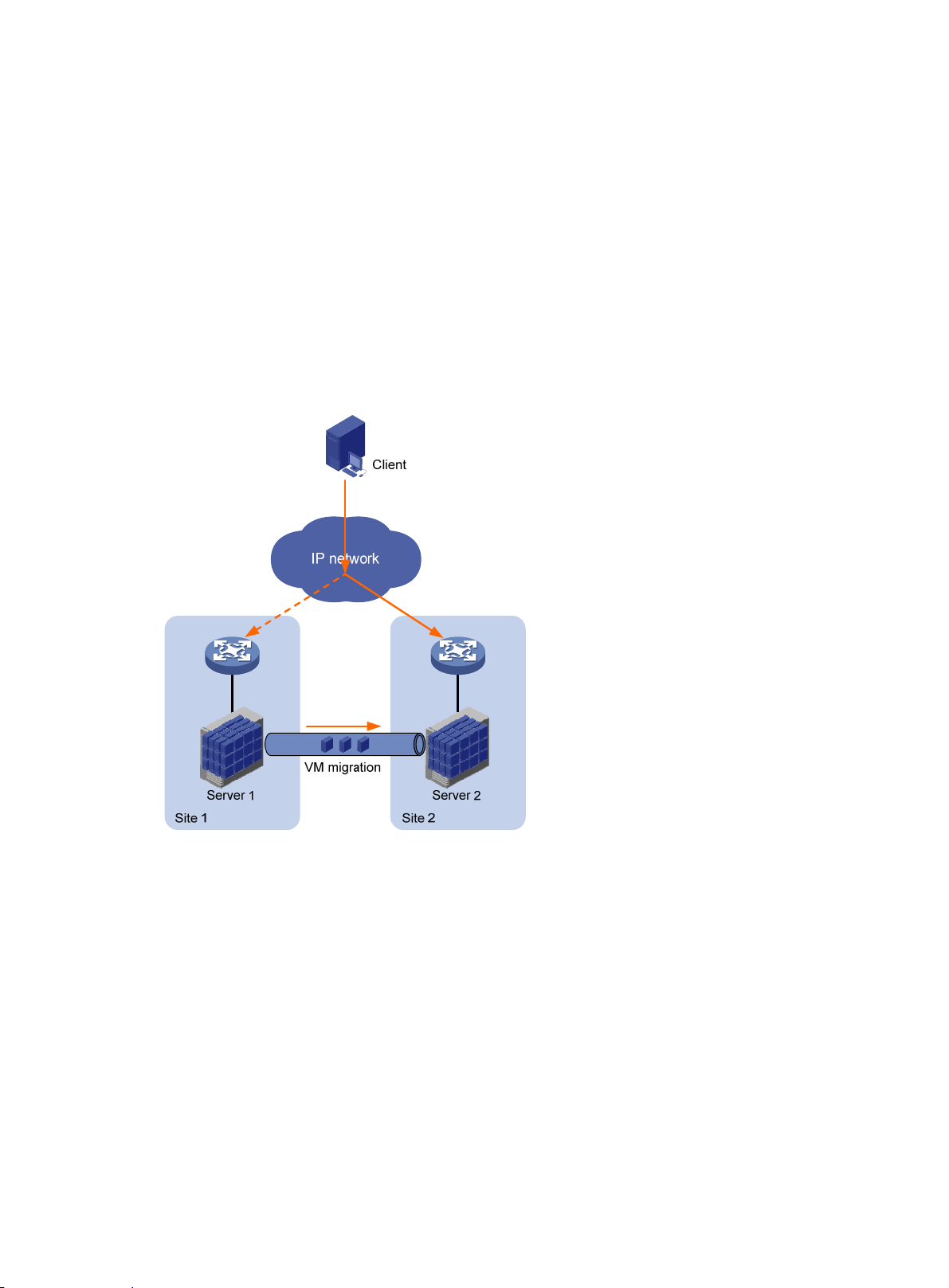
Ethernet Virtual Interconnect (EVI) is a MAC-in-IP technology that provides Layer 2 connectivity
between distant Layer 2 network sites across an IP routed network. It is used for connecting
geographically dispersed sites of a virtualized large-scale data center that requires Layer 2
adjacency (see Figure 1).
EVI enable
and business continuity. For example, virtual machines can move between data center sites without
changing their IP addresses, so their movements are transpare nt to use rs and do not disrupt traffic.
Figure 1 Virtual machine migration
s long-distance virtual machine workload mobility and data mobility, disaster recovery,
Layer 2 connectivity extension issues
EVI resolves the following Layer 2 connectivity extension issues:
• Site independence—EVI keeps protocol failures, such as broadcast sto rms, from propagating
across sites.
• Transport independence—EVI has no special requirements for site location or transport
network type, except that the transport network can forward IP packets.
• High availability—EVI supports redundant edge devices and has a loop-free mechanism to
prevent loops for a multihomed network site.
• Link efficiency—EVI optimizes the inter-site multicast and broadcast transmission mecha nism
and implements load-sharing on redundant links.
• Site and transport transparency—EVI is both site and transport network transparent. It has
no special site or transport network topology requirements.
1
Page 5
• Easy management and maintenance—EVI requires deployment only on edge devices and
does not introduce any topology change or configuration within sites or the transport network.
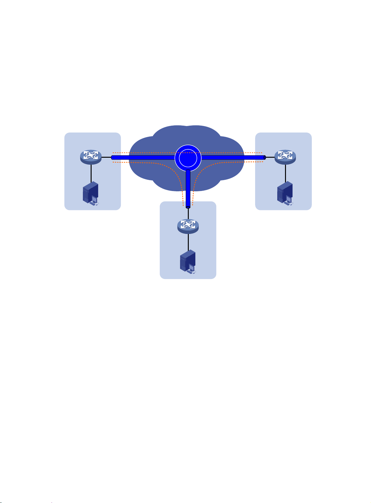
Network topologies
As shown in Figure 2, an EVI network has one or multiple edge devices at each site. These sites are
connected through virtual links and run the EVI IS-IS protocol to advertise their MAC address entries
to each other. EVI maintains MAC routing information on the edge devices without changing the
forwarding or routing information within the sites or the transport network.
Figure 2 EVI network
Site network
VLAN 10
Site 1
Edge
device
EVI link
Transport network
EVI
Site
network
Edge
VLAN 10
Site 2
device
EVI link
EVI link
Site network
Edge
device
Site 3
VLAN 10
EVI supports multiple EVI networks on an edge device for extending different VLANs across the
Layer 3 network. One EVI network can convey multiple VLANs, but one VLAN can map to only one
EVI network. Each EVI network has separate network parameters and independently forwards
traffic.
As shown in Figure 3, EVI
network 1 extends VLAN 100 and VLAN 101 to Site 2, Site 3, and Site 4
for Web access traffic. EVI network 2 extends VLAN 4000 (the management VLAN) to all sites, and
EVI network 3 extends VLANs 50 to 80 between Site 1 and Site 4 for database traffic.
2
Page 6
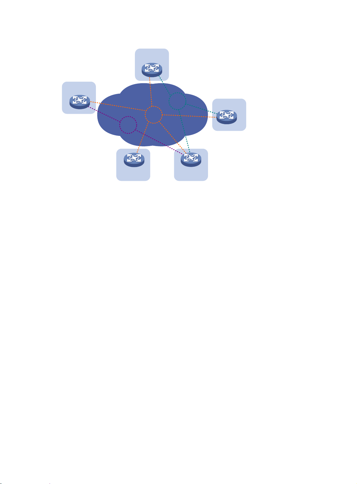
Figure 3 Multiple EVI networks
Site 1
VLAN 4000
EVI 3
VLANs 50-80
Site 2
EVI 2
EVI 1
VLANs 100-101
Site 3
Terminology
Edge device
An edge device performs typical Layer 2 learning and forwarding on the site-facing interfaces
(internal interfaces) and performs tunneling and routing on the transport-facing interfaces.
EVI network ID
An edge device can belong to multiple EVI networks. Each EVI network is uniquely identified by a
network ID.
EVI link
An EVI link is a bidirectional virtual Ethernet channel between a pair of edge devices in an EVI
network. EVI links are conveyed on EVI tunnels. Each EVI link is uniquely identified by a pair of
source and destination EVI tunnel IP addresses.
EVI tunnel
An EVI tunnel is a point-to-many automatic GRE tunnel that conveys EVI links for an EVI network.
One EVI tunnel can provide services only for one EVI network.
EVI neighbor
Site 5
Site 4
ENDP
ENDS
All edge devices in an EVI network are EVI neighbors to one other.
EVI Neighbor Discovery Protocol uses the client/server model to dynamically discover sites and
edge devices, establish and maintain EVI links, and exchange network membership information in
an EVI network.
An EVI neighbor discovery server maintains all neighbor information in an EVI network. An EVI
network can have up to two ENDSs.
3
Page 7

ENDC
An EVI neighbor discovery client works with an ENDS to learn neighbor information and triggers EVI
link setup between neighbors.
EVI IS-IS
EVI IS-IS establishes adjacencies and advertises MAC reachability information among edge devices
at different sites in an EVI network. It also m aps VLA Ns to re dun dant edg e d evices at a multi homed
site to avoid loops and balance traffic.
EVI IS-IS runs independently of the Layer 3 routing protocols on the transport network and sites.
DED
Designated edge devices (DEDs) include inter-site DEDs and site DED.
An inter-site DED is elected from between the edge devices on each EVI link to send CS NP pa ckets
for LSDB synchronization.
A site DED is elected from among the redundant edge devices at a multihomed site to distribute
extended VLANs among them so the traffic of a VLAN always enters or leave s the site from the same
edge device.
Appointed edge forwarder
If an edge device is assigned by DED to forward and receive traffic for an extend ed VLAN, this edge
device is the appointed edge forwarder for the extended VLAN. This extended VLAN is an active
VLAN on the edge device.
Internal interface
Internal interfaces are site-facing Layer 2 interfaces that connect an edge device to switches or
routers in the site.
Working mechanism
An edge device uses the following process to set up an EVI network and forward traf fic at Layer 2 to
remote sites:
1. Runs ENDP to discover EVI neighbors and set up EVI links between neighbors.
2. Runs EVI IS-IS to advertise MAC reachability information over EVI links in the EVI network.
3. Forwards traffic based on MAC reachability information that has been received from other sites.
This section describes this process in detail.
Neighbor discovery
An EVI network runs ENDP to discover all its edge devices and establishes adjacencies among the
edge devices in the following process:
1. ENDS is enabled on one edge device, and ENDC is enabled on all other edge devices.
2. The ENDCs register their IP addresses and other data with the ENDS.
3. The ENDS updates its ENDC database with received data and sends the updated database to
each ENDC.
4. After receiving the register reply, the ENDCs establish an EVI link with each other.
For high availability, you can configure up to two ENDSs for an EVI network.
MAC address learning
MAC reachability information on an EVI edge device comes from the following sources:
• MAC entries configured or learned in the data plane—The edge devices use the typical
source-MAC-based learning mechanism to learn unicast MAC addresses in their local sites
(called local MAC addresses).
4
Page 8
• MAC entries learned through EVI IS-IS—After completing neighbor discovery, the edge
NOTE:
The mac-address max-mac-count command and the mac-address mac-learning enable
command take effect only on local MAC addresses, which are learned in the data plane. They do
not take effect on remote MAC addresses, which are learned in the control plane.
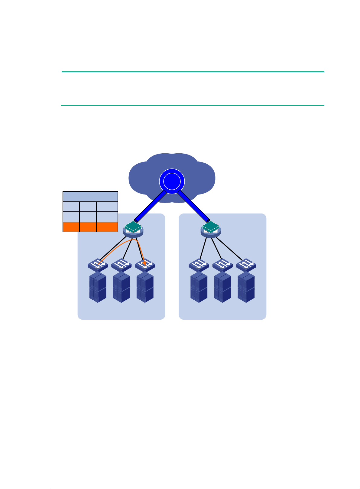
Unicast flow
For intra-site unicast flows, an edge device performs the typical MAC address table lookup, as
shown in Figure 4.
devices run EVI IS-IS in the control plane to establish adjacencies and advertise MAC
reachability information that has been learned or configured in the data plane to each other over
EVI links.
Figure 4
VLAN MAC Interface
Layer 2 forwarding in a site
MAC Table
200 MAC1 GE1/0/1
200 MAC2 GE1/0/2
GE1/0/1
Host A Host B
MAC1 MAC2
Site 1 Site 2
EVI
Transport network
EVI
EVI
GE1/0/2
The following forwarding process (see Figure 5) takes place for unicast flows betwee n sites:
1. The source edge device learns the source MAC address of the incoming Ethernet frame, and
looks up the destination MAC address in its MAC table for the outgoing interface .
2. If the outgoing interface is an EVI-Link interface instead of a physical port, the source edge
device encapsulates the frame in a GRE header, and then adds an IP header and a link layer
protocol header.
In the outer IP header, the source IP address is the source edge device's tunnel source IP
address, and the destination IP address is the destination edge device's tunnel source IP
address.
3. The source edge device forwards the encapsulated packet out of the EVI link to the destination
edge device across the IP transport network.
4. The destination edge device removes the headers of the original Ethernet fra me, looks up the
destination MAC address in the MAC address table, and sends the frame out of the matching
outgoing interface.
5
Page 9
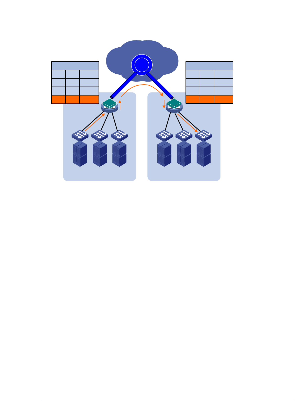
Figure 5 Layer 2 forwarding between sites
Transport network
VLAN MAC Interface
200 MAC1 GE1/0/1
200 MAC2 GE1/0/2
200 MAC3 EVI-Link0
Multicast flow
Edge devices run IPv4 IGMP snooping on each extended VLAN and learn multicast router port and
multicast member port information on EVI-Link interfaces for Layer 2 multicast forwarding as if they
were Ethernet interfaces. In an extended VLAN, each edge device tunnels IGMP, MLD, and PIM
protocol packets to all its remote edge devices, and the remote edge devices flood the packets in the
VLAN.
MAC Table
Host A
MAC1
EVI
c
EVI
a
Site 1 Site 2
b
Device A Device B
Host B
MAC2
EVI
d
GE1/0/1
MAC Table
VLAN MAC Interface
200 MAC1
200 MAC2
200 MAC3
e
Host C
MAC3
EVI-Link0
EVI-Link0
GE1/0/1
For a site-to-site multicast data frame in an extended VLAN, the following process (see Figure 6)
akes place:
t
1. The DR in a site sends out a multicast frame.
2. The source edge device copies the frame and encapsulates one copy on each multicast
member EVI-Link interface.
3. The source edge device unicasts the encapsulated frames to the de stination edge devices over
the EVI links.
4. Each destination edge device removes the headers of the multicast frame and copies the
multicast frame on each multicast member interface.
5. Each destination edge device sends the multicast frame out of all member interfaces to the
destination hosts.
6
Page 10
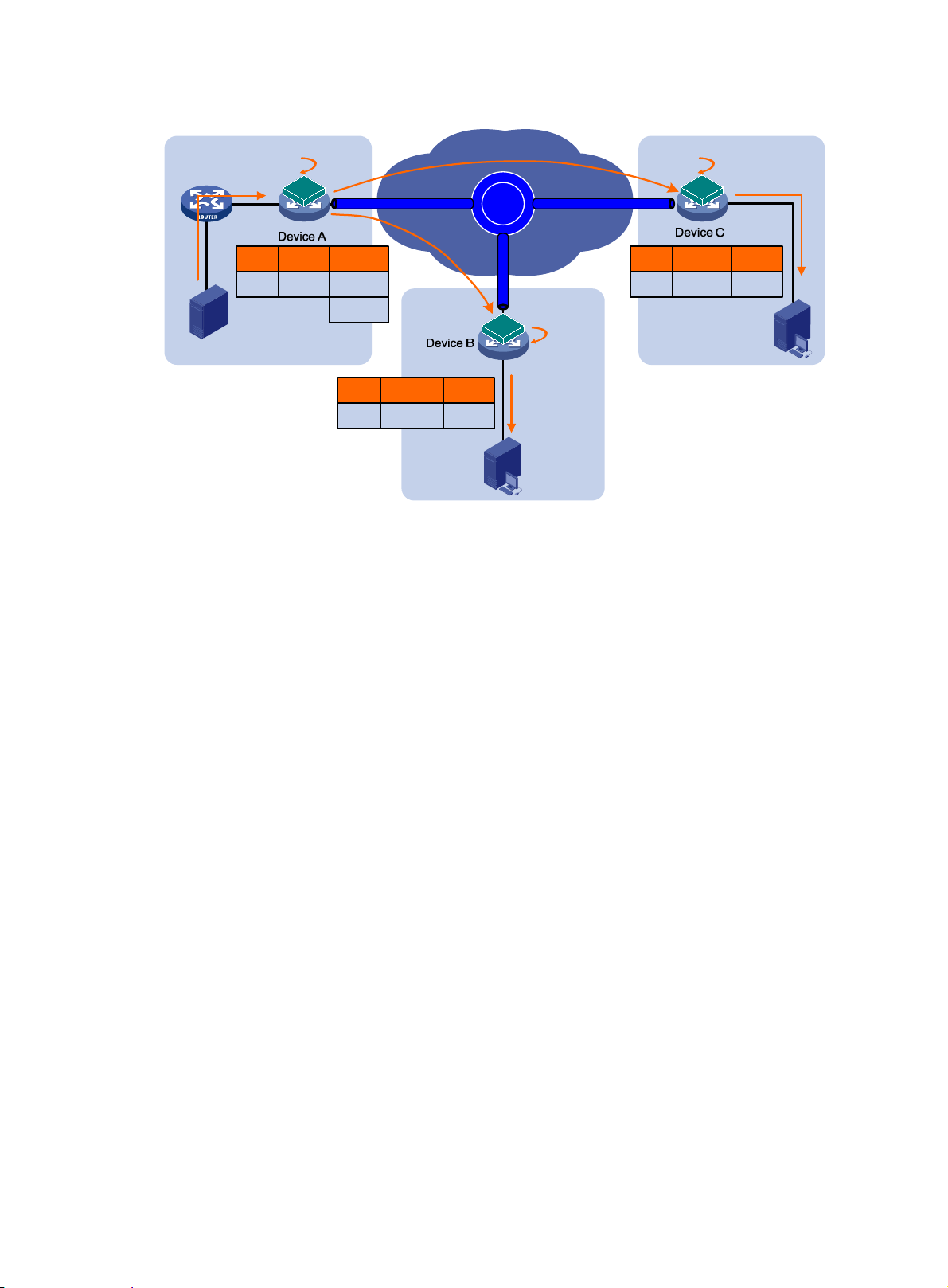
Figure 6 Multicast data frame forwarding process
(1) Multicast stream
DR
Site 1
Flooding flow
An edge device handles flooding by frame type, as follows:
• Broadcast frame—Floods the frame to all interfaces in the VLAN where the frame has been
received, including internal interfaces and EVI-Link interfaces. For ARP packets, you can use
the ARP flood suppression feature (see "ARP flood suppression"
• Destination-unknown unicast or multicast frame—Floods the frame to all internal interfaces
in the VLAN where the frame has been received. The edge device typically does not forward
destination-unknown frames to other sites. If a site-to-site flooding is desirable for a sp ecial
MAC address, use the selective flood feature (see "Selective flood").
(2) Replicate & encapsulate
EVI-Link1
EVI
GE1/0/1
VLAN R-port H-port
100 GE1/0/1 EVI-Link1
Source
EVI-Link2
EVI-Link2
VLAN R-port H-port
100 EVI-Link1 GE1/0/1
(3) Unicast
EVI-Link1
Site 2
(3) Unicast
EVI
EVI
GE1/0/1
(4) Decapsulate
& replicate
(5) Multicast
stream
Receiver
(4) Decapsulate & replicate
EVI-Link1
VLAN R-port H-port
100 EVI-Link1 GE1/0/1
Site 3
(5) Multicast stream
EVI
GE1/0/1
Receiver
) to reduce ARP broadcasts.
o flood a frame to remote sites, an EVI edge device must replicate the frame, encapsulate each
T
replica in one unicast frame for each destination site, and send the unicast frames to the remote
edge devices.
Placement of Layer 3 gateways
For the hosts in an extended VLAN at a site, their Layer 3 gateway must be on the edge device at the
local site rather than a remote site.
ARP flood suppression
ARP flood suppression reduces ARP request broadcasts on the EVI network by enabling edge
devices to reply to ARP requests on behalf of remote-site hosts.
As shown in Figure 7, this feature sn
ARP flood suppression table with remote MAC addresses. If an ARP request has a matching entry,
the local edge device replies to the request on behalf of the remote-site host. If no match is found, the
edge device floods the request to the EVI network.
ARP flood suppression uses the following workflow:
1. Host IP1 in site A sends an ARP request to obtain the MAC address of IP2.
2. Site A's edge device floods the ARP requests out of all interfaces, including the EVI tunnel
interfaces.
oops ARP replies on an EVI tunnel interface to populate the
7
Page 11
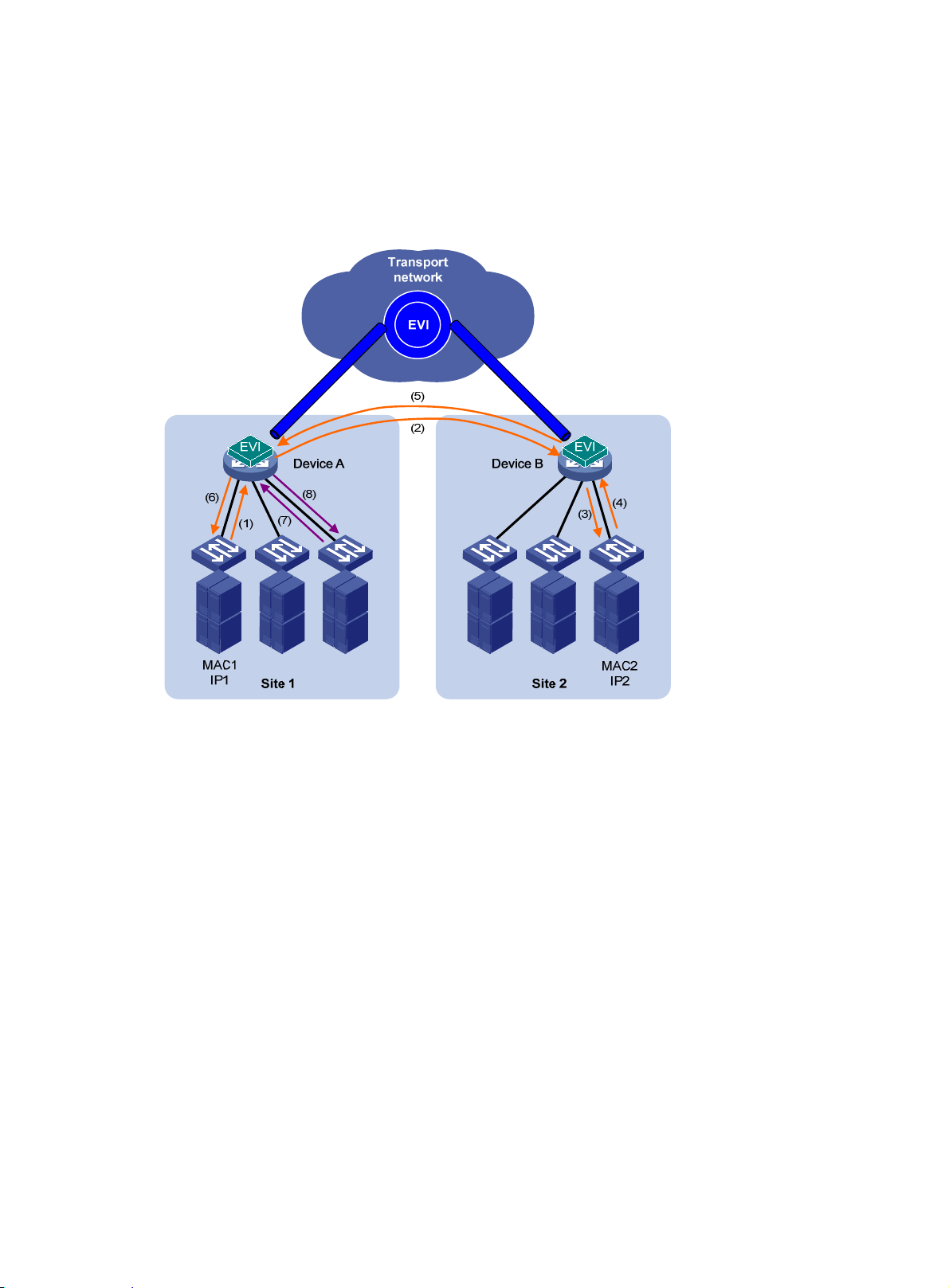
3. Site B's edge device de-encapsulates the ARP request and broadcasts the request.
4. IP2 sends an ARP reply back to site A's edge device over the EVI link.
5. Site A's edge device creates an ARP cache entry for the remote MAC address and forwa rds the
reply to the requesting host.
6. Site A's edge device replies to all subsequent requests for the MAC address of IP2.
Figure 7 ARP flood suppression
Selective flood
Selective flood enables an edge device to send an unknown unicast or multicast frame out of an EVI
tunnel interface.
This feature is designed for special multicast addresses that require flooding across sites but cannot
be added to a multicast forwarding table by IGMP snooping.
For example, you must configure selective flood for PIM hellos, IGMP general query packets, and
Microsoft NLBS cluster traffic to be sent out of an EVI tunnel interface.
Multihoming
EVI supports deploying two or more EVI edge devices to provide Layer 2 connectivity extension for a
site. Deployment of redundant edge devices creates the risk of loops because EVI edge devices do
not transmit spanning tree BPDUs across the transport network.
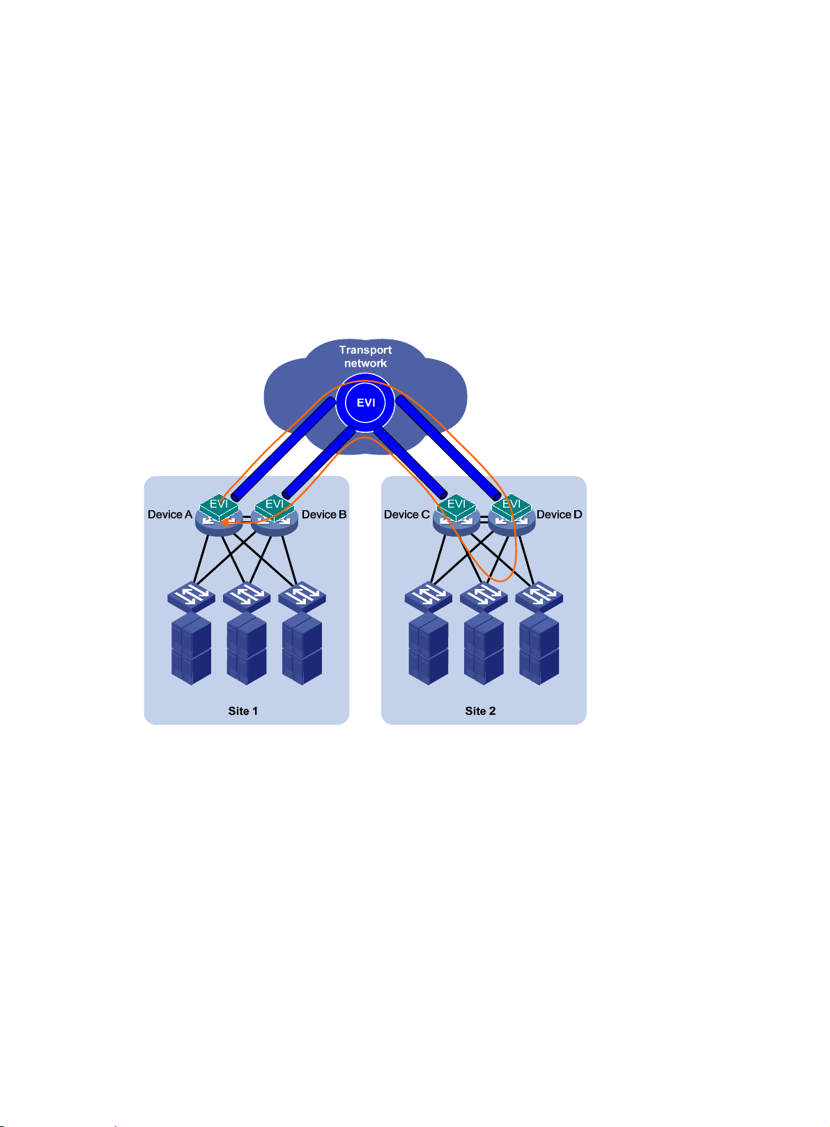
To remove loops in a multihomed network (see Figure 8), you
devices into one device, as shown in Figure 9. If
redundant edge devices to automatically designate each edge device as the traffic forwarder for a
particular set of extended VLANs, as shown in Figure 10.
The redun
DED for exchanging extended VLAN information and assigning active VLA Ns among them. All edge
dant edge devices exchange EVI IS-IS hello packets in a designated site VLAN to elect a
can use IRF to virtualize multiple edge
IRF is not used, EVI IS-IS runs among the
8
Page 12
devices have a user-configurable DED priority. The one with the highest DED priority is elected as
the DED. The DED uses the following rules to assign active VLANs:
1. If an extended VLAN is configured only on one edge device, the edge device is the appointed
edge forwarder for the VLAN.
2. If a set of extended VLANs is configured on at least two edge devices, the DED distributes the
extended VLANs equally among the edge devices.
3. When reassigning VLANs, the DED preferably assigns an edge device the active VLANs that
were assigned to it in the previous assignment.
The traffic forwarder designation mechanism of EVI IS-IS makes sure an extended VLAN is active
only on one edge device. For example, VLAN 1000 in Figure 10 is active only on site 1'
s Device B
and site 2's Device D. Only these two edge devices can receive or forward VLAN 1000 traffic
between the two sites.
Figure 8 Looped dual-homed EVI network
9
Page 13
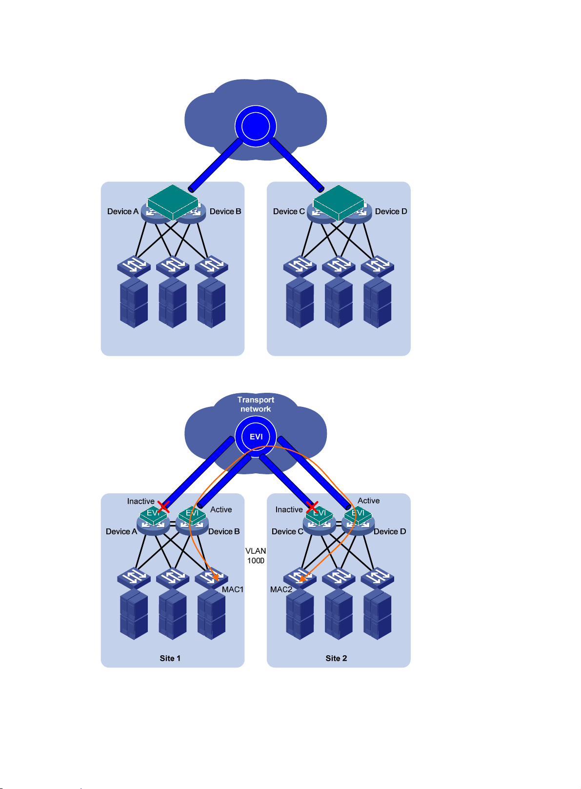
Figure 9 Edge devices in an IRF fabric
Transport
network
EVI
EVI
Site 1 Site 2
Figure 10 Active VLAN on an edge device
IRFIRF
EVI
10
Page 14

Path MTU
When encapsulating an Ethernet frame in EVI, the edge device does not modify the Ethernet frame,
but it sets the DF bit in the IP header. For an Ethernet transport network, the total size of an EVI
protocol packet increases by 46 bytes, and the total size of a data packet increases by 38 bytes.
Because EVI does not support path MTU discovery, your EVI deployment must make sure the path
MTU of the transport network is higher than the maximum size of EVI tunneled frames.
Licensing requirements
EVI requires a license. For information about feature licensing, see Fundamentals Configuration
Guide.
EVI configuration task list
Perform the following tasks on all edge devices of an EVI network:
Tasks at a glance Remarks
Configuring EVI basic features:
• (Required.) Configuring a site ID
• (Req
uired.) Configuring an EVI tunnel:
{ (Required.) Assigning a network ID to the EVI tunnel
{ (Required.) Specifying extended VLANs on the EVI tunnel
{ (Required.) Configuring ENDP
An EVI tunnel can provide services
for only one EVI network.
All edge devices in an EVI network
must have the same network ID.
The edge devices at the same site
must have the same site ID, and
the edge devices at different sites
must have different site IDs.
An extended VLAN can be
assigned only to one EVI network.
(Optional.) Tuning EVI IS-IS parameters
(Optional.) Configuring VLAN mappings N/A
(Optional.) Enabling EVI ARP flood suppression
(Optional.) Enabling EVI flooding for all destination-unknown frames
(Optional.) Enabling selective flood for a MAC address
Configuring EVI basic features
All tasks in this section are required for setting up an EVI network.
EVI IS-IS automatically runs on an
EVI tunnel interface immediately
after the interface is created.
You can tune EVI IS-IS
parameters for optimizing network
performance.
Perform this task to reduce ARP
request broadcasts on an EVI
network.
Perform this task to flood frames
with unknown MAC addresses to
the EVI tunnel interface.
Perform this task for special
multicast MAC addresses that
require Layer 2 inter-site
forwarding but cannot be learned
into the MAC address table.
11
Page 15

Configuring a site ID
A site ID uniquely identifies a site in an EVI network. Edge devices at the same site must use the
same site ID, and edge devices at different sites must use different site IDs.
A site ID conflict occurs in the following situations:
• The devices at the same site are assigned different site IDs.
• The devices at two different sites are assigned the same site ID.
When the site IDs of two devices conflict, EVI IS-IS isolates the device with the lower MAC address.
The isolated device can only receive EVI IS-IS hello packets. It cannot exchange EVI IS-IS packets
with other neighbors. To identify isolated devices, use the display evi isis brief command or the
display evi isis peer command.
To assign a site ID to the device:
Step Command Remarks
1. Enter system view.
2. Assign a site ID to the
device.
system-view
evi site-id
Configuring an EVI tunnel
Step Command Remarks
1. Enter system view.
2. Create an EVI tunnel
interface and enter tunnel
interface view.
system-view
interface tunnel
evi
N/A
site-id The default site ID is 0.
N/A
By default, no tunnel interface
exists.
The endpoints of a tunnel must use
number
mode
the same tunnel mode.
For more information about this
command, see tunneling
commands in Layer 3—IP Services
Command Reference.
12
Page 16

Step Command Remarks
By default, no source IP address or
source interface is specified for any
tunnel.
The source interface can be a Layer
3 Ethernet interface, Layer 3
aggregate interface, VLAN
interface, or Layer 3 loopback
interface. For more information
source
IMPORTANT:
command, see
3. Specify a source IP
address or interface for the
tunnel.
4. Configure the EVI link
keepalive interval and the
maximum number of
keepalive transmissions.
source
{ ipv4-address |
interface-type interface-number }
keepalive
[ seconds [ times ] ]
about the
tunneling commands in Layer 3—IP
Services Command Reference.
EVI uses the specified address or
the primary IP address of the
specified source interface as the
source IP address of tunneled
packets on the transport network.
EVI networks can share a tunnel
source IP address or interface.
To avoid forwarding failure, do not
use a GRE tunnel interface or its IP
address (configure with the ip
address command in tunnel
interface view) as the source
interface or IP address of an EVI
tunnel. For more information about
GRE, see Layer 3—IP Services
Configuration Guide.
By default, a keepalive packet is
sent every five seconds and the
maximum number of transmissions
is two.
If no reply is received from the
remote end on an EVI link after the
maximum number of keepalive
transmissions is reached, the local
end considers the EVI link as having
failed.
5. (Optional.) Generate a
GRE key for tunneled
packets based on their
VLAN IDs.
NOTE:
gre key vlan-id
In addition to the EVI-specific commands described in this section, you can config ure generic tunnel
interface commands on an EVI tunnel interface. These tunnel commands and tunneling b asics are
described in the tunneling configuration in Layer 3—IP Services Configuration Guide.
Assigning a network ID to the EVI tunnel
Assign the same network ID to the EVI tunnels of all edge devices in an EVI network.
13
By default, EVI tunneled packets do
not contain a GRE key.
The GRE key setting must be the
same across an EVI network.
Perform this step if any remote edge
devices generate VLAN ID-based
GRE keys for EVI tunneled packets.
Page 17

On an edge device, the network ID assigned to an EVI tunnel must be unique.
To assign a network ID to an EVI tunnel:
Step Command Remarks
1. Enter system view.
2. Enter tunnel interface view.
3. Specify a network ID.
system-view
interface tunnel
mode evi
[
evi network-id
]
N/A
number
number By default, no network ID is specified.
N/A
Specifying extended VLANs on the EVI tunnel
When configuring extended VLANs, follow these guidelines:
• You can specify an extended VLAN on only one EVI tunnel.
• To avoid loops, do not assign transport-facing ports to extended VLANs.
• To avoid data breach, make sure all edge devices in an EVI network maintain the same list of
extended VLANs.
To assign extended VLANs to an EVI tunnel:
Step Command Remarks
1. Enter system view.
2. Enter EVI tunnel interface
view.
3. Specify extended VLANs.
system-view
interface tunnel
mode evi
[
evi extend-vlan
]
number
vlan-list
N/A
N/A
By default, no VLANs are specified as
extended VLANs on any EVI tunnel.
To specify more extended VLANs, repeat
this step.
Configuring ENDP
ENDP enables the edge devices in an EVI network to discovery each other.
Configure an edge device as an ENDS to provide registration services or as an ENDC to register
with an ENDS.
Configuration guidelines
• For redundancy, you can configure up to two ENDSs on an EVI tunnel interface. These two
ENDSs work independently. The failure of one ENDS does not affect the neighbor discovery
and EVI link maintenance in the EVI network.
• When you enable ENDS on an EVI tunnel interface, an ENDC is automatically enabled. This
ENDC uses the source address of the EVI tunnel as the ENDS address. As a result, you can
use the evi neighbor-discovery client enable command to add only one ENDS address on an
ENDS-enabled EVI tunnel interface.
• To guarantee that each edge device can obtain the addresses of all its EVI neighbors, make
sure the ENDSs are the same across the EVI network.
• To improve security, enable ENDP authentication.
{ Make sure all authentication-enabled ENDCs and ENDSs in an EVI network u se the same
authentication key.
14
Page 18

{ If authentication is disabled on an ENDS, all ENDCs, including auth entication-enabled
ENDCs, can register with the ENDS without authentication.
{ If authentication is enabled on an ENDS, only authentication-enabled ENDCs that use the
same authentication key as the ENDS can register with the ENDS.
Configuring the edge device as an ENDS on the EVI tunnel
Step Command Remarks
1. Enter system view.
system-view
N/A
2. Enter EVI tunnel
interface view.
3. Enable ENDS.
4. (Optional.) Enable
ENDP authentication.
interface tunnel
mode evi ]
[
evi neighbor-discovery
server enable
evi neighbor-discovery
authentication { cipher
simple
} password
number
|
Configuring the edge device as an ENDC on the EVI tunnel
Step Command Remarks
1. Enter system view.
2. Enter EVI tunnel interface
view.
3. Configure the edge device
as the ENDC of an ENDS.
system-view
interface tunnel
mode evi ]
[
evi neighbor-discovery client
enable
server-ip
number
N/A
By default, ENDS is disabled.
On an ENDS-enabled tunnel interface,
you can use the
client enable
ENDS, and use the
neighbor-discovery client
register-interval
ENDC registration interval.
By default, ENDP authentication is
disabled.
N/A
N/A
By default, ENDC is disabled.
If ENDS is enabled on the EVI tunnel
interface, you can use this command
to specify only one more ENDS.
If ENDS is disabled, you can repeat
this command to specify up to two
ENDSs.
ENDS address is the tunnel source
address configured on an
ENDS-enabled EVI tunnel interface.
evi neighbor-discovery
command to add one more
evi
command to modify the
4. (Optional.) Enable ENDP
authentication.
5. Configure the interval at
which the ENDC updates
its registration with ENDSs.
evi neighbor-discovery
authentication { cipher
simple
} password
evi neighbor-discovery client
register-interval
time-value
Tuning EVI IS-IS parameters
EVI IS-IS automatically runs on an EVI link immediately after the link is set up. You can tune EVI
IS-IS parameters to optimize the protocol performance.
15
By default, ENDP authentication is
disabled.
|
All ENDSs and ENDCs in an EVI
network must use the same
authentication key.
By default, an ENDC update its
registration with an ENDS every 15
seconds.
Page 19

EVI IS-IS configuration task list
All EVI IS-IS configuration tasks are optional.
Tasks at a glance Remarks
Creating an EVI IS-IS process N/A
Changing the designated site VLAN
Optimizing an EVI IS-IS network:
• Configuring the EVI IS-IS hello interval
• Configuring the hello multiplier for calculating the
adjacency hold time
• Configuring the DED priority
• Configuring the CSNP packet transmit interval
• Configuring the minimum LSP transmit interval and
ximum number of LSPs sent at each interval
the ma
• Configuring the maximum LSP lifetime
• Configuring the LSP refresh interval
• Associating an EVI tunnel interface with a track entry
• Configuring preferred VLANs
The redundant edge devices at a site use the
designated site VLAN to exchange EVI IS-IS
hello packets for DED election and
extended-VLAN assignment.
Perform the EVI IS-IS
tasks to enable fast EVI link failure detection,
set appropriate MAC reachability information
update interval, and control the volume of LSP
and CSNP traffic on an EVI network.
network optimization
Specifying a routing policy for an EVI IS-IS process
Enabling adjacency change logging N/A
Configuring SNMP notifications and context for EVI IS-IS N/A
Configuring Graceful Restart for an EVI IS-IS process
Increasing the maximum number of MAC entries in an
LSP for an EVI IS-IS process
Creating an EVI IS-IS process
Each EVI network has one EVI IS-IS process. Before you can configure settings in EVI IS-IS process
view, you must create the pro ce ss.
An EVI IS-IS process is created automatically when you perform any one of the following tasks on a
tunnel interface:
• Specify extended VLANs.
• Perform network optimization tasks (see "Optimizing an EVI IS-IS network"
the LSP refresh interval and the maximum LSP lifetime.
• Configure VLAN mappings.
Perform this task to advertise a subset of MAC
addresses instead of all local MAC addresses
to remote sites.
Perform this task for providing nonstop
services.
Perform this task depending on the MAC
address table size on the edge device.
) except configuring
The ID of an automatically created process is the same as the EVI tunnel interface number.
Alternatively, you can use the evi-isis command to create an EVI IS-IS process manually.
To delete a manually created EVI IS-IS process, you must use the undo evi-isis command.
• If EVI IS-IS settings exist on the EVI tunnel interface, the undo evi-isis command only deletes
settings configured in EVI IS-IS process view.
16
Page 20

• If no EVI IS-IS settings exist on the EVI tunnel interface, the undo evi-isis command deletes
both the EVI IS-IS process and all settings configured in EVI IS-IS process view.
An automatically created EVI IS-IS process is automatically deleted when you delete all EVI IS-IS
settings from the EVI tunnel interface.
To create an EVI IS-IS process or enter its view:
Step Command Remarks
1. Enter system view.
2. Create an EVI IS-IS process
or enter EVI IS-IS process
view.
system-view
evi-isis
process-id
Changing the designated site VLAN
EVI IS-IS uses the designated site VLAN to exchange hello packets within a site to discover
redundant edge devices and map extended VLANs to edge devices.
This designated site VLAN must not be extended across any EVI network.
N/A
By default, no EVI IS-IS process is
configured.
The process ID you specify must be the
same as the EVI tunnel interface number.
The EVI IS-IS process takes effect after you
configure extended VLANs on the tunnel
interface.
To change the designated site VLAN for EVI IS-IS:
Step Command Remarks
1. Enter system view.
2. Specify a designated site
VLAN.
system-view
evi designated-vlan
Optimizing an EVI IS-IS network
Perform the tasks in this section to optimize an EVI IS-IS network for bandwidth efficiency and high
performance.
Configuring the EVI IS-IS hello interval
EVI edge devices send EVI IS-IS hellos over EVI links to establish and maintain adjacencies and
elect the inter-site DED on each EVI link.
EVI edge devices at a multihomed site also exchange EVI IS-IS hellos to elect the site DED for
distributing extended VLANs among them.
Set the hello interval depending on the network convergence requirement and system resources.
• To increase the speed of network convergence, decrease the hello interval.
• To conserve resources, increase the hello interval.
vlan-id
N/A
The default designated site
VLAN is VLAN 1.
NOTE:
The hello interval of a DED is one-third of the hello interval set with the evi isis timer hello
command.
To configure the EVI IS-IS hello interval on an EVI tunnel interface:
17
Page 21

Step Command Remarks
1. Enter system view.
system-view
N/A
2. Enter EVI tunnel interface
view.
3. Configure the EVI IS-IS
hello interval.
interface tunnel
evi ]
evi isis timer hello
number [
seconds
mode
N/A
The default hello interval is 10
seconds.
If the edge device is a DED, its hello
interval is one-third of the hello
interval set with this command.
Configuring the hello multiplier for calculating the adjacency hold time
Adjacency hold time sets the amount of time that the remote edge devices can retain the adjac ency
with the local edge device before an adjacency update.
• If Graceful Restart is disabled, the adjacency hold time equals the EVI IS-IS hello interval
multiplied by the hello multiplier.
• If Graceful Restart is enabled, the adjacency hold time equals the greater value between the
following settings:
{ The restart interval.
{ The EVI IS-IS hello interval multiplied by the hello multiplier.
Edge devices send their adjacency hold time in hello packets to update the adjacencies with their
neighbors. An edge device removes the adjacency with a neighbor if it does not receive a hello
packet from the neighbor before the timer expires.
To configure the multiplier for calculating the adjacency hold time on an EVI tunnel interface:
Step Command Remarks
1. Enter system view.
2. Enter EVI tunnel interface
view.
3. Configure the multiplier
for calculating the
adjacency hold time.
Configuring the DED priority
The edge devices on an EVI link exchange their DED priority in EVI IS-IS hello packets to elect the
inter-site DED for periodic LSDB synchronization. You can use the evi isis timer csnp command to
change the synchronization interval.
The edge devices at a multihomed site exchange their DED priority in EVI IS-IS hello packets to elect
the site DED for distributing extended VLANs among them.
The edge device with higher DED priority is more likely to be elected as a site DED or inter-site DED.
If two edge devices have the same DED priority, the device with the highest MAC address is elected.
To configure the DED priority of the edge device on an EVI tunnel interface:
Step Command Remarks
1. Enter system view.
system-view
interface tunnel
evi ]
evi isis timer
holding-multiplier
system-view
number [
value
mode
N/A
N/A
The default multiplier is 3.
The maximum adjacency hold time is
65535 seconds. If this value is
exceeded, the actual adjacency hold
time is set to 65535 seconds.
N/A
18
Page 22

Step Command Remarks
2. Enter EVI tunnel interface view.
interface tunnel
mode evi ]
[
number
N/A
3. Configure the DED priority.
evi isis ded-priority
value The default DED priority is 64.
Configuring the CSNP packet transmit interval
This configuration takes effect only on DEDs.
The DEDs in an EVI network regularly send CSNP packets to advertise LSP summaries for LSDB
synchronization.
To configure the CSNP packet transmit interval on a DED:
Step Command Remarks
1. Enter system view.
2. Enter tunnel interface view.
3. Configure the CSNP packet
transmit interval.
system-view
interface tunnel
mode evi ]
[
evi isis timer csnp
number
seconds
N/A
N/A
By default, a DED sends CSNP
packets every 10 seconds.
Configuring the minimum LSP transmit interval and the maximum number of LSPs sent at each interval
The edge device generates an LSP update when any LSDB content changes. For example, a MAC
address is removed or added.
To control EVI IS-IS LSP traffic on the EVI network:
Step Command Remarks
1. Enter system view.
2. Enter EVI tunnel interface view.
3. Configure the minimum LSP
transmit interval and the
maximum number of LSP
segments sent at each interval.
Configuring the maximum LSP lifetime
EVI edge devices add a lifetime in each LSP they have advertised, and update LSPs regularly or
when MAC reachability information changes. If an edge device does not receive an update for an
LSP before the lifetime expires, the edge device removes the LSP from the LSDB and removes the
MAC addresses advertised through the LSP from the data plane.
To specify the maximum lifetime of the LSPs generated by an EVI IS-IS process:
Step Command Remarks
1. Enter system view.
system-view
interface tunnel
mode evi ]
[
evi isis timer lsp
count ]
system-view
number
time [
count
N/A
N/A
By default, the minimum LSP
transmit interval is 100
milliseconds, and a maximum of
five LSP segments can be sent at
each interval.
Before the minimum transmit
interval is reached, the EVI
tunnel interface cannot send LSP
segments.
N/A
19
Page 23

Step Command Remarks
2. Enter EVI IS-IS process view.
evi-isis
process-id
N/A
3. Configure the maximum LSP
lifetime.
timer lsp-max-age
seconds
Configuring the LSP refresh interval
The edge device sends LSP updates at the refresh interval to update MAC reachability information.
To change the LSP refresh interval:
Step Command Remarks
1. Enter system view.
2. Enter EVI IS-IS process view.
3. Configure the LSP refresh
interval.
system-view
evi-isis
timer lsp-refresh
process-id
seconds
Associating an EVI tunnel interface with a track entry
The default maximum LSP
lifetime is 1200 seconds.
N/A
N/A
The default LSP refresh interval is 900
seconds.
The minimum LSP transmit interval and
the maximum number of LSPs sent at
each interval can affect the actual LSP
refresh interval.
To avoid unnecessary age-outs,
appropriately set the LSP refresh
interval and the LSP lifetime.
EVI IS-IS uses a hello mechanism to monitor the connectivity of each EVI link on an EVI tunnel. To
detect the connectivity of a particular EVI link more quickly, you can associate its tunnel interface
with a track entry. The monitoring protocol used in this entry can only be BFD.
EVI IS-IS changes the state of an EVI-Link interface in response to the track entry state, as shown
in Table 1.
Table 1
Action on the monitored EVI-Link in response to the track entry state change
Track entry state State of the monitored EVI link
Positive The EVI link is operating correctly.
Negative The EVI link has failed.
The EVI link is not monitored.
This situation occurs when the Track
module or the monitoring module is not
NotReady
ready (for example, the Track module is
restarting or the monitoring settings are
incomplete). In this situation, EVI cannot
obtain information about the EVI link from
the Track module.
Action on the EVI-Link
interface
Places the EVI-Link interface in up
state.
Places the EVI-Link interface in
down state.
N/A
For more information about configuring a track entry, see Track configuration in High Availability
Configuration Guide.
To associate an EVI tunnel interface with a track entry:
20
Page 24

Step Command Remarks
1. Enter system view.
system-view
N/A
2. Enter EVI tunnel interface
view.
3. Associate a track entry with
the tunnel interface.
Configuring preferred VLANs
At a dual-homed site, specify an extended VLAN as a preferred VLAN on the edge device you prefer
to use as the appointed forwarder for the VLAN. The DED assigns an edge device its preferred
VLANs as long as possible. If an extended VLAN is configured as a preferred VLAN on both edge
devices, the DED uses the typical VLAN distribution rules to distribute the VLAN. For information
about typical extended VLAN distribution, see "Multihoming."
After you remove the preferred VLAN configuration on an edge device, the DED continues to assign
the VLAN to the edge device if the following requirements are met:
• The EVI tunnel interface on the edge device is up.
• The VLAN has not been configured as a preferred VLAN on another edge device.
IMPORTANT:
For a preferred VLAN to take effect, you must make sure it has been specified as an extended
VLAN.
To configure preferred VLANs:
interface tunnel
evi ]
evi isis track
track-entry-number
number [
mode
N/A
By default, an EVI tunnel interface
is not associated with any track
entry.
You can associate an EVI tunnel
interface with only one track entry.
Step Command Remarks
1. Enter system view.
2. Enter EVI tunnel interface
view.
3. Specify preferred VLANs.
system-view
interface tunnel
evi ]
evi isis preferred-vlan
number [
mode
vlan-list
N/A
N/A
By default, no preferred VLANs
are configured.
Repeat this command to add
additional preferred VLANs.
Specifying a routing policy for an EVI IS-IS process
You can configure a routing policy to match MAC reachability information that can be advertised to
the remote EVI sites. The routing policy is also called a reachability information filtering policy.
The routing policy for EVI IS-IS can only contain the following filters:
• MAC list.
• VLAN list.
For more information about configuring routing policies, see Layer 3—IP Routing Configuration
Guide.
To specify a routing policy for an EVI IS-IS process:
21
Page 25

Step Command Remarks
1. Enter system view.
system-view
N/A
2. Enter EVI IS-IS process view.
3. Specify a routing policy for the EVI
IS-IS process.
evi-isis
filter-policy
process-id
policy-name
Enabling adjacency change logging
Adjacency change logging enables an EVI IS-IS process to send a log message to the information
center when an adjacency change occurs. With the information center, you can set log message
filtering and output rules, including output destinations. For more information about using the
information center, see Network Management and Monitoring Configuration Guide.
To enable adjacency change logging:
Step Command Remarks
1. Enter system view.
2. Enter EVI IS-IS process view.
3. Enable adjacency change logging.
system-view
evi-isis
log-peer-change enable
process-id
N/A
By default, an EVI IS-IS process is
not associated with any routing
policy.
N/A
N/A
By default, adjacency change
logging is enabled.
Configuring SNMP notifications and context for EVI IS-IS
To report critical EVI IS-IS events to an NMS, enable SNMP notifications for EVI IS-IS. For EVI IS-IS
event notifications to be sent correctly, you must also configure SNMP as described in Network
Management and Monitoring Configuration Guide.
In addition to the private EVI IS-IS MIB, EVI IS-IS shares the standard IS-IS MIB with IS-IS and other
protocols that use IS-IS in the control plane. For SNMP to correctly identify a protocol's management
information in the standard IS-IS MIB, you must configure a unique context for each of these
protocols. If a protocol supports multiple processes, you must assign a unique context to each
process.
The context names must be unique among all the protocols and their processes.
Context is a method introduced to SNMPv3 for multiple-instance management. For SNMPv1/v2c,
you must specify a context name as a community name for protocol identification.
To configure SNMP notifications and context for an EVI IS-IS process:
Step Command Remarks
1. Enter system view.
system-view
N/A
22
Page 26

Step Command Remarks
2. Enable EVI IS-IS
notifications.
3. Enter EVI IS-IS process
view.
4. Configure an SNMP
context name for EVI
IS-IS.
snmp-agent trap enable evi-isis
adjacency-state-change
[
area-mismatch
id-length-mismatch
lsp-parse-error
|
max-seq-exceeded
maxarea-mismatch
own-lsp-purge
rejected-adjacency
skip-sequence-number
topology-change
evi-isis
snmp context-name
process-id
buffsize-mismatch
|
link-disconnect
|
lsp-size-exceeded
|
|
new-ded
|
protocol-support
|
|
|
version-skew
|
context-name
|
|
|
By default, all EVI IS-IS
|
] *
notifications are enabled.
|
N/A
By default, no SNMP context
name is configured for EVI
IS-IS.
Configuring Graceful Restart for an EVI IS-IS process
Enable Graceful Restart for the peer EVI IS-IS processes at two ends of an EVI tunnel to guarantee
nonstop forwarding while the peer EVI IS-IS processes are re-establishing their adjacency after a
process restart or active/standby switchover occurs.
If Graceful Restart is enabled, the adjacency hold time equals the greater value between the
following settings:
• The restart interval.
• The EVI IS-IS hello interval multiplied by the hello multiplier .
If the edge device is a DED, its hello interval is one-third of the hello interval set by using the evi isis
timer hello command.
To configure Graceful Restart for an EVI IS-IS process:
Step Command Remarks
1. Enter system view.
2. Enter EVI IS-IS process view.
3. Enable Graceful Restart.
4. Configure the restart interval.
system-view
evi-isis
graceful-restart
graceful-restart interval
interval-value
process-id
N/A
N/A
By default, EVI IS-IS Graceful Restart
is disabled.
The default restart interval is 300
seconds.
If the restarting EVI process fails to
complete re-establishing the
adjacency with the peer EVI process,
the EVI link goes down.
Increasing the maximum number of MAC entries in an LSP for an EVI IS-IS process
An EVI IS-IS process advertises all local MAC reachability information in one LSP. By default, an
LSP can convey up to 55 x 2
10
MAC address entries.
23
Page 27

T o increase this num ber to accommodate all local MAC address entries, create virtual systems. Each
virtual system represents an increase of 55 x 2
10
MAC address entries. If n virtual systems are
created, the maximum number of MAC address entries in an LSP is (n+1) x 55 x 2
To configure EVI IS-IS virtual system:
Step Command Remarks
1. Enter system view.
2. Enter EVI IS-IS process
view.
3. Create an EVI IS-IS virtual
system.
system-view
evi-isis
virtual-system
systemid
process-id
Configuring VLAN mappings
If two sites use different VLANs to convey the same service, you can configure a mapping between
the VLANs at the two sites.
For example, site 1 uses VLAN 100 and site 2 uses VLAN 200 to transmit data service. At site 1, map
VLAN 100 to VLAN 200. At site 2, map VLAN 200 to VLAN 100. When the edge device at site 1
receives MAC addresses from site 2 in VLAN 200, it adds the MAC addresses to VLAN 100
automatically . Likewise, when the edge device at site 2 receives MAC addresses from site 1 in VLAN
100, it adds the MAC addresses to VLAN 200 automatically.
10
.
N/A
N/A
By default, no EVI IS-IS virtual systems are
created.
IMPORTANT:
The virtual system ID must be unique in the
EVI network.
In the mapping at site 1, VLAN 100 is the local VLAN, and VLAN 200 is the remote VLAN.
At a site, a VLAN can have only one mapping for a remote site. The local site considers a remote
VLAN invalid if the remote VLAN has the same VLAN ID as the local VLAN in a mapping. The local
site drops the MAC addresses received from the remote site in the VLAN. In the previous example,
site 1 will drop a MAC address received from site 2 if the address is in VLAN 100.
To map a local VLAN to a remote VLAN:
Step Command Remarks
1. Enter system view.
2. Enter EVI tunnel interface
view.
3. Map a local VLAN to a
remote VLAN.
system-view
interface tunnel
number [
evi vlan-mapping
local-vlan-id
remote-vlan-id [
site-id ]
mode evi
translated
site
]
N/A
N/A
By default, no VLAN mappings are
configured.
Enabling EVI ARP flood suppression
Step Command Remarks
1. Enter system view.
system-view
N/A
24
Page 28

Step Command Remarks
To avoid traffic blackholes,
2. Verify that the MAC aging
timer is longer than the EVI
ARP entry aging timer.
3. (Optional.) Set the MAC aging
timer.
4. Enter EVI tunnel interface
view.
5. Enable EVI ARP flood
suppression.
6. (Optional.) Display EVI ARP
flood suppression entries.
display mac-address aging-time
mac-address timer
interface tunnel
evi ]
evi arp-suppression enable
• In standalone mode:
display evi arp-suppression
interface tunnel
interface-number [ vlan
vlan-id ] [ count ]
• In IRF mode:
display evi arp-suppression
interface tunnel
interface-number [ vlan
vlan-id ] [ slot slot-number ]
[ count ]
number [
mode
make sure the MAC aging
timer is longer than the EVI
ARP entry aging timer (fixed
at 15 minutes) on all edge
devices.
The default MAC aging timer
is 300 seconds.
Perform this step if the MAC
aging timer is shorter than the
EVI ARP entry aging timer.
N/A
By default, EVI ARP flood
suppression is disabled.
display
The
available in any view.
commands are
Enabling EVI flooding for all destination-unknown frames
By default, the device floods unknown unicast and multicast frames only to internal interfaces. EVI
flooding enables the device to flood all destination-unknown frames to an EVI tunnel interface.
To enable EVI flooding for all destination-unknown frames:
Step Command Remarks
1. Enter system view.
2. Enter EVI tunnel
interface view.
3. Enable EVI flooding.
system-view
interface tunnel
mode evi ]
[
evi flooding enable
number
N/A
N/A
By default, EVI flooding is disabled.
Enabling selective flood for a MAC address
CAUTION:
Do not configure selective flood for local unicast MAC addresses. The setting might cause remote
devices to drop packets destined for the MAC address.
By default, the device floods unknown unicast and multicast frames only to internal interfaces.
25
Page 29

If an application uses a special multicast address that requires flooding across sites and cannot be
added to a multicast forwarding table by IGMP snooping, enable selective flood for the multicast
address.
To enable selective flood for a MAC address:
Step Command Remarks
1. Enter system view.
2. Enter EVI tunnel interface
view.
3. Enable selective flood for the
MAC address in a set of
VLANs.
system-view
interface tunnel
evi ]
evi selective-flooding
mac-address
vlan-id-list
N/A
number [
mac-address
Displaying and maintaining EVI
Execute display commands in any view and reset commands in user view.
Task Command
On an ENDS, display ENDS
information.
display evi neighbor-discovery server summary
mode
vlan
N/A
By default, selective flood is
disabled for all MAC addresses.
On an ENDS, display neighbors that
have registered with the ENDS.
On an ENDS, display ENDS statistics.
Display ENDC information.
Display neighbors that an ENDC has
learned.
Display ENDC statistics.
Display EVI-Link interface information
for an EVI tunnel.
Display information about EVI-Link
interfaces.
Display brief EVI IS-IS process
information.
Display local MAC addresses.
display evi neighbor-discovery server member
tunnel
interface-number | [
vpn-instance
[
display evi neighbor-discovery server statistics interface
tunnel
interface-number
display evi neighbor-discovery client summary
display evi neighbor-discovery client member
tunnel
interface-number | [
server
server-ip ] [
display evi neighbor-discovery client statistics interface
tunnel
interface-number
display evi link interface tunnel
display interface
description
[
display evi isis brief
display evi isis local-mac
tunnel
interface-number [
count
[
] ]
display evi isis local-mac nonadvertised
interface-number [
vpn-instance-name ] ]
vpn-instance
evi-link
[
down
|
vlan
local
local-ip |
local
local-ip |
vpn-instance-name ] ]
interface-number
[ interface-number ] ] [
] ]
[ process-id ]
{
vlan
vlan-id ] [
dynamic
vlan-id ] [
count
|
remote
remote
static
filtered
[
] ]
interface
[
client-ip ]
interface
[
client-ip |
brief
interface
} [
passed
|
interface tunnel
]
Display remote MAC addresses.
Display EVI IS-IS link state database.
Display EVI IS-IS neighbors.
display evi isis remote-mac
interface-number [
display evi isis lsdb
[ process-id ]
display evi isis peer
26
vlan
vlan-id ] [
local | lsp-id
[
[ process-id ]
interface tunnel
[
count
] ]
lspid |
verbose
] *
Page 30

Task Command
Display EVI IS-IS information for a
tunnel interface.
display evi isis tunnel
[ tunnel-number ]
Display EVI IS-IS GR state.
Display remote MAC addresses (in
standalone mode).
Display remote MAC addresses (in IRF
mode).
Display EVI ARP flood suppression
entries (in standalone mode).
Display EVI ARP flood suppression
entries (in IRF mode).
Display VLAN mappings for EVI.
Clear data for EVI IS-IS processes.
Clear EVI ARP flood suppression
entries.
display evi isis graceful-restart status
display evi mac-address interface tunnel
vlan
[
vlan-id ] [
display evi mac-address interface tunnel
mac-address
display evi mac-address interface tunnel
vlan
[
vlan-id ] [
display evi mac-address interface tunnel
mac-address
display evi arp-suppression interface tunnel
interface-number [
display evi arp-suppression interface tunnel
interface-number [
display evi vlan-mapping
reset evi isis all
reset evi arp-suppression interface tunnel
vlan
[
vlan-id ]
EVI configuration examples
count
]
mac-address
slot
slot-number ] [
mac-address
vlan
vlan-id ] [
vlan
vlan-id ] [
[ process-id ]
vlan
vlan-id
count ]
vlan
vlan-id [
count
slot
slot-number ] [
[ process-id [
[ process-id ]
interface-number
interface-number
interface-number
interface-number
slot
slot-number ]
]
vlan
vlan-id ] ]
interface-number
count ]
Single-homed EVI network configuration example
Network requirements
As shown in Figure 11.
• Use EVI to extend VLANs 21 through 100 across site 1, site 2, and site 3 over an IPv4 network.
• Use network ID 1 to identify the EVI network.
• Use Device A as an ENDS and all other edge devices as ENDCs for neighbor discovery.
• Map site 1's VLAN 80 to site 2's VLAN 21 to convey the same service across the two sites.
• Configure a routing policy on Device A to advertise MAC addresses in VLANs 21 to 90 to the
remote sites.
27
Page 31

Figure 11 Network diagram
Device A Device B
Tunnel0
Configuration procedure
1. Configure routes for the sites to reach each other. (Details not shown.)
2. Configure Device A:
# Configure the site ID.
<DeviceA> system-view
[DeviceA] evi site-id 1
# Assign an IP address to the transport-facing interface GigabitEthernet 1/0/1.
[DeviceA] interface gigabitethernet 1/0/1
[DeviceA-GigabitEthernet1/0/1] ip address 1.1.1.1 24
[DeviceA-GigabitEthernet1/0/1] quit
# Create an IPv4 EVI tunnel interface.
[DeviceA] interface tunnel 0 mode evi
# Set the network ID to 1 for the EVI tunnel interface.
[DeviceA-Tunnel0] evi network-id 1
# Specify the IP address of GigabitEthernet 1/0/1 as the source IP of the EVI tunnel.
[DeviceA-Tunnel0] source 1.1.1.1
# Set the tunnel keepalive interval to 20 seconds and the maximum number of tra nsmissions to
2.
[DeviceA-Tunnel0] keepalive 20 2
# Specify extended VLANs on the EVI tunnel interface.
[DeviceA-Tunnel0] evi extend-vlan 21 to 100
# Configure Device A as an ENDS on the EVI tunnel interface.
[DeviceA-Tunnel0] evi neighbor-discovery server enable
# Map VLAN 80 to site 2's VLAN 21 on Tunnel 0.
[DeviceA-Tunnel0] evi vlan-mapping 80 translated 21 site 2
[DeviceA-Tunnel0] quit
# Configure the routing policy EVI-Filter to match MAC addresses in VLANs 21 to 90.
[DeviceA] route-policy EVI-Filter permit node 10
[DeviceA-route-policy-EVI-Filter-10] if-match vlan 21 to 90
GE1/0/1
1.1.1.1/24
GE1/0/1
1.1.3.1/24
IP network
EVI
Tunnel0
Device C
GE1/0/1
1.1.2.1/24
Tunnel0
28
Page 32

[DeviceA-route-policy-EVI-Filter-10] quit
# Assign the policy to EVI IS-IS process 0.
[DeviceA] evi-isis 0
[DeviceA-evi-isis-0] filter-policy EVI-Filter
[DeviceA-evi-isis-0] quit
3. Configure Device B:
# Configure the site ID.
<DeviceB> system-view
[DeviceB] evi site-id 2
# Assign an IP address to the transport-facing interface GigabitEthernet 1/0/1.
[DeviceB] interface gigabitethernet 1/0/1
[DeviceB-GigabitEthernet1/0/1] ip address 1.1.2.1 24
[DeviceB-GigabitEthernet1/0/1] quit
# Create an IPv4 EVI tunnel interface.
[DeviceB] interface tunnel 0 mode evi
# Set the network ID to 1 for the EVI tunnel interface.
[DeviceB-Tunnel0] evi network-id 1
# Specify the IP address of GigabitEthernet 1/0/1 as the source IP of the EVI tunnel.
[DeviceB-Tunnel0] source 1.1.2.1
# Set the tunnel keepalive interval to 20 seconds and the maximum number of tra nsmissions to
2.
[DeviceB-Tunnel0] keepalive 20 2
# Specify extended VLANs on the EVI tunnel interface.
[DeviceB-Tunnel0] evi extend-vlan 21 to 100
# Configure Device B as an ENDC of Device A.
[DeviceB-Tunnel0] evi neighbor-discovery client enable 1.1.1.1
# Map VLAN 21 to site 1's VLAN 80 on Tunnel 0.
[DeviceB-Tunnel0] evi vlan-mapping 21 translated 80 site 1
[DeviceB-Tunnel0] quit
4. Configure Device C:
# Configure the site ID.
<DeviceC> system-view
[DeviceC] evi site-id 3
# Assign an IP address to the transport-facing interface GigabitEthernet 1/0/1.
[DeviceC] interface gigabitethernet 1/0/1
[DeviceC-GigabitEthernet1/0/1] ip address 1.1.3.1 24
[DeviceC-GigabitEthernet1/0/1] quit
# Create an IPv4 EVI tunnel interface.
[DeviceC] interface tunnel 0 mode evi
# Set the network ID to 1 for the EVI tunnel interface.
[DeviceC-Tunnel0] evi network-id 1
# Specify the IP address of GigabitEthernet 1/0/1 as the source IP of the EVI tunnel.
[DeviceC-Tunnel0] source 1.1.3.1
# Set the tunnel keepalive interval to 20 seconds and the maximum number of tra nsmissions to
2.
[DeviceC-Tunnel0] keepalive 20 2
# Specify extended VLANs on the EVI tunnel interface.
29
Page 33

[DeviceC-Tunnel0] evi extend-vlan 21 to 100
# Configure Device C as an ENDC of Device A.
[DeviceC-Tunnel0] evi neighbor-discovery client enable 1.1.1.1
[DeviceC-Tunnel0] quit
Verifying the configuration
1. Verify the configuration on Device A:
# Display information about the EVI tunnel interface.
[DeviceA] display interface tunnel 0
Tunnel0
Current state: UP
Line protocol state: UP
Description: Tunnel0 Interface
Bandwidth: 64kbps
Maximum Transmit Unit: 64000
Internet protocol processing: disabled
Tunnel source 1.1.1.1
Tunnel keepalive enabled, Period(20 s), Retries(2)
Network ID 1
Tunnel protocol/transport GRE_EVI/IP
Output queue - Urgent queuing: Size/Length/Discards 0/100/0
Output queue - Protocol queuing: Size/Length/Discards 0/500/0
Output queue - FIFO queuing: Size/Length/Discards 0/75/0
Last clearing of counters: Never
Last 300 seconds input rate: 0 bytes/sec, 0 bits/sec, 0 packets/sec
Last 300 seconds output rate: 0 bytes/sec, 0 bits/sec, 0 packets/sec
Input: 0 packets, 0 bytes, 0 drops
Output: 0 packets, 0 bytes, 0 drops
# Display information about EVI-Link interfaces.
[DeviceA] display evi link interface tunnel 0
Interface Status Source Destination
EVI-Link0 UP 1.1.1.1 1.1.2.1
EVI-Link1 UP 1.1.1.1 1.1.3.1
# Display ENDS information.
[DeviceA] display evi neighbor-discovery server summary
Interface Local Address Network ID Auth Members Vpn-instance
Tunnel0 1.1.1.1 1 disabled 3 [No Vrf]
# Display ENDC information.
[DeviceA] display evi neighbor-discovery client summary
Status: I-Init E-Establish P-Probe
Interface Local Address Server Address Network ID Reg Auth Status Vpn-instance
Tunnel0 1.1.1.1 1.1.1.1 1 15 disabled E [No Vrf]
# Display EVI neighbors registered with the ENDS.
[DeviceA] display evi neighbor-discovery server member
Interface: Tunnel0 Network ID: 1 Vpn-instance: [No Vrf]
IP Address: 1.1.1.1
Client Address System ID Expire Created Time
1.1.1.1 000F-0001-0001 25 2013/01/01 00:00:43
30
Page 34

1.1.2.1 000F-0001-0002 15 2013/01/01 01:00:46
1.1.3.1 000F-0001-0003 20 2013/01/01 01:02:13
# Display neighbor entries that Device A has learned.
[DeviceA] display evi neighbor-discovery client member
Interface: Tunnel0 Network ID: 1 Vpn-instance: [No Vrf]
Local Address: 1.1.1.1
Server Address: 1.1.1.1
Neighbor System ID Created Time Expire Status
1.1.2.1 000F-0001-0002 2013/01/01 12:12:12 13 Up
1.1.3.1 000F-0001-0003 2013/01/01 12:12:12 12 Up
# Display VLAN mappings for EVI.
[DeviceA] display evi vlan-mapping
VLAN mappings for EVI IS-IS(0)
Local-VID Peer-ID Remote-VID Interface Remote-site
80 000F.0001.0002 21 EVI-Link0 2
# Verify that MAC addresses in VLAN 100 have been filtered by the routing policy on Device A.
[DeviceA] display evi isis local-mac dynamic
Process ID: 0
Tunnel interface: Tunnel0
VLAN ID: 100
MAC address: 0001-0100-0001 (Filtered)
MAC address: 0001-0100-0002 (Filtered)
MAC address: 0001-0100-0003 (Filtered)
VLAN ID: 80
MAC address: 0001-0080-0001
MAC address: 0001-0080-0002
MAC address: 0001-0080-0003
# Verify that the routing policy on Device B and the VLAN mapping on Device A are working
correctly.
[DeviceA] display evi isis remote-mac
Process ID: 0
Tunnel interface: Tunnel0
VLAN ID: 80
MAC address: 0002-0021-0001
Interface: EVI-Link0
Flags: 0x2
MAC address: 0002-0021-0002
Interface: EVI-Link0
Flags: 0x2
MAC address: 0002-0021-0003
Interface: EVI-Link0
Flags: 0x2
VLAN ID: 100
MAC address: 0002-0100-0001
Interface: EVI-Link0
Flags: 0x2
MAC address: 0002-0100-0002
Interface: EVI-Link0
31
Page 35

Flags: 0x2
MAC address: 0002-0100-0003
Interface: EVI-Link0
Flags: 0x2
The output shows that Device A has received MAC addresses in VLAN 100 from Device B
because Device B does not filter VLAN 100. The MAC addresses received from Device B in
VLAN 21 have been added to VLAN 80.
2. Verify the configuration on Device B:
# Display information about the EVI tunnel interface.
[DeviceB] display interface tunnel 0
Tunnel0
Current state: UP
Line protocol state: UP
Description: Tunnel0 Interface
Bandwidth: 64kbps
Maximum Transmit Unit: 64000
Internet protocol processing: disabled
Tunnel source 1.1.2.1
Tunnel keepalive enabled, Period(20 s), Retries(2)
Network ID 1
Tunnel protocol/transport GRE_EVI/IP
Output queue - Urgent queuing: Size/Length/Discards 0/100/0
Output queue - Protocol queuing: Size/Length/Discards 0/500/0
Output queue - FIFO queuing: Size/Length/Discards 0/75/0
Last clearing of counters: Never
Last 300 seconds input rate: 0 bytes/sec, 0 bits/sec, 0 packets/sec
Last 300 seconds output rate: 0 bytes/sec, 0 bits/sec, 0 packets/sec
Input: 0 packets, 0 bytes, 0 drops
Output: 0 packets, 0 bytes, 0 drops
# Display information about EVI-Link interfaces.
[DeviceB] display evi link interface tunnel 0
Interface Status Source Destination
EVI-Link0 UP 1.1.2.1 1.1.1.1
EVI-Link1 UP 1.1.2.1 1.1.3.1
# Display ENDC information.
[DeviceB] display evi neighbor-discovery client summary
Status: I-Init E-Establish P-Probe
Interface Local Address Server Address Network ID Reg Auth Status Vpn-instance
Tunnel0 1.1.2.1 1.1.1.1 1 15 disabled E [No Vrf]
# Display neighbor entries that Device B has learned.
[DeviceB] display evi neighbor-discovery client member
Interface: Tunnel0 Network ID: 1 Vpn-instance: [No Vrf]
Local Address: 1.1.3.1
Server Address: 1.1.1.1
Neighbor System ID Created Time Expire Status
1.1.1.1 000F-0001-0001 2013/01/01 12:12:12 13 Up
1.1.3.1 000F-0001-0003 2013/01/01 12:12:12 13 Up
# Display VLAN mappings for EVI.
32
Page 36

[DeviceB] display evi vlan-mapping
VLAN mappings for EVI IS-IS(0)
Local-VID Peer-ID Remote-VID Interface Remote-site
21 000F.0001.0001 80 EVI-Link0 1
# Verify that MAC addresses in VLAN 100 are not filtered.
[DeviceB] display evi isis local-mac dynamic
Process ID: 0
Tunnel interface: Tunnel0
VLAN ID: 100
MAC address: 0002-0100-0001
MAC address: 0002-0100-0002
MAC address: 0002-0100-0003
VLAN ID: 21
MAC address: 0002-0021-0001
MAC address: 0002-0021-0002
MAC address: 0002-0021-0003
# Verify that the routing policy on Device A and the VLAN mapping on Device B are working
correctly.
[DeviceB] display evi isis remote-mac
Process ID: 0
Tunnel interface: Tunnel0
VLAN ID: 21
MAC address: 0001-0080-0001
Interface: EVI-Link0
Flags: 0x2
MAC address: 0001-0080-0002
Interface: EVI-Link0
Flags: 0x2
MAC address: 0001-0080-0003
Interface: EVI-Link0
Flags: 0x2
The output shows that Device B does not have remote addresses in VLAN 100 because VLAN
100 does not match the routing policy on Device A. The MAC addresses received from Device
A in VLAN 80 have been added to VLAN 21.
3. Verify the configuration on Device C:
# Display information about the EVI tunnel interface.
[DeviceC] display interface tunnel 0
Tunnel0
Current state: UP
Line protocol state: UP
Description: Tunnel0 Interface
Bandwidth: 64kbps
Maximum Transmit Unit: 64000
Internet protocol processing: disabled
Tunnel source 1.1.3.1
Tunnel keepalive enabled, Period(20 s), Retries(2)
Network ID 1
Tunnel protocol/transport GRE_EVI/IP
33
Page 37

Output queue - Urgent queuing: Size/Length/Discards 0/100/0
Output queue - Protocol queuing: Size/Length/Discards 0/500/0
Output queue - FIFO queuing: Size/Length/Discards 0/75/0
Last clearing of counters: Never
Last 300 seconds input rate: 0 bytes/sec, 0 bits/sec, 0 packets/sec
Last 300 seconds output rate: 0 bytes/sec, 0 bits/sec, 0 packets/sec
Input: 0 packets, 0 bytes, 0 drops
Output: 0 packets, 0 bytes, 0 drops
# Display information about EVI-Link interfaces on Device C.
[DeviceC] display evi link interface tunnel 0
Interface Status Source Destination
EVI-Link0 UP 1.1.3.1 1.1.1.1
EVI-Link1 UP 1.1.3.1 1.1.2.1
# Display ENDC information.
[DeviceC] display evi neighbor-discovery client summary
Status: I-Init E-Establish P-Probe
Interface Local Address Server Address Network ID Reg Auth Status Vpn-instance
Tunnel0 1.1.3.1 1.1.1.1 1 15 disabled E [No Vrf]
# Display neighbor entries that Device C has learned.
[DeviceC] display evi neighbor-discovery client member
Interface: Tunnel0 Network ID: 1 Vpn-instance: [No Vrf]
Local Address: 1.1.3.1
Server Address: 1.1.1.1
Neighbor System ID Created Time Expire Status
1.1.1.1 000F-0001-0001 2013/01/01 12:12:12 13 Up
1.1.2.1 000F-0000-0002 2013/01/01 12:12:12 13 Up
# Verify the routing policy and VLAN mapping settings on Device A and Device B are working
correctly.
[DeviceC] display evi isis remote-mac
Process ID: 0
Tunnel interface: Tunnel0
VLAN ID: 21
MAC address: 0002-0021-0001
Interface: EVI-Link1
Flags: 0x0
MAC address: 0002-0021-0002
Interface: EVI-Link1
Flags: 0x0
MAC address: 0002-0021-0003
Interface: EVI-Link1
Flags: 0x0
VLAN ID: 80
MAC address: 0001-0080-0001
Interface: EVI-Link0
Flags: 0x0
MAC address: 0001-0080-0002
Interface: EVI-Link0
Flags: 0x0
34
Page 38

MAC address: 0001-0080-0003
Interface: EVI-Link0
Flags: 0x0
VLAN ID: 100
MAC address: 0002-0100-0001
Interface: EVI-Link1
Flags: 0x2
MAC address: 0002-0100-0002
Interface: EVI-Link1
Flags: 0x2
MAC address: 0002-0100-0003
Interface: EVI-Link1
Flags: 0x2
The output shows that Device C can receive MAC addresses in VLAN 100 from Device B but
not from Device A, because only Device A filters VLAN 100. No VLAN mapping has been
performed for MAC addresses received in VLAN 80 and VLAN 21 because Device C does not
have VLAN mappings for the two VLANs.
4. Verify that hosts in different sites can ping one another in the same extended VLAN.
Multiple-EVI-networks configuration example
Network requirements
Use EVI to connect the sites of the data center in Figure 12. To isolate different types of traffic and
extend their VLANs to different sites, set up EVI networks as shown in Table 2.
Table 2
In each EVI network, use the edge device at site 4 as an ENDS and all other edge devices as its
ENDCs.
EVI networks
Traffic type Network ID Extended VLANs Sites
Database 1 100, 101 2, 3, 4
Network management 2 4000 All sites
Web 3 50, 80 1, 4
35
Page 39

Figure 12 Network diagram
Site 1
GE1/0/1
172.16.1.1/24
Tunnel102
Tunnel103
Configuration procedure
1. Configure routes for the sites to reach each other. (Details not shown.)
2. Configure site 4:
# Configure the site ID.
<Site4> system-view
[Site4] evi site-id 4
# Assign an IP address to the transport-facing interface GigabitEthernet 1/0/1.
[Site4] interface gigabitethernet 1/0/1
[Site4-GigabitEthernet1/0/1] ip address 172.16.4.1 16
[Site4-GigabitEthernet1/0/1] quit
# Configure the database EVI network.
[Site4] interface tunnel 101 mode evi
[Site4-Tunnel101] source 172.16.4.1
[Site4-Tunnel101] evi network-id 1
[Site4-Tunnel101] evi extend-vlan 100 101
[Site4-Tunnel101] evi neighbor-discovery server enable
[Site4-Tunnel101] quit
# Configure the network management EVI network.
[Site4] interface tunnel 102 mode evi
[Site4-Tunnel102] source 172.16.4.1
[Site4-Tunnel102] evi network-id 2
[Site4-Tunnel102] evi extend-vlan 4000
[Site4-Tunnel102] evi neighbor-discovery server enable
[Site4-Tunnel102] quit
# Configure the Web service EVI network.
[Site4] interface tunnel 103 mode evi
[Site4-Tunnel103] source 172.16.4.1
[Site4-Tunnel103] evi network-id 3
[Site4-Tunnel103] evi extend-vlan 50 to 80
Site 2
EVI 3
VLANs 50-80
Tunnel102
GE1/0/1
172.16.5.1/24
VLANs 100-101
EVI 2
VLAN 4000
Site 5
GE1/0/1
172.16.2.1/24
Tunnel101Tunnel102
EVI 1
Tunnel102
Tunnel103
Site 4
Tunnel101
Tunnel102
Tunnel101
GE1/0/1
172.16.4.1/24
Site 3
GE1/0/1
172.16.3.1/24
36
Page 40

[Site4-Tunnel103] evi neighbor-discovery server enable
[Site4-Tunnel103] quit
3. Configure site 1:
# Configure the site ID.
<Site1> system-view
[Site1] evi site-id 1
# Assign an IP address to the transport-facing interface GigabitEthernet 1/0/1.
[Site1] interface gigabitethernet 1/0/1
[Site1-GigabitEthernet1/0/1] ip address 172.16.1.1 16
[Site1-GigabitEthernet1/0/1] quit
# Configure the network management EVI network.
[Site1] interface tunnel 102 mode evi
[Site1-Tunnel102] source 172.16.1.1
[Site1-Tunnel102] evi network-id 2
[Site1-Tunnel102] evi extend-vlan 4000
[Site1-Tunnel102] evi neighbor-discovery client enable 172.16.4.1
[Site1-Tunnel102] quit
# Configure the Web service EVI network.
[Site1] interface tunnel 103 mode evi
[Site1-Tunnel103] source 172.16.1.1
[Site1-Tunnel103] evi network-id 3
[Site1-Tunnel103] evi extend-vlan 50 to 80
[Site1-Tunnel103] evi neighbor-discovery client enable 172.16.4.1
[Site1-Tunnel103] quit
4. Configure all the other sites in the same way that site 1 is configured. Make sure extended
VLANs are correctly configured at each site.
Verifying the configuration
# Display neighbors registered with the ENDS in each EVI network.
[Site4] display evi neighbor-discovery server member
Interface: Tunnel101 Network ID: 1 Vpn-instance: [No Vrf]
IP Address: 172.16.4.1
Client Address System ID Expire Created Time
172.16.2.1 000F-0001-0002 25 2013/01/01 00:00:43
172.16.3.1 000F-0001-0003 15 2013/01/01 01:00:46
172.16.4.1 000F-0001-0004 20 2013/01/01 01:02:13
Interface: Tunnel102 Network ID: 2 Vpn-instance: [No Vrf]
IP Address: 172.16.4.1
Client Address System ID Expire Created Time
172.16.1.1 000F-0001-0001 19 2013/01/01 00:19:31
172.16.2.1 000F-0001-0002 25 2013/01/01 00:00:43
172.16.3.1 000F-0001-0003 15 2013/01/01 01:00:46
172.16.4.1 000F-0001-0004 20 2013/01/01 01:02:13
172.16.5.1 000F-0001-0005 18 2013/01/01 01:04:32
Interface: Tunnel103 Network ID: 3 Vpn-instance: [No Vrf]
IP Address: 172.16.4.1
37
Page 41

Client Address System ID Expire Created Time
172.16.1.1 000F-0001-0001 19 2013/01/01 00:19:31
172.16.4.1 000F-0001-0004 20 2013/01/01 01:02:13
38
Page 42

Document conventions and icons
Conventions
This section describes the conventions used in the documentation.
Port numbering in examples
The port numbers in this document are for illustration only and might be unavailable on your device.
Command conventions
Convention Description
Boldface Bold
text represents commands and keywords that you enter literally as shown.
Italic
[ ] Square brackets enclose syntax choices (keywords or arguments) that are optional.
{ x | y | ... }
[ x | y | ... ]
{ x | y | ... } *
[ x | y | ... ] *
&<1-n>
# A line that starts with a pound (#) sign is comments.
GUI conventions
Convention Description
Boldface
>
Italic text represents arguments that you replace with actual values.
Braces enclose a set of required syntax choices separated by vertical bars, from which
you select one.
Square brackets enclose a set of optional syntax choices separated by vertical bars,
from which you select one or none.
Asterisk marked braces enclose a set of required syntax choices separated by vertical
bars, from which you select at least one.
Asterisk marked square brackets enclose optional syntax choices separated by vertical
bars, from which you select one choice, multiple choices, or none.
The argument or keyword and argument combination before the ampersand (&) sign
can be entered 1 to n times.
Window names, button names, field names, and menu items are in Boldface. For
.
New User
window appears; click OK.
File
>
Create
>
example, the
Multi-level menus are separated by angle brackets. For example,
Folder
Symbols
Convention Description
WARNING!
CAUTION:
IMPORTANT:
NOTE:
TIP:
An alert that calls attention to important information that if not understood or followed
can result in personal injury.
An alert that calls attention to important information that if not understood or followed
can result in data loss, data corruption, or damage to hardware or software.
An alert that calls attention to essential information.
An alert that contains additional or supplementary information.
An alert that provides helpful information.
39
Page 43

Network topology icons
Convention Description
T
T
T
T
Represents a generic network device, such as a router, switch, or firewall.
Represents a routing-capable device, such as a router or Layer 3 switch.
Represents a generic switch, such as a Layer 2 or Layer 3 switch, or a router that
supports Layer 2 forwarding and other Layer 2 features.
Represents an access controller, a unified wired-WLAN module, or the access
controller engine on a unified wired-WLAN switch.
Represents an access point.
Represents a wireless terminator unit.
Represents a wireless terminator.
Represents a mesh access point.
Represents omnidirectional signals.
Represents directional signals.
Represents a security product, such as a firewall, UTM, multiservice security
gateway, or load balancing device.
Represents a security card, such as a firewall, load balancing, NetStream, SSL VPN,
IPS, or ACG card.
40
Page 44

Support and other resources
Accessing Hewlett Packard Enterprise Support
• For live assistance, go to the Contact Hewlett Packard Enterprise Worldwide website:
www.hpe.com/assistance
• To access documentation and support services, go to the Hewlett Packard Enterprise Support
Center website:
www.hpe.com/support/hpesc
Information to collect
• Technical support registration number (if applicable)
• Product name, model or version, and serial number
• Operating system name and version
• Firmware version
• Error messages
• Product-specific reports and logs
• Add-on products or components
• Third-party products or components
Accessing updates
• Some software products provide a mechanism for accessing software updates through the
product interface. Review your product documentation to identify the recommended software
update method.
• To download product updates, go to either of the following:
{ Hewlett Packard Enterprise Support Center Get connected with updates page:
www.hpe.com/support/e-updates
{ Software Depot website:
www.hpe.com/support/softwaredepot
• To view and update your entitlements, and to link your contracts, Care Packs, and warranties
with your profile, go to the Hewlett Packard Enterprise Support Center More Information on
Access to Support Materials page:
www.hpe.com/support/AccessToSupportMaterials
IMPORTANT:
Access to some updates might require product entitlement when acce ssed through the Hewlett
Packard Enterprise Support Center. You must have an HP Passport set up with relevant
entitlements.
41
 Loading...