

HP FlexNetwork MSR3064, FlexNetwork MSR3024, FlexNetwork MSR3044, FlexNetwork MSR3012 Installation Manual
Page 1

HPE FlexNetwork MSR3000 Routers
Installation Guide
Part number: 5998-8797a
Document version: 6W104-20160519
Page 2

i
© Copyright 2016 Hewlett Packard Enterprise Development LP
The information contained herein is subject to change without notice. The only warranties for Hewlett Packard
Enterprise products and services are set forth in the express warranty statements accompanying such
products and services. Nothing herein should be construed as constituting an additional warranty. Hewlett
Packard Enterprise shall not be liable for technical or editorial errors or omissions contained herein.
Confidential computer software. Valid license from Hewlett Packard Enterprise required for possession, use, or
copying. Consistent with FAR 12.211 and 12.212, Commercial Computer Software, Computer Software
Documentation, and Technical Data for Commercial Items are licensed to the U.S. Government under vendor’s
standard commercial license.
Links to third-party websites take you outside the Hewlett Packard Enterprise website. Hewlett Packard
Enterprise has no control over and is not responsible for information outside the Hewlett Packard Enterprise
website.
Acknowledgments
Intel®, Itanium®, Pentium®, Intel Inside®, and the Intel Inside logo are trademarks of Intel Corporation in the
United States and other countries.
Microsoft® and Windows® are trademarks of the Microsoft group of companies.
Adobe® and Acrobat® are trademarks of Adobe Systems Incorporated.
Java and Oracle are registered trademarks of Oracle and/or its affiliates.
UNIX® is a registered trademark of The Open Group.
Page 3

i
Contents
Preparing for installation ···································································· 1
Safety recommendations ············································································································· 1
Safety symbols ··················································································································· 1
General safety recommendations ··························································································· 1
Electricity safety ·················································································································· 1
Laser safety ······················································································································· 2
Examining the installation site ······································································································· 2
Temperature and humidity ····································································································· 2
Cleanliness ························································································································ 2
Cooling system ··················································································································· 3
ESD prevention ··················································································································· 4
EMI ·································································································································· 4
Lightning protection ············································································································· 4
Rack-mounting ··················································································································· 5
Installation accessories ··············································································································· 5
Checklist before installation ·········································································································· 5
Installing the router ··········································································· 7
Installation prerequisites ·············································································································· 7
Installation flowchart ··················································································································· 7
Installing the router ····················································································································· 9
Installing an air filter ············································································································· 9
Mounting the router on a workbench ························································································ 9
Installing the router in a rack ································································································ 10
Grounding the router················································································································· 18
Grounding the router through the grounding terminal on the rack ················································· 18
Grounding the router with a grounding strip ············································································· 21
Grounding the router with a grounding conductor buried in the earth ground ·································· 22
Installing an interface module ····································································································· 22
Installing a SIC ················································································································· 22
Installing a DSIC ··············································································································· 23
Installing an HMIM ············································································································· 25
Installing a MIM ················································································································· 26
Connecting the router to the network ···························································································· 27
Connecting an Ethernet cable ······························································································ 27
Connecting an optical fiber ·································································································· 27
Installing a CF card ·················································································································· 28
Logging in through the console port ····························································································· 29
Connecting a console cable ································································································· 29
Setting terminal parameters ································································································· 31
Installing a power supply ··········································································································· 32
Connecting the power cord ········································································································ 33
Connecting an AC power cord ······························································································ 33
Connecting a DC power cord ······························································································· 34
Connecting an RPS power cord ···························································································· 35
Verifying the installation ············································································································· 36
Powering on the router ·············································································································· 36
Verifying before power-on ··································································································· 36
Powering on the router ······································································································· 37
Displaying boot information ································································································· 37
Examining the router after power-on ······················································································ 38
Configuring basic settings for the router ························································································ 38
Replacement procedure ·································································· 39
Replacing a power supply ·········································································································· 39
Locating internal modules ·········································································································· 40
Removing chassis covers ···································································································· 40
Page 4

ii
Locating internal modules ··································································································· 42
Replacing a VPM ····················································································································· 45
Replacing a memory module ······································································································ 46
Replacing an air filter ················································································································ 47
Replacing a CF card ················································································································· 48
Replacing a SIC ······················································································································ 49
Replacing a DSIC ···················································································································· 50
Replacing an HMIM ·················································································································· 51
Replacing a MIM ······················································································································ 52
Troubleshooting ············································································· 54
Troubleshooting the power supply system failure ············································································ 54
Troubleshooting fan failures ······································································································· 54
Troubleshooting the configuration system failures ··········································································· 54
No display on the configuration terminal ················································································· 55
Garbled characters on the configuration terminal ······································································ 55
No response from the serial port ··························································································· 55
Troubleshooting user password loss ···························································································· 56
Symptom ························································································································· 56
Solution ··························································································································· 56
Troubleshooting interface module, cable, and connection failure ························································ 57
Appendix A Chassis views and technical specifications ·························· 58
Chassis views ························································································································· 58
MSR3012 AC (JG409A) ······································································································ 58
MSR3012 AC (JG409B) ······································································································ 59
MSR3012 DC ··················································································································· 60
MSR3024 AC ··················································································································· 61
MSR3024 DC ··················································································································· 62
MSR3024 PoE ·················································································································· 63
MSR3044 ························································································································ 64
MSR3064 ························································································································ 65
Appearance of power supplies ···································································································· 65
AC power supply ··············································································································· 66
DC power supply ··············································································································· 66
PoE power supply ············································································································· 67
Technical specifications ············································································································· 67
Appendix B LEDs ··········································································· 69
Panel LEDs ···························································································································· 69
MSR3012 ························································································································ 69
MSR3024 ························································································································ 69
MSR3044 ························································································································ 70
MSR3064 ························································································································ 70
Power supply LEDs ·················································································································· 71
Appearance ····················································································································· 71
LED description ······················································································································· 72
Appendix C Slot arrangement ··························································· 74
Document conventions and icons ······················································ 75
Conventions ··························································································································· 75
Network topology icons ············································································································· 76
Support and other resources ···························································· 77
Accessing Hewlett Packard Enterprise Support ·············································································· 77
Accessing updates ··················································································································· 77
Websites ························································································································· 78
Customer self repair ··········································································································· 78
Remote support ················································································································ 78
Documentation feedback ···································································································· 79
Page 5

iii
Index ··························································································· 80
Page 6
1
Preparing for installation
The MSR3000 Routers include the models in Table 1.
Table 1 HPE MSR3000 Routers models
Router model Product code HPE description RMN
MSR3064 JG404A HPE MSR3064 Router BJNGA-BB0006
MSR3044 JG405A HPE MSR3044 Router BJNGA-BB0011
MSR3024 JG406A HPE MSR3024 AC Router BJNGA-BB0007
MSR3024 JG407A HPE MSR3024 DC Router BJNGA-BB0007
MSR3024 JG408A HPE MSR3024 PoE Router BJNGA-BB0007
MSR3012 JG409A HPE MSR3012 AC Router BJNGA-BB0008
MSR3012 JG409B HPE MSR3012 AC Router BJNGA-BB0008
MSR3012 JG410A HPE MSR3012 DC Router BJNGA-BB0008
IMPORTANT:
For regulatory identification purposes, every MSR3000 router is assigned a regulatory model
number (RMN). These regulatory model numbers should not be confused with the marketing name
HPE MSR30XX or the product codes.
Safety recommendations
Safety symbols
When reading this document, note the following symbols:
WARNING means an alert that calls attention to important information that if not understood or
followed can result in personal injury.
CAUTION means an alert that calls attention to important information that if not understood or
followed can result in data loss, data corruption, or damage to hardware or software.
General safety recommendations
• Keep the chassis and installation tools away from walk areas.
• Make sure the ground is dry and flat and anti-slip measures are in place.
• Remove all the external cables (including power cords) before moving the chassis.
Electricity safety
• Locate the emergency power-off switch in the room before installation. Shut the power off at
once in case accident occurs. Disconnect the power cord of the router if necessary.
• Make sure the router is correctly grounded.
• Do not open or close the chassis cover when the router is powered on.
Page 7

2
• Correctly connect the interface cables of the router.
• Use an uninterrupted power supply (UPS).
• If two power inputs are available, disconnect the two power inputs to power off the router.
• Do not work alone when the router has power.
• Always make sure the power has been disconnected during the installation and replacement
procedures.
Laser safety
• Do not stare into any fiber port when the router has power. The laser light emitted from the
optical fiber may hurt your eyes.
• Install the dust cover if the fiber port is not connected to a fiber connector to prevent damage to
the fiber port.
Examining the installation site
The routers can only be used indoors. To make sure the router operates correctly and to prolong its
service lifetime, the installation site must meet the following requirements.
Temperature and humidity
Maintain temperature and humidity in the equipment room as described in Table 2.
• Lasting high relative humidity can cause poor insulation, electricity leakage, mechanical
property change of materials, and metal corrosion.
• Lasting low relative humidity can cause washer contraction and ESD and cause problems
including loose mounting screws and circuit failure.
• High temperature can accelerate the aging of insulation materials and significantly lower the
reliability and lifespan of the router.
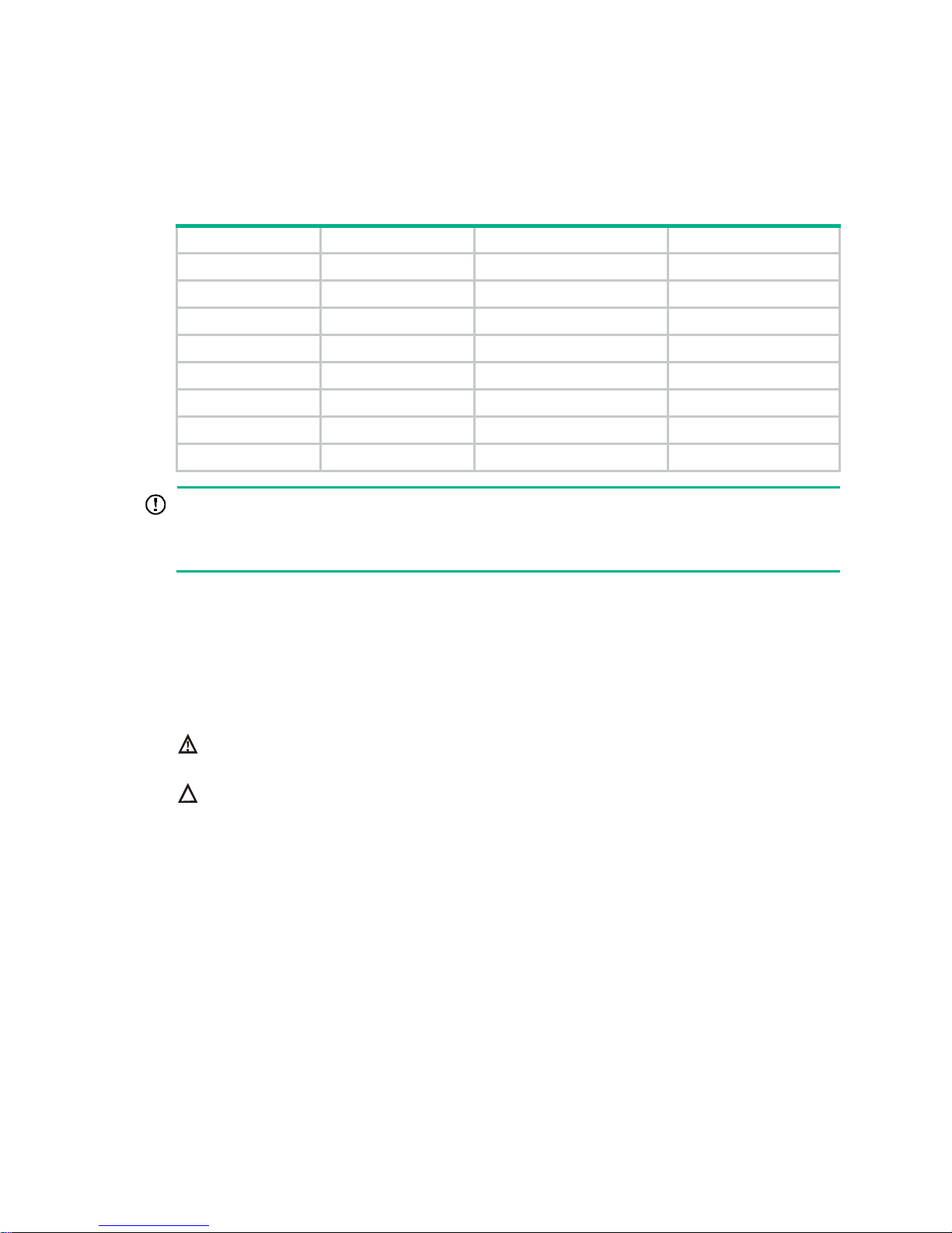
Table 2 Temperature and humidity requirements
Temperature Humidity
0°C to 45°C (32°F to 113°F) 5% to 90% (noncondensing)
Cleanliness
Dust buildup on the chassis might result in electrostatic adsorption, which causes poor contact of
metal components and contact points, especially when indoor relative humidity is low. In the worst
case, electrostatic adsorption can cause communication failure.
Table 3 Dust concentration limit in the equipment room
Substance Concentration limit (particles/m
3
)
Dust particles
≤ 3 x 10
4
(No visible dust on desk in three days)
NOTE:
Dust particle diameter ≥ 5 µm
Page 8
3
The equipment room must also meet strict limits on salts, acids, and sulfides to eliminate corrosion
and premature aging of components, as shown in Tabl e 4 .
Table 4 Harmful gas
limits in the equipment room
Gas Max. (mg/m
3
)
SO2 0.2
H2S 0.006
NH
3
0.05
Cl
2
0.01
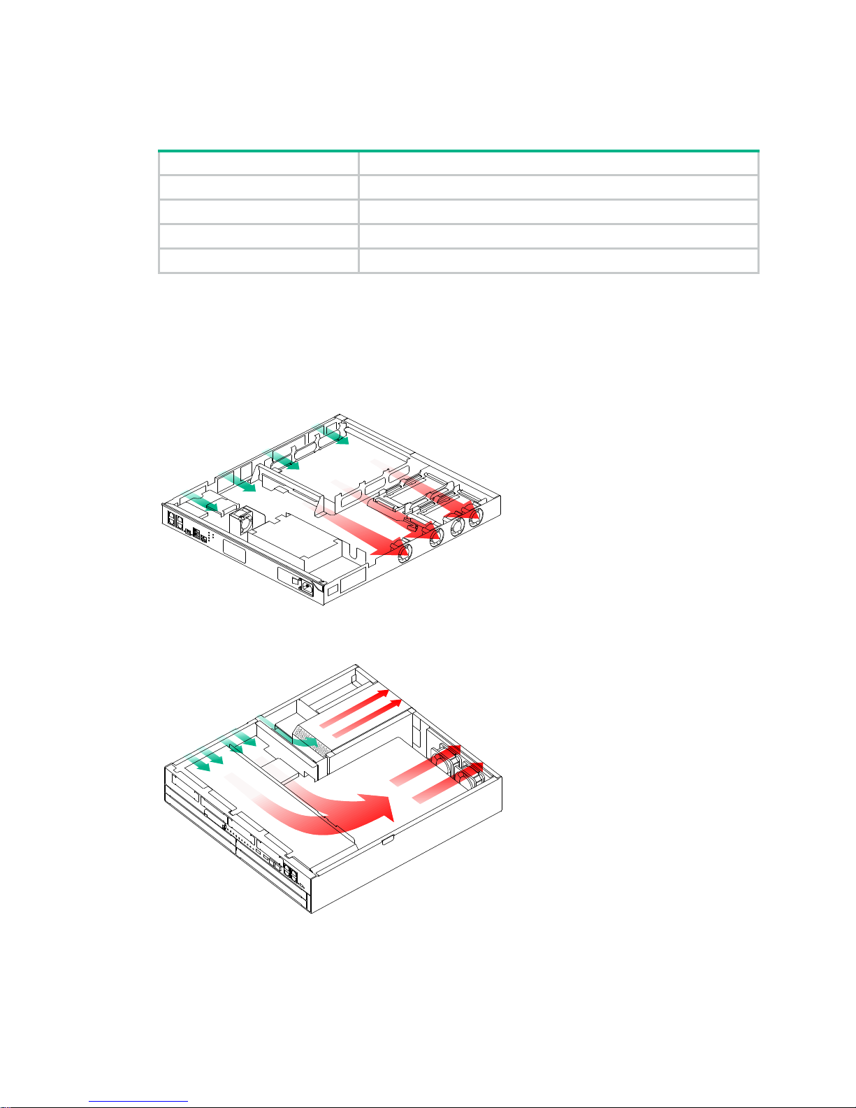
Cooling system
The MSR3012/3024 router uses left to right airflow for heat dissipation, and the MSR3044/3064
router uses left to rear airflow for heat dissipation.
Figure 1 Airflow through the MSR3012/3024 chassis
Figure 2 Airflow through the MSR3044/3064 chassis
To ensure good ventilation, the following requirements must be met:
• The air inlet and outlet vents are not blocked, and leave at least 10 cm (3.94 in) of clearance.
• The installation site has a good cooling system.
Page 9

4
ESD prevention
CAUTION:
Check the resistance of the ESD wrist strap for safety. The resistance reading should be in the range
of 1 to 10 megohm (Mohm) between human body and the ground.
To prevent electrostatic discharge (ESD), follow these guidelines:
• Make sure the router and the floor are well grounded.
• Take dust-proof measures for the equipment room.
• Maintain the humidity and temperature at a proper level.
• Always wear an ESD wrist strap and ESD cloth when touching a circuit board or transceiver
module.
An MSR3000 router does not supply an ESD wrist wrap. Prepare an ESD wrist wrap yourself.
• Place the removed memory module, CF card, or interface module on an antistatic workbench,
with the face upward, or put it into an antistatic bag.
• Touch only the edges, instead of electronic components when you observe or move a removed
memory module, CF card, or interface module.
To attach an ESD wrist strap:
1. Wear the wrist strap on your wrist.
2. Lock the wrist strap tight around your wrist to keep good contact with the skin.
3. Insert the ESD plug into the ESD socket.
4. Make sure the rack is well grounded.
EMI
All electromagnetic interference (EMI) sources, from outside or inside of the switch and application
system, adversely affect the switch in the following ways:
• A conduction pattern of capacitance coupling.
• Inductance coupling.
• Electromagnetic wave radiation.
• Common impedance (including the grounding system) coupling.
To prevent EMI, use the following guidelines:
• If AC power is used, use a single-phase three-wire power receptacle with protection earth (PE)
to filter interference from the power grid.
• Keep the switch far away from radio transmitting stations, radar stations, and high-frequency
devices.
• Use electromagnetic shielding, for example, shielded interface cables, when necessary.
Lightning protection
To better protect the router from lightning, do as follows:
• Make sure the grounding cable of the chassis is well grounded.
• Make sure the grounding terminal of the AC power receptacle is well grounded.
• Install a lightning arrester at the input end of the power supply to enhance the lightning
protection capability of the power supply.
Page 10
5
• Install a special lightning arrester at the input end of outdoor signal lines (for example, E1/T1
line) to which interface modules of the router are connected to enhance the lightning protection
capability.
Rack-mounting
Before mounting the router to a rack, adhere to the following requirements:
• The rack is equipped with a good ventilation system.
• The rack is sturdy enough to support the router and its accessories.
• For heat dissipation and device maintenance, make sure the front and rear of the rack are at
least 0.8 m (2.62 ft) away from walls or other devices, and the headroom in the equipment room
is no less than 3 m (9.84 ft).
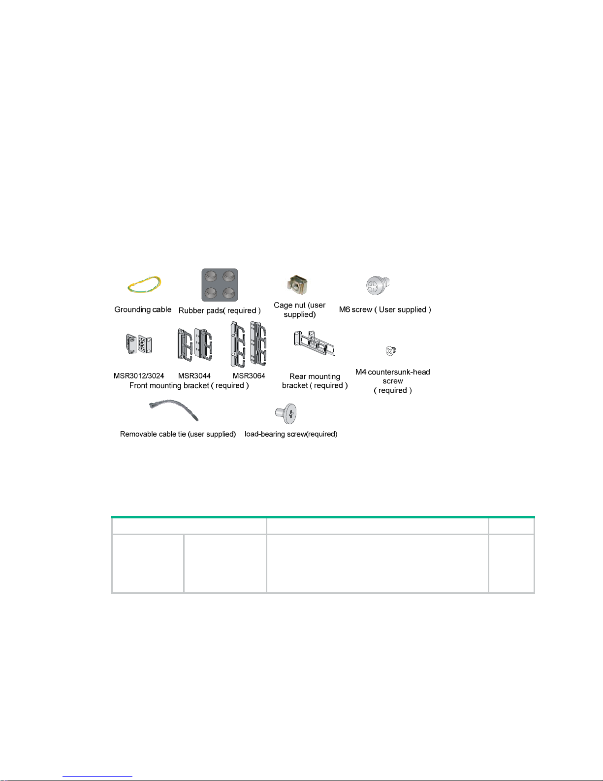
Installation accessories
Checklist before installation
Table 5 Checklist before installation
Item Requirements Result
Installation site Ventilation
• There is a minimum clearance of 10 cm (3.94 in)
around the inlet and outlet vents for heat
dissipation of the router chassis.
• A good ventilation system is available at the
installation site.
Page 11

6
Item Requirements Result
Temperature 0°C to 45°C (32°F to 113°F).
Relative humidity 5% to 90% (noncondensing).
Cleanness
• Dust concentration ≤ 3 × 10⁴ particles/m3.
• No visible dust on desk within three days.
ESD prevention
• The equipment and floor are reliably grounded.
• The equipment room is dust-proof.
• The humidity and temperature are at a proper
level, respectively.
• Wear an ESD wrist strap and uniform when
touching a circuit board.
• Place the removed memory module, CF card, or
interface module on an antistatic workbench, with
the face upward, or put it into an antistatic bag.
• Touch only the edges, instead of electronic
components when observing or moving a removed
memory module, CF card, or interface module.
EMI prevention
• Take effective measures to protect the power
system from the power grid system.
• Separate the protection ground of the router from
the grounding device or lightning protection
grounding device as far as possible.
• Keep the router far away from radio stations, radar
and high-frequency devices working in high
current.
• Use electromagnetic shielding when necessary.
Lightning
protection
• The grounding cable of the chassis is well
grounded.
• The grounding terminal of the AC power
receptacle is well grounded.
• A port lightning arrester is installed. (Optional.)
• A power lightning arrester is installed. (Optional.)
• A signal lightning arrester is installed at the input
end of an external signal cable. (Optional.)
Electricity safety
• Equip an uninterrupted power supply (UPS).
• In case of emergency during operation, switch off
the external power switch.
Workbench
• The workbench is stable enough.
• The workbench is well grounded.
Rack-mounting
requirements
• The rack is equipped with a good ventilation
system.
• The rack is sturdy enough to support the weight of
the router and installation accessories.
• The size of the rack is appropriate for the router.
• The front and rear of the rack are at least 0.8 m
(2.62 ft) away from walls or other devices.
Safety
precautions
• The router is far away from any moist area and heat source.
• The emergency power switch in the equipment room is located.
Tools
• Installation accessories supplied with the router.
• User supplied tools.
Reference
• Documents shipped with the router.
• Online documents.
Page 12

7
Installing the router
WARNING!
To avoid injury, do not touch bare wires, terminals, or parts with high-voltage hazard signs.
IMPORTANT:
• The barcode on the router chassis contains product information that must be provided to local
sales agent before you return a faulty router for service.
• Keep the tamper-proof seal on a mounting screw on the chassis cover intact, and if you want to
open the chassis, contact Hewlett Packard Enterprise for permission. Otherwise, Hewlett
Packard Enterprise shall not be liable for any consequence.
Installation prerequisites
• You have read "Preparing for installation" carefully.
• All requirements in "Preparing for installation" are met.
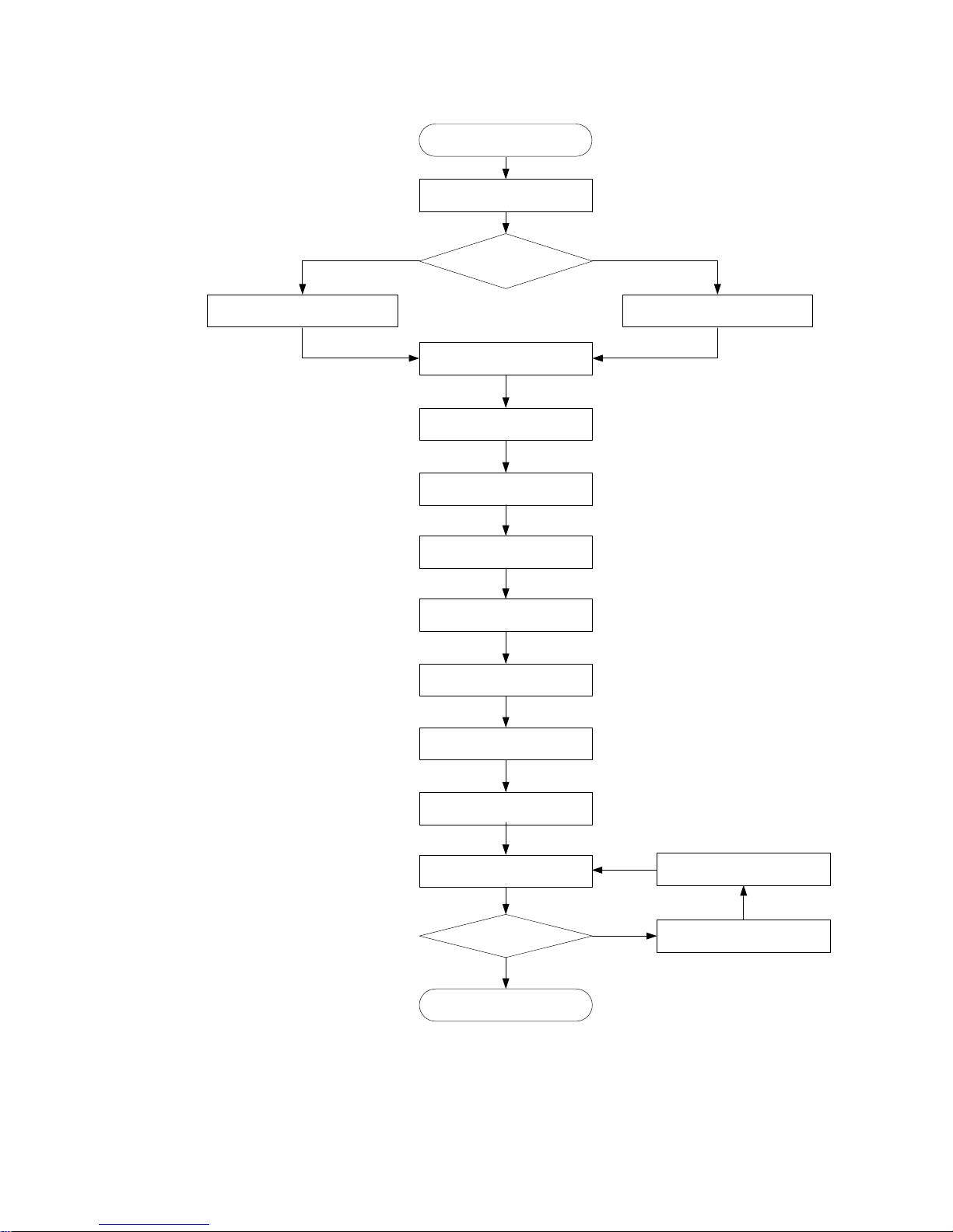
Installation flowchart
You can install the router on a workbench or in a rack. Select an installation method according to the
installation environment, and follow the installation flowchart shown in Figure 3.
Page 13
8
Figure 3 Installation flowchart
Yes
No
Sta r t
Mount the router to a rack
Gr ound the router
Install an interface module
Connect interface ca bles
Install a CF card
Connect the pow er co rd
Verify the installation
Power on the router
Troubleshoot the router
Power off the routerOperating correctly?
En d
Mount to a speci fic
position?
Mount the router to a workbench
Mount the router to a rack
Ex ami ne the w orkbench
Install an air filter
Connect the ro uter to a
terminal
Install a power supply
Page 14
9
Installing the router
Installing an air filter
No air filter is provided with the router. Purchase one yourself. Only the MSR3044 and MSR3064
support air filters.
To install an air filter:
1. Face the left side (side of the inlet vents) of the router.
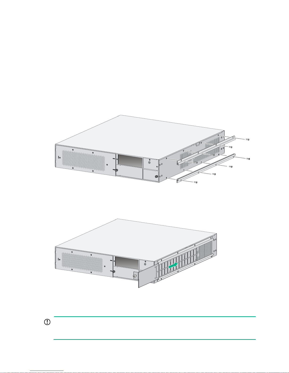
2. Install the upper and lower guide rails of the air filter to the chassis. See Figure 4.
3. Fasten the fastening screws on the guide rails with a Phillips screwdriver.
Figure 4
Installing the upper and lower guide rails
4. Push the air filter along the slide rails from the rear side of the chassis to the front.
5. Fasten the captive screws on the air filter.
Figure 5 Pushing the air filter along the guide rails
Mounting the router on a workbench
IMPORTANT:
• Ensure good ventilation and 10 cm (3.94 in) of clearance around the chassis for heat dissipation.
• Avoid placing heavy objects on the router.
Page 15

10
To mount the router on a workbench:
1. Make sure the workbench is clean, stable, and reliably grounded.
2. Place the router upside down on the workbench and attach the rubber feet to the four round
holes in the chassis bottom.
Figure 6 Attaching the rubber feet
3. Place the router on the workbench with the upside up.
Figure 7 Mounting the router on a workbench
Installing the router in a rack
Mounting brackets
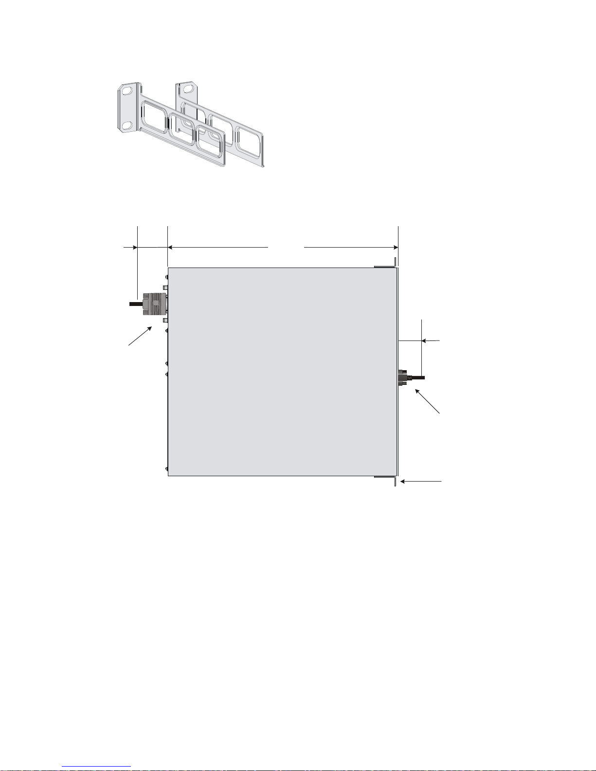
The MSR3000 routers require different types of front mounting brackets, as shown in Figure 8.
Figure 8 Front mounting brackets
Page 16
11
Figure 9 Rear mounting brackets
Rack-mounting clearance requirements
Figure 10 Rack-mounting clearances for the MSR3012/3024
483mm
60mm
Front mounting
bracket
RPS power cord
E1 cable
65mm
Page 17
12
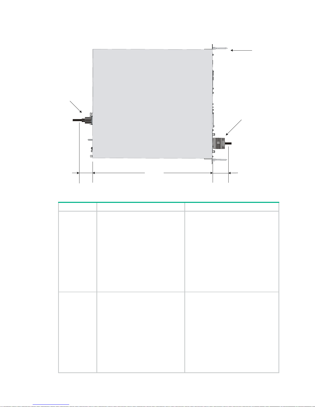
Figure 11 Rack-mounting clearances for the MSR3044/3064
Table 6 Rack-mounting clearance requirements
Model Router dimensions Rack clearance requirements
3012/3024
• Width—440 mm (17.32 in)
• Height—44.2 mm (1.74 in) (1 RU)
• Total depth—608 mm (23.94 in)
{ 483 mm (19.02 in) for the
chassis
{ 65 mm (2.56 in) for connecting
an RPS power cord at the front
of the chassis
{ 60 mm (2.36 in) for connecting
an E1 cable at the rear of the
chassis
The rack must meet all the following
requirements:
• A minimum of 80 mm (3.15 in) between
the front rack post and the front door.
• A minimum of 550 mm (21.65 in)
between the front rack post and the rear
door.
• 290 mm (11.42 in) to 430 mm (16.93 in)
between the front and rear rack posts,
with a clearance of 160 mm (6.30 in)
between the rear rack post and the rear
door, or 450 mm (17.72 in) to 610 mm
(24.02 in) between the front and rear
rack posts.
3044
• Width—440 mm (17.32 in)
• Height—88.2 mm (3.47 in) (2 RU)
• Total depth—600 mm (23.62 in)
{ 480 mm (18.90 in) for the
chassis
{ 60 mm (2.36 in) for connecting
an RPS power cord at the front
of the chassis
{ 60 mm (2.36 in) for connecting
an E1 cable at the rear of the
chassis
The rack must meet all the following
requirements:
• A minimum of 80 mm (3.15 in) between
the front rack post and the front door.
• A minimum of 550 mm (21.65 in)
between the front rack post and the rear
door.
• 310 mm (12.20 in) to 440 mm (17.32 in)
between the front and rear rack posts,
with a clearance of 160 mm (6.30 in)
between the rear rack post and the rear
door, or 465 mm (18.31 in) to 595 mm
(23.43 in) between the front and rear
rack posts.
480mm
E1 cable
60mm
Front mounti ng
bracket
Power cord
60mm
Page 18
13
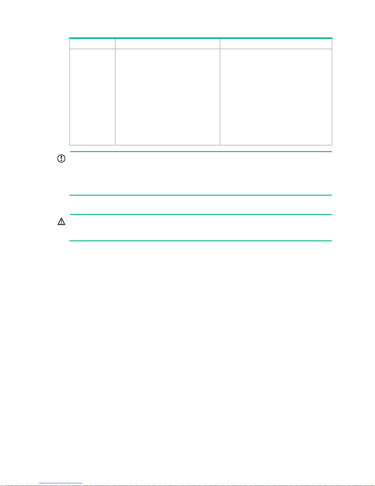
Model Router dimensions Rack clearance requirements
3064
• Width—440 mm (17.32 in)
• Height—130.5 mm (5.14 in) (3 RU)
• Total depth—600 mm (23.62 in)
{ 480 mm (18.90 in) for the
chassis
{ 60 mm (2.36 in) for connecting
an RPS power cord at the front
of the chassis
{ 60 mm (2.36 in) for connecting
an E1 cable at the rear of the
chassis
The rack must meet all the following
requirements:
• A minimum of 80 mm (3.15 in) between
the front rack post and the front door.
• A minimum of 550 mm (21.65 in)
between the front rack post and the rear
door.
• 310 mm (12.20 in) to 440 mm (17.32 in)
between the front and rear rack posts,
with a clearance of 160 mm (6.30 in)
between the rear rack post and the rear
door, or 465 mm (18.31 in) to 595 mm
(23.43 in) between the front and rear
rack posts.
IMPORTANT:
• For the MSR3012/3024 router, use a rack with a depth of more than 0.68 m (2.23 ft) as a best
practice.
• For the MSR3044/3064 router, use a rack shelf and a rack with a depth of more than 0.68 m (2.23
ft) as a best practice.
Mounting the router in the rack
WARNING!
The mounting brackets can only support the weight of the router. To avoid damage to the router, do
not place any objects on the router.
To mount the router in a rack:
1. Use a front mounting bracket to mark the positions of cage nuts, making sure they are at the
same level.
2. Use a rear mounting bracket to mark the positions of cage nuts, making sure the front and rear
mounting brackets are at the same level.
Page 19
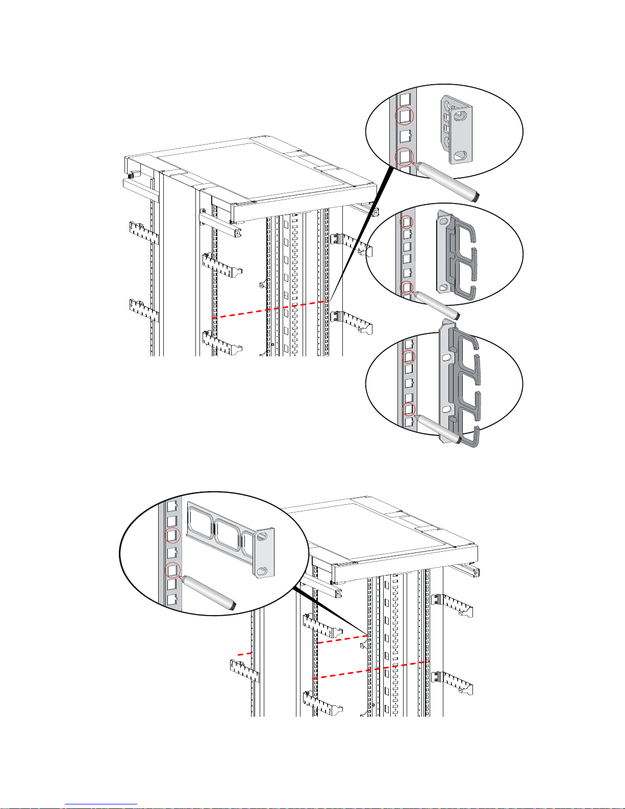
14
Figure 12 Marking the positions of cage nuts for the front mounting brackets
Figure 13 Marking the positions of cage nuts for the rear mounting brackets
Page 20
15
3. Insert one edge of a cage nut into the hole. Use a flat-blade screwdriver to compress the other
edge of the cage nut, and then push the cage nut fully into the hole.
4. Repeat step 3 to install other cage nuts to all the marked positions on the rack posts.
Figure 14 Installing a cage nut
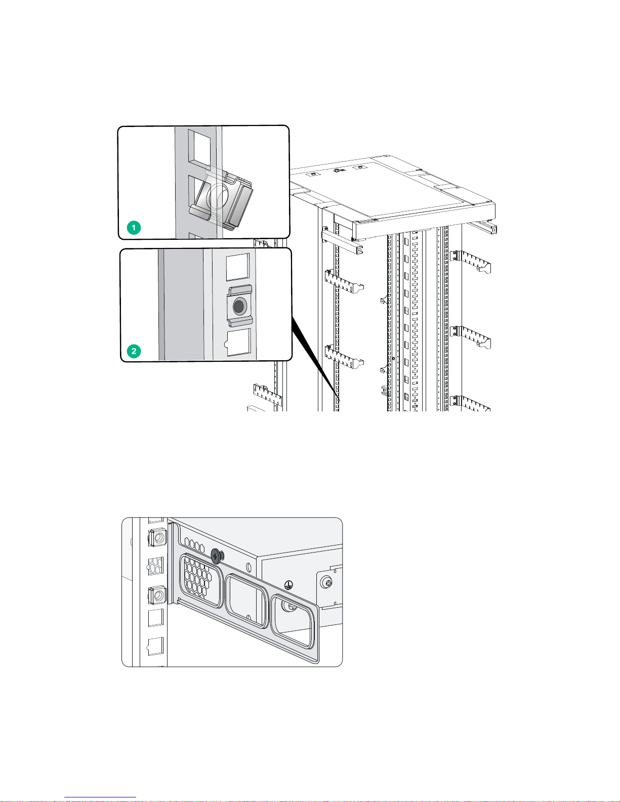
5. Attach the rear mounting brackets to the rack and fasten the screws.
The depth of the router might be greater or smaller than the depth of the rack, depending on the
rack model. If the depth of the router is greater than the depth of the rack, follow Figure 15 to
attach the rear mountin
g brackets. If smaller, follow Figure 16 to attach the rear
mounting
brackets.
Figure 15 Attaching the rear mounting brackets (router depth greater than rack depth)
Page 21
16
Figure 16 Attaching the rear mounting brackets (router depth smaller than rack depth)
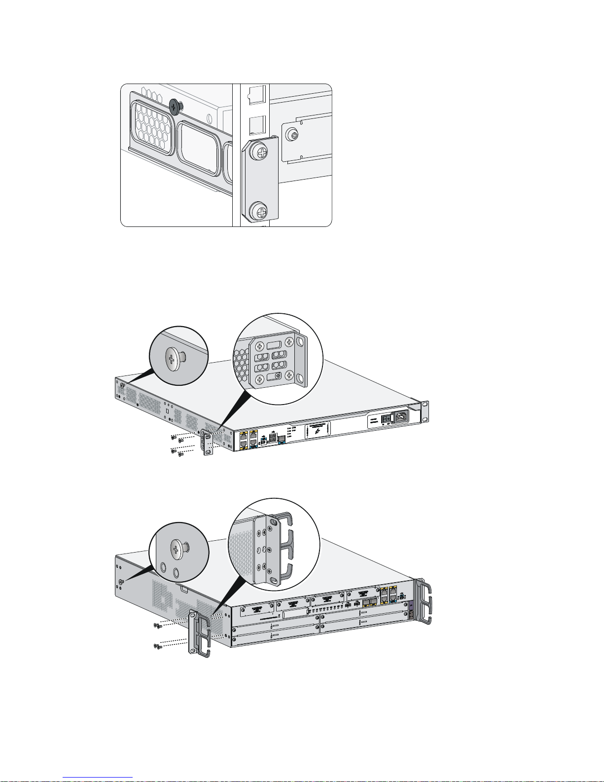
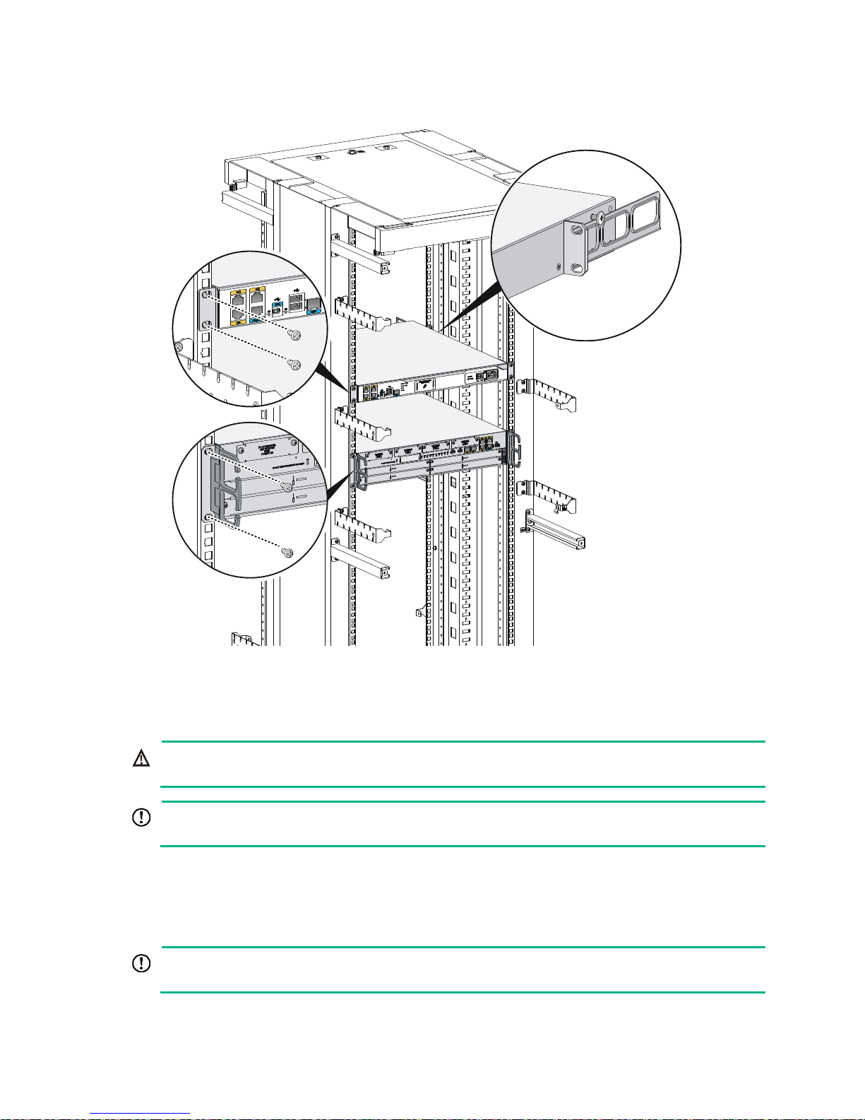
6. Attach the front mounting brackets to the chassis and fasten the screws.
7. Attach load-bearing screws to the rear of the chassis.
Figure 17 Attaching the front mounting brackets and load-bearing screws to the
MSR3012/3024
Figure 18 Attaching the front mounting brackets and load-bearing screws to the MSR3044
Page 22
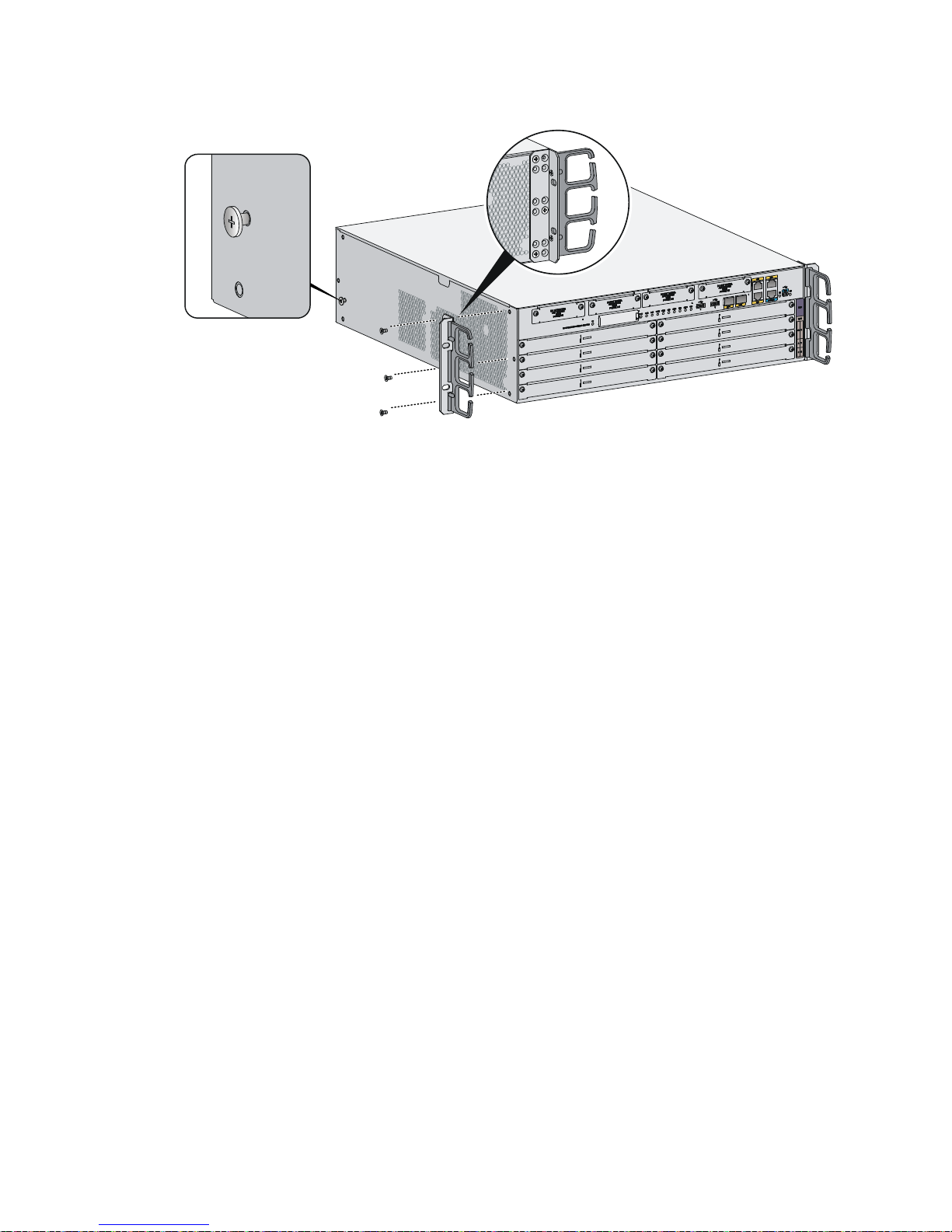
17
Figure 19 Attaching the front mounting brackets and load-bearing screws to the MSR3064
8. Place the router on the rack, making sure the load-bearing screws hang on the rear mounting
brackets. Secure the chassis in the rack by attaching the front mounting brackets with proper
pan head screws onto the back.
Page 23
18
Figure 20 Mounting the router in the rack
Grounding the router
WARNING!
Correctly connecting the router grounding cable is crucial to lightning protection and EMI protection.
IMPORTANT:
The resistance reading should be smaller than 5 ohms between the chassis and the ground.
Grounding the router through the grounding terminal on the
rack
IMPORTANT:
Make sure the rack is reliably grounded before grounding the router.
To connect the grounding cable:
Page 24
19
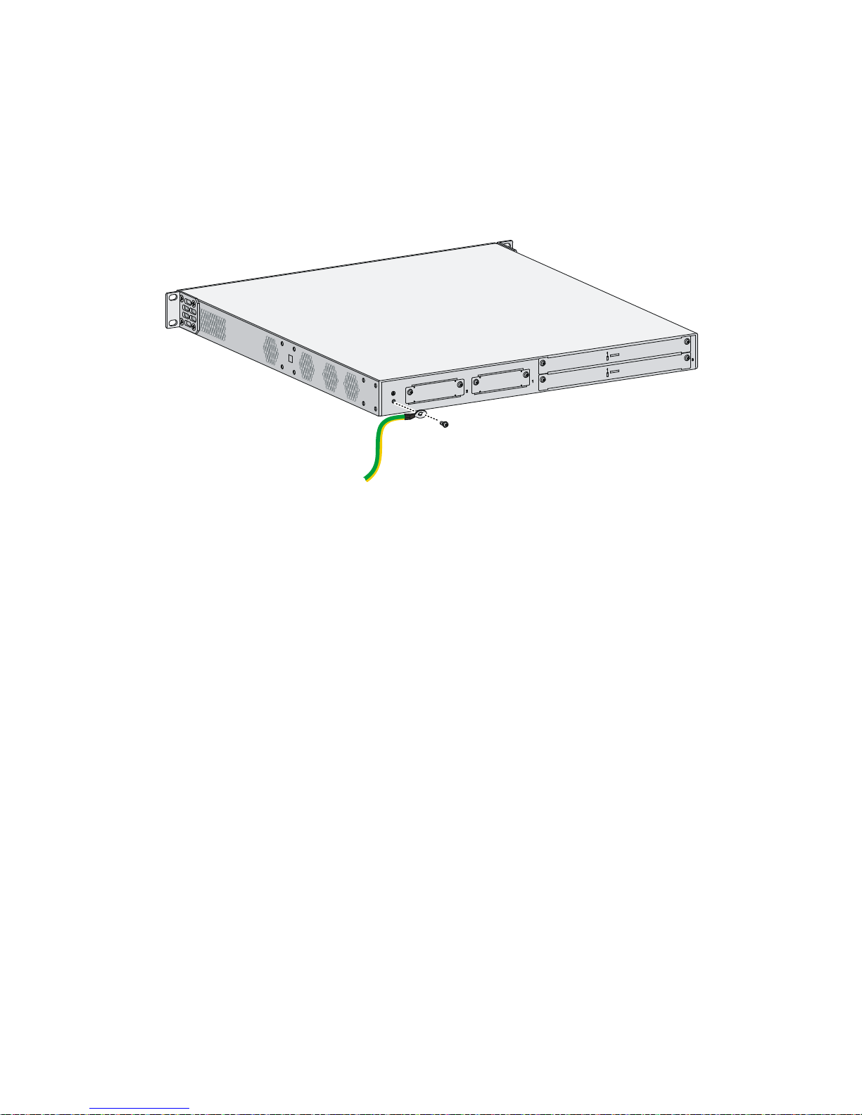
1. Remove the two grounding screws from the rear panel of the chassis.
2. Attach the grounding screw to the ring terminal of the grounding cable. See Figure 21.
3. Use a Phillips screwdriver to fasten the gr
ounding screw into the grounding screw hole.
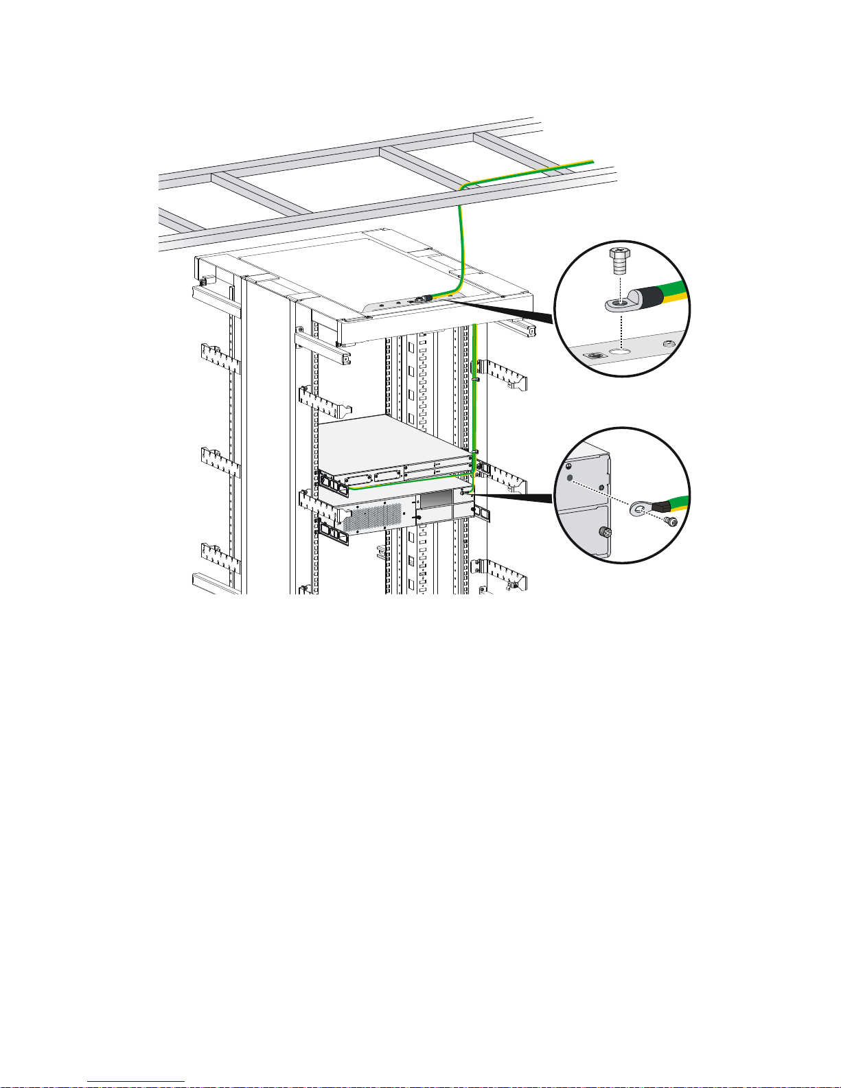
4. Remove the grounding screw from the grounding point on the rack.
5. Use a needle-nose pliers to bend a hook at the other end of the grounding cable, attach it to the
grounding point, and secure it with a screw. See Figure 22.
Figure 21
Conn
ecting the grounding cable to the grounding hole of the router
Page 25
20
Figure 22 Grounding the router through the grounding terminal on the rack
Page 26
21
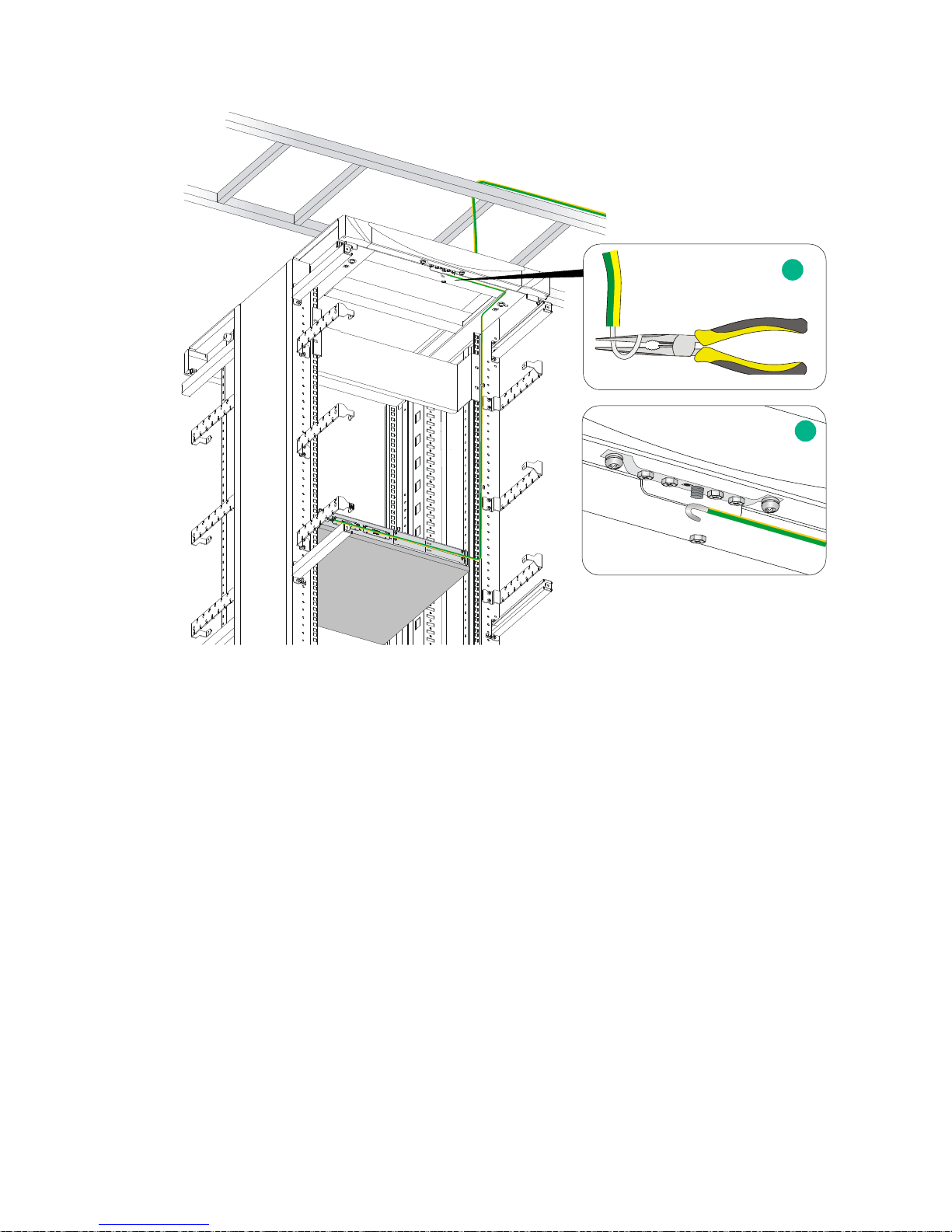
Grounding the router with a grounding strip
If a grounding strip is available at the installation site, connect the grounding cable to the grounding
strip.
Follow the same procedures in "Grounding the router through the grounding terminal on the rack" to
conne
ct the grounding cable.
1
2
Page 27

22
Figure 23 Grounding the router with a grounding strip
Grounding the router with a grounding conductor buried in
the earth ground
If the installation site has no grounding strips, but earth ground is available, hammer a 0.5 m (1.64 ft)
or longer angle iron or steel tube into the earth ground to serve as a grounding conductor. The steel
tube must be zinc-coated. Weld the yellow-green grounding cable to the angel iron or steel tube and
treat the joint for corrosion protection.
Installing an interface module
Installing a SIC
CAUTION:
SIC interface modules are not hot swappable. Make sure the router is powered off before installing a
SIC.
To install a SIC:
1. Remove the fastening screws with a Phillips screwdriver to remove the filler panel.
Keep the removed filler panel for future use.
2. Push the SIC slowly along the slide rails into the slot until it makes close contact with the
backplane of the router.
3. Use a Phillips screwdriver to fasten the captive screws on the SIC.
1 2
Page 28

23
Figure 24 Removing the filler panel
Figure 25 Installing the SIC
Installing a DSIC
CAUTION:
DSIC interface modules are not hot swappable. Make sure the router is powered off before installing
a DSIC.
To install a DSIC:
1. Remove the screws on the filler panel on a SIC slot of an MSR3024, MSR3044, or MSR3064 to
remove the filler panel.
For an MSR3024, MSR3044, or MSR3064, a DSIC can be installed after you remove the slot
divider between slot 1 and slot 2, or between slot 3 and slot 4.
2. Loosen the captive screws on the slot divider and pull out the slot divider.
You can install a DSIC to an MSR3024, MSR3044, or MSR3064 after you remove the slot
divider.
Page 29

24
Figure 26 Removing the filler panel
Figure 27 Removing the slot divider
3. Insert the DSIC into the slot and push it along the slide rails until it makes close contact with the
backplane of the router.
Figure 28 Installing a DSIC
4. Fasten the captive screws to secure the DSIC.
Page 30

25
Installing an HMIM
IMPORTANT:
• You can install an HMIM when the router is powered on. However, before replacing an HMIM
when the router is powered on, you must execute the remove hmimslot slotnumber command.
• An HMIM interface module can be 1U or 0.5U. This section takes a 0.5U interface module for
example. When you install a 1U interface module to an MSR router, remove the filler panels of
the target slot and the neighboring slot above.
• If you install HMIMs on both of the HMIM slots on an MSR3024, when you insert an HMIM to the
upper slot, slightly press down the HMIM, and then push it into the slot.
To install an HMIM:
1. Remove the fastening screws with a Phillips screwdriver to remove the filler panel.
Keep the removed filler panel for future use.
2. Push the HMIM slowly along the slide rails into the slot until it makes close contact with the
backplane of the router.
Figure 29 Removing the filler panel
Figure 30 Installing an HMIM
3. Fasten the captive screws on the HMIM to secure it to the router.
Page 31

26
Installing a MIM
IMPORTANT:
• To install a MIM, install it to the HMIM adapter and then insert it into the HMIM slot.
• You can install a MIM when the router is powered on. However, before replacing a MIM when the
router is powered on, you must execute the remove hmimslot slotnumber command.
• A MIM interface module can be 1U or 0.5U. This section takes a 0.5U interface module for
example. When you install a 1U interface module to an MSR router, remove the filler panels of
the target slot and the neighboring slot above, and use the 1U HMIM adapter.
• If you install MIMs on both of the HMIM slots on an MSR3024, when you insert a MIM to the
upper slot, slightly press down the MIM, and then push it into the slot.
To install a MIM:
1. Remove the fastening screws with a Phillips screwdriver to remove the filler panel.
2. Push the MIM slowly along the slide rails until it makes close contact with the backplane of the
HMIM adapter.
3. Fasten the fastening screws.
4. Fasten the captive screws on the MIM to secure it to the HMIM adapter.
Figure 31 Attaching a MIM to an HMIM adapter
5. Push the MIM into the slot along the slide rails until it makes close contact with the backplane of
the router.
6. Fasten the captive screws to secure the MIM to the router.
Figure 32 Installing the MIM to the router
Page 32

27
Connecting the router to the network
Connect the router to the network before powering on the router. This section describes how to
connect the router to the network through Ethernet cables.
Connecting an Ethernet cable
1. Plug one end of an Ethernet twisted pair cable into the copper Ethernet port (RJ-45 port) to be
connected on the router.
2. Plug the other end of the cable into the RJ-45 port of the peer device.
Figure 33 Connecting the router to a PC
Connecting an optical fiber
WARNING!
Do not stare into any fiber port when you connect an optical fiber. The laser light emitted from the
optical fiber may hurt your eyes.
Follow these guidelines when you connect a fiber cable:
• Never bend or curve a fiber when connecting it.
• Make sure the Tx and Rx ends are properly connected.
• Keep the fiber end clean.
• Be sure to install the dust cover if the fiber port is not connected to a fiber connector.
To connect an optical fiber:
1. Remove the dust plug from a fiber port of the router.
2. Remove the dust cover from the transceiver module, and plug the end without a pull latch into
the fiber port.
3. Remove the dust cover from the fiber connector.
4. Identify the Rx and Tx ports. Plug the LC connector at one end of one fiber cable into the Rx port
of the router and the LC connector at the other end into the Tx port of the peer device. Plug the
LC connector at one end of another fiber cable into the Tx port of the router and the LC
connector at the other end to the Rx port of the peer device.
Page 33

28
5. Examine the Ethernet port LED after connection. For more information, see "Appendix B
LEDs."
Figure 34 Connecting an optical fiber
Installing a CF card
1. Open the CF card cover by pressing the spring clip.
2. Push the CF card eject button all the way into the slot, and make sure the button does not
project from the panel.
3. Insert the CF card into the slot following the direction shown in Figure 35, and make sure it does
not proje
ct from the slot.
4. Close the CF card cover.
Figure 35 Installing a CF card
Page 34

29
Logging in through the console port
Connecting a console cable
You can log in only through the console port by using a console or USB console cable the first time
you log in to your router.
IMPORTANT:
When you connect a PC to a powered-on router, connect the RJ-45 connector to the router after
connecting the DB-9 connector of the console cable to the PC.
To connect a console cable:
1. Plug the DB-9 female connector to the serial port of the configuration terminal.
2. Connect the RJ-45 connector to the console port of the router.
NOTE:
If the configuration terminal does not have an RS-232 serial port, a serial adapter is required to
connect the console cable to a USB port on the terminal.
Figure 36 Connecting the console cable
IMPORTANT:
Download and install the USB console driver program before configuring the device when you
connect the device through a USB console cable.
To connect a USB cable:
1. Connect the USB port to the PC.
2. Connect the other end to the USB console port of the router.
Page 35

30
Figure 37 Connecting the USB cable
3. Click the following link, or copy it to the address bar on the browser to log in to download page
of the USB console driver, and download the driver.
http://www.exar.com/connectivity/uart-and-bridgi
ng-solutions/usb-uarts/xr21v1410
4. Select a driver program according to the operating system you use:
{ XR21V1410_XR21B1411_Windows_Ver1840_x86_Installer.EXE—Applicable to 32-bit
operating systems.
{ XR21V1410_XR21B1411_Windows_Ver1840_x64_Installer.EXE—Applicable to 64-bit
operating systems.
5. Click Next on the installation wizard.
Figure 38 Device driver installation wizard
6. Click Continue Anyway if the following dialog box appears.
Page 36

31
Figure 39 Software installation
7. Click Finish.
Figure 40 Completing the device driver installation wizard
Setting terminal parameters
To access the device through the console port, you must run a terminal emulator program
(HyperTerminal, PuTTY, or Tera Term) on the configuration terminal. For information about using a
terminal emulator program, see the program's user guide.
Page 37

32
The following are the required terminal settings:
• Baud rate—9600.
• Data bits—8.
• Stop bits—1.
• Parity—none.
• Flow control—none.
Installing a power supply
IMPORTANT:
• Only the MSR3044 and MSR3064 support power supplies.
• To install multiple power supplies, make sure all power supplies are AC input or DC input.
Installing an AC/DC power supply
1. Face the front of the router and locate the slot to be used.
2. Loosen the captive screws with a Phillips screwdriver to remove the filler panel from the slot.
Keep the removed filler panel for future use.
Skip this step if the router is shipped with this slot empty.
3. Holding the handle of the power supply with one hand and supporting the bottom of the power
supply with the other hand, insert the power supply slowly along the slide rails until it makes
close contact with the backplane.
4. Use a Phillips screwdriver to fasten the captive screws on the two sides of the power supply.
Figure 41 Installing an AC power supply
Page 38

33
Figure 42 Installing a DC power supply
Installing a PoE power supply
1. Face the front of the router and locate the slot to be used.
2. Loosen the captive screws with a Phillips screwdriver to remove the filler panel from the slot.
Keep the removed filler panel for future use.
Skip this step if you install the power supply to the PWR1 slot.
3. Holding the handle of the power supply with one hand and supporting the bottom of the power
supply with the other hand, insert the power supply slowly along the slide rails until it makes
close contact with the backplane.
4. Use a Phillips screwdriver to fasten the captive screws on the two sides of the power supply.
Figure 43 Installing a PoE power supply
Connecting the power cord
The power cords in the figures of this section are only for illustration.
Connecting an AC power cord
1. Make sure the router is well grounded, and the power switch on the router is in the OFF
position.
2. Connect one end of the AC power cord to the AC receptacle on the router, and use a cable tie to
secure the power cord.
3. Connect the other end of the power cord to the AC power source.
Page 39

34
Figure 44 Connecting an AC power cord to an MSR3012/3024 router
Figure 45 Connecting an AC power cord to an MSR3044/3064 router
Connecting a DC power cord
CAUTION:
The power cord color code scheme in this section is for illustration only. The cable delivered for you
r
country or region might use a different color scheme. When you connect a power cord, always
identify the polarity symbol on its wires.
The MSR3012/3024 and MSR3044/3064 use different DC connectors, but the power cord
connection procedures are the same.
To connect DC power cords:
1. Make sure the router is well grounded, and the power switch on the router is in the OFF
position.
Page 40

35
2. Loosen the captive screws on the power supply with a Phillips screwdriver to remove the power
supply connector.
3. Connect one end of the DC power cord supplied with the router to the DC receptacle on the
router.
4. Connect the other ends of the wires to the DC power source wiring terminals, with the negative
wire (– or L–) to the negative terminal (–) and the positive wire (+ or M/N) to the positive terminal
(+).
Figure 46 Connecting a DC power cord for an MSR3012/3024
Figure 47 Connecting a DC power cord for an MSR3044/3064
Connecting an RPS power cord
The MSR3012 and MSR3024 offer remote power supply (RPS) support. As an external power supply,
RPS can provide power supply for the device in case of power supply abnormality. It enhances the
reliability of the device.
The router has a sticky label and a protective cover when shipped to protect the RPS receptacle.
To connect an RPS power cord:
1. Remove the sticky label.
1
2
1
2
Page 41

36
2. Remove the screws on the protective cover with a screw driver to remove the protective cover,
as shown in the following figure:
Figure 48 Removing the sticky label and protective cover
3. Insert one end of the RPS power cord to the RPS receptacle on the router and fasten the
screws on the RPS power cord plug.
4. Make sure the RPS power is OFF and connect the other end of the power cord to the RPS
power source.
Figure 49 Connecting the RPS power cord
Verifying the installation
After you complete the installation, verify the following information:
• There is enough space for heat dissipation around the router, and the rack or workbench is
stable.
• USB devices and interface modules are properly installed.
• The router, rack, and power cords are reliably grounded.
• The correct power source is used.
Powering on the router
Verifying before power-on
Before powering on the router, verify the following items:
• The power supplies are correctly installed.
• The power cord and grounding cable are properly connected.
Page 42

37
• The power source voltage meets the requirement of the router.
• The console cable is properly connected, the terminal or PC used for configuration has started,
and the configuration parameters have been set.
• If a CF card is used, verify that the CF card is in position.
• Make sure the installed HMIMs/MIMs are in position.
Powering on the router
1. Turn on the switch of the power supply system for the router.
2. Turn on the switch of the AC or DC power supplies.
Displaying boot information
Power on the router, and you can see the following information:
System is starting...
Press Ctrl+D to access BASIC-BOOTWARE MENU...
Booting Normal Extended BootWare........
The Extended BootWare is self-decompressing....Done.
****************************************************************************
* *
* HPE MSR3064 BootWare, Version 1.60 *
* *
****************************************************************************
Copyright (c) 2010-2015 Hewlett Packard Enterprise Development LP
Compiled Date : Dec 17 2015
CPU ID : 0x4
Memory Type : DDR3 SDRAM
Memory Size : 2048MB
BootWare Size : 1024KB
Flash Size : 8MB
cfa0 Size : 247MB
CPLD Version : 2.0
PCB Version : 2.0
BootWare Validating...
Press Ctrl+B to access EXTENDED-BOOTWARE MENU...
Loading the main image files...
Loading file cfa0:/msr3000-cmw710-system-e000603.bin........................
...............................Done.
Loading file cfa0:/msr3000-cmw710-security-e000603.bin.........Done.
Loading file cfa0:/msr3000-cmw710-voice-e000603.bin...........Done.
Loading file cfa0:/msr3000-cmw710-data-e000603.bin............Done.
Loading file cfa0:/msr3000-cmw710-boot-e000603.bin.......................
Done.
Page 43

38
Image file cfa0:/msr3000-cmw710-boot-e000603.bin is self-decompressing......
..........Done.
System image is starting...
Line aux0 is available.
Press ENTER to get started.
Press Enter, and the following prompt appears:
<HPE>
You can now configure the router.
NOTE:
To access the CLI when the device boots with empty configuration, press Ctrl+D.
Examining the router after power-on
After the router is powered on, verify that:
• The LEDs on the front panel are operating correctly:
LED Status Description
PWR Steady green The power supply is supplying power correctly.
SYS Slow flashing green The router is operating correctly.
• The configuration terminal displays information properly. For local configuration, the
configuration terminal displays the boot information (see "Displaying boot information").
• If you press Enter a
s prompted after system bootup, the router is ready to configure.
Configuring basic settings for the router
After the router is powered on for the first time, configure the basic settings for the router. For more
information, see HPE MSR Routers Fundamentals Configuration Guide (V7) and HPE MSR Routers
Fundamentals Command Reference (V7).
Page 44

39
Replacement procedure
IMPORTANT:
• The barcode on the router chassis contains product information that must be provided to local
sales agent before you return a faulty router for service.
• Keep the tamper-proof seal on a mounting screw on the chassis cover intact, and if you want to
open the chassis, contact Hewlett Packard Enterprise for permission. Otherwise, Hewlett
Packard Enterprise shall not be liable for any consequence.
Replacing a power supply
Power supplies are hot swappable.
The replacement procedure of an AC power supply is the same as a DC power supply. This section
uses an AC power supply as an example.
To replace a power supply:
1. Locate the power supply to be removed and use a Phillips screwdriver to completely loosen the
captive screws on the power supply.
2. Holding the handle of the power supply with one hand and supporting the bottom of the power
supply with the other hand, gently pull the power supply out of the slot along the slide rails.
Put the removed power supply on an antistatic workbench or into an antistatic bag.
Figure 50 Pulling a power supply out of the slot
3. Install a new power supply. For the installation procedure, see "Installing the router."
Install a filler panel if you do not install a new power supply.
Page 45

40
Locating internal modules
Removing chassis covers
WARNING!
• To avoid bodily injury and equipment damage, make sure all power supplies connected to the
router are powered off, all power cords and interface cables are removed before you maintain the
hardware.
• Wear an ESD wrist strap and make sure it makes good skin contact and is reliably grounded.
• After you maintain the hardware, reinstall the chassis cover.
Removing the chassis cover from the MSR3012/MSR3024
1. Place the router on a flat ground and have the rear panel face you.
2. Use a Phillips screwdriver to remove the screws on the rear panel and the screws on the left
and right sides of the chassis.
3. Rotate a flat-blade screwdriver to separate the chassis and the cover as shown in Figure 52.
4. Raise the cha
ssis cover until its front edge is separated from the chassis bottom completely.
5. Pull the chassis cover towards you until the tab on the back edge is disengaged from the front
panel, and put away the cover.
Figure 51 Removing chassis cover screws
Figure 52 Rotating the flat-blade screwdriver
Page 46

41
Figure 53 Lifting the chassis cover
Removing the chassis cover from the MSR3044/MSR3064
1. Place the router on a flat ground.
2. Use a Phillips screwdriver to remove the fastening screws at the top of the router from chassis
cover.
3. Lift the chassis cover and put it away.
Figure 54 Removing chassis cover screws
Figure 55 Lifting the chassis cover
Page 47

42
Locating internal modules
Figure 56 MSR3012 internal module locations
(1) Front panel (2) Rear panel (3) VPM
1
3
2
Page 48

43
Figure 57 MSR3024 internal module locations
(1) Front panel (2) Rear panel (3) VPM
(4) Memory module
Page 49

44
Figure 58 MSR3044 internal module locations
(1) Front panel (2) Rear panel (3) VPMs
(4) Memory module
Page 50

45
Figure 59 MSR3064 internal module locations
(1) Front panel (2) Rear panel (3) VPMs
(4) Memory module
Replacing a VPM
VPM (Voice Processing Module) functions to implement the encryption/decryption, EC and CNG of
voices. The following types of VPM modules are available on the MSR3000 routers:
• 256-channel voice processing module (256-VPM)
• 512-channel voice processing module (512-VPM)
Page 51

46
Figure 60 VPM
To replace a VPM:
1. Pull the release latches away from the VPM at both ends so that the VPM springs up from the
slot.
2. Holding the non-conductive edge, remove the VPM.
Keep the removed VPM for future use.
3. Align the polarization notch of a new VPM with the VPM slot on the main board and insert it into
the slot along the slide rails.
4. Carefully and firmly press the VPM at both ends until you hear a click. This indicates the VPM is
seated in the slot.
5. Verify that the release latches have firmly locked the VPM in position.
Figure 61 Removing a VPM
Figure 62 Installing a VPM
Replacing a memory module
An MSR3012 router does not support memory replacement.
To replace a memory module:
1 2
Page 52

47
1. Pull the release latches away from the memory module at both ends so that the memory
module springs up from the slot.
2. Holding the non-conductive edge, remove the memory module.
Keep the removed memory module for future use.
3. Align the polarization notch of a new memory module with the memory module slot on the main
board and insert the memory module into the slot along the slide rails.
4. Carefully and firmly press the memory module at both ends until you hear a click. This indicates
the memory module is seated in the slot.
5. Verify that the release latches have firmly locked the memory module in position.
Figure 63 Removing a memory module
Figure 64 Installing a memory module
Replacing an air filter
1. Use a Phillips screwdriver to completely loosen the captive screws of the air filter.
2. Gently pull the air filter out along the slide rails.
Figure 65 Removing an air filter
Page 53

48
3. Install a new air filter. For the installation procedure, see "Installing the router."
To remove the slide rails, completely loosen the fastening screws of the slide rails.
To install new slide rails, see "Installing the router."
Figure 66 Removing slide rails
Replacing a CF card
CAUTION:
Execute the umount cfb0: command before you remove the CF card if the router is powered on.
To replace a CF card:
1. Press down the spring clip of the CF card cover and open the cover.
2. Press the eject button to eject the CF card part-way out of the CF card reader, and then pull the
CF card out of the CF card reader.
Keep the removed CF card for future use.
Page 54

49
Figure 67 Removing the CF card
3. Install a new CF card. For the installation procedure, see "Installing the router."
If you do not install a new CF card, close the CF card cover.
Replacing a SIC
CAUTION:
SIC interface modules are not hot swappable. Make sure the router is powered off before installing a
SIC.
To replace a SIC:
1. Completely loosen the captive screws of the SIC.
2. Gently pull the SIC out along the slide rails.
3. Install a new SIC. For the installation procedure, see "Installing the router."
If you do not install a SIC, install a filler panel and tighten the screws.
1
2
3
Page 55

50
Figure 68 Pulling a SIC out
Figure 69 Installing a filler panel
Replacing a DSIC
CAUTION:
DSIC interface modules are not hot swappable. Make sure the router is powered off before installing
a DSIC.
To replace a DSIC:
1. Completely loosen the captive screws of the DSIC.
2. Gently pull the DSIC out along the slide rails.
If you need to install SIC or DSIC interface modules, see "Installing the router" for the
installation procedure.
To install filler panels, proceed to steps 3 and 4.
3. Gently push the slot divider into the DSIC slot along the slide rails and tighten the screws.
4. Install filler panels and tighten the screws.
Page 56

51
Figure 70 Removing a DSIC
Figure 71 Installing a slot divider
Figure 72 Installing filler panels
Replacing an HMIM
WARNING!
You can replace an HMIM when the router is powered on. However, before replacing an HMIM when
the router is powered on, you must execute the remove hmimslot slotnumber command.
Page 57

52
To replace an HMIM:
1. Completely loosen the captive screws of the HMIM.
2. Gently pull the HMIM out of the slot along the slide rails.
3. Install a new HMIM. For the installation procedure, see "Installing the router."
If you do not install a new HMIM, install a filler panel and tighten the screws.
Figure 73 Pulling the HMIM out of the slot
Figure 74 Installing a filler panel
Replacing a MIM
WARNING!
You can replace a MIM when the router is powered on. However, before replacing a MIM when the
router is powered on, you must execute the remove hmimslot slotnumber command.
To replace a MIM:
1. Completely loosen the captive screws of the HMIM adapter.
2. Gently pull the MIM and the HMIM adapter out of the slot along the slide rails.
Page 58

53
Figure 75 Removing a MIM and the HMIM adapter
3. Completely loosen the captive screws of the MIM, remove the screws that secure the MIM to
the HMIM adapter, and pull the MIM out of the HMIM adapter along the slide rails.
Keep the removed MIM for future use.
4. Install a new MIM. For the installation procedure, see "Installing the router."
If you do not install a new MIM in the slot, install a filler panel and tighten the screws.
Figure 76 Removing a MIM
Figure 77 Installing a filler panel
Page 59

54
Troubleshooting
IMPORTANT:
• The barcode on the router chassis contains product information that must be provided to local
sales agent before you return a faulty router for service.
• Keep the tamper-proof seal on a mounting screw on the chassis cover intact, and if you want to
open the chassis, contact Hewlett Packard Enterprise for permission. Otherwise, Hewlett
Packard Enterprise shall not be liable for any consequence.
Troubleshooting the power supply system failure
Symptom
The router cannot be powered on. The power LED is off.
Solution
To resolve the problem:
1. Turn off the power switch of the power source.
2. Verify that the power cord of the router is correctly connected to the router and the power
source.
3. Verify that the power source is operating correctly.
4. Verify that the power cord is in good condition.
5. If the problem persists, contact Hewlett Packard Enterprise Support.
Troubleshooting fan failures
Symptom
After the router starts up, the following error message appears on the configuration terminal:
%Jun 22 16:11:37:485 2015 HPE DEV/4/FAN FAILED:
Fan 1 failed.
Solution
To resolve the problem:
1. Verify that the fans are in position.
2. Examine whether any obstacle enters the chassis and blocks the fans.
3. Examine whether any fan stops rotating.
4. Turn off the power switch.
5. If the problem persists, contact Hewlett Packard Enterprise Support.
Troubleshooting the configuration system failures
If the router operates correctly after being powered on, the boot information is displayed on the
configuration terminal. If the configuration system is faulty, the configuration terminal displays
garbled characters or does not display anything.
Page 60

55
No display on the configuration terminal
Symptom
After the router is powered on, the console terminal does not display anything.
Solution
To resolve the problem:
1. Verify that the power supply system is operating correctly.
2. Verify that the console cable is properly connected and the connected serial port is the same as
the port configured on the terminal.
3. Verify that the terminal is configured correctly.
{ Bits per second—9600.
{ Data bits—8.
{ Parity—None.
{ Stop bits—1.
{ Flow control—None.
{ Terminal Emulation—VT100.
4. Verify that the console cable is not broken.
5. If the problem persists, contact Hewlett Packard Enterprise Support.
Garbled characters on the configuration terminal
Symptom
After the router is powered on, the configuration terminal displays garbled characters.
Solution
To resolve the problem:
1. Verify that the Data bits field is set to 8 for the terminal. If the Data bits field is set to 5 or 6, the
terminal displays garbled characters.
2. If the problem persists, contact Hewlett Packard Enterprise Support.
No response from the serial port
Symptom
No boot information is displayed on the configuration terminal when the router starts up or restarts
up.
Solution
To resolve the problem:
1. Verify that the serial cable is in good condition.
2. Verify that the serial port attributes are correct.
3. If the problem persists, contact Hewlett Packard Enterprise Support.
Page 61

56
Troubleshooting user password loss
Symptom
If you lose your user password, you cannot log in to the system.
Solution
To resolve the problem:
1. Select 8 on the main BootWare menu to clear the console interface login password:
===========================<EXTEND-BOOTWARE MENU>===========================
|<1> Boot System |
|<2> Enter Serial SubMenu |
|<3> Enter Ethernet SubMenu |
|<4> File Control |
|<5> Modify BootWare Password |
|<6> Skip Current System Configuration |
|<7> BootWare Operation Menu |
|<8> Skip authentication for console login |
|<9> Storage Device Operation |
|<0> Reboot |
============================================================================
Enter your choice(0-9):8
The following output indicates that you have successfully cleared the console login password.
Clear Application Password Success!
2. Select 0 from the main BootWare menu to reboot the system.
System is rebooting now.
System start booting...
Booting Normal Extend BootWare....
3. After the system restarts up, set a new password.
<Sysname> system-view
[Sysname] user-interface console 0
[Sysname-ui-console0] authentication-mode password
[Sysname-ui-console0] set authentication password cipher 123456
The commands above configure password authentication for the console user interface and set
the ciphertext password 123456.
For security purposes, all keys set with the set authentication password { cipher | simple }
password command, including keys configured in plain text, are saved in cipher text.
4. Execute the save command after modifying the user password to save the new password.
[Sysname] save
NOTE:
As a best practice, save the modification as the default configuration file.
5. If the problem persists, contact Hewlett Packard Enterprise Support.
Page 62

57
Troubleshooting interface module, cable, and
connection failure
Symptom
After an interface module is installed and the router is powered on, the LEDs on the interface module
panel indicate that the interface module is operating improperly.
Solution
To resolve the problem:
1. Verify that the interface module makes good contact with the rear panel of the router slot.
2. Verify that the router supports the interface module.
3. Verify that the interface module is installed in the specified router slot.
4. Verify that a correct cable is used.
5. Verify that the cable is correctly connected.
6. If the problem persists, contact Hewlett Packard Enterprise Support.
Page 63

58
Appendix A Chassis views and technical
specifications
Chassis views
The following figures are for illustration only.
MSR3012 AC (JG409A)
Figure 78 MSR3012 AC (JG409A) front view
(1) Gigabit Ethernet port (GE1) (2) Gigabit Ethernet port (GE2) (3) USB console port (CON)
(4) USB port 1 (5) SFP interface (SFP0) (6) RPS receptacle cover
(7) Power switch (8) AC-input power receptacle (9) Power cord bail latch
(10) USB port 0 (11) Console port/AUX port
(CON/AUX)
(12) Gigabit Ethernet port (GE0)
Figure 79 MSR3012 AC (JG409A) rear view
(1) Grounding terminal (2) SIC slot (slot 2) (3) SIC slot (slot 1)
(4) HMIM slot (slot 3)
Page 64

59
MSR3012 AC (JG409B)
Figure 80 MSR3012 AC (JG409B) front view
(1) Gigabit Ethernet port (GE1) (2) Gigabit Ethernet port (GE2) (3) USB console port (CON)
(4) USB port 1 (5) SFP interface (SFP0) (6) RPS receptacle cover
(7) Power switch (8) AC-input power receptacle (9) Power cord bail latch
(10) USB port 0 (11) Console port/AUX port
(CON/AUX)
(12) Gigabit Ethernet port (GE0)
Figure 81 MSR3012 AC (JG409B) rear view
(1) Grounding terminal (2) SIC slot (slot 2) (3) SIC slot (slot 1)
(4) HMIM slot (slot 3)
Page 65

60
MSR3012 DC
Figure 82 MSR3012 DC front view
(1) Gigabit Ethernet port (GE1) (2) Gigabit Ethernet port (GE2) (3) USB console port (CON)
(4) USB port 1 (5) SFP interface (SFP0) (6) RPS receptacle cover
(7) Power switch (8) DC-input power receptacle (9) USB port 0
(10) Console port/AUX port
(CON/AUX)
(11) Gigabit Ethernet port (GE0)
Figure 83 MSR3012 DC rear view
(1) Grounding terminal (2) SIC slot (slot 2) (3) SIC slot (slot 1)
(4) HMIM slot (slot 3)
Page 66

61
MSR3024 AC
Figure 84 MSR3024 AC front view
(1) CF card cover (2) USB port 0 (3) USB port 1
(4) RPS receptacle cover (5) Power switch (6) AC-input power receptacle
(7) Power cord bail latch (8) SFP port (SFP0) (9) USB console port (CON)
(10) Console port/AUX port
(CON/AUX)
(11) Gigabit Ethernet port (GE2) (12) Gigabit Ethernet port (GE1)
(13) Gigabit Ethernet port (GE0)
Figure 85 MSR3024 AC rear view
(1) Grounding terminal (2) SIC slot (slot 4) (3) SIC slot (slot 3)
(4) HMIM slot (slot 6) (5) HMIM slot (slot 5) (6) SIC slot (slot 1)
(7) SIC slot (slot 2)
1 2 4 53
7
6
9 81012 1113
5
2
1
3 4
7 6
Page 67

62
MSR3024 DC
Figure 86 MSR3024 DC front view
(1) CF card cover (2) USB port 0 (3) USB port 1
(4) RPS receptacle cover (5) Power switch (6) DC-input power receptacle
(7) SFP port (SFP0) (8) USB console port (CON) (9) Console port/AUX port
(CON/AUX)
(10) Gigabit Ethernet port (GE2) (11) Gigabit Ethernet port (GE1) (12) Gigabit Ethernet port (GE0)
Figure 87 MSR3024 DC rear view
(1) Grounding terminal (2)SIC slot (slot 4) (3) SIC slot (slot 3)
(4) HMIM slot (slot 6) (5) HMIM slot (slot 5) (6) SIC slot (slot 1)
(7) SIC slot (slot 2)
5
2
1
3 4
7 6
Page 68

63
MSR3024 PoE
Figure 88 MSR3024 PoE front view
(1) CF card cover (2) USB port 0 (3) USB port 1
(4) RPS receptacle cover (5) Power switch (6) AC-input power receptacle
(7) Power cord bail latch (8) SFP port (SFP0) (9) USB console port (CON)
(10) Console port/AUX port
(CON/AUX)
(11) Gigabit Ethernet port (GE2) (12) Gigabit Ethernet port (GE1)
(13) Gigabit Ethernet port (GE0)
Figure 89 MSR3024 PoE rear view
(1) Grounding terminal (2)SIC slot (slot 4) (3) SIC slot (slot 3)
(4) HMIM slot (slot 6) (5) HMIM slot (slot 5) (6) SIC slot (slot 1)
(7) SIC slot (slot 2)
5
2
1
3 4
7 6
Page 69

64
MSR3044
Figure 90 MSR3044 front view
(1) SIC slot (slot 4) (2) SIC slot (slot 3) (3) SIC slot (slot 2)
(4) USB port 0 (5) USB port 1 (6) SIC slot (slot 1)
(7) Gigabit Ethernet port (GE1) (8) Gigabit Ethernet port (GE2) (9) USB console port (CON)
(10) Console port/AUX port
(CON/AUX)
(11) Gigabit Ethernet port (GE0) (12) SFP port (SFP1)
(13) SFP port (SFP0) (14) HMIM slot (slot 5) (15) HMIM slot (slot 7)
(16) CF card cover (17) HMIM slot (slot 8) (18) HMIM slot (slot 6)
Figure 91 MSR3044 rear view
(1) Fan ventilation panel (2) Power supply slot (PWR2) (3) Power supply slot (PWR1)
(4) Grounding terminal
Page 70

65
MSR3064
Figure 92 MSR3064 front view
(1) SIC slot (slot 4) (2)SIC slot (slot 3) (3) SIC slot (slot 2)
(4) USB port 0 (5) USB port 1 (6) SIC slot (slot 1)
(7) Gigabit Ethernet port (GE1) (8) Gigabit Ethernet port (GE2) (9) USB console port (CON)
(10) HMIM slot (slot 5) (11) HMIM slot (slot 7) (12) HMIM slot (slot 9)
(13) Console port/AUX port
(CON/AUX)
(14) Gigabit Ethernet port (GE0) (15) SFP port (SFP1)
(16) SFP port (SFP0) (17) CF card cover (18) HMIM slot (slot 6)
(19) HMIM slot (slot 8) (20) HMIM slot (slot 10)
Figure 93 MSR3064 rear view
(1) Fan ventilation panel (2) Power supply slot (PWR2) (3) Power supply slot (PWR1)
(4) Grounding terminal
Appearance of power supplies
You can install one power supply, or two power supplies for redundancy.
Page 71

66
AC power supply
Figure 94 AC power supply
(1) Captive screw (2) Power switch
(3) Air outlet vent (4) Power receptacle
DC power supply
Figure 95 DC power supply
(1) Captive screw (2) Power switch
(3) Air outlet vent (4) Power receptacle
Page 72

67
PoE power supply
Figure 96 PoE power supply
(1) Captive screw (2) Power switch
(3) Air outlet vent (4) Power receptacle
Technical specifications
Table 7 Technical specifications
Item 3012 3024 3044 3064
CON/AUX ports 1
USB console ports 1
USB ports 2
Gigabit Ethernet
ports
3
SIC/DSIC slots 2 SIC slots 4 SIC slots/2 DSIC slots
HMIM slots 1 2 4 6
VPM slots N/A 1 2 2
Memory
• JG409A/JG410A: 1 GB DDR3
• JG409B: 2 GB DDR3
DDR3
• 2 GB (default)
• 4 GB (maximum)
Built-in CF card
memory
256 MB
External CF card
memory
4 GB (maximum)
CF card slots 1
Dimensions (H ×
W × D) (excluding
rubber feet and
mounting
brackets)
44.2 × 440 × 484.3 mm (1.74 × 17.32
× 19.07 in)
44.2 × 440
× 484.3
mm (1.74 ×
17.32 ×
19.07 in)
88.1 × 440 ×
480 mm (3.47
× 17.32 ×
18.90 in)
130.5 × 440 ×
480 mm (5.14
× 17.32 ×
18.90 in)
Power supply slots N/A N/A
2
Slot 1
supports PoE
2
Both slots
support PoE
Page 73

68
Item 3012 3024 3044 3064
AC power supply Rated voltage range: 100 VAC to 240 VAC @ 50 Hz/60 Hz
DC power supply Rated voltage range: –48 VDC to –60 VDC
Rated power for
AC/DC power
supply
125 W 125 W AC: 300 W AC: 300 W
Rated power for
PoE power supply
Not supported 275 W 750 W 750 W
Rated power for
each PoE port
15.4 W
RPS power 800 W 800 W N/A N/A
Operating
temperature
0°C to 45°C (32°F to 113°F)
Relative humidity
(noncondensing)
5% to 90%
Table 8 AC power supply specifications
Item Specification
Model PSR300-12A2
Rated input voltage range 100 VAC to 240 VAC @ 50 Hz or 60 Hz
Rated power 300 W
Table 9 DC power supply specifications
Item Specification
Model PSR300-12D2
Rated input voltage range –48 VDC to –60 VDC
Rated power 300 W
Table 10 PoE power supply specifications
Item Specification
Model PSR750-A
Rated input voltage range 100 VAC to 240 VAC @ 50 Hz or 60 Hz
Rated power
300 W to the system
450 W to PDs
Page 74

69
Appendix B LEDs
Panel LEDs
MSR3012
Figure 97 MSR3012 LEDs
(1) Console port LED (2) USB console port LED (3) SFP port LED (SFP0)
(4) Gigabit Ethernet port LED (GE0) (5) Gigabit Ethernet port LED
(GE1)
(6) Gigabit Ethernet port LED
(GE2)
(7) System LED (SYS) (8) Power supply LED (PWR)
MSR3024
Figure 98 MSR3024 LEDs
(1) Console port LED (2) USB console port LED (3) SFP port LED(SFP0)
(4) Gigabit Ethernet port LED
(GE0)
(5) Gigabit Ethernet port LED
(GE1)
(6) Gigabit Ethernet port LED
(GE2)
(7) Power supply LED (PWR) (8) System LED (SYS) (9) CF card LED
(10) VPM (slot 0) LED (VPM0)
1 2
3
8
7
6
5
4
Page 75

70
MSR3044
Figure 99 MSR3044 LEDs
(1) CF card LED (2) System LED (SYS) (3) Power supply LED (PWR)
(4) PoE power supply LED (5) VPM (slot 0) LED (VPM0) (6) VPM (slot 1) LED (VPM1)
(7) Gigabit Ethernet port LED
(GE0)
(8) SFP port LED (SFP0) (9) Gigabit Ethernet port LED
(GE1)
(10) SFP port LED (SFP1) (11) Gigabit Ethernet port LED
(GE2)
(12) Console port LED
(13) USB console port LED
MSR3064
Figure 100 MSR3064 LEDs
(1)CF card LED (2) System LED (SYS) (3) Power supply LED (PWR)
(4) PoE power supply LED (5) VPM (slot 0) LED (VPM0) (6) VPM (slot 1) LED (VPM1)
(7) Gigabit Ethernet port LED
(GE0)
(8) SFP port LED (SFP0) (9) Gigabit Ethernet port LED
(GE1)
Page 76

71
(10) SFP port LED (SFP1) (11) Gigabit Ethernet port LED
(GE2)
(12) Console port LED
(13) USB console port LED
Power supply LEDs
Appearance
Figure 101 AC power supply LEDs
(1) Power input LED (2) Power output LED
Figure 102 DC power supply LEDs
(1) Power input LED (2) Power output LED
1 2
Page 77

72
Figure 103 PoE power supply LEDs
(1) Power input LED (2) Power output LED
LED description
LEDs State Description
SYS
Flashing green (8 Hz) The BootWare runs.
Steady green The SDRAM is performing self-test.
Flashing green (1 Hz)
Comware has started with the configuration file and the router
has booted up.
Flashing yellow (1 Hz) The DDR3 SDRAM has failed the self-test.
Flashing yellow (8 Hz) The extended segment does not exist.
Steady yellow The boot image does not exist.
Off No power input, or exceptions have occurred.
PWR
Steady green The power supply is operating correctly.
Off No power input.
PoE
Steady green The power supply is operating correctly.
Steady yellow
The internal power supply for at least one PoE has failed or
no power supply for the PoE port.
Off No power input.
CF card LED
Steady green An inserted CF card has passed the detection.
Flashing green
The system is accessing the CF card. The CF card cannot be
removed.
Steady yellow An inserted CF card did not pass the detection.
Off
No CF card is inserted or the inserted CF card cannot be
identified.
VPM
Steady green An inserted VPM has passed the detection.
Steady yellow An inserted VPM did not pass the detection.
Off No VPM in the slot.
USB console
port LED
Steady on The router is using the USB console port for configuration.
Off The router is not using the USB console port.
Console port
Steady on The router is using the console port for configuration.
Page 78

73
LEDs State Description
LED
Off The router is not using the console port.
GE
Steady green A 1000 Mbps link is present.
Flashing green Data is being received or transmitted at 1000 Mbps.
Steady yellow A 10/100 Mbps link is present.
Flashing yellow Data is being received or transmitted at 10/100 Mbps.
Off No link is present.
SFP
Steady green A link is present on the SFP interface.
Flashing green Data is being transmitted or received on the SFP interface.
Steady yellow The SFP transceiver didn't pass the detection.
Off No link is present on the SFP interface.
AC OK
Off No power input or the power input is faulty.
Steady green The power is input properly.
DC OK
Off No power output or the power output is faulty.
Steady green The power is output properly.
Input
Off No power input or the power input is faulty.
Steady green The power is input properly.
Output
Off No power output or the power output is faulty.
Steady green The power is output properly.
AC OK
Off No power input or the power input is faulty.
Steady green The power is input properly.
DC OK
Off No power output or the power output is faulty.
Steady green The power is output properly.
Page 79

74
Appendix C Slot arrangement
Each of the MSR3000 routers provides slots for SIC and HMIM interface cards. On the MSR3024,
MSR3044, and MSR3064, you can combine two SIC slots into one DSIC slot by removing the slot
divider.
The fixed ports on the MSR3000 panel are located in slot 0.
Table 11 Slot arrangement on the MSR3000 routers
Model Slot arrangement Interface name
MSR3
012
• (In standalone
mode.) The interface
name is in the x/y
format. x represents
the slot number and y
represents the
interface number. For
example, the first
Gigabit Ethernet
interface on the
HMIM-4GEE
interface module in
slot 5 is named
GE5/0.
• (In IRF mode.) The
interface name is in
the x/y/z format. x
represents the
member ID, y
represents the slot
number, and z
represents the
interface number. For
example, the first
Gigabit Ethernet
interface on the
HMIM-4GEE module
in slot 5 on member
device 1 is named
GE1/5/0.
MSR3
024
MSR3
044
MSR3
064
: Slots for SIC interface cards
: Slots for DSIC interface cards
: Slots for HMIM interface cards
HMIM 5
HMIM 6
SIC 2 SIC 1DSIC 2
SIC 4 SIC 3DSIC 4
HMIM 5
HMIM 7
HMIM 6
HMIM 8
SIC 2 SIC 1DSIC 2
SIC 4 SIC 3DSIC 4
Page 80

75
Document conventions and icons
Conventions
This section describes the conventions used in the documentation.
Port numbering in examples
The port numbers in this document are for illustration only and might be unavailable on your device.
Command conventions
Convention Description
Boldface Bold
text represents commands and keywords that you enter literally as shown.
Italic
Italic text represents arguments that you replace with actual values.
[ ] Square brackets enclose syntax choices (keywords or arguments) that are optional.
{ x | y | ... }
Braces enclose a set of required syntax choices separated by vertical bars, from which
you select one.
[ x | y | ... ]
Square brackets enclose a set of optional syntax choices separated by vertical bars,
from which you select one or none.
{ x | y | ... } *
Asterisk marked braces enclose a set of required syntax choices separated by vertical
bars, from which you select at least one.
[ x | y | ... ] *
Asterisk marked square brackets enclose optional syntax choices separated by vertical
bars, from which you select one choice, multiple choices, or none.
&<1-n>
The argument or keyword and argument combination before the ampersand (&) sign
can be entered 1 to n times.
# A line that starts with a pound (#) sign is comments.
GUI conventions
Convention Description
Boldface
Window names, button names, field names, and menu items are in Boldface. For
example, the
New User
window appears; click OK.
>
Multi-level menus are separated by angle brackets. For example,
File
>
Create
>
Folder
.
Symbols
Convention Description
WARNING!
An alert that calls attention to important information that if not understood or followed
can result in personal injury.
CAUTION:
An alert that calls attention to important information that if not understood or followed
can result in data loss, data corruption, or damage to hardware or software.
IMPORTANT:
An alert that calls attention to essential information.
NOTE:
An alert that contains additional or supplementary information.
TIP:
An alert that provides helpful information.
Page 81

76
Network topology icons
Convention Description
Represents a generic network device, such as a router, switch, or firewall.
Represents a routing-capable device, such as a router or Layer 3 switch.
Represents a generic switch, such as a Layer 2 or Layer 3 switch, or a router that
supports Layer 2 forwarding and other Layer 2 features.
Represents an access controller, a unified wired-WLAN module, or the access
controller engine on a unified wired-WLAN switch.
Represents an access point.
Represents a wireless terminator unit.
Represents a wireless terminator.
Represents a mesh access point.
Represents omnidirectional signals.
Represents directional signals.
Represents a security product, such as a firewall, UTM, multiservice security
gateway, or load balancing device.
Represents a security card, such as a firewall, load balancing, NetStream, SSL VPN,
IPS, or ACG card.
T
T
T
T
Page 82

77
Support and other resources
Accessing Hewlett Packard Enterprise Support
• For live assistance, go to the Contact Hewlett Packard Enterprise Worldwide website:
www.hpe.com/assistance
• To access documentation and support services, go to the Hewlett Packard Enterprise Support
Center website:
www.hpe.com/support/hpesc
Information to collect
• Technical support registration number (if applicable)
• Product name, model or version, and serial number
• Operating system name and version
• Firmware version
• Error messages
• Product-specific reports and logs
• Add-on products or components
• Third-party products or components
Accessing updates
• Some software products provide a mechanism for accessing software updates through the
product interface. Review your product documentation to identify the recommended software
update method.
• To download product updates, go to either of the following:
{ Hewlett Packard Enterprise Support Center Get connected with updates page:
www.hpe.com/support/e-updates
{ Software Depot website:
www.hpe.com/support/softwaredepot
• To view and update your entitlements, and to link your contracts, Care Packs, and warranties
with your profile, go to the Hewlett Packard Enterprise Support Center More Information on
Access to Support Materials page:
www.hpe.com/support/AccessToSupportMaterials
IMPORTANT:
A
ccess to some updates might require product entitlement when accessed through the Hewlett
Packard Enterprise Support Center. You must have an HP Passport set up with relevant
entitlements.
Page 83

78
Websites
Website Link
Networking websites
Hewlett Packard Enterprise Information Library for
Networking
www.hpe.com/networking/resourcefinder
Hewlett Packard Enterprise Networking website www.hpe.com/info/networking
Hewlett Packard Enterprise My Networking website www.hpe.com/networking/support
Hewlett Packard Enterprise My Networking Portal www.hpe.com/networking/mynetworking
Hewlett Packard Enterprise Networking Warranty www.hpe.com/networking/warranty
General websites
Hewlett Packard Enterprise Information Library www.hpe.com/info/enterprise/docs
Hewlett Packard Enterprise Support Center www.hpe.com/support/hpesc
Hewlett Packard Enterprise Support Services Central ssc.hpe.com/portal/site/ssc/
Contact Hewlett Packard Enterprise Worldwide www.hpe.com/assistance
Subscription Service/Support Alerts www.hpe.com/support/e-updates
Software Depot www.hpe.com/support/softwaredepot
Customer Self Repair (not applicable to all devices) www.hpe.com/support/selfrepair
Insight Remote Support (not applicable to all devices) www.hpe.com/info/insightremotesupport/docs
Customer self repair
Hewlett Packard Enterprise customer self repair (CSR) programs allow you to repair your product. If
a CSR part needs to be replaced, it will be shipped directly to you so that you can install it at your
convenience. Some parts do not qualify for CSR. Your Hewlett Packard Enterprise authorized
service provider will determine whether a repair can be accomplished by CSR.
For more information about CSR, contact your local service provider or go to the CSR website:
www.hpe.com/support/selfrepair
Remote support
Remote support is available with supported devices as part of your warranty, Care Pack Service, or
contractual support agreement. It provides intelligent event diagnosis, and automatic, secure
submission of hardware event notifications to Hewlett Packard Enterprise, which will initiate a fast
and accurate resolution based on your product’s service level. Hewlett Packard Enterprise strongly
recommends that you register your device for remote support.
For more information and device support details, go to the following website:
www.hpe.com/info/insightremotesupport/docs
Page 84

79
Documentation feedback
Hewlett Packard Enterprise is committed to providing documentation that meets your needs. To help
us improve the documentation, send any errors, suggestions, or comments to Documentation
Feedback (docsfeedback@hpe.com
). When submitting your feedback, include the document title,
part number, edition, and publication date located on the front cover of the document. For online help
content, include the product name, product version, help edition, and publication date located on the
legal notices page.
Page 85

80
Index
A C E G I L N P R S T V
A
Accessing Hewlett Packard Enterprise Support,77
Acce
ssing up
dates,77
Appearanc
e of power supplies,65
C
Cha
ssis v
iews,58
Checklist bef
ore installation,5
Configuring b
asic settings for the router,38
Connec
ting the power cord,33
Conne
cting the router to the network,27
Conventions,75
E
Examining th
e installation
site,2
G
Grou
nding the route
r,18
I
I
nst
allation accessories,5
Installation flowchart,7
Installation prereq
uisites,7
Installing a CF card,28
Installing a powe
r su
pply,32
Installing an interface mod
ule,22
Installing the router
,9
L
LED de
scription,72
Locating internal modul
es,40
Logging in through the con
sole port,29
N
Network topol
ogy icons,76
P
Panel LEDs,69
Powe
r supply
LEDs,71
Powering on the route
r,36
R
Repl
acing a
CF card,48
Replacing a
DSIC,50
Replacing a
memory module,46
Replacing a
MIM,52
Replacing a p
ower supply,39
Replacing a
SIC,49
Replacing a
VPM,45
Replacing an
air filter,47
Replacing an
HMIM,51
S
Safety recom
mendatio
ns,1
T
T
echni
cal specifications,67
Tro
ubleshooting fan failures,54
Tro
ubleshooting interface module, cable, and
connection failure,57
Tro
ubleshooting the configuration system failures,54
Tro
ubleshooting the power supply system failure,54
Tro
ubleshooting user password loss,56
V
V
erifying the installatio
n,36
 Loading...