

Page 1

HPE FlexNetwork MSR Rout e r Series
Comware 7 Security Configuration Guide
Document version: 6W101-20161114
Part number: 5200-2403
Software version: MSR-CMW710-R0411
Page 2

© Copyright 2016 Hewlett Packard Enterprise Development LP
The information contained herein is subject to change without notice. The only warranties for Hewlett Packard
Enterprise products and services are set forth in the express warranty statements accompanying such
products and services. Nothing herein should be construed as constituting an additional warranty. Hewlett
Packard Enterprise shall not be liable for technical or editorial errors or omissions contained herein.
Confidential computer software. Valid license from Hewlett Packard Enterprise required for possession, use, or
copying. Consistent with FAR 12.211 and 12.212, Commercial Computer Software, Computer Software
Documentation, and Technical Data for Commercial Items are licensed to the U.S. Government under vendor’s
standard commercial license.
Links to third-party websites take you outside the Hewlett Packard Enterprise website. Hewlett Packard
Enterprise has no control over and is not responsible for information outside the Hewlett Packard Enterprise
website.
Acknowledgments
Intel®, Itanium®, Pentium®, Intel Inside®, and the Intel Inside logo are trademarks of Intel Corporation in the
United States and other countries.
Microsoft® and Windows® are trademarks of the Microsoft group of companies.
Adobe® and Acrobat® are trademarks of Adobe Systems Incorporated.
Java and Oracle are registered trademarks of Oracle and/or its affiliates.
UNIX® is a registered trademark of The Open Group.
Page 3

Contents
Configuring AAA ··············································································1
Overview ···································································································································· 1
RADIUS ······························································································································ 2
HWTACACS ························································································································ 6
LDAP ·································································································································· 9
AAA implementation on the device ························································································· 12
AAA for MPLS L3VPNs ········································································································ 14
Protocols and standards ······································································································· 14
RADIUS attributes ··············································································································· 15
FIPS compliance ························································································································ 17
AAA configuration considerations and task list ················································································· 18
Configuring AAA schemes ··········································································································· 19
Configuring local users ········································································································· 19
Configuring RADIUS schemes ······························································································· 26
Configuring HWTACACS schemes ························································································· 36
Configuring LDAP schemes ·································································································· 42
Configuring AAA methods for ISP domains ····················································································· 46
Configuration prerequisites···································································································· 47
Creating an ISP domain ········································································································ 47
Configuring ISP domain attributes ·························································································· 48
Configuring authentication methods for an ISP domain ······························································· 50
Configuring authorization methods for an ISP domain ································································ 51
Configuring accounting methods for an ISP domain ··································································· 53
Configuring the session-control feature ·························································································· 55
Configuring the RADIUS DAE server feature ··················································································· 55
Changing the DSCP priority for RADIUS packets ············································································· 56
Setting the maximum number of concurrent login users ····································································· 56
Configuring and applying an ITA policy ·························································································· 57
Configuring a NAS-ID profile ········································································································ 58
Configuring the device ID ············································································································ 58
Displaying and maintaining AAA ··································································································· 58
AAA configuration examples ········································································································ 59
Authentication and authorization for SSH users by a RADIUS server ············································ 59
Local authentication and authorization for SSH users ································································· 62
AAA for SSH users by an HWTACACS server ·········································································· 63
Authentication for SSH users by an LDAP server ······································································ 65
AAA for PPP users by an HWTACACS server ·········································································· 70
ITA configuration example for IPoE users ················································································ 71
Local guest configuration and management example ································································· 75
Troubleshooting RADIUS ············································································································ 77
RADIUS authentication failure ······························································································· 77
RADIUS packet delivery failure ······························································································ 77
RADIUS accounting error ······································································································ 78
Troubleshooting HWTACACS······································································································· 78
Troubleshooting LDAP ················································································································ 78
LDAP authentication failure ··································································································· 78
802.1X overview ············································································ 80
802.1X architecture ···················································································································· 80
Controlled/uncontrolled port and port authorization status ·································································· 80
802.1X-related protocols ············································································································· 81
Packet formats ···················································································································· 81
EAP over RADIUS ··············································································································· 82
802.1X authentication initiation ····································································································· 83
802.1X client as the initiator ·································································································· 83
Access device as the initiator ································································································· 84
802.1X authentication procedures ································································································· 84
i
Page 4

Comparing EAP relay and EAP termination ·············································································· 85
EAP relay ·························································································································· 85
EAP termination ·················································································································· 87
Configuring 802.1X ········································································· 89
Access control methods ·············································································································· 89
802.1X VLAN manipulation ·········································································································· 89
Authorization VLAN ············································································································· 89
Guest VLAN ······················································································································· 91
Auth-Fail VLAN ··················································································································· 92
Critical VLAN ······················································································································ 92
Using 802.1X authentication with other features ··············································································· 94
ACL assignment ·················································································································· 94
EAD assistant ····················································································································· 94
SmartOn ···························································································································· 95
Compatibility information ············································································································· 96
Feature and hardware compatibility ························································································ 96
Command and hardware compatibility ····················································································· 96
Configuration prerequisites ·········································································································· 96
802.1X configuration task list ········································································································ 97
Enabling 802.1X ························································································································ 97
Enabling EAP relay or EAP termination ·························································································· 97
Setting the port authorization state ································································································ 98
Specifying an access control method ····························································································· 99
Setting the maximum number of concurrent 802.1X users on a port ····················································· 99
Setting the maximum number of authentication request attempts ······················································ 100
Setting the 802.1X authentication timeout timers ············································································ 100
Configuring online user handshake ······························································································ 100
Configuration guidelines ····································································································· 101
Configuration procedure ····································································································· 101
Configuring the authentication trigger feature ················································································ 101
Configuration guidelines ····································································································· 102
Configuration procedure ····································································································· 102
Specifying a mandatory authentication domain on a port ································································· 102
Setting the quiet timer ··············································································································· 103
Enabling the periodic online user reauthentication feature ································································ 103
Configuring an 802.1X guest VLAN ····························································································· 104
Configuration guidelines ····································································································· 104
Configuration procedure ····································································································· 104
Configuring an 802.1X Auth-Fail VLAN························································································· 104
Configuration guidelines ····································································································· 104
Configuration procedure ····································································································· 104
Configuring an 802.1X critical VLAN ···························································································· 105
Configuration guidelines ····································································································· 105
Configuration procedure ····································································································· 105
Specifying supported domain name delimiters ··············································································· 105
Configuring the EAD assistant feature ·························································································· 106
Configuring 802.1X SmartOn······································································································ 106
Displaying and maintaining 802.1X ······························································································ 107
802.1X authentication configuration examples ··············································································· 108
Basic 802.1X authentication configuration example ································································· 108
802.1X guest VLAN and authorization VLAN configuration example············································ 110
802.1X with ACL assignment configuration example ································································ 112
802.1X with EAD assistant configuration example (with DHCP relay agent) ·································· 114
802.1X with EAD assistant configuration example (with DHCP server) ········································ 117
802.1X SmartOn configuration example ················································································· 119
Troubleshooting 802.1X ············································································································ 120
EAD assistant for Web browser users ··················································································· 120
Configuring MAC authentication ······················································ 122
Overview ································································································································ 122
User account policies ········································································································· 122
ii
Page 5

Authentication methods ······································································································ 122
VLAN assignment·············································································································· 123
ACL assignment ················································································································ 123
Periodic MAC reauthentication ····························································································· 124
Compatibility information ··········································································································· 124
Feature and hardware compatibility ······················································································ 124
Command and hardware compatibility ··················································································· 124
Configuration prerequisites ········································································································ 125
Configuration task list················································································································ 125
Enabling MAC authentication ····································································································· 125
Specifying a MAC authentication domain ······················································································ 126
Configuring the user account format ···························································································· 126
Configuring MAC authentication timers························································································· 127
Setting the maximum number of concurrent MAC authentication users on a port ·································· 127
Configuring MAC authentication delay·························································································· 128
Enabling MAC authentication multi-VLAN mode on a port ································································ 128
Configuring the keep-online feature ····························································································· 129
Including user IP addresses in MAC authentication requests ···························································· 129
Displaying and maintaining MAC authentication ············································································· 130
MAC authentication configuration examples ·················································································· 130
Local MAC authentication configuration example ····································································· 130
RADIUS-based MAC authentication configuration example ······················································· 132
ACL assignment configuration example ················································································· 134
Configuring portal authentication ····················································· 137
Overview ································································································································ 137
Extended portal functions ···································································································· 137
Portal system components ·································································································· 137
Portal system using the local portal Web server ······································································ 139
Interaction between portal system components ······································································· 139
Portal authentication modes ································································································ 140
Portal support for EAP ········································································································ 141
Portal authentication process ······························································································· 141
Portal packet filtering rules ·································································································· 143
BYOD support ·················································································································· 144
MAC-based quick portal authentication ·················································································· 144
Compatibility information ··········································································································· 145
Feature and hardware compatibility ······················································································ 145
Command and hardware compatibility ··················································································· 145
Portal configuration task list ······································································································· 146
Configuration prerequisites ········································································································ 147
Configuring a portal authentication server ····················································································· 147
Configuring a portal Web server ·································································································· 148
Enabling portal authentication····································································································· 149
Configuration restrictions and guidelines ················································································ 150
Configuration procedure ····································································································· 150
Specifying a portal Web server ··································································································· 151
Controlling portal user access····································································································· 152
Configuring a portal-free rule ······························································································· 152
Configuring an authentication source subnet ·········································································· 153
Configuring an authentication destination subnet ····································································· 154
Setting the maximum number of portal users ·········································································· 154
Specifying a portal authentication domain ·············································································· 155
Specifying a preauthentication domain ·················································································· 156
Specifying a preauthentication IP address pool for portal users ·················································· 157
Enabling strict-checking on portal authorization information ······················································· 158
Enabling portal authentication only for DHCP users ································································· 159
Enabling outgoing packets filtering on a portal-enabled interface ················································ 159
Configuring portal detection features ···························································································· 160
Configuring online detection of portal users ············································································ 160
Configuring portal authentication server detection ···································································· 161
Configuring portal Web server detection ················································································ 162
iii
Page 6

Configuring portal user synchronization ················································································· 163
Configuring the portal fail-permit feature ······················································································· 163
Configuring BAS-IP for portal packets sent to the portal authentication server ····································· 164
Specifying a format for the NAS-Port-ID attribute ··········································································· 165
Specifying the device ID ············································································································ 166
Enabling portal roaming ············································································································ 166
Logging out online portal users ··································································································· 166
Disabling traffic accounting for portal users ··················································································· 167
Configuring Web redirect ··········································································································· 167
Applying a NAS-ID profile to an interface ······················································································ 168
Configuring the local portal Web server feature ·············································································· 169
Customizing authentication pages ························································································ 169
Configuring a local portal Web server ···················································································· 171
Enabling validity check on wireless clients·············································································· 172
Automatically logging out wireless portal users ······································································· 173
Enabling ARP or ND entry conversion for portal clients ····························································· 173
Configuring HTTPS redirect ······································································································· 174
Configuring MAC-based quick portal authentication ········································································ 174
Configuring a remote MAC binding server ·············································································· 174
Configuring a local MAC binding server ················································································· 175
Specifying a MAC binding server on an interface ····································································· 176
Specifying a MAC binding server on a service template ···························································· 176
Configuring NAS-Port-Type ········································································································ 176
Configuring portal safe-redirect ··································································································· 177
Setting the interval at which an AP reports traffic statistics to the AC ·················································· 179
Excluding an attribute from portal protocol packets ········································································· 179
Enabling portal logging ·············································································································· 179
Configuring portal support for third-party authentication ··································································· 180
Editing buttons and pages for third-party authentication ···························································· 180
Configuring a third-party authentication server ········································································ 181
Specifying an authentication domain for third-party authentication ·············································· 182
Configuring portal temporary pass ······························································································· 182
Displaying and maintaining portal ································································································ 183
Portal configuration examples (wired application) ··········································································· 185
Configuring direct portal authentication ·················································································· 185
Configuring re-DHCP portal authentication ············································································· 194
Configuring cross-subnet portal authentication ········································································ 198
Configuring extended direct portal authentication ···································································· 201
Configuring extended re-DHCP portal authentication ······························································· 204
Configuring extended cross-subnet portal authentication ·························································· 208
Configuring portal server detection and portal user synchronization ············································ 212
Configuring cross-subnet portal authentication for MPLS L3VPNs ·············································· 221
Configuring direct portal authentication with a preauthentication domain ······································ 223
Configuring re-DHCP portal authentication with a preauthentication domain ································· 225
Configuring direct portal authentication using the local portal Web server ····································· 228
Portal configuration examples (wireless application) ······································································· 231
Configuring direct portal authentication ·················································································· 231
Verifying the configuration ··································································································· 239
Configuring MAC-based quick portal authentication ································································· 240
Troubleshooting portal ·············································································································· 248
No portal authentication page is pushed for users ···································································· 248
Cannot log out portal users on the access device ···································································· 248
Cannot log out portal users on the RADIUS server ·································································· 249
Users logged out by the access device still exist on the portal authentication server ······················· 249
Re-DHCP portal authenticated users cannot log in successfully ················································· 249
Configuring port security ································································ 251
Overview ································································································································ 251
Port security features ········································································································· 251
Port security modes ··········································································································· 252
Feature and hardware compatibility ····························································································· 254
Configuration task list················································································································ 254
iv
Page 7

Enabling port security ··············································································································· 255
Setting port security's limit on the number of secure MAC addresses on a port ···································· 255
Setting the port security mode ···································································································· 256
Configuring port security features ································································································ 257
Configuring NTK ··············································································································· 257
Configuring intrusion protection ···························································································· 258
Configuring secure MAC addresses ····························································································· 258
Configuration prerequisites·································································································· 259
Configuration procedure ····································································································· 259
Ignoring authorization information from the server ·········································································· 260
Enabling MAC move ················································································································· 260
Enabling the authorization-fail-offline feature ················································································· 261
Applying a NAS-ID profile to port security ····················································································· 261
Enabling SNMP notifications for port security ················································································ 262
Displaying and maintaining port security ······················································································· 262
Port security configuration examples ···························································································· 262
autoLearn configuration example·························································································· 262
userLoginWithOUI configuration example ·············································································· 265
macAddressElseUserLoginSecure configuration example ························································· 268
Troubleshooting port security ····································································································· 272
Cannot set the port security mode ························································································ 272
Cannot configure secure MAC addresses ·············································································· 272
Configuring user profiles ································································ 273
Overview ································································································································ 273
Command and hardware compatibility·························································································· 273
Configuration restrictions and guidelines ······················································································ 273
Configuring a user profile ··········································································································· 273
Displaying and maintaining user profiles ······················································································· 274
Configuring password control ·························································· 275
Overview ································································································································ 275
Password setting ··············································································································· 275
Password updating and expiration ························································································ 276
User login control ·············································································································· 277
Password not displayed in any form ······················································································ 277
Logging ··························································································································· 277
FIPS compliance ······················································································································ 278
Password control configuration task list ························································································ 278
Enabling password control ········································································································· 278
Setting global password control parameters ·················································································· 279
Setting user group password control parameters ············································································ 280
Setting local user password control parameters ············································································· 281
Setting super password control parameters ··················································································· 281
Displaying and maintaining password control ················································································ 282
Password control configuration example ······················································································· 282
Network requirements ········································································································ 282
Configuration procedure ····································································································· 283
Verifying the configuration ··································································································· 284
Configuring keychains ··································································· 286
Overview ································································································································ 286
Configuration procedure ············································································································ 286
Displaying and maintaining keychain ··························································································· 286
Keychain configuration example ································································································· 287
Network requirements ········································································································ 287
Configuration procedure ····································································································· 287
Verifying the configuration ··································································································· 288
Managing public keys ···································································· 292
Overview ································································································································ 292
FIPS compliance ······················································································································ 292
v
Page 8

Creating a local key pair ············································································································ 292
Distributing a local host public key ······························································································· 294
Exporting a host public key·································································································· 294
Displaying a host public key ································································································ 294
Destroying a local key pair ········································································································· 295
Configuring a peer host public key ······························································································· 295
Importing a peer host public key from a public key file ······························································ 295
Entering a peer host public key ···························································································· 296
Displaying and maintaining public keys ························································································ 296
Examples of public key management ··························································································· 296
Example for entering a peer host public key ··········································································· 296
Example for importing a public key from a public key file ··························································· 298
Configuring PKI ··········································································· 301
Overview ································································································································ 301
PKI terminology ················································································································ 301
PKI architecture ················································································································ 302
PKI operation ··················································································································· 302
PKI applications ················································································································ 303
Support for MPLS L3VPN ··································································································· 303
FIPS compliance ······················································································································ 304
PKI configuration task list ·········································································································· 304
Configuring a PKI entity ············································································································· 304
Configuring a PKI domain ·········································································································· 305
Requesting a certificate ············································································································· 307
Configuration guidelines ····································································································· 308
Configuring automatic certificate request ··············································································· 308
Manually requesting a certificate ·························································································· 309
Aborting a certificate request ······································································································ 309
Obtaining certificates ················································································································ 309
Configuration prerequisites·································································································· 310
Configuration guidelines ····································································································· 310
Configuration procedure ····································································································· 310
Verifying PKI certificates ············································································································ 311
Verifying certificates with CRL checking ················································································· 311
Verifying certificates without CRL checking ············································································ 312
Specifying the storage path for the certificates and CRLs ································································ 312
Exporting certificates ················································································································ 312
Removing a certificate··············································································································· 313
Configuring a certificate-based access control policy ······································································ 314
Displaying and maintaining PKI ·································································································· 315
PKI configuration examples ········································································································ 315
Requesting a certificate from an RSA Keon CA server ····························································· 315
Requesting a certificate from a Windows Server 2003 CA server ················································ 318
Requesting a certificate from an OpenCA server ····································································· 321
IKE negotiation with RSA digital signature from a Windows Server 2003 CA server ······················· 324
Certificate-based access control policy configuration example ··················································· 327
Certificate import and export configuration example ································································· 328
Troubleshooting PKI configuration ······························································································· 334
Failed to obtain the CA certificate ························································································· 334
Failed to obtain local certificates ··························································································· 334
Failed to request local certificates ························································································· 335
Failed to obtain CRLs ········································································································· 336
Failed to import the CA certificate ························································································· 336
Failed to import a local certificate ························································································· 337
Failed to export certificates·································································································· 337
Failed to set the storage path ······························································································ 338
Configuring IPsec ········································································· 339
Overview ································································································································ 339
Security protocols and encapsulation modes ·········································································· 339
Security association ··········································································································· 341
vi
Page 9

Authentication and encryption ······························································································ 341
IPsec implementation ········································································································· 342
IPsec RRI ························································································································ 344
Protocols and standards ····································································································· 345
FIPS compliance ······················································································································ 345
IPsec tunnel establishment ········································································································ 345
Implementing ACL-based IPsec ·································································································· 346
Configuring an ACL ··········································································································· 347
Configuring an IPsec transform set ······················································································· 350
Configuring a manual IPsec policy ························································································ 352
Configuring an IKE-based IPsec policy ·················································································· 354
Applying an IPsec policy to an interface ················································································· 357
Enabling ACL checking for de-encapsulated packets ······························································· 358
Configuring IPsec anti-replay ······························································································· 358
Configuring IPsec anti-replay redundancy ·············································································· 359
Binding a source interface to an IPsec policy ·········································································· 360
Enabling QoS pre-classify ··································································································· 360
Enabling logging of IPsec packets ························································································ 361
Configuring the DF bit of IPsec packets ················································································· 361
Configuring IPsec RRI ········································································································ 362
Configuring IPsec for IPv6 routing protocols ·················································································· 363
Configuration task list ········································································································· 363
Configuring a manual IPsec profile ······················································································· 363
Configuring IPsec for tunnels······································································································ 365
Configuration task list ········································································································· 365
Configuring an IKE-based IPsec profile ················································································· 365
Applying an IKE-based IPsec profile to a tunnel interface ·························································· 366
Configuring SNMP notifications for IPsec ······················································································ 367
Configuring IPsec fragmentation ································································································· 367
Setting the maximum number of IPsec tunnels ·············································································· 368
Enabling logging for IPsec negotiation·························································································· 368
Displaying and maintaining IPsec ································································································ 368
IPsec configuration examples ····································································································· 369
Configuring a manual mode IPsec tunnel for IPv4 packets ························································ 369
Configuring an IKE-based IPsec tunnel for IPv4 packets ··························································· 372
Configuring an IKE-based IPsec tunnel for IPv6 packets ··························································· 376
Configuring IPsec for RIPng ································································································ 379
Configuring IPsec RRI ········································································································ 382
Configuring IPsec tunnel interface-based IPsec for IPv4 packets ················································ 386
Configuring IKE ··········································································· 391
Overview ································································································································ 391
IKE negotiation process ······································································································ 391
IKE security mechanism ····································································································· 392
Protocols and standards ····································································································· 393
FIPS compliance ······················································································································ 393
IKE configuration prerequisites ··································································································· 393
IKE configuration task list ·········································································································· 393
Configuring an IKE profile ·········································································································· 394
Configuring an IKE proposal ······································································································· 396
Configuring an IKE keychain ······································································································ 397
Configuring the global identity information ····················································································· 398
Configuring the IKE keepalive feature ·························································································· 399
Configuring the IKE NAT keepalive feature ··················································································· 399
Configuring IKE DPD ················································································································ 400
Enabling invalid SPI recovery ····································································································· 400
Setting the maximum number of IKE SAs ····················································································· 401
Configuring an IKE IPv4 address pool ·························································································· 401
Configuring SNMP notifications for IKE ························································································ 402
Enabling logging for IKE negotiation ···························································································· 402
Displaying and maintaining IKE ·································································································· 402
IKE configuration examples ········································································································ 403
vii
Page 10

Main mode IKE with pre-shared key authentication configuration example ··································· 403
Aggressive mode with RSA signature authentication configuration example ································· 407
Aggressive mode with NAT traversal configuration example ······················································ 414
IKE remote extended authentication configuration example ······················································· 419
IKE local extended authentication and address pool authorization configuration example ················ 422
Troubleshooting IKE ················································································································· 426
IKE negotiation failed because no matching IKE proposals were found ········································ 426
IKE negotiation failed because no IKE proposals or IKE keychains are specified correctly ··············· 426
IPsec SA negotiation failed because no matching IPsec transform sets were found ······················· 427
IPsec SA negotiation failed due to invalid identity information ···················································· 427
Configuring IKEv2 ········································································ 431
Overview ································································································································ 431
IKEv2 negotiation process··································································································· 431
New features in IKEv2 ········································································································ 432
Protocols and standards ····································································································· 432
IKEv2 configuration task list ······································································································· 432
Configuring an IKEv2 profile ······································································································· 433
Configuring an IKEv2 policy ······································································································· 436
Configuring an IKEv2 proposal ··································································································· 437
Configuring an IKEv2 keychain ··································································································· 438
Configure global IKEv2 parameters ····························································································· 439
Enabling the cookie challenging feature ················································································· 439
Configuring the IKEv2 DPD feature ······················································································· 439
Configuring the IKEv2 NAT keepalive feature ········································································· 440
Configuring IKEv2 address pools ·························································································· 440
Displaying and maintaining IKEv2 ······························································································· 440
IKEv2 configuration examples ···································································································· 441
IKEv2 with pre-shared key authentication configuration example ················································ 441
IKEv2 with RSA signature authentication configuration example ················································· 446
IKEv2 with NAT traversal configuration example ····································································· 454
Troubleshooting IKEv2 ·············································································································· 458
IKEv2 negotiation failed because no matching IKEv2 proposals were found ································· 458
IPsec SA negotiation failed because no matching IPsec transform sets were found ······················· 459
IPsec tunnel establishment failed ························································································· 459
Configuring SSH ·········································································· 460
Overview ································································································································ 460
How SSH works ················································································································ 460
SSH authentication methods ······························································································· 461
FIPS compliance ······················································································································ 462
Configuring the device as an SSH server ······················································································ 462
SSH server configuration task list ························································································· 462
Generating local key pairs ··································································································· 463
Enabling the Stelnet server ································································································· 464
Enabling the SFTP server ··································································································· 464
Enabling the SCP server ····································································································· 464
Enabling NETCONF over SSH ····························································································· 464
Configuring the user lines for SSH login ················································································· 465
Configuring a client's host public key ····················································································· 465
Configuring an SSH user ···································································································· 466
Configuring the SSH management parameters ······································································· 468
Configuring the device as an Stelnet client ···················································································· 469
Stelnet client configuration task list ······················································································· 469
Generating local key pairs ··································································································· 469
Specifying the source IP address for SSH packets··································································· 469
Establishing a connection to an Stelnet server ········································································ 470
Configuring the device as an SFTP client ····················································································· 472
SFTP client configuration task list ························································································· 472
Generating local key pairs ··································································································· 472
Specifying the source IP address for SFTP packets ································································· 472
Establishing a connection to an SFTP server ·········································································· 473
viii
Page 11

Working with SFTP directories ····························································································· 474
Working with SFTP files ······································································································ 475
Displaying help information ································································································· 475
Terminating the connection with the SFTP server ···································································· 475
Configuring the device as an SCP client ······················································································· 475
SCP client configuration task list ·························································································· 475
Generating local key pairs ··································································································· 476
Establishing a connection to an SCP server ··········································································· 476
Specifying algorithms for SSH2··································································································· 478
Specifying key exchange algorithms for SSH2 ········································································ 478
Specifying public key algorithms for SSH2 ············································································· 479
Specifying encryption algorithms for SSH2 ············································································· 479
Specifying MAC algorithms for SSH2 ···················································································· 480
Configuring SSH redirect ··········································································································· 480
SSH redirect overview ········································································································ 480
Feature and hardware compatibility ······················································································ 481
Configuration restrictions and guidelines ················································································ 481
Configuration prerequisites·································································································· 481
Configuration procedure ····································································································· 482
Displaying and maintaining SSH ································································································· 483
Stelnet configuration examples ··································································································· 483
Password authentication enabled Stelnet server configuration example ······································· 484
Publickey authentication enabled Stelnet server configuration example ······································· 486
Password authentication enabled Stelnet client configuration example ········································ 492
Publickey authentication enabled Stelnet client configuration example ········································ 495
SFTP configuration examples ····································································································· 497
Password authentication enabled SFTP server configuration example ········································ 497
Publickey authentication enabled SFTP client configuration example ·········································· 500
SCP configuration example ········································································································ 503
Network requirements ········································································································ 503
Configuration procedure ····································································································· 503
NETCONF over SSH configuration example ················································································· 505
Network requirements ········································································································ 505
Configuration procedure ····································································································· 505
Verifying the configuration ··································································································· 506
Configuring SSL ··········································································· 507
Overview ································································································································ 507
SSL security services ········································································································· 507
SSL protocol stack············································································································· 507
FIPS compliance ······················································································································ 508
SSL configuration task list ·········································································································· 508
Configuring an SSL server policy ································································································ 508
Configuring an SSL client policy ·································································································· 510
Displaying and maintaining SSL ·································································································· 511
SSL server policy configuration example ······················································································ 511
Configuring ASPF ········································································ 514
Overview ································································································································ 514
ASPF basic concepts ········································································································· 514
ASPF inspections ·············································································································· 515
Command and hardware compatibility·························································································· 517
ASPF configuration task list ······································································································· 517
Configuring an ASPF policy ······································································································· 517
Applying an ASPF policy to an interface ······················································································· 518
Applying an ASPF policy to a zone pair ························································································ 519
Enabling ICMP error message sending for packet dropping by security policies applied to zone pairs ······ 519
Displaying and maintaining ASPF ······························································································· 520
ASPF configuration examples····································································································· 520
ASPF FTP application inspection configuration example ··························································· 520
ASPF TCP application inspection configuration example ·························································· 521
ASPF H.323 application inspection configuration example ························································ 523
ix
Page 12

ASPF application to a zone pair configuration example ····························································· 524
Configuring APR ·········································································· 527
Overview ································································································································ 527
PBAR ······························································································································ 527
NBAR ····························································································································· 527
Application group ·············································································································· 527
APR signature database management ·················································································· 528
Command and hardware compatibility·························································································· 528
Licensing requirements ············································································································· 529
APR configuration task list ········································································································· 529
Configuring PBAR ···················································································································· 529
Configuring a user-defined NBAR rule·························································································· 530
Configuring application groups ··································································································· 531
Enabling application statistics on an interface ················································································ 531
Managing the APR signature database ························································································ 532
Scheduling an automatic update for the APR signature database ··············································· 532
Triggering an automatic update for the APR signature database ················································ 533
Performing a manual update for the APR signature database ···················································· 533
Rolling back the APR signature database ·············································································· 534
Displaying and maintaining APR ································································································· 534
APR configuration examples ······································································································ 535
PBAR configuration example ······························································································· 535
NBAR configuration example ······························································································· 536
Managing sessions ······································································· 538
Overview ································································································································ 538
Session management operation ··························································································· 538
Session management functions ··························································································· 539
Command and hardware compatibility·························································································· 539
Session management task list ···································································································· 539
Setting the session aging time for different protocol states ······························································· 540
Setting the session aging time for different application layer protocols or applications ··························· 540
Specifying persistent sessions ···································································································· 542
Enabling session statistics collection ···························································································· 542
Specifying the loose mode for session state machine······································································ 542
Configuring session logging ······································································································· 543
Displaying and maintaining session management ·········································································· 544
Configuring connection limits ·························································· 549
Overview ································································································································ 549
Command and hardware compatibility·························································································· 549
Configuration task list················································································································ 549
Creating a connection limit policy ································································································ 550
Configuring the connection limit policy·························································································· 550
Applying the connection limit policy ····························································································· 551
Displaying and maintaining connection limits ················································································· 552
Connection limit configuration example ························································································ 553
Network requirements ········································································································ 553
Configuration procedure ····································································································· 554
Verifying the configuration ··································································································· 554
Troubleshooting connection limits ······························································································· 555
ACLs in the connection limit rules with overlapping segments ···················································· 555
Configuring object groups ······························································ 556
Overview ································································································································ 556
Configuring an IPv4 address object group ····················································································· 556
Configuring an IPv6 address object group ····················································································· 556
Configuring a port object group ··································································································· 557
Configuring a service object group ······························································································ 557
Displaying and maintaining object groups ····················································································· 557
x
Page 13

Configuring object policies ····························································· 559
Overview ································································································································ 559
Object policy rules ···················································································································· 559
Rule numbering ················································································································ 559
Rule match order ··············································································································· 559
Rule description ················································································································ 559
Command and hardware compatibility·························································································· 559
Object policy configuration task list ······························································································ 560
Configuration prerequisites ········································································································ 560
Creating object policies ············································································································· 560
Creating an IPv4 object policy ······························································································ 560
Creating an IPv6 object policy ······························································································ 560
Configuring object policy rules ···································································································· 561
Configuring an IPv4 object policy rule ···················································································· 561
Configuring an IPv6 object policy rule ···················································································· 561
Applying object policies to zone pairs ··························································································· 562
Changing the rule match order···································································································· 563
Enabling rule matching acceleration ···························································································· 563
Displaying and maintaining object policies ···················································································· 564
Object policy configuration example ····························································································· 564
Network requirements ········································································································ 564
Configuration procedure ····································································································· 565
Verifying the configuration ··································································································· 567
Configuring attack detection and prevention ······································· 568
Overview ································································································································ 568
Command and hardware compatibility·························································································· 568
Attacks that the device can prevent ····························································································· 568
Single-packet attacks ········································································································· 568
Scanning attacks ··············································································································· 570
Flood attacks ···················································································································· 570
Login dictionary attack ········································································································ 571
Blacklist ································································································································· 571
IP blacklist ······················································································································· 571
User blacklist ···················································································································· 571
Address object group blacklist ····························································································· 572
Whitelist ································································································································· 572
Address object group whitelist ····························································································· 572
Client verification ····················································································································· 572
TCP client verification ········································································································ 572
DNS client verification ········································································································ 574
HTTP client verification ······································································································· 575
Attack detection and prevention configuration task list ····································································· 576
Configuring an attack defense policy ···························································································· 577
Creating an attack defense policy ························································································· 577
Configuring a single-packet attack defense policy ···································································· 577
Configuring a scanning attack defense policy ········································································· 579
Configuring a flood attack defense policy ··············································································· 579
Configuring attack detection exemption ················································································· 584
Applying an attack defense policy to an interface ····································································· 585
Applying an attack defense policy to the device ······································································· 585
Enabling log non-aggregation for single-packet attack events ···················································· 586
Configuring TCP client verification ······························································································· 586
Configuring DNS client verification ······························································································ 587
Configuring HTTP client verification ····························································································· 588
Configuring the IP blacklist ········································································································· 588
Configuring the user blacklist······································································································ 589
Configuring the address object group blacklist ··············································································· 590
Configuring the address object group whitelist ··············································································· 590
Enabling the login delay ············································································································ 591
Displaying and maintaining attack detection and prevention ····························································· 591
xi
Page 14

Attack detection and prevention configuration examples ·································································· 595
Interface-based attack detection and prevention configuration example ······································· 595
IP blacklist configuration example ························································································· 599
User blacklist configuration example ····················································································· 599
Address object group blacklist configuration example ······························································· 600
Address object group whitelist configuration example ······························································· 601
Interface-based TCP client verification configuration example ···················································· 602
Interface-based DNS client verification configuration example ··················································· 603
Interface-based HTTP client verification configuration example ·················································· 604
Configuring IP source guard ··························································· 606
Overview ································································································································ 606
Static IPSG bindings ·········································································································· 606
Dynamic IPSG bindings ······································································································ 607
Command and hardware compatibility·························································································· 608
IPSG configuration task list ········································································································ 608
Configuring the IPv4SG feature ·································································································· 608
Enabling IPv4SG on an interface ·························································································· 608
Configuring a static IPv4SG binding ······················································································ 609
Configuring the IPv6SG feature ·································································································· 609
Enabling IPv6SG on an interface ·························································································· 609
Configuring a static IPv6SG binding ······················································································ 610
Displaying and maintaining IPSG ································································································ 610
IPSG configuration examples ····································································································· 611
Static IPv4SG configuration example ···················································································· 611
Dynamic IPv4SG using DHCP snooping configuration example ················································· 612
Static IPv6SG configuration example ···················································································· 613
Dynamic IPv6SG using DHCPv6 snooping configuration example ·············································· 614
Configuring ARP attack protection ··················································· 616
Command and hardware compatibility·························································································· 616
ARP attack protection configuration task list ·················································································· 616
Configuring unresolvable IP attack protection ················································································ 617
Configuring ARP source suppression ···················································································· 617
Configuring ARP blackhole routing ······················································································· 617
Displaying and maintaining unresolvable IP attack protection ···················································· 618
Configuration example ······································································································· 618
Configuring source MAC-based ARP attack detection ····································································· 619
Configuration procedure ····································································································· 619
Displaying and maintaining source MAC-based ARP attack detection ········································· 619
Configuration example ······································································································· 620
Configuring ARP packet source MAC consistency check ································································· 621
Configuring ARP active acknowledgement ···················································································· 621
Configuring authorized ARP ······································································································· 622
Configuration procedure ····································································································· 622
Configuration example (on a DHCP server) ············································································ 622
Configuration example (on a DHCP relay agent) ····································································· 623
Configuring ARP attack detection ································································································ 624
Configuring user validity check ····························································································· 625
Configuring ARP packet validity check ·················································································· 626
Configuring ARP restricted forwarding ··················································································· 627
Displaying and maintaining ARP attack detection ···································································· 627
User validity check and ARP packet validity check configuration example ···································· 627
ARP restricted forwarding configuration example ····································································· 629
Configuring ARP scanning and fixed ARP ····················································································· 630
Configuration restrictions and guidelines ················································································ 631
Configuration procedure ····································································································· 631
Configuring ARP gateway protection ···························································································· 631
Configuration guidelines ····································································································· 631
Configuration procedure ····································································································· 632
Configuration example ······································································································· 632
Configuring ARP filtering ··········································································································· 633
xii
Page 15

Configuration guidelines ····································································································· 633
Configuration procedure ····································································································· 633
Configuration example ······································································································· 633
Configuring uRPF ········································································· 635
Overview ································································································································ 635
uRPF check modes ··········································································································· 635
Features ·························································································································· 635
uRPF operation ················································································································· 636
Network application ··········································································································· 639
Command and hardware compatibility·························································································· 639
Enabling uRPF ························································································································ 639
Displaying and maintaining uRPF ································································································ 640
uRPF configuration example for interfaces ···················································································· 640
Configuring IPv6 uRPF ·································································· 642
Overview ································································································································ 642
IPv6 uRPF check modes ···································································································· 642
Features ·························································································································· 642
IPv6 uRPF operation ·········································································································· 643
Network application ··········································································································· 645
Command and hardware compatibility·························································································· 645
Enabling IPv6 uRPF ················································································································· 645
Displaying and maintaining IPv6 uRPF ························································································· 646
IPv6 uRPF configuration example for interfaces ············································································· 646
Configuring crypto engines ····························································· 648
Overview ································································································································ 648
Command and hardware compatibility·························································································· 648
Displaying and maintaining crypto engines ···················································································· 648
Configuring FIPS ·········································································· 650
Overview ································································································································ 650
Configuration restrictions and guidelines ······················································································ 650
Configuring FIPS mode ············································································································· 651
Entering FIPS mode ·········································································································· 651
Configuration changes in FIPS mode ···················································································· 652
Exiting FIPS mode ············································································································· 653
FIPS self-tests ························································································································· 653
Power-up self-tests ············································································································ 654
Conditional self-tests ·········································································································· 654
Triggering self-tests ··········································································································· 654
Displaying and maintaining FIPS ································································································· 655
FIPS configuration examples ······································································································ 655
Entering FIPS mode through automatic reboot ········································································ 655
Entering FIPS mode through manual reboot ··········································································· 656
Exiting FIPS mode through automatic reboot ·········································································· 657
Exiting FIPS mode through manual reboot ············································································· 658
Document conventions and icons ···················································· 660
Conventions ···························································································································· 660
Network topology icons ············································································································· 661
Support and other resources··························································· 662
Accessing Hewlett Packard Enterprise Support·············································································· 662
Accessing updates ··················································································································· 662
Websites ························································································································· 663
Customer self repair ·········································································································· 663
Remote support ················································································································ 663
Documentation feedback ···································································································· 663
xiii
Page 16

Index ························································································· 665
xiv
Page 17
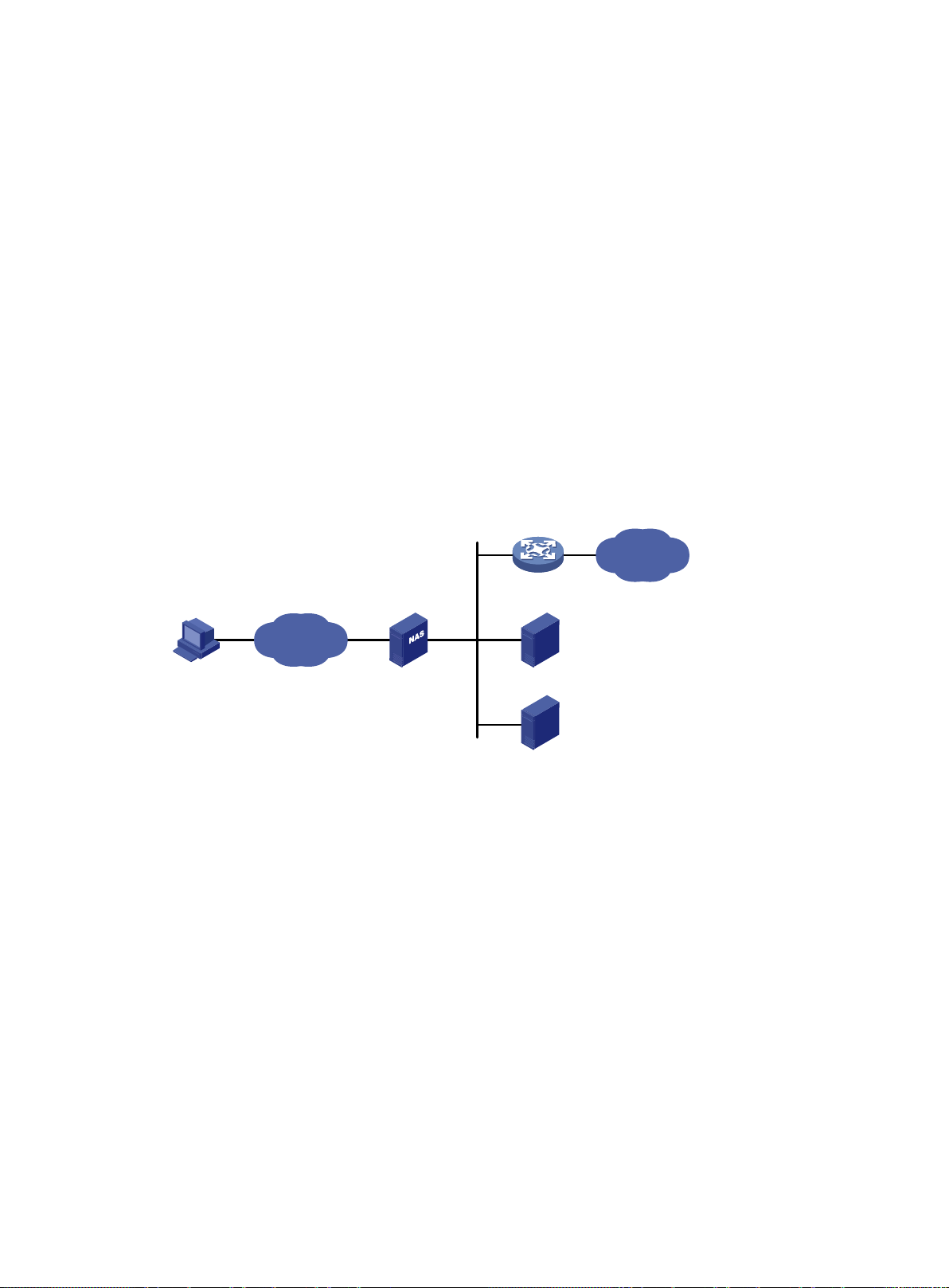
Configuring AAA
•
•
•
Remote user
NAS
RADIUS server
HWTACACS server
Internet
Network
Overview
Authentication, Authorization, and Accounting (AAA) provides a uniform framework for implementing
network access management. This feature specifies the following security functions:
Authentication—Identifies users and verifies their validity.
Authorization—Grants different users different rights, and controls the users' access to
resources and services. For example, you can permit office users to read and print files and
prevent guests from accessing files on the device.
Accounting—Records network usage details of users, including the service type, start time,
and traffic. This function enables time-based and traffic-based charging and user behavior
auditing.
AAA uses a client/server model. The client runs on the access device, or the network access server
(NAS), which authenticates user identities and controls user access. The server maintains user
information centrally. See Figure 1.
Figure 1 AAA network diagram
To access networks or resources beyond the NAS, a user sends its identity information to the NAS.
The NAS transparently passes the user information to AAA servers and waits for the authentication,
authorization, and ac coun ti ng r es ult. Based on t he r esult, the NAS determines whether to permit or
deny the access request.
AAA has various implementations , including RADIUS, HWTACACS, and LDAP. R ADIUS is most
often used.
The network in Figure 1 has one RADIUS server and one HWTACACS server. You can use different
servers to implement different security functions. For example, you can use the HWTACACS server
for authentication and authorization, and use the RADIUS server for accounting.
Yo u can choose th e security func tions provided by AA A as needed. For example, if your company
wants employees to be authenticate d before t hey access specific resources, you would deploy an
authentication server. If network usage information is needed, you would also configure an
accounting server.
The device performs dynamic password authentication.
1
Page 18

RADIUS
•
•
•
RADIUS servers
Users Clients Dictionary
Remote Authentication Dial-In User Service (RADIUS) is a distributed information interaction
protocol that uses a client/server model. The protocol can protect networks against unauthorized
access and is often used in net work environm ents that requir e both high security an d remote user
access.
The RADIUS authorizat io n proc es s is c om bined with t he RA DIUS authentication process, and user
authorization information is piggybacked in authentication responses. RADIUS uses UDP port 1812
for authentication and UDP port 1813 for accounting.
RADIUS was originally designed for dial-in user access, and has been extended to support
additional access methods, such as Ethernet and ADSL.
Client/server model
The RADIUS client runs on the NASs located throughout the network. It pass es user inf ormation to
RADIUS servers and acts on the responses to, for example, reject or accept user access requests.
The RADIUS server runs on the computer or workstation at the network center and maintains
information related to user authentication and network service access.
The RADIUS server operates using the following process:
1. Receives authentication, authorization, and accounting requests from RADIUS clients.
2. Performs user authentication, authorization, or accounting.
3. Returns user access control information (for example, rejecting or accepting the user access
request) to the clients.
The RADIUS server can also act as the cli ent of another RADIUS server to prov ide authenticati on
proxy services.
The RADIUS server maintains the following databases:
Users—Stores user information, such as the usernames, passwords, applied protocols, and IP
addresses.
Clients—Stores information about RADIUS clients, such as shared keys and IP addresses.
Dictionary—Stores RADIUS protocol attributes and their values.
Figure 2 RADIUS server databases
Information exchange security mechanism
The RADIUS client and server exchange information bet ween them with th e help of shared k eys,
which are preconfigured on the client and server. A RADIUS packet has a 16-byte field called
Authenticator. This field includes a signature generated by using the MD5 algorithm, the shared key,
and some other information. The receiver of the packet verifies the signature and accepts the packet
only when the signat ure is corr ect. T his m echanism ens ures the secur it y of inf orm ation exchan ged
between the RADIUS client and server.
The shared keys are also used to encrypt user passwords that are included in RADIUS packets.
User authentication methods
The RADIUS server supports multiple user authentication methods, such as PAP, CHAP, and EAP.
2
Page 19
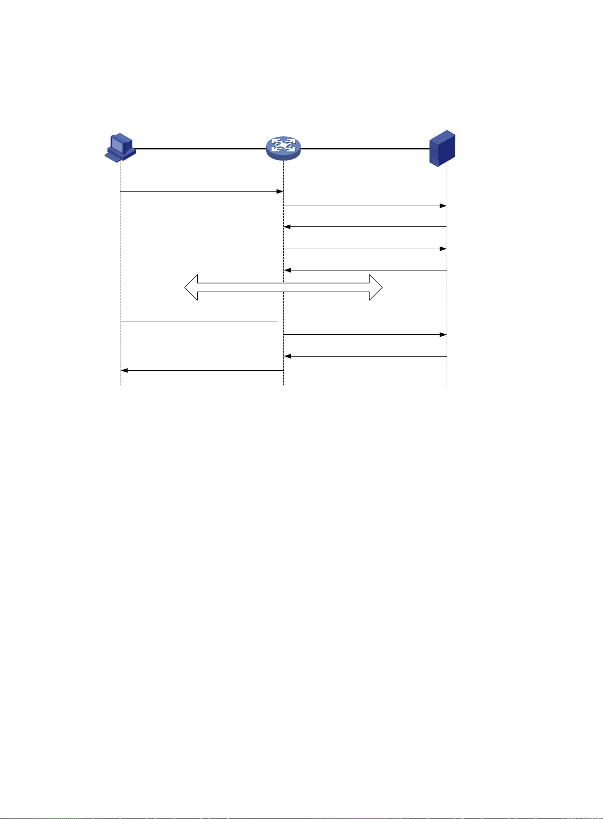
Basic RADIUS packet exchange process
RADIUS client
RADIUS server
1) Username and password
3) Access-Accept/Reject
2) Access-Request
4) Accounting-Request (start)
5) Accounting-Response
8) Accounting-Request (stop)
9) Accounting-Response
10) Notification of termination
Host
6) The host access the resources
7) Teardown request
Figure 3 illustrates the interactions between a user host, the RADIUS client, and the RADIUS server.
Figure 3 Basic RADIUS packet exchange process
RADIUS packet format
RADIUS uses in the following workflow:
1. The host sends a connection request that includes the user's username and password to the
RADIUS client.
2. The RADIUS client sends an authentication request (Access-Request) to the RADIUS server.
The request includes the user's password, which has been processed by the MD5 algorithm
and shared key.
3. The RADIUS server authenticates the username and password. If the authentication succeeds,
the server sends back an Access-Accept packet that contains the user's authorization
information. If the authentication fails, the server returns an Access-Reject packet.
4. The RADIUS client permits or denies the user according to the authentication result. If the result
permits the user, the RADIUS client sends a start-accounting request (Accounting-Request)
packet to the RADIUS server.
5. The RADIUS server returns an acknowledgment (Accounting-Response) packet and starts
accounting.
6. The user accesses the network resources.
7. The host requests the RADIUS client to tear do wn the c onnec ti on.
8. The RADIUS client sends a stop-accounting request (Accounting-Request) packet to the
RADIUS server.
9. The RADIUS server returns an acknowledgment (Accounting-Response) and stops accounting
for the user.
10. The RADIUS client notifies the user of the termination.
RADIUS uses UDP to transmit packets. T he protocol also uses a series of m echanisms to ensure
smooth packet exchange between the RADIUS server and the client. These mechanisms include the
timer mechanism, the retransmission mechanism, and the backup server mechanism.
3
Page 20

Figure 4 RADIUS packet format
•
Code
Packet type
Description
Name attribute and can optionally contain the attributes of
•
•
•
•
Code
Attributes
Identifier
0
7
Length
Authenticator (16bytes)
7 15 31
Descriptions of the fields are as follows:
The Code field (1 byte long ) indicates the type of the RADIUS packet. Table 1 gives the main
values and their meanings.
Table 1 Main values of the Code field
From the client to the server. A packet of this type includes user
1 Access-Request
information for the serv er t o authent icate th e user . It mu st con tain t he
UserNAS-IP-Address, User-Password, and NAS-Port.
From the server to the client. If all attribute values included in the
2 Access-Accept
3 Access-Reject
4
5
The Identifier field (1 byte lon g) is used to match response packets with request packets and to
Accounting-Reque
st
Accounting-Respo
nse
Access-Request are acceptable, the authentication succeeds, and
the server sends an Access-Accept response.
From the server to the client. If any attribute value included in the
Access-Request is unacceptable, the authentication fails, and the
server sends an Access-Reject response.
From the client to the server. A packet of this type includes user
information for the s erv er to start or s top accounting for the user. The
Acct-Status-Type attribute in the packet indicates whether to start or
stop accounting.
From the server to the c lient. The server sends a packet of this type to
notify the client that it has received the Accounting-Request and has
successfully recorded the accounting information.
detect duplicate request packets. The request and response packets of the same exchange
process for the same purpose (such as authentication or accounting) have the same identifier.
The Length field (2 bytes long) indicates the length of the entire packet (in bytes), including the
Code, Identifier, Length, Authenticator, and Attributes fields. Bytes beyond this length are
considered padding and are ignored by the receiver. If the length of a received packet is less
than this length, the packet is dropped.
The Authenticator field (16 bytes long) is used to authenticate responses from the RADIUS
server and to encrypt user passwords. There are two types of authenticators: request
authenticator and response authenticator.
The Attributes field (variable in length) includes authen tic ati on, aut hor izat io n, and ac c ounti ng
information. This field can contain multiple attributes, each with the following subfields:
Type—Type of the attribute.
4
Page 21

Length—Length of the attribute in bytes, including the Type, Length, and Value subfields.
No.
Attribute
No.
Attribute
Value—Value of the attribute. Its format and content depend on the Type subfield.
Commonly used RADIUS attributes are defined in RFC 2865, RFC 2866, RFC 2867, and RFC
2868. For more information, see "Commonly used standard RADIUS attributes."
Table 2 Commonly used RADIUS attributes
1 User-Name 45 Acct-Authentic
2 User-Password 46 Acct-Session-Time
3 CHAP-Password 47 Acct-Input-Packets
4 NAS-IP-Address 48 Acct-Output-Packets
5 NAS-Port 49 Acct-Terminate-Cause
6 Service-Type 50 Acct-Multi-Session-Id
7 Framed-Protocol 51 Acct-Link-Count
8 Framed-IP-Address 52 Acct-Input-Gigawords
9 Framed-IP-Netmask 53 Acct-Output-Gigawords
10 Framed-Routing 54 (unassigned)
11 Filter-ID 55 Event-Timestamp
12 Framed-MTU 56-59 (unassigned)
13 Framed-Compression 60 CHAP-Challenge
14 Login-IP-Host 61 NAS-Port-Type
15 Login-Service 62 Port-Limit
16 Login-TCP-Port 63 Login-LAT-Port
17 (unassigned) 64 Tunnel-Type
18 Reply-Message 65 Tunnel-Medium-Type
19 Callback-Number 66 Tunnel-Client-Endpoint
20 Callback-ID 67 Tunnel-Server-Endpoint
21 (unassigned) 68 Acct-Tunnel-Connection
22 Framed-Route 69 Tunnel-Password
23 Framed-IPX-Network 70 ARAP-Password
24 State 71 ARAP-Features
25 Class 72 ARAP-Zone-Access
26 Vendor-Specific 73 ARAP-Security
27 Session-Timeout 74 ARAP-Security-Data
28 Idle-Timeout 75 Password-Retry
29 Termination-Action 76 Prompt
30 Called-Station-Id 77 Connect-Info
31 Calling-Station-Id 78 Configuration-Token
32 NAS-Identifier 79 EAP-Message
5
Page 22

No.
Attribute
No.
Attribute
33 Proxy-State 80 Message-Authenticator
•
•
•
•
Type Length
0
Vendor-ID
7 15 31
Vendor-ID (continued) Vendor-Type Vendor-Length
Vendor-Data
(Specified attribute value……)
23
……
34 Login-LAT-Service 81 Tunnel-Private-Group-ID
35 Login-LAT-Node 82 Tunnel-Assignment-id
36 Login-LAT-Group 83 Tunnel-Preference
37 Framed-AppleTalk-Link 84 ARAP-Challenge-Response
38 Framed-AppleTalk-Network 85 Acct-Interim-Interval
39 Framed-AppleTalk-Zone 86 Acct-Tunnel-Packets-Lost
40 Acct-Status-Type 87 NAS-Port-Id
41 Acct-Delay-Time 88 Framed-Pool
42 Acct-Input-Octets 89 (unassigned)
43 Acct-Output-Octets 90 Tunnel-Client-Auth-id
44 Acct-Session-Id 91 Tunnel-Server-Auth-id
Extended RADIUS attributes
The RADIUS protoco l features excellent extensibility. The Vendor-Specific attri bute (attribute 26)
allows a vendor to define extended attributes. The extended attributes can implement functions that
the standard RADIUS protocol does not provide.
A vendor can encapsulate multiple subattributes in the TLV format in attribute 26 to provide extended
functions. As shown in Figure 5, a subattribute encapsulated in attribute 26 consists of the following
parts:
Vendor-ID—ID of the vendor. The most significant byte is 0. The other three bytes contains a
code compliant to RFC 1700.
Vendor-Type—Type of the subattribute.
Vendor-Length—Length of the subattribute.
Vendor-Data—Contents of the subattribute.
The device supports RADIUS subattributes with a vendor ID of 25506. For m ore information, see
"Proprietary RADIUS subattributes (vendor ID 25506)."
Figure 5 Format of attribute 26
HWTACACS
HW Terminal Access Controller Access Control System (HWTACACS) is an enhanced security
protocol based on TACACS (RFC 1492). HWT ACACS is similar to RADIUS, and uses a client/server
model for information exchange between the NAS and the HWTACACS server.
6
Page 23

HWTACACS typically provides AAA services for PPP, VPDN, and terminal users. In a typical
HWTACACS
RADIUS
Uses TCP, which provides reliable network
Encrypts the entire packet except for the
password field in an
authorization can be deployed on different
Protocol packets are simple and the authorization
roles and authorization. A user can use only
commands that are permitted by the user roles and
Access to commands solely depends
HWTACACS scenario, terminal users need to log in to the NAS. Working as the HWTACACS client,
the NAS sends users' usernames and passwords to the HWTACACS server for authentication. After
passing authentication an d obtaining authorized rights, a user logs in to the dev ice and performs
operations. The HWTACACS server records the operations that each user performs.
Differences between HWTACACS and RADIUS
HWTACACS and RADIUS have man y features in common, such as using a client/server model,
using shared keys for data encryption, and providing flexibility and scalability. Table 3 lists the
primary differences between HWTACACS and RADIUS.
Table 3 Primary differences between HWTACACS and RADIUS
transmission.
HWTACACS header.
Protocol packets are complicated and authorization
is independent of authentication. Authentication and
HWTACACS servers.
Supports authorization of configuration commands.
Access to commands depends on both the user's
authorized by the HWTACACS server.
Basic HWTACACS packet exchange process
Figure 6 describes how HWTACACS performs user authentication, authorization, and accounting for
a Telnet user.
Uses UDP, which provides high transport efficiency.
Encrypts only the user
authentication packet.
process is combined with the authentication
process.
Does not support authorization of configuration
commands.
on the user's roles. For more inform at io n abou t use r
roles, see Fundamentals Configuration Guide.
7
Page 24

Figure 6 Basic HWTACACS packet exchange process for a Telnet user
Host
HWTACACS client HWTACACS server
1) The user tries to log in
2) Start-authentication packet
3) Authentication response requesting the username
4) Request for username
5) The user enters the username
6) C ontinue-authentication packet with the username
7) Authentication response requesting the password
8) Request for password
9) The user enters the password
11) Response indicating successful authentication
12) User authorization request packet
13) Response indicating successful authorization
14) The user logs in successfully
15) Start-accounting request
16) Response indicating the start of accounting
17) The user logs off
18) Stop-accounting request
19) Stop-accounting response
10) C ontinue-a u th e n tic a tio n packet with the password
HWTACACS operates using in the following workflow:
1. A Telnet user sends an access request to the HWTACACS client.
2. The HWTACACS client sends a start-authentication packet to the HWTACACS server when it
3. The HWTACACS server sends back an authentication response to request the username.
4. Upon receiving the response, the HWTACACS client asks the user for the username.
5. The user enters the username.
6. After receiving the username from the user, the HWTACACS client sends the server a
7. The HWTACACS server sends back an authentication response to request the login password.
8. Upon receipt of the response, the HWTACACS client prompts the user for the login password.
9. The user enters the password.
receives the request.
continue-authentication packet that includes the username.
8
Page 25

10. After receiving the login password, the HWTACACS client sends the HWTACACS server a
•
•
•
•
•
11. If the authentication succeeds, the HWTACACS server sends back an authentication response
12. The HWTACACS client sends a user authorization request packet to the HWTACACS server.
13. If the authorization succeeds, the HWTACACS server sends back an authorization res pons e,
14. Knowing that the user is now authorized, the HWTACACS client pushes its CLI to the user and
15. The HWTACACS client sends a start-accounting request to the HWTACACS server.
16. The HWTACACS server sends back an accounting response, indicating that it has received the
17. The user logs off.
18. The HWTACACS client sends a stop-accounting request to the HWTACACS server.
19. The HWTACACS server sends back a stop-accounting response, indicating that the
LDAP
The Lightweight Directory Access Protocol (LDAP) provides standard multiplatform directory
service. LDAP was developed on the basis of the X.500 protocol. It improves the following functions
of X.500:
continue-authentication packet that includes the login password.
to indicate that the user has passed authentication.
indicating that the user is now authorized.
permits the user to log in.
start-accounting request.
stop-accounting request has been received.
Read/write interactive access.
Browse.
Search.
LDAP is suita ble for storing data that does not often change. The protocol is used to store user
information. For example, LDAP server software Active Directory Server is used in Microsoft
Windows operating s ystems. The software stores the user informat ion and user group infor mation
for user login authentication and authorization.
LDAP directory service
LDAP uses directories to maintain the organization information, personnel information, and resource
information. The directories are organized in a tree structure and include entries. An entry is a set of
attributes with distinguished names (DNs). The attributes are used to store inform ation such as
usernames, passwords, emails, computer names, and phone numbers.
LDAP uses a client/server model, and all directory information is stored in the LDAP server.
Commonly used LDAP server products include Microsoft Active Directory Server, IBM Tivoli
Directory Server, and Sun ONE Directory Server.
LDAP authentication and authorization
AAA can use LDAP to provide authentication and auth orization s ervices f or users. LDAP defines a
set of operations to implement its functions. The main operations for authentication and authorization
are the bind operation and search operation.
The bind operation allows an LDAP client to perform the following operations:
Establish a connection with the LDAP server.
Obtain the access rights to the LDAP server.
Check the validity of user information.
The search operation constructs search conditions and obtains the directory resource
information of the LDAP server.
In LDAP authentication, the client completes the following tasks:
9
Page 26
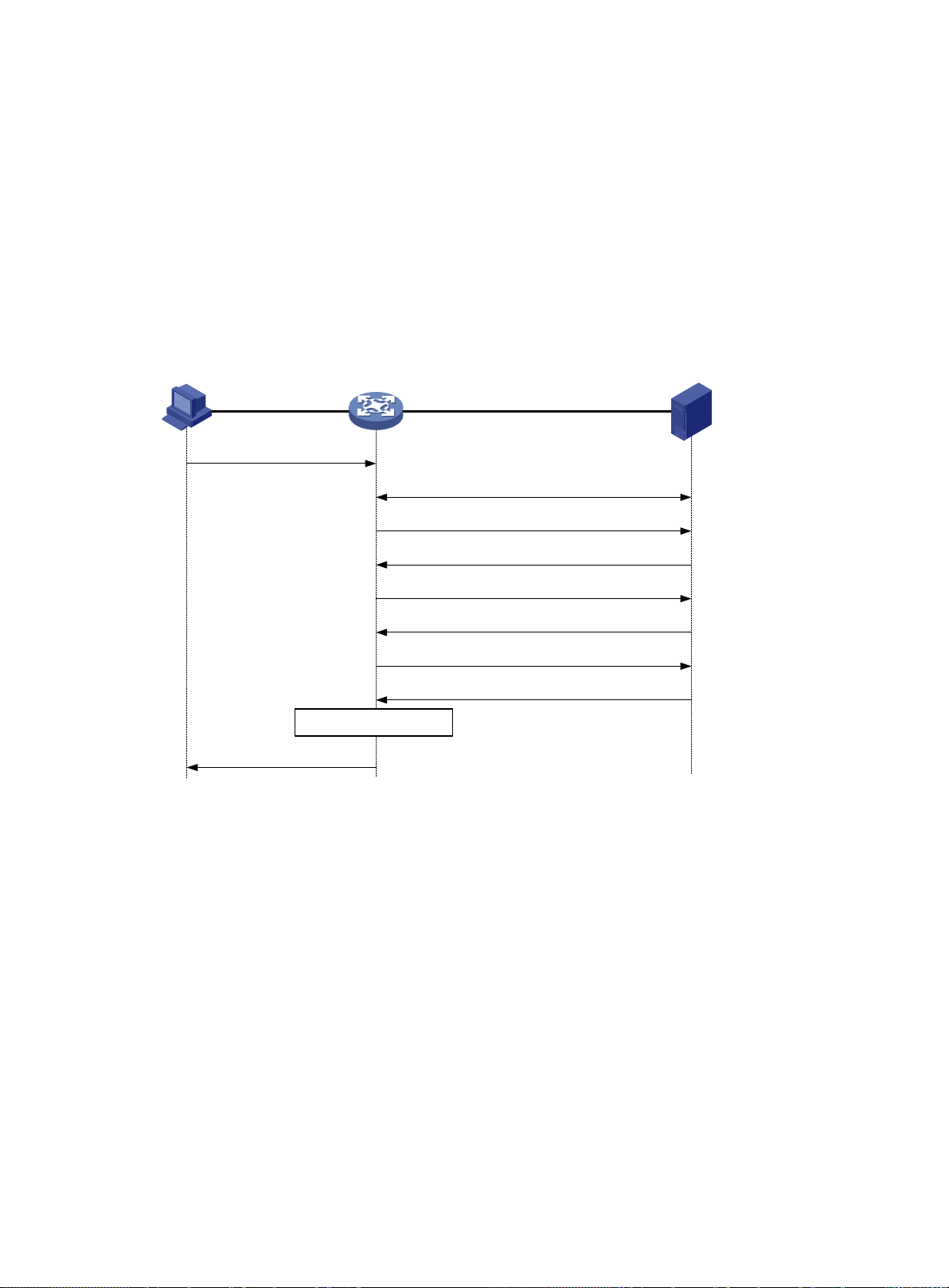
1. Uses the LDAP server administrator DN to bind with the LDAP server. After the binding is
3) Administrator bind request
4) Bind response
5) User DN search request
6) Search response
7) User DN bind request
8) Bind response
Host LDAP client LDAP server
10) The user logs in successfully
1) The user logs in by Telnet
2) Establish a TCP connection
9) Authorization process
created, the client establishes a connection to the server and obtains the right to search.
2. Constructs search conditions by using the username in the authentication information of a user.
The specified root directory of the server is searched and a user DN list is generat ed.
3. Binds with the LDAP server by using each user DN and password. If a binding is created, the
user is considered legal.
In LDAP authorization, th e client performs the sam e tasks as in LDAP authentication. When the
client constructs search conditions, it obtains both authorization information and the user DN list.
Basic LDAP authentication process
The following example illustrates the basic LDAP authentication process for a Tel net user.
Figure 7 Basic LDAP authentication process for a Telnet user
The following shows the basic LDAP authentication process:
1. A Telnet user initiates a connection request and sends the username and password to the
LDAP client.
2. After receiving the request, the LDAP client establishes a TCP connection with the LDAP
server.
3. To obtain the right to search, the LDAP client uses the administrator DN and password to send
an administrator bind request to the LDAP server.
4. The LDAP server processes the request. If the bind operation is successful, the LDAP server
sends an acknowledgment to the LDAP client.
5. The LDAP client sends a user DN search request with the username of the Telnet user to the
LDAP server.
6. After receiving the request, the LDAP server searches for the user DN by the base DN, search
scope, and filtering conditions. If a match is found, the LDAP server sends a response to notify
the LDAP client of the successful search. There might be one or more user DNs found.
7. The LDAP client uses the obtained user DN and the entered user password as parameters to
send a user DN bind request to the LDAP server. The server will check whether the user
password is correct.
10
Page 27
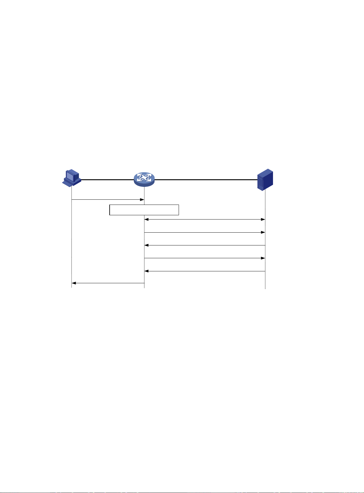
8. The LDAP server processes the request, and sends a response to notify the LDAP client of the
4) Administrator bind request
5) Bind response
6) User authorization search request
7) Search response
Host LDAP client LDAP server
8) The user logs in
successfully
1) The user logs in by Telnet
3) Establish a TCP connection
2) Authentication process
bind operation result. If the bind operation fails, the LDAP client uses another obtained user DN
as the parameter to send a user DN bind request to the LDAP server. This process continues
until a DN is bound successfully or all DNs fail to be bound. If all user DNs fail to be bound, the
LDAP client notifies the user of the login failure and denies the user's access request.
9. The LDAP client saves the user DN that has been bound and exchanges authorization packets
with the authorization serve r.
If LDAP authorization is used, see the authorization process shown in Figure 8.
If another method is expected for authorization, the authorization process of that method
applies.
10. After successful authorization, the LDAP client notifies the user of the successful login.
Basic LDAP authorization process
The following example illustrates the basic LDAP authorization process for a Telnet user.
Figure 8 Basic LDAP authorization process for a Telnet user
The following shows the basic LDAP authorization process:
1. A Telnet user initiates a connection request and sends the username and password to the
device. The device will act as the LDAP client during authorization.
2. After receiving the request, the device exchanges authentication packets with the
authentication server for the user:
If LDAP authentication is used, see the authentication process shown in Figure 7.
− If the device (the LDAP client) uses the same LDAP server for authentication and
authorization, skip to step 6.
− If the device (the LDAP client) uses different LDAP servers for authentication and
authorization, skip to step 4.
If another authentication method is used, the authentication process of that method applies.
The device acts as the LDAP client. Skip to step 3.
3. The LDAP client establishes a TCP connection with the LDAP authorization server.
4. To obtain the right to search, the LDAP client uses the administrator DN and password to send
an administrator bind request to the LDAP server.
5. The LDAP server processes the request. If the bind operation is successful, the LDAP server
sends an acknowledgment to the LDAP client.
11
Page 28
6. The LDAP client sends an authorization search request with the username of the Telnet user to
Username contains
@domain-name?
A user enters the
username in the form
userid@domain-name
or userid
The user belongs to
domain domain-name.
The user belongs to the
default domain.
Yes
No
NAS
•
•
•
•
•
•
•
•
•
domains for users of the access types depend on the configuration of the authentication modules.
the LDAP server. If the user uses the same LDAP server for authentication and authorization,
the client sends the request with the saved user DN of the Telnet user to the LDAP server.
7. After receiving the request, the LDAP server searches for the user information by the base DN,
search scope, filtering conditions, and LDAP attributes. If a match is found, the LDAP server
sends a response to notify the LDAP client of the successful search.
8. After successful authorization, the LDAP client notifies the user of the successful login.
AAA implementation on the device
This section describes AAA user management and methods.
User management based on ISP domains and user access types
AAA manages users based on the users' ISP domains and access types.
On a NAS, each user belon gs to one ISP domain. The NAS determines the I SP dom ain to which a
user belongs based on the username entered by the user at login.
Figure 9 Determining the ISP domain for a user by username
AAA manages users in the same ISP domain based on the users' access types. The device supports
the following user access types:
LAN—LAN users must pass 802.1X or MAC authentication to come online.
Login—Login users include SSH, Telnet, FTP, and terminal users who log in to the device.
Terminal users can access through a console, AUX, or Async port.
ADVPN.
X.25 PAD.
Portal—Portal users must pass portal authentication to access the network.
PPP.
IPoE—IPoE users include Layer 2 and Layer 3 leased line users and Set Top Box (STB) users.
IKE—IKE users must pass IKE extended authentication to access the network.
Web—Web users log in to the Web interface of the device through HTTP or HTTPS.
NOTE:
The device also provides authentication modules (such as 802.1X) for implementation of user
authentication management policies. If you configure these authentication modules, the ISP
12
Page 29

AAA methods
•
•
•
•
•
•
•
•
•
•
AAA supports configuring different authentication, authorization, and accounting methods for
different types of users in an ISP domain. The NAS determines the ISP domain and access type of a
user. The NAS also uses the m ethods configured f or the access t ype in the domain to contr ol the
user's access.
AAA also supports configuring a set of def ault m ethods f or an ISP domain. T hese def ault methods
are applied to users for whom no AAA methods are configured.
The device supports the following authentication methods:
No authentication—This method trusts all users and does not perform authentication. For
security purposes, do not us e this method.
Local authentication—The NAS authenticates users by itself, based on the locally configured
user information including the usernames, passwords, and attributes. Local authentication
allows high speed and low cost, but the amount of information that can be stored is limited by
the size of the storage space.
Remote authentication—The NAS works with a RADIUS, HWTACACS, or LDAP server to
authenticate users. The server manages user information in a centralized manner. Remote
authentication provides high capacity, reliable, and centralized authentication services for
multiple NASs. You can configure backup methods to be used when the remote server is not
available.
The device supports the following authorization methods:
No authorization—The NAS performs no authorization exchange. The following default
authorization inform ation applies after users pass authentication:
Non-login users can access the network.
Login users obtain the default user role. For more information about the default user role
The working directory for FTP, SFTP, and SCP login users is the root directory of the NAS.
Local authorization—The NAS performs authorization according to the user attributes locally
configured for users.
Remote authorization—The NAS works with a RADIUS, HWTACACS, or LDAP server to
authorize users. RADIUS authorization is bound with RADIUS authentication. RADIUS
authorization can work only after RADIUS authentication is successful, and the authorization
information is included in the Access-Accept packet. HWTACACS authorization is separate
from HWTACACS authentication, and the authorization information is included in the
authorization response after successful authentication. You can configure backup methods to
be used when the remote server is not available.
feature, see Fundamentals Configuration Guide.
However, the users do not have permission to access the root directory.
The device supports the following accounting methods:
No accounting—The NAS does not perform accounting for the users.
Local accounting—Local accounting is implemented on the NAS. It counts and controls the
number of concurrent users who use the same local user account, but does not provide
statistics for charging.
Remote accounting—The NAS works with a RADIUS server or HWTACACS server for
accounting. You can configure backup methods to be used when the remote server is not
available.
In addition, the device provides the following login services to enhance device security:
Command authorization—Enables the NAS to let the authorization server determine whether
a command entered by a login user is permitted. Login users can execute only commands
permitted by the authorization server. For more information about command authorization, see
Fundamentals Configuration Guide.
13
Page 30

•
•
•
•
•
•
•
•
•
•
•
P
MPLS backbone
PE
PE
CE
CE
CE
VPN 1
VPN 2
VPN 3
RADIUS
server
HWTACACS
server
Host
Host
NAS
Command accounting—When command authorization is disabled, command accounting
enables the accounting server to record all valid commands executed on the device. When
command authorization is enabled, command accounting enables the accounting server to
record all authorized commands. For more information about command accounting, see
Fundamentals Configuration Guide.
User role authentication—Authenticates each user who wants to obtain another user role
without logging out or getting disconnected. For more information about user role
authentication, see Fundamentals Configuration Guide.
AAA for MPLS L3VPNs
Yo u can d eploy AAA across VPNs in an MPLS L3VPN scenario where c l ient s in d iffer ent VPN s ar e
centrally authenticated. The dep loyment enables for warding of RADIUS a nd HWTACACS packets
across MPLS VPNs. For example, as show n in Figure 10, you can deploy AAA across the VPNs. The
PE at the left side of the MPL S backbone acts as a NAS. The NAS transparen tly deli vers the A AA
packets of private users in VPN 1 and VPN 2 to the AAA servers in VPN 3 for centralized
authentication. Authentication packets of private users in different VPNs do not affect each other.
Figure 10 Network diagram
This feature can also help an MCE to implement portal authentication for VPNs. For more
information about MCE, see MPLS Configuration Guide. For more information about portal
authentication, see "Configuring portal authentication."
Protocols and standards
RFC 2865, Remote Authentication Dial In User Service (RADIUS)
RFC 2866, RADIUS Accounting
RFC 2867, RADIUS Accounting Modifications for Tunnel Protocol Support
RFC 2868, RADIUS Attributes for Tunnel Protocol Support
RFC 2869, RADIUS Extensions
RFC 5176, Dynamic Authorization Extensions to Remote Authentication Dial In User Service
(RADIUS)
RFC 1492, An Access Control Protocol, Sometimes Called TACACS
RFC 1777, Lightweight Directory Access Protocol
RFC 2251, Lightweight Directory Access Protocol (v3)
14
Page 31

RADIUS attributes
No.
Attribute
Description
Digest of the user password for CHAP authentication, only present in
identified by the IP address of its access interface. This attribute is only
Type of service that the user has requested or type of service to be
For example, this
attribute can be used to define the maximum size of EAP packets
Text to be displayed to the user, which can be used by the server to
specific proprietary attribute. A packet can contain one or more
proprietary attributes, each of which can contain one or more
Maximum idle time permitted for the user before termination of the
User identification t hat th e N A S sen ds to the s er v er. F or th e LAN access
device, this attribute includes the MAC
the 3rd Generation Partnership
the 3rd Generation Partnership
Commonly used standard RADIUS attributes
1 User-Name Name of the user to be authenticated.
2 User-Password
3 CHAP-Password
4 NAS-IP-Address
5 NAS-Port Physical port of the NAS that the user accesses.
6 Service-Type
7 Framed-Protocol Encapsulation protocol for framed access.
8 Framed-IP-Address IP address assigned to the user.
11 Filter-ID Name of the filter list.
12 Framed-MTU
14 Login-IP-Host IP address of the NAS interface that the user accesses.
15 Login-Service Type of the service that the user uses for login.
18 Reply-Message
User password for PAP authentication, only present in Access-Request
packets when PAP authentication is used.
Access-Request packets when CHAP authenti cat ion is used .
IP address for the server to us e t o id entify th e cl ien t. T y picall y , a clie nt i s
present in Access-Request packets.
provided.
MTU for the data link between the user and NAS.
allowed to be processed in 802.1X EAP authentication.
communicate information, for example, the reason of the authentication
failure.
Vendor-
26 Vendor-Specific
subattributes.
27 Session-Timeout Maximum service duratio n for t he user be fore t erminat ion of the se ssion .
28 Idle-Timeout
31 Calling-Station-Id
32 NAS-Identifier Identification that the NAS uses to identify itself to the RADIUS server.
40 Acct-Status-Type
session.
service provided by an HPE
address of the user in the format HHHH-HHHH-HHHH.
Type of the Accounting-Request packet. Possible values include:
• 1—Start.
• 2—Stop.
• 3—Interim-Update.
• 4—Reset-Charge.
• 7—Accounting-On. (Defined in
Project.)
• 8—Accounting-Off. (Defined in
Project.)
• 9 to 14—Reserved for tunnel accounting.
• 15—Reserved for failed.
15
Page 32

No.
Attribute
Description
45 Acct-Authentic
NAS for MD5 calculation during
physical port of the NAS that is authenticating the user.
to allow RADIUS to support EAP
Used for authentication and verification of authentication packets to
No.
Subattribute
Description
Operation for the session, used for session control. Possible values
Authentication method used by the user. Possible values include:
• 1—RADIUS.
• 2—Local.
• 3—Remote.
60 CHAP-Challenge
61 NAS-Port-Type
79 EAP-Message
80
87 NAS-Port-Id String for describing the port of the NAS that is authenticating the user.
Message-Authenticato
r
CHAP challenge generated by the
CHAP authentication.
Type of the
Possible values include:
• 15—Ethernet.
• 16—Any type of ADSL.
• 17—Cable. (With cable for cable TV.)
• 19—WLAN-IEEE 802.11.
• 201—VLAN.
• 202—ATM.
If the port is an ATM or Ethernet one and VLANs are implemented on it,
the value of this attribute is 201.
Used to encapsulate EAP packets
authentication.
prevent spoofing Access-Requests. This attribute is present when EAP
authentication is used.
Proprietary RADIUS subattributes (vendor ID 25506)
1 Input-Peak-Rate Peak rate in the direction from the user to the NAS, in bps.
2 Input-Average-Rate Average rate in the direction from the user to the NAS, in bps.
3 Input-Basic-Rate Basic rate in the direction from the user to the NAS, in bps.
4 Output-Peak-Rate Peak rate in the direction from the NAS to the user, in bps.
5 Output-Average-Rate Average rate in the direction from the NAS to the user, in bps.
6 Output-Basic-Rate Basic rate in the direction from the NAS to the user, in bps.
15 Remanent_Volume
20 Command
Total amount of data available for the connection, in different units for
different server types.
include:
• 1—Trigger-Request.
• 2—Terminate-Request.
• 3—SetPolicy.
• 4—Result.
• 5—PortalClear.
16
Page 33

No.
Subattribute
Description
24 Control_Identifier
the same value. For
packet must also include this attribute and the value of this attribute
. A
Information that must be sent from the server to the client
Hash value assigned after an 802.1X user passes authentication,
Identification for retr ansmitted pac kets. For retra nsmitted pac kets from
the same session, this attribute must be
retransmitted packets from different sessions, this attribute does not
have to be the same value. The client response of a retransmitted
must be the same.
For Accounting-Request p ac k ets of the start, stop, and interim update
types, the Control_Identifier attribute does not take effect.
25 Result_Code
26 Connect_ID Index of the user connection.
28 Ftp_Directory
29 Exec_Privilege EXEC user priority.
59 NAS_Startup_Timestamp
60 Ip_Host_Addr
61 User_Notify
62 User_HeartBeat
201 Input-Interval-Octets Number of bytes input within a real-time accounting interval.
202 Output-Interval-Octets Number of bytes output within a real-time accounting interval .
Result of the Trigger-Request or SetPolicy oper ation, z ero for success
and any other value for failure.
FTP, SFTP, or SCP user working directory.
When the RADIUS client acts as the FTP, SFTP, or SCP server, this
attribute is used to set the w orking d irectory for an FTP, SFTP, or SCP
user on the RADIUS client.
Startup time of the NAS in seconds, which is represented by the time
elapsed after 00:00:00 on Jan. 1, 1970 (UTC).
User IP address and MAC address included in authentication and
accounting requests, in the format A.B.C.D hh:hh:hh:hh:hh:hh
space is required between the IP address and the MAC address.
transparently.
which is a 32-byte string. This attribute is stored in the user list on the
NAS and verifies the handshake packets from the 802.1X user. This
attribute only exists in Access-Accept and Accounting-Request
packets.
203 Input-Interval-Packets
204 Output-Interval-Packets
205 Input-Interval-Gigawords
206
207 Backup-NAS-IP Backup source IP address for sending RADIUS packets.
255 Product_ID Product name.
Output-Interval-Gigawords Amount of bytes output wi thin an account ing interval, in units of 4G
Number of packets input within an accounting int erval in the u nit set on
the NAS.
Number of packets output within an accounting interval in the unit set
on the NAS.
Amount of bytes input within an accounting interval, in units of 4G
bytes.
bytes.
FIPS compliance
The device supports the F I PS mode that complies wit h NIST FIPS 140-2 r equire ments. Support for
features, commands, and parameters might differ in FIPS mode (see "Configuring FIPS") and
non-FIPS mode.
17
Page 34

AAA configuration considerations and task list
Tasks at a glance
to configure AAA authentication,
Configure the RADIUS, HWTACACS,
or LDAP schemes to be used
none/ local (the default)/scheme
Authorization method
Accounting method
Configure AAA methods for
different types of users or/and
the default methods for all
types of users
Create an ISP domain
and enter ISP domain
view
Authentication method
Configure local users and related
attributes
none/ local (the default)/scheme
+
+
Local AAA
Remote AAA
No AAA
none/ local (the default)/scheme
T o configure AAA, complete the following tasks on the NAS:
1. Configure the required AAA schemes:
Local authentication—Configure local users and the related attributes, including the
usernames and passwords, for the users to be authenticated.
Remote authentication—Configure the required RADIUS, HWTACACS, and LDAP
schemes.
2. Configure AAA methods for the users' ISP domains. Remote AAA methods need to use the
configured RADIUS, HWTACACS, and LDAP schemes.
Figure 11 AAA configuration procedure
To configure AAA, perform the following tasks:
(Required.) Perform a minimum one of the following tasks to configure local users or AAA schemes:
• Configuring local users
• Configuring RADIUS schemes
• Configuring HWTACACS schemes
• Configuring LDAP schemes
(Required.) Configure AAA methods for ISP domains:
1. (Required.) Creating an ISP domain
2. (Optional.) Configuring ISP domain attributes
3. (Required.) Perform a minimum one of the following tasks
authorization, and accounting methods for the ISP domain:
Configuring authentication methods for an ISP domain
Configuring authorization methods for an ISP domain
Configuring accounting methods for an ISP domain
(Optional.) Configuring the ses sion-control feature
(Optional.) Configuring the RADIUS DAE server feature
(Optional.) Changing the DSCP priority for RADIUS packets
18
Page 35

Tasks at a glance
(Optional.) Setting the maximum number of concurrent login users
•
•
•
•
•
•
•
•
(Optional.) Configuring and applying an ITA policy
(Optional.) Configuring a NAS-ID profile
(Optional.) Configuring the device ID
Configuring AAA schemes
This section includes information on configuring local users, RADIUS schemes, HWTACACS
schemes, and LDAP schemes.
Configuring local users
To im plement local authent ication, authori zation, and account ing, create loca l users and configure
user attributes on the device. The local users and attributes are stored in the local user database on
the device. A local user is unique ly identified by the com bination of a usernam e and a user type.
Local users are classified into the following types:
Device management user—User who logs in to the device for device management.
Network access user—User who accesses network resources through the device. Network
access users also include guests who access the network temporarily. Guests can use LAN
and portal services only.
The following shows the configurable local user attributes:
Service type—Services that the user can use. Local authentication checks the service types of
a local user. If none of the service types is available, the user cannot pass authentication.
Service types include ADVPN, FTP, HTTP, HTTPS, IKE, IPoE, LAN access, PAD, portal, PPP,
SSH, Telnet, and terminal.
User state—Whether or not a local user can request network services. There are two user
states: active and blocked. A user in active state can request network services, but a user in
blocked state cannot.
Upper limit of concurrent logins using the same user name—Maximum number of users
who can concurrently access the device by using the same user name. When the number
reaches the upper limit, no more local users can access the device by using the user name.
User group—Each local user belongs to a local user group and has all attributes of the group.
The attributes include the password control attributes and authorization attributes. For more
information about local user group, see "Configuring user group attributes."
Binding attributes—Binding attributes control the scope of users, and are checked during
local authentication of a user. If the attributes of a user do not match the binding attributes
configured for the local user account, the user cannot pass authentication. Binding attributes
include the ISDN calling number, IP address, access port, MAC address, and native VLAN. For
support and usage information about binding attributes, see "Configuring local user attributes."
Authorization attributes—Authorization attributes indicate the user's rights after it passes
local authentication. For support information about authorization attributes, see "Configuring
local user attributes."
Configure the authorization attributes based on the service type of local users. For example,
you do not need to configure the FTP/SFTP/SCP working directory attribute for a PPP user.
You can configure an authorization attribute in user group view or local user view. The setting of
an authorization attribute in local user view takes precedence over the attribute setting in user
group view.
19
Page 36

The attribute configured in user group view takes effect on all local users in the user group.
•
Tasks at a glance
•
•
•
Step
Command
Remarks
The attribute configured in local user view takes effect only on the local user.
Password control attributes—Password control attributes help control password security for
device management users. Password control attributes include password aging time, minimum
password length, password composition checking, password complexity checking, and login
attempt limit.
You can configure a password control attribute in system view, user group view, or local user
view. A password control attribute with a smaller effective range has a higher priority. For more
information about password management and global password configuration, see "Configuring
password control."
Local user configuration task list
(Required.) Configuring local user attributes
(Optional.) Configuring user group attributes
(Optional.) Configuring local g uest attri but e s
(Optional.) Managing local guests
(Optional.) Displaying and mai ntain ing lo cal user s and loca l user group s
Configuring local user attributes
When you configure local user attributes, follow these guidelines:
When you use the password-control enable command to globally enable the password
control feature, local user passwords are not displayed.
You can configure authorization attributes and password control attributes in local user view or
user group view. The setting in local user view takes precedence over the setting in user group
view.
Configure the location binding attribute based on the service types of users.
For 802.1X users, specify the 802.1X-enabled Layer 2 Ethernet interfaces through which
the users access the device.
For MAC authentication users, specify the MAC authentication-enabled Layer 2 Ethernet
interfaces through which the users access the device.
For portal users, specify the portal-enabled interfaces through which the users access the
device. Specify the Layer 2 Ethernet interfaces if portal is enabled on VLAN interfaces and
the portal roaming enable command is not configured.
To configure local user attributes:
4. Enter system view.
5. Add a local user and
enter local user view.
system-view
local-user
manage | network
{
user-name [
} ]
class
N/A
By default, no local users exist.
20
Page 37

Step
Command
Remarks
6. (Optional.) Configure
a password for the
In FIPS mode, no password is
configured for a local user. A local
For a device management
Place the
(Optional.) Set the
limit of
using the local user
users, who do not
binding attributes for
By default, no binding attributes are
(Optional.) Configure
do not have permission to
assigned to local users that are
admin or
local user.
7. Assign services to the
local user.
8. (Optional.)
local user to the activ e
or blocked state.
• For a network access user:
password { cipher | simple }
string
• For a device management
user:
In non-FIPS mode:
password [ { hash |
simple } string ]
In FIPS mode:
password
• For a network access user:
service-type { advpn | ike |
ipoe | lan-access | portal |
ppp }
•
user:
In non-FIPS mode:
service-type { ftp | { http |
https | pad | ssh | telnet |
terminal } * }
In FIPS mode:
service-type { https | pad
| ssh | terminal } *
state { active | block
}
The default settings are as follows:
• In non-FIPS mode, no p as sw or d is
configured for a local user. A local
user can pass authentication after
entering the correct userna me and
passing attribute checks.
•
user cannot pass authentication.
By default, no services are authorized
to a local user.
By default, a local user is in active state
and can request network services.
9.
upper
concurrent logins
name.
10. (Optional.) Configure
the local user.
11.
authorization
attributes for the local
user.
access-limit
bind-attribute
max-user-number
call-number
{
call-number [ : subcall-number ] |
ip
ip-address |
location interface
interface-type interface-number |
mac
mac-address |
authorization-attribute
acl-number |
callback-number |
ip
ipv4-address |
ipv4-pool-name |
ipv6-address |
ipv6-pool-name |
vlan
vlan-id } *
acl
{
callback-number
idle-cut
minute |
ip-pool
ipv6
ipv6-pool
ipv6-prefix
ipv6-prefix prefix-length |
primary-dns
{
{ ip ipv4-address |
ipv6-address } |
minutes |
user-profile
user-role
|
secondary-dns
|
session-timeout
url
url-string |
profile-name |
role-name |
vlan
vlan-id
vpn-instance
}
ipv6
vpn-instance-name |
work-directory
directory-name } *
By default, the number of concurrent
logins is not limited for the local user.
This command takes effect only when
local accounting is configured for the
local user. It does not apply to FTP,
SFTP, or SCP
support accounting.
configured for a local user.
The following default settings apply:
• The working directory for FTP,
SFTP, and SCP users is the root
directory of the N AS . However, the
users
access the root directory.
• The network-operator user role is
created by a network-
level-15 user.
21
Page 38

Step
Command
Remarks
12.
(Optional.) Configure
password control
the minimum password
control length
Configure the password
attempts and the action to
By default, the local user uses
password control attributes of the user
cal user to a user
(Optional.) Configure
a description for the
Step
Command
Remarks
Create a user group and
group exists. The group
attributes for the local
user.
13. (Optional.) Assign the
lo
group.
• Set the password aging time:
password-control aging
aging-time
• Set
length:
password-
length
• Configure the password
composition policy:
password-control
composition type-number
type-number [ type-length
type-length ]
•
complexity checking policy:
password-control
complexity
{ same-character |
user-name } check
• Configure the maximum login
take if there is a login failure:
password-control
login-attempt login-times
[ exceed { lock | lock-time
time | unlock } ]
group
group-name
group to which the local user belongs.
Only device management users support
the password control feature.
By default, a local user belongs to the
user group
system
.
14.
local user.
Configuring user group attributes
User groups simplif y local user configuration and m anagement. A user group contains a group of
local users and has a set o f local user attr ibutes. You can configure local user attr ibutes f or a user
group to implem ent centralized us er attribut es managem ent for the local users in the group. Local
user attributes that are manageable include authorization attributes.
By default, ever y new loca l us er belo ngs to the d efault user gr oup system and has all attributes of
the group. To assign a local user t o a different user group, use the group comm and in local user
view.
To configure user group attributes:
15. Enter system view.
16.
enter user group view.
description
system-view
user-group
text
group-name
By default, a local user does not have a
description.
This command is applicable to network
access users.
N/A
By default, a system-defined
user
name is system.
22
Page 39

Step
Command
Remarks
17.
Configure authorization
for the user
y default, no authorization
attributes are configured for a
(Optional.) Configure
the minimum password
Configure the password
Configure the maximum login
global password control
"Configuring password
Step
Command
Remarks
guest and
By default, no password is
a description for
By default, no description is
attributes
group.
18.
password control attributes
for the user group.
authorization-attribute
acl-number |
callback-number |
ip-pool
ipv6-pool-name |
ipv6-prefix prefix-length |
{
{
ipv6-address } |
minutes |
profile-name |
vpn-instance
work-directory
• Set the password aging time:
• Set
• Configure the password
•
•
ipv4-pool-name |
primary-dns
ip
ipv4-address |
password-control aging
aging-time
length:
password-control length
length
composition policy:
password-control
composition type-number
type-number [ type-length
type-length ]
complexity checking policy:
password-control complexity
{ same-character |
user-name } check
attempts and the action to take
for login failures:
password-control
login-attempt login-times
[ exceed { lock | lock-time time
| unlock } ]
|
url
url-string |
vpn-instance-name |
directory-name } *
{
callback-number
idle-cut
ipv6-prefix
secondary-dns
session-timeout
user-profile
vlan
vlan-id |
acl
minute |
ipv6-pool
}
ipv6
B
user group.
By default, the user group uses
the
settings. For more information,
see
control."
Configuring local guest attributes
Create local guests and c onfigure guest attributes to contr ol temporary network acces s behavior.
Guests can access th e network after passing local authentic ation. You can configure the recipient
addresses and send attribute information to the local guests and guest sponsors by email.
To configure local guest attributes:
19. Enter system view.
20. Create a local
enter local guest view.
21. Configure a password for the
local guest.
22. Configure
the local guest.
23. Specify the name of the local
guest.
system-view
local-user
network guest
password
string
description
full-name
user-name
{
text
name-string
23
cipher
simple
|
class
}
N/A
By default, no local guests exist.
configured for a local guest.
configured for a local guest.
By default, no name is specified for
a local guest.
Page 40

Step
Command
Remarks
24. Specify the company of the
By default, no phone number is
By default, no email address is
Specify the sponsor name
By default, no sponsor name is
Specify the sponsor
department for the local
By default, no sponsor department
Specify the sponsor email
By default, no sponsor email
By default, a local guest does not
Assign the local guest to a
defined user group
•
•
•
•
•
•
local guest.
25. Specify the phone number of
the local guest.
company
phone
phone-number
company-name
By default, no company is specified
for a local guest.
specified for a local guest.
26. Specify the email address of
the local guest.
27.
for the local guest.
28.
guest.
29.
address for the local guest.
30. Configure the validity period
for the local guest.
31.
user group.
email
email-string
sponsor-full-name
name-string
sponsor-department
department-string
sponsor-email
validity-datetime
start-time to expiration-date
expiration-time
group
group-name
email-string
start-date
specified for a local guest.
The device sends email notification s
to this address to inform the guest of
the account information.
specified for a local guest.
is specified for a local guest.
address is specified for a local
guest.
The device sends email notifi cat ions
to this address to inform the sponsor
of the guest information.
expire.
Expired guests cannot pass local
authentication.
By default, a local guest belongs to
the system-
system
.
Managing local guests
The local guest management features are for registration, approval, maintenance, and access
control of local guests.
The device provides the following local guest management features:
Guest auto-delete—The device checks the validity status of each local guest and
automatically deletes expired local guests.
Registration and approval—The device creates local guests after the guest registration
information is approved by a guest manager.
Email notification—The device notifies the local guests, guest sponsors, or guest managers
by email of the guest account information or guest registration requests.
Local guest creation in batch—Create a batch of local guests.
Local guest import—Import guest account information from a .csv file to create local guests
on the device based on the imported information.
Local guest export—Export local guest account information to a .csv file. You can import the
account information to other devices as needed.
The registration and approval processes are as follows:
1. The device pushes the portal user registration page to a user who wants to access the network
as a local guest.
2. The user submits account information for registration, including the user name, password, and
email address.
3. The device forwards the registration request to the guest manager in an email notification.
24
Page 41

4. The guest manager adds supplementary information as needed and approves the registration
Step
Command
Remarks
Configure the subject and
By default, no subject and body
the email sender
address in the email
notifications sent by the
By default, no email sender
address is configured for the
ications sent by the
By default, no SMTP server is
Configure the guest
By default, the guest manager's
(Optional.) Set the
approval timeout
timer for guest registration
guest timer
account information from
path to create local guests
based on the imported
import class
(Optional.) Create local
guest generate
Batch generated local guests
can also configure a password
(Optional.) Export local
export class
information.
The guest manager must process the registration request before the waiting-approval timeout
timer expires. The device automatically deletes expired registration request information.
5. The device creates a local guest account and sends an email notification to the user and guest
sponsor. The email contains local guest account, password, validity period, and other account
information.
The user can access the network as a local guest.
To manage local guests:
32. Enter system view
33.
body of email notifications.
34. Configure
device for local guests.
35. Specify an SMTP server for
sending email notifications of
local guests.
36.
manager's email address.
37.
waitingrequests.
38. (Optional.) Import guest
a .csv file in the specified
information.
system-view
local-guest email format to
guest
{
body
{
sub-string }
local-guest email sender
email-address
local-guest email smtp-server
url-string
local-guest manager-email
email-address
localwaiting-approval
local-usernetwork guest url
validity-datetime
start-time
expiration-time
auto-create-group
[
start-line
manager
|
body-string |
line-number ] *
|
time-value
start-date
to
expiration-date
|
sponsor
subject
url-string
override
N/A
}
are configured.
email notif
device.
specified.
email address is not configured.
The default is 24 hours.
N/A
|
39.
guests in batch.
40.
guest account information to
a .csv file in the specified
path.
41. (Optional.) Enable the guest
auto-delete feature.
42. Return to user view.
localusername-prefix
[
password-prefix ]
suffix-number [
group-name ]
validity-datetime
start-time
expiration-time
local-usernetwork guest url
local-guest auto-delete enable
quit
name-prefix
password-prefix
count
user-count
start-date
to
expiration-date
url-string
25
suffix
group
share the same name prefix. You
prefix to be shared by the guests.
N/A
By default, the guest auto-delete
feature is disabled.
N/A
Page 42

Step
Command
Remarks
43.
Send email notifications to
The email contents include the
local user
Display user group
Display pending registration
Clear pending registration
Tasks at a glance
the local guest or the guest
sponsor.
local-guest send-email
user-name
sponsor }
|
user-name to {
guest
Displaying and maintaining local users and local user groups
Execute display commands in any view.
Task Command
user name, password, and va lidity
period of the guest account.
display local-user
Display the
configuration and online user
statistics.
configuration.
requests for local guests.
requests for local guests.
enable
lan-access
block
vlan-id ]
display user-group
display local-guest waiting-approval
reset local-guest waiting-approval
} |
user-name
} |
service-type
pad
|
Configuring RADIUS schemes
A RADIUS scheme specifies the RADIUS servers that the device can work with and defines a set of
parameters. The device uses the parameter s to exchange information with the RADIUS servers,
including the server IP addresses, UDP port numbers, shared keys, and server types.
Configuration task list
(Optional.) Configuring a test profile for RADIUS server status detection
class { manage | network
[
portal
|
user-name
all
{
{
ppp
|
name
|
advpn
ftp
|
ssh
telnet
|
|
class
group-name }
user-name
[
http
|
terminal
|
manage
{
user-name
[
idle-cut
} |
https
|
|
user-name ]
user-name ]
{
ike
|
state
} |
network
disable
ipoe
|
active
{
} |
vlan
|
|
|
(Required.) Creating a RADIUS scheme
(Required.) Specifying the RADIUS authenti cati on serv ers
(Optional.) Specifying the RADIUS accounting servers and the relevant parameters
(Optional.) Specifying the shared keys for secure RADIUS communication
(Optional.) Specifying an MPLS L3VPN instance for the scheme
(Optional.) Setting the username format and traffic statistics units
(Optional.) Setting the maximum number of RADIUS request transmission attempts
(Optional.) Setting the status of RADIUS servers
(Optional.) Specifying the source IP address for outgoing RADIUS packets
(Optional.) Setting RADIUS timers
(Optional.) Configuring the accounting-on feature
(Optional.) Interpreting the RADIUS class attribute as CAR parameters
(Optional.) Configuring the Login-Service attribute check method for SSH, FTP, and terminal users
(Optional.) Setting the data measurement unit for the Remanent_Volume attribute
26
Page 43

Tasks at a glance
(Optional.) Enabling SNMP notifications for RADIUS
•
•
•
•
•
•
•
detecting the status of
RADIUS authentication
You can configure multiple test
Step
Command
Remarks
Create a RADIUS scheme
(Optional.) Displaying and maintaining RADIUS
Configuring a test profile for RADIUS server status detection
Use a test profile to detec t whether a RADIUS authentication ser ver is reachable at a det ection
interval. T o detect the RADIUS server status, you must configure the RADIUS server to use this test
profile in a RADIUS scheme.
With the test profile specified, the device sends a detection packet to the RADIUS server within each
detection interval. The detection packet is a simulated authentication request that includes the
specified user name in the test profile.
If the device receives a response from the server within the interval, it sets the server to the
active state.
If the device does not receive any response from the server within the interval, it sets the server
to the blocked state.
The device refreshes the RADIUS server status at each detection interval according to the detection
result.
The device stops detecting the status of the RADIUS server when one of the following operations is
performed:
The RADIUS server is removed from the RADIUS scheme.
The test profile configuration is removed for the RADIUS server in RADIUS scheme view.
The test profile is deleted.
The RADIUS server is manually set to the blocked state.
The RADIUS scheme is deleted.
To configure a test profile for RADIUS server status detection:
Step Command Remarks
44. Enter system view.
45. Configure a test profile for
servers.
system-view
radius-server test-profile
profile-name
interval
[
interval ]
Creating a RADIUS scheme
Create a RADIUS scheme before performing any other RADIUS configurations. Y ou can configure a
maximum of 16 RADIUS schemes. A RADIUS scheme can be used by multiple ISP domains.
To create a RADIUS scheme:
46. Enter system view.
47.
and enter RADIUS scheme
view.
system-view
radius scheme
radius-scheme-name
Specifying the RADIUS authentication servers
username
name
N/A
By default, no test profiles exist.
profiles in the system.
N/A
By default, no RADIUS schemes
exist.
A RADIUS authentication server completes authentication and authorization together, because
authorization information is piggybacked in authentication responses sent to RADIUS clients.
27
Page 44

You can specify one prim ary authenticat ion server an d a m aximum of 16 secondary authenticat ion
Step
Command
Remarks
Specify the primary RADIUS
secondary RADIUS
, no authentication
To support server status
for the RADIUS
If the test
profile does not exist, the device
Two authentication servers in a
or secondary,
cannot have the same
combination of IP address, port
•
•
Step
Command
Remarks
servers for a RADIUS scheme. When the primary server is not available, the device searches for the
secondary servers in the order they are configured. The first secondary server in active state is used
for communication.
If redundancy is not r equire d, spec if y only the prim ar y server. A RADIUS authentication server can
function as the primary authentication server for one scheme and a secondary authentication server
for another scheme at the same time.
To specify RADIUS authentication servers for a RADIUS scheme:
48. Enter system view.
49. Enter RADIUS scheme
view.
50. Specify RADIUS
authentication servers.
system-view
radius scheme
•
authentication server:
primary authentication
{ ipv4-address | ipv6
ipv6-address } [ port-number |
key { cipher | simple } string |
test-profile profile-name |
vpn-instance
vpn-instance-name ] *
• Specify a
authentication server:
secondary authentication
{ ipv4-address | ipv6
ipv6-address } [ port-number |
key { cipher | simple } string |
test-profile profile-name |
vpn-instance
vpn-instance-name ] *
radius-scheme-name
N/A
N/A
By default
servers are specified.
detection, specify an existing test
profile
authentication server.
cannot detect the server status.
scheme, primary
number, and VPN instance.
Specifying the RADIUS accounting servers and the relevant parameters
You can specify one primary accounting server and a maxi mu m o f 16 secondary accounting servers
for a RADIUS scheme. When the primary server is not available, the device searches for the
secondary servers in the order they are configured. The first secondary server in active state is used
for communication.
If redundancy is not requir ed, specify only the primary server. A RADIUS accounting server can
function as the primary accounting server for one sch eme and a secondary accounting server for
another scheme at the same time.
The device sends a stop-accounting request to the accounting server in the following situations:
The device receives a connection teardown request from a host.
The device receives a connection teardown command from an administrator.
When the m aximum number of real-time accountin g attempts is reached, the device disconnects
users who have no accounting responses.
RADIUS does not support accounting for F T P, SFTP, and SCP users.
To specify RADIUS accounting servers and the relevant parameters for a RADIUS scheme:
51. Enter system view.
52. Enter RADIUS scheme view.
system-view
radius scheme
28
radius-scheme-name
N/A
N/A
Page 45

Step
Command
Remarks
• Specify
the primary RADIUS
secondary RADIUS
default, no accounting
scheme, primary or
same combination of IP
address, port number, and
Step
Command
Remarks
a shared key for
, no shared key is
d on the
Step
Command
Remarks
accounting server:
primary accounting
{ ipv4-address | ipv6
ipv6-address } [ port-number | key
{ cipher | simple } string |
vpn-instance
53. Specify RADIUS accountin g
servers.
54. (Optional.) Set the maximum
number of real-time
accounting attempts.
vpn-instance-name ] *
• Specify a
accounting server:
secondary accounting
{ ipv4-address | ipv6
ipv6-address } [ port-number | key
{ cipher | simple } string |
vpn-instance
vpn-instance-name ] *
retry realtime-accounting
retries
Specifying the shared keys for secure RADIUS communication
The RADIUS client and server use the MD5 algorithm and shared keys to generate the Authenticator
value for packet aut hentication and user pas sword enc ryption. The client and s erver must use the
same key for each type of communication.
A key configured in this task is for all servers of th e s a me type (accounting or a uthentication) in the
scheme. The key has a lower priority than a key configured individually for a RADIUS server.
By
servers are specified.
Two accounting servers in a
secondary, cannot have the
VPN instance.
The default setting is 5.
To specify a shared key for secure RADIUS communication:
55. Enter system view.
56. Enter RADIUS scheme view.
57. Specify
Specifying an MPLS L3VPN instance for the scheme
The VPN instance specified for a RADIUS scheme applies to all authentication and accounting
servers in that schem e. If a VPN instance is also c onfigured for an indiv idual RADIUS server, the
VPN instance specified for the RADIUS scheme does not take effect on that server.
To specify a VPN instance for a scheme:
58. Enter system view.
secure RADIUS
communication.
system-view
radius scheme
radius-scheme-name
key
{
authentication
simple
} string
system-view
accounting
} {
cipher
|
|
N/A
N/A
By default
specified for secure RADIUS
communication.
The shared key configured on the
device must be the same as the
shared key configure
RADIUS server.
N/A
59. Enter RADIUS scheme view.
radius scheme
radius-scheme-name
29
N/A
Page 46

Step
Command
Remarks
60. Sp ecify a VPN instance for the
By default, a RADIUS
Step
Command
Remarks
and packet measurement
By default, traffic is counted in
Step
Command
Remarks
Set the maximum number of
RADIUS scheme.
vpn-instance
vpn-instance-name
Setting the username format and traffic statistics units
A username is in the userid@isp-name format, where the isp-name argument represents the user's
ISP domain name. B y default, the ISP domain name is included in a username. How ever, older
RADIUS server s m ight not rec ognize user names that contain the I SP domain na mes. In this case,
you can configure the device to remove the domain name of each username to be sent.
If two or more ISP domains use the same RADIUS scheme, configure the RADIUS scheme to keep
the ISP domain name in usernames for domain identification.
The device reports online user traffic statistics in accounting packets. The traffic measurement units
are configurable, but th ey must be the same as the tr affic measurement units configured on the
RADIUS accounting servers.
To set the username format and the traffic statistics units for a RADIUS scheme:
scheme belongs to the pub lic
network.
61. Enter system view.
62. Enter RADIUS scheme view.
63. Set the format for
usernames sent to the
RADIUS servers.
64. (Optional.) Set the data flow
units for traffic statistics.
system-view
radius scheme
radius-scheme-name
user-name-format
keep-original
{
without-domain
data-flow-format { data
giga-byte | kilo-byte |
mega-byte } | packet
giga-packet | kilo-packet |
{
mega-packet | one-packet
with-domain
|
}
{
|
byte |
} }*
N/A
N/A
By default, the ISP domain name
is included in a username.
bytes and packets.
Setting the maximum number of RADIUS request transmission attempts
RADIUS uses UDP pac kets to transfer data . Becaus e UD P com munication is not r eliab le, RADIUS
uses a retransmiss ion mechanism to improve reliabi lity. A RADIUS request is retransm itted if the
NAS does not receive a server response for the request within the response timeout timer. For more
information about the RADIUS server response timeout timer, see "Setting RADIUS timers."
You can set the maximum number for the NAS to retransmit a RADIUS request to the same server.
When the maximum number is reached, the NAS tries to communicate with other RADIUS servers in
active state. If no other servers are in active state at the time, the NAS considers the authentication
or accounting attempt a failure.
To set the maximum number of RADIUS request transmission attempts:
65. Enter system view.
66. Enter RADIUS scheme view.
67.
RADIUS request transmission
attempts.
system-view
radius scheme
radius-scheme-name
retry
retries
30
N/A
N/A
The default setting is 3.
Page 47

Setting the status of RADIUS servers
•
•
•
•
•
•
•
•
•
•
Step
Command
Remarks
T o control the RADIUS servers with which the device communicates when the current servers are no
longer available, set the status of RADIUS servers to blocked or active. You can specify one primary
RADIUS s erver and multiple secondary RADIUS servers. The s econdary servers function as the
backup of the primary server. The device chooses servers based on the following rules:
When the primary server is in active state, the device communicates with the primary server.
If the primary server fails, the device performs the following operations:
Changes the server status to blocked.
Starts a quiet timer for the server.
Tries to communicate with a secondary server in active state that has the highest priority.
If the secondary server is unreachable, the device performs the following operations:
Changes the server status to blocked.
Starts a quiet timer for the server.
Tries to communicate with the next secondary server in active state that has the highest
priority.
The search process continues until the device finds an available secondary server or has
checked all secondary servers in active state. If no server is available, the device considers the
authentication or accounting attempt a failure.
When the quiet timer of a server expires or you manually set the server to the active state, the
status of the server changes back to active. The device does not check the server again during
the authentication or accounting process.
When you remove a server in use, communication with the server times out. The device looks
for a server in active state by first checking the primary server, and then checking secondary
servers in the order they are configured.
When all servers are in blocked state, the device only tries to communicate with the primary
server.
When one or more servers are in active state, the device tries to communicate with these active
servers only, even if the servers are unavailable.
When a RADIUS server's status changes automatically, the device changes this server's status
accordingly in all RADIUS schemes in which this server is specified.
When a RADIUS server is manually set to blocked, server detection is disabled for the server,
regardless of whether a test profile has been specified for the server. When the RADIUS server
is set to active state, server detection is enabled for the server on which an existing test profile
is specified.
By defau lt, t he de vic e sets the s ta tus of a ll RADI U S se r vers to active. However, in som e s ituations ,
you must change the status of a server. For example, if a server fails, you can change th e s tatus of
the server to blocked to avoid communication attempts to the server.
To set the status of RADIUS servers:
68. Enter system view.
69. Enter RADIUS scheme
view.
system-view
radius scheme
31
radius-scheme-name
N/A
N/A
Page 48

Step
Command
Remarks
•
Set the status of the primary
Set the status of the primary
cannot be saved to any
, and can
radius scheme
After the device
all servers are
•
•
•
•
Step
Command
Remarks
RADIUS authentication server:
state primary authentication
{ active | block }
•
RADIUS accounting server:
state primary accounting { active
| block }
• Set the status of a secondary
70. Set the RADIUS server
status.
RADIUS authentication server:
state secondary authentication
[ { ipv4-address | ipv6
ipv6-address } [ port-number |
vpn-instance vpn-instance-name ]
* ] { active | block }
• Set the status of a secondary
RADIUS accounting server:
state secondary accounting
[ { ipv4-address | ipv6
ipv6-address } [ port-number |
vpn-instance vpn-instance-name ]
* ] { active | block }
Specifying the source IP address for outgoing RADIUS packets
The source IP address of RADIUS packets that a NAS sends must match the IP address of the NAS
configured on the RADIUS server. A RADIUS server identifies a NAS by its IP address. Upon
receiving a RADIUS packet, a RADIUS server checks whether the source IP address of the packet is
the IP address of a managed NAS.
If it is the IP address of a managed NAS, the server processes the packet.
If it is not the IP address of a managed NAS, the server drops the packet.
By default, a RADIUS server
is in active state.
The configured server status
configuration file
only be viewed by using the
display
command.
restarts,
restored to the active state.
The source address of outgoing RADIUS packets is typically the IP address of an egress interface on
the NAS to communicate with the RADIUS ser ver. However, in some situations, you must change
the source IP address. For example, when VRRP is c onfigured for stateful failo ver, configure the
virtual IP of the uplink VRRP group as the source address.
Yo u can specify a sourc e IP address for outgoin g RADIUS pack ets in RADIUS schem e view or in
system view.
The IP address specified in RADIUS scheme view applies only to one RADIUS scheme.
The IP address specified in system view applies to all RADIUS schemes whose servers are in a
VPN or the public network.
Before sending a RADIUS packet, the NAS selects a source IP address in the following order:
1. The source IP address specified for the RADIUS scheme.
2. The source IP address specified in system view for the VPN or public network, depending on
where the RADIUS server resides.
3. The IP address of the outbound interface s pec if ied b y the route.
To specify a source IP address for all RADIUS schemes in a VPN or the public network:
71. Enter system view.
system-view
N/A
32
Page 49

Step
Command
Remarks
72. Specify a source IP address
outgoing RADIUS
Step
Command
Remarks
outgoing RADIUS
IP address is not
the IP address of the
•
•
•
•
•
•
•
for
packets.
To specify a source IP address for a RADIUS scheme:
radius nas-ip
ipv6
ipv6-address }
vpn-instance
[
vpn-instance-name ]
{ ipv4-address |
By default, the IP address of the
RADIUS packet outbound
interfac e is us ed as the source IP
address.
73. Enter system view.
74. Enter RADIUS scheme view.
75. Specify a source IP address
for
packets.
Setting RADIUS timers
The device uses the following types of timers to control communication with a RADIUS server:
Server response timeout timer (response-timeout)—Defines the RADIUS request
retransmission interval. The timer starts immediately after a RADIUS request is sent. If the
device does not receive a response from the RADIUS server before the timer expires, it
resends the request.
Server quiet timer (quiet)—Defines the duration to keep an unreachable server in blocked
state. If one server is not reachable, the device changes the server status to blocked, starts this
timer for the server, and tries to communicate with another server in active state. After the
server quiet timer expires, the device changes the status of the server back to active.
Real-time accounting timer (realtime-accounting)—Defines the interval at which the device
sends real-time accounting packets to the RADIUS accounting server for online users.
system-view
radius scheme
radius-scheme-name
nas-ip
{ ipv4-address |
ipv6-address }
ipv6
N/A
N/A
By default, the source IP address
specified by the
command in system view is used.
If the source
specified,
outbound interface is used.
radius nas-ip
When you set RADIUS timers, follow these guidelines:
When you configure the maximum number of RADIUS packet transmission attempts and the
RADIUS server response timeout timer, consider the number of secondary servers. If the
retransmission process takes too much time, the client connection in the access module (for
example, Telnet) might time out during the process.
For client connections with a short timeout period, the initial authentication or accounting might
fail, even if small packet transmission attempt limit and server response timeout period are
configured. However, the next authentication or accounting attempt can succeed, because the
device has set the unreachable servers to blocked, which shortens the amount of time for
finding a reachable server.
Make sure the server quiet timer is set correctly . A timer that is too short might result in frequent
authentication or accounting failures. This is because the device will continue to attempt to
communicate with an unreachable server that is in active state. A timer that is too long might
temporarily block a reachable server that has recovered from a failure. This is because the
server will remain in blocked state until the tim er expires.
A short real-time accounting interval helps improve accounting precision but requires many
system resources. When there are 1000 or more users, set the interval to 15 minutes or longer.
To set RADIUS timers:
33
Page 50

Step
Command
Remarks
76. Enter system view.
Set the RADIUS server
Set the quiet timer for the
Step
Command
Remarks
By default, extended
Step
Command
Remarks
system-view
N/A
77. Enter RADIUS scheme view.
78.
response timeout timer.
79.
servers.
80. Set the real-time accountin g
timer.
radius scheme
radius-scheme-name
timer response-timeout
seconds
timer quiet
timer realtime-accounting
interval [
Configuring the accounting-on feature
When the accounting-on feature is enabled, the device automatically sends an accounting-on packet
to the RADIUS ser ver af t er a r eb oot. Up on receiving the acc ou nti ng-on packet, th e R ADIUS server
logs out all online users so they can log in again through the device. W ithout this feature, users
cannot log in again after the reboot, because the RADIUS server considers them to come online.
Y ou can configure the interval for which the device waits to resend the accounting-on packet and the
maximum number of retries.
The RADIUS server must run on IMC to correctly log out users when a card reboots on the
distributed device to which the users connect.
The extended accounting-on feature enhances the accounting-on feature by applying to the scenario
that an SPU reboots but the device does not reboot. For the extended accounting-on feature to take
effect, you must enable the accounting-on feature.
When the extended accounting-on feature is enabled, the device automatically sends an
accounting-on pack et to the RADIUS server after an SPU reboot. The packet contains b oth the
device and SPU identifiers. Upon receiving the accounting-on packet, the RADIUS server logs out all
online users who access the device through the SPU.
minutes
second
N/A
The default setting is 3 seconds.
The default setting is 5 minutes.
]
The default setting is 12 minutes.
The extended accou nting-on f eature is a pplicable to IPoE, LAN, and PPP (L2T P LAC-side) users .
Data of these users is saved to the SPUs through which the users access the device.
To configure the accounting-on feature for a RADIUS scheme:
81. Enter system view.
82. Enter RADIUS scheme view .
83. Enable accounting-on.
84. (Optional.) Enable extended
accounting-on.
system-view
radius scheme
radius-scheme-name
accounting-on enable
interval |
accounting-on extended
send
send-times ] *
interval
[
Interpreting the RADIUS class attribute as CAR parameters
A RADIUS server may deliver CAR parameters for user-based traffic monitoring and control by using
the RADIUS class attribute (attribute 25) in RADIUS packets. You can configure the device to
interpret the class attribute to CAR parameters.
To configure the device to interpret the RADIUS class attribute as CAR parameters:
85. Enter system view.
system-view
N/A
N/A
By default, the accounting-on
feature is disabled.
accounting-on is disabled .
N/A
34
Page 51

Step
Command
Remarks
86. Enter RADIUS scheme view.
•
•
Step
Command
Remarks
attribute check method for
SSH, FTP, and terminal
Enter RADIUS scheme
Set the data
87. Interpret the RADIUS class
attribute as CAR parameters.
radius scheme
radius-scheme-name
attribute 25 car
N/A
By default, the RADIUS class attribute
is not interpreted as CAR parameters.
Configuring the Login-Service attribute check method for SSH, FTP, and terminal users
The device supports the fol lowing ch eck m ethods for the Login -Service attri bute ( RADIUS at trib ute
15) of SSH, FTP, and terminal users:
Strict—Matches Login-Service attribute values 50, 51, and 52 for SSH, FTP, and terminal
services, respectively.
Loose—Matches the standard Login-Service attribute value 0 for SSH, FTP, and terminal
services.
An Access-Accept packet received for a user must contain the matching attribute value. Otherwise,
the user cannot log in to the device.
Use the loose check method only when the server does not issue Login-Service attribute values 50,
51, and 52 for SSH, FTP, and terminal users.
To configure the Login-Service attribute check method for SSH, FTP, and terminal users:
88. Enter system view.
89. Enter RADIUS scheme view.
90. Configure the Login-Service
users.
system-view
radius scheme
radius-scheme-name
attribute 15 check-mode
strict
|
}
loose
{
N/A
N/A
The default check method is strict.
Setting the data measurement unit for the Remanent_Volume attribute
The RADIUS server uses Remanent_Volume attribute in authentication or real-time accounting
responses to notify the device of the current amount of data available for online users.
Perform this task to s et the data m eas urem ent unit f or the Rem anent _Volume attribute. Mak e sure
the configured m easurement unit is t he same as the user data meas urement unit on the RADIUS
server.
To set the data measurement unit for the Remanent_Volume attribute:
Step Command Remarks
91. Enter system view.
92.
view.
93.
measurement unit for the
Remanent_Volume
attribute.
system-view
radius scheme
radius-scheme-name
attribute remanent-volume unit
byte
{
mega-byte }
giga-byte
|
|
kilo-byte
|
N/A
N/A
By default, the data measurement
unit is kilobyte.
Enabling SNMP notifications for RADIUS
When SNMP notifications are enabled for RADIUS, the SNMP agent supports the following
notifications generated by RADIUS:
35
Page 52

•
•
•
Step
Command
Remarks
SNMP notifications
Task
Command
RADIUS scheme
Tasks at a glance
RADIUS server unreachable notificatio n—The RADIUS server cannot be reached. RADIUS
generates this notification if it does not receive a response to an accounting or authentication
request within the specified number of RADIUS request transmission attempts.
RADIUS server reachable notification—The RADIUS server can be reached. RADIUS
generates this notification for a previously blocked RADIUS server after the quiet timer expires.
Excessive authentication failures notification—The number of authentication failures
compared to the total number of authentication attempts exceeds the specified thr eshol d.
For RADIUS SNMP notif ic a tions to be sent correctly, you must also configure SNMP on the de vice.
For more information about SNMP configuration, see the network management and monitoring
configuration guide for the device.
To enable SNMP notifications for RADIUS:
94. Enter system view.
95. Enable
for RADIUS.
system-view
snmp-agent trap enable radius
accounting-server-down
[
accounting-server-up
authentication-error-threshold
authentication-server-down
authentication-server-up
Displaying and maintaining RADIUS
Execute display commands in any view and reset commands in user view.
Display the
configuration.
Display RADIUS packet statistics.
Clear RADIUS statistics.
display radius scheme
display radius statistics
reset radius statistics
Configuring HWTACACS schemes
Configuration task list
N/A
|
|
] *
[ radius-scheme-name ]
By default, all SNMP notifications
are disabled for RADIUS.
|
|
(Required.) Creating an HWTACACS scheme
(Required.) Specifying the HWTACACS authentication servers
(Optional.) Specifying the HWTACACS authorization servers
(Optional.) Specifying the HWTACACS accounting servers
(Required.) Specifying the shared keys for secure HWTACACS communication
(Optional.) Specifying an MPLS L3VPN instance for the scheme
(Optional.) Setting the username format and traffic statistics units
(Optional.) Specifying the source IP address for outgoing HWTACACS packets
(Optional.) Setting HWTACACS timers
(Optional.) Displaying and maintaining HWTACACS
36
Page 53

Creating an HWTACACS scheme
Step
Command
Remarks
Create an HWTACACS
scheme and enter
Step
Command
Remarks
nter HWTACACS
the primary HWTACACS
secondary, cannot have the
same combination of IP
Create an HWTACACS schem e before perform ing any other HWTACACS configurations. You can
configure a ma xi mum o f 16 HWTACACS schemes. An HWTACACS scheme can be used by multiple
ISP domains.
To create an HWTACACS scheme:
96. Enter system view.
97.
HWTACACS scheme view.
system-view
hwtacacs scheme
hwtacacs-scheme-name
Specifying the HWTACACS authentication servers
You can specify one prim ary authenticat ion server an d a m aximum of 16 secondar y authentication
servers for an HWTACACS scheme. When the prim ar y server is not av aila ble , the dev ic e searches
for the secondary servers in the order they are configured. The first secondary server in active state
is used for communication.
If redundancy is not required, specify only the primary server. An HWTACACS server can function as
the primary authentication server in one scheme and as the secondary authentication server in
another scheme at the same time.
To specify HWTACACS authentication servers for an HWTACACS scheme:
98. Enter system view.
99. E
scheme view.
100. Specify HWTACACS
authentication servers.
system-view
hwtacacs scheme
hwtacacs-scheme-name
• Specify
authentication server:
primary authentication
{ ipv4-address | ipv6 ipv6-address }
[ port-number | key { cipher |
simple } string |
single-connection | vpn-instance
vpn-instance-name ] *
• Specify a secondary HWTACACS
authentication server:
secondary authentication
{ ipv4-address | ipv6 ipv6-address }
[ port-number | key { cipher |
simple } string |
single-connection | vpn-instance
vpn-instance-name ] *
N/A
By default, no HWTACACS
schemes exist.
N/A
N/A
By default, no authentication
servers are specified.
Two HWTACACS authentication
servers in a scheme, primary or
address, port number, and VPN
instance.
Specifying the HWTACACS authorization servers
You can specify one primary authorization ser ver and a maximum of 16 secondary authorization
servers for an HWTACACS scheme. When the prim ar y server is not av aila ble , the dev ic e searches
for the secondary servers in the order they are configured. The first secondary server in active state
is used for communication.
If redundancy is not required, specify only the primary server. An HWTACACS server can function as
the primary authorization server of one scheme and as the secondary authorization server of another
scheme at the same time.
To specify HWTACACS authorization servers for an HWTACACS scheme:
37
Page 54

Step
Command
Remarks
101. Enter system view.
nter HWTACACS
o authorization
servers in a scheme, primary or
combination of IP address, port
Step
Command
Remarks
nter HWTACACS
servers in a scheme, primary or
combination of IP address, port
102. E
scheme view.
103. Specify HWTACACS
authorization servers.
system-view
hwtacacs scheme
hwtacacs-scheme-name
• Specify the primary HWTACACS
authorization server:
primary authorization
{ ipv4-address | ipv6
ipv6-address } [ port-number |
key { cipher | simple } string |
single-connection |
vpn-instance
vpn-instance-name ] *
• Specify a secondary HWT ACACS
authorization server:
secondary authorization
{ ipv4-address | ipv6
ipv6-address } [ port-number |
key { cipher | simple } string |
single-connection |
vpn-instance
vpn-instance-name ] *
Specifying the HWTACACS accounting servers
You can specify one primary accounting server and a maxi mum of 16 secondary accounting servers
for an HWTACACS scheme. W hen the prim ary server is not av ailable, the device searches for the
secondary servers in the order they are configured. The first secondary server in active state is used
for communication.
N/A
N/A
By default, n
servers are specified.
Two HWTACACS authorization
secondary, cannot have the same
number, and VPN instance.
If redundancy is not required, specify only the primary server. An HWTACACS server can function as
the primary accounting s erver of one schem e and as the secondar y accounting server of another
scheme at the same time.
HWTACACS does not support accounting for FTP, SFTP, and SCP users.
To specify HWTACACS accounting servers for an HWTACACS scheme:
104. Enter system view.
105. E
scheme view.
106. Specify HWTACACS
accounting servers.
system-view
hwtacacs scheme
hwtacacs-scheme-name
• Specify the primary HWTACACS
accounting server:
primary accounting
{ ipv4-address | ipv6
ipv6-address } [ port-number | key
{ cipher | simple } string |
single-connection |
vpn-instance
vpn-instance-name ] *
• Specify a secondary HWTACACS
accounting server:
secondary accounting
{ ipv4-address | ipv6
ipv6-address } [ port-number | key
{ cipher | simple } string |
single-connection |
vpn-instance
vpn-instance-name ] *
N/A
N/A
By default, no accounting servers
are specified.
Two HWTACACS accounting
secondary, cannot have th e same
number, and VPN instance.
38
Page 55

Step
Command
Remarks
nter HWTACACS scheme
d on the
Step
Command
Remarks
y default, an HWTACACS
scheme belongs to the public
Step
Command
Remarks
Specifying the shared keys for secure HWTACACS communication
The HWTACACS client and server use the MD5 algorithm and shared keys to generate the
Authenticator value for packet authenticati on and user pass word encryption. The client and server
must use the same key for each type of communication.
Perform this task to conf igure shared keys for servers in an HWTACACS s cheme. The k eys take
effect on all servers for which a shared key is not individually configured.
To specify a shared key for secure HWTACACS communication:
107. Enter system view.
108. E
view.
109. Specify a shared key for
secure HWTACACS
authentication,
authorization, or accounting
communication.
system-view
hwtacacs scheme
hwtacacs-scheme-name
key
authentication
cipher
{
{
simple
|
accounting
authorization
|
} string
Specifying an MPLS L3VPN instance for the scheme
The VPN instance spec ified for a n HWTACACS scheme applies t o all ser vers in that s cheme. If a
VPN instance is also configured for an individual HWTACACS server, the VPN instance specified for
the HWTACACS scheme does not take effect on that server.
To specify a VPN instance for an HWTACACS scheme:
110. Enter system view.
111. Enter HWTACACS scheme
view.
112. Specify a VPN instance for
the HWTACACS scheme.
system-view
hwtacacs scheme
hwtacacs-scheme-name
vpn-instance
vpn-instance-name
|
}
N/A
N/A
By default, no shared key is
specified for secure HWTACACS
communication.
The shared key configured on the
device must be the same as the
shared key configure
HWTACACS server.
N/A
N/A
B
network.
Setting the username format and traffic statistics units
A username is typically in the userid@isp-name format, where the isp-name argument repres ents
the user's ISP domain name. By default, the ISP domain name is included in a username. If
HWTACACS servers do not recognize usernames that contain ISP domain names, you can
configure the device to send usernames without domain names to the servers.
If two or more ISP domains use the same HWTACACS scheme, configure the HWTACACS scheme
to keep the ISP domain name in usernames for domain identification.
The device reports online user traffic statistics in accounting packets. The traffic measurement units
are configurable, but th ey must be the same as the traffic measurement units conf igured on the
HWTACACS accounting servers.
To set the username format and traffic statistics units for an HWTACACS scheme:
113. Enter system view.
system-view
39
N/A
Page 56

Step
Command
Remarks
114. E
nter HWTACACS scheme
and packet measurement
•
•
•
•
Step
Command
Remarks
outgoing HWTACACS
Step
Command
Remarks
view.
115. Set the format of usernames
sent to the HWTACACS
servers.
hwtacacs scheme
hwtacacs-scheme-name
user-name-format { keep-original
with-domain
|
without-domain
|
}
N/A
By default, the ISP do main name
is included in a username.
116. (Optional.) Set the data flow
units for traffic statistics.
data-flow-format { data { byte |
giga-byte | kilo-byte |
mega-byte
giga-packet | kilo-packet |
{
mega-packet | one-packet
} |
packet
*
} }
By default, traffic is counted in
bytes and packets.
Specifying the source IP address for outgoing HWTACACS packets
The source IP address of HWTACACS packets that a NAS sends must match the IP address of the
NAS configured on the HWTACACS server. An HWTACACS server identifies a NAS by IP address.
When the HWTACACS server receives a packet, it c hecks whether the source IP address of the
packet is the IP address of a managed NAS.
If it is the IP address of a managed NAS, the server processes the packet.
If it is not the IP address of a managed NAS, the server drops the packet.
To communicate with the HWTACACS server, the source address of outgoing HWTACACS packets
is typically the IP address of an egress interface on the NAS. However, in some situations, you must
change the source IP address. For example, when VRRP is configured for stateful failover, configure
the virtual IP of the uplink VRRP group as the source address.
Yo u can specify the source IP address f or outgoing HWTACACS packets in HWTACACS scheme
view or in system view.
The IP address specified in HWTACACS scheme view applies to one HWTACACS scheme.
The IP address specified in system view applies to all HWTACACS schemes whose servers are
in a VPN or the public network.
Before sending an HWTACACS packet, the NAS selects a source IP address in the following order:
1. The source IP address specified for the HWTACACS scheme.
2. The source IP address specified in system view for the VPN or public network, depending on
where the HWTACACS server resides.
3. The IP address of the outbound interface specified by the route.
To specify a source IP address for all HWTACACS schemes of a VPN or the public network:
117. Enter system view.
118. Specify a source IP address
for
packets.
To specify a source IP address for an HWTACACS scheme:
119. Enter system view.
120. Enter HWTACACS scheme
view.
system-view
hwtacacs nas-ip
ipv6
ipv6-address }
vpn-instance
[
vpn-instance-name ]
system-view
hwtacacs scheme
hwtacacs-scheme-name
{ ipv4-address |
N/A
By default, the IP address of the
HWTACACS packet outbound
interfac e is us ed as the source IP
address.
N/A
N/A
40
Page 57

Step
Command
Remarks
121. Specify the
source IP
of outgoing
If the source IP address is not
the IP address of the
•
•
•
•
•
•
•
•
•
•
•
•
address
HWTACACS packets.
Setting HWTACACS timers
The device uses the following timers to control communication with an HWTACACS server:
Server response timeout timer (response-timeout)—Defines the HWTACACS server
response timeout timer. The device starts this timer immediately after an HWTACACS
authentication, authorization, or accounting request is sent. If the device does not receive a
response from the server within the timer, it sets the server to blocked. Then, the device sends
the request to another HWTACACS server.
Real-time accounting timer (realtime-accounting)—Defines the interval at which the device
sends real-time accounting packets to the HWTACACS accounting server for online users.
Server quiet timer (quiet)—Defines the duration to keep an unreachable server in blocked
state. If a server is not reachable, the device changes the server status to blocked, starts this
timer for the server, and tries to communicate with another server in active state. After the
server quiet timer expires, the device changes the status of the server back to active.
The server quiet timer setting affects the status of HWTACACS servers. If the scheme includes one
primary HWTACACS server and multiple secondary HWTACACS servers, the device communicates
with the HWTACACS servers based on the following rules:
When the primary server is in active state, the device communicates with the primary server.
If the primary server fails, the device performs the following operations:
Changes the server status to blocked.
Starts a quiet timer for the server.
Tries to communicate with a secondary server in active state that has the highest priority.
If the secondary server is unreachable, the device performs the following operations:
Changes the server status to blocked.
Starts a quiet timer for the server.
Tries to communicate with the next secondary server in active state that has the highest
priority.
The search process continues until the device finds an available secondary server or has
checked all secondary servers in active state. If no server is available, the device considers the
authentication, authorization, or accounting attempt a failure.
When the quiet timer of a server expires, the status of the server changes back to active. The
device does not check the server again during the authentication, authorization, or accounting
process.
When you remove a server in use, communication with the server times out. The dev ic e look s
for a server in active state by first checking the primary server, and then checking secondary
servers in the order they are configured.
When all servers are in blocked state, t he de vice only tries to communicate with the primary
server.
When one or more servers are in active state, the device tries to communicate with these
servers only, even if they are unavailable.
When an HWTACACS server's status changes automatically, the device changes this server's
status accordingly in all HWTACACS schemes in which this server is specified.
nas-ip
{ ipv4-address |
ipv6-address }
By default, the source IP address
specified by the
ipv6
command in system view is used.
specified,
outbound interface is used.
hwtacacs nas-ip
41
Page 58

To set HWTACACS timers:
Step
Command
Remarks
nter HWTACACS scheme
TACACS server
short interval helps improve
Task
Command
122. Enter system view.
123. E
view.
124. Set the HW
response timeout timer.
125. Set the real-time acc ounting
interval.
126. Set the server quiet timer.
system-view
hwtacacs scheme
hwtacacs-scheme-name
timer response-timeout
seconds
timer realtime-accounting
minutes
timer quiet
Displaying and maintaining HWTACACS
Execute display commands in any view and reset commands in user view.
Display the configuration or server
statistics of HWTACACS schemes.
N/A
N/A
By default, the HWTACACS
server response timeo ut timer is 5
seconds.
By default, the real-time
accounting interval is 12 minutes.
A
minutes
display hwtacacs scheme
statistics
[
] ]
accounting precision but requires
many system resources. When
there are 1000 or more users, set
a longer interval.
By default, the server quiet timer
is 5 minutes.
[ hwtacacs-scheme-name
Clear HWTACACS statistics.
Configuring LDAP schemes
Configuration task list
Tasks at a glance
Configuring an LDAP server:
• (Required.) Creating an LDAP serv er
• (Required.) Configuring the IP addre ss of the LDAP ser v er
• (Optional.) Specifying the LDAP version
• (Optional.) Setting the LDAP server timeout period
• (Required.) Configuring administrator attributes
• (Required.) Configuring LDAP user at tri butes
(Optional.) Configuring an LDAP attrib ute map
(Required.) Creating an LDAP sch eme
(Required.) Specifying the LDAP authentication server
(Optional.) Specifying the LDAP authorization server
reset hwtacacs statistics
authorization }
accounting
{
all
authentication
|
|
|
(Optional.) Specifying an LDAP attribute map for LDAP authorization
(Optional.) Displaying and mai ntain ing LD AP
42
Page 59

Creating an LDAP server
Create an LDAP server
and enter LDAP server
LDAP server. The most recent
Step
Command
Remarks
A Microsoft LDAP server supports
Step
Command
Remarks
Set the LDAP server
Step Command Remarks
127. Enter system view.
128.
view.
system-view
ldap server
server-name
Configuring the IP address of the LDAP server
Step Command Remarks
129. Enter system view.
130. Enter LDAP server view.
131. Configure the IP address of
the LDAP server.
system-view
ldap server
ip
{
ip-address |
ipv6-address } [
port-number ] [
vpn-instance-name ]
Specifying the LDAP version
Specify the LDAP version on the NAS. The device supports LDAPv2 and LDAPv3. The LDAP
version specified on the device must be consistent with the version specified on the LDAP server.
To specify the LDAP version:
server-name
vpn-instance
ipv6
port
N/A
By default, no LDAP servers exist.
N/A
N/A
By default, an LDAP server does
not have an IP address.
You can configure either an IPv4
address or an IPv6 addre ss for an
configuration takes effect.
132. Enter system view.
133. Enter LDAP serv er view.
134. Specify the LD AP versio n.
system-view
ldap server
protocol-version { v2
Setting the LDAP server timeout period
If the device sends a bind or search request to an LDAP server without receiving the server's
response within the server timeout period, the authentication or authorization r equest times out.
Then, the device tr ies the backup authentica tion or authorization m ethod. If no backup m ethod is
configured in the ISP domain, the d evice considers the authentication or authorization attempt a
failure.
To set the LDAP server timeout period:
135. Enter system view.
136. Enter LDAP serv er view.
137.
timeout period.
system-view
ldap server
server-timeout
server-name
| v3 }
server-name
time-interval
N/A
N/A
By default, LDAPv3 is used.
only LDAPv3.
N/A
N/A
By default, the LDAP server timeout
period is 10 seconds.
43
Page 60

Configuring administrator attributes
Step
Command
Remarks
By default, no administrator DN is
The administrator DN specified on
Configure the
By default, no administrator
•
•
•
•
•
Step
Command
Remarks
By default, no user search base
(Optional.) Specify the user
(Optional.) Specify the
To c onfigure the administrator DN and pas sword for binding with the LDAP ser ver during LDAP
authentication:
138. Enter system view.
139. Enter LDAP serv er view.
140. Specify the administrator
DN.
141.
administrator password.
Configuring LDAP user attributes
To authenticate a user, an LDAP client must complete the following operations:
1. Establish a connection to the LDAP server.
2. Obtain the user DN from the LDAP server.
3. Use the user DN and the user's password to bind with the LDAP server.
LDAP provides a DN search mechanism for obtaining the user DN. According to the mechanism, an
LDAP client sends search requests to the server based on the search policy determined by the LDAP
user attributes of the LDAP client.
The LDAP user attributes include:
Search base DN.
Search scope.
Username attribute.
Username format.
User object class.
system-view
ldap server
login-dn
login-password
simple
server-name
dn-string
} string
{
cipher
N/A
N/A
specified.
the device must be the same as the
administrator DN configured on the
LDAP server.
|
password is specified.
If the LDAP server contains many directory levels, a user DN search starting from the root directory
can take a long time. To improve efficiency, you can change the start point by specifying the search
base DN.
To configure LDAP user attributes:
142. Enter system view.
143. Enter LDAP server view.
144. Specify the user search base
DN.
145.
search scope.
146.
username attribute.
system-view
ldap server
search-base-dn
search-scope { all-level |
single-level
user-parameters
user-name-attribute
{ name-attribute |
server-name
base-dn
}
cn | uid
44
}
N/A
N/A
DN is specified.
By default, the user search scope
all-level
is
By default, the username a ttribute
is cn.
.
Page 61

Step
Command
Remarks
147.
(Optional.) Specify the
, the username format
(Optional.) Specify the user
specified, and the default user
The default user object class for
this command varies by server
Step
Command
Remarks
map and enter LDAP
Configure a mapping
LDAP attribute map
Repeat this command to configure
username format.
user-parameters
user-name-format
with-domain
{
without-domain
}
By default
without-domain
is
|
By default, no user object class is
.
148.
object class.
Configuring an LDAP attribute map
Configure an LDAP attribute map to define a list of LDAP-AAA attribute mapping entries. To apply the
LDAP attribute map, spec ify the name of the LDAP attribute m ap in the LDAP schem e used for
authorization.
The LDAP attribute m ap feature enables the device t o convert LDAP attributes obta ined from an
LDAP authorization ser ver to device-recognizable AA A attributes based on the mapping entri es.
Because the device ignores unrecognized LDAP attributes, configure the mapping entries to include
important LDAP attributes that should not be ignored.
An LDAP attribute can be mapped only to one AAA attribute. Different LDAP attributes can be
mapped to the same AAA attribute.
To configure an LDAP attribute map:
149. Enter system view.
150. Create an LDAP attribute
attribute map view.
user-parameters
user-object-class
object-class-name
system-view
ldap attribute-map
map-name
object class on the LDAP server is
used.
model.
N/A
By default, no LDAP attribute maps
exist.
151.
entry.
Creating an LDAP scheme
You can configure a maximum of 16 LDAP schemes. An LDAP scheme can be used by multiple ISP
domains.
To create an LDAP scheme:
Step Command Remarks
152. Enter system view.
153. Create an LDAP scheme
and enter LDAP scheme
view.
map ldap-attribute
ldap-attribute-name [
prefix-value
delimiter-value ]
user-group
{
system-view
ldap scheme
ldap-scheme-name
user-profile }
|
45
prefix
delimiter
aaa-attribute
By default, an
does not have any mapping entries.
multiple mapping entries.
N/A
By default, no LDAP schemes exist.
Page 62

Specifying the LDAP authentication server
Specify the LDAP
Step
Command
Remarks
Specify the LDAP
Step
Command
Remarks
Step Command Remarks
154. Enter system view.
155. Enter LDAP scheme view.
156.
authentication server.
system-view
ldap scheme
authentication-server
server-name
ldap-scheme-name
Specifying the LDAP authorization server
157. Enter system view.
158. Enter LDAP scheme view.
159.
authorization server.
system-view
ldap scheme
authorization-server
server-name
ldap-scheme-name
Specifying an LDAP attribute map for LDAP authorization
Specify an LDAP attribute map for LDAP authorization to convert LDAP attributes obtained from the
LDAP authorization server to device-recognizable AAA attributes.
You can specify only one LDAP attribute map in an LDAP scheme.
To specify an LDAP attribute map for LDAP authorization:
N/A
N/A
By default, no LDAP authentic ation
server is specified.
N/A
N/A
By default, no LDAP authorization
server is specified.
160. Enter system view.
161. Enter LDAP sch eme view .
162. Specify an LDAP attribute
map.
system-view
ldap scheme
attribute-map
ldap-scheme-name
map-name
N/A
N/A
By default, no LDAP attribut e map is
specified.
Displaying and maintaining LDAP
Execute display commands in any view.
Task Command
Display the configuration of LDAP schemes.
display ldap scheme
[ ldap-scheme-name ]
Configuring AAA methods for ISP domains
You configure AAA methods for an ISP domain by specifying configured AAA schemes in ISP
domain view. Each ISP domain has a set of system-defined AAA methods, which are local
authentication, loca l authorization, an d local accou nting. If you do not configure a ny AAA methods
for an ISP domain, the device uses the system-defined AAA methods for users in the domain.
AAA is available to login users after you enable scheme authentication for the users. For more
information about the login authentication modes, see Fundamentals Configuration Guide.
46
Page 63

Configuration prerequisites
Support for the authentication domain configuration depends on the access module.
•
•
Step
Command
Remarks
defined ISP
domain exists. The domain name is
Specify the
To us e loc a l authentication for users in an ISP domain, configure loc al us er ac c ou nts on th e d ev ice
first. See "Configuring local user attributes."
To use remote authentication, authorization, and accounting, create the required RADIUS,
HWTACACS, or LDAP schemes. For more information about the scheme configuration, see
"Configuring RADIUS schemes," "Configuring HWTACACS schemes," and "Configuring LDAP
schemes."
Creating an ISP dom ain
In a networking scenario with multiple ISPs, the device can connect to users of different ISPs. These
users can have different user attributes, such as different username and password structures,
different service types, and different rights. To manage users of different ISPs, configure ISP
domains, and configure AAA methods and domain attributes for each ISP domain as needed.
The device supports a maximum of 16 ISP domains, including the system-defined ISP domain
system. You can specify one of the ISP domains as the default domain.
On the device, each user belongs to an ISP domain. If a user does not provide an ISP domain name
at login, the device considers the user belongs to the default ISP domain.
The device chooses an authentication domain for each user in the following order:
1. The authentication domain specified for the access module.
2. The ISP domain in the username.
3. The default ISP domain of the device.
If the chosen dom ain does not exist on the device, the device searches for the ISP domain that
accommodates users who are assigned to nonexistent domains. If no such ISP domain is
configured, user authentication fails.
NOTE:
When you configure an ISP domain, follow these restrictions and guidelines:
An ISP domain cannot be deleted when it is the default ISP domain. Before you use the undo
domain command, change the domain to a non-default ISP domain by using the undo domain
default enable command.
You can modify the settings of the system-defined ISP domain system, but you cannot delete
the domain.
To create an ISP domain:
163. Enter system view.
164. Create an ISP domain and
enter ISP domain view.
165. Return to system view.
166. (Optional.)
default ISP domain.
system-view
domain
quit
domain default enable
isp-name
isp-name
N/A
By default, a system-
system.
N/A
By default, the default ISP do main is the
system-defined ISP domain
system
.
47
Page 64

Step
Command
Remarks
167.
(Optional.) Specify the ISP
domain to accommodate
users who are assigned to
•
•
domain if-unknown
nonexistent domains.
isp-domain-name
Configuring IS P domain attributes
In an ISP domain, you can configure the following attributes:
Domain status—By placing the ISP domain in active or blocked state, you allow or deny
network service requests from users in the domain.
Authorization attributes—The device assigns the authorization attributes in the ISP domain to
the authenticated users who do not receive these attributes from the server. However, if the idle
cut attribute is configured in the ISP domain, the device assigns the attribute to the
authenticated users. If no idle cut attribute is configured in the ISP domain, the device uses the
idle cut attribute assigned by the server. The device supports the following authorization
attributes:
Authorization ACL—The device restricts authenticated users to access only the network
resources permitted by the ACL. For portal users, the authorization ACL can be configured
in a preauthentication domain to authorize access to network resources before users pass
authentication.
Authorization CAR action—The attribute controls the traffic flow of authenticated users.
For portal users, the authorization CAR action can be conf igured in a preaut hentication
domain to control traffic flow before users pass authentication.
Idle cut—It enables the device to check the traffic of each online user in the domain at the
idle timeout interval. The device logs out any users in the domain whose total traffic in the
idle timeout period is less than the specified minimum traffic.
IPv4 address pool—The device assigns IPv4 addresses from the pool to authenticated
users in the domain.
Default authorization user profile—When a user passes authentication, it typically
obtains an authorization user profile from the local or remote server. If the user does not
obtain a user profile, the device authorizes the default user profile of the ISP domain to the
user. The device will restrict the user's behavior based on the profile. For portal users, the
authorization user profile can be configured in a preauthentication domain to restrict user
behaviors before users pass authentication.
Authorization session group profil e—The device restricts authenticated users' behaviors
based on the settings in the authorization session group profile. For portal users, the
authorization session group profile can be configured in a preauthentication domain to
restrict user behaviors before users pass authentication.
Authorization IPv6 address prefix—The device authorizes the IPv6 address prefix to
authenticated users in the domain.
IPv6 address pool—The device assigns IPv6 addresses from the pool to authenticated
users in the domain.
DNS server address—The attribute specifies the DNS server that offers DNS services to
the authenticated users in the domain.
Redirect URL—The device redirects users in the domain to the URL after they pass
authentication.
Authorization user group—Authenticated users in the domain obtain all attributes of the
user group.
Authorization VPN instance—The device allows authenticated users in the domain to
access network resources in the authorization VPN.
By default, no ISP domain is specified to
accommodate users who are assigned
to nonexistent domains.
48
Page 65

Maximum number of multicast groups—The attribute restricts the maximum number of
•
•
Step
Command
Remarks
state, and users in the
domain can request network
Configure authorization
] |
} |
attributes are configured and the
Configure the device to
By default, the user online
duration sent to the server does
Specify the user address
By default, no user address type
Specify the service type for
Apply an ITA policy to users
By default, no ITA policy is
multicast groups that an authenticated user can join concurrently.
User online duration including idle cut period—If a user goes offline due to connection
failure or malfunction, its online duration sent to the server includes the idle cut period or user
online detection period. The online duration that is generated on the server is longer than the
actual online duration of the user. The user online detection period is supported only by portal
authentication.
ITA policy—The attribute allows the device to perform accounting at different charge rates for
user data based on destination addresses. The ITA policy assigned from an AAA server takes
precedence over the ITA policy in an ISP domain.
An ISP domain attribute applies to all users in the domain.
To configure ISP domain attributes:
168. Enter system view.
169. Enter ISP domain view.
170. Place the ISP domain in
active or blocked state.
171.
attributes for authenticated
users in the ISP domain.
172.
include the idle cut period or
user online detection period
in the user online duration to
be sent to the server.
system-view
domain
state
authorization-attribute
acl-number |
committed-information-rate [
peak-information-rate ]
cir
[
idle-cut
max-access-number
max-access-number |
pool-name
ipv6-pool-name |
ipv6-prefix prefix-length |
max-access-number
max-access-number |
{
{ ip ipv4-address |
ipv6-address
session-group-profile
session-group-profile-name |
url-string |
user-group-name |
profile-name |
vpn-instance-name }
session-time include-idle-time
isp-name
active
{
committed-information-rate
pir
peak-information-rate
primary-dns
block
|
minute [ flow ] |
}
{
car inbound cir
outbound
ipv6-pool
|
ipv6-prefix
secondary-dns
|
user-group
user-profile
vpn-instance
igmp
ip-pool
ipv6
acl
pir
mld
}
url
N/A
N/A
By default, an ISP domain is in
active
services.
By default, no authorization
idle cut feature is disabled.
not include the idle cut period or
user online detection period.
173.
type in the ISP domain.
174.
users in the ISP domain.
175.
in the ISP domain.
user-address-type
ipv6
private-ipv4
public-ipv4 }
service-type
ita-policy
nat64
|
policy-name
49
|
hsi
{
|
ds-lite
{
private-ds
public-ds
stb
voip }
|
|
|
|
|
is specified.
By default, the serv ice t y pe is
applied.
hsi
.
Page 66

•
•
Specify the default
default, the default
Specify the
default, the default
Specify the extended
default, the default
used for IKE extended
Configuring authentication met hods for an ISP domain
Configuration prerequisites
Before configuring authentication methods, complete the following tasks:
1. Determine the access type or service type to be configured. With AAA, you can configure an
authentication method for each access type and service type.
2. Determine whether to configure the default authentication method for all access types or
service types. The default authentication method applies to all access users. However, the
method has a lower priority than the authentication method that is specified for an access type
or service type.
Configuration guidelines
When configuring authentication methods, follow these guidelines:
If the authentication method uses a RADIUS scheme and the authorization method does not
use a RADIUS scheme, AAA accepts only the authentication result from the RADIUS server.
The Access-Accept message from the RADIUS server also includes the authorization
information, but the device ignores the information.
If an HWTACACS scheme is specified, the device uses the entered username for role
authentication. If a RADIUS scheme is specified, the device uses the username $enabn$ on
the RADIUS server for role authentication. The variable n represents a user role level. For more
information about user role authentication, see Fundamentals Configuration Guide.
Configuration procedure
To configure authentication methods for an ISP domain:
Step Command Remarks
176. Enter system view.
177. Enter ISP domain view.
178.
authentication method for
all types of users.
179.
authentication method for
ADVPN users.
180.
authentication method for
IKE users.
system-view
domain
authentication default
hwtacacs-scheme-name [
radius-scheme-name ] [
ldap-scheme
[
radius-scheme
[
hwtacacs-scheme-name ] [
authentication advpn
|
[
authentication ike
radius-scheme
[
isp-name
none
] |
radius-scheme
local
local
] [
] [
none
none
{
ldap-scheme-name [
local
radius-scheme-name
] }
radius-scheme-name
] }
none
[
local
{
radius-scheme-name
local
{
hwtacacs-scheme
radius-scheme
local
hwtacacs-scheme
local
[
] [
] |
] [
none
[
none
none
none
none
] |
] |
local
none
none
] |
]
|
] }
N/A
N/A
By
authentication method is
local
.
none
The
supported in FIPS mode.
By
authentication method is
used for ADVPN users.
The
supported in FIPS mode.
By
authentication method is
|
authentication.
The
supported in FIPS mode.
keyword is not
none
keyword is not
none
keyword is not
50
Page 67

Step
Command
Remarks
181.
Specify the
default, the default
Specify the
default, the default
Specify the
default, the default
Specify the
default, the default
Specify the
default, the default
Specify the
obtaining a temporary
default, the default
used for obtaining a
•
•
authentication method for
IPoE users.
authentication ipoe
radius-scheme
local
[
] [
radius-scheme-name
none
] }
{
local
[
none
] |
none
By
authentication method is
|
used for IPoE users.
none
The
supported in FIPS mode.
keyword is not
182.
authentication method for
LAN users.
183.
authentication method for
login users.
184.
authentication method for
portal users.
185.
authentication method for
PPP users.
186.
authentication method for
user role.
authentication lan-access
ldap-scheme-name [
none
[
radius-scheme-name [
authentication login
hwtacacs-scheme-name [
radius-scheme-name ] [
ldap-scheme
none
[
radius-scheme
[
hwtacacs-scheme-name ] [
authentication portal
ldap-scheme-name [
none
[
radius-scheme-name [
authentication ppp
hwtacacs-scheme-name [
radius-scheme-name ] [
none
[
radius-scheme-name [
hwtacacs-scheme-name ] [
authentication super { hwtacacs-scheme
hwtacacs-scheme-name |
radius-scheme-name } *
] |
ldap-scheme-name [
] |
] |
] |
local
none
|
local
{
local
[
radius-scheme-name
local
none
|
local
{
none
|
ldap-scheme
{
none
] [
] [
hwtacacs-scheme
local
none
hwtacacs-scheme
local
{
] [
] [
hwtacacs-scheme
local
hwtacacs-scheme
local
] |
radius-scheme
none
radius-scheme
] [
ldap-scheme
none
radius-scheme
none
radius-scheme
none
] [
radius-scheme
radius-scheme
] |
] [
] [
] }
none
local
none
none
] |
] }
] |
none
local
] |
]
|
] }
local
local
] }
By
authentication method is
used for LAN users.
none
The
supported in FIPS mode.
By
authentication method is
used for login users.
The
supported in FIPS mode.
By
authentication method is
used for portal users.
The
supported in FIPS mode.
By
authentication method is
used for PPP users.
The
supported in FIPS mode.
By
authentication method is
temporary user role.
keyword is not
none
keyword is not
none
keyword is not
none
keyword is not
Configuring authorization methods for an ISP domain
Configuration prerequisites
Before configuring authorization methods, complete the following tasks:
1. Determine the access type or service type to be configured. With AAA, you can configure an
authorization scheme for each access type and service type.
2. Determine whether to configure the default authorization method for all access types or service
types. The default authorization method applies to all access users. However, the method has a
lower priority than the authorization method that is specified for an access type or service type.
Configuration guidelines
When configuring authorization methods, follow these guidelines:
The device supports HWTACACS authorization but not LDAP authorization.
To use a RADIUS scheme as the authorization method, specify the name of the RADIUS
scheme that is configured as the authentication method for the ISP domain. If an invalid
RADIUS scheme is specified as the authorization method, RADIUS authentication and
authorization fail.
51
Page 68

Configuration procedure
Step
Command
Remarks
keyword is not
method for ADVPN
default, the default
keyword is not
Specify the command
default, the default
keyword is not
default, the default
for IKE extended
keyword is not
default, the default
keyword is not
default, the default
keyword is not
default, the default
keyword is not
default, the default
keyword is not
To configure authorization methods for an ISP domain:
187. Enter system view.
188. Enter ISP domain view.
189. Specify the default
authorization method for
all types of users.
190. Specify the authorization
users.
191.
authorization method.
192. Specify the authorization
method for IKE extended
authentication.
system-view
domain
authorization default
{
hwtacacs-scheme-name
[
[
radius-scheme
[
hwtacacs-scheme-name ] [
[
authorization advpn
none
radius-scheme-name [
authorization command
{
hwtacacs-scheme-name [
local
authorization ike
isp-name
radius-scheme
local
none
none
] [
] }
|
none
[
] |
hwtacacs-scheme
radius-scheme-name ]
local
] |
radius-scheme-name
none
{
none
[
hwtacacs-scheme
local
{
radius-scheme
local
hwtacacs-scheme
local
}
local [ none
] [
[
none
] [
none
] |
local
none
none
none }
] |
] }
]
] |
] |
N/A
N/A
By default, the authorization
method is
|
The
supported in FIPS mode.
By
authorization method i s u se d
for ADVPN users.
The
supported in FIPS mode.
By
authorization method i s u se d
for command authorization.
The
supported in FIPS mode.
By
authorization method i s u se d
authentication.
The
supported in FIPS mode.
none
none
none
none
local
.
193. Specify the authorization
method for IPoE users.
194. Specify the authorization
method for LAN users.
195. Specify the authorization
method for login users.
196. Specify the authorization
method for portal users.
authorization ipoe
radius-scheme
|
local
[
authorization lan-access
|
radius-scheme-name [
authorization login { hwtacacs-scheme
hwtacacs-scheme-name
radius-scheme
[
local
[
radius-scheme
[
hwtacacs-scheme-name ] [
none
[
authorization portal
none
radius-scheme-name [
none
] [
none
|
none
] [
] }
|
52
local
{
radius-scheme-name
] }
radius-scheme-name ]
local [ none
] |
radius-scheme-name
none
[
local
{
radius-scheme
local
] [
hwtacacs-scheme
local
{
radius-scheme
local
] [
none
] |
none
[
none
none
] |
none
[
none
local
] }
] |
] }
]
By
authorization method i s u se d
for IPoE users.
none
The
supported in FIPS mode.
By
authorization method i s u se d
]
for LAN users.
The
supported in FIPS mode.
By
authorization method is used
|
for login users.
The
supported in FIPS mode.
By
authorization method i s u se d
for portal users.
The
supported in FIPS mode.
none
none
none
Page 69

Step
Command
Remarks
197. Specify the authorization
default, the default
keyword is not
•
•
Step
Command
Remarks
for all
keyword is not
Specify the accounting
default, the default
keyword is not
accounting command
default, the default
method for PPP users.
authorization ppp
hwtacacs-scheme-name
radius-scheme
[
local
[
radius-scheme
[
hwtacacs-scheme-name ] [
none
[
] [
] }
none
hwtacacs-scheme
{
radius-scheme-name ]
local
] |
radius-scheme-name
none
[
hwtacacs-scheme
] |
local
none
]
By
authorization method i s u se d
|
for PPP users.
none
The
supported in FIPS mode.
Configuring acc ounting methods for an ISP domain
Configuration prerequisites
Before configuring accounting methods, complete the following tasks:
1. Determine the access type or service type to be configured. With AAA, you can configure an
accounting method for each access type and service type.
2. Determine whether to configure the default accounting method for all access types or service
types. The default accounting method applies to all access users. However, the method has a
lower priority than the accounting method that is specified for an access type or service type.
Configuration guidelines
When configuring accounting methods, follow these guidelines:
FTP, SFTP, and SCP users do not support accounting.
Local accounting does not provide statistics for charging. It only counts and controls the number
of concurrent users who use the same local user account. The threshold is configured by using
the access-limit command.
Configuration procedure
To configure accounting methods for an ISP domain:
198. Enter system view.
199. Enter ISP domain view.
200. Specify the default
accounting method
types of users.
201.
method for ADVPN users.
202. Specify the command
accounting method.
system-view
domain
accounting default
hwtacacs-scheme-name
[
[
radius-scheme
[
hwtacacs-scheme-name ] [
[
accounting advpn
|
[
hwtacacs-scheme
hwtacacs-scheme-name
isp-name
radius-scheme
local
none
local
none
] [
] }
radius-scheme
none
] [
hwtacacs-scheme
{
radius-scheme-name ]
local [ none
] |
radius-scheme-name
hwtacacs-scheme
local
{
radius-scheme-name
] }
none
[
] |
local
] |
none
none
N/A
N/A
By default, the accounting
none
none
local
method is
|
The
supported in FIPS mode.
]
By
accounting method is used
for ADVPN users.
The
supported in FIPS mode.
By
accounting method is used
for command accounting.
.
53
Page 70

Step
Command
Remarks
203.
Specify the accounting
default, the default
keyword is not
Specify the accounting
default, the default
keyword is not
Specify the accounting
By default, the default
keyword is not
Specify the accounting
By default, the default
keyword is not
Specify the accounting
default, the default
keyword is not
Configure access control
for users who encounter
perform actions on
Configure access control
perform actions on
Configure access control
method for IPoE users.
accounting ipoe
radius-scheme
radius-scheme
local
[
] [
radius-scheme
local
[
] [
radius-scheme-name1
radius-scheme-name2
none
] |
local
radius-scheme-name
none
] }
{
[
none
broadcast
none
] |
|
By
accounting method is used
for IPoE users.
none
The
supported in FIPS mode.
204.
method for LAN users.
205.
method for login users.
206.
method for portal users.
207.
method for PPP users.
accounting lan-access
radius-scheme
radius-scheme
local
[
] [
radius-scheme
local
[
] [
radius-scheme-name1
radius-scheme-name2
none
] |
radius-scheme-name
none
] }
accounting login
{
local
none
[
hwtacacs-scheme
{
hwtacacs-scheme-name
radius-scheme
[
local
[
] [
none
radius-scheme
[
radius-scheme-name ]
local [ none
] |
radius-scheme-name
hwtacacs-scheme
hwtacacs-scheme-name ] [
none
[
] }
accounting portal
radius-scheme
radius-scheme
local
[
] [
none
radius-scheme
local
[
] [
none
accounting ppp
radius-scheme
radius-scheme
[
hwtacacs-scheme-name ] [
|
{
radius-scheme-name1
radius-scheme-name2
local
] |
[
none
radius-scheme-name
] }
{
radius-scheme-name1
radius-scheme-name2
hwtacacs-scheme
local
hwtacacs-scheme
hwtacacs-scheme-name
radius-scheme
[
local
[
] [
radius-scheme
[
radius-scheme-name ]
none
] |
local
[
none
radius-scheme-name
hwtacacs-scheme
hwtacacs-scheme-name ] [
none
[
] }
broadcast
none
] |
] |
none
local
|
|
]
broadcast
none
] |
|
broadcast
none
] [
none
] |
local
|
]
By
accounting method is used
for LAN users.
none
The
supported in FIPS mode.
accounting method is used
for login users.
none
The
supported in FIPS mode.
accounting method is used
for portal users.
none
The
supported in FIPS mode.
By
]
accounting method is used
for PPP users.
none
The
supported in FIPS mode.
208.
209.
210.
accounting-start failures.
for users who have failed
all their accounting-update
attempts.
for users who have used up
their data quotas.
accounting start-fail
{
accounting update-fail
max-times ]
offline
online }
|
accounting quota-out
54
offline
{ [
offline
{
online }
|
max-times
online }
|
By default, the device does
not
users who encounter
account-start failures.
By default, the device does
not
users who have failed all
their accounting-update
attempts.
By default, the device logs
off users who have use d up
their data quotas.
Page 71

Configuring the session-control feature
Step
Command
Remarks
searches all RADIUS scheme
•
•
A RADIUS server running on IMC can use session-control packets to inform disconnect or dynamic
authorization change requests. This task enables the device to receive RADIUS session-control
packets on UDP port 1812.
You can specify the RADIUS server as a session-control client on the device to verify the
session-control packets sent from the RADIUS server. The device matches the received packets to
the session-control client b ased on IP and VPN instance settings , and then us es the client s hared
key to validate the packets.
The device searches the s ession-control client set tings prior to searching a ll RADIUS settings for
finding a server whose IP and VPN instance settings match the session-control packets. This
process narrows the search scope for finding the matched RADIUS server.
The IP, VPN instance, and shared key settings of the session-control client must be the same as the
settings of the RADIUS server.
You can specify multiple session-control clients on the device.
The session-control client configuration takes effect only when the session-control feature is
enabled.
To configure the session-control feature:
211. Enter system view.
212. Enable the session-control
feature.
213. Specify a session-control
client.
system-view
radius session-control enable
radius session-control client
{
ipv6
cipher
{ ip ipv4-address |
ipv6-address } [
simple
} string |
vpn-instance-name ] *
key
vpn-instance
N/A
By default, the session-control
feature is disabled.
By default, no session-control
clients are specified. The device
|
settings to verify session-control
packets.
Configuring the RADIUS DAE server feature
Dynamic Authorization Extensions (DAE) to RADIUS, defined in RFC 5176, can log off online users
or change their authorization information. DAE uses the client/server model.
In a RADIUS net work, the RADIUS ser ver typically acts as the DAE c l ient and the NAS acts as the
DAE server.
When the RADIUS DAE server feature is enabled, the NAS performs the following operations:
1. Listens to the default or specified UDP port to receive DAE requests.
2. Logs off online users who match the criteria in the requests, or changes their authorization
information.
3. Sends DAE responses to the DAE client.
DAE defines the following types of packets:
Disconnect Messages (DMs)—The DAE client sends DM requests to the DAE server to log off
specific online users.
Change of Authorization Messages (CoA Messages)—The DAE client sends CoA requests
to the DAE server to change the authorization information of specific online users.
To configure the RADIUS DAE server feature:
55
Page 72

Step Command Remarks
server feature and enter
By default, the RADIUS DAE
Specify a RADIUS DAE
By default, the RADIUS DAE
Step
Command
Remarks
The default settings are as
for the FTP, SSH, and Telnet
for the HTTP and HTTPS
214. Enter system view.
215. Enable the RADIUS DAE
RADIUS DAE server view.
system-view
radius dynamic-author server
N/A
server feature is disabled.
216.
client.
217. Specify the RADIUS DAE
server port.
client
{ ip ipv4-address |
ipv6-address } [
simple
} string |
vpn-instance-name ] *
port
port-number
key
{
vpn-instance
ipv6
cipher
|
By default, no RADIUS DAE clients
are specified.
server port is 3799.
Changing the DSCP priority for RADIUS packets
The DSCP priority in the ToS field determines the transmission priority of RADIUS packets. A larger
value represents a higher priority.
To change the DSCP priority for RADIUS packets:
218. Enter system view.
219. Change the DSCP priority
for RADIUS packets.
system-view
radius
[
ipv6
]
dscp
dscp-value
N/A
By default, the DSCP priority is 0
for RADIUS packets.
Setting the maximum number of concurrent login users
Perform this task to set the maximum number of c oncurrent users who can log on to the device
through a specific protocol, regardless of their authentication methods. The authentication methods
include no authentication, local authentication, and remote authentication.
To set the maximum number of concurrent login users:
Step Command Remarks
220. Enter system view.
221. Set the maximum number of
concurrent login users.
system-view
• In non-FIPS mode:
aaa session-limit { ftp | http
| https | ssh | telnet }
max-sessions
• In FIPS mode:
aaa session-limit { https |
ssh } max-sessions
56
N/A
follows:
• The maximum number of
concurrent login users is 32
services.
• The maximum number of
concurrent login users is 64
services.
Page 73

Configuring and applying an ITA policy
Specify the accounting
By default, the accounting
By default, no traffic levels are
(Optional.) Enable
(Optional.) Configure
access control for users
By default, the users cannot
Intelligent Target Accounting (ITA) provides a flexible accounting solution for users who request
services of different charge rates. By defining different traffic levels based on the destination
addresses of users' traffic, you can us e ITA to s eparate the traff ic accounting statist ics of different
levels for each user.
ITA services are supported only for portal, IPoE, and PPP users.
You must deploy an ITA policy to implement ITA services.
To deploy an ITA policy, perform the following tasks:
1. Configure a QoS policy to remark traffic destined for different IP addresses or subnets to
different levels. For more information about QoS, see ACL and QoS Configuration Guide.
2. Configure a user profile, and apply the QoS policy to the user profile. For more information
about user profiles, see "Configuring user profiles."
3. Authorize the user profile to authenticated users. The following methods are available:
Use a remote server or configure the device to assign the user profile.
Specify the user profile in the authentication domain.
The user profile assigned by a remote server or the device takes precedence over the user
profile specified in the authentication domain.
4. Configure an ITA policy, which includes the accounting methods, traffic levels, and access
control for users who have used up their ITA data quotas.
5. Apply the ITA policy to authenticated users. The following methods are available:
Use a RADIUS server to assign the ITA policy.
Specify the ITA policy in the authentication domain.
The ITA policy assigned by a RADIUS server takes precedence over the ITA policy specified in
the authentication domain.
You can configure accounting methods for an ITA policy. ITA accounting is separated from
accounting of other services. Howeve r, you can configure the devic e to include t he amount of ITA
traffic in the overall traffic statistics sent to the accounting server.
To configure and apply an ITA policy:
Step Command Remarks
222. Enter system view.
223. Create an ITA policy and
enter ITA policy view.
224.
method in the ITA policy.
225. Specify a traffic level for ITA
accounting.
226.
accounting merge.
227.
who have used up their ITA
data quotas.
system-view
ita policy
accounting-method
radius-scheme
radius-scheme-name [
accounting-level
ipv6 }
accounting-merge enable
traffic-quota-out
online }
policy-name
{
level {
{
none
offline
none
] }
ipv4
N/A
By default, no ITA policies exist.
|
method is
|
specified for ITA accounting.
By default, accounting merge is
disabled.
|
access the authoriz ed IP sub nets
after they use up their ITA data
quotas.
none
.
57
Page 74

Step Command Remarks
(Optional.) Exclude the
ount of ITA traffic from
the overall traffic statistics
that are sent to the
By default, the amount of ITA
traffic is included in the overall
Step
Command
Remarks
ID profiles
in the
Step
Command
Remarks
228.
am
traffic-separate enable
accounting server.
Configuring a NAS-ID profile
By default, the device sends its device name in the NAS-Identifier attribute of all RADIUS requests.
A N A S-ID prof ile enables you to sen d different NAS-Id entifier attribute s trings in RADIU S requests
from different VLANs. The strings can be organization names, service names, or any user
categorization criteria, depending on the administrative requirements.
For example, map the NAS-ID companyA to all VLANs of company A. The device will send
companyA in the NAS-Identifier attribute for the RADIUS server to identify requests from any
Company A users.
Yo u can a pply a N AS-ID profile to portal- or port secur ity-enab led int erfac es. For m ore inform ation,
see "Configuring portal authentication" and "Configuring port security."
A NAS-ID can be bound with more than one VLAN, but a VLAN can be bound with only one NAS-ID.
To configure a NAS-ID profile:
traffic statistics that are sent to
the accounting server.
229. Enter system view.
230. Create a NAS-ID profile
and enter NAS-ID profile
view.
231. Configure a NAS-ID and
VLAN binding
profile.
system-view
aaa nas-id profile
nas-id
nas-identifier
Configuring the device ID
RADIUS uses the value of the Acct-Session-ID attribute as the accounting ID for a user. The device
generates an Acct-Session-ID value for each onli ne user based on t he s ystem tim e, random digits ,
and device ID. On a VSRP network where multiple devices use the same accounting server,
accounting ID conflicts might occur. To avoid duplicate accounting IDs, perform this task to assign a
unique device ID to each device.
To configure the device ID:
232. Enter system view.
233. Configure the device ID.
system-view
aaa device-id
device-id
profile-name
bind vlan
vlan-id
N/A
By default, no NAS-
exist.
By default, no NAS-ID and VLAN
bindings exist.
N/A
By default, the device ID is 0.
Displaying and maintaining AAA
Execute display commands in any view.
58
Page 75

Task
Command
Display the configuration of ISP domains.
•
•
•
Internet
Router
SSH user
192.168.1.58/24
RADIUS server
10.1.1.1/24
GE1/0/1
192.168.1.70/24
GE1/0/2
10.1.1.2/24
display domain
[ isp-name ]
AAA configuration examples
Authentication and authorization for SSH users by a RADIUS server
Network requirements
As shown in Figure 12, configure the router to meet the following requirements:
Use the RADIUS server for SSH user authentication and authorization.
Include domain names in the usernames sent to the RADIUS server.
Assign the default user role network-operator to SSH users after they pass authentication.
The RADIUS server runs on IMC. Add an account with username hello@bbb on the RADIUS
server.
The RADIUS server and the router use expert as the shared key for secure RADIUS
communication. The ports for authentication and accounting are 1812 and 1813, respec tiv ely.
Figure 12 Network diagram
Configuration procedure
1. Configure the RADIUS server on IMC 5.0:
NOTE:
In this example, the RADIUS server runs on IMC PLAT 5.0 (E0101) and IMC UAM 5.0 (E0101).
# Add the router to the IMC Platform as an access device.
Log in to IMC, click the Service tab, and select User Access Manager > Access Device
Management > Access Device from the navigation tree. Then, click Add to configure an
access device as follows:
a. Set the shared key for secure RADIUS communication to expert.
b. Set the ports for authentication and accounting to 1812 and 1813, respectively.
c. Select Device Management Service from the Service Type list.
d. Select HP(Comware) from the Access Device Type list.
59
Page 76

e. Select the access device from the device list or manually add the access device (with IP
The IP address range must contain the IP address of the router.
address 10.1.1.2).
f. Use the default values for other parameters and click OK.
The IP address of the access device specified here must be the same as the source IP address
of the RADIUS packets sent from the router. The source IP address is chosen in the following
order on the router:
IP address specified by the nas-ip command.
IP address specified by the radius nas-ip command.
IP address of the outbound interface (the default).
Figure 13 Adding the router as an access device
# Add an account for device management.
Click the User tab, and select Access User View > Device Mgmt User from the navigation
tree. Then, click Add to configure a device management account as follows:
a. Enter account name hello@bbb and specify the password.
b. Select SSH from the Service Type list.
c. Specify 10.1.1.0 to 10.1.1.255 as the IP address range of hosts to be managed.
d. Click OK.
NOTE:
60
Page 77

Figure 14 Adding an account for device management
2. Configure the router:
# Configure the IP address of interface GigabitEthernet 1/0/1, through which the SSH user
accesses the router.
<Router> system-view
[Router] interface gigabitether net 1/0/1
[Router-GigabitEthernet1/0/1] ip address 192.168.1.70 255.255.255.0
[Router-GigabitEthernet1/0/1] quit
# Configure the IP address of interface GigabitEthernet 1/0/2, through which the router
communicates with the server.
[Router] interface gigabitether net 1/0/2
[Router-GigabitEthernet1/0/2] ip address 10.1.1.2 255.255.255.0
[Router-GigabitEthernet1/0/2] quit
# Create local RSA and DSA key pairs.
[Router] public-key local create rsa
[Router] public-key local create dsa
# Enable the SSH service.
[Router] ssh server enable
# Enable scheme authentication for user lines VTY 0 through VTY 63.
[Router] lin e vty 0 63
[Router-line-vty0-63] authentication-mod e scheme
[Router-line-vty0-63] quit
# Enable the default user role feature to assign authenticated SSH users the default user role
network-operator.
[Router] role def ault-role enab le
61
Page 78

# Create a RADIUS scheme.
•
•
Internet
Router
Telnet user
192.168.1.58/24
GE1/0/1
192.168.1.70/24
[Router] radius scheme rad
# Specify the primary authentication server.
[Router-radius-rad] primary authentication 10.1.1.1 1812
# Set the shared key to expert in plaintext form for secure communication with the server.
[Router-radius-rad] key authentication simple expert
# Include domain names in the usernames sent to the RADIUS server.
[Router-radius-rad] user-name-format with-domain
[Router-radius-rad] quit
# Create an ISP domain named bbb and configure authentication, authorization, and
accounting methods for login users. Because RADIUS user authorization information is
piggybacked in authentication responses, the authentication and authorization methods must
use the same RADIUS scheme.
[Router] domain bbb
[Router-isp-bbb] authentication login radius-s cheme rad
[Router-isp-bbb] authorization login radius-scheme rad
[Router-isp-bbb] accounting login none
[Router-isp-bbb] quit
Verifying the configuration
# Initiate an SSH connection to the router, and enter username hello@bbb and the correct
password. The user logs in to the router. (Details not shown.)
# Verify that the user can u se the com mands perm itted by the network-operator user rol e. (Deta ils
not shown.)
Local authentication and authorization for SSH users
Network requirements
As shown in Figure 15, configure the router to meet the following requirements:
Perform local authentication and authorization for SSH users.
Assign the network-admin user role to SSH users after they pass authentication.
Figure 15 Network diagram
Configuration procedure
# Configure the IP address of interface GigabitEthernet 1/0/1, through which the SSH user accesses
the router.
<Router> system-view
[Router] interface gigab ite thernet 1/0/1
[Router-GigabitEthernet1/0/1] ip address 192.168.1.70 255.255.255.0
[Router-GigabitEthernet1/0/1] quit
# Create local RSA and DSA key pairs.
[Router] public-key local create rsa
[Router] public-key local create dsa
62
Page 79

# Enable the SSH service.
•
•
•
•
[Router] ssh server enable
# Enable scheme authentication for user lines VTY 0 through VTY 63.
[Router] lin e vty 0 63
[Router-line-vty0-63] authentication-mod e scheme
[Router-line-vty0-63] quit
# Create a device management user.
[Router] local-user ssh class manage
# Assign the SSH service to the local user.
[Router-luser-manage-ssh] service-type ssh
# Set the password to 123456TESTplat&! in plaintext f orm for the local user. In FIPS mode, you
must set the password in interactive mode.
[Router-luser-manage-ssh] password simple 123456TESTplat&!
# Specify the user role for the user as network-admin.
[Router-luser-manage-ssh] authorization-attribute user-role network-admin
[Router-luser-manage-ssh] quit
# Create an ISP domain named bbb and configure the domain to use local authentication and
authorization for login users.
[Router] domain bbb
[Router-isp-bbb] authentication login local
[Router-isp-bbb] authorization login local
[Router-isp-bbb] quit
Verifying the configuration
# Initiate an SSH connection to the router, and enter username ssh@bbb and the correct password.
The user logs in to the router. (Details not shown.)
# Verify that the user can use the commands permitted by the network-admin user role. (Details not
shown.)
AAA for SSH users by an HWTACACS server
Network requirements
As shown in Figure 16, configure the router to meet the following requirements:
Use the HWTACACS server for SSH user authentication, authorization, and accounting.
Assign the default user role network-operator to SSH users after they pass authentication.
Exclude domain names from the usernames sent to the HWTACACS server.
Use expert as the shared keys for secure HWTACACS communication.
63
Page 80

Figure 16 Network diagram
SSH user
192.168.1.58/24
Router
HWTACACS server
10.1.1.1/24
Internet
GE1/0/1
192.168.1.70/24
GE1/0/2
10.1.1.2/24
Configuration procedure
1. Configure the HWTACACS server:
# Set the shared keys to expert for secure communication with the router. (Details not shown.)
# Add an account for the SSH user and specify the password. (Details not shown.)
2. Configure the router:
# Create an HWTACACS scheme.
<Router> system -view
[Router] hwtacacs scheme hwtac
# Specify the primary authentication server.
[Router-hwtacacs-hwtac] primary authentication 10.1.1.1 49
# Specify the primary authorization server.
[Router-hwtacacs-hwtac] primary author ization 10.1.1.1 49
# Specify the primary accounting server.
[Router-hwtacacs-hwtac] primary accounting 10.1.1.1 49
# Set the shared keys to expert in plaintext form for secure HWTACACS communication.
[Router-hwtacacs-hwtac] key authentication simple expert
[Router-hwtacacs-hwtac] key authorization simple expert
[Router-hwtacacs-hwtac] key accounting simple exp ert
# Exclude domain names from the usernames sent to the HWTACACS server.
[Router-hwtacacs-hwtac] user-name-format without-domain
[Router-hwtacacs-hwtac] quit
# Create an ISP domain and configure the domain to use the HWTACACS scheme for
authentication, authorization, and accounting of login users.
[Router] domain bbb
[Router-isp-bbb] authentication login hwtacacs-scheme hwtac
[Router-isp-bbb] authorization login hwtacacs-scheme hwtac
[Router-isp-bbb] accounting login hwtacacs-sch eme hwtac
[Router-isp-bbb] quit
# Create local RSA and DSA key pairs.
[Router] public-key local create rsa
[Router] public-key local create dsa
# Enable the SSH service.
[Router] ssh server enable
# Enable the default user role feature to assign authenticated SSH users the default user role
network-operator.
64
Page 81

[Router] role def ault-role enab le
•
•
Router
LDAP server
10.1.1.1/24
Internet
GE1/0/1
192.168.1.70/24
SSH user
192.168.1.58/24
GE1/0/2
10.1.1.2/24
# Enable scheme authentication for user lines VTY 0 through VTY 63.
[Router] lin e vty 0 63
[Router-line-vty0-63] authentication-mod e scheme
[Router-line-vty0-63] quit
# Configure the IP address of interface GigabitEthernet 1/0/1, through which the SSH user
accesses the router.
[Router] interface gigab ite thernet 1/0/1
[Router-GigabitEthernet1/0/1] ip address 192.168.1.70 255.255.255.0
[Router-GigabitEthernet1/0/1] quit
# Configure the IP address of interface GigabitEthernet 1/0/2, through which the router is
connected to the server.
[Router] interf ace gigabiteth ernet 1/0/2
[Router-GigabitEthernet1/0/2] ip address 10.1.1.2 255.255 .2 55.0
[Router-GigabitEthernet1/0/2] quit
Verifying the configuration
# Initiate an SSH connection to the router, and enter the correct username and password. The user
logs in to the router. (Details not shown.)
# Verify that the user can u se the com mands perm itted by the n etwork -operator user rol e. (Deta ils
not shown.)
Authentication for SSH users by an LDAP server
Network requirements
As shown in Figure 17, an LDAP server is located at 10.1.1.1/24 and uses domain ldap.com.
Configure the router to meet the following requirements:
Use the LDAP server to authenticate SSH users.
Assign the default user role network-operator to SSH users after they pass authentication.
On the LDAP server, set the administrator password to admin!123456, add a user named aaa, and
set the user's password to ldap!123456.
Figure 17 Network diagram
Configuration procedure
1. Configure the LDAP server:
65
Page 82

In this example, the LDAP server runs Microsoft Windows 2003 Server Active Directory.
NOTE:
# Add a user named aaa and set the password to ldap!123456.
a. On the LDAP server, select Start > Control Panel > Administrative Tools.
b. Double-click Active Directory Users and Computers.
The Active Directory Users and Computers window is displayed.
c. From the navigation tree, click Users under the ldap.com node.
d. Select Action > New > User from the menu to display the dialog box for adding a user.
e. Enter logon name aaa and click Next.
Figure 18 Adding user aaa
a. In the dialog box, enter password ldap!123456, select options as needed, and click Next.
66
Page 83

Figure 19 Setting the user's password
a. Click OK.
# Add user aaa to group Users.
b. From the navigation tree, click Users under the ldap.com node.
c. In the right pane, right-click user aaa and select Properties.
d. In the dialog box, click the Member Of tab and click Add.
67
Page 84

Figure 20 Modifying user properties
a. In the Select Groups di alog box, enter Users in the Enter the object names to select field,
and click OK.
User aaa is added to group Users.
Figure 21 Adding user aaa to group Users
# Set the administrator password to admin!123456.
a. In the right pane, right-click user Administrator and select Set Password.
b. In the dialog box, enter the administrator password. (Details not shown.)
2. Configure the router:
68
Page 85

# Configure the IP address of interface GigabitEthernet 1/0/1, through which the SSH user
accesses the router.
<Router> system-view
[Router] interface gigabitethernet 1/0/ 1
[Router-GigabitEthernet1/0/1] ip address 192.168.1.20 24
[Router-GigabitEthernet1/0/1] quit
# Configure the IP address of interface GigabitEthernet 1/0/2, through which the router
communicates with the server.
[Router] interface gigabitethernet 1/0/2
[Router-GigabitEthernet1/0/2] ip address 10.1.1.2 255.255.255.0
[Router-GigabitEthernet1/0/2] quit
# Create the local DSA key pair and RSA key pairs.
[Router] public-key local create dsa
[Router] public-key local create rsa
# Enable the SSH service.
[Router] ssh server enable
# Enable scheme authentication for user lines VTY 0 through VTY 63.
[Router] lin e vty 0 63
[Router-line-vty0-63] authentication-mod e scheme
[Router-line-vty0-63] quit
# Enable the default user role feature to assign authenticated SSH users the default user role
network-operator.
[Router] role def ault-role enab le
# Configure an LDAP server.
[Router] ldap server ldap1
# Specify the IP address of the LDAP authentication server.
[Router-ldap-server-ldap1] ip 10.1.1.1
# Specify the administrator DN.
[Router-ldap-server-ldap1] login-dn cn=administrator,cn=users,dc=ldap,dc= com
# Specify the administrator password.
[Router-ldap-server-ldap1] login-password simple admin!123456
# Configure the base DN for user search.
[Router-ldap-server-lda p1] search-base-dn dc=ldap,dc=com
[Router-ldap-server-ldap1] quit
# Create an LDAP scheme.
[Router] ldap scheme ldap1-shml
# Specify the LDAP authentication server.
[Router-ldap-ldap-shml] authentication-server ldap1
[Router-ldap-ldap1-shml] quit
# Create an ISP domain named bbb and configure the authentication, authorization, and
accounting methods for login users.
[Router] domain bbb
[Router-isp-bbb] authentication login ldap-sch eme ldap1-shml
[Router-isp-bbb] authorization login none
[Router-isp-bbb] accounting login none
[Router-isp-bbb] quit
69
Page 86

Verifying the configuration
•
•
•
Router A
HWTACACS server
10.1.1.1/24
GE1/0/1
10.1.1.2/24
Ser2/1/0
200.1.1.2/24
Ser2/1/0
200.1.1.2/24
Router B
# Initiate an SSH connection to the router, and enter username aaa@bbb and password
ldap!123456. The user logs in to the router. (Details not shown.)
# Verify that the user can u se the com mands perm itted by the n etwork -operator user rol e. (Deta ils
not shown.)
AAA for PPP users by an HWTACACS server
Network requirements
As shown in Figure 22:
Router A uses the HWTACACS server to perform PAP authentication for users from Router B.
The HWTACACS server is also the authorization server and accounting server of Router B.
Router B does not provide authentication, authorization, or accounting for users from Router A.
Figure 22 Network diagram
Configuration procedure
1. Configure the HWTACACS server (details not shown):
a. Set the shared keys for secure communication with Router A to expert.
b. Add a user account named userb for the PPP users from Router B.
c. Specify the password as passb.
2. Configure Router A:
# Create an HWTACACS scheme.
<RouterA> sy stem-view
[RouterA] hwtacacs scheme hwtac
# Configure the primary HWTACACS server at 10.1.1.1. Set the authentication, authorization,
and accounting ports to 49. Configure the router to establish only one TCP connection with the
server.
[RouterA-hwtacacs-hwtac] primary authentication 10.1.1.1 49 single-connection
[RouterA-hwtacacs-hwtac] primary authorization 10.1.1.1 49 single-connection
[RouterA-hwtacacs-hwtac] primary accou nting 10.1.1.1 49 single-connection
# Set the shared keys to expert in plaintext form for authentication, authorizatio n, and
accounting.
[RouterA-hwtacacs-hwtac] key authentication simple expert
[RouterA-hwtacacs-hwtac] key authorization simple expert
[RouterA-hwtacacs-hwtac] key accounting simple expert
# Exclude domain names from the usernames sent to the HWTACACS server.
70
Page 87

[RouterA-hwtacacs-hwtac] user-name-for mat without-domain
•
•
•
•
•
•
[RouterA-hwtacacs-hwtac] quit
# Create an ISP domain named bbb and configure the domain to use the HWTACACS scheme
for authentication, authorization, and accounting for PPP users.
[RouterA] domain bbb
[RouterA-isp-bbb] authentication pp p hw tacacs-scheme hwtac
[RouterA-isp-bbb] authorization ppp hwtacacs-schem e hwtac
[RouterA-isp-bbb] accounting ppp hwta cacs-scheme hwtac
[RouterA-isp-bbb] quit
# Enable PPP encapsulation on Serial 2/1/0.
[RouterA] interface serial 2/1/0
[RouterA-Serial2/1/0] link-protocol ppp
# Configure interface Serial 2/1/0 to authenticate the peer by using PAP in authentication
domain bbb.
[RouterA-Serial2/1/0] ppp authentication-m ode pap domain bbb
# Configure the IP address of Serial 2/1/0.
[RouterA-Serial2/1/0] ip addr ess 200.1.1.1 24
[RouterA-Serial2/1/0] quit
3. Configure Router B:
# Enable PPP encapsulation on Serial 2/1/0.
<RouterB> sy stem-view
[RouterB] interface serial 2/1/0
[RouterB-Serial2/1/0] link-protocol ppp
# Configure the local username and password for PAP authentication to userb and plaintext
passb, respectively.
[RouterB-Serial2/1/0] ppp pap local-user userb password simple passb
# Configure the IP address of Serial 2/1/0.
[RouterB-Serial2/1/0] ip address 200.1.1.2 24
[RouterB-Serial2/1/0] quit
Verifying the configuration
# Use the display interface serial command to display information for Serial 2/1/0. The PPP link is
established if the output contains the following information:
Both the physical layer and link layer are up.
LCP and IPCP have entered the Opened state.
Router A and Router B can ping each other.
ITA configurati on example for IPoE us ers
Network requirements
As shown in Figure 23, the router performs IPoE authentication.
Configure the router to meet the following requirements:
Use RADIUS server 1 to perform authentication, authorization, and accounting for IPoE users.
Use RADIUS server 2 to perform IT A accounting for IPoE users. The traffic destined for the FTP
server is configured as level 1 traffic. The router counts the traffic as IPv4 traffic.
Exclude ITA traffic statistics from the overall traffic statistics reported to RADIUS server 1.
Prohibit users from accessing the FTP server after their level-1 data quotas are used up.
71
Page 88

GE1/0/2
4.4.4.2/24
GE1/0/1
2.2.2.1/24
GE1/0/3
5.5.5.2/24
Host
2.2.2.2/24
RADIUS server1
4.4.4.1/24
RADIUS server2
5.5.5.1/24
FTP server
1.1.1.1/24
Router
Figure 23 Network diagram
Configuration procedure
1. Configure RADIUS server 1 and RADIUS server 2:
This example uses FreeRADIUS servers.
# Configure the clients.conf file.
client 4.4.4.2/ 32 {
ipaddr = 4.4.4.2
netmask=32
secret=radius
}
client 5.5.5.2/ 32 {
ipaddr = 5.5.5.2
netmask=32
secret=radius
}
# Configure the IP address of the user and the authorized user profile in the users file.
2.2.2.2 Cleartex t-Password :="radius"
Filter-Id :="profile1"
2. Configure the router:
a. Configure the IP address of each interface, as shown in Figure 23. (Details not shown.)
b. Configure a RADIUS scheme for AAA:
# Create a RADIUS scheme named rs1 and enter RADIUS scheme view.
<Router> system-view
[Router] radius scheme rs1
# Specify the primary RADIUS authentication server at 4.4.4.1.
[Router-radius-rs1] primary authentication 4.4 .4.1
# Specify the primary RADIUS accounting server at 4.4.4.1.
[Router-radius-rs1] primary ac counting 4.4.4.1
# Set the authentication shared key to radius in plaintext form for secure communication
between the router and RADIUS server 1.
[Router-radius-rs1] key authentication simple radius
# Set the accounting shared key to radius in plaintext form for secure communication
between the router and RADIUS server 1.
[Router-radius-rs1] key accounting simple radius
# Exclude domain names from the usernames sent to RADIUS server 1.
72
Page 89

[Router-radius-rs1] user-name-format without-domain
[Router-radius-rs1] quit
c. Configure a RADIUS scheme for the ITA service:
# Create a RADIUS scheme named rs2 and enter RADIUS scheme view.
[Router] radius scheme rs2
# Specify the primary accounting server at 5.5.5.1.
[Router-radius-rs2] primary ac counting 5.5.5.1
# Set the accounting shared key to radius in plaintext form for secure communication
between the router and RADIUS server 2.
[Router-radius-rs2] key accounting simple radius
# Exclude domain names from the usernames sent to RADIUS server 2.
[Router-radius-rs1] user-name-format without-domain
[Router-radius-rs1] quit
d. Configure a QoS policy for the ITA service:
# Configure IPv4 advanced ACL 3000 and enter its view.
[Router] acl number 3000
# Permit all packets destined for 1.1.1.1.
[Router-acl-adv-3000] rule 0 permit ip destination 1.1.1.1 0
[Router-acl-adv-3000] quit
# Create a traffic class named classifier_1.
[Router] traffi c classifier cla ssifier_1
# Define a match criterion for traffic class classifier_1 to match advanced ACL 3000.
[Router-classifier-classifier_1] if -match acl 3000
[Router-classifier-classifier_1] qu it
# Create a traffic behavior named behavior_1 and enter traffic behavior view.
[Router] traffi c behavior behavior_1
# Mark level-1 traffic for ITA accounting.
[Router-behavior-behavior_1] remark account-level 1
# Measure the traffic in bytes.
[Router-behavior-behavior_1] accounting byte
[Router-behavior-behavior_1] qu it
# Define a QoS policy named policy and enter QoS policy view.
[Router] qos poli cy policy
# Associate traffic class classifier_1 with traffic behavior behavior_1 in the QoS policy.
[Router-qospolicy-policy] classifier classifier_1 behavior behavior_1
[Router-qospolicy-policy] quit
e. Configure a user profile for the ITA service:
# Create a user profile named profile1 and enter user profile vie w.
[Router] user-profile profile1
# Apply QoS policy policy to the inbound traffic of the users associated with the user profile.
[Router-user-profile-profile1] qos appl y policy policy inbound
[Router-user-profile-profile1] quit
f. Configure an ITA policy:
# Create an ITA policy named ita and enter ITA policy view.
[Router] ita poli cy ita
# Configure the accounting method for users who match the ITA policy.
73
Page 90

[Router-ita-policy-ita] accounting-method radius-scheme rs2
# Specify level-1 traffic for ITA accounting and count the traffic as IPv4 traffic.
[Router-ita-policy-ita] accounting-level 1 ipv4
# Exclude the amount of ITA traffic from the overall traffic statistics that are sent to RADIUS
server 1.
[Router-ita-policy-ita] traffic-separate enable
# Prohibit users from accessing the authorized IP subnets after their ITA data quotas are
used up.
[Router-ita-policy-ita] traffic-quota-out offline
[Router-ita-policy-ita] quit
g. Configure an ISP domain:
# Create an ISP domain named dm1 and enter ISP domain view.
[Router] domain dm1
# Configure the authentication, authorization, and accounting methods for IPoE users in the
domain.
[Router-isp-dm1] auth en tication ipoe ra di us-scheme rs1
[Router-isp-dm1] auth or ization ipoe radius-scheme rs1
[Router-isp-dm1] acco un ting ipoe radius -scheme rs1
# Apply ITA policy ita to the ISP domain.
[Router-isp-dm1] ita-policy it a
[Router-isp-dm1] quit
h. Configure IPoE:
# Enter the view of GigabitEthernet 1/0/2.
[Router] interf ace gigabiteth er net 1/0/2
# Enable IPoE and configure Layer 3 access mode on GigabitEthernet 1/0/2.
[Router–GigabitEthernet1/0/2] ip subscriber routed enable
# Enable the unclassified-IP users.
[Router–GigabitEthernet1/0/2] ip subscriber initia tor unclassified-i p enable
# Specify dm1 as the ISP domain.
[Router–GigabitEthernet1/0/2] ip subscriber unclassified-ip domain dm1
# Set the password to radius in plaintext form for IPoE authentication.
[Router–GigabitEthernet1/0/2] ip subscriber password plaintext radius
[Router–GigabitEthernet1/0/2] quit
Verifying the configuration
# Use password radius to pass IPoE authentication on the host. (Details not shown.)
# Verify that RADIUS server 2 perform s accounting f or the IPoE us er when the us er accesses the
FTP server at 1.1.1.1. (Details not shown.)
# Verify that RADIUS server 1 perform s accounting f or t he non -ITA traffic of the IPoE user. (Details
not shown.)
# Display detailed information about the sessions of online IPoE users. Verify that the user is
assigned the user profile and has generated ITA traffic statistics.
<Router> disp lay ip subscriber session verbose
74
Page 91

Local guest configuration and management example
•
•
•
•
•
•
Internet
Router
Guest
Network requirements
As shown in Figur e 24, create a loc al guest nam ed user1 for Jack. Configure loc al guest attributes
and manage the local guest on the router as follows:
Configure attributes for the local guest, including the password, user group, validity period, and
sponsor information.
Enable the guest auto-delete feature.
Specify an SMTP server and email sender address for the device to send local gu es t email
notifications.
Configure email addresses for the local guest, guest sponsor, and guest manager.
Configure the subject and body of the email notifications to be sent to the guest, guest sponsor,
and guest manager.
Send email notifications of the local guest account information to the guest and guest sponsor.
Figure 24 Network diagram
Configuration procedure
1. Manage local guests:
# Enable the guest auto-delete feature for expired local guests.
<Router> system-view
[Router] local-guest auto-delete enab le
# Specify an SMTP server to send local guest email notifications.
[Router] local-guest email smtp -server smtp://192.168.0.112/smtp
# Specify the email sender address as bbb@ccc.com in the email notifications sent by the
device for local guests.
[Router] local-guest email send er b bb @ccc.com
# Specify the email address of the guest manager as guest-manager@ccc.com.
[Router] local-guest manager-email guest-manager@ccc.com
# Configure the subject and body of the email notifications to be sent to the local guest.
[Router] local-guest email form at t o gu est subject Gues t account information
[Router] local-guest email format to guest body A guest account has been created for
your use. The usernam e, pas sword, and vali d dates for th e account are given below.
# Configure the subject and body of the email notifications to be sent to the guest sponsor.
[Router] local-gu est email format to sp onsor subject Gu es t account infor mation
[Router] local-guest email format to sponsor body A guest account has been created.
The username , password, and vali d dates for the account are given below.
# Configure the subject and body of the email notifications to be sent to the guest manager.
[Router] local-guest email format to manager subject Guest registration information
[Router] local-guest email format to manager body A guest account has been registered.
The username for the account is given below. Please approve the register information.
2. Configure the local guest:
# Create a user group named guest1.
[Router] user-group guest1
75
Page 92

[Router-ugroup-guest1] quit
# Create a local guest named user1 and enter local guest view.
[Router] local-user user1 class netw ork guest
# Set the guest password to 123456 in plain text.
[Router-luser-network(guest)-user1] password simple 123456
# Assign the guest to user group guest1.
[Router-luser-network(guest)-user1] group guest1
# Specify the name of the local guest.
[Router-luser-network(guest)-user1] full-nam e Jack
# Specify the company of the local guest.
[Router-luser-network(guest)-user1] company cc
# Configure the email address of the local guest.
[Router-luser-network(guest)-user1] email Jack@cc.com
# Configure the phone number of the local guest.
[Router-luser-network(guest)-user1] phone 131129237
# Configure a description for the local guest.
[Router-luser-network(guest)-user1] descr iption A guest from company cc
# Configure the validity period of the local guest.
[Router-luser-network(guest)-user1] validity-datetime 2015/4/1 08:00:00 to 2015/4/3
18:00:00
# Specify the guest sponsor name as Sam.
[Router-luser-network(guest)-user1] sponsor-full-name Sam
# Configure the email address of the guest sponsor.
[Router-luser-network(guest)-user1] sponsor-email Sam@aa.com
# Configure the department of the guest sponsor as security.
[Router-luser-network(guest)-user1] sponsor-department security
[Router-luser-network(guest)-user1] quit
3. Configure the device to send guest email notifications:
# Send an email notification to the guest sponsor.
[Router] local-guest send-email user-name user1 to sponso r
# Send an email notification to the guest.
[Router] local-guest send-email user-name user1 to guest
Verifying the configuration
# Display local guest information.
[Router] display local-user user-n ame user1 class netw ork guest
Total 1 local us ers matched.
Network access gu est user user1:
State: Active
Service type: LAN access/Portal
User group: guest1
Full name: Jack
Company: cc
Email: Jack@cc.com
Phone: 131129237
Description: A guest from company cc
76
Page 93

Sponsor full name: Sam
•
•
•
•
•
•
•
•
Sponsor depart ment: security
Sponsor email : Sam@aa.com
Period of validity:
Start date and time: 2015/04/01-08:00:00
Expiration date and time:2015 /04/03-18:00:00
# Verify that Jack can use username user1 and passw ord 123456 to pass loca l auth entic ation a nd
come online during the validity period. (Details not shown.)
Troubleshooting RADIUS
RADIUS authentication failure
Symptom
User authentication alwa ys fails .
Analysis
Possible reasons include:
A communication failure exists between the NAS and the RADIUS server.
The username is not in the userid@isp-name format, or the ISP domain is not correctly
configured on the NAS.
The user is not configured on the RADIUS server.
The password entered b y the user is incorrect.
The RADIUS server and the NAS are configured with different shared keys.
Solution
To resolve the problem:
1. Verify the following items:
The NAS and the RADIUS server can ping each other.
The username is in the userid@isp-name format and the ISP domain is correctly configured
on the NAS.
The user is configured on the RADIUS server.
The correct password is entered.
The same shared key is configured on both the RADIUS server and the NAS.
2. If the problem persists, contact Hewlett Packard Enterprise Support.
RADIUS packet deliv ery failure
Symptom
RADIUS packets cannot reach the RADIUS server.
Analysis
Possible reasons include:
A communication failure exists between the NAS and the RADIUS server.
The NAS is not configured with the IP address of the RADIUS server.
The authentication and accounting UDP ports configured on the NAS are incorrect.
77
Page 94

•
•
•
•
•
The RADIUS server's authentication and accounting port numbers are being used by other
applications.
Solution
To resolve the problem:
1. Verify the following items:
The link between the NAS and the RADIUS server works well at both the physical and data
link layers.
The IP address of the RADIUS server is correctly configured on the NAS.
The authentication and accounting UDP port numbers configured on the NAS are the same
as those of the RADIUS server.
The RADIUS server's authentication and accounting port numbers are available.
2. If the problem persists, contact Hewlett Packard Enterprise Support.
RADIUS accounting er ror
Symptom
A user is authenticated and authorized, but accounting for the user is not normal.
Analysis
The accounting server configuration on the NAS is not correc t. Possible reasons include:
The accounting port number configured on the NAS is incorrect.
The accounting server IP address configured on the NAS is incorrect. For example, the NAS is
configured to use a single server to provide authentication, authorization, and accounting
services, but in fact the services are provided by different servers.
Solution
To resolve the problem:
1. Verify the following items:
The accounting port number is correctly configured.
The accounting server IP address is correctly configured on the NAS.
2. If the problem persists, contact Hewlett Packard Enterprise Support.
Troubleshooting HWTACACS
Similar to RADIUS troubleshooting. See "Troubleshooting RADIUS."
Troubleshooting LDAP
LDAP authentication failure
Symptom
User authentication fails.
Analysis
Possible reasons include:
A communication failure exists between the NAS and the LDAP server.
The LDAP server IP address or port number configured on the NAS is not correct.
78
Page 95

•
•
•
•
•
•
Solution
The username is not in the userid@isp-name format, or the ISP domain is not correctly
configured on the NAS.
The user is not configured on the LDAP server.
The password entered by the user is incorrect.
The administrator DN or password is not configured.
Some user attributes (for example, the username attribute) configured on the NAS are not
consistent with those configured on the server.
No user search base DN is specified for the LDAP scheme.
To resolve the problem:
1. Verify the following items:
The NAS and the LDAP server can ping each other.
The IP address and port number of the LDAP server configured on the NAS match those of
the server.
The username is in the correct format and the ISP domain for the user authentication is
correctly configured on the NAS .
The user is configured on the LDAP server.
The correct password is entered.
The administrator DN and the administrator password are correctly configured.
The user attributes (for example, the username attribute) configured on the NAS are
consistent with those configured on the LDAP server.
The user search base DN for authentication is specified.
2. If the problem persists, contact Hewlett Packard Enterprise Support.
79
Page 96

•
•
•
•
•
Authentication server
Client
Device
802.1X overview
802.1X is a port-based network access control protocol init iall y proposed f or s ecuring WLANs. The
protocol has also been widely used on Ethernet networks for access control.
802.1X controls network access by authenticating the dev ices connected to 802.1X -enabled LAN
ports.
The term "AP" in this document refers to MSR routers that support WLAN.
802.1X architecture
802.1X operates in the c lient/ser ver model. As shown in Figure 25, 8 02.1X auth enticat ion includes
the following entities:
Client (supplicant)—A user terminal seeking access to the LAN. The terminal must have
802.1X software to authenticate to the access device.
Access device (authenticator)—Authenticates the client to control access to the LAN. In a
typical 802.1X environment, the access device uses an authentication server to perform
authentication.
Authentication server—Provides authentication services for the access device. The
authentication server first authenticates 802.1X clients by using the data sent from the access
device. Then, the server returns the authentication results to the access device to make access
decisions. The authentication server is typically a RADIUS server. In a small LAN, you can use
the access device as the authentication server.
Figure 25 802.1X architecture
Controlled/uncontrolled port and port authorization status
802.1X defines two logical ports for the net work acc ess port: c ontrolle d port and uncontr olled por t.
Any packet arriving at the network access port is visible to both logical ports.
Uncontrolled port—Is always open to receive and transmit authentication packets.
Controlled port—Filters packets depending on the port state.
Authorized state—The controlled port is in authorized state when the cli ent has pas s ed
authentication. The por t allows traffic to pass through.
Unauthorized state—The port is in unauthorized state when the client has failed
authentication. The port controls traffic by using one of the following methods:
− Performs bidirectional traffic control to deny traffic to and from the client.
− Performs unidirectional traffic control to deny traffic from the client. The HPE devices
support only unidirectional traffic control.
80
Page 97

•
•
•
•
•
Controlled port Uncontrolled port
Authenticator system 1
LAN
Controlled port Uncontrolled port
Authenticator system 2
LAN
Port unauthorized
Port authorized
0 15
Code
Data
Length
7
Identifier
2
4
N
Figure 26 Authorization state of a controlled port
802.1X-related protocols
802.1X uses the Extensible Authentication Protocol (EAP) to transport authentication information for
the client, the access device, and the authentication server. EAP is an authentication framework that
uses the client/server model. The framework supports a variety of authentication methods, including
MD5-Challenge, EAP-Transport Layer Security (EAP-TLS), and Protected EAP (PEAP).
802.1X defines EAP over LAN (EAPOL) for passing EAP packets between the client and the access
device over a wired or wireless LAN. Between the access device and the authentic ation server,
802.1X delivers authentication information by using one of the following methods:
Encapsulates EAP packets in RADIUS by using EAP over RADIUS (EAPOR), as described in
"EAP relay."
Extracts authentication information from the EAP packets and encapsulates the information in
standard RADIUS packets, as described in "EAP termination."
Packet formats
EAP packet format
Figure 27 shows the EAP packet format.
Figure 27 EAP packet format
Code—Type of the EAP packet. Options include Request (1), Response (2), Success (3), or
Failure (4).
Identifier—Used for matching Responses with Requests.
Length—Length (in bytes) of the EAP packet. The EAP packet length is the sum of the Code,
Identifier, Length, and Data fields.
81
Page 98

•
•
•
•
Value
Type
Description
•
•
0 15
PAE Ethernet type
Packet body
Type
Protocol version
Length
7
2
4
6
N
Data—Content of the EAP packet. This field appears only in a Request or Response EAP
packet. The Data field contains the request type (or the response type) and the type data. Type
1 (Identity) and type 4 (MD5-Challenge) are two examples for the type field.
EAPOL packet format
Figure 28 shows the EAPOL packet format.
Figure 28 EAPOL packet format
PAE Ethernet type—Protocol type. It takes the value 0x888E for EAPOL.
Protocol version—The EAPOL protocol version used by the EAPOL packet sender.
Type—Type of the EAPOL packet. Table 4 lists the types of EAPOL packets supported by
Hewlett Packard Enterprise implementation of 802.1X.
Table 4 Types of EAPOL packets
0x00 EAP-Packet
0x01 EAPOL-Start
0x02 EAPOL-Logoff
Length—Data length in bytes, or length of the Packet body. If packet type is EAPOL-Start or
EAPOL-Logoff, this field is set to 0, and no Packet body field follows.
Packet body—Content of the packet. When the EAPOL packet type is EAP-Packet, the Packet
body field contains an EAP packet.
EAP over RADIUS
RADIUS adds two attributes, EAP-Message and Message-Authenticator, for supporting EAP
authentication. For the RADIUS packet format, see "Configuring AAA."
EAP-Message
RADIUS encapsulates EAP packets in the EAP-Message attribute, as shown in Figure 29. The Type
field takes 79, and the Value field can be up to 253 bytes. If an EAP packet is longer than 253 bytes,
RADIUS encapsulates it in m ultiple EAP -Mes s age attri butes .
The client and the access device uses EAP-Pa ckets to transport
authentication information.
The client sends an EAPOL-Start message to initiate 802.1X
authentication to the access device.
The client sends an EAPOL-Logoff message to tell the access
device that the client is logging off.
82
Page 99

•
•
0 15
Type=79
Value
7
Length
N
EAP packets
0 2
Type=80
Value
1
Length
18 bytes
Figure 29 EAP-Message attribute format
Message-Authenticator
As shown in Figure 30, RADIUS includes the Message -Authenticator attribute in all packets that
have an EAP-Message attr ibute t o check their integr ity. The packet receiver drops the pack et if the
calculated packet integrit y checksum is different from the Message-Authenticator attribute value.
The Message-Authent icato r prev ents E AP authen ticat ion pack ets f rom being tam pered with dur ing
EAP authentication.
Figure 30 Message-Authenticator attribute format
802.1X authentication initiation
Both the 802.1X client and the access device can initiate 802.1X authentication.
802.1X client as the initiator
The client sends an EAPOL-Start packet to the access device to initiate 802.1X authentication. The
destination MAC address of the packet is the IEEE 802.1X specified multicast address
01-80-C2-00-00-03 or the broadcas t MAC address. If any intermediate device between the client
and the authentication server does not support the multicast address, you must use an 802.1X client
that can send broadcast E APOL-Start pack ets. For example, you can use the H PE iNode 802.1X
client.
The broadcast trigger mode is supported only on the following ports:
Layer 2 Ethernet ports on the following modules:
HMIM-8GSW.
HMIM-24GSW.
HMIM-24GSWP.
SIC-4GSW.
SIC-4GSWP
Fixed Layer 2 Ethernet ports on the following routers:
MSR954 (JH296A/JH297A/JH298A/JH299A/JH373A).
MSR958 (JH300A/JH301A).
MSR2004-24.
MSR2004-48.
MSR1002-4/1003-8S.
83
Page 100

•
•
•
•
RADIUS server
Client
Device
EAP packets over LAN EAP packets over RADIUS
EAP authentication
RADIUS serverClient
Device
EAP packets over LAN RADIUS
EAP authentication PAP/CHAP authentication
Access device as the initiator
The access device initiates authentication, if a client cannot send EAPOL-Start packets. One
example is the 802.1X client available with Windows XP.
The access device supports the following modes:
Multicast trigger mode—The access device multicasts EAP-Request/Identity packets to
initiate 802.1X authentication at the identity request interval.
Unicast trigger mode—Upon receiving a frame from an unknown MAC address, the access
device sends an EAP-Request/Identity packet out of the receiving port to the MAC address.
The device retransmits the packet if no response has been received within the identity request
timeout interval. This process continues until the maximum number of request attempts set by
using the dot1x retry command is reached.
The username request timeout tim er sets both the i dentity reques t interval f or the multicas t trigger
and the identity request timeout interval for the unicast trigger.
802.1X authentication procedures
802.1X authentication has two methods: EAP relay and EAP termination. You choose either mode
depending on support of the RADIUS server for EAP packets and EAP authentication methods.
EAP relay mode.
EAP relay is defined in IEEE 802.1X. In this mode, the network device uses EAPOR packets to
send authentication information to the RADIUS server, as shown in Figure 31.
Figure 31 EAP relay
In EAP relay mode, the client must use the same authentication method as the RADIUS server.
On the access device, you only need to use the dot1x authentication-method eap command
to enable EAP relay.
EAP termination mode.
As shown in Figure 32, the access device performs the following operations in EAP termination
mode:
a. Terminates the EAP packets received from the client.
b. Encapsulates the client authentication information in standard RADIUS packets.
c. Uses PAP or CHAP to authenticate to the RADIUS server.
Figure 32 EAP termination
84
 Loading...