

Page 1

HPE FlexNetwork HSR6800 Routers
Comware 7 Layer 3—IP Services
Configuration Guide
Part number: 5200-3510
Software version: HSR6800-CMW710-R7607
Document version: 6W100-20170412
Page 2

© Copyright 2017 Hewlett Packard Enterprise Development LP
The information contained herein is subject to change without notice. The only warranties for Hewlett Packard
Enterprise products and services are set forth in the express warranty statements acco mpanying such
products and services. Nothing herein should be construe d as constituting an additional warranty. Hewlett
Packard Enterprise shall not be liable for technical or editorial errors or omissions co ntained herein.
Confidential computer software. V alid license from Hewlett Packard Enterprise required for possession, use, or
copying. Consistent with FAR 12.211 and 12.212, Commercial Computer Software, Computer Software
Documentation, and T e chnical Data for Commercial Items are licensed to the U.S. Government under vendor’s
standard commercial license.
Links to third-party websites take you outside the Hewlett Packard Enterprise website. Hewlett Packard
Enterprise has no control over and is not responsible for information outside the Hewlett Packard Enterprise
website.
Acknowledgments
Intel®, Itanium®, Pentium®, Intel Inside®, and the Intel Inside logo are trademarks of Intel Corporation in the
United States and other countries.
Microsoft® and Windows® are either registered trademarks or trademarks of Microsoft Corporation in the
United States and/or other countries.
Adobe® and Acrobat® are trademarks of Adobe Systems In corporated.
Java and Oracle are registered trademarks of Oracle and/or its affiliates.
UNIX® is a registered trademark of The Open Group.
Page 3

Contents
Configuring ARP ·············································································· 1
Overview ·································································································································· 1
ARP message format ··········································································································· 1
ARP operating mechanism ···································································································· 1
ARP table ·························································································································· 2
Configuring a static ARP entry ······································································································ 3
Setting the maximum number of dynamic ARP entries for a device ······················································· 3
Setting the maximum number of dynamic ARP entries for an interface ·················································· 4
Setting the aging timer for dynamic ARP entries ··············································································· 4
Enabling dynamic ARP entry check ······························································································· 5
Enabling ARP logging ················································································································· 5
Displaying and maintaining ARP ··································································································· 5
Static ARP entry configuration example ·························································································· 6
Network requirements ·········································································································· 6
Configuration procedure ······································································································· 7
Verifying the configuration ····································································································· 7
Configuring gratuitous ARP ································································ 8
Overview ·································································································································· 8
Gratuitous ARP packet learning ······························································································ 8
Periodic sending of gratuitous ARP packets ·············································································· 8
Configuration procedure ·············································································································· 9
Enabling IP conflict notification ···································································································· 10
Configuring proxy ARP ···································································· 11
Enabling common proxy ARP ····································································································· 11
Enabling local proxy ARP ·········································································································· 11
Displaying proxy ARP ··············································································································· 11
Common proxy ARP configuration example ··················································································· 12
Network requirements ········································································································ 12
Configuration procedure ····································································································· 12
Verifying the configuration ··································································································· 13
Configuring ARP suppression ··························································· 14
Overview ································································································································ 14
Configuration procedure ············································································································ 14
Displaying and maintaining ARP suppression ················································································ 15
ARP suppression configuration example ······················································································· 15
Network requirements ········································································································ 15
Configuration procedure ····································································································· 15
Verifying the configuration ··································································································· 16
Configuring ARP direct route advertisement ········································· 17
Overview ································································································································ 17
Configuration procedure ············································································································ 17
Configuring IP addressing ································································ 18
Overview ································································································································ 18
IP address classes ············································································································ 18
Special IP addresses ········································································································· 19
Subnetting and masking ····································································································· 19
Assigning an IP address to an interface ························································································ 19
Configuration guidelines ····································································································· 20
Configuration procedure ····································································································· 20
Configuring IP unnumbered ········································································································ 20
Configuration guidelines ····································································································· 20
Configuration prerequisites ·································································································· 21
i
Page 4

Configuration procedure ····································································································· 21
Displaying and maintaining IP addressing ····················································································· 21
Configuration examples ············································································································· 21
IP address configuration example ························································································· 21
IP unnumbered configuration example ··················································································· 23
DHCP overview ············································································· 25
DHCP address allocation ··········································································································· 25
Allocation mechanisms ······································································································· 25
IP address allocation process ······························································································ 26
IP address lease extension ·································································································· 26
DHCP message format ············································································································· 27
DHCP options ························································································································· 28
Common DHCP options ······································································································ 28
Custom DHCP options ······································································································· 28
Protocols and standards ············································································································ 30
Configuring the DHCP server ···························································· 31
Overview ································································································································ 31
DHCP address pool ··········································································································· 31
IP address allocation sequence ···························································································· 33
DHCP server configuration task list ······························································································ 33
Configuring an address pool on the DHCP server ··········································································· 34
Configuration task list ········································································································· 34
Creating a DHCP address pool ···························································································· 34
Specifying IP address ranges for a DHCP address pool ····························································· 34
Specifying gateways for DHCP clients ··················································································· 37
Specifying a domain name suffix for DHCP clients ···································································· 38
Specifying DNS servers for DHCP clients ··············································································· 38
Specifying WINS servers and NetBIOS node type for DHCP clients ············································· 39
Specifying BIMS server for DHCP clients ················································································ 39
Specifying the configuration file for DHCP client auto-configuration ·············································· 40
Specifying a server for DHCP clients ····················································································· 40
Configuring Option 184 parameters for DHCP clients ································································ 41
Customizing DHCP options ································································································· 41
Configuring the DHCP user class whitelist ·············································································· 43
Enabling DHCP ······················································································································· 43
Enabling the DHCP server on an interface ···················································································· 44
Applying an address pool on an interface ······················································································ 44
Configuring a DHCP policy for dynamic address assignment ····························································· 44
Configuring IP address conflict detection ······················································································· 45
Enabling handling of Option 82 ··································································································· 46
Configuring DHCP server compatibility ························································································· 46
Configuring the DHCP server to broadcast all responses ··························································· 46
Configure the DHCP server to ignore BOOTP requests ····························································· 47
Configuring the DHCP server to send BOOTP responses in RFC 1048 format ······························· 47
Disabling Option 60 encapsulation in DHCP replies ·································································· 47
Setting the DSCP value for DHCP packets sent by the DHCP server ·················································· 48
Configuring DHCP binding auto backup ························································································ 48
Configuring address pool usage alarming ······················································································ 49
Binding gateways to DHCP server's MAC address ·········································································· 49
Advertising subnets assigned to clients ························································································· 50
Applying a DHCP address pool to a VPN instance ·········································································· 51
Enabling client offline detection on the DHCP server ······································································· 51
Enabling DHCP logging on the DHCP server ················································································· 51
Displaying and maintaining the DHCP server ················································································· 52
DHCP server configuration examples ··························································································· 52
Static IP address assignment configuration example ································································· 53
Dynamic IP address assignment configuration example ····························································· 54
DHCP user class configuration example ················································································· 56
DHCP user class whitelist configuration example ····································································· 58
Primary and secondary subnets configuration example ····························································· 59
ii
Page 5

DHCP option customization configuration example ··································································· 60
Troubleshooting DHCP server configuration ·················································································· 61
Symptom ························································································································· 61
Analysis ·························································································································· 61
Solution ··························································································································· 62
Configuring the DHCP relay agent ····················································· 63
Overview ································································································································ 63
Operation ························································································································ 63
DHCP relay agent support for Option 82 ················································································· 64
DHCP relay agent configuration task list ······················································································· 64
Enabling DHCP ······················································································································· 65
Enabling the DHCP relay agent on an interface ·············································································· 65
Specifying DHCP servers on a relay agent ···················································································· 66
Configuring the DHCP relay agent security features ········································································ 66
Enabling the DHCP relay agent to record relay entries ······························································ 66
Enabling periodic refresh of dynamic relay entries ···································································· 66
Enabling DHCP starvation attack protection ············································································ 67
Configuring the DHCP relay agent to release an IP address ······························································ 68
Configuring Option 82 ··············································································································· 68
Setting the DSCP value for DHCP packets sent by the DHCP relay agent ············································ 69
Enabling DHCP server proxy on a DHCP relay agent ······································································ 69
Configuring a DHCP relay address pool ························································································ 70
Specifying a gateway address for DHCP clients ············································································· 71
Enabling client offline detection on the DHCP relay agent ································································· 71
Configuring the DHCP smart relay feature ····················································································· 71
Specifying the source IP address for relayed DHCP requests ···························································· 73
Configuring the DHCP relay agent to forward DHCP replies based on Option 82 ··································· 73
Displaying and maintaining the DHCP relay agent ·········································································· 74
DHCP relay agent configuration examples ···················································································· 75
DHCP relay agent configuration example ··············································································· 75
Option 82 configuration example ·························································································· 76
Troubleshooting DHCP relay agent configuration ············································································ 76
Symptom ························································································································· 76
Analysis ·························································································································· 77
Solution ··························································································································· 77
Configuring the DHCP client ····························································· 78
Enabling the DHCP client on an interface ······················································································ 78
Configuring a DHCP client ID for an interface ················································································· 78
Enabling duplicated address detection ·························································································· 79
Setting the DSCP value for DHCP packets sent by the DHCP client ··················································· 79
Displaying and maintaining the DHCP client ·················································································· 79
DHCP client configuration example ······························································································ 80
Network requirements ········································································································ 80
Configuration procedure ····································································································· 80
Verifying the configuration ··································································································· 81
Configuring the BOOTP client ··························································· 83
BOOTP application··················································································································· 83
Obtaining an IP address dynamically ···························································································· 83
Protocols and standards ············································································································ 83
Configuring an interface to use BOOTP for IP address acquisition ······················································ 83
Displaying and maintaining BOOTP client ····················································································· 84
BOOTP client configuration example ···························································································· 84
Network requirements ········································································································ 84
Configuration procedure ····································································································· 84
Verifying the configuration ··································································································· 84
Configuring DNS ············································································ 85
Overview ································································································································ 85
Static domain name resolution ····························································································· 85
iii
Page 6

Dynamic domain name resolution ························································································· 85
DNS proxy ······················································································································· 86
DNS spoofing ··················································································································· 87
DNS configuration task list ········································································································· 88
Configuring the IPv4 DNS client ·································································································· 88
Configuring static domain name resolution ·············································································· 88
Configuring dynamic domain name resolution ·········································································· 89
Configuring the IPv6 DNS client ·································································································· 90
Configuring static domain name resolution ·············································································· 90
Configuring dynamic domain name resolution ·········································································· 90
Configuring the DNS proxy ········································································································· 91
Configuring DNS spoofing ·········································································································· 92
Configuring network mode tracking for an output interface ································································ 92
Specifying the source interface for DNS packets ············································································· 93
Configuring the DNS trusted interface ·························································································· 93
Setting the DSCP value for outgoing DNS packets ·········································································· 94
Displaying and maintaining DNS ································································································· 94
IPv4 DNS configuration examples ······························································································· 94
Static domain name resolution configuration example ······························································· 94
Dynamic domain name resolution configuration example ··························································· 95
DNS proxy configuration example ························································································· 98
IPv6 DNS configuration examples ······························································································· 99
Static domain name resolution configuration example ······························································· 99
Dynamic domain name resolution configuration example ························································· 100
DNS proxy configuration example ······················································································· 102
Troubleshooting IPv4 DNS configuration ····················································································· 104
Symptom ······················································································································· 104
Solution ························································································································· 104
Troubleshooting IPv6 DNS configuration ····················································································· 104
Symptom ······················································································································· 104
Solution ························································································································· 104
Configuring DDNS ········································································ 105
Overview ······························································································································ 105
DDNS application ············································································································ 105
DDNS client configuration task list ····························································································· 106
Configuring a DDNS policy ······································································································· 106
Configuration prerequisites ································································································ 107
Configuration procedure ··································································································· 107
Applying the DDNS policy to an interface ···················································································· 108
Setting the DSCP value for outgoing DDNS packets ······································································ 108
Displaying DDNS ··················································································································· 109
DDNS configuration examples ·································································································· 109
DDNS configuration example with www.3322.org ··································································· 109
DDNS configuration example with PeanutHull server ······························································ 110
Configuring NAT ·········································································· 112
Overview ······························································································································ 112
Terminology ··················································································································· 112
NAT types ······················································································································ 112
NAT control ···················································································································· 113
NAT implementations·············································································································· 113
Static NAT ····················································································································· 113
Dynamic NAT ················································································································· 113
NAT Server ···················································································································· 114
NAT444 ························································································································· 115
DS-Lite NAT444 ·············································································································· 117
NAT entries ·························································································································· 117
NAT session entry ··········································································································· 117
EIM entry ······················································································································· 117
NO-PAT entry ················································································································· 118
NAT444 entry ················································································································· 118
iv
Page 7

Using NAT with other features ·································································································· 118
VRF-aware NAT ·············································································································· 118
NAT with DNS mapping ···································································································· 118
NAT with ALG ················································································································· 119
NAT configuration task list ······································································································· 120
NAT configuration restrictions and guidelines ··············································································· 120
Configuring static NAT ············································································································ 120
Configuration prerequisites ································································································ 120
Configuring outbound one-to-one static NAT ········································································· 121
Configuring outbound net-to-net static NAT ··········································································· 121
Configuring object group-based outbound static NAT ······························································ 122
Configuring inbound one-to-one static NAT ··········································································· 123
Configuring inbound net-to-net static NAT ············································································· 123
Configuring object group-based inbound static NAT ································································ 124
Configuring dynamic NAT ········································································································ 124
Configuration restrictions and guidelines ·············································································· 124
Configuration prerequisites ································································································ 125
Configuring outbound dynamic NAT ···················································································· 125
Configuring inbound dynamic NAT ······················································································ 126
Configuring NAT Server ·········································································································· 127
Configuring common NAT Server ······················································································· 127
Configuring load sharing NAT Server ··················································································· 128
Configuring ACL-based NAT Server ···················································································· 129
Configuring NAT444 ··············································································································· 129
Configuring static NAT444 ································································································· 129
Configuring dynamic NAT444 ···························································································· 130
Enabling global mapping sharing for dynamic NAT444 ···························································· 131
Configuring DS-Lite NAT444 ···································································································· 131
Configuring NAT with DNS mapping ·························································································· 132
Configuring NAT hairpin ·········································································································· 132
Configuring NAT with ALG ······································································································· 133
Configuring NAT logging ·········································································································· 133
Configuring NAT session logging ························································································ 133
Configuring NAT444 user logging ······················································································· 134
Configuring NAT alarm logging ··························································································· 135
Configuring port block usage threshold for dynamic NAT444 ···················································· 135
Enabling sending ICMP error messages for NAT failures ································································ 135
Enabling NAT reply redirection ·································································································· 136
Enabling the deletion of timestamps in TCP SYN and SYN ACK packets ··········································· 136
Displaying and maintaining NAT ································································································ 137
NAT configuration examples ····································································································· 138
Outbound one-to-one static NAT configuration example ·························································· 138
Outbound dynamic NAT configuration example (non-overlapping addresses) ······························· 139
Outbound bidirectional NAT configuration example ································································· 142
NAT Server for external-to-internal access configuration example ·············································· 144
NAT Server for external-to-internal access through domain name configuration example ················ 147
Bidirectional NAT for external-to-internal NAT Server access through domain name configuration example
··································································································································· 149
NAT hairpin in C/S mode configuration example ···································································· 153
NAT hairpin in P2P mode configuration example ···································································· 155
Twice NAT configuration example ······················································································· 157
Load sharing NAT Server configuration example ···································································· 160
NAT with DNS mapping configuration example ······································································ 162
Static NAT444 configuration example ·················································································· 164
Dynamic NAT444 configuration example ·············································································· 166
DS-Lite NAT444 configuration example ················································································ 168
NAT444 gateway unified with BRAS device configuration example ············································ 170
Basic IP forwarding on the device ···················································· 172
FIB table ······························································································································ 172
Displaying FIB table entries ······································································································ 172
v
Page 8

Configuring load sharing ································································ 174
Configuring per-packet or per-flow load sharing ············································································ 174
Configuring load sharing based on bandwidth ·············································································· 174
Configuring fast forwarding ····························································· 176
Overview ······························································································································ 176
Configuring the aging time for fast forwarding entries ····································································· 176
Configuring fast forwarding load sharing ····················································································· 176
Displaying and maintaining fast forwarding ·················································································· 177
Configuring flow classification ························································· 178
Specifying a flow classification policy ························································································· 178
Displaying the adjacency table ························································ 179
Configuring IRDP ········································································· 181
Overview ······························································································································ 181
IRDP operation ··············································································································· 181
Basic concepts ··············································································································· 181
Protocols and standards ··································································································· 182
Configuration procedure ·········································································································· 182
IRDP configuration example ····································································································· 183
Network requirements ······································································································ 183
Configuration procedure ··································································································· 183
Verifying the configuration ································································································· 184
Optimizing IP performance ····························································· 185
Enabling an interface to receive and forward directed broadcasts destined for the directly connected network
·········································································································································· 185
Configuration procedure ··································································································· 185
Configuration example ······································································································ 185
Setting MTU for an interface ····································································································· 186
Setting TCP MSS for an interface ······························································································ 187
Configuring TCP path MTU discovery ························································································· 187
Enabling TCP SYN Cookie ······································································································· 188
Setting the TCP buffer size ······································································································ 188
Setting TCP timers ················································································································· 189
Enabling sending ICMP error messages ····················································································· 189
Disabling forwarding ICMP fragments ························································································· 191
Configuring rate limit for ICMP error messages············································································· 191
Specifying the source address for ICMP packets ·········································································· 191
Enabling IPv4 local fragment reassembly ···················································································· 192
Displaying and maintaining IP performance optimization ································································ 192
Configuring UDP helper ································································· 194
Overview ······························································································································ 194
Configuration restrictions and guidelines ····················································································· 194
Configuring UDP helper to convert broadcast to unicast ································································· 194
Configuring UDP helper to convert broadcast to multicast ······························································· 195
Configuring UDP helper to convert multicast to broadcast or unicast ················································· 196
Displaying and maintaining UDP helper ······················································································ 196
UDP helper configuration examples ··························································································· 197
Configuring UDP helper to convert broadcast to unicast ·························································· 197
Configuring UDP helper to convert broadcast to multicast ························································ 197
Configuring UDP helper to convert multicast to broadcast ························································ 199
Configuring basic IPv6 settings ······················································· 200
Overview ······························································································································ 200
IPv6 features ·················································································································· 200
IPv6 addresses ··············································································································· 201
IPv6 ND protocol ············································································································· 203
vi
Page 9

IPv6 path MTU discovery ·································································································· 205
IPv6 transition technologies ······································································································ 206
Dual stack ······················································································································ 206
Tunneling ······················································································································ 206
6PE ······························································································································ 207
Protocols and standards ·········································································································· 207
IPv6 basics configuration task list ······························································································ 207
Assigning IPv6 addresses to interfaces ······················································································· 208
Configuring an IPv6 global unicast address ··········································································· 208
Configuring an IPv6 link-local address ················································································· 211
Configuring an IPv6 anycast address ··················································································· 212
Configuring IPv6 ND ··············································································································· 212
Configuring a static neighbor entry ······················································································ 212
Setting the maximum number of dynamic neighbor entries ······················································· 213
Setting the aging timer for ND entries in stale state ································································· 213
Minimizing link-local ND entries ·························································································· 213
Setting the hop limit ········································································································· 214
Configuring parameters for RA messages ············································································· 214
Setting the maximum number of attempts to send an NS message for DAD ································· 216
Enabling ND proxy ··········································································································· 217
Configuring IPv6 ND suppression ······················································································· 218
Configuring IPv6 ND direct route advertisement ····································································· 219
Configuring path MTU discovery ······························································································· 220
Setting the interface MTU ·································································································· 220
Setting a static path MTU for an IPv6 address ······································································· 221
Setting the aging time for dynamic path MTUs ······································································· 221
Controlling sending ICMPv6 messages ······················································································· 221
Configuring the rate limit for ICMPv6 error messages ······························································ 221
Enabling replying to multicast echo requests ········································································· 222
Enabling sending ICMPv6 destination unreachable messages ·················································· 222
Enabling sending ICMPv6 time exceeded messages ······························································ 223
Enabling sending ICMPv6 redirect messages ········································································ 223
Specifying the source address for ICMPv6 packets ································································· 223
Enabling IPv6 local fragment reassembly ···················································································· 224
Configuring IPv6 load sharing based on bandwidth ······································································· 224
Enabling a device to discard IPv6 packets that contain extension headers ········································· 225
Displaying and maintaining IPv6 basics ······················································································ 225
IPv6 configuration examples ····································································································· 227
Basic IPv6 configuration example ······················································································· 227
IPv6 ND suppression configuration example ········································································· 231
Troubleshooting IPv6 basics configuration ··················································································· 232
Symptom ······················································································································· 232
Solution ························································································································· 232
DHCPv6 overview ········································································ 233
DHCPv6 address/prefix assignment ··························································································· 233
Rapid assignment involving two messages ··········································································· 233
Assignment involving four messages ··················································································· 233
Address/prefix lease renewal ···································································································· 234
Stateless DHCPv6 ················································································································· 235
Protocols and standards ·········································································································· 235
Configuring the DHCPv6 server ······················································ 236
Overview ······························································································································ 236
IPv6 address assignment ·································································································· 236
IPv6 prefix assignment ····································································································· 236
Concepts ······················································································································· 237
DHCPv6 address pool ······································································································ 237
IPv6 address/prefix allocation sequence ··············································································· 238
Configuration task list·············································································································· 239
Configuring IPv6 prefix assignment ···························································································· 239
Configuration guidelines ··································································································· 239
vii
Page 10

Configuration procedure ··································································································· 240
Configuring IPv6 address assignment ························································································ 240
Configuration guidelines ··································································································· 241
Configuration procedure ··································································································· 241
Configuring network parameters assignment ··············································································· 242
Configuring network parameters in a DHCPv6 address pool ····················································· 242
Configuring network parameters in a DHCPv6 option group ····················································· 243
Configuring a DHCPv6 policy for IPv6 address and prefix assignment ··············································· 244
Configuring the DHCPv6 server on an interface ············································································ 245
Configuration guidelines ··································································································· 245
Configuration procedure ··································································································· 245
Setting the DSCP value for DHCPv6 packets sent by the DHCPv6 server ·········································· 246
Configuring DHCPv6 binding auto backup ··················································································· 246
Advertising subnets assigned to clients ······················································································· 247
Applying a DHCPv6 address pool to a VPN instance ····································································· 247
Enabling DHCPv6 logging on the DHCPv6 server ········································································· 248
Displaying and maintaining the DHCPv6 server ············································································ 248
DHCPv6 server configuration examples ······················································································ 249
Dynamic IPv6 prefix assignment configuration example ··························································· 249
Dynamic IPv6 address assignment configuration example ······················································· 251
Configuring the DHCPv6 relay agent ················································ 254
Overview ······························································································································ 254
DHCPv6 relay agent configuration task list ·················································································· 255
Enabling the DHCPv6 relay agent on an interface ········································································· 255
Specifying DHCPv6 servers on the relay agent ············································································ 255
Setting the DSCP value for DHCPv6 packets sent by the DHCPv6 relay agent ··································· 256
Specifying a padding mode for the Interface-ID option ··································································· 256
Configuring a DHCPv6 relay address pool ··················································································· 257
Specifying a gateway address for DHCPv6 clients ········································································ 257
Displaying and maintaining the DHCPv6 relay agent ····································································· 258
DHCPv6 relay agent configuration example ················································································· 258
Network requirements ······································································································ 258
Configuration procedure ··································································································· 259
Verifying the configuration ································································································· 259
Configuring the DHCPv6 client ························································ 261
Overview ······························································································································ 261
Configuration restrictions and guidelines ····················································································· 261
DHCPv6 client configuration task list ·························································································· 261
Configuring IPv6 address acquisition ·························································································· 261
Configuring IPv6 prefix acquisition ····························································································· 262
Configuring IPv6 address and prefix acquisition ············································································ 262
Configuring stateless DHCPv6 ·································································································· 262
Configuring the DHCPv6 client DUID ························································································· 263
Setting the DSCP value for DHCPv6 packets sent by the DHCPv6 client ··········································· 263
Displaying and maintaining DHCPv6 client ·················································································· 263
DHCPv6 client configuration examples ······················································································· 264
IPv6 address acquisition configuration example ····································································· 264
IPv6 prefix acquisition configuration example ········································································ 265
IPv6 address and prefix acquisition configuration example ······················································· 267
Stateless DHCPv6 configuration example ············································································· 269
Configuring IPv6 fast forwarding ······················································ 272
Overview ······························································································································ 272
Configuring the aging time for IPv6 fast forwarding entries ······························································ 272
Configuring IPv6 fast forwarding load sharing ·············································································· 272
Displaying and maintaining IPv6 fast forwarding ··········································································· 273
Configuring tunneling ···································································· 274
Overview ······························································································································ 274
IPv6 over IPv4 tunneling ··································································································· 274
viii
Page 11

IPv4 over IPv4 tunneling ··································································································· 276
IPv4 over IPv6 tunneling ··································································································· 277
IPv6 over IPv6 tunneling ··································································································· 281
Protocols and standards ··································································································· 281
Tunneling configuration task list ································································································ 282
Configuring a tunnel interface ··································································································· 282
Configuring an IPv6 over IPv4 manual tunnel ··············································································· 283
Configuration example ······································································································ 284
Configuring an automatic IPv4-compatible IPv6 tunnel ··································································· 286
Configuration example ······································································································ 287
Configuring a 6to4 tunnel ········································································································· 288
6to4 tunnel configuration example ······················································································· 289
6to4 relay configuration example ························································································ 291
Configuring an ISATAP tunnel ·································································································· 293
Configuration example ······································································································ 293
Configuring an IPv4 over IPv4 tunnel ························································································· 296
Configuration example ······································································································ 297
Configuring an IPv4 over IPv6 manual tunnel ··············································································· 298
Configuration example ······································································································ 299
Configuring a DS-Lite tunnel ····································································································· 301
Configuration example ······································································································ 303
Configuring an IPv6 over IPv6 tunnel ························································································· 305
Configuration example ······································································································ 306
Displaying and maintaining tunneling configuration ······································································· 307
Troubleshooting tunneling configuration ······················································································ 308
Symptom ······················································································································· 308
Analysis ························································································································ 308
Solution ························································································································· 308
Configuring GRE ·········································································· 309
Overview ······························································································································ 309
GRE encapsulation format ································································································ 309
GRE tunnel operating principle ··························································································· 309
GRE security mechanisms ································································································ 310
GRE application scenarios ································································································ 310
Protocols and standards ··································································································· 312
Configuring a GRE/IPv4 tunnel ································································································· 313
Configuration guidelines ··································································································· 313
Configuration procedure ··································································································· 313
Configuring a GRE/IPv6 tunnel ································································································· 315
Configuration guidelines ··································································································· 315
Configuration procedure ··································································································· 315
Displaying and maintaining GRE ······························································································· 316
GRE configuration examples ···································································································· 317
Configuring an IPv4 over IPv4 GRE tunnel ············································································ 317
Configuring an IPv4 over IPv6 GRE tunnel ············································································ 319
Troubleshooting GRE ············································································································· 321
Symptom ······················································································································· 322
Analysis ························································································································ 322
Solution ························································································································· 322
Configuring ADVPN ······································································ 323
Overview ······························································································································ 323
ADVPN structures ··········································································································· 323
How ADVPN operates ······································································································ 325
NAT traversal ················································································································· 328
QoS for ADVPN tunnel traffic ····························································································· 328
Feature and hardware compatibility ··························································································· 328
ADVPN configuration task list ··································································································· 328
Configuring AAA ···················································································································· 329
Configuring the VAM server ····································································································· 329
Creating an ADVPN domain ······························································································ 329
ix
Page 12

Enabling the VAM server ·································································································· 329
Configuring a pre-shared key for the VAM server ··································································· 330
Configuring hub groups ···································································································· 330
Setting the port number of the VAM server ············································································ 332
Specifying authentication and encryption algorithms for the VAM server ····································· 332
Configuring an authentication method ·················································································· 333
Configuring keepalive parameters ······················································································· 333
Setting the retry timer ······································································································· 334
Configuring the VAM client ······································································································· 334
Creating a VAM client ······································································································· 334
Enabling VAM clients ······································································································· 335
Specifying VAM servers ···································································································· 335
Specifying an ADVPN domain for a VAM client ······································································ 335
Configuring a pre-shared key for a VAM client ······································································· 335
Setting the retry interval and retry number for a VAM client ······················································ 336
Setting the dumb timer for a VAM client················································································ 336
Configuring a username and password for a VAM client ·························································· 336
Configuring an ADVPN tunnel interface ······················································································ 337
Configuring routing ················································································································· 339
Configuring IPsec for ADVPN tunnels ························································································· 339
Displaying and maintaining ADVPN ··························································································· 339
ADVPN configuration examples ································································································ 341
IPv4 full-mesh ADVPN configuration example ······································································· 341
IPv6 full-mesh ADVPN configuration example ······································································· 348
IPv4 hub-spoke ADVPN configuration example ······································································ 356
IPv6 hub-spoke ADVPN configuration example ······································································ 363
IPv4 multi-hub-group ADVPN configuration example ······························································· 371
IPv6 multi-hub-group ADVPN configuration example ······························································· 384
IPv4 full-mesh NAT traversal ADVPN configuration example ···················································· 399
Configuring AFT ··········································································· 407
Overview ······························································································································ 407
AFT implementations ·············································································································· 407
Static AFT ······················································································································ 407
Dynamic AFT ················································································································· 407
Prefix translation ············································································································· 408
AFT internal server ·········································································································· 409
AFT translation process ··········································································································· 409
IPv6-initiated communication ····························································································· 409
IPv4-initiated communication ····························································································· 410
AFT with ALG ······················································································································· 411
AFT configuration task list ········································································································ 411
IPv6-initiated communication ····························································································· 411
IPv4-initiated communication ····························································································· 412
Enabling AFT ························································································································ 412
Configuring an IPv6-to-IPv4 destination address translation policy ···················································· 412
Configuring an IPv6-to-IPv4 source address translation policy ························································· 413
Configuring an IPv4-to-IPv6 destination address translation policy ···················································· 414
Configuring an IPv4-to-IPv6 source address translation policy ························································· 415
Configuring AFT logging ·········································································································· 416
Setting the ToS field to 0 for translated IPv4 packets ····································································· 416
Setting the Traffic Class field to 0 for translated IPv6 packets ·························································· 416
Displaying and maintaining AFT ································································································ 416
AFT configuration examples ····································································································· 417
Allowing IPv4 Internet access from an IPv6 network ······························································· 417
Providing FTP service from an IPv6 network to the IPv4 Internet ··············································· 420
Allowing mutual access between IPv4 and IPv6 networks ························································ 421
Allowing IPv6 Internet access from an IPv4 network ······························································· 423
Providing FTP service from an IPv4 network to the IPv6 Internet ··············································· 426
Configuring WAAS ······································································· 429
TFO ···································································································································· 429
x
Page 13

Slow start optimization ······································································································ 429
Increased buffering ·········································································································· 429
Congestion algorithm optimization······················································································· 429
Selective acknowledgement ······························································································ 430
DRE ···································································································································· 430
DRE compression process ································································································ 430
DRE decompression process ····························································································· 430
LZ compression ····················································································································· 431
Protocols and standards ·········································································································· 431
Configuration restrictions and guidelines ····················································································· 431
WAAS configuration task list ····································································································· 431
Configuring a WAAS class ······································································································· 431
Configuring a WAAS policy ······································································································ 432
Applying a WAAS policy to an interface ······················································································ 432
Configuring TFO parameters ···································································································· 433
Configuring the TFO blacklist autodiscovery feature ······································································ 434
Deleting all WAAS settings ······································································································· 434
Restoring predefined WAAS settings ·························································································· 434
Displaying and maintaining WAAS ····························································································· 435
WAAS configuration examples ·································································································· 435
Predefined WAAS policy configuration example ····································································· 435
User-defined WAAS policy configuration example ·································································· 437
Document conventions and icons ···················································· 441
Conventions ························································································································· 441
Network topology icons ··········································································································· 442
Support and other resources ·························································· 443
Accessing Hewlett Packard Enterprise Support ············································································ 443
Accessing updates ················································································································· 443
Websites ······················································································································· 444
Customer self repair ········································································································· 444
Remote support ·············································································································· 444
Documentation feedback ·································································································· 444
Index ························································································· 446
xi
Page 14
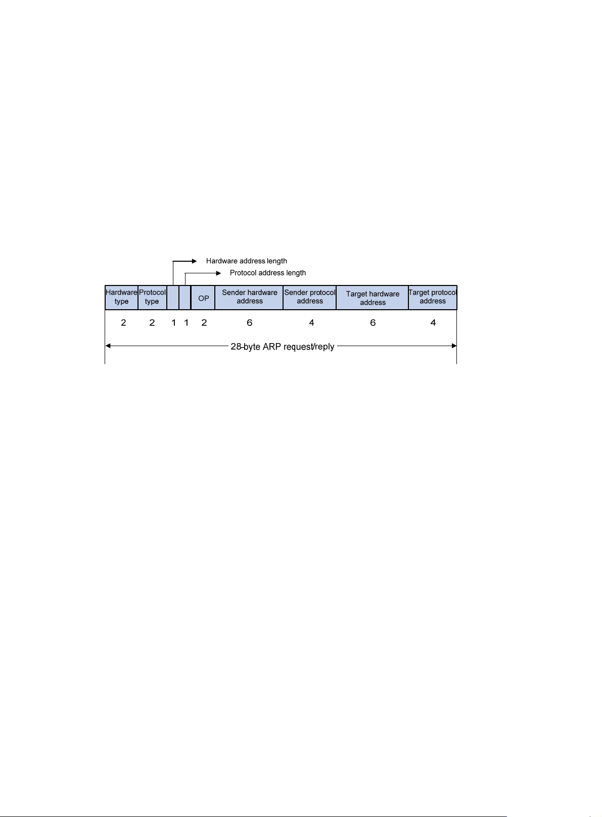
Configuring ARP
Overview
ARP resolves IP addresses into MAC addresses on Ethernet networks.
ARP message format
ARP uses two types of messages: ARP request and ARP reply. Figure 1 shows the format of ARP
request/reply messages. Numbers in the figure refer to field lengths.
Figure 1 ARP message format
• Hardware type—Hardware address type. The value 1 represents Ethernet.
• Protocol type—Type of the protocol address to be mapped. The hexadecimal value 0x0800
represents IP.
• Hardware address length and protocol address length— Length, in bytes, of a hardware
address and a protocol address. For an Ethernet address, the value of the hardware address
length field is 6. For an IPv4 address, the value of the protocol address length field is 4.
• OP—Operation code, which describes the type of ARP message. The value 1 represents an
ARP request, and the value 2 represents an ARP reply.
• Sender hardware address—Hardware address of the device sending the message.
• Sender protocol address—Protocol address of the device sendin g the message.
• Target hardware address—Hardware address of the device to which the message is being
sent.
• Target protocol address—Protocol address of the device to which the messag e is being sent.
ARP operating mechanism
As shown in Figure 2, Host A and Host B are on the same subnet. Host A sends a packet to Host B as
follows:
1. Host A looks through the ARP table for an ARP entry for Host B. If one entry is found, Host A
uses the MAC address in the entry to encapsulate the IP packet into a data link layer frame.
Then Host A sends the frame to Host B.
2. If Host A finds no entry for Host B, Host A buffers the packet and broadcasts an ARP request.
The payload of the ARP request contains the following information:
{ Sender IP address and sender MAC address—Host A's IP address and MAC address.
{ Target IP address—Host B's IP address.
{ Target MAC address—An all-zero MAC address.
1
Page 15
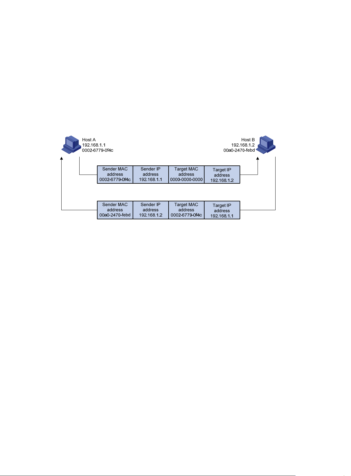
All hosts on this subnet can receive the broadcast request, but only the requested host (Host B)
processes the request.
3. Host B compares its own IP address with the target IP address in the ARP request. If they are
the same, Host B operates as follows:
a. Adds the sender IP address and sender MAC address into its ARP table.
b. Encapsulates its MAC add ress into an ARP reply.
c. Unicasts the ARP reply to Host A.
4. After receiving the ARP reply, Host A operates as follows:
a. Adds the MAC address of Host B into its ARP table.
b. Encapsulates the MAC add ress into the packet and sends the packet to Host B.
Figure 2 ARP address resolution process
If Host A and Host B are on different subnets, Host A sends a packet to Host B as follows:
5. Host A broadcasts an ARP request where the target IP address is the IP address of the
gateway.
6. The gateway responds with its MAC address in an ARP reply to Host A.
7. Host A uses the gateway's MAC address to encapsulate the packet, and then sen ds the packet
to the gateway.
8. If the gateway has an ARP entry for Host B, it forwards the packet to Host B directly. If not, the
gateway broadcasts an ARP request, in which the target IP address is the IP address of Host B.
9. After the gateway gets the MAC address of Host B, it sends the packet to Host B.
ARP table
An ARP table stores dynamic, static, OpenFlow, and Rule ARP entries.
Dynamic ARP entry
ARP automatically creates and updates dynamic entries. A dynamic ARP entry is removed when its
aging timer expires or the output interface goes down. In addition, a dynamic ARP entry can be
overwritten by a static ARP entry.
Static ARP entry
A static ARP entry is manually configured and maintained. It does not age out and cannot be
overwritten by any dynamic ARP entry.
Static ARP entries protect communication between devices because attack packets cannot modify
the IP-to-MAC mapping in a static ARP entry.
A static ARP entry contains only the IP address and MAC address.
2
Page 16

• If the output interface is a Layer 3 Ethernet interface, the ARP entry can be directly used to
forward packets.
• If the output interface is a VLAN interface, the device sends an ARP request whose target IP
address is the IP address in the entry . If the sender IP and MAC addresses in the received ARP
reply match the static ARP entry, the device performs the following operations:
{ Adds the interface that received the ARP reply to the static ARP entry.
{ Uses the resolved static A RP entry to forward IP packets.
T o communicate with a ho st by using a fixed IP-to-MAC mapping, configure a static ARP entry on the
device.
OpenFlow ARP entry
ARP creates OpenFlow ARP entries by learning from the OpenFlow module. An OpenFlow ARP
entry does not age out, and it cannot be updated. It can be overwritten by a static ARP entry. An
OpenFlow ARP entry can be used directly to forwar d packets. For more information about Op enFlow ,
see OpenFlow Configuration Guide.
Rule ARP entry
ARP creates Rule ARP entries by learning from the IPoE, portal, and VXLAN modules. A Rule ARP
entry does not age out, and it cannot be updated. It can be overwritten by a static ARP entry. A Rule
ARP entry can be used directly to forward packets.
For more information about IPoE, see Layer 2—WAN Access Configuration Guide. For more
information about portal, see Security Configuration Guide. For more information about VXLAN, see
VXLAN Configuration Guide.
Configuring a static ARP entry
Static ARP entries are effective when the device functions correctly.
To configure a static ARP entry:
Step Command Remarks
1. Enter system view.
2. Configure a static ARP
entry.
system-view
arp static
vpn-instance
[
ip-address mac-address
vpn-instance-name ]
N/A
By default, no static ARP entries
exist.
Setting the maximum number of dynamic ARP entries for a device
A device can dynamically learn ARP entries. To prevent a device from holding too many ARP entries,
you can set the maximum number of dynamic ARP entries that the device can learn. When the
maximum number is reached, the device stops learning ARP entries.
If you set a value lower than the number of existing dynamic ARP entries, the device does not
remove the existing entries unless they are aged out.
To set the maximum number of dynamic ARP entries for a device:
Step Command Remarks
1. Enter system view.
system-view
N/A
3
Page 17

Step Command Remarks
By default, the maximum
number of dynamic ARP entries
that a device can learn is the
upper limit of the allowed value
range.
To disable the device from
learning dynamic ARP entries,
set the number to 0.
2. Set the maximum
number of dynamic
ARP entries for the
device.
• In standalone mode:
arp max-learning-number
max-number slot slot-number
• In IRF mode:
arp max-learning-number
max-number chassis chassis-number
slot slot-number
Setting the maximum number of dynamic ARP entries for an interface
An interface can dynamically learn ARP entries. To prevent an interface from holding too many ARP
entries, you can set the maximum number of dynamic ARP entries that the interface can learn. When
the maximum number is reached, the interface stops learning ARP entries.
You can set limits for both a Layer 2 interface and the VLAN interface for a permitted VLAN on the
Layer 2 interface. The Layer 2 interface learns an ARP entry only when neither limit is reached.
The total number of dynamic ARP entries that all interfaces learn will not be larger than the maximum
number of dynamic A RP entries set for the device.
To set the maximum number of dynamic ARP entries for an interface:
Step Command Remarks
1. Enter system view.
2. Enter interface view.
3. Set the maximum number
of dynamic ARP entries for
the interface.
system-view
interface
interface-number
arp max-learning-num
max-number
interface-type
N/A
N/A
By default, the maximum number of
dynamic ARP entries that an interface
can learn is the upper limit of the
allowed value range.
To disable the interface from learning
dynamic ARP entries, set the number
to 0.
Setting the aging timer for dynamic ARP entries
Each dynamic ARP entry in the ARP table has a limited lifetime, called an aging timer. The aging
timer of a dynamic ARP entry is reset each time the dynamic ARP entry is updated. A dynamic ARP
entry that is not updated before its aging timer expires is deleted from the ARP table.
To set the aging timer for dynamic ARP entrie s:
Step Command Remarks
1. Enter system view.
2. Set the aging timer for dynamic
ARP entries.
system-view
arp timer aging
4
N/A
aging-time The default setting is 20 minutes.
Page 18
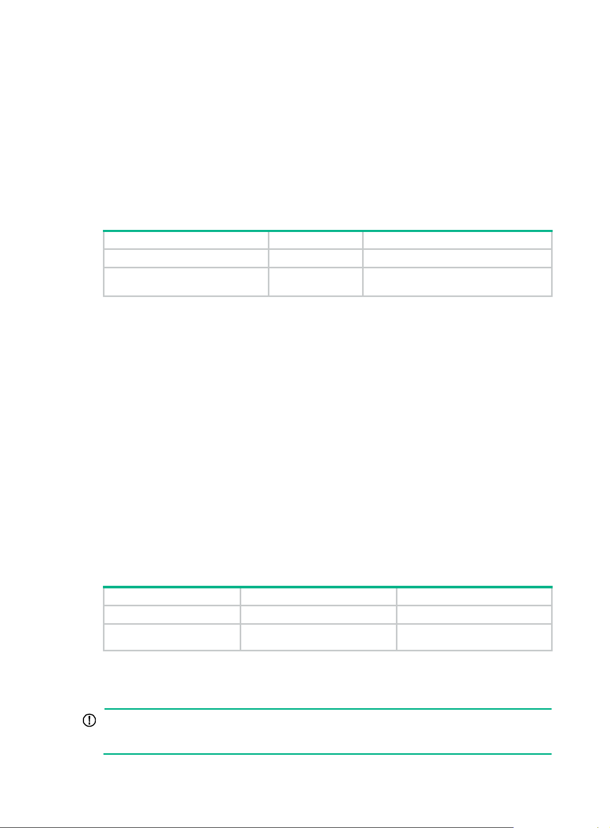
Enabling dynamic ARP entry check
The dynamic ARP entry check feature disables the de vice from supporting dynamic ARP entries that
contain multicast MAC addresses. The device cannot learn dynamic ARP entries containing
multicast MAC addresses. You cannot manually add static ARP entries containing multicast MAC
addresses.
When dynamic ARP entry check is disabled, ARP entries containing multicast MAC addresses are
supported. The device can learn dynamic ARP entries containing multicast MAC addresses obtained
from the ARP packets sourced from a unicast MAC address. You can also manually add static ARP
entries containing multicast MAC addresses.
To enable dynamic ARP entry check:
Step Command Remarks
1. Enter system view.
2. Enable dynamic ARP entry
check.
system-view
arp check enable
N/A
By default, dynamic ARP entry check is
enabled.
Enabling ARP logging
This feature enables a device to log ARP events when ARP cannot resolve IP addresses correctly.
The device can log the following ARP events:
• On a proxy ARP-disabled interface, the target IP address of a received ARP packet is not one of
the following IP addresses:
{ The IP address of the receiving interface.
{ The virtual IP address of the VRRP group.
{ The public IP address after NAT.
• The sender IP address of a received ARP reply conflicts with on e of the following IP addresses:
{ The IP address of the receiving interface.
{ The virtual IP address of the VRRP group.
{ The public IP address after NAT.
The device sends ARP log messages to the informatio n center . You can use the info-center source
command to specify the log output rules for the information center. For more information about
information center, see Network Management and Monitoring Configuration Guide.
To enable the ARP logging feature:
Step Command Remarks
1. Enter system view.
2. Enable the ARP logging
feature.
system-view
arp check log enable
N/A
By default, ARP logging is disabled.
Displaying and maintaining ARP
IMPORTANT:
Clearing ARP entries from the ARP table might cause communication failures. Make sure the entries
to be cleared do not affect current communications.
5
Page 19
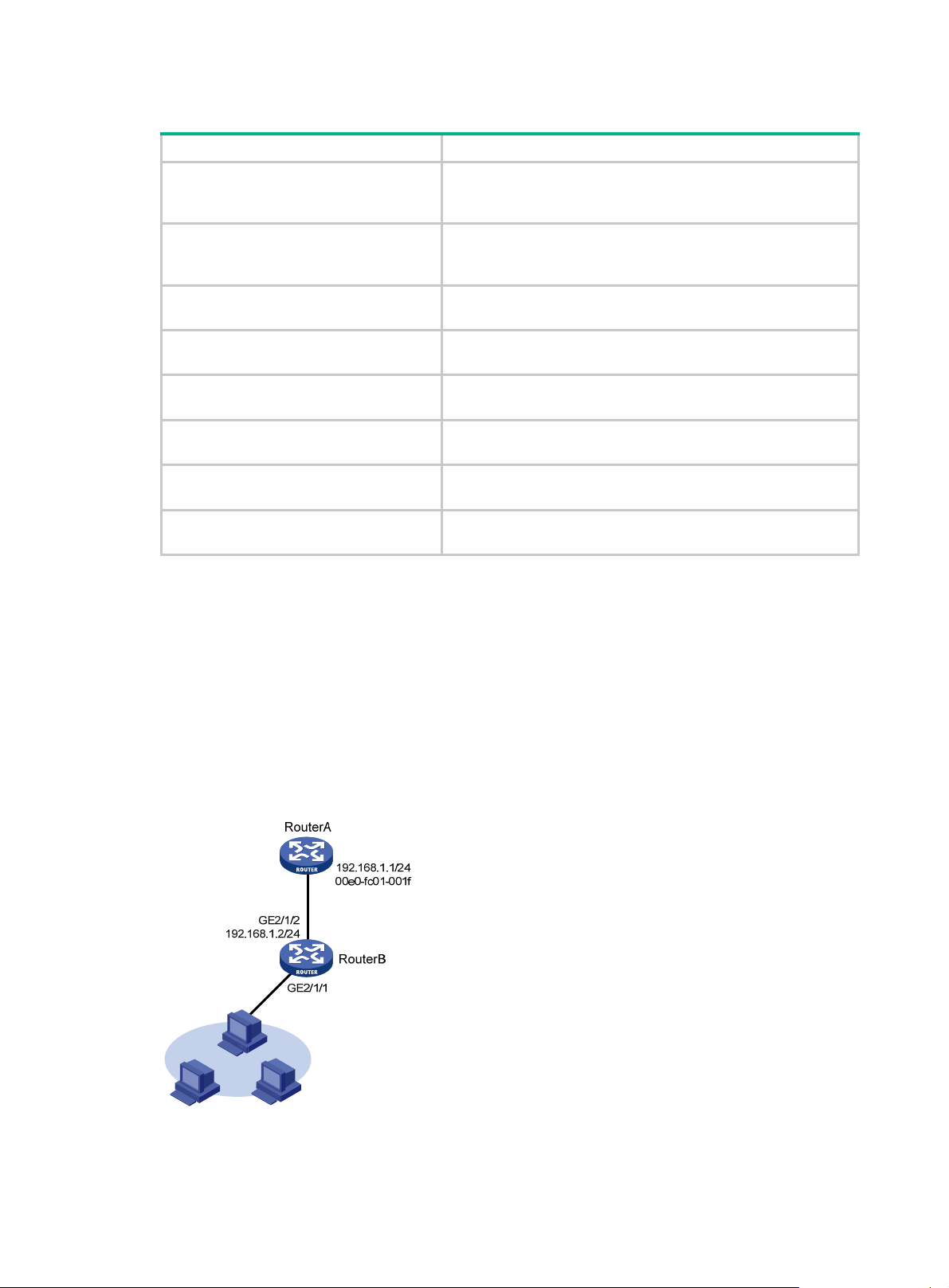
Execute display commands in any view and reset commands in user view.
Task Command
Display ARP entries (in standalone
mode).
display arp
vlan-id |
verbose ]
all
[ [
interface
dynamic
|
interface-type interface-number ] [
static
|
] [
slot
slot-number ] |
count
vlan
|
Display ARP entries (in IRF mode).
Display the ARP entry for an IP address
(in standalone mode).
Display the ARP entry for an IP address
(in IRF mode).
Display the ARP entries for a VPN
instance.
Display the aging timer of dynamic ARP
entries.
Clear ARP entries from the ARP table (in
standalone mode).
Clear ARP entries from the ARP table (in
IRF mode).
display arp
slot
slot-number ] |
interface-number ] [
display arp
display arp
slot-number ] [
display arp vpn-instance
display arp timer aging
reset arp
interface-number |
reset arp
dynamic
all
[ [
|
ip-address [
ip-address [
verbose ]
all
dynamic
{
|
all
chassis
{
|
interface
|
dynamic | static
vlan
vlan-id |
count
slot
interface-type interface-number |
verbose ]
|
slot
slot-number ] [
chassis
vpn-instance-name [
interface
|
slot-number |
chassis-number
chassis
] [
interface
chassis-number
interface-type
static }
Static ARP entry configuration example
Network requirements
chassis-number
interface-type
verbose ]
slot
count ]
slot
slot-number |
static }
As shown in Figure 3, hosts are connected to Router B. Router B is connected to Router A through
interface GigabitEthernet 2/1/2.
To ensure secure communications between Router B and Router A, configure a static ARP entry for
Router A on Router B.
Figure 3 Network diagram
6
Page 20

Configuration procedure
# Configure an IP address for GigabitEthernet 2/1/2.
<RouterB> system-view
[RouterB] interface gigabitethernet 2/1/2
[RouterB-GigabitEthernet2/1/2] ip address 192.168.1.2 24
[RouterB-GigabitEthernet2/1/2] quit
# Configure a static ARP entry that has IP address 192.168.1.1 and MAC address 00e0-fc01-001f.
[RouterB] arp static 192.168.1.1 00e0-fc01-001f
Verifying the configuration
# Verify that Router B has a static ARP entry for Router A.
[RouterB] display arp static
Type: S-Static D-Dynamic O-Openflow R-Rule M-Multiport I-Invalid
IP address MAC address SVID Interface Aging Type
192.168.1.1 00e0-fc01-001f -- -- -- S
7
Page 21

Configuring gratuitous ARP
Overview
In a gratuitous ARP packet, the sender IP address and the target IP address are the IP address of
the sending device.
A device sends a gratuitous ARP packet for either of the following purposes:
• Determine whether its IP address is already used by another device. If the IP address is already
used, the device is informed of the conflict by an ARP reply.
• Inform other devices of a MAC address change.
Gratuitous ARP packet learning
This feature enables a device to create or update ARP entries by using the sender IP and MAC
addresses in received gratuitous ARP packets.
When this feature is disabled, the device uses received gratuitous ARP packets to update existing
ARP entries only. ARP entries are not created based on the received gratuitous ARP packets, which
saves ARP table space.
Periodic sending of gratuitous ARP packets
Enabling periodic sending of gratuitous ARP packets help s downstream devices update ARP entries
or MAC entries in a timely manner.
This feature can implement the following functions:
• Prevent gateway spoofing.
Gateway spoofing occurs when an attacker uses the gateway address to send gratuitous ARP
packets to the hosts on a network. The traffic destined for the gateway from the hosts is sent to
the attacker instead. As a result, the hosts cannot access the external network.
To prevent such gateway spoofing attacks, you can enable the gateway to send gratuitous ARP
packets at intervals. Gratuitous ARP packets contain the primary IP address and manually
configured secondary IP addresses of the gateway, so hosts can learn correct gateway
information.
• Prevent ARP entries from aging out.
If network traffic is heavy or if the host CPU usage is high, received ARP packets can be
discarded or are not promptly processed. Eventually, the dynamic ARP entries on the receiving
host age out. The traffic between the host and the corresponding d evices is interrupted until the
host re-creates the ARP entries.
To prevent this problem, you can enable the gateway to send gratuitous ARP packets
periodically. Gratuitous ARP packets contain the primary IP address and manually configured
secondary IP addresses of the gateway, so the receiving hosts can update ARP entries in a
timely manner.
• Prevent the virtual IP address of a VRRP group from being used by a host.
The master router of a VRRP group can periodically send gratuitous ARP packets to the hosts
on the local network. The hosts can then update local ARP entries and avoid using the virtual IP
address of the VRRP group. The sender MAC address in the gratuitous ARP packet is the
virtual MAC address of the virtual router. For more information about VRRP, see High
Availability Configuration Guide.
8
Page 22

• Update MAC entries of devices in the VLANs having ambiguous Dot1q or QinQ termination
configured.
In VRRP configuration, if ambiguous Dot1q or QinQ termination is configured for multiple
VLANs and VRRP groups, interfaces configured with VLAN termination must be disabled from
transmitting broadcast/multicast packets. Also, a VRRP control VLAN must be configured so
that VRRP advertisements can be transmitted within the control VLAN only. In such cases, you
can enable periodic sending of gratuitous ARP packets containing the following addresses:
{ The VRRP virtual IP address.
{ The primary IP address or a manually configured secondary IP address of the sending
interface on the subinterfaces.
When a VRRP f a il ov er o cc urs, d ev i ces in the VLANs can use the gratuito u s ARP packets to update
their corresponding MAC entries in a timely manner. For more information about ambiguous Dot1q
or QinQ termination, see Layer 2—LAN Switching Configuration Guide.
Configuration procedure
When you configure gratuitous ARP, follow these restrictions and guidelines:
• You can enable periodic sending of gratuitous ARP packets on a maximum of 1024 interfaces.
• Periodic sending of gratuitous ARP packets takes ef fect on an interface only when the following
conditions are met:
{ The data link layer state of the interface is up.
{ The interface has an IP address.
• If you change the sending interval for gratuitous ARP packets, the configuration takes ef fect at
the next sending interval.
• The sending interval for gratuitous ARP packets might be much longer than the specified
sending interval in any of the following circumstances:
{ This feature is enabled on multiple interfaces.
{ Each interface is configured with multiple secondary IP addresses.
{ A small sending interval is configured when the previous two conditions exist.
To configure gratuitous ARP:
Step Command Remarks
1. Enter system view.
2. Enable learning of gratuitous
ARP packets.
3. Enable the device to send
gratuitous ARP packets upon
receiving ARP requests
whose sender IP address
belongs to a different subnet.
4. Enter interface view.
5. Enable periodic sending of
gratuitous ARP packets.
system-view
gratuitous-arp-learning enable
gratuitous-arp-sending enable
interface
interface-number
arp send-gratuitous-arp
interval
[
interface-type
interval ]
9
N/A
By default, learning of gratuitous
ARP packets is enabled.
By default, a device does not send
gratuitous ARP packets upon
receiving ARP requests whose
sender IP address belongs to a
different subnet.
N/A
By default, periodic sending of
gratuitous ARP packets is
disabled.
Page 23

Enabling IP conflict notification
By default, if the sender IP address of an incoming ARP packet is the same a s that of the device, the
device sends a gratuitous A RP request. The device displays an error message only after it receives
an ARP reply about the conflict.
You can use this command to enable the device to display error messages before sending a
gratuitous ARP reply or request for conflict confirmation.
To enable IP conflict notification:
Step Command Remarks
1. Enter system view.
2. Enable IP conflict
notification.
system-view
arp ip-conflict log prompt
N/A
By default, IP conflict notification is
disabled.
10
Page 24

Configuring proxy ARP
Proxy ARP enables a device on one network to answer ARP requests for an IP address on another
network. With proxy ARP, hosts on different broadcast domains can communicate with each other as
they would on the same broadcast domain.
Proxy ARP includes common proxy ARP and local proxy ARP.
• Common proxy ARP—Allows communication between hosts that conne ct to diff erent Layer 3
interfaces and reside in different broadcast domains.
• Local proxy ARP—Allows communication between hosts that connect to the same Layer 3
interface and reside in different broadcast domains.
Enabling common proxy ARP
Step Command Remarks
1. Enter system view.
2. Enter interface view.
system-view
interface
interface-number
interface-type
N/A
The following interface types are
supported:
• Layer 3 Ethernet interface.
• Layer 3 Ethernet subinterface.
• Layer 3 aggregate interface.
• Layer 3 aggregate subinterface.
3. Enable common proxy ARP.
proxy-arp enable
Enabling local proxy ARP
Step Command Remarks
1. Enter system view.
2. Enter interface view.
3. Enable local proxy ARP.
system-view
interface
interface-number
local-proxy-arp enable
ip-range
[
end-ip-address ]
interface-type
start-ip-address to
Displaying proxy ARP
By default, common proxy ARP is
disabled.
N/A
The following interface types are
supported:
• Layer 3 Ethernet interface.
• Layer 3 Ethernet subinterface.
• Layer 3 aggregate interface.
• Layer 3 aggregate subinterface.
By default, local proxy ARP is
disabled.
Execute display commands in any view .
11
Page 25
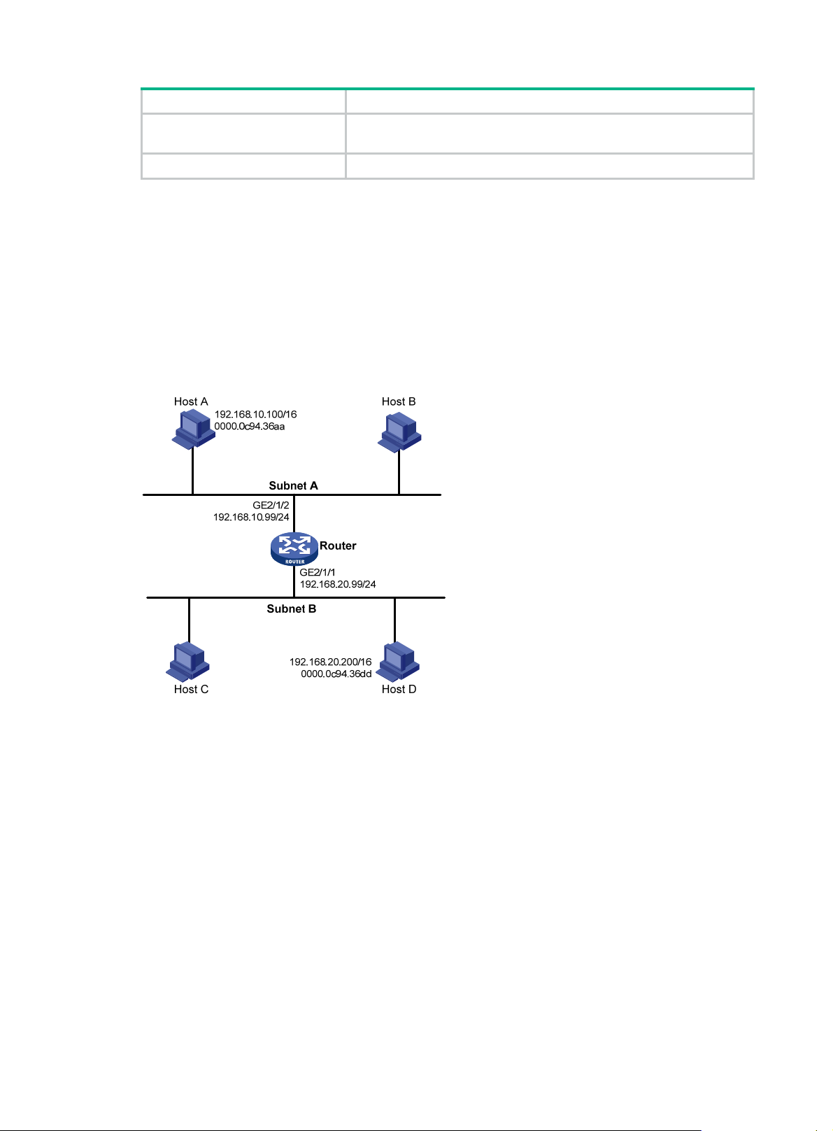
Task Command
Display common proxy ARP
status.
display proxy-arp [ interface
interface-type interface-number ]
Display local proxy ARP status.
display local-proxy-arp [ interface
interface-type interface-number ]
Common proxy ARP configuration example
Network requirements
As shown in Figure 4, Host A and Host D have the same prefix and mask, but they are located on
different subnets. No default gateway is configured on Host A and Host D.
Configure common proxy ARP on the router to enable communication between Host A and Host D.
Figure 4 Network diagram
Configuration procedure
# Configure the IP address of interface GigabitEthernet 2/1/2.
<Router> system-view
[Router] interface gigabitethernet 2/1/2
[Router-GigabitEthernet2/1/2] ip address 192.168.10.99 255.255.255.0
# Enable common proxy ARP on interface GigabitEthernet 2/1/2.
[Router-GigabitEthernet2/1/2] proxy-arp enable
[Router-GigabitEthernet2/1/2] quit
# Configure the IP address of interface GigabitEthernet 2/1/1.
[Router] interface gigabitethernet 2/1/1
[Router-GigabitEthernet2/1/1] ip address 192.168.20.99 255.255.255.0
# Enable common proxy ARP on interface GigabitEthernet 2/1/1.
[Router-GigabitEthernet2/1/1] proxy-arp enable
12
Page 26

[Router-GigabitEthernet2/1/1] quit
Verifying the configuration
# Verify that Host A and Host D can ping each other.
13
Page 27
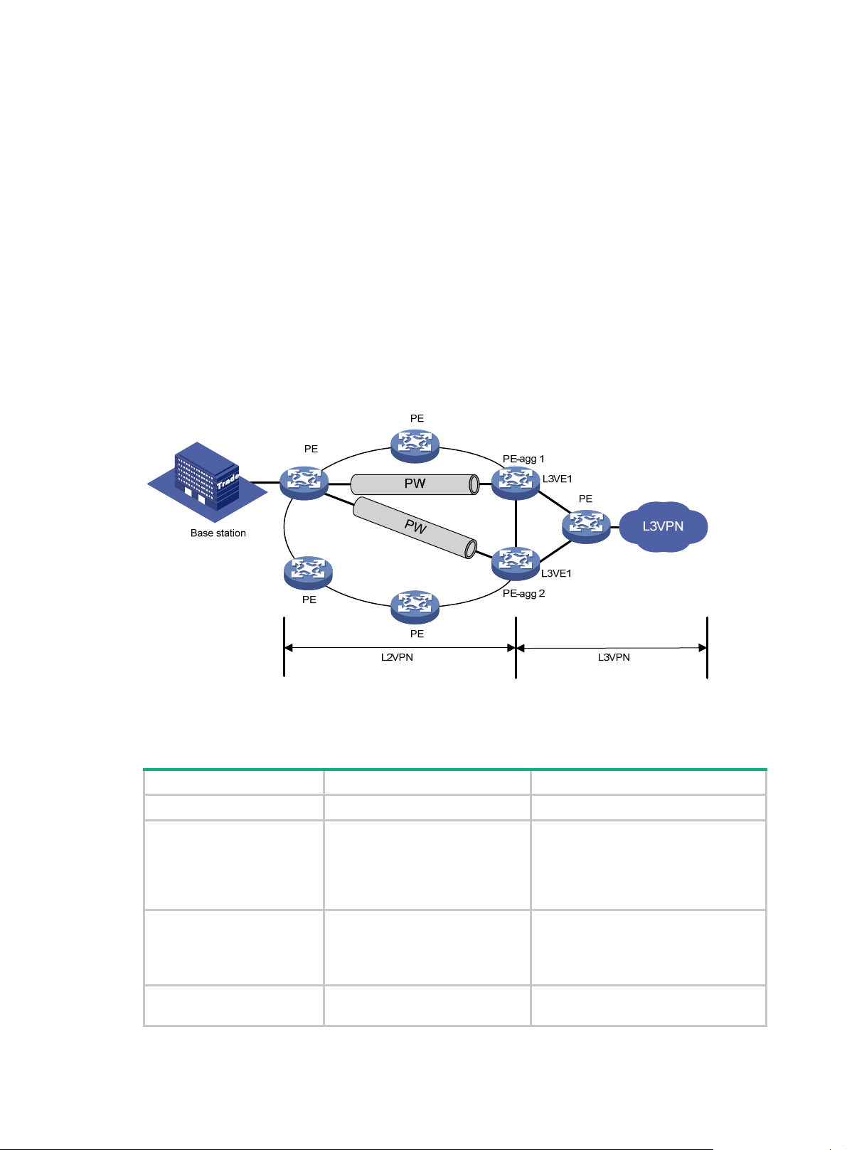
Configuring ARP suppression
Overview
The ARP suppression feature enables a device to directly answer ARP requests by using ARP
suppression entries. The device generates ARP suppression entrie s based on dy namic ARP entries
that it learns. This feature is typically configured on the PEs connected to base stations in an MPLS
L2VPN that provides access to an L3VPN network.
You can also configure the ARP suppression push feature to push ARP suppression entries by
broadcasting gratuitous ARP packets.
Figure 5 s
to the base station. The PE generates ARP suppression entries for the base station, PE-agg 1, and
PE-agg 2, and it directly replies subsequent ARP requests for these devices.
Figure 5 Typical application
hows a typical application scenario. ARP suppression is enabled on the PE that connects
Configuration procedure
Step Command Remarks
1. Enter system view.
2. Create a cross-connect
group and enter its view.
3. Create a cross-connect
and enter its view.
4. Enable ARP
suppression.
system-view
xconnect-group
connection
arp suppression enable
N/A
group-name
connection-name
14
By default, no cross-connect groups
exist.
For more information about this
command, see MPLS Command
Reference.
By default, no cross-connects exist.
For more information about this
command, see MPLS Command
Reference.
By default, ARP suppression is
disabled.
Page 28
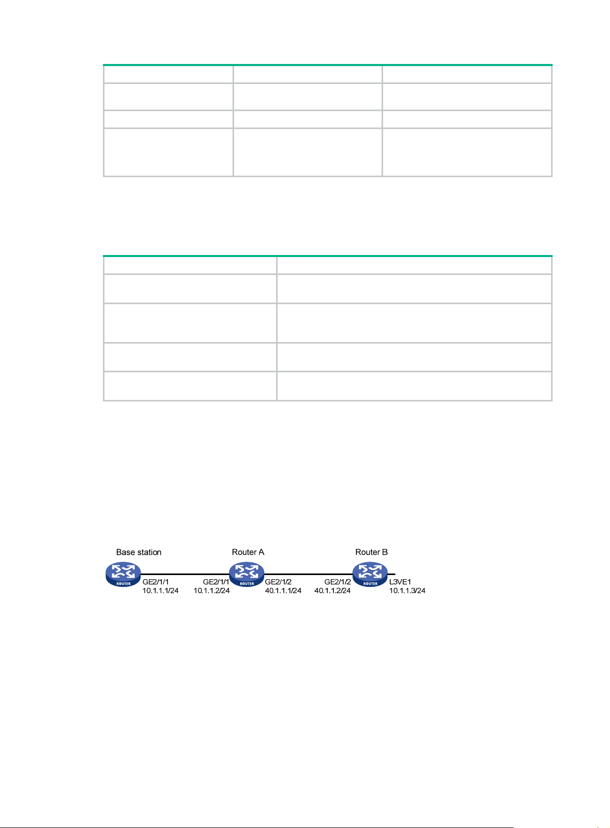
Step Command Remarks
5. Return to cross-connect
group view.
6. Return to system view.
7. (Optional.) Enable the
ARP suppression push
feature and set a push
interval.
quit
quit
arp suppression push interval
interval
N/A
N/A
By default, the ARP suppression push
feature is disabled.
Displaying and maintaining ARP suppression
Execute display commands in any view and reset commands in user view.
Task Command
Display ARP suppression entries (in
standalone mode).
display arp suppression xconnect-group
group-name ] [
slot
slot-number ] [
count ]
name
[
Display ARP suppression entries (in
IRF mode).
Clear dynamic ARP suppression entries
(in standalone mode).
Clear dynamic ARP suppression entries
(in IRF mode).
display arp suppression xconnect-group
group-name ] [
count ]
[
reset arp suppression xconnect-group
slot
[
slot-number ]
reset arp suppression xconnect-group
chassis
[
chassis
chassis-number
chassis-number
slot
slot-number ]
slot
[
[
ARP suppression configuration example
Network requirements
As shown in Figure 6, the base station, Router A, and Router B are in an MPLS L2VPN.
Enable ARP suppression on Router A to directly reply to ARP requests for Router B.
Figure 6 Network diagram
name
[
slot-number ]
name
group-name ]
name
group-name ]
Configuration procedure
1. Configure IP addresses for the interfaces, and make sure the base station can reach the L3VE
interface VE-L3VPN 1 of Router B. (Details not shown.)
2. Configure ARP suppression on Router A:
# Create a cross-connect group named vpna and create a cross-connect named svc in the
group.
<RouterA> system-view
[RouterA] xconnect-group vpna
15
Page 29

[RouterA-xcg-vpna] connection svc
# Enable ARP suppression for the cross-connect svc in cross-connect group vpna.
[RouterA-xcg-vpna-svc] arp suppression enable
Verifying the configuration
1. On the base station, clear ARP entries, and ping the L3VE interface VE-L3VPN 1 of Router B.
(Details not shown.)
2. Verify that Router A has ARP suppression entries for the base station and Router B.
[RouterA-xcg-vpna-svc] display arp suppression xconnect-group
IP address MAC address Xconnect-group Connection Aging
10.1.1.1 00e0-fc04-582c vpna svc 25
10.1.1.3 0023-89b7-0861 vpna svc 25
3. Enable ARP debugging on Router B to verify that Router B does not receive an ARP request
from the base station under the following conditions (details not shown):
a. Clear ARP entries on the base station.
b. Ping the L3VE interface VE-L3VPN 1 of Router B from the base station.
16
Page 30
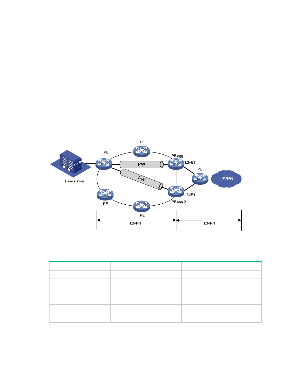
Configuring ARP direct route advertisement
Overview
The ARP direct route advertisement feature advertises host route s instead of advertising the network
route. This feature is typically configured on PE-aggs to advertise host routes to the connected PEs
in the L3VPN.
Figure 7 sho
to a base station in the L2VPN. Traffic from the PE in the L3VPN to the base station can be load
shared by PE-agg 1 and PE-agg 2. If PE-agg 1 fails, the PE uses the host route through PE-agg 2 to
forward traffic.
Figure 7 Typical application
ws a typical application scenario where the PE in the L3VPN has ECMP routes destined
Configuration procedure
Step Command Remarks
1. Enter system view.
2. Create an L3VE
interface and enter its
view.
3. Enable the ARP direct
route advertisement
feature.
system-view
interface ve-l3vpn
interface-number
arp route-direct advertise
N/A
17
By default, no L3VE interface exists.
For more information about this
command, see MPLS Command
Reference.
By default, the ARP direct route
advertisement feature is disabled.
Page 31

Configuring IP addressing
The IP addresses in this chapter refer to IPv4 addresses unless otherwise specified.
This chapter describes IP addressing basics and manual IP address assignment for interfaces.
Dynamic IP address assignment (BOOTP and DHCP) and PPP address negotiation are bey ond the
scope of this chapter.
Overview
This section describes the IP addressing basics.
IP addressing uses a 32-bit address to identify each host on an IPv4 network. To make addresses
easier to read, they are written in dotted decimal notation, each address being four octets in length.
For example, address 00001010000000010000000100000001 in binary is written as 10.1.1.1.
IP address classes
Each IP address breaks down into the following sections:
• Net ID—Identifies a network. The first several bits of a net ID, known as the class field or class
bits, identify the class of the IP address.
• Host ID—Identifies a host on a network.
IP addresses are divided into five classes, as shown in Figure 8.
address class. The first three classes are most commonly used.
Figure 8 IP address classes
Table 1 IP address classes and ranges
Class Address range Remarks
The IP address 0.0.0.0 is used by a host at startup for
temporary communication. This address is never a
valid destination address.
A 0.0.0.0 to 127.255.255.255
Addresses starting with 127 are reserved for loopback
test. Packets destined to these addresses are
processed locally as input packets rather than sent to
the link.
The shaded areas represent the
B 128.0.0.0 to 191.255.255.255 N/A
C 192.0.0.0 to 223.255.255.255 N/A
D 224.0.0.0 to 239.255.255.255 Multicast addresses.
18
Page 32

Class Address range Remarks
E 240.0.0.0 to 255.255.255.255
Special IP addresses
The following IP addresses are for special use and cannot be used as ho st IP addresses:
• IP address with an all-zero net ID—Identifies a host on the local network. For example, IP
address 0.0.0.16 indicates the host with a host ID of 16 on the local network.
• IP address with an all-zero host ID—Identifies a network.
• IP address with an all-one host ID—Identifies a directed broadcast address. For example, a
packet with the destination address of 192.168.1.255 will be broadcast to all the hosts on the
network 192.168.1.0.
Subnetting and masking
Subnetting divides a network into smaller networks called subnet s by using som e bits of the h ost ID
to create a subnet ID.
Masking identifies the boundary between the host ID and the combination of net ID and subnet ID.
Reserved for future use, except for the broadcast
address 255.255.255.255.
Each subnet mask comprises 32 bits that corre spond to the bits i n an IP address. In a subnet mask,
consecutive ones represent the net ID and subnet ID, and consecutive zeros represent the host ID.
Before being subnetted, Class A, B, and C networks use these default masks (also called natural
masks): 255.0.0.0, 255.255.0.0, and 255.255.255.0, respectively.
Figure 9 Subnetting a Class B network
Subnetting increases the number of addresses that cannot be assigned to hosts. Therefore, using
subnets means accommodating fewer hosts.
For example, a Class B network without subnetting can accommodate 1022 more hosts than the
same network subnetted into 512 subnets.
16
• Without subnetting—65534 (2
address, which has an all-one host ID, and the network address, which has an all-zero host ID.)
• With subnetting—Using the first nine bits of the host-id for subnetting provides 512 (2
subnets. However, only sev en bits remain available for the host ID. This allows 126 (2
hosts in each subnet, a total of 64512 (512 × 126) hosts.
– 2) hosts. (The two deducted addresses are the broadcast
9
)
7
– 2)
Assigning an IP address to an interface
An interface must have an IP address to communicate with other hosts. You can either manually
assign an IP address to an interface, or configure the interface to obtain an IP address through
BOOTP, DHCP, or PPP address negotiation. If you change the IP address assignment method, the
new IP address will overwrite the previous address.
19
Page 33

An interface can have one primary address and multiple secondary addresses.
Typically, you need to configure a primary IP address for an interface. If the interface connects to
multiple subnets, configure primary and secondary IP addresses on the interface so the subnets can
communicate with each other through the interface.
Configuration guidelines
Follow these guidelines when you assign an IP address to an interface:
• An interface can have only one primary IP address. A newly configured primary IP address
overwrites the previous one.
• You cannot assign secondary IP addresses to an interface that obtains an IP address through
BOOTP, DHCP, PPP address negotiation, or IP unnumbered.
• The primary and secondary IP addresses assigned to the interfa ce can be located on the same
network segment. Different interfaces on your device must reside on different network
segments.
Configuration procedure
To assign an IP address to an interface:
Step Command Remarks
1. Enter system view.
2. Enter interface view.
3. Assign an IP address to the
interface.
system-view
interface
interface-number
ip address
mask-length } [
interface-type
ip-address { mask |
sub
Configuring IP unnumbered
Typically, you assign an IP address to an interface either manually or through DHCP. If the IP
addresses are not enough, or the interface is used only occasionally, you can configure an interface
to borrow an IP address from other interfaces. This is called IP unnumbered, and the interface
borrowing the IP address is called IP unnumbered interface.
You can use IP unnumbered to save IP addresses either when available IP addresses are
inadequate or when an interface is brought up only for occasional use.
Configuration guidelines
Follow these guidelines when you configure IP unnum bered:
• Loopback interfaces cannot borrow IP addresses of other interfaces, but other interfaces can
borrow IP addresses of loopback interfaces.
• An interface cannot borrow an IP address from an unnumbered interface.
• Multiple interfaces can use the same unnumbered IP address.
• If an interface has multiple manually configured IP addresses, only the manually configured
primary IP address can be borrowed.
N/A
N/A
By default, no IP address is
]
assigned to the interface.
20
Page 34

Configuration prerequisites
Assign an IP address to the interface from which you want to borrow the IP address. Alternatively,
you can configure the interface to obtain one through BOOTP, DHCP, or PPP address negotiation.
Configuration procedure
To configure IP unnumbered on an interface:
Step Command Remarks
1. Enter system view.
system-view
N/A
2. Enter interface view.
3. Specify the interface to borrow
the IP address of the specified
interface.
A dynamic routing proto col cannot be enabled on the interface where IP unnumbered is configured.
T o enable the interface to communicate with other devices, configure a static route to the peer device
on the interface. For more configuration information, see "IP unnumbered co nfiguration example."
interface
interface-number
ip address unnumbered
interface
interface-number
interface-type
interface-type
N/A
By default, the interface does
not borrow IP addresses from
other interfaces.
Displaying and maintaining IP addressing
Execute display commands in any view .
Task Command
Display IP configuration and statistics for the
specified or all Layer 3 interfaces.
Display brief IP configuration for Layer 3 interfaces.
display ip interface
interface-number ]
display ip interface
[ interface-number ] ]
[ interface-type
[ interface-type
brief [ description
Configuration examples
]
IP address configuration example
Network requirements
As shown in Figure 10, GigabitEthernet 2/1/1 on the router is connected to a LAN comprising two
segments: 172.16.1.0/24 and 172.16.2.0/24.
To enable the hosts on the two network segments to communicate with the external network through
the router, and to enable th e hosts on the LAN to communicate with each other:
• Assign a primary IP address and a secondary IP address to GigabitEthernet 1/1 on the router.
• Set the primary IP address of the router as the gateway address of the PCs on subnet
172.16.1.0/24. Set the secondary IP address of the router as the gateway address of the PCs
on subnet 172.16.2.0/24.
21
Page 35

Figure 10 Network diagram
Configuration procedure
# Assign a pri m ary IP address and a secondary IP address to GigabitEthernet 2/1/1.
<Router> system-view
[Router] interface gigabitethernet 2/1/1
[Router-GigabitEthernet2/1/1] ip address 172.16.1.1 255.255.255.0
[Router-GigabitEthernet2/1/1] ip address 172.16.2.1 255.255.255.0 sub
# Set the gateway address to 172.16.1.1 on the PCs attached to subnet 172.16.1.0/24, and to
172.16.2.1 on the PCs attached to subnet 172.16.2.0/24.
Verifying the configuration
# Verify the connectivity between a host on subnet 172.16.1.0/24 and the router.
<Router> ping 172.16.1.2
Ping 172.16.1.2 (172.16.1.2): 56 data bytes, press CTRL_C to break
56 bytes from 172.16.1.2: icmp_seq=0 ttl=128 time=7.000 ms
56 bytes from 172.16.1.2: icmp_seq=1 ttl=128 time=2.000 ms
56 bytes from 172.16.1.2: icmp_seq=2 ttl=128 time=1.000 ms
56 bytes from 172.16.1.2: icmp_seq=3 ttl=128 time=1.000 ms
56 bytes from 172.16.1.2: icmp_seq=4 ttl=128 time=2.000 ms
--- Ping statistics for 172.16.1.2 ---
5 packet(s) transmitted, 5 packet(s) received, 0.0% packet loss
round-trip min/avg/max/std-dev = 1.000/2.600/7.000/2.245 ms
# Verify the connectivity between a host on subnet 172.16.2.0/24 and the router.
<Router> ping 172.16.2.2
Ping 172.16.2.2 (172.16.2.2): 56 data bytes, press CTRL_C to break
56 bytes from 172.16.2.2: icmp_seq=0 ttl=128 time=2.000 ms
56 bytes from 172.16.2.2: icmp_seq=1 ttl=128 time=7.000 ms
56 bytes from 172.16.2.2: icmp_seq=2 ttl=128 time=1.000 ms
56 bytes from 172.16.2.2: icmp_seq=3 ttl=128 time=2.000 ms
56 bytes from 172.16.2.2: icmp_seq=4 ttl=128 time=1.000 ms
22
Page 36

--- Ping statistics for 172.16.2.2 ---
5 packet(s) transmitted, 5 packet(s) received, 0.0% packet loss
round-trip min/avg/max/std-dev = 1.000/2.600/7.000/2.245 ms
# Verify the connectivity between a host on subnet 172.16.1.0/24 and a host on subnet 172.16. 2.0/24.
The ping operation succeeds.
IP unnumbered configuration example
Network requirements
As shown in Figure 11, two routers on an intranet are connected to each other through serial
interfaces across a Digital Data Network. Each router connects to a LAN through an Ethernet
interface.
To save IP addresses, configure the serial interfaces to borrow IP addresses from the Ethernet
interfaces.
Figure 11 Network diagram
DDN
Ser3/1/1
GE2/1/1
172.16.10.1/24
Configuration procedure
1. Configure Router A:
# Assign a primary IP address to GigabitEthernet 2/1/1.
<RouterA> system-view
[RouterA] interface gigabitethernet 2/1/1
[RouterA-GigabitEthernet2/1/1] ip address 172.16.10.1 255.255.255.0
[RouterA-GigabitEthernet2/1/1] quit
# Configure Serial 3/1/1 to borrow an IP address from GigabitEthernet 2/1/1.
[RouterA] interface serial 3/1/1
[RouterA-Serial3/1/1] ip address unnumbered interface gigabitethernet 2/1/1
[RouterA-Serial3/1/1] quit
# Configure a static route to the subnet attached to Router B, specifying Serial 3/1/1 as the
outgoing interface.
[RouterA] ip route-static 172.16.20.0 255.255.255.0 serial 3/1/1
2. Configure Router B:
# Assign a primary IP address to GigabitEthernet 2/1/1.
<RouterB> system-view
[RouterB] interface gigabitethernet 2/1/1
[RouterB-GigabitEthernet2/1/1] ip address 172.16.20.1 255.255.255.0
[RouterB-GigabitEthernet2/1/1] quit
Ser3/1/1
Router BRouter A
GE2/1/1
172.16.20.1/24
23
Page 37

# Configure interface Serial 3/1/1 to borrow an IP address from GigabitEthernet 2/1/1.
[RouterB] interface serial 3/1/1
[RouterB-Serial3/1/1] ip address unnumbered interface gigabitethernet 2/1/1
[RouterB-Serial3/1/1] quit
# Configure a static route to the subnet attached to Router A, specifying Serial 3/1/1 as the
outgoing interface.
[RouterB] ip route-static 172.16.10.0 255.255.255.0 serial 3/1/1
Verifying the configuration
# Verify that a host attached to Router B can be pinged from Router A.
[RouterA] ping 172.16.20.2
Ping 172.16.20.2 (172.16.20.2): 56 data bytes, press CTRL_C to break
56 bytes from 172.16.20.2: icmp_seq=0 ttl=128 time=7.000 ms
56 bytes from 172.16.20.2: icmp_seq=1 ttl=128 time=2.000 ms
56 bytes from 172.16.20.2: icmp_seq=2 ttl=128 time=1.000 ms
56 bytes from 172.16.20.2: icmp_seq=3 ttl=128 time=1.000 ms
56 bytes from 172.16.20.2: icmp_seq=4 ttl=128 time=2.000 ms
--- Ping statistics for 172.16.20.2 ---
5 packet(s) transmitted, 5 packet(s) received, 0.0% packet loss
round-trip min/avg/max/std-dev = 1.000/2.600/7.000/2.245 ms
24
Page 38

DHCP overview
The Dynamic Host Configuration Protocol (DHCP) provides a framework to assign configuration
information to network devices.
Figure 12 sho
reside on the same subnet. The DHCP clients can also obtain configuration parameters from a
DHCP server on another subnet through a DHCP relay agent. For more information about the DHCP
relay agent, see "Configuring the DHCP relay agent."
Figure 12 A typical DHCP application
ws a typical DHCP application scenario where the DHCP clients and the DHCP server
DHCP address allocation
Allocation mechanisms
DHCP supports the following allocation mechanisms:
• Static allocation—The network administrator assigns an IP address to a client, such as a
WWW server, and DHCP conveys the assigned address to the client.
• Automatic allocation—DHCP assigns a permanent IP address to a client.
• Dynamic allocation—DHCP assigns an IP address to a client for a limited period of time,
which is called a lease. Most DHCP clients obtain their addresses in this way.
25
Page 39

IP address allocation process
Figure 13 IP address allocation process
As shown in Figure 13, a DHCP server assigns an IP address to a DHCP client in the following
process:
1. The client broadcasts a DHCP-DISCOVER message to locate a DHCP server.
2. Each DHCP server offers configuration parameters such as an IP address to the client in a
DHCP-OFFER message. The sending mode of the DHCP-OFFER is determined by the flag
field in the DHCP-DISCOVER message. For more information, see "DHCP message format."
3. If the client receives multiple offers, it accepts the first received offer, and broadcasts it in a
DHCP-REQUEST message to formally request the IP address. (IP addresses offered by other
DHCP servers can be assigned to other clients.)
4. All DHCP servers receive the DHCP-REQUEST message. However, only the server sele cted
by the client does one of the following operations:
{ Returns a DHCP-ACK message to confirm that the IP address has been allocated to the
client.
{ Returns a DHCP-NAK message to deny the IP address allocation.
After receiving the DHCP-ACK message, the client verifies the following details before using the
assigned IP address:
• The assigned IP address is not in use. To verify this, the client broadcasts a gratuitous ARP
packet. The assigned IP address is not in use if no response is received within the specified
time.
• The assigned IP address is not on the same subnet as any IP address in use o n the clie nt.
Otherwise, the client sends a DHCP-DECLINE message to the server to request an IP address
again.
IP address lease extension
A dynamically assigned IP address has a lease. When the lease expires, the IP address is reclaimed
by the DHCP server. To continue using the IP address, the client must extend the lease duration.
When about half of the lease duration elapses, the DHCP client unicasts a DHCP-REQUEST to the
DHCP server to extend the lease. Depending on the availability of the IP address, the DHCP server
returns one of the following messages:
• A DHCP-ACK unicast confirming that the client's lease duration has been extended.
• A DHCP-NAK unicast denyi ng the request.
26
Page 40

If the client receives no reply, it broadcasts another DHCP-REQUEST message for lease extension
when about seven-eighths of the lease duration elapses. Again, depending on the availability of the
IP address, the DHCP server returns either a DHCP-ACK unicast or a DHCP-NAK unica st.
DHCP message format
Figure 14 shows the DHCP message format. DHCP uses some of the fields in significantly different
ways. The numbers in parentheses indicate the size of each field in bytes.
Figure 14 DHCP message format
• op—Message type defined in options field. 1 = REQUEST, 2 = REPLY
• htype, hlen—Hardware address type and length of the DHCP client.
• hops—Number of relay agents a request message traveled.
• xid—Transaction ID, a random number chosen by the client to identif y an IP address allocation.
• secs—Filled in by the client, the number of seconds elapsed since the client began address
acquisition or renewal process. This field is reserved and set to 0.
• flags—The leftmost bit is defined as the BROADCAST (B) flag. If this flag is set to 0, the DHCP
server sent a reply back by unicast. If this flag is set to 1, the DHCP server se nt a reply back by
broadcast. The remaining bits of the flags field are reserved for future use.
• ciaddr—Client IP address if the client has an IP address that is valid and usable. Otherwise, set
to zero. (The client does not use this field to request an IP address to lease.)
• yiaddr—Your IP address. It is an IP address assigned by the DHCP server to the DHCP client.
• siaddr—Server IP address, from which the client obtained configuration parameters.
• giaddr—Gateway IP address. It is the IP address of the first relay agent to which a requ est
message travels.
• chaddr—Client hardware address.
• sname—Server host name, from which the client obtained configuration parameters.
• file—Boot file (also called system software image) name and path information, defined by the
server to the client.
• options—Optional parameters field that is variable in length. Optional parameters include the
message type, lease duration, subnet mask, domain name server IP address, and WINS IP
address.
27
Page 41

DHCP options
DHCP extends the message format as an extension to BOOTP for compatibility. DHCP uses the
options field to carry information for dynamic address allocation and provide additional co nfiguration
information for clients.
Figure 15 DHCP option format
Common DHCP options
The following are common DHCP options:
• Option 3—Router option. It specifies the gateway address.
• Option 6—DNS server option. It specifies the DNS server's IP address.
• Option 33—Static route option. It specifies a list of classful static routes (the destination
addresses in these static routes are classful) that a client should add into its routing table. If
both Option 33 and Option 121 exist, Option 33 is ignored.
• Option 51—IP address lease option.
• Option 53—DHCP message type option. It identifies the type of the DHCP message.
• Option 55—Parameter request list option. It is used by a DHCP client to request specified
configuration parameters. The option includes values that correspond to the parameters
requested by the client.
• Option 60—Vendor class identifier option. A DHCP client use s this option to identify it s vendor .
A DHCP server uses this option to distinguish DHCP clients, and assigns IP addresses to them.
• Option 66—TFTP server name option. It specifies a TFTP server to be assigned to the client.
• Option 67—Boot file name option. It specifies the boot file name to be assigned to the client.
• Option 121—Classless route option. It specifies a list of classless st atic routes (the destination
addresses in these static routes are classless) that a client should add into its routing table. If
both Option 33 and Option 121 exist, Option 33 is ignored.
• Option 150—TFTP server IP address option. It specifies the TFTP server IP address to be
assigned to the client.
For more information about DHCP options, see RFC 2132 and RFC 3442.
Custom DHCP options
Some options, such as Option 43, Option 82, and Option 184, have no standard definitions in RFC
2132.
Vendor-specific option (Option 43)
DHCP servers and clients use Option 43 to exchange vendor-specific configuration information.
The DHCP client can obtain the following information through Option 43:
• ACS parameters, including the ACS URL, username, and password.
• Service provider identifier , whi ch is acquired by the CPE from the DHCP serve r and sent to the
ACS for selecting vender-specific configurations and parameters.
28
Page 42

• PXE server address, which is used to obtain the boot file or other control information from the
PXE server.
1. Format of Option 43:
Figure 16 Option 43 format
Network configuration parameters are carried in different sub-options of Option 43 as shown
in Figure 16.
{ Sub-option type—The field value can be 0x01 (ACS parameter sub-option), 0x02 (service
provider identifier sub-option), or 0x80 (PXE server address sub-option).
{ Sub-option length—Excludes the sub-option type and sub-option length fields.
{ Sub-option value—The value format varies by sub-option.
2. Sub-option value field formats:
{ ACS parameter sub-option value field—Includes the ACS URL, username, and
password separated by spaces (0x20) as shown in Figure 17.
Figure 17
{ Service provider identifier sub-option value field—Includes the service provider
ACS parameter sub-option value field
identifier.
{ PXE server address sub-option value field—Includes the PXE server type that can only
be 0, the server number that indicates the number of PXE servers contained in the
sub-option, and server IP addresses, as shown in Figure 18.
Figure 18 PXE ser
Relay agent option (Option 82)
ver address sub-option value field
Option 82 is the relay agent option. It records the location information about the DHCP client. When
a DHCP relay agent receives a client's request, it adds Option 82 to the request and sends it to the
server.
The administrator can use Option 82 to locate the DHCP client and further implement security control
and accounting. The DHCP server can use Option 82 to provide individual configuration policies for
the clients.
29
Page 43

Option 82 can include a maximum of 255 sub-options and must include a minimum of one sub-option.
Option 82 supports two sub-options: sub-option 1 (Circuit ID) and sub-option 2 (Remote ID). Option
82 has no standard definition. Its padding formats vary by vendor.
• Circuit ID has the following padding modes:
• Remote ID has the following padding modes:
Option 184
Option 184 is a reserved option. You can define the parameters in the option as needed. The device
supports Option 184 carrying voice related parameters, so a DHCP client with voice functions can
get voice parameters from the DHCP server.
{ String padding mode—Includes a character string specified by the user.
{ Normal padding mode—Includes the VLAN ID and interface number of the interface that
receives the client's request.
{ Verbose padding mode—Includes the access node identifier specified by the user, and
the VLAN ID, interface number and interface type of the interface that receives the client's
request.
{ String padding mode—Includes a character string specified by the user.
{ Normal padding mode—Includes the MAC address of the DHCP relay agent interface that
receives the client's request.
{ Sysname padding mode—Includes the device name of the device. To set the device name
for the device, use the sysname command in system view.
Option 184 has the following sub-options:
• Sub-option 1—Specifies the IP address of the primary network calling processor. The primary
processor acts as the network calling control source and provides p rogram downl oad se rvices.
For Option 184, you must define sub-option 1 to make other sub-options take effe ct.
• Sub-option 2—Specifies th e IP address of the backup network callin g processor. DHCP clients
contact the backup processor when the primary one is unreachable.
• Sub-option 3—Specifies the voice VLAN ID and the result whether the DHCP client takes this
VLAN as the voice VLAN.
• Sub-option 4—Specifies the failover route that includes the IP address and the number of the
target user. A SIP VoIP user uses this IP address and number to directly establi sh a connection
to the target SIP user when both the primary and backup calling processors are unreachable.
Protocols and standards
• RFC 2131, Dynamic Host Configuration Protocol
• RFC 2132, DHCP Options and BOOTP Vendor Extensions
• RFC 1542, Clarifications and Extensions for the Bootstrap Protocol
• RFC 3046, DHCP Relay Agent Information Option
• RFC 3442, The Classless Static Route Option for Dynamic Host Configuration Protocol (DHCP)
version 4
30
Page 44

Configuring the DHCP server
Overview
The DHCP server is well suited to networks where:
• Manual configuration and centralized management are difficult to implement.
• IP addresses are limited. For example, an ISP limits the number of concurrent online users, an d
users must acquire IP addresses dynamically.
• Most hosts do not need fixed IP addresses.
An MCE acting as the DHCP server can assign IP addresses not only to clients on publi c networks,
but also to clients on private networks. The IP address rang es of public and private networks or those
of private networks on the DHCP server cannot overlap. For more information about MCE, see
MPLS Configuration Guide.
DHCP address pool
Each DHCP address pool has a group of assignable IP addresses and network configuration
parameters. The DHCP server selects IP addresses and other parameters from the address pool
and assigns them to the DHCP clients.
Address assignment mechanisms
Configure the following address assignment mechanisms as needed:
• Static address allocation—Manually bind the MAC address or ID of a client to an IP address
in a DHCP address pool. When the client requests an IP address, the DHCP server assigns the
IP address in the static binding to the client.
• Dynamic address allocation—Specify IP address ranges in a DHCP address pool. Upon
receiving a DHCP request, the DHCP server dynamic ally selects an IP address from the
matching IP address range in the address pool.
You can specify IP address ranges in an address pool by using either of the following methods:
• Method 1—Specify a primary subnet in an address pool and divide the subnet into multiple
address ranges. These address ranges include a common IP address range and IP address
ranges for DHCP user classes.
Upon receiving a DHCP request, the DHCP server finds a user class matching the client and
selects an IP address in the address range of the user class for the client. A user class can
include multiple matching rules, and a client matches the user class as long a s it matches any of
the rules. In address pool view, you can specify different address ranges for different user
classes.
The DHCP server selects an IP address for a client by performing the following steps:
a. DHCP server compares the client against DHCP user classes in the order they are
configured.
b. If the client matches a user class, the DHCP serve r selects an IP addre ss from the addres s
range of the user class.
c. If the matching user class has no assignable addresses, the DHCP server compares the
client against the next user class. If all the matching user classes have no assignable
addresses, the DHCP server selects an IP address from the common address range.
d. If the DHCP client does not match any DHCP user class, the DHCP server selects an
address in the IP address range specified by the address range command. If the add ress
range has no assignable IP addresses or it is not configured, the address allocation fails.
31
Page 45

NOTE:
All address ranges must belong to the primary subnet. If an address range does not reside on
the primary subnet, DHCP cannot assign the addresses in the address range.
• Method 2—Specify a primary subnet and multiple secondary subnets in an address pool.
The DHCP server selects an IP address from the primary subnet first. If there is no assignable
IP address on the primary subnet, the DHCP server selects an IP address from secondary
subnets in the order they are configured.
Principles for selecting an address pool
The DHCP server observes the following principles to select an addres s pool for a client:
1. If there is an address pool where an IP address is statically bound to the MAC address or ID of
the client, the DHCP server selects this address pool and assigns the statically bound IP
address and other configuration parameters to the client.
2. If the receiving interface has an address pool applied, the DHCP server selects an IP address
and other configuration parameters from this address pool.
3. If no static address pool is configured and no address pool is applied to the receiving interface,
the DHCP server selects an address pool depending on the client location.
{ Client on the same subnet as the server—The DHCP server compare s the IP address of
the receiving interface with the primary subnets of all address pools.
− If a match is found, the server selects the address pool with the longest-matching
primary subnet.
− If no match is found, the DHCP server compares the IP address wit h the secondary
subnets of all address pools. The server selects the address pool with the
longest-matching secondary subnet.
{ Client on a different subnet than the server—The DHCP server compares the IP
address in the giaddr field of the DHCP request with the primary subnets of all address
pools.
− If a match is found, the server selects the address pool with the longest-matching
primary subnet.
− If no match is found, the DHCP server compares the IP address wit h the secondary
subnets of all address pools. The server selects the address pool with the
longest-matching secondary subnet.
For example, two address pools 1.1.1.0/24 and 1.1.1.0/25 are configured but not applied to any
DHCP server's interfaces.
• If the IP address of the receiving interface is 1.1.1.1/25, the DHCP server selects the address
pool 1.1.1.0/25. If the address pool has no available IP addresses, the DHCP server will not
select the other pool and the address allocation will fail.
• If the IP address of the receiving interface is 1.1.1.130/25, the DHCP server select s the address
pool 1.1.1.0/24.
To ensure correct address allocation, keep the IP addresses used for dynamic allocation on one of
the subnets:
• Clients on the same subnet as the server—Subnet where the DHCP server receiving
interface resides.
• Clients on a different subnet than the server—Subnet where the first DHCP relay interface
that faces the clients resides.
32
Page 46

NOTE:
As a best practice, configure a minimum of one matching primary subnet in your network. Otherwise,
the DHCP server selects only the first matching secondary subnet for address allocation. If the
network has more DHCP clients than the assignable IP addresses in the secondary subnet, not all
DHCP clients can obtain IP addresses.
IP address allocation sequence
The DHCP server selects an IP address for a client in the following sequence:
1. IP address statically bound to the client's MAC address or ID.
2. IP address that was ever assigned to the client.
3. IP address designated by the Option 50 field in the DHCP-DISCOVER message sent by the
client.
Option 50 is the Requested IP Address option. The client uses this option to spe cify the wanted
IP address in a DHCP-DISCOVER message. The content of Option 50 is user defined.
4. First assignable IP address found in the way discussed in "DHCP address pool."
5. IP addre
server does not respond.
ss that was a conflict or passed its lease duration. If no IP address is assignable, the
NOTE:
• If a client moves to another subnet, the DHCP server selects an IP address in the address pool
matching the new subnet. It does not assign the IP address th at was once assign ed to the client.
• Conflicted IP addresses can be assigned to other DHCP clients only after the addresses are in
conflict for more than an hour .
DHCP server configuration task list
Tasks at a glance
(Required.) Configuring an address pool on the DHCP server
(Required.) Enabling DHCP
(Required.) Enabling the DHCP server on an interface
(Optional.) Applying an address pool on an interface
(Optional.) Configuring a DHCP policy for dynamic address assignment
(Optional.) Configuring IP address conflict detection
(Optional.) Enabling handling of Option 82
(Optional.) Configuring DHCP server compatibility
(Optional.) Setting the DSCP value for DHCP packets sent by the DHCP server
(Optional.) Configuring DHCP binding auto backup
(Optional.) Configuring address pool usage alarming
(Optional.) Binding gateways to DHCP server's MAC address
(Optional.) Advertising subnets assigned to clients
(Optional.) Applying a DHCP address pool to a VPN instance
33
Page 47

Tasks at a glance
(Optional.) Enabling client offline detection on the DHCP server
(Optional.) Enabling DHCP logging on the DHCP server
Configuring an address pool on the DHCP server
Configuration task list
Tasks at a glance
(Required.) Creating a DHCP address pool
Perform one or more of the following tasks:
• Specifying IP address ranges for a DHCP address pool
• Specifying gateways for DHCP clients
• Specifying a domain name suffix for DHCP clients
• Specifying DNS servers for DHCP clients
• Specifying WINS servers and NetBIOS node type for DHCP clients
• Specifying BIMS server for DHCP clients
• Specifying the configuration file for DHCP
• Specifying a server for DHCP clients
• Configuring Option 184 parameters for DHCP clients
• Customizing DHCP options
• Configuring the DHCP user class whitelist
client auto-configuration
Creating a DHCP address pool
Step Command Remarks
1. Enter system view.
2. Create a DHCP address pool
and enter its view.
system-view
dhcp server ip-pool
pool-name
N/A
By default, no DHCP address
pool exists.
Specifying IP address ranges for a DHCP address pool
Y ou can configure both static and dynamic ad dress allocation mechanism s in a DHCP add ress pool.
For dynamic address allocation, you can specify either a primary subnet with multiple address
ranges or a primary subnet with multiple secondary subnets for a DHCP address pool. You cannot
configure both.
Specifying a primary subnet and multiple address ranges for a DHCP address pool
Some scenarios need to classify DHCP clients on the same subnet into dif ferent address groups. To
meet this need, you can configure DHCP user classes and specify different address ranges for the
classes. The clients matching a user class can then get the IP addresses of an address range. In
addition, you can specify a common address range for the clients that do not match any user class. If
no common address range is specified, such clients fail to obtain IP addresses.
If there is no need to classify clients, you do not need to configure DHCP user classes or their
address ranges.
34
Page 48

Follow these guidelines when you specify a primary subnet and multiple address ranges for a DHCP
address pool:
• If you use the network or address range command multiple times for the same address pool,
the most recent configuration takes effect.
• IP addresses specified by the forbidden-ip command are not assi gnable in the current address
pool, but are assignable in other address pools. IP addresses specified by the dhcp server
forbidden-ip command are not assignable in any address pool.
• You can use class range to modify an existing address range, and the new address range can
include IP addresses that are being used by clients. Upon receiving a lease extensi on request
for such an IP address, the DHCP server allocates a new IP address to the requesting client.
But the original lease continues aging in the address pool, and will be released when the lease
duration is reached. To release such lease without waiting for its timeout, execute the reset
dhcp server ip-in-use command.
To specify a primary subnet and multiple address ranges for a DHCP address pool:
Step Command Remarks
1. Enter system view.
2. Create a DHCP user class and
enter DHCP user class view.
system-view
dhcp class
class-name
N/A
Required for client
classification.
By default, no DHCP user
class exists.
3. Configure a match rule for the
DHCP user class.
4. Return to system view.
5. Create a DHCP address pool
and enter its view.
6. Specify the primary subnet for
the address pool.
7. (Optional.) Specify the
common address range.
8. (Optional.) Specify an IP
address range for a DHCP user
class.
if-match rule
hardware-address
{
hardware-address
hardware-address-mask |
option-code [
offset
[
hex-string [
offset
relay-agent
quit
dhcp server ip-pool
network
[ mask-length |
address range
[ end-ip-address ] [
vpn-instance-name ]
class
class-name
start-ip-address end-ip-address
rule-number
mask
ascii
ascii-string
offset |
length
partial
mask
mask |
length |
gateway-address }
network-address
mask
start-ip-address
vpn-instance
range
option
hex
] |
offset
partial
] ] |
pool-name
mask ]
Required for client
classification.
By default, no match rule is
configured for a DHCP user
class.
N/A
By default, no DHCP address
pool exists.
By default, no primary subnet
is specified.
By default, no IP address
range is specified.
By default, no IP address
range is specified for a user
class.
The DHCP user class must
already exist.
To specify address ranges for
multiple DHCP user classes,
repeat this step.
9. (Optional.) Set the address
lease duration.
expired
minute
[
second ] ] ] |
day
{
minute [
35
hour
day [
second
unlimited }
hour
The default setting is 1 day.
Page 49

Step Command Remarks
By default, all the IP
10. (Optional.) Exclude the
specified IP addresses in the
address pool from dynamic
allocation.
11. Return to system view.
12. (Optional.) Exclude the
specified IP addresses from
automatic allocation globally.
forbidden-ip
quit
dhcp server forbidden-ip
start-ip-address [ end-ip-address ]
vpn-instance
[
vpn-instance-name ]
ip-address&<1-8>
addresses in the DHCP
address pool are assignable.
To exclude multiple address
ranges from dynamic
allocation, repeat this step.
N/A
By default, except for the IP
address of the DHCP server
interface, all IP addresses in
address pools are assignable.
To exclude multiple IP
address ranges, repeat this
step.
Specifying a primary subnet and multiple secondary subnets for a DHCP address pool
If an address pool has a primary subnet and multiple secondary subnets, the server assigns IP
addresses on a secondary subnet when the primary subnet has no assignable IP addresses.
Follow these guidelines when you specify a primary subnet and secondary subnets for a DHCP
address pool:
• You can specify only one primary subnet in each address pool. If you use the network
command multiple times, the most recent configuration takes effect.
• You can specify a maximum of 32 secondary subnets in each address pool.
• IP addresses specified by the forbidden-ip command are not assi gnable in the current address
pool, but are assignable in other address pools. IP addresses specified by the dhcp server
forbidden-ip command are not assignable in any address pool.
To specify a primary subnet and secondary subnets for a DHCP address pool:
Step Command Remarks
1. Enter system view.
2. Create a DHCP address pool
and enter its view.
3. Specify the primary subnet.
4. (Optional.) Specify a secondary
subnet.
5. (Optional.) Return to address
pool view.
6. (Optional.) Set the address lease
duration.
7. (Optional.) Exclude the specified
IP addresses from dynamic
allocation.
system-view
dhcp server ip-pool
network
[ mask-length |
network
[ mask-length |
secondary
quit
expired
[
second ] ] ] |
forbidden-ip
network-address
network-address
{
minute
minute [
mask
mask
day
day [
second
unlimited
ip-address&<1-8>
pool-name
mask ]
mask ]
hour
hour
}
N/A
By default, no DHCP
address pool exists.
By default, no primary subnet
is specified.
By default, no secondary
subnet is specified.
N/A
The default setting is 1 day.
By default, all the IP
addresses in the DHCP
address pool can be
dynamically allocated.
To exclude multiple address
ranges from the address
pool, repeat this step.
36
Page 50

Step Command Remarks
8. Return to system view.
9. (Optional.) Exclude the specified
IP addresses from dynamic
allocation globally.
quit
dhcp server forbidden-ip
start-ip-address [ end-ip-address ]
vpn-instance
[
vpn-instance-name ]
Configuring a static binding in a DHCP address pool
Some DHCP clients, such as a WWW server , need fixed IP addre sses. To provide a fixed IP address
for a client, you can statically bind the MAC address or ID of the client to an IP address in a DHCP
address pool. When the client requests an IP address, the DHCP server assigns the IP address in
the static binding to the client.
Follow these guidelines when you configure a static binding:
• One IP address can be bound to only one client MAC or client ID. You cannot modify bindings
that have been created. To change the binding for a DHCP client, you must delete the existing
binding first.
• The IP address of a static binding cannot be the address of the DHCP serve r interface.
Otherwise, an IP address conflict occurs and the bound client cannot obtain an IP address
correctly.
• Multiple interfaces on the same device might all use DHCP to request a static IP address. In this
case, use client IDs rather than the device's MAC address to identify the interfaces. Otherwise,
IP address allocation will fail.
N/A
Except for the IP address of
the DHCP server interface,
IP addresses in all address
pools are assignable by
default.
To exclude multiple address
ranges globally, repeat this
step.
To configure a static binding:
Step Command Remarks
1. Enter system view.
2. Create a DHCP address pool
and enter its view.
3. Configure a static binding.
4. (Optional.) Set the lease
duration for the IP address.
system-view
dhcp server ip-pool
static-bind ip-address
] }
day
{
day [
minute [
unlimited
mask
mask ]
client-identifier |
ethernet
hour
second
[ mask-length |
client-identifier
{
hardware-address
hardware-address [
token-ring
expired
minute
[
second ] ] ] |
pool-name
ip-address
}
Specifying gateways for DHCP clients
DHCP clients send packets destined for other networks to a gateway. The DHCP server can assign
the gateway address to the DHCP clients.
You can specify gateway addresses in each address pool on the DHCP server. A maximum of 64
gateways can be specified in DHCP address pool view or secondary subnet view.
hour
N/A
By default, no DHCP address
pool exists.
By default, no static binding is
configured.
|
To add more static bindings,
repeat this step.
The default setting is 1 day.
The DHCP server assigns gateway addresses to clients on a secondary subnet in the following
ways:
37
Page 51

• If gateways are specified in both address pool view and secondary subnet view , DHCP assigns
those specified in the secondary subnet view.
• If gateways are specified in address pool view but not in secondary subnet view , DHCP assigns
those specified in address pool view.
To configure gateways in the DHCP address pool:
Step Command Remarks
1. Enter system view.
2. Create a DHCP address pool
and enter its view.
system-view
dhcp server ip-pool
pool-name
N/A
By default, no DHCP
address pool exists.
3. Specify gateways.
4. (Optional.) Enter secondary
subnet view
5. (Optional.) Specify gateways.
gateway-list
network
mask
|
gateway-list
network-address [ mask-length
mask ]
ip-address&<1-64>
secondary
ip-address&<1-64>
By default, no gateway is
specified.
N/A
By default, no gateway is
specified.
Specifying a domain name suffix for DHCP clients
You can specify a domain name suffix in a DHCP address pool on the DHCP server. With this suffix
assigned, the client only needs to input part of a domain name, and the system adds the domain
name suffix for name resolution. For more information about DNS, see "Configuring DNS."
o configure a domain name suffix in the DHCP address pool:
T
Step Command Remarks
1. Enter system view.
2. Create a DHCP address pool
and enter its view.
3. Specify a domain name suffix.
system-view
dhcp server ip-pool
domain-name
domain-name
pool-name
N/A
By default, no DHCP address
pool exists.
By default, no domain name is
specified.
Specifying DNS servers for DHCP clients
T o a ccess hosts on the Internet through domain names, a DHCP cl ient must contact a DNS server to
resolve names. You can specify up to eight DNS servers in a DHCP address pool.
To specify DNS servers in a DHCP address pool:
Step Command Remarks
1. Enter system view.
2. Create a DHCP address pool
and enter its view.
3. Specify DNS servers.
system-view
dhcp server ip-pool
dns-list
ip-address&<1-8>
38
pool-name
N/A
By default, no DHCP
address pool exists.
By default, no DNS server is
specified.
Page 52

Specifying WINS servers and NetBIOS node type for DHCP clients
A Microsoft DHCP client using NetBIOS protocol must contact a WINS server for name resolution.
You can specify up to eight WINS servers for such clients in a DHCP address pool.
In addition, you must specify a NetBIOS node type for the clients to approach name resol ution. There
are four NetBIOS node types:
• b (broadcast)-node—A b -node client sends the destination name in a broadcast message.
The destination returns its IP address to the client after receiving the message.
• p (peer-to-peer)-node—A p-node client sends the destination name in a unicast message to
the WINS server. The WINS server returns the destination IP address.
• m (mixed)-node—An m-node client broadcasts the destination name. If it receives no
response, it unicasts the destination name to the WINS server to get the destination IP address.
• h (hybrid)-node—An h-node client unicasts the destination name to the WINS server. If it
receives no response, it broadcasts the destination name to get the destination IP address.
To configure WINS servers and NetBIOS node type in a DHCP address pool:
Step Command Remarks
1. Enter system view.
2. Create a DHCP address
pool and enter its view.
system-view
dhcp server ip-pool
pool-name
N/A
By default, no DHCP address pool
exists.
3. Specify WINS servers.
4. Specify the NetBIOS node
type.
nbns-list
netbios-type
m-node
ip-address&<1-8>
p-node
|
b-node
{
}
h-node
|
|
Specifying BIMS server for DHCP clients
Perform this task to provide the BIMS server IP address, port number, and shared key for the clients.
The DHCP clients contact the BIMS server to get configuration files and perform software upgrade
and backup.
To configure the BIMS server IP address, port number , and shared key in the DHCP address pool:
Step Command Remarks
1. Enter system view.
2. Create a DHCP address pool
and enter its view.
3. Specify the BIMS server IP
address, port number, and
shared key.
system-view
dhcp server ip-pool
bims-server ip
port-number ]
simple
} string
ip-address [
sharekey
pool-name
port
cipher
{
This step is optional for b-node.
By default, no WINS server is
specified.
By default, no NetBIOS node type
is specified.
N/A
By default, no DHCP
address pool exists.
|
By default, no BIMS server
information is specified.
39
Page 53

Specifying the configuration file for DHCP client auto-configuration
Auto-configuration enables a device to obtain a set of configuration settings automatically from
servers when the device starts up without a configuration file. It requires the cooperation of the
DHCP server, HTTP server, DNS server, and TFTP server. For more information about
auto-configuration, see Fundamentals Configuration Guide.
Follow these guidelines to specify the parameters on the DHCP server for configuration file
acquisition:
• If the configuration file is on a TFTP server , specify the IP address or name of the TFTP se rver,
and the configuration file name.
• If the configuration file is on an HTTP server, specify the configuration file URL.
The DHCP client uses the obtained parameters to contact the TFTP server or the HTTP server to get
the configuration file.
To specify the configuration file name in a DHCP address pool:
Step Command Remarks
1. Enter system view.
2. Create a DHCP address pool
and enter its view.
3. Specify the IP address or the
name of a TFTP server.
4. Specify the configuration file
name.
To specify the configuration file URL in a DHCP address pool:
system-view
dhcp server ip-pool
• Specify the IP address of the
TFTP server:
tftp-server ip-address
ip-address
• Specify the name of the TFTP
server:
tftp-server domain-name
domain-name
bootfile-name
pool-name
bootfile-name
N/A
By default, no DHCP
address pool exists.
You can specify both the IP
address and name of the
TFTP server.
By default, no TFTP server
is specified.
By default, no configuration
file name is specified.
Step Command Remarks
1. Enter system view.
2. Create a DHCP address pool
and enter its view.
3. Specify the URL of the
configuration file.
system-view
dhcp server ip-pool
bootfile-name
url
Specifying a server for DHCP clients
Some DHCP clients need to obtain configuration information from a server, such as a TFTP server.
You can specify the IP address of that server. The DHCP server sends the server's IP address to
DHCP clients along with other configuration information.
To specify the IP address of a server:
40
pool-name
N/A
By default, no DHCP
address pool exists.
By default, no configuration
file URL is specified.
Page 54

Step Command Remarks
1. Enter system view.
2. Create a DHCP address pool
and enter its view.
3. Specify the IP address of a
server.
system-view
dhcp server ip-pool
next-server
ip-address By default, no server is specified.
pool-name
N/A
By default, no DHCP address
pool exists.
Configuring Option 184 parameters for DHCP clients
To assign calling parameters to DHCP clients with voice service, you must configure Option 184 on
the DHCP server. For more information about Option 184, see "Option 184."
To configure option 184 parameters in a DHCP address pool:
Step Command Remarks
1. Enter system view.
2. Create a DHCP address pool and
enter its view.
3. Specify the IP address of the
primary network calling
processor.
system-view
dhcp server ip-pool
voice-config ncp-ip
pool-name
ip-address
N/A
By default, no DHCP
address pool exists.
By default, no primary
network calling processor is
specified.
After you configure this
command, the other Option
184 parameters take effect.
4. (Optional.) Specify the IP address
for the backup server.
5. (Optional.) Configure the voice
VLAN.
6. (Optional.) Specify the failover IP
address and dialer string.
voice-config as-ip
voice-config voice-vlan
{
voice-config fail-over
dialer-string
Customizing DHCP options
IMPORTANT:
Use caution when customizing DHCP options because the configuration might affect DHCP
operation.
You can customize options for the following purposes:
• Add newly released options.
• Add options for which the vendor defines the contents, for example, Option 43.
• Add options for which the CLI does not provide a dedicated configuration command. For
example, you can use the option 4 ip-address 1.1.1.1 command to define the time server
address 1.1.1.1 for DHCP clients.
• Add all option values if the actual requirement exceeds the limit for a dedicated option
configuration command. For example, the dns-list command can specify up to eight DNS
servers. To specify more than eight DNS servers, you must use the option 6 command to
define all DNS servers.
disable
enable
|
ip-address
vlan-id
}
ip-address
By default, no backup
network calling processor is
specified.
By default, no voice VLAN is
configured.
By default, no failover IP
address or dialer string is
specified.
41
Page 55

To customize a DHCP option in a DHCP address pool:
Step Command Remarks
1. Enter system view.
2. Create a DHCP address
pool and enter its view.
3. Customize a DHCP
option.
To customize a DHCP option in a DHCP option group:
system-view
dhcp server ip-pool
option
hex-string |
ip-address&<1-8> }
code {
ip-address
ascii
ascii-string |
pool-name
N/A
By default, no DHCP address pool
exists.
By default, no DHCP option is
customized in a DHCP address
pool.
hex
DHCP options specified in DHCP
option groups take precedence
over those specified in DHCP
address pools.
Step Command Remarks
1. Enter system view.
2. Create a DHCP user
class and enter DHCP
user class view.
system-view
dhcp class
class-name
N/A
By default, no DHCP user class
exists.
if-match rule
hardware-address
{
hardware-address
3. Configure a match rule for
the DHCP user class.
hardware-address-mask |
option-code [
offset
[
hex-string [
offset
relay-agent
4. Return to system view.
5. Create a DHCP option
group and enter DHCP
option group view.
6. Customize a DHCP
option.
quit
dhcp option group
option-group-number
option
hex-string |
ip-address&<1-8> }
7. Create a DHCP address
pool and enter DHCP
dhcp server ip-pool
address pool view.
8. Specify the DHCP option
group for the DHCP user
class.
class
option-group-number
Table 2 Common DHCP options
rule-number
ascii
offset |
partial
mask
length
length |
gateway-address }
ascii
code {
ip-address
class-name
mask
option
ascii-string
hex
] |
mask |
offset
partial
] ] |
ascii-string |
pool-name
option group
By default, no match rule is
configured for a DHCP user class.
N/A
By default, no DHCP option group
exists.
By default, no DHCP option is
customized in a DHCP option
group.
hex
DHCP options specified in DHCP
option groups take precedence
over those specified in DHCP
address pools.
By default, no DHCP address pool
exists.
By default, no DHCP option group
is specified for a DHCP user class.
Option Option name
3 Router Option
Corresponding
command
Recommended option
command parameters
gateway-list ip-address
42
Page 56

Option Option name
6 Domain Name Server Option
15 Domain Name
44
46
66 TFTP server name
67 Boot file name
43 Vendor Specific Information N/A
NetBIOS over TCP/IP Name
Server Option
NetBIOS over TCP/IP Node
Type Option
Corresponding
command
dns-list ip-address
domain-name ascii
nbns-list ip-address
netbios-type hex
tftp-server ascii
bootfile-name ascii
Configuring the DHCP user class whitelist
The DHCP user class whitelist allows the DHCP serv er to process requests only from clients on the
DHCP user class whitelist. The whitelist does not take effect on clients who request static IP
addresses, and the server always processes their request s.
To configure the DHCP user class whitelist:
Step Command Remarks
1. Enter system view.
2. Create a DHCP user class
and enter DHCP user class
view.
system-view
dhcp class
class-name
Recommended option
command parameters
hex
N/A
By default, no DHCP user class
exists.
3. Configure a match rule for
the DHCP user class.
4. Return to system view.
5. Create a DHCP address pool
and enter DHCP address
pool view.
6. Enable the DHCP user class
whitelist.
7. Add DHCP user classes to
the DHCP user class
whitelist.
Enabling DHCP
You must enable DHCP to validate other DHCP configurations.
To enable DHCP:
if-match rule
hardware-address
{
hardware-address
hardware-address-mask |
option-code [
offset
[
hex-string [
offset
relay-agent
quit
dhcp server ip-pool
verify class
valid class
rule-number
ascii
ascii-string
offset |
length
partial
mask
mask |
length |
gateway-address }
class-name&<1-8>
mask
] |
partial
pool-name
option
hex
offset
] ] |
By default, no match rule is
configured for a DHCP user class.
N/A
By default, no DHCP address pool
exists.
By default, the DHCP user class
whitelist is disabled.
By default, no DHCP user class is
on the DHCP user class whitelist.
43
Page 57

Step Command Remarks
1. Enter system view.
2. Enable DHCP.
system-view
dhcp enable
N/A
By default, DHCP is disabled.
Enabling the DHCP server on an interface
Perform this task to enable the DHCP server on an interface. Upo n receiving a DHCP requ est on the
interface, the DHCP server assigns the client an IP address and other configuration pa rameters from
a DHCP address pool.
To enable the DHCP server on an interface:
Step Command Remarks
1. Enter system view.
2. Enter interface view.
system-view
interface
interface-type interface-number
N/A
N/A
3. Enable the DHCP server on
the interface.
dhcp select server
By default, the DHCP
server on the interface
is enabled.
Applying an address pool on an interface
Perform this task to apply a DHCP address pool on an interface.
Upon receiving a DHCP request from the interfa ce, the DHCP serv er performs a ddress allo cation in
the following ways:
• If a static binding is found for the client, the server assigns the static IP address and
configuration parameters from the address pool that contains the static binding.
• If no static binding is found for the client, the server uses the address pool applied to the
interface for address and configuration parameter allocation.
To apply an address pool on an interface:
Step Command Remarks
1. Enter system view.
2. Enter interface view.
3. Apply an address pool on the
interface.
system-view
interface
interface-number
dhcp server apply ip-pool
pool-name
interface-type
N/A
N/A
By default, no address pool is applied
on an interface.
If the applied address pool does not
exist, the DHCP server fails to perform
dynamic address allocation.
Configuring a DHCP policy for dynamic address assignment
In a DHCP policy, each DHCP user class has a bound DHCP address pool. Clients matching
different user classes obtain IP addresses and other parameters from different address pools. The
44
Page 58

DHCP policy must be applied to the interface that acts as the DHCP serve r . When receiving a DHCP
request, the DHCP server compares the packet against the user classes in the order that they are
configured.
• If a match is found and the bound address pool has assignable IP addresses, the server
assigns an IP address and other parameters from the address pool. If the address pool does
not have assignable IP addresses, the address assignment fails.
• If no match is found, the server assigns an IP address and other parameters from the default
DHCP address pool. If no default address pool is specified or the d efault address pool does not
have assignable IP addresses, the address assignment fails.
For successful address assignment, make sure the applied DHCP policy and the bound address
pools exist.
To configure a DHCP policy for dynamic address assignment:
Step Command Remarks
1. Enter system view.
2. Create a DHCP user class and
enter DHCP user class view.
system-view
dhcp class
class-name
N/A
By default, no DHCP user
class exists.
3. Configure a match rule for the
DHCP user class.
4. Return to system view.
5. Create a DHCP policy and
enter DHCP policy view.
6. Specify a DHCP address pool
for a DHCP user class.
7. Specify the default DHCP
address pool.
8. Return to system view.
9. Enter interface view.
10. Apply the DHCP policy to the
interface.
if-match rule
hardware-address
{
hardware-address
hardware-address-mask |
option-code [
offset
[
hex-string [
offset
relay-agent
quit
dhcp policy
class
class-name
pool-name
default ip-pool
quit
interface
interface-number
dhcp apply-policy
rule-number
ascii
offset |
length
partial
mask
mask |
length |
gateway-address }
policy-name
pool-name
interface-type
mask
ascii-string
] |
partial
ip-pool
policy-name
option
hex
offset
] ] |
By default, no match rule is
configured for a DHCP user
class.
N/A
By default, no DHCP policy
exists.
By default, no address pool is
specified for a user class.
By default, no default address
pool is specified.
N/A
N/A
By default, no DHCP policy is
applied to an interface.
Configuring IP address conflict detection
Before assigning an IP address, the DHCP server pings that IP address.
• If the server receives a response within the specified period, it selects and pings another IP
address.
• If it receives no response, the server continues to ping the IP address until a specif ic number of
ping packets are sent. If still no response is received, the server assigns the IP address to the
requesting client. The DHCP client uses gratuitous ARP to perform IP address conflict
detection.
To configure IP address conflict detection:
45
Page 59

Step Command Remarks
1. Enter system view.
system-view
N/A
2. (Optional.) Set the maximum
number of ping packets to be
sent for conflict detection.
3. (Optional.) Set the ping
response timeout time.
dhcp server ping packets
number
dhcp server ping timeout
milliseconds
Enabling handling of Option 82
Perform this task to enable the DHCP server to handle Option 82. Upon receiving a DHCP request
that contains Option 82, the DHCP server adds Option 82 into the DHCP response.
If you disable the DHCP to handle Option 82, it does not add Optio n 82 into the resp onse m essag e.
You must enable handling of Option 82 on both the DHCP server and the DHCP relay agent to
ensure correct processing for Option 82. For information about enabling handling o f Option 82 on the
DHCP relay agent, see "Configuring Option 82."
T
o enable the DHCP server to handle Option 82:
Step Command Remarks
1. Enter system view.
2. Enable the server to handle
Option 82.
system-view
dhcp server relay information
enable
N/A
The default setting is one.
The value 0 disables IP address
conflict detection.
The default setting is 500 ms.
The value 0 disables IP address
conflict detection.
By default, handling of
Option 82 is enabled.
Configuring DHCP server compatibility
Perform this task to enable the DHCP server to support DHCP clients that are incompliant with RFC.
Configuring the DHCP server to broadcast all responses
By default, the DHCP server broadcasts a response only when the broadcast flag in the DHCP
request is set to 1. You can configure the DHCP server to ignore the broadcast flag and always
broadcast a response. This feature is useful when some clients set the broadcast flag to 0 but do not
accept unicast responses.
The DHCP server always unicasts a response in the following situations, regardless of whether this
feature is configured or not:
• The DHCP request is from a DHCP client that has an IP address (the ciaddr field is not 0).
• The DHCP request is forwarded by a DHCP relay age nt from a DHCP client (the giaddr field is
not 0).
To configure the DHCP server to broadcast all responses:
Step Command Remarks
1. Enter system view.
system-view
N/A
46
Page 60

Step Command Remarks
2. Enable the DHCP server
to broadcast all
responses.
dhcp server always-broadcast
By default, the DHCP server reads
the broadcast flag to decide
whether to broadcast or unicast a
response.
Configure the DHCP server to ignore BOOTP requests
The lease duration of the IP addresses obtained by the BOOTP clients is unlimited. For some
scenarios that do not allow unlimited leases, you can configure the DHCP server to ignore BOOTP
requests.
To configure the DHCP server to ignore BOOTP requests:
Step Command Remarks
1. Enter system view.
2. Configure the DHCP server to
ignore BOOTP requests.
system-view
dhcp server bootp ignore
N/A
By default, the DHCP server
processes BOOTP requests.
Configuring the DHCP server to send BOOTP responses in RFC 1048 format
Not all BOOTP clients can send requests that are compatible with RFC 1048. By default, the DHCP
server does not process the Vend field of RFC 1048-incompliant requests but copies the Vend field
into responses.
This feature enables the DHCP server to fill the Vend field in RFC 1048-compliant format in DHCP
responses to RFC 1048-incompliant requests sent by BOOTP clients.
This feature is effective for the BOOTP clients that request statically bound addresses.
To configure the DHCP server to send BOOTP responses in RFC 1048 format:
Step Command Remarks
1. Enter system view.
2. Enable the DHCP server to send
BOOTP responses in RFC 1048 format
to the RFC 1048-incompliant BOOTP
requests for statically bound addresses.
system-view
dhcp server bootp
reply-rfc-1048
N/A
By default, the DHCP server
directly copies the Vend field of
such requests into the responses.
Disabling Option 60 encapsulation in DHCP replies
If one or more DHCP clients cannot resolve Option 60, disa ble the DHCP server from en capsulating
Option 60 in DHCP replies. If you do not disable the capability, the DHCP server encapsulates
Option 60 in a DHCP reply in the following situations:
• The received DHCP packet contains Option 60.
• Option 60 is configured for the address pool.
To disable the DHCP server from encapsulating Option 60 in DHCP replies:
47
Page 61

Step Command Remarks
1. Enter system view.
2. Disable the DHCP
server from
encapsulating Option
60 in DHCP replies.
system-view
dhcp server reply-exclude-option 60
N/A
By default, the DHCP server can
encapsulate Option 60 in DHCP
replies.
Setting the DSCP value for DHCP packets sent by the DHCP server
The DSCP value of a packet specifies the priority level of the packet and affects the transmission
priority of the packet.
To set the DSCP value for DHCP packets sent by the DHCP server:
Step Command Remarks
1. Enter system view.
2. Set the DSCP value for DHCP
packets sent by the DHCP
server.
system-view
dhcp dscp
dscp-value
N/A
By default, the DSCP value in DHCP
packets sent by the DHCP server is 56.
Configuring DHCP binding auto backup
The auto backup feature saves bindings to a backup file and allows the DHCP server to download
the bindings from the backup file at the server reboot. The bindings include the lease bindings and
conflicted IP addresses. They cannot survive a reboot on the DHCP server.
The DHCP server does not provide services during the download process. If a connection error
occurs during the process and cannot be repaired in a short amount of time, you can terminate the
download operation. Manual interruption allows the DHCP server to provide se rvices without waiting
for the connection to be repaired.
To configure DHCP binding auto backup:
Step Command Remarks
1. Enter system view.
2. Configure the DHCP server to
back up the bindings to a file.
3. (Optional.) Manually save the
DHCP bindings to the backup
file.
system-view
dhcp server database filename
{ filename |
username [
simple
dhcp server database update
now
N/A
url
password
} string ] ] }
url [
username
cipher
{
By default, the DHCP server
does not back up the DHCP
bindings.
With this command executed,
|
the DHCP server backs up its
bindings immediately and runs
auto backup.
N/A
48
Page 62

Step Command Remarks
4. (Optional.) Set the waiting
time after a DHCP binding
change for the DHCP server
to update the backup file.
5. (Optional.) Terminate the
download of DHCP bindings
from the backup file.
dhcp server database update
interval
dhcp server database update
stop
interval
The default waiting time is 300
seconds.
If no DHCP binding changes,
the backup file is not updated.
N/A
Configuring address pool usage alarming
Perform this task to set the threshold for address pool usage alarming. When the threshold is
exceeded, the system sends log messages to the information center. According to the log
information, you can optimize the address pool configuration. For more information about the
information center, see Network Man agement and Monitoring Configuration Guide.
To configure address pool usage alarming:
Step Command Remarks
1. Enter system view.
2. Create a DHCP address pool
and enter its view.
3. Set the threshold for address
pool usage alarming.
system-view
dhcp server ip-pool
ip-in-use threshold
threshold-value
N/A
pool-name
By default, no DHCP address
pool exists.
The default threshold is 100%.
Binding gateways to DHCP server's MAC address
This feature enables the DHCP server to assig n different gateway IP addresses to DHCP clients. In
addition, the DHCP server adds the gateway IP addresses and server's MAC address to the address
management module. The ARP module can then use the entries to reply to ARP requests from the
clients.
As shown in Figure 19, the DHCP
clients of different service types, such as broadban d, IPTV, and IP telephone. The clients of different
types obtain IP addresses on different subnets. For the clients to access the network, the access
interface typically has no IP address configured. You must bind the gateways to a MAC address
when specifying gateways for the DHCP clients.
Figure 19 Network diagram
server is configured on the access device that provides acces s for
49
Page 63

If the address pool is applied to a VPN instance, the VPN instance must exist.
To bind the gateways to the DHCP server's MAC address:
Step Command Remarks
1. Enter system view.
2. Create a DHCP address pool
and enter its view.
3. Bind the gateways to the
device's MAC address.
system-view
dhcp server ip-pool
gateway-list
export-route
N/A
ip-address&<1-64>
pool-name
By default, no DHCP address
pool exists.
By default, gateways are not
bound to any MAC address.
Advertising subnets assigned to clients
This feature enables the route management module to advertise su bnets assigned to DHCP clients.
This feature achieves symmetric routing for traffic of the same host.
As shown in Figure 20, Ro
uter A and Router B act as both the DHCP server and the BRAS device.
The BRAS devices send accounting packets to the RADIUS server. To enable the BRAS device s to
collect correct accounting information for each RADIUS user, configure the DHCP server to
advertise subnets assigned to clients. The upstream and downstream traffic of a RADIUS user will
pass through the same BRAS device.
Figure 20 Network diagram
If the address pool is applied to a VPN instance, the VPN instance must exist.
To configure the subnet advertisement feature:
Step Command Remarks
1. Enter system view.
2. Create a DHCP address pool
and enter its view.
system-view
dhcp server ip-pool
N/A
pool-name
By default, no DHCP address
pool exists.
3. Advertise subnets assigned to
DHCP clients.
network
[ mask-length |
export-route
network-address
50
mask
mask ]
secondary ]
[
By default, the subnets
assigned to DHCP clients are
not advertised.
Page 64

Applying a DHCP address pool to a VPN instance
If a DHCP address pool is applied to a VPN instance, the DHCP server assigns IP addresses in this
address pool to clients in the VPN instance. Addresses in this address pool will not be assigned to
clients on the public network.
The DHCP server can obtain the VPN instance to which a DHCP client belongs from the following
information:
• The client's VPN information stored in authentication modules, such as IPoE.
• The VPN information of the DHCP server's interface that receives DHCP packets from the
client.
The VPN information from authentication modules takes priority over the VPN information of the
receiving interface.
To apply a DHCP address pool to a VPN instance:
Step Command Remarks
1. Enter system view.
2. Create a DHCP address pool
and enter its view.
3. Apply the address pool to a
VPN instance.
system-view
dhcp server ip-pool
vpn-instance
N/A
vpn-instance-name
pool-name
By default, no DHCP address
pool exists.
By default, no VPN instance is
applied to the address pool.
Enabling client offline detection on the DHCP server
The client offline detection feature reclaims an assigned IP address and deletes the binding entry
when the ARP entry for the IP address ages out. The feature does not function if an ARP entry is
manually deleted.
To enable client offline detection on the DHCP server:
Step Command Remarks
1. Enter system view.
2. Enter interface view.
3. Enable client offline detection.
system-view
interface
interface-number
dhcp client-detect
N/A
interface-type
N/A
By default, client offline
detection is disabled on the
DHCP server.
Enabling DHCP logging on the DHCP server
The DHCP logging feature enables the DHCP server to generate DHCP logs and send them to the
information center. For information about the log destination and output rule configuration in the
information center, see Network Management and Monitoring Configuration Guide.
As a best practice, disable this feature if the log generation affects the device performance or
reduces the address allocation efficiency. For example, this situation might occur when a large
number of clients frequently come online or go offline.
51
Page 65

To enable DHCP logging on the DHCP server:
Step Command Remarks
1. Enter system view.
system-view
N/A
2. Enable DHCP logging.
dhcp log enable
By default, DHCP logging is
disabled.
Displaying and maintaining the DHCP server
IMPORTANT:
A restart of the DHCP server or execution of the reset dhcp server ip-in-use command deletes all
lease information. The DHCP server denies any DHCP request for lease extension, and the client
must request an IP address again.
Execute display commands in any view and reset commands in user view.
Task Command
Display information about IP address
conflicts.
Display information about DHCP binding
auto backup.
Display information about lease-expired IP
addresses.
Display information about assignable IP
addresses.
display dhcp server conflict
vpn-instance
[
display dhcp server database
display dhcp server expired
vpn-instance
[
display dhcp server free-ip [ pool
vpn-instance
vpn-instance-name ]
vpn-instance-name ] |
vpn-instance-name ]
[ ip ip-address ]
[ [ ip ip-address ]
pool
pool-name ]
pool-name |
Display information about assigned IP
addresses.
Display DHCP server statistics.
Display information about DHCP address
pools.
Clear information about IP address conflicts.
Clear information about lease-expired IP
addresses.
Clear information about assigned IP
addresses.
Clear DHCP server statistics.
display dhcp server ip-in-use
vpn-instance
[
display dhcp server statistics [ pool
vpn-instance
display dhcp server pool [
vpn-instance-name ]
reset dhcp server conflict [ ip
vpn-instance-name ]
reset dhcp server expired
vpn-instance
[
reset dhcp server ip-in-use
vpn-instance
[
reset dhcp server statistics [ vpn-instance
vpn-instance-name ]
vpn-instance-name ] |
vpn-instance-name ]
pool-name |
[ [ ip ip-address ]
vpn-instance-name ] |
[ [ ip ip-address ]
vpn-instance-name ] |
DHCP server configuration examples
DHCP networking includes the following types:
• The DHCP server and clients reside on the same subnet.
• The DHCP server and clients are not on the same su bnet and communicate with each other
through a DHCP relay agent.
[ [ ip ip-address ]
pool
pool-name ]
pool-name |
vpn-instance
pool-name ]
pool
pool-name ]
vpn-instance
ip-address ] [
pool
52
Page 66

The DHCP server configuration for the two types is identical.
Static IP address assignment configuration example
Network requirements
As shown in Figure 21, Router A (DHCP server) assigns a static IP address, a DNS server address,
and a gateway address to Router B (DHCP client) and Router C (BOOTP client).
The client ID of the interface GigabitEthernet 2/1/1 on Router B is:
0030-3030-662e-6532-3030-2e30-3030-322d-4574-6865-726e-6574.
The MAC address of the interface GigabitEthernet 2/1/1 on Router C is 000f-e200-01c0.
Figure 21 Network diagram
Configuration procedure
1. Specify an IP address for GigabitEthernet 2/1/1 on Router A:
<RouterA> system-view
[RouterA] interface gigabitethernet 2/1/1
[RouterA-GigabitEthernet2/1/1] ip address 10.1.1.1 25
[RouterA-GigabitEthernet2/1/1] quit
2. Configure the DHCP server:
# Enable DHCP.
[RouterA] dhcp enable
# Enable the DHCP server on GigabitEthernet 2/1/1.
[RouterA] interface gigabitethernet 2/1/1
[RouterA-GigabitEthernet2/1/1] dhcp select server
[RouterA-GigabitEthernet2/1/1] quit
# Create DHCP address pool 0.
[RouterA] dhcp server ip-pool 0
# Configure a static binding for Router B.
[RouterA-dhcp-pool-0] static-bind ip-address 10.1.1.5 25 client-identifier
0030-3030-662e-6532-3030-2e30-3030-322d-4574-6865-726e-6574
# Configure a static binding for Router C.
[RouterA-dhcp-pool-0] static-bind ip-address 10.1.1.6 25 hardware-address
000f-e200-01c0
# Specify the DNS server and gateway.
[RouterA-dhcp-pool-0] dns-list 10.1.1.2
53
Page 67

[RouterA-dhcp-pool-0] gateway-list 10.1.1.126
[RouterA-dhcp-pool-0] quit
[RouterA]
Verifying the configuration
# Verify that Router B can obtain IP address 10.1.1.5 and all other network param eters from Router A.
(Details not shown.)
# Verify that Router C can obtain IP address 10.1.1.6 and all other network parameters from Route r
A. (Details not shown.)
# On the DHCP server, display the IP addresses assigned to the clients.
[RouterA] display dhcp server ip-in-use
IP address Client identifier/ Lease expiration Type
Hardware address
10.1.1.5 0030-3030-662e-6532- Jan 21 14:27:27 2014 Static(C)
3030-2e30-3030-322d 4574-6865-726e-6574
10.1.1.6 000f-e200-01c0 Unlimited Static(C)
Dynamic IP address assignment configuration example
Network requirements
As shown in Figure 22, the DHCP server (Router A) assigns IP addresses to clients on subnet
10.1.1.0/24, which is subnetted into 10.1.1.0/25 and 10.1.1.128/25.
Configure DHCP server on Router A to implement the following assignment scheme.
Table 3 Assignment scheme
DHCP clients IP address Lease Other configuration parameters
Clients that connect
to GigabitEthernet
2/1/1
Clients that connect
to GigabitEthernet
2/1/2
Figure 22 Network diagram
IP addresses on
subnet 10.1.1.0/25
IP addresses on
subnet 10.1.1.128/25
10 days and 12
hours
Five days
• Gateway: 10.1.1.126/25
• DNS server: 10.1.1.2/25
• Domain name: aabbcc.com
• WINS server: 10.1.1.4/25
• Gateway: 10.1.1.254/25
• DNS server: 10.1.1.2/25
• Domain name: aabbcc.com
54
Page 68

Configuration procedure
1. Specify IP addresses for interfaces. (Details not shown.)
2. Configure the DHCP server:
# Enable DHCP.
<RouterA> system-view
[RouterA] dhcp enable
# Enable the DHCP server on GigabitEthernet 2/1/1 and GigabitEthernet 2/1/2.
[RouterA] interface gigabitethernet 2/1/1
[RouterA-GigabitEthernet2/1/1] dhcp select server
[RouterA-GigabitEthernet2/1/1] quit
[RouterA] interface gigabitethernet 2/1/2
[RouterA-GigabitEthernet2/1/2] dhcp select server
[RouterA-GigabitEthernet2/1/2] quit
# Exclude addresses of the DNS server, WINS server, and gateways from dynamic allocation.
[RouterA] dhcp server forbidden-ip 10.1.1.2
[RouterA] dhcp server forbidden-ip 10.1.1.4
[RouterA] dhcp server forbidden-ip 10.1.1.126
[RouterA] dhcp server forbidden-ip 10.1.1.254
# Configure DHCP address pool 1 to assign IP addresses and other configurat ion parameters
to clients on subnet 10.1.1.0/25.
[RouterA] dhcp server ip-pool 1
[RouterA-dhcp-pool-1] network 10.1.1.0 mask 255.255.255.128
[RouterA-dhcp-pool-1] expired day 10 hour 12
[RouterA-dhcp-pool-1] domain-name aabbcc.com
[RouterA-dhcp-pool-1] dns-list 10.1.1.2
[RouterA-dhcp-pool-1] gateway-list 10.1.1.126
[RouterA-dhcp-pool-1] nbns-list 10.1.1.4
[RouterA-dhcp-pool-1] quit
# Configure DHCP address pool 2 to assign IP addresses and other configurat ion parameters
to clients on subnet 10.1.1.128/25.
[RouterA] dhcp server ip-pool 2
[RouterA-dhcp-pool-2] network 10.1.1.128 mask 255.255.255.128
[RouterA-dhcp-pool-2] expired day 5
[RouterA-dhcp-pool-2] domain-name aabbcc.com
[RouterA-dhcp-pool-2] dns-list 10.1.1.2
[RouterA-dhcp-pool-2] gateway-list 10.1.1.254
[RouterA-dhcp-pool-2] quit
Verifying the configuration
# Verify that clients on subnets 10.1.1.0/25 and 10.1.1.128/25 can obtain correct IP addresses and
all other network parameters from Router A. (Details not shown.)
# On the DHCP server, display the IP addresses assigned to the clients.
[RouterA] display dhcp server ip-in-use
IP address Client identifier/ Lease expiration Type
Hardware address
10.1.1.3 0031-3865-392e-6262- Jan 14 22:25:03 2015 Auto(C)
3363-2e30-3230-352d 4745-302f-30
55
Page 69

10.1.1.5 0031-fe65-4203-7e02- Jan 14 22:25:03 2015 Auto(C)
3063-5b30-3230-4702 620e-712f-5e
10.1.1.130 3030-3030-2e30-3030- Jan 9 10:45:11 2015 Auto(C)
662e-3030-3033-2d45 7568-6572-1e
10.1.1.131 3030-0020-fe02-3020- Jan 9 10:45:11 2015 Auto(C)
7052-0201-2013-1e02
0201-9068-23
10.1.1.132 2020-1220-1102-3021- Jan 9 10:45:11 2015 Auto(C)
7e52-0211-2025-3402
0201-9068-9a
10.1.1.133 2021-d012-0202-4221- Jan 9 10:45:11 2015 Auto(C)
8852-0203-2022-55e0
3921-0104-31
DHCP user class configuration example
Network requirements
As shown in Figure 23, the DHCP relay agent (Router A) forwards DHCP packets between DHCP
clients and the DHCP server (Router B). Enable Router A to handle Option 82 so that it can add
Option 82 in DHCP requests and then convey them to the DHCP server.
Configure the address allocation scheme as follows:
Assign IP addresses To clients
10.10.1.2 to 10.10.1.10 The DHCP request contains Option 82.
10.10.1.11 to 10.10.1.26
The hardware address in the request is six bytes long and
begins with
aabb-aabb-aab
.
Router B assigns the DNS server address 10.10.1.20/24 and the gateway address 10.10.1.254/24 to
clients on subnet 10.10.1.0/24.
Figure 23 Network diagram
Configuration procedure
1. Specify IP addresses for the interfaces on DHCP server. (Details not shown.)
2. Configure DHCP:
56
Page 70

# Enable DHCP and configure the DHCP server to handle Option 82.
<RouterB> system-view
[RouterB] dhcp enable
[RouterB] dhcp server relay information enable
# Enable the DHCP server on the interface GigabitEthernet2/1/1.
[RouterB] interface gigabitethernet 2/1/1
[RouterB-GigabitEthernet2/1/1] dhcp select server
[RouterB-GigabitEthernet2/1/1] quit
# Create DHCP user class tt and configure a match rule to match DHCP requests that contain
Option 82.
[RouterB] dhcp class tt
[RouterB-dhcp-class-tt] if-match rule 1 option 82
[RouterB-dhcp-class-tt] quit
# Create DHCP user class ss and configure a match rule to match DHCP requests in which the
hardware address is six bytes long and begins with aabb-aabb-aab.
[RouterB] dhcp class ss
[RouterB-dhcp-class-ss] if-match rule 1 hardware-address aabb-aabb-aab0 mask
ffff-ffff-fff0
[RouterB-dhcp-class-ss] quit
# Create DHCP address pool aa.
[RouterB] dhcp server ip-pool aa
# Specify the subnet for dynamic allocation.
[RouterB-dhcp-pool-aa] network 10.10.1.0 mask 255.255.255.0
# Specify the address range for dynamic allocation.
[RouterB-dhcp-pool-aa] address range 10.10.1.2 10.10.1.100
# Specify the address range for the user class tt.
[RouterB-dhcp-pool-aa] class tt range 10.10.1.2 10.10.1.10
# Specify the address range for the user class ss.
[RouterB-dhcp-pool-aa] class ss range 10.10.1.11 10.10.1.26
# Specify the gateway and the DNS server.
[RouterB-dhcp-pool-aa] gateway-list 10.10.1.254
[RouterB-dhcp-pool-aa] dns-list 10.10.1.20
[RouterB-dhcp-pool-aa] quit
Verifying the configuration
# Verify that clients mat ching the DHCP user clas ses can obtain IP addresse s in the specified ranges
and all other configuration parameters from the DHCP server. (Details not shown.)
# On the DHCP server, display the IP addresses assigned to the clients.
[RouterB] display dhcp server ip-in-use
IP address Client identifier/ Lease expiration Type
Hardware address
10.10.1.2 0031-3865-392e-6262- Jan 14 22:25:03 2015 Auto(C)
3363-2e30-3230-352d 4745-302f-30
10.10.1.11 aabb-aabb-aab1 Jan 14 22:25:03 2015 Auto(C)
57
Page 71

DHCP user class whitelist configuration example
Network requirements
As shown in Figure 24, configure the DHCP user class whitelist to allow the DHCP server to assign
IP addresses to clients whose hardware addresses are six bytes long and begin with aabb-aabb.
Figure 24 Network diagram
Configuration procedure
1. Specify IP addresses for the interfaces on the DHCP server. (Details not shown.)
2. Configure DHCP:
# Enable DHCP.
<RouterB> system-view
[RouterB] dhcp enable
# Enable DHCP server on interface GigabitEthernet 2/1/1.
[RouterB] interface gigabitethernet 2/1/1
[RouterB-GigabitEthernet2/1/1] dhcp select server
[RouterB-GigabitEthernet2/1/1] quit
# Create DHCP user class ss and configure a match rule to match DHCP requests in which the
hardware address is six bytes long and begins with aabb-aabb.
[RouterB] dhcp class ss
[RouterB-dhcp-class-ss] if-match rule 1 hardware-address aabb-aabb-0000 mask
ffff-ffff-0000
[RouterB-dhcp-class-ss] quit
# Create DHCP address pool aa.
[RouterB] dhcp server ip-pool aa
# Specify the subnet for dynamic allocation.
[RouterB-dhcp-pool-aa] network 10.1.1.0 mask 255.255.255.0
# Enable DHCP user class whitelist.
[RouterB-dhcp-pool-aa] verify class
# Add DHCP user class ss to the DHCP user class whitelist.
[RouterB-dhcp-pool-aa] valid class ss
[RouterB-dhcp-pool-aa] quit
Verifying the configuration
# Verify that clients matching the DHCP user class can obtain IP addresses on subnet 10.1.1.0/24
from the DHCP server. (Details not shown.)
# On the DHCP server, display the IP addresses assigned to the clients.
[RouterB] display dhcp server ip-in-use
IP address Client identifier/ Lease expiration Type
Hardware address
10.1.1.2 aabb-aabb-ab01 Jan 14 22:25:03 2015 Auto(C)
58
Page 72

Primary and secondary subnets configuration example
Network requirements
As shown in Figure 25, the DHCP server (Router A) assigns IP addresses to DHCP clients in the
LAN.
Configure two subnets in the address pool on the DHCP server: 10.1.1.0/24 as the primary subnet
and 10.1.2.0/24 as the secondary subnet. The DHCP server selects an IP address from the
secondary subnet when the primary subnet has no assignable addresses.
Router A assigns the following parameters:
• The default gateway 10.1.1.254/24 to clients on subnet 10.1.1.0/24.
• The default gateway 10.1.2.254/24 to clients on subnet 10.1.2.0/24.
Figure 25 Network diagram
Router A
DHCP server
GE2/1/1
10.1.1.1/24
10.1.2.1/24 sub
Configuration procedure
# Enable DHCP.
<RouterA> system-view
[RouterA] dhcp enable
# Configure the primary and secondary IP addresses of interface GigabitEthernet2/1/1, and enable
the DHCP server on GigabitEthernet 2/1/1.
[RouterA] interface gigabitethernet 2/1/1
[RouterA-GigabitEthernet2/1/1] ip address 10.1.1.1 24
[RouterA-GigabitEthernet2/1/1] ip address 10.1.2.1 24 sub
[RouterA-GigabitEthernet2/1/1] dhcp select server
[RouterA-GigabitEthernet2/1/1] quit
# Create DHCP address pool aa.
[RouterA] dhcp server ip-pool aa
# Specify the primary subnet and the gateway for dynamic allocation.
[RouterA-dhcp-pool-aa] network 10.1.1.0 mask 255.255.255.0
[RouterA-dhcp-pool-aa] gateway-list 10.1.1.254
...
GatewayDHCP client DHCP client DHCP client
# Specify the secondary subnet and the gateway for dynamic allocation.
[RouterA-dhcp-pool-aa] network 10.1.2.0 mask 255.255.255.0 secondary
[RouterA-dhcp-pool-aa-secondary] gateway-list 10.1.2.254
[RouterA-dhcp-pool-aa-secondary] quit
[RouterA-dhcp-pool-aa] quit
59
Page 73

Verifying the configuration
# Verify that the DHCP server assigns clients IP addre sses and gateway address from the secondary
subnet when no assignable address is available from the primary subnet. (Details not shown.)
# On the DHCP server, display IP addresses assigned to the clients. The following is part of the
command output.
[RouterA] display dhcp server ip-in-use
IP address Client identifier/ Lease expiration Type
Hardware address
10.1.1.2 0031-3865-392e-6262- Jan 14 22:25:03 2015 Auto(C)
3363-2e30-3230-352d 4745-302f-30
10.1.2.2 3030-3030-2e30-3030- Jan 14 22:25:03 2015 Auto(C)
662e-3030-3033-2d45 7568-6572-1e
DHCP option customization configuration example
Network requirements
As shown in Figure 26, DHCP clients obtain IP addresses and PXE server addresses from the DHCP
server (Router A). The subnet for address allocation is 10.1.1.0/24.
Configure the address allocation scheme as follows:
Assign PXE addresses To clients
2.3.4.5 and 3.3.3.3
1.2.3.4 and 2.2.2.2. Other clients.
The hardware address in the request is six bytes long and
begins with
aabb-aabb
.
The DHCP server assigns PXE server addresses to DHCP clients through Option 43, a custom
option. The formats of Option 43 and PXE server address sub-option are shown in Figure 16
and Figure 18. For example
, the value of Option 43 configured in the DHCP address pool is 80 0B 00
00 02 01 02 03 04 02 02 02 02.
• The number 80 is the value of the sub-option type.
• The number 0B is the value of the sub-option length.
• The numbers 00 00 are the value of the PXE server type.
• The number 02 indicates the number of servers.
• The numbers 01 02 03 04 02 02 02 02 indicate that the PXE server addresses are 1.2.3.4 and
2.2.2.2.
Figure 26 Network diagram
Configuration procedure
1. Specify an IP address for interface GigabitEthernet 2/1/1. (Details not shown.)
2. Configure the DHCP server:
60
Page 74

# Enable DHCP.
<RouterA> system-view
[RouterA] dhcp enable
# Create DHCP user class ss and configure a match rule to match DHCP requests in which the
hardware address is six bytes long and begins with aabb-aabb.
[RouterA] dhcp class ss
[RouterA-dhcp-class-ss] if-match rule 1 hardware-address aabb-aabb-0000 mask
ffff-ffff-0000
[RouterA-dhcp-class-ss] quit
# Create DHCP option group 1 and customize Option 43.
[RouterA] dhcp option-group 1
[RouterA-dhcp-option-group-1] option 43 hex 800B0000020203040503030303
# Enable the DHCP server on GigabitEthernet 2/1/1.
[RouterA] interface gigabitethernet 2/1/1
[RouterA-GigabitEthernet2/1/1] dhcp select server
[RouterA-GigabitEthernet2/1/1] quit
# Create DHCP address pool 0.
[RouterA] dhcp server ip-pool 0
# Specify the subnet for dynamic address allocation.
[RouterA-dhcp-pool-0] network 10.1.1.0 mask 255.255.255.0
# Customize Option 43.
[RouterA-dhcp-pool-0] option 43 hex 800B0000020102030402020202
# Associate DHCP user class ss with option group 1.
[RouterA-dhcp-pool-0] class ss option-group 1
[RouterA-dhcp-pool-0] quit
Verifying the configuration
# Verify that Router B can obtain an IP address on subnet 10.1.1.0/24 and the corresponding PXE
server addresses from Router A. (Details not shown.)
# On the DHCP server, display the IP addresses assigned to the clients.
[RouterA] display dhcp server ip-in-use
IP address Client identifier/ Lease expiration Type
Hardware address
10.1.1.2 aabb-aabb-ab01 Jan 14 22:25:03 2015 Auto(C)
Troubleshooting DHCP server configuration
Symptom
A client's IP address obtained from the DHCP server conflicts with another IP address.
Analysis
Another host on the subnet might have the same IP address.
61
Page 75

Solution
1. Disable the client's network adapter or disconnect the client's network cable. Ping the IP
2. If a ping response is received, the IP address has been manually configured on a host. Execute
3. Enable the network adapter or connect the network cable, release the IP address, and obtain
address of the client from another host to check whether there is a host using the same IP
address.
the dhcp server forbidden-ip command on the DHCP server to exclude the IP address from
dynamic allocation.
another one on the client. For example, to release the IP address and obtain another one on a
Windows XP DHCP client:
a. In Windows environment, execute the cmd command to enter the DOS environment.
b. Enter ipconfig /release to relinquish the IP address.
c. Enter ipconfig /renew to obtain another IP address.
62
Page 76

Configuring the DHCP relay agent
Overview
The DHCP relay agent enables clients to get IP addresses from a DHCP server on another subnet.
This feature avoids deploying a DHCP server for ea ch subnet to centralize management a nd reduce
investment. Figure 27 sh
Figure 27 DHCP relay agent application
ows a typical application of the DHCP relay agent.
An MCE device acting as the DHCP relay agent can forward DHCP packets between a DHCP server
and clients on either a public network or a private network. For more information about MCE, see
MPLS Configuration Guide.
Operation
The DHCP server and client interact with each other in the same way reg ardless of whether the relay
agent exists. For the interaction details, see "IP address allocation process." The follo
describes steps related to the DHCP relay agent:
1. After receiving a DHCP-DISCOVER or DHCP-REQUEST broadcast message from a DHCP
client, the DHCP relay agent processes the message as follows:
a. Fills the giaddr field of the message with its IP address.
b. Unicasts the message to the designated DHCP server.
2. Based on the giaddr field, the DHCP server returns an IP address and other configuration
parameters in a response.
3. The relay agent conveys the response to the client.
wing only
63
Page 77

Figure 28 DHCP relay agent operation
DHCP relay agent support for Option 82
Option 82 records the location information about the DHCP client. It enables the administrator to
perform the following tasks:
• Locate the DHCP client for security and accounting purposes.
• Assign IP addresses in a specific range to clients.
For more information about Option 82, see "Relay agent option (Option 82)."
If the DHCP relay agent supports Option 82, it handles DHCP requests by following the strategies
described in Table 4.
If a respon
se returned by the DHCP server contains Option 82, the DHCP relay agent removes the
Option 82 before forwarding the response to the client.
Table 4 Handling strategies of the DHCP relay agent
If a DHCP request
has…
Option 82
No Option 82 N/A
Handling
strategy
Drop Drops the message.
Keep Forwards the message without changing Option 82.
Replace
The DHCP relay agent…
Forwards the message after replacing the original Option 82 with
the Option 82 padded according to the configured padding format,
padding content, and code type.
Forwards the message after adding Option 82 padded according to
the configured padding format, padding content, and code type.
DHCP relay agent configuration task list
Tasks at a glance
(Required.) Enabling DHCP
(Required.) Enabling the DHCP relay agent on an interface
(Required.) Specifying DHCP servers on a relay agent
(Optional.) Configuring the DHCP relay agent security features
64
Page 78

Tasks at a glance
(Optional.) Configuring the DHCP relay agent to release an IP address
(Optional.) Configuring Option 82
(Optional.) Setting the DSCP value for DHCP packets sent by the DHCP relay agent
(Optional.) Enabling DHCP server proxy on a DHCP relay agent
(Optional.) Configuring a DHCP relay address pool
(Optional.) Specifying a gateway address for DHCP clients
(Optional.) Enabling client offline detection on the DHCP relay agent
(Optional.) Configuring the DHCP smart relay feature
(Optional.) Specifying the source IP address for relayed DHCP requests
(Optional.) Configuring the DHCP relay agent to forward DHCP replies based on Option 82
Enabling DHCP
You must enable DHCP to validate other DHCP relay agent settings.
To enable DHCP:
Step Command Remarks
1. Enter system view.
2. Enable DHCP.
system-view
dhcp enable
N/A
By default, DHCP is disabled.
Enabling the DHCP relay agent on an interface
With the DHCP relay agent enabled, an interface forwards incoming DHCP requests to a DHCP
server.
An IP address pool that contains the IP address of the DHCP relay interface must be configured on
the DHCP server . Otherwise, the DHCP clients connected to the relay agent cannot obtain co rrect IP
addresses.
To enable the DHCP relay agent on an interface:
Step Command Remarks
1. Enter system view.
2. Enter interface view.
system-view
interface
interface-number
interface-type
N/A
N/A
3. Enable the DHCP relay
agent.
dhcp select relay
65
By default, when DHCP is
enabled, an interface operates in
the DHCP server mode.
Page 79

Specifying DHCP servers on a relay agent
To improve availability, you can specify several DHCP servers on the DHCP relay agent. When the
interface receives request messages from clients, the relay agent forwards them to all DHCP
servers.
Follow these guidelines when you specify a DHCP server address on a relay agent:
• The IP address of any specified DHCP server must not reside on the sam e subnet as the IP
address of the relay interface. Otherwise, the clients might fail to obtain IP addresses.
• You can specify a maximum of eight DHCP servers.
To specify a DHCP server address on a relay agent:
Step Command Remarks
1. Enter system view.
system-view
N/A
2. Enter interface view.
3. Specify a DHCP server
address on the relay agent.
interface
interface-number
dhcp relay server-address
ip-address
interface-type
N/A
By default, no DHCP server
address is specified on the relay
agent.
Configuring the DHCP relay agent security features
Enabling the DHCP relay agent to record relay entries
Perform this task to enable the DHCP relay agent to automatically record clients' IP-to-MAC bindings
(relay entries) after they obtain IP addresses through DHCP.
Some security features use the relay entries to check incoming packets and block packets that do
not match any entry. In this way, illegal hosts are not able to access external networks through the
relay agent. Examples of the security features are ARP address check, and authorized ARP.
To enable the DHCP relay agent to record relay entries:
Step Command Remarks
1. Enter system view.
2. Enable the relay agent to
record relay entries.
system-view
dhcp relay client-information record
N/A
By default, the relay agent
does not record relay entries.
NOTE:
The DHCP relay agent does not record IP-to-MAC bindings for DHCP clients running on
synchronous/asynchronous serial interfaces.
Enabling periodic refresh of dynamic relay entries
A DHCP client unicasts a DHCP-RELEASE message to the DHCP server to release its IP address.
The DHCP relay agent conveys the message to the DHCP server and does not remove the
IP-to-MAC entry of the client.
66
Page 80

With this feature, the DHCP relay agent uses the following information to periodically send a
DHCP-REQUEST message to the DHCP server:
• The IP address of a relay entry.
• The MAC address of the DHCP relay interface.
The relay agent maintains the relay entries depending on what it receives from the DHCP server:
• If the server returns a DHCP-ACK message or does not return any message within an interval,
the DHCP relay agent removes the relay entry. In addition, upon receiving the DHCP-ACK
message, the relay agent sends a DHCP-RELEASE message to release the IP address.
• If the server returns a DHCP-NAK message, the relay agent keeps the relay entry.
To enable periodic refresh of dynamic relay entries:
Step Command Remarks
1. Enter system view.
system-view
N/A
2. Enable periodic refresh of
dynamic relay entries.
3. Set the refresh interval.
dhcp relay client-information refresh
enable
dhcp relay client-information refresh
auto | interval
[
interval ]
Enabling DHCP starvation attack protection
A DHCP starvation attack occurs when an attacker constantly sends forged DHCP requests using
different MAC addresses in the chaddr field to a DHCP server. This exhausts the IP address
resources of the DHCP server so legitimate DHCP clients cannot obtain IP addresses. The DHCP
server might also fail to work because of exhaustion of system resources. The following methods ar e
available to relieve or prevent such attacks.
• To relieve a DHCP starvation attack that uses DHCP packets encapsulated with different
source MAC addresses, you can use one of the following methods:
{ Limit the number of ARP entries that a Layer 3 interface can learn.
{ Set the MAC learning limit for a Layer 2 port, and disable unknown frame forwarding when
the MAC learning limit is reached.
• To prevent a DHCP starvation attack that uses DHCP requests encapsulated with the same
source MAC address, you can enable MAC address check on the DHCP relay agent. The
DHCP relay agent compares the chaddr field of a received DHCP request with the source MAC
address in the frame header . If they are the same, the DHCP relay agent forwards the request
to the DHCP server. If not, the relay agent discards the request.
By default, periodic refresh
of dynamic relay entries is
enabled.
By default, the refresh
interval is
calculated based on the
number of total relay entries.
auto
, which is
Enable MAC address check only on the DHCP relay agent di rectly connected to the DHCP clients. A
DHCP relay agent changes the source MAC address of DHCP packets before sending them.
A MAC address check entry has an aging time. When the aging time expires, both of the following
occur:
• The entry ages out.
• The DHCP relay agent rechecks the validity of DHCP request s sent from the MAC address in
the entry.
To enable MAC address check:
67
Page 81

Step Command Remarks
1. Enter system view.
2. Set the aging time for MAC
address check entries.
system-view
dhcp relay check mac-address
aging-time
time
N/A
The default aging time is 30
seconds.
This command takes effect
only after you execute the
dhcp relay check
mac-address
command.
3. Enter the interface view.
4. Enable MAC address check.
interface
interface-number
dhcp relay check mac-address
interface-type
N/A
By default, MAC address
check is disabled.
Configuring the DHCP relay agent to release an IP address
Configure the relay agent to release the IP address for a relay entry. The relay agent sends a
DHCP-RELEASE message to the server and meanwhile deletes the relay entry. Upon receiving the
DHCP-RELEASE message, the DHCP server releases the IP address.
To configure the DHCP relay agent to release an IP address:
Step Command Remarks
1. Enter system view.
2. Configure the DHCP relay
agent to release an IP
address.
system-view
dhcp relay release ip
vpn-instance
[
vpn-instance-name ]
ip-address
N/A
This command can release only
the IP addresses in the recorded
relay entries.
Configuring Option 82
Follow these guidelines when you configure Option 82:
• To support Option 82, you must perform related configuration on both the DHCP server and
relay agent. For DHCP server Option 82 configuration, see "Enabling handling of Option 82."
• If the handling strategy is replace, configure a padding mode and padding format for Option 82.
If the handling strategy is keep or drop, you do not need to configure any padding mode or
padding format for Option 82. The settings do not take effect even if you configure them.
• The device name (sysname) must not include spaces if it is configured as the padding content
for sub-option 1. Otherwise, the DHCP relay agent will fail to add or replace Option 82.
To configure Option 82:
Step Command Remarks
1. Enter system view.
2. Enter interface view.
3. Enable the relay agent to handle
Option 82.
system-view
interface
interface-number
dhcp relay information enable
interface-type
68
N/A
N/A
By default, handling of
Option 82 is disabled.
Page 82

Step Command Remarks
4. (Optional.) Configure the strategy
for handling DHCP requests that
contain Option 82.
5. (Optional.) Configure the padding
mode and padding format for the
Circuit ID sub-option.
dhcp relay information strategy
drop
keep
{
|
dhcp relay information circuit-id
bas
sub-interface-vlan
{
[
string
circuit-id | {
verbose
sysname
node-identifier } ] [
sub-interface-vlan
[
ascii | hex
{
replace }
|
normal
node-identifier
[
user-defined
|
interface
} ] }
] [
] |
|
mac
{
] }
format
|
By default, the handling
strategy is
By default, the padding
mode for Circuit ID
sub-option is
the padding format is
replace
normal
.
, and
hex
.
6. (Optional.) Configure the padding
mode and padding format for the
Remote ID sub-option.
dhcp relay information remote-id
normal
{
string
format { ascii | hex
[
remote-id |
sysname }
By default, the padding
mode for the Remote ID
} ] |
sub-option is
the padding format is
normal
, and
hex
.
Setting the DSCP value for DHCP packets sent by the DHCP relay agent
The DSCP value of a packet specifies the priority level of the packet and affects the transmission
priority of the packet.
To set the DSCP value for DHCP packets sent by the DHCP relay agent:
Step Command Remarks
1. Enter system view.
2. Set the DSCP value for DHCP
packets sent by the DHCP
relay agent.
system-view
dhcp dscp
dscp-value
N/A
By default, the DSCP value in DHCP
packets sent by the DHCP relay agent is
56.
Enabling DHCP server proxy on a DHCP relay agent
The DHCP server proxy feature isolates DHCP servers from DHCP clients and protects DHCP
servers against attacks.
Upon receiving a response from the server , the DHCP server proxy modifies the server's IP address
as the relay interface's IP address before sending out the response. The DHCP client takes the
DHCP relay agent as the DHCP server.
To configure DHCP server proxy on a DHCP relay agent:
Step Command Remarks
1. Enter system view.
2. Enter interface view.
3. Enable DHCP relay agent and
DHCP server proxy on the
interface.
system-view
interface
interface-number
dhcp select relay proxy
N/A
interface-type
69
N/A
By default, the interface
operates in DHCP server mode.
Page 83

Configuring a DHCP relay address pool
This feature allows DHCP clients of the same type to obtain IP addresses and other configuration
parameters from the DHCP servers specified in the matching relay address pool.
It applies to scenarios where the DHCP relay agent connects to clients of the sa me acce ss type but
classified into different types by their locations. In this case, the relay interface typically has no IP
address configured. You can use the gateway-list command to specify the gateway address for
clients matching the same relay address pool and bind the gateway address to the device's MAC
address. Example network is the IPoE network.
Upon receiving a DHCP DISCOVER or REQUEST from a client that matches a relay address pool,
the relay agent processes the packet as follows:
• Fills the giaddr field of the packet with the specified gateway address.
• Forwards the packet to all DHCP servers in the matching relay address pool.
The DHCP servers select an address pool according to the gateway address.
If PPPoE users are in the network, follow these restrictions and guidelines when you configure the
relay address pool:
• Enable the DHCP relay agent to record DHCP relay entries by using the dhcp relay
client-information record command. When a PPPoE user goes offline, the DHCP relay agent
can find a matching relay entry and send a DHCP-RELEASE message to the DHCP server.
This mechanism ensures that the DHCP se rver i s a ware of th e rel easi ng of the IP address in a
timely manner.
• The remote-server command also configures the device as a DHCP relay agent. You do not
need to enable the DHCP relay agent by using the dhcp select relay command.
To configure a DHCP relay address pool:
Step Command Remarks
1. Enter system view.
2. Create a DHCP relay
address pool and enter its
view.
3. Specify gateway addresses
for the clients matching the
relay address pool.
4. Specify DHCP servers for
the relay address pool.
system-view
dhcp server ip-pool
gateway-list
export-route ]
[
remote-server
ip-address&<1-8>
N/A
ip-address&<1-64>
pool-name
By default, no DHCP relay address
pool exists.
This command is the same for
creating DHCP address pools on a
DHCP server. However, the relay
address pool names are not
necessarily the same as the server
address pool names.
By default, no gateway address is
specified.
By default, no DHCP server is
specified for the relay address pool.
You can specify a maximum of eight
DHCP servers for one relay address
pool for high availability. The relay
agent forwards DHCP DISCOVER
and REQUEST packets to all DHCP
servers in the relay address pool.
70
Page 84

Specifying a gateway address for DHCP clients
By default, the DHCP relay agent fills the giaddr field of DHCP DISCOVER and REQUEST packets
with the primary IP address of the relay interface. You can specify a gateway address on the relay
agent for DHCP clients. The DHCP rela y agent uses the specified gateway address to fill the giaddr
field of DHCP DISCOVER and REQUEST packets.
To specify a gateway address for DHCP clients:
Step Command Remarks
1. Enter system view.
system-view
N/A
2. Enter interface view.
3. Specify a gateway address for
DHCP clients.
interface
interface-number
dhcp relay gateway
interface-type
ip-address
N/A
By default, the DHCP relay
agent uses the primary IP
address of the relay interface as
the clients' gateway address.
Enabling client offline detection on the DHCP relay agent
When an ARP entry ages out, the client offline detection feature deletes the relay entry for the IP
address and sends a RELEASE message to the DHCP server. The feature does not function if an
ARP entry is manually deleted.
To enable client offline detection on the DHCP relay agent:
Step Command Remarks
1. Enter system view.
2. Enable the relay agent to
record relay entries.
system-view
dhcp relay
client-information record
N/A
By default, the relay agent does not
record relay entries.
Without relay entries, client offline
detection cannot function correctly.
3. Enter interface view.
4. Enable the DHCP relay agent.
5. Enable client offline detection.
interface
interface-number
dhcp select relay
dhcp client-detect
interface-type
N/A
By default, when DHCP is enabled,
an interface operates in the DHCP
server mode.
By default, client offline detection is
disabled on the DHCP relay agent.
Configuring the DHCP smart relay feature
The DHCP smart relay feature allows the DHCP relay agent to encapsulate seco ndary IP addresse s
when the DHCP server does not reply the DHCP-OFFER message.
The relay agent initially encapsulates its primary IP address to the giaddr field before forwarding a
request to the DHCP server . If no DHCP-OFFER is received, the relay agent allows the client to send
a maximum of two requests to the DHCP server by using the primary IP address. If no
DHCP-OFFER is returned after two retries, the relay agent switches to a secondary IP address. If the
71
Page 85

DHCP server still does not respond, the next secondary IP address is used. After the secondary IP
addresses are all tried and the DHCP se rver does not respond, the relay agent repeats the process
by starting from the primary IP address.
Without this feature, the relay agent only encapsulates the primary IP address to the giaddr field of
all requests.
On a relay agent where relay address pools and gateway addresses are configured, th e smart relay
feature starts the process from the first gateway address. For more information about the relay
address pool configuration, see "Configuring a DHCP relay address pool."
o configure the DHCP smart relay feature for a common network:
T
Step Command Remarks
1. Enter system view.
system-view
N/A
2. Enter interface view.
3. Enable the DHCP relay
agent.
4. Assign primary and
secondary IP addresses to
the DHCP relay agent.
5. Return to system view.
6. Enable the DHCP smart
relay feature.
To configure the DHCP smart relay feature for a network with relay address pools:
interface
interface-number
dhcp select relay
ip address
{ mask-length | mask } [
quit
dhcp smart-relay enable
interface-type
ip-address
sub ]
N/A
By default, an interface operates in
the DHCP server mode when DHCP
is enabled.
By default, the DHCP relay agent
does not have any IP addresses.
N/A
By default, the DHCP smart relay
feature is disabled.
Step Command Remarks
1. Enter system view.
2. Enter interface view.
3. Enable the DHCP relay
agent.
4. Return to system view.
system-view
interface
interface-number
dhcp select relay
quit
N/A
interface-type
N/A
By default, an interface operates in
the DHCP server mode when DHCP
is enabled.
N/A
5. Create a DHCP relay
address pool and enter its
view.
6. Specify gateway addresses
for the clients matching the
relay address pool.
dhcp server ip-pool
gateway-list
export-route ]
[
ip-address&<1-64>
72
pool-name
By default, no DHCP relay address
pool exists.
This command is the same for
creating DHCP address pools on a
DHCP server. However, the relay
address pool names are not
necessarily the same as the server
address pool names.
By default, the relay address pool
does not have any gateway
addresses.
Page 86

Step Command Remarks
By default, the relay address pool
does not have any DHCP server IP
addresses.
7. Specify DHCP servers for
the relay address pool.
8. Return to system view.
9. Enable the DHCP smart
relay feature.
remote-server
ip-address&<1-8>
quit
dhcp smart-relay enable
You can specify a maximum of eight
DHCP servers for one relay address
pool for high availability. The relay
agent forwards DHCP-DISCOVER
and DHCP-REQUEST packets to all
DHCP servers in the relay address
pool.
N/A
By default, the DHCP smart relay
feature is disabled.
Specifying the source IP address for relayed DHCP requests
This task is required if multiple relay interfaces share the same IP address or if a relay inte rface does
not have routes to DHCP servers. You can perform this task to specify an IP address or the IP
address of another interface on the DHCP relay agent as the source IP address for relayed DHCP
requests. If an address pool exists on the DHCP relay agent, the dhcp relay source-address
ip-address command changes not only the source IP address but also the giaddr field.
To specify the source IP address for relayed DHCP requests:
Step Command Remarks
1. Enter system view.
2. Enter interface view.
3. Specify the source IP address
for relayed DHCP requests.
system-view
interface
interface-number
dhcp relay source-address
ip-address
N/A
interface-type
N/A
By default, the DHCP relay agent
uses the IP address of the interface
that connects to the DHCP server as
the source IP address for relayed
DHCP requests.
You can specify only one source IP
address for relayed DHCP requests
on an interface.
Configuring the DHCP relay agent to forward DHCP replies based on Option 82
Configure this feature if the DHCP relay agent is required to forward DHCP replies to DHCP clients
based on Option 82.
For example, an IPRAN network has a primary gateway and a secondary gateway. An L3VE
interface is configured as the relay interface on each of the gateways. Multiple L2VE subinterfaces
are configured to receive packets. One L2VE subinterface corresponds to one PW . Only the primary
gateway receives DHCP requests, but both the primary and secondary gateways might receive
DHCP replies. The primary gateway can forward DHCP replies based on locally recorded user
73
Page 87

information, but the secondary gateway cannot. The secondary gateway can only forward DHCP
replies to all PWs.
To enable the secondary gateway to forward a DHCP reply to only the intended PW, perform the
following tasks:
• Configure the dhcp relay information enable and dhcp relay information circuit-id (with
sub-interface-vlan specified) commands on the primary gateway. Then, when the primary
gateway receives a DHCP request, it adds Option 82 to the reply and record the VLAN ID of the
L2VE subinterface.
• Configure the dhcp relay information enable, dhcp relay information circuit-id (with
sub-interface-vlan specified), and dhcp relay forward reply by-option82 commands on the
secondary gateway. Then, when the secondary gateway receives a DHCP reply, it resolves
Option 82, records the VLAN ID of the L2VE subinterface, and forwards the reply to the PW.
To configure the DHCP relay agent to forward DHCP replies based on Option 82:
Step Command Remarks
1. Enter system view.
2. Enter interface view.
3. Enable the relay agent
to handle Option 82.
4. Configure the padding
mode and padding
format for the Circuit ID
sub-option.
5. Configure the DHCP
relay agent to forward
DHCP replies based on
Option 82.
system-view
interface
dhcp relay information enable
dhcp relay information circuit-id
sub-interface-vlan
[
normal
{
mac
{
node-identifier } ] [
sub-interface-vlan
[
hex
dhcp relay forward reply by-option82
interface-type interface-number N/A
string
|
} ] }
verbose
|
sysname
] |
node-identifier
[
user-defined
|
interface
] [
] }
format
circuit-id |
ascii
{
{
bas
|
N/A
By default, handling of Option
82 is disabled.
By default, the padding mode
for the Circuit ID sub-option is
normal
format is
The device name (set by using
the
not include spaces if it is
configured as the padding
content for sub-option 1.
Otherwise, the DHCP relay
agent will fail to add or replace
Option 82.
You must set the padding
mode to
verbose
sub-interface-vlan
for this command.
By default, the DHCP relay
agent does not forward DHCP
replies based on Option 82.
, and the padding
hex
.
sysname
command) must
bas, normal
, and specify the
keyword
, or
Displaying and maintaining the DHCP relay agent
Execute display commands in any view and reset commands in user view.
Task Command
Display information about DHCP servers on an
interface.
Display Option 82 configuration information on the
DHCP relay agent.
display dhcp relay server-address [ interface
interface-type interface-number ]
display dhcp relay information [ interface
interface-type interface-number ]
74
Page 88

Task Command
Display relay entries on the DHCP relay agent.
display dhcp relay client-information [ interface
interface-type interface-number | ip ip-address
vpn-instance
[
vpn-instance-name ] ]
Display packet statistics on the DHCP relay agent.
Display MAC address check entries on the DHCP
relay agent.
Clear relay entries on the DHCP relay agent.
Clear packet statistics on the DHCP relay agent.
display dhcp relay statistics [ interface
interface-type interface-number ]
display dhcp relay check mac-address
reset dhcp relay client-information [ interface
interface-type interface-number | ip ip-address
vpn-instance
[
reset dhcp relay statistics
interface-number ]
vpn-instance-name ] ]
interface
[
DHCP relay agent configuration examples
DHCP relay agent configuration example
Network requirements
As shown in Figure 29, configure the DHCP relay agent on Router A. The DHCP relay ag ent enables
DHCP clients to obtain IP addresses and other configuration parameters from the DHCP server on
another subnet.
Because the DHCP relay agent and server are on different subnets, you need to configure static or
dynamic routing to make them reachable to each other.
interface-type
DHCP server configuration is also required to guarantee the client-server communication through
the DHCP relay agent. For DHCP server configuration information, see "DHCP server configuration
example
s."
Figure 29 Network diagram
DHCP clientDHCP client
DHCP client DHCP client
Configuration procedure
# Specify IP addresses for the interfaces. (Details not shown.)
# Enable DHCP.
<RouterA> system-view
[RouterA] dhcp enable
GE2/1/1
10.10.1.1/24
Router A
DHCP relay agent
GE2/1/2
10.1.1.2/24
GE2/1/1
10.1.1.1/24
Router B
DHCP server
75
Page 89

# Enable the DHCP relay agent on GigabitEthernet 2/1/1.
[RouterA] interface gigabitethernet 2/1/1
[RouterA-GigabitEthernet2/1/1] dhcp select relay
# Specify the IP address of the DHCP server on the relay agent.
[RouterA-GigabitEthernet2/1/1] dhcp relay server-address 10.1.1.1
Verifying the configuration
# Verify that DHCP clients can obtain IP addresses an d all other network parameters from the DHCP
server through the DHCP relay agent. (Details not shown.)
# Display the statistics of DHCP packets forwarded by the DHCP relay agent.
[RouterA] display dhcp relay statistics
# Display relay entries if you have enabled relay entry recording on the DHCP relay agent.
[RouterA] display dhcp relay client-information
Option 82 configuration example
Network requirements
As shown in Figure 29, the DHCP relay agent (Router A) replaces Option 82 in DHCP requests
before forwarding them to the DHCP server (Router B).
• The Circuit ID sub-option is company001.
• The Remote ID sub-option is device001.
To use Option 82, you must also enable the DHCP server to handle Option 82.
Configuration procedure
# Specify IP addresses for the interfaces. (Details not shown.)
# Enable DHCP.
<RouterA> system-view
[RouterA] dhcp enable
# Enable the DHCP relay agent on GigabitEthernet 2/1/1.
[RouterA] interface gigabitethernet 2/1/1
[RouterA-GigabitEthernet2/1/1] dhcp select relay
# Specify the IP address of the DHCP server on the relay agent.
[RouterA-GigabitEthernet2/1/1] dhcp relay server-address 10.1.1.1
# Enable the DHCP relay agent to handle Option 82, and perform Option 82 related configuration.
[RouterA-GigabitEthernet2/1/1] dhcp relay information enable
[RouterA-GigabitEthernet2/1/1] dhcp relay information strategy replace
[RouterA-GigabitEthernet2/1/1] dhcp relay information circuit-id string company001
[RouterA-GigabitEthernet2/1/1] dhcp relay information remote-id string device001
Troubleshooting DHCP relay agent configuration
Symptom
DHCP clients cannot obtain configuration parameters through the DHCP relay agent.
76
Page 90

Analysis
Some problems might occur with the DHCP relay agent or server configuration.
Solution
To locate the problem, enable debugging and execute the display command on the DHCP relay
agent to view the debugging information and interface state information.
Check that:
• DHCP is enabled on the DHCP server and relay agent.
• The DHCP server has an address pool on the same subnet as the DHCP clients.
• The DHCP server and DHCP relay agent can reach each other.
• The DHCP server address specified on the DHCP rel ay interface connected to the DHCP
clients is correct.
77
Page 91

Configuring the DHCP client
With DHCP client enabled, an interface uses DHCP to obtain configuration parameters from the
DHCP server, for example, an IP address.
The DHCP client configuration is supported only on Layer 3 Ethernet interfaces (or subinterfaces),
VLAN interfaces, and Layer 3 aggregate interfaces.
Enabling the DHCP client on an interface
Follow these guidelines when you enable the DHCP client on an int erface:
• An interface can be configured to acquire an IP address in multiple ways. The new configuration
overwrites the old.
• Secondary IP addresses cannot be configured on an interface that is enabled with the DHCP
client.
• If the interface obtains an IP address on the same segment as anot her interface on the devi ce,
the interface does not use the assigned address. Instead, it requests a new IP addres s from the
DHCP server.
To enable the DHCP client on an interface:
Step Command Remarks
1. Enter system view.
2. Enter interface view.
3. Configure an interface to use
DHCP for IP address
acquisition.
system-view
interface
interface-number
ip address dhcp-alloc
interface-type
N/A
N/A
By default, an interface does not
use DHCP for IP address
acquisition.
Configuring a DHCP client ID for an interface
A DHCP client ID is added to the DHCP option 61. A DHCP server can specify IP addresses for
clients based on the DHCP client ID.
Make sure the IDs for different DHCP clients are unique.
To configure a DHCP client ID for an interface:
Step Command Remarks
1. Enter system view.
2. Enter interface view.
3. Configure a DHCP
client ID for the
interface.
system-view
interface
interface-number
dhcp client identifier
ascii-string |
mac
interface-number }
interface-type
hex
hex-string |
interface-type
{
ascii
N/A
N/A
By default, an interface generates the
DHCP client ID based on its MAC address.
If the interface has no MAC address, it uses
the MAC address of the first Ethernet
interface to generate its client ID.
78
Page 92

Step Command Remarks
DHCP client ID includes ID type and type
value. Each ID type has a fixed type value.
You can check the fields for the client ID to
verify which type of client ID is used:
• If an ASCII string is used as the client
ID, the type value is 00.
• If a hexadecimal string is used as the
client ID, the type value is the first two
characters in the string.
• If the MAC address of an interface is
used as the client ID, the type value is
01.
4. Verify the client ID
configuration.
display dhcp client
verbose
[
interface-type
interface-number ]
interface
] [
Enabling duplicated address detection
DHCP client detects IP addre ss conflict through ARP packets. An attacker can act as the IP address
owner to send an ARP reply. The spoofing attack makes the client unable to use the IP address
assigned by the server. As a best practice, disable duplicate address detection when ARP attacks
exist on the network.
To enable duplicated address detection:
Step Command Remarks
1. Enter system view.
2. Enable duplicate address
detection.
system-view
dhcp client dad enable
N/A
By default, the duplicate address
detection feature is enabled on an
interface.
Setting the DSCP value for DHCP packets sent by the DHCP client
The DSCP value of a packet specifies the priority level of the packet and affects the transmission
priority of the packet.
To set the DSCP value for DHCP packets sent by the DHCP client:
Step Command Remarks
1. Enter system view.
2. Set the DSCP value for DHCP
packets sent by the DHCP
client.
system-view
dhcp client dscp
dscp-value
N/A
By default, the DSCP value in DHCP
packets sent by the DHCP client is 56.
Displaying and maintaining the DHCP client
Execute display command in any view .
79
Page 93

Task Command
Display DHCP client information.
display dhcp client [ verbose
interface-number ]
DHCP client configuration example
Network requirements
As shown in Figure 31, Router B contacts the DHCP server through GigabitEthernet 2/1/1 to obtain
an IP address, a DNS server address, and static route information. The DHCP client's IP address
resides on subnet 10.1.1.0/24. The DNS server address is 20.1.1.1. The next hop of the static route
to subnet 20.1.1.0/24 is 10.1.1.2.
The DHCP server uses Option 121 to assign static route information to DHCP clients. Figure 30
ws the Option 121 format. The destination descriptor field contains the following parts: subnet
sho
mask length and destination network address, both in hexadecimal notation. In this example, the
destination descriptor is 18 14 01 01 (the subnet mask length is 24 and the network address is
20.1.1.0 in dotted decimal notation). The next hop address is 0A 01 01 02 (10.1.1.2 in dotted de cimal
notation).
Figure 30 Option 121 format
interface
] [
interface-type
Figure 31 Network diagram
GE2/1/1
10.1.1.1/24
Router A
DHCP server
GE2/1/1
Router B
DHCP Client
10.1.1.2/24 20.1.1.2/24
Router C
Configuration procedure
1. Configure Router A:
# Specify the IP address of GigabitEthernet 2/1/1.
<RouterA> system-view
[RouterA] interface gigabitethernet 2/1/1
[RouterA-GigabitEthernet2/1/1] ip address 10.1.1.1 24
[RouterA-GigabitEthernet2/1/1] quit
# Enable DHCP.
[RouterA] dhcp enable
# Exclude an IP address from dynamic allocation.
20.1.1.1/24
DNS server
80
Page 94

[RouterA] dhcp server forbidden-ip 10.1.1.2
# Configure DHCP address pool 0. Specify the subnet, lease duration, DNS server address,
and a static route to subnet 20.1.1.0/24.
[RouterA] dhcp server ip-pool 0
[RouterA-dhcp-pool-0] network 10.1.1.0 mask 255.255.255.0
[RouterA-dhcp-pool-0] expired day 10
[RouterA-dhcp-pool-0] dns-list 20.1.1.1
[RouterA-dhcp-pool-0] option 121 hex 181401010A010102
2. Configure Router B:
# Configure GigabitEthernet 2/1/1 to use DHCP for IP address acquisition.
<RouterB> system-view
[RouterB] interface gigabitethernet 2/1/1
[RouterB-GigabitEthernet2/1/1] ip address dhcp-alloc
[RouterB-GigabitEthernet2/1/1] quit
Verifying the configuration
# Display the IP address and other network parameters assigned to Router B.
[RouterB] display dhcp client verbose
GigabitEthernet2/1/1 DHCP client information:
Current machine state: BOUND
Allocated IP: 10.1.1.3 255.255.255.0
Allocated lease: 864000 seconds, T1: 331858 seconds, T2: 756000 seconds
Lease from May 21 19:00:29 2012 to May 31 19:00:29 2012
DHCP server: 10.1.1.1
Transaction ID: 0xcde72232
Classless static route:
Destination: 20.1.1.0, Mask: 255.255.255.0, NextHop: 10.1.1.2
DNS server: 20.1.1.1
Client ID type: acsii(type value=00)
Client ID value: 000c.29d3.8659-GE2/1/1
Client ID (with type) hex: 0030-3030-632e-3239 6433-2e38-3635-392d 4574-6830-2f30-2f32
T1 will timeout in 3 days 19 hours 48 minutes 43 seconds.
# Display the route information on Router B. The output shows that a static route to subnet
20.1.1.0/24 is added to the routing table.
[RouterB] display ip routing-table
Destinations : 11 Routes : 11
Destination/Mask Proto Pre Cost NextHop Interface
10.1.1.0/24 Direct 0 0 10.1.1.3 GE2/1/1
10.1.1.3/32 Direct 0 0 127.0.0.1 InLoop0
20.1.1.0/24 Static 70 0 10.1.1.2 GE2/1/1
10.1.1.255/32 Direct 0 0 10.1.1.3 GE2/1/1
127.0.0.0/8 Direct 0 0 127.0.0.1 InLoop0
127.0.0.0/32 Direct 0 0 127.0.0.1 InLoop0
81
Page 95

127.0.0.1/32 Direct 0 0 127.0.0.1 InLoop0
127.255.255.255/32 Direct 0 0 127.0.0.1 InLoop0
224.0.0.0/4 Direct 0 0 0.0.0.0 NULL0
224.0.0.0/24 Direct 0 0 0.0.0.0 NULL0
255.255.255.255/32 Direct 0 0 127.0.0.1 InLoop0
82
Page 96

Configuring the BOOTP client
BOOTP client configuration only applies to Layer 3 Ethernet interfaces (including subinterfaces),
VLAN interfaces, and Layer 3 aggregate interfaces.
BOOTP application
An interface that acts as a BOOTP client can use BO OTP to obtain information (such as IP address)
from the BOOTP server.
To use BOOTP, an administrator must configure a BOOTP parameter file for each BOOTP client on
the BOOTP server . The parameter file contains information such as MAC address and IP address of
a BOOTP client. When a BOOTP client sends a request to the BOOTP server, the BOOTP server
searches for the BOOTP parameter file and returns the corresponding configu r ation information.
BOOTP is usually used in relatively stable environments. In network environments that change
frequently, DHCP is more suitable.
Because a DHCP server can interact with a BOOTP client, you can use the DHCP server to assign
an IP address to the BOOTP client. You do not need to configure a BOOTP server.
Obtaining an IP address dynamically
A BOOTP client dynamically obtains an IP address from a BOOTP server as follows:
1. The BOOTP client broadcasts a BOOTP request, which contains its own MAC address.
2. Upon receiving the request, the BOOTP server searches the configuration file for the IP
address and other information according to the BOOTP client's MAC address.
3. The BOOTP server returns a BOOTP response to the BOOTP client.
4. The BOOTP client obtains the IP address from the received response.
A DHCP server can take the place of the BOOTP server in the following dynamic IP address
acquisition.
Protocols and standards
• RFC 951, Bootstrap Protocol (BOOTP)
• RFC 2132, DHCP Options and BOOTP Vendor Extensions
• RFC 1542, Clarifications and Extensions for the Bootstrap Protocol
Configuring an interface to use BOOTP for IP address acquisition
Step Command Remarks
1. Enter system view.
2. Enter interface view.
system-view
interface
interface-number
interface-type
83
N/A
N/A
Page 97

Step Command Remarks
3. Configure an interface to use
BOOTP for IP address
acquisition.
ip address bootp-alloc
By default, an interface does not
use BOOTP for IP address
acquisition.
Displaying and maintaining BOOTP client
Execute display command in any view .
Task Command
Display BOOTP client information.
display bootp client
interface-number ]
interface
[
interface-type
BOOTP client configuration example
Network requirements
As shown in Figure 22, GigabitEthernet 2/1/1 of Router B connects to the LAN to obtain an IP
address from the DHCP server by using BOOTP.
To make the BOOTP client obtain an IP address from the DHCP server , perform configuration on the
DHCP server. For more information, see "DHCP server configuration examples."
Configuration procedure
The following describes the configuration on Router B, which acts as a client.
# Configure GigabitEthernet 2/1/1 to use BOOTP to obtain an IP address.
<RouterB> system-view
[RouterB] interface gigabitethernet 2/1/1
[RouterB-GigabitEthernet2/1/1] ip address bootp-alloc
Verifying the configuration
# Display the IP address assigned to the BOOTP client.
[RouterB] display bootp client
84
Page 98

Configuring DNS
Overview
Domain Name System (DNS) is a distributed database used by TCP/IP applications to translate
domain names into IP addresses. The domain name-to-IP address mapping is called a DNS entry.
DNS services can be static or dynamic. After a user specifies a name, the device checks the static
name resolution table for an IP address. If no IP address is availab le, it contacts the DNS server for
dynamic name resolution, which takes more time than static name resolution. To improve efficiency,
you can put frequently queried name-to-IP address mappings in the local static name resolution
table.
Static domain name resolution
Static domain name resolution means manually creating mappings between domain names and IP
addresses. For example, you can create a static DNS mapping for a device so tha t you can Telnet to
the device by using the domain name.
Dynamic domain name resolution
Resolution process
1. A user program sends a name query to the resolver of the DNS client.
2. The DNS resolver looks up the local domain name cache for a match. If the resolver finds a
match, it sends the corresponding IP address back. If not, it sends a query to the DNS server.
3. The DNS server looks up the corresponding IP address of the domain name in its DNS
database. If no match is found, the server sends a query to other DNS servers. This process
continues until a result, whether successful or not, is returned.
4. After receiving a response from the DNS server, the DNS client returns the resolution result to
the user program.
Figure 32 sho
The DNS client includes the resolver and cache. The user program and DNS client can run on the
same device or different devices. The DNS server and the DNS client usually run on different
devices.
Figure 32 Dynamic domain name resolution
User
program
ws the relationship between the user program, DNS client, and DNS server.
Request
Resolver
Response Response
SaveRead
Request
DNS server
Cache
DNS client
85
Page 99

Dynamic domain name resolution allows the DNS client to store latest DNS entries in the dynamic
domain name cache. The DNS client does not need to send a request to the DNS server for a
repeated query within the aging time. To make sure the entries from the DNS server are up to date, a
DNS entry is removed when its aging timer expires. The DNS server determines how long a mapping
is valid, and the DNS client obtains the aging information from DNS responses.
DNS suffixes
Y ou can configure a do main name suffix list so that the resolver can use the list to sup ply the missing
part of an incomplete name.
For example, you can configure com as the suffix for aabbcc.com. The user only needs to enter
aabbcc to obtain the IP address of aabbcc.com. The resolver adds the suffix and delimiter before
passing the name to the DNS server.
The name resolver handles the queries based on the domain names that the user enters:
• If the user enters a domain name without a dot (.) (for example, aabbcc), the resolver considers
• If the user enters a domain name with a dot (.) among the letters (for example, www.aabbcc),
• If the user enters a domain name with a dot (.) at the end (for example, aabbcc.com.), the
the domain name to be a host name. It adds a DNS suffix to the host name before performing
the query operation. If no match is found for any host name and suffix combin ation, the resolver
uses the user-entered domain name (for example, aabbcc) for the IP address query.
the resolver directly uses this domain name for the query operation. If the query fails, the
resolver adds a DNS suffix for another query operation.
resolver considers the domain name an FQDN and returns the su ccessful or failed query result.
The dot at the end of the domain name is considered a terminating symbol.
The device supports static and dynamic DNS client services.
If an alias is configured for a domain name on the DNS server, the device can resolve the alias into
the IP address of the host.
DNS proxy
As shown in Figure 33, the DNS proxy performs the following operations:
• Forwards the request from the DNS client to the designated DNS server.
• Conveys the reply from the DNS server to the client.
The DNS proxy simplifies network management. When the DNS server address is changed, you can
change the configuration only on the DNS proxy instead of on each DNS client.
Figure 33 DNS proxy application
A DNS proxy operates as follows:
86
Page 100

1. A DNS client considers the DNS proxy as the DNS server, and sends a DNS request to the
DNS proxy. The destination address of the request is the IP address of the DNS proxy.
2. The DNS proxy searches the local static domain name resolution table and dynamic domain
name resolution cache after receiving the request. If the requested information is found, the
DNS proxy returns a DNS reply to the client.
3. If the requested information is not found, the DNS proxy sends the request to the designated
DNS server for domain name resolution.
4. After receiving a reply from the DNS server, the DNS proxy records the IP address-to-domain
name mapping and forwards the reply to the DNS client.
If no DNS server is designated or no route is available to the designated DNS server , the DNS proxy
does not forward DNS requests.
DNS spoofing
DNS spoofing is applied to the dial-up network, as shown in Figure 34.
• The device connects to a PSTN network through a dial-up interface. The device triggers the
establishment of a dial-up connection only when packets are to be forwarded through the
dial-up interface.
• The device acts as a DNS proxy and is specified as a DNS server on the hosts. After the dial-up
connection is established, the device dynamically obtains the DNS server address through
DHCP or another autoconfiguration mechanism.
Figure 34 DNS spoofing application
The DNS proxy does not have the DNS server address or cannot reach the DNS server after startup.
A host accesses the HTTP server in the following steps:
1. The host sends a DNS request to the device to resolve the domain name of the HTTP server
into an IP address.
2. Upon receiving the request, the device searches the local static and dynamic DNS entries for a
match. Because no match is found, the device spoofs the host by replying a configured IP
address. The device must have a route to the IP address with the dial-up interface as the output
interface.
The IP address configured for DNS spoofing is not the actual IP address of the requested
domain name. Therefore, the TTL field is set to 0 in the DNS reply. When the DNS client
receives the reply, it creates a DNS entry and ages it out immediately.
3. Upon receiving the reply, the host sends an HTTP request to the replied IP address.
4. When forwarding the HTTP request through the dial-up interface, the device performs the
following operations:
{ Establishes a dial-up connection with the network.
87
 Loading...