

Page 1

HPE FlexNetwork 7500 Switch Series
IP Multicast Configuration Guide
Part number: 5998-7469R
Software version: 7500-CMW710-R7178
Document version: 6W100-20160129
Page 2

© Copyright 2016 Hewlett Packard Enterprise Development LP
The information contained herein is subject to change without notice. The only warranties for Hewlett Packard
Enterprise products and services are set forth in the express warranty statements acco mpanying such
products and services. Nothing herein should be construe d as constituting an additional warranty. Hewlett
Packard Enterprise shall not be liable for technical or editorial errors or omissions co ntained herein.
Confidential computer software. V alid license from Hewlett Packard Enterprise required for possession, use, or
copying. Consistent with FAR 12.211 and 12.212, Commercial Computer Software, Computer Software
Documentation, and T e chnical Data for Commercial Items are licensed to the U.S. Government under vendor’s
standard commercial license.
Links to third-party websites take you outside the Hewlett Packard Enterprise website. Hewlett Packard
Enterprise has no control over and is not responsible for information outside the Hewlett Packard Enterprise
website.
Acknowledgments
Intel®, Itanium®, Pentium®, Intel Inside®, and the Intel Inside logo are trademarks of Intel Corporation in the
United States and other countries.
Microsoft® and Windows® are trademarks of the Microsoft group of companies.
Adobe® and Acrobat® are trademarks of Adobe Systems In corporated.
Java and Oracle are registered trademarks of Oracle and/or its affiliates.
UNIX® is a registered trademark of The Open Group.
Page 3

Contents
Multicast overview ··························································································· 1
Introduction to multicast ····································································································································· 1
Information transmission techniques ·········································································································· 1
Multicast features ······································································································································· 3
Common notations in multicast ·················································································································· 4
Multicast benefits and applications ············································································································ 4
Multicast models ················································································································································ 4
Multicast architecture ········································································································································· 5
Multicast addresses ··································································································································· 5
Multicast protocols ····································································································································· 8
Multicast packet forwarding mechanism ·········································································································· 11
Configuring IGMP snooping ·········································································· 12
Overview ·························································································································································· 12
IGMP snooping ports ······························································································································· 12
How IGMP snooping works ······················································································································ 14
Protocols and standards ·························································································································· 15
General configuration restrictions and guidelines ···························································································· 15
IGMP snooping configuration task list ·············································································································· 16
Configuring basic IGMP snooping features ····································································································· 16
Enabling IGMP snooping ························································································································· 16
Specifying an IGMP snooping version ····································································································· 17
Setting the maximum number of IGMP snooping forwarding entries ······················································· 18
Setting the IGMP last member query interval ·························································································· 18
Configuring IGMP snooping port features ········································································································ 19
Setting aging timers for dynamic ports ····································································································· 19
Configuring static ports ···························································································································· 20
Configuring a port as a simulated member host ······················································································ 20
Enabling fast-leave processing ················································································································ 21
Disabling a port from becoming a dynamic router port ············································································ 21
Configuring the IGMP snooping querier ··········································································································· 22
Configuration prerequisites ······················································································································ 22
Enabling the IGMP snooping querier ······································································································· 22
Configuring parameters for IGMP general queries and responses ·························································· 23
Configuring parameters for IGMP messages ··································································································· 23
Configuration prerequisites ······················································································································ 24
Configuring source IP addresses for IGMP messages ············································································ 24
Setting the 802.1p priority for IGMP messages ······················································································· 25
Configuring IGMP snooping policies ················································································································ 25
Configuring a multicast group policy ········································································································ 25
Enabling multicast source port filtering ···································································································· 26
Enabling dropping unknown multicast data ······························································································ 27
Enabling IGMP report suppression ·········································································································· 27
Setting the maximum number of multicast groups on a port ···································································· 28
Enabling multicast group replacement ····································································································· 28
Displaying and maintaining IGMP snooping ···································································································· 29
IGMP snooping configuration examples ·········································································································· 30
Group policy and simulated joining configuration example ······································································ 30
Static port configuration example ············································································································· 32
IGMP snooping querier configuration example ························································································ 35
Troubleshooting IGMP snooping ····················································································································· 37
Layer 2 multicast forwarding cannot function ··························································································· 37
Multicast group policy does not work ······································································································· 38
Configuring PIM snooping ············································································· 39
Overview ·························································································································································· 39
Configuring PIM snooping ································································································································ 40
i
Page 4

Displaying and maintaining PIM snooping ······································································································· 41
PIM snooping configuration example ··············································································································· 41
Troubleshooting PIM snooping ························································································································ 45
PIM snooping does not work on a Layer 2 device ··················································································· 45
Configuring multicast VLANs ········································································ 46
Overview ·························································································································································· 46
Multicast VLAN configuration task list ·············································································································· 48
Configuring a sub-VLAN-based multicast VLAN ······························································································ 48
Configuration prerequisites ······················································································································ 48
Configuration guidelines ··························································································································· 48
Configuration procedure ··························································································································· 48
Configuring a port-based multicast VLAN ········································································································ 49
Configuration prerequisites ······················································································································ 49
Configuring user port attributes ················································································································ 49
Assigning user ports to a multicast VLAN ································································································ 50
Setting the maximum number of multicast VLAN forwarding entries ······························································· 50
Displaying and maintaining multicast VLANs ··································································································· 51
Multicast VLAN configuration examples ·········································································································· 51
Sub-VLAN-based multicast VLAN configuration example ······································································· 51
Port-based multicast VLAN configuration example ·················································································· 54
Configuring multicast routing and forwarding ················································ 58
Overview ·························································································································································· 58
RPF check mechanism ···························································································································· 58
Static multicast routes ······························································································································ 60
Multicast forwarding across unicast subnets ···························································································· 61
Configuration task list ······································································································································· 62
Enabling IP multicast routing ··························································································································· 62
Configuring multicast routing and forwarding ··································································································· 62
Configuring static multicast routes ··········································································································· 62
Specifying the longest prefix match principle ··························································································· 63
Configuring multicast load splitting ··········································································································· 63
Configuring a multicast forwarding boundary ··························································································· 64
Configuring static multicast MAC address entries ···················································································· 64
Enabling multicast forwarding between sub-VLANs of a super VLAN ····························································· 65
Displaying and maintaining multicast routing and forwarding ·········································································· 65
Multicast routing and forwarding configuration examples ················································································ 67
Changing an RPF route ··························································································································· 67
Creating an RPF route ····························································································································· 69
Multicast forwarding over a GRE tunnel ··································································································· 71
Troubleshooting multicast routing and forwarding ··························································································· 73
Static multicast route failure ····················································································································· 73
Configuring IGMP ························································································· 75
Overview ·························································································································································· 75
IGMPv1 overview ····································································································································· 75
IGMPv2 enhancements ···························································································································· 76
IGMPv3 enhancements ···························································································································· 77
IGMP SSM mapping ································································································································ 78
IGMP support for VPNs ···························································································································· 79
Protocols and standards ·························································································································· 79
IGMP configuration task list ····························································································································· 80
Configuring basic IGMP features ····················································································································· 80
Enabling IGMP ········································································································································· 80
Specifying an IGMP version ····················································································································· 81
Configuring a static group member ·········································································································· 81
Configuring a multicast group policy ········································································································ 81
Adjusting IGMP performance ··························································································································· 82
Configuring IGMP query and response parameters ················································································· 82
Enabling fast-leave processing ················································································································ 84
Enabling IGMP NSR ········································································································································ 85
ii
Page 5

Configuring IGMP SSM mappings ··················································································································· 85
Configuration prerequisites ······················································································································ 85
Configuration procedure ··························································································································· 85
Displaying and maintaining IGMP ···················································································································· 85
IGMP configuration examples ·························································································································· 86
Basic IGMP features configuration examples ·························································································· 86
IGMP SSM mapping configuration example ···························································································· 88
Troubleshooting IGMP ····································································································································· 91
No membership information on the receiver-side router ·········································································· 91
Inconsistent membership information on the routers on the same subnet ··············································· 92
Configuring PIM ···························································································· 94
Overview ·························································································································································· 94
PIM-DM overview ····································································································································· 94
PIM-SM overview ····································································································································· 96
BIDIR-PIM overview ······························································································································· 100
Administrative scoping overview ············································································································ 103
PIM-SSM overview ································································································································· 105
Relationship among PIM protocols ········································································································ 106
PIM support for VPNs ···························································································································· 107
Protocols and standards ························································································································ 107
Configuring PIM-DM ······································································································································ 107
PIM-DM configuration task list ··············································································································· 108
Configuration prerequisites ···················································································································· 108
Enabling PIM-DM ··································································································································· 108
Enabling the state refresh feature ·········································································································· 108
Configuring state refresh parameters ····································································································· 109
Configuring PIM-DM graft retry timer ····································································································· 109
Configuring PIM-SM ······································································································································· 110
PIM-SM configuration task list ················································································································ 110
Configuration prerequisites ···················································································································· 110
Enabling PIM-SM ··································································································································· 110
Configuring an RP ·································································································································· 111
Configuring a BSR ································································································································· 112
Configuring multicast source registration ······························································································· 114
Configuring the switchover to SPT ········································································································· 115
Configuring BIDIR-PIM ·································································································································· 115
Configuration restrictions and guidelines ······························································································· 115
BIDIR-PIM configuration task list ··········································································································· 115
Configuration prerequisites ···················································································································· 116
Enabling BIDIR-PIM ······························································································································· 116
Configuring an RP ·································································································································· 117
Configuring a BSR ································································································································· 118
Configuring PIM-SSM ···································································································································· 120
PIM-SSM configuration task list ············································································································· 120
Configuration prerequisites ···················································································································· 120
Enabling PIM-SM ··································································································································· 121
Configuring the SSM group range ·········································································································· 121
Configuring common PIM features ················································································································ 122
Configuration task list ····························································································································· 122
Configuration prerequisites ···················································································································· 122
Configuring a multicast source policy ····································································································· 122
Configuring a PIM hello policy ················································································································ 122
Configuring PIM hello message options ································································································· 123
Configuring common PIM timers ············································································································ 124
Setting the maximum size of each join or prune message ····································································· 126
Enabling BFD for PIM ···························································································································· 126
Enabling PIM passive mode ··················································································································· 126
Enabling PIM NSR ································································································································· 127
Displaying and maintaining PIM ····················································································································· 127
PIM configuration examples ··························································································································· 128
PIM-DM configuration example ·············································································································· 128
iii
Page 6

PIM-SM non-scoped zone configuration example ················································································· 131
PIM-SM admin-scoped zone configuration example ·············································································· 134
BIDIR-PIM configuration example ·········································································································· 139
PIM-SSM configuration example ············································································································ 143
Troubleshooting PIM ······································································································································ 146
A multicast distribution tree cannot be correctly built ············································································· 146
Multicast data is abnormally terminated on an intermediate router ························································ 147
An RP cannot join an SPT in PIM-SM ···································································································· 147
An RPT cannot be built or multicast source registration fails in PIM-SM ··············································· 147
Configuring MSDP ······················································································ 149
Overview ························································································································································ 149
How MSDP works ·································································································································· 149
MSDP support for VPNs ························································································································ 154
Protocols and standards ························································································································ 154
MSDP configuration task list ·························································································································· 155
Configuring basic MSDP features ·················································································································· 155
Configuration prerequisites ···················································································································· 155
Enabling MSDP ······································································································································ 155
Specifying an MSDP peer ······················································································································ 156
Configuring a static RPF peer ················································································································ 156
Configuring an MSDP peering connection ····································································································· 156
Configuration prerequisites ···················································································································· 157
Configuring a description for an MSDP peer ·························································································· 157
Configuring an MSDP mesh group ········································································································ 157
Controlling MSDP peering connections ································································································· 157
Configuring SA message-related parameters ································································································ 158
Configuration prerequisites ···················································································································· 158
Enabling multicast data encapsulation in SA messages ········································································ 159
Configuring the originating RP of SA messages ···················································································· 159
Configuring SA request messages ········································································································· 159
Configuring SA message policies ·········································································································· 160
Configuring the SA cache mechanism ··································································································· 161
Displaying and maintaining MSDP ················································································································· 161
MSDP configuration examples ······················································································································· 162
PIM-SM inter-domain multicast configuration ························································································ 162
Inter-AS multicast configuration by leveraging static RPF peers ··························································· 167
Anycast RP configuration ······················································································································· 171
SA message filtering configuration ········································································································· 175
Troubleshooting MSDP ·································································································································· 178
MSDP peers stay in disabled state ········································································································ 178
No SA entries exist in the router's SA message cache ·········································································· 178
No exchange of locally registered (S, G) entries between RPs ····························································· 178
Configuring multicast VPN ·········································································· 180
Overview ························································································································································ 180
MD VPN overview ·································································································································· 181
Protocols and standards ························································································································ 184
How MD VPN works······································································································································· 185
Default-MDT establishment ···················································································································· 185
Default-MDT-based delivery ·················································································································· 187
MDT switchover ····································································································································· 190
Inter-AS MD VPN ··································································································································· 191
Multicast VPN configuration task list ·············································································································· 193
Configuring MD VPN ······································································································································ 194
Configuration prerequisites ···················································································································· 194
Enabling IP multicast routing in a VPN instance ···················································································· 194
Creating an MD for a VPN instance ······································································································· 195
Specifying the default-group ·················································································································· 195
Specifying the MD source interface ······································································································· 195
Configuring MDT switchover parameters ······························································································· 196
Enabling data-group reuse logging ········································································································ 196
iv
Page 7

Configuring BGP MDT ··································································································································· 196
Configuration prerequisites ···················································································································· 197
Enabling BGP MDT peers or peer groups ····························································································· 197
Configuring a BGP MDT route reflector ································································································· 197
Displaying and maintaining multicast VPN ···································································································· 198
Multicast VPN configuration examples ·········································································································· 199
Intra-AS MD VPN configuration example ······························································································· 199
MD VPN inter-AS option C configuration example ················································································· 212
Troubleshooting MD VPN ······························································································································ 225
A default-MDT cannot be established ···································································································· 225
An MVRF cannot be created ·················································································································· 226
Configuring MLD snooping ········································································· 227
Overview ························································································································································ 227
MLD snooping ports ······························································································································· 227
How MLD snooping works ····················································································································· 229
Protocols and standards ························································································································ 230
General configuration restrictions and guidelines ·························································································· 230
MLD snooping configuration task list ············································································································· 231
Configuring basic MLD snooping features ····································································································· 231
Enabling MLD snooping ························································································································· 231
Specifying an MLD snooping version ····································································································· 232
Setting the maximum number of MLD snooping forwarding entries ······················································ 233
Setting the MLD last listener query interval ···························································································· 233
Configuring MLD snooping port features ······································································································· 234
Setting aging timers for dynamic ports ··································································································· 234
Configuring static ports ·························································································································· 235
Configuring a port as a simulated member host ···················································································· 235
Enabling fast-leave processing ·············································································································· 236
Disabling a port from becoming a dynamic router port ·········································································· 237
Configuring the MLD snooping querier ·········································································································· 237
Configuration prerequisites ···················································································································· 237
Enabling the MLD snooping querier ······································································································· 237
Configuring parameters for MLD general queries and responses ························································· 238
Configuring parameters for MLD messages ·································································································· 239
Configuration prerequisites ···················································································································· 239
Configuring source IPv6 addresses for MLD messages ········································································ 239
Setting the 802.1p priority for MLD messages ······················································································· 240
Configuring MLD snooping policies ··············································································································· 241
Configuring an IPv6 multicast group policy ···························································································· 241
Enabling IPv6 multicast source port filtering ·························································································· 242
Enabling dropping unknown IPv6 multicast data ··················································································· 242
Enabling MLD report suppression ·········································································································· 243
Setting the maximum number of IPv6 multicast groups on a port ·························································· 243
Enabling IPv6 multicast group replacement ··························································································· 244
Displaying and maintaining MLD snooping ···································································································· 244
MLD snooping configuration examples ·········································································································· 246
IPv6 group policy and simulated joining configuration example ····························································· 246
Static port configuration example ··········································································································· 248
MLD snooping querier configuration example ························································································ 251
Troubleshooting MLD snooping ····················································································································· 253
Layer 2 multicast forwarding cannot function ························································································· 253
IPv6 multicast group policy does not work ····························································································· 253
Configuring IPv6 PIM snooping ·································································· 255
Overview ························································································································································ 255
Configuring IPv6 PIM snooping ····················································································································· 256
Displaying and maintaining IPv6 PIM snooping ····························································································· 257
IPv6 PIM snooping configuration example ····································································································· 257
Troubleshooting IPv6 PIM snooping ·············································································································· 261
IPv6 PIM snooping does not work on a Layer 2 device ········································································· 261
v
Page 8

Configuring IPv6 multicast VLANs ······························································ 262
Overview ························································································································································ 262
IPv6 multicast VLAN configuration task list ···································································································· 264
Configuring a sub-VLAN-based IPv6 multicast VLAN ··················································································· 264
Configuration prerequisites ···················································································································· 264
Configuration guidelines ························································································································· 264
Configuration procedure ························································································································· 264
Configuring a port-based IPv6 multicast VLAN ······························································································ 265
Configuration prerequisites ···················································································································· 265
Configuring user port attributes ·············································································································· 265
Assigning user ports to an IPv6 multicast VLAN ···················································································· 266
Setting the maximum number of IPv6 multicast VLAN forwarding entries ····················································· 266
Displaying and maintaining IPv6 multicast VLANs ························································································ 267
IPv6 multicast VLAN configuration examples ································································································ 267
Sub-VLAN-based IPv6 multicast VLAN configuration example ····························································· 267
Port-based IPv6 multicast VLAN configuration example ········································································ 270
Configuring IPv6 multicast routing and forwarding ······································ 274
Overview ························································································································································ 274
RPF check mechanism ·························································································································· 274
IPv6 multicast forwarding across IPv6 unicast subnets ········································································· 276
Configuration task list ····································································································································· 276
Enabling IPv6 multicast routing ······················································································································ 276
Configuring IPv6 multicast routing and forwarding ························································································ 277
Specifying the longest prefix match principle ························································································· 277
Configuring IPv6 multicast load splitting ································································································ 277
Configuring an IPv6 multicast forwarding boundary ··············································································· 278
Configuring IPv6 static multicast MAC address entries ········································································· 278
Enabling IPv6 multicast forwarding between sub-VLANs of a super VLAN ··········································· 279
Displaying and maintaining IPv6 multicast routing and forwarding ································································ 279
IPv6 multicast forwarding over a GRE tunnel configuration example ···························································· 281
Network requirements ···························································································································· 281
Configuration procedure ························································································································· 281
Verifying the configuration ······················································································································ 283
Configuring MLD ························································································· 284
Overview ························································································································································ 284
How MLDv1 works ································································································································· 284
MLDv2 enhancements ··························································································································· 286
MLD SSM mapping ································································································································ 287
MLD support for VPNs ··························································································································· 288
Protocols and standards ························································································································ 288
MLD configuration task list ····························································································································· 288
Configuring basic MLD features ····················································································································· 288
Enabling MLD ········································································································································· 288
Specifying an MLD version ···················································································································· 289
Configuring a static group member ········································································································ 289
Configuring an IPv6 multicast group policy ···························································································· 290
Adjusting MLD performance ·························································································································· 290
Configuring MLD query and response parameters ················································································ 290
Enabling fast-leave processing ·············································································································· 292
Enabling MLD NSR ········································································································································ 292
Configuring MLD SSM mappings ··················································································································· 293
Configuration prerequisites ···················································································································· 293
Configuration procedure ························································································································· 293
Displaying and maintaining MLD ··················································································································· 293
MLD configuration examples ························································································································· 294
Basic MLD features configuration example ···························································································· 294
MLD SSM mapping configuration example ···························································································· 296
Troubleshooting MLD ····································································································································· 299
No member information exists on the receiver-side router ···································································· 299
vi
Page 9

Inconsistent membership information on the routers on the same subnet ············································· 300
Configuring IPv6 PIM ·················································································· 301
Overview ························································································································································ 301
IPv6 PIM-DM overview ··························································································································· 301
IPv6 PIM-SM overview ··························································································································· 303
IPv6 BIDIR-PIM overview ······················································································································· 308
IPv6 administrative scoping overview ···································································································· 311
IPv6 PIM-SSM overview ························································································································ 313
Relationship among IPv6 PIM protocols ································································································ 314
IPv6 PIM support for VPNs ···················································································································· 315
Protocols and standards ························································································································ 315
Configuring IPv6 PIM-DM ······························································································································ 315
IPv6 PIM-DM configuration task list ······································································································· 316
Configuration prerequisites ···················································································································· 316
Enabling IPv6 PIM-DM ··························································································································· 316
Enabling the state refresh feature ·········································································································· 316
Configuring state refresh parameters ····································································································· 317
Configuring IPv6 PIM-DM graft retry timer ····························································································· 317
Configuring IPv6 PIM-SM ······························································································································ 318
IPv6 PIM-SM configuration task list ······································································································· 318
Configuration prerequisites ···················································································································· 318
Enabling IPv6 PIM-SM ··························································································································· 318
Configuring an RP ·································································································································· 319
Configuring a BSR ································································································································· 320
Configuring IPv6 multicast source registration ······················································································· 322
Configuring the switchover to SPT ········································································································· 322
Configuring IPv6 BIDIR-PIM ·························································································································· 323
Configuration restrictions and guidelines ······························································································· 323
IPv6 BIDIR-PIM configuration task list ··································································································· 323
Configuration prerequisites ···················································································································· 323
Enabling IPv6 BIDIR-PIM ······················································································································· 323
Configuring an RP ·································································································································· 324
Configuring a BSR ································································································································· 326
Configuring IPv6 PIM-SSM ···························································································································· 327
IPv6 PIM-SSM configuration task list ····································································································· 328
Configuration prerequisites ···················································································································· 328
Enabling IPv6 PIM-SM ··························································································································· 328
Configuring the IPv6 SSM group range ································································································· 328
Configuring common IPv6 PIM features ········································································································ 329
Configuration task list ····························································································································· 329
Configuration prerequisites ···················································································································· 329
Configuring an IPv6 multicast source policy ·························································································· 329
Configuring an IPv6 PIM hello policy ····································································································· 330
Configuring IPv6 PIM hello message options ························································································ 330
Configuring common IPv6 PIM timers ···································································································· 332
Setting the maximum size of each join or prune message ····································································· 333
Enabling BFD for IPv6 PIM ···················································································································· 333
Enabling IPv6 PIM passive mode ·········································································································· 334
Enabling IPv6 PIM NSR ························································································································· 334
Displaying and maintaining IPv6 PIM ············································································································ 335
IPv6 PIM configuration examples ·················································································································· 335
IPv6 PIM-DM configuration example ······································································································ 335
IPv6 PIM-SM non-scoped zone configuration example ········································································· 338
IPv6 PIM-SM admin-scoped zone configuration example ····································································· 341
IPv6 BIDIR-PIM configuration example ·································································································· 347
IPv6 PIM-SSM configuration example ··································································································· 351
Troubleshooting IPv6 PIM ······························································································································ 354
A multicast distribution tree cannot be correctly built ············································································· 354
IPv6 multicast data is abnormally terminated on an intermediate router ··············································· 354
An RP cannot join an SPT in IPv6 PIM-SM ··························································································· 355
An RPT cannot be built or IPv6 multicast source registration fails in IPv6 PIM-SM ······························· 355
vii
Page 10

Document conventions and icons ······························································· 356
Conventions ··················································································································································· 356
Network topology icons ·································································································································· 357
Support and other resources ······································································ 358
Accessing Hewlett Packard Enterprise Support ···························································································· 358
Accessing updates ········································································································································· 358
Websites ················································································································································ 359
Customer self repair ······························································································································· 359
Remote support ······································································································································ 359
Documentation feedback ······················································································································· 359
Index ··········································································································· 361
viii
Page 11
Multicast overview
Introduction to multicast
As a technique that coexists with unicast and broadcast, the multicast technique effectively
addresses the issue of point-to-multipoint data transmission. By enabling high-efficiency
point-to-multipoint data transmission over a network, multicast greatly saves network bandwidth and
reduces network load.
By using multicast technology, a network operator can easily provide bandwidth-critical and
time-critical information services. These services include live webcasting, Web TV, distance learning,
telemedicine, Web radio, and real-time video conferencing.
Information transmission techniques
The information transmission techniques include unicast, broadcast, and multicast.
Unicast
In unicast transmission, the information source must send a separate copy of information to each
host that needs the information.
Figure 1 Unicast transmission
Host A
Receiver
Host B
Source
Host C
Receiver
Host D
IP network
Packets for Host B
Packets for Host D
Packets for Host E
In Figure 1, Host B, Host D, and Host E need the information. A separate transmission channel must
be established from the information source to each of these hosts.
Receiver
Host E
In unicast transmission, the traffic transmitted over the network is proportional to the number of hosts
that need the information. If a large number of hosts need the information, the information source
must send a separate copy of the same information to each of these hosts. Sending many copies
can place a tremendous pressure on the information source and the network bandwidth.
Unicast is not suitable for batch transmission of information.
1
Page 12
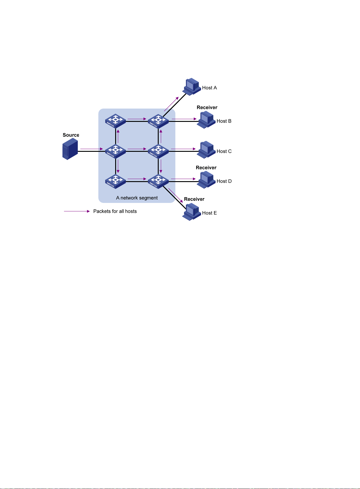
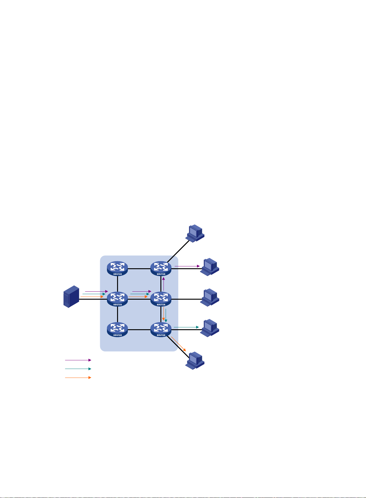
Broadcast
In broadcast transmission, the information source sends information to all hosts on the subnet, even
if some hosts do not need the information.
Figure 2 Broadcast transmission
Multicast
In Figure 2, only Host B, Host D, and Host E need the information. If the information is broadcast to
the subnet, Host A and Host C also receive it. In addition to information security issues, broadcasting
to hosts that do not need the information also causes traffic flooding on the same subnet.
Broadcast is disadvantageous in transmitting data to specific hosts. Moreover, broadcast
transmission is a significant waste of network resources.
Multicast provides point-to-multipoint data transmissions with the minimum network consumption.
When some hosts on the network need multicast information, the information sender, or multicast
source, sends only one copy of the information. Multicast distribution trees are built through multicast
routing protocols, and the packets are replicated only on nodes where the trees branch.
2
Page 13
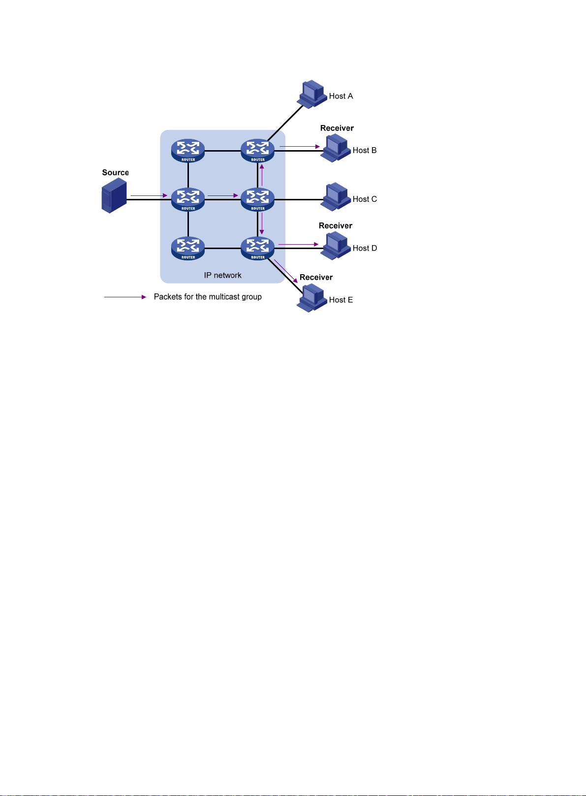
Figure 3 Multicast transmission
The multicast source sends only one copy of the information to a multicast group. Host B, Host D,
and Host E, which are information receivers, must join the multicast group. The routers on the
network duplicate and forward the information based on the distribution of the group members.
Finally, the information is correctly delivered to Host B, Host D, and Host E.
To summarize, multicast has the following advantages:
• Advantages over unicast—Multicast data is replicated and distributed until it flows to the
farthest-possible node from the source. The increase of receiver hosts will not remarkably
increase the load of the source or the usage of network resources.
• Advantages over broadcast—Multicast data is sent only to the receivers that need it. This
saves network bandwidth and enhances network security. In addition, multicast data is not
confined to the same subnet.
Multicast features
• A multicast group is a multicast receiver set identified by an IP multicast address. Hosts must
join a multicast group to become members of the multicast group before they receive the
multicast data addressed to that multicast group. Typically, a multicast source does not need to
join a multicast group.
• A multicast source is an information sender. It can send data to multiple multicast groups at the
same time. Multiple multicast sources can send data to the same multicast group at the same
time.
• The group memberships are dynamic. Hosts can join or leave multicast groups at any time.
Multicast groups are not subject to geographic restrictions.
• Multicast routers or Layer 3 multicast devices are routers or Layer 3 switches that support Layer
3 multicast. They provide multicast routing and manage multicast group memberships on stub
subnets with attached group members. A multicast router itself can be a multicast group
member.
For a better understanding of the multicast concept, you can compare multicast transmission to the
transmission of TV programs.
3
Page 14

Table 1 Comparing TV program transmission and multicast transmission
TV program transmission Multicast transmission
A TV station transmits a TV program through a
channel.
A user tunes the TV set to the channel. A receiver joins the multicast group.
The user starts to watch the TV program
transmitted by the TV station on the channel.
The user turns off the TV set or tunes to another
channel.
Common notations in multicast
The following notations are commonly used in multicast transmission:
• (*, G)—Rendezvous point tree (RPT), or a multicast packet that any multicast source sends to
multicast group G. The asterisk (*) represents any multicast source, and "G" represents a
specific multicast group.
• (S, G)—Shortest path tree (SPT), or a multicast packet that multicast source "S" sends to
multicast group "G." "S" represents a specific multicast source, and "G" represents a specific
multicast group.
For more information about the concepts RPT and SPT, see "Configuring PIM" and "Configuring
IPv6 PIM."
A multicast source sends multicast data to a multicast
group.
The receiver starts to receive the multicast data sent by
the source to the multicast group.
The receiver leaves the multicast group or joins another
group.
Multicast benefits and applications
Multicast benefits
• Enhanced efficiency—Reduces the processor load of information source servers and network
devices.
• Optimal performance—Reduces redundant traffic.
• Distributed application—Enables point-to-multipoint applications at the price of minimum
network resources.
Multicast applications
• Multimedia and streaming applications, such as Web TV, Web radio, and real-time video/audio
conferencing
• Communication for training and cooperative operations, such as distance learning and
telemedicine
• Data warehouse and financial applications (stock quotes)
• Any other point-to-multipoint application for data distribution
Multicast models
Based on how the receivers treat the multicast sources, the multicast models include any-source
multicast (ASM), source-filtered multicast (SFM), and source-specific multicast (SSM).
4
Page 15

ASM model
In the ASM model, any multicast sources can send information to a multicast group. Receivers can
join a multicast group and get multicast information addressed to that multicast group from any
multicast sources. In this model, receivers do not know the positions of the multicast sources in
advance.
SFM model
The SFM model is derived from the ASM model. To a multicast source, the two models appear to
have the same multicast membership architecture.
The SFM model functionally extends the ASM model. The upper-layer software checks the source
address of received multicast packets and permits or denies multicast traffic from specific sources.
The receivers obtain the multicast data from only part of the multicast sources. To a receiver,
multicast sources are not all valid, but are filtered.
SSM model
The SSM model provides a transmission service that enables multicast receivers to specify the
multicast sources in which they are interested.
In the SSM model, receivers have already determined the locations of the multicast sources. This is
the main difference between the SSM model and the ASM model. In addition, the SSM model uses a
different multicast address range than the ASM/SFM model. Dedicated multicast forwarding paths
are established between receivers and the specified multicast sources.
Multicast architecture
IP multicast addresses the following issues:
• Where should the multicast source transmit information to? (Multicast addressing.)
• What receivers exist on the network? (Host registration.)
• Where is the multicast source that will provide data to the receivers? (Multicast source
discovery.)
• How is the information transmitted to the receivers? (Multicast routing.)
IP multicast is an end-to-end service. The multicast architecture involves the following parts:
• Addressing mechanism—A multicast source sends information to a group of receivers
through a multicast address.
• Host registration—Receiver hosts can join and leave multicast groups dynamically. This
mechanism is the basis for management of group memberships.
• Multicast routing—A multicast distribution tree (a forwarding path tree for multicast data on the
network) is constructed for delivering multicast data from a multicast source to receivers.
• Multicast applications—A software system that supports multicast applications, such as video
conferencing, must be installed on multicast sources and receiver hosts. The TCP/IP stack
must support reception and transmission of multicast data.
Multicast addresses
IP multicast addresses
• IPv4 multicast addresses:
IANA assigned the Class D address block (224.0.0.0 to 239.255.255.255) to IPv4 multicast.
5
Page 16

Table 2 Class D IP address blocks and description
r
Address block Description
Reserved permanent group addresses. The IP address
224.0.0.0 is reserved. Other IP addresses can be used by
routing protocols and for topology searching, protocol
224.0.0.0 to 224.0.0.255
224.0.1.0 to 238.255.255.255
239.0.0.0 to 239.255.255.255
NOTE:
maintenance, and so on. Table 3 lists comm
group addresses. A packet destined for an address in this
block will not be forwarded beyond the local subnet regardless
of the TTL value in the IP header.
Globally scoped group addresses. This block includes the
following types of designated group addresses:
• 232.0.0.0/8—SSM group addresses.
• 233.0.0.0/8—Glop group addresses.
Administratively scoped multicast addresses. These
addresses are considered locally unique rather than globally
unique. You can reuse them in domains administered by
different organizations without causing conflicts. For more
information, see RFC 2365.
on permanent
Glop is a mechanism for assigning multicast addresses between different ASs. By filling an AS
number into the middle two bytes of 233.0.0.0, you get 255 multicast addresses for that AS. Fo
more information, see RFC 2770.
Table 3 Common permanent multicast group addresses
Address Description
224.0.0.1 All systems on this subnet, including hosts and routers.
224.0.0.2 All multicast routers on this subnet.
224.0.0.3 Unassigned.
224.0.0.4 DVMRP routers.
224.0.0.5 OSPF routers.
224.0.0.6 OSPF designated routers and backup designated routers.
224.0.0.7 Shared Tree (ST) routers.
224.0.0.8 ST hosts.
224.0.0.9 RIPv2 routers.
224.0.0.11 Mobile agents.
224.0.0.12 DHCP server/relay agent.
224.0.0.13 All Protocol Independent Multicast (PIM) routers.
224.0.0.14 RSVP encapsulation.
224.0.0.15 All Core-Based Tree (CBT) routers.
224.0.0.16 Designated SBM.
224.0.0.17 All SBMs.
224.0.0.18 VRRP.
• IPv6 multicast addresses:
6
Page 17

Figure 4 IPv6 multicast format
The following describes the fields of an IPv6 multicast address:
{ 0xFF—The most significant eight bits are 11111111.
{ Flags—The Flags field contains four bits.
Figure 5 Flags field format
Table 4 Flags field description
Bit Description
0 Reserved, set to 0.
• When set to 0, this address is an IPv6 multicast
address without an embedded RP address.
R
• When set to 1, this address is an IPv6 multicast
address with an embedded RP address. (The P and T
bits must also be set to 1.)
• When set to 0, this address is an IPv6 multicast
address not based on a unicast prefix.
P
• When set to 1, this address is an IPv6 multicast
address based on a unicast prefix. (The T bit must also
be set to 1.)
• When set to 0, this address is an IPv6 multicast
T
address permanently-assigned by IANA.
• When set to 1, this address is a transient, or
dynamically assigned IPv6 multicast address.
Scope—The Scope field contains four bits, which represent the scope of the IPv6
{
internetwork for which the multicast traffic is intended.
Table 5 Values of the Scope field
Value Meaning
0, F Reserved.
1 Interface-local scope.
2 Link-local scope.
3 Subnet-local scope.
4 Admin-local scope.
5 Site-local scope.
6, 7, 9 through D Unassigned.
8 Organization-local scope.
7
Page 18
Value Meaning
E Global scope.
{ Group ID—The Group ID field contains 112 bits. It uniquely identifies an IPv6 multicast
group in the scope that the Scope field defines.
Ethernet multicast MAC addresses
• IPv4 multicast MAC addresses:
As defined by IANA, the most significant 24 bits of an IPv4 multicast MAC address are
0x01005E. Bit 25 is 0, and the other 23 bits are the least significant 23 bits of an IPv4 multicast
address.
Figure 6 IPv4-to-MAC address mapping
The most significant four bits of an IPv4 multicast address are fixed at 1110. In an IPv4-to-MAC
address mapping, five bits of the IPv4 multicast address are lost. As a result, 32 IPv4 multicast
addresses are mapped to the same IPv4 multicast MAC address. A device might receive
unwanted multicast data at Layer 2 processing, which needs to be filtered by the upper layer.
• IPv6 multicast MAC addresses:
As defined by IANA, the most significant 16 bits of an IPv6 multicast MAC address are 0x3333.
The least significant 32 bits are mapped from the least significant 32 bits of an IPv6 multicast
address. Therefore, the problem of duplicate IPv6-to-MAC address mapping also arises like
IPv4-to-MAC address mapping.
Figure 7 IPv6-to-MAC address mapping
Multicast protocols
Multicast protocols include the following categories:
• Layer 3 and Layer 2 multicast protocols:
{ Layer 3 multicast refers to IP multicast operating at the network layer.
8
Page 19
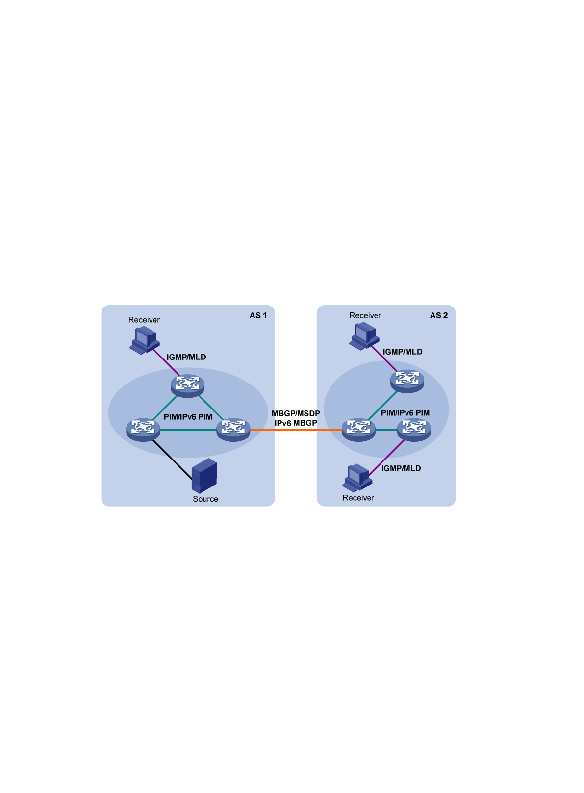
Layer 3 multicast protocols—IGMP, MLD, PIM, IPv6 PIM, MSDP, MBGP, and IPv6
MBGP.
{ Layer 2 multicast refers to IP multicast operating at the data link layer.
Layer 2 multicast protocols—IGMP snooping, MLD snooping, PIM snooping, IPv6 PIM
snooping, multicast VLAN, and IPv6 multicast VLAN.
• IPv4 and IPv6 multicast protocols:
{ For IPv4 networks—IGMP snooping, PIM snooping, multicast VLAN, IGMP, PIM, MSDP,
and MBGP.
{ For IPv6 networks—MLD snooping, IPv6 PIM snooping, IPv6 multicast VLAN, MLD, IPv6
PIM, and IPv6 MBGP.
This section provides only general descriptions about applications and functions of the Layer 2 and
Layer 3 multicast protocols in a network. For more information about these protocols, see the related
chapters.
Layer 3 multicast protocols
Layer 3 multicast protocols include multicast group management protocols and multicast routing
protocols.
Figure 8 Positions of Layer 3 multicast protocols
• Multicast group management protocols:
Internet Group Management Protocol (IGMP) and Multicast Listener Discovery (MLD) protocol
are multicast group management protocols. Typically, they run between hosts and Layer 3
multicast devices that directly connect to the hosts to establish and maintain multicast group
memberships.
• Multicast routing protocols:
A multicast routing protocol runs on Layer 3 multicast devices to establish and maintain
multicast routes and correctly and efficiently forward multicast packets. Multicast routes
constitute loop-free data transmission paths (also known as multicast distribution trees) from a
data source to multiple receivers.
In the ASM model, multicast routes include intra-domain routes and inter-domain routes.
{ An intra-domain multicast routing protocol discovers multicast sources and builds multicast
distribution trees within an AS to deliver multicast data to receivers. Among a variety of
mature intra-domain multicast routing protocols, PIM is most widely used. Based on the
forwarding mechanism, PIM has dense mode (often referred to as PIM-DM) and sparse
mode (often referred to as PIM-SM).
9
Page 20
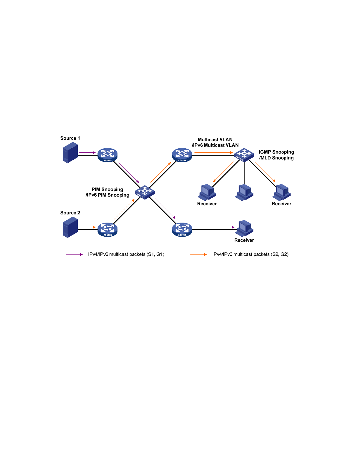
{ An inter-domain multicast routing protocol is used for delivering multicast information
between two ASs. So far, mature solutions include Multicast Source Discovery Protocol
(MSDP) and MBGP. MSDP propagates multicast source information among different ASs.
MBGP is an extension of the MP-BGP for exchanging multicast routing information among
different ASs.
For the SSM model, multicast routes are not divided into intra-domain routes and inter-domain
routes. Because receivers know the positions of the multicast sources, channels established
through PIM-SM are sufficient for the transport of multicast information.
Layer 2 multicast protocols
Layer 2 multicast protocols include IGMP snooping, MLD snooping, PIM snooping, IPv6 PIM
snooping, multicast VLAN, and IPv6 multicast VLAN.
Figure 9 Positions of Layer 2 multicast protocols
• IGMP snooping and MLD snooping:
IGMP snooping and MLD snooping are multicast constraining mechanisms that run on Layer 2
devices. They manage and control multicast groups by monitoring and analyzing IGMP or MLD
messages exchanged between the hosts and Layer 3 multicast devices. This effectively
controls the flooding of multicast data in Layer 2 networks.
• PIM snooping and IPv6 PIM snooping:
PIM snooping and IPv6 PIM snooping run on Layer 2 devices. They work with IGMP snooping
or MLD snooping to analyze received PIM messages. Then, they add the ports that are
interested in specific multicast data to a PIM snooping routing entry or IPv6 PIM snooping
routing entry. In this way, multicast data can be forwarded to only the ports that are interested in
the data.
• Multicast VLAN and IPv6 multicast VLAN:
Multicast VLAN or IPv6 multicast VLAN runs on a Layer 2 device in a multicast network where
multicast receivers for the same group exist in different VLANs. With these protocols, the Layer
3 multicast device sends only one copy of multicast to the multicast VLAN or IPv6 multicast
VLAN on the Layer 2 device. This method avoids waste of network bandwidth and extra burden
on the Layer 3 device.
10
Page 21

Multicast packet forwarding mechanism
In a multicast model, receiver hosts of a multicast group are usually located at different areas on the
network. They are identified by the same multicast group address. To deliver multicast packets to
these receivers, a multicast source encapsulates the multicast data in an IP packet with the multicast
group address as the destination address. Multicast routers on the forwarding paths forward
multicast packets that an incoming interface receives through multiple outgoing interfaces.
Compared to a unicast model, a multicast model is more complex in the following aspects:
• To ensure multicast packet transmission on the network, different routing tables are used to
guide multicast forwarding. These routing tables include unicast routing tables, routing tables
for multicast (for example, the MBGP routing table), and static multicast routing tables.
• To process the same multicast information from different peers received on different interfaces,
the multicast device performs an RPF check on each multicast packet. The RPF check result
determines whether the packet will be forwarded or discarded. The RPF check mechanism is
the basis for most multicast routing protocols to implement multicast forwarding.
For more information about the RPF mechanism, see "Configuring multicast routing and
rding" and "Configuring IPv6 multicast routing and forwarding."
forwa
11
Page 22

Configuring IGMP snooping
Overview
IGMP snooping runs on a Layer 2 device as a multicast constraining mechanism to improve
multicast forwarding efficiency. It creates Layer 2 multicast forwarding entries from IGMP packets
that are exchanged between the hosts and the router.
As shown in Figure 10, when IGMP
packets to all hosts in a VLAN. When IGMP snooping is enabled, the Layer 2 switch forwards
multicast packets of known multicast groups to only the receivers.
Figure 10 Multicast packet transmission without and with IGMP snooping
snooping is not enabled, the Layer 2 switch floods multicast
IGMP snooping ports
As shown in Figure 11, IGMP snooping runs on Switch A and Switch B, and Host A and Host C are
receivers in a multicast group. IGMP snooping ports are divided into member ports and router ports.
12
Page 23

Figure 11 IGMP snooping ports
Router ports
On an IGMP snooping Layer 2 device, the ports toward Layer 3 multicast devices are called router
ports. In Figure 11, Gig
router ports.
abitEthernet 1/0/1 of Switch A and GigabitEthernet 1/0/1 of Switch B are
Router ports contain the following types:
• Dynamic router port—When a port receives an IGMP general query whose source address is
not 0.0.0.0 or receives a PIM hello message, the port is added into the dynamic router port list.
At the same time, an aging timer is started for the port. If the port receives either of the
messages before the timer expires, the timer is reset. If the port does not receive either of the
messages when the timer expires, the port is removed from the dynamic router port list.
• Static router port—When a port is statically configured as a router port, it is added into the
static router port list. The static router port does not age out, and it can be deleted only
manually.
Do not confuse the "router port" in IGMP snooping with the "routed interface" commonly known as
the "Layer 3 interface." The router port in IGMP snooping is a Layer 2 interface.
Member ports
On an IGMP snooping Layer 2 device, the ports toward receiver hosts are called member ports.
In Figure 11, GigabitEthe
of Switch B are member ports.
Member ports contain the following types:
• Dynamic member port—When a port receives an IGMP report, it is added to the associated
dynamic IGMP snooping forwarding entry as an outgoing interface. At the same time, an aging
timer is started for the port. If the port receives an IGMP report before the timer expires, the
timer is reset. If the port does not receive an IGMP report when the timer expires, the port is
removed from the associated dynamic forwarding entry.
• Static member port—When a port is statically configured as a member port, it is added to the
associated static IGMP snooping forwarding entry as an outgoing interface. The static member
port does not age out, and it can be deleted only manually.
rnet 1/0/2 and GigabitEthernet 1/0/3 of Switch A and GigabitEthernet 1/0/2
Unless otherwise specified, router ports and member ports in this document include both static and
dynamic router ports and member ports.
13
Page 24

How IGMP snooping works
The ports in this section are dynamic ports. For information about how to configure and remove static
ports, see "Configuring static ports."
messages types include general query, IGMP report, and leave message. An IGMP
IGMP
snooping-enabled Layer 2 device performs differently depending on the message types.
General query
The IGMP querier periodically sends IGMP general queries to all hosts and routers on the local
subnet to check for the existence of multicast group members.
After receiving an IGMP general query, the Layer 2 device forwards the query to all ports in the VLAN
except the receiving port. The Layer 2 device also performs one of the following actions:
• If the receiving port is a dynamic router port in the dynamic router port list, the Layer 2 device
restarts the aging timer for the port.
• If the receiving port does not exist in the dynamic router port list, the Layer 2 device adds the
port to the dynamic router port list. It also starts an aging timer for the port.
IGMP report
A host sends an IGMP report to the IGMP querier for the following purposes:
• Responds to queries if the host is a multicast group member.
• Applies for a multicast group membership.
After receiving an IGMP report from a host, the Layer 2 device forwards the report through all the
router ports in the VLAN. It also resolves the address of the reported multicast group, and looks up
the forwarding table for a matching entry as follows:
• If no match is found, the Layer 2 device creates a forwarding entry with the receiving port as an
outgoing interface. It also marks the receiving port as a dynamic member port and starts an
aging timer for the port.
• If a match is found but the matching forwarding entry does not contain the receiving port, the
Layer 2 device adds the receiving port to the outgoing interface list. It also marks the receiving
port as a dynamic member port and starts an aging timer for the port.
• If a match is found and the matching forwarding entry contains the receiving port, the Layer 2
device restarts the aging timer for the port.
In an application with a group policy configured on an IGMP snooping-enabled Layer 2 device, when
a user requests a multicast program, the user's host initiates an IGMP report. After receiving this
report, the Layer 2 device resolves the multicast group address in the report and performs ACL
filtering on the report. If the report passes ACL filtering, the Layer 2 device creates an IGMP
snooping forwarding entry for the multicast group with the receiving port as an outgoing interface. If
the report does not pass ACL filtering, the Layer 2 device drops this report. The multicast data for the
multicast group is not sent to this port, and the user cannot retrieve the program.
A Layer 2 device does not forward an IGMP report through a non-router port because of the host
IGMP report suppression mechanism. For more information about the mechanism, see "Configuring
IGMP."
Leave message
An IGMPv1 receiver host does not send any leave messages when it leaves a multicast group. The
Layer 2 device cannot immediately update the status of the port that connects to the receiver host.
The Layer 2 device does not remove the port from the outgoing interface list in the associated
forwarding entry until the aging time for the group expires.
An IGMPv2 or IGMPv3 host sends an IGMP leave message when it leaves a multicast group.
When the Layer 2 device receives an IGMP leave message on a dynamic member port, the Layer 2
device first examines whether a forwarding entry matches the group address in the message.
14
Page 25

• If no match is found, the Layer 2 device discards the IGMP leave message.
• If a match is found but the receiving port is not an outgoing interface in the forwarding entry, the
Layer 2 device discards the IGMP leave message.
• If a match is found and the receiving port is not the only outgoing interface in the forwarding
entry, the Layer 2 device performs the following actions:
{ Discards the IGMP leave message.
{ Sends an IGMP group-specific query to identify whether the group has active receivers
attached to the receiving port.
{ Sets the aging timer for the receiving port to twice the IGMP last member query interval.
• If a match is found and the receiving port is the only outgoing interface in the forwarding entry,
the Layer 2 device performs the following actions:
{ Forwards the IGMP leave message to all router ports in the VLAN.
{ Sends an IGMP group-specific query to identify whether the group has active receivers
attached to the receiving port.
{ Sets the aging timer for the receiving port to twice the IGMP last member query interval.
After receiving the IGMP leave message on a port, the IGMP querier resolves the multicast group
address in the message. Then, it sends an IGMP group-specific query to the multicast group through
the receiving port.
After receiving the IGMP group-specific query, the Layer 2 device forwards the query through all its
router ports in the VLAN and all member ports of the multicast group. Then, it waits for the
responding IGMP report from the directly connected hosts. For the dynamic member port that
received the leave message, the Layer 2 device also performs one of the following actions:
• If the port receives an IGMP report before the aging timer expires, the Layer 2 device resets the
aging timer.
• If the port does not receive an IGMP report when the aging timer expires, the Layer 2 device
removes the port from the forwarding entry for the multicast group.
Protocols and standards
RFC 4541, Considerations for Internet Group Management Protocol (IGMP) and Multicast Listener
Discovery (MLD) Snooping Switches
General configuration restrictions and guidelines
When you configure IGMP snooping, follow these restrictions and guidelines:
• For a VLAN configured with IGMP snooping, if you change the VPN instance bound to the
VLAN interface, Layer 2 multicast traffic for the VLAN is interrupted. In this case, you must
execute the reset igmp-snooping group command so that new IGMP snooping forwarding
entries can be created.
• For IGMP reports received from secondary VLANs, the relevant IGMP snooping forwarding
entries are maintained by the primary VLAN. Therefore, you need to configure IGMP snooping
only for the primary VLAN. The IGMP snooping configuration made for secondary VLANs does
not take effect. For more information about primary VLANs and secondary VLANs, see Layer
2—LAN Switching Configuration Guide.
• The IGMP snooping configurations made on Layer 2 aggregate interfaces do not interfere with
the configurations made on member ports. In addition, the configurations made on Layer 2
aggregate interfaces do not take part in aggregation calculations. The configuration made on a
member port of the aggregate group takes effect after the port leaves the aggregate group.
15
Page 26

IGMP snooping configuration task list
Tasks at a glance
Configuring basic IGMP snooping features:
• (Required.) Enabling IGMP snooping
• (Optiona
• (Optional.) Setting the maximum number of IGMP snooping forwarding entries
• (Optional.) Setting the IGMP last member query interval
Configuring IGMP snooping port features:
• (Optional.) Setting aging timers for dynamic ports
• (Optional.) Configuring static ports
• (Optional.) Configuring a port as a simulated member host
• (Optiona
• (Optional.) Disabling a port from becoming a dynamic router port
Configuring the IGMP snooping querier:
• (Optional.) Enabling the IGMP snooping querier
• (Optional.) Configuring parameters for IGMP general queries and responses
Configuring parameters for IGMP messages:
• (Optional.) Configuring source IP addresses for IGMP messages
• (Optiona
Configuring IGMP snooping policies:
• (Optional.) Configuring a multicast group policy
• (Optiona
• (Optional.) Enabling dropping unknown multicast data
• (Optional.) Enabling IGMP report suppression
• (Optional.) Setting the maximum number of multicast groups on a port
• (Optional.) Enabling multicast group replacement
l.) Specifying an IGMP snooping version
l.) Enabling fast-leave processing
l.) Setting the 802.1p priority for IGMP messages
l.) Enabling multicast source port filtering
Configuring basic IGMP snooping features
Before you configure basic IGMP snooping features, complete the following tasks:
• Configure VLANs.
• Determine the IGMP snooping version.
• Determine the maximum number of IGMP snooping forwarding entries.
• Determine the IGMP last member query interval.
Enabling IGMP snooping
When you enable IGMP snooping, follow these guidelines:
• You must enable IGMP snooping globally before you enable it for a VLAN.
• IGMP snooping configuration made in VLAN view takes effect only on the member ports in that
VLAN.
• You can enable IGMP snooping for the specified VLANs in IGMP-snooping view or for a VLAN
in VLAN view. For a VLAN, the configuration in VLAN view has the same priority as the
configuration in IGMP-snooping view, and the most recent configuration takes effect.
16
Page 27

Enabling IGMP snooping for the specified VLANs
Step Command Remarks
1. Enter system view.
2. Enable IGMP snooping
globally and enter
IGMP-snooping view.
3. Enable IGMP snooping for
the specified VLANs.
system-view
igmp-snooping
enable vlan
vlan-list
Enabling IGMP snooping for a VLAN
Step Command Remarks
1. Enter system view.
2. Enable IGMP snooping
globally and enter
IGMP-snooping view.
3. Return to system view.
4. Enter VLAN view.
5. Enable IGMP snooping for
the VLAN.
system-view
igmp-snooping
quit
vlan
vlan-id
igmp-snooping enable
Specifying an IGMP snooping version
N/A
By default, IGMP snooping is
globally disabled.
By default, IGMP snooping is
disabled for a VLAN.
N/A
By default, IGMP snooping is
disabled.
N/A
N/A
By default, IGMP snooping is
disabled in a VLAN.
Different IGMP snooping versions process different versions of IGMP messages.
• IGMPv2 snooping processes IGMPv1 and IGMPv2 messages, but it floods IGMPv3 messages
in the VLAN instead of processing them.
• IGMPv3 snooping processes IGMPv1, IGMPv2, and IGMPv3 messages.
If you change IGMPv3 snooping to IGMPv2 snooping, the switch does the following:
• Clears all IGMP snooping forwarding entries that are dynamically added.
• Keeps static IGMPv3 snooping forwarding entries (*, G).
• Clears static IGMPv3 snooping forwarding entries (S, G), which will be restored when IGMP
snooping is switched back to IGMPv3 snooping.
For more information about static IGMP snooping forwarding entries, see "Configuring static ports."
You can specify the version for the specified VLANs in IGMP-snooping view or for a VLAN in VLAN
view. For a VLAN, the configuration in VLAN view has the same priority as the configuration in
IGMP-snooping view, and the most recent configuration takes effect.
Specifying an IGMP snooping version for the specified VLANs
Step Command Remarks
1. Enter system view.
2. Enable IGMP snooping
globally and enter
IGMP-snooping view.
system-view
igmp-snooping
N/A
N/A
3. Specify an IGMP snooping
version for the specified
version
vlan-list
version-number
17
vlan
The default setting is 2.
Page 28

VLANs.
Specifying an IGMP snooping version for a VLAN
Step Command Remarks
1. Enter system view.
2. Enter VLAN view.
3. Specify an IGMP snooping
version for the VLAN.
system-view
vlan
vlan-id
igmp-snooping version
version-number
N/A
N/A
The default setting is 2.
Setting the maximum number of IGMP snooping forwarding entries
You can set the maximum number of IGMP snooping forwarding entries, including dynamic entries
and static entries. When the number of forwarding entries on the switch reaches the upper limit, the
switch does not automatically remove any existing entries. As a best practice, manually remove
some entries to allow new entries to be created.
To set the maximum number of IGMP snooping forwarding entries:
Step Command Remarks
1. Enter system view.
2. Enter IGMP-snooping view.
3. Set the maximum number of
IGMP snooping forwarding
entries.
system-view
igmp-snooping
entry-limit
N/A
limit
N/A
The default setting is
4294967295.
Setting the IGMP last member query interval
A receiver host starts a report delay timer for a multicast group when it receives an IGMP
group-specific query for the group. This timer is set to a random value in the range of 0 to the
maximum response time advertised in the query. When the timer value decreases to 0, the host
sends an IGMP report to the group.
The IGMP last member query interval defines the maximum response time advertised in IGMP
group-specific queries. Set an appropriate value for the IGMP last member query interval to speed
up hosts' responses to IGMP group-specific queries and avoid IGMP report traffic bursts.
Configuration restrictions and guidelines
When you set the IGMP last member query interval, follow these restrictions and guidelines:
• The Layer 2 device does not send an IGMP group-specific query if it receives an IGMP leave
message from a port enabled with fast-leave processing.
• You can set the IGMP last member query interval globally for all VLANs in IGMP-snooping view
or for a VLAN in VLAN view. For a VLAN, the VLAN-specific configuration takes priority over the
global configuration.
Setting the IGMP last member query interval globally
Step Command Remarks
1. Enter system view.
system-view
N/A
18
Page 29

Step Command Remarks
2. Enter IGMP-snooping view.
3. Set the IGMP last member
query interval globally.
igmp-snooping
last-member-query-interval
interval
Setting the IGMP last member query interval in a VLAN
Step Command Remarks
1. Enter system view.
2. Enter VLAN view.
system-view
vlan
vlan-id N/A
N/A
The default setting is 1
second.
N/A
3. Set the IGMP last member
query interval for the VLAN.
igmp-snooping
last-member-query-interval
interval
The default setting is 1
second.
Configuring IGMP snooping port features
Before you configure IGMP snooping port features, complete the following tasks:
• Enable IGMP snooping for the VLAN.
• Determine the aging timer for dynamic router ports.
• Determine the aging timer for dynamic member ports.
• Determine the addresses of the multicast group and multicast source.
Setting aging timers for dynamic ports
When you set aging timers for dynamic ports, follow these guidelines:
• If the memberships of multicast groups frequently change, you can set a relatively small value
for the aging timer of the dynamic member ports. If the memberships of multicast groups rarely
change, you can set a relatively large value.
• If a dynamic router port receives a PIMv2 hello message, the aging timer for the port is specified
by the hello message. In this case, the router-aging-time or igmp-snooping
router-aging-time command does not take effect on the port.
• IGMP group-specific queries originated by the Layer 2 device trigger the adjustment of aging
timers for dynamic member ports. If a dynamic member port receives such a query, its aging
timer is set to twice the IGMP last member query interval. For more information about setting
the IGMP last member query interval on the Layer 2 device, see "Setting the IGMP last member
query inte
• You can set the timers globally for all VLANs in IGMP-snooping view or for a VLAN in VLAN
view. For a VLAN, the VLAN-specific configuration takes priority over the global configuration.
rval."
Setting the aging timers for dynamic ports globally
Step Command Remarks
1. Enter system view.
2. Enter IGMP-snooping view.
3. Set the aging timer for
dynamic router ports globally.
4. Set the global aging timer for
dynamic member ports
system-view
igmp-snooping
router-aging-time
host-aging-time
N/A
19
interval
interval
N/A
The default setting is 260
seconds.
The default setting is 260
seconds.
Page 30

globally.
Setting the aging timers for dynamic ports in a VLAN
Step Command Remarks
1. Enter system view.
2. Enter VLAN view.
3. Set the aging timer for
dynamic router ports in the
VLAN.
4. Set the aging timer for
dynamic member ports in the
VLAN.
system-view
vlan
vlan-id
igmp-snooping
router-aging-time
igmp-snooping
host-aging-time
N/A
interval
Configuring static ports
You can configure the following types of static ports:
• Static member port—When you configure a port as a static member port for a multicast group,
all hosts attached to the port will receive multicast data for the group.
The static member port does not respond to IGMP queries. When you complete or cancel this
configuration on a port, the port does not send an unsolicited IGMP report or leave message.
• Static router port—When you configure a port as a static router port for a multicast group, all
multicast data for the group received on the port will be forwarded.
interval
N/A
The default setting is 260
seconds.
The default setting is 260
seconds.
To configure static ports:
Step Command Remarks
1. Enter system view.
2. Enter Layer 2 Ethernet
interface view or Layer 2
aggregate interface view.
3. Configure the port as a static
port.
system-view
interface
interface-number
• Configure the port as a static
member port:
igmp-snooping
static-group group-address
[ source-ip source-address ]
vlan vlan-id
• Configure the port as a static
router port:
igmp-snooping
static-router-port vlan
vlan-id
N/A
interface-type
N/A
By default, a port is not a static
member port or static router port.
Configuring a port as a simulated member host
When a port is configured as a simulated member host, it is equivalent to an independent host in the
following ways:
• It sends an unsolicited IGMP report when you complete the configuration.
• It responds to IGMP general queries with IGMP reports.
• It sends an IGMP leave message when you cancel the configuration.
20
Page 31

The version of IGMP running on the simulated member host is the same as the version of IGMP
snooping running on the port. The port ages out in the same way as a dynamic member port.
To configure a port as a simulated member host:
Step Command Remarks
1. Enter system view.
2. Enter Layer 2 Ethernet
interface view or Layer 2
aggregate interface view.
system-view
interface
interface-number
interface-type
N/A
N/A
3. Configure the port as a
simulated member host.
igmp-snooping host-join
group-address [
source-address ]
Enabling fast-leave processing
This feature enables the switch to immediately remove a port from the forwarding entry for a
multicast group when the port receives a leave massage.
Configuration restrictions and guidelines
When you enable fast-leaving processing, follow these restrictions and guidelines:
• Do not enable fast-leave processing on a port that has multiple receiver hosts in a VLAN. If
fast-leave processing is enabled, after a receiver host leaves a multicast group, the other
receivers cannot receive multicast data for the group.
• You can enable fast-leave processing globally for all ports in IGMP-snooping view or for a port
in interface view. For a port, the port-specific configuration takes priority over the global
configuration.
Enabling fast-leave processing globally
Step Command Remarks
1. Enter system view.
system-view
source-ip
vlan
vlan-id
N/A
By default, the port is not a
simulated member host.
2. Enter IGMP-snooping view.
3. Enable fast-leave
processing globally.
igmp-snooping
fast-leave [ vlan
vlan-list
]
N/A
By default, fast-leave processing
is disabled.
Enabling fast-leave processing on a port
Step Command Remarks
1. Enter system view.
2. Enter Layer 2 Ethernet
interface view or Layer 2
aggregate interface view.
3. Enable fast-leave
processing on the port.
system-view
interface
interface-number
igmp-snooping fast-leave [ vlan
vlan-list
N/A
interface-type
]
N/A
By default, fast-leave processing
is disabled.
Disabling a port from becoming a dynamic router port
A receiver host might send an IGMP general query or PIM hello message for testing purposes. In this
case, the following problems might exist:
21
Page 32

• The port that receives the IGMP general query or PIM hello message becomes a dynamic
router port. Before its aging timer expires, this dynamic router port receives all multicast packets
within the VLAN where the port belongs and forwards them to the host. The receiver host will
receive multicast data that it does not want to receive.
• The IGMP general query or PIM hello message that the host sends affects the multicast routing
protocol state on Layer 3 devices, such as the IGMP querier or DR election. This might further
cause network interruption.
To solve these problems and to improve network security and the control over multicast users, you
can disable a port from becoming a dynamic router port.
To disable a port from becoming a dynamic router port:
Step Command Remarks
1. Enter system view.
2. Enter Layer 2 Ethernet
interface view or Layer 2
aggregate interface view.
3. Disable the port from
becoming a dynamic router
port.
system-view
interface
interface-number
igmp-snooping
router-port-deny [ vlan
interface-type
vlan-list
N/A
N/A
By default, a port can become a
dynamic router port.
This configuration does not affect
]
the static router port
configuration.
Configuring the IGMP snooping querier
This section describes how to configure an IGMP snooping querier.
Configuration prerequisites
Before you configure the IGMP snooping querier, complete the following tasks:
• Enable IGMP snooping for the VLAN.
• Determine the IGMP general query interval.
• Determine the maximum response time for IGMP general queries.
Enabling the IGMP snooping querier
This feature enables the switch to periodically send IGMP general queries to establish and maintain
multicast forwarding entries at the data link Layer. You can configure an IGMP snooping querier on a
network without Layer 3 multicast devices.
Do not enable the IGMP snooping querier on a multicast network that runs IGMP. An IGMP snooping
querier does not take part in IGMP querier elections. However, it might affect IGMP querier elections
if it sends IGMP general queries with a low source IP address.
To enable the IGMP snooping querier for a VLAN:
Step Command Remarks
1. Enter system view.
2. Enter VLAN view.
3. Enable the IGMP snooping
querier.
system-view
vlan-id
22
vlan
igmp-snooping querier
N/A
N/A
By default, the IGMP snooping
querier is disabled.
Page 33

Configuring parameters for IGMP general queries and responses
CAUTION:
To avoid mistakenly deleting multicast group members, make sure the IGMP general query interval
is greater than the maximum response time for IGMP general queries.
You can modify the IGMP general query interval for a VLAN based on the actual condition of the
network.
A receiver host starts a report delay timer for each multicast group that it has joined when it receives
an IGMP general query. This timer is set to a random value in the range of 0 to the maximum
response time advertised in the query. When the timer value decreases to 0, the host sends an IGMP
report to the corresponding multicast group.
Configuration restrictions and guidelines
When you configure parameters for IGMP general queries and responses, follow these restrictions
and guidelines:
• Set an appropriate value for the maximum response time for IGMP general queries to speed up
hosts' responses to IGMP general queries and avoid IGMP report traffic bursts.
• You can configure set the maximum response time for IGMP general queries globally for all
VLANs in IGMP-snooping view or for a VLAN in VLAN view. For a VLAN, the VLAN-specific
configuration takes priority over the global configuration.
Configuring the parameters for IGMP general queries and responses globally
Step Command Remarks
1. Enter system view.
2. Enter IGMP-snooping view.
3. Set the maximum response
time for IGMP general
queries.
system-view
igmp-snooping
max-response-time
interval
N/A
N/A
The default setting is 10 seconds.
Configuring parameters for IGMP general queries and responses in a VLAN
Step Command Remarks
1. Enter system view.
2. Enter VLAN view.
3. Set the IGMP general query
interval in the VLAN.
4. Set the maximum response
time for IGMP general
queries in the VLAN.
system-view
vlan
vlan-id N/A
igmp-snooping query-interval
interval
igmp-snooping
max-response-time
interval
N/A
The default setting is 125
seconds.
The default setting is 10 seconds.
Configuring parameters for IGMP messages
This section describes how to configure parameters for IGMP messages.
23
Page 34

Configuration prerequisites
Before you configure parameters for IGMP messages, complete the following tasks:
• Enable IGMP snooping for the VLAN.
• Determine the source IP address of IGMP general queries.
• Determine the source IP address of IGMP group-specific queries.
• Determine the source IP address of IGMP reports.
• Determine the source IP address of IGMP leave messages.
• Determine the 802.1p priority of IGMP messages
Configuring source IP addresses for IGMP messages
The IGMP snooping querier might send IGMP general queries with the source IP address 0.0.0.0.
The port that receives such queries will not be maintained as a dynamic router port. This might
prevent the associated dynamic IGMP snooping forwarding entry from being correctly created at the
data link layer and eventually cause multicast traffic forwarding failures.
To avoid this problem, you can configure a non-all-zero IP address as the source IP address of the
IGMP queries on the IGMP snooping querier. This configuration might affect the IGMP querier
election within the subnet.
You can also change the source IP address of IGMP reports or leave messages sent by a simulated
member host.
To configure source IP addresses for IGMP messages in a VLAN:
Step Command Remarks
1. Enter system view.
2. Enter VLAN view.
3. Configure the source IP
address for IGMP general
queries.
4. Configure the source IP
address for IGMP
group-specific queries.
system-view
vlan-id
vlan
igmp-snooping
general-query source-ip
ip-address
igmp-snooping
special-query source-ip
ip-address
N/A
N/A
By default, the source IP address of
IGMP general queries is the IP
address of the current VLAN
interface. If the current VLAN
interface does not have an IP
address, the source IP address is
0.0.0.0.
By default, the source IP address of
IGMP group-specific queries is one of
the following:
• The source address of IGMP
• The IP address of the current
• 0.0.0.0 if the IGMP snooping
group-specific queries if the
IGMP snooping querier has
received IGMP general queries.
VLAN interface if the IGMP
snooping querier does not
receive an IGMP general query.
querier does not receive an
IGMP general query and the
current VLAN interface does not
have an IP address.
5. Configure the source IP
address for IGMP reports.
igmp-snooping report
source-ip
ip-address
24
By default, the source IP address of
IGMP reports is the IP address of the
current VLAN interface. If the current
Page 35

VLAN interface does not have an IP
address, the source IP address is
0.0.0.0.
By default, the source IP address of
6. Configure the source IP
address for IGMP leave
messages.
igmp-snooping leave
source-ip
ip-address
IGMP leave messages is the IP
address of the current VLAN
interface. If the current VLAN
interface does not have an IP
address, the source IP address is
0.0.0.0.
Setting the 802.1p priority for IGMP messages
When congestion occurs on outgoing ports of the switch, it forwards IGMP messages in their 802.1p
priority order, from highest to lowest. You can assign higher 802.1p priority to IGMP messages that
are created or forwarded by the switch.
You can set the 802.1p priority globally for all VLANs in IGMP-snooping view or for a VLAN in VLAN
view. For a VLAN, the VLAN-specific configuration takes priority over the global configuration.
Setting the 802.1p priority for IGMP messages globally
Step Command Remarks
1. Enter system view.
2. Enter IGMP-snooping view.
system-view
igmp-snooping
N/A
N/A
3. Set the 802.1p priority for
IGMP messages.
dot1p-priority
priority-number
The default setting is 0.
The global configuration takes
effect on all VLANs.
Setting the 802.1p priority for IGMP messages in a VLAN
Step Command Remarks
1. Enter system view.
2. Enter VLAN view.
3. Set the 802.1p priority for
IGMP messages in the
VLAN.
system-view
vlan
vlan-id N/A
igmp-snooping dot1p-priority
priority-number
N/A
The default setting is 0.
Configuring IGMP snooping policies
Before you configure IGMP snooping policies, complete the following tasks:
• Enable IGMP snooping for the VLAN.
• Determine the ACL to be used by the multicast group policy.
• Determine the maximum number of multicast groups that a port can join.
Configuring a multicast group policy
This feature enables the switch to filter IGMP reports based on the used ACL that specifies the
multicast groups and the optional sources. Use this feature to control the multicast groups that
receiver hosts can join.
25
Page 36

Configuration restrictions and guidelines
When you configure a multicast group policy, follow these guidelines:
• This configuration takes effect only on the multicast groups that ports join dynamically.
• You can configure a multicast group policy globally for all ports in IGMP-snooping view or for a
port in interface view. For a port, the port-specific configuration takes priority over the global
configuration.
Configuring a multicast group policy globally
Step Command Remarks
1. Enter system view.
2. Enter IGMP-snooping view.
system-view
igmp-snooping
N/A
N/A
3. Configure a multicast group
policy globally.
group-policy
vlan-list
]
acl-number [
Configuring a multicast group policy on a port
Step Command Remarks
1. Enter system view.
2. Enter Layer 2 Ethernet
interface view or Layer 2
aggregate interface view.
3. Configure a multicast group
policy on the port.
system-view
interface
interface-number
igmp-snooping group-policy
acl-number [
N/A
vlan-list
]
interface-type
vlan
Enabling multicast source port filtering
This feature enables the switch to discard all multicast data packets and to accept multicast protocol
packets. You can enable this feature on ports that connect only to multicast receivers.
You can enable this feature for the specified ports in IGMP-snooping view or for a port in interface
view. For a port, the configuration in interface view has the same priority as the configuration in
IGMP-snooping view, and the most recent configuration takes effect.
vlan
By default, no multicast group
policies exist. Hosts can join any
multicast groups.
N/A
By default, no multicast group
policies exist on a port. Hosts
attached to the port can join any
multicast groups.
Enabling multicast source port filtering for the specified ports
Step Command Remarks
1. Enter system view.
2. Enter IGMP-snooping view.
3. Enable multicast source port
filtering.
system-view
igmp-snooping
source-deny port
interface-list
Enabling multicast source port filtering for a port
Step Command Remarks
1. Enter system view.
2. Enter Layer 2 Ethernet
interface view.
system-view
interface
interface-number
interface-type
26
N/A
N/A
By default, multicast source port
filtering is disabled.
N/A
N/A
Page 37

3. Enable multicast source port
filtering.
igmp-snooping source-deny
Enabling dropping unknown multicast data
This feature enables the switch to drop all unknown multicast data. Unknown multicast data refers to
multicast data for which no forwarding entries exist in the IGMP snooping forwarding table.
Configuration restrictions and guidelines
When you enable dropping unknown multicast data, follow these restrictions and guidelines:
• You can enable this feature globally for all VLANs in IGMP-snooping view or for a VLAN in
VLAN view.
• The drop-unknown command in IGMP-snooping view and the igmp-snooping
drop-unknown command in VLAN view are mutually exclusive. You cannot configure them on
the same switch.
• If you enable dropping unknown IPv6 and IPv4 multicast data, enable both of them globally or
for the same VLANs to ensure correct multicast forwarding. For more information about
enabling dropping unknown IPv6 multicast data, see "Configuring MLD snooping."
• Whe
Enabling dropping unknown multicast data globally
n dropping unknown multicast data is enabled, the switch still forwards unknown multicast
data to other router ports in the VLAN.
By default, multicast source port
filtering is disabled.
Step Command Remarks
1. Enter system view.
2. Enter IGMP-snooping view.
3. Enable dropping unknown
multicast data globally.
system-view
igmp-snooping
drop-unknown
N/A
Enabling dropping unknown multicast data in a VLAN
Step Command Remarks
1. Enter system view.
2. Enter VLAN view.
3. Enable dropping unknown
multicast data for the VLAN.
system-view
vlan
vlan-id
igmp-snooping drop-unknown
N/A
Enabling IGMP report suppression
N/A
By default, dropping unknown
multicast data is disabled.
Unknown multicast data is
flooded in the VLAN to which the
data belongs.
N/A
By default, dropping unknown
multicast data is disabled.
Unknown multicast data is
flooded in the VLAN to which the
data belongs.
This feature enables the switch to forward only the first IGMP report for a multicast group to its
directly connected Layer 3 device. Other reports for the same group in the same query interval are
discarded. This reduces the multicast traffic.
To enable IGMP report suppression:
27
Page 38

Step Command Remarks
1. Enter system view.
2. Enter IGMP-snooping view.
3. Enable IGMP report
suppression.
system-view
igmp-snooping
report-aggregation
N/A
N/A
By default, IGMP report
suppression is enabled.
Setting the maximum number of multicast groups on a port
You can set the maximum number of multicast groups on a port to regulate the port traffic.
Configuration restrictions and guidelines
When you set the maximum number of multicast groups on a port, follow these guidelines:
• This configuration takes effect only on the multicast groups that a port joins dynamically.
• If the number of multicast groups on a port exceeds the limit, the system removes all the
forwarding entries related to that port. The receiver hosts attached to that port can join multicast
groups again before the number of multicast groups on the port reaches the limit.
Configuration procedure
To set the maximum number of multicast groups on a port:
Step Command Remarks
1. Enter system view.
2. Enter Layer 2 Ethernet
interface view or Layer 2
aggregate interface view.
3. Set the maximum number of
multicast groups on a port.
system-view
interface
interface-number
igmp-snooping group-limit
vlan
[
N/A
interface-type
vlan-list ]
limit
N/A
The default setting is
4294967295.
Enabling multicast group replacement
This feature enables the switch to replace an existing group with a newly joined group when the
number of groups exceeds the upper limit. This feature is typically used in the channel switching
application. Without this feature, the switch discards IGMP reports for new groups, and the user
cannot change to the new channel.
Configuration restrictions and guidelines
When you enable multicast group replacement, follow these guidelines:
• This configuration takes effect only on the multicast groups that a port joins dynamically.
• You can enable this feature globally for all ports in IGMP-snooping view or for a port in interface
view. For a port, the port-specific configuration takes priority over the global configuration.
Enabling multicast group replacement globally
Step Command Remarks
1. Enter system view.
2. Enter IGMP-snooping view.
3. Enable multicast group
replacement globally.
system-view
igmp-snooping
overflow-replace [ vlan
N/A
28
vlan-list ]
N/A
By default, multicast group
replacement is disabled.
Page 39

Enabling multicast group replacement on a port
Step Command Remarks
1. Enter system view.
2. Enter Layer 2 Ethernet
interface view or Layer 2
aggregate interface view.
3. Enable multicast group
replacement on a port.
system-view
interface
interface-number
igmp-snooping
overflow-replace [ vlan
N/A
interface-type
vlan-list ]
N/A
By default, multicast group
replacement is disabled.
Displaying and maintaining IGMP snooping
Execute display commands in any view and reset commands in user view.
Task Command
Display IGMP snooping status.
display igmp-snooping
global
[
|
vlan
vlan-id ]
Display dynamic IGMP snooping
forwarding entries (in standalone mode).
Display dynamic IGMP snooping
forwarding entries (in IRF mode).
Display dynamic router port information
(in standalone mode).
Display dynamic router port information
(in IRF mode).
Display static IGMP snooping forwarding
entries (in standalone mode).
Display static IGMP snooping forwarding
entries (in IRF mode).
Display static router port information (in
standalone mode).
Display static router port information (in
IRF mode).
Display statistics for the IGMP messages
learned by IGMP snooping.
display igmp-snooping group
slot
slot
slot
vlan
vlan
slot-number ]
slot-number ]
vlan
vlan
slot-number ]
source-address ] * [
slot-number ]
display igmp-snooping group
source-address ] * [
chassis-number
display igmp-snooping router-port
slot-number ]
display igmp-snooping router-port
chassis-number
display igmp-snooping static-group
source-address ] * [
slot-number ]
display igmp-snooping static-group
source-address ] * [
chassis-number
display igmp-snooping static-router-port
slot
[
slot-number ]
display igmp-snooping static-router-port
chassis
[
display igmp-snooping statistics
chassis-number
[ group-address |
vlan-id ] [
[ group-address |
vlan-id ] [
vlan-id ] [
vlan-id ] [
slot
slot-number ]
verbose
verbose
vlan
[
vlan
[
[ group-address |
verbose
[ group-address |
verbose
slot
] [
chassis
] [
vlan-id ] [
vlan-id ] [
slot
] [
chassis
] [
vlan
[
vlan-id ]
vlan
[
vlan-id ]
slot
chassis
Display information about Layer 2 IP
multicast groups (in standalone mode).
Display information about Layer 2 IP
multicast groups (in IRF mode).
Display Layer 2 IP multicast group entries
(in standalone mode).
Display Layer 2 IP multicast group entries
(in IRF mode).
display l2-multicast ip
source-address ] * [
display l2-multicast ip
source-address ] * [
slot
slot-number ]
display l2-multicast ip forwarding
source
source-address ] * [
display l2-multicast ip forwarding
source
source-address ] * [
chassis-number
29
slot
group
[
vlan
[
vlan
slot-number ]
group-address |
vlan-id ] [
group
group-address |
vlan-id ] [
vlan
vlan
vlan-id ] [
vlan-id ] [
slot
slot-number ]
chassis
group
[
group
[
source
source
chassis-number
group-address |
slot
slot-number ]
group-address |
chassis
Page 40

Display information about Layer 2 MAC
multicast groups (in standalone mode).
display l2-multicast mac
slot-number ]
[ mac-address ] [
vlan
vlan-id ] [
slot
Display information about Layer 2 MAC
multicast groups (in IRF mode).
Display Layer 2 MAC multicast group
entries (in standalone mode).
Display Layer 2 MAC multicast group
entries (in IRF mode).
Clear dynamic IGMP snooping
forwarding entries.
Clear dynamic router port information.
Clear statistics for the IGMP messages
learned through IGMP snooping.
display l2-multicast mac
chassis
[
display l2-multicast mac forwarding
vlan-id ] [
display l2-multicast mac forwarding
vlan-id ] [
reset igmp-snooping group
[ source-address ] |
reset igmp-snooping router-port
reset igmp-snooping statistics
chassis-number
slot
slot-number ]
chassis
chassis-number
[ mac-address ] [
slot
{ group-address
all
vlan
} [
slot-number ]
slot
vlan-id ]
{
vlan
vlan-id ]
[ mac-address ] [
[ mac-address ] [
slot-number ]
all
vlan
|
vlan-id }
vlan
vlan
IGMP snooping configuration examples
Group policy and simulated joining configuration example
Network requirements
As shown in Figure 12, Router A runs IGMPv2 and acts as the IGMP querier. Switch A runs IGMPv2
snooping.
Configure a group policy and simulated joining to meet the following requirements:
• Host A and Host B receive only the multicast data addressed to multicast group 224.1.1.1.
Multicast data can be forwarded through GigabitEthernet 1/0/3 and GigabitEthernet 1/0/4 of
Switch A uninterruptedly, even though Host A and Host B fail to receive the multicast data.
• Switch A will drop unknown multicast data instead of flooding it in VLAN 100.
Figure 12 Network diagram
30
Page 41

Configuration procedure
1. Assign an IP address and subnet mask to each interface according to Figure 12. (Details not
shown.)
2. Configure Router A:
# Enable IP multicast routing.
<RouterA> system-view
[RouterA] multicast routing
[RouterA-mrib] quit
# Enable IGMP on GigabitEthernet 1/0/1.
[RouterA] interface gigabitethernet 1/0/1
[RouterA-GigabitEthernet1/0/1] igmp enable
[RouterA-GigabitEthernet1/0/1] quit
# Enable PIM-DM on GigabitEthernet 1/0/2.
[RouterA] interface gigabitethernet 1/0/2
[RouterA-GigabitEthernet1/0/2] pim dm
[RouterA-GigabitEthernet1/0/2] quit
3. Configure Switch A:
# Enable IGMP snooping globally.
<SwitchA> system-view
[SwitchA] igmp-snooping
[SwitchA-igmp-snooping] quit
# Create VLAN 100, and assign GigabitEthernet 1/0/1 through GigabitEthernet 1/0/4 to the
VLAN.
[SwitchA] vlan 100
[SwitchA-vlan100] port gigabitethernet 1/0/1 to gigabitethernet 1/0/4
# Enable IGMP snooping, and enable dropping unknown multicast data for VLAN 100.
[SwitchA-vlan100] igmp-snooping enable
[SwitchA-vlan100] igmp-snooping drop-unknown
[SwitchA-vlan100] quit
# Configure a multicast group policy so that the hosts in VLAN 100 can join only multicast group
224.1.1.1.
[SwitchA] acl number 2001
[SwitchA-acl-basic-2001] rule permit source 224.1.1.1 0
[SwitchA-acl-basic-2001] quit
[SwitchA] igmp-snooping
[SwitchA-igmp-snooping] group-policy 2001 vlan 100
[SwitchA-igmp-snooping] quit
# Configure GigabitEthernet 1/0/3 and GigabitEthernet 1/0/4 as simulated member hosts of
multicast group 224.1.1.1.
[SwitchA] interface gigabitethernet 1/0/3
[SwitchA-GigabitEthernet1/0/3] igmp-snooping host-join 224.1.1.1 vlan 100
[SwitchA-GigabitEthernet1/0/3] quit
[SwitchA] interface gigabitethernet 1/0/4
[SwitchA-GigabitEthernet1/0/4] igmp-snooping host-join 224.1.1.1 vlan 100
[SwitchA-GigabitEthernet1/0/4] quit
31
Page 42

Verifying the configuration
# Send IGMP reports from Host A and Host B to join multicast groups 224.1.1.1 and 224.2.2.2.
(Details not shown.)
# Display dynamic IGMP snooping forwarding entries for VLAN 100 on Switch A.
[SwitchA] display igmp-snooping group vlan 100
Total 1 entries.
VLAN 100: Total 1 entries.
(0.0.0.0, 224.1.1.1)
Host slots (0 in total):
Host ports (2 in total):
GE1/0/3 (00:03:23)
GE1/0/4 (00:04:10)
The output shows the following information:
• Host A and Host B have joined multicast group 224.1.1.1 through the member ports
GigabitEthernet 1/0/3 and GigabitEthernet1/0/4 on Switch A, respectively.
• Host A and Host B have failed to join multicast group 224.2.2.2.
Static port configuration example
Network requirements
As shown in Figure 13:
• Router A runs IGMPv2 and acts as the IGMP querier. Switch A, Switch B, and Switch C run
IGMPv2 snooping.
• Host A and host C are permanent receivers of multicast group 224.1.1.1.
Configure static ports to meet the following requirements:
• To enhance the reliability of multicast traffic transmission, configure GigabitEthernet 1/0/3 and
GigabitEthernet 1/0/5 on Switch C as static member ports for multicast group 224.1.1.1.
• Suppose the STP runs on the network. To avoid data loops, the forwarding path from Switch A
to Switch C is blocked. Multicast data flows to the receivers attached to Switch C only along the
path of Switch A—Switch B—Switch C. When this path is blocked, at least one IGMP
query-response cycle must be completed before multicast data flows to the receivers along the
path of Switch A—Switch C. In this case, the multicast delivery is interrupted during the process.
For more information about the STP, see Layer 2—LAN Switching Configuration Guide.
Configure GigabitEthernet 1/0/3 on Switch A as a static router port. Then, multicast data can
flow to the receivers nearly uninterruptedly along the path of Switch A—Switch C when the path
of Switch A—Switch B—Switch C is blocked.
32
Page 43

Figure 13 Network diagram
Source
1.1.1.1/24
GE1/0/2
1.1.1.2/24
Router A
IGMP querier
GE1/0/1
10.1.1.1/24
Switch A
GE1/0/1
GE
GE
Switch B
1
/
0
/
1
E
G
2
/
0
/
1
1
/
0
/
3
G
E
1
/
0
/
1
1
E
G
Switch C
G
E
1
/
5
/
0
/
0
/
3
Configuration procedure
1. Assign an IP address and subnet mask to each interface according to Figure 13. (Details not
shown.)
2. Configure Router A:
# Enable IP multicast routing.
<RouterA> system-view
[RouterA] multicast routing
[RouterA-mrib] quit
# Enable IGMP on GigabitEthernet 1/0/1.
[RouterA] interface gigabitethernet 1/0/1
[RouterA-GigabitEthernet1/0/1] igmp enable
[RouterA-GigabitEthernet1/0/1] quit
# Enable PIM-DM on GigabitEthernet 1/0/2.
[RouterA] interface gigabitethernet 1/0/2
[RouterA-GigabitEthernet1/0/2] pim dm
[RouterA-GigabitEthernet1/0/2] quit
3. Configure Switch A:
# Enable IGMP snooping globally.
<SwitchA> system-view
[SwitchA] igmp-snooping
[SwitchA-igmp-snooping] quit
# Create VLAN 100, and assign GigabitEthernet 1/0/1 through GigabitEthernet 1/0/3 to the
VLAN.
[SwitchA] vlan 100
[SwitchA-vlan100] port gigabitethernet 1/0/1 to gigabitethernet 1/0/3
# Enable IGMP snooping for VLAN 100.
[SwitchA-vlan100] igmp-snooping enable
VLAN 100
Host C
Receiver
Host A
Receiver
Host B
33
Page 44

[SwitchA-vlan100] quit
# Configure GigabitEthernet 1/0/3 as a static router port for VLAN 100.
[SwitchA] interface gigabitethernet 1/0/3
[SwitchA-GigabitEthernet1/0/3] igmp-snooping static-router-port vlan 100
[SwitchA-GigabitEthernet1/0/3] quit
4. Configure Switch B:
# Enable IGMP snooping globally.
<SwitchB> system-view
[SwitchB] igmp-snooping
[SwitchB-igmp-snooping] quit
# Create VLAN 100, and assign GigabitEthernet 1/0/1 and GigabitEthernet 1/0/2 to the VLAN.
[SwitchB] vlan 100
[SwitchB-vlan100] port gigabitethernet 1/0/1 gigabitethernet 1/0/2
# Enable IGMP snooping for VLAN 100.
[SwitchB-vlan100] igmp-snooping enable
[SwitchB-vlan100] quit
5. Configure Switch C:
# Enable IGMP snooping globally.
<SwitchC> system-view
[SwitchC] igmp-snooping
[SwitchC-igmp-snooping] quit
# Create VLAN 100, and assign GigabitEthernet 1/0/1 through GigabitEthernet 1/0/5 to the
VLAN.
[SwitchC] vlan 100
[SwitchC-vlan100] port gigabitethernet 1/0/1 to gigabitethernet 1/0/5
# Enable IGMP snooping for VLAN 100.
[SwitchC-vlan100] igmp-snooping enable
[SwitchC-vlan100] quit
# Configure GigabitEthernet 1/0/3 and GigabitEthernet 1/0/5 as static member ports for
multicast group 224.1.1.1.
[SwitchC] interface gigabitethernet 1/0/3
[SwitchC-GigabitEthernet1/0/3] igmp-snooping static-group 224.1.1.1 vlan 100
[SwitchC-GigabitEthernet1/0/3] quit
[SwitchC] interface gigabitethernet 1/0/5
[SwitchC-GigabitEthernet1/0/5] igmp-snooping static-group 224.1.1.1 vlan 100
[SwitchC-GigabitEthernet1/0/5] quit
Verifying the configuration
# Display static router port information for VLAN 100 on Switch A.
[SwitchA] display igmp-snooping static-router-port vlan 100
VLAN 100:
Router slots (0 in total):
Router ports (1 in total):
GE1/0/3
The output shows that GigabitEthernet 1/0/3 on Switch A has become a static router port.
# Display static IGMP snooping forwarding entries for VLAN 100 on Switch C.
[SwitchC] display igmp-snooping static-group vlan 100
Total 1 entries.
34
Page 45

VLAN 100: Total 1 entries.
(0.0.0.0, 224.1.1.1)
Host slots (0 in total):
Host ports (2 in total):
GE1/0/3
GE1/0/5
The output shows that GigabitEthernet 1/0/3 and GigabitEthernet 1/0/5 on Switch C have become
static member ports of multicast group 224.1.1.1.
IGMP snooping querier configuration example
Network requirements
As shown in Figure 14:
• The network is a Layer 2-only network.
• Source 1 and Source 2 send multicast data to multicast groups 224.1.1.1 and 225.1.1.1,
respectively.
• Host A and Host C are receivers of multicast group 224.1.1.1, and Host B and Host D are
receivers of multicast group 225.1.1.1.
• All host receivers run IGMPv2, and all switches run IGMPv2 snooping. Switch A (which is close
to the multicast sources) acts as the IGMP snooping querier.
Configure the switches to meet the following requirements:
• To prevent the switches from flooding unknown packets in the VLAN, enable all the switches to
drop unknown multicast data packets.
• A switch does not mark a port that receives an IGMP query with source IP address 0.0.0.0 as a
dynamic router port. This adversely affects the establishment of Layer 2 forwarding entries and
multicast traffic forwarding. To avoid this, configure the source IP address of IGMP queries as a
non-zero IP address.
Figure 14 Network diagram
35
Page 46

Configuration procedure
1. Configure Switch A:
# Enable IGMP snooping globally.
<SwitchA> system-view
[SwitchA] igmp-snooping
[SwitchA-igmp-snooping] quit
# Create VLAN 100, and assign GigabitEthernet 1/0/1 through GigabitEthernet 1/0/3 to the
VLAN.
[SwitchA] vlan 100
[SwitchA-vlan100] port gigabitethernet 1/0/1 to gigabitethernet 1/0/3
# Enable IGMP snooping, and enable dropping unknown multicast data packets for VLAN 100.
[SwitchA-vlan100] igmp-snooping enable
[SwitchA-vlan100] igmp-snooping drop-unknown
# Configure Switch A as the IGMP snooping querier.
[SwitchA-vlan100] igmp-snooping querier
[SwitchA-vlan100] quit
# In VLAN 100, configure the source IP address of IGMP general queries and IGMP
group-specific queries as 192.168.1.1.
[SwitchA-vlan100] igmp-snooping general-query source-ip 192.168.1.1
[SwitchA-vlan100] igmp-snooping special-query source-ip 192.168.1.1
[SwitchA-vlan100] quit
2. Configure Switch B:
# Enable IGMP snooping globally.
<SwitchB> system-view
[SwitchB] igmp-snooping
[SwitchB-igmp-snooping] quit
# Create VLAN 100, and assign GigabitEthernet 1/0/1 through GigabitEthernet 1/0/4 to the
VLAN.
[SwitchB] vlan 100
[SwitchB-vlan100] port gigabitethernet 1/0/1 to gigabitethernet 1/0/4
# Enable IGMP snooping, and enable dropping unknown multicast packets for the VLAN 100.
[SwitchB-vlan100] igmp-snooping enable
[SwitchB-vlan100] igmp-snooping drop-unknown
[SwitchB-vlan100] quit
3. Configure Switch C:
# Enable IGMP snooping globally.
<SwitchC> system-view
[SwitchC] igmp-snooping
[SwitchC-igmp-snooping] quit
# Create VLAN 100, and assign GigabitEthernet 1/0/1 through GigabitEthernet 1/0/3 to the
VLAN.
[SwitchC] vlan 100
[SwitchC-vlan100] port gigabitethernet 1/0/1 to gigabitethernet 1/0/3
# Enable IGMP snooping, and enable dropping unknown multicast data packets for VLAN 100.
[SwitchC-vlan100] igmp-snooping enable
[SwitchC-vlan100] igmp-snooping drop-unknown
[SwitchC-vlan100] quit
36
Page 47

4. Configure Switch D:
# Enable IGMP snooping globally.
<SwitchD> system-view
[SwitchD] igmp-snooping
[SwitchD-igmp-snooping] quit
# Create VLAN 100, and assign GigabitEthernet 1/0/1 and GigabitEthernet 1/0/2 to the VLAN.
[SwitchD] vlan 100
[SwitchD-vlan100] port gigabitethernet 1/0/1 to gigabitethernet 1/0/2
# Enable IGMP snooping, and enable dropping unknown multicast data packets for VLAN 100.
[SwitchD-vlan100] igmp-snooping enable
[SwitchD-vlan100] igmp-snooping drop-unknown
[SwitchD-vlan100] quit
Verifying the configuration
# Display statistics for IGMP messages learned through IGMP snooping on Switch B.
[SwitchB] display igmp-snooping statistics
Received IGMP general queries: 3
Received IGMPv1 reports: 0
Received IGMPv2 reports: 12
Received IGMP leaves: 0
Received IGMPv2 specific queries: 0
Sent IGMPv2 specific queries: 0
Received IGMPv3 reports: 0
Received IGMPv3 reports with right and wrong records: 0
Received IGMPv3 specific queries: 0
Received IGMPv3 specific sg queries: 0
Sent IGMPv3 specific queries: 0
Sent IGMPv3 specific sg queries: 0
Received error IGMP messages: 0
The output shows that all switches except Switch A can receive the IGMP general queries
after Switch A acts as the IGMP snooping querier.
Troubleshooting IGMP snooping
Layer 2 multicast forwarding cannot function
Symptom
Layer 2 multicast forwarding cannot function on the Layer 2 device.
Solution
To resolve the problem:
1. Use the display igmp-snooping command to display IGMP snooping status.
2. If IGMP snooping is not enabled, use the igmp-snooping command in system view to enable
IGMP snooping globally. Then, use the igmp-snooping enable command in VLAN view to
enable IGMP snooping for the VLAN.
3. If IGMP snooping is enabled globally but not enabled for the VLAN, use the igmp-snooping
enable command in VLAN view to enable IGMP snooping for the VLAN.
4. If the problem persists, contact Hewlett Packard Enterprise Support.
37
Page 48

Multicast group policy does not work
Symptom
Hosts can receive multicast data from multicast groups that are not permitted by the multicast group
policy.
Solution
To resolve the problem:
1. Use the display acl command to verify that the configured ACL meets the multicast group
policy requirements.
2. Use the display this command in IGMP-snooping view or in a corresponding interface view to
verify that the correct multicast group policy has been applied. If the applied multicast group
policy is not correct, use the group-policy or igmp-snooping group-policy command to apply
the correct multicast group policy.
3. Use the display igmp-snooping command to verify that dropping unknown multicast data is
enabled. If it is not enabled, use the drop-unknown or igmp-snooping drop-unknown
command to enable dropping unknown multicast data.
4. If the problem persists, contact Hewlett Packard Enterprise Support.
38
Page 49

Configuring PIM snooping
Overview
PIM snooping runs on Layer 2 devices. It works with IGMP snooping to analyze received PIM
messages, and adds the ports that are interested in specific multicast data to a PIM snooping routing
entry. In this way, the multicast data can be forwarded to only the ports that are interested in the data.
Figure 15 Multicast packet transmission without or with PIM snooping
Source 1
PIM
router 1
PIM
router 3
Multicast packet transmission
when only IGMP snooping runs
Source 2
Layer 2 switch
PIM
router 2
PIM
router 4
Multicast packet transmission when
IGMP snooping and PIM snooping both run
Source 1 Source 2
PIM
router 1
Layer 2 switch
PIM
router 3
PIM
router 2
PIM
router 4
Receiver 1 Receiver 2
Multicast packets (S1, G1) Join message (S1, G1)
Multicast packets (S2, G2) Join message (S2, G2)
Receiver 1 Receiver 2
As shown in Figure 15, Source 1 sends multicast data to multicast group G1, and Source 2 sends
multicast data to multicast group G2. Receiver 1 belongs to G1, and Receiver 2 belongs to G2. The
Layer 2 switch's interfaces that connect to the PIM routers are in the same VLAN.
• When the Layer 2 switch runs only IGMP snooping, it performs the following actions:
a. Maintains the router ports according to the received PIM hello messages that PIM routers
send.
b. Floods all other types of received PIM messages except PIM hello messages in the VLAN.
c. Forwards all multicast data to all router ports in the VLAN.
39
Page 50

t
Each PIM router in the VLAN, whether interested in the multicast data or not, can receive all
multicast data and all PIM messages except PIM hello messages.
• When the Layer 2 switch runs both IGMP snooping and PIM snooping, it performs the following
actions:
a. Examines whether a PIM router is interested in the multicast data addressed to a multicast
group according to the received PIM messages that the router send.
b. Adds only the ports that connect to the router and are interested in the data to a PIM
snooping routing entry.
c. Forwards PIM messages and multicast data to only the routers that are interested in the
data, which saves network bandwidth.
For more information about IGMP snooping and the router port, see "Configuring IGMP snooping."
PIM snoo
ping can run in PIM-SM and PIM-SSM networks. Do not configure PIM snooping in
PIM-DM or BIDIR-PIM networks. For more information about PIM, see "Configuring PIM."
Configuring PIM snooping
IMPORTANT:
• Do not configure PIM snooping in secondary VLANs because PIM snooping does not take effec
in secondary VLANs. For more information about secondary VLANs, see Layer 2—LAN
Switching Configuration Guide.
• Make sure the IP packet length of join/prune messages is less than the MTU of receiver-side PIM
interfaces that connect to PIM snooping devices. Otherwise, multicast data might not be
correctly forwarded. The IP packet length of join/prune messages is the packet length of
join/prune messages plus the IP header length. To set the maximum size of join/prune
messages, use the jp-pkt-size command. To set the MTU for an Ethernet interface, use the mtu
command. For more information about the command, see Interface Command Reference.
To configure PIM snooping for a VLAN, you must enable IGMP snooping globally on the Layer 2
device, and then enable IGMP snooping and PIM snooping for the VLAN.
After you enable PIM snooping for a VLAN, PIM snooping works only on the member interfaces of
the VLAN.
To configure PIM snooping:
Step Command Remarks
1. Enter system view.
2. Enable IGMP snooping
globally and enter
IGMP-snooping view.
3. Return to system view.
4. Enter VLAN view.
5. Enable IGMP snooping for
the VLAN.
6. Enable PIM snooping for
the VLAN.
7. (Optional.) Set the aging
time for global neighbor
ports on the new active
MPU after an
active/standby switchover.
system-view
igmp-snooping
quit
vlan-id
interval
40
vlan
igmp-snooping enable
pim-snooping enable
pim-snooping
graceful-restart
neighbor-aging-time
N/A
By default, IGMP snooping is
disabled.
N/A
N/A
By default, IGMP snooping is
disabled in a VLAN.
By default, PIM snooping is disabled
in a VLAN.
The default setting is 105 seconds.
A global neighbor port is a Layer 2
aggregate interface that acts as a
neighbor port.
Page 51

Step Command Remarks
8. (Optional.) Set the aging
time for global downstream
ports and global router ports
on the new active MPU after
an active/standby
switchover.
pim-snooping
graceful-restart
join-aging-time
interval
The default setting is 210 seconds.
A global downstream port or a global
router port is a Layer 2 aggregate
interface that acts as a downstream
port or router port.
Displaying and maintaining PIM snooping
Execute display commands in any view and reset commands in user view.
Task Command
Display PIM snooping neighbor information (in
standalone mode).
display pim-snooping neighbor
slot
[
slot-number ] [
verbose
]
[
vlan
vlan-id ]
Display PIM snooping neighbor information (in IRF
mode).
Display PIM snooping router port information (in
standalone mode).
Display PIM snooping router port information (in IRF
mode).
Display PIM snooping routing entries (in standalone
mode).
Display PIM snooping routing entries (in IRF mode).
Display statistics for the PIM messages learned
through PIM snooping.
Clear statistics for the PIM messages learned
through PIM snooping.
display pim-snooping neighbor
chassis
[
verbose ]
[
display pim-snooping router-port
slot
[
display pim-snooping router-port
chassis
[
display pim-snooping routing-table
vlan-id ] [
display pim-snooping routing-table
vlan-id ] [
slot-number ] [
display pim-snooping statistics
reset pim-snooping statistics
chassis-number
slot-number ]
chassis-number
slot
slot-number ] [
chassis
verbose ]
chassis-number
PIM snooping configuration example
Network requirements
As shown in Figure 16:
• OSPF runs on the network.
• Source 1 sends multicast data to multicast group 224.1.1.1, and Source 2 sends multicast data
to multicast group 225.1.1.1.
• Receiver 1 belongs to multicast group 224.1.1.1, and Receiver 2 belongs to multicast group
225.1.1.1.
• Router C and Router D run IGMP on GigabitEthernet 1/0/1. Router A, Router B, Router C, and
Router D run PIM-SM.
• GigabitEthernet 1/0/2 on Router A acts as a C-BSR and a C-RP.
[
slot
slot-number ]
slot
slot-number ]
verbose
vlan
[
[
slot
vlan
vlan
vlan-id ]
vlan-id ]
vlan-id ]
vlan
[
]
vlan
[
Configure IGMP snooping and PIM snooping on Switch A. Then, Switch A forwards PIM protocol
packets and multicast data packets to routers that connect to receivers.
41
Page 52

Figure 16 Network diagram
Configuration procedure
1. Assign an IP address and subnet mask to each interface according to Figure 16. (Details not
shown.)
2. Configure OSPF on the routers. (Details not shown.)
3. Configure Router A:
# Enable IP multicast routing.
<RouterA> system-view
[RouterA] multicast routing
[RouterA-mrib] quit
# Enable PIM-SM on each interface.
[RouterA] interface gigabitethernet 1/0/1
[RouterA-GigabitEthernet1/0/1] pim sm
[RouterA-GigabitEthernet1/0/1] quit
[RouterA] interface gigabitethernet 1/0/2
[RouterA-GigabitEthernet1/0/2] pim sm
[RouterA-GigabitEthernet1/0/2] quit
# Configure GigabitEthernet 1/0/2 as a C-BSR and a C-RP.
[RouterA] pim
[RouterA-pim] c-bsr 10.1.1.1
[RouterA-pim] c-rp 10.1.1.1
[RouterA-pim] quit
4. Configure Router B:
# Enable IP multicast routing.
<RouterB> system-view
[RouterB] multicast routing
[RouterB-mrib] quit
# Enable PIM-SM on each interface.
[RouterB] interface gigabitethernet 1/0/1
[RouterB-GigabitEthernet1/0/1] pim sm
[RouterB-GigabitEthernet1/0/1] quit
[RouterB] interface gigabitethernet 1/0/2
42
Page 53

[RouterB-GigabitEthernet1/0/2] pim sm
[RouterB-GigabitEthernet1/0/2] quit
5. Configure Router C:
# Enable IP multicast routing.
<RouterC> system-view
[RouterC] multicast routing
[RouterC-mrib] quit
# Enable IGMP on GigabitEthernet 1/0/1.
[RouterC] interface gigabitethernet 1/0/1
[RouterC-GigabitEthernet1/0/1] igmp enable
[RouterC-GigabitEthernet1/0/1] quit
# Enable PIM-SM on GigabitEthernet 1/0/2.
[RouterC] interface gigabitethernet 1/0/2
[RouterC-GigabitEthernet1/0/2] pim sm
[RouterC-GigabitEthernet1/0/2] quit
6. Configure Router D:
# Enable IP multicast routing.
<RouterD> system-view
[RouterD] multicast routing
[RouterD-mrib] quit
# Enable IGMP on GigabitEthernet 1/0/1.
[RouterD] interface gigabitethernet 1/0/1
[RouterD-GigabitEthernet1/0/1] igmp enable
[RouterD-GigabitEthernet1/0/1] quit
# Enable PIM-SM on GigabitEthernet 1/0/2.
[RouterD] interface gigabitethernet 1/0/2
[RouterD-GigabitEthernet1/0/2] pim sm
[RouterD-GigabitEthernet1/0/2] quit
7. Configure Switch A:
# Enable IGMP snooping globally.
<SwitchA> system-view
[SwitchA] igmp-snooping
[SwitchA-igmp-snooping] quit
# Create VLAN 100, assign GigabitEthernet 1/0/1 through GigabitEthernet 1/0/4 to the VLAN,
and enable IGMP snooping and PIM snooping for the VLAN.
[SwitchA] vlan 100
[SwitchA-vlan100] port gigabitethernet 1/0/1 to gigabitethernet 1/0/4
[SwitchA-vlan100] igmp-snooping enable
[SwitchA-vlan100] pim-snooping enable
[SwitchA-vlan100] quit
Verifying the configuration
# On Switch A, display information about PIM snooping neighbors for VLAN 100.
[SwitchA] display pim-snooping neighbor vlan 100
Total 4 neighbors.
VLAN 100: Total 4 neighbors.
10.1.1.1
43
Page 54

Slots (0 in total):
Ports (1 in total):
GE1/0/1 (00:32:43)
10.1.1.2
Slots (0 in total):
Ports (1 in total):
GE1/0/2 (00:32:43)
10.1.1.3
Slots (0 in total):
Ports (1 in total):
GE1/0/3 (00:32:43)
10.1.1.4
Slots (0 in total):
Ports (1 in total):
GE1/0/4 (00:32:43)
The output shows that Router A, Router B, Router C, and Router D are PIM snooping neighbors.
# On Switch A, display information about PIM snooping routing entries for VLAN 100.
[SwitchA] display pim-snooping routing-table vlan 100
Total 2 entries.
FSM Flag: NI-no info, J-join, PP-prune pending
VLAN 100: Total 2 entries.
(*, 224.1.1.1)
Upstream neighbor: 10.1.1.1
Upstream Slots (0 in total):
Upstream Ports (1 in total):
GE1/0/1
Downstream Slots (0 in total):
Downstream Ports (1 in total):
GE1/0/3
Expires: 00:03:01, FSM: J
(*, 225.1.1.1)
Upstream neighbor: 10.1.1.2
Upstream Slots (0 in total):
Upstream Ports (1 in total):
GE1/0/2
Downstream Slots (0 in total):
Downstream Ports (1 in total):
GE1/0/4
Expires: 00:03:11, FSM: J
The output shows that:
• Switch A will forward the multicast data intended for multicast group 224.1.1.1 to only Router C.
• Switch A will forward the multicast data intended for multicast group 225.1.1.1 to only Router D.
44
Page 55

Troubleshooting PIM snooping
PIM snooping does not work on a Layer 2 device
Symptom
PIM snooping does not work on a Layer 2 device.
Solution
To resolve the problem:
1. Use the display current-configuration command to display information about IGMP snooping
and PIM snooping.
2. If IGMP snooping is not enabled, enable IGMP snooping globally, and then enable IGMP
snooping and PIM snooping for the VLAN.
3. If PIM snooping is not enabled, enable PIM snooping for the VLAN.
4. If the problem persists, contact Hewlett Packard Enterprise Support.
45
Page 56

Configuring multicast VLANs
Overview
As shown in Figure 17, Host A, Host B, and Host C are in three different VLANs and the same
multicast group. When Switch A (Layer 3 device) receives multicast data for that group, it sends
three copies of the multicast data to Switch B (Layer 2 device). This occupies a large amount of
bandwidth and increases the burden on the Layer 3 device.
Figure 17 Multicast transmission without the multicast VLAN feature
Multicast packets
VLAN 2
VLAN 3
VLAN 4
Source
Switch A
IGMP querier
After a multicast VLAN is configured on Switch B, Switch A sends only one copy of the multicast data
to the multicast VLAN on Switch B. This method saves network bandwidth and lessens the burden
on the Layer 3 device.
Multicast VLANs include sub-VLAN-based multicast VLANs and port-based multicast VLANs.
Sub-VLAN-based multicast VLAN
As shown in Figure 18:
• Host A, Host B, and Host C are in VLAN 2 through VLAN 4, respectively.
• On Switch B, VLAN 10 is a multicast VLAN. VLAN 2 through VLAN 4 are sub-VLANs of VLAN
10.
• IGMP snooping is enabled for the multicast VLAN and its sub-VLANs.
VLAN 2
Receiver
Host A
VLAN 3
Receiver
Host B
Switch B
VLAN 4
Receiver
Host C
46
Page 57

Figure 18 Sub-VLAN-based multicast VLAN
IGMP snooping manages router ports in the multicast VLAN and member ports in each sub-VLAN.
When Switch A receives multicast data from the multicast source, it sends only one copy of the
multicast data to the multicast VLAN on Switch B. Then, Switch B sends a separate copy to each
sub-VLAN in the multicast VLAN.
Port-based multicast VLAN
As shown in Figure 19:
• Host A, Host B, and Host C are in VLAN 2 through VLAN 4, respectively.
• On Switch B, VLAN 10 is a multicast VLAN. All the user ports are hybrid ports and are assigned
to VLAN 10.
• IGMP snooping is enabled for the multicast VLAN and VLAN 2 through VLAN 4.
Figure 19 Port-based multicast VLAN
Multicast packets
VLAN 10 (Multicast VLAN)
Source
IGMP snooping manages the router ports and member ports in the multicast VLAN. When Switch A
receives multicast data from the multicast source, it sends only one copy of the multicast data to the
multicast VLAN on Switch B. Switch B sends a separate copy to each user port in the multicast
VLAN.
Switch A
IGMP querier
GE1/0/1
Switch B
GE1/0/2
GE1/0/3
GE1/0/4
VLAN 2
Receiver
Host A
VLAN 3
Receiver
Host B
VLAN 4
Receiver
Host C
47
Page 58

Multicast VLAN configuration task list
Tasks at a glance
(Required.) Perform one of the following tasks:
• Configuring a sub-VLAN-based multicast VLAN
• Configuring a port-based multicast VLAN:
{ Configuring user port attributes
{ Assigning user ports to a multicast VLAN
(Optional.) Setting the maximum number of multicast VLAN forwarding entries
When you configure the multicast VLANs, follow these guidelines:
• If you have configured both a sub-VLAN-based multicast VLAN and a port-based multicast
VLAN on a device, the port-based multicast VLAN configuration takes effect.
• Do not configure a VLAN as a multicast VLAN or a multicast sub-VLAN if the VLAN interface is
enabled with PIM or IGMP. Otherwise, the system displays errors.
• Do not enable PIM or IGMP on a VLAN interface if the VLAN interface belongs to a multicast
VLAN or a multicast sub-VLAN. Otherwise, multicast forwarding exceptions occur.
• The multicast VLAN feature does not take effect on secondary VLANs. As a best practice, do
not configure the multicast VLAN feature for secondary VLANs. For more information about
—
secondary VLANs, see Layer 2
LAN Switching Configuration Guide.
Configuring a sub-VLAN-based multicast VLAN
To configure a sub-VLAN-based multicast VLAN, configure a VLAN as a multicast VLAN, and assign
the VLANs that contain multicast receivers to the multicast VLAN as sub-VLANs.
Configuration prerequisites
Before you configure a sub-VLAN-based multicast VLAN, complete the following tasks:
• Create VLANs as required.
• Enable IGMP snooping for the VLAN to be configured as the multicast VLAN, and for the
VLANs to be configured as sub-VLANs.
Configuration guidelines
When you configure a sub-VLAN-based multicast VLAN, follow these guidelines:
• The VLAN to be configured as the multicast VLAN must exist.
• The VLANs to be configured as sub-VLANs of the multicast VLAN must exist and cannot be
multicast VLANs or sub-VLANs of any other multicast VLAN.
Configuration procedure
To configure a sub-VLAN-based multicast VLAN:
Step Command Remarks
1. Enter system view.
system-view
N/A
48
Page 59

Step Command Remarks
2. Configure a VLAN as a
multicast VLAN and
enter its view.
3. Assign the specified
VLANs to the multicast
VLAN as sub-VLANs.
multicast-vlan
subvlan
vlan-list
vlan-id
By default, a VLAN is not a multicast
VLAN.
By default, a multicast VLAN does not
have any sub-VLANs.
Configuring a port-based multicast VLAN
To configure a port-based multicast VLAN, perform the following tasks:
1. Configure a VLAN as a multicast VLAN.
2. Configure the attributes for user ports that are connected to the multicast receivers.
3. Assign the user ports to the multicast VLAN.
You can assign only Layer 2 Ethernet interfaces or Layer 2 aggregate interfaces as user ports to a
multicast VLAN.
Configuration prerequisites
Before you configure a port-based multicast VLAN, complete the following tasks:
• Create VLANs as required.
• Enable IGMP snooping for the VLAN to be configured as the multicast VLAN.
• Enable IGMP snooping for all the VLANs that contain the multicast receivers.
Configuring user port attributes
Step Command Remarks
1. Enter system view.
2. Enter interface view.
3. Configure the link type of
the user port as hybrid.
4. Specify the PVID of the
current user port as the
VLAN to which the user
port belongs.
5. Configure the current
user port to permit
multicast VLAN and to
untag the packets.
system-view
interface
interface-number
port link-type hybrid
port hybrid pvid vlan
port hybrid vlan
untagged
interface-type
vlan-id
vlan-id-list
N/A
N/A
The default setting is
For more information about this
command, see Layer 2—LAN
Switching Command Reference.
By default, the PVID for a hybrid port
is VLAN 1.
For more information about this
command, see Layer 2—LAN
Switching Command Reference.
By default, a hybrid port permits only
VLAN 1.
For more information about this
command, see Layer 2—LAN
Switching Command Reference.
access
.
49
Page 60

Assigning user ports to a multicast VLAN
You can assign multiple user ports to a multicast VLAN in multicast VLAN view, or assign one user
port to a multicast VLAN in interface view.
When you perform this task, follow these guidelines:
• The VLAN to be configured as a multicast VLAN must exist.
• A port can be assigned to only one multicast VLAN.
Assigning ports to a multicast VLAN in multicast VLAN view
Step Command Remarks
1. Enter system view.
2. Configure a VLAN as a
multicast VLAN and enter
its view.
3. Assign ports to the
multicast VLAN.
Assigning a port to a multicast VLAN in interface view
system-view
multicast-vlan
port
interface-list
vlan-id
N/A
By default, a VLAN is not a multicast
VLAN.
By default, a multicast VLAN does not
have any user ports.
Step Command Remarks
1. Enter system view.
2. Configure a VLAN as a
multicast VLAN and enter
its view.
3. Return to system view.
4. Enter interface view.
5. Assign the current port to
the multicast VLAN.
system-view
multicast-vlan
quit
interface
interface-number
port multicast-vlan
vlan-id
interface-type
vlan-id
N/A
By default, a VLAN is not a multicast
VLAN.
N/A
N/A
By default, a user port does not belong
to any multicast VLAN.
Setting the maximum number of multicast VLAN forwarding entries
You can set the maximum number of multicast VLAN forwarding entries on the device. When the
upper limit is reached, the device does not create multicast VLAN forwarding entries until some
entries age out or are manually removed.
If the total number of the entries exceeds the upper limit value that you are setting, the system does
not automatically remove existing entries or create new entries. As a best practice, manually remove
some entries to allow new entries to be created.
To set the maximum number of multicast VLAN forwarding entries:
Step Command Remarks
1. Enter system view.
2. Set the maximum number of
multicast VLAN forwarding
entries.
system-view
multicast-vlan entry-limit
N/A
50
limit
By default, no limit is placed on
the maximum number of multicast
VLAN forwarding entries.
Page 61

Displaying and maintaining multicast VLANs
Execute display commands in any view and reset commands in user view.
Task Command
Display information about multicast VLANs.
display multicast-vlan
[ vlan-id ]
Display information about multicast groups
in multicast VLANs (in standalone mode).
Display information about multicast groups
in multicast VLANs (in IRF mode).
Display information about multicast VLAN
forwarding entries (in standalone mode).
Display information about multicast VLAN
forwarding entries (in IRF mode).
Clear multicast groups in multicast VLANs.
display multicast-vlan group
vlan
subvlan
vlan
slot
slot-number |
chassis
vlan-id ] *
vlan-id ] *
vlan-id |
group-address |
display multicast-vlan group
group-address |
verbose
display multicast-vlan forwarding-table
mask
[
{ mask-length | mask } ] |
vlan
display multicast-vlan forwarding-table
mask
[
{ mask-length | mask } ] |
slot-number |
reset multicast-vlan group
{ mask-length | mask } ] | group-address [
| mask } ] |
|
{ mask-length | mask } ] | source-address [
vlan-id ] *
{ mask-length | mask } ] | source-address [
[ source-address |
verbose
[ source-address |
chassis-number
slot
slot-number |
chassis
chassis-number
vlan
vlan-id ] *
[ source-address [
vlan
|
vlan-id ] *
slot
slot-number |
[ group-address
mask
subvlan
[ group-address
mask
vlan-id |
mask
slot
mask
{ mask-length
Multicast VLAN configuration examples
Sub-VLAN-based multicast VLAN configuration example
Network requirements
As shown in Figure 20:
• IGMPv2 runs on Layer 3 device Switch A, and IGMPv2 snooping runs on Layer 2 device Switch
B.
• Switch A acts as the IGMP querier.
• The multicast source sends multicast data to multicast group 224.1.1.1. Receivers Host A, Host
B, and Host C belong to VLAN 2, VLAN 3, and VLAN 4, respectively.
Configure a sub-VLAN-based multicast VLAN on Switch B to meet the following requirements:
• Switch A sends the multicast data to Switch B through the multicast VLAN.
• Switch B forwards the multicast data to the receivers in different user VLANs.
51
Page 62

Figure 20 Network diagram
Configuration procedure
1. Configure Switch A:
# Enable IP multicast routing.
<SwitchA> system-view
[SwitchA] multicast routing
[SwitchA-mrib] quit
# Create VLAN 20, and assign GigabitEthernet 1/0/2 to the VLAN.
[SwitchA] vlan 20
[SwitchA-vlan20] port gigabitethernet 1/0/2
[SwitchA-vlan20] quit
# Assign an IP address to VLAN-interface 20, and enable PIM-DM on the interface.
[SwitchA] interface vlan-interface 20
[SwitchA-Vlan-interface20] ip address 1.1.1.2 24
[SwitchA-Vlan-interface20] pim dm
[SwitchA-Vlan-interface20] quit
# Create VLAN 10.
[SwitchA] vlan 10
[SwitchA-vlan10] quit
# Configure GigabitEthernet 1/0/1 as a hybrid port, and assign it to VLAN 10 as a tagged VLAN
member.
[SwitchA] interface gigabitethernet 1/0/1
[SwitchA-GigabitEthernet1/0/1] port link-type hybrid
[SwitchA-GigabitEthernet1/0/1] port hybrid vlan 10 tagged
[SwitchA-GigabitEthernet1/0/1] quit
# Assign an IP address to VLAN-interface 10, and enable IGMP on the interface.
[SwitchA] interface vlan-interface 10
[SwitchA-Vlan-interface10] ip address 10.110.1.1 24
[SwitchA-Vlan-interface10] igmp enable
[SwitchA-Vlan-interface10] quit
52
Page 63

2. Configure Switch B:
# Enable IGMP snooping globally.
<SwitchB> system-view
[SwitchB] igmp-snooping
[SwitchB-igmp-snooping] quit
# Create VLAN 2, assign GigabitEthernet 1/0/2 to the VLAN, and enable IGMP snooping for the
VLAN.
[SwitchB] vlan 2
[SwitchB-vlan2] port gigabitethernet 1/0/2
[SwitchB-vlan2] igmp-snooping enable
[SwitchB-vlan2] quit
# Create VLAN 3, assign GigabitEthernet 1/0/3 to the VLAN, and enable IGMP snooping for the
VLAN.
[SwitchB] vlan 3
[SwitchB-vlan3] port gigabitethernet 1/0/3
[SwitchB-vlan3] igmp-snooping enable
[SwitchB-vlan3] quit
# Create VLAN 4, assign GigabitEthernet 1/0/4 to the VLAN, and enable IGMP snooping for the
VLAN.
[SwitchB] vlan 4
[SwitchB-vlan4] port gigabitethernet 1/0/4
[SwitchB-vlan4] igmp-snooping enable
[SwitchB-vlan4] quit
# Create VLAN 10, and enable IGMP snooping for the VLAN.
[SwitchB] vlan 10
[SwitchB-vlan10] igmp-snooping enable
[SwitchB-vlan10] quit
# Configure GigabitEthernet 1/0/1 as a hybrid port, and assign it to VLAN 10 as a tagged VLAN
member.
[SwitchB] interface gigabitethernet 1/0/1
[SwitchB-GigabitEthernet1/0/1] port link-type hybrid
[SwitchB-GigabitEthernet1/0/1] port hybrid vlan 10 tagged
[SwitchB-GigabitEthernet1/0/1] quit
# Configure VLAN 10 as a multicast VLAN, and configure VLAN 2 through VLAN 4 as
sub-VLANs.
[SwitchB] multicast-vlan 10
[SwitchB-mvlan-10] subvlan 2 to 4
[SwitchB-mvlan-10] quit
Verifying the configuration
# Display information about all multicast VLANs on Switch B.
[SwitchB] display multicast-vlan
Total 1 multicast VLANs.
Multicast VLAN 10:
Sub-VLAN list(3 in total):
2-4
Port list(0 in total):
# Display information about multicast groups in multicast VLANs on Switch B.
53
Page 64

[SwitchB] display multicast-vlan group
Total 1 entries.
Multicast VLAN 10: Total 1 entries.
(0.0.0.0, 224.1.1.1)
Sub-VLANs (3 in total):
VLAN 2
VLAN 3
VLAN 4
The output shows that multicast group 224.1.1.1 belongs to multicast VLAN 10. Multicast VLAN 10
contains sub-VLANs VLAN 2 through VLAN 4. Switch B will replicate the multicast data of VLAN 10
to VLAN 2 through VLAN 4.
Port-based multicast VLAN configuration example
Network requirements
As shown in Figure 21:
• IGMPv2 runs on Switch A. IGMPv2 snooping runs on Switch B.
• Switch A acts as the IGMP querier.
• The multicast source sends multicast data to multicast group 224.1.1.1. Receivers Host A, Host
B, and Host C belong to VLAN 2, VLAN 3, and VLAN 4, respectively.
Configure a port-based multicast VLAN on Switch B to meet the following requirements:
• Switch A sends multicast data to Switch B through the multicast VLAN.
• Switch B forwards the multicast data to the receivers in different user VLANs.
Figure 21 Network diagram
Configuration procedure
1. Configure Switch A:
# Enable IP multicast routing globally.
<SwitchA> system-view
54
Page 65

[SwitchA] multicast routing
[SwitchA-mrib] quit
# Create VLAN 20, and assign GigabitEthernet 1/0/2 to the VLAN.
[SwitchA] vlan 20
[SwitchA-vlan20] port gigabitethernet 1/0/2
[SwitchA-vlan20] quit
# Assign an IP address to VLAN-interface 20, and enable PIM-DM on the interface.
[SwitchA] interface vlan-interface 20
[SwitchA-Vlan-interface20] ip address 1.1.1.2 24
[SwitchA-Vlan-interface20] pim dm
[SwitchA-Vlan-interface20] quit
# Create VLAN 10.
[SwitchA] vlan 10
[SwitchA-vlan10] quit
# Configure GigabitEthernet 1/0/1 as a hybrid port, and assign it to VLAN 10 as a tagged VLAN
member.
[SwitchA] interface gigabitethernet 1/0/1
[SwitchA-GigabitEthernet1/0/1] port link-type hybrid
[SwitchA-GigabitEthernet1/0/1] port hybrid vlan 10 tagged
# Assign an IP address to VLAN-interface 10, and enable IGMP on the interface.
[SwitchA] interface vlan-interface 10
[SwitchA-Vlan-interface10] ip address 10.110.1.1 24
[SwitchA-Vlan-interface10] igmp enable
[SwitchA-Vlan-interface10] quit
2. Configure Switch B:
# Enable IGMP snooping globally.
<SwitchB> system-view
[SwitchB] igmp-snooping
[SwitchB-igmp-snooping] quit
# Create VLAN 10, assign GigabitEthernet 1/0/1 to VLAN 10, and enable IGMP snooping for
the VLAN.
[SwitchB] vlan 10
[SwitchB-vlan10] port gigabitethernet 1/0/1
[SwitchB-vlan10] igmp-snooping enable
[SwitchB-vlan10] quit
# Create VLAN 2, and enable IGMP snooping for the VLAN.
[SwitchB] vlan 2
[SwitchB-vlan2] igmp-snooping enable
[SwitchB-vlan2] quit
# Create VLAN 3, and enable IGMP snooping for the VLAN.
[SwitchB] vlan 3
[SwitchB-vlan3] igmp-snooping enable
[SwitchB-vlan3] quit
# Create VLAN 4, and enable IGMP snooping for the VLAN.
[SwitchB] vlan 4
[SwitchB-vlan4] igmp-snooping enable
[SwitchB-vlan4] quit
55
Page 66

# Configure GigabitEthernet 1/0/2 as a hybrid port, and configure VLAN 2 as the PVID of the
hybrid port.
[SwitchB] interface gigabitethernet 1/0/2
[SwitchB-GigabitEthernet1/0/2] port link-type hybrid
[SwitchB-GigabitEthernet1/0/2] port hybrid pvid vlan 2
# Assign GigabitEthernet 1/0/2 to VLAN 2 and VLAN 10 as an untagged VLAN member.
[SwitchB-GigabitEthernet1/0/2] port hybrid vlan 2 untagged
[SwitchB-GigabitEthernet1/0/2] port hybrid vlan 10 untagged
[SwitchB-GigabitEthernet1/0/2] quit
# Configure GigabitEthernet 1/0/3 as a hybrid port, and configure VLAN 3 as the PVID of the
hybrid port.
[SwitchB] interface gigabitethernet 1/0/3
[SwitchB-GigabitEthernet1/0/3] port link-type hybrid
[SwitchB-GigabitEthernet1/0/3] port hybrid pvid vlan 3
# Assign GigabitEthernet 1/0/3 to VLAN 3 and VLAN 10 as an untagged VLAN member.
[SwitchB-GigabitEthernet1/0/3] port hybrid vlan 3 untagged
[SwitchB-GigabitEthernet1/0/3] port hybrid vlan 10 untagged
[SwitchB-GigabitEthernet1/0/3] quit
# Configure GigabitEthernet 1/0/4 as a hybrid port, and configure VLAN 4 as the PVID of the
hybrid port.
[SwitchB] interface gigabitethernet 1/0/4
[SwitchB-GigabitEthernet1/0/4] port link-type hybrid
[SwitchB-GigabitEthernet1/0/4] port hybrid pvid vlan 4
# Assign GigabitEthernet 1/0/4 to VLAN 4 and VLAN 10 as an untagged VLAN member.
[SwitchB-GigabitEthernet1/0/4] port hybrid vlan 4 untagged
[SwitchB-GigabitEthernet1/0/4] port hybrid vlan 10 untagged
[SwitchB-GigabitEthernet1/0/4] quit
# Configure VLAN 10 as a multicast VLAN.
[SwitchB] multicast-vlan 10
# Assign GigabitEthernet 1/0/2 and GigabitEthernet 1/0/3 to VLAN 10.
[SwitchB-mvlan-10] port gigabitethernet 1/0/2 to gigabitethernet 1/0/3
[SwitchB-mvlan-10] quit
# Assign GigabitEthernet 1/0/4 to VLAN 10.
[SwitchB] interface gigabitethernet 1/0/4
[SwitchB-GigabitEthernet1/0/4] port multicast-vlan 10
[SwitchB-GigabitEthernet1/0/4] quit
Verifying the configuration
# Display information about multicast VLANs on Switch B.
[SwitchB] display multicast-vlan
Total 1 multicast VLANs.
Multicast VLAN 10:
Sub-VLAN list(0 in total):
Port list(0 in total):
GE1/0/2
GE1/0/3
GE1/0/4
56
Page 67

# Display dynamic IGMP snooping forwarding entries on Switch B.
[SwitchB] display igmp-snooping group
Total 1 entries.
VLAN 10: Total 1 entries.
(0.0.0.0, 224.1.1.1)
Host slots (0 in total):
Host ports (3 in total):
GE1/0/2 (00:03:23)
GE1/0/3 (00:04:07)
GE1/0/4 (00:04:16)
The output shows that IGMP snooping maintains the user ports in multicast VLAN 10. Switch B will
forward the multicast data of VLAN 10 through these user ports.
57
Page 68

Configuring multicast routing and forwarding
Overview
The following tables are involved in multicast routing and forwarding:
• Multicast routing table of each multicast routing protocol, such as the PIM routing table.
• General multicast routing table that summarizes multicast routing information generated by
different multicast routing protocols. The multicast routing information from multicast sources to
multicast groups are stored in a set of (S, G) routing entries.
• Multicast forwarding table that guides multicast forwarding. The optimal routing entries in the
multicast routing table are added to the multicast forwarding table.
RPF check mechanism
A multicast routing protocol relies on the existing unicast routes, MBGP routes, or static multicast
routes to create multicast routing entries. When creating multicast routing entries, the multicast
routing protocol uses reverse path forwarding (RPF) check to ensure the multicast data delivery
along the correct path. The RPF check also helps avoid data loops.
A multicast routing protocol uses the following tables to perform an RPF check:
• Unicast routing table—Contains unicast routing information.
• MBGP multicast routing table—Contains MBGP multicast routing information.
• Static multicast routing table—Contains RPF routes that are manually configured.
MBGP multicast routing table and static multicast routing table are used for RPF check rather than
multicast routing.
RPF check process
The router performs the RPF check on a multicast packet as follows:
1. The router chooses an optimal route back to the packet source separately from the unicast,
MBGP, and static multicast routing tables.
The term "packet source" means different things in different situations:
{ For a packet that travels along the SPT, the packet source is the multicast source.
{ For a packet that travels along the RPT, the packet source is the RP.
{ For a bootstrap message originated from the BSR, the packet source is the BSR.
For more information about the concepts of SPT, RPT, source-side RPT, RP, and BSR, see
"Configuring PIM."
2. The router selects one of the three optimal routes as the RPF route as follows:
{ If the router uses the longest prefix match principle, the route with the highest subnet mask
becomes the RPF route. If the routes have the same mask, the route with the highest route
preference becomes the RPF route. If the routes have the same route preference, the
unicast route becomes the RPF route.
For more information about the route preference, see Layer 3—IP Routing Configuration
Guide.
{ If the router does not use the longest prefix match principle, the route with the highest route
preference becomes the RPF route. If the routes have the same preference, the unicast
route becomes the RPF route.
58
Page 69

The RPF route contains the RPF interface and RPF neighbor information.
{ If the RPF route is a unicast route or MBGP route, the outgoing interface is the RPF
interface and the next hop is the RPF neighbor.
{ If the RPF route is a static multicast route, the RPF interface and RPF neighbor are
specified in the route.
3. The router checks whether the packet arrived at the RPF interface. If yes, the RPF check
succeeds and the packet is forwarded. If not, the RPF check fails and the packet is discarded.
RPF check implementation in multicast
Implementing an RPF check on each received multicast packet brings a big burden to the router. The
use of a multicast forwarding table is the solution to this issue. When the router creates a multicast
forwarding entry for an (S, G) packet, it sets the RPF interface of the packet as the incoming interface
of the (S, G) entry. After the router receives another (S, G) packet, it looks up the multicast
forwarding table for a matching (S, G) entry:
• If no match is found, the router first determines the RPF route back to the packet source and the
RPF interface. Then, it creates a forwarding entry with the RPF interface as the incoming
interface and makes the following judgments:
{ If the receiving interface is the RPF interface, the RPF check succeeds and the router
forwards the packet out of all the outgoing interfaces.
{ If the receiving interface is not the RPF interface, the RPF check fails and the router
discards the packet.
• If a match is found and the matching forwarding entry contains the receiving interface, the
router forwards the packet out of all the outgoing interfaces.
• If a match is found but the matching forwarding entry does not contain the receiving interface,
the router determines the RPF route back to the packet source. Then, the router performs one
of the following actions:
{ If the RPF interface is the incoming interface, it means that the forwarding entry is correct
but the packet traveled along a wrong path. The packet fails the RPF check, and the router
discards the packet.
{ If the RPF interface is not the incoming interface, it means that the forwarding entry has
expired. The router replaces the incoming interface with the RPF interface and matches the
receiving interface against the RPF interface. If the receiving interface is the RPF interface,
the router forwards the packet out of all outgoing interfaces. Otherwise, it discards the
packet.
Figure 22 RPF check process
IP Routing Table on Router C
Destination/Mask
192.168.0.0/24
Source
192.168.0.1/24
Multicast packets
Interface
GE1/0/2
Router A
GE1/0/2
59
Router B
Router C
GE1/0/1
GE1/0/1
Receiver
Receiver
Page 70

As shown in Figure 22, assume that unicast routes are available on the network, MBGP is not
configured, and no static multicast routes have been configured on Router C. Multicast packets
travel along the SPT from the multicast source to the receivers. The multicast forwarding table on
Router C contains the (S, G) entry, with GigabitEthernet 1/0/2 as the incoming interface.
• If a multicast packet arrives at Router C on GigabitEthernet 1/0/2, the receiving interface is the
incoming interface of the (S, G) entry. Router C forwards the packet out of all outgoing
interfaces.
• If a multicast packet arrives at Router C on GigabitEthernet 1/0/1, the receiving interface is not
the incoming interface of the (S, G) entry. Router C searches its unicast routing table and finds
that the outgoing interface to the source (the RPF interface) is GigabitEthernet 1/0/2. In this
case, the (S, G) entry is correct, but the packet traveled along a wrong path. The packet fails the
RPF check, and Router C discards the packet.
Static multicast routes
Depending on the application environment, a static multicast route can change an RPF route or
create an RPF route.
Changing an RPF route
Typically, the topology structure of a multicast network is the same as that of a unicast network, and
multicast traffic follows the same transmission path as unicast traffic does. You can configure a static
multicast route for a multicast source to change the RPF route. As a result, the router creates a
transmission path for multicast traffic that is different from the transmission path for unicast traffic.
Figure 23 Changing an RPF route
As shown in Figure 23, when no static multicast route is configured, Router C's RPF neighbor on the
path back to the source is Router A. The multicast data from the source travels through Router A to
Router C. You can configure a static multicast route on Router C and specify Router B as Router C's
RPF neighbor on the path back to the source. The multicast data from the source travels along the
path: Router A to Router B and then to Router C.
Creating an RPF route
When a unicast route is blocked, multicast forwarding might be stopped due to lack of an RPF route.
You can configure a static multicast route to create an RPF route. In this way, a multicast routing
entry is created to guide multicast forwarding.
60
Page 71

A
Figure 24 Creating an RPF route
Multicast Routing Table Static on Router C
Source/Mask
Interface
RPF neighbor/Mask
OSPF domain
192.168.0.0/24
Multicast Routing Table Static on Router D
Source/Mask
192.168.0.0/24
Source
192.168.0.1/24
Multicast packets Multicast static route
GE1/0/1
Interface
GE1/0/1
RIP domain
Router A Router B Router C
1.1.1.1/24
RPF neighbor/Mask
2.2.2.2/24
GE1/0/2
1.1.1.1/24
GE1/0/1
1.1.1.2/24
Router D
GE1/0/1
2.2.2.1/24
GE1/0/2
2.2.2.2/24
Receiver
Receiver
As shown in Figure 24, the RIP domain and the OSPF domain are unicast isolated from each other.
The receiver hosts in the OSPF domain cannot receive the multicast packets from the multicast
source in the RIP domain. You can configure a static multicast route on Router C and Router D, and
specify Router B and Router C as the RPF neighbors of Router C and Router D, respectively. In this
way, the receiver hosts can receive the multicast data from the multicast source.
NOTE:
static multicast route takes effect only on the multicast router on which it is configured, and will not
be advertised throughout the network or redistributed to other routers.
Multicast forwarding across unicast subnets
A network might have routers that do not support multicast protocols. When multicast data is
forwarded to a router of which the next hop supports only unicast protocols, the forwarding path is
blocked. To implement multicast forwarding across unicast subnets, you can establish a tunnel
between the multicast routers at the edges of the two unicast subnets.
Figure 25 Multicast data transmission through a tunnel
As shown in Figure 25, a tunnel is established between multicast routers Router A and Router B.
Router A encapsulates multicast data in unicast IP packets, and forwards them to Router B across
61
Page 72

the tunnel through unicast routers. Then, Router B strips off the unicast IP header and continues to
forward the multicast data to the receiver.
To use this tunnel only for multicast traffic, configure static multicast routes instead of static unicast
routes at the two ends of the tunnel.
Configuration task list
Tasks at a glance
(Required.) Enabling IP multicast routing
(Optional.) Configuring multicast routing and forwarding:
• (Optional.) Configuring static multicast routes
• (Optional.) Specifying the longest prefix match principle
• (Optiona
• (Optional.) Configuring a multicast forwarding boundary
• (Optional.) Configuring static multicast MAC address entries
• (Optiona
NOTE:
The device can route and forward multicast data only through the primary IP addresses of
interfaces, rather than their secondary addresses or unnumbered IP addresses. For more
information about primary and secondary IP addresses, and IP unnumbered, see Layer 3—IP
Services Configuration Guide.
l.) Configuring multicast load splitting
l.) Enabling multicast forwarding between sub-VLANs of a super VLAN
Enabling IP multicast routing
Enable IP multicast routing before you configure any Layer 3 multicast functionality on the public
network or VPN instance.
To enable IP multicast routing:
Step Command Remarks
1. Enter system view.
2. Enable IP multicast routing
and enter MRIB view.
system-view
multicast routing
vpn-instance
[
vpn-instance-name ]
N/A
By default, IP multicast routing is
disabled.
Configuring multicast routing and forwarding
Before you configure multicast routing and forwarding, complete the following tasks:
• Configure a unicast routing protocol so that all devices in the domain are interoperable at the
network layer.
• Enable PIM-DM or PIM-SM.
Configuring static multicast routes
To configure a static multicast route for a given multicast source, you can specify an RPF interface or
an RPF neighbor for the multicast traffic from that source.
62
Page 73

To configure a static multicast route:
Step Command Remarks
1. Enter system view.
system-view
N/A
2. Configure a static
multicast route.
3. (Optional.) Delete static
multicast routes.
ip rpf-route-static
vpn-instance-name ] source-address
{ mask-length | mask } { rpf-nbr-address
| interface-type interface-number }
preference
[
• Delete a specific static multicast
route:
undo ip rpf-route-static
[ vpn-instance
vpn-instance-name ]
source-address { mask-length |
mask } { rpf-nbr-address |
interface-type interface-number }
• Delete all static multicast routes:
delete ip rpf-route-static
[ vpn-instance
vpn-instance-name ]
preference ]
vpn-instance
[
Specifying the longest prefix match principle
You can enable the device to use the longest prefix match principle for RPF route selection. For more
information about RPF route selection, see "RPF check process."
o specify the longest prefix match principle:
T
By default, static multicast
routes do not exist.
N/A
Step Command Remarks
1. Enter system view.
2. Enter MRIB view.
3. Specify the longest prefix
match principle.
system-view
multicast routing
vpn-instance
[
vpn-instance-name ]
longest-match
Configuring multicast load splitting
You can enable the device to split multiple data flows on a per-source basis or on a
per-source-and-group basis. This optimizes the traffic delivery.
To configure multicast load splitting:
Step Command Remarks
1. Enter system view.
2. Enter MRIB view.
system-view
multicast routing
vpn-instance
[
vpn-instance-name ]
N/A
N/A
By default, the route preference
principle is used.
N/A
N/A
63
Page 74

Step Command Remarks
By default, load splitting is
3. Configure multicast load
splitting.
load-splitting
source-group
source
{
}
|
disabled.
This command does not take
effect on BIDIR-PIM.
Configuring a multicast forwarding boundary
You can configure an interface as a multicast forwarding boundary for a multicast group range. The
interface cannot receive or forward multicast packets for the group range.
To configure a multicast forwarding boundary:
Step Command Remarks
1. Enter system view.
system-view
N/A
2. Enter interface view.
3. Configure the interface as a
multicast forwarding
boundary for a multicast
group range.
interface
interface-number
multicast boundary
group-address { mask-length |
mask }
interface-type
N/A
By default, the interface is not
configured as a multicast
forwarding boundary.
Configuring static multicast MAC address entries
In Layer 2 multicast, multicast MAC address entries can be dynamically created or added through
Layer 2 multicast protocols (such as IGMP snooping). You can also manually configure static
multicast MAC address entries by binding multicast MAC addresses and ports to control the
destination ports of the multicast data.
TIP:
The multicast MAC address that can be manually configured in the multicast MAC address entry
must be unused. (A multicast MAC address is the MAC address in which the least significant bit of
the most significant octet is 1.)
You can configure static multicast MAC address entries on the specified interfaces in system view or
on the current interface in interface view.
Configuring a static multicast MAC address entry in system view
Step Command Remarks
1. Enter system view.
2. Configure a static multicast
MAC address entry.
system-view
mac-address multicast
mac-address
interface-list
interface
vlan
vlan-id
N/A
By default, static multicast MAC
address entries do not exist.
Configuring a static multicast MAC address entry in interface view
Step Command Remarks
1. Enter system view.
system-view
64
N/A
Page 75

Step Command Remarks
2. Enter Layer 2 Ethernet
interface/Layer 2 aggregate
interface view.
interface
interface-number
interface-type
N/A
3. Configure a static multicast
MAC address entry.
mac-address multicast
mac-address
vlan
vlan-id
By default, static multicast MAC
address entries do not exist.
Enabling multicast forwarding between sub-VLANs of a super VLAN
A super VLAN is associated with multiple sub-VLANs. Sub-VLANs are isolated with each other at
Layer 2. For information about the super VLAN and sub-VLANs, see Layer 2—LAN Switching
Configuration Guide.
To enable multicast forwarding between sub-VLANs that are associated with a super VLAN:
Step Command Remarks
1. Enter system view.
2. Enter VLAN interface view.
3. Enable multicast forwarding
between sub-VLANs that are
associated with a super
VLAN.
4. Clear all multicast
forwarding entries with the
super VLAN interface as the
incoming interface.
system-view
interface vlan-interface
interface-number
multicast forwarding supervlan
community
reset multicast [ vpn-instance
vpn-instance-name ]
forwarding-table
{ { source-address [
{ mask-length | mask } ] |
group-address [
{ mask-length | mask } ] |
incoming-interface
{ interface-type
interface-number } } * |
mask
mask
all
N/A
N/A
By default, multicast data cannot
be forwarded among sub-VLANs
of a super VLAN.
N/A
}
Displaying and maintaining multicast routing and forwarding
CAUTION:
The reset commands might cause multicast data transmission failures.
Execute display commands in any view and reset commands in user view.
Task Command
Display static multicast MAC address
entries.
Display information about interfaces
maintained by the MRIB.
display mac-address
multicast
[
display mrib [ vpn-instance
[ interface-type interface-number ]
65
] [
vlan
[ mac-address [
vlan-id ] [
count
vpn-instance-name ]
vlan
vlan-id ] |
] ]
interface
Page 76

Task Command
Display multicast boundary information.
Display DF information (in standalone
mode).
Display DF information (in IRF mode).
Display statistics for multicast forwarding
events (in standalone mode).
Display statistics for multicast forwarding
events (in IRF mode).
Display multicast forwarding entries (in
standalone mode).
Display multicast forwarding entries (in IRF
mode).
display multicast [ vpn-instance
boundary
interface-type interface-number ]
display multicast
forwarding df-info
slot-number ]
display multicast
forwarding df-info
chassis-number
display multicast [ vpn-instance
forwarding event [ slot
display multicast [ vpn-instance
forwarding event [ chassis
slot-number ]
display multicast
forwarding-table
mask } ] | group-address [
incoming-interface
outgoing-interface
interface-type interface-number |
statistics
display multicast
forwarding-table
mask } ] | group-address [
chassis
incoming-interface
outgoing-interface
interface-type interface-number |
[ group-address [ mask-length | mask ] ] [
vpn-instance
[
[ rp-address ] [
vpn-instance
[
[ rp-address ] [
slot
slot-number ]
slot-number ]
chassis-number
vpn-instance
[
[ source-address [
mask
{ mask-length | mask } ] |
interface-type interface-number |
exclude | include | match
{
] *
vpn-instance
[
[ source-address [
mask
{ mask-length | mask } ] |
chassis-number
slot
slot-number |
interface-type interface-number |
exclude | include | match
{
vpn-instance-name ]
interface
vpn-instance-name ]
verbose
vpn-instance-name ]
verbose
vpn-instance-name ]
vpn-instance-name ]
vpn-instance-name ]
mask
slot
slot-number |
vpn-instance-name ]
mask
statistics
slot
] [
chassis
] [
slot
{ mask-length |
}
{ mask-length |
}
] *
Display information about the DF list in the
multicast forwarding table (in standalone
mode).
Display information about the DF list in the
multicast forwarding table (in IRF mode).
Display multicast routing entries.
Display static multicast routing entries.
Display RPF information for a multicast
source.
Clear statistics for multicast forwarding
events.
Clear multicast forwarding entries.
display multicast
forwarding-table df-list
slot-number ]
display multicast
forwarding-table df-list
chassis
[
display multicast [ vpn-instance
routing-table
mask } ] | group-address [
incoming-interface
outgoing-interface
interface-type interface-number ] *
display multicast [ vpn-instance
routing-table static
mask } ]
display multicast [ vpn-instance
rpf-info
reset multicast
forwarding event
reset multicast
forwarding-table
mask } ] | group-address [
incoming-interface
all
chassis-number
source-address [ group-address ]
}
vpn-instance
[
[ group-address ] [
vpn-instance
[
[ group-address ] [
slot
slot-number ]
[ source-address [
mask
{ mask-length | mask } ] |
interface-type interface-number |
exclude | include | match
{
[ source-address { mask-length |
vpn-instance
[
vpn-instance
[
{ { source-address [
{ interface-type interface-number } } * |
vpn-instance-name ]
vpn-instance-name ]
mask
{ mask-length | mask } ] |
vpn-instance-name ]
verbose
vpn-instance-name ]
verbose
vpn-instance-name ]
mask
{ mask-length |
}
vpn-instance-name ]
vpn-instance-name ]
mask
{ mask-length |
] [
]
slot
66
Page 77

Task Command
Clear multicast routing entries.
NOTE:
reset multicast
routing-table
mask } ] | group-address [
incoming-interface
vpn-instance
[
{ { source-address [
interface-type interface-number } * |
vpn-instance-name ]
mask
{ mask-length |
mask
{ mask-length | mask } ] |
• When a routing entry is cleared, the associated forwarding entry is also cleared.
• When a forwarding entry is cleared, the associated routing entry is also cleared.
Multicast routing and forwarding configuration examples
Changing an RPF route
Network requirements
As shown in Figure 26:
• PIM-DM runs on the network.
• All switches on the network support multicast.
• Switch A, Switch B and Switch C run OSPF.
• Typically, the receiver host can receive the multicast data from Source through the path: Switch
A to Switch B, which is the same as the unicast route.
all
}
Configure the switches so that the multicast data from Source travels to the receiver through the path:
Switch A to Switch C to Switch B. This is different from the unicast route.
Figure 26 Network diagram
Switch C
Vlan-int103
40.1.1.1/24
Vlan-int103
40.1.1.2/24
Switch A Switch B
Vlan-int200
50.1.1.1/24
Multicast static route
Vlan-int102
30.1.1.2/24
Source Receiver
50.1.1.100/24 10.1.1.100/24
PIM-DM
Vlan-int101
20.1.1.2/24
Vlan-int102
30.1.1.1/24
Vlan-int101
20.1.1.1/24
Vlan-int100
10.1.1.1/24
67
Page 78

Configuration procedure
1. Assign an IP address and subnet mask for each interface according to Figure 26. (Details not
shown.)
2. Configure OSPF on the switches in the PIM-DM domain. (Details not shown.)
3. Enable IP multicast routing, and enable IGMP and PIM-DM:
# On Switch B, enable IP multicast routing.
<SwitchB> system-view
[SwitchB] multicast routing
[SwitchB-mrib] quit
# Enable IGMP on the receiver-side interface (VLAN-interface 100).
[SwitchB] interface vlan-interface 100
[SwitchB-Vlan-interface100] igmp enable
[SwitchB-Vlan-interface100] quit
# Enable PIM-DM on other interfaces.
[SwitchB] interface vlan-interface 101
[SwitchB-Vlan-interface101] pim dm
[SwitchB-Vlan-interface101] quit
[SwitchB] interface vlan-interface 102
[SwitchB-Vlan-interface102] pim dm
[SwitchB-Vlan-interface102] quit
# On Switch A, enable IP multicast routing, and enable PIM-DM on each interface.
<SwitchA> system-view
[SwitchA] multicast routing
[SwitchA-mrib] quit
[SwitchA] interface vlan-interface 200
[SwitchA-Vlan-interface200] pim dm
[SwitchA-Vlan-interface200] quit
[SwitchA] interface vlan-interface 102
[SwitchA-Vlan-interface102] pim dm
[SwitchA-Vlan-interface102] quit
[SwitchA] interface vlan-interface 103
[SwitchA-Vlan-interface103] pim dm
[SwitchA-Vlan-interface103] quit
# Enable IP multicast routing and PIM-DM on Switch C in the same way Switch A is configured.
(Details not shown.)
4. Display the RPF route to Source on Switch B.
[SwitchB] display multicast rpf-info 50.1.1.100
RPF information about source 50.1.1.100:
RPF interface: Vlan-interface102, RPF neighbor: 30.1.1.2
Referenced route/mask: 50.1.1.0/24
Referenced route type: igp
Route selection rule: preference-preferred
Load splitting rule: disable
The output shows that the current RPF route on Switch B is contributed by a unicast routing
protocol and the RPF neighbor is Switch A.
5. On Switch B, configure a static multicast route to multicast source 50.1.1.100 and specify
VLAN-interface 101 on Switch C as the RPF neighbor.
[SwitchB] ip rpf-route-static 50.1.1.100 24 20.1.1.2
68
Page 79

Verifying the configuration
# Display RPF information for the source on Switch B.
[SwitchB] display multicast rpf-info 50.1.1.100
RPF information about source 50.1.1.100:
RPF interface: Vlan-interface101, RPF neighbor: 20.1.1.2
Referenced route/mask: 50.1.1.0/24
Referenced route type: multicast static
Route selection rule: preference-preferred
Load splitting rule: disable
The output shows that:
• The RPF route on Switch B is the configured static multicast route.
• The RPF neighbor of Switch B is Switch C.
Creating an RPF route
Network requirements
As shown in Figure 27:
• PIM-DM runs on the network.
• All switches on the network support IP multicast.
• Switch B and Switch C run OSPF, and have no unicast routes to Switch A.
• Typically, the receiver host receives the multicast data from Source 1 in the OSPF domain.
Configure the switches so that the receiver host receives multicast data from Source 2, which is
outside the OSPF domain.
Figure 27 Network diagram
Configuration procedure
1. Assign an IP address and subnet mask for each interface according to Figure 27. (Details not
shown.)
2. Configure OSPF on Switch B and Switch C. (Details not shown.)
3. Enable IP multicast routing, and enable IGMP and PIM-DM:
# On Switch C, enable IP multicast routing.
69
Page 80

<SwitchC> system-view
[SwitchC] multicast routing
[SwitchC-mrib] quit
# Enable IGMP on the receiver-side interface (VLAN-interface 100).
[SwitchC] interface vlan-interface 100
[SwitchC-Vlan-interface100] igmp enable
[SwitchC-Vlan-interface100] quit
# Enable PIM-DM on VLAN-interface 101.
[SwitchC] interface vlan-interface 101
[SwitchC-Vlan-interface101] pim dm
[SwitchC-Vlan-interface101] quit
# On Switch A, enable IP multicast routing, and enable PIM-DM on each interface.
<SwitchA> system-view
[SwitchA] multicast routing
[SwitchA-mrib] quit
[SwitchA] interface vlan-interface 300
[SwitchA-Vlan-interface300] pim dm
[SwitchA-Vlan-interface300] quit
[SwitchA] interface vlan-interface 102
[SwitchA-Vlan-interface102] pim dm
[SwitchA-Vlan-interface102] quit
# Enable IP multicast routing and PIM-DM on Switch B in the same way Switch A is configured.
(Details not shown.)
4. Display information about their RPF routes to Source 2 on Switch B and Switch C.
[SwitchB] display multicast rpf-info 50.1.1.100
[SwitchC] display multicast rpf-info 50.1.1.100
No output is displayed because no RPF routes to Source 2 exist on Switch B or Switch C.
5. Configure a static multicast route:
# On Switch B, configure a static multicast route to Source 2 and specify VLAN-interface 102 on
Switch A as the RPF neighbor.
[SwitchB] ip rpf-route-static 50.1.1.100 24 30.1.1.2
# On Switch B, configure a static multicast route to Source 2 and specify VLAN-interface 101 on
Switch B as the RPF neighbor.
[SwitchC] ip rpf-route-static 50.1.1.100 24 20.1.1.2
Verifying the configuration
# Display RPF information for Source 2 on Switch B.
[SwitchB] display multicast rpf-info 50.1.1.100
RPF information about source 50.1.1.100:
RPF interface: Vlan-interface102, RPF neighbor: 30.1.1.2
Referenced route/mask: 50.1.1.0/24
Referenced route type: multicast static
Route selection rule: preference-preferred
Load splitting rule: disable
# Display RPF information for Source 2 on Switch C.
[SwitchC] display multicast rpf-info 50.1.1.100
RPF information about source 50.1.1.100:
RPF interface: Vlan-interface101, RPF neighbor: 20.1.1.2
70
Page 81

Referenced route/mask: 50.1.1.0/24
Referenced route type: multicast static
Route selection rule: preference-preferred
Load splitting rule: disable
The output shows that the RPF routes to Source 2 exist on Switch B and Switch C. The routes are
the configured static routes.
Multicast forwarding over a GRE tunnel
Network requirements
As shown in Figure 28:
• Multicast routing and PIM-DM are enabled on Switch A and Switch C.
• Switch B does not support multicast.
• Switch A, Switch B, and Switch C run OSPF.
Configure the switches so that the receiver host can receive the multicast data from the source.
Figure 28 Network diagram
Configuration procedure
1. Assign an IP address and subnet mask for each interface, as shown in Figure 28. (Details not
shown.)
2. Configure OSPF on all the switches. (Details not shown.)
3. Configure a GRE tunnel:
# On Switch A, create service loopback group 1, and specify the unicast tunnel service for the
group.
<SwitchA> system-view
[SwitchA] service-loopback group 1 type tunnel
# Add GigabitEthernet 1/0/3 to service loopback group 1. (GigabitEthernet 1/0/3 does not
belong to VLAN 100 or VLAN 101.)
[SwitchA] interface gigabitethernet 1/0/3
[SwitchA-GigabitEthernet1/0/3] port service-loopback group 1
[SwitchA-GigabitEthernet1/0/3] quit
# Create a GRE tunnel interface Tunnel 1, and specify the tunnel mode as GRE/IPv4.
[SwitchA] interface tunnel 1 mode gre
# Assign an IP address to interface Tunnel 1, and specify its source and destination addresses.
[SwitchA-Tunnel1] ip address 50.1.1.1 24
71
Page 82

[SwitchA-Tunnel1] source 20.1.1.1
[SwitchA-Tunnel1] destination 30.1.1.2
[SwitchA-Tunnel1] quit
# On Switch C, create service loopback group 1, and specify the unicast tunnel service for the
group.
<SwitchC> system-view
[SwitchC] service-loopback group 1 type tunnel
# Add GigabitEthernet 1/0/3 to service loopback group 1. GigabitEthernet 1/0/3 does not belong
to VLAN 200 or VLAN 102.
[SwitchC] interface gigabitethernet 1/0/3
[SwitchC-GigabitEthernet1/0/3] port service-loopback group 1
[SwitchC-GigabitEthernet1/0/3] quit
# Create a GRE tunnel interface Tunnel 1, and specify the tunnel mode as GRE/IPv4.
[SwitchC] interface tunnel 1 mode gre
# Assign an IP address for interface Tunnel 1, and specify its source and destination addresses.
[SwitchC-Tunnel1] ip address 50.1.1.2 24
[SwitchC-Tunnel1] source 30.1.1.2
[SwitchC-Tunnel1] destination 20.1.1.1
[SwitchC-Tunnel1] quit
4. Enable IP multicast routing, PIM-DM, and IGMP:
# On Switch A, enable IP multicast routing.
[SwitchA] multicast routing
[SwitchA-mrib] quit
# Enable PIM-DM on each interface.
[SwitchA] interface vlan-interface 100
[SwitchA-Vlan-interface100] pim dm
[SwitchA-Vlan-interface100] quit
[SwitchA] interface vlan-interface 101
[SwitchA-Vlan-interface101] pim dm
[SwitchA-Vlan-interface101] quit
[SwitchA] interface tunnel 1
[SwitchA-Tunnel1] pim dm
[SwitchA-Tunnel1] quit
# On Switch C, enable IP multicast routing.
[SwitchC] multicast routing
[SwitchC-mrib] quit
# Enable IGMP on the receiver-side interface (VLAN-interface 200).
[SwitchC] interface vlan-interface 200
[SwitchC-Vlan-interface200] igmp enable
[SwitchC-Vlan-interface200] quit
# Enable PIM-DM on VLAN-interface 102.
[SwitchC] interface vlan-interface 102
[SwitchC-Vlan-interface102] pim dm
[SwitchC-Vlan-interface102] quit
# Enable PIM-DM on Tunnel 1.
[SwitchC] interface tunnel 1
[SwitchC-Tunnel1] pim dm
[SwitchC-Tunnel1] quit
72
Page 83

5. On Switch C, configure a static multicast route to the source and specify Switch A as the RPF
neighbor.
[SwitchC] ip rpf-route-static 50.1.1.0 24 50.1.1.1
Verifying the configuration
# Send an IGMP report from Receiver to join multicast group 225.1.1.1. (Details not shown.)
# Send multicast data from Source to multicast group 225.1.1.1. (Details not shown.)
# Display PIM routing entries on Switch C.
[SwitchC] display pim routing-table
Total 1 (*, G) entry; 1 (S, G) entry
(*, 225.1.1.1)
Protocol: pim-dm, Flag: WC
UpTime: 00:04:25
Upstream interface: NULL
Upstream neighbor: NULL
RPF prime neighbor: NULL
Downstream interface(s) information:
Total number of downstreams: 1
1: Vlan-interface200
Protocol: igmp, UpTime: 00:04:25, Expires: -
(10.1.1.100, 225.1.1.1)
Protocol: pim-dm, Flag: ACT
UpTime: 00:06:14
Upstream interface: Tunnel1
Upstream neighbor: 50.1.1.1
RPF prime neighbor: 50.1.1.1
Downstream interface(s) information:
Total number of downstreams: 1
1: Vlan-interface200
Protocol: pim-dm, UpTime: 00:04:25, Expires: -
The output shows that Switch A is the RPF neighbor of Switch C and the multicast data from Switch
A is delivered over the GRE tunnel to Switch C.
Troubleshooting multicast routing and forwarding
Static multicast route failure
Symptom
No dynamic routing protocol is enabled on the routers, and the physical status and link layer status of
interfaces are both up, but the static multicast route fails.
Solution
To resolve the problem:
1. Use the display multicast routing-table static command to display information about static
multicast routes. Verify that the static multicast route has been correctly configured and that the
route entry exists in the static multicast routing table.
73
Page 84

2. Check the type of the interface that connects the static multicast route to the RPF neighbor. If
the interface is not a point-to-point interface, make sure that you specify the address of the RPF
neighbor.
3. If the problem persists, contact Hewlett Packard Enterprise Support.
74
Page 85

Configuring IGMP
Overview
Internet Group Management Protocol (IGMP) establishes and maintains the multicast group
memberships between a Layer 3 multicast device and the hosts on the directly connected subnet.
IGMP has the following versions:
• IGMPv1 (defined by RFC 1112).
• IGMPv2 (defined by RFC 2236).
• IGMPv3 (defined by RFC 3376).
All IGMP versions support the ASM model. IGMPv3 can directly implement the SSM model. IGMPv1
and IGMPv2 must work with the IGMP SSM mapping feature to implement the SSM model. For more
information about the ASM and SSM models, see "Multicast overview."
IGMPv1 overview
IGMPv1 manages multicast group memberships based on the query and response mechanism.
All routers that run IGMP on the same subnet can get IGMP membership report messages (often
called reports) from hosts. However, only one router can act as the IGMP querier to send IGMP
query messages (often called queries). The querier election mechanism determines which router
acts as the IGMP querier on the subnet.
In IGMPv1, the DR elected by the multicast routing protocol (such as PIM) acts as the IGMP querier.
For more information about DR, see "Configuring PIM."
Figure 29
IGMP queries and reports
As shown in Figure 29, Host B and Host C are interested in the multicast data addressed to the
multicast group G1. Host A is interested in the multicast data addressed to G2. The following process
describes how the hosts join the multicast groups and how the IGMP querier (Router B in Figure 29)
maintains the multicast g
roup memberships:
75
Page 86

1. The hosts send unsolicited IGMP reports to the multicast groups they want to join without
having to wait for the IGMP queries from the IGMP querier.
2. The IGMP querier periodically multicasts IGMP queries (with the destination address of
224.0.0.1) to all hosts and routers on the local subnet.
After receiving a query message, the host whose delay timer expires first sends an IGMP report
to the multicast group G1 to announce its membership for G1. In this example, Host B sends the
report message. Host C suppresses its own report for G1 after receiving the report from Host B.
Because IGMP routers already know that G1 has at least one member, other members do not
need to report their memberships. This host IGMP report suppression mechanism helps reduce
traffic on the local subnet.
3. At the same time, Host A sends a report to the multicast group G2 after receiving a query.
4. Through the query and response process, the IGMP routers (Router A and Router B) determine
that the local subnet has members of G1 and G2. The multicast routing protocol (PIM, for
example) on the routers generates (*, G1) and (*, G2) multicast forwarding entries, where
asterisk (*) represents any multicast source. These entries are the basis for subsequent
multicast forwarding.
5. When the multicast data addressed to G1 or G2 reaches an IGMP router, the router looks up
the multicast forwarding table. Based on the (*, G1) or (*, G2) entries, the router forwards the
multicast data to the local subnet. Then, the receivers on the subnet can receive the data.
IGMPv1 does not define a leave group message (often called a leave message). When an IGMPv1
host is leaving a multicast group, it stops sending reports to that multicast group. If the subnet has no
members for a multicast group, the IGMP routers will not receive any report addressed to that
multicast group. In this case, the routers clear the information for that multicast group after a period
of time.
IGMPv2 enhancements
Backwards-compatible with IGMPv1, IGMPv2 has introduced a querier election mechanism and a
leave-group mechanism.
Querier election mechanism
In IGMPv1, the DR elected by the Layer 3 multicast routing protocol (such as PIM) acts as the
querier.
IGMPv2 introduced an independent querier election mechanism. The querier election process is as
follows:
1. Initially, every IGMPv2 router assumes itself to be the querier. Each router sends IGMP general
query messages (often called general queries) to all hosts and routers on the local subnet. The
destination address of general queries is 224.0.0.1.
2. After receiving a general query, every IGMPv2 router compares the source IP address of the
query message with its own interface address. The router with the lowest IP address becomes
the querier. All the other IGMPv2 routers become non-queriers.
3. All the non-queriers start the other querier present timer. If a router receives an IGMP query
from the querier before the timer expires, it resets this timer. Otherwise, the router considers
that the querier has timed out. In this case, the router initiates a new querier election process.
"Leave group" mechanism
In IGMPv1, when a host leaves a multicast group, it does not send any notification to the multicast
routers. The multicast routers determine whether a group has members by using the maximum
response time. This adds to the leave latency.
In IGMPv2, when a host is leaving a multicast group, the following process occurs:
1. The host sends a leave message to all routers on the local subnet. The destination address of
leave messages is 224.0.0.2.
76
Page 87

2. After receiving the leave message, the querier sends a configurable number of IGMP
group-specific queries to the group that the host is leaving. Both the destination address field
and the group address field of the message are the address of the multicast group that is being
queried.
3. One of the remaining members (if any on the subnet) in the group should send a report within
the maximum response time advertised in the group-specific queries.
4. If the querier receives a report for the group before the maximum response timer expires, it
maintains the memberships for the group. Otherwise, the querier assumes that the local subnet
has no member hosts for the group and stops maintaining the memberships for the group.
IGMPv3 enhancements
IGMPv3 is based on and is compatible with IGMPv1 and IGMPv2. It enhances the control
capabilities of hosts and the query and report capabilities of IGMP routers.
Enhancements in control capability of hosts
IGMPv3 introduced two source filtering modes (Include and Exclude). These modes allow a host to
join a designated multicast group and to choose whether to receive or reject multicast data from the
specified multicast sources. When a host joins a multicast group, one of the following occurs:
• If the host expects to receive multicast data from specific sources like S1, S2, …, it sends a
report with the Filter-Mode denoted as "Include Sources (S1, S2, …)."
• If the host expects to reject multicast data from specific sources like S1, S2, …, it sends a report
with the Filter-Mode denoted as "Exclude Sources (S1, S2, …)."
As shown in Figure 30, the network ha
Both of these sources can send multicast data to the multicast group G. Host B wants to receive the
multicast data addressed to G from Source 1 but not from Source 2.
Figure 30 Flow paths of source-and-group-specific multicast traffic
In IGMPv1 or IGMPv2, Host B cannot select multicast sources when it joins the multicast group G.
The multicast streams from both Source 1 and Source 2 flow to Host B whether or not it needs them.
s two multicast sources: Source 1 (S1) and Source 2 (S2).
In IGMPv3, Host B can explicitly express that it needs to receive the multicast data that Source 1
sends to the multicast group G (denoted as (S1, G)). It also can explicitly express that it does not
want to receive the multicast data that Source 2 sends to multicast group G (denoted as (S2, G)). As
a result, Host B receives only multicast data from Source 1.
Enhancements in query and report capabilities
IGMPv3 introduces IGMP group-and-source queries and IGMP reports carrying group records.
77
Page 88

• Query message carrying the source addresses
IGMPv3 is compatible with IGMPv1 and IGMPv2 and supports IGMP general queries and
IGMP group-specific queries. It also introduces IGMP group-and-source-specific queries.
{ A general query does not carry a group address or a source address.
{ A group-specific query carries a group address, but no source address.
{ A group-and-source-specific query carries a group address and one or more source
addresses.
• Reports containing multiple group records
Unlike an IGMPv1 or IGMPv2 report, an IGMPv3 report is destined to 224.0.0.22 and contains
one or more group records. Each group record contains a multicast group address and a
multicast source address list.
Group records include the following categories:
{ IS_IN—The current filtering mode is Include. The report sender requests the multicast data
only from the sources specified in the Source Address field.
{ IS_EX—The current filtering mode is Exclude. The report sender requests the multicast
data from any sources except those specified in the Source Address field.
{ TO_IN—The filtering mode has changed from Exclude to Include.
{ TO_EX—The filtering mode has changed from Include to Exclude.
{ ALLOW—The Source Address field contains a list of additional sources from which the
receiver wants to obtain data. If the current filtering mode is Include, these sources are
added to the multicast source list. If the current filtering mode is Exclude, these sources are
deleted from the multicast source list.
{ BLOCK—The Source Address field contains a list of the sources from which the receiver no
longer wants to obtain data. If the current filtering mode is Include, these sources are
deleted from the multicast source list. If the current filtering mode is Exclude, these sources
are added to the multicast source list.
IGMP SSM mapping
An IGMPv3 host can explicitly specify multicast sources in its IGMPv3 reports. From the reports, the
IGMP router can obtain the multicast source addresses and directly provide the SSM service.
However, an IGMPv1 or IGMPv2 host cannot specify multicast sources in its IGMPv1 or IGMPv2
reports.
The IGMP SSM mapping feature enables the IGMP router to provide SSM support for IGMPv1 or
IGMPv2 receiver hosts. The router translates (*, G) in IGMPv1 or IGMPv2 reports into (G, INCLUDE,
(S1, S2...)) based on the configured IGMP SSM mappings.
The IGMP SSM mapping feature does not process IGMPv3 reports.
78
Page 89

Figure 31 IGMP SSM mapping
As shown in Figure 31, on an SSM network, Host A, Host B, and Host C run IGMPv1, IGMPv2, and
IGMPv3, respectively. To provide the SSM service for Host A and Host B, you must configure the
IGMP SSM mapping feature on Router A.
After IGMP SSM mappings are configured, Router A checks the multicast group address G in the
received IGMPv1 or IGMPv2 report, and performs the following operations:
• If G is not in the SSM group range, Router A provides the ASM service.
• If G is in the SSM group range but does not match any IGMP SSM mappings, Router A drops
the message.
• If G is in the SSM group range and matches IGMP SSM mappings, Router A translates (*, G) in
the report into (G, INCLUDE, (S1, S2...)) to provide SSM services.
For more information about SSM group ranges, see "Configuring PIM."
IGMP support for VPNs
IGMP maintains group memberships on a per-interface base. After receiving an IGMP message on
an interface, IGMP processes the packet within the VPN to which the interface belongs. IGMP only
communicates with other multicast protocols within the same VPN instance.
Protocols and standards
• RFC 1112, Host Extensions for IP Multicasting
• RFC 2236, Internet Group Management Protocol, V ersion 2
• RFC 3376, Internet Group Management Protocol, V ersion 3
79
Page 90

IGMP configuration task list
Tasks at a glance
Configuring basic IGMP features:
• (Required.) Enabling IGMP
• (Optiona
• (Optional.) Configuring a static group member
• (Optional.) Configuring a multicast group policy
Adjusting IGMP performance:
(Optional.) Configuring IGMP query and response parameters
(Optional.) Enabling fast-leave processing
(Optional.) Enabling IGMP NSR
(Optional.) Configuring IGMP SSM mappings
l.) Specifying an IGMP version
Configuring basic IGMP features
Before you configure basic IGMP features, complete the following tasks:
• Configure any unicast routing protocol so that all devices can interoperate at the network layer.
• Configure PIM.
• Determine the IGMP version.
• Determine the multicast group and multicast source addresses for static group member
configuration.
• Determine the ACL to be used by the multicast group policy.
Enabling IGMP
Enable IGMP on the interface where the multicast group memberships are established and
maintained.
To enable IGMP:
Step Command Remarks
1. Enter system view.
2. Enable IP multicast routing
and enter MRIB view.
3. Return to system view.
system-view
multicast routing
vpn-instance
[
vpn-instance-name ]
quit
N/A
By default, IP multicast is
disabled.
N/A
4. Enter interface view.
5. Enable IGMP.
interface
interface-number
igmp enable
interface-type
80
N/A
By default, IGMP is disabled.
Page 91

Specifying an IGMP version
For IGMP to operate correctly, you must specify the same IGMP version for all routers on the same
subnet.
To specify an IGMP version:
Step Command Remarks
1. Enter system view.
system-view
N/A
2. Enter interface view.
3. Specify an IGMP version.
interface
interface-number
igmp version
interface-type
version-number
Configuring a static group member
You can configure an interface as a static group member of a multicast group. The interface can
always receive multicast data addressed to the specified multicast group.
A static group member does not respond to IGMP queries. When you complete or cancel this
configuration on an interface, the interface does not send an unsolicited IGMP report or leave
message. This is because the interface is not a real member host of the multicast group.
Configuration restrictions and guidelines
The interface to be configured as a static group member has the following restrictions:
• If the interface is IGMP and PIM-SM enabled, it must be a PIM-SM DR.
• If the interface is IGMP enabled but not PIM-SM enabled, it must be an IGMP querier.
For more information about PIM-SM and DR, see "Configuring PIM."
Configuration procedure
To configure a static group member:
N/A
The default setting is 2.
Step Command Remarks
1. Enter system view.
2. Enter interface view.
3. Configure the interface as a
static group member.
system-view
interface
interface-number
igmp static-group
group-address [
source-address ]
interface-type
source
Configuring a multicast group policy
This feature enables an interface to filter IGMP reports by using an ACL that specifies multicast
groups and the optional sources. It is used to control the multicast groups that the hosts attached to
an interface can join.
To configure a multicast group policy:
Step Command Remarks
1. Enter system view.
system-view
81
N/A
N/A
By default, an interface is not a
static group member of any
multicast groups.
N/A
Page 92

Step Command Remarks
2. Enter interface view.
3. Configure a multicast group
policy.
NOTE:
interface
interface-number
igmp group-policy
[ version-number ]
interface-type
acl-number
N/A
By default, an interface is not
configured with a multicast group
policy. Hosts attached to the
interface can join any multicast
groups.
This configuration cannot control a static group member.
Adjusting IGMP performance
Before adjusting IGMP performance, complete the following tasks:
• Configure any unicast routing protocol so that all devices can interoperate at the network layer.
• Configure basic IGMP features.
Configuring IGMP query and response parameters
The following are IGMP query and response parameters:
• IGMP querier's robustness variable—Number of times for retransmitting IGMP queries in
case of packet loss. A higher robustness variable makes the IGMP querier more robust, but it
increases the timeout time for multicast groups.
• IGMP startup query interval—Interval at which an IGMP querier sends IGMP general queries
at startup.
• IGMP startup query count—Number of IGMP general queries that an IGMP querier sends at
startup.
• IGMP general query interval—Interval at which an IGMP querier sends IGMP general queries
to check for multicast group members on the network.
• IGMP last member query interval—In IGMPv2, it sets the interval at which a querier sends
group-specific queries after receiving a leave message. In IGMPv3, it sets the interval at which
a querier sends group-and-source-specific queries after receiving a report that changes
multicast source and group mappings.
• IGMP last member query count—In IGMPv2, it sets the number of group-specific queries that
a querier sends after receiving a leave message. In IGMPv3, it sets the number of
group-and-source-specific queries that a querier sends after receiving a report that changes
multicast source and group mappings.
• IGMP maximum response time—Maximum time before a receiver responds with a report to
an IGMP general query. This per-group timer is initialized to a random value in the range of 0 to
the maximum response time specified in the IGMP query. When the timer value for a group
decreases to 0, the receiver sends an IGMP report to the group.
• IGMP other querier present timer—Lifetime for an IGMP querier after a non-querier receives
an IGMP general query. If the non-querier does not receive a new query from the querier when
this timer expires, the non-querier considers that the querier has failed and starts a new querier
election.
Configuration restrictions and guidelines
When you configure the IGMP query and response parameters, follow these guidelines:
82
Page 93

• You can configure the IGMP query and response parameters either for the current port in
interface view or globally for all ports in IGMP view. The configuration made in interface view
takes priority over the configuration made in IGMP view.
• To avoid frequent IGMP querier changes, set the IGMP other querier present timer greater than
the IGMP general query interval. In addition, configure the same IGMP other querier present
timer for all IGMP routers on the same subnet.
• To avoid mistakenly deleting multicast receivers, set the IGMP general query interval greater
than the maximum response time for IGMP general queries.
• To speed up the response to IGMP queries and avoid simultaneous timer expirations that cause
IGMP report traffic bursts, set an appropriate maximum response time.
{ For IGMP general queries, the maximum response time is set by the max-response-time
command.
{ For IGMP group-specific queries and IGMP group-and-source-specific queries, the
maximum response time equals the IGMP last member query interval.
• The following configurations take effect only on the devices that run IGMPv2 and IGMPv3:
{ Maximum response time for IGMP general queries.
{ IGMP last member query interval.
{ IGMP last member query count.
{ IGMP other querier present interval.
Configuring the IGMP query and response parameters globally
Step Command Remarks
1. Enter system view.
2. Enter IGMP view.
3. Set the IGMP querier's
robustness variable.
4. Set the IGMP startup query
interval.
5. Set the IGMP startup query
count.
6. Set the IGMP general query
interval.
7. Set the IGMP last member
query interval.
8. Set the IGMP last member
query count.
9. Set the maximum response
time for IGMP general
queries.
system-view
igmp
vpn-instance
[
vpn-instance-name ]
robust-count
startup-query-interval
startup-query-count
query-interval
last-member-query-interval
interval
last-member-query-count
max-response-time
count
interval
count
time
interval
count
N/A
N/A
By default, the IGMP querier's
robustness variable is 2.
By default, the IGMP startup
query interval equals one quarter
of the IGMP general query
interval.
By default, the IGMP startup
query count equals the IGMP
querier's robustness variable.
By default, the IGMP general
query interval is 125 seconds.
By default, the IGMP last member
query interval is 1 second.
By default, the IGMP last member
query count equals the IGMP
querier's robustness variable.
By default, the maximum
response time for IGMP general
queries is 10 seconds.
10. Set the IGMP other querier
present timer.
other-querier-present-interval
interval
83
By default, the IGMP other querier
present timer is [ IGMP general
query interval ] × [ IGMP
robustness variable ] +
[ maximum response time for
IGMP general queries ] / 2.
Page 94

Configuring the IGMP query and response parameters on an interface
Step Command Remarks
1. Enter system view.
system-view
N/A
2. Enter interface view.
3. Set the IGMP querier's
robustness variable.
4. Set the IGMP startup query
interval.
5. Set the IGMP startup query
count.
6. Set the IGMP general query
interval.
7. Set the IGMP last member
query interval.
8. Set the IGMP last member
query count.
9. Set the maximum response
time for IGMP general
queries.
10. Set the IGMP other querier
present timer.
interface
interface-number
igmp robust-count
igmp startup-query-interval
interval
igmp startup-query-count
igmp query-interval
igmp
last-member-query-interval
interval
igmp last-member-query-count
count
igmp max-response-time
igmp
other-querier-present-interval
interval
interface-type
count
interval
count
time
N/A
By default, the IGMP querier's
robustness variable is 2.
By default, the IGMP startup
query interval equals one quarter
of the IGMP general query
interval.
By default, the IGMP startup
query count equals the IGMP
querier's robustness variable.
By default, the IGMP general
query interval is 125 seconds.
By default, the IGMP last member
query interval is 1 second.
By default, the IGMP last member
query count equals the IGMP
querier's robustness variable.
By default, the maximum
response time for IGMP general
queries is 10 seconds.
By default, the IGMP other querier
present timer is [ IGMP general
query interval ] × [ IGMP
robustness variable ] +
[ maximum response time for
IGMP general queries ] / 2.
Enabling fast-leave processing
This feature enables an IGMP querier to send a leave notification directly to the upstream without
sending group-specific queries or group-and-source-specific queries after receiving a leave
message. This reduces leave latency and preserves the network bandwidth.
The fast-leave processing configuration takes effect only when the switch runs IGMPv2 or IGMPv3.
To enable fast-leave processing:
Step Command Remarks
1. Enter system view.
2. Enter interface view.
3. Enable fast-leave
processing.
system-view
interface
interface-number
igmp fast-leave [ group-policy
acl-number ]
interface-type
84
N/A
N/A
By default, fast-leave processing
is disabled.
Page 95

Enabling IGMP NSR
This feature enables the switch to back up information about IGMP interfaces and IGMP forwarding
entries to the standby process. After an active/standby switchover, the switch can recover the
information without cooperation of other devices. This prevents the active/standby switchover from
affecting the multicast service.
To enable IGMP NSR:
Step Command Remarks
1. Enter system view.
system-view
N/A
2. Enable IGMP NSR.
igmp non-stop-routing
Configuring IGMP SSM mappings
This feature enables the switch to provide SSM services for IGMPv1 or IGMPv2 hosts.
This feature does not process IGMPv3 messages. As a best practice, enable IGMPv3 on the
receiver-side interface to ensure that IGMPv3 reports can be processed.
Configuration prerequisites
Before you configure IGMP SSM mappings, complete the following tasks:
• Configure any unicast routing protocol so that all devices in the domain can interoperate at the
network layer.
• Configure basic IGMP features.
Configuration procedure
To configure an IGMP SSM mapping:
By default, IGMP NSR is
disabled.
Step Command Remarks
1. Enter system view.
2. Enter IGMP view.
3. Configure an IGMP
SSM mapping.
system-view
igmp
[
vpn-instance-name ]
ssm-mapping
acl-number
N/A
vpn-instance
source-address
Displaying and maintaining IGMP
CAUTION:
The reset igmp group command might cause multicast data transmission failures.
Execute display commands in any view and reset commands in user view.
85
N/A
By default, IGMP SSM
mappings are not configured.
Page 96

Task Command
Display IGMP information about multicast
groups.
Display IGMP information for interfaces.
Display IGMP SSM mappings.
Clear dynamic IGMP group entries.
display igmp [ vpn-instance
[ group-address |
static
[
display igmp[ vpn-instance
[ interface-type interface-number ] [
display igmp
ssm-mapping
reset igmp
interface
group-address [
[ source-address [
verbose
|
interface-type interface-number {
interface
]
vpn-instance
[
group-address
vpn-instance
[
mask
mask
vpn-instance-name ]
interface-type interface-number ]
vpn-instance-name ]
vpn-instance-name ]
vpn-instance-name ]
{ mask | mask-length } ]
{ mask | mask-length } ] ] } }
IGMP configuration examples
Basic IGMP features configuration examples
Network requirements
As shown in Figure 32:
• OSPF and PIM-DM run on the network.
• VOD streams are sent to receiver hosts in multicast. Receiver hosts of different organizations
form stub networks N1 and N2. Host A and Host C are receiver hosts in N1 and N2,
respectively.
• IGMPv2 runs between Switch A and N1, and between the other two switches and N2. Switch A
acts as the IGMP querier in N1. Switch B acts as the IGMP querier in N2 because it has a lower
IP address.
group
interface
host
verbose
] [
all
]
group { all
|
|
Configure the routers to meet the following requirements:
• The hosts in N1 can join only multicast group 224.1.1.1.
• The hosts in N2 can join any multicast groups.
86
Page 97

Figure 32 Network diagram
PIM-DM
1
0
1
t
n
i
-
n
a
l
V
Switch A
Querier
V
l
a
n
-
i
n
t
2
0
1
Switch B
V
l
a
n
-
i
n
t
2
0
2
Switch C
Configuration procedure
1. Assign an IP address and subnet mask to each interface according to Figure 32. (Details not
shown.)
2. Configure OSPF on the switches in the PIM-DM domain. (Details not shown.)
3. Enable IP multicast routing, IGMP, and PIM-DM:
# On Switch A, enable IP multicast routing.
<SwitchA> system-view
[SwitchA] multicast routing
[SwitchA-mrib] quit
# Enable IGMP on VLAN-interface 100.
[SwitchA] interface vlan-interface 100
[SwitchA-Vlan-interface100] igmp enable
[SwitchA-Vlan-interface100] quit
# Enable PIM-DM on VLAN-interface 101.
[SwitchA] interface vlan-interface 101
[SwitchA-Vlan-interface101] pim dm
[SwitchA-Vlan-interface101] quit
# On Switch B, enable IP multicast routing.
<SwitchB> system-view
[SwitchB] multicast routing
[SwitchB-mrib] quit
# Enable IGMP on VLAN-interface 200.
[SwitchB] interface vlan-interface 200
[SwitchB-Vlan-interface200] igmp enable
[SwitchB-Vlan-interface200] quit
# Enable PIM-DM on VLAN-interface 201.
[SwitchB] interface vlan-interface 201
[SwitchB-Vlan-interface201] pim dm
Vlan-int100
10.110.1.1/24
Vlan-int200
10.110.2.1/24
Vlan-int200
10.110.2.2/24
Receiver
Host A
N1
Host B
Receiver
Host C
N2
Host D
87
Page 98

[SwitchB-Vlan-interface201] quit
# On Switch C, enable IP multicast routing.
<SwitchC> system-view
[SwitchC] multicast routing
[SwitchC-mrib] quit
# Enable IGMP on VLAN-interface 200.
[SwitchC] interface vlan-interface 200
[SwitchC-Vlan-interface200] igmp enable
[SwitchC-Vlan-interface200] quit
# Enable PIM-DM on VLAN-interface 202.
[SwitchC] interface vlan-interface 202
[SwitchC-Vlan-interface202] pim dm
[SwitchC-Vlan-interface202] quit
4. Configure a multicast group policy on Switch A so that the hosts connected to VLAN-interface
100 can join only multicast group 224.1.1.1.
[SwitchA] acl number 2001
[SwitchA-acl-basic-2001] rule permit source 224.1.1.1 0
[SwitchA-acl-basic-2001] quit
[SwitchA] interface vlan-interface 100
[SwitchA-Vlan-interface100] igmp group-policy 2001
[SwitchA-Vlan-interface100] quit
Verifying the configuration
# Display IGMP information on VLAN-interface 200 of Switch B.
[SwitchB] display igmp interface vlan-interface 200
Vlan-interface200(10.110.2.1):
IGMP is enabled.
IGMP version: 2
Query interval for IGMP: 125s
Other querier present time for IGMP: 255s
Maximum query response time for IGMP: 10s
Querier for IGMP: 10.110.2.1 (This router)
IGMP groups reported in total: 1
IGMP SSM mapping configuration example
Network requirements
As shown in Figure 33:
• OSPF runs on the network.
• The PIM-SM domain uses both the ASM model and SSM model for multicast delivery.
VLAN-interface 104 on Switch D acts as the C-BSR and C-RP. The SSM group range is
232.1.1.0/24.
• IGMPv3 runs on VLAN-interface 400 of Switch D. The receiver host runs IGMPv2, and does not
support IGMPv3. Therefore, the receiver host cannot specify expected multicast sources in its
membership reports.
• Source 1, Source 2, and Source 3 send multicast packets to multicast groups in the SSM group
range.
88
Page 99

Configure the IGMP SSM mapping feature on Switch D so that the receiver host can receive
multicast data from Source 1 and Source 3 only.
Figure 33 Network diagram
Source 2
Source 1
Switch B Switch C
Vlan-int200 Vlan-int300
Vlan-int100
Switch A
Vlan-int102
Vlan-int101
Vlan-int101
Vlan-int104
Vlan-int102
Vlan-int103
PIM-SM
Vlan-int103
Vlan-int400
Vlan-int104
Switch D
Source 3
Receiver
Table 6 Interface and IP address assignment
Device Interface IP address Device Interface IP address
Source 1 — 133.133.1.1/24 Source 3 — 133.133.3.1/24
Source 2 — 133.133.2.1/24 Receiver — 133.133.4.1/24
Switch A Vlan-int100 133.133.1.2/24 Switch C Vlan-int300 133.133.3.2/24
Switch A Vlan-int101 192.168.1.1/24 Switch C
Switch A Vlan-int104 192.168.4.2/24 Switch C
Vlan-int103 192.168.3.1/24
Vlan-int102 192.168.2.2/24
Switch B Vlan-int200 133.133.2.2/24 Switch D Vlan-int400 133.133.4.2/24
Switch B Vlan-int101 192.168.1.2/24 Switch D
Switch B Vlan-int102 192.168.2.1/24 Switch D
Configuration procedure
1. Assign an IP address and subnet mask to each interface according to Table 6. (Details not
shown.)
2. Configure OSPF on the switches in the PIM-SM domain. (Details not shown.)
3. Enable IP multicast routing, PIM-SM, and IGMP:
# On Switch D, enable IP multicast routing.
<SwitchD> system-view
[SwitchD] multicast routing
[SwitchD-mrib] quit
# Enable IGMPv3 on the receiver-side interface (VLAN-interface 400).
[SwitchD] interface vlan-interface 400
[SwitchD-Vlan-interface400] igmp enable
[SwitchD-Vlan-interface400] igmp version 3
[SwitchD-Vlan-interface400] quit
# Enable PIM-SM on the other interfaces.
[SwitchD] interface vlan-interface 103
[SwitchD-Vlan-interface103] pim sm
[SwitchD-Vlan-interface103] quit
Vlan-int103 192.168.3.2/24
Vlan-int104 192.168.4.1/24
89
Page 100

[SwitchD] interface vlan-interface 104
[SwitchD-Vlan-interface104] pim sm
[SwitchD-Vlan-interface104] quit
# On Switch A, enable IP multicast routing, and enable PIM-SM on each interface.
<SwitchA> system-view
[SwitchA] multicast routing
[SwitchA-mrib] quit
[SwitchA] interface vlan-interface 100
[SwitchA-Vlan-interface100] pim sm
[SwitchA-Vlan-interface100] quit
[SwitchA] interface vlan-interface 101
[SwitchA-Vlan-interface101] pim sm
[SwitchA-Vlan-interface101] quit
[SwitchA] interface vlan-interface 104
[SwitchA-Vlan-interface104] pim sm
[SwitchA-Vlan-interface104] quit
# Configure Switch B and Switch C in the same way Switch A is configured. (Details not shown.)
4. Configure a C-BSR and a C-RP on Switch D.
[SwitchD] pim
[SwitchD-pim] c-bsr 192.168.4.1
[SwitchD-pim] c-rp 192.168.4.1
[SwitchD-pim] quit
5. Configure the SSM group range:
# Configure the SSM group range as 232.1.1.0/24 on Switch D.
[SwitchD] acl number 2000
[SwitchD-acl-basic-2000] rule permit source 232.1.1.0 0.0.0.255
[SwitchD-acl-basic-2000] quit
[SwitchD] pim
[SwitchD-pim] ssm-policy 2000
[SwitchD-pim] quit
# Configure the SSM group range on Switch A, Switch B, and Switch C in the same way Switch
D is configured. (Details not shown.)
6. Configure IGMP SSM mappings on Switch D.
[SwitchD] igmp
[SwitchD-igmp] ssm-mapping 133.133.1.1 2000
[SwitchD-igmp] ssm-mapping 133.133.3.1 2000
[SwitchD-igmp] quit
Verifying the configuration
# Display IGMP SSM mappings for multicast group 232.1.1.1 on Switch D.
[SwitchD] display igmp ssm-mapping 232.1.1.1
Group: 232.1.1.1
Source list:
133.133.1.1
133.133.3.1
# Display information about IGMP multicast groups that hosts have dynamically joined on Switch D.
[SwitchD] display igmp group
IGMP groups in total: 1
90
 Loading...