

Page 1

HPE FlexNetwork 5510 HI Switch Series
Installation Guide
Part number: 5200-0020b
Document version: 6W101-20160930
Page 2

© Copyright 2016 Hewlett Packard Enterprise Development LP
The information contained herein is subject to change without notice. The only warranties for Hewlett Packard
Enterprise products and services are set forth in the express warranty statements acco mpanying such
products and services. Nothing herein should be construe d as constituting an additional warranty. Hewlett
Packard Enterprise shall not be liable for technical or editorial errors or omissions co ntained herein.
Confidential computer software. V alid license from Hewlett Packard Enterprise required for possession, use, or
copying. Consistent with FAR 12.211 and 12.212, Commercial Computer Software, Computer Software
Documentation, and T e chnical Data for Commercial Items are licensed to the U.S. Government under vendor’s
standard commercial license.
Links to third-party websites take you outside the Hewlett Packard Enterprise website. Hewlett Packard
Enterprise has no control over and is not responsible for information outside the Hewlett Packard Enterprise
website.
Acknowledgments
Intel®, Itanium®, Pentium®, Intel Inside®, and the Intel Inside logo are trademarks of Intel Corporation in the
United States and other countries.
Microsoft® and Windows® are trademarks of the Microsoft group of companies.
Adobe® and Acrobat® are trademarks of Adobe Systems In corporated.
Java and Oracle are registered trademarks of Oracle and/or its affiliates.
UNIX® is a registered trademark of The Open Group.
Page 3

Contents
Preparing for installation ················································································· 1
Safety recommendations ··································································································································· 1
Examining the installation site ···························································································································· 2
Temperature/humidity ································································································································ 2
Cleanliness ················································································································································· 2
EMI ····························································································································································· 3
Laser safety ················································································································································ 3
Installation tools ················································································································································· 3
Installation accessories ······································································································································ 4
Installing the switch ························································································· 6
Installing the switch in a 19-inch rack ················································································································ 7
Installation accessories ······························································································································ 7
Mounting bracket kits ································································································································· 8
Rack-mounting by using front mounting brackets ······················································································ 9
Rack-mounting by using front and rear mounting brackets (HPE 5510 24G PoE+ 4SFP+ HI and HPE 5510
48G PoE+ 4SFP+ HI) ······························································································································· 12
Mounting the switch on a workbench ··············································································································· 15
Grounding the switch ······································································································································· 15
Grounding the switch with a grounding strip ···························································································· 15
Grounding the switch with a grounding conductor buried in the earth ground ········································· 17
Grounding the switch by using the AC power cord ·················································································· 18
Installing/removing a power supply ·················································································································· 18
Installing a PSR150(JD362A, JD362B, JD366A, or JD366B) power supply ············································ 19
Removing a PSR150(JD362A, JD362B, JD366A, or JD366B) power supply ·········································· 20
Installing a PSR720-56A/PSR1110-56A (JG544A/JG545A) power supply ············································· 20
Removing a PSR720-56A/PSR1110-56A (JG544A/JG545A) power supply ··········································· 21
Connecting the power cord ······························································································································ 22
Connecting the PSR150-D/PSR150-D1 (JD366A/JD366B) power supply ·············································· 23
Connecting the PSR720-56A (JG544A)/PSR1110-56A (JG545A)/PSR150-A (JD362A)/PSR150-A1
(JD362B) power supply ···························································································································· 23
Installing/removing an interface card ··············································································································· 24
Installing an interface card ······················································································································· 24
Removing an interface card ····················································································································· 26
Verifying the installation ··································································································································· 26
Accessing the switch for the first time ··························································· 28
Setting up the configuration environment ········································································································ 28
Connecting the console cable ·························································································································· 28
Connecting the Mini USB console cable ·········································································································· 29
Setting terminal parameters ····························································································································· 31
Powering on the switch ···································································································································· 31
Setting up an IRF fabric ················································································ 33
IRF fabric setup flowchart ································································································································ 33
Planning IRF fabric setup ································································································································· 34
Planning IRF fabric size and the installation site ······················································································ 34
Identifying the master switch and planning IRF member IDs ··································································· 34
Planning IRF topology and connections ··································································································· 35
Identifying physical IRF ports on the member switches ··········································································· 36
Planning the cabling scheme ··················································································································· 36
Configuring basic IRF settings ························································································································· 38
Connecting the physical IRF ports ··················································································································· 38
Verifying the IRF fabric setup ··························································································································· 39
Maintenance and troubleshooting ································································· 40
Power supply failure ········································································································································· 40
i
Page 4

Symptom ·················································································································································· 40
Solution ···················································································································································· 40
Fan tray failure ················································································································································· 40
Removing a fan tray ································································································································· 41
Installing a fan tray ··································································································································· 41
Configuration terminal display problems ·········································································································· 42
No display ················································································································································ 42
Garbled display ········································································································································ 42
Appendix A Chassis views and technical specifications ······························· 44
Chassis views ·················································································································································· 44
HPE 5510 24G SFP 4SFP+ HI ················································································································ 44
HPE 5510 24G 4SFP+ HI ························································································································ 45
HPE 5510 24G PoE+ 4SFP+ HI ·············································································································· 46
HPE 5510 48G 4SFP+ HI ························································································································ 47
HPE 5510 48G PoE+ 4SFP+ HI ·············································································································· 48
Technical specifications ··································································································································· 49
Appendix B FRUs and compatibility matrixes ··············································· 52
FRUs and compatibility matrixes ····················································································································· 52
Hot swappable power supplies ························································································································ 52
Hot swappable interface cards ························································································································· 53
Interface card operating mode ················································································································· 54
Connecting cables to the copper ports on the interface cards ································································· 54
Appendix C Ports and LEDs ········································································· 55
Ports ································································································································································· 55
Console port ············································································································································· 55
Management Ethernet port ······················································································································ 55
USB port ··················································································································································· 55
10/100/1000Base-T autosensing Ethernet port ······················································································· 56
100/1000Base-X SFP port ······················································································································· 56
SFP+ port ················································································································································· 57
QSFP+ port ·············································································································································· 59
Combo interface ······································································································································· 61
LEDs ································································································································································ 62
System status LED ··································································································································· 62
Power supply status LED ························································································································· 62
LED for the port LED mode (MODE) ········································································································ 62
10/100/1000Base-T autosensing Ethernet port LED ··············································································· 63
100/1000Base-X SFP port LED ··············································································································· 217H63
89HSFP+ port LED ········································································································································· 218H64
90HManagement Ethernet port LEDs ············································································································· 219H64
91HInterface card status LED ························································································································· 220H65
92HFan tray status LED on the fan tray ········································································································· 221H65
93HPort status LED on the interface card ······································································································ 222H65
94HInput status LED and output status LED on the power supply ································································· 223H65
95HAppendix D Cooling system ·········································································· 224H66
96HDocument conventions and icons ································································· 225H67
97HConventions ····················································································································································· 226H67
98HNetwork topology icons ···································································································································· 227H68
99HSupport and other resources ········································································ 228H69
100HAccessing Hewlett Packard Enterprise Support ······························································································ 229H69
101HAccessing updates ··········································································································································· 230H69
102HWebsites ·················································································································································· 231H70
103HCustomer self repair ································································································································· 232H70
104HRemote support ········································································································································ 233H70
105HDocumentation feedback ························································································································· 234H70
ii
Page 5

Index ············································································································· 72
iii
Page 6

Preparing for installation
Table 1 HPE 5510 HI switches, power supplies, and interface cards
Product code HPE description Alias
HPE 5510 HI switches
JH145A HPE 5510 24G 4SFP+ HI 1-slot Switch HPE 5510 24G 4SFP+ HI
JH146A
JH147A
JH148A
JH149A HPE 5510 24G SFP 4SFP+ HI 1-slot Switch HPE 5510 24G SFP 4SFP+ HI
HPE 5510 48G 4SFP+ HI 1-slot Switch HPE 5510 48G 4SFP+ HI
HPE 5510 24G PoE+ 4SFP+ HI 1-slot Switch HPE 5510 24G PoE+ 4SFP+ HI
HPE 5510 48G PoE+ 4SFP+ HI 1-slot Switch HPE 5510 48G PoE+ 4SFP+ HI
Power supplies
JD362A HPE A5800/A5500 150W AC Power Supply PSR150-A
JD362B HPE X361 150W AC Power Supply PSR150-A1
JD366A HPE A5800/A5500 150W DC Power Supply PSR150-D
JD366B HPE X361 150W DC Power Supply PSR150-D1
JG545A HPE X362 1110W AC PoE Power Supply PSR1110-56A
JG544A HPE X362 720W AC PoE Power Supply PSR720-56A
Interface cards
JH155A HPE 5510 2-port QSFP+ Module LSWM2QP2P
JH156A HPE 5130/5510 10GBASE-T 2-port Module LSWM2XGT2PM
JH157A HPE 5130/5510 10GbE SFP+ 2-port Module LSWM2SP2PM
For regulatory identification purposes, the HPE 5510 HI switches are assigned regulatory model
numbers (RMNs), which are listed in the following table. These regulatory numbers should not be
confused with the marketing names HPE 5510 HI, or the product codes.
Product
code
JH145A BJNGA-AD0039 HPE 5510 24G 4SFP+ HI 1-slot Switch
JH146A BJNGA-AD0040 HPE 5510 48G 4SFP+ HI 1-slot Switch
JH147A BJNGA-AD0041 HPE 5510 24G PoE+ 4SFP+ HI 1-slot Switch
JH148A BJNGA-AD0042 HPE 5510 48G PoE+ 4SFP+ HI 1-slot Switch
JH149A BJNGA-AD0051 HPE 5510 24G SFP 4SFP+ HI 1-slot Switch
RMN HPE description
Safety recommendations
To avoid any equipment damage or bodily injury caused by improper use, read the following safety
recommendations before installation. Note that the recommendations do not cover every possible
hazardous condition.
1
Page 7

• Before cleaning the switch, remove all power cords from the switch. Do not clean the switch
with a wet cloth or liquid.
• Do not place the switch near water or in a damp environment. Prevent water or moisture from
entering the switch chassis.
• Do not place the switch on an unstable case or desk. The switch might be severely damaged in
case of a fall.
• Ensure good ventilation of the equipment room and keep the air inlet and outlet vents of the
switch free of obstruction.
• Connect the yellow-green protection grounding cable before power-on.
• Make sure the operating voltage is in the required range.
• To avoid electrical shocks, do not open the chassis while the switch is operating or when the
switch is just powered off.
• When replacing field replacable units (FRUs), including interface cards, power supplies, and
fan trays, wear an ESD wrist strap to avoid damaging the units.
Examining the installation site
The switch must be used indoors. You can mount your switch in a rack or on a workbench, but make
sure:
• Adequate clearance is reserved at the air inlet and outlet vents for ventilation.
• The rack or workbench has a good ventilation system.
• Identify the hot aisle and cold aisle at the installation site, and make sure ambient air flows into
the switch from the cold aisle and exhausts to the hot aisle.
• Identify the airflow designs of neighboring devices, and prevent hot air flowing out of the
neighboring device from entering the device.
• The rack is sturdy enough to support the switch and its accessories.
• The rack or workbench is reliably grounded.
To ensure correct operation and long service life of your switch, install it in an environment that meets
the requirements described in the following subsections.
Temperature/humidity
Maintain temperature and humidity in the equipment room as described in "Appendix A Chassis
views and technical specifications."
• Lasting high relative humidity can cause poor insulation, electricity leakage, mechanical
property change of materials, and metal corrosion.
• Lasting low relative humidity can cause washer contraction and ESD and cause problems
including loose mounting screws and circuit failure.
• High temperature can accelerate the aging of insulation materials and significantly lower the
reliability and lifespan of the switch.
For the temperature and humidity requirements of different switch models, see "Technical
specifications."
Cleanliness
Dust buildup on the chassis might result in electrostatic adsorption, which causes poor contact of
metal components and contact points, especially when indoor relative humidity is low. In the worst
case, electrostatic adsorption can cause communication failure.
2
Page 8

Table 2 Dust concentration limit in the equipment room
Substance Concentration limit (particles/m³)
EMI
Dust
NOTE:
Dust diameter ≥ 5 μm
≤ 3 x 10⁴ (no visible dust on the tabletop over three days)
The equipment room must also meet limits on salts, acids, and sulfides to eliminate corrosion and
premature aging of components, as shown in Table 3.
Table 3
Harmful gas limits in the equipment room
Gas Maximum concentration (mg/m
SO
2
H2S 0.006
NH3 0.05
Cl2 0.01
0.2
3
)
All electromagnetic interference (EMI) sources, from outside or inside of the switch and application
system, adversely affect the switch in the following ways:
• A conduction pattern of capacitance coupling.
• Inductance coupling.
• Electromagnetic wave radiation.
• Common impedance (including the grounding system) coupling.
To prevent EMI, use the following guidelines:
• If AC power is used, use a single-phase three-wire power receptacle with protection earth (PE)
to filter interference from the power grid.
• Keep the switch far away from radio transmitting stations, radar stations, and high-frequency
devices.
• Use electromagnetic shielding, for example, shielded interface cables, when necessary.
• To prevent signal ports from getting damaged by overvoltage or overcurrent caused by lightning
strikes, route interface cables only indoors.
Laser safety
WARNING!
The switch is class 1 laser device. Do not stare into any fiber port when the switch has power. The
laser light emitted from the optical fiber might hurt your eyes.
Installation tools
• Flat-blade screwdriver
• Phillips screwdriver
3
Page 9
• ESD wrist strap
All these installation tools are user supplied.
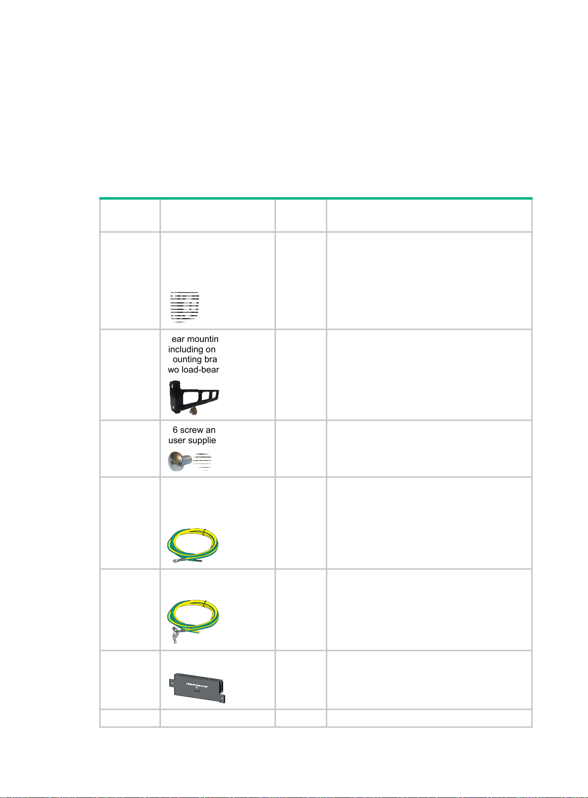
Installation accessories
All the installation accessories except M6 screws and floating nuts, the HPE X721 power to port fan
tray, PSR150/PSR150-A1 (JD362A/JD362B) AC power supplies, and the PSR150-D/PSR150-D1
(JD366A/JD366B) DC power supplies are provided with the switch.
Table 4 Installation accessories
Product
code
5066-0850
5190-0297
N/A
5185-9292
Description Quantity Applicable models
1 U four-hole mounting
bracket kit (including one
pair of mounting brackets
and eight M4 countersunk
screws)
Rear mounting bracket kit
(including one pair of
mounting brackets and
two load-bearing screws)
M6 screw and floating nut
(user supplied)
Grounding cable
(tin-plated at one end and
with a ring terminal at the
other end)
1 kit All HPE 5510 HI switches
1 kit
As
required
1
• HPE 5510 24G PoE+ 4SFP+ 1-slot HI
• HPE 5510 48G PoE+ 4SFP+ 1-slot HI
All HPE 5510 HI switches
• HPE 5510 24G 4SFP+ HI
• HPE 5510 48G 4SFP+ HI
• HPE 5510 24G SFP 4SFP+ HI
Grounding cable (with ring
terminals at both ends)
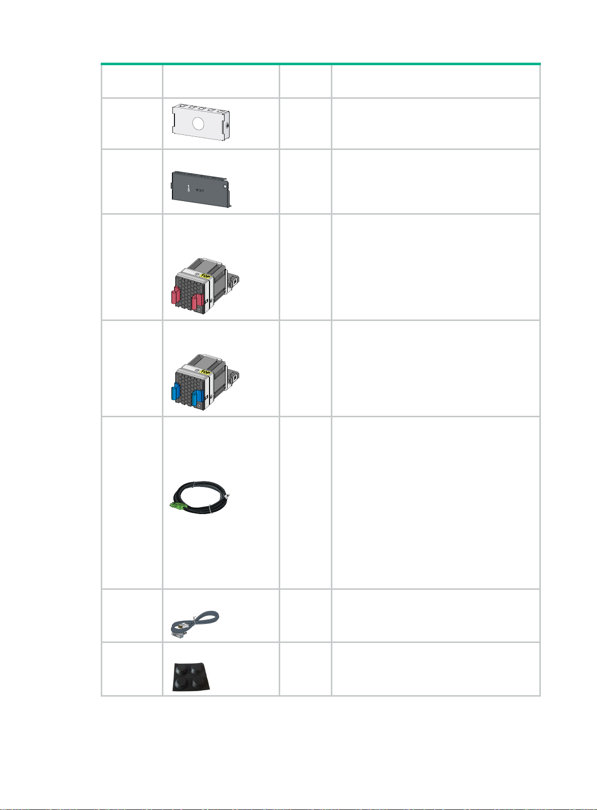
5185-9408
Power supply filler panel
5185-8503
5190-1774 Power supply filler panel 1
1
1
4
• HPE 5510 24G PoE+ 4SFP+ HI
• HPE 5510 48G PoE+ 4SFP+ HI
• HPE 5510 24G 4SFP+ HI
• HPE 5510 48G 4SFP+ HI
• HPE 5510 24G SFP 4SFP+ HI
• HPE 5510 24G PoE+ 4SFP+ HI
Page 10
•
Product
code
5190-0296
5060-0174
Description Quantity Applicable models
HPE 5510 48G PoE+ 4SFP+ HI
Interface card filler panel
1 All HPE 5510 HI switches
HPE X722 port to power
fan tray (already installed
on the switch)
2 All HPE 5510 HI switches
HPE X721 power to port
fan tray (order as required)
5060-0175
5185-9443
5080-0120
5184-6719
DC power cord (supplied
with the
PSR150-D/PSR150-D1
(JD366A/JD366B) DC
power supply)
The power cord color code
scheme is for illustration
only. The cable delivered
for your country or region
might use a different color
scheme.
Console cable
Rubber feet
2 All HPE 5510 HI switches
1
PSR150-D/PSR150-D1(JD366A/JD366B) DC
power supply
1 All HPE 5510 HI switches
5184-7298
4 All HPE 5510 HI switches
5
Page 11
Installing the switch
CAUTION:
Keep the tamper-proof seal on a mounting screw on the chassis cover intact, and if you want to open
the chassis, contact HPE for permission. Otherwise, HPE shall not be liable for any consequence.
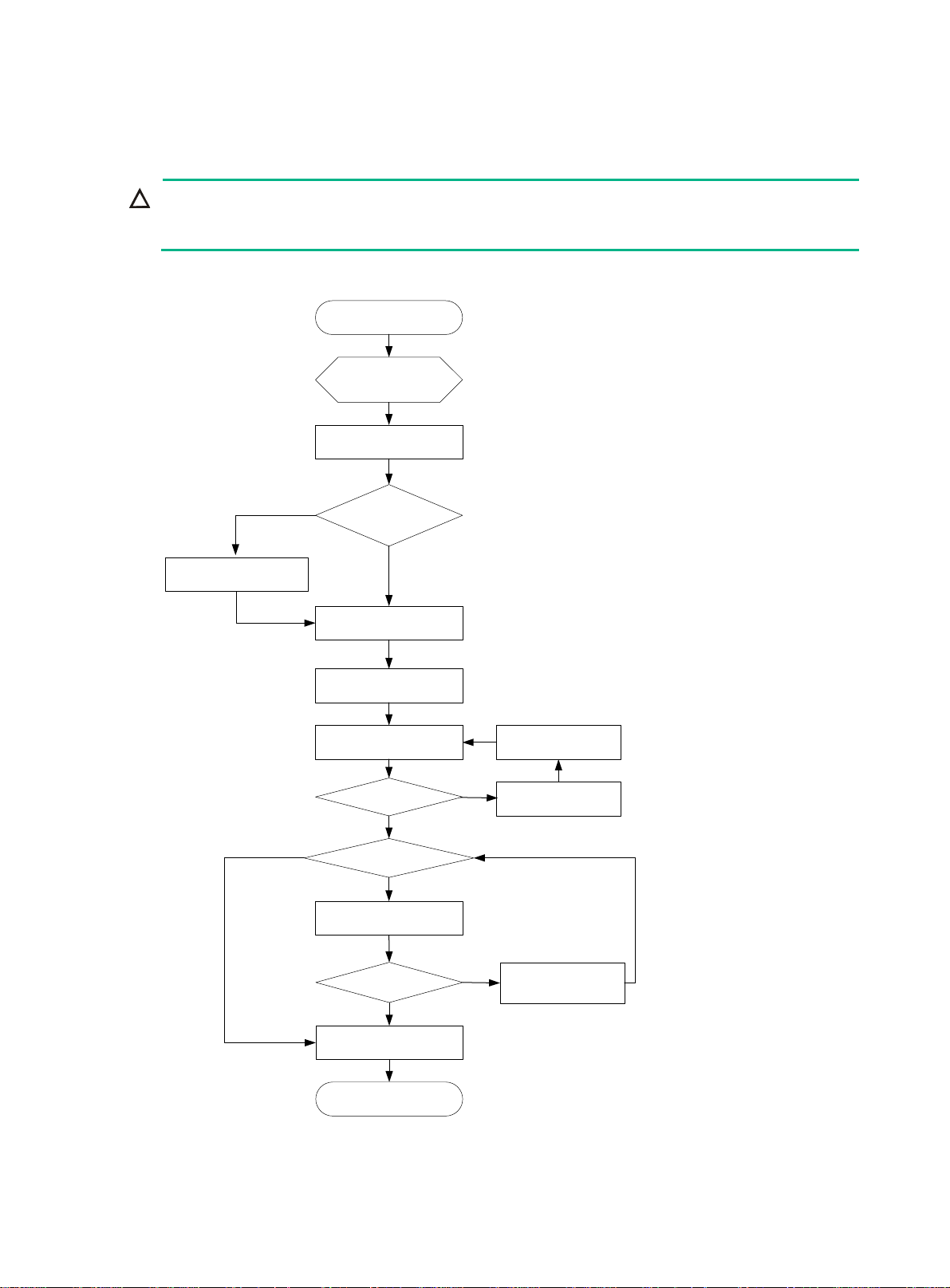
Figure 1 Hardware installation flow
Start
Install the switch
Ground the switch
Yes
Select and install power
supplies
No
Hot-swap power
supplies?
No
Connect power cords
Verify the installation
Turn on the circuit breaker
Operating correctly?
Yes
Hot-swap cards?
Yes
Install interface cards
Troubleshoot the switch
No
Turn off the circuit
breaker
Operating correctly?
Yes
Install transceiver modules
and cables
End
No
Troubleshoot the switch
6
Page 12

Installing the switch in a 19-inch rack
Installation accessories
Table 5 Installation accessories for the HPE 5510 HI switches
Installat
Chassis
• HPE 5510 24G 4SFP+
HI
• HPE 5510 48G 4SFP+
HI
• HPE 5510 24G SFP
4SFP+ HI
ion
access
ories
Front
mounting
bracket
kit
Installation requirements
The mounting bracket kit can be
installed on the port side, power
supply side, or the mid-mounting
position.
Installation
procedure
See "Rack-mounting by
usin
g front mounting
brackets."
Front
mounting
bracket
kit
• HPE 5510 24G PoE+
4SFP+ HI
• HPE 5510 48G PoE+
4SFP+ HI
Front and
rear
mounting
bracket
kits
Figure 2 Rack-mounting procedure (1)
The front mounting bracket kit must
be installed on the mid-mounting
position.
• The mounting bracket kit can be
installed on the port side or
power supply side.
• Install the rear mounting
brackets according to the rack
depth.
{ If the rack depth is in the
range of 429 to 595 mm
(16.89 to 23.43 in), orient
the bracket with the wide
flange inside the rack.
{ If the rack depth is in the
range of 274 to 440 mm
(10.79 to 17.32 in) and the
distance from the rear rack
posts to the inner surface of
the cabinet door is longer
than 153 mm (6.02 in),
orient the bracket with the
wide flange outside the
rack.
See "Rack-mounting by
using front mounting
brackets."
See "Rack-mounting by
g front and rear
usin
mounting brackets
(HPE 5510 24G PoE+
4SFP+ HI and HPE
5510 48G PoE+ 4SFP+
HI)."
Figure 3 Rack-mounting procedure (2)
7
Page 13

NOTE:
If a rack shelf is available, you can put the switch on the rack shelf, slide the switch to an appropriate
location, and attach the switch to the rack by using the mounting brackets.
Mounting bracket kits
Table 6 Mounting bracket kits for the HPE 5510 HI switches
HPE 5510 24G SFP 4SFP+
HI
Mounting bracket kits
HPE 5510 24G 4SFP+ HI
HPE 5510 48G 4SFP+ HI
Front mounting bracket kit Provided Provided
Rear mounting bracket kit Not required Provided
Chassis rail and slide rail Not required Not required
Grounding cable Provided Provided
HPE 5510 24G PoE+ 4SFP+
HI
HPE 5510 48G PoE+ 4SFP+
HI
Figure 4 Front mounting bracket kit
(1) Hole for attaching the bracket to the switch
chassis
(2) Hole for attaching the bracket to a rack
Figure 5 Rear mounting bracket kit and load-bearing screw
(1) Hole for attaching the bracket to a rack (2) Load-bearing screw
8
Page 14

Rack-mounting by using front mounting brackets
This task requires two people.
To install the switch in a 19-inch rack by using the front mounting brackets:
1. Wear an ESD wrist strap and make sure it makes good skin contact and is reliably grounded.
2. Determine the mounting position on the switch for the front mounting brackets.
You can install the front mounting brackets at one of the following positions:
{ HPE 5510 24G SFP 4SFP+ HI, HPE 5510 24G 4SFP+ HI, and HPE 5510 48G 4SFP+ HI
switches—Port side, power supply side, or mid-mounting position.
{ HPE 5510 24G PoE+ 4SFP+ HI and HPE 5510 48G PoE+ 4SFP+ HI
switches—Mid-mounting position.
3. Attach the front mounting brackets to the chassis:
a. Unpack the front mounting brackets and the M4 screws (supplied with the switch) for
attaching the brackets to the switch chassis.
b. Align the round holes in the wide flange of one front mounting bracket with the screw holes
in the chassis.
c. Use M4 screws to attach the mounting bracket to the chassis.
d. Repeat the proceeding two steps to attach the other mounting bracket to the chassis.
Figure 6 Attaching the front mounting bracket to the port side
Figure 7 Attaching the front mounting bracket to the power supply side
9
Page 15

Figure 8 Attaching the front mounting bracket to the mid-mounting position
4. Mount the chassis in the rack:
a. One person supports the chassis bottom with one hand, holds the front part of the chassis
with the other hand, and pushes the chassis into the rack gently
b. The other person uses M6 screws and cage nuts (user supplied) to attach the switch to the
rack.
Figure 9 Mounting the switch in the rack (front mounting brackets at the port side)
10
Page 16

Figure 10 Mounting the switch in the rack (front mounting brackets at the power supply
side)
Figure 11 Mounting the switch in the rack (front mounting brackets at the mid-mounting
position)
11
Page 17

Rack-mounting by using front and rear mounting brackets (HPE 5510 24G PoE+ 4SFP+ HI and HPE 5510 48G PoE+ 4SFP+ HI)
This mounting method is applicable to only the HPE 5510 24G PoE+ 4SFP+ HI and HPE 5510 48G
PoE+ 4SFP+ HI switches. You can install the front mounting brackets at the port-side or power-side
mounting position as needed. The following takes port-side mounting as an example. The
power-side mounting is similar.
This task requires two people.
To install the switch in a 19-inch rack by using the front and rear mounting brackets:
1. Wear an ESD wrist strap and make sure it makes good skin contact and is reliably grounded.
2. Attach the front mounting brackets and load-bearing screws to the chassis:
a. Unpack the front mounting brackets and the M4 screws for attaching the brackets to the
switch chassis.
b. Align the round holes in the wide flange of one front mounting bracket with the screw holes
in the port-side mounting position on one side of the chassis (see Figure 12).
c. Use M4 screws (supplied with the switch) to attach the mounting bracket to the chassis.
d. Repeat the proceeding two steps to attach the other mounting bracket to the chassis.
e. Unpack the load-bearing screws.
f. Install the load-bearing screws in one of the load-bearing screw mounting positions on both
sides of the chassis (see Figure 12).
Figure 12 Attaching the front mounting brackets and load-bearing screws to the chassis
3. Attach the rear mounting brackets to the rack:
a. Unpack the rear mounting brackets.
b. Install cage nuts (user-supplied) in the mounting holes in the rear rack posts.
c. Attach the rear mounting brackets to the rear posts with M6 screws (user supplied), as
shown in Figure 13 a
Do not fully tighten the M6 screws before mounting the switch in the rack.
nd Figure 14.
12
Page 18

Figure 13 Attaching the rear mounting brackets to the rack with the wide flange inside
the rack
Figure 14 Attaching the rear mounting brackets to the rack with the wide flange outside
the rack
4. Mount the switch chassis in the rack:
a. One person supports the chassis bottom with one hand, holds the front part of the chassis
with the other hand, and pushes the chassis into the rack gently.
Make sure the load-bearing screws closely contact with the upper edges of the rear
mounting brackets, as shown in Figure 15 and Figure 16.
13
Page 19

b. The other person aligns the oval holes in the front brackets with the mounting holes in the
front rack posts, and attaches the front mounting brackets with M6 screws (user supplied) to
the front rack posts.
Tighten the screws and make sure the front and rear mounting brackets have securely
attached the switch to the rack.
Figure 15 Mounting the switch in the rack (with the wide flange of the mounting brackets
inside the rack)
Figure 16 Mounting the switch in the rack (with the wide flange of the mounting brackets
outside the rack)
14
Page 20

Mounting the switch on a workbench
IMPORTANT:
• Ensure good ventilation and 10 cm (3.9 in) of clearance around the chassis for heat dissipation.
• Avoid placing heavy objects on the switch.
To mount the switch on a workbench:
1. Verify that the workbench is sturdy and reliably grounded.
2. Place the switch with bottom up, and clean the round holes in the chassis bottom with dry cloth.
3. Attach the rubber feet to the four round holes in the chassis bottom.
4. Place the switch with upside up on the workbench.
Grounding the switch
WARNING!
Correctly connecting the switch grounding cable is crucial to lightning protection and EMI protection.
The power input end of the switch has a noise filter, whose central ground is directly connected to the
chassis to form the chassis ground (commonly known as PGND). You must securely connect this
chassis ground to the earth so the faradism and leakage electricity can be safely released to the
earth to minimize EMI susceptibility of the switch.
You can ground the switch in one of the following ways, depending on the grounding conditions
available at the installation site:
• Grounding the switch with a grounding strip
• Grounding the switch with a grounding conductor buried in the earth ground
• Grounding the switch by using the AC power cord
NOTE:
The power and grounding terminals in this section are for illustration only.
Grounding the switch with a grounding strip
WARNING!
Connect the grounding cable to the grounding system in the equipment room. Do not connect it to a
fire main or lightning rod.
If a grounding strip is available at the installation site, connect the grounding cable to the grounding
strip.
Connecting the grounding cable to the chassis
1. Remove the grounding screw from the rear panel of the switch chassis.
2. Use the grounding screw to attach the ring terminal of the grounding cable to the grounding
screw hole.
3. Verify that the grounding cable has been securely connected to the rear grounding point.
15
Page 21

Figure 17 Connecting the grounding cable to the chassis
(1) Grounding screw (2) Ring terminal
(3) Grounding sign (4) Grounding hole
(5) Grounding cable
Connecting the grounding cable to a grounding strip (for the HPE 5510 24G PoE+ 4SFP+ HI and HPE 5510 48G PoE+ 4SFP+ HI switches)
1. Remove the hex nut of a grounding post on the grounding strip.
2. Cut the grounding cable to a length required for connecting to the grounding strip.
3. Attach a ring terminal to the grounding cable:
a. Use a wire stripper to strip 5 mm (0.20 in) of insulation off the end of the grounding cable.
b. Slide the heat-shrink tubing onto the cable and insert the bare metal part into the end of the
ring terminal.
c. Use a crimper to secure the metal part of the cable to the ring terminal.
d. Slide the heat-shrink tubing down the cable until the tube covers the joint.
e. Use a heat gun to shrink the tubing around the cable.
Figure 18 Attaching a ring terminal to the grounding cable
4. Connect the ring terminal to the grounding post of the grounding strip, and fasten it with the
removed hex nut.
16
Page 22

Figure 19 Connecting the grounding cable to a grounding strip
1
4 3
(1) Grounding post (2) Grounding strip
(3) Grounding cable (4) Hex nut
2
Connecting the grounding cable to a grounding strip (for the HPE 5510 24G 4SFP+ HI, HPE 5510 48G 4SFP+ HI, and HPE 5510 24G SFP 4SFP+ HI switches)
1. Remove the hex nut of a grounding post on the grounding strip.
2. Cut the grounding cable to a length required for connecting to the grounding strip.
3. Use a wire stripper to peel 20 mm (0.79 in) of insulation sheath off the grounding cable end.
4. Use the needle-nose pliers to bend the bare wire.
5. Hook the grounding cable to the post on the grounding strip, and use the hex nut to secure the
cable to the post.
Figure 20 Connecting the grounding cable to a grounding strip
1 2
34
(1) Grounding post (2) Grounding strip
(3) Grounding cable (4) Hex nut
Grounding the switch with a grounding conductor buried in the earth ground
If the installation site has no grounding strips, but earth ground is available, hammer a 0.5 m (1.64 ft)
or longer angle iron or steel tube into the earth ground to serve as a grounding conductor.
The dimensions of the angle iron must be a minimum of 50 × 50 × 5 mm (1.97 × 1.97 × 0.20 in). The
steel tube must be zinc-coated and its wall thickness must be a minimum of 3.5 mm (0.14 in).
Weld the yellow-green grounding cable to the angel iron or steel tube and treat the joint for corrosion
protection.
17
Page 23

Figure 21 Grounding the switch by burying the grounding conductor into the earth ground
(1) Grounding screw (2) Chassis rear panel (3) Grounding cable
(4) Earth (5) Joint (6) Grounding conductor
Grounding the switch by using the AC power cord
If the installation site has no grounding strips or earth ground, you can ground an AC-powered switch
through the PE wire of the power cord. Make sure:
• The power cord has a PE terminal.
• The ground contact in the power outlet is securely connected to the ground in the power
distribution room or on the AC transformer side.
• The power cord is securely connected to the power outlet.
NOTE:
• If the ground contact in the power outlet is not connected to the ground, report the problem and
reconstruct the grounding system.
• As a best practice to guarantee the grounding effect, use the grounding cable provided with the
switch to connect to the grounding strip in the equipment room.
Installing/removing a power supply
WARNING!
In power redundancy mode, you can replace a power supply without powering off the switch but you
must strictly follow the installation and procedures in Figure 22 an
injury or damage to the switch.
d Figure 23 to avoid any bodily
CAUTION:
Provide a circuit breaker for each power supply.
18
Page 24

Figure 22 Installation procedure
Figure 23 Removal procedure
Turn off the circuit
breaker
Disconnect the power
cord
Remove the power
supply
Installing a PSR150(JD362A, JD362B, JD366A, or JD366B) power supply
CAUTION:
To prevent damage to the power supply or the connectors on the backplane, insert the power supply
gently. If you encounter a hard resistance when inserting the power supply, pull out the power supply
and insert it again.
For the PSR150-A/PSR150-A1 (JD362A/JD362B) and PSR150-D/PSR150-D1 (JD366A/JD366B)
power supplies, the installation and removal procedures are the same. The following takes the
PSR150-A1 (JD362B) power supply as an example.
To install a power supply:
1. Wear an ESD wrist strap and make sure it makes good skin contact and is reliably grounded.
2. Remove the filler panel from the target power supply slot as follows:
a. Remove the screws on the filler panel.
b. Use a flathead screwdriver to remove the filler panel.
Figure 24 Removing the filler panel
3. Unpack the power supply and verify that the power supply model is correct.
4. Correctly orient the power supply with the power supply slot (use the letters on the power supply
faceplate for orientation), grasp the handle of the power supply with one hand and support its
19
Page 25

bottom with the other, and slide the power supply slowly along the guide rails into the slot (see
callout 1 in Figure 25).
5. Fasten the captive screws on the power supply with a Phillips screwdriver to secure the power
supply in the chassis (see callout 2 in Figure 25). If the ca
verify the installation of the power supply.
6. Install the filler panel over the empty power supply slot to prevent dust and ensure good
ventilation if you install only one power supply.
Figure 25 Installing a PSR150-A1 (JD362B) power supply
ptive screw cannot be tightly fastened,
Removing a PSR150(JD362A, JD362B, JD366A, or JD366B) power supply
1. Wear an ESD wrist strap and make sure it makes good skin contact and is reliably grounded.
2. Disconnect the power cord.
3. Loosen the captive screws of the power supply with a Phillips screwdriver until they are
completely disengaged.
4. Grasp the handle of the power supply with one hand and pull it out a little, support the bottom
with the other hand, and pull the power supply slowly along the guide rails out of the slot.
Put away the removed power supply in an antistatic bag or the power supply package bag for
future use.
5. Install the filler panel to prevent dust and ensure good ventilation if no power supply is installed
in the slot.
Installing a PSR720-56A/PSR1110-56A (JG544A/JG545A) power supply
CAUTION:
To prevent damage to the power supply or the connectors on the backplane, insert the power supply
gently. If you encounter a hard resistance when inserting the power supply, pull out the power supply
and insert it again.
For the PSR720-56A (JG544A) and PSR1110-56A (JG545A) power supplies, the installation and
removal procedures are the same. The following takes the PSR720-56A (JG544A) power supply as
an example.
To install a power supply:
1. Wear an ESD wrist strap and make sure it makes good skin contact and is reliably grounded.
2. Remove the filler panel from the target power supply slot, as shown in Figure 26.
20
Page 26

Figure 26 Removing the filler panel
3. Unpack the power supply and verify that the power supply model is correct.
Put away the packaging box and packaging bag of the power supply for future use.
4. Correctly orient the power supply with the power supply slot (use the letters on the power supply
faceplate for orientation), grasp the handle of the power supply with one hand and support its
bottom with the other, and slide the power supply slowly along the guide rails into the slot until
you hear that the latch of the power supply clicks into the slot.
When you insert the power supply into the slot, you can do that through slight inertia so that the
terminals of the power supply can have good contact with the backplane.
The PSR1110-56A (JG545A) power supply adds 64 mm (2.52 in) to the depth of the switch, as
shown in Figure 27.
5. Install the filler panel ove
ventilation if you install only one power supply.
r the empty power supply slot to prevent dust and ensure good
Figure 27 PSR1110-56A (JG545A) in the chassis
Removing a PSR720-56A/PSR1110-56A (JG544A/JG545A) power supply
1. Wear an ESD wrist strap and make sure it makes good skin contact and is reliably grounded.
21
Page 27

2. Disconnect the power cord.
3. Press the latch towards the handle, and pull the power supply along the guide rails until it is
part-way out.
4. Grasp the handle of the power supply with one hand, support the bottom with the other hand,
and pull the power supply slowly along the guide rails out of the slot.
Put away the removed power supply in an antistatic bag or the power supply package bag for
future use.
5. Install the filler panel to prevent dust and ensure good ventilation if no power supply is installed
in the slot.
Figure 28 Removing the power supply
1
2
Connecting the power cord
CAUTION:
• The AC power cord for the PSR150-A/PSR150-A1 (JD362A/JD362B) uses C13 connector, while
the AC power cord for the PSR720-56A (JG544A)/PSR1110-56A (JG545A) uses
high-temperature C15 connector. Do not mix them.
• Provide a circuit breaker for each power supply and make sure the circuit breaker is off before
installation.
Table 7 Power cord connection procedures at a glance
Power supply Connection procedure reference
• PSR150-D(JD366A)
• PSR150-D1(JD366B)
(External RPS power supply: RPS800-A or
RPS1600-A)
• PSR720-56A (JG544A)
• PSR1110-56A (JG545A)
• PSR150-A/PSR150-A1(JD362A/JD362B)
Connecting the PSR150-D/PSR150-D1
(JD366A/JD366B) power supply
Connecting the PSR720-56A
(JG544A)/PSR1110-56A (JG545A)/PSR150-A
(JD362A)/PSR150-A1 (JD362B) power supply
22
Page 28

Connecting the PSR150-D/PSR150-D1 (JD366A/JD366B) power supply
WARNING!
• HPE DC power cords are required if the –48 VDC power source is used. RPS power cords are
required if the RPS power source is used.
• The power cord color code scheme in Figure 29 is for
your country or region might use a different color scheme. When you connect a power cord,
always identify the polarity symbol on its wires.
To connect the PSR150-D/PSR150-D1 (JD366A/JD366B) power supply:
1. Wear an ESD wrist strap and make sure it makes good skin contact and is reliably grounded.
2. Insert the DC connector into the DC power receptacle (see callout 1 in Figure 29).
The conne
connector is correctly oriented.
3. Use a flat-blade screwdriver to fasten the two screws on the DC plug to secure the plug to the
DC receptacle (see callout 2 in Figure 29).
4. Connect the other ends of the wires to the –48 VDC power source wiring terminals, with the
negative wire (– or L–) to the negative terminal (–) and the positive wire (+ or M/N) to the
positive terminal (+).
ctor of the DC power cord and the DC power receptacle are foolproof. Make sure the
illustration only. The cable delivered for
Figure 29 Connecting the PSR150-D1 (JD366B) power supply
1
2
Connecting the PSR720-56A (JG544A)/PSR1110-56A (JG545A)/PSR150-A (JD362A)/PSR150-A1 (JD362B) power supply
The procedure is similar for connecting a PSR720-56A (JG544A), PSR1110-56A (JG545A), or
PSR150-A/PSR150-A1 (JD362A/JD362B) power supply. The following uses the PSR720-56A
(JG544A) power supply as an example.
To connect the PSR720-56A (JG544A) power supply:
1. Wear an ESD wrist strap and make sure it makes good skin contact and is reliably grounded.
23
Page 29

2. Plug the female connector end of the AC power cord into the AC input socket of the power
supply (see callout 1 in Figure 30).
3. Use a cable tie to secure the power cord to the handle of the power supply (see callout 2 and
callout 3 in Figure 30).
4. Connect the other end of the AC power cord to an AC power outlet.
Figure 30 Connecting a PSR720-56A (JG544A) power supply
Installing/removing an interface card
CAUTION:
• Do not touch the surface-mounted components on an interface card directly with your hands.
• Do not use excessive force during the installation or removal procedure.
• Install a filler panel over an empty interface card slot.
The switch has an interface card slot and supports hot swapping of an interface card. For the
interface cards available for the switches, see "Appendix B FRUs and compatibility matrixes."
This se
installing and removing an interface card.
Installing an interface card
1. Wear an ESD wrist strap and make sure it makes good skin contact and is reliably grounded.
2. Remove the filler panel from the target interface card slot as follows:
ction uses the LSWM2SP2PM interface card as an example to describe the procedures of
a. Remove the screw on the filler panel.
b. Use a flathead screwdriver to remove the filler panel.
Keep the filler panel for future use.
24
Page 30

Figure 31 Removing the filler panel over an interface card slot
3. Unpack the interface card.
4. (Optional.) Rotate out the ejector lever.
5. Gently push the interface card into the slot along the guide rails until the interface card has good
contact with the switch chassis
6. (Optional.) Rotate in the ejector lever.
7. Tighten the captive screws with a Phillips screwdriver to secure the interface card in the slot.
25
Page 31

Figure 32 Installing an interface card with an ejector lever
Removing an interface card
1. Wear an ESD wrist strap and make sure it makes good skin contact and is reliably grounded.
2. Use a Phillips screwdriver to completely loosen the captive screw on the interface card.
3. Rotate rightward the ejector lever on the interface card.
4. Pull the interface card out of the chassis gently along the guide rails.
Verifying the installation
After you complete the installation, verify that:
• There is enough space for heat dissipation around the switch, and the rack or workbench is
stable.
• The grounding cable is securely connected.
• The correct power source is used.
26
Page 32

• The power cords are correctly connected.
• All the interface cables are cabled indoors. If any cable is routed outdoors, verify that the socket
strip with lightning protection and lightning arresters for network ports have been correctly
connected.
27
Page 33

Accessing the switch for the first time
Setting up the configuration environment
You can access the HPE 5510 HI switch through the serial console port or the mini USB console port.
As a best practice, use the serial console port to access the switch. To access the switch through the
mini USB console port, you need to prepare a mini USB console cable.
Only the mini USB console port takes effect if you connect both the serial console port and mini USB
console port.
Figure 33 Connecting the console port to a PC
Connecting the console cable
A console cable is an 8-core shielded cable, with a crimped RJ-45 connector at one end for
connecting to the console port of the switch, and a DB-9 female connector at the other end for
connecting to the serial port on the console terminal.
Figure 34 Console cable
A side
Pin 9
A
Pin 1
Table 8 Console port signaling and pinout
Main label
8
1
B side
B
RJ-45 Signal DB-9 Signal
1 RTS 8 CTS
2 DTR 6 DSR
28
Page 34

RJ-45 Signal DB-9 Signal
3 TXD 2 RXD
4 SG 5 SG
5 SG 5 SG
6 RXD 3 TXD
7 DSR 4 DTR
8 CTS 7 RTS
To connect a configuration terminal (for example, a PC) to the switch:
1. Plug the DB-9 female connector of the console cable to the serial port of the PC.
2. Connect the RJ-45 connector to the console port of the switch.
NOTE:
• Identify the mark on the console port and make sure you are connecting to the correct port.
• The serial ports on PCs do not support hot swapping. To connect a PC to an operating switch, first
connect the PC end. To disconnect a PC from an operating switch, first disconnect the switch end.
Connecting the Mini USB console cable
A Mini USB console cable has a Mini USB Type B connector at one end to connect to the Mini USB
console port of the switch, and a standard USB Type A connector at the other end to connect to the
USB port on the PC.
To connect to the PC through the Mini USB console cable:
1. Connect the standard USB Type A connector to the USB port of the PC.
2. Connect the Mini USB Type B connector to the Mini USB console port of the switch.
3. Click the following link, or copy it to the address bar on the browser to log in to download page
of the USB console driver, and download the driver.
http://www.exar.com/connectivity/uart-and-b
4. Select a driver program according to the operating system you use:
{ XR21V1410_XR21B1411_Windows_Ver1840_x86_Installer.EXE—32-bit operating
system.
{ XR21V1410_XR21B1411_Windows_Ver1840_x64_Installer.EXE—64-bit operating
system.
5. Click Next on the installation wizard.
ridging-solutions/usb-uarts/xr21v1410
29
 Loading...