

Page 1

HPE FlexNetwork 5130 HI Switch Series
High Availability
Configuration Guide
Part number: 5200-3603
Software version: Release 13xx
Document version: 6W100-20170315
Page 2

© Copyright 2015, 2017 Hewlett Packard Enterprise Development LP
The information contained herein is subject to change without notice. The only warranties for Hewlett Packard
Enterprise products and services are set forth in the express warranty statements acco mpanying such
products and services. Nothing herein should be construe d as constituting an additional warranty. Hewlett
Packard Enterprise shall not be liable for technical or editorial errors or omissions co ntained herein.
Confidential computer software. V alid license from Hewlett Packard Enterprise required for possession, use, or
copying. Consistent with FAR 12.211 and 12.212, Commercial Computer Software, Computer Software
Documentation, and T e chnical Data for Commercial Items are licensed to the U.S. Government under vendor’s
standard commercial license.
Links to third-party websites take you outside the Hewlett Packard Enterprise website. Hewlett Packard
Enterprise has no control over and is not responsible for information outside the Hewlett Packard Enterprise
website.
Acknowledgments
Intel®, Itanium®, Pentium®, Intel Inside®, and the Intel Inside logo are trademarks of Intel Corporation in the
United States and other countries.
Microsoft® and Windows® are either registered trademarks or trademarks of Microsoft Corporation in the
United States and/or other countries.
Adobe® and Acrobat® are trademarks of Adobe Systems In corporated.
Java and Oracle are registered trademarks of Oracle and/or its affiliates.
UNIX® is a registered trademark of The Open Group.
Page 3

Contents
Configuring CFD ·············································································· 1
Overview ·································································································································· 1
Basic CFD concepts ············································································································ 1
CFD functions ····················································································································· 3
EAIS ································································································································· 5
Protocols and standards ······································································································· 5
CFD configuration task list ··········································································································· 5
Configuring basic CFD settings ····································································································· 6
Enabling CFD ····················································································································· 6
Configuring Ethernet service instances ···················································································· 6
Configuring MEPs ··············································································································· 7
Configuring MIP auto-generation rules ····················································································· 7
Configuring CFD functions ··········································································································· 8
Configuration prerequisites ···································································································· 8
Configuring CC ··················································································································· 8
Configuring LB ···················································································································· 9
Configuring LT ···················································································································· 9
Configuring AIS ··················································································································· 9
Configuring LM ················································································································· 10
Configuring one-way DM ····································································································· 10
Configuring two-way DM ····································································································· 11
Configuring TST ················································································································ 11
Configuring EAIS ····················································································································· 11
Displaying and maintaining CFD ································································································· 12
CFD configuration example ········································································································ 13
Configuring DLDP ·········································································· 18
Overview ································································································································ 18
Basic concepts ················································································································· 19
How DLDP works ·············································································································· 20
Configuration restrictions and guidelines ······················································································· 22
DLDP configuration task list ······································································································· 22
Enabling DLDP ························································································································ 22
Setting the interval to send advertisement packets ·········································································· 23
Setting the DelayDown timer ······································································································ 23
Setting the port shutdown mode ·································································································· 23
Configuring DLDP authentication ································································································· 24
Displaying and maintaining DLDP ································································································ 24
DLDP configuration examples ····································································································· 25
Configuring the auto port shutdown mode ··············································································· 25
Configuring the manual port shutdown mode ··········································································· 28
Configuring the hybrid port shutdown mode ············································································ 31
Configuring RRPP ·········································································· 36
Overview ································································································································ 36
Basic RRPP concepts ········································································································ 36
RRPPDUs ······················································································································· 38
RRPP timers ···················································································································· 39
How RRPP works ·············································································································· 39
Typical RRPP networking ···································································································· 40
Protocols and standards ····································································································· 43
RRPP configuration task list ······································································································· 44
Creating an RRPP domain ········································································································· 44
Configuring control VLANs ········································································································· 44
Configuring protected VLANs ····································································································· 45
Configuring RRPP rings ············································································································ 46
Configuring RRPP ports ······································································································ 46
i
Page 4

Configuring RRPP nodes ···································································································· 47
Activating an RRPP domain ······································································································· 48
Configuring RRPP timers ··········································································································· 49
Configuring an RRPP ring group ································································································· 49
Enabling SNMP notifications for RRPP ························································································· 50
Displaying and maintaining RRPP ······························································································· 50
RRPP configuration examples ···································································································· 50
Single ring configuration example ························································································· 50
Intersecting ring configuration example ·················································································· 53
Dual-homed rings configuration example ················································································ 59
Load-balanced intersecting-ring configuration example ······························································ 69
Troubleshooting RRPP ·············································································································· 79
Configuring ERPS ·········································································· 80
Overview ································································································································ 80
ERPS structure ················································································································· 80
ERPS protocol packets ······································································································· 81
ERPS node states ············································································································· 82
ERPS timers ···················································································································· 82
ERPS operation mechanism ································································································ 83
ERPS network diagrams ····································································································· 85
Protocols and standards ····································································································· 87
ERPS configuration task list ······································································································· 87
Configuration prerequisites ········································································································ 88
Enabling ERPS globally ············································································································· 88
Enabling flush packet transparent transmission ·············································································· 89
Configuring an ERPS ring ·········································································································· 89
Enabling R-APS packets to carry the ring ID in the destination MAC address ········································ 89
Configuring ERPS ring member ports ··························································································· 89
Configuring ERPS ring member port attributes ········································································· 90
Configuring an ERPS ring member port ·················································································· 90
Configuring control VLANs ········································································································· 90
Configuring protected VLANs ····································································································· 91
Configuring the node role ··········································································································· 92
Enabling ERPS for an instance ··································································································· 92
Configuring R-APS packet levels ································································································· 93
Setting ERPS timers ················································································································· 93
Setting the non-revertive mode ··································································································· 93
Setting the MS mode ················································································································ 94
Setting the FS mode ················································································································· 94
Associating a ring with a subring ································································································· 94
Associating an ERPS ring member port with a track entry ································································· 94
Removing the MS mode and FS mode settings for an ERPS ring ······················································· 95
Displaying and maintaining ERPS ······························································································· 95
ERPS configuration examples ···································································································· 95
One-ring configuration example ···························································································· 95
One-subring configuration example ····················································································· 104
One-ring multi-instance load balancing configuration example ·················································· 117
Troubleshooting ERPS ············································································································ 127
Configuring Smart Link ·································································· 129
Overview ······························································································································ 129
Terminology ··················································································································· 130
How Smart Link works ······································································································ 130
Smart Link collaboration mechanisms ·················································································· 131
Smart Link configuration task list ······························································································· 132
Configuring a Smart Link device ································································································ 132
Configuration prerequisites ································································································ 132
Configuring protected VLANs for a smart link group ································································ 132
Configuring member ports for a smart link group ···································································· 133
Configuring a preemption mode for a smart link group ····························································· 134
Enabling the sending of flush messages ··············································································· 134
ii
Page 5

Configuring collaboration between Smart Link and Track ························································· 134
Configuring an associated device ······························································································ 135
Configuration prerequisites ································································································ 135
Enabling the receiving of flush messages ············································································· 135
Displaying and maintaining Smart Link ······················································································· 136
Smart Link configuration examples ···························································································· 136
Single smart link group configuration example ······································································· 136
Multiple smart link groups load sharing configuration example ·················································· 141
Smart Link and Track collaboration configuration example ······················································· 145
Configuring Monitor Link ································································ 151
Overview ······························································································································ 151
Configuration restrictions and guidelines ····················································································· 152
Monitor Link configuration task list ····························································································· 152
Enabling Monitor Link globally ·································································································· 152
Creating a monitor link group ···································································································· 152
Configuring monitor link group member interfaces ········································································· 153
Configuring the uplink interface threshold for triggering monitor link group state switchover ··················· 153
Configuring the switchover delay for the downlink interfaces in a monitor link group ····························· 154
Displaying and maintaining Monitor Link ····················································································· 154
Monitor Link configuration example ···························································································· 154
Configuring BFD ·········································································· 159
Overview ······························································································································ 159
BFD session establishment and termination ·········································································· 159
BFD session modes and operating modes ············································································ 159
Supported features ·········································································································· 160
Protocols and standards ··································································································· 160
Configuring BFD basic functions ······························································································· 160
Configuring echo packet mode ··························································································· 161
Configuring control packet mode ························································································ 161
Configuring a BFD template ····································································································· 163
Enabling SNMP notifications for BFD ························································································· 164
Displaying and maintaining BFD ································································································ 164
Configuring Track ········································································· 165
Overview ······························································································································ 165
Collaboration fundamentals ······························································································· 165
Collaboration application example ······················································································· 166
Track configuration task list ······································································································ 166
Associating the Track module with a detection module ··································································· 167
Associating Track with NQA ······························································································ 167
Associating Track with BFD ······························································································· 167
Associating Track with CFD ······························································································· 168
Associating Track with interface management ······································································· 168
Associating Track with route management ············································································ 169
Associating Track with LLDP ····························································································· 169
Associating the Track module with an application module ······························································· 170
Associating Track with static routing ···················································································· 170
Associating Track with PBR ······························································································· 171
Associating Track with Smart Link ······················································································· 172
Associating Track with EAA ······························································································· 172
Associating Track with ERPS ····························································································· 173
Displaying and maintaining track entries ····················································································· 174
Track configuration examples ··································································································· 174
Static routing-Track-NQA collaboration configuration example ·················································· 174
Static routing-Track-BFD collaboration configuration example ··················································· 178
Static routing-Track-LLDP collaboration configuration example ················································· 182
Smart Link-Track-CFD collaboration configuration example ······················································ 185
Configuring process placement ······················································· 186
Overview ······························································································································ 186
iii
Page 6

Process ························································································································· 186
1:N process redundancy ··································································································· 186
Process placement policy and optimization ··········································································· 186
Configuration restrictions and guidelines ····················································································· 187
Process placement configuration task list ···················································································· 187
Configuring process placement policy ························································································ 188
Configuring a location affinity ····························································································· 188
Configuring a location type affinity ······················································································· 188
Configuring a process affinity ····························································································· 189
Configuring a self affinity ··································································································· 189
Optimizing process placement ·································································································· 189
Displaying process placement ·································································································· 190
Document conventions and icons ···················································· 191
Conventions ························································································································· 191
Network topology icons ··········································································································· 192
Support and other resources ·························································· 193
Accessing Hewlett Packard Enterprise Support ············································································ 193
Accessing updates ················································································································· 193
Websites ······················································································································· 194
Customer self repair ········································································································· 194
Remote support ·············································································································· 194
Documentation feedback ·································································································· 194
Index ························································································· 196
iv
Page 7
Configuring CFD
Overview
Connectivity Fault Detection (CFD), which conforms to IEEE 802.1ag Connectivity Fault
Management (CFM) and ITU-T Y.1731, is an end-to-end per-VLAN link layer OAM mechanism. CFD
is used for link connectivity detection, fault verification, and fault location.
Basic CFD concepts
Maintenance domain
A maintenance domain (M D) defines the network or part of the network where CFD plays its role. An
MD is identified by its MD name.
To accurately locate faults, CFD introduces eight levels (from 0 to 7) to MDs. The bigger the number,
the higher the level and the larger the area covered. Domains can touch or nest (if the outer domai n
has a higher level than the nested one) but cannot intersect or overlap.
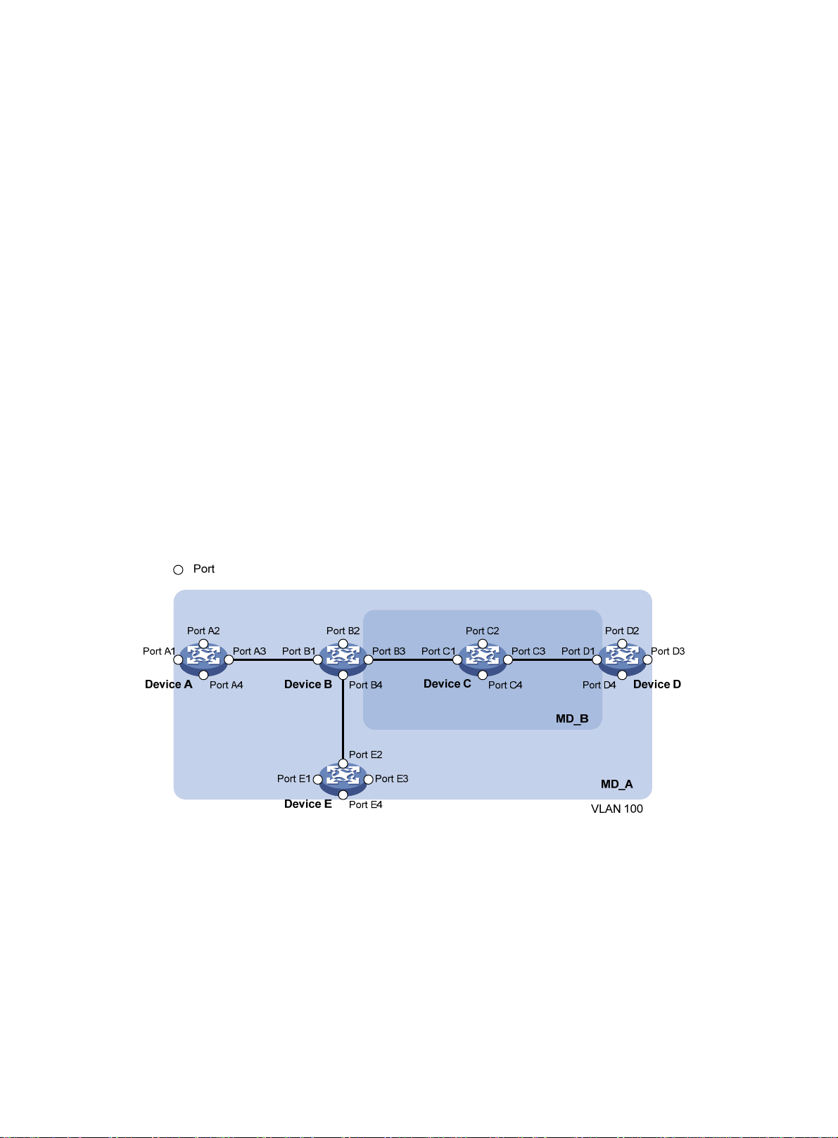
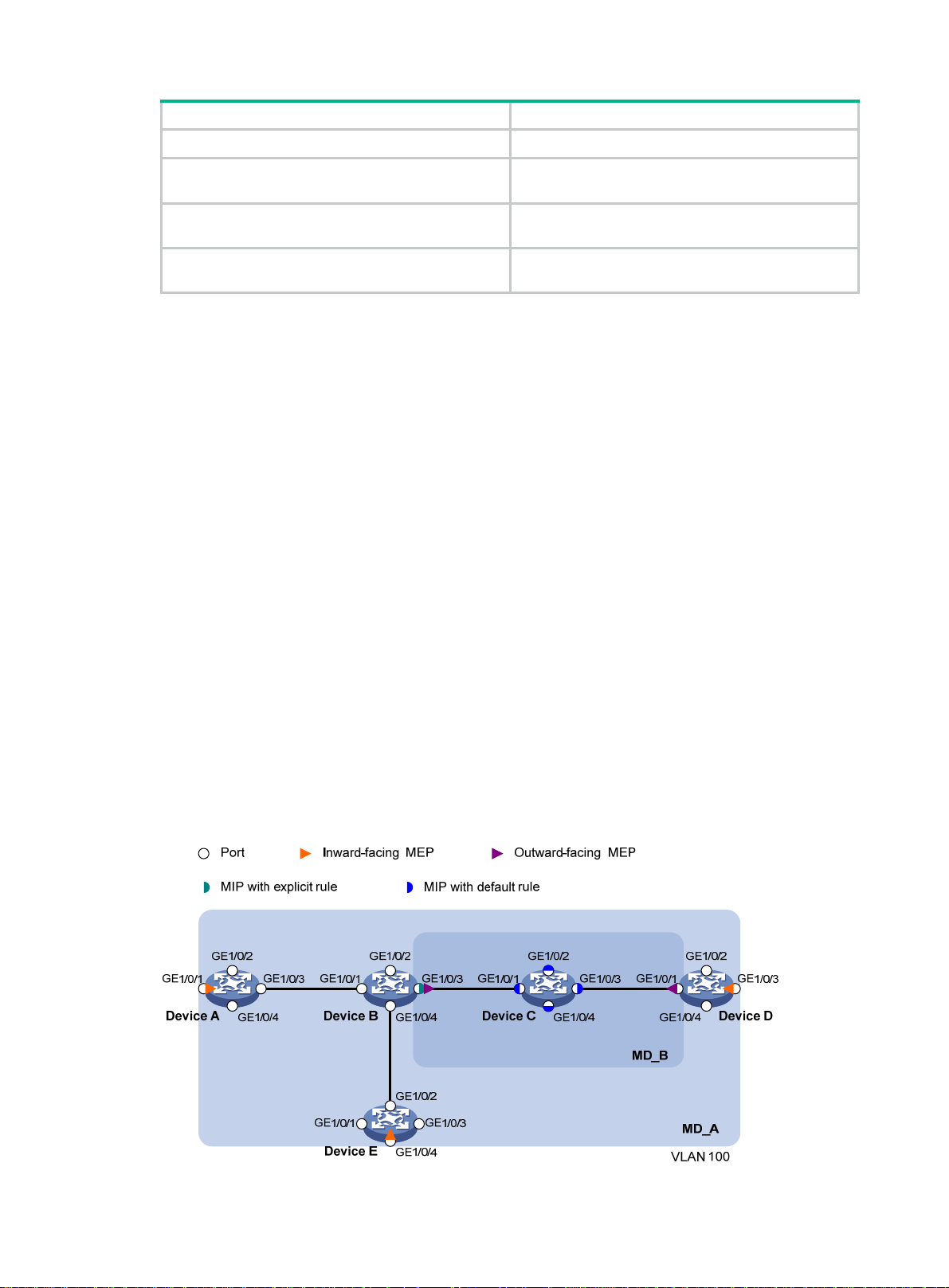
MD levels facilitate fault location and make fault location more accurate. As shown in Figure 1, MD_A
in light blue nests MD_B in dark blue. If a connectivity fault is detected at the boundary of MD_A, any
of the devices in MD_A, including Device A through Device E, might fail. If a connectivity fault is also
detected at the boundary of MD_B, the failure points can be any of Device B through Device D. If the
devices in MD_B can operate correctly, at least Device C is operational.
Figure 1 Two nested MDs
CFD exchanges messages and performs operations on a per-domain basis. By planning MDs
correctly in a network, you can use CFD to rapidly locate failure points.
Maintenance association
A maintenance association (MA) is a part of an MD. You can configure multiple MAs in an MD as
needed. An MA is identified by the MD name + MA name.
An MA serves the specified VLAN or no VLAN. An MA that serves a VLAN is considered to be
carrying VLAN attribute. An MA that serves no VLAN is considered to be carryin g no VLAN attribute.
An MP can receive packets sent by other MPs in the same MA. The level of an MA equals the level of
the MD that the MA belongs to.
1
Page 8
Maintenance point
An MP is configured on a port and bel on gs to an MA. MPs in clude the following types: maintenance
association end points (MEPs) and maintenance association intermediate points (MIPs).
• MEP
MEPs define the boundary of the MA. Each MEP is identified by a MEP ID.
The MA to which a MEP belongs defines the VLAN of packets sent by the MEP. The level of a
MEP equals the level of the MD to which the MEP belongs. The level of packets sent by a MEP
equals the level of the MEP.
The level of a MEP determines the levels of packets that the MEP can process. A MEP forwards
packets at a higher level and processes packet of its level or lower. The processing procedure
is specific to packets in the same VLAN. Packets of different VLANs are independent.
MEPs include inward-facing MEPs and outward-facing MEPs:
{ An outward-facing MEP sends packets to its host port.
{ An inward-facing MEP does not send packets to its host port. Rather, it sends packets to
other ports on the device.
• MIP
A MIP is internal to an MA. It cannot send CFD packets actively, but it can handle and respond
to CFD packets. By cooperating with MEPs, a MIP can perform a function similar to ping and
traceroute. A MIP forwards packets of a different level without any processing and only
processes packet of its level.
The MA to which a MIP belongs defines the VLAN of packets that the MIP can receive. The
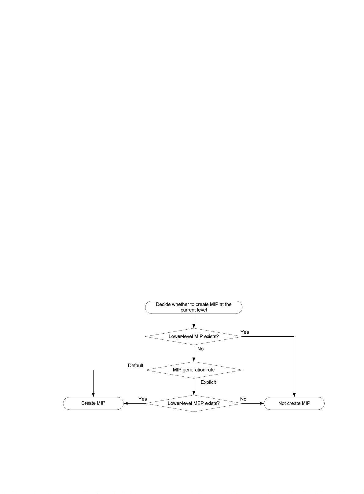
level of a MIP is defined by its generation rule and the MD to which the MIP belongs. MIPs are
generated on each port automatically according to the following MIP generation rules:
{ Default rule—If no lower-level MIP exists on an interface, a MIP is created on the current
level. A MIP can be created even if no MEP is configured on the interface.
{ Explicit rule—If no lower-level MIP exists and a lower-level MEP exists on an interface, a
MIP is created on the current level. A MIP can be created only when a lower-level MEP is
created on the interface.
If a port has no MIP, the system will check the MAs in each MD (from low to high levels), and
follow the procedure as described in Figure 2 to cre
ate or not to create MIPs at the current level.
Figure 2 Procedure of creating MIPs
Figure 3 demonstrates a grading example of the CFD module. Four levels of MDs (0, 2, 3, and 5) are
designed. The bigger the number, the higher the level and the larger the area covered. MPs are
configured on the ports of Device A through Device F. Port 1 of Device B is configured with the
following MPs:
2
Page 9
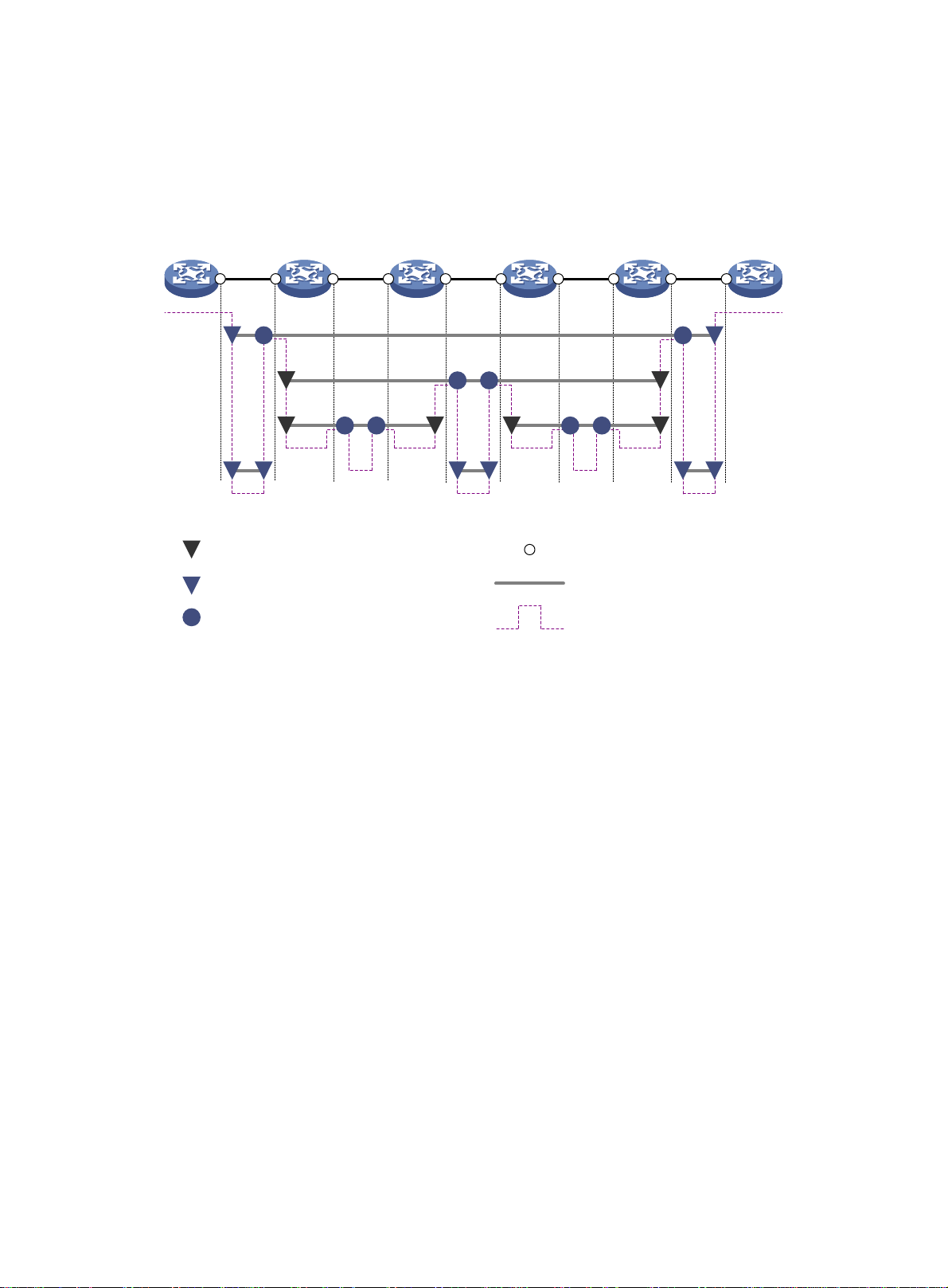
• A level 5 MIP.
• A level 3 inward-facing MEP.
• A level 2 inward-facing MEP.
• A level 0 outward-facing MEP.
Figure 3 CFD grading example
Device A Device B Device C Device D Device E Device F
Port 1
5 5
5 5
MEP list
3
2 2 2 2
0 0 0 0 0 0
3
Inward-facing MEP (number is MD level)
5
Outward-facing MEP (number is MD level)
5
MIP (number is MD level)
2 2 2 2
3 3
Interface
Maintenance association
Logical path of CFD PDUs
3
A MEP list is a collection of local MEPs allowed to be configured and the remote MEPs to be
monitored in the same MA. It lists all the MEPs configured on different devices in the same MA . The
MEPs all have unique MEP IDs. When a MEP receives from a remote device a continuity check
message (CCM) carrying a MEP ID not in the MEP list of the MA, it drops the message.
The local device must send CCM messages carrying the Remote Defect Indication (RDI) flag bits.
Otherwise, the peer device cannot sense certain failures. When a local MEP has not learned all
remote MEPs in the MEP list, the MEPs in the MA do not carry the RDI flag bits in CCMs.
CFD functions
CFD functions, which are implemented through the MPs, include:
• Continuity check (CC)
• Loopback (LB)
• Linktrace (LT)
• Alarm indication signal (AIS)
• Loss measurement (LM)
• Delay measurement (DM)
• Test (TST)
Continuity check
Connectivity faults are usually caused by device faults or configuration errors. Continuity check
examines the connectivity between MEPs. This function is implemented through periodic sending of
3
Page 10

CCMs by the MEPs. A CCM sent by one MEP is intended to be received by all the other MEPs in the
same MA. If a MEP fails to receive the CCMs within 3.5 times the sending interval, the link is
considered as faulty and a log is generated. When multiple MEPs send CCMs at the same ti me, the
multipoint-to-multipoint link check is achieved. CCM frames are multicast frames.
Loopback
Similar to ping at the IP layer, loopback verifies the connectivity between a source device and a
target device. To implement this function, the source MEP sends loopback messages (LBMs) to the
target MEP. Depending on whether the source MEP can receive a loopback reply message (LBR)
from the target MEP, the link state between the two can be verified.
LBM frames are multicast and unicast frames. The switch supports sending and receiving unicast
LBM frames and receiving multicast LBM frames. HPE devices do not support sending multicast
LBM frames. LBR frames are unicast frames.
Linktrace
Linktrace is similar to traceroute. It identifies the path between the source MEP and the target MP.
The source MEP sends the linktrace messages (LTMs) to the target MP. After receiving the
messages, the target MP and the MIPs that the LTM frames pass send back linktrace reply
messages (L TRs) to the source MEP. Based on the reply messages, the source MEP can identify the
path to the target MP. LTM frames are multicast frames and LTRs are unicast frames.
AIS
The AIS function suppresses the number of erro r alar ms reported by MEPs. If a local MEP do es not
receive any CCM frames from its peer MEP within 3.5 times the CCM transmission interval, it
immediately starts sending AIS frames. The AIS frames are sent periodically in the opposite direction
of CCM frames. When the peer MEP receives the AIS frames, it suppresses th e error alarms lo cally,
and continues to send the AIS frames. If the local MEP receives CCM frames within 3.5 times the
CCM transmission interval, it stops sending AIS frames and restores the error alarm function. AIS
frames are multicast frames.
LM
DM
The LM function measures the frame loss in a certain direction between a pair of MEPs. The source
MEP sends loss measurement messages (LMMs) to the target ME P. The target MEP responds with
loss measurement replies (LMRs). The source MEP calculates the numbe r of lost frames a cco rding
to the counter values of the two consecutive LMRs (the current LMR and the previous LMR). LMMs
and LMRs are unicast frames.
The DM function measures frame delays between two MEPs, including the following types:
• One-way frame delay measurement
The source MEP sends a one-way delay measurement (1DM) frame, which carries the
transmission time, to the target MEP. When the target MEP receives the 1DM frame, it does the
following:
{ Records the reception time.
{ Calculates and records the link transmission delay and jitter (delay variation) according to
the transmission time and reception time.
1DM frames are unicast frames.
• Two-way frame delay measurement
The source MEP sends a delay measurement message (DMM), which carries the transmi ssion
time, to the target MEP. When the target MEP receives the DMM, it responds with a delay
measurement reply (DMR). The DMR carries the reception time and transmission time of the
DMM and the transmission time of the DMR. When the source MEP receives the DMR, it does
the following:
{ Records the DMR reception time.
4
Page 11

{ Calculates the link transmission delay and jitter according to the DMR reception time and
DMM transmission time.
DMM frames and DMR frames are unicast frames.
TST
The TST function tests the bit errors between two MEPs. The source MEP sends a TST frame, whi ch
carries the test pattern, such as pseudo random bit sequence (PRBS) or all-zero, to the target MEP.
When the target MEP receives the TST frame, it determines the bit errors by calculating and
comparing the content of the TST frame. TST frames are unicast frames.
EAIS
Ethernet Alarm Indication S ignal (EAIS ) enables collaboratio n between the Et hernet port status and
the AIS function. When a port on the device (not necessarily an MP) goes down, it immediately starts
to send EAIS frames periodically to suppress the error alarms. When the port goes up again, it
immediately stops sending EAIS frames. When the MEP receives the EAIS frames, it suppresses
the error alarms locally, and continues to send the EAIS frames. If a MEP receives no EAIS frames
within 3.5 times the EAIS frame transmission interval, the fault is considered cleared. The port stops
sending EAIS frames and restores the error alarm function. EAIS frames are multicast frames.
Protocols and standards
• IEEE 802.1ag, Virtual Bridged Local Area Networks Amendment 5: Connectivity Fault
Management
• ITU-T Y.1731, OAM functions and mechanisms for Ethernet based networks
CFD configuration task list
For CFD to work correctly, design the network by performing the following tasks:
• Grade the MDs in the entire network, and define the boundary of each MD.
• Assign a name for each MD. Make sure that the devices in the same MD use the same MD
name.
• Define the MA in each MD according to the VLAN you want to monitor.
• Assign a name for each MA. Make sure that the devices in the same MA in the same MD use
the same MA name.
• Determine the MEP list of each MA in each MD. Make sure that devices in the same MA
maintain the same MEP list.
• At the edges of MD and MA, MEPs must be designed at the device port. MIPs can be designed
on devices or ports that are not at the edges.
To configure CFD, perform the following tasks:
Tasks at a glance
Configuring basic CFD settings:
• (Required.) Enabling CFD
• (Req
• (Req
• (Req
uired.) Configuring Ethernet service instances
uired.) Configuring MEPs
uired.) Configuring MIP auto-generation rules
Configuring CFD functions:
5
Page 12

Tasks at a glance
• (Required.) Configuring CC
• (Optional.) Configuring LB
• (Optional.) Configuring LT
• (Optional.) Configuring AIS
• (Optional.) Configuring LM
• (Optional.) Configuring one-way DM
• (Optional.) Configuring two-way DM
• (Optional.) Configuring TST
(Optional.) Configuring EAIS
Typically, a port blocked by the spanning tree feature cannot receive or send CFD messages except
in the following cases:
• The port is configured as an outward-facing MEP.
• The port is configured as a MIP or inward-facing MEP, which can still receive and send CFD
messages except CCM messages.
For more information about the spanning tree feature, see Layer 2—LAN Switching Configuration
Guide.
Configuring basic CFD settings
Enabling CFD
Step Command Remarks
1. Enter system view.
2. Enable CFD.
system-view
cfd enable
Configuring Ethernet service instances
Before configuring the MEPs and MIPs, you must first configure Ethernet service instances. An
Ethernet service instance is a set of service access points (SAPs), and belongs to an MA in an MD.
The MD and MA define the level attribute and VLAN attribute of the messages ha ndled by the MPs in
an Ethernet service instance. The MPs of the MA that carri es no VLAN attribute do not belong to any
VLAN.
To configure an Ethernet service instance with the MD name:
Step Command Remarks
1. Enter system view.
2. Create an MD.
system-view
cfd md
md-name [
index-value ]
level
index
level-value
N/A
By default, CFD is disabled.
N/A
By default, no MDs exist.
3. Create an Ethernet service
instance.
cfd service-instance
ma-id
integer
ma-name |
[
md-name [
icc-based
{
ma-num |
ma-index
ma-name |
string
vlan-based
index-value ] md
vlan
vlan-id ]
6
instance-id
[ vlan-id ] }
By default, no Ethernet service
instance exists.
Page 13

Configuring MEPs
CFD is implemented through various operations on MEPs. As a MEP is configured on an Ethernet
service instance, the MD level and VLAN attribute of the Ethernet service instance become the
attribute of the MEP.
Before creating MEPs, configure the MEP list. A MEP list is a collection of local MEPs that can be
configured in an MA and the remote MEPs to be monitored. You cannot create a MEP if the MEP ID
is not included in the MEP list of the Ethernet service instance.
You can specify an interface as the MEP for only one of the non-VLAN-specific MAs at the same
level. In addition, the MEP must be outward facing.
If a MEP in a non-VLAN-specific MA does not re ceive a CCM message within 3.5 CCM intervals fro m
a remote MEP, the local MEP sets its interface to link down state. This behavior of the local MEP
facilitates fast switchover for RRPP or Smart Link.
To configure a MEP:
Step Command Remarks
1. Enter system view.
system-view
N/A
2. Configure a MEP list.
3. Enter Layer 2 Ethernet
interface view or Layer 2
aggregate interface view.
4. Create a MEP.
cfd meplist
service-instance
interface
interface-number
cfd mep
service-instance
inbound
{
mep-list
interface-type
mep-id
outbound
|
instance-id
instance-id
}
Configuring MIP auto-generation rules
As functional entities in an Ethernet service instance, MIPs respond to various CFD frames, such as
LTM and LBM frames. You can configure MIP auto-generation rules for the system to automatically
create MIPs.
Any of the following events can cause MIPs to be created or deleted after you have configured the
cfd mip-rule command:
• Enabling or disabling CFD.
• Creating or deleting MEPs on a port.
• Changes occur to the VLAN attribute of a port.
• The rule specified in the cfd mip-rule command changes.
An MA carrying no VLAN attribute is typically used to detect direct link status. The system cannot
generate MIPs for such MAs.
By default, no MEP list is
configured.
N/A
By default, no MEPs are
configured.
For an MA carrying VLAN attribute, the system does not generate MIPs if the same or a higher level
MEP exists on the interface.
To configure the rules for generating MIPs:
Step Command Remarks
1. Enter system view.
2. Configure MIP
auto-generation rules.
system-view
cfd mip-rule { default | explicit }
service-instance
7
instance-id
N/A
By default, no rules for generating
MIPs are configured, and the
system does not automatically
Page 14

Step Command Remarks
Configuring CFD functions
Configuration prerequisites
Complete basic CFD settings.
Configuring CC
Configure CC before you use the MEP ID of the remote MEP to configure other CFD fun ctions. This
restriction does not apply when you use the MAC address of the remote MEP to configure other CF D
functions.
After the CC function is configured, MEPs in an MA can periodically send CCM frames to maintain
connectivity. When the lifetime of a CCM frame expires, the link to the sending MEP is considered
disconnected. When setting the CCM interval, use the settings described in Table 1.
create any MIP.
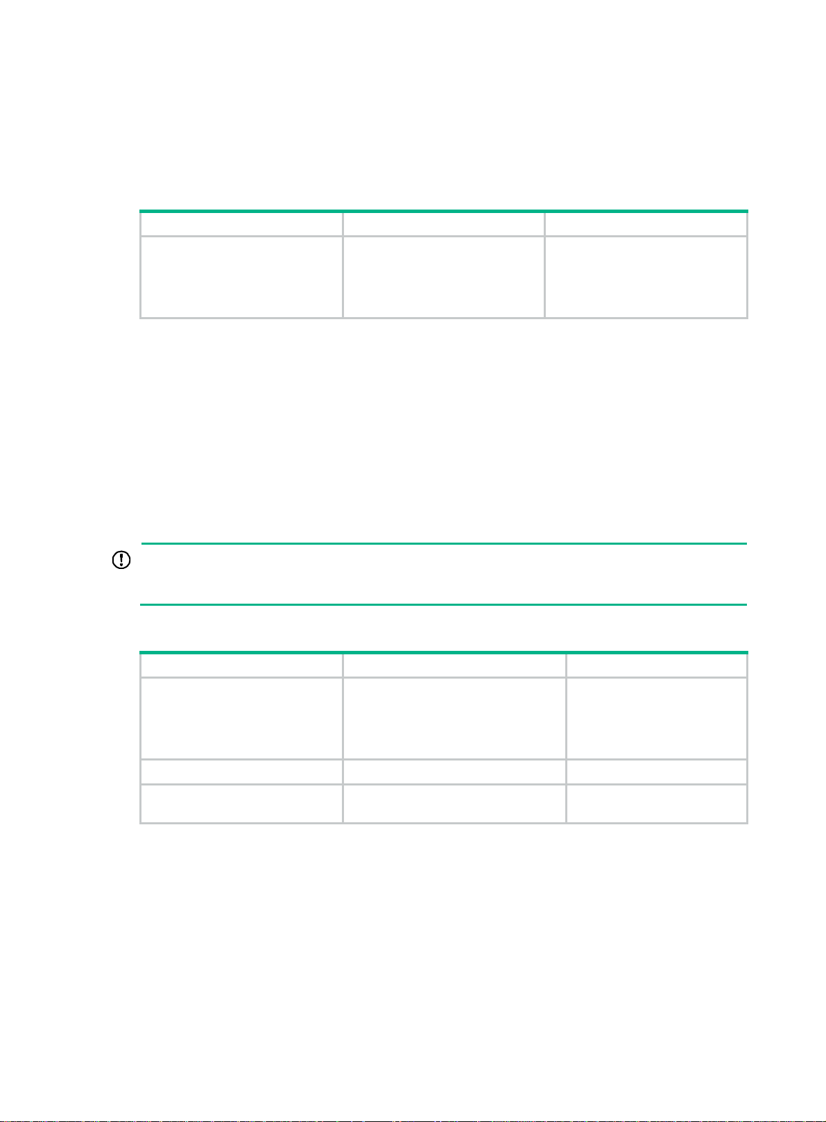
Table 1
CCM interval field encoding
CCM interval field Transmission interval Maximum CCM lifetime
3 100 milliseconds 350 milliseconds
4 1 second 3.5 seconds
5 10 seconds 35 seconds
6 60 seconds 210 seconds
7 600 seconds 2100 seconds
NOTE:
• The value range for the interval field value is 3 to 7.
• The CCM messages with an interval field value of 1 to 3 are short-interval CCM messages. The
CCM messages with an interval field value of 4 to 7 are long-interval CCM messages.
Follow these guidelines when you configure CC on a MEP:
• Configure the same CCM interval field value for all MEPs in the same MA.
• After the CCM interval field is modified, the MEP must wait for another CCM interval before
sending CCMs.
To configure CC on a MEP:
Step Command Remarks
1. Enter system view.
2. (Optional.) Set the CCM
interval field.
3. Enter Layer 2 Ethernet
interface view or Layer 2
aggregate interface view.
4. Enable CCM sending on a
MEP.
system-view
cfd cc interval
service-instance
interface
interface-number
cfd cc service-instance
instance-id
interval-value
instance-id
interface-type
mep
mep-id
8
enable
N/A
By default, the interval field value
is 4.
N/A
By default, CCM sending is
disabled on a MEP.
Page 15
Configuring LB
The LB function can verify the link state between the local MEP and the remote MEP or MIP.
To configure LB on a MEP:
Task Command Remarks
Enable LB.
Configuring LT
LT can trace the path between source and target MEPs, and can locate link faults by automatically
sending LT messages. The two functions are implemented in the following way:
• Tracing path—The source MEP first sends LTM messages to the target MEP. Based on the
L TR messages in response to the LTM messages, the path between the two MEPs is identified.
• LT messages automatic sending—If the source MEP fails to receive CCM frames from the
target MEP within 3.5 times the transmission interval, it considers the link faulty. The source
MEP then sends LTM frames, with the TTL field set to the maximum value 255, to the target
MEP. Based on the returned L TRs, the fault source is located.
cfd loopback service-instance
instance-id
target-mac
{
target-mep
number
[
mep
mac-address |
target-mep-id }
number ]
mep-id
Available in any view.
IMPORTANT:
Before you configure LT on a MEP in an MA carrying VLAN attribute, create the VLAN to which the
MA belongs.
To configure LT on MEPs:
Step Command Remarks
1. Identify the path between a
source MEP and a target
MEP.
2. Enter system view.
3. Enable LT messages
automatic sending.
Configuring AIS
The AIS function suppresses the number of error alarms reported by MEPs.
To make a MEP in the Ethernet service instance send AIS frames, set the AIS frame transmission
level to be higher than the MD level of the MEP.
cfd linktrace service-instance
instance-id
mac-address |
target-mep-id } [
hw-only
[
system-view
cfd linktrace auto-detection [ size
size-value ]
mep
target-mep
]
mep-id {
ttl
target-mac
ttl-value ]
Available in any view.
N/A
By default, LT messages
automatic sending is disabled.
Enable AIS and configure a correct AIS frame transmission level on the target MEP, so the target
MEP can do the following:
• Suppress the error alarms.
9
Page 16

• Send the AIS frame to the MD of a higher level.
If you enable AIS but do not configure a correct AIS frame transmission level, the target MEP can
suppress the error alarms, but cannot send the AIS frames.
To configure AIS:
Step Command Remarks
1. Enter system view.
2. Enable AIS.
system-view
cfd ais enable
N/A
By default, AIS is disabled.
3. Configure the AIS frame
transmission level.
4. Configure the AIS frame
transmission interval.
Configuring LM
The LM function measures frame loss between MEPs. Frame loss statistics include the number of
lost frames, the frame loss ratio, and the average number of lost frames for the source and target
MEPs.
To configure LM:
Task Command Remarks
cfd slm service-instance
target-mac
Configure LM.
mep-id {
target-mep
dot1p-value ] [
interval ]
Configuring one-way DM
cfd ais level
service-instance
cfd ais period
service-instance
target-mep-id } [
number
level-value
period-value
instance-id
mac-address |
number ] [
instance-id
instance-id
mep
dot1p
interval
By default, the AIS frame
transmission level is not
configured.
By default, the AIS frame
transmission interval is 1 second.
Available in any view.
The one-way DM function measures the one-way frame delay between two MEPs, and monitors and
manages the link transmission performance.
One-way DM requires that the time setting at the transmitting MEP and the receiving MEP be the
same. For the purpose of frame delay variation measurement, the requirement can be relaxed.
To view the test result, use the display cfd dm one-way history command on the target MEP.
To configure one-way DM:
Task Command Remarks
cfd dm one-way
Configure one-way DM.
service-instance
mep
mep-id {
mac-address |
target-mep-id } [
target-mac
target-mep
number
10
instance-id
Available in any view.
number ]
Page 17

Configuring two-way DM
The two-way DM function measures the two-way frame delay, average two-way frame delay, and
two-way frame delay variation between two MEPs. It also monitors and manages the link
transmission performance.
To configure two-way DM:
Task Command Remarks
Configure two-way DM.
Configuring TST
The TST function detects bit errors on a link, and monitors and manages the link transmission
performance.
To view the test result, use the display cfd tst command on the target MEP.
To configure TST:
cfd dm two-way
service-instance
mep
mep-id {
mac-address |
target-mep-id }
dot1p-value ] [
interval
[
target-mac
target-mep
dot1p
number
interval ]
instance-id
number ]
Available in any view.
Task Command Remarks
Configure TST.
Configuring EAIS
You can configure EAIS on a device that does not support or is not configured with CFD. However,
EAIS must collaborate with the CFD function in the network, so you must configure CFD in the
network.
To make a port send the EAIS frames, configure port status-AIS collaboration, and configure the
correct EAIS frame transmission level and interval. If you only enable port status-EAIS collaboration,
but do not configure the EAIS frame transmission level and interval, the port cannot send EAIS
frames.
If you do not specify the VLANs where the EAIS frames can be transmitted, the EAIS frames will be
transmitted in the default VLAN of the current port. Otherwise, the EAIS frames will be transmitted in
the intersection of the following VLANs:
• Specified VLANs where the EAIS frames can be transmitted.
• VLANs to which the port belongs.
cfd tst service-instance
instance-id
target-mac
{
target-mep
number
[
length-of-test
[
pattern-of-test { all-zero
[
with-crc
[
mep
mep-id
mac-address |
target-mep-id }
number ]
length ]
] ]
|
prbs
Available in any view.
}
The EAIS configuration on a member port of an aggregation group takes effect only after the
member port leaves the aggregation group.
11
Page 18

If the intersection of the configured VLANs where the EAIS frames can be transmitted and the
VLANs to which the port belongs is empty, no EAIS frame is sent. If the intersection contains more
than 70 VLANs and the EAIS frame transmission interval is 1 second, the CPU u sage will be too high.
As a best practice, set the EAIS frame transmission interval to 60 seconds in this case.
To configure EAIS:
Step Command Remarks
1. Enter system view.
2. Enable port status-AIS
collaboration.
3. Enter Layer 2 Ethernet
interface view or Layer 2
aggregate interface view.
system-view
cfd ais-track link-status global
interface
interface-number
interface-type
N/A
By default, port status-AIS
collaboration is disabled.
N/A
4. Configure the EAIS frame
transmission level.
5. Configure the EAIS frame
transmission interval.
6. Specify the VLANs where
the EAIS frames can be
transmitted.
cfd ais-track link-status level
level-value
cfd ais-track link-status period
period-value
cfd ais-track link-status vlan
vlan-list
Displaying and maintaining CFD
Execute display commands in any view and reset commands in user view.
Task Command
Display the AIS configuration and information on the
specified MEP.
Display the AIS configuration and information
associated with the status of the specified port.
Display the one-way DM result on the specified
MEP.
display cfd ais
mep
[
mep-id ] ]
display cfd ais-track link-status
interface-type interface-number ]
display cfd dm one-way history
service-instance
[
By default, the EAIS frame
transmission level is not
configured.
By default, the EAIS frame
transmission interval is not
configured.
By default, the EAIS frames can
only be transmitted within the
default VLAN of the port.
service-instance
[
instance-id [
instance-id
interface
[
mep
mep-id ] ]
Display LTR information received by a MEP.
Display the content of the LTR messages received
as responses to the automatically sent LTMs.
Display MD configuration information.
Display the attribute and running information of the
MEPs.
Display MEP list in an Ethernet service instance.
Display MP information.
Display information about a remote MEP.
Display Ethernet service instance configuration
information.
12
display cfd linktrace-reply
instance-id [
display cfd linktrace-reply auto-detection [ size
size-value ]
display cfd md
display cfd mep
instance-id
display cfd meplist [ service-instance
display cfd mp [ interface
interface-number ]
display cfd remote-mep service-instance
instance-id
display cfd service-instance
mep
mep
mep-id ] ]
mep-id
mep-id
service-instance
[
service-instance
interface-type
[ instance-id ]
instance-id ]
Page 19
Task Command
Display CFD status.
display cfd status
Display the TST result on the specified MEP.
Clear the one-way DM result on the specified MEP.
Clear the TST result on the specified MEP.
CFD configuration example
Network requirements
As shown in Figure 4:
• The network comprises five devices and is divided into two MDs: MD_A (level 5) and MD_B
(level 3). All ports belong to VLAN 100, and the MAs in the two MDs all serve VLAN 100.
Assume that the MAC addresses of Device A through Device E are 0010-FC01-6511,
0010-FC02-6512, 0010-FC03-6513, 0010-FC04-6514, and 0010-FC05-6515, respectively.
• MD_A has three edge ports: GigabitEthernet 1/0/1 on Device A, GigabitEthernet 1/0/3 on
Device D, and GigabitEthernet 1/0/4 on Device E. They are all inward-facing MEPs. MD_B ha s
two edge ports: GigabitEthernet 1/0/3 on Device B and GigabitEthernet 1/0/1 on Device D.
They are both outward-facing MEPs.
• In MD_A, Device B is designed to have MIPs when its port is configured with low level MEPs.
Port GigabitEthernet 1/0/3 is configured with MEPs of MD_B, and the MIPs of MD_A can be
configured on this port. You must configure the MIP generation rule of MD_A as explicit.
• The MIPs of MD_B are designed on Device C, and are configured on all ports. You must
configure the MIP generation rule as default.
• Configure CC to monitor the connectivity among all the MEPs in MD_A and MD_B. Configure
LB to locate link faults, and use the AIS and EAIS functions to suppress the error alarms that
are reported.
• After the status information of the entire network is obtained, use L T, LM, one-way DM, two-way
DM, and TST to detect link faults.
display cfd tst
mep-id ] ]
reset cfd dm one-way history
instance-id [
reset cfd tst
mep-id ] ]
service-instance
[
mep
mep-id ] ]
service-instance
[
instance-id [
service-instance
[
instance-id [
mep
mep
Figure 4 Network diagram
13
Page 20

Configuration procedure
1. Configure a VLAN and assign ports to it:
On each device shown in Figure 4, cre
through GigabitEthernet 1/0/4 to VLAN 100.
2. Enable CFD:
# Enable CFD on Device A.
<DeviceA> system-view
[DeviceA] cfd enable
# Configure Device B through Device E in the same way Device A is configured. (Details not
shown.)
3. Configure Ethernet service instances:
# Create MD_A (level 5) on Device A, and create Ethernet service instance 1 (in whi ch the MA
is identified by a VLAN and serves VLAN 100).
[DeviceA] cfd md MD_A level 5
[DeviceA] cfd service-instance 1 ma-id vlan-based md MD_A vlan 100
# Configure Device E in the same way Device A is configured. (Details not shown.)
# Create MD_A (level 5) on Device B, and create Ethernet service instance 1 (in whi ch the MA
is identified by a VLAN and serves VLAN 100).
[DeviceB] cfd md MD_A level 5
[DeviceB] cfd service-instance 1 ma-id vlan-based md MD_A vlan 100
# Create MD_B (level 3), and create Ethernet service instance 2 (in which the MA is identified
by a VLAN and serves VLAN 100).
[DeviceB] cfd md MD_B level 3
[DeviceB] cfd service-instance 2 ma-id vlan-based md MD_B vlan 100
# Configure Device D in the same way Device B is configured. (Details not shown.)
# Create MD_B (level 3) on Device C, and create Ethernet service instance 2 (in which the MA
is identified by a VLAN and serves VLAN 100).
[DeviceC] cfd md MD_B level 3
[DeviceC] cfd service-instance 2 ma-id vlan-based md MD_B vlan 100
4. Configure MEPs:
# On Device A, configure a MEP list in Ethernet service instance 1, and create inward-facing
MEP 1001 in Ethernet service instance 1 on GigabitEthernet 1/0/1.
[DeviceA] cfd meplist 1001 4002 5001 service-instance 1
[DeviceA] interface gigabitethernet 1/0/1
[DeviceA-GigabitEthernet1/0/1] cfd mep 1001 service-instance 1 inbound
[DeviceA-GigabitEthernet1/0/1] quit
# On Device B, configure a MEP list in Ethernet service instances 1 and 2.
[DeviceB] cfd meplist 1001 4002 5001 service-instance 1
[DeviceB] cfd meplist 2001 4001 service-instance 2
# Create outward-facing MEP 2001 in Ethernet service instance 2 on GigabitEthernet 1/0/3.
[DeviceB] interface gigabitethernet 1/0/3
[DeviceB-GigabitEthernet1/0/3] cfd mep 2001 service-instance 2 outbound
[DeviceB-GigabitEthernet1/0/3] quit
# On Device D, configure a MEP list in Ethernet service instances 1 and 2.
[DeviceD] cfd meplist 1001 4002 5001 service-instance 1
[DeviceD] cfd meplist 2001 4001 service-instance 2
# Create outward-facing MEP 4001 in Ethernet service instance 2 on GigabitEthernet 1/0/1.
[DeviceD] interface gigabitethernet 1/0/1
ate VLAN 100 and assign ports GigabitEthernet 1/0/1
14
Page 21

[DeviceD-GigabitEthernet1/0/1] cfd mep 4001 service-instance 2 outbound
[DeviceD-GigabitEthernet1/0/1] quit
# Create inward-facing MEP 4002 in Ethernet service instance 1 on GigabitEthernet 1/0/3.
[DeviceD] interface gigabitethernet 1/0/3
[DeviceD-GigabitEthernet1/0/3] cfd mep 4002 service-instance 1 inbound
[DeviceD-GigabitEthernet1/0/3] quit
# On Device E, configure a MEP list in Ethernet service instance 1.
[DeviceE] cfd meplist 1001 4002 5001 service-instance 1
# Create inward-facing MEP 5001 in Ethernet service instance 1 on GigabitEthernet 1/0/4.
[DeviceE] interface gigabitethernet 1/0/4
[DeviceE-GigabitEthernet1/0/4] cfd mep 5001 service-instance 1 inbound
[DeviceE-GigabitEthernet1/0/4] quit
5. Configure MIPs:
# Configure the MIP generation rule in Ethernet service instance 1 on Device B as explicit.
[DeviceB] cfd mip-rule explicit service-instance 1
# Configure the MIP generation rule in Ethernet service instance 2 on Device C as default.
[DeviceC] cfd mip-rule default service-instance 2
6. Configure CC:
# On Device A, enable the sending of CCM frames for MEP 1001 in Ethernet service instance 1
on GigabitEthernet 1/0/1.
[DeviceA] interface gigabitethernet 1/0/1
[DeviceA-GigabitEthernet1/0/1] cfd cc service-instance 1 mep 1001 enable
[DeviceA-GigabitEthernet1/0/1] quit
# On Device B, enable the sending of CCM frames for MEP 2001 in Ethernet service instance 2
on GigabitEthernet 1/0/3.
[DeviceB] interface gigabitethernet 1/0/3
[DeviceB-GigabitEthernet1/0/3] cfd cc service-instance 2 mep 2001 enable
[DeviceB-GigabitEthernet1/0/3] quit
# On Device D, enable the sending of CCM frames for MEP 4001 in Ethernet se rvice instance 2
on GigabitEthernet 1/0/1.
[DeviceD] interface gigabitethernet 1/0/1
[DeviceD-GigabitEthernet1/0/1] cfd cc service-instance 2 mep 4001 enable
[DeviceD-GigabitEthernet1/0/1] quit
# Enable the sending of CCM frames for MEP 4002 in Ethernet service instance 1 on
GigabitEthernet 1/0/3.
[DeviceD] interface gigabitethernet 1/0/3
[DeviceD-GigabitEthernet1/0/3] cfd cc service-instance 1 mep 4002 enable
[DeviceD-GigabitEthernet1/0/3] quit
# On Device E, enable the sending of CCM frames for MEP 5001 in Ethernet service instance 1
on GigabitEthernet 1/0/4.
[DeviceE] interface gigabitethernet 1/0/4
[DeviceE-GigabitEthernet1/0/4] cfd cc service-instance 1 mep 5001 enable
[DeviceE-GigabitEthernet1/0/4] quit
7. Configure AIS:
# Enable AIS on Device B. Configure the AIS frame transmission level as 5 and AIS frame
transmission interval as 1 second in Ethernet service instance 2.
[DeviceB] cfd ais enable
[DeviceB] cfd ais level 5 service-instance 2
15
Page 22

[DeviceB] cfd ais period 1 service-instance 2
8. Configure EAIS:
# Enable port status-AIS collaboration on Device B.
[DeviceB] cfd ais-track link-status global
# On GigabitEthernet 1/0/3 of Device B, configure the EAIS frame transmission level as 5 and
the EAIS frame transmission interval as 60 seconds. Specify the VLANs where the EAIS frames
can be transmitted as VLAN 100.
[DeviceB] interface gigabitethernet 1/0/3
[DeviceB-GigabitEthernet1/0/3] cfd ais-track link-status level 5
[DeviceB-GigabitEthernet1/0/3] cfd ais-track link-status period 60
[DeviceB-GigabitEthernet1/0/3] cfd ais-track link-status vlan 100
Verifying the configuration
1. Verify the LB function when the CC function detects a link fault:
# Enable LB on Device A to check the status of the link between MEP 1001 and MEP 5001 in
Ethernet service instance 1.
[DeviceA] cfd loopback service-instance 1 mep 1001 target-mep 5001
Loopback to MEP 5001 with the sequence number start from 1001-43404:
Reply from 0010-fc05-6515: sequence number=1001-43404 time=5ms
Reply from 0010-fc05-6515: sequence number=1001-43405 time=5ms
Reply from 0010-fc05-6515: sequence number=1001-43406 time=5ms
Reply from 0010-fc05-6515: sequence number=1001-43407 time=5ms
Reply from 0010-fc05-6515: sequence number=1001-43408 time=5ms
Sent: 5 Received: 5 Lost: 0
2. Verify the LT function after the CC function obtains the status information of the entire network:
# Identify the path between MEP 1001 and MEP 5001 in Ethernet service instance 1 on Device
A.
[DeviceA] cfd linktrace service-instance 1 mep 1001 target-mep 5001
Linktrace to MEP 5001 with the sequence number 1001-43462:
MAC address TTL Last MAC Relay action
0010-fc05-6515 63 0010-fc02-6512 Hit
3. Verify the LM function after the CC function obtains the status information of the entire network:
# Test the frame loss from MEP 1001 to MEP 4002 in Ethernet service instance 1 on Device A.
[DeviceA] cfd slm service-instance 1 mep 1001 target-mep 4002
Reply from 0010-fc04-6514
Far-end frame loss: 10 Near-end frame loss: 20
Reply from 0010-fc04-6514
Far-end frame loss: 40 Near-end frame loss: 40
Reply from 0010-fc04-6514
Far-end frame loss: 0 Near-end frame loss: 10
Reply from 0010-fc04-6514
Far-end frame loss: 30 Near-end frame loss: 30
Average
Far-end frame loss: 20 Near-end frame loss: 25
Far-end frame loss rate: 25.00% Near-end frame loss rate: 32.00%
Send LMMs: 5 Received: 5 Lost: 0
4. Verify the one-way DM function after the CC function obtains the status information of the entire
network:
16
Page 23

# Test the one-way frame delay from MEP 1001 to MEP 4002 in Ethernet service instance 1 on
Device A.
[DeviceA] cfd dm one-way service-instance 1 mep 1001 target-mep 4002
5 1DMs have been sent. Please check the result on the remote device.
# Display the one-way DM result on MEP 4002 in Ethernet service instance 1 on Device D.
[DeviceD] display cfd dm one-way history service-instance 1 mep 4002
Service instance: 1
MEP ID: 4002
Sent 1DM total number: 0
Received 1DM total number: 5
Frame delay: 10ms 9ms 11ms 5ms 5ms
Delay average: 8ms
Delay variation: 5ms 4ms 6ms 0ms 0ms
Variation average: 3ms
5. Verify the two-way DM function after the CC function obtains the status information of the entire
network:
# Test the two-way frame delay from MEP 1001 to MEP 4002 in Ethernet service instance 1 on
Device A.
[DeviceA] cfd dm two-way service-instance 1 mep 1001 target-mep 4002
Frame delay:
Reply from 0010-fc04-6514: 2406us
Reply from 0010-fc04-6514: 2215us
Reply from 0010-fc04-6514: 2112us
Reply from 0010-fc04-6514: 1812us
Reply from 0010-fc04-6514: 2249us
Average: 2158us
Sent DMMs: 5 Received: 5 Lost: 0
Frame delay variation: 191us 103us 300us 437us
Average: 257us
6. Verify the TST function after the CC function obtains the status information of the entire
network:
# Test the bit errors on the link from MEP 1001 to MEP 4002 in Ethernet service instance 1 on
Device A.
[DeviceA] cfd tst service-instance 1 mep 1001 target-mep 4002
5 TSTs have been sent. Please check the result on the remote device.
# Display the TST result on MEP 4002 in Ethernet service instance 1 on Device D.
[DeviceD] display cfd tst service-instance 1 mep 4002
Service instance: 1
MEP ID: 4002
Sent TST total number: 0
Received TST total number: 5
Received from 0010-fc01-6511, Bit True, sequence number 0
Received from 0010-fc01-6511, Bit True, sequence number 1
Received from 0010-fc01-6511, Bit True, sequence number 2
Received from 0010-fc01-6511, Bit True, sequence number 3
Received from 0010-fc01-6511, Bit True, sequence number 4
17
Page 24
Configuring DLDP
Overview
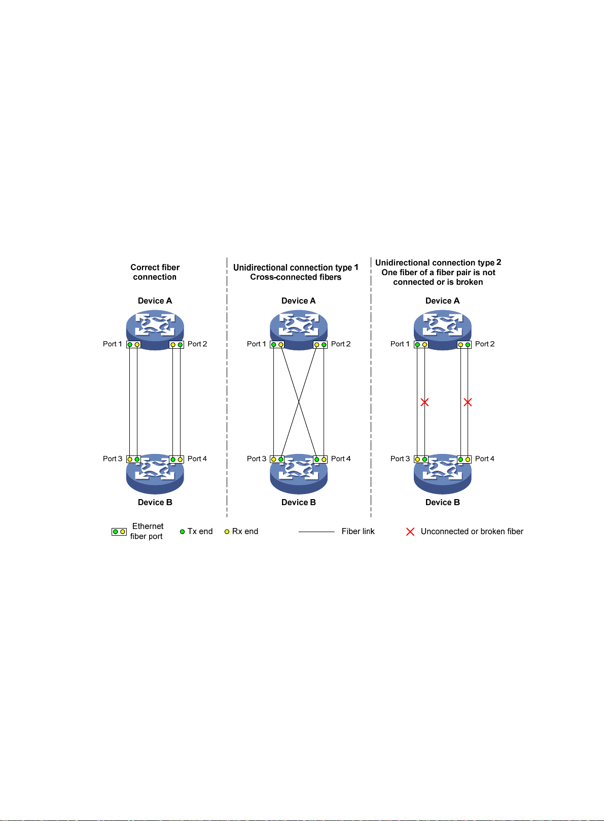
A link becomes unidi rectio nal when only one end of the link can receive packets from the other end.
Unidirectional fiber links occur in the following cases:
• Fibers are cross-connected.
• A fiber is not con ne cted at one en d or one fiber of a fiber pair is broken.
Figure 5 sh
Figure 5 Correct and incorrect fiber connections
ows a correct fiber connection and two types of unidirectional fiber connections.
Physical layer detection mechanisms, such as auto-negotiation, can detect physical signals and
faults. However, they cannot detect communication failures for unidirectional links where the
physical layer is in connected state.
As a data link layer protocol, the Device Link Detection Protocol (DLDP) detects the following:
• Whether the fiber link or twisted-pair link is correctly connected at the link layer.
• Whether the two ends of the link can exchange packets correctly.
When DLDP detects unidirectional links, it can automatically shut down the faulty port to avoid
network problems. Alternatively, a user can manually shut down the faulty port. DLDP cooperates
with physical layer protocols to monitor link status and avoid physical and logical unidirectional links.
18
Page 25

Basic concepts
DLDP neighbor states
If port A can receive link-layer packets from port B on the same link, port B is a DLDP neighbor of port
A. Two ports that can exchange packets are neighbors.
Table 2 DLDP neighbor states
DLDP timer Description
Confirmed The link to a DLDP neighbor is bidirectional.
Unconfirmed The state of the link to a newly discovered neighbor is not determined.
DLDP port states
A DLDP-enab led port is call ed a DLDP port. A DLDP port can have multiple neighbors, and its state
varies by the DLDP neighbor state.
Table 3 DLDP port states
State Description
Initial DLDP is enabled on the port, but is disabled globally.
Inactive DLDP is enabled on the port and globally, and the link is physically down.
Bidirectional
Unidirectional
DLDP timers
Table 4 DLDP timers
DLDP timer Description
Advertisement timer
Probe timer Probe packet sending interval. This timer is set to 1 second.
Echo timer
Entry timer
Enhanced timer
DLDP is enabled on the port and globally, and at least one neighbor in
Confirmed state exists.
DLDP is enabled on the port and globally, and no neighbor in Confirmed s tate
exists. In this state, a port does not send or receive packets other than DLDP
packets any more.
Advertisement packet sending interval (the default is 5 seconds and is
configurable).
The Echo timer is triggered when a probe is launched for a new neighbor. This
timer is set to 10 seconds.
When a new neighbor joins, a neighbor entry is created and the corresponding
entry timer is triggered if the neighbor is in Confirmed state. When an
Advertisement is received, the device updates the corresponding neighbor entry
and the Entry timer.
The setting of an Entry timer is three times that of the Advertisement timer.
The Enhanced timer is triggered, together with the Echo timer, when the Entry
timer expires. The Enhanced timer is set to 1 second.
DelayDown timer
RecoverProbe timer
If a port is physically down, the device triggers the DelayDown timer, rather than
removing the corresponding neighbor entry. The default DelayDown timer is 1
second and is configurable.
When the DelayDown timer expires, the device removes the corresponding
DLDP neighbor information if the port is down, and does not perform any
operation if the port is up.
This timer is set to 2 seconds. A port in unidirectional state regularly sends
19
Page 26
DLDP timer Description
DLDP authentication mode
You can use DLDP authentication to prevent network attacks and illegal detecting.
Table 5 DLDP authentication mode
RecoverProbe packets to detect whether a unidirectional link has been restored
to bidirectional.
Authentication
mode
Non-authentication
Plaintext
authentication
MD5
authentication
Processing at the DLDP packet sending side
The sending side sets the Authentication field of DLDP
packets to 0.
The sending side sets the Authentication field to the
password configured in plain text.
The sending side encrypts the user configured password
by using MD5 algorithm, and assigns the digest to the
Authentication field.
How DLDP works
Detecting one neighbor
When two devices are connected through an optical fiber or a net work cable, enable DLDP to detect
unidirectional links to the neighbor. The following illustrates the unidirectional link detection process
in two cases:
• Unidirectional links occur before you enable DLDP.
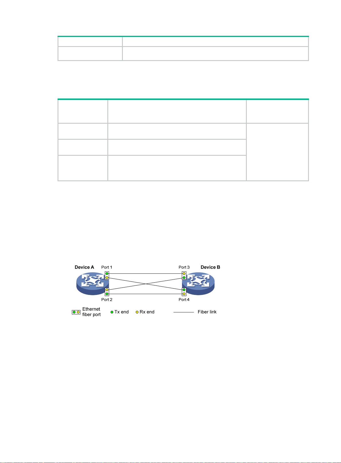
Figure 6 Cross-connected fibers
Processing at the
DLDP packet
receiving side
The receiving side
examines the
authentication
information of received
DLDP packets and
drops packets where the
authentication
information conflicts with
the local configuration.
As shown in Figure 6, before you enable DLDP, the optical fibers between Device A and Device
B are cross-connected. After you enable DLDP, the four ports are all up and in unidirectional
state, and they send RecoverProbe packets. Take Port 1 as an example to illustrate the
unidirectional link detection process.
a. Port 1 receives the RecoverProbe packet from Port 4, and returns a RecoverEcho packet.
b. Port 4 cannot receive any RecoverEcho packet from Port 1, so Port 4 cannot become the
neighbor of Port 1.
c. Port 3 can receive the RecoverEcho packet from Port 1, but Port 3 is not the intended
destination, so Port 3 cannot become the neighbor of Port 1.
The same process occurs on the other three ports. The four ports are all in uni directional state.
• Unidirectional links occur after you enable DLDP.
20
Page 27
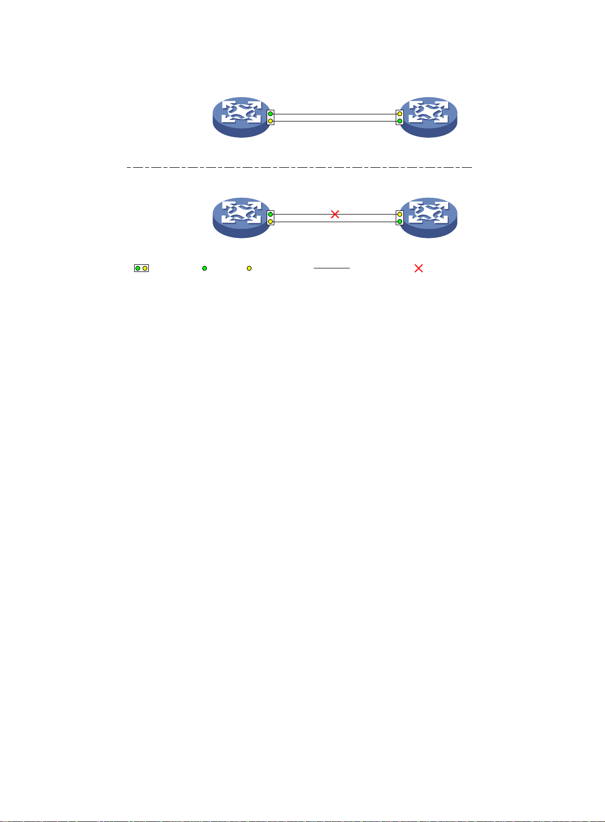
Figure 7 Broken fiber
Correct fiber
connection
One fiber is
broken
Device A Device B
Port 1 Port 2
Device A Device B
Port 1 Port 2
Ethernet
fiber port
Tx end Rx end
Fiber link
Broken fiber
As shown in Figure 7, Device A and Device B are connected through an optical fiber. After you
enable DLDP, Port 1 and Port 2 establish the bidirectional neighborship in the following way:
a. Port 1 that is physically up enters the unidirectional state and sends a RecoverProbe
packet.
b. After receiving the RecoverProb e packet, Port 2 returns a RecoverEcho packet.
c. After Port 1 receives the RecoverEcho packet, it examines the neighbor information in the
packet. If the neighbor information matches the local information, Port 1 establishes the
neighborship with Port 2 and transits to bidirectional state. Port 1 then starts the Entry timer
and periodically sends Advertisement packets.
d. After Port 2 receives the Advertisem ent packet, it establishes the Unconfirmed neighborship
with Port 1. Port 2 then starts the Echo timer and Probe timer, and periodically sends Probe
packets.
e. After receiving the Probe packet, Port 1 returns an Echo packet.
f. After Port 2 receives the Echo packet, it examines the neighbor information in the packet. If
the neighbor information matches the local information, the neighbor state of Port 1
becomes Confirmed. Port 2 then transits to bidirectional state, starts the Entry timer, and
periodically sends Advertisement packets.
The bidirectional neighborship between Port 1 and Port 2 is now established.
After that, when Port 2's Rx end fails to receive signals, Port 2 is physically down a nd enters the
Inactive state. Because Port 2's Tx end can still send signals to Port 1, Port 1 stays up. After the
Entry timer for Port 2 expires, Port 1 starts the Enhanced timer and Echo timer, and sends a
probe packet to Port 2. Because Port 1's Tx line is broken, Port 1 cannot receive the Echo
packet from Port 2 after the Echo timer expires. Port 1 then enters the unidirectional state, an d
sends a Disable packet to Port 2. At the same time, Port 1 deletes the nei ghborship with Port 2,
and starts the RecoverProbe timer. Port 2 stays in Inactive state during this process.
When an interface is physically down, but the Tx end of the interface is still operating, DLDP
sends a LinkDown packet to inform the peer to delete the relevant neighbor entry.
Detecting multiple neighbors
When multiple devices are connected through a hub, enable DLDP on all interfaces conne cted to the
hub to detect unidirectional links among the neighbors. When no Confirmed neighbor exists, an
interface enters the unidirectional state.
21
Page 28
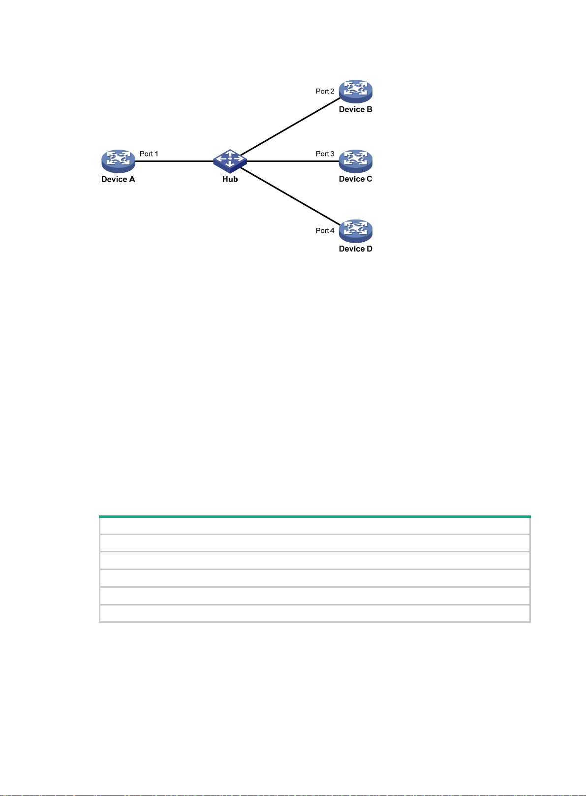
Figure 8 Network diagram
As shown in Figure 8, Device A through Device D are connected through a hub, and enabled with
DLDP. When Ports 1, 2, and 3 detect that the link to Port 4 fails, they delete the neighborship with
Port 4, but stay in bidirectional state.
Configuration restrictions and guidelines
When you configure DLDP, follow these configuration restrictions and guidelines:
• For DLDP to operate correctly , enable DLDP on both sides and make sure the following settings
are consistent:
{ Interval to send Advertisement packets.
{ DLDP authentication mode.
{ Password.
• For DLDP to operate correctly , configure the full duplex mode for the ports at the two ends of the
link, and configure the same speed for the two ports.
DLDP configuration task list
Tasks at a glance
(Required.) Enabling DLDP
(Optional.) Setting the interval to send advertisement packets
(Optional.) Setting the DelayDown timer
(Optional.) Setting the port shutdown mode
(Optional.) Configuring DLDP authentication
Enabling DLDP
To correctly configure DLDP on the device, you must enable DLDP globally and on each port.
To enable DLDP:
22
Page 29

Step Command Remarks
1. Enter system view.
system-view
N/A
2. Enable DLDP globally.
3. Enter Ethernet interface
view.
4. Enable DLDP.
dldp global enable
interface
interface-number
dldp enable
interface-type
By default, DLDP is globally
disabled.
N/A
By default, DLDP is disabled on
an interface.
Setting the interval to send advertisement packets
To make sure DLDP can detect unidirectional links before network performance deteriorate s, set the
advertisement interval appropriate for your network environment. As a best practice, use the default
interval.
To set the Advertisement packet sending interval:
Step Command Remarks
1. Enter system view.
2. Set the interval to send
Advertisement packets.
system-view
dldp interval
interval
N/A
By default, the interval is 5
seconds.
Setting the DelayDown timer
When the Tx line fails, some ports might go down and then come up again, causing optical signal
jitters on the Rx line. To prevent the device from removing neighbor entries in such cases, set the
DelayDown timer for the device. The device starts the DelayDown timer when a port goes down due
to a Tx line failure. If the port remains down when the timer expires, the device removes the DLDP
neighbor information. If the port comes up, the device takes no action.
To set the DelayDown timer:
Step Command Remarks
1. Enter system view.
2. Set the DelayDown timer.
system-view
dldp delaydown-timer
time
Setting the port shutdown mode
On detecting a unidirectional link, DLDP shuts down the ports in on e of the following modes:
• Auto mode—When DLDP detects a unidirectional link, it shuts down the unidirectional port.
When the link becomes bidirectional, DLDP brings up the port that was shut down.
• Hybrid mode—When DLDP detects a unidirectional link, it shuts down the unidirectional port
and stops link detection. T o verify the link status, use the undo shut down command to bring up
the port. If the link becomes bidirectional, the port becomes bidirectional.
N/A
The default is 1 second.
The DelayDown timer setting
applies to all DLDP-enabled ports.
23
Page 30

• Manual mode—When DLDP detects a unidirectional link, it does not shut down the port. You
must manually shut it down. When the link becomes bidirectional, you must manually bring up
the port. Use this mode to prevent normal links from being shut down because of false
unidirectional link reports in the following ca ses:
{ The network performance is low.
{ The device is busy.
{ The CPU usage is high.
To set port shutdown mode:
Step Command Remarks
1. Enter system view.
system-view
N/A
2. Set port shutdown mode.
dldp unidirectional-shutdown
auto
{
hybrid
|
manual
|
}
Configuring DLDP authentication
You can guard your network against attacks and malicious probes by configuring an appropriate
DLDP authentication mode, which can be plain text authentication or MD5 authentication. If your
network is safe, you can choose not to authenticate.
To configure DLDP authentication:
Step Command Remarks
1. Enter system view.
2. Configure a DLDP
authentication mode.
3. Configure the password for
DLDP authentication.
system-view
dldp authentication-mode
md5
none
simple
|
simple
|
}
} string
{
|
dldp authentication-password
cipher
{
The default mode is
N/A
The default authentication mode
none
is
By default, no password is
configured for DLDP
authentication.
If you do not configure the
authentication password after you
configure the authentication
mode, the authentication mode is
none
authentication mode you
configure.
.
no matter which
auto
.
Displaying and maintaining DLDP
Execute display commands in any view and the reset command in user view.
Task Command
Display the DLDP configuration globally and of a
port.
Display the statistics on DLDP packets passing
through a port.
Clear the statistics on DLDP packets passing
through a port.
24
display dldp
interface-number ]
display dldp statistics
interface-number ]
reset dldp statistics [ interface
interface-number ]
[
interface
interface-type
interface
[
interface-type
interface-type
Page 31

DLDP configuration examples
Configuring the auto port shutdown mode
Network requirements
As shown in Figure 9, Device A and Device B are connected through two fiber pairs.
Configure DLDP to automatically shut down the faulty port upon detecting a unidirectional link, and
automatically bring up the port after you clear the fault.
Figure 9 Network diagram
Configuration procedure
1. Configure Device A:
# Enable DLDP globally.
<DeviceA> system-view
[DeviceA] dldp global enable
# Configure GigabitEthernet 1/0/1 to operate in full duplex mode and at 1000 Mbps, and enable
DLDP on the port.
[DeviceA] interface gigabitethernet 1/0/1
[DeviceA-GigabitEthernet1/0/1] duplex full
[DeviceA-GigabitEthernet1/0/1] speed 1000
[DeviceA-GigabitEthernet1/0/1] dldp enable
[DeviceA-GigabitEthernet1/0/1] quit
# Configure GigabitEthernet 1/0/2 to operate in full duplex mode and at 1000 Mbps, and enable
DLDP on the port.
[DeviceA] interface gigabitethernet 1/0/2
[DeviceA-GigabitEthernet1/0/2] duplex full
[DeviceA-GigabitEthernet1/0/2] speed 1000
[DeviceA-GigabitEthernet1/0/2] dldp enable
[DeviceA-GigabitEthernet1/0/2] quit
# Set the port shutdown mode to auto.
[DeviceA] dldp unidirectional-shutdown auto
2. Configure Device B:
# Enable DLDP globally.
<DeviceB> system-view
[DeviceB] dldp global enable
# Configure GigabitEthernet 1/0/1 to operate in full duplex mode and at 1000 Mbps, and enable
DLDP on it.
[DeviceB] interface gigabitethernet 1/0/1
[DeviceB-GigabitEthernet1/0/1] duplex full
25
Page 32

[DeviceB-GigabitEthernet1/0/1] speed 1000
[DeviceB-GigabitEthernet1/0/1] dldp enable
[DeviceB-GigabitEthernet1/0/1] quit
# Configure GigabitEthernet 1/0/2 to operate in full duplex mode and at 1000 Mbps, and enable
DLDP on it.
[DeviceB] interface gigabitethernet 1/0/2
[DeviceB-GigabitEthernet1/0/2] duplex full
[DeviceB-GigabitEthernet1/0/2] speed 1000
[DeviceB-GigabitEthernet1/0/2] dldp enable
[DeviceB-GigabitEthernet1/0/2] quit
# Set the port shutdown mode to auto.
[DeviceB] dldp unidirectional-shutdown auto
Verifying the configuration
# Display the DLDP configuration globally and on all the DLDP-enabled ports of Device A.
[DeviceA] display dldp
DLDP global status: Enabled
DLDP advertisement interval: 5s
DLDP authentication-mode: None
DLDP unidirectional-shutdown mode: Auto
DLDP delaydown-timer value: 1s
Number of enabled ports: 2
Interface GigabitEthernet1/0/1
DLDP port state: Bidirectional
Number of the port’s neighbors: 1
Neighbor MAC address: 0023-8956-3600
Neighbor port index: 1
Neighbor state: Confirmed
Neighbor aged time: 11s
Interface GigabitEthernet1/0/2
DLDP port state: Bidirectional
Number of the port’s neighbors: 1
Neighbor MAC address: 0023-8956-3600
Neighbor port index: 2
Neighbor state: Confirmed
Neighbor aged time: 12s
The output shows that both GigabitEthernet 1/0/1 and GigabitEthernet 1/0/2 are bidirectional.
# Enable the monitoring of logs on the current terminal on Device A. Set the lowest level of the logs
that can be output to the current terminal to 6.
[DeviceA] quit
<DeviceA> terminal monitor
<DeviceA> terminal logging level 6
The following log information is displayed on Device A:
<DeviceA>%Jul 11 17:40:31:089 2012 DeviceA IFNET/3/PHY_UPDOWN: GigabitEthernet1/0/1 link
status is DOWN.
%Jul 11 17:40:31:091 2012 DeviceA IFNET/5/LINK_UPDOWN: Line protocol on the interface
GigabitEthernet1/0/1 is DOWN.
26
Page 33

%Jul 11 17:40:31:677 2012 DeviceA IFNET/3/PHY_UPDOWN: GigabitEthernet1/0/2 link status
is DOWN.
%Jul 11 17:40:31:678 2012 DeviceA IFNET/5/LINK_UPDOWN: Line protocol on the interface
GigabitEthernet1/0/2 is DOWN.
%Jul 11 17:40:38:544 2012 DeviceA IFNET/3/PHY_UPDOWN: GigabitEthernet1/0/1 link status
is UP.
%Jul 11 17:40:38:836 2012 DeviceA IFNET/3/PHY_UPDOWN: GigabitEthernet1/0/2 link status
is UP.
The output shows the following:
• The port status of both GigabitEthernet 1/0/1 and GigabitEthernet 1/0/2 is down and then up.
• The link status of both GigabitEthernet 1/0/1 and GigabitEthernet 1/0/2 is always down.
# Display the DLDP configuration globally and of all the DLDP-enabled ports.
<DeviceA> display dldp
DLDP global status: Enabled
DLDP advertisement interval: 5s
DLDP authentication-mode: None
DLDP unidirectional-shutdown mode: Auto
DLDP delaydown-timer value: 1s
Number of enabled ports: 2
Interface GigabitEthernet1/0/1
DLDP port state: Unidirectional
Number of the port’s neighbors: 0 (Maximum number ever detected: 1)
Interface GigabitEthernet1/0/2
DLDP port state: Unidirectional
Number of the port’s neighbors: 0 (Maximum number ever detected: 1)
The output shows that the DLDP port status of both GigabitEthernet 1/0/1 and GigabitEthernet 1/0/2
is unidirectional. DLDP detects unidirectional links on them and automatically shuts down the two
ports.
The unidirectional links are caused by cross-connected fibers. Correct the fiber connections. As a
result, the ports shut down by DLDP automatically recover, and Device A displays the following log
information:
<DeviceA>%Jul 11 17:42:57:709 2012 DeviceA IFNET/3/PHY_UPDOWN: GigabitEthernet1/0/1 link
status is DOWN.
%Jul 11 17:42:58:603 2012 DeviceA IFNET/3/PHY_UPDOWN: GigabitEthernet1/0/2 link status
is DOWN.
%Jul 11 17:43:02:342 2012 DeviceA IFNET/3/PHY_UPDOWN: GigabitEthernet1/0/1 link status
is UP.
%Jul 11 17:43:02:343 2012 DeviceA DLDP/6/DLDP_NEIGHBOR_CONFIRMED: A neighbor was confirmed
on interface GigabitEthernet1/0/1. The neighbor's system MAC is 0023-8956-3600, and the
port index is 1.
%Jul 11 17:43:02:344 2012 DeviceA DLDP/6/DLDP_LINK_BIDIRECTIONAL: DLDP detected a
bidirectional link on interface GigabitEthernet1/0/1.
%Jul 11 17:43:02:353 2012 DeviceA IFNET/5/LINK_UPDOWN: Line protocol on the interface
GigabitEthernet1/0/1 is UP.
%Jul 11 17:43:02:357 2012 DeviceA IFNET/3/PHY_UPDOWN: GigabitEthernet1/0/2 link status
is UP.
27
Page 34

%Jul 11 17:43:02:362 2012 DeviceA DLDP/6/DLDP_NEIGHBOR_CONFIRMED: A neighbor was confirmed
on interface GigabitEthernet1/0/2. The neighbor's system MAC is 0023-8956-3600, and the
port index is 2.
%Jul 11 17:43:02:362 2012 DeviceA DLDP/6/DLDP_LINK_BIDIRECTIONAL: DLDP detected a
bidirectional link on interface GigabitEthernet1/0/2.
%Jul 11 17:43:02:368 2012 DeviceA IFNET/5/LINK_UPDOWN: Line protocol on the interface
GigabitEthernet1/0/2 is UP.
The output shows that the port status and link status of both GigabitEthernet 1/0/1 and
GigabitEthernet 1/0/2 are now up and their DLDP neighbo rs are determined.
Configuring the manual port shutdown mode
Network requirements
As shown in Figure 10, Device A and Device B are connected through two fiber pairs.
Configure DLDP to detect unidirectional links. When a unidirectional link is detected, the
administrator must manually shut down the port.
Figure 10 Network diagram
Configuration procedure
1. Configure Device A:
# Enable DLDP globally.
<DeviceA> system-view
[DeviceA] dldp enable
# Configure GigabitEthernet 1/0/1 to operate in full duplex mode and at 1000 Mbps, and enable
DLDP on the port.
[DeviceA] interface gigabitethernet 1/0/1
[DeviceA-GigabitEthernet1/0/1] duplex full
[DeviceA-GigabitEthernet1/0/1] speed 1000
[DeviceA-GigabitEthernet1/0/1] dldp enable
[DeviceA-GigabitEthernet1/0/1] quit
# Configure GigabitEthernet 1/0/2 to operate in full duplex mode and at 1000 Mbps, and enable
DLDP on the port.
[DeviceA] interface gigabitethernet 1/0/2
[DeviceA-GigabitEthernet1/0/2] duplex full
[DeviceA-GigabitEthernet1/0/2] speed 1000
[DeviceA-GigabitEthernet1/0/2] dldp enable
[DeviceA-GigabitEthernet1/0/2] quit
# Set the port shutdown mode to manual.
[DeviceA] dldp unidirectional-shutdown manual
2. Configure Device B:
28
Page 35

# Enable DLDP globally.
<DeviceB> system-view
[DeviceB] dldp global enable
# Configure GigabitEthernet 1/0/1 to operate in full duplex mode and at 1000 Mbps, and enable
DLDP on it.
[DeviceB] interface gigabitethernet 1/0/1
[DeviceB-GigabitEthernet1/0/1] duplex full
[DeviceB-GigabitEthernet1/0/1] speed 1000
[DeviceB-GigabitEthernet1/0/1] dldp enable
[DeviceB-GigabitEthernet1/0/1] quit
# Configure GigabitEthernet 1/0/2 to operate in full duplex mode and at 1000 Mbps, and enable
DLDP on it.
[DeviceB] interface gigabitethernet 1/0/2
[DeviceB-GigabitEthernet1/0/2] duplex full
[DeviceB-GigabitEthernet1/0/2] speed 1000
[DeviceB-GigabitEthernet1/0/2] dldp enable
[DeviceB-GigabitEthernet1/0/2] quit
# Set the port shutdown mode to manual.
[DeviceB] dldp unidirectional-shutdown manual
Verifying the configuration
# Display the DLDP configuration globally and on all the DLDP-enabled ports of Device A.
[DeviceA] display dldp
DLDP global status: Enabled
DLDP advertisement interval: 5s
DLDP authentication-mode: None
DLDP unidirectional-shutdown mode: Manual
DLDP delaydown-timer value: 1s
Number of enabled ports: 2
Interface GigabitEthernet1/0/1
DLDP port state: Bidirectional
Number of the port’s neighbors: 1
Neighbor MAC address: 0023-8956-3600
Neighbor port index: 1
Neighbor state: Confirmed
Neighbor aged time: 11s
Interface GigabitEthernet1/0/2
DLDP port state: Bidirectional
Number of the port’s neighbors: 1
Neighbor MAC address: 0023-8956-3600
Neighbor port index: 2
Neighbor state: Confirmed
Neighbor aged time: 12s
The output shows that both GigabitEthernet 1/0/1 and GigabitEthernet 1/0/2 are in bidirectional state,
which means both links are bidirectional.
# Enable the monitoring of logs on the current terminal on Device A. Set the lowest level of the logs
that can be output to the current terminal to 6.
29
Page 36

[DeviceA] quit
<DeviceA> terminal monitor
<DeviceA> terminal logging level 6
The following log information is displayed on Device A:
<DeviceA>%Jul 12 08:29:17:786 2012 DeviceA IFNET/3/PHY_UPDOWN: GigabitEthernet1/0/1 link
status is DOWN.
%Jul 12 08:29:17:787 2012 DeviceA IFNET/5/LINK_UPDOWN: Line protocol on the interface
GigabitEthernet1/0/1 is DOWN.
%Jul 12 08:29:17:800 2012 DeviceA IFNET/3/PHY_UPDOWN: GigabitEthernet1/0/2 link status
is DOWN.
%Jul 12 08:29:17:800 2012 DeviceA IFNET/5/LINK_UPDOWN: Line protocol on the interface
GigabitEthernet1/0/2 is DOWN.
%Jul 12 08:29:25:004 2012 DeviceA IFNET/3/PHY_UPDOWN: GigabitEthernet1/0/1 link status
is UP.
%Jul 12 08:29:25:005 2012 DeviceA IFNET/5/LINK_UPDOWN: Line protocol on the interface
GigabitEthernet1/0/1 is UP.
%Jul 12 08:29:25:893 2012 DeviceA IFNET/3/PHY_UPDOWN: GigabitEthernet1/0/2 link status
is UP.
%Jul 12 08:29:25:894 2012 DeviceA IFNET/5/LINK_UPDOWN: Line protocol on the interface
GigabitEthernet1/0/2 is UP.
The output shows that the port status and link status of both GigabitEthernet 1/0/1 and
GigabitEthernet 1/0/2 are down and then up.
# Display the DLDP configuration globally and of all the DLDP-enabled ports.
<DeviceA> display dldp
DLDP global status: Enabled
DLDP advertisement interval: 5s
DLDP authentication-mode: None
DLDP unidirectional-shutdown mode: Manual
DLDP delaydown-timer value: 1s
Number of enabled ports: 2
Interface GigabitEthernet1/0/1
DLDP port state: Unidirectional
Number of the port’s neighbors: 0 (Maximum number ever detected: 1)
Interface GigabitEthernet1/0/2
DLDP port state: Unidirectional
Number of the port’s neighbors: 0 (Maximum number ever detected: 1)
The output shows that the DLDP port status of both GigabitEthernet 1/0/1 and GigabitEthernet 1/0/2
is unidirectional. DLDP detects unidirectional links on the two ports but does not shut them down.
The unidirectional links are caused by cross-connected fibers. Manually shut down the two ports:
# Shut down GigabitEthernet 1/0/1.
<DeviceA> system-view
[DeviceA] interface gigabitethernet 1/0/1
[DeviceA-GigabitEthernet1/0/1] shutdown
The following log information is displayed on Device A:
[DeviceA-GigabitEthernet1/0/1]%Jul 12 08:34:23:717 2012 DeviceA IFNET/3/PHY_UPDOWN:
GigabitEthernet1/0/1 link status is DOWN.
30
Page 37

%Jul 12 08:34:23:718 2012 DeviceA IFNET/5/LINK_UPDOWN: Line protocol on the interface
GigabitEthernet1/0/1 is DOWN.
%Jul 12 08:34:23:778 2012 DeviceA IFNET/3/PHY_UPDOWN: GigabitEthernet1/0/2 link status
is DOWN.
%Jul 12 08:34:23:779 2012 DeviceA IFNET/5/LINK_UPDOWN: Line protocol on the interface
GigabitEthernet1/0/2 is DOWN.
The output shows that the port status and link status of both GigabitEthernet 1/0/1 and
GigabitEthernet 1/0/2 are now down.
# Shut down GigabitEthernet 1/0/1.
[DeviceA-GigabitEthernet1/0/1] quit
[DeviceA] interface gigabitethernet 1/0/2
[DeviceA-GigabitEthernet1/0/2] shutdown
Correct the fiber connections and bring up the two ports:
# Bring up GigabitEthernet 1/0/2.
[DeviceA-GigabitEthernet1/0/2] undo shutdown
The following log information is displayed on Device A:
[DeviceA-GigabitEthernet1/0/2]%Jul 12 08:46:17:677 2012 DeviceA IFNET/3/PHY_UPDOWN:
GigabitEthernet1/0/2 link status is UP.
%Jul 12 08:46:17:678 2012 DeviceA IFNET/5/LINK_UPDOWN: Line protocol on the interface
GigabitEthernet1/0/2 is UP.
%Jul 12 08:46:17:959 2012 DeviceA DLDP/6/DLDP_NEIGHBOR_CONFIRMED: A neighbor was confirmed
on interface GigabitEthernet1/0/2. The neighbor's system MAC is 0023-8956-3600, and the
port index is 2.
%Jul 12 08:46:17:959 2012 DeviceA DLDP/6/DLDP_LINK_BIDIRECTIONAL: DLDP detected a
bidirectional link on interface GigabitEthernet1/0/2.
The output shows that the port status and link status of GigabitEthernet 1/0/2 are now up and its
DLDP neighbors are determined.
# Bring up GigabitEthernet 1/0/1.
[DeviceA-GigabitEthernet1/0/2] quit
[DeviceA] interface gigabitethernet 1/0/1
[DeviceA-GigabitEthernet1/0/1] undo shutdown
The following log information is displayed on Device A:
[DeviceA-GigabitEthernet1/0/1]%Jul 12 08:48:25:952 2012 DeviceA IFNET/3/PHY_UPDOWN:
GigabitEthernet1/0/1 link status is UP.
%Jul 12 08:48:25:952 2012 DeviceA DLDP/6/DLDP_NEIGHBOR_CONFIRMED: A neighbor was confirmed
on interface GigabitEthernet1/0/1. The neighbor's system MAC is 0023-8956-3600, and the
port index is 1.
%Jul 12 08:48:25:953 2012 DeviceA IFNET/5/LINK_UPDOWN: Line protocol on the interface
GigabitEthernet1/0/1 is UP.
%Jul 12 08:48:25:953 2012 DeviceA DLDP/6/DLDP_LINK_BIDIRECTIONAL: DLDP detected a
bidirectional link on interface GigabitEthernet1/0/1.
The output shows that the port status and link status of GigabitEthernet 1/0/1 are now up and its
DLDP neighbors are determined.
Configuring the hybrid port shutdown mode
Network requirements
As shown in Figure 11, Device A and Device B are connected through two fiber pairs.
31
Page 38

Configure DLDP to detect unidirectional links. When a unidirectional link is detected, DLDP
automatically shuts down the unidirectional port. The administrator needs to bring up the port after
clearing the fault.
Figure 11 Network diagram
Configuration procedure
1. Configure Device A:
# Enable DLDP globally.
<DeviceA> system-view
[DeviceA] dldp enable
# Configure GigabitEthernet 1/0/1 to operate in full duplex mode and at 1000 Mbps, and enable
DLDP on the port.
[DeviceA] interface gigabitethernet 1/0/1
[DeviceA-GigabitEthernet1/0/1] duplex full
[DeviceA-GigabitEthernet1/0/1] speed 1000
[DeviceA-GigabitEthernet1/0/1] dldp enable
[DeviceA-GigabitEthernet1/0/1] quit
# Configure GigabitEthernet 1/0/2 to operate in full duplex mode and at 1000 Mbps, and enable
DLDP on the port.
[DeviceA] interface gigabitethernet 1/0/2
[DeviceA-GigabitEthernet1/0/2] duplex full
[DeviceA-GigabitEthernet1/0/2] speed 1000
[DeviceA-GigabitEthernet1/0/2] dldp enable
[DeviceA-GigabitEthernet1/0/2] quit
# Set the port shutdown mode to hybrid.
[DeviceA] dldp unidirectional-shutdown hybrid
2. Configure Device B:
# Enable DLDP globally.
<DeviceB> system-view
[DeviceB] dldp global enable
# Configure GigabitEthernet 1/0/1 to operate in full duplex mode and at 1000 Mbps, and enable
DLDP on it.
[DeviceB] interface gigabitethernet 1/0/1
[DeviceB-GigabitEthernet1/0/1] duplex full
[DeviceB-GigabitEthernet1/0/1] speed 1000
[DeviceB-GigabitEthernet1/0/1] dldp enable
[DeviceB-GigabitEthernet1/0/1] quit
# Configure GigabitEthernet 1/0/2 to operate in full duplex mode and at 1000 Mbps, and enable
DLDP on it.
[DeviceB] interface gigabitethernet 1/0/2
[DeviceB-GigabitEthernet1/0/2] duplex full
32
Page 39

[DeviceB-GigabitEthernet1/0/2] speed 1000
[DeviceB-GigabitEthernet1/0/2] dldp enable
[DeviceB-GigabitEthernet1/0/2] quit
# Set the port shutdown mode to hybrid.
[DeviceB] dldp unidirectional-shutdown hybrid
Verifying the configuration
# Display the DLDP configuration globally and on all the DLDP-enabled ports of Device A.
[DeviceA] display dldp
DLDP global status: Enabled
DLDP advertisement interval: 5s
DLDP authentication-mode: None
DLDP unidirectional-shutdown mode: Hybrid
DLDP delaydown-timer value: 1s
Number of enabled ports: 2
Interface GigabitEthernet1/0/1
DLDP port state: Bidirectional
Number of the port’s neighbors: 1
Neighbor MAC address: 0023-8956-3600
Neighbor port index: 1
Neighbor state: Confirmed
Neighbor aged time: 11s
Interface GigabitEthernet1/0/2
DLDP port state: Bidirectional
Number of the port’s neighbors: 1
Neighbor MAC address: 0023-8956-3600
Neighbor port index: 2
Neighbor state: Confirmed
Neighbor aged time: 12s
The output shows that both GigabitEthernet 1/0/1 and GigabitEthernet 1/0/2 are in bidirectional state,
which means both links are bidirectional.
# Enable the monitoring of logs on the current terminal on Device A. Set the lowest level of the logs
that can be output to the current terminal to 6.
[DeviceA] quit
<DeviceA> terminal monitor
<DeviceA> terminal logging level 6
The following log information is displayed on Device A:
<DeviceA>%Jan 4 07:16:06:556 2011 DeviceA DLDP/5/DLDP_NEIGHBOR_AGED: A neighbor on
interface
GigabitEthernet1/0/1 was deleted because the neighbor was aged. The neighbor's system MAC
is 0023-8956-3600, and the port index is 162.
%Jan 4 07:16:06:560 2011 DeviceA DLDP/5/DLDP_NEIGHBOR_AGED: A neighbor on interface
GigabitEthernet1/0/2 was deleted because the neighbor was aged. The neighbor's system MAC
is 0023-8956-3600, and the port index is 165.
%Jan 4 07:16:06:724 2011 DeviceA IFNET/3/PHY_UPDOWN: Physical state on the interface
GigabitEthernet1/0/1 changed to down.
33
Page 40

%Jan 4 07:16:06:730 2011 DeviceA IFNET/3/PHY_UPDOWN: Physical state on the interface
GigabitEthernet1/0/2 changed to down.
%Jan 4 07:16:06:736 2011 DeviceA IFNET/5/LINK_UPDOWN: Line protocol state on the interface
GigabitEthernet1/0/1 changed to down.
%Jan 4 07:16:06:738 2011 DeviceA IFNET/5/LINK_UPDOWN: Line protocol state on the interface
GigabitEthernet1/0/2 changed to down.
%Jan 4 07:16:07:152 2011 DeviceA DLDP/3/DLDP_LINK_UNIDIRECTIONAL: DLDP detected a
unidirectional link on interface GigabitEthernet1/0/1. DLDP automatically shut down the
interface. Please manually bring up the interface.
%Jan 4 07:16:07:156 2011 DeviceA DLDP/3/DLDP_LINK_UNIDIRECTIONAL: DLDP detected a
unidirectional link on interface GigabitEthernet1/0/2. DLDP automatically shut down the
interface. Please manually bring up the interface.
The output shows that the port status and link status of both GigabitEthernet 1/0/1 and
GigabitEthernet 1/0/2 are down.
# Display the DLDP configuration globally and of all the DLDP-enabled ports.
<DeviceA> display dldp
DLDP global status: Enabled
DLDP advertisement interval: 5s
DLDP authentication-mode: None
DLDP unidirectional-shutdown mode: Hybrid
DLDP delaydown-timer value: 1s
Number of enabled ports: 2
Interface GigabitEthernet1/0/1
DLDP port state: Inactive
Number of the port's neighbors: 0 (Maximum number ever detected: 1)
Interface GigabitEthernet1/0/2
DLDP port state: Inactive
Number of the port's neighbors: 0 (Maximum number ever detected: 1)
The output shows that DLDP detects a unidirectional link a nd sh uts down Gig abitEthernet 1/0/ 1 and
GigabitEthernet 1/0/2.
The unidirectional links are caused by cross-connected fibers. Bring up the two ports after corre cting
the fiber connection:
# Bring up GigabitEthernet 1/0/1.
<DeviceA> system-view
[DeviceA] interface gigabitethernet 1/0/1
[DeviceA-GigabitEthernet1/0/1] undo shutdown
The following log information is displayed on Device A:
[DeviceA-GigabitEthernet1/0/1]%Jan 4 07:33:26:574 2011 DeviceA IFNET/3/PHY_UPDOWN:
Physical state on the interface GigabitEthernet1/0/1 changed to up.
%Jan 4 07:33:57:562 2011 DeviceA DLDP/6/DLDP_NEIGHBOR_CONFIRMED: A neighbor was confirmed
on interface GigabitEthernet1/0/1. The neighbor's system MAC is 0023-8956-3600, and the
port index is 162.
%Jan 4 07:33:57:563 2011 DeviceA DLDP/6/DLDP_LINK_BIDIRECTIONAL: DLDP detected a
bidirectional link on interface GigabitEthernet1/0/1.
%Jan 4 07:33:57:590 2011 DeviceA IFNET/5/LINK_UPDOWN: Line protocol state on the interface
GigabitEthernet1/0/1 changed to up.
%Jan 4 07:33:57:609 2011 DeviceA STP/6/STP_DETECTED_TC: Instance 0's port
GigabitEthernet1/0/1 detected a topology change.
34
Page 41

The output shows that the port status and link status of GigabitEthernet 1/0/1 are now up and its
DLDP neighbors are determined.
# Bring up GigabitEthernet 1/0/2.
[DeviceA-GigabitEthernet1/0/1] quit
[DeviceA] interface gigabitethernet 1/0/2
[DeviceA-GigabitEthernet1/0/2] undo shutdown
The following log information is displayed on Device A:
[DeviceA-GigabitEthernet1/0/2]%Jan 4 07:35:26:574 2011 DeviceA IFNET/3/PHY_UPDOWN:
Physical state on the interface GigabitEthernet1/0/2 changed to up.
%Jan 4 07:35:57:562 2011 DeviceA DLDP/6/DLDP_NEIGHBOR_CONFIRMED: A neighbor was confirmed
on interface GigabitEthernet1/0/2. The neighbor's system MAC is 0023-8956-3600, and the
port index is 162.
%Jan 4 07:35:57:563 2011 DeviceA DLDP/6/DLDP_LINK_BIDIRECTIONAL: DLDP detected a
bidirectional link on interface GigabitEthernet1/0/2.
%Jan 4 07:35:57:590 2011 DeviceA IFNET/5/LINK_UPDOWN: Line protocol state on the interface
GigabitEthernet1/0/2 changed to up.
%Jan 4 07:35:57:609 2011 DeviceA STP/6/STP_DETECTED_TC: Instance 0's port
GigabitEthernet1/0/2 detected a topology change.
The output shows that the port status and link status of GigabitEthernet 1/0/2 are now up and its
DLDP neighbors are determined.
35
Page 42

Configuring RRPP
Overview
Metropolitan area networks (MANs) and enterprise networks typically use the ring topology to
improve reliability. However, services will be interrupted if any node in the ring network fails. A ring
network typically uses Resilient Packet Ring (RPR) or Ethernet rings. RPR is high in cost because it
needs dedicated hardware. In contrast, the Ethernet ring technol ogy is more mature and econ omical,
so it is more and more popular in MANs and enterprise networks.
The Rapid Ring Protection Protocol (RRPP) is a link layer protocol designed for Ethernet rings.
RRPP can prevent broadcast storms caused by data loops when an Ethernet ring is healthy. RRPP
can also rapidly restore the communication paths between the nodes when a link is disconnected on
the ring. The convergence time of RRPP is independent of the number of nodes in the Ethernet ring.
RRPP is applicable to large-diameter networks.
Basic RRPP concepts
Figure 12 shows a typical RRPP network with two Ethernet rings and multiple nodes. RRPP detect s
ring status and sends topology change information by exchanging Rapid Ring Protection Protocol
Data Units (RRPPDUs) among the nodes.
Figure 12 RRPP networking diagram
RRPP domain
An RRPP domain is uniquely identified by a domain ID. The interconnected devices with the same
domain ID and control VLANs constitute an RRPP domain. An RRPP domain contains the following
elements:
• Primary ring and subring.
• Control VLAN.
• Master node, transit node, edge node, and assistant edge node.
• Primary port, secondary port, common port, and edge port.
As shown in Figure 12, Do
2. All the nodes on the two RRPP rings belong to the RRPP domain.
main 1 is an RRPP domain, containing two RRPP rings: Ring 1 an d Ring
36
Page 43

RRPP ring
A ring-shaped Ethernet topology is called an RRPP ring. RRPP rings include primary rings and
subrings. You can configure a ring as either the primary ring or a subring by specifying its ring level.
The primary ring is of level 0, and a subring is of level 1. An RRPP domain contains one or multiple
RRPP rings, one serving as the primary ring and the others serving as subrin gs. A ring can be in one
of the following states:
• Health state—All physical links on the Ethernet ring are connected.
• Disconnect state—Some physical links on the Ethernet ring are not connected.
As shown in Figure 12, Do
main 1 contains two RRPP rings: Ring 1 and Ring 2. The level is set to 0
for Ring 1 and 1 for Ring 2. Ring 1 is configured as the primary ring, and Ring 2 is configured as a
subring.
Control VLAN and protected VLAN
1. Control VLAN
In an RRPP domain, a control VLAN is dedicated to transferring RRPPDUs. On a device, the
ports accessing an RRPP ring belong to the control VLANs of the ring, and only these ports can
join the control VLANs.
An RRPP domain is configured with the following control VLANs:
{ One primary control VLAN, which is the control VLAN for the primary ring.
{ One secondary control VLAN, which is the control VLAN for subrings.
After you specify a VLAN as the primary control VLAN, the system automatically configures the
secondary control VLAN. The VLAN ID is the primary control VLAN ID plu s one. All sub rings in
the same RRPP domain share the same secondary control VLAN. IP address configuration is
prohibited on the control VLAN interfaces.
2. Protected VLAN
A protected VLAN is dedicated to transferring data packets. Both RRPP ports and non-RRPP
ports can be assigned to a protected VLAN.
Node
Each device on an RRPP ring is a node. The role of a node is configurable. RRPP has the followin g
node roles:
• Master node—Each ring has only one master node. The master node initiates the polling
mechanism and determines the operations to be performed after a topology change.
• Transit node—On the primary ring, transit node s refer to all nodes except the master node. O n
the subring, transit nodes refer to all nodes except the master node and the nodes where the
primary ring intersects with the subring. A transit node monitors the state of its directly
connected RRPP links and notifies the master node of the link state changes, if any. Based on
the link state changes, the master node determines the operations to be performed.
• Edge node—A special node residing on both the primary ring and a subring at the same time.
An edge node acts as a master node or transit node on the primary ring and as an edge node on
the subring.
• Assistant edge node—A special node residing on both the primary ring and a subring at the
same time. An assistant edge node acts as a master node or transit node on the primary ring
and as an assistant edge node on the subring. This node works in conjun ction with the edge
node to detect the integrity of the primary ring and to perform loop guard.
Port
As shown in Figure 12,
Ring 1 is the primary ring and Ring 2 is a subring. Device A is the master
node of Ring 1. Device B, Device C, and Device D are the transit nodes of Ring 1. Device E is the
master node of Ring 2, Device B is the edge node of Ring 2, and Device C is the assistant edge node
of Ring 2.
1. Primary port and secondary port
37
Page 44

Each master node or transit node has two ports connected to an RRPP ring, a primary po rt and
a secondary port. You can determine the role of a port.
In terms of functionality, the primary port and the secondary port of a master node have the
following differences:
{ The primary port and the secondary port are designed to play the role of sending and
receiving Hello packets, respectively.
{ When an RRPP ring is in Health state, the secondary port logically denies protected VLANs
and permits only the packets from the control VLANs.
{ When an RRPP ring is in Disconnect state, the secondary port forwards packets from
protected VLANs.
In terms of functionality, the primary port and the secondary port of a transit node are the same.
Both are designed for transferring protocol packets and data packets over an RRPP ring.
As shown in Figure 12,
Device A is the master node of Ring 1. Port 1 and Port 2 are the primary
port and the secondary port of the master node on Ring 1, respectively. Device B, Device C,
and Device D are the transit nodes of Ring 1. Their Port 1 and Port 2 are the primary port and
the secondary port on Ring 1, respectively.
2. Common port and edge port
The ports connecting the edge node and assistant edge node to the prima ry ring are common
ports. The ports connecting the edge node and assistant edge node only to the subrings are
edge ports. You can determine the role of a port.
As shown in Figure 12,
Device B and Device C reside on Ring 1 and Ring 2. De vice B's Port 1
and Port 2 and Device C's Port 1 and Port 2 access the primary ring, so they are common ports.
Device B's Port 3 and Device C's Port 3 access only the subring, so they are edge ports.
RRPP ring group
To reduce Edge-Hello traffic, you can configure a group of subrings on the edge node or assistant
edge node. You must configure a device as the edge node of these subrings, and another device as
the assistant edge node of these subrings. Additionally, the subrings of the edge node and assistant
edge node must connect to the same subring packet tunnels in major ring (SRPTs). Edge-Hello
packets of the edge node of these subrings travel to the assistant edge node of these subrings over
the same link.
An RRPP ring group configured on the edge node i s an edge node RRPP rin g group. An RRPP ring
group configured on an assistant edge node is an assistant edge node RRPP ring group. Only one
subring in an edge node RRPP ring group is allowed to send Edge -Hello packets.
RRPPDUs
RRPPDUs of subrings are transmitted as data packets in the primary ring, and RRPPDUs of the
primary ring can only be transmitted within the primary ring.
Table 6 RRPPDU types and their functions
Type Description
Hello
Link-Down
The master node sends Hello packets (also known as Health packets) to detect
the integrity of a ring in a network.
When a port on the transit node, edge node, or assistant edge node fails, the
node initiates Link-Down packets to notify the master node of the disconnection of
the ring.
Common-Flush-FDB
When an RRPP ring transits to Disconnect state, the master node initiates
Common-Flush-FDB (FDB stands for Forwarding Database) packets. It uses the
packets to instruct the transit nodes, edge nodes, and assistant edge nodes to
update their own MAC address entries and ARP/ND entries.
38
Page 45

Type Description
When an RRPP ring transits to Health state, the master node sends
Complete-Flush-FDB packets for the following purposes:
Complete-Flush-FDB
• Instruct the transit nodes, edge nodes, and assistant edge nodes to update
their MAC address entries and ARP/ND entries.
• Instruct the transit nodes to unblock temporarily blocked ports.
Edge-Hello
Major-Fault
RRPP timers
When RRPP determines the link state of an Ethernet ring, it uses the following timers:
• Hello timer—Specifies the interval at which the master node sends Hello packets out of the
primary port.
• Fail timer—Specifies the maximum delay of Hello packets sent from the primary port to the
secondary port of the master node. If the secondary port receives the Hello packets sent by the
local master node before the Fail timer expires, the ring is in Health state. Otherwise, the ring
transits to Disconnect state.
In an RRPP domain, a transit node learns the Fail timer value on the master node through the
received Hello packets. This ensures that all nodes in the ring network have consistent Fail timer
settings.
How RRPP works
The edge node sends Edge-Hello packets to examine the SRPTs between the
edge node and the assistant edge node.
The assistant edge node sends Major-Fault packets to notify the edge node of
SRPT failure when an SRPT between assistant edge node and edge node is
disconnected.
Polling mechanism
The polling mechanism is used by the master node of an RRPP ring to examine the Health state of
the ring network.
The master node sends Hello packets out of its primary port at the Hello interval. These Hello
packets travel through each transit node on the ring in turn.
• If the ring is complete, the secondary port of the master node receives Hello packets before the
Fail timer expires. The master node keeps the secondary port blo cked.
• If the ring is disconnected, the secondary port of the master node fails to receive Hello packets
before the Fail timer expires. The master node releases the secondary port from blocking
protected VLANs. It sends Common-Flush-FDB packets to instruct all transit nodes to update
their own MAC address entries and ARP/ND entries.
Load balancing
In a ring network, traffic from multiple VLANs might be transmitted at the same time. RRPP can
implement load balancing by transmitting traffic from dif f erent VLANs along different paths.
You can configure multiple RRPP domains for a ring network. Each RRPP domain transmits the
traffic from the specified VLANs (protected VLANs). Traf fic from different VLANs can be transmitted
according to different topologies in the ring network for load balancing.
As shown in Figure 17, Ring
configured with different protected VLANs. Device A is the master node of Ring 1 in Domain 1.
Device B is the master node of Ring 1 in Domain 2. With such configurations, traffic from different
VLANs can be transmitted on different links for load balancing in the single-ring network.
1 is configured as the primary ring of Domain 1 and Domain 2, which are
39
Page 46

Link down alarm mechanism
In an RRPP domain, when the transit node, edge node, or assistant edge node finds that any of its
ports is down, it immediately sends Link-Down packets to the master node. When the master node
receives a Link-Down packet, it takes the following actions:
• Releases the secondary port from blocking protected VLANs.
• Sends Common-Flush-FDB packets to instruct all the transit nodes, edge no des, and assi stant
edge nodes to update their MAC address entries and ARP/ND entries.
After each node updates its own entries, traffic is switched to the normal link.
Ring recovery
When the ports in an RRPP domain on the transit node s, edge nodes, or assistant edge nodes come
up again, the ring is recovered. However, the master node might detect the ring recovery after a
period of time. A temporary loop might arise in the protected VLAN during this period. As a result, a
broadcast storm occurs.
To prevent such cases, non-master nodes block the ports immediately when they find the ports
accessing the ring are brought up again. The nodes block only the packets from the protected VLAN,
and they permit only the packets from the control VLAN to pass through. The blocked ports are
activated only when the nodes determine that no loop will be generated by these ports.
Broadcast storm suppression mechanism in case of SRPT failure in a multi-homed subring
As shown in Figure 16, Ring 1 is the primary ring, and Ring 2 and Ring 3 are subrings. When the two
SRPTs between the edge node and the assistant edge node are down, the master nodes of Ring 2
and Ring 3 will open their secondary ports. A loop is g enerated among Device B, Device C, Device E,
and Device F, causing a broadcast storm.
To avoid generating a loop, the edge node will temporarily block the edge port. The blocked edge
port is activated only when the edge node determines that no loop will be generated when the edge
port is activated.
RRPP ring group
In an edge node RRPP ring group, only the activated subring with the smallest domain ID and ring ID
can send Edge-Hello packets. In an assistant edge node RRPP ring group, any activated subring
that has received Edge-Hello packets will forward these packets to the other activated subrings.
When an edge node RRPP ring group and an assistant edge node RRPP ring group are config ured,
the CPU workload is reduced because of the following reasons:
• Only one subring sends Edge-Hello packets on the edge node.
• Only one subring receives Edge-Hello packets on the assistant edge node.
As shown in Figure 16, De
edge node of Ring 2 and Ring 3. Device B and Device C ne ed to send or receive Edge-Hello pa ckets
frequently. If more subrings are configured or more domains are configured for load balancing,
Device B and Device C will send or receive a large number of Edge-Hello packets.
To reduce Edge-Hello traffic, perform the following tasks:
• Assign Ring 2 and Ring 3 to an RRPP ring group conf igured on the edge node Device B.
• Assign Ring 2 and Ring 3 to an RRPP ring group configured on the assista nt edge node Device
C.
If all rings are activated, only Ring 2 on Device B sends Edge-Hello packets.
vice B is the edge node of Ring 2 and Ring 3. Device C is the assistant
Typical RRPP networking
Single ring
As shown in Figure 13, only a single ring exists in the network topology. You need only define an
RRPP domain.
40
Page 47

Figure 13 Schematic diagram for a single-ring network
Tangent rings
As shown in Figure 14, two or more rings exist in the network topology and only one common node
exists between rings. You must define an RRPP domain for each ring.
Figure 14 Schematic diagram for a tangent-ring network
Intersecting rings
As shown in Figure 15, two or more rings exist in the network topology and two common nodes exist
between rings. You need only define an RRPP domain and configure one ring as the primary ring
and the other rings as subrings.
41
Page 48

Figure 15 Schematic diagram for an intersecting-ring network
Dual-homed rings
As shown in Figure 16, two or more rings exist in the network topology and two similar common
nodes exist between rings. You need only define an RRPP domain and configure one ring as the
primary ring and the other rings as subrings.
Figure 16 Schematic diagram for a dual-homed-ring network
Single-ring load balancing
In a single-ring network, you can achieve load balancing by configuring multiple domain s.
As shown in Figure 17:
• Ring 1 i
• Domain 1 and Domain 2 are configured with different protected VLANs.
• In Domain 1, Device A is configured as the master node of Ring 1.
• In Domain 2, Device B is configured as the master node of Ring 1.
Such configurations enable the ring to block differe nt links based on VLANs and achi eve sin gle-ri ng
load balancing.
s configured as the primary ring of both Domain 1 and Domain 2.
42
Page 49

Figure 17 Schematic diagram for a single-ring load balancing network
Intersecting-ring load balancing
In an intersecting-ring network, you can also achieve load balancing by configuring multiple
domains.
As shown in Figure 18:
• Ring 1 i
• Domain 1 and Domain 2 are configured with different protected VLANs.
• Device A is configured as the master node of Ring 1 in Domain 1.
• Device D is configured as the master node of Ring 1 in Domain 2.
• Device E is configured as the master node of Ring 2 in both Domain 1 and Domain 2. Howev er ,
different ports on Device E are blocked in Domain 1 and Domain 2.
s the primary ring and Ring 2 is the subring in both Domain 1 and Domain 2.
Traffic from di fferent VLANs can travel over different paths in the subring and primary ring.
Figure 18 Schematic diagram for an intersecting-ring load balancing network
Protocols and standards
RFC 3619, Extreme Networks' Ethernet Automatic Protection Switching (EAPS) Version 1
43
Page 50

RRPP configuration task list
You can configure RRPP in the following order:
• Create RRPP domains based on service planning.
• Specify control VLANs and protected VLANs for each RRPP domain.
• Determine the ring roles and node roles based on the traffic paths in each RRPP domain.
RRPP does not have an auto election mechanism. You must configure each node in the ring network
correctly for RRPP to monitor and protect the ring network.
Before you configure RRPP, you must physically construct a ring-shaped Ethernet topology.
To configure RRPP, perform the following tasks:
Tasks at a glance Remarks
(Required.) Creating an RRPP domain Perform this task on all nodes in the RRPP domain.
(Required.) Configuring control VLANs Perform this task on all nodes in the RRPP domain.
(Required.) Configuring protected VLANs Perform this task on all nodes in the RRPP domain.
(Required.) Configuring RRPP rings:
• Configuring RRPP ports
• Configuring RRPP nodes
(Required.) Activating an RRPP domain Perform this task on all nodes in the RRPP domain.
(Optional.) Configuring RRPP timers
(Optional.) Configuring an RRPP ring group
(Optional.) Enabling SNMP notifications for
RRPP
Perform this task on all nodes in the RRPP domain.
Perform this task on all nodes in the RRPP domain.
Perform this task on the master node in the RRPP
domain.
Perform this task on the edge node and assistant edge
node in the RRPP domain.
N/A
Creating an RRPP domain
When you create an RRPP domain, specify a domain ID to uniquely identify the RRPP domain. All
devices in the same RRPP domain must be configured with the sam e domain ID.
Perform this task on devices you want to configure as nodes in the RRPP domain.
To create an RRPP domain:
Step Command Remarks
1. Enter system view.
2. Create an RRPP domain and
enter RRPP domain view.
system-view
rrpp domain
domain-id
N/A
By default, no RRPP domains
exist.
Configuring control VLANs
Before you configure RRPP rings in an RRPP domain, configure the same control VLANs for all
nodes in the RRPP domain first. You need only configure the primary control VLAN for an RRPP
domain. The system automatically configures the secondary control VLAN. It uses the primary
control VLAN ID plus 1 as the secondary control VLAN ID. For the control VLAN configuration to
44
Page 51

succeed, make sure the IDs of the two control VLANs are consecutive and have not been previously
assigned.
Follow these guidelines when you configure control VLANs:
• Do not configure the default VLAN of a port accessing an RRPP ring as the control VLAN, and
do not enable QinQ or VLAN mapping on control VLANs. If you do, RRPPDUs cannot be
correctly forwarded.
• After you configure RRPP rings for an RRPP domain, you cannot delete or modify the primary
control VLAN of the domain. You can only use the undo control-vlan command to delete a
primary control VLAN.
• To transparently transmit RRPPDUs on a device not configured with RRPP, make sure only the
two ports accessing the RRPP ring permit packets from the control VLANs. Otherwise, the
packets from other VLANs might enter the control VLANs in transp arent transmission mode and
strike the RRPP ring.
Perform this task on all nodes in the RRPP domain to be configured.
To configure control VLANs:
Step Command Remarks
1. Enter system view.
2. Enter RRPP domain view.
3. Configure the primary
control VLAN for the RRPP
domain.
system-view
rrpp domain
control-vlan
N/A
domain-id N/A
vlan-id
By default, no control VLAN exists
in an RRPP domain.
Configuring protected VLANs
Before you configure RRPP rings in an RRPP domain, configure the same protected VLANs for all
nodes in the RRPP domain. All VLANs to which the RRPP ports are assigned must be protected by
the RRPP domains.
Protected VLANs are configured by referencing Multiple Spanning Tree Instances (MSTIs). The
protected VLAN configuration method varies by the spanning tree mode:
• In STP, RSTP , or MSTP mode, you must manually configure the mappings between VLANs a nd
MSTIs.
• In PVST mode, the device automatically maps each VLAN to an MSTI. When the spanning tree
protocol is disabled globally, all VLANs are automatically mapped to MSTI 0.
For more information about spanning tree, see Layer 2—LAN Switching Configuration Gui de .
IMPORTANT:
When you configure load balancing, you must configure different protected VLANs for different
RRPP domains.
Perform this task on all nodes in the RRPP domain to be configured.
To configure protected VLANs:
Step Command Remarks
1. Enter system view.
system-view
N/A
45
Page 52

Step Command Remarks
Not required if the device is
operating in PVST mode.
2. Enter MST region view.
3. Configure the
VLAN-to-instance mapping
table.
4. Activate MST region
configuration.
5. (Optional.) Display the
currently activated
configuration information of
the MST region.
stp region-configuration
• Method 1:
instance instance-id vlan
vlan-id-list
• Method 2:
vlan-mapping modulo
modulo
active region-configuration
display stp
region-configuration
For more information about the
command, see Layer 2—LAN
Switching Command Reference.
By default, all VLANs in an MST
region are mapped to MSTI 0 (the
CIST).
Not required if the device is
operating in PVST mode.
For more information about the
commands, see Layer 2—LAN
Switching Command Reference.
Not required if the device is
operating in PVST mode.
For more information about the
command, see Layer 2—LAN
Switching Command Reference.
Available in any view.
The output of the command
includes VLAN-to-instance
mappings.
For more information about the
command, see Layer 2—LAN
Switching Command Reference.
6. Return to system view.
7. Enter RRPP domain view.
8. Configure protected VLANs
for the RRPP domain.
quit
rrpp domain
protected-vlan
reference-instance
instance-id-list
Configuring RRPP rings
When you configure an RRPP ring, you must config ure the ports connecting each node to the RRPP
ring before configuring the nodes.
Configuring RRPP ports
To accelerate topology convergence, use the link-delay command to enable link status rapid report
function on an RRPP port. Use this command to set the physical state change suppression interval
to 0 seconds. For more information about the link-delay command, see Layer 2—LAN Switching
Command Reference.
Perform this task on each node's ports intended for accessing RRPP rings.
To configure RRPP ports:
Not required if the device is
operating in PVST mode.
domain-id N/A
By default, no protected VLANs
exist in an RRPP domain.
Step Command Remarks
1. Enter system view.
system-view
46
N/A
Page 53

Step Command Remarks
2. Enter Layer 2 Ethernet
interface view or Layer 2
aggregate interface view.
3. Configure the link type of the
interface as trunk.
4. Assign the trunk port to the
protected VLANs of the
RRPP domain.
5. Disable the spanning tree
feature.
interface
interface-number
port link-type trunk
port trunk permit vlan
{ vlan-id-list |
undo stp enable
Configuring RRPP nodes
interface-type
all
}
N/A
By default, the link type of an interface is
access.
For more information about the command,
see Layer 2—LAN Switching Command
Reference.
By default, a trunk port allows only packets
from VLAN 1 to pass through.
RRPP ports always allow packets from the
control VLANs to pass through.
For more information about the command,
see Layer 2—LAN Switching Command
Reference.
By default, the spanning tree feature is
enabled.
For more information about the command,
see Layer 2—LAN Switching Command
Reference.
If a device carries multiple RRPP rings in an RRPP domain, it can only be an edge node or an
assistant edge node on a subring.
Specifying a master node
Step Command Remarks
1. Enter system view.
2. Enter RRPP domain
view.
3. Specify the current
device as the master
node of the ring, and
specify the primary port
and the secondary port.
Specifying a transit node
Step Command Remarks
1. Enter system view.
2. Enter RRPP domain
view.
3. Specify the current
device as a transit node
of the ring, and specify
the primary port and the
secondary port.
system-view
rrpp domain
ring
ring-id
primary-port
[
interface-number ] [
interface-type interface-number ]
level-value
system-view
rrpp domain
ring
ring-id
primary-port
[
interface-number ] [
interface-type interface-number ]
level-value
domain-id N/A
node-mode master
interface-type
secondary-port
domain-id N/A
node-mode transit
interface-type
secondary-port
level
level
N/A
By default, a device is not a
node of the RRPP ring.
N/A
By default, a device is not a
node of the RRPP ring.
47
Page 54

Specifying an edge node
When you configure an edge node, you must configure the primary ring before configuring the
subrings.
To specify an edge node:
Step Command Remarks
1. Enter system view.
2. Enter RRPP domain
view.
3. Specify the current
device as a master
node or transit node of
the primary ring, and
specify the primary port
and the secondary port.
4. Specify the current
device as the edge
node of a subring, and
specify the edge port.
Specifying an assistant edge node
When you configure an assistant edge node, you must configure the primary ring before configuring
the subrings.
system-view
rrpp domain
ring
ring-id
transit
interface-number ] [
interface-type interface-number ]
level-value
ring
ring-id
edge-port
[
interface-number ]
domain-id N/A
node-mode
primary-port
} [
node-mode edge
interface-type
master
{
interface-type
secondary-port
|
level
N/A
By default, a device is not a
node of the RRPP ring.
By default, a device is not a
node of the RRPP ring.
To specify an assistant edge node:
Step Command Remarks
1. Enter system view.
2. Enter RRPP domain view.
3. Specify the current device
as a master node or
transit node of the
primary ring, and specify
the primary port and the
secondary port.
4. Specify the current device
as the assistant edge
node of the subring, and
specify an edge port.
system-view
rrpp domain
ring
ring-id
transit
interface-number ] [
interface-type interface-number ]
level-value
ring
ring-id
assistant-edge [ edge-port
interface-type interface-number ]
domain-id N/A
node-mode
primary-port
} [
secondary-port
node-mode
Activating an RRPP domain
Before you activate an RRPP domain on the current device, enable the RRPP protocol and RRPP
rings for the RRPP domain on the current device.
Follow these guidelines when you activate an RRPP domain:
• Before you enable subrings on a device, you must enable the primary ring. Before you disable
the primary ring on the device, you must disable all subrings. Otherwise, the system displays
error prompts.
• To prevent Hello packets of subrings from being looped on the primary ring, enable the primary
ring on its master node first. Then enable the subrings on their respective master nodes.
master
{
interface-type
|
level
N/A
By default, a device is not a
node of the RRPP ring.
By default, a device is not a
node of the RRPP ring.
Perform this task on all nodes in the RRPP domain.
48
Page 55

To activate an RRPP domain:
Step Command Remarks
1. Enter system view.
2. Enable RRPP.
3. Enter RRPP domain view.
4. Enable the specified RRPP
ring.
system-view
rrpp enable
rrpp domain
ring
ring-id
enable
Configuring RRPP timers
The Fail timer must be greater than or equal to three times the Hello timer.
In a dual-homed-ring network, make sure the difference between the Fail timer value s on the master
node of the subring and the master node of the primary ring is greater than twice the Hello timer
value on the master node of the subring. Otherwise, temporary loops might occur when the primary
ring fails.
Perform this task on the master node of an RRPP domain.
To configure RRPP timers:
N/A
By default, RRPP is disabled.
domain-id N/A
By default, an RRPP ring is
disabled.
Step Command Remarks
1. Enter system view.
2. Enter RRPP domain view.
3. Set the Hello timer and
Fail timer for the RRPP
domain.
system-view
rrpp domain
timer hello-timer
hello-value
fail-value
domain-id N/A
fail-timer
N/A
By default, the Hello timer value is 1
second and the Fail timer value is 3
seconds.
Configuring an RRPP ring group
To reduce Edge-Hello traffic, assign subrings with the same edge node and assistant edge node to
an RRPP ring group. An RRPP ring group must be configured on both the edge node and the
assistant edge node. It can only be configured on these two types of nodes.
Follow these guidelines when you configure an RRPP ring group:
• You can assign a subring to only one RRPP ring group. The RRPP ring groups configu red on
the edge node and the assistant edge node must contain the same subrings. Otherwise, the
RRPP ring group cannot operate correctly.
• The subrings in an RRPP ring group must share the same edge node and assista nt edge node.
The edge node and the assistant edge node must have the same SRPTs.
• Make sure a device is either the edge node or the assistant edge node o n the subrings in an
RRPP ring group.
• Make sure the RRPP ring groups on the edge node and the assistant edge node have the sam e
configurations and activation status.
• Make sure all subrings in an RRPP ring group have the same SRPTs. If the SRPTs of these
subrings are different, the RRPP ring group cannot operate correctly.
Perform this task on both the edge node and the assistant edge node in an RRPP domain.
To configure an RRPP ring group:
49
Page 56

Step Command Remarks
1. Enter system view.
2. Create an RRPP ring group
and enter RRPP ring group
view.
3. Assign the specified
subrings to the RRPP ring
group.
system-view
rrpp ring-group
domain
domain-id
ring-group-id
ring
ring-id-list
N/A
By default, no RRPP ring groups
exist.
By default, no subrings are
assigned to an RRPP ring group.
Enabling SNMP notifications for RRPP
To report critical RRPP events to an NMS, enable SNMP notifications for RRPP. For RRPP event
notifications to be sent correctly , you must also co nfigure SNMP on the device. For more information
about SNMP configuration, see the network management and monitoring configuration gui de for the
device.
To enable SNMP notifications for RRPP:
Step Command Remarks
1. Enter system view.
system-view
N/A
2. Enable SNMP notifications
for RRPP.
snmp-agent trap enable rrpp
major-fault
[
ring-fail
multi-master
|
ring-recover
|
|
] *
Displaying and maintaining RRPP
Execute display commands in any view and reset commands in user view.
Task Command
Display brief RRPP information.
Display RRPP group configuration information.
Display RRPPDU statistics.
Display detailed RRPP information.
Clear RRPPDU statistics.
display rrpp brief
display rrpp ring-group
display rrpp statistics domain
ring-id ]
display rrpp verbose domain
ring-id ]
reset rrpp statistics domain
ring-id ]
RRPP configuration examples
By default, SNMP notifications for
RRPP are disabled.
[ ring-group-id ]
domain-id [
domain-id [
domain-id [
ring
ring
ring
Single ring configuration example
Network requirements
As shown in Figure 19:
50
Page 57

• Device A, Device B, Device C, and Device D form RRPP domain 1. Specify the primary control
VLAN of RRPP domain 1 as VLAN 4092. Specify the protected VLANs of RRPP domain 1 as
VLANs 1 through 30.
• Device A, Device B, Device C, and Device D form primary ring 1.
• Specify Device A as th e master node of primary ring 1, GigabitEthernet 1/0/1 as the primary port,
and GigabitEthernet 1/0/2 as the secondary port.
• Specify Device B, Device C, and Device D as the transit nodes of primary ring 1. Specify
GigabitEthernet 1/0/1 as the primary port and GigabitEthernet 1/0/2 as the secondary port on
Device B, Device C, and Device D.
Figure 19 Network diagram
Configuration procedure
1. Configure Device A:
# Create VLANs 1 through 30.
<DeviceA> system-view
[DeviceA] vlan 1 to 30
# Map these VLANs to MSTI 1.
[DeviceA] stp region-configuration
[DeviceA-mst-region] instance 1 vlan 1 to 30
# Activate the MST region configuration.
[DeviceA-mst-region] active region-configuration
[DeviceA-mst-region] quit
# Set the physical state change suppression interval to 0 seconds on GigabitEthernet 1/0/1.
[DeviceA] interface gigabitethernet 1/0/1
[DeviceA-GigabitEthernet1/0/1] link-delay 0
# Disable the spanning tree feature on the port.
[DeviceA-GigabitEthernet1/0/1] undo stp enable
# Configure the port as a trunk port.
[DeviceA-GigabitEthernet1/0/1] port link-type trunk
# Assign the port to VLANs 1 through 30.
[DeviceA-GigabitEthernet1/0/1] port trunk permit vlan 1 to 30
[DeviceA-GigabitEthernet1/0/1] quit
# Configure GigabitEthernet 1/0/2 in the same way GigabitEthernet 1/0/1 is configured.
[DeviceA] interface gigabitethernet 1/0/2
51
Page 58

[DeviceA-GigabitEthernet1/0/2] link-delay 0
[DeviceA-GigabitEthernet1/0/2] undo stp enable
[DeviceA-GigabitEthernet1/0/2] port link-type trunk
[DeviceA-GigabitEthernet1/0/2] port trunk permit vlan 1 to 30
[DeviceA-GigabitEthernet1/0/2] quit
# Create RRPP domain 1.
[DeviceA] rrpp domain 1
# Configure VLAN 4092 as the primary control VLAN of RRPP domain 1.
[DeviceA-rrpp-domain1] control-vlan 4092
# Configure the VLANs mapped to MSTI 1 as the protected VLANs of RRPP domain 1.
[DeviceA-rrpp-domain1] protected-vlan reference-instance 1
# Configure Device A as the master node of primary ring 1, with GigabitEthernet 1/0/1 as the
primary port and GigabitEthernet 1/0/2 as the secondary port. Enable ring 1.
[DeviceA-rrpp-domain1] ring 1 node-mode master primary-port gigabitethernet 1/0/1
secondary-port gigabitethernet 1/0/2 level 0
[DeviceA-rrpp-domain1] ring 1 enable
[DeviceA-rrpp-domain1] quit
# Enable RRPP.
[DeviceA] rrpp enable
2. Configure Device B:
# Create VLANs 1 through 30.
<DeviceB> system-view
[DeviceB] vlan 1 to 30
# Map these VLANs to MSTI 1.
[DeviceB] stp region-configuration
[DeviceB-mst-region] instance 1 vlan 1 to 30
# Activate the MST region configuration.
[DeviceB-mst-region] active region-configuration
[DeviceB-mst-region] quit
# Set the physical state change suppression interval to 0 seconds on GigabitEthernet 1/0/1.
[DeviceB] interface gigabitethernet 1/0/1
[DeviceB-GigabitEthernet1/0/1] link-delay 0
# Disable the spanning tree feature on the port.
[DeviceB-GigabitEthernet1/0/1] undo stp enable
# Configure the port as a trunk port.
[DeviceB-GigabitEthernet1/0/1] port link-type trunk
# Assign the port to VLANs 1 through 30.
[DeviceB-GigabitEthernet1/0/1] port trunk permit vlan 1 to 30
[DeviceB-GigabitEthernet1/0/1] quit
# Configure GigabitEthernet 1/0/2 in the same way GigabitEthernet 1/0/1 is configured.
[DeviceB] interface gigabitethernet 1/0/2
[DeviceB-GigabitEthernet1/0/2] link-delay 0
[DeviceB-GigabitEthernet1/0/2] undo stp enable
[DeviceB-GigabitEthernet1/0/2] port link-type trunk
[DeviceB-GigabitEthernet1/0/2] port trunk permit vlan 1 to 30
[DeviceB-GigabitEthernet1/0/2] quit
# Create RRPP domain 1.
52
Page 59

[DeviceB] rrpp domain 1
# Configure VLAN 4092 as the primary control VLAN of RRPP domain 1.
[DeviceB-rrpp-domain1] control-vlan 4092
# Configure the VLANs mapped to MSTI 1 as the protected VLANs of RRPP domain 1.
[DeviceB-rrpp-domain1] protected-vlan reference-instance 1
# Configure Device B as the transit node of primary ring 1, with GigabitEthernet 1/0/1 as the
primary port and GigabitEthernet 1/0/2 as the secondary port. Enable ring 1.
[DeviceB-rrpp-domain1] ring 1 node-mode transit primary-port gigabitethernet 1/0/1
secondary-port gigabitethernet 1/0/2 level 0
[DeviceB-rrpp-domain1] ring 1 enable
[DeviceB-rrpp-domain1] quit
# Enable RRPP.
[DeviceB] rrpp enable
3. Configure Device C:
Configure Device C in the same way Device B is configured.
4. Configure Device D:
Configure Device D in the same way Device B is configured.
Verifying the configuration
# Use the display commands to view RRPP configuration and operational information on each
device.
Intersecting ring configuration example
Network requirements
As shown in Figure 20:
• Device A, Device B, Device C, Device D, and Device E form RRPP domain 1. VLAN 4092 is the
primary control VLAN of RRPP domain 1. RRPP domain 1 protects VLANs 1 through 30.
• Device A, Device B, Device C, and Device D form primary ring 1. Device B, Device C, and
Device E form subring 2.
• Device A is the master node of primary ring 1, with GigabitEthernet 1/0/1 as the primary port
and GigabitEthernet 1/0/2 the secondary port.
• Device E is the master node of subring 2, with GigabitEthernet 1/0/1 as the primary port and
GigabitEthernet 1/0/2 the secondary port.
• Device B is the transit node of primary ring 1 and the edge node of subring 2, with
GigabitEthernet 1/0/3 as the edge port.
• Device C is the transit node of primary ring 1 and the assistant edge node of subring 1, with
GigabitEthernet 1/0/3 as the edge port.
• Device D is the transit node of primary ring 1, with GigabitEthernet 1/0/1 as the primary port and
GigabitEthernet 1/0/2 the secondary port.
53
Page 60

Figure 20 Network diagram
Domain 1
Device A
Master node
Device D
Transit node
Configuration procedure
1. Configure Device A:
# Create VLANs 1 through 30.
<DeviceA> system-view
[DeviceA] vlan 1 to 30
# Map these VLANs to MSTI 1.
[DeviceA] stp region-configuration
[DeviceA-mst-region] instance 1 vlan 1 to 30
# Activate the MST region configuration.
[DeviceA-mst-region] active region-configuration
[DeviceA-mst-region] quit
# Set the physical state change suppression interval to 0 seconds on GigabitEthernet 1/0/1.
[DeviceA] interface gigabitethernet 1/0/1
[DeviceA-GigabitEthernet1/0/1] link-delay 0
# Disable the spanning tree feature on the port.
[DeviceA-GigabitEthernet1/0/1] undo stp enable
# Configure the port as a trunk port.
[DeviceA-GigabitEthernet1/0/1] port link-type trunk
# Assign the port to VLANs 1 through 30.
[DeviceA-GigabitEthernet1/0/1] port trunk permit vlan 1 to 30
[DeviceA-GigabitEthernet1/0/1] quit
# Configure GigabitEthernet 1/0/2 in the same way GigabitEthernet 1/0/1 is configured.
[DeviceA] interface gigabitethernet 1/0/2
[DeviceA-GigabitEthernet1/0/2] link-delay 0
[DeviceA-GigabitEthernet1/0/2] undo stp enable
[DeviceA-GigabitEthernet1/0/2] port link-type trunk
[DeviceA-GigabitEthernet1/0/2] port trunk permit vlan 1 to 30
[DeviceA-GigabitEthernet1/0/2] quit
# Create RRPP domain 1.
[DeviceA] rrpp domain 1
# Configure VLAN 4092 as the primary control VLAN of RRPP domain 1.
[DeviceA-rrpp-domain1] control-vlan 4092
GE1/0/1
GE1/0/2
GE1/0/2
GE1/0/1
Ring 1
GE1/0/2
GE1/0/1
GE1/0/2
GE1/0/1
Edge node
Device C
Assistant edge node
Device B
GE1/0/3
Ring 2
GE1/0/3
GE1/0/1
Device E
Master node
GE1/0/2
54
Page 61

# Configure the VLANs mapped to MSTI 1 as the protected VLANs of RRPP domain 1.
[DeviceA-rrpp-domain1] protected-vlan reference-instance 1
# Configure Device A as the master node of primary ring 1, with GigabitEthernet 1/0/1 as the
primary port and GigabitEthernet 1/0/2 as the secondary port. Enable ring 1.
[DeviceA-rrpp-domain1] ring 1 node-mode master primary-port gigabitethernet 1/0/1
secondary-port gigabitethernet 1/0/2 level 0
[DeviceA-rrpp-domain1] ring 1 enable
[DeviceA-rrpp-domain1] quit
# Enable RRPP.
[DeviceA] rrpp enable
2. Configure Device B:
# Create VLANs 1 through 30.
<DeviceB> system-view
[DeviceB] vlan 1 to 30
# Map these VLANs to MSTI 1.
[DeviceB] stp region-configuration
[DeviceB-mst-region] instance 1 vlan 1 to 30
# Activate the MST region configuration.
[DeviceB-mst-region] active region-configuration
[DeviceB-mst-region] quit
# Set the physical state change suppression interval to 0 seconds on GigabitEthernet 1/0/1.
[DeviceB] interface gigabitethernet 1/0/1
[DeviceB-GigabitEthernet1/0/1] link-delay 0
# Disable the spanning tree feature on the port.
[DeviceB-GigabitEthernet1/0/1] undo stp enable
# Configure the port as a trunk port.
[DeviceB-GigabitEthernet1/0/1] port link-type trunk
# Assign the port to VLANs 1 through 30.
[DeviceB-GigabitEthernet1/0/1] port trunk permit vlan 1 to 30
[DeviceB-GigabitEthernet1/0/1] quit
# Configure GigabitEthernet 1/0/2 in the same way GigabitEthernet 1/0/1 is configured.
[DeviceB] interface gigabitethernet 1/0/2
[DeviceB-GigabitEthernet1/0/2] link-delay 0
[DeviceB-GigabitEthernet1/0/2] undo stp enable
[DeviceB-GigabitEthernet1/0/2] port link-type trunk
[DeviceB-GigabitEthernet1/0/2] port trunk permit vlan 1 to 30
[DeviceB-GigabitEthernet1/0/2] quit
# Configure GigabitEthernet 1/0/3 in the same way GigabitEthernet 1/0/1 is configured.
[DeviceB] interface gigabitethernet 1/0/3
[DeviceB-GigabitEthernet1/0/3] link-delay 0
[DeviceB-GigabitEthernet1/0/3] undo stp enable
[DeviceB-GigabitEthernet1/0/3] port link-type trunk
[DeviceB-GigabitEthernet1/0/3] port trunk permit vlan 1 to 30
[DeviceB-GigabitEthernet1/0/3] quit
# Create RRPP domain 1.
[DeviceB] rrpp domain 1
# Configure VLAN 4092 as the primary control VLAN of RRPP domain 1.
55
Page 62

[DeviceB-rrpp-domain1] control-vlan 4092
# Configure the VLANs mapped to MSTI 1 as the protected VLANs of RRPP domain 1.
[DeviceB-rrpp-domain1] protected-vlan reference-instance 1
# Configure Device B as a transit node of primary ring 1, with GigabitEthernet 1/0/1 as the
primary port and GigabitEthernet 1/0/2 as the secondary port. Enable ring 1.
[DeviceB-rrpp-domain1] ring 1 node-mode transit primary-port gigabitethernet 1/0/1
secondary-port gigabitethernet 1/0/2 level 0
[DeviceB-rrpp-domain1] ring 1 enable
# Configure Device B as the edge node of subring 2, with Giga bitEthernet 1/0/3 as the edge port.
Enable ring 2.
[DeviceB-rrpp-domain1] ring 2 node-mode edge edge-port gigabitethernet 1/0/3
[DeviceB-rrpp-domain1] ring 2 enable
[DeviceB-rrpp-domain1] quit
# Enable RRPP.
[DeviceB] rrpp enable
3. Configure Device C:
# Create VLANs 1 through 30.
<DeviceC> system-view
[DeviceC] vlan 1 to 30
# Map these VLANs to MSTI 1.
[DeviceC] stp region-configuration
[DeviceC-mst-region] instance 1 vlan 1 to 30
# Activate the MST region configuration.
[DeviceC-mst-region] active region-configuration
[DeviceC-mst-region] quit
# Set the physical state change suppression interval to 0 seconds on GigabitEthernet 1/0/1.
[DeviceC] interface gigabitethernet 1/0/1
[DeviceC-GigabitEthernet1/0/1] link-delay 0
# Disable the spanning tree feature on the port.
[DeviceC-GigabitEthernet1/0/1] undo stp enable
# Configure the port as a trunk port.
[DeviceC-GigabitEthernet1/0/1] port link-type trunk
# Assign the port to VLANs 1 through 30.
[DeviceC-GigabitEthernet1/0/1] port trunk permit vlan 1 to 30
[DeviceC-GigabitEthernet1/0/1] quit
# Configure GigabitEthernet 1/0/2 in the same way GigabitEthernet 1/0/1 is configured.
[DeviceC] interface gigabitethernet 1/0/2
[DeviceC-GigabitEthernet1/0/2] link-delay 0
[DeviceC-GigabitEthernet1/0/2] undo stp enable
[DeviceC-GigabitEthernet1/0/2] port link-type trunk
[DeviceC-GigabitEthernet1/0/2] port trunk permit vlan 1 to 30
[DeviceC-GigabitEthernet1/0/2] quit
# Configure GigabitEthernet 1/0/3 in the same way GigabitEthernet 1/0/1 is configured.
[DeviceC] interface gigabitethernet 1/0/3
[DeviceC-GigabitEthernet1/0/3] link-delay 0
[DeviceC-GigabitEthernet1/0/3] undo stp enable
[DeviceC-GigabitEthernet1/0/3] port link-type trunk
56
Page 63

[DeviceC-GigabitEthernet1/0/3] port trunk permit vlan 1 to 30
[DeviceC-GigabitEthernet1/0/3] quit
# Create RRPP domain 1.
[DeviceC] rrpp domain 1
# Configure VLAN 4092 as the primary control VLAN of RRPP domain 1.
[DeviceC-rrpp-domain1] control-vlan 4092
# Configure the VLANs mapped to MSTI 1 as the protected VLANs of RRPP domain 1.
[DeviceC-rrpp-domain1] protected-vlan reference-instance 1
# Configure Device C as a transit node of primary ring 1, with GigabitEthernet 1/0/1 as the
primary port and GigabitEthernet 1/0/2 as the secondary port. Enable ring 1.
[DeviceC-rrpp-domain1] ring 1 node-mode transit primary-port gigabitethernet 1/0/1
secondary-port gigabitethernet 1/0/2 level 0
[DeviceC-rrpp-domain1] ring 1 enable
# Configure Device C as the assistant edge node of subring 2, with GigabitEthernet 1/0/3 as the
edge port. Enable ring 2.
[DeviceC-rrpp-domain1] ring 2 node-mode assistant-edge edge-port gigabitethernet
1/0/3
[DeviceC-rrpp-domain1] ring 2 enable
[DeviceC-rrpp-domain1] quit
# Enable RRPP.
[DeviceC] rrpp enable
4. Configure Device D:
# Create VLANs 1 through 30.
<DeviceD> system-view
[DeviceD] vlan 1 to 30
# Map these VLANs to MSTI 1.
[DeviceD] stp region-configuration
[DeviceD-mst-region] instance 1 vlan 1 to 30
# Activate the MST region configuration.
[DeviceD-mst-region] active region-configuration
[DeviceD-mst-region] quit
# Set the physical state change suppression interval to 0 seconds on GigabitEthernet 1/0/1.
[DeviceD] interface gigabitethernet 1/0/1
[DeviceD-GigabitEthernet1/0/1] link-delay 0
# Disable the spanning tree feature on the port.
[DeviceD-GigabitEthernet1/0/1] undo stp enable
# Configure the port as a trunk port.
[DeviceD-GigabitEthernet1/0/1] port link-type trunk
# Assign the port to VLANs 1 through 30.
[DeviceD-GigabitEthernet1/0/1] port trunk permit vlan 1 to 30
[DeviceD-GigabitEthernet1/0/1] quit
# Configure GigabitEthernet 1/0/2 in the same way GigabitEthernet 1/0/1 is configured.
[DeviceD] interface gigabitethernet 1/0/2
[DeviceD-GigabitEthernet1/0/2] link-delay 0
[DeviceD-GigabitEthernet1/0/2] undo stp enable
[DeviceD-GigabitEthernet1/0/2] port link-type trunk
[DeviceD-GigabitEthernet1/0/2] port trunk permit vlan 1 to 30
57
Page 64

[DeviceD-GigabitEthernet1/0/2] quit
# Create RRPP domain 1.
[DeviceD] rrpp domain 1
# Configure VLAN 4092 as the primary control VLAN of RRPP domain 1.
[DeviceD-rrpp-domain1] control-vlan 4092
# Configure the VLANs mapped to MSTI 1 as the protected VLANs of RRPP domain 1.
[DeviceD-rrpp-domain1] protected-vlan reference-instance 1
# Configure Device D as the transit node of primary ring 1, with GigabitEthernet 1/0/1 as the
primary port and GigabitEthernet 1/0/2 as the secondary port. Enable ring 1.
[DeviceD-rrpp-domain1] ring 1 node-mode transit primary-port gigabitethernet 1/0/1
secondary-port gigabitethernet 1/0/2 level 0
[DeviceD-rrpp-domain1] ring 1 enable
[DeviceD-rrpp-domain1] quit
# Enable RRPP.
[DeviceD] rrpp enable
5. Configure Device E:
# Create VLANs 1 through 30.
<DeviceE> system-view
[DeviceE] vlan 1 to 30
# Map these VLANs to MSTI 1.
[DeviceE] stp region-configuration
[DeviceE-mst-region] instance 1 vlan 1 to 30
# Activate the MST region configuration.
[DeviceE-mst-region] active region-configuration
[DeviceE-mst-region] quit
# Set the physical state change suppression interval to 0 seconds on GigabitEthernet 1/0/1.
[DeviceE] interface gigabitethernet 1/0/1
[DeviceE-GigabitEthernet1/0/1] link-delay 0
# Disable the spanning tree feature on the port.
[DeviceE-GigabitEthernet1/0/1] undo stp enable
# Configure the port as a trunk port.
[DeviceE-GigabitEthernet1/0/1] port link-type trunk
# Assign the port to VLANs 1 through 30.
[DeviceE-GigabitEthernet1/0/1] port trunk permit vlan 1 to 30
[DeviceE-GigabitEthernet1/0/1] quit
# Configure GigabitEthernet 1/0/2 in the same way GigabitEthernet 1/0/1 is configured.
[DeviceE] interface gigabitethernet 1/0/2
[DeviceE-GigabitEthernet1/0/2] link-delay 0
[DeviceE-GigabitEthernet1/0/2] undo stp enable
[DeviceE-GigabitEthernet1/0/2] port link-type trunk
[DeviceE-GigabitEthernet1/0/2] port trunk permit vlan 1 to 30
[DeviceE-GigabitEthernet1/0/2] quit
# Create RRPP domain 1.
[DeviceE] rrpp domain 1
# Configure VLAN 4092 as the primary control VLAN of RRPP domain 1.
[DeviceE-rrpp-domain1] control-vlan 4092
# Configure the VLANs mapped to MSTI 1 as the protected VLANs of RRPP domain 1.
58
Page 65

[DeviceE-rrpp-domain1] protected-vlan reference-instance 1
# Configure Device E as the master node of subring 2, with GigabitEthernet 1/0/1 a s the primary
port and GigabitEthernet 1/0/2 as the secondary port. Enable ring 2.
[DeviceE-rrpp-domain1] ring 2 node-mode master primary-port gigabitethernet 1/0/1
secondary-port gigabitethernet 1/0/2 level 1
[DeviceE-rrpp-domain1] ring 2 enable
[DeviceE-rrpp-domain1] quit
# Enable RRPP.
[DeviceE] rrpp enable
Verifying the configuration
# Use the display commands to view RRPP configuration and operational information on each
device.
Dual-homed rings configuration example
Network requirements
As shown in Figure 21:
• Device A through Device H form RRPP domain 1. Specify the primary control VLAN of RRPP
domain 1 as VLAN 4092. Specify the protected VLANs of RRPP domain 1 as VLANs 1 through
30.
• Device A through Device D form primary ring 1. Device A, Device B, and Device E form subring
2. Device A, Device B, and Device F form subring 3. Device C, Device D, and Device G form
subring 4. Device C, Device D, and Device H form subring 5.
• Specify Device A, Device E, Device F, Device G, and Device H as the master nodes of Ring 1,
Ring 2, Ring 3, Ring 4, and Ring 5, respectively. Specify GigabitEthernet 1/0/1 as the primary
port and GigabitEthernet 1/0/2 as the secondary port on the rings.
• Specify Device A as the edge node of the connected subrings, its GigabitEthernet 1/0/3 and
GigabitEthernet 1/0/4 as the edge ports. Specify Device D as the transit node of the primary ri ng
and edge node of the connected subrings, its GigabitEthernet 1/0/3 and GigabitEthernet 1/0/4
as the edge ports. Specify Device B and Device C as the transit node of the primary ring and
assistant edge nodes of the connected subrings, their GigabitEthernet 1/0/3 and
GigabitEthernet 1/0/4 as the edge ports.
IMPORTANT:
Configure the primary and secondary ports on the master nodes correctly to make sure other
protocols still operate correctly when protected VLANs are denied by the secondary ports.
59
Page 66

Figure 21 Network diagram
GE1/0/2
0/1
/
E1
G
Configuration procedure
1. Configure Device A:
# Create VLANs 1 through 30.
<DeviceA> system-view
[DeviceA] vlan 1 to 30
# Map these VLANs to MSTI 1.
[DeviceA] stp region-configuration
[DeviceA-mst-region] instance 1 vlan 1 to 30
# Activate the MST region configuration.
[DeviceA-mst-region] active region-configuration
[DeviceA-mst-region] quit
# Set the physical state change suppression interval to 0 seconds on GigabitEthernet 1/0/1.
[DeviceA] interface gigabitethernet 1/0/1
[DeviceA-GigabitEthernet1/0/1] link-delay 0
# Disable the spanning tree feature on the port.
[DeviceA-GigabitEthernet1/0/1] undo stp enable
# Configure the port as a trunk port.
[DeviceA-GigabitEthernet1/0/1] port link-type trunk
# Assign the port to VLANs 1 through 30.
[DeviceA-GigabitEthernet1/0/1] port trunk permit vlan 1 to 30
[DeviceA-GigabitEthernet1/0/1] quit
# Configure GigabitEthernet 1/0/2 in the same way GigabitEthernet 1/0/1 is configured.
[DeviceA] interface gigabitethernet 1/0/2
[DeviceA-GigabitEthernet1/0/2] link-delay 0
[DeviceA-GigabitEthernet1/0/2] undo stp enable
[DeviceA-GigabitEthernet1/0/2] port link-type trunk
[DeviceA-GigabitEthernet1/0/2] port trunk permit vlan 1 to 30
[DeviceA-GigabitEthernet1/0/2] quit
GE1/0/3
GE1/0/4
GE1/0/4
/0/3
1
GE
GE1/0/2
GE
1
/0
/1
60
Page 67

# Configure GigabitEthernet 1/0/3 in the same way GigabitEthernet 1/0/1 is configured.
[DeviceA] interface gigabitethernet 1/0/3
[DeviceA-GigabitEthernet1/0/3] link-delay 0
[DeviceA-GigabitEthernet1/0/3] undo stp enable
[DeviceA-GigabitEthernet1/0/3] port link-type trunk
[DeviceA-GigabitEthernet1/0/3] port trunk permit vlan 1 to 30
[DeviceA-GigabitEthernet1/0/3] quit
# Configure GigabitEthernet 1/0/4 in the same way GigabitEthernet 1/0/1 is configured.
[DeviceA] interface gigabitethernet 1/0/4
[DeviceA-GigabitEthernet1/0/4] link-delay 0
[DeviceA-GigabitEthernet1/0/4] undo stp enable
[DeviceA-GigabitEthernet1/0/4] port link-type trunk
[DeviceA-GigabitEthernet1/0/4] port trunk permit vlan 1 to 30
[DeviceA-GigabitEthernet1/0/4] quit
# Create RRPP domain 1.
[DeviceA] rrpp domain 1
# Configure VLAN 4092 as the primary control VLAN of RRPP domain 1.
[DeviceA-rrpp-domain1] control-vlan 4092
# Configure the VLANs mapped to MSTI 1 as the protected VLANs of RRPP domain 1.
[DeviceA-rrpp-domain1] protected-vlan reference-instance 1
# Configure Device A as the master node of primary ring 1, with GigabitEthernet 1/0/1 as the
primary port and GigabitEthernet 1/0/2 as the secondary port. Enable ring 1.
[DeviceA-rrpp-domain1] ring 1 node-mode master primary-port gigabitethernet 1/0/1
secondary-port gigabitethernet 1/0/2 level 0
[DeviceA-rrpp-domain1] ring 1 enable
# Configure Device A as the edge node of subring 2, with Giga bitEthernet 1/0/4 as the edge port.
Enable subring 2.
[DeviceA-rrpp-domain1] ring 2 node-mode edge edge-port gigabitethernet 1/0/4
[DeviceA-rrpp-domain1] ring 2 enable
# Configure Device A as the edge node of subring 3, with Giga bitEthernet 1/0/3 as the edge port.
Enable subring 3.
[DeviceA-rrpp-domain1] ring 3 node-mode edge edge-port gigabitethernet 1/0/3
[DeviceA-rrpp-domain1] ring 3 enable
[DeviceA-rrpp-domain1] quit
# Enable RRPP.
[DeviceA] rrpp enable
2. Configure Device B:
# Create VLANs 1 through 30.
<DeviceB> system-view
[DeviceB] vlan 1 to 30
# Map these VLANs to MSTI 1.
[DeviceB] stp region-configuration
[DeviceB-mst-region] instance 1 vlan 1 to 30
# Activate the MST region configuration.
[DeviceB-mst-region] active region-configuration
[DeviceB-mst-region] quit
# Set the physical state change suppression interval to 0 seconds on GigabitEthernet 1/0/1.
[DeviceB] interface gigabitethernet 1/0/1
61
Page 68

[DeviceB-GigabitEthernet1/0/1] link-delay 0
# Disable the spanning tree feature on the port.
[DeviceB-GigabitEthernet1/0/1] undo stp enable
# Configure the port as a trunk port.
[DeviceB-GigabitEthernet1/0/1] port link-type trunk
# Assign the port to VLANs 1 through 30.
[DeviceB-GigabitEthernet1/0/1] port trunk permit vlan 1 to 30
[DeviceB-GigabitEthernet1/0/1] quit
# Configure GigabitEthernet 1/0/2 in the same way GigabitEthernet 1/0/1 is configured.
[DeviceB] interface gigabitethernet 1/0/2
[DeviceB-GigabitEthernet1/0/2] link-delay 0
[DeviceB-GigabitEthernet1/0/2] undo stp enable
[DeviceB-GigabitEthernet1/0/2] port link-type trunk
[DeviceB-GigabitEthernet1/0/2] port trunk permit vlan 1 to 30
[DeviceB-GigabitEthernet1/0/2] quit
# Configure GigabitEthernet 1/0/3 in the same way GigabitEthernet 1/0/1 is configured.
[DeviceB] interface gigabitethernet 1/0/3
[DeviceB-GigabitEthernet1/0/3] link-delay 0
[DeviceB-GigabitEthernet1/0/3] undo stp enable
[DeviceB-GigabitEthernet1/0/3] port link-type trunk
[DeviceB-GigabitEthernet1/0/3] port trunk permit vlan 1 to 30
[DeviceB-GigabitEthernet1/0/3] quit
# Configure GigabitEthernet 1/0/4 in the same way GigabitEthernet 1/0/1 is configured.
[DeviceB] interface gigabitethernet 1/0/4
[DeviceB-GigabitEthernet1/0/4] link-delay 0
[DeviceB-GigabitEthernet1/0/4] undo stp enable
[DeviceB-GigabitEthernet1/0/4] port link-type trunk
[DeviceB-GigabitEthernet1/0/4] port trunk permit vlan 1 to 30
[DeviceB-GigabitEthernet1/0/4] quit
# Create RRPP domain 1.
[DeviceB] rrpp domain 1
# Configure VLAN 4092 as the primary control VLAN of RRPP domain 1.
[DeviceB-rrpp-domain1] control-vlan 4092
# Configure the VLANs mapped to MSTI 1 as the protected VLANs of RRPP domain 1.
[DeviceB-rrpp-domain1] protected-vlan reference-instance 1
# Configure Device B as the transit node of primary ring 1, with GigabitEthernet 1/0/1 as the
primary port and GigabitEthernet 1/0/2 as the secondary port. Enable ring 1.
[DeviceB-rrpp-domain1] ring 1 node-mode transit primary-port gigabitethernet 1/0/1
secondary-port gigabitethernet 1/0/2 level 0
[DeviceB-rrpp-domain1] ring 1 enable
# Configure Device B as the assistant edge node of subring 2, with GigabitEthernet 1/0/4 as the
edge port. Enable subring 2.
[DeviceB-rrpp-domain1] ring 2 node-mode assistant-edge edge-port gigabitethernet
1/0/4
[DeviceB-rrpp-domain1] ring 2 enable
# Configure Device B as the assistant edge node of subring 3, with GigabitEthernet 1/0/3 as the
edge port. Enable subring 3.
62
Page 69

[DeviceB-rrpp-domain1] ring 3 node-mode assistant-edge edge-port gigabitethernet
1/0/3
[DeviceB-rrpp-domain1] ring 3 enable
[DeviceB-rrpp-domain1] quit
# Enable RRPP.
[DeviceB] rrpp enable
3. Configure Device C:
# Create VLANs 1 through 30.
<DeviceC> system-view
[DeviceC] vlan 1 to 30
# Map these VLANs to MSTI 1.
[DeviceC] stp region-configuration
[DeviceC-mst-region] instance 1 vlan 1 to 30
# Activate the MST region configuration.
[DeviceC-mst-region] active region-configuration
[DeviceC-mst-region] quit
# Set the physical state change suppression interval to 0 seconds on GigabitEthernet 1/0/1.
[DeviceC] interface gigabitethernet 1/0/1
[DeviceC-GigabitEthernet1/0/1] link-delay 0
# Disable the spanning tree feature on the port.
[DeviceC-GigabitEthernet1/0/1] undo stp enable
# Configure the port as a trunk port.
[DeviceC-GigabitEthernet1/0/1] port link-type trunk
# Assign the port to VLANs 1 through 30.
[DeviceC-GigabitEthernet1/0/1] port trunk permit vlan 1 to 30
[DeviceC-GigabitEthernet1/0/1] quit
# Configure GigabitEthernet 1/0/2 in the same way GigabitEthernet 1/0/1 is configured.
[DeviceC] interface gigabitethernet 1/0/2
[DeviceC-GigabitEthernet1/0/2] link-delay 0
[DeviceC-GigabitEthernet1/0/2] undo stp enable
[DeviceC-GigabitEthernet1/0/2] port link-type trunk
[DeviceC-GigabitEthernet1/0/2] port trunk permit vlan 1 to 30
[DeviceC-GigabitEthernet1/0/2] quit
# Configure GigabitEthernet 1/0/3 in the same way GigabitEthernet 1/0/1 is configured.
[DeviceC] interface gigabitethernet 1/0/3
[DeviceC-GigabitEthernet1/0/3] link-delay 0
[DeviceC-GigabitEthernet1/0/3] undo stp enable
[DeviceC-GigabitEthernet1/0/3] port link-type trunk
[DeviceC-GigabitEthernet1/0/3] port trunk permit vlan 1 to 30
[DeviceC-GigabitEthernet1/0/3] quit
# Configure GigabitEthernet 1/0/4 in the same way GigabitEthernet 1/0/1 is configured.
[DeviceC] interface gigabitethernet 1/0/4
[DeviceC-GigabitEthernet1/0/4] link-delay 0
[DeviceC-GigabitEthernet1/0/4] undo stp enable
[DeviceC-GigabitEthernet1/0/4] port link-type trunk
[DeviceC-GigabitEthernet1/0/4] port trunk permit vlan 1 to 30
[DeviceC-GigabitEthernet1/0/4] quit
63
Page 70

# Create RRPP domain 1.
[DeviceC] rrpp domain 1
# Configure VLAN 4092 as the primary control VLAN of RRPP domain 1.
[DeviceC-rrpp-domain1] control-vlan 4092
# Configure the VLANs mapped to MSTI 1 as the protected VLANs of RRPP domain 1.
[DeviceC-rrpp-domain1] protected-vlan reference-instance 1
# Configure Device C as the transit node of primary ring 1, with GigabitEthernet 1/0/1 as the
primary port and GigabitEthernet 1/0/2 as the secondary port. Enable ring 1.
[DeviceC-rrpp-domain1] ring 1 node-mode transit primary-port gigabitethernet 1/0/1
secondary-port gigabitethernet 1/0/2 level 0
[DeviceC-rrpp-domain1] ring 1 enable
# Configure Device C as the assistant edge node of subring 4, with GigabitEthernet 1/0/3 as the
edge port. Enable subring 4.
[DeviceC-rrpp-domain1] ring 4 node-mode assistant-edge edge-port gigabitethernet
1/0/3
[DeviceC-rrpp-domain1] ring 4 enable
# Configure Device C as the assistant edge node of subring 5, with GigabitEthernet 1/0/4 as the
edge port. Enable subring 5.
[DeviceC-rrpp-domain1] ring 5 node-mode assistant-edge edge-port gigabitethernet
1/0/4
[DeviceC-rrpp-domain1] ring 5 enable
[DeviceC-rrpp-domain1] quit
# Enable RRPP.
[DeviceC] rrpp enable
4. Configure Device D:
# Create VLANs 1 through 30.
<DeviceD> system-view
[DeviceD] vlan 1 to 30
# Map these VLANs to MSTI 1.
[DeviceD] stp region-configuration
[DeviceD-mst-region] instance 1 vlan 1 to 30
# Activate the MST region configuration.
[DeviceD-mst-region] active region-configuration
[DeviceD-mst-region] quit
# Set the physical state change suppression interval to 0 seconds on GigabitEthernet 1/0/1.
[DeviceD] interface gigabitethernet 1/0/1
[DeviceD-GigabitEthernet1/0/1] link-delay 0
# Disable the spanning tree feature on the port.
[DeviceD-GigabitEthernet1/0/1] undo stp enable
# Configure the port as a trunk port.
[DeviceD-GigabitEthernet1/0/1] port link-type trunk
# Assign the port to VLANs 1 through 30.
[DeviceD-GigabitEthernet1/0/1] port trunk permit vlan 1 to 30
[DeviceD-GigabitEthernet1/0/1] quit
# Configure GigabitEthernet 1/0/2 in the same way GigabitEthernet 1/0/1 is configured.
[DeviceD] interface gigabitethernet 1/0/2
[DeviceD-GigabitEthernet1/0/2] link-delay 0
[DeviceD-GigabitEthernet1/0/2] undo stp enable
64
Page 71

[DeviceD-GigabitEthernet1/0/2] port link-type trunk
[DeviceD-GigabitEthernet1/0/2] port trunk permit vlan 1 to 30
[DeviceD-GigabitEthernet1/0/2] quit
# Configure GigabitEthernet 1/0/3 in the same way GigabitEthernet 1/0/1 is configured.
[DeviceD] interface gigabitethernet 1/0/3
[DeviceD-GigabitEthernet1/0/3] link-delay 0
[DeviceD-GigabitEthernet1/0/3] undo stp enable
[DeviceD-GigabitEthernet1/0/3] port link-type trunk
[DeviceD-GigabitEthernet1/0/3] port trunk permit vlan 1 to 30
[DeviceD-GigabitEthernet1/0/3] quit
# Configure GigabitEthernet 1/0/4 in the same way GigabitEthernet 1/0/1 is configured.
[DeviceD] interface gigabitethernet 1/0/4
[DeviceD-GigabitEthernet1/0/4] link-delay 0
[DeviceD-GigabitEthernet1/0/4] undo stp enable
[DeviceD-GigabitEthernet1/0/4] port link-type trunk
[DeviceD-GigabitEthernet1/0/4] port trunk permit vlan 1 to 30
[DeviceD-GigabitEthernet1/0/4] quit
# Create RRPP domain 1.
[DeviceD] rrpp domain 1
# Configure VLAN 4092 as the primary control VLAN of RRPP domain 1.
[DeviceD-rrpp-domain1] control-vlan 4092
# Configure the VLANs mapped to MSTI 1 as the protected VLANs of RRPP domain 1.
[DeviceD-rrpp-domain1] protected-vlan reference-instance 1
# Configure Device D as the transit node of primary ring 1, with GigabitEthernet 1/0/1 as the
primary port and GigabitEthernet 1/0/2 as the secondary port. Enable ring 1.
[DeviceD-rrpp-domain1] ring 1 node-mode transit primary-port gigabitethernet 1/0/1
secondary-port gigabitethernet 1/0/2 level 0
[DeviceD-rrpp-domain1] ring 1 enable
# Configure Device D as the edge node of subring 4, with GigabitEthernet 1/0/3 as the edge
port. Enable subring 4.
[DeviceD-rrpp-domain1] ring 4 node-mode edge edge-port gigabitethernet 1/0/3
[DeviceD-rrpp-domain1] ring 4 enable
# Configure Device D as the edge node of subring 5, with GigabitEthernet 1/0/4 as the edge
port. Enable subring 5.
[DeviceD-rrpp-domain1] ring 5 node-mode edge edge-port gigabitethernet 1/0/4
[DeviceD-rrpp-domain1] ring 5 enable
[DeviceD-rrpp-domain1] quit
# Enable RRPP.
[DeviceD] rrpp enable
5. Configure Device E:
# Create VLANs 1 through 30.
<DeviceE> system-view
[DeviceE] vlan 1 to 30
# Map these VLANs to MSTI 1.
[DeviceE] stp region-configuration
[DeviceE-mst-region] instance 1 vlan 1 to 30
# Activate the MST region configuration.
[DeviceE-mst-region] active region-configuration
65
Page 72

[DeviceE-mst-region] quit
# Set the physical state change suppression interval to 0 seconds on GigabitEthernet 1/0/1.
[DeviceE] interface gigabitethernet 1/0/1
[DeviceE-GigabitEthernet1/0/1] link-delay 0
# Disable the spanning tree feature on the port.
[DeviceE-GigabitEthernet1/0/1] undo stp enable
# Configure the port as a trunk port.
[DeviceE-GigabitEthernet1/0/1] port link-type trunk
# Assign the port to VLANs 1 through 30.
[DeviceE-GigabitEthernet1/0/1] port trunk permit vlan 1 to 30
[DeviceE-GigabitEthernet1/0/1] quit
# Configure GigabitEthernet 1/0/2 in the same way GigabitEthernet 1/0/1 is configured.
[DeviceE] interface gigabitethernet 1/0/2
[DeviceE-GigabitEthernet1/0/2] link-delay 0
[DeviceE-GigabitEthernet1/0/2] undo stp enable
[DeviceE-GigabitEthernet1/0/2] port link-type trunk
[DeviceE-GigabitEthernet1/0/2] port trunk permit vlan 1 to 30
[DeviceE-GigabitEthernet1/0/2] quit
# Create RRPP domain 1.
[DeviceE] rrpp domain 1
# Configure VLAN 4092 as the primary control VLAN of RRPP domain 1.
[DeviceE-rrpp-domain1] control-vlan 4092
# Configure the VLANs mapped to MSTI 1 as the protected VLANs of RRPP domain 1.
[DeviceE-rrpp-domain1] protected-vlan reference-instance 1
# Configure Device E as the master node of subring 2, with GigabitEthernet 1/0/1 a s the primary
port and GigabitEthernet 1/0/2 as the secondary port. Enable subring 2.
[DeviceE-rrpp-domain1] ring 2 node-mode master primary-port gigabitethernet 1/0/1
secondary-port gigabitethernet 1/0/2 level 1
[DeviceE-rrpp-domain1] ring 2 enable
[DeviceE-rrpp-domain1] quit
# Enable RRPP.
[DeviceE] rrpp enable
6. Configure Device F:
# Create VLANs 1 through 30.
<DeviceF> system-view
[DeviceF] vlan 1 to 30
# Map these VLANs to MSTI 1.
[DeviceF] stp region-configuration
[DeviceF-mst-region] instance 1 vlan 1 to 30
# Activate the MST region configuration.
[DeviceF-mst-region] active region-configuration
[DeviceF-mst-region] quit
# Set the physical state change suppression interval to 0 seconds on GigabitEthernet 1/0/1.
[DeviceF] interface gigabitethernet 1/0/1
[DeviceF-GigabitEthernet1/0/1] link-delay 0
# Disable the spanning tree feature on the port.
[DeviceF-GigabitEthernet1/0/1] undo stp enable
66
Page 73

# Configure the port as a trunk port.
[DeviceF-GigabitEthernet1/0/1] port link-type trunk
# Assign the port to VLANs 1 through 30.
[DeviceF-GigabitEthernet1/0/1] port trunk permit vlan 1 to 30
[DeviceF-GigabitEthernet1/0/1] quit
# Configure GigabitEthernet 1/0/2 in the same way GigabitEthernet 1/0/1 is configured.
[DeviceF] interface gigabitethernet 1/0/2
[DeviceF-GigabitEthernet1/0/2] link-delay 0
[DeviceF-GigabitEthernet1/0/2] undo stp enable
[DeviceF-GigabitEthernet1/0/2] port link-type trunk
[DeviceF-GigabitEthernet1/0/2] port trunk permit vlan 1 to 30
[DeviceF-GigabitEthernet1/0/2] quit
# Create RRPP domain 1.
[DeviceF] rrpp domain 1
# Configure VLAN 4092 as the primary control VLAN of RRPP domain 1.
[DeviceF-rrpp-domain1] control-vlan 4092
# Configure the VLANs mapped to MSTI 1 as the protected VLANs of RRPP domain 1.
[DeviceF-rrpp-domain1] protected-vlan reference-instance 1
# Configure Device F as the master node of subring 3, with GigabitEthernet 1/0/1 as the primary
port and GigabitEthernet 1/0/2 as the secondary port. Enable subring 3.
[DeviceF-rrpp-domain1] ring 3 node-mode master primary-port gigabitethernet 1/0/1
secondary-port gigabitethernet 1/0/2 level 1
[DeviceF-rrpp-domain1] ring 3 enable
[DeviceF-rrpp-domain1] quit
# Enable RRPP.
[DeviceF] rrpp enable
7. Configure Device G:
# Create VLANs 1 through 30.
<DeviceG> system-view
[DeviceG] vlan 1 to 30
# Map these VLANs to MSTI 1.
[DeviceG] stp region-configuration
[DeviceG-mst-region] instance 1 vlan 1 to 30
# Activate the MST region configuration.
[DeviceG-mst-region] active region-configuration
[DeviceG-mst-region] quit
# Set the physical state change suppression interval to 0 seconds on GigabitEthernet 1/0/1.
[DeviceG] interface gigabitethernet 1/0/1
[DeviceG-GigabitEthernet1/0/1] link-delay 0
# Disable the spanning tree feature on the port.
[DeviceG-GigabitEthernet1/0/1] undo stp enable
# Configure the port as a trunk port.
[DeviceG-GigabitEthernet1/0/1] port link-type trunk
# Assign the port to VLANs 1 through 30.
[DeviceG-GigabitEthernet1/0/1] port trunk permit vlan 1 to 30
[DeviceG-GigabitEthernet1/0/1] quit
# Configure GigabitEthernet 1/0/2 in the same way GigabitEthernet 1/0/1 is configured.
67
Page 74

[DeviceG] interface gigabitethernet 1/0/2
[DeviceG-GigabitEthernet1/0/2] link-delay 0
[DeviceG-GigabitEthernet1/0/2] undo stp enable
[DeviceG-GigabitEthernet1/0/2] port link-type trunk
[DeviceG-GigabitEthernet1/0/2] port trunk permit vlan 1 to 30
[DeviceG-GigabitEthernet1/0/2] quit
# Create RRPP domain 1.
[DeviceG] rrpp domain 1
# Configure VLAN 4092 as the primary control VLAN of RRPP domain 1.
[DeviceG-rrpp-domain1] control-vlan 4092
# Configure the VLANs mapped to MSTI 1 as the protected VLANs of RRPP domain 1.
[DeviceG-rrpp-domain1] protected-vlan reference-instance 1
# Configure Device G as the master node of subring 4, with GigabitEthernet 1/0/1 as the
primary port and GigabitEthernet 1/0/2 as the secondary port. Enable subring 4.
[DeviceG-rrpp-domain1] ring 4 node-mode master primary-port gigabitethernet 1/0/1
secondary-port gigabitethernet 1/0/2 level 1
[DeviceG-rrpp-domain1] ring 4 enable
[DeviceG-rrpp-domain1] quit
# Enable RRPP.
[DeviceG] rrpp enable
8. Configure Device H:
# Create VLANs 1 through 30.
<DeviceH> system-view
[DeviceH] vlan 1 to 30
# Map these VLANs to MSTI 1.
[DeviceH] stp region-configuration
[DeviceH-mst-region] instance 1 vlan 1 to 30
# Activate the MST region configuration.
[DeviceH-mst-region] active region-configuration
[DeviceH-mst-region] quit
# Set the physical state change suppression interval to 0 seconds on GigabitEthernet 1/0/1.
[DeviceH] interface gigabitethernet 1/0/1
[DeviceH-GigabitEthernet1/0/1] link-delay 0
# Disable the spanning tree feature on the port.
[DeviceH-GigabitEthernet1/0/1] undo stp enable
# Configure the port as a trunk port.
[DeviceH-GigabitEthernet1/0/1] port link-type trunk
# Assign the port to VLANs 1 through 30.
[DeviceH-GigabitEthernet1/0/1] port trunk permit vlan 1 to 30
[DeviceH-GigabitEthernet1/0/1] quit
# Configure GigabitEthernet 1/0/2 in the same way GigabitEthernet 1/0/1 is configured.
[DeviceH] interface gigabitethernet 1/0/2
[DeviceH-GigabitEthernet1/0/2] link-delay 0
[DeviceH-GigabitEthernet1/0/2] undo stp enable
[DeviceH-GigabitEthernet1/0/2] port link-type trunk
[DeviceH-GigabitEthernet1/0/2] port trunk permit vlan 1 to 30
[DeviceH-GigabitEthernet1/0/2] quit
68
Page 75

# Create RRPP domain 1.
[DeviceH] rrpp domain 1
# Configure VLAN 4092 as the primary control VLAN of RRPP domain 1.
[DeviceH-rrpp-domain1] control-vlan 4092
# Configure the VLANs mapped to MSTI 1 as the protected VLANs of RRPP domain 1.
[DeviceH-rrpp-domain1] protected-vlan reference-instance 1
# Configure Device H as the master node of subring 5, with GigabitEthernet 1/0/1 as the
primary port and GigabitEthernet 1/0/2 as the secondary port. Enable subring 5.
[DeviceH-rrpp-domain1] ring 5 node-mode master primary-port gigabitethernet 1/0/1
secondary-port gigabitethernet 1/0/2 level 1
[DeviceH-rrpp-domain1] ring 5 enable
[DeviceH-rrpp-domain1] quit
# Enable RRPP.
[DeviceH] rrpp enable
Verifying the configuration
# Use the display commands to view RRPP configuration and operational information on each
device.
Load-balanced intersecting-ring configuration example
Network requirements
As shown in Figure 22:
• Device A, Device B, Device C, Device D, and Devi ce F form RRP P domain 1. VLAN 100 is the
primary control VLAN of the RRPP domain. Device A is the master node of the primary ring,
Ring 1. Device D is the transit node of Ring 1. Device F is the master node of the subring Ring
3. Device C is the edge node of the subring Ring 3. Device B is the assistant edge node of the
subring Ring 3.
• Device A, Device B, Device C, Device D, and Device E form RRPP domain 2. VLAN 105 is the
primary control VLAN of the RRPP domain. Device A is the master node of the primary ring,
Ring 1. Device D is the transit node of Ring 1. Device E is the master node of the subring Ring
2. Device C is the edge node of the subring Ring 2. Device B is the assistant edge node of the
subring Ring 2.
• Specify VLAN 11 as the protected VLAN of domain 1, and VLAN 12 the protected VLAN of
domain 2. You can implement VLAN-based load balancing on Ring 1.
• Ring 2 and Ring 3 have the same edge node and assistant edge node, and the two subrings
have the same SRPTs. You can add Ring 2 and Ring 3 to an RRPP ring group to reduce
Edge-Hello traffic.
69
Page 76

Figure 22 Network diagram
Configuration procedure
1. Configure Device A:
# Create VLANs 11 and 12.
<DeviceA> system-view
[DeviceA] vlan 11 to 12
# Map VLAN 11 to MSTI 1 and VLAN 12 to MSTI 2.
[DeviceA] stp region-configuration
[DeviceA-mst-region] instance 1 vlan 11
[DeviceA-mst-region] instance 2 vlan 12
# Activate the MST region configuration.
[DeviceA-mst-region] active region-configuration
[DeviceA-mst-region] quit
# Set the physical state change suppression interval to 0 seconds on GigabitEthernet 1/0/1.
[DeviceA] interface gigabitethernet 1/0/1
[DeviceA-GigabitEthernet1/0/1] link-delay 0
# Disable the spanning tree feature on the port.
[DeviceA-GigabitEthernet1/0/1] undo stp enable
# Configure the port as a trunk port.
[DeviceA-GigabitEthernet1/0/1] port link-type trunk
# Remove the port from VLAN 1, and assign it to VLANs 11 and 12.
[DeviceA-GigabitEthernet1/0/1] undo port trunk permit vlan 1
[DeviceA-GigabitEthernet1/0/1] port trunk permit vlan 11 12
# Configure VLAN 11 as the default VLAN.
[DeviceA-GigabitEthernet1/0/1] port trunk pvid vlan 11
[DeviceA-GigabitEthernet1/0/1] quit
# Configure GigabitEthernet 1/0/2 in the same way GigabitEthernet 1/0/1 is configured.
[DeviceA] interface gigabitethernet 1/0/2
[DeviceA-GigabitEthernet1/0/2] link-delay 0
70
Page 77

[DeviceA-GigabitEthernet1/0/2] undo stp enable
[DeviceA-GigabitEthernet1/0/2] port link-type trunk
[DeviceA-GigabitEthernet1/0/2] undo port trunk permit vlan 1
[DeviceA-GigabitEthernet1/0/2] port trunk permit vlan 11 12
[DeviceA-GigabitEthernet1/0/2] port trunk pvid vlan 11
[DeviceA-GigabitEthernet1/0/2] quit
# Create RRPP domain 1.
[DeviceA] rrpp domain 1
# Configure VLAN 100 as the primary control VLAN of RRPP domain 1.
[DeviceA-rrpp-domain1] control-vlan 100
# Configure the VLAN mapped to MSTI 1 as the protected VLAN of RRPP domain 1.
[DeviceA-rrpp-domain1] protected-vlan reference-instance 1
# Configure Device A as the master node of primary ring 1, with GigabitEthernet 1/0/1 as the
primary port and GigabitEthernet 1/0/2 as the secondary port. Enable ring 1.
[DeviceA-rrpp-domain1] ring 1 node-mode master primary-port gigabitethernet 1/0/1
secondary-port gigabitethernet 1/0/2 level 0
[DeviceA-rrpp-domain1] ring 1 enable
[DeviceA-rrpp-domain1] quit
# Create RRPP domain 2.
[DeviceA] rrpp domain 2
# Configure VLAN 105 as the primary control VLAN of RRPP domain 2.
[DeviceA-rrpp-domain2] control-vlan 105
# Configure the VLAN mapped to MSTI 2 as the protected VLAN of RRPP domain 2.
[DeviceA-rrpp-domain2] protected-vlan reference-instance 2
# Configure Device A as the master node of primary ring 1, with GigabitEthernet 1/0/2 as the
master port and GigabitEthernet 1/0/1 as the secondary port. Enable ring 1.
[DeviceA-rrpp-domain2] ring 1 node-mode master primary-port gigabitethernet 1/0/2
secondary-port gigabitethernet 1/0/1 level 0
[DeviceA-rrpp-domain2] ring 1 enable
[DeviceA-rrpp-domain2] quit
# Enable RRPP.
[DeviceA] rrpp enable
2. Configure Device B:
# Create VLANs 11 and 12.
<DeviceB> system-view
[DeviceB] vlan 11 to 12
# Map VLAN 11 to MSTI 1 and VLAN 12 to MSTI 2.
[DeviceB] stp region-configuration
[DeviceB-mst-region] instance 1 vlan 11
[DeviceB-mst-region] instance 2 vlan 12
# Activate the MST region configuration.
[DeviceB-mst-region] active region-configuration
[DeviceB-mst-region] quit
# Set the physical state change suppression interval to 0 seconds on GigabitEthernet 1/0/1.
[DeviceB] interface gigabitethernet 1/0/1
[DeviceB-GigabitEthernet1/0/1] link-delay 0
# Disable the spanning tree feature on the port.
71
Page 78

[DeviceB-GigabitEthernet1/0/1] undo stp enable
# Configure the port as a trunk port.
[DeviceB-GigabitEthernet1/0/1] port link-type trunk
# Remove the port from VLAN 1, and assign it to VLANs 11 and 12.
[DeviceB-GigabitEthernet1/0/1] undo port trunk permit vlan 1
[DeviceB-GigabitEthernet1/0/1] port trunk permit vlan 11 12
# Configure VLAN 11 as the default VLAN.
[DeviceB-GigabitEthernet1/0/1] port trunk pvid vlan 11
[DeviceB-GigabitEthernet1/0/1] quit
# Configure GigabitEthernet 1/0/2 in the same way GigabitEthernet 1/0/1 is configured.
[DeviceB] interface gigabitethernet 1/0/2
[DeviceB-GigabitEthernet1/0/2] link-delay 0
[DeviceB-GigabitEthernet1/0/2] undo stp enable
[DeviceB-GigabitEthernet1/0/2] port link-type trunk
[DeviceB-GigabitEthernet1/0/2] undo port trunk permit vlan 1
[DeviceB-GigabitEthernet1/0/2] port trunk permit vlan 11 12
[DeviceB-GigabitEthernet1/0/2] port trunk pvid vlan 11
[DeviceB-GigabitEthernet1/0/2] quit
# Set the physical state change suppression interval to 0 seconds on GigabitEthernet 1/0/3.
[DeviceB] interface gigabitethernet 1/0/3
[DeviceB-GigabitEthernet1/0/3] link-delay 0
# Disable the spanning tree feature on the port.
[DeviceB-GigabitEthernet1/0/3] undo stp enable
# Configure the port as a trunk port.
[DeviceB-GigabitEthernet1/0/3] port link-type trunk
# Remove the port from VLAN 1, and assign it to VLAN 12.
[DeviceB-GigabitEthernet1/0/3] undo port trunk permit vlan 1
[DeviceB-GigabitEthernet1/0/3] port trunk permit vlan 12
# Configure VLAN 12 as the default VLAN.
[DeviceB-GigabitEthernet1/0/3] port trunk pvid vlan 12
[DeviceB-GigabitEthernet1/0/3] quit
# Set the physical state change suppression interval to 0 seconds on GigabitEthernet 1/0/4.
[DeviceB] interface gigabitethernet 1/0/4
[DeviceB-GigabitEthernet1/0/4] link-delay 0
# Disable the spanning tree feature on the port.
[DeviceB-GigabitEthernet1/0/4] undo stp enable
# Configure the port as a trunk port.
[DeviceB-GigabitEthernet1/0/4] port link-type trunk
# Remove the port from VLAN 1, and assign it to VLAN 11.
[DeviceB-GigabitEthernet1/0/4] undo port trunk permit vlan 1
[DeviceB-GigabitEthernet1/0/4] port trunk permit vlan 11
# Configure VLAN 11 as the default VLAN.
[DeviceB-GigabitEthernet1/0/4] port trunk pvid vlan 11
[DeviceB-GigabitEthernet1/0/4] quit
# Create RRPP domain 1.
[DeviceB] rrpp domain 1
# Configure VLAN 100 as the primary control VLAN of RRPP domain 1.
72
Page 79

[DeviceB-rrpp-domain1] control-vlan 100
# Configure the VLAN mapped to MSTI 1 as the protected VLAN of RRPP domain 1.
[DeviceB-rrpp-domain1] protected-vlan reference-instance 1
# Configure Device B as a transit node of primary ring 1 in RRPP domain 1, with
GigabitEthernet 1/0/1 as the primary port and GigabitEthernet 1/0/2 as the secondary port.
Enable ring 1.
[DeviceB-rrpp-domain1] ring 1 node-mode transit primary-port gigabitethernet 1/0/1
secondary-port gigabitethernet 1/0/2 level 0
[DeviceB-rrpp-domain1] ring 1 enable
# Configure Device B as the assistant edge node of subring 3 in RRPP domain 1, with
GigabitEthernet 1/0/4 as the edge port. Enable subring 3.
[DeviceB-rrpp-domain1] ring 3 node-mode assistant-edge edge-port gigabitethernet
1/0/4
[DeviceB-rrpp-domain1] ring 3 enable
[DeviceB-rrpp-domain1] quit
# Create RRPP domain 2.
[DeviceB] rrpp domain 2
# Configure VLAN 105 as the primary control VLAN of RRPP domain 2.
[DeviceB-rrpp-domain2] control-vlan 105
# Configure the VLAN mapped to MSTI 2 as the protected VLAN of RRPP domain 2.
[DeviceB-rrpp-domain2] protected-vlan reference-instance 2
# Configure Device B as the transit node of primary ring 1, with GigabitEthernet 1/0/1 as the
primary port and GigabitEthernet 1/0/2 as the secondary port. Enable ring 1.
[DeviceB-rrpp-domain2] ring 1 node-mode transit primary-port gigabitethernet 1/0/1
secondary-port gigabitethernet 1/0/2 level 0
[DeviceB-rrpp-domain2] ring 1 enable
# Configure Device B as the assistant edge node of subring 2 in RRPP domain 2, with
GigabitEthernet 1/0/3 as the edge port. Enable subring 2.
[DeviceB-rrpp-domain2] ring 2 node-mode assistant-edge edge-port gigabitethernet
1/0/3
[DeviceB-rrpp-domain2] ring 2 enable
[DeviceC-rrpp-domain2] quit
# Enable RRPP.
[DeviceB] rrpp enable
3. Configure Device C:
# Create VLANs 11 and 12.
<DeviceC> system-view
[DeviceC] vlan 11 to 12
# Map VLAN 11 to MSTI 1 and VLAN 12 to MSTI 2.
[DeviceC] stp region-configuration
[DeviceC-mst-region] instance 1 vlan 11
[DeviceC-mst-region] instance 2 vlan 12
# Activate the MST region configuration.
[DeviceC-mst-region] active region-configuration
[DeviceC-mst-region] quit
# Set the physical state change suppression interval to 0 seconds on GigabitEthernet 1/0/1.
[DeviceC] interface gigabitethernet 1/0/1
[DeviceC-GigabitEthernet1/0/1] link-delay 0
73
Page 80

# Disable the spanning tree feature on the port.
[DeviceC-GigabitEthernet1/0/1] undo stp enable
# Configure the port as a trunk port.
[DeviceC-GigabitEthernet1/0/1] port link-type trunk
# Remove the port from VLAN 1, and assign it to VLANs 11 and 12.
[DeviceC-GigabitEthernet1/0/1] undo port trunk permit vlan 1
[DeviceC-GigabitEthernet1/0/1] port trunk permit vlan 11 12
# Configure VLAN 11 as the default VLAN.
[DeviceC-GigabitEthernet1/0/1] port trunk pvid vlan 11
[DeviceC-GigabitEthernet1/0/1] quit
# Configure GigabitEthernet 1/0/2 in the same way GigabitEthernet 1/0/1 is configured.
[DeviceC] interface gigabitethernet 1/0/2
[DeviceC-GigabitEthernet1/0/2] link-delay 0
[DeviceC-GigabitEthernet1/0/2] undo stp enable
[DeviceC-GigabitEthernet1/0/2] port link-type trunk
[DeviceC-GigabitEthernet1/0/2] undo port trunk permit vlan 1
[DeviceC-GigabitEthernet1/0/2] port trunk permit vlan 11 12
[DeviceC-GigabitEthernet1/0/2] port trunk pvid vlan 11
[DeviceC-GigabitEthernet1/0/2] quit
# Set the physical state change suppression interval to 0 seconds on GigabitEthernet 1/0/3.
[DeviceC] interface gigabitethernet 1/0/3
[DeviceC-GigabitEthernet1/0/3] link-delay 0
# Disable the spanning tree feature on the port.
[DeviceC-GigabitEthernet1/0/3] undo stp enable
# Configure the port as a trunk port.
[DeviceC-GigabitEthernet1/0/3] port link-type trunk
# Remove the port from VLAN 1, and assign it to VLAN 12.
[DeviceC-GigabitEthernet1/0/3] undo port trunk permit vlan 1
[DeviceC-GigabitEthernet1/0/3] port trunk permit vlan 12
# Configure VLAN 12 as the default VLAN.
[DeviceC-GigabitEthernet1/0/3] port trunk pvid vlan 12
[DeviceC-GigabitEthernet1/0/3] quit
# Set the physical state change suppression interval to 0 seconds on GigabitEthernet 1/0/4.
[DeviceC] interface gigabitethernet 1/0/4
[DeviceC-GigabitEthernet1/0/4] link-delay 0
# Disable the spanning tree feature on the port.
[DeviceC-GigabitEthernet1/0/4] undo stp enable
# Configure the port as a trunk port.
[DeviceC-GigabitEthernet1/0/4] port link-type trunk
# Remove the port from VLAN 1, and assign it to VLAN 11.
[DeviceC-GigabitEthernet1/0/4] undo port trunk permit vlan 1
[DeviceC-GigabitEthernet1/0/4] port trunk permit vlan 11
# Configure VLAN 11 as the default VLAN.
[DeviceC-GigabitEthernet1/0/4] port trunk pvid vlan 11
[DeviceC-GigabitEthernet1/0/4] quit
# Create RRPP domain 1.
[DeviceC] rrpp domain 1
74
Page 81

# Configure VLAN 100 as the primary control VLAN of RRPP domain 1.
[DeviceC-rrpp-domain1] control-vlan 100
# Configure the VLAN mapped to MSTI 1 as the protected VLAN of RRPP domain 1.
[DeviceC-rrpp-domain1] protected-vlan reference-instance 1
# Configure Device C as the transit node of primary ring 1 in RRPP domain 1, with
GigabitEthernet 1/0/1 as the primary port and GigabitEthernet 1/0/2 as the secondary port.
Enable ring 1.
[DeviceC-rrpp-domain1] ring 1 node-mode transit primary-port gigabitethernet 1/0/1
secondary-port gigabitethernet 1/0/2 level 0
[DeviceC-rrpp-domain1] ring 1 enable
# Configure Device C as the edge node of subring 3 in RRPP domain 1, with GigabitEthernet
1/0/4 as the edge port. Enable subring 3.
[DeviceC-rrpp-domain1] ring 3 node-mode edge edge-port gigabitethernet 1/0/4
[DeviceC-rrpp-domain1] ring 3 enable
[DeviceC-rrpp-domain1] quit
# Create RRPP domain 2.
[DeviceC] rrpp domain 2
# Configure VLAN 105 as the primary control VLAN of RRPP domain 2.
[DeviceC-rrpp-domain2] control-vlan 105
# Configure the VLAN mapped to MSTI 2 as the protected VLAN of RRPP domain 2.
[DeviceC-rrpp-domain2] protected-vlan reference-instance 2
# Configure Device C as the transit node of primary ring 1 in RRPP domain 2, with
GigabitEthernet 1/0/1 as the primary port and GigabitEthernet 1/0/2 as the secondary port.
Enable ring 1.
[DeviceC-rrpp-domain2] ring 1 node-mode transit primary-port gigabitethernet 1/0/1
secondary-port gigabitethernet 1/0/2 level 0
[DeviceC-rrpp-domain2] ring 1 enable
# Configure Device C as the edge node of subring 2 in RRPP domain 2, with GigabitEthernet
1/0/3 as the edge port. Enable subring 2.
[DeviceC-rrpp-domain2] ring 2 node-mode edge edge-port gigabitethernet 1/0/3
[DeviceC-rrpp-domain2] ring 2 enable
[DeviceC-rrpp-domain2] quit
# Enable RRPP.
[DeviceC] rrpp enable
4. Configure Device D:
# Create VLANs 11 and 12.
<DeviceD> system-view
[DeviceD] vlan 11 to 12
# Map VLAN 11 to MSTI 1 and VLAN 12 to MSTI 2.
[DeviceD] stp region-configuration
[DeviceD-mst-region] instance 1 vlan 11
[DeviceD-mst-region] instance 2 vlan 12
# Activate the MST region configuration.
[DeviceD-mst-region] active region-configuration
[DeviceD-mst-region] quit
# Set the physical state change suppression interval to 0 seconds on GigabitEthernet 1/0/1.
[DeviceD] interface gigabitethernet 1/0/1
[DeviceD-GigabitEthernet1/0/1] link-delay 0
75
Page 82

# Disable the spanning tree feature on the port.
[DeviceD-GigabitEthernet1/0/1] undo stp enable
# Configure the port as a trunk port.
[DeviceD-GigabitEthernet1/0/1] port link-type trunk
# Remove the port from VLAN 1, and assign it to VLANs 11 and 12.
[DeviceD-GigabitEthernet1/0/1] undo port trunk permit vlan 1
[DeviceD-GigabitEthernet1/0/1] port trunk permit vlan 11 12
# Configure VLAN 11 as the default VLAN.
[DeviceD-GigabitEthernet1/0/1] port trunk pvid vlan 11
[DeviceD-GigabitEthernet1/0/1] quit
# Configure GigabitEthernet 1/0/2 in the same way GigabitEthernet 1/0/1 is configured.
[DeviceD] interface gigabitethernet 1/0/2
[DeviceD-GigabitEthernet1/0/2] link-delay 0
[DeviceD-GigabitEthernet1/0/2] undo stp enable
[DeviceD-GigabitEthernet1/0/2] port link-type trunk
[DeviceD-GigabitEthernet1/0/2] undo port trunk permit vlan 1
[DeviceD-GigabitEthernet1/0/2] port trunk permit vlan 11 12
[DeviceD-GigabitEthernet1/0/2] port trunk pvid vlan 11
[DeviceD-GigabitEthernet1/0/2] quit
# Create RRPP domain 1.
[DeviceD] rrpp domain 1
# Configure VLAN 100 as the primary control VLAN of RRPP domain 1.
[DeviceD-rrpp-domain1] control-vlan 100
# Configure the VLAN mapped to MSTI 1 as the protected VLAN of RRPP domain 1.
[DeviceD-rrpp-domain1] protected-vlan reference-instance 1
# Configure Device D as the transit node of primary ring 1 in RRPP domain 1, with
GigabitEthernet 1/0/1 as the primary port and GigabitEthernet 1/0/2 as the secondary port.
Enable ring 1.
[DeviceD-rrpp-domain1] ring 1 node-mode transit primary-port gigabitethernet 1/0/1
secondary-port gigabitethernet 1/0/2 level 0
[DeviceD-rrpp-domain1] ring 1 enable
[DeviceD-rrpp-domain1] quit
# Create RRPP domain 2.
[DeviceD] rrpp domain 2
# Configure VLAN 105 as the primary control VLAN of RRPP domain 2.
[DeviceD-rrpp-domain2] control-vlan 105
# Configure the VLAN mapped to MSTI 2 as the protected VLAN of RRPP domain 2.
[DeviceD-rrpp-domain2] protected-vlan reference-instance 2
# Configure Device D as the transit node of primary ring 1 in RRPP domain 2, with
GigabitEthernet 1/0/1 as the primary port and GigabitEthernet 1/0/2 as the secondary port.
Enable ring 1.
[DeviceD-rrpp-domain2] ring 1 node-mode transit primary-port gigabitethernet 1/0/1
secondary-port gigabitethernet 1/0/2 level 0
[DeviceD-rrpp-domain2] ring 1 enable
[DeviceD-rrpp-domain2] quit
# Enable RRPP.
[DeviceD] rrpp enable
5. Configure Device E:
76
Page 83

# Create VLAN 12.
<DeviceE> system-view
[DeviceE] vlan 12
# Map VLAN 12 to MSTI 2.
[DeviceE-vlan12] quit
[DeviceE] stp region-configuration
[DeviceE-mst-region] instance 2 vlan 12
# Activate the MST region configuration.
[DeviceE-mst-region] active region-configuration
[DeviceE-mst-region] quit
# Set the physical state change suppression interval to 0 seconds on GigabitEthernet 1/0/1.
[DeviceE] interface gigabitethernet 1/0/1
[DeviceE-GigabitEthernet1/0/1] link-delay 0
# Disable the spanning tree feature on the port.
[DeviceE-GigabitEthernet1/0/1] undo stp enable
# Configure the port as a trunk port.
[DeviceE-GigabitEthernet1/0/1] port link-type trunk
# Remove the port from VLAN 1, and assign it to VLAN 12.
[DeviceE-GigabitEthernet1/0/1] undo port trunk permit vlan 1
[DeviceE-GigabitEthernet1/0/1] port trunk permit vlan 12
# Configure VLAN 12 as the default VLAN.
[DeviceE-GigabitEthernet1/0/1] port trunk pvid vlan 12
[DeviceE-GigabitEthernet1/0/1] quit
# Configure GigabitEthernet 1/0/2 in the same way GigabitEthernet 1/0/1 is configured.
[DeviceE] interface gigabitethernet 1/0/2
[DeviceE-GigabitEthernet1/0/2] link-delay 0
[DeviceE-GigabitEthernet1/0/2] undo stp enable
[DeviceE-GigabitEthernet1/0/2] port link-type trunk
[DeviceE-GigabitEthernet1/0/2] undo port trunk permit vlan 1
[DeviceE-GigabitEthernet1/0/2] port trunk permit vlan 12
[DeviceE-GigabitEthernet1/0/2] port trunk pvid vlan 12
[DeviceE-GigabitEthernet1/0/2] quit
# Create RRPP domain 2.
[DeviceE] rrpp domain 2
# Configure VLAN 105 as the primary control VLAN of RRPP domain 2.
[DeviceE-rrpp-domain2] control-vlan 105
# Configure the VLAN mapped to MSTI 2 as the protected VLAN of RRPP domain 2.
[DeviceE-rrpp-domain2] protected-vlan reference-instance 2
# Configure Device E as the master mode of subring 2 in RRPP domain 2, with GigabitEthernet
1/0/2 as the primary port and GigabitEthernet 1/0/1 as the secondary port. Enable ring 2.
[DeviceE-rrpp-domain2] ring 2 node-mode master primary-port gigabitethernet 1/0/2
secondary-port gigabitethernet 1/0/1 level 1
[DeviceE-rrpp-domain2] ring 2 enable
[DeviceE-rrpp-domain2] quit
# Enable RRPP.
[DeviceE] rrpp enable
6. Configure Device F:
77
Page 84

# Create VLAN 11.
<DeviceF> system-view
[DeviceF] vlan 11
[DeviceF-vlan11] quit
# Map VLAN 11 to MSTI 1.
[DeviceF] stp region-configuration
[DeviceF-mst-region] instance 1 vlan 11
# Activate the MST region configuration.
[DeviceF-mst-region] active region-configuration
[DeviceF-mst-region] quit
# Set the physical state change suppression interval to 0 seconds on GigabitEthernet 1/0/1.
[DeviceF] interface gigabitethernet 1/0/1
[DeviceF-GigabitEthernet1/0/1] link-delay 0
# Disable the spanning tree feature on the port.
[DeviceF-GigabitEthernet1/0/1] undo stp enable
# Configure the port as a trunk port.
[DeviceF-GigabitEthernet1/0/1] port link-type trunk
# Remove the port from VLAN 1, and assign it to VLAN 11.
[DeviceF-GigabitEthernet1/0/1] undo port trunk permit vlan 1
[DeviceF-GigabitEthernet1/0/1] port trunk permit vlan 11
# Configure VLAN 11 as the default VLAN.
[DeviceF-GigabitEthernet1/0/1] port trunk pvid vlan 11
[DeviceF-GigabitEthernet1/0/1] quit
# Configure GigabitEthernet 1/0/2 in the same way GigabitEthernet 1/0/1 is configured.
[DeviceF] interface gigabitethernet 1/0/2
[DeviceF-GigabitEthernet1/0/2] link-delay 0
[DeviceF-GigabitEthernet1/0/2] undo stp enable
[DeviceF-GigabitEthernet1/0/2] port link-type trunk
[DeviceF-GigabitEthernet1/0/2] undo port trunk permit vlan 1
[DeviceF-GigabitEthernet1/0/2] port trunk permit vlan 11
[DeviceF-GigabitEthernet1/0/2] port trunk pvid vlan 11
[DeviceF-GigabitEthernet1/0/2] quit
# Create RRPP domain 1.
[DeviceF] rrpp domain 1
# Configure VLAN 100 as the primary control VLAN of RRPP domain 1.
[DeviceF-rrpp-domain1] control-vlan 100
# Configure the VLAN mapped to MSTI 1 as the protected VLAN of RRPP domain 1.
[DeviceF-rrpp-domain1] protected-vlan reference-instance 1
# Configure Device F as the master node of subring 3 in RRPP domain 1, with GigabitEthern et
1/0/1 as the primary port and GigabitEthernet 1/0/2 as the secondary port. Enable subring 3.
[DeviceF-rrpp-domain1] ring 3 node-mode master primary-port gigabitethernet 1/0/1
secondary-port gigabitethernet 1/0/2 level 1
[DeviceF-rrpp-domain1] ring 3 enable
[DeviceF-rrpp-domain1] quit
# Enable RRPP.
[DeviceF] rrpp enable
7. Configure RRPP ring group settings on Device B and Device C:
78
Page 85

# Create RRPP ring group 1 on Device B, and add subrings 2 and 3 to the RRPP ring group.
[DeviceB] rrpp ring-group 1
[DeviceB-rrpp-ring-group1] domain 2 ring 2
[DeviceB-rrpp-ring-group1] domain 1 ring 3
# Create RRPP ring group 1 on Device C, and add subrings 2 and 3 to the RRPP ring group.
[DeviceC] rrpp ring-group 1
[DeviceC-rrpp-ring-group1] domain 2 ring 2
[DeviceC-rrpp-ring-group1] domain 1 ring 3
Verifying the configuration
# Use the display commands to view RRPP configuration and operational information on each
device.
Troubleshooting RRPP
Symptom
When the link state is normal, the master node cannot receive Hello packets, and it unblocks the
secondary port.
Solution
To resolve the problem:
1. Use the display rrpp brief command to determine whether RRPP is enabled fo r all node s. If it
is not, use the rrpp enable command and the ring enable command to enable RRPP and
RRPP rings for all nodes.
2. Use the display rrpp brief command to determine whether the domain ID and primary control
VLAN ID are the same for all nodes. If they are not, set the same domain ID and primary control
VLAN ID for the nodes.
3. Use the display rrpp verbose command to examine the link state of each port in each ring.
4. Use the debugging rrpp command on each node to determine whether a port receives or
transmits Hello packets. If it does not, Hello packets are lost.
5. If the problem persists, contact Hewlett Packard Enterprise Support.
79
Page 86

Configuring ERPS
Overview
Ethernet Ring Protection Switching (ERPS) is a robust link layer protocol that ensures a loop-free
topology and implements quick link recovery.
ERPS structure
Figure 23 ERPS ring structure
Rings
Nodes
Ports
ERPS rings can be divided into major rings and subrings. An ERPS network consists of one major
ring or multiple major rings, and multiple subrings. By default, a ring is a major ring. You can
configure a ring as a subring manually.
As shown in Figure 23, a major ri
Device D. A subring is an open ring formed by the link Device C<—>Device E<—>Device
F<—>Device D.
ERPS nodes include owner nodes, neighbor nodes, interconnection nodes, and normal nodes.
• The owner node and neighbor node block an d unblock ports on the ring protection link (RPL) to
prevent loops and switch traffic. An RPL connects an owner node and a neighbor node.
• Interconnection nodes connect differe nt rings. Interconnection nodes reside on subrings and
forward service packets but not protocol packets.
• Normal nodes forward both service packets and protocol packets.
As shown in Figure 23, on
node. On the subring, Device E is the owner node and Device F i s the neighbor node. Devices C and
D are interconnection nodes.
the major ring, Device A is the owner node and Device B is the neighbor
ng is a closed ring formed by Device A, Device B, Device C, and
Each node consists of two ERPS ring member ports: Port 0 and port 1. ERPS ring member ports
have the following types:
80
Page 87

• RPL port—Port on an RPL link.
• Interconnection port—Port that connects a subring to a major ring.
• Normal port—Default type of a port that forwards both service packets and protocol packets.
As shown in Figure 23, ports
A1, B1, E1, and F1 are RPL ports. Ports C3 and D3 are interconnection
ports. Other ports are normal ports.
Instances
An ERPS ring supports multiple ERPS instances. An ERPS instance is a logical ring to process
service and protocol packets. Each ERPS instance has its own owner node and maintains its own
state and data. An ERPS instance is uniquely identified by the ring ID and VLAN ID of ERPS packets.
The ring ID indicates the ring of ERPS packets. It can be represented by the last byte in the
destination MAC address of the packets. The VLAN ID indi cates the ERPS instance of the packets.
ERPS protocol packets
ERPS protocol packets are Ring Automatic Protection Switching (R-APS) packets. You can
configure the R-APS packet level. A node does not process R-APS packets whose levels are greater
than the level of the packets sent by the node. On a ring, the levels of R-APS packets must be the
same for all nodes in an ERPS instance.
Table 7 R-APS packet types and functions
Packet type Function
When the link is stable, an owner node in idle state periodically sends NR-RB
No request, RPL block
(NR-RB)
packets to inform other nodes that the RPL ports are blocked. The nodes that
receive the NR-RB packets unblock available ports and update MAC address
entries.
After the link fault is cleared, the node that detects the recovery periodically sends
No request (NR)
Signal fail (SF)
Manual switch (MS)
Forced switch (FS)
Flush
NOTE:
NR packets. When the owner node receives the NR packets, it starts the WTR
timer. The node stops sending NR packets after receiving NR-RB packets from
the owner node.
When a link fails to send or receive signals, the node that detects the fault
periodically sends SF packets. When the owner node and neighbor node receive
the FS packets, they unblock the RPL ports.
The node stops sending SF packets after the fault is cleared.
A port configured with the MS mode is blocked and periodically sends MS
packets. When other nodes receive the MS packets, they unblock available ports
and update MAC address entries.
A port configured with the FS mode is blocked and periodically sends FS packets.
When other nodes receive the FS packets, they unblock all ports and update MAC
address entries.
If the topology of a subring changes, the interconnection ports on the subring
broadcasts flush packets. All nodes that receive the flush packets update MAC
address entries.
• Typically R-APS packets are transmitted within a ring. The flush p ackets sourced from the
subring can be forwarded to the major ring.
• Service packets can be transmitted between different rings.
81
Page 88

ERPS node states
Table 8 ERPS states
State Description
Init
Idle
State for a non-interconnection node that has less than two ERPS ring member ports or for
an interconnection node that does not have ERPS ring member ports.
Stable state when all non-RPL links are available. In this state, the owner node blocks the
RPL port and periodically sends NR-RB packets. The neighbor node blocks the RPL port. All
nodes enter the idle state after the owner node enters the idle state.
Protection
MS
FS
Pending Transient state between the previous states.
ERPS timers
Table 9 ERPS timers
Timer Description Impact
The hold-off timer starts when the port detects a link
Hold-off
Guard
fault.
The port reports the link fault if the fault persists when
the timer expires.
The guard timer starts when the port detects a link
recovery.
The port does not process R-APS packets before the
timer expires.
State when a non-RPL link is faulty. In this state, the RPL link is unblocked to forward traffic.
All nodes enter the protection state after a node enters the protection state.
State when traffic paths are manually switched. All nodes enter the MS state after a node is
configured with the MS mode.
State when traffic paths are forcibly switched. All nodes enter the FS state after a node is
configured with the FS mode.
This timer delays the fault report time
and affects the link switching
performance.
This timer prevents R-APS packets
from impacting the network and affects
the link switching performance when
multiple points of failures exist.
WTR
WTB
In revertive mode, the WTR timer starts when the
owner node in protection state receives NR packets.
The RPL is unblocked and the recovered node is
blocked before the timer expires. The owner node
blocks the RPL and sends NR-RB packets when the
timer expires.
If the port receives SF packets before the timer
expires, the timer stops and the RPL remains
unblocked.
In revertive mode, the WTB timer starts when the
owner node in MS or FS state receives NR packets.
The RPL is unblocked and the recovered node sends
NR packets before the timer expires. The owner node
blocks the RPL and sends NR-RB packets when the
timer expires.
If the port receives SF packets before the timer
expires, the timer stops and the RPL remains
unblocked.
82
This timer prevents intermittent link
failures from impacting the network.
This timer prevents the RPL ports from
being blocked and unblocked
frequently.
Page 89

ERPS operation mechanism
ERPS uses the detection mechanism defined in ITU-T G.8032/Y.1344 to locate the point of failure
and identify unidirectional or bidirectional faults.
ERPS uses the SF packets to report signal failures on a link and the NR packets to report link
recovery. When a node detects a link status change, the node sends three packets first and then
sends subsequent packets every five seconds.
Link-down report mechanism
Figure 24 Link-down report mechanism
As shown in Figure 24, the link-down report mechanism uses the following process:
1. Device C and Device D detect the link failure and perform the following operations:
a. Block the ports on both side of the faulty link.
b. Periodically send SF packets to other nodes.
2. Device A and Device B receive the SF packets and perform the following operations:
a. Unblock RPL ports.
b. Update the MAC address entries.
Service packets are switched to the RPL link.
Link recovery mechanism
Figure 25 Link recovery mechanism
As shown in Figure 25, the link recovery mechanism uses the following process:
1. Device C and Device D detect the link recovery and perform the following operations:
a. Block the recovered ports.
b. Start the guard timer.
c. Send NR packets.
2. When Device A (owner node) receives the NR packets, it does not perform any operations if it is
in non-revertive mode. If Device A is in revertive mode, it performs the following operations:
83
Page 90

a. Starts the WTR timer.
b. Blocks the RPL port and periodically sends NR-RB packets when the WTR timer expires.
3. When other nodes receive the NR-RB packets, they perform the following operations:
a. Device B (neighbor port) blocks the RPL port.
b. Device C and Device D unblock the recovered ports.
Service packets are switched to the recovered link.
Multi-instance load balancing mechanism
Figure 26 Multi-instance load balancing mechanism
An ERPS ring topology might carry traffic from multiple VLANs. Traffic from different VLANs can be
load balanced among different ERPS instances.
ERPS uses the following types of VLANs:
• Control VLAN—Carries ERPS protocol packets. The system determines the control VLANs for
ERPS ring member ports. Each ERPS instance has its own control VLAN.
• Protected VLAN—Carries data packets. Each ERPS instance has its own protected VLAN.
Protected VLANs are configured by using the mappings between VLANs and MSTIs.
As shown in Figure 26, the ERPS ring is co
the owner node is Device A, and the RPL is the link between Device A and Device B. For instance 2,
the owner node is Device C, and the RPL is the link between Device C and Device D. Traffic from
different VLANs can be load balanced a mong different links.
Manual configuration mechanism
ERPS supports the following manual configuration modes:
• MS—Use the erps switch manual command to block an ERPS ring member port. A port in MS
mode is blocked and sends MS packets. The nodes that receive the MS packets unblock
available ports. If the nodes in MS mode receive an SF packet, they unblock the blocked ports.
• FS—Use the erps switch force ring command to block an ERPS ring member port. A port in
FS mode is blocked and sends FS packets. The nodes that receive the FS packets unblock
available ports. If the nodes in FS mode receive an SF packet, they do not unblock the blocke d
ports.
nfigured with instance 1 and instance 2. For instance 1,
Collaboration mechanism
To detect and clear link faults typically for a fiber link, use ERPS with CFD and Track. You can
associate ERPS ring member ports with the continuity check function of CFD through track entries.
CFD reports link events only when the monitored VLAN is the control VLAN of the ERPS instance for
the port. For more information about CFD and Track, see "Configuring CFD" and "Configuring
ack."
Tr
84
Page 91

ERPS network diagrams
One major ring
The network has one major ring.
Figure 27 Network diagram
One major ring connecting one subring
The network has one major ring and one subring.
Figure 28 Network diagram
Device A
Owner node
Device C
Interconnection node
Device E
Owner node
RPL
Major ring
Subring
RPL
One major ring connecting multiple subrings
The network has three or more rings. Each subring is connected to the major ring by two
interconnection nodes.
Device B
Neighbor node
Device D
Interconnection node
Device F
Neighbor node
RPL ports
Major ring RPL
Subring RPL
85
Page 92

Figure 29 Network diagram
Device B
Device A
Owner node
RPL
Device G
Owner node
Major ring
Device C
Subring 1
Device E
Owner node
RPL
One subring connecting multiple subrings
The network has three or more rings. As shown in Figure 30, subring 1 is connected to the major ring.
Other subrings are connected to subring 1 by two interconnection nodes.
Figure 30 Network diagram
Subring 2
Device D
Device F
RPL
Device H
One subring connecting multiple rings
The network has three or more rings. A minimum of one subring is connected to two rings. As shown
in Figure 31,
interconnection node is connected to subring 1. As shown in Figure 32, subrin
subring 1 and subring 2.
one interconnection node on subring 2 is connected to the major ring; and another
g 3 is connected to
86
Page 93

Figure 31 Network diagram 1
Device B
Device A
Owner node
RPL
Major ring
Device G
Owner node
Device C
Subring 1
Device E
Owner node
RPL
Figure 32 Network diagram 2
Device F
Device D
Subring 2
RPL
Device H
Protocols and standards
• ITU-T G.8032, Recommendation ITU-T G.8032/Y.1344, Ethernet ring protection switching
• IEEE 802.1D, IEEE Std 802.1D™-2004, IEEE Standard for Local and Metropolitan Area
Networks—Media Access Control (MAC) Bridges
• IEEE 802.3, IEEE Std 802.3-2008, IEEE Standard for Information technology
ERPS configuration task list
ERPS does not provide an election mechanism. To implement ring detection and protection,
configure all nodes correctly.
To configure ERPS, perform the following tasks:
87
Page 94

Task at a glance Remarks
(Required.) Enabling ERPS globally N/A
(Required.) Enabling flush packet transparent
transmission
(Required.) Configuring an ERPS ring N/A
(Optional.) Enabling R-APS packets to carry the ring ID in
the destination MAC address
(Required.) Configuring ERPS ring member ports:
• Configuring ERPS ring member port attributes
• Configuring an ERPS ring member port
(Required.) Configuring control VLANs N/A
(Required.) Configuring protected VLANs N/A
(Required.) Configuring the node role N/A
(Required.) Enabling ERPS for an instance N/A
(Optional.) Configuring R-APS packet levels N/A
(Optional.) Setting ERPS timers This task is required only for the owner node.
(Optional.) Setting the non-revertive mode This task is required only for the owner node.
(Optional.) Setting the MS mode
(Optional.) Setting the FS mode
N/A
N/A
N/A
This task is required for the node whose port is
blocked.
This task is required for the node whose port is
blocked.
(Optional.) Associating a ring with a subring
(Optional.) Associating an ERPS ring member port with a
track entry
(Optional.) Removing the MS mode and FS mode settings
for an ERPS ring
Configuration prerequisites
Before you configure ERPS, complete the following tasks:
• Establish the Ethernet ring topology.
• Determine the ERPS rings, ERPS instances, control VLANs, protected VLANs, and node roles.
Enabling ERPS globally
For ERPS to take effect for an instance, enable it globally first.
To enable ERPS globally:
Step Command Remarks
1. Enter system view.
system-view
This task is required only for the
interconnection node.
N/A
N/A
N/A
2. Enable ERPS globally.
erps enable
88
By default, ERPS is disabled
globally.
Page 95

Enabling flush packet transparent transmission
This feature enables the interconnection nodes to forward flush packets fo r top ology ch ang es in the
subring to the major ring.
To enable flush packet transparent transmission:
Step Command Remarks
1. Enter system view.
system-view
N/A
2. Enable flush packet
transparent transmission.
erps tcn-propagation
By default, flush packet
transparent transmission is
disabled.
Configuring an ERPS ring
Step Command Remarks
1. Enter system view.
2. Create an ERPS ring.
3. (Optional.) Configure the
ring type.
system-view
erps ring
ring-type sub-ring
ring-id
N/A
A ring ID uniquely identifies an ERPS
ring.
All nodes on an ERPS ring must be
configured with the same ring ID.
By default, an ERPS ring is a major
ring.
Enabling R-APS packets to carry the ring ID in the destination MAC address
Perform this task to configure the ring ID as the last byte of the destination MAC address for R-APS
packets. The ring of R-APS packets can be identified by their destination MAC addresses.
To enable R-APS packets to carry the ring ID in the destination MAC address:
Step Command Remarks
1. Enter system view.
2. Enter ERPS ring
view.
3. Enable R-APS
packets to carry the
ring ID in the
destination MAC
address.
system-view
erps ring
r-aps ring-mac
ring-id
N/A
N/A
By default, R-APS packets do not carry ring
IDs in their destination MAC addresses.
The last byte of the destination MAC
address is 1.
Configuring ERPS ring member ports
You can configure the ERPS ring member ports before configuring ERPS instances.
89
Page 96

Configuring ERPS ring member port attributes
Follow these guidelines when you configure ERPS ring member port attributes:
• ERPS ring member ports automatically allow packets from the control VLAN to pass through.
• For faster topology convergence, use the link-delay command on ERPS ring member ports to
set the physical state change suppression interval to 0 seconds. For more information about the
link-delay command, see Interface Command Reference.
• You must configure ERPS ring member ports as trunk ports.
To configure ERPS ring member port attributes:
Step Command Remarks
1. Enter system view.
2. Enter Layer 2
Ethernet interface
view or Layer 2
aggregate interface
view.
3. Configure the port as
a trunk port.
system-view
interface
interface-number
port link-type trunk
interface-type
N/A
N/A
By default, a port is an access port.
For more information about this command,
see Layer 2—LAN Switching Command
Reference.
By default, a trunk port is assigned only to
4. Assign the trunk port
to protected VLANs.
5. Disable the spanning
tree feature.
port trunk permit vlan
{ vlan-id-list |
undo stp enable
all }
VLAN 1.
For more information about this command,
see Layer 2—LAN Switching Command
Reference.
By default, the spanning tree feature is
enabled.
For more information about this command,
see Layer 2—LAN Switching Command
Reference.
Configuring an ERPS ring member port
Only trunk ports can be configured as the ERPS ring member ports.
To configure an ERPS ring member port:
Step Command Remarks
1. Enter system view.
2. Enter ERPS ring
view.
3. Configure an ERPS
ring member port.
system-view
erps ring
port0 | port1 } interface
{
interface-type interface-number
ring-id
N/A
N/A
By default, an ERPS ring does not have
ERPS ring member ports.
Configuring control VLANs
Follow these guidelines when you configure control VLANs:
• Configure the same control VLAN for all nodes in an ERPS instance.
90
Page 97

• Do not configure the default VLAN of an ERPS ring member port as the control VLAN, and do
not enable QinQ or VLAN mapping on control VLANs. If you do, ERPS packets cannot be
correctly forwarded and received.
• Make sure the ERPS instance has been configured. After the ERPS instance is enabled, the
control VLAN cannot be changed.
• For a device that connects two rings to forward Flush packets correctly, make sure only the
ports that connect to the ERPS rings are configured with the control VLAN.
• For a device not configured with ERPS to transparently transmit ERPS packets, make sure only
the two ports accessing the ERPS ring permit packets from the control VLAN. If other ports on
the device permit packets from the control VLAN, the packets from other VLANs might enter the
control VLAN and strike the ERPS ring.
To configure a control VLAN:
Step Command Remarks
1. Enter system view.
system-view
N/A
2. Enter ERPS ring view.
3. Enable ERPS instance
view.
4. Configure a control VLAN.
erps ring
instance
control-vlan
ring-id
instance-id
vlan-id
Configuring protected VLANs
Configure the same protected VLAN for all nodes of an ERPS instance. To implement load balancing,
configure different protected VLANs for different ERPS instances.
Protected VLANs are configured by referencing MSTIs. The protected VLAN configuration method
varies by the spanning tree mode:
• In STP, RSTP , or MSTP mode, you must manually configure the mappings between VLANs a nd
MSTIs.
• In PVST mode, the device automatically maps each VLAN to an MSTI. When the spanning tree
protocol is disabled globally, all VLANs are automatically mapped to MSTI 0.
For more information about MSTI and PVST, see Layer 2—LAN Switching Configuration Guide.
To configure protected VLANs:
Step Command Remarks
1. Enter system view.
system-view
N/A
N/A
By default, an ERPS instance
does not have control VLANs.
N/A
2. Enter MST region view.
3. Map VLANs to MSTIs.
stp region-configuration
• Method 1:
instance instance-id vlan
vlan-list
• Method 2:
vlan-mapping modulo
modulo
91
This step is not required if the
device is operating in PVST mode.
For more information about this
command, see Layer 2—LAN
Switching Command Reference.
By default, all VLANs are mapped
to MSTI 0 (CIST).
This step is not required if the
device is operating in PVST mode.
For more information about these
commands, see Layer 2—LAN
Switching Command Reference.
Page 98

Step Command Remarks
This step is not required if the
4. Activate the MST region
configuration.
5. (Optional.) Display the
mapping between VLANs
and MSTIs.
active region-configuration
display stp region-configuration
device is operating in PVST mode.
For more information about this
command, see Layer 2—LAN
Switching Command Reference.
Available in any view.
The output of the command
includes VLAN-to-instance
mappings.
For more information about this
command, see Layer 2—LAN
Switching Command Reference.
6. Return to system view.
7. Enter ERPS ring view.
8. Enable ERPS instance
view.
9. Configure the protected
VLANs.
quit
erps ring
instance
protected-vlan
reference-instance
instance-id-list
ring-id
instance-id
Configuring the node role
You can only configure the interconnection node for subrings.
To configure the node role:
Step Command Remarks
1. Enter system view.
2. Enter ERPS ring view.
3. Enter ERPS instance view.
4. Configure the node role.
system-view
erps ring
instance
node-role
rpl | interconnection
port1 }
ring-id
instance-id
{ {
owner | neighbor
port0 |
} {
This step is not required if the
device is operating in PVST mode.
N/A
N/A
By default, an ERPS instance
does not have protected VLANs.
N/A
N/A
N/A
}
By default, a node is a normal
node.
Enabling ERPS for an instance
Y ou can enab le ERPS for an instance only when it is configured with a control VLA N and a protected
VLAN.
To enable ERPS for an instance:
Step Command Remarks
1. Enter system view.
2. Enter ERPS ring
view.
3. Enter ERPS instance instance
system-view
erps ring
ring-id
instance-id
92
N/A
N/A
N/A
Page 99

Step Command Remarks
view.
4. Enable ERPS for the
instance.
instance enable
By default, ERPS is disabled for an
instance.
Configuring R-APS packet levels
A node does not process R-APS packets whose levels are greater than the level of R-APS packets
sent by the node. On a ring, the levels of R-APS packets must be the same for all nodes in an ERPS
instance.
To configure the R-APS packet level:
Step Command Remarks
1. Enter system view.
2. Enter ERPS ring view.
3. Enter ERPS instance view.
4. Configure the R-APS
packet level.
system-view
erps ring
instance
r-aps level
ring-id
instance-id
level-value
Setting ERPS timers
N/A
N/A
N/A
By default, the level for R-APS
packets is 7.
Step Command Remarks
1. Enter system view.
2. Enter ERPS ring view.
3. Enter ERPS instance
view.
4. Set the guard timer.
5. Set the hold-off timer.
6. Set the WTR timer.
system-view
erps ring
instance
timer guard
timer hold-off
timer wtr
ring-id
instance-id
guard-value
wtr-value
hold-off-value
Setting the non-revertive mode
Set the non-revertive mode as required.
To set the non-revertive mode:
Step Command Remarks
1. Enter system view.
system-view
N/A
N/A
N/A
By default, the guard timer is 500
milliseconds.
By default, the hold-off timer is 0
milliseconds.
By default, the WTR timer is 5
minutes.
N/A
2. Enter ERPS ring view.
3. Enter ERPS instance
view.
erps ring
instance
ring-id
instance-id
93
N/A
N/A
Page 100

Step Command Remarks
4. Configure the node as the
owner node and port 0 as
the RPL port.
5. Set the non-revertive
mode.
node-role owner rpl port0
revertive-operation
non-revertive
Setting the MS mode
Step Command Remarks
1. Enter system view.
system-view
Either port 0 or port 1 can be
configured as the RPL port.
By default, revertive mode is used.
N/A
2. Set the MS mode.
erps switch manual ring
instance
instance-id {
port0
ring-id
port1 }
|
Setting the FS mode
Step Command Remarks
1. Enter system view.
2. Set the FS mode.
system-view
erps switch force ring
instance
port1 }
instance-id {
ring-id
port0
|
Associating a ring with a subring
On a multi-ring network, configure the associated rings for a subring on the interconnection node.
To associate a ring with a subring:
Step Command Remarks
1. Enter system view.
system-view
N/A
By default, the MS mode is not
set.
N/A
By default, the FS mode is not set.
2. Enter ERPS ring view.
3. Enter ERPS instance
view.
4. Associate a ring with
the subring.
erps ring
instance
sub-ring connect ring
instance
ring-id
instance-id
instance-id
ring-id
N/A
N/A
By default, a subring is not associated
with any rings.
Associating an ERPS ring member port with a track entry
Before you associate a port with a track entry, make sure the port has joined an ERPS instance.
To associate an ERPS ring member port with a track entry:
94
 Loading...