

Page 1

HPE FlexNetwork 5130 EI Switch Series
IP Multicast Configuration Guide
Part number:5998-5477s
Software version: Release 3111P02 and later
Document version: 6W101-20161010
Page 2

© Copyright 2015, 2016 Hewlett Packard Enterprise Development LP
The information contained herein is subject to change without notice. The only warranties for Hewlett Packard
Enterprise products and services are set forth in the express warranty statements acco mpanying such
products and services. Nothing herein should be construe d as constituting an additional warranty. Hewlett
Packard Enterprise shall not be liable for technical or editorial errors or omissions co ntained herein.
Confidential computer software. V alid license from Hewlett Packard Enterprise required for possession, use, or
copying. Consistent with FAR 12.211 and 12.212, Commercial Computer Software, Computer Software
Documentation, and T e chnical Data for Commercial Items are licensed to the U.S. Government under vendor’s
standard commercial license.
Links to third-party websites take you outside the Hewlett Packard Enterprise website. Hewlett Packard
Enterprise has no control over and is not responsible for information outside the Hewlett Packard Enterprise
website.
Acknowledgments
Intel®, Itanium®, Pentium®, Intel Inside®, and the Intel Inside logo are trademarks of Intel Corporation in the
United States and other countries.
Microsoft® and Windows® are trademarks of the Microsoft group of companies.
Adobe® and Acrobat® are trademarks of Adobe Systems In corporated.
Java and Oracle are registered trademarks of Oracle and/or its affiliates.
UNIX® is a registered trademark of The Open Group.
Page 3

Contents
Multicast overview ··························································································· 1
Introduction to multicast ····································································································································· 1
Information transmission techniques ·········································································································· 1
Multicast features ······································································································································· 3
Common notations in multicast ·················································································································· 4
Multicast benefits and applications ············································································································ 4
Multicast models ················································································································································ 4
IP multicast architecture ····································································································································· 5
Multicast addresses ··································································································································· 5
Multicast protocols ····································································································································· 8
Multicast packet forwarding mechanism ·········································································································· 11
Configuring IGMP snooping ·········································································· 12
Overview ·························································································································································· 12
Basic IGMP snooping concepts ··············································································································· 12
How IGMP snooping works ······················································································································ 14
Protocols and standards ·························································································································· 15
IGMP snooping configuration task list ·············································································································· 15
Configuring basic IGMP snooping features ····································································································· 16
Enabling IGMP snooping ························································································································· 16
Specifying an IGMP snooping version ····································································································· 17
Setting the maximum number of IGMP snooping forwarding entries ······················································· 17
Configuring IGMP snooping port features ········································································································ 18
Setting aging timers for dynamic ports ····································································································· 18
Configuring static ports ···························································································································· 19
Configuring a port as a simulated member host ······················································································ 19
Enabling fast-leave processing ················································································································ 20
Disabling a port from becoming a dynamic router port ············································································ 20
Configuring the IGMP snooping querier ··········································································································· 21
Configuration prerequisites ······················································································································ 21
Enabling the IGMP snooping querier ······································································································· 21
Configuring parameters for IGMP queries and responses ······································································· 22
Configuring parameters for IGMP messages ··································································································· 22
Configuration prerequisites ······················································································································ 23
Configuring source IP addresses for IGMP messages ············································································ 23
Setting the 802.1p priority for IGMP messages ······················································································· 24
Configuring IGMP snooping policies ················································································································ 24
Configuring a multicast group policy ········································································································ 24
Configuring multicast source port filtering ································································································ 25
Enabling dropping unknown multicast data ······························································································ 25
Enabling IGMP report suppression ·········································································································· 26
Setting the maximum number of multicast groups on a port ···································································· 26
Enabling the multicast group replacement feature ··················································································· 26
Displaying and maintaining IGMP snooping ···································································································· 27
IGMP snooping configuration examples ·········································································································· 28
Group policy and simulated joining configuration example (for VLANs) ·················································· 28
Static port configuration example ············································································································· 30
IGMP snooping querier configuration example ························································································ 33
Troubleshooting IGMP snooping ····················································································································· 36
Layer 2 multicast forwarding cannot function ··························································································· 36
Multicast group policy does not work ······································································································· 36
Configuring PIM snooping ············································································· 37
Overview ·························································································································································· 37
Configuring PIM snooping ································································································································ 38
Displaying and maintaining PIM snooping ······································································································· 38
PIM snooping configuration example ··············································································································· 39
i
Page 4

Troubleshooting PIM snooping ························································································································ 42
PIM snooping does not work on a Layer 2 device ··················································································· 42
Configuring multicast VLANs ········································································ 43
Overview ·························································································································································· 43
Multicast VLAN configuration task list ·············································································································· 45
Configuring a sub-VLAN-based multicast VLAN ······························································································ 45
Configuration prerequisites ······················································································································ 45
Configuration guidelines ··························································································································· 45
Configuration procedure ··························································································································· 45
Configuring a port-based multicast VLAN ········································································································ 46
Configuration prerequisites ······················································································································ 46
Configuring user port attributes ················································································································ 46
Assigning user ports to a multicast VLAN ································································································ 46
Setting the maximum number of multicast VLAN forwarding entries ······························································· 47
Displaying and maintaining multicast VLANs ··································································································· 47
Multicast VLAN configuration examples ·········································································································· 48
Sub-VLAN-based multicast VLAN configuration example ······································································· 48
Port-based multicast VLAN configuration example ·················································································· 50
Configuring MLD snooping ··········································································· 54
Overview ·························································································································································· 54
Basic MLD snooping concepts ················································································································· 54
How MLD snooping works ······················································································································· 56
Protocols and standards ·························································································································· 57
MLD snooping configuration task list ··············································································································· 57
Configuring basic MLD snooping features ······································································································· 58
Enabling MLD snooping ··························································································································· 58
Specifying an MLD snooping version ······································································································· 58
Setting the maximum number of MLD snooping forwarding entries ························································ 59
Configuring MLD snooping port features ········································································································· 60
Setting aging timers for dynamic ports ····································································································· 60
Configuring static ports ···························································································································· 60
Configuring a port as a simulated member host ······················································································ 61
Enabling fast-leave processing ················································································································ 61
Disabling a port from becoming a dynamic router port ············································································ 62
Configuring the MLD snooping querier ············································································································ 63
Configuration prerequisites ······················································································································ 63
Enabling the MLD snooping querier ········································································································· 63
Configuring parameters for MLD queries and responses ········································································ 63
Configuring parameters for MLD messages ···································································································· 64
Configuration prerequisites ······················································································································ 64
Configuring source IPv6 addresses for MLD messages ·········································································· 65
Setting the 802.1p priority for MLD messages ························································································· 66
Configuring MLD snooping policies ················································································································· 66
Configuring an IPv6 multicast group policy ······························································································ 66
Configuring IPv6 multicast source port filtering ························································································ 67
Enabling dropping unknown IPv6 multicast data ····················································································· 67
Enabling MLD report suppression ············································································································ 68
Setting the maximum number of IPv6 multicast groups on a port ···························································· 68
Enabling IPv6 multicast group replacement ····························································································· 69
Displaying and maintaining MLD snooping ······································································································ 69
MLD snooping configuration examples ············································································································ 70
IPv6 group policy and simulated joining configuration example (for VLANs) ··········································· 70
Static port configuration example ············································································································· 72
MLD snooping querier configuration example ·························································································· 75
Troubleshooting MLD snooping ······················································································································· 78
Layer 2 multicast forwarding cannot function ··························································································· 78
IPv6 multicast group policy does not work ······························································································· 78
Configuring IPv6 PIM snooping ···································································· 79
Overview ·························································································································································· 79
ii
Page 5

Configuring IPv6 PIM snooping ······················································································································· 80
Displaying and maintaining IPv6 PIM snooping ······························································································· 81
IPv6 PIM snooping configuration example ······································································································· 81
Troubleshooting IPv6 PIM snooping ················································································································ 84
IPv6 PIM snooping does not work on a Layer 2 device ··········································································· 84
Configuring IPv6 multicast VLANs ································································ 85
Overview ·························································································································································· 85
IPv6 multicast VLAN configuration task list ······································································································ 87
Configuring a sub-VLAN-based IPv6 multicast VLAN ····················································································· 87
Configuration prerequisites ······················································································································ 87
Configuration guidelines ··························································································································· 87
Configuration procedure ··························································································································· 87
Configuring a port-based IPv6 multicast VLAN ································································································ 88
Configuration prerequisites ······················································································································ 88
Configuring user port attributes ················································································································ 88
Assigning user ports to an IPv6 multicast VLAN ······················································································ 88
Setting the maximum number of IPv6 multicast VLAN forwarding entries ······················································· 89
Displaying and maintaining IPv6 multicast VLANs ·························································································· 89
IPv6 multicast VLAN configuration examples ·································································································· 90
Sub-VLAN-based IPv6 multicast VLAN configuration example ······························································· 90
Port-based IPv6 multicast VLAN configuration example ·········································································· 92
Document conventions and icons ································································· 96
Conventions ····················································································································································· 96
Network topology icons ···································································································································· 97
Support and other resources ········································································ 98
Accessing Hewlett Packard Enterprise Support ······························································································ 98
Accessing updates ··········································································································································· 98
Websites ·················································································································································· 99
Customer self repair ································································································································· 99
Remote support ········································································································································ 99
Documentation feedback ························································································································· 99
Index ··········································································································· 101
iii
Page 6
Multicast overview
Introduction to multicast
As a technique that coexists with unicast and broadcast, the multicast technique effectively
addresses the issue of point-to-multipoint data transmission. By enabling high-efficiency
point-to-multipoint data transmission over a network, multicast greatly saves network band width and
reduces network load.
By using multicast technology, a network operator can easily provide bandwidth-critical and
time-critical information services. These services include live webcasting, Web TV, distance learning,
telemedicine, Web radio, and real-time video conferencing.
Information transmission techniques
The information transmission techniques include unicast, broadcast, and multicast.
Unicast
In unicast transmission, the information source must send a separate copy of information to each
host that needs the information.
Figure 1 Unicast transmission
Host A
Receiver
Host B
Source
Host C
Receiver
Host D
IP network
Packets for Host B
Packets for Host D
Packets for Host E
In Figure 1, Host B, Host D, and Host E need the information. A separate transmi ssion channel must
be established from the information source to each of these hosts.
Receiver
Host E
In unicast transmission, the traffic transmitted over the network is proportion al to the number of hosts
that need the information. If a large number of hosts need the information, the information source
must send a separate copy of the same information to each of these hosts. Sending many copies
can place a tremendous pressure on the information source and the network bandwidth.
Unicast is not suitable for batch transmission of information.
1
Page 7
Broadcast
In broadcast transmission, the information source sends information to all hosts on the su bnet, even
if some hosts do not need the information.
Figure 2 Broadcast transmission
Multicast
In Figure 2, only Host B, Host D, and Host E need the information. If the information is broadcast to
the subnet, Host A and Host C also receive it. In addition to information security issue s, broadcasting
to hosts that do not need the information also causes traffic flooding on the same subnet.
Broadcast is not as efficient as multicast for sending data to groups of hosts.
Multicast provides point-to-multipoint data transmissions with the minimum network consumption.
When some hosts on the network need multicast information, the information sender, or multicast
source, sends only one copy of the information. Multicast distribution trees are built through multicast
routing protocols, and the packets are replicated only on nodes where the trees branch.
2
Page 8
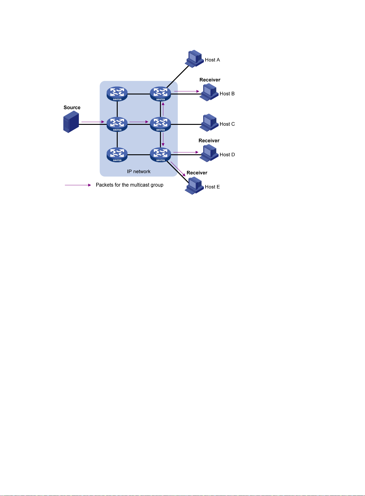
Figure 3 Multicast transmission
In Figure 3, the multicast source sends only one copy of the information to a multicast group. Host B,
Host D, and Host E, which are information receivers, must join the multicast group. The routers on
the network duplicate and forward the information based on the distribution of the group members.
Finally, the information is correctly delivered to Host B, Host D, and Host E.
To summarize, multicast has the following advantages:
• Advantages over unicast—Multicast data is replicated and distributed until it flows to the
farthest-possible node from the source. The increase of multicast re ceivers will not remarka bly
increase the load of the source or the usage of network resources.
• Advantages over broadcast—Multicast data is sent only to the receivers that need it. This
saves network bandwidth use and enhances network security. In addition, multicast data is not
confined to the same subnet.
Multicast features
• A multicast group is a multicast re ceiver set identified by an IP multicast address. Hosts must
join a multicast group to become members of the multicast group before they receive the
multicast data addressed to that multicast group. T ypically, a multicast source does not need to
join a multicast group.
• A multicast so urce is an information sen der. It can send data to multiple multicast groups at the
same time. Multiple multicast sources can send data to the same multicast group at the same
time.
• The group memberships are dynamic. Hosts can join or leave multicast groups at any time.
Multicast groups are not subject to geographic restrictions.
• Multicast routers or Layer 3 multicast devices are routers or Layer 3 switches that support Layer
3 multicast. They provide multicast routing and manage multicast group memberships on stub
subnets with attached group members. A multicast router itself can be a multicast group
member.
For a better understanding of the multicast concept, you can compare multicast transmission to the
transmission of TV programs.
3
Page 9

Table 1 Comparing TV program transmission and multicast transmission
TV program transmission Multicast transmission
A TV station transmits a TV program through a
channel.
A user tunes the TV set to the channel. A receiver joins the multicast group.
The user starts to watch the TV program
transmitted by the TV station on the channel.
The user turns off the TV set or tunes to another
channel.
A multicast source sends multicast data to a multicast
group.
The receiver starts to receive the multicast data sent by
the source to the multicast group.
The receiver leaves the multicast group or joins another
group.
Common notations in multicast
The following notations are commonly used in multicast transmission:
• (*, G)—Rendezvous point tree (RPT), or a multicast packet that any multicast source sends to
multicast group G. The asterisk (*) represents any multicast source, and "G" represents a
specific multicast group.
• (S, G)—Shortest path tree (SPT), or a multicast packet that multicast source "S" sends to
multicast group "G." "S" represents a specific multicast source, and "G" represents a specific
multicast group.
Multicast benefits and applications
Multicast benefits
• Enhanced efficiency—Reduces the processor load of information source servers and network
devices.
• Optimal performance—Reduces redundant traffic.
• Distributed application—Enables point-to-multipoint applications at the price of minimum
network resources.
Multicast applications
• Multimedia and streaming applications, such as web TV, web radio, and real-time video/audio
conferencing
• Communication for training and cooperative operation s, su ch as distance learning and
telemedicine
• Data warehouse and financial applications (stock quotes)
• Any other point-to-multipoint application for data distribution
Multicast models
Based on how the receivers treat the multicast sources, the multicast models include any-source
multicast (ASM), source-filtered multicast (SFM), and source-specific multicast (SSM).
ASM model
In the ASM model, any multicast sources can send information to a multicast group. Receivers can
join a multicast group and get multicast information addressed to that multicast group from any
4
Page 10

multicast sources. In this model, receivers do not know the positions of the multicast sources in
advance.
SFM model
The SFM model is derived from the ASM model. To a multicast source, the two models appear to
have the same multicast membership architecture.
The SFM model functionally extends the ASM model. The upper-layer software checks the source
address of received multicast packets and permits or denies multicast traffic from specific sources.
Therefore, receivers can receive the multicast data from only part of the multicast sources. To a
receiver, multicast sources are not all valid, but are filtered.
SSM model
The SSM model provides a transmission service that enables multicast receivers to specify the
multicast sources in which they are interested.
In the SSM model, receivers have already determined the locations of the multicast sources. This is
the main difference between the SSM model and the ASM model. In addition, the SSM model uses a
different multicast address range than the ASM/SFM model. Dedicated multicast forwarding paths
are established between receivers and the specified multicast sources.
IP multicast architecture
IP multicast addresses the following issues:
• Where should the multicast source transmit information to? (Multicast addressin g.)
• What receivers exist on the network? (Host registration.)
• Where is the multicast source that will provide data to the receivers? (Multicast source
discovery.)
• How is the information transmitted to the receivers? (Multicast routing.)
IP multicast is an end-to-end service. The multicast architecture involves the following parts:
• Addressing mechanism—A multicast source se nds information to a group of receivers
through a multicast address.
• Host registration—Multicast receivers can join and leave multicast groups dynamically. This
mechanism is the basis for management of group memberships.
• Multicast routing—A multicast distribution tree (a forwarding path tree for multicast data on the
network) is constructed for delivering multicast data from a multicast source to receivers.
• Multicast applications—A software system that supports multicast applications, such as video
conferencing, must be installed on multicast sources and multicast receivers. The TCP/IP stack
must support reception and transmission of multicast data.
Multicast addresses
IP multicast addresses
• IPv4 multicast addresses:
IANA assigns the Class D address block (224.0.0.0 to 239.255.255.255) to IPv4 multicast.
Table 2 Class D IP address blocks and description
Address block Description
224.0.0.0 to 224.0.0.255
Reserved permanent group addresses. The IP address
224.0.0.0 is reserved. Other IP addresses can be used by
routing protocols and for topology searching, protocol
maintenance, and so on. Table 3 lists comm
on permanent
5
Page 11

Address block Description
A
group addresses. A packet destined for an address in this
block will not be forwarded beyond the local subnet regardless
224.0.1.0 to 238.255.255.255
239.0.0.0 to 239.255.255.255
NOTE:
of the TTL value in the IP header.
Globally scoped group addresses. This block includes the
following types of designated group addresses:
• 232.0.0.0/8—SSM group addresses.
• 233.0.0.0/8—Glop group addresses.
Administratively scoped multicast addresses. These
addresses are considered locally unique rather than globall y
unique. You can reuse them in domains administered by
different organizations without causing conflicts. For more
information, see RFC 2365.
"Glop" is a mechanism for assigning multicast addresses between different ASs. By filling an
S number into the middle two bytes of 233.0.0.0, you get 255 multicast addresses for that AS.
For more information, see RFC 2770.
Table 3 Common permanent multicast group addresses
Address Description
224.0.0.1 All systems on this subnet, including hosts and routers.
224.0.0.2 All multicast routers on this subnet.
224.0.0.3 Unassigned.
224.0.0.4 DVMRP routers.
224.0.0.5 OSPF routers.
224.0.0.6 OSPF designated routers and backup designated routers.
224.0.0.7 Shared Tree (ST) routers.
224.0.0.8 ST hosts.
224.0.0.9 RIPv2 routers.
224.0.0.11 Mobile agents.
224.0.0.12 DHCP server/relay agent.
224.0.0.13 All Protocol Independent Multicast (PIM) routers.
224.0.0.14 RSVP encapsulation.
224.0.0.15 All Core-Based Tree (CBT) routers.
224.0.0.16 Designated SBM.
224.0.0.17 All SBMs.
224.0.0.18 VRRP.
• IPv6 multicast addresses:
6
Page 12
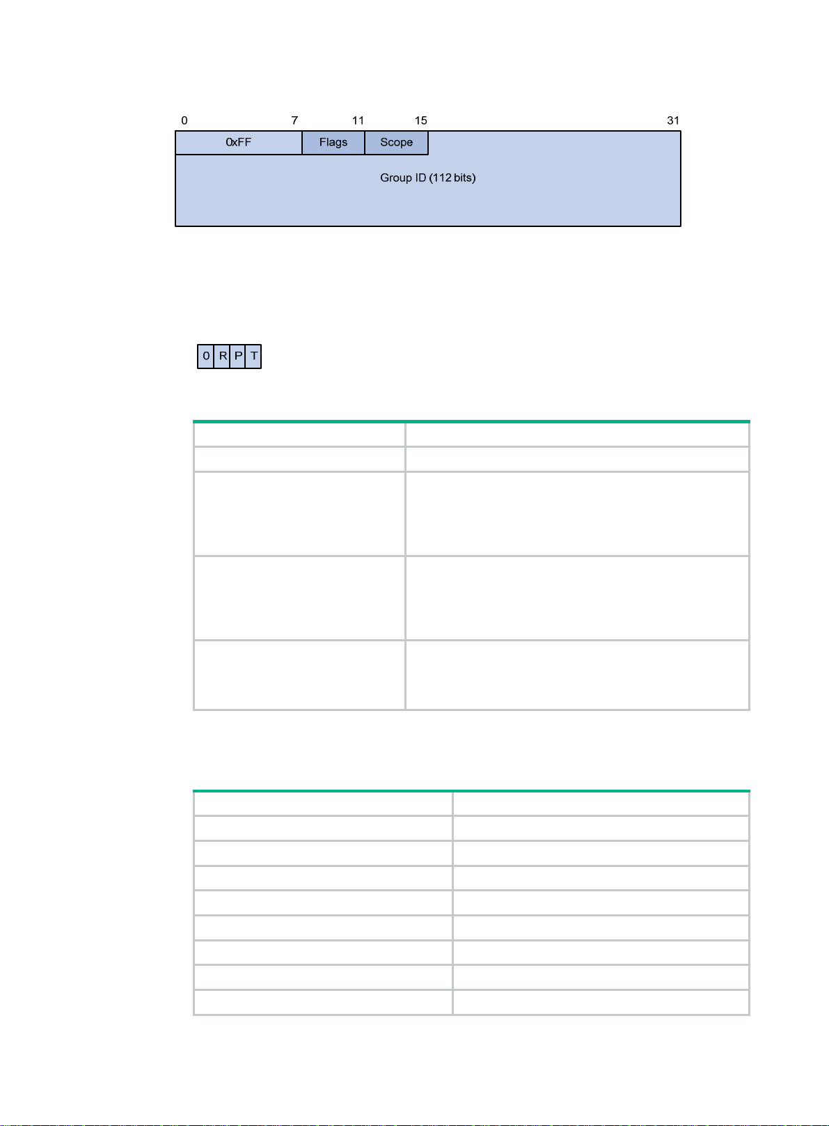
Figure 4 IPv6 multicast format
The following describes the fields of an IPv6 multicast address:
{ 0xFF—The most significant eight bits are 11111111.
{ Flags—The Flags field contains four bits.
Figure 5 Flags field format
Table 4 Flags field description
Bit Description
0 Reserved, set to 0.
• When set to 0, this address is an IPv6 multicast
address without an embedded RP address.
R
• When set to 1, this address is an IPv6 multicast
address with an embedded RP address. (The P and T
bits must also be set to 1.)
• When set to 0, this address is an IPv6 multicast
address not based on a unicast prefix.
P
• When set to 1, this address is an IPv6 multicast
address based on a unicast prefix. (The T bit must also
be set to 1.)
• When set to 0, this address is an IPv6 multicast
T
address permanently-assigned by IANA.
• When set to 1, this address is a transient or
dynamically assigned IPv6 multicast address.
Scope—The Scope field contains four bits, which represent the scope of the IPv6
{
internetwork for which the multicast traffic is intended.
Table 5 Values of the Scope field
Value Meaning
0, F Reserved.
1 Interface-local scope.
2 Link-local scope.
3 Subnet-local scope.
4 Admin-local scope.
5 Site-local scope.
6, 7, 9 through D Unassigned.
8 Organization-local scope.
7
Page 13
Value Meaning
E Global scope.
{ Group ID—The Group ID field contains 112 bits. It uniquely identifies an IPv6 multicast
group in the scope that the Scope field defines.
Ethernet multicast MAC addresses
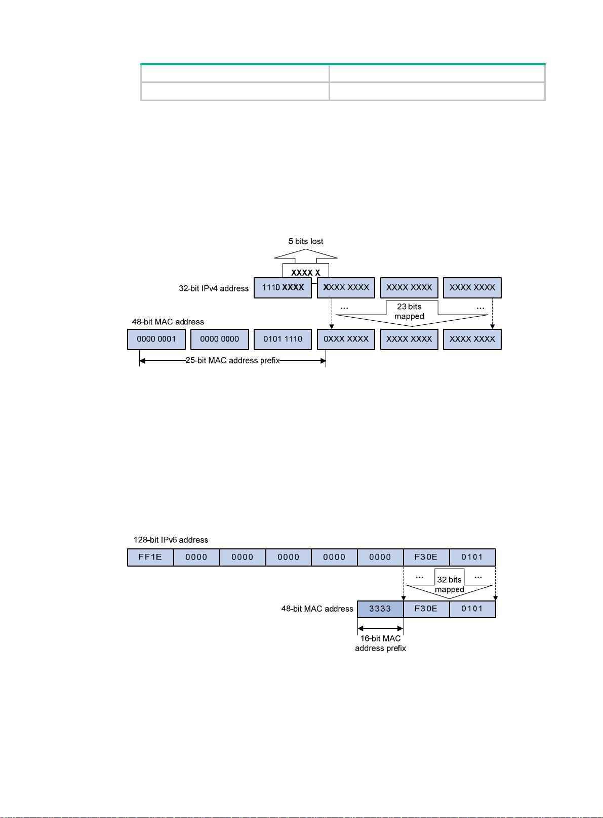
• IPv4 multicast MAC addresses:
As defined by IANA, the most significant 24 bits of an IPv4 multicast MAC address are
0x01005E. Bit 25 is 0, and the other 23 bits are the least significant 23 bits of an IPv4 multicast
address.
Figure 6 IPv4-to-MAC address mapping
The most significant four bits of an IPv4 multicast address are fixed at 1110. In an IPv4-to-MAC
address mapping, five bits of the IPv4 multicast address are lost. As a result, 32 IPv4 multicast
addresses are mapped to the same IPv4 multicast MAC address. Therefore, a device might
receive unwanted multicast data at Layer 2 processing, which needs to be filtered by the upper
layer.
• IPv6 multicast MAC addresses:
As defined by IANA, the most significant 16 bits of an IPv6 multicast MAC address are 0x3333.
The least significant 32 bits are mapped from the least significant 32 bits of an IPv6 multicast
address. Therefore, the problem of duplicate IPv6-to-MAC address mapping also arises like
IPv4-to-MAC address mapping.
Figure 7 An example of IPv6-to-MAC address mapping
Multicast protocols
Multicast protocols include the following categories:
• Layer 3 and Layer 2 multicast protocols:
8
Page 14
{ Layer 3 multicast refers to IP multicast working at the network layer.
Layer 3 multicast protocols—IGMP, MLD, PIM, IPv6 PIM, MSDP, MBGP, and IPv6
MBGP.
{ Layer 2 multicast refers to IP multicast working at the data link layer.
Layer 2 multicast protocols—IGMP snooping, MLD snooping, PIM snooping, IPv6 PIM
snooping, multicast VLAN, and IPv6 multicast VLAN.
• IPv4 and IPv6 multicast protocols:
{ For IPv4 networks—IGMP snooping, PIM snooping, multicast VLAN, IGMP, PIM, MSDP,
and MBGP.
{ For IPv6 networks—MLD snooping, IPv6 PIM snooping, IPv6 multicast VLAN, MLD, IPv6
PIM, and IPv6 MBGP.
This section provides only general descriptions about applications and functions of the Layer 2 and
Layer 3 multicast protocols in a network. For more information about Layer 2 multi cast protocols, see
the related chapters.
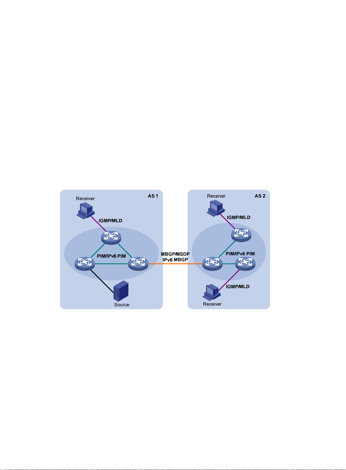
Layer 3 multicast protocols
In Figure 8, Layer 3 multicast protocols include multicast group management protocols an d multicast
routing protocols.
Figure 8 Positions of Layer 3 multicast protocols
• Multicast group management protocols:
Internet Group Management Protocol (IGMP) and Multicast Listener Discovery (MLD) protoc ol
are multicast group management protocols. Typically, they run between hosts and Layer 3
multicast devices that directly connect to the hosts to establish and maintain the multicast group
memberships.
• Multicast routing protocols:
A multicast routing protocol runs on Layer 3 multicast devices to establish and maintain
multicast routes and correctly and efficiently forward multicast packets. Multicast routes
constitute loop-free data transmission paths (also known as multicast distribution trees) from a
data source to multiple receivers.
In the ASM model, multicast routes include intra-domain routes and inter-domain routes.
{ An intra-domain multicast routing protocol discovers multicast sources and builds multicast
distribution trees within an AS to deliver multicast data to receivers. Among a variety of
mature intra-domain multicast routing protocols, PIM is most widely used. Based on the
9
Page 15
forwarding mechanism, PIM has dense mode (often referred to as "PIM-DM") and sparse
mode (often referred to as "PIM-SM").
{ An inter-domain multicast routing protocol is used for delivering multicast information
between two ASs. So far, mature solutions include Multicast Source Discovery Protocol
(MSDP) and MBGP. MSDP propagates multicast source information among different ASs.
MBGP is an extension of the MP-BGP for exchanging multicast routing information among
different ASs.
For the SSM model, multicast routes are not divided into intra-domain routes and inter-domain
routes. Because receivers know the position of the multicast source, channels established
through PIM-SM are sufficient for the transport of multicast information.
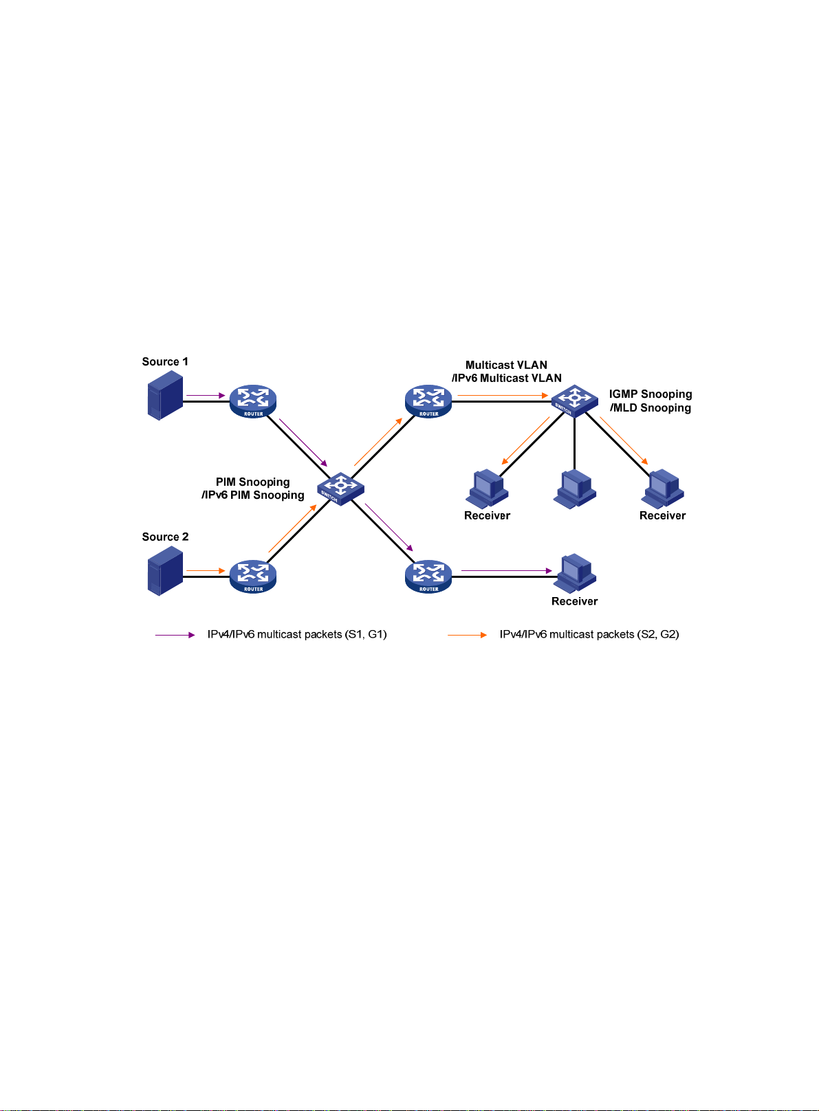
Layer 2 multicast protocols
In Figure 9, Layer 2 multicast protocols include IGMP snooping, MLD snooping, PIM snooping, IPv6
PIM snooping, multicast VLAN, and IPv6 multicast VLAN.
Figure 9 Positions of Layer 2 multicast protocols
• IGMP snooping and MLD snooping:
IGMP snooping and MLD snooping run on Layer 2 devices as multi ca st constraining
mechanisms to improve multicast forwarding efficiency. They generate Layer 2 multicast
forwarding tables by listening to IGMP or MLD messages exchanged between the hosts and
Layer 3 multicast devices. This effectively controls the flooding of multicast data in Layer 2
networks.
• PIM snooping and IPv6 PIM snooping:
PIM snooping and IPv6 PIM snooping run on Layer 2 devices. They work with IGMP snooping
or MLD snooping to analyze received PIM messages. Then, they add the ports that are
interested in specific multicast data to a PIM snooping routing entry or IPv6 PIM snooping
routing entry. In this way, multicast data can be forwarded to only the ports that are interested in
the data.
• Multicast VLAN and IPv6 multicast VLAN:
Multicast VLAN or IPv6 multicast VLAN runs on a Layer 2 device on a multicast network where
multicast receivers for the same group exist in different VLANs. With these protocols, the Layer
3 multicast device sends only one copy of multicast to the multicast VLAN or IPv6 multicast
VLAN on the Layer 2 device. This method avoids waste of network bandwidth an d extra burden
on the Layer 3 device.
10
Page 16

Multicast packet forwarding mechanism
In a multicast model, multicast receivers of a multicast group are usually located at different areas on
the network. They are identified by the same multicast group address. To deliver multicast packets to
these receivers, a multicast source encapsulates the multicast data in an IP packet with the multicast
group address as the destination address. Multicast routers on the forwarding paths forward
multicast packets that an incoming interface receives through multiple outgoing interfaces.
Compared to a unicast model, a multicast model is more complex in the following aspects:
• To ensure multicast packet transmission in the network, different routing tables are used for
multicast forwarding. These routing tables include unicast routing tables, routing tables for
multicast (for example, the MBGP routing table), and static multicast routing tables.
• To process the same multicast information from different peers received on dif fe rent interfaces,
the multicast device performs an RPF check on each multicast packet. The RPF check result
determines whether the packet will be forwarded or discarded. The RPF check mechanism is
the basis for most multicast routing protocols to implement multicast forwarding.
11
Page 17
Configuring IGMP snooping
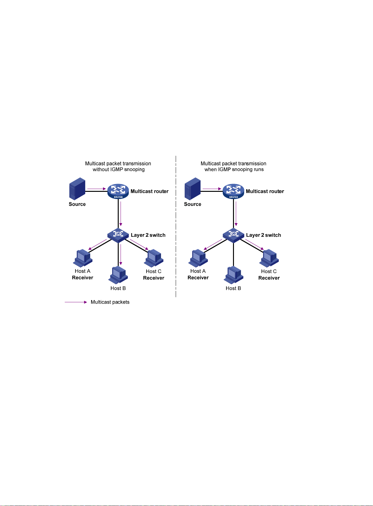
Overview
IGMP snooping runs on a Layer 2 device as a multicast constraining mechanism to improve
multicast forwarding efficiency. It creates Layer 2 multicast forw arding entries from IGMP packets
that are exchanged between the hosts and the router.
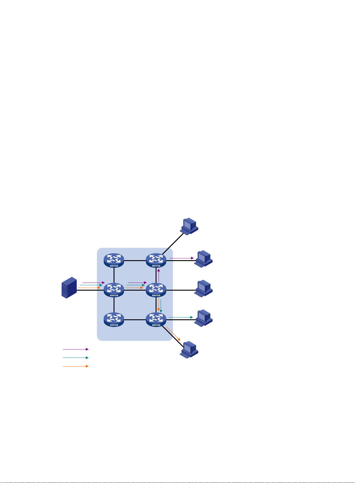
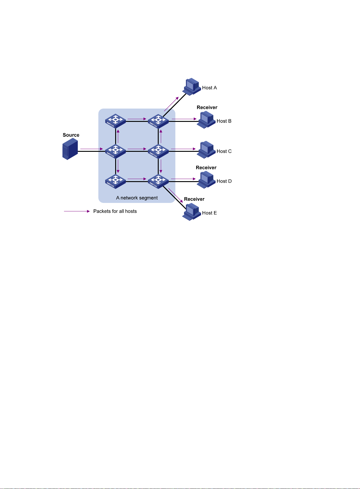
As shown in Figure 10,
packets to all hosts. When IGMP snooping is enable d, the Layer 2 device forwards multicast packets
of known multicast groups to only the receivers.
Figure 10 Multicast packet transmission without and with IGMP snooping
when IGMP snooping is not enabled, the Layer 2 device floods multicast
Basic IGMP snooping concepts
IGMP snooping related ports
As shown in Figure 11, IGMP snooping runs on Switch A and Switch B, and Host A and Host C are
receivers in a multicast group.
12
Page 18
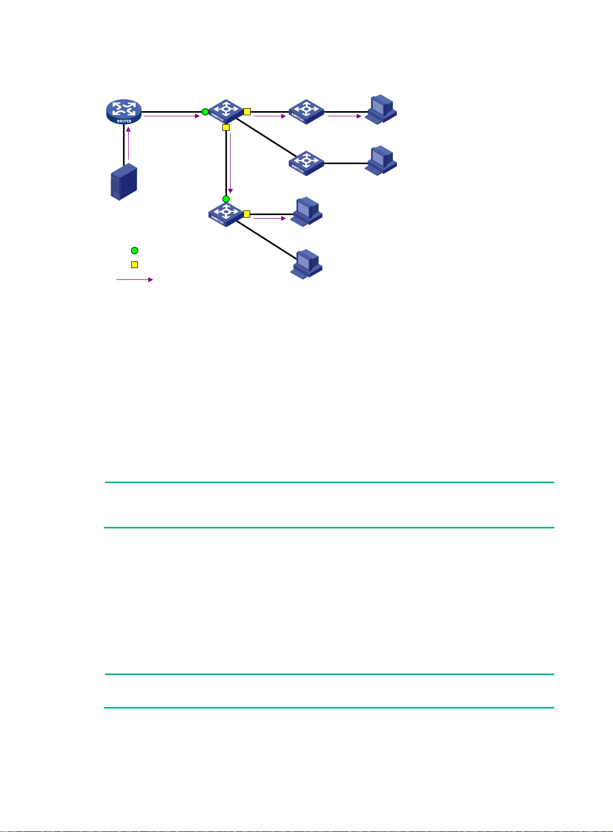
Figure 11 IGMP snooping related ports
Router A Switch A
GE1/0/1 GE1/0/2
GE1/0/3
GE1/0/1
Source
Switch B
Router port
Member port
Multicast packets
Receiver
GE1/0/2
Host C
Host D
Receiver
Host A
Host B
The following describes the ports involved in IGMP snooping:
• Router port—Layer 3 multicast device-side port. Layer 3 multicast devices include designated
routers (DRs) and IGMP queriers. In Figure 11, Gigab
itEthernet 1/0/1 of Switch A and
GigabitEthernet 1/0/1 of Switch B are the router ports. A Layer 2 dev ice records all its router
ports in a router port list.
Do not confuse the "router port" in IGMP snooping with the "routed interface" commonly known
as the "Layer 3 interface." The router port in IGMP snooping is a Layer 2 interface.
• Member port—Multicast receiver-side port. In Figure 11, Giga
bitEthernet 1/0/2 and
GigabitEthernet 1/0/3 of Switch A and GigabitEthernet 1/0/2 of Switch B are the member ports.
A Layer 2 dev ice records all its member ports in the IGMP snooping forwarding table.
Unless otherwise specified, router ports and member ports in this document include both static and
dynamic router ports and member ports.
NOTE:
When IGMP snooping is enabled, all ports that receive PIM hello messages or IGMP general
queries with the source addresses other than 0.0.0.0 are considered dynamic router ports.
Aging timers for dynamic ports in IGMP snooping
The following are aging timers for dynamic ports in IGMP snooping:
• Dynamic router port aging timer—The Layer 2 device starts this timer for a port that receives
an IGMP general query with the source address other than 0.0.0.0 or a PIM hello message. If
the port does not receive either of these messages before the timer expires, the Layer 2 devi ce
removes the port from its router port list.
• Dynamic member port aging timer—The Layer 2 device starts this timer for a port that
receives an IGMP report. If the port does not receive a report before the timer expires, the Layer
2 device removes the port from the IGMP snooping forwarding entries.
NOTE:
In IGMP snooping, only dynamic ports age out. Static ports never age out.
13
Page 19

How IGMP snooping works
The ports in this section are dynamic ports. For information about how to configure and remove static
ports, see "Configuring static ports."
messages types include general query, IGMP report, and leave message. An IGMP
IGMP
snooping-enabled Layer 2 device performs differently depen ding on the message.
General query
The IGMP querier periodically sends IGMP general queries to all hosts and routers on the local
subnet to check for the existence of multicast group members.
After receiving an IGMP general query, the Layer 2 device forwards the query to all ports in the VLAN
except the receiving port. The Layer 2 device also performs one of the following actions:
• If the receiving port is a dynamic router port in the router port list, the Layer 2 device restarts the
aging timer for the port.
• If the receiving port does not exist in the router port list, the Layer 2 device adds the port to the
router port list. It also starts an aging timer for the port.
IGMP report
A host sends an IGMP report to the IGMP querier for the following purpo ses:
• Responds to queries if the host is a multicast group member.
• Applies for a multicast group membership.
After receiving an IGMP report from a host, the Layer 2 device forwards the report through all the
router ports in the VLAN. It also resolves the address of the reported multicast group, and looks up
the forwarding table:
• If no match is found, the Layer 2 device creates a forwarding entry with the receiving port as an
outgoing interface to the forwarding entry . It also marks the receiving port as a dynamic member
port and starts an aging timer for the port.
• If a match is found but the receiving port is not in the forwarding entry, the Layer 2 device adds
the port as an outgoing interface to the forwarding entry. It also marks the receiving port as a
dynamic member port and starts an aging timer for the port.
• If a match is found and the receiving port is in the forwarding entry, the Layer 2 device restarts
the aging timer for the port.
In an application with a multicast group policy configured on an IGMP snooping-enabled Layer 2
device, when a user requests a multicast program, the user's host initiates an IGMP report. After
receiving this report, the Layer 2 device resolves the multicast group address in the report and
performs ACL filtering on the report. If the report passes ACL filtering, the Layer 2 device creates an
IGMP snooping forwarding entry with the receiving port as an outgoing interface. If the report does
not pass ACL filtering, the Layer 2 device drops this report, which means the receiver does not
successfully join the multicast group and cannot retrieve the program.
A Layer 2 device does not forward an IGMP report through a non-router port because of the IGMP
report suppression mechanism.
Leave message
An IGMPv1 host does not send any leave messages when it leaves a multicast group. The Layer 2
device cannot immediately update the status of the port that connects to the receiver host. In this
case, it does not remove the port from the outgoing interface list in the associated forwarding entry
until the aging timer for the multicast group on the port expires.
An IGMPv2 or IGMPv3 host sends an IGMP leave message when it leaves a multicast group.
When the Layer 2 device receives an IGMP leave message on a dynamic mem ber port, the Layer 2
device first examines whether a forwarding entry matches the group address in the message.
• If no match is found, the Layer 2 device discards the IGMP leave message.
14
Page 20

• If a match is found but the receiving port is not in the forwarding entry, the Layer 2 device
discards the IGMP leave message.
• If a match is found and the receiving port is in the forwarding entry, the Layer 2 device forwards
the leave message to all router ports in the VLAN. The Layer 2 device does not immediately
remove the port from the forwarding entry for that group. Instead, it adjusts the aging timer for
the port.
After receiving the IGMP leave message, the IGMP querier resolves the multicast group address in
the message. Then, it sends an IGMP group-specific query to the multicast group through the port
that received the leave message.
After receiving the IGMP group-specific query, the Layer 2 device forwards the query through all its
router ports in the VLAN and all member ports of the multicast group. Then, it waits for the
responding IGMP reports from the directly connected receivers. For the dynamic member port that
received the leave message, the Layer 2 device also performs one of the following actions:
• If the port receives an IGMP report before the aging timer expires, the Layer 2 device restarts
the aging timer for the port.
• If the port does not receive an IGMP report when the aging timer expires, the Layer 2 device
removes the port from the forwarding entry for the multicast group.
Protocols and standards
RFC 4541, Considerations for Internet Group Management Protocol (IGMP) and Multicast Listener
Discovery (MLD) Snooping Switches
IGMP snooping configuration task list
Tasks at a glance
Configuring basic IGMP snooping features:
• (Required.) Enabling IGMP snooping
• (Optional.) Specifying an IGMP snooping version
• (Optional.) Setting the maximum number of IGMP snooping forwarding entries
Configuring IGMP snooping port features:
• (Optional.) Setting aging timers fo
• (Optional.) Configuring static ports
• (Optiona
• (Optional.) Enabling fast-leave processing
• (Optiona
Configuring the IGMP snooping querier:
• (Optional.) Enabling the IGMP snooping querier
• (Optiona
Configuring parameters for IGMP messages:
• (Optional.) Configuring source IP addresses for IGMP messages
• (Optiona
l.) Configuring a port as a simulated member host
l.) Disabling a port from becoming a dynamic router port
l.) Configuring parameters for IGMP queries and responses
l.) Setting the 802.1p priority for IGMP messages
r dynamic ports
15
Page 21

Tasks at a glance
Configuring IGMP snooping policies:
• (Optional.) Configuring a multicast group policy
• (Optional.) Configuring multicast source port filtering
• (Optional.) Enabling dropping unknown multicast data
• (Optional.) Enabling IGMP report suppression
• (Optional.) Setting the maximum number of multicast groups on a port
• (Optional.) Enabling the multicast group re
placement feature
The IGMP snooping configurations made on Layer 2 aggregate interfaces do not interfere with the
configurations made on member ports. In addition, the configurations made on Layer 2 aggregate
interfaces do not take part in aggregation calculations. The configuration made on a member port of
the aggregate group takes effect after the port leaves the aggregate group.
Configuring basic IGMP snooping features
Before you configure basic IGMP snooping features, complete the following tasks:
• Configure the associated VLANs.
• Determine the IGMP snooping version.
• Determine the IGMP last member query interval.
• Determine the maximum response time for IGMP general queries.
Enabling IGMP snooping
When you enable IGMP snooping, follow these guidelines:
• You must enable IGMP snooping globally before you enable it for a VLAN.
• IGMP snooping for a VLAN works only on the member ports in that VLAN.
• You can enable IGMP snooping for the specified VLANs in IGMP-snooping view or for a VLAN
in VLAN view. For a VLAN, the configuration in VLAN view has the same priority as the
configuration in IGMP-snooping view, and the most recent configuration takes effect.
To enable IGMP snooping for a VLAN in IGMP-snooping view:
Step Command Remarks
1. Enter system view.
2. Enable IGMP snooping
globally and enter
IGMP-snooping view.
3. Enable IGMP snooping for
specified VLANs.
To enable IGMP snooping for a VLAN in VLAN view:
Step Command Remarks
1. Enter system view.
2. Enable IGMP snooping
globally and enter
IGMP-snooping view.
3. Return to system view.
system-view
igmp-snooping
enable vlan
system-view
igmp-snooping
quit
vlan-list
N/A
By default, IGMP snooping is globally
disabled.
By default, IGMP snooping is d isabled
for a VLAN.
N/A
By default, IGMP snooping is
globally disabled.
N/A
16
Page 22

Step Command Remarks
4. Enter VLAN view.
5. Enable IGMP snooping for
the VLAN.
vlan
igmp-snooping enable
vlan-id
Specifying an IGMP snooping version
Different IGMP snooping version s ca n process different versions of IGMP messages.
• IGMPv2 snooping can process IGMPv1 and IGMPv2 messages, but it floods IGMPv3
messages in the VLAN instead of processing them.
• IGMPv3 snooping can process IGMPv1, IGMPv2, and IGMPv3 messages.
If you change IGMPv3 snooping to IGMPv2 snooping, the switch performs the following operations:
• Clears all IGMP snooping forwarding entries that are dynamically added.
• Keeps static IGMPv3 snooping forwarding entries (*, G).
• Clears static IGMPv3 snooping forwarding entries (S, G), which will be resto re d when IGMP
snooping is switched back to IGMPv3 snooping.
N/A
By default, IGMP snooping is
disabled for a VLAN.
For more information about static IGMP snooping forwarding entries, se e "Conf iguring static ports."
You can specify the version for the specified VLANs in IGMP-snooping view or for a VLAN in VLAN
view. For a VLAN, the configuration in VLAN view has the same priority as the configuration in
IGMP-snooping view, and the most recent configuration takes effect.
To specify an IGMP snooping version for a VLAN in IGMP-snooping view:
Step Command Remarks
1. Enter system view.
2. Enable IGMP snooping
globally and enter
IGMP-snooping view.
3. Specify an IGMP snooping
version for the specified
VLANs.
To specify an IGMP snooping version for a VLAN in VLAN view:
system-view
igmp-snooping
version
vlan-list
N/A
version-number
vlan
N/A
The default setting is 2.
Step Command Remarks
1. Enter system view.
2. Enter VLAN view.
3. Specify an IGMP snooping
version for the VLAN.
system-view
vlan
vlan-id
igmp-snooping version
version-number
N/A
N/A
The default setting in a VLAN is 2.
Setting the maximum number of IGMP snooping forwarding entries
You can modify the maximum number of IGMP snooping forwarding entries, including dynamic
entries and static entries. When the number of forwarding entries on the switch reaches the upper
limit, the switch does not automatically remove any existing entries. As a best practice, manually
remove some entries to allow new entries to be created.
17
Page 23

To set the maximum number of IGMP snooping forwarding entries:
Step Command Remarks
1. Enter system view.
2. Enter IGMP-snooping view.
3. Set the maximum number of
IGMP snooping forwarding
entries.
system-view
igmp-snooping
entry-limit
N/A
limit
N/A
The default setting is
4294967295.
Configuring IGMP snooping port features
Before you configure IGMP snooping port features, complete the following tasks:
• Enable IGMP snooping for the VLAN.
• Determine the aging timer for dynamic router ports.
• Determine the aging timer for dynamic member ports.
• Determine the addresses of the multicast group and multicast source.
Setting aging timers for dynamic ports
When you set aging timers for dynamic ports, follow these guidelines:
• If the memberships of multicast groups frequently change, you can set a relatively small value
for the aging timer of the dynamic member ports. If the membership s of multica st groups rarely
change, you can set a relatively large value.
• If a dynamic router port receives a PIMv2 hello message, the aging timer value for the port is
specified by the hello message. In this case, the router-aging-time or igmp-snooping
router-aging-time command does not take effect on the port.
• You can set the timers globally for all VLANs in IGMP-snooping view or for a VLAN in VLAN
view. For a VLAN, the VLAN-specific configuration takes priority over the global configuration.
Setting the aging timers for dynamic ports globally
Step Command Remarks
4. Enter system view.
5. Enter IGMP-snooping view.
6. Set the aging timer for dynamic
router ports globally.
7. Set the global aging timer for
dynamic member ports globally.
system-view
igmp-snooping
router-aging-time
host-aging-time
Setting the aging timers for dynamic ports in a VLAN
N/A
N/A
interval
interval
The default setting is 260
seconds.
The default setting is 260
seconds.
Step Command Remarks
1. Enter system view.
2. Enter VLAN view.
3. Set the aging timer for
dynamic router ports in the
VLAN.
4. Set the aging timer for
system-view
vlan
vlan-id
igmp-snooping
router-aging-time
igmp-snooping host-aging-time
N/A
interval
18
N/A
The default setting is 260
seconds.
The default setting is 260
Page 24

Step Command Remarks
dynamic member ports in the
VLAN.
Configuring static ports
You can configure the following types of static ports:
• Static member port—When you configure a port as a static member port for a multicast group,
all hosts attached to the port will receive multicast data for the group.
The static member port does not respond to IGMP queries. When you complete or cancel this
configuration on a port, the port does not send an unsolicited IGMP report or leave message.
• Static router port—When you configure a port as a static router port for a multicast group, all
multicast data for the group received on the port will be forwarded.
Static member ports and static router ports never age out. To remove such a port, use the undo
igmp-snooping static-group or undo igmp-snooping static-router-port command.
To configure static ports:
Step Command Remarks
1. Enter system view.
2. Enter Layer 2 Ethernet
interface view or Layer 2
aggregate interface view.
3. Configure the port as a static
port.
interval
system-view
interface
interface-number
• Configure the port as a static
member port:
igmp-snooping
static-group group-address
[ source-ip source-address ]
vlan vlan-id
• Configure the port as a static
router port:
igmp-snooping
static-router-port vlan
vlan-id
N/A
interface-type
seconds.
N/A
By default, a port is not a static
member port or a static router
port.
Configuring a port as a simulated member host
When a port is configured as a simulated member host, it is equivalent to an independent host in the
following ways:
• It sends an unsolicited IGMP report when you complete the config uration.
• It responds to IGMP general queries with IGMP reports.
• It sends an IGMP leave message when you cancel the configuration.
The version of IGMP running on the simulated member host is the same as the version of IGMP
snooping running on the port. The port ages out in the same way as a dynamic member port.
To configure a port as a simulated member host:
Step Command Remarks
1. Enter system view.
2. Enter Layer 2 Ethernet
system-view
interface
interface-type
19
N/A
N/A
Page 25

Step Command Remarks
interface view or Layer 2
aggregate interface view.
interface-number
3. Configure the port as a
simulated member host.
igmp-snooping host-join
group-address [
source-address ]
Enabling fast-leave processing
This feature enables the switch to immediately remove a port from the forwarding entry for a
multicast group when the port receives a leave massage.
Configuration restrictions and guidelines
When you enable fast-leave processing, follow these restrictio ns and guidelines:
• Do not enable fast-leave processing on a port that has multiple receiver hosts in a VLAN. If
fast-leave processing is enabled, the remaining receivers cannot receive multicast data for a
group after a receiver leaves that group.
• You can enable fast-leave processing globally for all ports in IGMP-snooping view or for a port
in interface view. For a port, the port-specific configuration takes priority over the global
configuration.
Enabling fast-leave processing globally
Step Command Remarks
1. Enter system view.
system-view
source-ip
vlan
vlan-id
N/A
By default, the port is not a
simulated member host.
2. Enter IGMP-snooping view.
3. Enable fast-leave processing
globally.
igmp-snooping
fast-leave [ vlan
vlan-list ]
N/A
By default, fast-leave processing
is disabled globally.
Enabling fast-leave processing on a port
Step Command Remarks
1. Enter system view.
2. Enter Layer 2 Ethernet
interface view or Layer 2
aggregate interface view.
3. Enable fast-leave processing
on the port.
system-view
interface
interface-number
igmp-snooping fast-leave [ vlan
vlan-list ]
N/A
interface-type
N/A
By default, fast-leave processing
is disabled on a port.
Disabling a port from becoming a dynamic router port
A receiver host might send IGMP general queries or PIM hello messages for testing purposes. On
the Layer 2 device, the port that receives either of the messages becomes a dynamic router port.
Before the aging timer for the port expires, the following problems might occur:
• All multicast data for the VLAN to which the port belongs flows to the port. Then, the port
forwards the data to attached receiver hosts. The receiver hosts will receive multicast data that
it does not want to receive.
• The port forwards the IGMP general queries or PIM hello messages to its upstream multicast
routers. These messages might affect the multicast routing protocol state (such as the IGMP
querier or DR election) on the multicast routers. This might further cause network interruption.
20
Page 26

To solve these problems, you can disable a port from becoming a dynamic router port. This also
improves network security and the control over receiver hosts.
To disable a port from becoming a dynamic router port:
Step Command Remarks
1. Enter system view.
2. Enter Layer 2 Ethernet
interface view or Layer 2
aggregate interface view.
system-view
interface
interface-number
interface-type
N/A
N/A
3. Disable the port from
becoming a dynamic router
port.
igmp-snooping
router-port-deny [ vlan
vlan-list ]
By default, a port can become a
dynamic router port.
This configuration does not affect
the static router port configuration.
Configuring the IGMP snooping querier
This section describes how to configure an IGMP snoopin g querier.
Configuration prerequisites
Before you configure the IGMP snooping querier for the VLAN, complete the following tasks:
• Enable IGMP snooping for the VLAN.
• Determine the IGMP general query interval.
• Determine the IGMP last member query interval.
• Determine the maximum response time for IGMP general queries.
Enabling the IGMP snooping querier
This feature enables the switch to periodically send IGMP general queries to establish and maintain
multicast forwarding entries at the data link Layer . You can configure an IGMP snooping querier on a
network without Layer 3 multicast devices.
Configuration guidelines
When you enable the IGMP snooping querier, do not configure an IGMP snooping querier on a
multicast network that runs IGMP. An IGMP snooping querier does not take part in IGMP querier
elections. However, it might affect IGMP querier ele ctions if it sends IGMP general queries with a low
source IP address.
Configuration procedure
To enable the IGMP snooping querier for a VLAN:
Step Command Remarks
1. Enter system view.
2. Enter VLAN view.
3. Enable the IGMP snooping
querier.
system-view
vlan-id
21
vlan
igmp-snooping querier
N/A
N/A
By default, the IGMP snooping
querier is disabled.
Page 27

Configuring parameters for IGMP queries and responses
CAUTION:
To avoid mistakenly deleting multicast group members, make sure the IGMP general query interva l
is greater than the maximum response time for IGMP general queries.
You can modify the IGMP general query interval based on the actual condition of the network.
A receiver host starts a timer for each multicast group that it has joined when it receives an IGMP
query (general query or group-specific query). This timer is initialized to a random value in the range
of 0 to the maximum response time advertised in the IGMP query . When the timer value decreases to
0, the host sends an IGMP report to the multicast group.
To speed up the response of hosts to IGMP queries and to avoid simultaneous timer expirations
which cause IGMP report traffic bursts, you must correctly set the maximum response time.
• The maximum response time for IGMP general queries is set by the max-response-time
command.
• The maximum response time for IGMP group-specific queries equals the IGMP last member
query interval, which is set by the last-member-query-interval interval command.
You can configure the parameters globally for all VLANs in IGMP-snooping view or for a VLAN in
VLAN view. For a VLAN, the VLAN-speci fic configuration takes pri ority over the global configuration.
Configuring the global parameters for IGMP queries and responses
Step Command Remarks
1. Enter system view.
2. Enter IGMP-snooping view.
3. Set the maximum response
time for IGMP general
queries.
4. Set the IGMP last member
query interval.
system-view
igmp-snooping
max-response-time
last-member-query-interval
interval
interval
Configuring the parameters for IGMP queries and responses in a VLAN
Step Command Remarks
1. Enter system view.
2. Enter VLAN view.
3. Set the IGMP general query
interval in the VLAN.
4. Set the maximum response
time for IGMP general
queries in the VLAN.
5. Set the IGMP last member
query interval in the VLAN.
system-view
vlan
vlan-id N/A
igmp-snooping query-interval
igmp-snooping max-response-time
interval
igmp-snooping
last-member-query-interval
interval
interval
N/A
N/A
The default setting is 10
seconds.
The default setting is 1
second.
N/A
The default setting is 125
seconds.
The default setting is 10
seconds.
The default setting is 1
second.
Configuring parameters for IGMP messages
This section describes how to configure parameters for IGMP messages.
22
Page 28

Configuration prerequisites
Before you configure parameters for IGMP messages in a VLAN, complete the following tasks:
• Enable IGMP snooping for the VLAN.
• Determine the source IP address of IGMP general queries.
• Determine the source IP address of IGMP group-specific queries.
• Determine the source IP address of IGMP reports.
• Determine the source IP address of IGMP leave messages.
• Determine the 802.1p priority of IGMP messages.
Configuring source IP addresses for IGMP messages
A Layer 2 device does not enlist the port that receives an IGMP query whose source IP address is
0.0.0.0 on a port as a dynamic router port. This might prevent multicast forwarding entries from being
correctly created at the data link layer and eventually cause multicast traffic forwarding failures.
To avoid this problem, when a Layer 2 device acts as the IGMP snooping querier, you can configure
a non-all-zero IP address as the source IP addre ss of IGMP queries. You can also change the source
IP address of IGMP messages sent by a simulated member host or an IGMP snooping proxy.
Changing the source address of IGMP queries might affect the IGMP querier election within the
subnet.
To configure source IP addresses for IGMP messages in a VLAN:
Step Command Remarks
1. Enter system view.
2. Enter VLAN view.
3. Configure the source IP
address for IGMP
general queries.
4. Configure the source IP
address for IGMP
group-specific queries.
system-view
vlan-id
vlan
igmp-snooping
general-query source-ip
ip-address
igmp-snooping
special-query source-ip
ip-address
N/A
N/A
The default setting is the IP address of the
current VLAN interface. If the current
VLAN interface does not have an IP
address, the source IP address is 0.0.0.0.
By default, the source IP address of IGMP
group-specific queries is one of the
following:
• The source address of IGMP
group-specific queries if the IGMP
snooping querier has received IGMP
general queries.
• The IP address of the current VLAN
interface if the IGMP snooping
querier does not receive an IGMP
general query.
• 0.0.0.0 if the IGMP snooping querier
does not receive an IGMP general
query and the current VLAN
interface does not have an IP
address.
5. Configure the source IP
address for IGMP
reports.
6. Configure the source IP
address for IGMP leave
igmp-snooping report
source-ip
igmp-snooping leave
source-ip
ip-address
ip-address
23
The default setting is the IP address of the
current VLAN interface. If the current
VLAN interface does not have an IP
address, the source IP address is 0.0.0.0.
The default setting is the IP address of the
current VLAN interface. If the current
Page 29

Step Command Remarks
messages. VLAN interface does not have an IP
address, the source IP address is 0.0.0.0.
Setting the 802.1p priority for IGMP messages
When congestion occurs on outgoing ports of the Layer 2 device, it forwards IGMP messages in their
802.1p priority order, from highest to lowest. You can assign a higher 802.1p priority to IGMP
messages that are created or forwarded by the switch.
You can set the 802.1p priority globally for all VLANs in IGMP-snooping view or for a VLAN in VLAN
view. For a VLAN, the VLAN-specific configuration takes priority over the global configuration.
Setting the 802.1p priority for IGMP messages globally
Step Command Remarks
1. Enter system view.
2. Enter IGMP-snooping view.
3. Set the 802.1p priority for
IGMP messages.
system-view
igmp-snooping
dot1p-priority
N/A
N/A
priority-number The default setting is 0.
Setting the 802.1p priority for IGMP messages in a VLAN
Step Command Remarks
1. Enter system view.
2. Enter VLAN view.
3. Set the 802.1p priority for
IGMP messages in the
VLAN.
system-view
vlan
vlan-id N/A
igmp-snooping dot1p-priority
priority-number
N/A
The default setting is 0.
Configuring IGMP snooping policies
Before you configure IGMP snooping policies, complete the following tasks:
• Enable IGMP snooping for the VLAN.
• Determine the ACLs to be used by multicast group policies.
• Determine the maximum number of multicast groups that a port can join.
Configuring a multicast group policy
This feature enables the switch to filter IGMP reports by using an ACL that specifies the multicast
groups and the optional sources. It is used to control the multicast groups that receiver hosts can
join.
Configuration guidelines
When you configure a multicast group policy, follow these guidelines:
• This configuration takes effect only on the multicast groups that a port joins dynamically.
• You can configure a multicast group policy globally for all ports in IGMP-snooping view or for a
port in interface view. For a port, the port-specific configuration takes priority over the global
configuration.
24
Page 30

Configuring a multicast group policy globally
Step Command Remarks
1. Enter system view.
2. Enter IGMP-snooping view.
system-view
igmp-snooping
N/A
N/A
3. Configure a multicast group
policy globally.
group-policy
vlan-list ]
acl-number [
vlan
Configuring a multicast group policy on a port
Step Command Remarks
1. Enter system view.
2. Enter Layer 2 Ethernet
interface view or Layer 2
aggregate interface view.
3. Configure a multicast group
policy on the port.
system-view
interface
interface-number
igmp-snooping group-policy
acl-number [
N/A
vlan-list ]
interface-type
vlan
Configuring multicast source port filtering
This feature enables the switch to discard all multicast data packets and to a ccept multicast protocol
packets. You can enable this feature on ports that connect only to multicast receivers.
You can enable this feature for the specified ports in IGMP-snooping view or for a port in interface
view. For a port, the configuration in interface view has the same priority as the configuration in
IGMP-snooping view, and the most recent configuration takes effect.
By default, no multicast group
policies exist. Hosts can join all
multicast groups.
N/A
By default, no multicast group
policies exist. Hosts can join all
multicast groups.
Configuring multicast source port filtering globally
Step Command Remarks
1. Enter system view.
2. Enter IGMP-snooping view.
3. Enable multicast source port
filtering.
system-view
igmp-snooping
source-deny port
interface-list
Configuring multicast source port filtering on a port
Step Command Remarks
1. Enter system view.
2. Enter Layer 2 Ethernet
interface view.
3. Enable multicast source port
filtering.
system-view
interface
interface-number
igmp-snooping source-deny
interface-type
Enabling dropping unknown multicast data
This feature enables the switch to drop all unknown multicast data. Unknown multicast data refers to
multicast data for which no forwarding entries exist in the IGMP snooping forwarding table.
N/A
N/A
By default, multicast source port
filtering is disabled.
N/A
N/A
By default, the multicast source
port filtering is disabled.
25
Page 31

To enable dropping unknown multicast data for a VLAN:
Step Command Remarks
1. Enter system view.
2. Enter VLAN view.
system-view
vlan
vlan-id
N/A
N/A
3. Enable dropping unknown
multicast data for the VLAN.
igmp-snooping drop-unknown
By default, this feature is disabled.
Unknown multicast data is flooded
in the VLAN to which the data
belongs.
Enabling IGMP report suppression
This feature enables the switch to forward only the first IGMP report for a multicast group to its
directly connected Layer 3 device. Other reports for the same group in the same query interval are
discarded. This reduces the multicast traffic.
To enable IGMP report suppression:
Step Command Remarks
1. Enter system view.
2. Enter IGMP-snooping view.
3. Enable IGMP report
suppression.
system-view
igmp-snooping
report-aggregation
N/A
N/A
By default, IGMP report suppression is
enabled.
Setting the maximum number of multicast groups on a port
You can set the maximum number of multicast groups on a port to regulate the port traffic.
When you set the maximum number of multicast groups on a port, follow these guidelines:
• This configuration takes effect only on the multicast groups that a port joins dynamically.
• If the number of multicast groups on a port exceeds the limit, the system removes all the
forwarding entries related to that port from the IGMP snooping forwarding table. The receiver
hosts attached to that port can join multicast groups again before the number of multicast
groups on the port reaches the limit.
To set the maximum number of multicast groups on a port:
Step Command Remarks
1. Enter system view.
2. Enter Layer 2 Ethernet
interface view or Layer 2
aggregate interface view.
3. Set the maximum number of
multicast groups on a port.
system-view
interface
interface-number
igmp-snooping group-limit
vlan
[
N/A
interface-type
vlan-list ]
limit
N/A
The default setting is
4294967295.
Enabling the multicast group replacement feature
This feature enables the switch to replace an existing multicast group with a newly joined multicast
group when the number of groups exceeds the upper limit. This feature is typically used in the
26
Page 32

channel switching application. Without this feature, the switch discards IGMP reports for new groups,
and the user cannot change to the new channel.
Configuration restrictions and guidelines
When you enable the multicast group replacement feature, follow these guidelines:
• This configuration takes effect only on the multicast groups that a port joins dynamically.
• Y ou can enable this feature globally for all ports in IGMP-snooping view or for a port in interface
view. For a port, the port-specific configuration takes priority over the global configuration.
Configuration procedure
To enable the multicast group replacement feature globally:
Step Command Remarks
1. Enter system view.
2. Enter IGMP-snooping view.
system-view
igmp-snooping
N/A
N/A
3. Enable the multicast group
replacement feature globally.
To enable the multicast group replacement feature on a port:
overflow-replace [ vlan
vlan-list ]
By default, the multicast group
replacement feature is disabled
globally.
Step Command Remarks
1. Enter system view.
2. Enter Layer 2 Ethernet
interface view or Layer 2
aggregate interface view.
3. Enable multicast group
replacement feature on a
port.
system-view
interface
interface-number
igmp-snooping
overflow-replace [ vlan
N/A
interface-type
vlan-list ]
N/A
By default, the multicast group
replacement feature is disabled
on a port.
Displaying and maintaining IGMP snooping
Execute display commands in any view and reset commands in user view.
Task Command
Display IGMP snooping status.
display igmp-snooping
global
[
|
vlan
vlan-id ]
Display dynamic IGMP snooping group
entries.
Display static IGMP snooping group
entries.
Display dynamic router port information.
Display static router port information.
Display statistics for the IGMP messages
learned through IGMP snooping.
display igmp-snooping group
source-address ] * [
slot-number ]
display igmp-snooping static-group
source-address ] * [
slot-number ]
display igmp-snooping router-port
slot-number ]
display igmp-snooping static-router-port
slot
[
slot-number ]
display igmp-snooping statistics
27
vlan
vlan
[ group-address |
vlan-id ] [
vlan-id ] [
verbose
[ group-address |
verbose
vlan
[
slot
] [
slot
] [
vlan-id ] [
vlan
[
vlan-id ]
slot
Page 33

Task Command
Display information about Layer 2 IP
multicast groups.
display l2-multicast ip
source-address ] * [
[
vlan
group
group-address |
vlan-id ] [
slot
slot-number ]
source
Display information about Layer 2 IP
multicast group entries.
Display information about Layer 2 MAC
multicast groups.
Display information about Layer 2 MAC
multicast group entries.
Delete dynamic IGMP snooping group
entries.
Delete dynamic router ports.
Clear statistics for the IGMP messages
learned through IGMP snooping.
display l2-multicast ip forwarding
source
source-address ] * [
display l2-multicast mac
slot-number ]
display l2-multicast mac forwarding
vlan-id ] [
reset igmp-snooping group
[ source-address ] |
reset igmp-snooping router-port
reset igmp-snooping statistics
slot
slot-number ]
all
vlan
[ mac-address ] [
{ group-address
vlan
} [
vlan-id ]
group
[
vlan-id ] [
{
slot
[ mac-address ] [
all
vlan
|
group-address |
slot-number ]
vlan
vlan-id ] [
vlan-id }
slot
vlan
IGMP snooping configuration examples
Group policy and simulated joining configuration example (for VLANs)
Network requirements
As shown in Figure 12, Router A runs IGMPv2 and a cts as the IGM P querier. Switch A runs IGMPv2
snooping.
Configure a multicast group policy to meet the following requirements:
• Host A and Host B receive only the multicast data addressed to multicast group 224.1.1.1. In
addition, multicast data is uninterruptedly forwarded through GigabitEthernet 1/0/3 and
GigabitEthernet 1/0/4 of Switch A, even though Host A and Host B temporarily fail.
• Switch A drops unknown multicast data instead of flooding it in VLAN 100.
28
Page 34
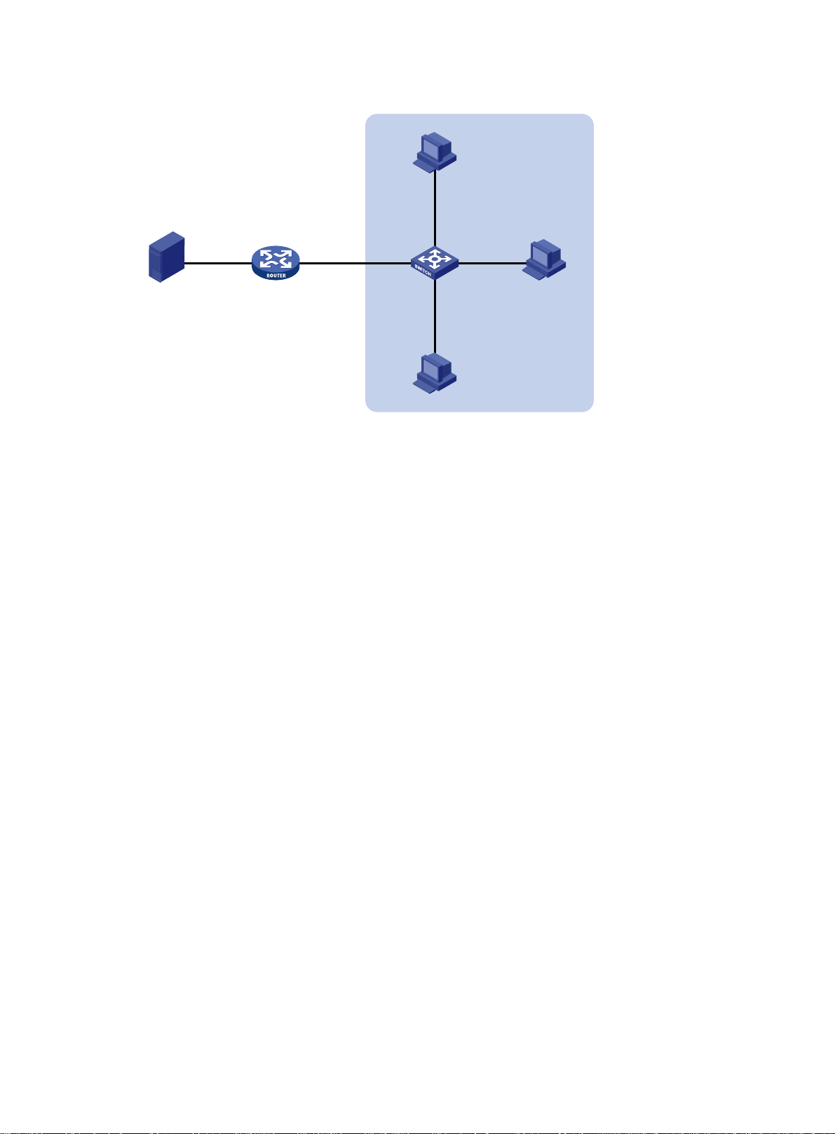
Figure 12 Network diagram
Receiver
Host A
Source
GE1/0/2
1.1.1.2/24
1.1.1.1/24
IGMP querier
Configuration procedure
1. Assign an IP address and subnet mask to each interface according to Figure 12. (Details not
shown.)
2. Configure Router A:
# Enable IP multicast routing.
<RouterA> system-view
[RouterA] multicast routing
[RouterA-mrib] quit
# Enable IGMP on GigabitEthernet 1/0/1.
[RouterA] interface gigabitethernet 1/0/1
[RouterA-GigabitEthernet1/0/1] igmp enable
[RouterA-GigabitEthernet1/0/1] quit
# Enable PIM-DM on GigabitEthernet 1/0/2.
[RouterA] interface gigabitethernet 1/0/2
[RouterA-GigabitEthernet1/0/2] pim dm
[RouterA-GigabitEthernet1/0/2] quit
3. Configure Switch A:
# Enable IGMP snooping globally.
<SwitchA> system-view
[SwitchA] igmp-snooping
[SwitchA-igmp-snooping] quit
# Create VLAN 100, and assign GigabitEthernet 1/0/1 through GigabitEthernet 1/0/4 to the
VLAN.
[SwitchA] vlan 100
[SwitchA-vlan100] port gigabitethernet 1/0/1 to gigabitethernet 1/0/4
# Enable IGMP snooping, and enable dropping unknown multicast data for VLAN 100.
[SwitchA-vlan100] igmp-snooping enable
[SwitchA-vlan100] igmp-snooping drop-unknown
[SwitchA-vlan100] quit
Router A
GE1/0/1
10.1.1.1/24
GE1/0/1
Switch A
GE1/0/4
GE1/0/3
GE1/0/2
Receiver
Host B
Host C
VLAN 100
29
Page 35

# Configure a multicast group policy so that the hosts in VLAN 100 can join only multicast group
224.1.1.1.
[SwitchA] acl number 2001
[SwitchA-acl-basic-2001] rule permit source 224.1.1.1 0
[SwitchA-acl-basic-2001] quit
[SwitchA] igmp-snooping
[SwitchA-igmp-snooping] group-policy 2001 vlan 100
[SwitchA-igmp-snooping] quit
# Configure GigabitEthernet 1/0/3 and GigabitEthernet 1/0/4 as simulated member hosts of
multicast group 224.1.1.1.
[SwitchA] interface gigabitethernet 1/0/3
[SwitchA-GigabitEthernet1/0/3] igmp-snooping host-join 224.1.1.1 vlan 100
[SwitchA-GigabitEthernet1/0/3] quit
[SwitchA] interface gigabitethernet 1/0/4
[SwitchA-GigabitEthernet1/0/4] igmp-snooping host-join 224.1.1.1 vlan 100
[SwitchA-GigabitEthernet1/0/4] quit
Verifying the configuration
# Send IGMP reports from Host A and Host B to join multicast groups 224.1.1.1 and 224.2.2.2.
(Details not shown.)
# Display dynamic IGMP snooping group entries in VLAN 100 on Switch A.
[SwitchA] display igmp-snooping group vlan 100
Total 1 entries.
VLAN 100: Total 1 entries.
(0.0.0.0, 224.1.1.1)
Host slots (0 in total):
Host ports (2 in total):
GE1/0/3 (00:03:23)
GE1/0/4 (00:04:10)
The output shows the following information:
• Host A and Host B have joined multicast group 224.1.1.1 through the member ports
GigabitEthernet 1/0/4 and GigabitEthernet 1/0/3 on Switch A, respectively.
• Host A and Host B have failed to join multicast group 224.2.2.2. It means that the multicast
group policy has taken effect.
Static port configuration example
Network requirements
As shown in Figure 13:
• Router A runs IGMPv2 and acts as the IGMP querier. Switch A, Switch B, and Switch C run
IGMPv2 snooping.
• Host A and host C are permanent receivers of multicast group 224.1.1.1.
Configure static ports to meet the following requirements:
• To enhance the reliability of multicast traffic transmission, configure GigabitEthernet 1/0/3 and
GigabitEthernet 1/0/5 on Switch C as static member ports for multicast group 224.1.1.1.
• Suppose the STP runs on the network, and the forwarding path from Switch A to Switch C is
blocked to avoid data loops. Multicast data flows to the receivers attached to Switch C only
30
Page 36
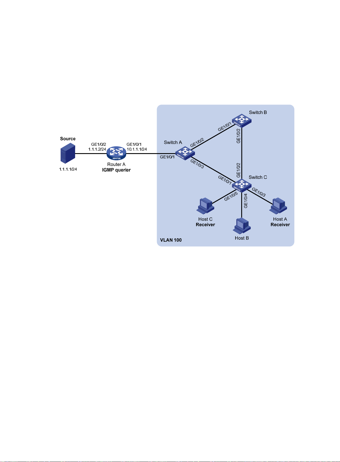
along the path of Switch A—Switch B—Switch C. Wh en this path is blocked, a minimum of one
IGMP query-response cycle must be completed befo r e multicast data flows to the receivers
along the path of Switch A—Switch C. In this case, the multicast delivery is interrupted during
the process. For more information about the STP, see Layer 2—LAN Switching Configuration
Guide.
Configure GigabitEthernet 1/0/3 on Switch A as a static router port. Then, multicast data
uninterruptedly flows to the receivers along the path of Switch A—Switch C when the path of
Switch A—Switch B—Switch C is blocked.
Figure 13 Network diagram
Configuration procedure
1. Assign an IP address and subnet mask to each interface as shown in Figure 13. (Details not
shown.)
2. On Router A:
# Enable IP multicast routing.
<RouterA> system-view
[RouterA] multicast routing
[RouterA-mrib] quit
# Enable IGMP on GigabitEthernet 1/0/1.
[RouterA] interface gigabitethernet 1/0/1
[RouterA-GigabitEthernet1/0/1] igmp enable
[RouterA-GigabitEthernet1/0/1] quit
# Enable PIM-DM on GigabitEthernet 1/0/2.
[RouterA] interface gigabitethernet 1/0/2
[RouterA-GigabitEthernet1/0/2] pim dm
[RouterA-GigabitEthernet1/0/2] quit
3. Configure Switch A:
# Enable IGMP snooping globally.
<SwitchA> system-view
[SwitchA] igmp-snooping
31
Page 37

[SwitchA-igmp-snooping] quit
# Create VLAN 100, and assign GigabitEthernet 1/0/1 through GigabitEthernet 1/0/3 to the
VLAN.
[SwitchA] vlan 100
[SwitchA-vlan100] port gigabitethernet 1/0/1 to gigabitethernet 1/0/3
# Enable IGMP snooping for VLAN 100.
[SwitchA-vlan100] igmp-snooping enable
[SwitchA-vlan100] quit
# Configure GigabitEthernet 1/0/3 as a static router port.
[SwitchA] interface gigabitethernet 1/0/3
[SwitchA-GigabitEthernet1/0/3] igmp-snooping static-router-port vlan 100
[SwitchA-GigabitEthernet1/0/3] quit
4. Configure Switch B:
# Enable IGMP snooping globally.
<SwitchB> system-view
[SwitchB] igmp-snooping
[SwitchB-igmp-snooping] quit
# Create VLAN 100, and assign GigabitEthernet 1/0/1 and GigabitEthernet 1/0/2 to the VLAN.
[SwitchB] vlan 100
[SwitchB-vlan100] port gigabitethernet 1/0/1 gigabitethernet 1/0/2
# Enable IGMP snooping for VLAN 100.
[SwitchB-vlan100] igmp-snooping enable
[SwitchB-vlan100] quit
5. Configure Switch C:
# Enable IGMP snooping globally.
<SwitchC> system-view
[SwitchC] igmp-snooping
[SwitchC-igmp-snooping] quit
# Create VLAN 100, and assign GigabitEthernet 1/0/1 through GigabitEthernet 1/0/5 to the
VLAN.
[SwitchC] vlan 100
[SwitchC-vlan100] port gigabitethernet 1/0/1 to gigabitethernet 1/0/5
# Enable IGMP snooping for VLAN 100.
[SwitchC-vlan100] igmp-snooping enable
[SwitchC-vlan100] quit
# Configure GigabitEthernet 1/0/3 and GigabitEthernet 1/0/5 as static member ports for
multicast group 224.1.1.1.
[SwitchC] interface gigabitethernet 1/0/3
[SwitchC-GigabitEthernet1/0/3] igmp-snooping static-group 224.1.1.1 vlan 100
[SwitchC-GigabitEthernet1/0/3] quit
[SwitchC] interface gigabitethernet 1/0/5
[SwitchC-GigabitEthernet1/0/5] igmp-snooping static-group 224.1.1.1 vlan 100
[SwitchC-GigabitEthernet1/0/5] quit
Verifying the configuration
# Display static router port information for VLAN 100 on Switch A.
[SwitchA] display igmp-snooping static-router-port vlan 100
VLAN 100:
32
Page 38

Router slots (0 in total):
Router ports (1 in total):
1
GE1/0/3
The output shows that GigabitEthernet 1/0/3 on Switch A has become a static router port.
# Display static IGMP snooping group entries in VLAN 100 on Switch C.
[SwitchC] display igmp-snooping static-group vlan 100
Total 1 entries.
VLAN 100: Total 1 entries.
(0.0.0.0, 224.1.1.1)
Host slots (0 in total):
Host ports (2 in total):
GE1/0/3
GE1/0/5
The output shows that GigabitEthernet 1/0/3 and GigabitEthernet 1/0/5 on Switch C have become
static member ports of multicast group 224.1.1.1.
IGMP snooping querier configuration example
Network requirements
As shown in Figure 14:
• The network is a Layer 2-only network.
• Source 1 and Source 2 send multicast data to multicast groups 224.1.1.1 and 225.1.1.1,
respectively.
• Host A and Host C are receivers of multicast group 224.1.1.1, and Host B and Host D are
receivers of multicast group 225.1.1.1.
• All receiver hosts run IGMPv2, and all switches run IGMPv2 snoo ping. Switch A (which is close
to the multicast sources) acts as the IGMP snooping querier.
Configure the switches to meet the following requirements:
• To prevent the switches from flooding unknown packets in the VLAN, enable all the switches to
drop unknown multicast packets.
• To ensure the establishment of Layer 2 forwarding entries, configure the source IP address of
IGMP queries as a non-zero IP address.
33
Page 39

Figure 14 Network diagram
VLAN 100
Receiver Receiver
GE1/0/1
Host A Host B
Receiver
Host D
Configuration procedure
1. Configure Switch A:
# Enable IGMP snooping globally.
<SwitchA> system-view
[SwitchA] igmp-snooping
[SwitchA-igmp-snooping] quit
# Create VLAN 100, and assign GigabitEthernet 1/0/1 through GigabitEthernet 1/0/3 to the
VLAN.
[SwitchA] vlan 100
[SwitchA-vlan100] port gigabitethernet 1/0/1 to gigabitethernet 1/0/3
# Enable IGMP snooping, and enable dropping unknown multicast packets for VLAN 100.
[SwitchA-vlan100] igmp-snooping enable
[SwitchA-vlan100] igmp-snooping drop-unknown
# Enable the IGMP snooping querier in VLAN 100.
[SwitchA-vlan100] igmp-snooping querier
[SwitchA-vlan100] quit
# Configure the source IP address of IGMP general queries and IGMP group-specific queries
as 192.168.1.1 in VLAN 100.
[SwitchA-vlan100] igmp-snooping general-query source-ip 192.168.1.1
[SwitchA-vlan100] igmp-snooping special-query source-ip 192.168.1.1
[SwitchA-vlan100] quit
2. Configure Switch B:
# Enable IGMP snooping globally.
<SwitchB> system-view
[SwitchB] igmp-snooping
[SwitchB-igmp-snooping] quit
# Create VLAN 100, and assign GigabitEthernet 1/0/1 through GigabitEthernet 1/0/4 to the
VLAN.
[SwitchB] vlan 100
[SwitchB-vlan100] port gigabitethernet 1/0/1 to gigabitethernet 1/0/4
Source 1
192.168.1.10/24
GE1/0/2
Switch A
Querier
Switch D
Source 2
192.168.1.20/24
GE1/0/2
GE1/0/3 GE1/0/3 GE1/0/1
Switch B
GE1/0/2GE1/0/1
GE1/0/4
GE1/0/2
GE1/0/1GE1/0/3
Switch C
Receiver
Host C
34
Page 40

# Enable IGMP snooping, and enable dropping unknown multicast packets for VLAN 100.
[SwitchB-vlan100] igmp-snooping enable
[SwitchB-vlan100] igmp-snooping drop-unknown
[SwitchB-vlan100] quit
3. Configure Switch C:
# Enable IGMP snooping globally.
<SwitchC> system-view
[SwitchC] igmp-snooping
[SwitchC-igmp-snooping] quit
# Create VLAN 100, and assign GigabitEthernet 1/0/1 through GigabitEthernet 1/0/3 to the
VLAN.
[SwitchC] vlan 100
[SwitchC-vlan100] port gigabitethernet 1/0/1 to gigabitethernet 1/0/3
# Enable IGMP snooping, and enable dropping unknown multicast packets for VLAN 100.
[SwitchC-vlan100] igmp-snooping enable
[SwitchC-vlan100] igmp-snooping drop-unknown
[SwitchC-vlan100] quit
4. Configure Switch D:
# Enable IGMP snooping globally.
<SwitchD> system-view
[SwitchD] igmp-snooping
[SwitchD-igmp-snooping] quit
# Create VLAN 100, and assign GigabitEthernet 1/0/1 and GigabitEthernet 1/0/2 to the VLAN.
[SwitchD] vlan 100
[SwitchD-vlan100] port gigabitethernet 1/0/1 to gigabitethernet 1/0/2
# Enable IGMP snooping, and enable dropping unknown multicast packets for VLAN 100.
[SwitchD-vlan100] igmp-snooping enable
[SwitchD-vlan100] igmp-snooping drop-unknown
[SwitchD-vlan100] quit
Verifying the configuration
# Display statistics for IGMP messages learned through IGMP snooping on Switch B.
[SwitchB] display igmp-snooping statistics
Received IGMP general queries: 3
Received IGMPv1 reports: 0
Received IGMPv2 reports: 12
Received IGMP leaves: 0
Received IGMPv2 specific queries: 0
Sent IGMPv2 specific queries: 0
Received IGMPv3 reports: 0
Received IGMPv3 reports with right and wrong records: 0
Received IGMPv3 specific queries: 0
Received IGMPv3 specific sg queries: 0
Sent IGMPv3 specific queries: 0
Sent IGMPv3 specific sg queries: 0
Received error IGMP messages: 0
The output shows that all switches except Switch A can receive the IGMP general queries after
Switch A acts as the IGMP snooping querier.
35
Page 41

Troubleshooting IGMP snooping
Layer 2 multicast forwarding cannot function
Symptom
Layer 2 multicast forwarding cannot function on the switch.
Solution
To resolve the problem:
1. Use the display igmp-snooping command to display IGMP snooping status.
2. If IGMP snooping is not enabled, use the igmp-snooping command in system view to enable
IGMP snooping globally, and then use the igmp-snooping enable command in VLAN view to
enable IGMP snooping for the VLAN.
3. If IGMP snooping is enabled globally but not enabled for the VLAN, use the igmp-snooping
enable command in VLAN view to enable IGMP snooping for the VLAN.
4. If the problem persists, contact Hewlett Packard Enterprise Support.
Multicast group policy does not work
Symptom
Hosts can receive multicast data from multicast groups that are not permitted by the multicast group
policy.
Solution
To resolve the problem:
1. Use the display acl command to verify that the configured ACL meets the multicast group
2. Use the display this command in IGMP-snooping view o r in an interface view t o verify that the
3. Use the display igmp-snooping command to verify that the feature of dropping unknown
4. If the problem persists, contact Hewlett Packard Enterprise Support.
policy requirements.
correct multicast group policy has been applied. If not, use the group-policy or
igmp-snooping group-policy command to apply the correct multicast group policy.
multicast data is enabled. If not, use the igmp-snooping drop-unknown command to enable
the feature of dropping unknown multicast data.
36
Page 42

Configuring PIM snooping
Overview
PIM snooping runs on Layer 2 devices. It works with IGMP snooping to analyze received PIM
messages, and adds the ports that are interested in specific multicast data to a PIM snooping routing
entry . In this way , the multicast data can be forwarded to only the ports that are int erested in the data.
Figure 15 Multicast packet transmission without or with PIM snooping
Source 1
PIM
router 1
PIM
router 3
Multicast packet transmission
when only IGMP snooping runs
Source 2
Layer 2 switch
PIM
router 2
PIM
router 4
Multicast packet transmission when
IGMP snooping and PIM snooping both run
Source 1 Source 2
PIM
router 1
Layer 2 switch
PIM
router 3
PIM
router 2
PIM
router 4
Receiver 1 Receiver 2
Multicast packets (S1, G1) Join message (S1, G1)
Multicast packets (S2, G2) Join message (S2, G2)
Receiver 1 Receiver 2
As shown in Figure 15, Source 1 sends multicast data to multicast group G1, and Source 2 sends
multicast data to multicast group G2. Receiver 1 belongs to G1, and Receiver 2 belongs to G2. The
Layer 2 switch's interfaces that connect to the PIM routers are in the same VLAN.
• When the Layer 2 switch runs only IGMP snooping, it performs the following actions:
a. Maintains the router ports according to the received PIM hello messages that PIM routers
send.
b. Broadcasts all other types of received PIM messages except PIM hello messages in the
VLAN.
c. Forwards all multicast data to all router ports in the VLAN.
37
Page 43

Each PIM router in the VLAN, whether interested in the multicast data or not, can receive all
multicast data and all PIM messages except PIM hello messages.
• When the Layer 2 switch runs both IGMP snooping and PIM snoopi ng, it performs the following
actions:
a. Examines whether a PIM router is interested in the multicast data addressed to a multicast
group according to the received PIM messages that the router sends.
b. Adds only the ports that connect to the router and are interested in the data to a PIM
snooping routing entry.
c. Forwards PIM messages and multicast data to only the routers that are interested in the
data, which saves network bandwidth.
For more information about IGMP snooping and the router port, see "Configuring IGMP snooping."
PIM snoo
ping can run in PIM-SM and PIM-SSM networks. Do not configure PIM snooping in
PIM-DM or BIDIR-PIM networks.
Configuring PIM snooping
To configure PIM snooping for a VLAN, enable IGMP snooping globally on the Layer 2 device and
enable IGMP snooping and PIM snooping for the VLAN.
After you enable PIM snooping for a VLAN, PIM snooping works only on the member interfaces of
the VLAN.
To configure PIM snooping:
Step Command Remarks
1. Enter system view.
2. Enable IGMP snooping
globally and enter
IGMP-snooping view.
3. Return to system view.
4. Enter VLAN view.
5. Enable IGMP snooping for
the VLAN.
6. Enable PIM snooping for the
VLAN.
7. (Optional.) Set the aging
time for the PIM snooping
global neighbor ports on the
new master device in IRF
master election.
8. (Optional.) Set the aging
time for the PIM snooping
global downstream ports
and global router ports on
the new master device in
IRF master election.
system-view
igmp-snooping
quit
vlan
igmp-snooping enable
pim-snooping enable
pim-snooping
graceful-restart
neighbor-aging-time
pim-snooping
graceful-restart
join-aging-time
vlan-id
interval
interval
N/A
By default, IGMP snooping is
disabled.
N/A
N/A
By default, IGMP snooping is
disabled in a VLAN.
By default, PIM snooping is disabled
in a VLAN.
The default setting is 105 seconds.
A global neighbor port is a Layer 2
aggregate interface that acts as a
neighbor port.
The default setting is 210 seconds.
A global downstream port or a global
router port is a Layer 2 aggregate
interface that acts as a downstream
port or router port.
Displaying and maintaining PIM snooping
Execute display commands in any view and reset commands in user view.
38
Page 44

Task Command
Display PIM snooping neighbor information.
display pim-snooping neighbor
slot
[
slot-number ] [
verbose ]
[
vlan
vlan-id ]
Display PIM snooping routing entries.
Display PIM snooping router port information .
Display statistics for the PIM messages learned
through PIM snooping.
Clear statistics for the PIM messages learned
through PIM snooping.
display pim-snooping routing-table
slot
[
slot-number ] [
display pim-snooping router-port
slot
[
slot-number ]
display pim-snooping statistics
reset pim-snooping statistics
verbose
PIM snooping configuration example
Network requirements
As shown in Figure 16:
• RIP runs on the network.
• Source 1 sends multicast data to multicast group 224.1.1.1, and Source 2 sends multicast data
to multicast group 225.1.1.1.
• Receiver 1 belongs to multicast group 224.1.1.1, and Receiver 2 belongs to multicast group
225.1.1.1.
• Router C and Router D run IGMP on GigabitEthernet 1/0/1. Route r A, Router B, Router C, and
Router D run PIM-SM.
• GigabitEthernet 1/0/2 on Router A acts as a C-BSR and a C-RP.
vlan
[
vlan-id ]
]
vlan
[
vlan-id ]
Configure IGMP snooping and PIM snooping on Switch A so that Switch A forwards PIM messages
and multicast data to only the routers that are interested in the multicast data.
Figure 16 Network diagram
Configuration procedure
1. Assign an IP address and subnet mask to each interface according to Figure 16. (Details not
shown.)
2. Configure RIP on all the routers. (Details not shown.)
39
Page 45

3. Configure Router A:
# Enable IP multicast routing.
<RouterA> system-view
[RouterA] multicast routing
[RouterA-mrib] quit
# Enable PIM-SM on each interface.
[RouterA] interface gigabitethernet 1/0/1
[RouterA-GigabitEthernet1/0/1] pim sm
[RouterA-GigabitEthernet1/0/1] quit
[RouterA] interface gigabitethernet 1/0/2
[RouterA-GigabitEthernet1/0/2] pim sm
[RouterA-GigabitEthernet1/0/2] quit
# Configure GigabitEthernet 1/0/2 as a C-BSR and a C-RP.
[RouterA] pim
[RouterA-pim] c-bsr 10.1.1.1
[RouterA-pim] c-rp 10.1.1.1
[RouterA-pim] quit
4. Configure Router B:
# Enable IP multicast routing.
<RouterB> system-view
[RouterB] multicast routing
[RouterB-mrib] quit
# Enable PIM-SM on each interface.
[RouterB] interface gigabitethernet 1/0/1
[RouterB-GigabitEthernet1/0/1] pim sm
[RouterB-GigabitEthernet1/0/1] quit
[RouterB] interface gigabitethernet 1/0/2
[RouterB-GigabitEthernet1/0/2] pim sm
[RouterB-GigabitEthernet1/0/2] quit
5. Configure Router C:
# Enable IP multicast routing.
<RouterC> system-view
[RouterC] multicast routing
[RouterC-mrib] quit
# Enable IGMP on GigabitEthernet 1/0/1.
[RouterC] interface gigabitethernet 1/0/1
[RouterC-GigabitEthernet1/0/1] igmp enable
[RouterC-GigabitEthernet1/0/1] quit
# Enable PIM-SM on GigabitEthernet 1/0/2.
[RouterC] interface gigabitethernet 1/0/2
[RouterC-GigabitEthernet1/0/2] pim sm
[RouterC-GigabitEthernet1/0/2] quit
6. Configure Router D:
# Enable IP multicast routing.
<RouterD> system-view
[RouterD] multicast routing
[RouterD-mrib] quit
40
Page 46

# Enable IGMP on GigabitEthernet 1/0/1.
[RouterD] interface gigabitethernet 1/0/1
[RouterD-GigabitEthernet1/0/1] igmp enable
[RouterD-GigabitEthernet1/0/1] quit
# Enable PIM-SM on GigabitEthernet 1/0/2.
[RouterD] interface gigabitethernet 1/0/2
[RouterD-GigabitEthernet1/0/2] pim sm
[RouterD-GigabitEthernet1/0/2] quit
7. Configure Switch A:
# Enable IGMP snooping globally.
<SwitchA> system-view
[SwitchA] igmp-snooping
[SwitchA-igmp-snooping] quit
# Create VLAN 100, assign GigabitEthernet 1/0/1 through GigabitEthernet 1/0/4 to this VLAN,
and enable IGMP snooping and PIM snooping for this VLAN.
[SwitchA] vlan 100
[SwitchA-vlan100] port gigabitethernet 1/0/1 to gigabitethernet 1/0/4
[SwitchA-vlan100] igmp-snooping enable
[SwitchA-vlan100] pim-snooping enable
[SwitchA-vlan100] quit
Verifying the configuration
# On Switch A, display information about PIM snooping neighbors for VLAN 100.
[SwitchA] display pim-snooping neighbor vlan 100
Total 4 neighbors.
VLAN 100: Total 4 neighbors.
10.1.1.1
Slots (0 in total):
Ports (1 in total):
GE1/0/1 (00:32:43)
10.1.1.2
Slots (0 in total):
Ports (1 in total):
GE1/0/2 (00:32:43)
10.1.1.3
Slots (0 in total):
Ports (1 in total):
GE1/0/3 (00:32:43)
10.1.1.4
Slots (0 in total):
Ports (1 in total):
GE1/0/4 (00:32:43)
The output shows that Router A, Router B, Router C, and Router D are PIM snooping neighbors.
# On Switch A, display information about PIM snoopi ng routing entries for VLAN 100.
[SwitchA] display pim-snooping routing-table vlan 100
Total 2 entries.
FSM Flag: NI-no info, J-join, PP-prune pending
41
Page 47

VLAN 100: Total 2 entries.
(*, 224.1.1.1)
Upstream neighbor: 10.1.1.1
Upstream Slots (0 in total):
Upstream Ports (1 in total):
GE1/0/1
Downstream Slots (0 in total):
Downstream Ports (1 in total):
GE1/0/3
Expires: 00:03:01, FSM: J
(*, 225.1.1.1)
Upstream neighbor: 10.1.1.2
Upstream Slots (0 in total):
Upstream Ports (1 in total):
GE1/0/2
Downstream Slots (0 in total):
Downstream Ports (1 in total):
GE1/0/4
Expires: 00:03:11, FSM: J
The output shows the following:
• Switch A will forward the multicast data intended for multicast group 224.1.1.1 to only Router C.
• Switch A will forward the multicast data intended for multicast group 225.1.1.1 to only Router D.
Troubleshooting PIM snooping
PIM snooping does not work on a Layer 2 device
Symptom
PIM snooping does not work on a Layer 2 device.
Solution
1. Use the display current-configuration command to display information about IGMP snooping
and PIM snooping.
2. If IGMP snooping is not enabled, enable IGMP snooping globally, and then enable IGMP
snooping and PIM snooping for the VLAN.
3. If PIM snooping is not enabled, enable PIM snooping for the VLAN.
4. If the problem persists, contact Hewlett Packard Enterprise Support.
42
Page 48

Configuring multicast VLANs
Overview
As shown in Figure 17, Host A, Host B, and Host C are in different VLANs and the same multicast
group. When Switch A (Layer 3 device) receives multicast data for that group, it sends three copies
of the multicast data to Switch B (Layer 2 device). This occupies a large amount of bandwidth and
increases the burden on the Layer 3 device.
Figure 17 Multicast transmission without the multicast VLAN feature
Multicast packets
VLAN 2
VLAN 3
VLAN 4
Source
Switch A
IGMP querier
After a multicast VLAN is configured on Switch B, Switch A sends only one copy of the multica st data
to the multicast VLAN on Switch B. This method saves network bandwidth and lessens the burden
on the Layer 3 device.
Multicast VLANs include sub-VLAN-based multicast VLANs and port-based multicast VLANs.
Sub-VLAN-based multicast VLAN
As shown in Figure 18:
• Host A, Host B, and Host C are in VLAN 2 through VLAN 4, respectively.
• On Switch B, VLAN 10 is a multicast VLAN. VLAN 2 through VLAN 4 are sub-VLANs of VLAN
10.
• IGMP snooping is enabled for the multicast VLAN and its sub-VLANs.
VLAN 2
Receiver
Host A
VLAN 3
Receiver
Host B
Switch B
VLAN 4
Receiver
Host C
43
Page 49
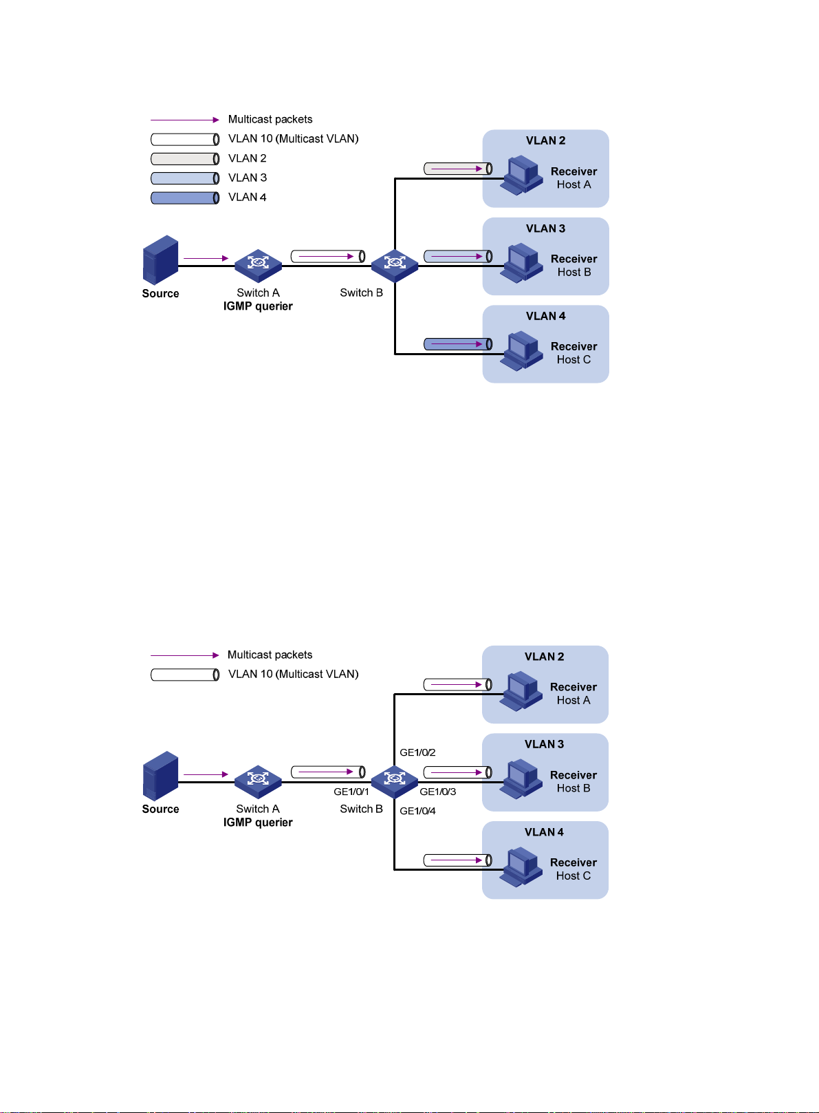
Figure 18 Sub-VLAN-based multicast VLAN
IGMP snooping manages router ports in the multicast VLAN and member ports in each sub-VLAN.
When Switch A receives multicast data from the multicast source, it sends only one copy of the
multicast data to the multicast VLAN on Switch B. Then, Switch B sends a separate copy to each
sub-VLAN of the multicast VLAN.
Port-based multicast VLAN
As shown in Figure 19:
• Host A, Host B, and Host C are in VLAN 2 through VLAN 4, respectively.
• On Switch B, VLAN 10 is a multicast VLAN.
• All the user ports (ports with attached hosts) are hybrid ports and assigned to VLAN 10.
• IGMP snooping is enabled for the multicast VLAN and VLAN 2 through VLAN 4.
Figure 19 Port-based multicast VLAN
IGMP snooping manages the router ports and membe r port s in the multicast VLAN. When Swit ch B
receives an IGMP message from a user port, it tags the message with the multicast VLAN ID and
sends it to the IGMP querier. When Switch A receives multicast data from the multicast source, it
sends only one copy of the multicast data to the multicast VLAN on Switch B. Then, Switch B sends
a separate copy to each user port in the multicast VLAN.
44
Page 50

Multicast VLAN configuration task list
Task at a glance
(Required.) Perform one of the following tasks:
• Configuring a sub-VLAN-based multicast VLAN
• Configuring a port-based multicast VLAN
{ Configuring user port attributes
{ Assigning user ports to a multicast VLAN
(Optional.) Setting the maximum number of multicast VLAN forwarding entries
If you have configured both a sub-VLAN-based multicast VLAN and a port-based multicast VLAN on
a device, the port-based multicast VLAN configuration takes effect.
Configuring a sub-VLAN-based multicast VLAN
To configure a sub-VLAN-based multicast VLAN, you must configure a VLAN as a multicast VLAN,
and assign the VLANs that contain multicast receivers to the multicast VLAN as sub-VLANs.
Configuration prerequisites
Before you configure a sub-VLAN-based multicast VLAN, complete the following tasks:
• Create VLANs as required.
• Enable IGMP snooping for the VLAN to be configured as the multicast VLAN, and for the
VLANs to be configured as sub-VLANs.
Configuration guidelines
When you configure a sub-VLAN-based multicast VLAN, follow these guidelines:
• The VLAN to be configured as the multicast VLAN must exist.
• The VLANs to be configured as sub-VLANs of the multicast VLAN must exist and cannot be
multicast VLANs or sub-VLANs of any other multicast VLAN.
• The total number of multicast VLANs on a device cannot exceed the upper limit.
Configuration procedure
To configure a sub-VLAN-based multicast VLAN:
Step Command Remarks
1. Enter system view.
2. Configure a VLAN as a
multicast VLAN and
enter its view.
3. Assign the specified
VLANs to the multicast
VLAN as sub-VLANs.
system-view
multicast-vla
subvlan
N/A
n vlan-id By default, a VLAN is not a multicast VLAN.
vlan-list
By default, a multicast VLAN does not have
any sub-VLANs.
45
Page 51

Configuring a port-based multicast VLAN
To configure a port-based multicast VLAN, perform the following steps:
1. Configure a VLAN as the multicast VLAN.
2. Configure the attributes for user ports that are connected to the multicast receivers.
3. Assign the user ports to the multicast VLAN.
You can assign a port to a multicast VLAN only when the port is an Ethernet port or a Layer 2
aggregate interface.
Configuration prerequisites
Before you configure a port-based multicast VLAN, complete the following tasks:
• Create VLANs as required.
• Enable IGMP snooping for the VLAN to be configured as the multicast VLAN.
• Enable IGMP snooping for all the VLANs that contain the multicast receivers.
Configuring user port attributes
Step Command Remarks
1. Enter system view.
2. Enter interface view.
3. Configure the link
type of the user port
as hybrid.
4. Specify the PVID of
the current user port
as the VLAN to
which the user port
belongs.
5. Configure the
current user port to
permit the multicast
VLAN and to untag
the packets.
system-view
interface
port link-type hybrid
port hybrid pvid vlan
port hybrid vlan
interface-type interface-number N/A
vlan-id-list
vlan-id
untagged
Assigning user ports to a multicast VLAN
Y ou can either assi gn the user ports to the multicast VLAN in multicast VLAN view , or assign t he user
ports to the multicast VLAN in interface view.
N/A
The default setting is
For more information about this
command, see Layer 2—LAN
Switching Command Reference.
By default, the PVID for a hybrid
port is VLAN 1.
For more information about this
command, see Layer 2—LAN
Switching Command Reference.
By default, a hybrid port permits
only VLAN 1.
For more information about this
command, see Layer 2—LAN
Switching Command Reference.
access
.
When you perform this task, follow these guidelines:
• The VLAN to be configured as a multicast VLAN must exist.
• A port can bel ong to only one multicast VLAN.
46
Page 52

Assigning ports to a multicast VLAN in multicast VLAN view
Step Command Remarks
1. Enter system view.
2. Configure a VLAN as a
multicast VLAN and enter
multicast VLAN view.
3. Assign ports to the
multicast VLAN.
system-view
multicast-vlan
port
interface-list
N/A
vlan-id By default, a VLAN is not a multicast VLAN.
By default, a multicast VLAN does not have
any user ports.
Assigning a port to a multicast VLAN in interface view
Step Command Remarks
1. Enter system view.
2. Configure a VLAN as a
multicast VLAN and
enter its view.
3. Return to system view.
system-view
multicast-vlan
quit
vlan-id
N/A
By default, a VLAN is not a multicast
VLAN.
N/A
4. Enter interface view.
5. Assign the current port
to the multicast VLAN.
interface
interface-number
port multicast-vlan
interface-type
vlan-id
N/A
By default, a user port does not belong
to any multicast VLAN.
Setting the maximum number of multicast VLAN forwarding entries
You can set the maximum number of multicast VLAN forwarding entries on the switch. When the
upper limit is reached, the switch does not create multicast VLAN forwarding entries until some
entries age out or are manually removed.
If the total number of the entries exceeds the upper limit value that you are setting, the system does
not automatically remove existing entries or create new entries. As a best practice, manually remove
some entries to allow new entries to be created.
To set the maximum number of multicast VLAN forwarding entries:
Step Command Remarks
1. Enter system view.
2. Set the maximum number of
multicast VLAN forwarding
entries.
system-view
multicast-vlan entry-limit
N/A
limit The default setting is 256.
Displaying and maintaining multicast VLANs
Execute display commands in any view and reset commands in user view.
Task Command
Display information about multicast
VLANs.
display multicast-vlan
47
[ vlan-id ]
Page 53
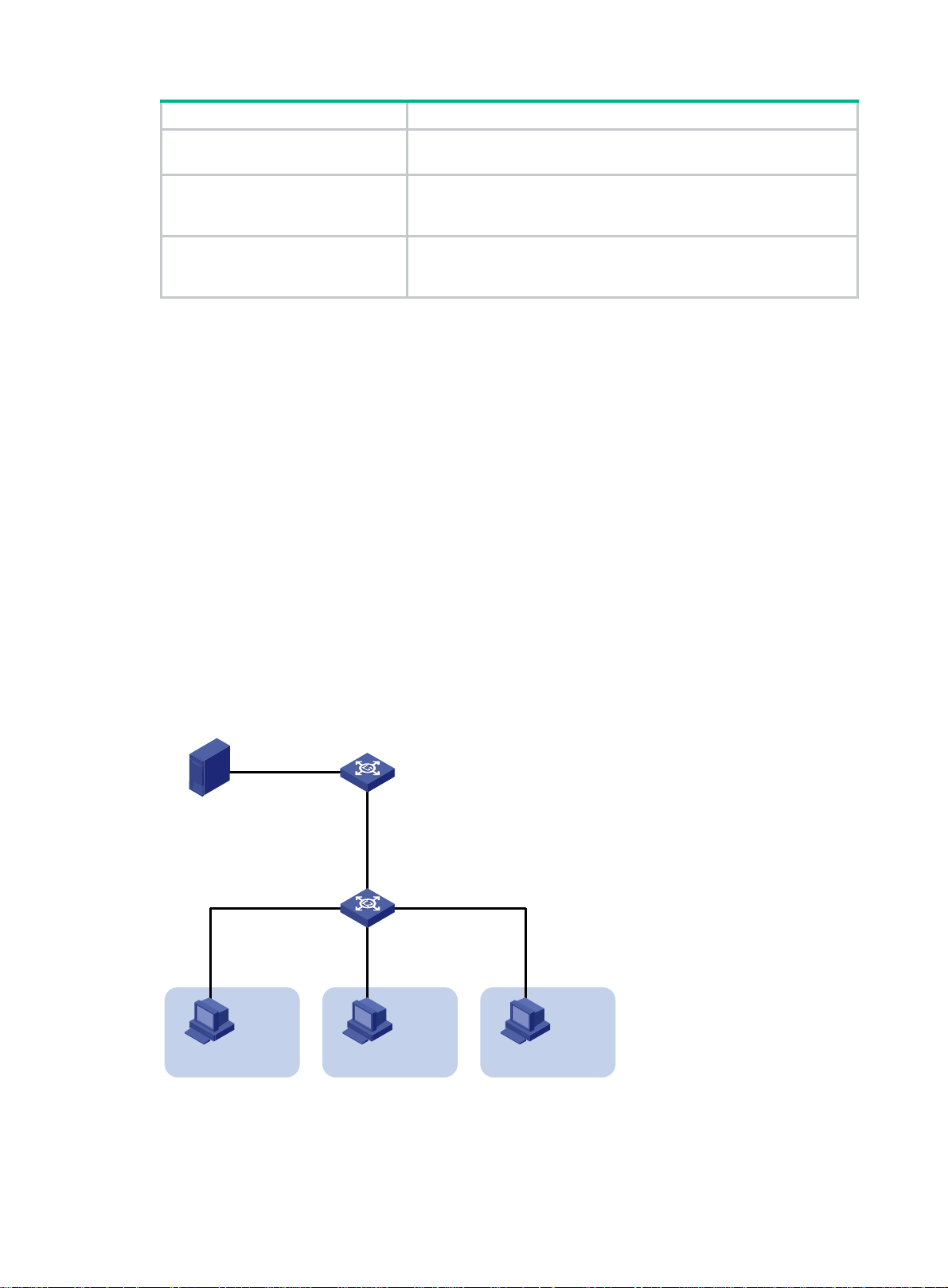
Task Command
Display information about multicast
groups in multicast VLANs.
display multicast-vlan group
slot
slot-number |
verbose
|
[ source-address | group-address |
vlan
vlan-id ] *
Display information about multicast
VLAN forwarding entries.
Clear multicast groups in multicast
VLANs.
display multicast-vlan forwarding-table
{ mask-length | mask } ] | source-address [
mask } ] |
slot
slot-number |
reset multicast-vlan group
mask } ] | group-address [
vlan-id ] *
subvlan
vlan-id |
[ source-address [
mask
{ mask-length | mask } ] |
[ group-address [
mask
{ mask-length |
vlan
vlan-id ] *
mask
mask
{ mask-length |
vlan
Multicast VLAN configuration examples
Sub-VLAN-based multicast VLAN configuration example
Network requirements
As shown in Figure 20:
• IGMPv2 runs on Layer 3 device Switch A, and IGMPv2 snooping runs on Layer 2 device Switch
B.
• Switch A acts as the IGMP querier.
• The multicast source sends multicast data to multicast group 224.1.1.1. Host A, Host B, and
Host C are receivers. They belong to VLAN 2 through VLAN 4, respectively.
Configure a sub-VLAN-based multicast VLAN on Switch B to meet the following requirements:
• Switch A sends the multicast data to Switch B through the multicast VLAN.
• Switch B forwards the multicast data to the receivers in different user VLANs.
Figure 20 Network diagram
Source
1.1.1.1/24
Receiver
Host A
VLAN 2
Configuration procedure
1. Configure Switch A:
# Enable IP multicast routing.
GE1/0/2
Vlan-int20
1.1.1.2/24
Switch B
GE1/0/2
IGMP querier
Switch A
GE1/0/1
Vlan-int10
10.110.1.1/24
GE1/0/1
GE1/0/4
GE1/0/3
Receiver
Host B
VLAN 3
Receiver
VLAN 4
Host C
48
Page 54

<SwitchA> system-view
[SwitchA] multicast routing
[SwitchA-mrib] quit
# Create VLAN 20, and assign GigabitEthernet 1/0/2 to this VLAN.
[SwitchA] vlan 20
[SwitchA-vlan20] port gigabitethernet 1/0/2
[SwitchA-vlan20] quit
# Assign an IP address to VLAN-interface 20, and enable PIM-DM on this interface.
[SwitchA] interface vlan-interface 20
[SwitchA-Vlan-interface20] ip address 1.1.1.2 24
[SwitchA-Vlan-interface20] pim dm
[SwitchA-Vlan-interface20] quit
# Create VLAN 10.
[SwitchA] vlan 10
[SwitchA-vlan10] quit
# Configure GigabitEthernet 1/0/1 as a hybrid port, and assign it to VLAN 10 as a tagged VLAN
member.
[SwitchA] interface gigabitethernet 1/0/1
[SwitchA-GigabitEthernet1/0/1] port link-type hybrid
[SwitchA-GigabitEthernet1/0/1] port hybrid vlan 10 tagged
[SwitchA-GigabitEthernet1/0/1] quit
# Assign an IP address to VLAN-interface 10, and enable IGMP on this interface.
[SwitchA] interface vlan-interface 10
[SwitchA-Vlan-interface10] ip address 10.110.1.1 24
[SwitchA-Vlan-interface10] igmp enable
[SwitchA-Vlan-interface10] quit
2. Configure Switch B:
# Enable IGMP snooping.
<SwitchB> system-view
[SwitchB] igmp-snooping
[SwitchB-igmp-snooping] quit
# Create VLAN 2, assign GigabitEthernet 1/0/2 to this VLAN, and enable IGMP snooping in thi s
VLAN.
[SwitchB] vlan 2
[SwitchB-vlan2] port gigabitethernet 1/0/2
[SwitchB-vlan2] igmp-snooping enable
[SwitchB-vlan2] quit
# Create VLAN 3, assign GigabitEthernet 1/0/3 to this VLAN, and enable IGMP snooping in thi s
VLAN.
[SwitchB] vlan 3
[SwitchB-vlan3] port gigabitethernet 1/0/3
[SwitchB-vlan3] igmp-snooping enable
[SwitchB-vlan3] quit
# Create VLAN 4, assign GigabitEthernet1/0/4 to this VLAN, and enable IGMP snooping in this
VLAN.
[SwitchB] vlan 4
[SwitchB-vlan4] port gigabitethernet 1/0/4
[SwitchB-vlan4] igmp-snooping enable
49
Page 55

[SwitchB-vlan4] quit
# Create VLAN 10, and enable IGMP snooping for this VLAN.
[SwitchB] vlan 10
[SwitchB-vlan10] igmp-snooping enable
[SwitchB-vlan10] quit
# Configure GigabitEthernet 1/0/1 as a hybrid port, and assign it to VLAN 10 as a tagged VLAN
member.
[SwitchB] interface gigabitethernet 1/0/1
[SwitchB-GigabitEthernet1/0/1] port link-type hybrid
[SwitchB-GigabitEthernet1/0/1] port hybrid vlan 10 tagged
[SwitchB-GigabitEthernet1/0/1] quit
# Configure VLAN 10 as a multicast VLAN, and configure VLAN 2 through VLAN 4 as
sub-VLANs.
[SwitchB] multicast-vlan 10
[SwitchB-mvlan-10] subvlan 2 to 4
[SwitchB-mvlan-10] quit
Verifying the configuration
# Display information about all multicast VLANs on Switch B.
[SwitchB] display multicast-vlan
Total 1 multicast VLANs.
Multicast VLAN 10:
Sub-VLAN list(3 in total):
2-4
Port list(0 in total):
# Display information about multicast groups in multicast VLANs on Switch B.
[SwitchB] display multicast-vlan group
Total 1 entries.
Multicast VLAN 10: Total 1 entries.
(0.0.0.0, 224.1.1.1)
Sub-VLANs (3 in total):
VLAN 2
VLAN 3
VLAN 4
The output shows that multicast group 224.1.1.1 belongs to multicast VLAN 10. Multicast VLAN 10
contains sub-VLANs VLAN 2 through VLAN 4. Switch B will replicate the multicast data of VLAN 10
to VLAN 2 through VLAN 4.
Port-based multicast VLAN configuration example
Network requirements
As shown in Figure 21:
• IGMPv2 runs on Switch A. IGMPv2 snooping runs on Switch B.
• Switch A acts as the IGMP querier.
• The multicast source sends multicast data to multicast group 224.1.1.1. Host A, Host B, and
Host C are receivers. They belong to VLAN 2 through VLAN 4, respectively.
50
Page 56
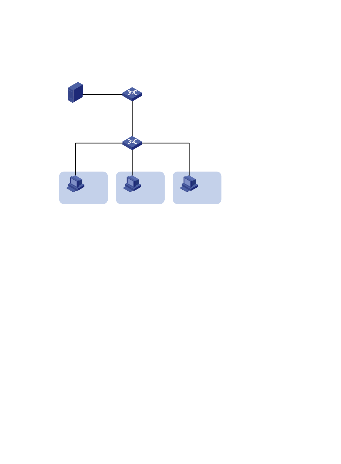
Configure a port-based multicast VLAN on Switch B to meet the following requirements:
• Switch A sends multicast data to Switch B through the multicast VLAN.
• Switch B forwards the multicast data to the receivers in different user VLANs.
Figure 21 Network diagram
Source
1.1.1.1/24
Receiver
Host A
VLAN 2
Configuration procedure
1. Configure Switch A:
# Enable IP multicast routing.
<SwitchA> system-view
[SwitchA] multicast routing
[SwitchA-mrib] quit
# Create VLAN 20, and assign GigabitEthernet 1/0/2 to this VLAN.
[SwitchA] vlan 20
[SwitchA-vlan20] port gigabitethernet 1/0/2
[SwitchA-vlan20] quit
# Assign an IP address to VLAN-interface 20, and enable PIM-DM on this interface.
[SwitchA] interface vlan-interface 20
[SwitchA-Vlan-interface20] ip address 1.1.1.2 24
[SwitchA-Vlan-interface20] pim dm
[SwitchA-Vlan-interface20] quit
# Create VLAN 10, and assign GigabitEthernet 1/0/1 to the VLAN.
[SwitchA] vlan 10
[SwitchA-vlan10] port gigabitethernet 1/0/1
[SwitchA-vlan10] quit
# Assign an IP address to VLAN-interface 10, and enable IGMP on this interface.
[SwitchA] interface vlan-interface 10
[SwitchA-Vlan-interface10] ip address 10.110.1.1 24
[SwitchA-Vlan-interface10] igmp enable
[SwitchA-Vlan-interface10] quit
2. Configure Switch B:
# Enable IGMP snooping globally.
GE1/0/2
Vlan-int20
1.1.1.2/24
Switch B
GE1/0/2
IGMP querier
Switch A
GE1/0/1
Vlan-int10
10.110.1.1/24
GE1/0/1
GE1/0/4
GE1/0/3
Receiver
Host B
VLAN 3
Receiver
VLAN 4
Host C
51
Page 57

<SwitchB> system-view
[SwitchB] igmp-snooping
[SwitchB-igmp-snooping] quit
# Create VLAN 10, assign GigabitEthernet 1/0/1 to VLAN 10, and enable IGMP snooping for
this VLAN.
[SwitchB] vlan 10
[SwitchB-vlan10] port gigabitethernet 1/0/1
[SwitchB-vlan10] igmp-snooping enable
[SwitchB-vlan10] quit
# Create VLAN 2, and enable IGMP snooping for the VLAN.
[SwitchB] vlan 2
[SwitchB-vlan2] igmp-snooping enable
[SwitchB-vlan2] quit
# Create VLAN 3, and enable IGMP snooping for the VLAN.
[SwitchB] vlan 3
[SwitchB-vlan3] igmp-snooping enable
[SwitchB-vlan3] quit
# Create VLAN 4, and enable IGMP snooping for the VLAN.
[SwitchB] vlan 4
[SwitchB-vlan4] igmp-snooping enable
[SwitchB-vlan4] quit
# Configure GigabitEthernet 1/0/2 as a hybrid port, and configure VLAN 2 as the PVID of the
hybrid port.
[SwitchB] interface gigabitethernet 1/0/2
[SwitchB-GigabitEthernet1/0/2] port link-type hybrid
[SwitchB-GigabitEthernet1/0/2] port hybrid pvid vlan 2
# Assign GigabitEthernet 1/0/2 to VLAN 2 and VLAN 10 as an untagged VLAN member.
[SwitchB-GigabitEthernet1/0/2] port hybrid vlan 2 untagged
[SwitchB-GigabitEthernet1/0/2] port hybrid vlan 10 untagged
[SwitchB-GigabitEthernet1/0/2] quit
# Configure GigabitEthernet 1/0/3 as a hybrid port, and configure VLAN 3 as the PVID of the
hybrid port.
[SwitchB] interface gigabitethernet 1/0/3
[SwitchB-GigabitEthernet1/0/3] port link-type hybrid
[SwitchB-GigabitEthernet1/0/3] port hybrid pvid vlan 3
# Assign GigabitEthernet 1/0/3 to VLAN 3 and VLAN 10 as an untagged VLAN member.
[SwitchB-GigabitEthernet1/0/3] port hybrid vlan 3 untagged
[SwitchB-GigabitEthernet1/0/3] port hybrid vlan 10 untagged
[SwitchB-GigabitEthernet1/0/3] quit
# Configure GigabitEthernet 1/0/4 as a hybrid port, and configure VLAN 4 as the PVID of the
hybrid port.
[SwitchB] interface gigabitethernet 1/0/4
[SwitchB-GigabitEthernet1/0/4] port link-type hybrid
[SwitchB-GigabitEthernet1/0/4] port hybrid pvid vlan 4
# Assign GigabitEthernet 1/0/4 to VLAN 4 and VLAN 10 as an untagged VLAN member.
[SwitchB-GigabitEthernet1/0/4] port hybrid vlan 4 untagged
[SwitchB-GigabitEthernet1/0/4] port hybrid vlan 10 untagged
[SwitchB-GigabitEthernet1/0/4] quit
52
Page 58

# Configure VLAN 10 as a multicast VLAN.
[SwitchB] multicast-vlan 10
# Assign GigabitEthernet 1/0/2 and GigabitEthernet 1/0/3 to VLAN 10.
[SwitchB-mvlan-10] port gigabitethernet 1/0/2 to gigabitethernet 1/0/3
[SwitchB-mvlan-10] quit
# Assign GigabitEthernet 1/0/4 to VLAN 10.
[SwitchB] interface gigabitethernet 1/0/4
[SwitchB-GigabitEthernet1/0/4] port multicast-vlan 10
[SwitchB-GigabitEthernet1/0/4] quit
Verifying the configuration
# Display information about multicast VLANs on Switch B.
[SwitchB] display multicast-vlan
Total 1 multicast VLANs.
Multicast VLAN 10:
Sub-VLAN list(0 in total):
Port list(0 in total):
GE1/0/2
GE1/0/3
GE1/0/4
# Display information about IGMP snooping group entries for dynamic multicast group s on Switch B.
[SwitchB] display igmp-snooping group
Total 1 entries.
VLAN 2: Total 1 entries.
(0.0.0.0, 224.1.1.1)
Host slots (0 in total):
Host ports (3 in total):
GE1/0/2 (00:03:23)
GE1/0/3 (00:04:07)
GE1/0/4 (00:04:16)
The output shows that IGMP snooping maintains the user ports in VLAN 10. Switch B will forward the
multicast data of VLAN 10 through these user ports.
53
Page 59

Configuring MLD snooping
Overview
MLD snooping runs on a Layer 2 device as an IPv6 multicast constraining mechanism to improve
multicast forwarding efficiency. It creates Layer 2 multicast forwarding entries from MLD messages
that are exchanged between the hosts and the router.
As shown in Figure 22,
packets to all hosts. When MLD snooping is enabled, the Layer 2 d evice forwards multica st packets
of known IPv6 multicast groups to only the receivers.
Figure 22 Multicast packet transmission processes without and with MLD snooping
when MLD snooping is not enabled, the Layer 2 device floods IPv6 mu lticast
Basic MLD snooping concepts
MLD snooping related ports
As shown in Figure 23, MLD snooping runs on Switch A and Switch B, and Host A and Host C are
receiver hosts in an IPv6 multicast group.
54
Page 60

Figure 23 MLD snooping related ports
Router A Switch A
GE1/0/1 GE1/0/2
GE1/0/3
GE1/0/1
Source
Switch B
Router port
Member port
IPv6 multicast packets
Receiver
GE1/0/2
Host C
Host D
Receiver
Host A
Host B
The following describes the ports involved in MLD snooping, as shown in Figure 23:
• Router port—Layer 3 multicast device-side port. Layer 3 multicast devices include designated
routers and MLD queriers. In Figure 23, GigabitEthernet 1/0/1 of Switch
A and G igabitEthernet
1/0/1 of Switch B are the router ports. A Layer 2 device records all its local router ports in a
router port list.
Do not confuse the "router port" in MLD snooping with the "routed interface" commonly known
as the "Layer 3 interface." The router port in MLD snooping is a Layer 2 interface.
• Member port—Multicast receiver-side port. In Figure 23, GigabitEthern
et 1/0/2 and
GigabitEthernet 1/0/3 of Switch A and GigabitEthernet 1/0/2 of Switch B are member ports. A
Layer 2 device records all its local member ports in its MLD snooping forwarding table.
Unless otherwise specified, router ports and member ports in this document in clude both stat ic
and dynamic router ports and member ports.
NOTE:
When MLD snooping is enabled, all ports that receive IPv6 PIM hello messages or MLD general
queries with a source IP address other than 0::0 are considered dynamic router ports.
Aging timers for dynamic ports in MLD snooping
The following are aging timers for dynamic ports in MLD snooping:
• Dynamic router port aging timer—The Layer 2 device starts this timer for a port that receives
an MLD general query with the source address other than 0::0 or an I Pv6 PIM hello message. If
the port does not receive either of these messages before the timer expires, the Layer 2 devi ce
removes the port from its router port list.
• Dynamic member port aging timer—The Layer 2 device starts this timer for a port that
receives an MLD report. If the port does not receive a report before the timer exp ires, the Layer
2 device removes the port from the MLD snooping forwarding entries.
NOTE:
In MLD snooping, only dynamic ports age out. Static ports never age out.
55
Page 61

How MLD snooping works
The ports in this section are dynamic ports. For information about how to configure and remove static
ports, see "Configuring static ports."
MLD me
Layer 2 device performs differently depending on the MLD message.
General query
The MLD querier periodically sends MLD general queries to all hosts and routers on the local subnet
to check for the existence of IPv6 multicast group members.
After receiving an MLD general query, the Layer 2 device forwards the query to all ports in the VLAN
except the receiving port. The Layer 2 device also performs one of the following actions:
• If the receiving port is a dynamic router port in the router port list, the Layer 2 device restarts the
aging timer for the router port.
• If the receiving port does not exist in the router port list, the Layer 2 device adds the port to the
router port list. It also starts an aging timer for the port.
MLD report
A host sends an MLD report to the MLD querier for the following purposes:
• Responds to queries if the host is an IPv6 multicast group member.
• Applies for an IPv6 multicast group membership.
After receiving an MLD report from a host, the Layer 2 device forwards the report through all the
router ports in the VLAN. It also resolves the IPv6 address of the reported IPv6 multicast group, and
looks up the forwarding table for a matching entry:
• If no match is found, the Layer 2 device creates a forwarding entry for the group and adds the
receiving port as an outgoing interface to the forwarding entry. It also marks the receiving port
as a dynamic member port and starts an aging timer for the port.
• If a match is found but the receiving port is not in the forwarding entry, the Layer 2 device adds
the receiving port as an outgoing interface to the forwarding entry. It also marks the receiving
port as a dynamic member port and starts an aging timer for the port.
• If a match is found and the receiving port is in the forwarding entry, the Layer 2 device restarts
the aging timer for the port.
ssages include general query, MLD report, and done message. An MLD snooping-enabled
In an application with an IPv6 multicast group policy configured on an MLD snooping-enabled Layer
2 device, when a user requests a multicast program, the user's host initiates an MLD report. After
receiving this report message, the Layer 2 device resolves the IPv6 multicast group address in the
report and performs ACL filtering on the report. If the report passes ACL filteri ng, the Layer 2 device
creates an MLD snooping forwarding entry for the IPv6 multica st group with the receivin g port as an
outgoing interface. If the report does not pass ACL filtering, the Layer 2 device drops this report
message, which means the receiver does not successfully join the IPv6 multicast group and cannot
retrieve the program.
A Layer 2 device does not forward an MLD report through a non-router port because of the MLD
report suppression mechanism.
Done message
When a host leaves an IPv6 multicast group, the host sends an MLD done message to the multicast
routers. When the Layer 2 device receives the MLD done message on a dynamic member port, the
Layer 2 device first examines whether a forwarding entry matches the IPv6 multicast group address
in the message.
• If no match is found, the Layer 2 device discards the MLD done message.
• If a match is found but the receiving port is not in the forwarding entry, the Layer 2 device
discards the MLD done message.
56
Page 62

• If a match is found and the receiving port is in the forwarding entry, the Layer 2 device forwards
the done message to all router ports in the VLAN. The Layer 2 device does not immediately
remove the port from the forwarding entry for that group. Instead, it restarts the aging timer for
the port.
After receiving the MLD done message, the MLD querier resolves the IPv6 multicast group address
in the message. Then, it sends an MLD multicast-address-specific query to the IPv6 multicast group
through the port that received the done message.
After receiving the MLD multicast-address-specific query, the Layer 2 device forwards the query
through all its router ports in the VLAN and all member ports of the IPv6 multicast group. Then, it
waits for the responding MLD reports from the directly connected hosts. For the dynamic member
port that received the done message, the Layer 2 device also performs on e of the following acti ons:
• If the port receives an MLD report before the aging timer expires, the Layer 2 device adjusts the
aging timer for the port.
• If the port does not receive any MLD report when the aging timer expires, the Layer 2 device
removes the port from the forwarding entry for the IPv6 multicast group.
Protocols and standards
RFC 4541, Considerations for Internet Group Management Protocol (IGMP) and Multicast Listener
Discovery (MLD) Snooping Switches
MLD snooping configuration task list
Tasks at a glance
Configuring basic MLD snooping features:
• (Required.) Enabling MLD snooping
• (Optional.) Specifying an MLD snooping version
• (Optiona
Configuring MLD snooping port features:
• (Optional.) Setting aging timers for dynamic ports
• (Optional.) Configuring static ports
• (Optional.) Configuring a port as a simulated member host
• (Optional.) Enabling fast-leave processing
• (Optiona
Configuring the MLD snooping querier:
• (Optional.) Enabling the MLD snooping querier
• (Optiona
Configuring parameters for MLD messages:
• (Optional.) Configuring source IPv6 addresses for MLD messages
• (Optiona
l.) Setting the maximum number of MLD snooping forwarding entries
l.) Disabling a port from becoming a dynamic router port
l.) Configuring parameters for MLD queries and responses
l.) Setting the 802.1p priority for MLD messages
Configuring MLD snooping policies:
• (Optional.) Configuring an IPv6 multicast group policy
• (Optiona
• (Optional.) Enabling dropping unknown IPv6 multicast data
• (Optional.) Enabling MLD report suppression
• (Optional.) Setting the maximum number of IPv6 multicast groups on a port
• (Optional.) Enabling IPv6 multicast group replacement
l.) Configuring IPv6 multicast source port filtering
57
Page 63

The MLD snooping configurations made on Layer 2 aggregate interfaces do not interfere with the
configurations made on member ports. In addition, the configurations made on Layer 2 aggregate
interfaces do not take part in aggregation calculations. The configuration made on a member port of
the aggregate group takes effect after the port leaves the aggregate group.
Configuring basic MLD snooping features
Before you configure basic MLD snooping features, complete the following tasks:
• Configure the associated VLANs.
• Determine the MLD snooping version.
• Determine the MLD last listener query interval.
• Determine the maximum response time for MLD general queries.
Enabling MLD snooping
When you enable MLD snooping, follow these guidelines:
• You must enable MLD snooping globally before you can enable it for a VLAN.
• MLD snooping for a VLAN works only on the member ports in that VLAN.
• You can enable MLD snooping for the specified VLANs in MLD-snooping view or for a VLAN in
VLAN view. For a VLAN, the configuration in VLAN interface has the same priority as the
configuration in MLD-snooping view, and the most recent configuration takes effect.
To enable MLD snooping for a VLAN in MLD-snooping view:
Step Command Remarks
1. Enter system view.
2. Enable MLD snooping
globally and enter
MLD-snooping view.
3. Enable MLD snooping for the
specified VLANs.
To enable MLD snooping for a VLAN in VLAN view:
system-view
mld-snooping
enable vlan
vlan-list
N/A
By default, MLD snooping is
globally disabled.
By default, MLD snooping is
disabled for a VLAN.
Step Command Remarks
1. Enter system view.
2. Enable MLD snooping
globally and enter
MLD-snooping view.
3. Return to system view.
4. Enter VLAN view.
5. Enable MLD snooping for the
VLAN.
system-view
mld-snooping
quit
vlan
vlan-id
mld-snooping enable
N/A
By default, MLD snooping is
globally disabled.
N/A
N/A
By default, MLD snooping is
disabled in a VLAN.
Specifying an MLD snooping version
Different MLD snooping versions can process different versions of MLD messages:
58
Page 64

• MLDv1 snooping can process MLDv1 messages, but it floods MLDv2 messages in the VLAN
instead of processing them.
• MLDv2 snooping can process MLDv1 and MLDv2 messages.
If you change MLDv2 snooping to MLDv1 snooping, the system does the following:
• Clears all MLD snooping forwarding entries that are dynamically created.
• Keeps static MLDv2 snooping forwarding entries (*, G).
• Clears static MLDv2 snooping forwarding entries (S, G), which will be restore d when MLD
snooping is switched back to MLDv2 snooping.
For more information about static MLD snooping forwarding entries, see "Configuring static ports."
You can specify the version for the specified VLANs in MLD-snooping view or for a VLAN in VLAN
view. For a VLAN, the configuration in VLAN view has the same priority as the configuration in
MLD-snooping view, and the most recent configuration takes effect.
Specifying an MLD snooping version in MLD-snooping view
Step Command Remarks
1. Enter system view.
2. Enable MLD snooping
globally and enter
MLD-snooping view.
3. Specify an MLD snooping
version for the specified
VLANs.
system-view
mld-snooping
version
vlan-list
N/A
version-number
vlan
Specifying an MLD snooping version in VLAN view
Step Command Remarks
1. Enter system view.
2. Enter VLAN view.
3. Specify an MLD snooping
version for the VLAN.
system-view
vlan
vlan-id
mld-snooping version
version-number
N/A
The default setting is 1.
N/A
N/A
The default setting in a VLAN is 1.
Setting the maximum number of MLD snooping forwarding entries
You can modify the maximum number of MLD snooping forwarding entries, including dynamic
entries and static entries. When the number of forwarding entries on the switch reaches the upper
limit, the switch does not automatically remove any existing entries. As a best practice, manually
remove some entries to allow new entries to be created.
To set the maximum number of MLD snooping forwarding entries:
Step Command Remarks
1. Enter system view.
2. Enter MLD-snooping view.
3. Set the maximum number of
MLD snooping forwarding
entries.
system-view
mld-snooping
entry-limit
N/A
limit
59
N/A
The default setting is
4294967295.
Page 65

Configuring MLD snooping port features
Before you configure MLD snooping port features, complete the following tasks:
• Enable MLD snooping for the VLAN.
• Determine the aging timer for dynamic router ports.
• Determine the aging timer for dynamic member ports.
• Determine the addresses of the IPv6 multicast group and IPv6 multicast source.
Setting aging timers for dynamic ports
When you set aging timers for dynamic ports, follow these guidelines:
• If the memberships of IPv6 multicast groups frequently change, set a relatively small value for
the aging timer of the dynamic member ports. If the memberships of IPv6 multicast groups
rarely change, you can set a relatively large value.
• If a dynamic router port receives an IPv6 PIMv2 hello message, the aging timer value for the
port is specified by the hello message. In this case, the mld-snooping router-aging-time
command does not take effect on the port.
• Y ou can set the timers globally for all VLANs in MLD-snoopi ng view or for a VLAN in VLAN view .
For a VLAN, the VLAN-specific configuration takes priority over the global configuration.
Setting the aging timers for dynamic ports globally
Step Command Remarks
1. Enter system view.
2. Enter MLD-snooping view.
3. Set the aging timer for
dynamic router ports
globally.
4. Set the aging timer for
dynamic member ports
globally.
system-view
mld-snooping
router-aging-time
host-aging-time
N/A
interval
interval
Setting the aging timers for the dynamic ports in a VLAN
Step Command Remarks
1. Enter system view.
2. Enter VLAN view.
3. Set the aging timer for
the dynamic router ports
in the VLAN.
4. Set the aging timer for
the dynamic member
ports in the VLAN.
system-view
vlan
vlan-id
mld-snooping router-aging-time
interval
mld-snooping host-aging-time
interval
N/A
N/A
The default setting is 260
seconds.
The default setting is 260
seconds.
N/A
The default setting is 260 seconds.
The default setting is 260 seconds.
Configuring static ports
You can configure the following types of static ports:
• Static member port—When you configure a port as a static member port for an IPv6 multicast
group, all hosts attached to the port will receive IPv6 multicast data for the group.
60
Page 66

The static member port does not respond to MLD queries. When you complete or cancel this
configuration, the port does not send an unsolicited report or done message.
• Static router port—When you configure a port as a static router port for an IPv6 multicast
group, all IPv6 multicast data for the group received on the port will be forwarded.
Static member ports and static router ports never age out. To remove such a port, use the undo
mld-snooping static-group or undo mld-snooping static-router-port command.
To configure static ports:
Step Command Remarks
1. Enter system view.
2. Enter Layer 2 Ethernet
interface view or Layer 2
aggregate interface view.
3. Configure the port as a static
port.
system-view
interface
interface-number
• Configure the port as a static
member port:
mld-snooping static-group
ipv6-group-address
[ source-ip
ipv6-source-address ] vlan
vlan-id
• Configure the port as a static
router port:
mld-snooping
static-router-port vlan
vlan-id
N/A
interface-type
N/A
By default, a port is not a static
member port or a static router
port.
Configuring a port as a simulated member host
When a port is configured as a simulated member host, it is equivalent to an independent host in the
following ways:
• It sends an unsolicited MLD report when you complete the configuration.
• It responds to MLD general queries with MLD reports.
• It sends an MLD done message when you remove the configuration.
The version of MLD running on the simulated member host is the same as the version of MLD
snooping running on the port. The port ages out in the same ways as a dynamic member port.
To configure a port as a simulated member host:
Step Command Remarks
1. Enter system view.
2. Enter Layer 2 Ethernet
interface view or Layer 2
aggregate interface view.
3. Configure the port as a
simulated member host.
system-view
interface
interface-number
mld-snooping host-join
ipv6-group-address [
ipv6-source-address ]
interface-type
source-ip
vlan
vlan-id
N/A
N/A
By default, the port is not a
simulated member host.
Enabling fast-leave processing
This feature enables the switch to immediately remove a port from the forwarding entry for an IPv6
multicast group when the port receives a done message.
61
Page 67

Configuration restrictions and guidelines
When you enable fast-leave processing feature, follow these restri ctions and guidelines:
• Do not enable fast-leave processing on a port that have multiple receiver hosts attached in a
VLAN. If fast-leave processing is enabled, after a receiver host leaves an IPv6 multicast group,
the other receivers cannot receive IPv6 multicast data for the group.
• You can enable fast-leave processing for the current port in interface view or globally for all
ports in MLD-snooping view. The configuration made in interface view takes priority over the
configuration made in MLD-snooping view.
Enabling fast-leave processing globally
Step Command Remarks
1. Enter system view.
2. Enter MLD-snooping view.
3. Enable fast-leave processing
globally.
system-view
mld-snooping
fast-leave [ vlan
Enabling fast-leave processing on a port
Step Command Remarks
1. Enter system view.
2. Enter Layer 2 Ethernet
interface view or Layer 2
aggregate interface view.
3. Enable fast-leave processing
on the port.
system-view
interface
interface-number
mld-snooping fast-leave [ vlan
vlan-list ]
N/A
N/A
vlan-list ]
N/A
interface-type
By default, fast-leave processing
is globally disabled.
N/A
By default, fast-leave processing
is disabled on a port.
Disabling a port from becoming a dynamic router port
A receiver host might send MLD general queries or IPv6 PIM hello messages for testing purposes.
On the Layer 2 device, the port that receives either of the messages becomes a dy namic router port.
Before the aging timer for the port expires, the following problems might occur:
• All IPv6 multicast data for the VLAN to which the port belongs flows to the port. Then, the port
forwards the data to attached receiver hosts. The receiver hosts will receive IPv6 multicast data
that it does not expect.
• The port forwards the MLD general queries or IPv6 PIM hello messages to its upstream
multicast routers. These messages might affect the multicast routing protocol state (such as the
MLD querier or DR election) on the multicast routers. This might further cause network
interruption.
To solve these problems, you can disable the router port from becoming a dynamic router port when
receiving either of the messages. This also improves network security and the control over receiver
hosts.
To disable a port from becoming a dynamic router port:
Step Command Remarks
1. Enter system view.
2. Enter Layer 2 Ethernet
interface view or Layer 2
aggregate interface view.
system-view
interface
interface-number
interface-type
N/A
N/A
62
Page 68

Step Command Remarks
3. Disable the port from
becoming a dynamic router
port.
mld-snooping router-port-deny
vlan
[
vlan-list ]
By default, a port can become a
dynamic router port.
This configuration does not affect
the static router port configuration.
Configuring the MLD snooping querier
This section describes how to configure an MLD snooping querier.
Configuration prerequisites
Before you configure an MLD snooping querier for a VLAN, complete the following tasks:
• Enable MLD snooping for the VLAN.
• Determine the MLD general query interval.
• Determine the MLD last listener query interval.
• Determine the maximum response time for MLD general queries.
Enabling the MLD snooping querier
This feature enables the switch to periodically send MLD general queries to establish and maintain
multicast forwarding entries at the data link Layer. You can configure an MLD snooping querier on a
network without Layer 3 multicast devices.
Do not enable the MLD snooping querier on an IPv6 multicast network that runs MLD. An MLD
snooping querier does not participate in MLD querier elections. However, it might affect MLD querier
elections if it sends MLD general queries with a low source IPv6 address.
To enable the MLD snooping querier for a VLAN:
Step Command Remarks
1. Enter system view.
2. Enter VLAN view.
3. Enable the MLD snooping
querier for the VLAN.
system-view
vlan-id
vlan
mld-snooping querier
N/A
N/A
By default, the MLD snooping
querier is disabled for a VLAN.
Configuring parameters for MLD queries and responses
CAUTION:
To avoid mistakenly deleting IPv6 multicast group members, make sure the MLD general query
interval is greater than the maximum response time for MLD general queries.
You can modify the MLD general query interval based on the actual network conditions.
A receiver host starts a tim er for each IPv6 multicast group that it has joined when it receives an MLD
query (general query or multicast-address-specific query). This timer is initialized to a rand om value
in the range of 0 to the maximum response time advertised in the MLD query message. When the
timer value decreases to 0, the host sends an MLD report to the IPv6 multicast group.
63
Page 69

T o speed up t he response of hosts to MLD queries a nd to avoid simultaneous timer expirations which
cause MLD report traffic bursts, you must correctly set the maximum response time.
• The maximum response time for MLD general queries is set by the max-response-time
command.
• The maximum response time for MLD multicast-address-specific queries equals the MLD last
listener query interval, which is set by the last-listener-query-interval command.
• Y ou can configure th e parameters globally for all VLANs in MLD-snoopin g view or for a VLAN in
VLAN view. For a VLAN, the VLAN-specific configuration takes priority over the global
configuration.
Configuring parameters for MLD queries and responses globally
Step Command Remarks
1. Enter system view.
2. Enter MLD-snooping view.
3. Set the maximum response
time for MLD general
queries.
4. Set the MLD last listener
query interval.
system-view
mld-snooping
max-response-time
last-listener-query-interval
interval
N/A
interval
N/A
The default setting is 10 seconds.
The default setting is 1 second.
Configuring parameters for MLD queries and responses in a VLAN
Step Command Remarks
1. Enter system view.
2. Enter VLAN view.
3. Set the MLD general query
interval for the VLAN.
4. Set the maximum response
time for MLD general queries
in the VLAN.
5. Set the MLD last listener
query interval in the VLAN.
system-view
vlan
vlan-id
mld-snooping query-interval
interval
mld-snooping
max-response-time
mld-snooping
last-listener-query-interval
interval
N/A
interval
N/A
The default setting is 125
seconds.
The default setting is 10 seconds.
The default setting is 1 second.
Configuring parameters for MLD messages
This section describes how to configure parameters for MLD messages.
Configuration prerequisites
Before you configure parameters for MLD messages in a VLAN, complete the following tasks:
• Enable MLD snooping for the VLAN.
• Determine the source IPv6 address of MLD general queries.
• Determine the source IPv6 address of MLD multicast-address-specific queries.
• Determine the source IPv6 address of MLD reports.
• Determine the source IPv6 address of MLD done messages.
• Determine the 802.1p priority of MLD messages.
64
Page 70

Configuring source IPv6 addresses for MLD messages
Changing the source IPv6 address of MLD queries might affect MLD querier election within the
subnet.
To configure the source IP address for MLD queries in a VLAN:
Step Command Remarks
1. Enter system view.
2. Enter VLAN view.
3. Configure the source IPv6
address for MLD general
queries.
4. Configure the source IPv6
address for MLD
multicast-address-specific
queries.
system-view
vlan
mld-snooping general-query
source-ip
mld-snooping special-query
source-ip
vlan-id
ipv6-address
ipv6-address
N/A
N/A
The default setting is the IPv6
link-local address of the current
VLAN interface. If the current
VLAN interface does not have an
IPv6 link-local address, the
source IPv6 address is
FE80::02FF:FFFF:FE00:0001.
By default, the source IPv6
address of MLD
multicast-address-specific
queries is one of the following:
• The source address of MLD
general queries if the MLD
snooping querier has
received MLD general
queries.
• The IPv6 link-local address
of the current VLAN interface
if the MLD snooping querier
does not receive an MLD
general query.
• FE80::02FF:FFFF:FE00:000
1 if the MLD snooping
querier does not receive an
MLD general query and the
current VLAN interface does
not have an IPv6 link-local
address.
5. Configure the source IPv6
address for MLD reports.
6. Configure the source IPv6
address for MLD done
messages.
mld-snooping report source-ip
ipv6-address
mld-snooping done source-ip
ipv6-address
65
The default setting is the IPv6
link-local address of the current
VLAN interface. If the current
VLAN interface does not have an
IPv6 link-local address, the
source IPv6 address is
FE80::02FF:FFFF:FE00:0001.
The default setting is the IPv6
link-local address of the current
VLAN interface. If the current
VLAN interface does not have an
IPv6 link-local address, the
source IPv6 address is
FE80::02FF:FFFF:FE00:0001.
Page 71

Setting the 802.1p priority for MLD messages
When congestion occurs on outgoing ports of the Layer 2 device, it forwa rds MLD messages i n their
802.1p priority order, from highest to lowest. You can assign a higher 802.1p priority to MLD
messages that are created or forwarded by the switch.
Y ou can configure the 802. 1p priority of MLD messages for all VLANs in MLD-snooping view or for a
VLAN in VLAN view. For a VLAN, the VLAN-specific configuration takes priority over the global
configuration.
Setting the 802.1p priority for MLD messages globally
Step Command Remarks
1. Enter system view.
2. Enter MLD-snooping view.
3. Set the 802.1p priority for
MLD messages.
Setting the 802.1p priority for MLD messages in a VLAN
Step Command Remarks
1. Enter system view.
2. Enter VLAN view.
3. Set the 802.1p priority for
MLD messages in the
VLAN.
system-view
mld-snooping
dot1p-priority
system-view
vlan
vlan-id
mld-snooping dot1p-priority
priority-number
priority-number The default setting is 0.
N/A
N/A
N/A
N/A
The default setting is 0.
Configuring MLD snooping policies
Before you configure MLD snooping policies, complete the following tasks:
• Enable MLD snooping for the VLAN.
• Determine the ACLs to be used by the IPv6 multicast group policies.
• Determine the maximum number of IPv6 multicast groups that a port can join.
Configuring an IPv6 multicast group policy
This feature enables the switch to filter MLD reports by using an ACL that spe cifies the IPv6 multicast
groups and the optional sources. It is used to control the IPv6 multicast groups that receiver hosts
can join.
When you configure an IPv6 multicast group policy, follow these guidelines:
• This configuration takes effect only on the IPv6 multicast groups that the port joins dyn amically.
• You can configure an IPv6 multicast group policy globally for all ports in MLD-snooping view or
for a port in interface view. For a port, the port-specific configuration takes priority over the
global configuration.
Configuring an IPv6 multicast group policy globally
Step Command Remarks
1. Enter system view.
system-view
N/A
66
Page 72

Step Command Remarks
2. Enter MLD-snooping view.
mld-snooping
N/A
3. Configure an IPv6 multicast
group policy globally.
group-policy
vlan-list ]
acl6-number [
vlan
By default, no IPv6 multicast
group policies exist. Hosts can
join all IPv6 multicast groups.
Configuring an IPv6 multicast group policy on a port
Step Command Remarks
1. Enter system view.
2. Enter Layer 2 Ethernet
interface view or Layer 2
aggregate interface view.
3. Configure an IPv6 multicast
group policy for the port.
system-view
interface
interface-number
mld-snooping group-policy
acl6-number [
N/A
interface-type
vlan
vlan-list ]
N/A
By default, no IPv6 multicast
group policies exist. Hosts can
join all IPv6 multicast groups.
Configuring IPv6 multicast source port filtering
This feature enables the switch to discard all IPv6 multicast data packets and to accept IPv6
multicast protocol packets. You can enable this feature on ports that connect to only IPv6 multicast
receivers.
You can enable multicast source port filtering for the specified ports in MLD-snooping view or for a
port in interface view. For a port, the configuration in interface view has the same priority as the
configuration in MLD-snooping view, and the most recent configuration takes effect.
Enabling IPv6 multicast source port filtering in MLD-snooping view
Step Command Remarks
1. Enter system view.
2. Enter MLD-snooping view.
3. Enable IPv6 multicast source
port filtering.
system-view
mld-snooping
source-deny port
interface-list
N/A
N/A
By default, IPv6 multicast source
port filtering is disabled.
Enabling IPv6 multicast source port filtering in interface view
Step Command Remarks
1. Enter system view.
2. Enter Layer 2 Ethernet
interface view.
3. Enable IPv6 multicast source
port filtering.
system-view
interface
interface-number
mld-snooping source-deny
interface-type
N/A
N/A
By default, the IPv6 multicast
source port filtering is disabled.
Enabling dropping unknown IPv6 multicast data
This feature enables the Layer 2 device to drop all unknown IPv6 multicast data. Unknown IPv6
multicast data refers to IPv6 multicast data for which no forwarding entries exist in the MLD snooping
forwarding table.
67
Page 73

To enable dropping unknown IPv6 multicast data for a VLAN:
Step Command Remarks
1. Enter system view.
2. Enter VLAN view.
system-view
vlan
vlan-id
N/A
N/A
3. Enable dropping unknown
IPv6 multicast data for the
VLAN.
mld-snooping drop-unknown
By default, this feature is disabled.
Unknown IPv6 multicast data is
flooded in the VLAN to which the
data belongs.
Enabling MLD report suppression
This feature enables the switch to forward only the first MLD report for an IPv6 multicast group to its
directly connected Layer 3 device. Other reports for the same group within the same query interval
are discarded. This reduces the multicast traf fic.
To enable MLD report suppression:
Step Command Remarks
1. Enter system view.
2. Enter MLD-snooping view.
3. Enable MLD report
suppression.
system-view
mld-snooping
report-aggregation
N/A
N/A
By default, MLD report
suppression is enabled.
Setting the maximum number of IPv6 multicast groups on a port
You can set the maximum number of IPv6 multicast groups on a port to regulate the port traffic.
Configuration restrictions and guidelines
When you set the maximum number of IPv6 multicast groups on a port, follow these restrictio ns and
guidelines:
• This configuration takes effect only on the IPv6 multicast groups that the port joins dyn amically.
• If the number of IPv6 multicast groups on a port exceeds the limit, the system removes all the
forwarding entries related to that port. In this case, the receiver hosts attached to that port can
join IPv6 multicast groups again before the number of IPv6 multicast groups on the port reaches
the limit.
Configuration procedure
To set the maximum number of IPv6 multicast groups on a port:
Step Command Remarks
1. Enter system view.
2. Enter Layer 2 Ethernet
interface view or Layer 2
aggregate interface view.
3. Set the maximum number of
IPv6 multicast groups on a
port.
system-view
interface
interface-number
mld-snooping group-limit
vlan
[
N/A
interface-type
vlan-list ]
limit
N/A
The default setting is
4294967295.
68
Page 74

Enabling IPv6 multicast group replacement
This feature enables the switch to replace an existing IPv6 multicast group with a newly joined IPv6
multicast group when the number of groups exceeds the upper limit. This feature is typically used in
the channel switching application. Without this feature, the switch discards MLD reports for new
groups, and the user cannot change to the new channel.
Configuration restrictions and guidelines
When you enable the IPv6 multicast group replacement feature, follow these restrictions and
guidelines:
• This configuration takes effect only on the multicast groups that the port joins dynamically.
• You can enable this feature globally for all ports in MLD-snooping view or for a port in interface
view. For a port, the port-specific configuration takes priority over the global configuration.
Enabling IPv6 multicast group replacement globally
Step Command Remarks
1. Enter system view.
2. Enter MLD-snooping view.
3. Enable the IPv6 multicast
group replacement feature
globally.
system-view
mld-snooping
overflow-replace [ vlan
N/A
vlan-list ]
N/A
By default, the IPv6 multicast
group replacement feature is
disabled.
Enabling IPv6 multicast group replacement on a port
Step Command Remarks
1. Enter system view.
2. Enter Layer 2 Ethernet
interface view or Layer 2
aggregate interface view.
3. Enable the IPv6 multicast
group replacement feature
on the port.
system-view
interface
interface-number
mld-snooping overflow-replace
vlan
[
N/A
interface-type
vlan-list ]
N/A
By default, the IPv6 multicast
group replacement feature is
disabled.
Displaying and maintaining MLD snooping
Execute display commands in any view and reset commands in user view.
Task Command
Display information about Layer 2
IPv6 multicast groups.
Display Layer 2 IPv6 multicast group
entries.
display ipv6 l2-multicast ip [ group
source
vlan
vlan-id ] [
ipv6-source-address ] * [
ipv6-source-address ] * [
display ipv6 l2-multicast ip forwarding
ipv6-group-address |
slot
[
slot-number ]
ipv6-group-address |
slot
slot-number ]
group
[
vlan
source
vlan-id ]
Display information about Layer 2
IPv6 MAC multicast groups.
Display Layer 2 IPv6 MAC multicast
group entries.
Display MLD snooping status.
display ipv6 l2-multicast mac
slot
69
slot-number ]
[
slot-number ]
display ipv6 l2-multicast mac forwarding
vlan-id ] [
display mld-snooping
[ mac-address ] [
global
|
vlan
vlan-id ]
vlan
vlan-id ] [
[ mac-address ] [
slot
vlan
Page 75

Task Command
Display dynamic MLD snooping
group entries.
display mld-snooping group
ipv6-source-address ] * [
slot-number ]
[ ipv6-group-address |
vlan
vlan-id ] [
verbose
] [
slot
Display static MLD snooping group
entries.
Display dynamic router port
information.
Display static router port information.
Display statistics for the MLD
messages learned through MLD
snooping.
Delete dynamic MLD snooping group
entries.
Delete dynamic router ports.
Clear statistics for the MLD
messages learned through MLD
snooping.
display mld-snooping static-group
ipv6-source-address ] * [
slot-number ]
display mld-snooping router-port
slot-number ]
display mld-snooping static-router-port
slot-number ]
display mld-snooping statistics
reset mld-snooping group
[ ipv6-source-address ] |
reset mld-snooping router-port
reset mld-snooping statistics
vlan
vlan-id ] [
{ ipv6-group-address
all
} [
[ ipv6-group-address |
verbose
vlan
[
vlan-id ] [
vlan
[
vlan
vlan-id ]
all
{
|
vlan
vlan-id }
slot
] [
vlan-id ] [
MLD snooping configuration examples
IPv6 group policy and simulated joining configuration
slot
slot
example (for VLANs)
Network requirements
As shown in Figure 24, Router A runs MLDv1 and acts as the MLD querier , and Switch A runs MLDv1
snooping.
Configure a group policy to achieve the following goals:
• Host A and Host B receive only the IPv6 multicast data addressed to IPv6 multicast group
FF1E::101. In addition, IPv6 multicast data is uninterruptedly forwarded through
GigabitEthernet 1/0/3 and GigabitEthernet 1/0/4 of Switch A, even thoug h Host A and Host B
temporarily fail.
• Switch A drops unknown IPv6 multicast data instead of flooding it in VLAN 100.
70
Page 76

Figure 24 Network diagram
Configuration procedure
1. Assign an IPv6 address and prefix length to each interface according to Figure 24. (Details not
shown.)
2. Configure Router A:
# Enable IPv6 multicast routing.
<RouterA> system-view
[RouterA] ipv6 multicast routing
[RouterA-mrib6] quit
# Enable MLD on GigabitEthernet 1/0/1.
[RouterA] interface gigabitethernet 1/0/1
[RouterA-GigabitEthernet1/0/1] mld enable
[RouterA-GigabitEthernet1/0/1] quit
# Enable IPv6 PIM-DM on GigabitEthernet 1/0/2.
[RouterA] interface gigabitethernet 1/0/2
[RouterA-GigabitEthernet1/0/2] ipv6 pim dm
[RouterA-GigabitEthernet1/0/2] quit
3. Configure Switch A:
# Enable MLD snooping globally.
<SwitchA> system-view
[SwitchA] mld-snooping
[SwitchA-mld-snooping] quit
# Create VLAN 100, and assign GigabitEthernet 1/0/1 through GigabitEthernet 1/0/4 to the
VLAN.
[SwitchA] vlan 100
[SwitchA-vlan100] port gigabitethernet 1/0/1 to gigabitethernet 1/0/4
# Enable MLD snooping, and enable dropping IPv6 unknown multicast data for VLAN 100.
[SwitchA-vlan100] mld-snooping enable
[SwitchA-vlan100] mld-snooping drop-unknown
[SwitchA-vlan100] quit
71
Page 77

# Configure an IPv6 multicast group policy so that the hosts in VLAN 100 can join only the IPv6
multicast group FF1E::101.
[SwitchA] acl ipv6 number 2001
[SwitchA-acl6-basic-2001] rule permit source ff1e::101 128
[SwitchA-acl6-basic-2001] quit
[SwitchA] mld-snooping
[SwitchA–mld-snooping] group-policy 2001 vlan 100
[SwitchA–mld-snooping] quit
# Configure GigabitEthernet 1/0/3 and GigabitEthernet 1/0/4 as simulated member hosts to join
IPv6 multicast group FF1E::101.
[SwitchA] interface gigabitethernet 1/0/3
[SwitchA-GigabitEthernet1/0/3] mld-snooping host-join ff1e::101 vlan 100
[SwitchA-GigabitEthernet1/0/3] quit
[SwitchA] interface gigabitethernet 1/0/4
[SwitchA-GigabitEthernet1/0/4] mld-snooping host-join ff1e::101 vlan 100
[SwitchA-GigabitEthernet1/0/4] quit
Verifying the configuration
# Send MLD reports from Host A and Host B to join IPv6 multicast groups FF1E::101 and FF1E::202.
(Details not shown.)
# Display dynamic MLD snooping group entries for VLAN 100 on Switch A.
[SwitchA] display mld-snooping group vlan 100
Total 1 entries.
VLAN 100: Total 1 entries.
(::, FF1E::101)
Host slots (0 in total):
Host ports (2 in total):
GE1/0/3 (00:03:23)
GE1/0/4 (00:04:10)
The output shows the following information:
• Host A and Host B have joined IPv6 multicast group FF1E::101 (through the member ports
GigabitEthernet 1/0/4 and GigabitEthernet 1/0/3 on Switch A, re spectively).
• Host A and Host B have failed to join IPv6 multicast group FF1E::202.
Static port configuration example
Network requirements
As shown in Figure 25:
• Router A runs MLDv1 and acts as the MLD querier, and Switch A, Switch B, and Switch C run
MLDv1 snooping.
• Host A and Host C are permanent receivers of IPv6 multicast group FF1E::101.
Configure static ports to meet the following requirements:
• To enhance the reliability of IPv6 multicast traffic transmission, configure GigabitEthernet 1/0/3
and GigabitEthernet 1/0/5 on Switch C as static member ports for IPv6 multicast group
FF1E::101.
• Suppose the STP runs on the network. To avoid data loops, the forwarding path from Switch A
to Switch C is blocked under normal conditions. IPv6 multicast data flows to the receivers
72
Page 78

attached to Switch C only along the path of Switch A—Switch B— Switch C. When this path is
blocked, a minimum of one MLD query-response cycle must be completed before IPv6
multicast data flows to the receivers along the path of Switch A—Switch C. In this case, the
multicast delivery is interrupted during the process. For more information about the STP, see
Layer 2—LAN Switching Configuration Guide.
Configure GigabitEthernet 1/0/3 on Switch A as a static router port. Then, IPv6 multicast data
uninterruptedly flows to the receivers along the path of Switch A—Switch C when the path of
Switch A—Switch B—Switch C is blocked.
Figure 25 Network diagram
Switch B
1
/
0
/
1
E
G
Source
1::1/64
GE1/0/2
1::2/64
Router A
MLD querier
GE1/0/1
2001::1/64
Switch A
GE1/0/1
2
/
0
/
1
E
G
G
E
1
/
0
/
3
G
E
1
/
0
/
1
1
E
G
Switch C
GE
1
/
5
/
0
/
0
/
3
Configuration procedure
1. Assign an IPv6 address and prefix length to each interface according to Figure 25. (Details not
shown.)
2. Configure Router A:
# Enable IPv6 multicast routing.
<RouterA> system-view
[RouterA] ipv6 multicast routing
[RouterA-mrib6] quit
# Enable MLD on GigabitEthernet 1/0/1.
[RouterA] interface gigabitethernet 1/0/1
[RouterA-GigabitEthernet1/0/1] mld enable
[RouterA-GigabitEthernet1/0/1] quit
# Enable IPv6 PIM-DM on GigabitEthernet 1/0/2.
[RouterA] interface gigabitethernet 1/0/2
[RouterA-GigabitEthernet1/0/2] ipv6 pim dm
[RouterA-GigabitEthernet1/0/2] quit
3. Configure Switch A:
# Enable MLD snooping globally.
<SwitchA> system-view
[SwitchA] mld-snooping
VLAN 100
Host C
Receiver
Host A
Receiver
Host B
73
Page 79

[SwitchA-mld-snooping] quit
# Create VLAN 100, and assign GigabitEthernet 1/0/1 through GigabitEthernet 1/0/3 to the
VLAN.
[SwitchA] vlan 100
[SwitchA-vlan100] port gigabitethernet 1/0/1 to gigabitethernet 1/0/3
# Enable MLD snooping for VLAN 100.
[SwitchA-vlan100] mld-snooping enable
[SwitchA-vlan100] quit
# Configure GigabitEthernet 1/0/3 as a static router port.
[SwitchA] interface gigabitethernet 1/0/3
[SwitchA-GigabitEthernet1/0/3] mld-snooping static-router-port vlan 100
[SwitchA-GigabitEthernet1/0/3] quit
4. Configure Switch B:
# Enable MLD snooping globally.
<SwitchB> system-view
[SwitchB] mld-snooping
[SwitchB-mld-snooping] quit
# Create VLAN 100, and assign GigabitEthernet 1/0/1 and GigabitEthernet 1/0/2 to the VLAN.
[SwitchB] vlan 100
[SwitchB-vlan100] port gigabitethernet 1/0/1 gigabitethernet 1/0/2
# Enable MLD snooping for VLAN 100.
[SwitchB-vlan100] mld-snooping enable
[SwitchB-vlan100] quit
5. Configure Switch C:
# Enable MLD snooping globally.
<SwitchC> system-view
[SwitchC] mld-snooping
[SwitchC-mld-snooping] quit
# Create VLAN 100, and assign GigabitEthernet 1/0/1 through GigabitEthernet 1/0/5 to the
VLAN.
[SwitchC] vlan 100
[SwitchC-vlan100] port gigabitethernet 1/0/1 to gigabitethernet 1/0/5
# Enable MLD snooping for VLAN 100.
[SwitchC-vlan100] mld-snooping enable
[SwitchC-vlan100] quit
# Configure GigabitEthernet 1/0/3 and GigabitEthernet 1/0/5 as static member ports for the
IPv6 multicast group FF1E::101.
[SwitchC] interface gigabitethernet 1/0/3
[SwitchC-GigabitEthernet1/0/3] mld-snooping static-group ff1e::101 vlan 100
[SwitchC-GigabitEthernet1/0/3] quit
[SwitchC] interface gigabitethernet 1/0/5
[SwitchC-GigabitEthernet1/0/5] mld-snooping static-group ff1e::101 vlan 100
[SwitchC-GigabitEthernet1/0/5] quit
Verifying the configuration
# Display static router port information for VLAN 100 on Switch A.
[SwitchA] display mld-snooping static-router-port vlan 100
VLAN 100:
74
Page 80

Router slots (1 in total):
1
Router ports (1 in total):
GE1/0/3
The output shows that GigabitEthernet 1/0/3 on Switch A has become a static router port.
# Display static MLD snooping group entries in VLAN 100 on Switch C.
[SwitchC] display mld-snooping static-group vlan 100
Total 1 entries).
VLAN 100: Total 1 entries).
(::, FF1E::101)
Host slots (0 in total):
Host ports (2 in total):
GE1/0/3
GE1/0/5
The output shows that GigabitEthernet 1/0/3 and GigabitEthernet 1/0/5 on Switch C have become
static member ports of IPv6 multicast group FF1E::101.
MLD snooping querier configuration example
Network requirements
As shown in Figure 26:
• The network is a Layer 2-only network.
• Source 1 and Source 2 send multicast data to IPv6 multicast groups FF1E::101 and FF1E::102,
respectively.
• Host A and Host C are receivers of IPv6 multicast group FF1E::101 , and Host B and Host D are
receivers of IPv6 multicast group FF1E::102.
• All receiver hosts run MLDv1 and all switches run MLDv1 snooping. Switch A (which is close to
the multicast sources) acts as the MLD snooping querier.
To prevent the switches from flooding unknown IPv6 packets in the VLAN, enable all the switches to
drop unknown IPv6 multicast packets.
75
Page 81
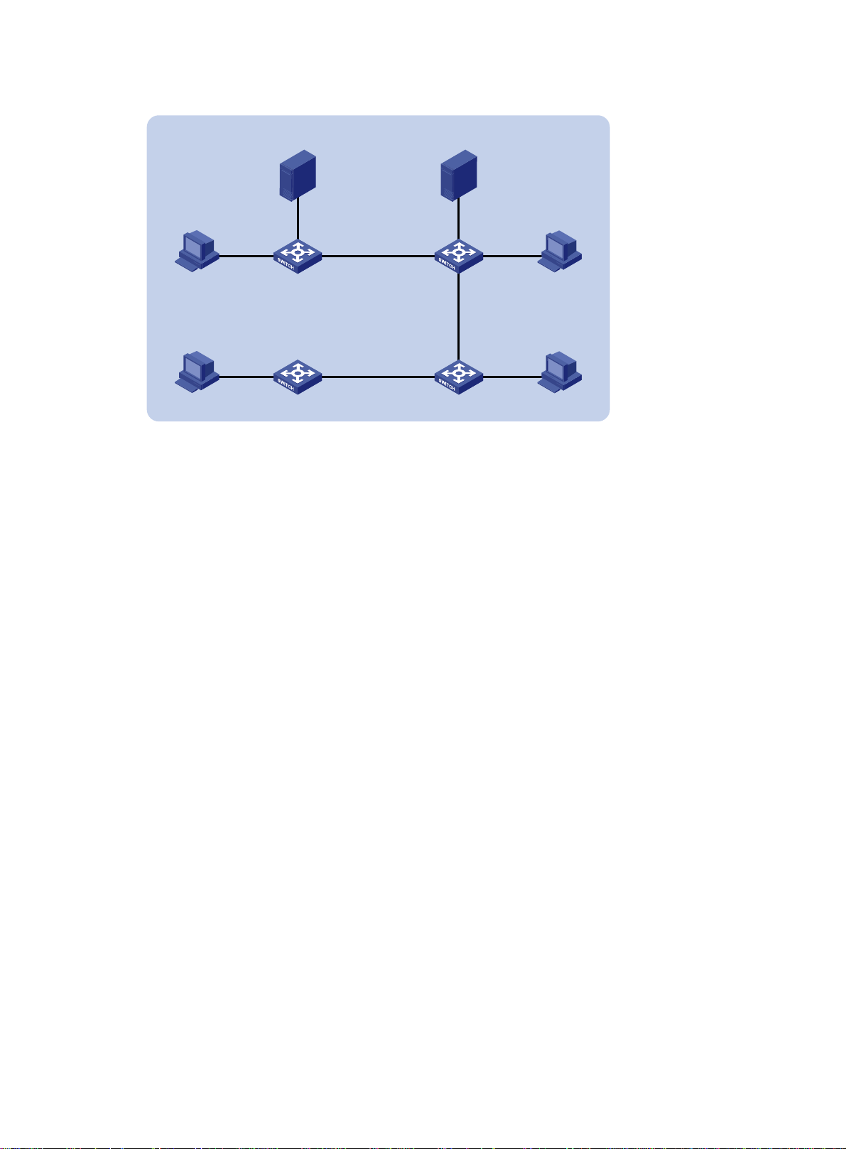
Figure 26 Network diagram
VLAN 100
Receiver Receiver
GE1/0/1
Host A Host B
Receiver
Host D
Configuration procedure
1. Configure Switch A:
# Enable MLD snooping globally.
<SwitchA> system-view
[SwitchA] mld-snooping
[SwitchA-mld-snooping] quit
# Create VLAN 100, and assign GigabitEthernet 1/0/1 through GigabitEthernet 1/0/3 to the
VLAN.
[SwitchA] vlan 100
[SwitchA-vlan100] port gigabitethernet 1/0/1 to gigabitethernet 1/0/3
# Enable MLD snooping, and enable dropping unknown IPv6 multicast packets for VLAN 100.
[SwitchA-vlan100] mld-snooping enable
[SwitchA-vlan100] mld-snooping drop-unknown
# Enable the MLD snooping querier in VLAN 100.
[SwitchA-vlan100] mld-snooping querier
[SwitchA-vlan100] quit
2. Configure Switch B:
# Enable MLD snooping globally.
<SwitchB> system-view
[SwitchB] mld-snooping
[SwitchB-mld-snooping] quit
# Create VLAN 100, and assign GigabitEthernet 1/0/1 through GigabitEthernet 1/0/4 to the
VLAN.
[SwitchB] vlan 100
[SwitchB-vlan100] port gigabitethernet 1/0/1 to gigabitethernet 1/0/4
# Enable MLD snooping, and enable dropping unknown multicast packets for VLAN 100.
[SwitchB-vlan100] mld-snooping enable
[SwitchB-vlan100] mld-snooping drop-unknown
[SwitchB-vlan100] quit
Source 1
1::10/64
GE1/0/2
Switch A
Querier
Switch D
Source 2
1::20/64
GE1/0/2
GE1/0/3 GE1/0/3 GE1/0/1
Switch B
GE1/0/2GE1/0/1
GE1/0/4
GE1/0/2
GE1/0/1GE1/0/3
Switch C
Receiver
Host C
76
Page 82

3. Configure Switch C:
# Enable MLD snooping globally.
<SwitchC> system-view
[SwitchC] mld-snooping
[SwitchC-mld-snooping] quit
# Create VLAN 100, and assign GigabitEthernet 1/0/1 through GigabitEthernet 1/0/3 to the
VLAN.
[SwitchC] vlan 100
[SwitchC-vlan100] port gigabitethernet 1/0/1 to gigabitethernet 1/0/3
# Enable MLD snooping, and enable dropping unknown IPv6 multicast packets for VLAN 100.
[SwitchC-vlan100] mld-snooping enable
[SwitchC-vlan100] mld-snooping drop-unknown
[SwitchC-vlan100] quit
4. Configure Switch D:
# Enable MLD snooping globally.
<SwitchD> system-view
[SwitchD] mld-snooping
[SwitchD-mld-snooping] quit
# Create VLAN 100, and assign GigabitEthernet 1/0/1 and GigabitEthernet 1/0/2 to the VLAN.
[SwitchD] vlan 100
[SwitchD-vlan100] port gigabitethernet 1/0/1 to gigabitethernet 1/0/2
# Enable MLD snooping, and enable dropping unknown IPv6 multicast packets for VLAN 100.
[SwitchD-vlan100] mld-snooping enable
[SwitchD-vlan100] mld-snooping drop-unknown
[SwitchD-vlan100] quit
Verifying the configuration
# Display statistics for MLD messages learned through MLD snooping on Switch B.
[SwitchB] display mld-snooping statistics
Received MLD general queries: 3
Received MLDv1 specific queries: 0
Received MLDv1 reports: 12
Received MLD dones: 0
Sent MLDv1 specific queries: 0
Received MLDv2 reports: 0
Received MLDv2 reports with right and wrong records: 0
Received MLDv2 specific queries: 0
Received MLDv2 specific sg queries: 0
Sent MLDv2 specific queries: 0
Sent MLDv2 specific sg queries: 0
Received error MLD messages: 0
The output shows that all switches except Switch A can receive the MLD general queries after Switch
A acts as the MLD snooping querier.
77
Page 83

Troubleshooting MLD snooping
Layer 2 multicast forwarding cannot function
Symptom
Layer 2 multicast forwarding cannot function through MLD snooping.
Solution
To resolve the problem:
1. Use the display mld-snooping command to display MLD snooping status.
2. If MLD snooping is not enabled, use the mld-snooping command in system view to enable
MLD snooping globally. Then, use the mld-snooping enable command in VLAN view to
enable MLD snooping for the VLAN.
3. If MLD snooping is enabled globally but not enabled for the VLAN, use the mld-snooping
enable command in VLAN view to enable MLD snooping for the VLAN.
4. If the problem persists, contact Hewlett Packard Enterprise Support.
IPv6 multicast group policy does not work
Symptom
Hosts can receive multicast data from IPv6 multicast groups that are not permitted by the IPv6
multicast group policy.
Solution
To resolve the problem:
1. Use the display acl ipv6 command to verify that the configured IPv6 ACL meets the IPv6
2. Use the display this command in MLD-snooping view or in interface view to verify that the
3. Use the display mld-snooping command to verify that the feature of dropping unknown IPv6
4. If the problem persists, contact Hewlett Packard Enterprise Support.
multicast group policy requirements.
correct IPv6 multicast group policy has been applied. If not, use the group-policy or
mld-snooping group-policy command to apply the correct IPv6 multicast group policy.
multicast data is enabled. If not, use the mld-snooping drop-unknown command to enable
dropping unknown IPv6 multicast data.
78
Page 84
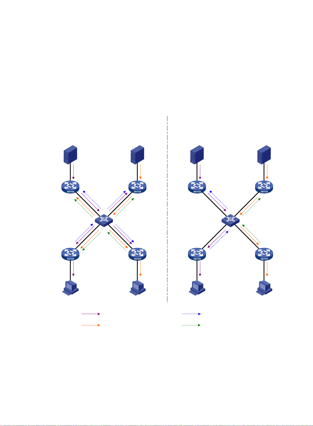
Configuring IPv6 PIM snooping
Overview
IPv6 PIM snooping runs on Layer 2 devices. It works with MLD snooping to analyze received IPv6
PIM messages, and adds the ports that are interested in specific multicast data to an IPv6 PIM
snooping routing entry. In this way, the multicast data can be forwarded to only the ports that are
interested in the data.
Figure 27 Multicast packet transmission without or with IPv6 PIM snooping
Source 1
IPv6 PIM
router 1
IPv6 PIM
router 3
IPv6 multicast packet transmission
when only MLD snooping runs
Source 2
Layer 2 switch
IPv6 PIM
router 2
IPv6 PIM
router 4
IPv6 multicast packet transmission when
MLD snooping and IPv6 PIM snooping both run
Source 1 Source 2
IPv6 PIM
router 1
Layer 2 switch
IPv6 PIM
router 3
IPv6 PIM
router 2
IPv6 PIM
router 4
Receiver 1 Receiver 2
IPv6 multicast packets (S1, G1) Join message (S1, G1)
IPv6 multicast packets (S2, G2) Join message (S2, G2)
Receiver 1 Receiver 2
As shown in Figure 27, Source 1 sends multicast data to multicast group G1, and Source 2 sends
multicast data to multicast group G2. Receiver 1 belongs to G1, and Receiver 2 belongs to G2. The
Layer 2 switch's interfaces that connect to the IPv6 PIM-capable routers are in the same VLAN.
• When the Layer 2 switch only runs MLD snooping, it performs the following actions:
a. Maintains the router ports according to the received IPv6 PIM hello messages that IPv6
PIM-capable routers send.
79
Page 85

b. Broadcasts all other types of received IPv6 PIM messages except PIM hello messages in
the VLAN.
c. Forwards all multicast data to all router ports in the VLAN.
Each IPv6 PIM-capable router in the VLAN, whether interested in the multicast data or not,
can receive all multicast data and all IPv6 PIM messages except IPv6 PIM hello messages.
• When the Layer 2 switch runs both MLD snooping and IPv6 PIM snooping, it performs the
following actions:
a. Examines whether an IPv6 PIM router is interested in the multicast data destined for a
multicast group according to the received IPv6 PIM messages that the router sends.
b. Adds only the ports that connect to the router and are interested in the data to an IPv6 PIM
snooping routing entry.
c. Forwards IPv6 PIM messages and the multicast data only to the router according to the
multicast forwarding entry, which saves network bandwidth.
For more information about MLD snooping and the router port, see "Configuring MLD snooping."
IPv6 PIM sno
oping can run in IPv6 PIM-SM and IPv6 PIM-SSM networks. Do not configure IPv6 PIM
snooping in IPv6 PIM-DM or IPv6 BIDIR-PIM networks.
Configuring IPv6 PIM snooping
To configure IPv6 PIM snooping for a VLAN, enable MLD snooping globally on the Layer 2 device,
and enable MLD snooping and IPv6 PIM snooping for the VLAN.
After you enable IPv6 PIM snooping for a VLAN, IPv6 PIM snooping works only on the member
interfaces of the VLAN.
To configure IPv6 PIM snooping:
Step Command Remarks
1. Enter system view.
2. Enable MLD snooping
globally and enter MLD
-snooping view.
3. Return to system view.
4. Enter VLAN view.
5. Enable MLD snooping for
the VLAN.
6. Enable IPv6 PIM snooping
for the VLAN.
7. (Optional.) Set the aging
time for the IPv6 PIM
snooping global neighbor
ports on the new master
device in IRF master
election.
8. (Optional.) Set the aging
time for the IPv6 PIM
snooping global
downstream ports and
global router ports on the
new master device in IRF
master election.
system-view
mld-snooping
quit
vlan
mld-snooping enable
ipv6 pim-snooping enable
ipv6 pim-snooping
graceful-restart
neighbor-aging-time
ipv6 pim-snooping
graceful-restart join-aging-time
interval
vlan-id
interval
N/A
By default, MLD snooping is
disabled.
N/A
N/A
By default, MLD snooping is
disabled in a VLAN.
By default, IPv6 PIM snooping is
disabled in a VLAN.
The default setting is 105
seconds.
A global neighbor port is a Layer
2 aggregate interface that acts as
a neighbor port.
The default setting is 210
seconds.
A global downstream port or a
global router port is a Layer 2
aggregate interface that acts as a
downstream port or router port.
80
Page 86
Displaying and maintaining IPv6 PIM snooping
Execute display commands in any view and reset commands in user view.
Task Command
Display IPv6 PIM snooping neighbor
information.
display ipv6 pim-snooping neighbor
slot-number ] [
verbose
]
[
vlan
vlan-id ] [
slot
Display IPv6 PIM snooping routing
entries.
Display IPv6 PIM snooping router
port information.
display ipv6 pim-snooping routing-table
slot-number ] [
verbose
]
display ipv6 pim-snooping router-port
slot-number ]
[
vlan
vlan
[
vlan-id ] [
Display statistics for the IPv6 PIM
messages learned through IPv6 PIM
display ipv6 pim-snooping statistics
snooping.
Clear statistics for the IPv6 PIM
messages learned through IPv6 PIM
reset ipv6 pim-snooping statistics
snooping.
IPv6 PIM snooping configuration example
Network requirements
As shown in Figure 28:
• Source 1 sends multicast data to IPv6 multicast group FF1E::101, and Source 2 sends
multicast data to IPv6 multicast group FF2E::101.
• Receiver 1 belongs to IPv6 multicast group FF1E::101, and Receiver 2 belongs to IPv6
multicast group FF2E::101.
• Router C and Router D run MLD on GigabitEthernet 1/0/1. Router A, Router B, Router C, and
Router D run IPv6 PIM-SM.
• GigabitEthernet 1/0/2 on Router A acts as a C-BSR and a C-RP.
vlan-id ] [
slot
slot
Configure MLD snooping and IPv6 PIM snooping on Switch A so that Switch A forwards IPv6
multicast packets to only the routers that are interested in the multicast data.
Figure 28 Network diagram
Source 1
1::100/64
Source 2
2::100/64
Router A
GE1/0/1
1::1/64
GE1/0/1
2::1/64
Router B Router D
GE1/0/2
1001::1/64
GE1/0/1
GE1/0/2
GE1/0/2
1001::2/64
1001::3/64
Switch A
GE1/0/3
GE1/0/4
1001::4/64
GE1/0/2
GE1/0/2
81
Router C
GE1/0/1
3::1/64
GE1/0/1
4::1/64
Receiver 1
3::100/64
Receiver 2
4::100/64
Page 87

Configuration procedure
1. Assign an IPv6 address and prefix length for each interface according to Figure 28. (Details not
shown.)
2. Configure RIPng on all the routers. (Details not shown.)
3. Configure Router A:
# Enable IPv6 multicast routing globally.
<RouterA> system-view
[RouterA] ipv6 multicast routing
[RouterA-mrib6] quit
# Enable IPv6 PIM-SM on each interface.
[RouterA] interface gigabitethernet 1/0/1
[RouterA-GigabitEthernet1/0/1] ipv6 pim sm
[RouterA-GigabitEthernet1/0/1] quit
[RouterA] interface gigabitethernet 1/0/2
[RouterA-GigabitEthernet1/0/2] ipv6 pim sm
[RouterA-GigabitEthernet1/0/2] quit
# Configure GigabitEthernet 1/0/2 as a C-BSR and a C-RP.
[RouterA] ipv6 pim
[RouterA-pim6] c-bsr 1001::1
[RouterA-pim6] c-rp 1001::1
[RouterA-pim6] quit
4. Configure Router B:
# Enable IPv6 multicast routing globally.
<RouterB> system-view
[RouterB] ipv6 multicast routing
[RouterB-mrib6] quit
# Enable IPv6 PIM-SM on each interface.
[RouterB] interface gigabitethernet 1/0/1
[RouterB-GigabitEthernet1/0/1] ipv6 pim sm
[RouterB-GigabitEthernet1/0/1] quit
[RouterB] interface gigabitethernet 1/0/2
[RouterB-GigabitEthernet1/0/2] ipv6 pim sm
[RouterB-GigabitEthernet1/0/2] quit
5. Configure Router C:
# Enable IPv6 multicast routing globally.
<RouterC> system-view
[RouterC] ipv6 multicast routing
[RouterC-mrib6] quit
# Enable MLD on GigabitEthernet 1/0/1.
[RouterC] interface gigabitethernet 1/0/1
[RouterC-GigabitEthernet1/0/1] mld enable
[RouterC-GigabitEthernet1/0/1] quit
# Enable IPv6 PIM-SM on GigabitEthernet 1/0/2.
[RouterC] interface gigabitethernet 1/0/2
[RouterC-GigabitEthernet1/0/2] ipv6 pim sm
[RouterC-GigabitEthernet1/0/2] quit
6. Configure Router D:
82
Page 88

# Enable IPv6 multicast routing globally.
<RouterD> system-view
[RouterD] ipv6 multicast routing
[RouterD-mrib6] quit
# Enable MLD on GigabitEthernet 1/0/1.
[RouterD] interface gigabitethernet 1/0/1
[RouterD-GigabitEthernet1/0/1] mld enable
[RouterD-GigabitEthernet1/0/1] quit
# Enable IPv6 PIM-SM on GigabitEthernet 1/0/2.
[RouterD] interface gigabitethernet 1/0/2
[RouterD-GigabitEthernet1/0/2] ipv6 pim sm
[RouterD-GigabitEthernet1/0/2] quit
7. Configure Switch A:
# Enable MLD snooping globally.
<SwitchA> system-view
[SwitchA] mld-snooping
[SwitchA-mld-snooping] quit
# Create VLAN 100, assign GigabitEthernet 1/0/1 through GigabitEthernet 1/0/4 to this VLAN,
and enable MLD snooping and IPv6 PIM snooping for the VLAN.
[SwitchA] vlan 100
[SwitchA-vlan100] port gigabitethernet 1/0/1 to gigabitethernet 1/0/4
[SwitchA-vlan100] mld-snooping enable
[SwitchA-vlan100] ipv6 pim-snooping enable
[SwitchA-vlan100] quit
Verifying the configuration
# On Switch A, display information about IPv6 PIM snooping neighbors for VLAN 100.
[SwitchA] display ipv6 pim-snooping neighbor vlan 100
Total 4 neighbors.
VLAN 100: Total 4 neighbors.
FE80::1
Slots (0 in total):
Ports (1 in total):
GE1/0/1 (00:32:43)
FE80::2
Slots (0 in total):
Ports (1 in total):
GE1/0/2 (00:32:43)
FE80::3
Slots (0 in total):
Ports (1 in total):
GE1/0/3 (00:32:43)
FE80::4
Slots (0 in total):
Ports (1 in total):
GE1/0/4 (00:32:43)
83
Page 89

The output shows that Router A, Router B, Router C, and Router D are IPv6 PIM snooping
neighbors.
# On Switch A, display IPv6 PIM snooping routing entries for VLAN 100.
[SwitchA] display pim-snooping ipv6 routing-table vlan 100
Total 2 entries.
FSM flag: NI-no info, J-join, PP-prune pending
VLAN 100: Total 2 entries.
(*, FF1E::101)
Upstream neighbor: FE80::1
Upstream Slots (0 in total):
Upstream ports (1 in total):
GE1/0/1
Downstream Slots (0 in total):
Downstream ports (1 in total):
GE1/0/3
Expires: 00:03:01, FSM: J
(*, FF2E::101)
Upstream neighbor: FE80::2
Upstream Slots (0 in total):
Upstream ports (1 in total):
GE1/0/2
Downstream Slots (0 in total):
Downstream ports (1 in total):
GE1/0/4
Expires: 00:03:01, FSM: J
The output shows the following:
• Switch A will forward the multicast data intended for IPv6 multicast group FF1E::101 to only
Router C.
• Switch A will forward the multicast data intended for IPv6 multicast group FF2E::101 to only
Router D.
Troubleshooting IPv6 PIM snooping
This section describes common IPv6 PIM snooping problems and how to troubl eshoot them.
IPv6 PIM snooping does not work on a Layer 2 device
Symptom
IPv6 PIM snooping does not work on a Layer 2 device.
Solution
1. Use the display current-configuration command to display information about MLD snooping
and IPv6 PIM snooping.
2. If MLD snooping is not enabled, enable MLD snooping globally, and then enable MLD snooping
and IPv6 PIM snooping for the VLAN.
3. If IPv6 PIM snooping is not enabled, enable IPv6 PIM snooping for the VLAN.
4. If the problem persists, contact Hewlett Packard Enterprise Support.
84
Page 90

Configuring IPv6 multicast VLANs
Overview
As shown in Figure 29, Host A, Host B, and Host C are in different VLANs and the same IPv6
multicast group. When Switch A (Layer 3 device) receives IPv6 multicast data for that group, it sends
three copies of the data to Switch B (Layer 2 device). This occupies a large amo unt of bandwidth and
increases the burden on the Layer 3 device.
Figure 29 Multicast transmission without the IPv6 multicast VLAN feature
IPv6 Multicast packets
VLAN 2
VLAN 3
VLAN 4
Source
Switch A
MLD querier
Switch B
After an IPv6 multicast VLAN is configured on Switch B, Switch A sends one copy of the IPv6
multicast data to the IPv6 multicast VLAN on Switch B. This saves network bandwidth and lessens
the burden on the Layer 3 device.
IPv6 multicast VLANs include sub-VLAN-based IPv6 multicast VLANs and port-based IPv6 multicast
VLANs.
Sub-VLAN-based IPv6 multicast VLAN
VLAN 2
Receiver
Host A
VLAN 3
Receiver
Host B
VLAN 4
Receiver
Host C
As shown in Figure 30:
• Host A, Host B, and Host C are in VLAN 2 through VLAN 4, respectively.
• On Switch B, VLAN 10 is an IPv6 multicast VLAN.
VLAN 2 through VLAN 4 are sub-VLANs of VLAN 10.
MLD snooping is enabled for the multicast VLAN and its sub-VLANs.
85
Page 91

Figure 30 Sub-VLAN-based multicast VLAN
MLD snooping manages router ports in the IPv6 multicast VLAN and member ports in each
sub-VLAN. When Switch A receives IPv6 multicast data from the multicast source, it sends only one
copy of the IPv6 multicast data to the IPv6 multicast VLAN on Switch B. Then, Switch B sends a
separate copy to each sub-VLAN of the IPv6 multicast VLAN.
Port-based IPv6 multicast VLAN
As shown in Figure 31:
• Host A, Host B, and Host C are in VLAN 2 through VLAN 4, respectively.
• On Switch B, VLAN 10 is an IPv6 multicast VLAN.
All the user ports are hybrid ports and are assigned to VLAN 10.
MLD snooping is enabled for the IPv6 multicast VLAN and VLAN 2 through VLAN 4.
Figure 31 Port-based IPv6 multicast VLAN
IPv6 Multicast packets
VLAN 10 (IPv6 Multicast VLAN)
Source
MLD snooping manages the router ports and member ports in the IPv6 multicast VLAN. When
Switch B receives an MLD message from a user port, it tags the message with the IPv6 multicast
VLAN ID and sends it to the MLD querier. When Switch A receives IPv6 multicast data from the
multicast source, it sends only one copy of the IPv6 multicast data to the IPv6 multicast VLAN on
Switch B. Then, Switch B sends a sep arate copy to each user port in the IPv6 multicast VLAN.
Switch A
MLD querier
GE1/0/1
Switch B
GE1/0/2
GE1/0/3
GE1/0/4
VLAN 2
Receiver
Host A
VLAN 3
Receiver
Host B
VLAN 4
Receiver
Host C
86
Page 92

IPv6 multicast VLAN configuration task list
Task at a glance
(Required.) Perform one of the following tasks:
• Configuring a sub-VLAN-based IPv6 multicast VLAN
• Configuring a port-based IPv6 multicast VLAN
{ Configuring user port attributes
{ Assigning user ports to an IPv6 multicast VLAN
(Optional.) Setting the maximum number of IPv6 multicast VLAN forwarding entries
If you have configured both a sub-VLAN-based IPv6 multicast VLAN and a port-based IPv6 multicast
VLAN on a device, the port-based IPv6 multicast VLAN configuration takes effect.
Configuring a sub-VLAN-based IPv6 multicast VLAN
Y ou must first configure a VLAN as an IPv6 mult icast VLAN, and then assign the VLANs that contain
multicast receivers to the IPv6 multicast VLAN as sub-VLANs.
Configuration prerequisites
Before you configure a sub-VLAN-based IPv6 multicast VLAN, complete the following tasks:
• Create VLANs as required.
• Enable MLD snooping for the VLAN to be configured as the IPv6 multicast VLAN, and for the
VLANs to be configured as sub-VLANs.
Configuration guidelines
When you configure a sub-VLAN-based IPv6 multicast VLAN, follow these guidelines:
• The VLAN to be configured as the IPv6 multicast VLAN must exist.
• A VLAN to be configure d as a sub-VLAN must exist and cannot be a n IPv6 multicast VLAN or a
sub-VLAN of any other IPv6 multicast VLANs.
• The total number of IPv6 multicast VLANs on a device cannot exceed the upper limit.
Configuration procedure
To configure a sub-VLAN-based IPv6 multicast VLAN:
Step Command Remarks
1. Enter system view.
2. Configure a VLAN as an
IPv6 multicast VLAN and
enter its view.
3. Assign the specified VLANs
to the IPv6 multicast VLAN
as sub-VLANs.
system-view
ipv6 multicast-vlan
vlan-id
subvlan
vlan-list
N/A
By default, a VLAN is not an IPv6
multicast VLAN.
By default, an IPv6 multicast VLAN does
not have any sub-VLANs.
87
Page 93

Configuring a port-based IPv6 multicast VLAN
To configure a port-based IPv6 multicast VLAN, perform the following steps:
1. Configure a VLAN as an IPv6 multicast VLAN.
2. Configure the attributes for user ports that are connected to the multicast receivers.
3. Assign the user ports to the IPv6 multicast VLAN.
You can assign a port to an IPv6 multicast VLAN only when the port is an Ethernet port or a Layer 2
aggregate interface.
Configuration prerequisites
Before you configure a port-based IPv6 multicast VLAN, complete the following tasks:
• Create VLANs as required.
• Enable MLD snooping for the VLAN to be configured as the IPv6 multicast VLAN.
• Enable MLD snooping for all the VLANs that contain the multicast receivers.
Configuring user port attributes
Step Command Remarks
1. Enter system view.
2. Enter interface view.
3. Configure the link type of the
user port as hybrid.
4. Specify the PVID of the
current user port as the
VLAN to which the user port
belongs.
5. Configure the current user
port to permit IPv6 multicast
VLAN and to untag the
packets.
system-view
interface
interface-number
port link-type hybrid
port hybrid pvid vlan
port hybrid vlan
untagged
interface-type
vlan-id-list
vlan-id
N/A
N/A
The default setting is
For more information about this
command, see Layer 2—LAN
Switching Command Reference.
By default, the PVID for a hybrid
port is VLAN 1.
For more information about this
command, see Layer 2—LAN
Switching Command Reference.
By default, a hybrid port permits
only VLAN 1.
For more information about this
command, see Layer 2—LAN
Switching Command Reference.
Assigning user ports to an IPv6 multicast VLAN
You can either assign the user ports to the IPv6 multicast VLAN in IPv6 multicast VLAN view, or
assign the user ports to the IPv6 multicast VLAN in interface view.
access
.
When you perform this task, follow these guidelines:
• The VLAN to be configured as an IPv6 multicast VLAN must exist.
• A port can bel ong to only one IPv6 multicast VLAN.
88
Page 94

Assigning ports to an IPv6 multicast VLAN in IPv6 multicast VLAN view
Step Command Remarks
1. Enter system view.
2. Configure an IPv6 VLAN as
an IPv6 multicast VLAN and
enter its view.
3. Assign ports to the IPv6
multicast VLAN.
system-view
ipv6 multicast-vlan
port
interface-list
vlan-id
N/A
By default, a VLAN is not an IPv6
multicast VLAN.
By default, an IPv6 multicast VLAN
does not have any user ports.
Assigning a port to an IPv6 multicast VLAN in interface view
Step Command Remarks
1. Enter system view.
2. Configure an IPv6 VLAN as
an IPv6 multicast VLAN and
enter its view.
3. Return to system view.
4. Enter interface view.
system-view
ipv6 multicast-vlan
quit
interface
interface-type interface-number N/A
vlan-id
N/A
By default, a VLAN is not
an IPv6 multicast VLAN.
N/A
5. Assign the current port to the
IPv6 multicast VLAN.
ipv6 port multicast-vlan
vlan-id
By default, a user port
does not belong to any
IPv6 multicast VLAN.
Setting the maximum number of IPv6 multicast VLAN forwarding entries
You can set the maximum number of IPv6 multicast VLAN forwarding entries on the switch. When
the upper limit is reached, the switch does not create IPv6 multicast VLAN forwarding entries until
some entries age out or are manually removed.
If the total number of entries exceeds the upper limit value that you are setting, the system does not
automatically remove existing entries or create new entries. As a best practice, manually remove
some entries to allow new entries to be created.
To set the maximum number of IPv6 multicast VLAN forwarding entries:
Step Command Remarks
1. Enter system view.
2. Set the maximum number of
IPv6 multicast VLAN
forwarding entries.
system-view
ipv6 multicast-vlan entry-limit
limit
N/A
The default setting is 256.
Displaying and maintaining IPv6 multicast VLANs
Execute display commands in any view and reset commands in user view.
Task Command
Display information about IPv6
multicast VLANs.
display ipv6 multicast-vlan
89
[ vlan-id ]
Page 95

Task Command
Display information about IPv6
multicast groups in IPv6 multicast
VLANs.
display ipv6 multicast-vlan group
ipv6-group-address |
slot
slot-number |
[ ipv6-source-address |
verbose
|
vlan
vlan-id ] *
Display IPv6 multicast VLAN
forwarding entries.
Clear IPv6 multicast groups in IPv6
multicast VLANs.
display ipv6 multicast-vlan forwarding-table
[ ipv6-source-address [ prefix-length ] | ipv6-group-address
[ prefix-length ] |
reset ipv6 multicast-vlan group
[ prefix-length ] | ipv6-source-address [ prefix-length ] |
*
slot
slot-number |
subvlan
[ ipv6-group-address
vlan-id |
vlan
vlan
IPv6 multicast VLAN configuration examples
Sub-VLAN-based IPv6 multicast VLAN configuration example
Network requirements
As shown in Figure 32:
• MLDv1 runs on Layer 3 device Switch A, and MLDv1 snooping runs on Layer 2 device Switch
B.
• Switch A acts as the MLD querier.
• The IPv6 multicast source sends IPv6 multicast data to IPv6 multicast group FF1E::101. Host A,
Host B, and Host C are receivers. They belong to VLAN 2 through VLAN 4, respectively.
vlan-id ] *
vlan-id ]
Configure a sub-VLAN-based IPv6 multicast VLAN on Switch B to achieve the following goals:
• Switch A sends the IPv6 multicast data to Switch B through the IPv6 multicast VLAN.
• Switch B forwards the IPv6 multicast data to the receivers in different user VLANs.
Figure 32 Network diagram
90
Page 96

Configuration procedure
1. Configure Switch A:
# Enable IPv6 multicast routing globally.
<SwitchA> system-view
[SwitchA] ipv6 multicast routing
[SwitchA-mrib6] quit
# Create VLAN 20, and assign GigabitEthernet 1/0/2 to this VLAN.
[SwitchA] vlan 20
[SwitchA-vlan20] port gigabitethernet 1/0/2
[SwitchA-vlan20] quit
# Assign an IPv6 address to VLAN-interface 20, and enable IPv6 PIM-DM.
[SwitchA] interface vlan-interface 20
[SwitchA-Vlan-interface20] ipv6 address 1::2 64
[SwitchA-Vlan-interface20] ipv6 pim dm
[SwitchA-Vlan-interface20] quit
# Create VLAN 10.
[SwitchA] vlan 10
[SwitchA-vlan10] quit
# Configure GigabitEthernet 1/0/1 as a hybrid port, and assign it to VLAN 10 as a tagged VLAN
member.
[SwitchA] interface gigabitethernet 1/0/1
[SwitchA-GigabitEthernet1/0/1] port link-type hybrid
[SwitchA-GigabitEthernet1/0/1] port hybrid vlan 10 tagged
[SwitchA-GigabitEthernet1/0/1] quit
# Assign an IPv6 address to VLAN-interface 10, and enable MLD on this interface.
[SwitchA] interface vlan-interface 10
[SwitchA-Vlan-interface10] ipv6 address 2001::1 64
[SwitchA-Vlan-interface10] mld enable
[SwitchA-Vlan-interface10] quit
2. Configure Switch B:
# Enable MLD snooping globally.
<SwitchB> system-view
[SwitchB] mld-snooping
[SwitchB-mld-snooping] quit
# Create VLAN 2, assign GigabitEthernet 1/0/2 to this VLAN, and enable MLD snooping for this
VLAN.
[SwitchB] vlan 2
[SwitchB-vlan2] port gigabitethernet 1/0/2
[SwitchB-vlan2] mld-snooping enable
[SwitchB-vlan2] quit
# Create VLAN 3, assign GigabitEthernet 1/0/3 to this VLAN, and enable MLD snooping for this
VLAN.
[SwitchB] vlan 3
[SwitchB-vlan3] port gigabitethernet 1/0/3
[SwitchB-vlan3] mld-snooping enable
[SwitchB-vlan3] quit
# Create VLAN 4, assign GigabitEthernet1/0/4 to this VLAN, and enable MLD snooping for this
VLAN.
91
Page 97

[SwitchB] vlan 4
[SwitchB-vlan4] port gigabitethernet 1/0/4
[SwitchB-vlan4] mld-snooping enable
[SwitchB-vlan4] quit
# Create VLAN 10, and enable MLD snooping for this VLAN.
[SwitchB] vlan 10
[SwitchB-vlan10] mld-snooping enable
[SwitchB-vlan10] quit
# Configure GigabitEthernet 1/0/1 as a hybrid port, and assign it to VLAN 10 as a tagged VLAN
member.
[SwitchB] interface gigabitethernet 1/0/1
[SwitchB-GigabitEthernet1/0/1] port link-type hybrid
[SwitchB-GigabitEthernet1/0/1] port hybrid vlan 10 tagged
[SwitchB-GigabitEthernet1/0/1] quit
# Configure VLAN 10 as an IPv6 multicast VLAN, and configure VLAN 2 through VLAN 4 as
sub-VLANs.
[SwitchB] ipv6 multicast-vlan 10
[SwitchB-ipv6-mvlan-10] subvlan 2 to 4
[SwitchB-ipv6-mvlan-10] quit
Verifying the configuration
# Display information about all IPv6 multicast VLANs on Switch B.
[SwitchB] display ipv6 multicast-vlan
Total 1 IPv6 multicast VLANs.
IPv6 multicast VLAN 10:
Sub-VLAN list(3 in total):
2-4
Port list(0 in total):
# Display information about IPv6 multicast groups in IPv6 multicast VLANs on Switch B.
[SwitchB] display ipv6 multicast-vlan group
Total 1 entries.
IPv6 multicast VLAN 10: Total 1 entries.
(::, FF1E::101)
Sub-VLANs (3 in total):
VLAN 2
VLAN 3
VLAN 4
The output shows that IPv6 multicast group FF1E::101 belongs to IPv6 multicast VLAN 10. IPv6
multicast VLAN 10 contains sub-VLANs VLAN 2 through VLAN 4. Switch B will replicate the IPv6
multicast data of VLAN 10 to VLAN 2 through VLAN 4.
Port-based IPv6 multicast VLAN configuration example
Network requirements
As shown in Figure 33:
• MLDv1 runs on Switch A. MLDv1 snooping runs on Switch B.
92
Page 98
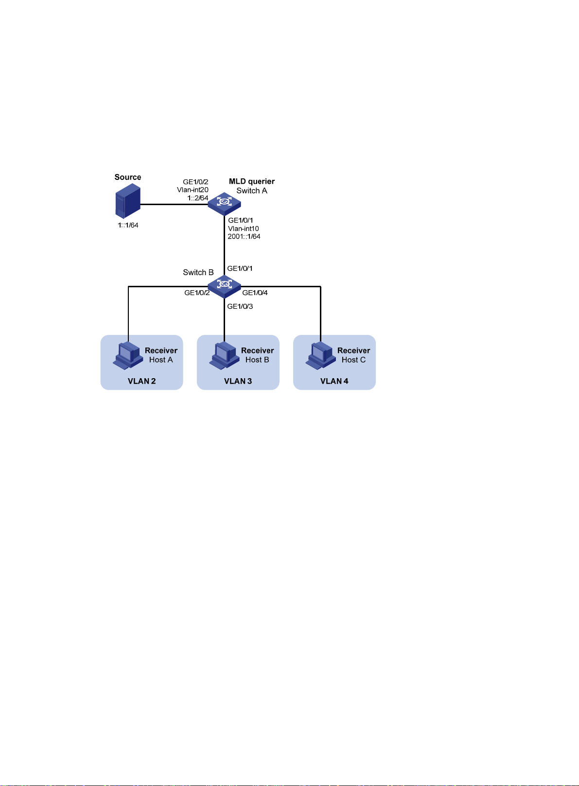
• Switch A acts as the MLD querier.
• The IPv6 multicast source sends IPv6 multicast data to IPv6 multicast group FF1E::101. Host A,
Host B, and Host C are receivers. They belong to VLAN 2 through VLAN 4, respectively.
Configure a port-based IPv6 multicast VLAN on Switch B to achieve the following goals:
• Switch A sends IPv6 multicast data to Switch B through the IPv6 multicast VLAN.
• Switch B forwards the IPv6 multicast data to the receivers in different user VLANs.
Figure 33 Network diagram
Configuration procedure
1. Configure Switch A:
# Enable IPv6 multicast routing globally.
<SwitchA> system-view
[SwitchA] ipv6 multicast routing
[SwitchA-mrib6] quit
# Create VLAN 20, and assign GigabitEthernet 1/0/2 to this VLAN.
[SwitchA] vlan 20
[SwitchA-vlan20] port gigabitethernet 1/0/2
[SwitchA-vlan20] quit
# Assign an IPv6 address to VLAN-interface 20, and enable IPv6 PIM-DM on this interface.
[SwitchA] interface vlan-interface 20
[SwitchA-Vlan-interface20] ipv6 address 1::2 64
[SwitchA-Vlan-interface20] ipv6 pim dm
[SwitchA-Vlan-interface20] quit
# Create VLAN 10, and assign GigabitEthernet 1/0/1 to the VLAN.
[SwitchA] vlan 10
[SwitchA-vlan10] port gigabitethernet 1/0/1
[SwitchA-vlan10] quit
# Assign an IPv6 address to VLAN-interface 10, and enable MLD on this interface.
[SwitchA] interface vlan-interface 10
[SwitchA-Vlan-interface10] ipv6 address 2001::1 64
93
Page 99

[SwitchA-Vlan-interface10] mld enable
[SwitchA-Vlan-interface10] quit
2. Configure Switch B:
# Enable MLD snooping globally.
<SwitchB> system-view
[SwitchB] mld-snooping
[SwitchB-mld-snooping] quit
# Create VLAN 10, assign GigabitEthernet 1/0/1 to VLAN 10, and enable MLD snooping for this
VLAN.
[SwitchB] vlan 10
[SwitchB-vlan10] port gigabitethernet 1/0/1
[SwitchB-vlan10] mld-snooping enable
[SwitchB-vlan10] quit
# Create VLAN 2, and enable MLD snooping for the VLAN.
[SwitchB] vlan 2
[SwitchB-vlan2] mld-snooping enable
[SwitchB-vlan2] quit
# Create VLAN 3, and enable MLD snooping for the VLAN.
[SwitchB] vlan 3
[SwitchB-vlan3] mld-snooping enable
[SwitchB-vlan3] quit
# Create VLAN 4, and enable MLD snooping for the VLAN.
[SwitchB] vlan 4
[SwitchB-vlan4] mld-snooping enable
[SwitchB-vlan4] quit
# Configure GigabitEthernet 1/0/2 as a hybrid port, and configure VLAN 2 as the PVID of the
hybrid port.
[SwitchB] interface gigabitethernet 1/0/2
[SwitchB-GigabitEthernet1/0/2] port link-type hybrid
[SwitchB-GigabitEthernet1/0/2] port hybrid pvid vlan 2
# Assign GigabitEthernet 1/0/2 to VLAN 2 and VLAN 10 as an untagged VLAN member.
[SwitchB-GigabitEthernet1/0/2] port hybrid vlan 2 untagged
[SwitchB-GigabitEthernet1/0/2] port hybrid vlan 10 untagged
[SwitchB-GigabitEthernet1/0/2] quit
# Configure GigabitEthernet 1/0/3 as a hybrid port, and configure VLAN 3 as the PVID of the
hybrid port.
[SwitchB] interface gigabitethernet 1/0/3
[SwitchB-GigabitEthernet1/0/3] port link-type hybrid
[SwitchB-GigabitEthernet1/0/3] port hybrid pvid vlan 3
# Assign GigabitEthernet 1/0/3 to VLAN 3 and VLAN 10 as an untagged VLAN member.
[SwitchB-GigabitEthernet1/0/3] port hybrid vlan 3 untagged
[SwitchB-GigabitEthernet1/0/3] port hybrid vlan 10 untagged
[SwitchB-GigabitEthernet1/0/3] quit
# Configure GigabitEthernet 1/0/4 as a hybrid port, and configure VLAN 4 as the PVID of the
hybrid port.
[SwitchB] interface gigabitethernet 1/0/4
[SwitchB-GigabitEthernet1/0/4] port link-type hybrid
[SwitchB-GigabitEthernet1/0/4] port hybrid pvid vlan 4
94
Page 100

# Assign GigabitEthernet 1/0/4 to VLAN 4 and VLAN 10 as an untagged VLAN member.
[SwitchB-GigabitEthernet1/0/4] port hybrid vlan 4 untagged
[SwitchB-GigabitEthernet1/0/4] port hybrid vlan 10 untagged
[SwitchB-GigabitEthernet1/0/4] quit
# Configure VLAN 10 as an IPv6 multicast VLAN.
[SwitchB] ipv6 multicast-vlan 10
# Assign GigabitEthernet 1/0/2 and GigabitEthernet 1/0/3 to VLAN 10.
[SwitchB-ipv6-mvlan-10] port gigabitethernet 1/0/2 to gigabitethernet 1/0/3
[SwitchB-ipv6-mvlan-10] quit
# Assign GigabitEthernet 1/0/4 to VLAN 10.
[SwitchB] interface gigabitethernet 1/0/4
[SwitchB-GigabitEthernet1/0/4] ipv6 port multicast-vlan 10
[SwitchB-GigabitEthernet1/0/4] quit
Verifying the configuration
# Display information about IPv6 multicast VLANs on Switch B.
[SwitchB] display ipv6 multicast-vlan
Total 1 IPv6 multicast VLANs.
IPv6 multicast VLAN 10:
Sub-VLAN list(0 in total):
Port list(0 in total):
GE1/0/2
GE1/0/3
GE1/0/4
# Display information about MLD snooping group entries for dynamic IPv6 multicast groups on
Switch B.
[SwitchB] display mld-snooping group
Total 1 entries.
VLAN 2: Total 1 entries.
(::, FF1E::101)
Host slots (0 in total):
Host ports (3 in total):
GE1/0/2 (00:03:23)
GE1/0/3 (00:04:07)
GE1/0/4 (00:04:16)
The output shows that MLD snooping maintains the user ports in VLAN 10. Switch B will forward the
IPv6 multicast data of VLAN 10 through these user ports.
95
 Loading...