

Page 1

HP A3100 v2 Switch Series
Installation Guide
HP A3100-8 v2 SI Switch (JG221A)
HP A3100-16 v2 SI Switch (JG222A)
HP A3100-24 v2 SI Switch (JG223A)
HP A3100-8 v2 EI Switch (JD318B)
HP A3100-16 v2 EI Switch (JD319B)
HP A3100-24 v2 EI Switch (JD320B)
HP A3100-8-PoE v2 EI Switch (JD311B)
HP A3100-16-PoE v2 EI Switch (JD312B)
HP A3100-24-PoE v2 EI Switch (JD313B)
Part number: 5998-1961
Document version: 6W100-20110909
Page 2

Legal and notice information
© Copyright 2011 Hewlett-Packard Development Company, L.P.
No part of this documentation may be reproduced or transmitted in any form or by any means without
prior written consent of Hewlett-Packard Development Company, L.P.
The information contained herein is subject to change without notice.
HEWLETT-PACKARD COMPANY MAKES NO WARRANTY OF ANY KIND WITH REGARD TO THIS
MATERIAL, INCLUDING, BUT NOT LIMITED TO, THE IMPLIED WARRANTIES OF MERCHANTABILITY
AND FITNESS FOR A PARTICULAR PURPOSE. Hewlett-Packard shall not be liable for errors contained
herein or for incidental or consequential damages in connection with the furnishing, performance, or
use of this material.
The only warranties for HP products and services are set forth in the express warranty statements
accompanying such products and services. Nothing herein should be construed as constituting an
additional warranty. HP shall not be liable for technical or editorial errors or omissions contained
herein.
Page 3

Contents
Product overview·························································································································································· 1
Switch models····································································································································································1
Panel views ········································································································································································1
A3100-24 v2 SI/A3100-24 v2 EI ·························································································································1
A3100-16 v2 SI/A3100-16 v2 EI ·························································································································2
A3100-8 v2 SI/A3100-8 v2 EI ······························································································································3
A3100-24-PoE v2 EI ················································································································································3
A3100-16-PoE v2 EI ················································································································································4
A3100-8-PoE v2 EI···················································································································································5
Preparing for installation ············································································································································· 7
Safety recommendations ··················································································································································7
Examining the installation site ·········································································································································7
Electricity safety ························································································································································7
ESD prevention ·························································································································································7
Laser safety································································································································································8
Temperature/humidity ·············································································································································8
Cleanness··································································································································································9
EMI·············································································································································································9
Grounding······························································································································································ 10
Cooling··································································································································································· 10
Space······································································································································································ 10
Installation tools······························································································································································ 11
Installing the switch····················································································································································12
Installing the switch························································································································································ 12
Selecting an installation method·························································································································· 12
Installation accessories ·········································································································································13
Installing the switch into the 19-inch rack··········································································································· 15
Mounting the switch on a workbench ················································································································· 20
Grounding the switch ···················································································································································· 21
Grounding cable ··················································································································································· 21
Grounding the switch with a grounding strip····································································································· 21
Grounding the switch with a grounding conductor buried in the earth ground············································· 23
Grounding the switch by using the AC power cord·························································································· 24
Connecting the power cord ·········································································································································· 24
Connecting an AC power cord to the switch····································································································· 25
Connecting the DC power cord··························································································································· 25
Verifying the installation················································································································································ 26
Accessing the switch for the first time·······················································································································27
Setting up the configuration environment···················································································································· 27
Connecting the console cable ······································································································································27
Console cable························································································································································ 27
Connection procedure ·········································································································································· 27
Setting terminal parameters ·········································································································································· 28
Powering on the switch·················································································································································· 31
Verification before power-on ·······························································································································31
Powering on the switch········································································································································· 31
Initially configuring the switch ······································································································································ 32
i
Page 4

Configuring a login authentication method········································································································ 32
Configuring the basic access function ················································································································33
Connecting the switch to the network·······················································································································34
Connecting your switch to the network through twisted pair cables ········································································ 34
Connecting your switch to the network through optical fibers ·················································································· 34
Installing an SFP transceiver module ··················································································································· 35
Connecting an optical fiber connector to an SFP transceiver module····························································· 35
Troubleshooting··························································································································································37
Configuration terminal problems·································································································································· 37
Power supply failure ······················································································································································ 37
Interface failure······························································································································································· 38
PoE system failure ··························································································································································38
Support and other resources ·····································································································································39
Contacting HP ································································································································································ 39
Subscription service ·············································································································································· 39
Related information························································································································································ 39
Documents······························································································································································ 39
Websites································································································································································· 39
Conventions ···································································································································································· 40
Appendix A Technical specifications························································································································42
A3100 v2 SI Switch Series technical specifications ·································································································· 42
A3100 v2 EI Switch Series technical specifications ·································································································· 43
Non PoE switches technical specifications········································································································· 43
PoE switches technical specifications ·················································································································· 44
Appendix B Ports and LEDs·······································································································································47
Ports ················································································································································································· 47
Console port··························································································································································· 47
10/100Base-TX Ethernet port ······························································································································ 47
Combo interface···················································································································································· 47
10/100/1000Base-T Ethernet port ···················································································································· 48
100/1000Base-X SFP port··································································································································· 48
LEDs ················································································································································································· 49
LEDs for the non PoE switches······························································································································ 50
LEDs on the PoE switches······································································································································ 51
Appendix C Ethernet twisted pair cable ··················································································································53
Ethernet twisted pair cable············································································································································ 53
RJ-45 connector ····················································································································································· 53
Cable pinouts························································································································································· 53
Cable type······························································································································································ 53
Pin assignments······················································································································································ 55
Making an Ethernet twisted pair cable ··············································································································· 56
Index ···········································································································································································57
ii
Page 5
Product overview
Switch models
Table 1 Switch models in the HP A3100 v2 Switch Series
Sub-series Model Product code Description Alias
HP A3100 v2 SI
Switch Series
HP A3100 v2 EI
Switch Series
Non
PoE
Non
PoE
JG221A HP A3100-8 v2 SI Switch A3100-8 v2 SI
JG222A HP A3100-16 v2 SI Switch A3100-16 v2 SI
JG223A HP A3100-24 v2 SI Switch A3100-24 v2 SI
JD318B HP A3100-8 v2 EI Switch A3100-8 v2 EI
JD319B HP A3100-16 v2 EI Switch A3100-16 v2 EI
JD320B HP A3100-24 v2 EI Switch A3100-24 v2 EI
JD311B HP A3100-8-PoE v2 EI Switch A3100-8-PoE v2 EI
PoE
JD312B HP A3100-16-PoE v2 EI Switch A3100-16-PoE v2 EI
JD313B HP A3100-24-PoE v2 EI Switch A3100-24-PoE v2 EI
Panel views
A3100-24 v2 SI/A3100-24 v2 EI
Front panel
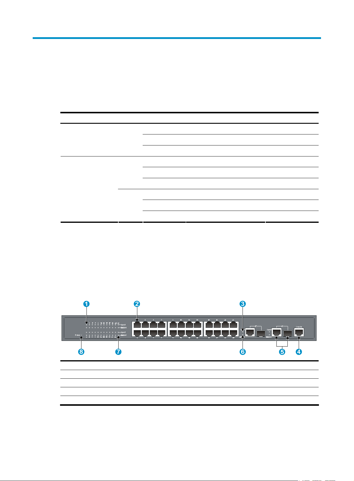
Figure 1 A3100-24 v2 SI/A3100-24 v2 EI front panel
(1) Speed LED for a 10/100Base-TX Ethernet port (2) 10/100Base-TX Ethernet port
(3) Speed LED for a combo interface (4) Console port
(5) Combo interface (10/100/1000Base-T Ethernet port on the left, 100/1000Base-X SFP port on the right)
(6) Link/Act LED for a combo interface
(7) Link/Act LED for a 10/100Base-TX Ethernet port (8) Power LED
1
Page 6
Rear panel
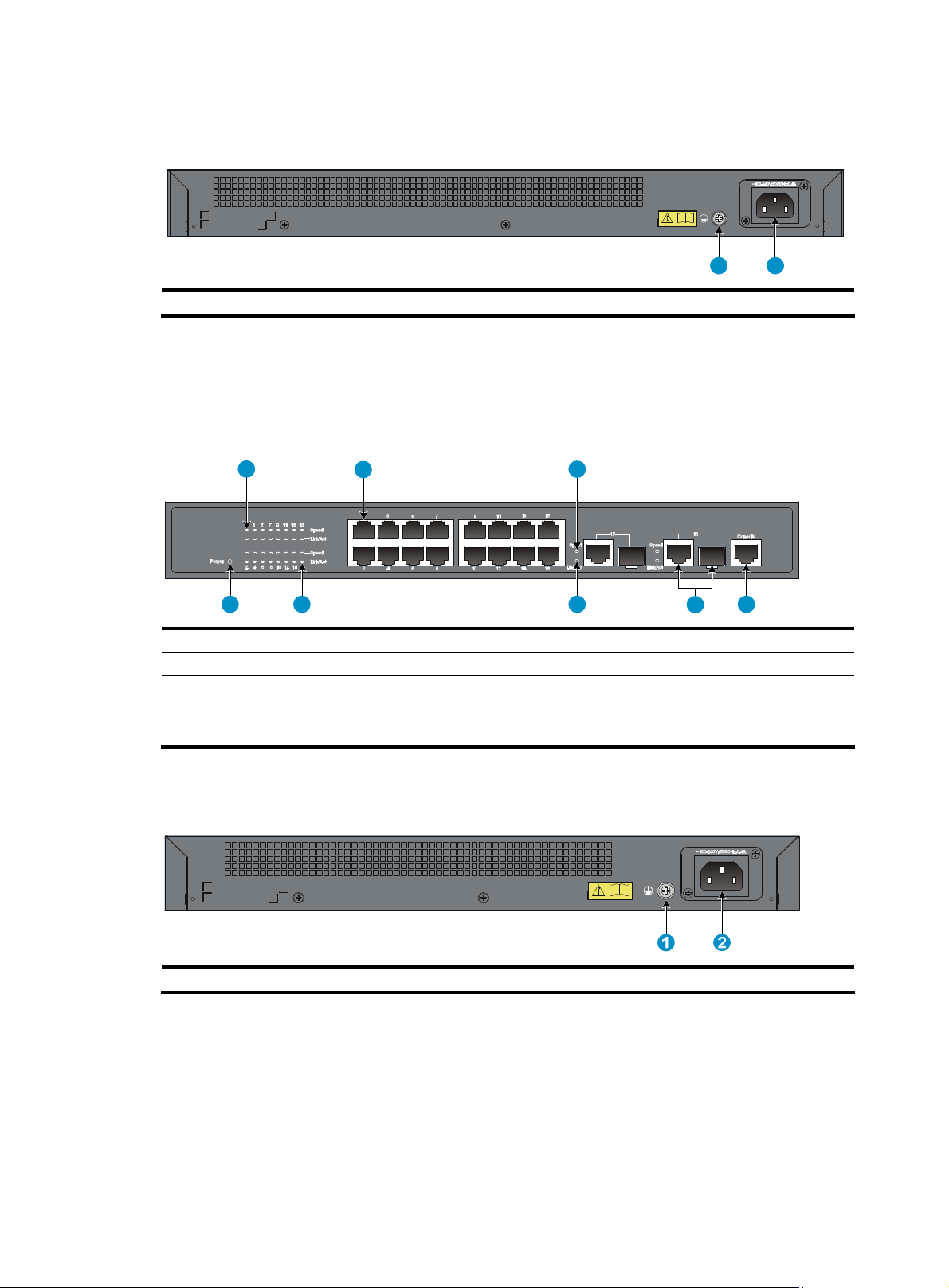
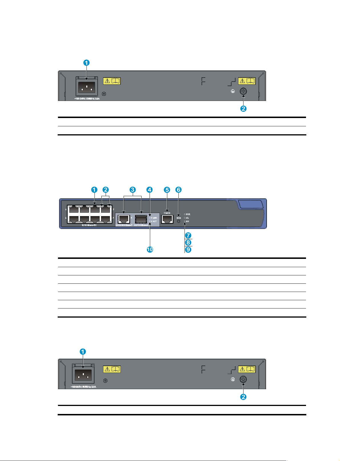
Figure 2 A3100-24 v2 SI/A3100-24 v2 EI rear panel
(1) Grounding screw (2) AC-input power receptacle
A3100-16 v2 SI/A3100-16 v2 EI
Front panel
Figure 3 A3100-16 v2 SI/A3100-16 v2 EI front panel
1
(1) Speed LED for a 10/100Base-TX Ethernet port (2) 10/100Base-TX Ethernet ports
(3) Speed LED for a combo interface (4) Console port
(5) Combo interface (10/100/1000Base-T Ethernet port on the left, 100/1000Base-X SFP port on the right)
(6) Link/Act LED for a combo interface (7) Link/Act LED for a 10/100Base-TX Ethernet port
(8) Power LED
2
1
2
3
678
5
4
Rear panel
Figure 4 A3100-16 v2 SI/A3100-16 v2 EI rear panel
(1) Grounding screw (2) AC-input power receptacle
2
Page 7
A3100-8 v2 SI/A3100-8 v2 EI
Front panel
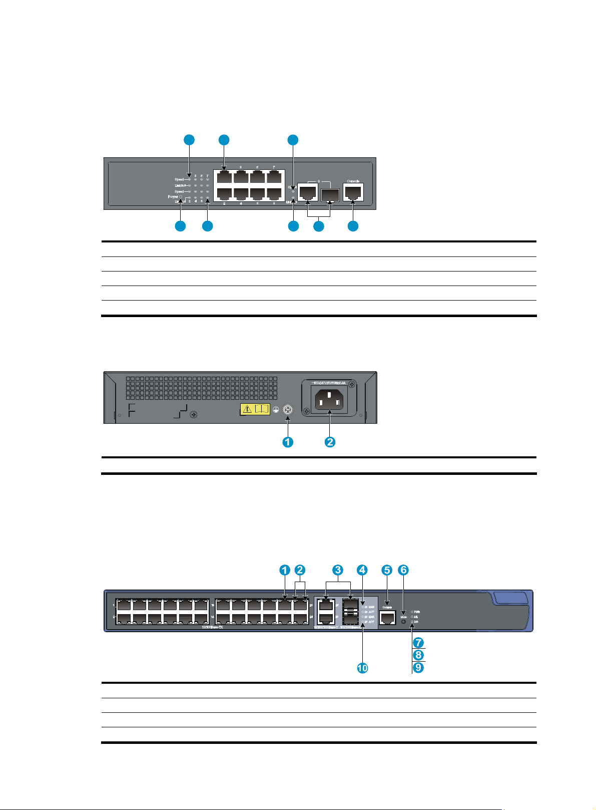
Figure 5 A3100-8 v2 SI/A3100-8 v2 EI front panel
1 2 3
(1) Speed LED for a 10/100Base-TX Ethernet port (2) 10/100Base-TX Ethernet ports
(3) Speed LED for a combo interface (4) Console port
(5) Combo interface (10/100/1000Base-T Ethernet port on the left, 100/1000Base-X SFP port on the right)
(6) Link/Act LED for a combo interface (7) Link/Act LED for a 10/100Base-TX Ethernet port
(8) Power LED
Rear panel
Figure 6 A3100-8 v2 SI/A3100-8 v2 EI rear panel
(1) Grounding screw (2) AC-input power receptacle
A3100-24-PoE v2 EI
678
5
4
Front panel
Figure 7 A3100-24-PoE v2 EI front panel
(1) 10/100Base-TX Ethernet port
(2) 10/100Base-TX Ethernet port LEDs (left: yellow, right: green)
(3) Combo interface (10/100/1000Base-T Ethernet port on the left, 100/1000Base-X SFP port on the right)
(4) LINK LED for a combo interface (5) Console port
3
Page 8
Rear panel
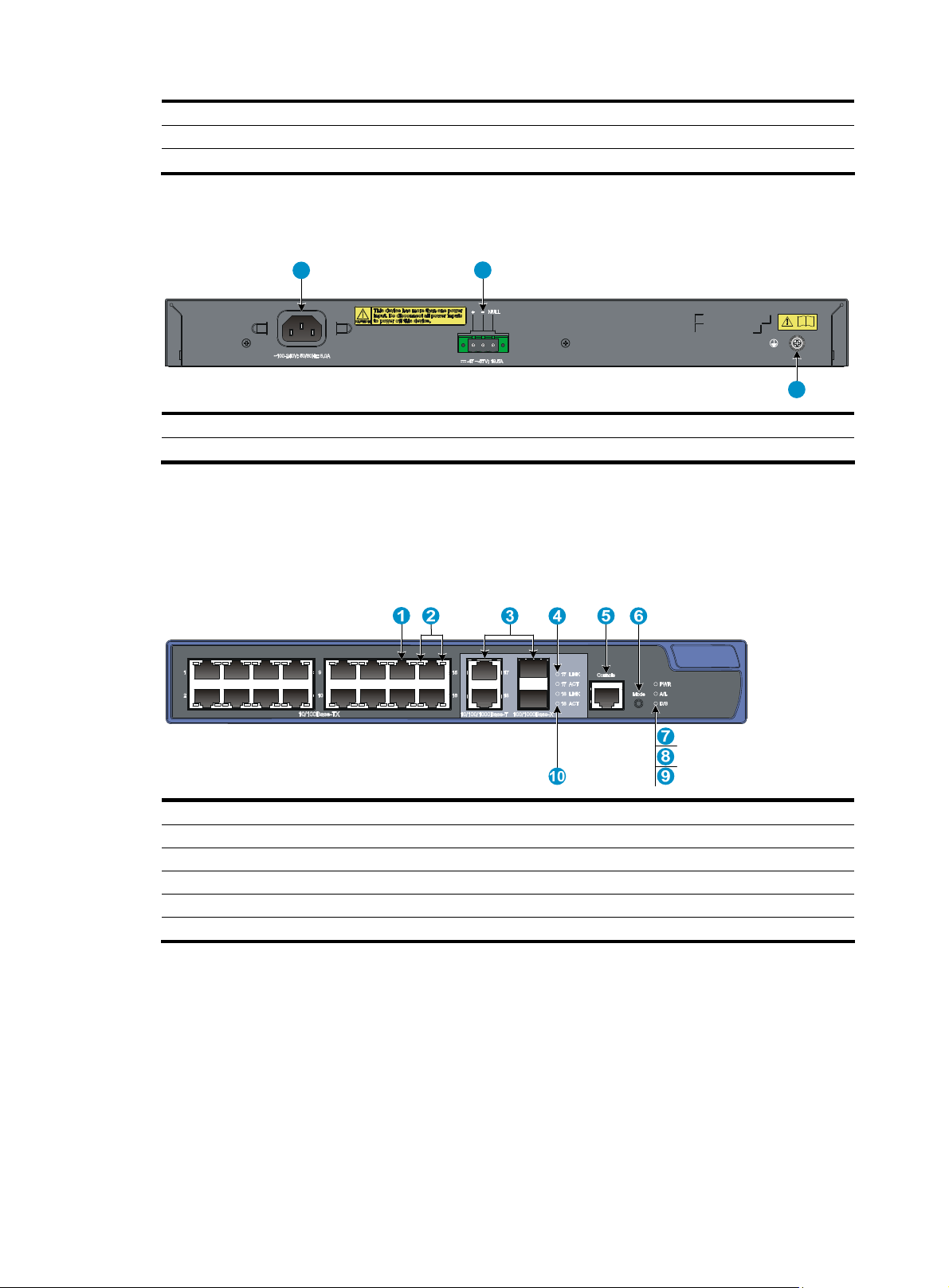
Figure 8 A3100-24-PoE v2 EI rear panel
(6) Port LED mode switching (Mode) button (7) Power (PWR) LED
(8) Port mode (A/L) LED (9) Port mode (D/S) LED
(10) ACT LED for a combo interface
1
(1) AC-input power receptacle (2) DC-input terminal block
(3) Grounding screw
A3100-16-PoE v2 EI
Front panel
Figure 9 A3100-16-PoE v2 EI front panel
2
3
(1) 10/100Base-TX Ethernet port (2) 10/100Base-TX Ethernet port LEDs (left: yellow, right: green)
(3) Combo interface (10/100/1000Base-T Ethernet port on the left, 100/1000Base-X SFP port on the right)
(4) LINK LED for a combo interface (5) Console port
(6) Port LED mode switching (Mode) button (7) Power (PWR) LED
(8) Port mode (A/L) LED (9) Port mode (D/S) LED
(10) ACT LED for a combo interface
4
Page 9
Rear panel
Figure 10 A3100-16-PoE v2 EI rear panel
(1) AC-input power receptacle (2) DC-input terminal block
(3) Grounding screw
A3100-8-PoE v2 EI
Front panel
Figure 11 A3100-8-PoE v2 EI front panel
Rear panel
Figure 12 A3100-8-PoE v2 EI rear panel
(1) 10/100Base-TX Ethernet port
(2) 10/100Base-TX Ethernet port LEDs (left: yellow, right: green)
(3) Combo interface (10/100/1000Base-T Ethernet port on the left, 100/1000Base-X SFP port on the right)
(4) LINK LED for a combo interface (5) Console port
(6) Port LED mode switching (Mode) button (7) Power (PWR) LED
(8) Port mode (A/L) LED (9) Port mode (D/S) LED
(10) ACT LED for a combo interface
(1) AC-input power receptacle (2) Grounding screw
5
Page 10

Right side panel
The A3100-8-PoE v2 EI switch has one security lock slot on the right-side panel to prevent theft. You must
purchase a cable lock separately.
Figure 13 A3100-8-PoE v2 EI left side panel
(1) Security lock slot
6
Page 11

Preparing for installation
Safety recommendations
To avoid any equipment damage or bodily injury caused by improper use, read the following safety
recommendations before installation. Note that the recommendations do not cover every possible
hazardous condition.
• Before cleaning the switch, unplug all power cords from the switch. Do not clean the switch with wet
cloth or liquid.
• Do not place the switch near water or in a damp environment. Prevent water or moisture from
entering the switch chassis.
• Make sure that the ground is dry and flat and anti-slip measures are in place.
• Do not place the switch on an unstable case or desk. The switch might be severely damaged in case
of a fall.
• Keep the chassis and installation tools away from walk areas.
• Do not wear loose clothing, jewelry (for example, necklace), or any other objects that could get
caught in the chassis when you install and maintain the switch.
• To avoid electrical shocks, do not open the chassis while the switch is operating or when the switch
is just powered off.
Examining the installation site
The A3100 v2 Switch Series must be used indoors. To ensure normal operation and long service life of
your switch, install it in an environment that meets the requirements described in the following
subsections.
Electricity safety
• Clear the work area of possible hazards, such as ungrounded power extension cables, missing
safety grounds, and wet floors.
• Make sure that the operating voltage is as required.
• Locate the emergency power-off switch in the room before installation. Shut the power off at once in
case accident occurs.
• Unplug all the external cables (including power cords) before moving the chassis.
• Always check that the power has been disconnected.
ESD prevention
To prevent the electronic components from being damaged by the electrostatic discharge (ESD), you
should not only take ESD measures where the switch is located, but also take the following precautions:
• Make sure the switch is well grounded. For how to ground the switch, see “Grounding the switch.”
• Always wear an ESD-preventive wrist strap when installing hot swappable modules.
7
Page 12
g
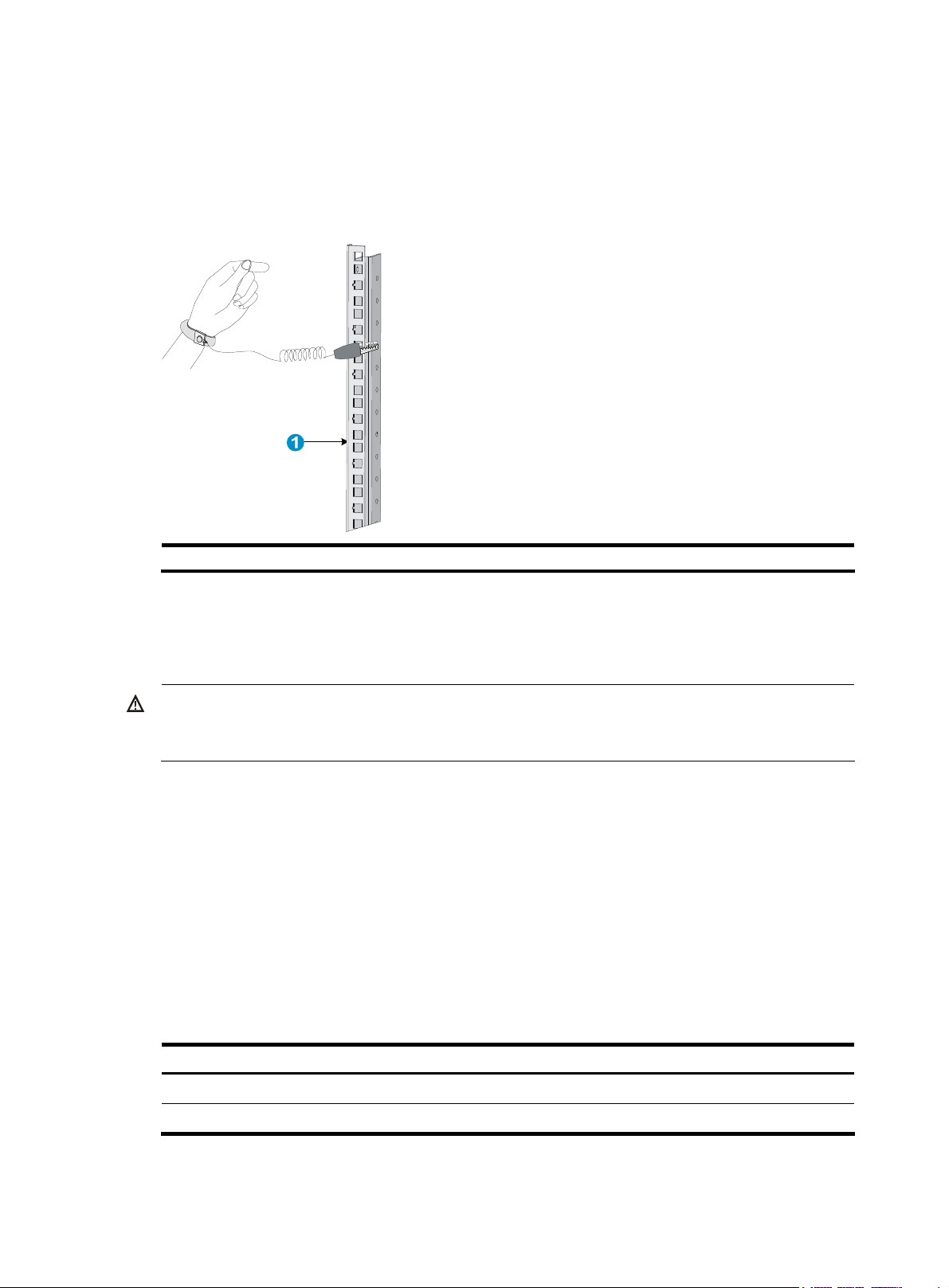
To use the ESD-preventive wrist strap:
1. Wear the wrist strap on your wrist.
2. Lock the wrist strap tight around your wrist to keep good contact with the skin.
3. Attach the ESD-preventive wrist strap to a post on the rack or ground it by using other methods.
Figure 14 Use an ESD-preventive wrist strap
(1) Rack post
Laser safety
The A3100 v2 switches are Class 1 laser devices.
WARNING!
Do not stare into any fiber port when the switch has power. The laser li
may hurt your eyes.
Temperature/humidity
Maintain appropriate temperature and humidity in the equipment room.
• Lasting high relative humidity can cause poor insulation, electricity creepage, mechanical property
change of materials, and metal corrosion.
• Lasting low relative humidity can cause washer contraction and ESD and bring problems including
loose captive screws and circuit failure.
• High temperature can accelerate the aging of insulation materials and significantly lower the
reliability and lifespan of the switch.
ht emitted from the optical fiber
Table 2 Temperature requirements
Temperature Range
Operating temperature 0°C to 45°C (32°F to 113°F)
Storage temperature –40°C to +70°C (–40°F to +158°F)
8
Page 13

CAUTION:
If condensation appears on the switch when you move it to a high-temperature environment, dry the switch
before powering it on to avoid short circuits.
Table 3 Humidity requirements
Humidity Range
Operating humidity (noncondensing) 10% to 95%
Storage humidity (noncondensing) 5% to 95%
Cleanness
Dust buildup on the chassis may result in electrostatic adsorption, which causes poor contact of metal
components and contact points, especially when indoor relative humidity is low. In the worst case,
electrostatic adsorption can cause communication failure.
Table 4 Dust concentration limit in the equipment room
Substance Concentration limit (particles/cu m)
EMI
Dust particles ≤ 3 x 10⁴ (no visible dust on the tabletop over three days)
NOTE:
Dust diameter ≥ 5 μm
The equipment room must also meet strict limits on salts, acids, and sulfides to eliminate corrosion and
premature aging of components, as shown in Table 5.
Table 5 Harmful gas limits in the equipment room
Gas Max. (mg/m
SO2 0.2
H2S 0.006
NH
3
Cl
2
0.05
0.01
3
)
All electromagnetic interference (EMI) sources, from outside or inside of the switch and application
system, adversely affect the switch in a conduction pattern of capacitance coupling, inductance coupling,
electromagnetic wave radiation, or common impedance (including the grounding system) coupling. To
prevent EMI, take the following actions:
• If AC power is used, use a single-phase three-wire power receptacle with protection earth (PE) to
filter interference from the power grid.
• Keep the switch far away from radio transmitting stations, radar stations, and high-frequency
devices.
• Use electromagnetic shielding, for example, shielded interface cables, when necessary.
9
Page 14
• Route interface cables only indoors to prevent signal ports from getting damaged by overvoltage or
overcurrent caused by lightning strikes.
Grounding
Using a good grounding system to protect your switch against lightning shocks, interferences, and ESD
is essential to the operating reliability of your switch. Make sure that the resistance between the chassis
and ground is less than 1.5 ohm. For more information about grounding the A3100 v2 Switch Series, see
“Grounding the switch.”
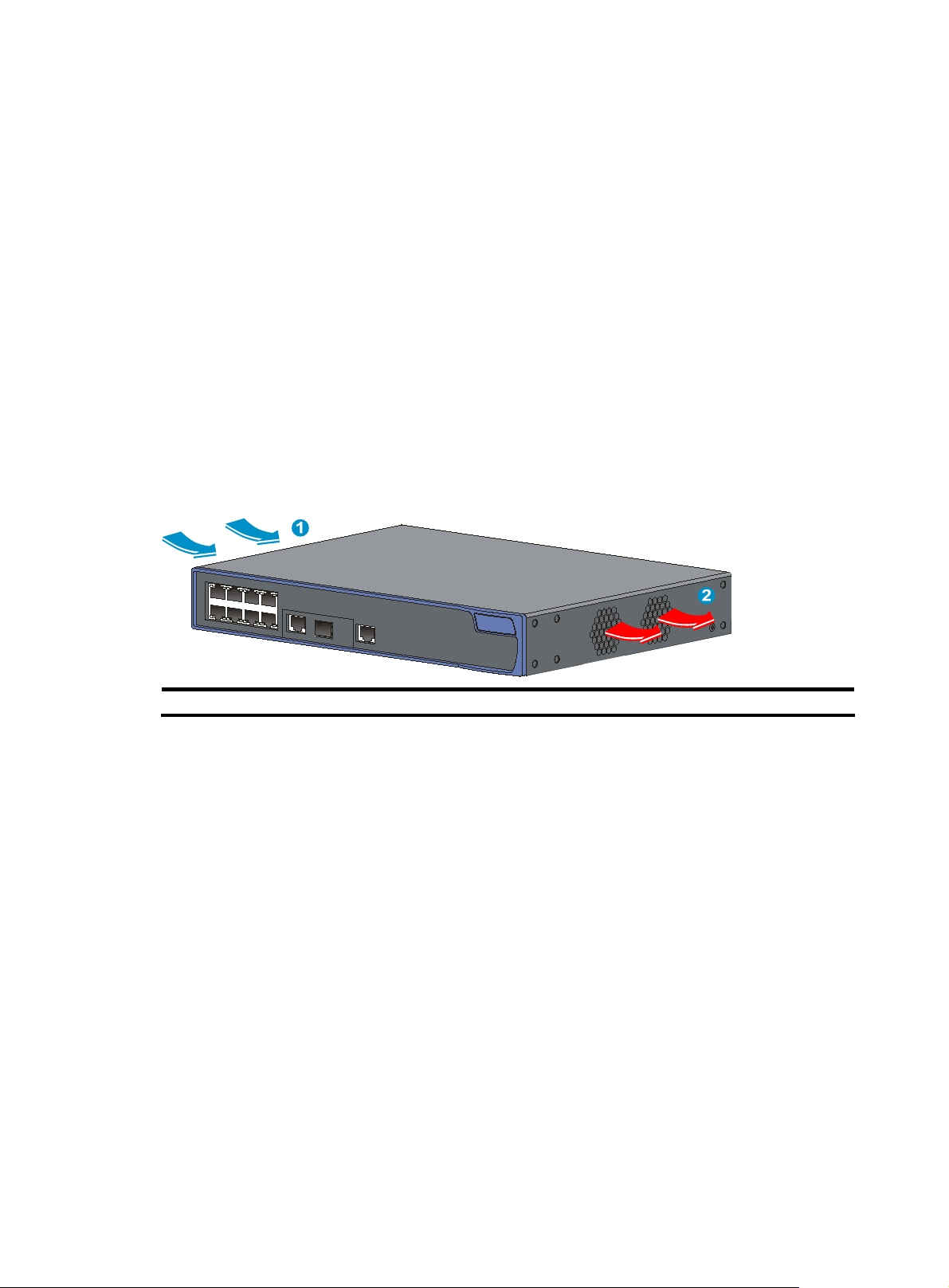
Cooling
The cooling system of the A3100 v2 Switch Series varies by the switch model:
• Non PoE switches (fanless): There are openings on the left, right, and rear of the switch for natural
heat dissipation.
• PoE switches (built-in fans): Fans blow air from the left to the right of the chassis for heat dissipation.
See Figure 15.
Figure 15 Airflow through a PoE switch
For adequate heat dissipation, plan the installation site according to the airflow of your switch, and
adhere to the following requirements:
• Leave a clearance of at least 10 cm (3.94 in) around the air intake and exhaust vents.
• Consider the heat dissipation of the installation site when determining air-conditioning
• Make sure the hot air generated by equipment at the bottom of the rack is not drawn in the intake
• The installation site has a good cooling system.
Space
For adequate ventilation and ease of maintenance, adhere to the following requirements:
• The clearance between the rack and walls or other devices is at least 1 m (3.28 ft).
• The headroom in the equipment room is no less than 3 m (9.84 ft).
(1) Air intake (2) Air exhaust
requirements to ensure that cool air can enter the switch.
of the equipment above.
10
Page 15

Installation tools
Table 6 Tool list
Category Tool
Measuring and marking tools Long tape, ruler of 1 m (3.28 ft), gradienter, marker, chalk line, and pencil
Drills Percussion drill, electric drill, and several auxiliary drill bits
Fastening tools
Flat-blade screwdriver P4-75 mm
Phillips screwdriver P1-100 mm, P2-150 mm, and P3-250 mm
Socket wrench M5
Socket wrench M6
Small tools
Auxiliary tools
Tools for fiber-optic cleaning Lint-free paper and optical fiber microscope
Equipment
Needle-nose pliers, diagonal pliers, combination pliers, wire-stripping pliers,
crimping pliers, RJ-45 crimping pliers
ESD-preventive wrist strap, hair brush, tweezers, paper knife, hand bellows,
electric iron, solder wire, ladder, cable stripper, vacuum cleaner, crowbar,
rubber hammer, and blower
Multimeter, 500 V Megohmmeter for measuring the insulation resistance,
error detector, optical power meter, and earth resistance tester
NOTE:
Tools and equipment are not supplied with the switch. Prepare them yourself as needed.
11
Page 16
g
Installing the switch
CAUTION:
Keep the tamper-proof seal on a mountin
chassis, contact the local agent of HP for permission. Otherwise, HP shall not be liable for any
consequence caused thereby.
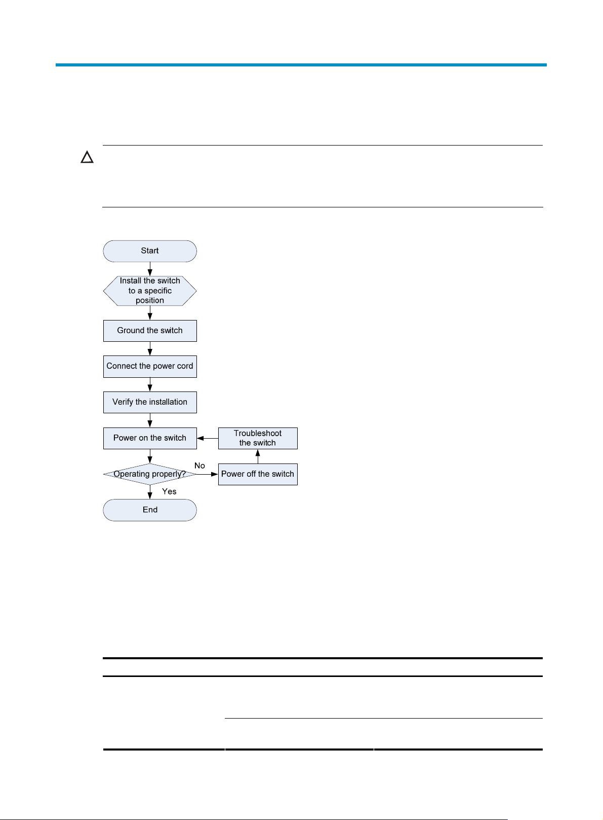
Figure 16 Hardware installation flow
screw on the chassis cover intact, and if you want to open the
Installing the switch
Selecting an installation method
The A3100 v2 Switch Series supports multiple installation methods. You can select one as needed.
Table 7 A3100 v2 Switch Series installation methods
Switch model Installation methods Installation accessories
• Installing the switch into the
A3100-24 v2 SI
A3100-24 v2 EI
19- i n c h r a c k (Rack mounting by
using front mounting brackets)
• Mounting the switch on a
workbench
12
Front mounting bracket. See callout A in
Figure 17 (supplied with the switch).
Rubber pad: See Figure 19 (supplied
with the switch).
Page 17

Switch model Installation methods Installation accessories
A3100-16 v2 SI
A3100-16 v2 EI
A3100-8 v2 SI
A3100-8 v2 EI
A3100-24-PoE v2 EI
A3100-16-PoE v2 EI
A3100-8-PoE v2 EI
•
Installing the switch into the
19- i n c h r a c k (Rack mounting by
using front mounting brackets)
• Mounting the switch on a
workbench
• Installing the switch into the
19- i n c h r a c k (Rack mounting by
using front mounting brackets)
• Mounting the switch on a
workbench
• Installing the switch into the
19- i n c h r a c k (Rack mounting by
using front and rear mounting
brackets)
• Mounting the switch on a
workbench
• Installing the switch into the
19- i n c h r a c k (Rack mounting by
using front mounting brackets)
• Mounting the switch on a
workbench
Front mounting bracket: HP A3100-16
Rack Mount Kit (JD321A).
See callout C in Figure 17 (optional).
Rubber pad: See Figure 19 (supplied
with the switch).
Front mounting bracket: HP A3100-8
Rack Mount Kit (JD322A).
See callout B in Figure 17 (optional).
Rubber pad: See Figure 19 (supplied
with the switch).
Front mounting bracket. See callout A in
Figure 17 (supplied with the switch).
Rear mounting bracket: See Figure 18
(supplied with the switch).
Rubber pad: See Figure 19 (supplied
with the switch).
Front mounting bracket: HP
A3100-16-PoE and 8-PoE Rack Mount
Kit (JD323A).
See callout D in Figure 17 (optional).
Rubber pad: See Figure 19 (supplied
with the switch).
Installation accessories
Mounting brackets for rack mounting
The A3100 v2 Switch Series provides different mounting brackets for different models. Select them as
required.
13
Page 18
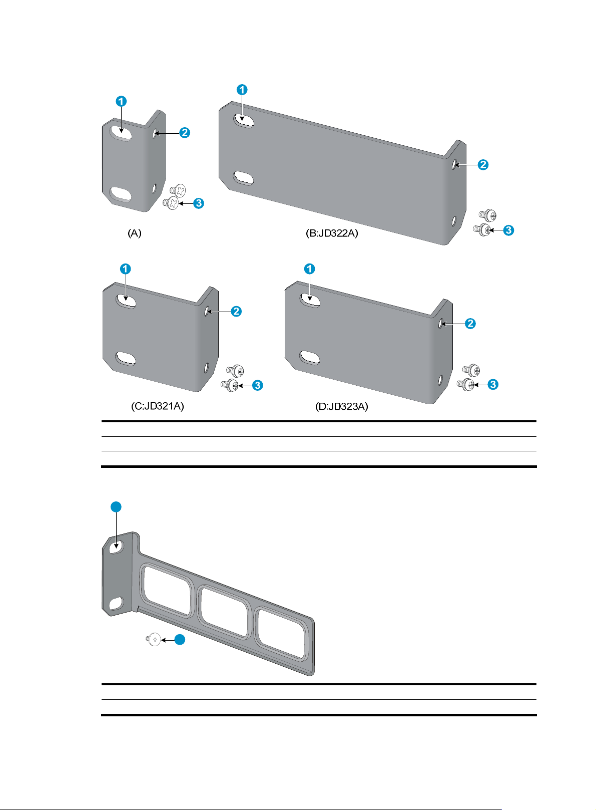
Figure 17 Front mounting brackets
(1) Screw hole (for M6 screw) for fixing the front mounting bracket to the rack
(2) Screw hole for fixing the front mounting bracket to the switch
(3) M4 screws for fixing the front mounting bracket to the switch
Figure 18 Rear mounting bracket
1
2
(1) Screw hole (for M6 screw) for fixing the rear mounting bracket to the rack
(2) Load-bearing screw (installed to the switch)
14
Page 19
g
t
g
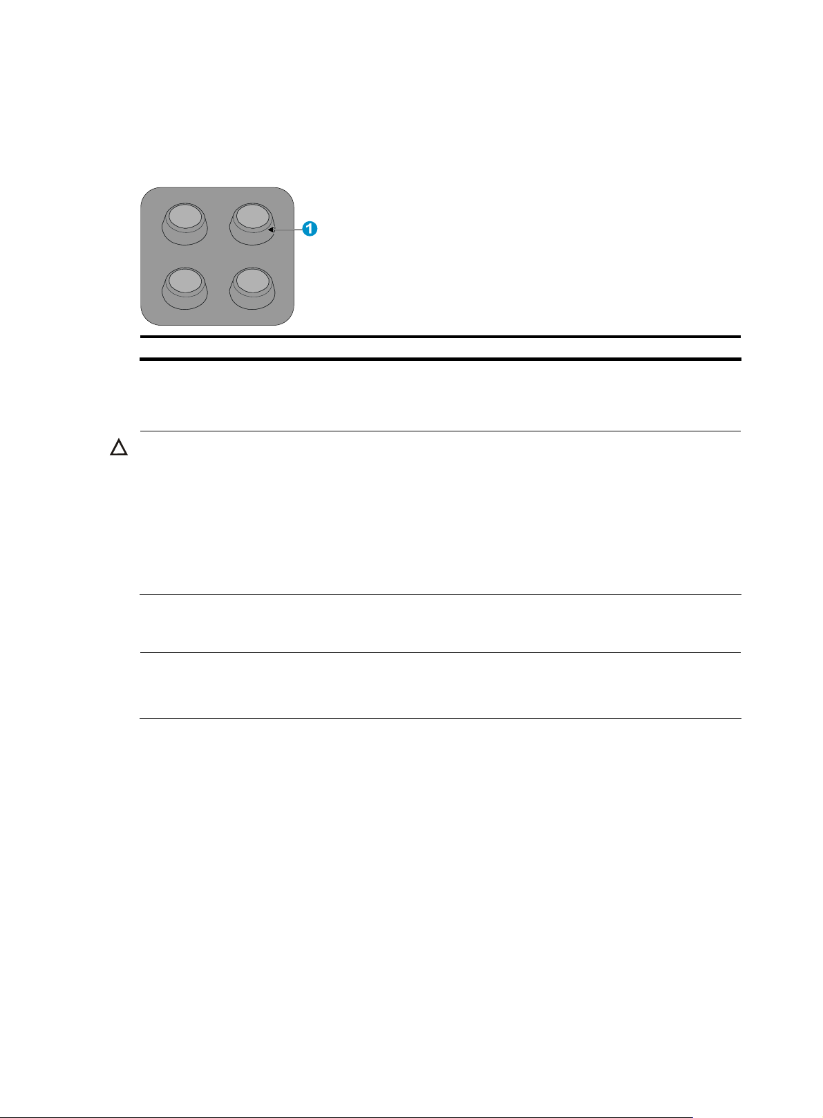
Rubber pads
Each A3100 v2 switch provides four rubber pads, as shown in Figure 19. Before mounting the switch to
a workbench, attach the four rubber pads to the switch bottom first.
Figure 19 Rubber pad appearance
(1) Rubber pad
Installing the switch into the 19-inch rack
CAUTION:
• Ensure a clearance of 1U (44.45 mm, or 1.75 in) between equipment for heat dissipation.
• For a switch with a depth greater than 300 mm (11.81 in), the front mounting brackets only secure the
switch rather than bear its weight. To mount this switch to a rack, you need to use front mounting
brackets and other accessories. For example, use front mountin
(for more information, see “Rack mounting by using front and rear mounting brackets.”), or use fron
mounting brackets and a rack shelf (if there is a rack shelf on the rack, put the switch on the rack shelf,
move the switch to an appropriate position, and fix the switch by using front mounting brackets.).
Rack mounting by using front mounting brackets
NOTE:
The installation procedures for front mountin
front mounting brackets supplied with the switch as an example.
To install the switch to the rack by using front mounting brackets:
1. Wear an ESD-preventive wrist strap and make sure it makes good skin contact and is well
grounded, check that the rack is sturdy and well grounded.
brackets with different length are similar. The following uses
brackets and rear mounting brackets
2. Unpack the screws (packed with the front mounting brackets), and install the front mounting
brackets to the switch with the screws. See Figure 20.
15
Page 20

Figure 20 Install the front mounting brackets
(1) Chassis front panel
3. Determine where to install the switch in the rack, and install the cage nuts to the corresponding
positions on the front rack posts.
4. Supporting the bottom of the switch, move the switch to the appropriate position. Have another
person to install the mounting brackets to the rack posts with the M6 screws. See Figure 21.
Figure 21 Mount the switch to the rack by using front mounting brackets
(1) Front rack posts (2) Chassis front panel (3) Front mounting bracket
Rack mounting by using front and rear mounting brackets
To mount the switch to the rack by using front and rear mounting brackets:
1. Wear an ESD-preventive wrist strap and make sure it makes good skin contact and is well
grounded.
16
Page 21

g
g
2. Check that the rack is sturdy and well grounded.
3. Unpack the screws (packed with the front mounting brackets), and install the front mounting
brackets to the switch with the screws. See Figure 20.
4. Unpack the load-bearing screws (packed with the rear mounting brackets), and install them to the
appropriate positions on the two sides of the switch. See Figure 22.
Figure 22 Rack mounting by using front and rear mounting brackets
2
1
3
4
5
(1) Load-bearing screw
(2) Load-bearing screw positions (select one as needed)
(3) Chassis front panel (4) Front mounting bracket
(5) Screw (packaged with the front mounting bracket) for fixing the front mounting bracket to the switch
NOTE:
The switch provides three positions on both sides to mount a load-bearin
screw. Select a proper position
according to the actual requirements. The rear mounting brackets support the switch by the load-bearin
screws.
5. Determine where to install the switch to the rack, and install the cage nuts to the corresponding
positions on the front and rear rack posts.
6. Fix the rear mounting brackets to the rear rack posts by using the M6 screws. See Figure 23.
17
Page 22

Figure 23 Mount the switch to the rack by using rear mounting brackets
1
1
2
(1) Rack posts (2) Rear mounting bracket
CAUTION:
Make sure the thinner edge of the rear mounting bracket faces upwards to ensure that the mounting
bracket can make close contact with the load-bearing screws.
7. Supporting the switch bottom with one hand, use the other hand to push the switch into the rack
until the load-bearing screws on the switch make close contact with the upper edge of the rear
mounting bracket. See Figure 24.
18
Page 23

Figure 24 Mount the switch to the rack by using front and rear mounting brackets
(1) Chassis rear panel (2) Rear rack post
(3) Load-bearing screw (4) Rear mounting bracket
8. Have another person to fix the front mounting brackets to the front rack posts by using the M6
screws, making sure that the front and rear mounting brackets can fix the switch steadily into the
rack. See Figure 25.
19
Page 24

Figure 25 Mount the switch to the rack by using front and rear mounting brackets
1 2
3
4
5
6
(1) Load-bearing screw (2) Rear mounting bracket
(3) Chassis front panel (4) M6 screw for fix the front mounting bracket to the rack
(5) Front mounting bracket (6) Front rack post
Mounting the switch on a workbench
To mount the switch on a workbench:
1. Check that the workbench is sturdy and well grounded.
2. Place the switch with bottom up, and clean the round holes in the chassis bottom with dry cloth.
3. Attach the rubber feet to the four round holes in the chassis bottom.
4. Place the switch with upside up on the workbench.
IMPORTANT:
• Ensure good ventilation and 10 cm (3.94 in) of clearance around the chassis for heat dissipation.
• Avoid placing heavy objects on the switch.
• Non PoE switches are fanless. Install them in an environment with good ventilation. To stack switches one
on another, keep at least a vertical distance of 1.5 cm (0.59 in) between equipment.
20
Page 25

g
Grounding the switch
WARNING!
Correctly connecting the switch grounding cable is crucial to lightning protection and EMI protection.
NOTE:
The power and grounding terminals in this section are for illustration only.
The power input end of the switch has a noise filter, whose central ground is directly connected to the
chassis to form the chassis ground (commonly known as PGND). You must securely connect this chassis
ground to the earth so the faradism and leakage electricity can be safely released to the earth to
minimize EMI susceptibility of the switch.
You can ground the switch in one of the following ways, depending on the grounding conditions
available at the installation site:
• Grounding the switch with a grounding strip
• Grounding the switch with a grounding conductor buried in the earth ground
• Grounding the switch by using the AC power cord
Grounding cable
The A3100 v2 Switch Series is provided with a yellow-green grounding cable. One end of the cable has
an OT terminal, and the other end is naked and soldered. See Figure 26.
Figure 26 Grounding cable
(1) OT terminal of the grounding cable
Grounding the switch with a grounding strip
If a grounding strip is available at the installation site, connect the grounding cable to the grounding
strip.
WARNING!
Connect the grounding cable to the
main or lightning rod.
rounding system in the equipment room. Do not connect it to a fire
NOTE:
The grounding cable supplied with the A3100 v2 Switch Series does not have an auxiliary OT terminal.
Connecting the grounding cable to the switch
To connect the grounding cable to the switch:
21
Page 26

1. Remove the grounding screw from the rear panel of the switch chassis.
2. Attach the grounding screw to the OT terminal of the grounding cable.
3. Use a screwdriver to fasten the grounding screw into the grounding screw hole.
Figure 27 Connect the grounding cable to the grounding hole of the switch
(1) Chassis rear panel (2) Grounding sign
(3) Grounding hole (4) OT terminal
(5) Grounding cable (6) Grounding screw
Connecting the grounding cable to a grounding strip
To connect the grounding cable to a grounding strip:
1. Remove the hex nut of a grounding post on the grounding strip.
2. Cut the grounding cable as appropriate for connecting to the grounding strip.
3. Make the connector on the grounding cable:
{ If you have an OT terminal, follow callout A in Figure 28 to make the connector: Peel 5 mm
(0.20 in) of insulation sheath by using a wire stripper, and insert the bare metal part through the
black insulation covering into the end of the OT terminal. Secure the metal part of the cable to
the OT terminal with a crimper, cover the joint with the insulation covering, and heat the
insulation covering with a blow dryer to completely cover the metal part.
{ If you do not have an OT terminal, follow callout B in Figure 28 to make the connector: Peel the
insulation sheath by an appropriate length with a wire stripper, and then bend the naked metal
part.
4. Connect the connector to the grounding strip, and fasten it with the removed hex nut. See Figure
29.
22
Page 27

Figure 28 Make the grounding cable connector
Figure 29 Connect the grounding cable to a grounding strip
(1) Grounding post (2) Grounding strip
(3) Grounding cable (4) Hex nut
Grounding the switch with a grounding conductor buried in the earth ground
If the installation site has no grounding strips, but earth ground is available, hammer a 0.5 m (1.64 ft) or
longer angle iron or steel tube into the earth ground to serve as a grounding conductor.
The dimensions of the angle iron must be at least 50 × 50 × 5 mm (1.97 × 1.97 × 0.20 in). The steel tube
must be zinc-coated and its wall thickness must be at least 3.5 mm (0.14 in).
Weld the yellow-green grounding cable to the angel iron or steel tube and treat the joint for corrosion
protection.
23
Page 28

t
Figure 30 Ground the switch by burying the grounding conductor into the earth
(1) Grounding screw (2) Grounding cable (3) Earth
(4) Joint (5) Grounding conductor (6) Chassis rear panel
Grounding the switch by using the AC power cord
If the installation site has no grounding strips, you can ground an AC-powered switch through the
protective earth (PE) wire of the power cord, but must make sure:
• The power cord has a PE terminal.
• The ground contact in the power outlet is securely connected to the ground in the power distribution
room or on the AC transformer side.
• The power cord is securely connected to the power outlet.
NOTE:
If the ground contact in the power outlet is not connected to the ground, report the problem and reconstruc
the grounding system.
Figure 31 Ground through the PE wire of the AC power cord
(1) Three-wire AC power cord (2) Chassis rear panel
Connecting the power cord
24
Page 29

CAUTION:
Before powering on the switch, you must connect the power cord and make sure the switch is well
grounded.
Connecting an AC power cord to the switch
To connect the AC power cord:
1. Wear an ESD-preventive wrist strap, and make sure the wrist strap makes good skin contact and
is well grounded.
2. Connect one end of the AC power cord to the AC-input power receptacle on the switch (see Figure
32).
3. Connect the other end of the power cord to the AC power outlet.
4. Check the power LED (Power/PWR) on the front panel. If the LED is on, the power cord is properly
connected.
Figure 32 Connect the AC power cord (I)
Connecting the DC power cord
The A3100-24-PoE v2 EI provides a DC power receptacle as shown in Figure 33. You can use the –48
VDC power in the equipment room or the HP RPS DC power input.
Figure 33 DC power receptacle
+: Chassis ground —: Input voltage range (–47 VDC to –57 VDC) NULL: Reserved
To connect the DC power cord:
1. Wear an ESD-preventive wrist strap and make sure it makes good skin contact and is well
grounded.
25
Page 30

2. Unpack the DC power cord, correctly orient the plug at one end of the cable with the power
receptacle on the power supply, and insert the plug into the power receptacle (see callout 1 in
Figure 34).
Figure 34 Connect the DC power cord
2
2
3. Tighten the screws on the plug with a flat-blade screwdriver to secure the plug in the power
receptacle (see callout 2 in Figure 34).
4. Connect the two wires at the other end of the power cord to a –48 VDC power source.
5. Check the power LED (PWR) on the front panel. If the LED is on, the power cord is properly
connected.
CAUTION:
The length of a DC power cord must be shorter than 3 m (9.84 ft).
Verifying the installation
After you complete the installation, verify that:
• The grounding cable is securely connected.
• The selected power supply matches that required by the switch.
• The power cords are properly connected.
1
26
Page 31

Accessing the switch for the first time
Setting up the configuration environment
The first time you access the switch you must use a console cable to connect a console terminal, for
example, a PC, to the console port on the switch.
Figure 35 Connect the console port to a terminal
Connecting the console cable
Console cable
A console cable is an 8-core shielded cable, with a crimped RJ-45 connector at one end for connecting
to the console port of the switch, and a DB-9 female connector at the other end for connecting to the
serial port on the console terminal.
Figure 36 Console cable
A side
Pos.9
A
Pos.1
Main label
8
1
B side
B
Connection procedure
To connect a terminal, for example, a PC, to the switch:
27
Page 32

1. Plug the DB-9 female connector of the console cable to the serial port of the PC.
2. Connect the RJ-45 connector to the console port of the switch.
NOTE:
Identify the mark on the console port and make sure that you are connecting to the correct port.
The serial ports on PCs do not support hot swapping. If the switch has been powered on, connect the console cable
to the PC before connecting to the switch, and when you disconnect the cable, first disconnect from the switch.
Setting terminal parameters
To configure and manage the switch, you must run a terminal emulator program on the console terminal.
The following are the required terminal settings:
• Bits per second—9,600
• Data bits—8
• Parity—None
• Stop bits—1
• Flow control—None
• Emulation—VT100
To set terminal parameters, for example, on a Windows XP HyperTerminal:
1. Select Start > All Programs > Accessories > Communications > HyperTerminal.
The Connection Description dialog box appears.
2. Enter the name of the new connection in the Name field and click OK.
Figure 37 Connection description
3. Select the serial port to be used from the Connect using list, and click OK.
28
Page 33

Figure 38 Set the serial port used by the HyperTerminal connection
4. Set Bits per second to 9600, Data bits to 8, Parity to None, Stop bits to 1, and Flow control to None,
and click OK.
Figure 39 Set the serial port parameters
5. Select File > Properties in the HyperTerminal window.
29
Page 34

Figure 40 HyperTerminal window
6. On the Settings tab, set the emulation to VT100 and click OK.
Figure 41 Set terminal emulation in Switch Properties dialog box
30
Page 35

g
Powering on the switch
Verification before power-on
Before powering on the switch, verify that:
• The power cord is properly connected.
• The input power voltage meets the requirement of the switch.
The console cable is properly connected, the terminal or PC used for configuration has started, and the
configuration parameters have been set.
Powering on the switch
Power on the switch, and you can see the following information.
CAUTION:
• If you lo
displayed, and you will enter the command line interface (CLI).
• The output information varies depending on the software version.
Starting......
************************************************************************
* *
* HP A3100-24-PoE v2 EI Switch BOOTROM, Version 109 *
* *
************************************************************************
Copyright (c) 2010-2011 Hewlett-Packard Development Company, L.P.
Creation Date : Apr 12 2011,11:13:54
CPU Clock Speed : 200MHz
Memory Size : 128MB
Flash Size : 16MB
CPLD Version : 003
PCB Version : Ver.A
Mac Address : 000FE23060C1
Press Ctrl-B to enter Extended Boot menu...0
Starting to get the main application file--flash:/a3100 ei.bin!..............
...............................................
The main application file is self-decompressing................................
...............................................................................
...............................................................................
...............................................................................
......Done!
System is starting...
User interface aux0 is available.
in to the switch through the console port after powering on the switch, no boot information is
31
Page 36

Press ENTER to get started.
Press Enter at the prompt, and you can configure the switch when the prompt <HP> appears.
For more information about initial switch configuration, see “Initially configuring the switch.”
Initially configuring the switch
By default, the administrator can only log in to the switch through the console port without any
authentication. The default login method does not facilitate remote maintenance and management of the
switch, and brings vulnerabilities to the switch. After the first login, you can perform the following
configurations.
• Configure the login method so that you can remotely maintain and manage the switch and control
login user privileges.
• Configure the access function of the switch to satisfy the requirements of different users.
Configuring a login authentication method
By configuring the authentication mode and the corresponding username, authentication method, and
user privilege level, you can perform login user privilege control, and improve switch security.
The switch supports login through the console port, telnet, SSH, and NMS.
The following section takes login through telnet for example. Login through telnet supports three login
authentication methods.
Table 8 Telnet login authentication methods
Authentication method Feature Application scenarios
None
Password
Username and password
Easy to configure, allows any
user to Telnet to your switch, and
lowest in security
Easy to configure, allows any
user knowing the password to
telnet to your switch, high in
security, but incapable of
assigning different privilege
levels to different users
Complex to configure, allows
users inputting the correct
username and password to
Telnet to your switch, high in
security, and capable of
assigning different privilege
levels to different users
Lab environments and extremely secure
network environments
Environments that do not need granular
privilege management
Environments where multiple operators
cooperate to manage the switch
32
Page 37

Configuring the basic access function
When the switch with the default settings accesses the network, it can perform basic data transmission.
To implement more service requirements, you can configure the basic access function on the switch.
Table 9 Basic access function configurations
Function Description
IP addresses Allows you to remotely manage the switch and use the switch in a network.
Static routing Allows the switch to implement routing.
VLAN Divides the network into multiple VLANs, and improves data security.
MSTP Avoids loops in a network using dual uplinks to provide redundancy.
NOTE:
For more information about login methods and access function configuration, see
Series Configuration Guides
.
HP A3100 v2 Switch
33
Page 38

g
Connecting the switch to the network
NOTE:
HP recommends that you perform basic confi
uration for your switch before connecting it to the network.
Connecting your switch to the network through twisted pair cables
The 10/100/1000Base-T ports of the A3100 v2 Switch Series use RJ-45 connectors and support
MDI/MDI-X auto-sensing. Use category-5 or higher twisted pair cables to connect the Ethernet ports of
your switch to the network.
To connect your switch to the network through twisted pair cables:
1. Make a straight-through or crossover Ethernet cable as needed.
2. Plug one end of the twisted pair cable into the RJ-45 Ethernet port of your switch.
3. Plug the other end of the twisted pair cable into the RJ-45 Ethernet port of the access device in the
network.
4. Check whether the LEDs of the RJ-45 Ethernet port are normal.
NOTE:
For more information about twisted pair cables, see the chapter “Appendix C Ethernet twisted pair cable.”
IMPORTANT:
• After connecting the switch to the network, you can use the ping or tracert command to check the
interoperability between the switch and the network. For more information, see
Series Command References
• If the port status LED on the switch flashes after you connect the switch to the network, and the switch
does not respond to your commands, the switch may be sending or receiving broadcasts. In this case,
disconnect the switch to the network, re-configure the switch, and connect the switch to the network
again.
.
HP A3100 v2 Switch
Connecting your switch to the network through optical fibers
Figure 42 Connect the switch to the network through an optical fiber
34
Page 39

g
Installing an SFP transceiver module
NOTE:
This section only briefly describes the installation and operation
For more information, see
To install an SFP transceiver module:
1. Wear an ESD-preventive wrist strap and make sure it makes good skin contact and is well
grounded.
2. Unpack the SFP transceiver module. Do not touch the golden finger of the module.
3. Pivot the clasp of the transceiver module up so that it catches a knob on the top of the module.
4. Squeezing both sides of the module, gently push the module into the slot until it has firm contact
with the slot (you can feel that the top and bottom spring tabs catch in the slot). See Figure 43.
Figure 43 Install an SFP transceiver module
Pluggable SFP/SFP+/XFP Transceiver Modules Installation Guide
uidelines for an SFP transceiver module.
.
CAUTION:
• Do not remove the dust plug on the SFP transceiver module before installing it.
• Remove the fibers, if any, from the SFP transceiver module before installing it.
Connecting an optical fiber connector to an SFP transceiver module
NOTE:
For more information about optical fibers and fiber connectors, see
Modules User Guide
.
The SFP transceiver modules of the A3100 v2 Switch Series use LC connectors. See Figure 44.
HP A-Series Switches Transceiver
35
Page 40

g
g
Figure 44 Appearance of an LC connector
To connect your switch to the network through optical fibers:
1. Remove the dust cover of the optical fiber connector, and clean the end of the optical fiber.
2. Take off the dust plug of the SFP transceiver module, plug one end of the optical fiber into the
transceiver module in the switch, and plug the other end into the transceiver module in the access
device. See Figure 45.
3. Check that the LEDs of the optical interfaces are normal.
WARNING!
To avoid injury to your eyes, do not stare at the optical interfaces and optical fiber connectors when
connecting optical fibers.
Figure 45 Use the LC optical fiber connector to connect a transceiver module
LC plug
SFP module
IMPORTANT:
• Each SFP port is a member port of a combo interface. After connectin
the switch to the network through
the SFP port, you must use the combo enable fiber command to activate the SFP port.
• After connecting the switch to the network, you can use the ping or tracert command to check the
interoperability between the switch and the network. For more information, see
Series Command References
.
HP A3100 v2 Switch
• If the port status LED on the switch flashes after you connect the switch to the network, and the switch
does not respond to your commands, the switch may be sendin
or receiving broadcasts. In this case,
disconnect the switch to the network, re-configure the switch, and connect the switch to the network
again.
36
Page 41

g
Troubleshooting
TIP:
Clean your switch periodically because the noncompliant operatin
switch failures. At the same time, check the installation environments against the requirements in
“Preparing for installation.” Make sure the switch operates in a proper environment. Additionally,
periodically perform the power-on test for the spare switches.
Configuration terminal problems
If the configuration environment setup is correct, the configuration terminal displays booting information
when the switch is powered on. If the setup is incorrect, the configuration terminal displays nothing or
garbled text.
No terminal display
environments of switches may cause
If the configuration terminal displays nothing when the switch is powered on, verify the following items:
• The power supply is supplying power to the switch.
• The console cable is properly connected.
• The console cable has no problem and the terminal settings are correct.
Garbled terminal display
If terminal display is garbled, check that the following settings are configured for the terminal, for
example, HyperTerminal:
• Baud rate—9,600
• Data bits—8
• Parity—none
• Stop bits—1
• Flow control—none
• Emulation—VT100
Power supply failure
The PWR/Power LED on the front panel shows whether the power supply system of the switch operates
properly. The PWR/Power LED is steady green when the power supply system operates properly, and off
when the power supply system fails.
To troubleshoot the power supply failure:
1. Check the power cable connections. If a power cable is loose, re-plug the power cable. If a power
cable is broken, replace it.
2. Check the power supply system. Make sure that the power supply system works properly and
outputs a voltage required by the switch.
37
Page 42

g
Interface failure
Each interface has a corresponding LED. When an interface connected to the network works properly,
the corresponding LINK LED is on. If the LED of an interface connected to the network is off, the interface
or the connecting cable may fail.
To troubleshoot the interface:
1. Check whether the switch works properly.
2. Check the cable connection of the interface. For how to correctly connect the cable to an Ethernet
interface with a RJ-45 connector or an optical interface, see the chapter “Connecting the switch to
the network.”
3. Check whether the cable fails. Use the cable to connect two interfaces of the same type that work
properly. If the LEDs of the two interfaces are on, the cable is normal. Otherwise, the cable fails.
4. If the interface uses a transceiver module, check that the interface type is compatible with the
transceiver module and the transceiver module is compatible with the cable.
5. If the interface uses a transceiver module, make sure that the current transceiver module works
properly by replacing a normal transceiver module.
6. If the interface is a combo interface (which comprises a copper port and a fiber port), make sure
that the interface used for connecting is activated for the combo interface. Then, use the combo
enable { copper | fiber } command in interface view to activate the port, and check the LED.
NOTE:
• Each combo interface has one fiber SFP port and one copper Ethernet port. These two ports share one
port name and port view and cannot work simultaneously. When you activate one port (by using the
combo enable { copper | fiber } command), the other port automatically shuts down.
• After an interface fails, if the switch has an idle interface of the same type, you can plu
the idle interface.
7. Check that the speed and duplex settings of the interfaces of a link are the same. Make sure that
two interfaces can work together.
PoE system failure
If a PoE-capable switch cannot supply power to a powered device (PD) attached to the switch, follow
these steps to troubleshoot the PoE system:
1. Check that the power cable that connects the switch to the PD is a straight-through cable.
2. Make sure that the PoE-related configurations are correct. For how to configure PoE, see the
related configuration guide.
3. Check the temperature of the switch. The PoE-capable switch provides the overtemperature
protection mechanism. When the internal temperature of the switch exceeds 65°C (149°F), the
switch performs self protection and disables PoE on all ports. When the internal temperature drops
below 60°C (140°F), the switch enables PoE on all ports.
the cable into
38
Page 43

Support and other resources
Contacting HP
For worldwide technical support information, see the HP support website:
http://www.hp.com/support
Before contacting HP, collect the following information:
• Product model names and numbers
• Technical support registration number (if applicable)
• Product serial numbers
• Error messages
• Operating system type and revision level
• Detailed questions
Subscription service
HP recommends that you register your product at the Subscriber's Choice for Business website:
http://www.hp.com/go/wwalerts
After registering, you will receive email notification of product enhancements, new driver versions,
firmware updates, and other product resources.
Related information
Documents
To find related documents, browse to the Manuals page of the HP Business Support Center website:
http://www.hp.com/support/manuals
• For related documentation, navigate to the Networking section, and select a networking category.
• For a complete list of acronyms and their definitions, see HP A-Series Acronyms.
Websites
• HP.com http://www.hp.com
• HP Networking http://www.hp.com/go/networking
• HP manuals http://www.hp.com/support/manuals
• HP download drivers and software http://www.hp.com/support/downloads
• HP software depot http://www.software.hp.com
• HP Education http://www.hp.com/learn
39
Page 44

Conventions
This section describes the conventions used in this documentation set.
Command conventions
Convention Description
Boldface Bold text represents commands and keywords that you enter literally as shown.
Italic Italic text represents arguments that you replace with actual values.
[ ] Square brackets enclose syntax choices (keywords or arguments) that are optional.
{ x | y | ... }
[ x | y | ... ]
{ x | y | ... } *
[ x | y | ... ] *
&<1-n>
# A line that starts with a pound (#) sign is comments.
GUI conventions
Convention Description
Boldface
> Multi-level menus are separated by angle brackets. For example, File > Create > Folder.
Symbols
Braces enclose a set of required syntax choices separated by vertical bars, from which
you select one.
Square brackets enclose a set of optional syntax choices separated by vertical bars, from
which you select one or none.
Asterisk-marked braces enclose a set of required syntax choices separated by vertical
bars, from which you select at least one.
Asterisk-marked square brackets enclose optional syntax choices separated by vertical
bars, from which you select one choice, multiple choices, or none.
The argument or keyword and argument combination before the ampersand (&) sign can
be entered 1 to n times.
Window names, button names, field names, and menu items are in bold text. For
example, the New User window appears; click OK.
Convention Description
WARNING
CAUTION
IMPORTANT
NOTE
TIP
An alert that calls attention to important information that if not understood or followed can
result in personal injury.
An alert that calls attention to important information that if not understood or followed can
result in data loss, data corruption, or damage to hardware or software.
An alert that calls attention to essential information.
An alert that contains additional or supplementary information.
An alert that provides helpful information.
Network topology icons
Represents a generic network device, such as a router, switch, or firewall.
40
Page 45

Port numbering in examples
The port numbers in this document are for illustration only and might be unavailable on your device.
Represents a generic network device, such as a router, switch, or firewall.
Represents a routing-capable device, such as a router or Layer 3 switch.
Represents a generic switch, such as a Layer 2 or Layer 3 switch, or a router that supports
Layer 2 forwarding and other Layer 2 features.
41
Page 46

Appendix A Technical specifications
A3100 v2 SI Switch Series technical specifications
Table 10 A3100 v2 SI Switch Series technical specifications
Item A3100-24 v2 SI A3100-16 v2 SI A3100-8 v2 SI
Dimensions (H ×
W × D)
Weight ≤ 3 kg (6.61 lb)
Fixed ports
Management
ports
Input voltage
(AC-input)
Input current 0.4 A 0.4 A 0.4 A
Melting current
of power supply
fuse
43.6 × 440 × 160 mm
(1.72 × 17.32 × 6.30 in)
24 × 10/100Base-TX
auto-sensing Ethernet ports
2 combo interfaces
(numbered 25 and 26)
NOTE:
Each combo interface has one 100/1000Base-X fiber SFP port and one
10/100/1000Base-T auto-sensing copper Ethernet port. These two ports share one port
name and port view and cannot work simultaneously. When you activate one port (by using
the combo enable { copper | fiber } command), the other port automatically shuts down.
1 console port
43.6 × 360 × 160 mm (1.72
× 14.17 × 6.30 in)
16 × 10/100Base-TX
auto-sensing Ethernet ports
2 combo interfaces
(numbered 17 and 18)
43.6 × 230 × 160 mm
(1.72 × 9.06 × 6.30 in)
8 × 10/100Base-TX
auto-sensing Ethernet
ports
1 combo interface
(numbered 9)
• Rated voltage: 100 VAC to 240 VAC, 50 or 60 Hz
• Max voltage: 90 VAC to 264 VAC, 47 Hz to 63 Hz
2 A 2 A 2 A
Power
consumption
(minimum
hardware and
software
configuration)
Power
consumption (full
hardware
configuration)
Max thermal
output
Cooling system Fanless, natural heat dissipation
Operating
temperature
7 W 7 W 7 W
13 W 12 W 9 W
44.3573 BTU/h 40.9452 BTU/h 30.7089 BTU/h
0°C to 45°C (32°F to 113°F)
42
Page 47

Item A3100-24 v2 SI A3100-16 v2 SI A3100-8 v2 SI
Relative humidity
(noncondensing)
Fire resistance
compliance
Chassis leakage
current
compliance
10% to 90%
UL60950-1, EN60950-1, IEC60950-1, GB4943
UL60950-1, EN60950-1, IEC60950-1, GB4943
A3100 v2 EI Switch Series technical specifications
The A3100 v2 EI Switch Series includes the PoE switches and non PoE switches.
Non PoE switches technical specifications
Table 11 Non PoE switches technical specifications
Item A3100-24 v2 EI A3100-16 v2 EI A3100-8 v2 EI
Dimensions (H × W
× D)
Weight ≤ 3 kg (6.61 lb)
43.6 × 440 × 160 mm
(1.72 × 17.32 × 6.30 in)
43.6 × 360 × 160 mm
(1.72 × 14.17 × 6.30 in)
43.6 × 230 × 160 mm
(1.72 × 9.06 × 6.30 in)
24 × 10/100Base-TX
auto-sensing Ethernet ports
2 combo interfaces
(numbered 25 and 26)
Fixed ports
Management ports 1 console port
Input voltage
(AC-input)
Input current 0.4 A 0.4 A 0.4 A
Melting current of
power supply fuse
Power consumption
(minimum hardware
and software
configuration)
Power consumption
(full hardware
configuration)
NOTE:
Each combo interface has one 100/1000Base-X fiber SFP port and one
10/100/1000Base-T auto-sensing copper Ethernet port. These two ports share one port
name and port view and cannot work simultaneously. When you activate one port (by
using the combo enable { copper | fiber } command), the other port automatically shuts
down.
• Rated voltage: 100 VAC to 240 VAC, 50 or 60 Hz
• Max voltage: 90 VAC to 264 VAC, 47 Hz to 63 Hz
2 A 2 A 2 A
7 W 7 W 7 W
13 W 12 W 9 W
16 × 10/100Base-TX
auto-sensing Ethernet ports
2 combo interfaces
(numbered 17 and 18)
8 × 10/100Base-TX
auto-sensing Ethernet ports
1 combo interface
(numbered 9)
Max thermal output 44.3573 BTU/h 40.9452 BTU/h 30.7089 BTU/h
43
Page 48

Item A3100-24 v2 EI A3100-16 v2 EI A3100-8 v2 EI
Cooling system Fanless, natural heat dissipation
Operating
temperature
Relative humidity
(noncondensing)
Fire resistance
compliance
Chassis leakage
current compliance
0°C to 45°C (32°F to 113°F)
10% to 90%
UL60950-1, EN60950-1, IEC60950-1, GB4943
UL60950-1, EN60950-1, IEC60950-1, GB4943
PoE switches technical specifications
Table 12 PoE switches technical specifications
Item A3100-24-PoE v2 EI A3100-16-PoE v2 EI A3100-8-PoE v2 EI
Dimensions (H × W ×
D)
Weight ≤ 6.5 kg (14.33 lb) ≤ 3.5 kg (7.72 lb) ≤ 3 kg (6.61 lb)
Fixed ports
Management ports 1 console port
AC-input
Input
voltage
DC-input
Input current
43.6 × 440 × 420 mm
(1.72 × 17.32 × 16.54 in)
24 × 10/100Base-TX
auto-sensing Ethernet ports
2 combo interfaces
(numbered 25 and 26)
NOTE:
Each combo interface has one 100/1000Base-X fiber SFP port and one
10/100/1000Base-T auto-sensing copper Ethernet port. These two ports share one port
name and port view and cannot work simultaneously. When you activate one port (by
using the combo enable { copper | fiber } command), the other port automatically shuts
down.
43.6 × 300 × 260 mm
(1.72 × 11.81 × 10.24 in)
16 × 10/100Base-TX
auto-sensing Ethernet ports
2 combo interfaces
(numbered 17 and 18)
• Rated voltage: 100 VAC to 240 VAC, 50 or 60 Hz
• Max voltage: 90 VAC to 264 VAC, 47 Hz to 63 Hz
• Rated voltage: –47
VDC to –57 VDC
• Max voltage: –47 VDC
to –-57 VDC
NOTE:
You can connect the switch
chassis to a –48 VDC power
source or an HP external
RPS A-RPS1600 (JG136A).
AC: 8 A
DC: 19.5 A
N/A
2.9 A 2 A
43.6 × 300 × 220 mm
(1.72 × 11.81 × 8.66 in)
8 × 10/100Base-TX
auto-sensing Ethernet
ports
1 combo interface
(numbered 9)
44
Page 49

Item A3100-24-PoE v2 EI A3100-16-PoE v2 EI A3100-8-PoE v2 EI
Melting current of
power supply fuse
Max output
power/PoE port
AC: 10A
DC: 25A
10 A 3.15 A
15.4 W 15.4 W 15.4 W
PoE ports 24 8 4
Total PoE output
power
370 W 135 W 70 W
Power consumption
(minimum hardware
and software
20 W 16 W 20 W
configuration)
Power consumption
(full hardware
configuration, all PoE
ports are supplying
AC: 465 W
DC: 400 W
160 W 95 W
power)
Max thermal output
AC: 1586.6265 BTU/h
DC: 1364.8400 BTU/h
545.936 BTU/h 324.1495 BTU/h
Cooling system Built-in fans Built-in fans Built-in fans
Operating
temperature
0°C to 45°C (32°F to 113°F)
Relative humidity
(noncondensing)
Fire resistance
compliance
Chassis leakage
current compliance
10% to 90%
UL60950-1, EN60950-1, IEC60950-1, GB4943
UL60950-1, EN60950-1, IEC60950-1, GB4943
Table 13 PoE switches fan specifications
Item A3100-24-PoE v2 EI A3100-16-PoE v2 EI A3100-8-PoE v2 EI
Fans 4 2 2
Airflow
direction
Fan speed 8200 RPM 8200 RPM 6300 RPM
Max airflow 9.4 × 4 CFM 9.4 × 2 CFM 7.17 × 2 CFM
Max power
consumption
Min power
consumption
Left side to right side Left side to right side Left side to right side
1.2 × 4 W 1.2 × 2 W 0.72 × 2 W
0.84 × 4 W 0.84 × 2 W 0.5 × 2 W
45
Page 50

NOTE:
• An A3100 v2 EI Switch Series PoE switch automatically disables the PoE function of all ports when the
internal temperature exceeds 65°C (149°F), and re-enables the PoE function of all ports when the
internal temperature drops under 60°C (140°F).
• The DC power input and the AC power input on the A3100-24-PoE v2 EI switch can simultaneously work
in redundancy mode.
• For more information about the RPS power supplies, see the corresponding user guide of the RPS.
46
Page 51

Appendix B Ports and LEDs
Ports
Console port
All A3100 v2 switches have one console port on the front panel.
Table 14 Console port specifications
Item Specification
Connector type RJ-45
Compliant standard Asynchronous EIA/TIA-232
Transmission baud rate 9600 bps (default) to 115200 bps
• Provides connection to an ASCII terminal.
Services
• Provides connection to the serial port of a local or remote (through a pair of
modems) PC running terminal emulation program.
10/100Base-TX Ethernet port
All A3100 v2 switches provide 10/100Base-TX auto-sensing Ethernet ports on their front panels.
Table 15 10/100Base-TX Ethernet port specifications
Item Specification
Connector type RJ-45
• 10 Mbps, full/half duplex
Interface attributes
Max transmission
distance
Transmission medium Category-5 twisted pair cable
Standards IEEE 802.3i, 802.3u
• 100 Mbps, full/half duplex
• MDI/MDI-X, auto-sensing
100 m (328.08 ft)
Combo interface
All A3100 v2 switches offer combo interfaces. Each combo interface has one 100/1000Base-X fiber SFP
port and one 10/100/1000Base-T auto-sensing copper Ethernet port. These two ports share one port
name and port view and cannot work simultaneously. When you activate one port (by using the combo
enable { copper | fiber } command, the other port automatically shuts down. For the number of combo
interfaces available on each A3100 v2 switch, see Table 10, Table 11, and Table 12.
47
Page 52

10/100/1000Base-T Ethernet port
All A3100 v2 switches provide 10/100/1000Base-T auto-sensing Ethernet ports on their front panels.
Table 16 10/100/1000Base-T Ethernet port specifications
Item Specification
Connector type RJ-45
• 10 Mbps, full/half duplex
Interface attributes
• 100 Mbps, full/half duplex
• 1000 Mbps, full duplex
• MDI/MDI-X, auto-sensing
Max transmission
distance
Transmission medium Category-5 (or above) twisted pair cable
Standards IEEE 802.3i, 802.3u, 802.3ab
100 m (328.08 ft)
100/1000Base-X SFP port
All A3100 v2 switches provide 100/1000Base-X SFP ports on their front panels, and you can install the
hot swappable 100 Mbps or 1000 Mbps SFP transceiver modules in Table 17 or Table 18 in the ports for
long distance connections.
Table 17 Gigabit SFP transceiver module specifications
Product
code
JD118B
Description
HP X120 1G SFP LC SX
Transceiver
Central
wavelength
(nm)
850
Fiber
diamete
r (μm)
50/125
62.5/12
5
Multimode fiber
modal
bandwidth
(MHz*km)
500 550 m (1804.46 ft)
400 500 m (1640.42 ft)
200 275 m (902.23 ft)
160 220 m (721.78 ft)
Maximum
transmission
distance
9/125 N/A 10 km (6.21 miles)
JD119B
JD098B
JD099B
HP X120 1G SFP LC LX
Transceiver
HP X120 1G
SFP LC BX
10-U
Transceiver
HP X120 1G
SFP LC BX
10-D
Transceiver
The two
modules
must be
used
together.
1310
TX: 1310nm
RX: 1490nm
TX: 1490nm
RX: 1310nm
48
50/125
62.5/12
5
9/125 N/A 10 km (6.21 miles)
9/125 N/A 10 km (6.21 miles)
500
550 m (1804.46 ft)
400
500 550 m (1804.46 ft)
Page 53

g
t
Product
code
JD324A
Description
HP A3600 Switch SFP
Stacking Kit
Central
wavelength
(nm)
N/A UTP/STP N/A 1.5 m (4.92 ft)
Fiber
diamete
r (μm)
Table 18 100-Mbps SFP transceiver module specifications
Product
code
JD102B
JD120B
JD100A
JD101A
Description
HP X110 100M SFP LC FX
Transceiver
HP X110 100M SFP LC LX
Transceiver
HP X115
100M SFP
LC BX 10-U
Transceiver
HP X115
100M SFP
LC BX 10-D
Transceiver
The two
modules
must be
used
together.
Central
wavelength
(nm)
1310
1310 9/125 15 km (9.32 miles)
TX: 1310
RX: 1550
TX: 1550
RX: 1310
Multimode fiber
modal
bandwidth
(MHz*km)
Fiber diameter
(μm)
50/125
62.5/125
9/125 15 km (9.32 miles)
9/125 15 km (9.32 miles)
Maximum
transmission
distance
Maximum
transmission
distance
2 km (1.24 miles)
NOTE:
LEDs
• To guarantee the functionality of the SFP ports, always use HP SFP transceiver modules on the A3100 v2
Switch Series.
• The SFP transceiver modules available for this switch series are subject to chan
e over time. For the mos
up-to-date list of SFP transceiver modules, consult your HP sales representative or technical support
engineer.
• For the SFP transceiver module specifications, see
Guide
.
• For how to install or replace an SFP transceiver module, see
Modules Installation Guide
.
HP A-Series Switches Transceiver Modules User
Pluggable SFP/SFP+/XFP Transceiver
Table 19 LEDs at a glance
Switch series LED
Power LED (page 50)
Non PoE switches
10/100Base-TX Ethernet port LEDs (page 50)
Combo interface LEDs (page 50)
PoE switches Power LED (page 51)
49
Page 54

Switch series LED
Port mode LEDs (page 51)
10/100Base-TX port LEDs (page 51)
Combo interface LEDs (page 52)
LEDs for the non PoE switches
Power LED
The power LED shows the power supplying status on the switch.
Table 20 Power LED on the non PoE switches
LED Status Description
Steady green The switch is powered on.
Power
Off
10/100Base-TX Ethernet port LEDs
The switch is powered off or has a power supply
problem.
The 10/100Base-TX Ethernet port LEDs show the presence of link, data transmission status, and rate of
a 10/100Base-TX Ethernet ports.
Table 21 10/100Base-TX port LEDs on the non PoE switches
LED Status Description
Link/Act
Speed
Combo interface LEDs
The combo interface LEDs show the presence of link, data transmission status, and port rate of a combo
interface.
Table 22 Combo interface LEDs on the non PoE switches
LED Active port Status Description
Steady green A link is present on the port.
Flashing green The port is transmitting or receiving data.
Off No link is present on the port.
Steady green The port is operating at 100 Mbps.
Off
The port is operating at 10 Mbps, or no
link is present on the port.
Steady green A link is present on the port.
Link/Act
Speed
100/1000Base-X SFP port or
10/100/1000Base-T Ethernet port
100/1000Base-X
SFP port
1000 Mbps SFP
transceiver module
50
Flashing
green
Off No link is present on the port.
Steady green
The port is transmitting or
receiving data.
The port is operating at 1000
Mbps.
Page 55

g
LED Active port Status Description
10/100/1000Base-T Ethernet port
LEDs on the PoE switches
Power LED
The power LED shows the power supplying status on the switch.
Table 23 Power LED on the PoE switches
LED Status Description
Steady green The switch is powered on.
PWR
Off
100 Mbps SFP
transceiver module
The port is operating at 100
Off
Steady green
Off
The switch is powered off or has a power
supply problem.
Mbps, or no link is present on
the port.
The port is operating at 1000
Mbps.
The port is operating at
10/100 Mbps, or no link is
present on the port.
Port mode LEDs
The A/L and D/S port mode LEDs on the PoE switches show the type of information that the
10/100Base-TX port LEDs are displaying as in Table 24. You can use the port LED mode switching button
to change the type of displayed port information.
Table 24 Port mode LEDs on the PoE switches
LED Status Description
A/L Steady green
D/S Steady green
NOTE:
• The A/L LED and the D/S LED do not light at the same time.
• When the switch is powered on, the 10/100Base-TX port LEDs display port active and link status
information, and the A/L LEDs light. If you press the Mode button, the D/S LED li
goes off; 45 seconds later, the D/S LED goes off and the A/L LED automatically lights.
10/100Base-TX port LEDs
Each 10/100Base-TX port on a PoE switch has one yellow LED at top left and one green LED at top right
to show port operating status and activities. You can use the port LED mode switching button to change
the type of displayed port information, and use the port mode LEDs to identify the type of information the
port LEDs are displaying.
The 10/100Base-TX port LEDs are displaying port active and
link status.
The 10/100Base-TX port LEDs are displaying duplex mode
and port rate.
hts and the A/L LED
51
Page 56

Table 25 10/100Base-TX port LEDs on the PoE switches
Port mode LED
status
A/L LED steady
green
D/S LED steady
green
Combo interface LEDs
The combo interface LEDs show the presence of link, data transmission status, and port rate of a combo
interface.
Table 26 Combo interface LEDs on the PoE switches
LED Status Description
10/100Base-TX Ethernet port
LED status
Flashing The port is transmitting or receiving data.
Yellow (left)
Off The port is idle.
On A link is present on the port.
Green (right)
Off No link is present on the port.
On The port is operating in full duplex mode.
Yellow (left)
Off
On The port is operating at 100 Mbps.
Green (right)
Off
Description
The port is operating in half duplex mode, or
no link is present on the port.
The port is operating at 10 Mbps, or no link is
present on the port.
LINK
ACT
Steady green A link is present on the interface.
Off No link is present on the interface.
Flashing yellow
Off The interface is idle.
The interface is transmitting or receiving
data.
NOTE:
The combo interface LEDs are not controlled by the port LED mode switching button.
52
Page 57

Appendix C Ethernet twisted pair cable
Ethernet twisted pair cable
An Ethernet twisted pair cable consists of four pairs of insulated wires twisted together. It mainly transmits
analog signals and is advantageous in transmitting data over shorter distances. The maximum
transmission distance is 100 m (328.08 ft).
RJ-45 connector
An Ethernet twisted pair cable connects network devices through the RJ-45 connectors at the two ends.
Figure 46 shows the pinouts of an RJ-45 connector.
Figure 46 RJ-45 connector pinout diagram
Cable pinouts
EIA/TIA cabling specifications define two standards: 568A and 568B for cable pinouts.
• Standard 568A: pin 1: white/green stripe, pin 2: green solid, pin 3: white/orange stripe, pin 4:
blue solid, pin 5: white/blue stripe, pin 6: orange solid, pin 7: white/brown stripe, pin 8: brown
solid.
• Standard 568B: pin 1: white/orange stripe, pin 2: orange solid, pin 3: white/green stripe, pin 4:
blue solid, pin 5: white/blue stripe, pin 6: green solid, pin 7: white/brown stripe, pin 8: brown
solid.
Cable type
Based on performance
Ethernet cables can be classified into category 3, category 4, category 5, category 5e, category 6, and
category 7 cable based on performance. In LANs, category 5, category 5e, and category 6 are
commonly used.
Table 27 Description on commonly used Ethernet cables
Type Description
Category 5
Suitable for data transmission at a maximum speed of 100 Mbps, with a bandwidth
of 100 MHz.
53
Page 58

Type Description
Category 5e
Category 6
Based on pinouts
Ethernet twisted pair cables can be classified into straight through and crossover cables based on their
pinouts.
• Straight-through: The pinouts at both ends comply with standard 568B. See Figure 47.
• Crossover: The pinouts at one end comply with standard 568B, and those at the other end comply
with standard 568A. See Figure 48.
Figure 47 Straight-through cable
Suitable for data transmission at a maximum speed of 1000 Mbps, with a
bandwidth of 100 MHz.
Suitable for data transmission at a speed higher than 1 Gbps, with a bandwidth of
250 MHz.
54
Page 59

Figure 48 Crossover cable
white/orange
1
orange
2
white/green
3
4
5
6
7
8
Crossover cable
1
2
3
4
5
6
7
8
blue
white/blue
green
white/brown
brown
white/green
green
white/orange
blue
white/blue
orange
white/brown
brown
Pin assignments
Select an Ethernet twisted pair cable according to the RJ-45 Ethernet interface type on your device. An
RJ- 45 Ethernet interface can be MDI (for routers and PCs) or MDIX (for switches). For the pinouts of RJ-45
Ethernet interfaces, see Table 28 and Table 29.
Table 28 RJ-45 MDI interface pinouts
Pin
1 Tx+ Send data BIDA+
2 Tx- Send data BIDA-
3 Rx+ Receive data BIDB+
4 Reserved — BIDC+
5 Reserved — BIDC-
6 Rx- Receive data BIDB-
10Base-T/100Base-TX 1000Base-T
Signal Function Signal Function
Bi-directional data
cable A+
Bi-directional data
cable A+
Bi-directional data
cable B+
Bi-directional data
cable C+
Bi-directional data
cable C
Bi-directional data
cable B
7 Reserved — BIDD+
8 Reserved — BIDD-
55
Bi-directional data
cable D+
Bi-directional data
cable D-
Page 60

Table 29 RJ-45 MDI-X interface pinouts
Pin
10Base-T/100Base-TX 1000Base-T
Signal Function Signal Function
1 Rx+ Receive data BIDB+
2 Rx- Receive data BIDB-
3 Tx+ Send data BIDA+
4 Reserved — BIDD+
5 Reserved — BIDD-
6 Tx- Send data BIDA-
7 Reserved — BIDC+
8 Reserved — BIDC-
Bi-directional data
cable B+
Bi-directional data
cable B-
Bi-directional data
cable A+
Bi-directional data
cable D+
Bi-directional data
cable D-
Bi-directional data
cable A-
Bi-directional data
cable C+
Bi-directional data
cable C-
To ensu re n ormal communica tion, the pins for sending data on one por t should c o rrespo n d to the pin s for
receiving data on the peer port. When both of the ports on the two devices are MDI or MDIX, a crossover
Ethernet cable is needed. A cross-over cable connects devices of the same type. When one port is MDI
and the other is MDIX, a straight-through Ethernet cable is needed. A straight-through cable connects
devices of different types.
If an RJ-45 Ethernet interface with MDI/MDIX autosensing enabled can automatically negotiate pin roles.
The S3100V2 RJ-45 Ethernet interfaces support MDI/MDIX. By default, MDI/MDIX is enabled on a port.
Making an Ethernet twisted pair cable
To make an Ethernet twisted pair cable:
1. Cut the cable to length with the crimping pliers.
2. Strip off an appropriate length of the cable sheath. The length is typically that of the RJ-45
connector.
3. Untwist the pairs so that they can lay flat, and arrange the colored wires based on the wiring
specifications.
4. Cut the top of the wires even with one another. Insert the wires into the RJ-45 end and make sure
the wires extend to the front of the RJ-45 end and make good contact with the metal contacts in the
RJ-45 end and in the correct order.
5. Crimp the RJ-45 connector with the crimping pliers until you hear a click.
6. Repeat the above steps with the other end of the cable.
7. Use a cable tester to verify the proper connectivity of the cable.
56
Page 61

Index
A C E G I L P R S V
A
A3100 v2 EI Switch Series technical specifications,43
A3100 v2 SI Switch Series technical specifications,42
C
Configuration terminal problems,37
Connecting the console cable,27
Connecting the power cord,24
Connecting your switch to the network through optical
fibers,34
Connecting your switch to the network through twisted
pair cables,34
Contacting HP,39
Conventions,40
E
Ethernet twisted pair cable,53
Examining the installation site,7
G
Grounding the switch,21
I
Initially configuring the switch,32
Installation tools,11
Installing the switch,12
Interface failure,38
L
LEDs,49
P
Panel views,1
PoE system failure,38
Ports,47
Power supply failure,37
Powering on the switch,31
R
Related information,39
S
Safety recommendations,7
Setting terminal parameters,28
Setting up the configuration environment,27
Switch models,1
V
Verifying the installation,26
57
 Loading...