

Page 1

HPE FlexNetwork 10500 Switch Series
EVB Configuration Guide
Part number: 5998-8850R
Software version: 10500-CMW710-R7178
Document version: 6W100-20160129
Page 2

© Copyright 2016 Hewlett Packard Enterprise Development LP
The information contained herein is subject to change without notice. The only warranties for Hewlett Packard
Enterprise products and services are set forth in the express warranty statements acco mpanying such
products and services. Nothing herein should be construed as constituting an additional warranty. Hewlett
Packard Enterprise shall not be liable for technical or editorial errors or omissions co ntained herein.
Confidential computer software. V alid license from Hewlett Packard Enterprise required for possession, use, or
copying. Consistent with FAR 12.211 and 12.212, Commercial Computer Software, Computer Software
Documentation, and T e chnical Data for Commercial Items are licensed to the U.S. Government under vendor’s
standard commercial license.
Links to third-party websites take you outside the Hewlett Packard Enterprise website. Hewlett Packard
Enterprise has no control over and is not responsible for information outside the Hewlett Packard Enterprise
website.
Acknowledgments
Intel®, Itanium®, Pentium®, Intel Inside®, and the Intel Inside logo are trademarks of Intel Corporation in the
United States and other countries.
Microsoft® and Windows® are trademarks of the Microsoft group of companies.
Adobe® and Acro bat® are trademarks of Adobe Systems Incorporated.
Java and Oracle are registered trademarks of Oracle and/or its affiliates.
UNIX® is a registered trademark of The Open Group.
Page 3

i
Contents
Configuring EVB ····························································································· 1
Overview ···························································································································································· 1
Basic concepts ··········································································································································· 2
EVB working mechanism ··························································································································· 2
Protocols and standards ···························································································································· 3
Configuration restrictions and guidelines ··········································································································· 3
EVB configuration task list ································································································································· 4
Enabling EVB ····················································································································································· 4
Configuring LLDP ··············································································································································· 5
Specifying a default VSI manager ······················································································································ 5
Configuring VDP negotiation parameters ·········································································································· 5
Configuring an S-channel ·································································································································· 6
Creating an S-channel ······························································································································· 6
Configuring an S-channel interface or S-channel aggregate interface ······················································ 7
Configuring the RR mode for an S-channel ······························································································· 8
Configuring MAC address learning for an S-channel ················································································· 8
Configuring a VSI interface or VSI aggregate interface ····················································································· 9
Creating a VSI interface or VSI aggregate interface ·················································································· 9
Configuring VSI filters ································································································································ 9
Activating a VSI interface or VSI aggregate interface ·············································································· 11
Displaying and maintaining EVB ······················································································································ 11
EVB configuration example ······························································································································ 12
Document conventions and icons ································································· 17
Conventions ····················································································································································· 17
Network topology icons ···································································································································· 18
Support and other resources ········································································ 19
Accessing Hewlett Packard Enterprise Support ······························································································ 19
Accessing updates ··········································································································································· 19
Websites ·················································································································································· 20
Customer self repair ································································································································· 20
Remote support ········································································································································ 20
Documentation feedback ························································································································· 20
Index ············································································································· 22
Page 4
1
Configuring EVB
Overview
Edge Virtual Bridging (EVB) allows virtual machines (VMs) on a physical server to obtain bridge relay
services through a common bridge port. It enables coordinated configuration and management of
bridge services for VMs.
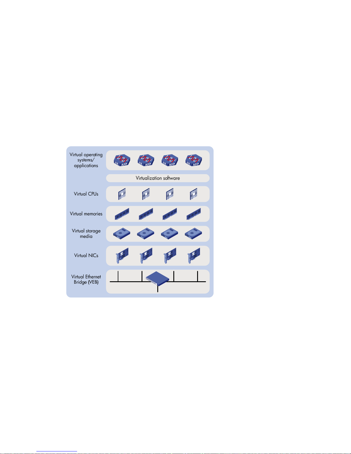
Data center virtualization includes network virtualization, storage virtualization, and server
virtualization. Server virtualization uses specific virtualization software such as VMware to create
VMs on a single physical server. Ea ch VM operates independently and has its own operating system ,
applications, and virtual hardware environments, as shown in Figure 1.
Figure
1 Server virtualization
VMs on a physical server communicate with each other or with the outside net work through a Virtual
Ethernet Bridge (VEB). VEBs are implemented through software or hardware such as NICs. Both
implementation methods have the following limitations:
• Lack of traffic monitoring capabilities such as packets statistics, traffic mirroring, and
NetStream.
• Lack of network policy enforcement capabilities, such as QoS.
• Lack of management scalability , especially in unified deployment of the internal server network
and the external network.
EVB solves these limitations. It uses a physical switch (called EVB bridge) to switch traffic for VMs on
a directly connected physical server (called EVB station). EVB implements traffic monitoring,
network policy enforcement, and unified network deployment and management for VMs.
Page 5
2
Basic concepts
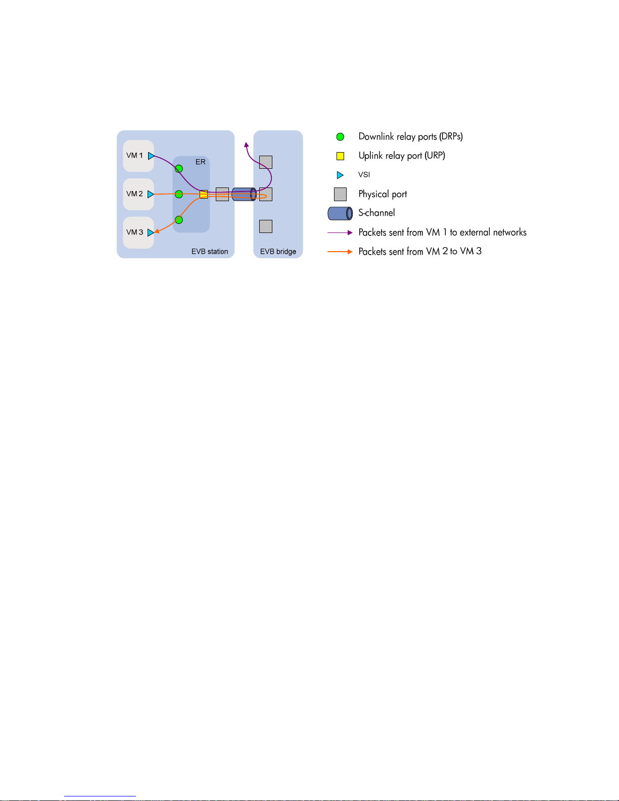
Figure 2 shows the components on the EVB station and EVB bridge.
Figure 2 EVB architecture
• Edge Relay (ER)—Transfers packets between one URP and one or more DRPs. An ER has
one or more DRPs and one URP. Both URP and DRPs are called ER ports. An EVB station can
have multiple ERs.
• S-channel—A point-to-point S-VLAN established between a Port-mapping S-VLAN component
in an EVB station and a Port-mapping S-VLAN component in an EVB bridge. An S-channel
corresponds to the URP of an ER. On an EVB bridge, the end point of an S-channel is known as
an S-channel interface. An S-channel is identified by the S-VLAN Identifier (SVID) and the
S-channel Identifier (SCID), and the two values together are called an (SCID, SVID) pair.
• Virtual Station Interface (VSI)—A port on a VM that directly connects to the DRP of an ER. A
VSI is associated with a logical entity called VSI instance, which is identified by th e VSI Instance
Identifier (VSIID). A VSI is associated with a virtual interface called VSI interface on the EVB
bridge port to implement VM traffic management and policy configuration. A VSI interface can
be considered a subinterface of an S-channel.
• Reflective Relay (RR)—An operation mode in which a received frame on a port that supports
this function can be forwarded out of the same port. The EVB bridge uses this mode to forward
traffic among VMs on an EVB station, as shown in Figure 2.
EVB working mechanism
An EVB station and an EVB bridge go through the following steps to implement VM traffic
management:
1. Use the S-channel Discovery and Configuration Protocol (CDCP) to establish an S-channel.
CDCP is used to configure S-channels between stations and bridges. When a sta tion creates or
deletes an S-channel, CDCP sends a CDCP TLV in an LLDP packet that is addressed using the
Nearest non-TPMR Bridge address to the bridge. The bridge creates or del etes the S-cha nnel.
2. Exchange EVB TLVs through LLDP to negotiate EVB capabilities for the S-channel, such as
RR, ECP parameters, and VDP parameters.
3. Use the VSI Discovery and Configuration Protocol (VDP) to associate the VSIs of VMs with the
bridge port.
The bridge uses the VSI interfaces to manage traffic for VMs.
VDP manages the association between a VSI and a station-facing bridge port (SBP) on a
bridge. VDP uses the Edge Control Protocol (ECP) to carry VDP TLVs. A VDP TLV comprises
the VSIID, VSI type, and VSI version.
When a station creates a VM, it sends a VDP pre-associate, pre-associate with resource
reservation, or associate packet to the bridge. The bridge sends the req uest to a VSI manager.
The VSI manager notifies the bridge to create a VSI interface and apply policies.
Page 6

3
When a station shuts down a VM, it sends a VDP de-associate packet to the bridge. The bridge
sends the request to the VSI manager. The VSI manager notifies the bridge to delete the VSI
interface.
Protocols and standards
IEEE P802.1Qbg/D2.2, Draft Standard for Local and Metropolitan Area Networks—MAC Bridges
and Virtual Bridged Local Area Networ ks—Amendment XX: Edge Virtual Bridging.
Configuration restrictions and guidelines
When you configure EVB, follow these restrictions and guidelines:
Hardware restrictions and guidelines
EVB is applicable only to interfaces on the following interface modules:
• EC interface modules.
• SE interface modules:
{ LSUM2GP44TSSE0(JH191A, JH199A).
{ LSUM2GT48SE0(JH192A, JH200A).
{ LSU1CGC2SE0(JG916A).
• SF interface modules.
• SG interface modules.
Traffic received from a port enabled with EVB can be forwarded only through interface cards that
support EVB.
Software restrictions and guidelines
Table 1 shows features incompatible with EVB and the references for these features.
Table 1 Features incompatible with EVB
Feature Reference
EVI
EVI Configuration Guide
VXLAN
VXLAN Configuration Guide
MPLS L2VPN
MPLS Configuration Guide
VLAN mapping
Layer 2—LAN Switching Configuration Guide
QinQ
MAC VLAN
Voice VLAN
MAC authentication
Security Configuration Guide
Port security
Do not create a service instance for an interface enabled with EVB, and vice versa.
Interfaces enabled with EVB cannot operate in route mode. For more information about Ethernet
interface link modes, see Interface Configuration Guide.
After you enable EVB on a Layer 2 Ethernet interface or a Layer 2 aggregate interface in a VLAN, the
interface does not support Layer 3 services.
Page 7

4
After you enable EVB on a Layer 2 Ethernet interface or a Layer 2 aggregate interface in a VLAN, the
interface does not support Layer 2 multicast services.
After you add an interface to a multiport unicast MAC address entry, the interface cannot forward
traffic received from interfaces enabled with EVB. For more information about multiport unicast MAC
address entries, see Layer 2—LAN Switching Configuration Guide.
Do not configure an interface enabled with EVB as the source or destination port for a mirroring
group. For more information about mirroring groups, see Network Management and Monitoring
Configuration Guide.
EVB configuration task list
This document only describes EVB bridge configuration. For information about EVB station
configuration, see the station manual.
Tasks at a glance
Enabling EVB
Configuring LLDP
(Optional.) Specifying a default VSI manager
(Optional.) Configuring VDP negotiation parameters
(Optional.) Configuring an S-channel:
• Creating an S-channel
• Configuring an S-channel interface or S-chan
nel aggregate interface
• Configuring the RR mode for an S-channel
• Configuring MAC address learning for an S-channel
(Optional.) Configuring a VSI interface or VSI aggregate interface:
• Creating a VSI interface or VS
I aggregate interface
• Configuring VSI filters
• Activating a VSI interface or VSI aggregate interface
Enabling EVB
Perform this task to enable EVB on an interface that directly connects to a station.
A default S-channel is created on an interface after EVB is enabled on the interface. Both SCID and
SVID are 1. After an S-channel is created, an S-channel interface or S-channel aggregate interface
is created and operates in access mode.
To enable EVB:
Step Command Remarks
1. Enter system view.
system-view
N/A
2. Enter Layer 2 Ethernet
interface view or Layer 2
aggregate interface view.
interface
interface-type
interface-number
N/A
3. Configure the interface to
operate in trunk mode.
port link-type trunk
By default, the interface operates
in access mode.
4. Enable EVB.
evb enable
By default, EVB is disabled on an
interface.
Page 8

5
Configuring LLDP
EVB uses LLDP to transmit CDCP TLVs, and CDCP TLVs are carried by the LLDP packet that is
addressed using the Nearest non-TPMR Bridge address, so you must configure LLDP.
For detailed information about the lldp global enable, lldp enable and lldp agent
nearest-nontpmr admin-status commands, see Layer 2—LAN Switching Command Reference.
To configure LLDP:
Step Command Remarks
1. Enter system view.
system-view
N/A
2. Enable LLDP globally.
lldp global enable
By default, LLDP is disabled
globally.
3. Enter Layer 2 Ethernet
interface view or Layer 2
aggregate interface view.
interface
interface-type
interface-number
N/A
4. Enable LLDP on the
interface
lldp enable
By default, LLDP is enabled on an
interface.
5. Configure the Nearest
non-TPMR Bridge agent for
LLDP to operate in TxRx
mode.
lldp agent nearest-nontpmr
admin-status txrx
The default mode is
disable
.
Specifying a default VSI manager
When the bridge receives a VDP packet (except for a De-Associate packet) from a station, it
contacts the VSI manager specified in the VDP packet to get VSI interface resource s and policies for
the station.
The VSI manager ID TLV in a VDP packet carries the VSI manager's IP address. If the value for the
TL V is 0, the VDP packet d oes not contain a VSI manager's IP address, so the bridge comm unicates
with the specified default VSI manager .
To specify a default VSI manager:
Step Command Remarks
1. Enter system view.
system-view
N/A
2. Specify a default VSI
manager.
evb default-manager
{ { ip
ip-address |
ipv6
ipv6-address |
name
name } [
port
port-number ]
|
local-server }
By default, no default VSI
manager is specified.
Configuring VDP negotiation parameters
After a station sends a VDP request other than a De-Associate request to the bridge, the bridge
requests the VSI interface resources and policies from the VSI manager. If the bridge receives no
response from the VSI manager before the VDP response-wait-delay time expires, the VDP
negotiation fails. The VDP response-wait-delay time on the EVB bridge is calculated as:
VDP response-wait-delay time (seconds) = 2
VDP resource-wait-delay
× 10—5.
Page 9

6
The value of the VDP resource wait-delay exponent is the larger of the values proposed by the
station and bridge through EVB TLV.
When a Pre-Associate, Pre-Associate with Resource Reservation, or Associate request from a
station is successfully handled, the VSI manager notifies the bridge to create a VSI interface for the
corresponding VM. Then the bridge starts a VDP keepalive timer for the VSI interface. If the bridge
receives no keepalive from the station before the timer expires, it releases resources reserved for the
association. The VDP keepalive time is calculated as:
VDP keepalive time (seconds) = 1.5 × [ 2
VDP keepalive
+ (2 × ECP maximum retransmission time + 1) ×
2
ECP retransmission
] × 10—5.
The value assigned to the VDP keepalive exponent, the ECP maximum retransmission time, and the
ECP retransmission exponent are the larger of the values proposed for each by the station and
bridge through EVB TLV.
To configure VDP negotiation parameters:
Step Command Remarks
1. Enter system view.
system-view
N/A
2. Enter Layer 2 Ethernet
interface view or Layer 2
aggregate interface view.
interface
interface-type
interface-number
N/A
3. Configure the VDP
resource-wait-delay timer
exponent.
evb vdp timer
resource-wait-delay exponent
value
The default is 20.
4. Configure the VDP keepalive
timer exponent.
evb vdp timer keepalive
exponent
value
The default is 20.
Configuring an S-channel
Creating an S-channel
An S-channel is automatically created by CDCP, and the system automatically saves the
configuration in the configuration file on the bridge. You can also manually create an S-channel by
performing this task. If an (SCID, SVID) pair for an S-channel is created both automatically and
manually, the one automatically created takes precedence.
After an S-channel is created, an S-channel interface or S-channel aggregate interface is generated.
Removing an S-channel also removes the S-channel interface or S-channel aggregate interface. A
manually created S-channel interface or S-channel aggregate interface operates in access mode.
An S-channel interface or S-channel aggregate interface that is automatically crea ted through CDCP
operates in trunk mode.
An S-channel interface is associated with the S-channel that is created on a Layer 2 Ethernet
interface. An S-channel aggregate interface is associated with the S-channel that is created on a
Layer 2 aggregate interface.
When you create an S-channel, follow these guidelines:
• Create an S-channel on an interface with EVB enabled. Otherwise, an error message appears.
• A default S-channel is created on an interface after EVB is enabled on the interface. Both SCID
and SVID are 1.
• When you manually create an S-channel, do not use the SCID or SVID being used by any other
S-channel. Otherwise, an error message appears.
• To manually create or remove S-channel, disable CDCP that automatically performs these
operations.
Page 10

7
To create an S-channel:
Step Command Remarks
1. Enter system view.
system-view
N/A
2. Enter Layer 2 Ethernet
interface view or Layer 2
aggregate interface view.
interface
interface-type
interface-number
N/A
3. Create an S-channel.
evb s-channel
channel-id
[
service-vlan
svlan-id ]
By default, only an automatically
created default S-channel (with
both SCID and SVID as 1) exists
on an interface with EVB enabled.
Configuring an S-channel interface or S-channel aggregate
interface
To configure an S-channel interface:
Step Command Remarks
1. Enter system view.
system-view
N/A
2. Enter S-channel interface
view.
interface s-channel
interface-number:channel-id
N/A
3. (Optional.) Configure the
expected bandwidth of the
S-channel interface.
bandwidth
bandwidth-value
By default, the expected
bandwidth of an S-channel
interface is the default maximum
bandwidth of the physical port to
which the S-channel interface
belongs.
4. (Optional.) Restore the
default settings for the
S-channel interface.
default
N/A
5. (Optional.) Configure a
description for the S-channel
interface.
description
text
The default description
information is "interface name
Interface."
6. Bring up the S-channel
interface.
undo shutdown
By default, the S-channel
interface is up.
To configure an S-channel aggregate interface:
Step Command Remarks
1. Enter system view.
system-view
N/A
2. Enter S-channel aggregate
interface view.
interface schannel-aggregation
interface-number:channel-id
N/A
3. (Optional.) Configure a
description for the
S-channel aggregate
interface.
description
text
The default description information
is "interface name Interface."
4. Bring up the S-channel
aggregate interface.
undo shutdown
By default, the S-channel
aggregate interface is up.
Page 11

8
Configuring the RR mode for an S-channel
EVB TLVs exchanged through LLDP allow an EVB station and EVB bridge to negotiate the use of
reflective relay. If the EVB bridge supports the RR mode, when the EVB station requests the use of
the RR mode, the bridge performs the following tasks:
• Automatically enables the RR mode for the S-channel.
• Saves the configuration in the configuration file on the bridge.
You can also manually enable the RR mode for an S-channel by performing this task.
To configure the RR mode for an S-channel:
Step Command Remarks
1. Enter system view.
system-view
N/A
2. Enter S-channel interface
view or S-channel
aggregate interface view.
interface
{
s-channel
|
schannel-aggregation
}
interface-number:channel-id
N/A
3. Enable the RR mode for the
S-channel.
evb reflective-relay
By default, the RR mode is
disabled for an S-channel.
Configuring MAC address learning for an S-channel
You can manually disable the MAC address learning function for an S-channel by performing this
task.
Follow these restrictions and guidelines when you configure MAC address learning for an S-ch annel:
• For an S-channel with the RR mode disabled, do not disable its MAC address learning function.
Otherwise, the bridge might fail to forward traffic for VMs on the EVB station.
• After you disable the MAC address learning function for an S-channel, the bridge will discard
packets with an unknown source MAC address.
• The undo evb mac-learning forbidden command and the mac-address mac-learning
enable command must be configured together to avoid communication interruption. For more
information about the mac-address mac-learning enable command, see Layer 2—LAN
Switching Command References.
To disable MAC address l earning for an S-channel:
Step Command Remarks
1. Enter system view.
system-view
N/A
2. Enter S-channel interface
view or S-channel
aggregate interface view.
interface
{
s-channel
|
schannel-aggregation
}
interface-number:channel-id
N/A
3. Disable MAC address
learning for the S-channel.
evb mac-learning forbidden
By default, the MAC address
learning function is enabled for
an S-channel.
Page 12

9
Configuring a VSI interface or VSI aggregate
interface
Creating a VSI interface or VSI aggregate interface
IMPORTANT:
When the total number of VSI interfaces and VSI aggregate interfaces on the device exceeds 512,
make sure the VDP keepalive exponent is larger than the default value. Otherwise, some VSI
interfaces or VSI aggregate interfaces might be automatically deleted.
A VSI interface is created on an S-chan nel interface th rough this task, and it is a subinterface of the
S-channel interface. A VSI aggregate interface is created on an S-channel aggregate interface, and
it is a subinterface of the S-channel aggregate interface. Removing an S-channel also removes all its
VSI interfaces and VSI aggregate interfaces.
VSI interfaces or VSI aggregate interfaces are typically created by a VSI manager . You can create a
VSI interface or VSI aggregate interface, or modify its Pre-Associate and Associate properties
through this task.
To create a VSI interface or VSI aggregate interface:
Step Command Remarks
1. Enter system view.
system-view
N/A
2. Enter S-channel interface
view or S-channel
aggregate interface view.
interface
{
s-channel
|
schannel-aggregation
}
interface-number:channel-id
N/A
3. Create a VSI interface or
VSI aggregate interface.
evb vsi
vsi-local-id {
association
|
pre-association }
By default, no VSI interface or
VSI aggregate interface exists on
an S-channel.
Configuring VSI filters
The EVB bridge uses VSI filters to identify VSI traffic. Typically a VSI manager assigns filters. You
can manually create or remove a VSI filter.
A VSI filter contains a set of VID values, MAC addresses, and group ID values. EVB supports the
following filter info formats:
• VLAN ID.
• VLAN ID + MAC.
• Group ID + VLAN ID.
• Group ID + VLAN ID + MAC.
When you configure a VSI filter on a VSI interface, follow these guidelines:
• For the VSI filter configuration to take effect, make sure the S-channel interface to which the
VSI interface belongs operates in trunk mode.
• When you create a VSI filter, the following interfaces automatically permit the VLAN contained
in the VSI filter:
{ The S-channel interface to which the VSI interface belongs.
{ The Layer 2 Ethernet interface where the S-channel that is associated with the S-channel
interface is created.
Page 13

10
• When you delete a VSI filter that contains information about a VLAN on a VSI interface, the
other VSI filters on all VSI interfaces of an S-channel interface might not contain the VLAN. If
they do not, the S-channel interface automatically denies traffic from the VLAN that is
configured on the VSI filter. The same rule takes effect on Layer 2 interfaces associated with
S-channels.
• When you delete a VSI filter, the following interfaces a utomatically deny the VLAN in the filter if
the VSI filters on the other VSI interfaces created on the same S-channel interface do not
contain the VLAN:
{ The S-channel interface to which the VSI interface belongs.
{ The Layer 2 Ethernet interface where the S-channel that is associated with the S-channel
interface is created.
• Do not create a VSI filter that contains the same VLAN on the same VSI interface or on other
VSI interfaces that belong to the same S-channel interface. If you do so, the system displays an
error message.
• Disabling MAC address learning for an S-channel prevents the traffic from the VSI from being
forwarded if the VSI filter contains the VLAN to which the traffic belongs.
• Activate a VSI interface after configuring a VSI filter , and deactivate a VSI interface before
removing a VSI filter.
When you configure VSI filters on a VSI aggregate interface, follow these guidelines:
• For the VSI filter configuration to take effect, make sure the S-channel aggregate interface to
which the VSI aggregate interface belongs operates in trunk mode.
• When you create a VSI filter, the following interfaces automatically permit the VLAN contained
in the VSI filter:
{ The S-channel aggregate interface to which the VSI aggregate interface belongs.
{ The Layer 2 aggregate interface where the S-channel that is associated with the S-channel
aggregate interface is created.
• When you delete a VSI filter, the following interfaces a utomatically deny the VLAN in the filter if
the VSI filters on the other VSI aggregate interfaces created on the same S-channel aggregate
interface do not contain the VLAN:
{ The S-channel aggregate interface to which the VSI aggregate interface belongs.
{ The Layer 2 aggregate interface where the S-channel that is associated with the S-channel
aggregate interface is created.
• Do not create a VSI filter that contains the same VLAN on the same VSI aggregate interface or
on other VSI aggregate interfaces that belong to the same S-channel aggregate interface. If you
do so, the system displays an error message.
• Activate a VSI aggregate interface after configuring a VSI filter , and deactivate a VSI aggregat e
interface before removing a VSI filter.
To configure a VSI filter:
Step Command Remarks
1. Enter system view.
system-view
N/A
2. Enter VSI interface view or
VSI aggregate interface
view.
interface
{
s-channel
|
schannel-aggregation
}
interface-number:channel-id.vsi-l
ocal-id
N/A
3. Configure a VSI filter.
evb vsi filter [ group
group-id ]
vlan
vlan-id [
mac
mac-address ]
By default, no VSI filter is
configured.
Page 14

11
Activating a VSI interface or VSI aggregate interface
Configurations such as traffic monitoring (see ACL and QoS Configuration Gui de) on a VSI interface
or VSI aggregate interface take effect only after the VSI interface or VSI aggregate interface is
activated. When a VSI interface or VSI aggregate interface is not activated, only configure filters on
the VSI interface or VSI aggregate interface.
Activate a VSI interface or VSI aggregate interface after configuring a VSI filter , and deactivate a VSI
interface or VSI aggregate interface before removing a VSI filter.
To activate a VSI interface:
Step Command Remarks
1. Enter system view.
system-view
N/A
2. Enter VSI interface
view.
interface s-channel
interface-number:channel-id.vsi-l
ocal-id
N/A
3. (Optional.) Configure
the expected bandwidth
of the VSI interface.
bandwidth
bandwidth-value
By default, the expected bandwidth of a
VSI interface is the default maximum
bandwidth of the physical port to which
the VSI interface belongs.
4. (Optional.) Restore the
default settings for the
VSI interface.
default
N/A
5. (Optional.) Configure a
description for the VSI
interface.
description
text
The default description information is
"interface name Interface."
6. Activate the VSI
interface.
evb vsi active
By default, no VSI interface is activated.
To activate a VSI aggregate interface:
Step Command Remarks
1. Enter system view.
system-view
N/A
2. Enter VSI aggregate
interface view.
interface schannel-aggregation
interface-number:channel-id.vsi-l
ocal-id
N/A
3. (Optional.) Configure a
description for the VSI
aggregate interface.
description
text
The default description
information is "interface name
Interface."
4. Activate the VSI aggregate
interface.
evb vsi active
By default, no VSI aggregate
interface is activated.
Displaying and maintaining EVB
Execute display commands in any view and the reset command in user view.
Task Command
Display CDCP negotiation
information.
display evb cdcp
[
interface
interface-type interface-number ]
Page 15
12
Task Command
Display S-channel EVB TLV
negotiation information.
display evb evb-tlv [ interface
interface-type { interface-number |
interface-number:channel-id } ]
Display S-channel information.
display evb s-channel
[
interface
interface-type interface-number ]
Display EVB summary.
display evb summary
Display VSI interface information.
display evb vsi
[
verbose
] [
interface
interface-type
{ interface-number | interface-number:channel-id |
interface-number:channel-id.vsi-local-id } ]
Display information about an
S-channel interface, S-channel
aggregate interface, VSI interface,
or a VSI aggregate interface.
display interface [ s-channel | schannel-aggregation
] [
brief
[
down
] ]
display interface
[{
s-channel | schannel-aggregation
}
[ interface-number:channel-id |
interface-number:channel-id.vsi-local-id ] ] [
brief
[
description
] ]
Clear statistics for an S-channel
interface, S-channel aggregate
interface, VSI interface, or a VSI
aggregate interface.
reset counters interface
[ {
s-channel
|
schannel-aggregation
}
[ interface-number:channel-id |
interface-number:channel-id.vsi-local-id ] ]
EVB configuration example
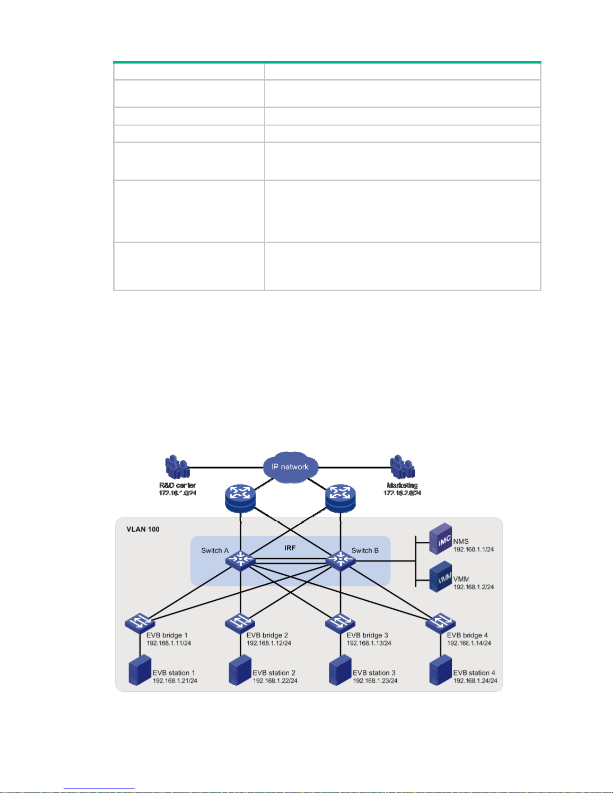
Network requirements
As shown in Figure 3, the Layer 2 network of a data center comprises two switches th at form an IRF
fabric, four EVB bridges, and four EVB stations. They communicate within VLAN 100.
Create VM 1 with MAC address 0050-5684-21C7 on EVB station 1, and set VM1 as the FTP server
with a CIR of 2048 kbps and a PIR of 4096 kbps. Only the R&D center is allowed to access the
network.
Figure 3 Network diagram
Page 16

13
Configuration procedure
This section only contains EVB configurations.
1. Configure the EVB bridge:
# Create VLAN 100 on EVB bridge 1.
<EVB_bridge1> system-view
[EVB_bridge1] vlan 100
[EVB_bridge1-vlan100] quit
# Enable EVB on GigabitEthernet 1/0/1 that connects to EVB station 1, and configure
GigabitEthernet 1/0/1 to operate in trunk mode.
[EVB_bridge1] interface gigabitethernet 1/0/1
[EVB_bridge1-GigabitEthernet1/0/1] evb enable
[EVB_bridge1-GigabitEthernet1/0/1] port link-type trunk
[EVB_bridge1-GigabitEthernet1/0/1] quit
# Enable LLDP on EVB bridge 1 globally. Enable LLDP on GigabitEthernet 1/0/1, and configure
the Nearest non-TPMR Bridge agent for LLDP to operate in TxRx mode.
[EVB_bridge1] lldp global enable
[EVB_bridge1] interface gigabitethernet 1/0/1
[EVB_bridge1-GigabitEthernet1/0/1] lldp enable
[EVB_bridge1-GigabitEthernet1/0/1] lldp agent nearest-nontpmr admin-status txrx
[EVB_bridge1-GigabitEthernet1/0/1] quit
# Specify the IP address and port number for the default VSI manager on EVB bridge 1.
[EVB_bridge1] evb default-manager ip 192.168.1.1 port 8080
Configure other EVB bridges in the same way. (Details are not shown.)
2. Configure the EVB station:
Configure the EVB station on the VMM. For more information about configuring VMs through
the VMM, see the VMM manual. (Details are not shown.)
3. Configure the NMS:
Use VAN Connection Manager of IMC on the NMS to configure network resources.
The IMC PLAT 5.2 (E0401) and IMC CRM 5.2 (E0401) versions are used in this section.
Page 17

14
Figure 4 VAN Connection Manager
To configure the NMS, log in to IMC, click the Resource tab, and select VAN Connection
Manager from the navigation tree (see Figure 4), an
d perform the following steps:
a. Add an EVB bridge (Edge Switch):
i Select Edge S witch from the navigation tree.
ii Click Add on the page that appe ars.
iii Select the four devices in the IP address range of 192.168.1.11 through 192.168.1.14
from IP View.
iv Click OK.
EVB bridge 1, EVB bridge 2, EVB bridge 3, and EVB bridge 4 are displayed in the Edge
Switch List page, as shown in Figure 5.
Figure 5
Edge Switch List page
b. Add an FTP network:
Select Net work from the navigation tree, click Add on the page that appears, enter For FTP
for Name, 100 for VLAN ID, and 10 for Max. Connections, and click OK.
The network name For FTP is displayed in the Network List page, as shown in Figure 6.
Page 18

15
Figure 6 Network List page
c. Define the VSI type of VM 1:
i Select VSI Type from the navigation tree. The VSI Type List page appears.
ii Click Add.
iii On the page that appears, do the following:
− Enter VM1 VSI for Name.
− Select For FTP from the Network list, and select the Bandwidth Control and VM
Access Control options.
− Enter 172.16.1.0 for Client IP and 0.0.0.255 for Wildcard Mask.
− Select BOTH from the Filtering Direction list.
− Enter 2048 for CIR (kbps) and 4096 for PIR (kbps).
iv Click Save and Release.
The VSI type VM1 VSI is displayed in the VSI Type List page, as shown in Figure 7.
Figure 7
VSI Type List page
d. Bind the VSI type VM1 VSI to the vNIC of VM 1 to define the connection:
i Select Connection from the navigation tree. The Connection List page appears.
ii Click Add.
iii On the page that appears, do the following:
− Enter VM1CON for Name.
− Click Select on the right side of the page, select the VM1 option from the popup window.
Then, click OK (the MAC address 0050-5684-21c7 of VM 1 is displayed in the vNIC
field).
− Select For FTP from the Network list, VM1 VSI from VSI Type, and VM1 VSI (V1) from
VSI Type Version.
iv Click OK.
The connection VM1CON is displayed in the Connection List page, as shown in Figure
8.
Page 19

16
Figure 8 Connection List page
4. Verify the configuration:
After VM 1 starts, the VAN Connection Manager service component of IMC deploys the VSI
type VM1 VSI on EVB bridge 1. Only the R&D center can use the FTP service on VM 1.
Page 20

17
Document conventions and icons
Conventions
This section describes the conventions used in the documentation.
Port numbering in examples
The port numbers in this document are for illustration only and might be unavailable on your device.
Command conventions
Convention Description
Boldface Bold
text represents commands and keywords that you enter literally as shown.
Italic
Italic text represents arguments that you replace with actual values.
[ ] Square brackets enclose syntax choices (keywords or arguments) that are optional.
{ x | y | ... }
Braces enclose a set of required syntax choices separated by vertical bars, from which
you select one.
[ x | y | ... ]
Square brackets enclose a set of optional syntax choices separated by vertical bars,
from which you select one or none.
{ x | y | ... } *
Asterisk marked braces enclose a set of required syntax choices separated by vertical
bars, from which you select at least one.
[ x | y | ... ] *
Asterisk marked square brackets enclose optional syntax choices separated by vertical
bars, from which you select one choice, multiple choices, or none.
&<1-n>
The argument or keyword and argument combination before the ampersand (&) sign
can be entered 1 to n times.
# A line that starts with a pound (#) sign is comments.
GUI conventions
Convention Description
Boldface
Window names, button names, field names, and menu items are in Boldface. For
example, the
New User
window appears; click OK.
>
Multi-level menus are separated by angle brackets. For example,
File
>
Create
>
Folder
.
Symbols
Convention Description
WARNING!
An alert that calls attention to important information that if not understood or followed
can result in personal injury.
CAUTION:
An alert that calls attention to important information that if not understood or followed
can result in data loss, data corruption, or damage to hardware or software.
IMPORTANT:
An alert that calls attention to essential information.
NOTE:
An alert that contains additional or supplementary information.
TIP:
An alert that provides helpful information.
Page 21

18
Network topology icons
Convention Description
Represents a generic network device, such as a router, switch, or firewall.
Represents a routing-capable device, such as a router or Layer 3 switch.
Represents a generic switch, such as a Layer 2 or Layer 3 switch, or a router that
supports Layer 2 forwarding and other Layer 2 features.
Represents an access controller, a unified wired-WLAN module, or the access
controller engine on a unified wired-WLAN switch.
Represents an access point.
Represents a wireless terminator unit.
Represents a wireless terminator.
Represents a mesh access point.
Represents omnidirectional signals.
Represents directional signals.
Represents a security product, such as a firewall, UTM, multiservice security
gateway, or load balancing device.
Represents a security card, such as a firewall, load balancing, NetStream, SSL VPN,
IPS, or ACG card.
T
T
T
T
Page 22

19
Support and other resources
Accessing Hewlett Packard Enterprise Support
• For live assistance, go to the Contact Hewlett Packard Enterprise Worldwide web site:
www.hpe.com/assistance
• To access documentation and support services, go to the Hewl ett Packard Enterprise Support
Center website:
www.hpe.com/support/hpesc
Information to collect
• Technical support registration number (if applicable)
• Product name, model or version, and serial number
• Operating system name and version
• Firmware version
• Error messages
• Product-specific reports and logs
• Add-on products or components
• Third-party products or components
Accessing updates
• Some software products provide a mechanism for accessing software updates through the
product interface. Review your product documentation to identify the recommended software
update method.
• To download product updat es, go to either of the following:
{ Hewlett Packard Enterprise Support Center Get connected with updates page:
www.hpe.com/support/e-updates
{ Software Depot website:
www.hpe.com/support/softwaredepot
• To view and update your entitlements, and to link your contracts, Care Packs, and warranties
with your profile, go to the Hewlett Packard Enterprise Support Center More Information on
Access to Support Materials page:
www.hpe.com/support/AccessToSupportMaterials
IMPORTANT:
A
ccess to some updates might require product entitlement when accessed through the Hewlett
Packard Enterprise Support Center. You must have an HP Passport set up with relevant
entitlements.
Page 23

20
Websites
Website Link
Networking websites
Hewlett Packard Enterprise Information Library for
Networking
www.hpe.com/networking/resourcefinder
Hewlett Packard Enterprise Networking website www.hpe.com/info/networking
Hewlett Packard Enterprise My Networking website www.hpe.com/networking/support
Hewlett Packard Enterprise My Networking Portal www.hpe.com/networking/mynetworking
Hewlett Packard Enterprise Networking Warranty www.hpe.com/networking/warranty
General websites
Hewlett Packard Enterprise Information Library www.hpe.com/info/enterprise/docs
Hewlett Packard Enterprise Support Center www.hpe.com/support/hpesc
Hewlett Packard Enterprise Support Services Central ssc.hpe.com/portal/site/ssc/
Contact Hewlett Packard Enterprise Worldwide www.hpe.com/assistance
Subscription Service/Support Alerts www.hpe.com/support/e-u pdates
Software Depot www.hpe.com/support/softwaredepot
Customer Self Repair (not applicable to all devices) www.hpe.com/support/selfrepair
Insight Remote Support (not applicable to all devices) www.hpe.com/info/insightremotesupport/docs
Customer self repair
Hewlett Packard Enterprise customer self repair (CSR) programs allow you to repair yo ur product. If
a CSR part needs to be replaced, it will be shipped directly to you so that you can install it at your
convenience. Some parts do not qualify for CSR. Your Hewlett Packard Enterprise authorized
service provider will determine whether a repair can be accomplished by CSR.
For more information about CSR, contact your local service provider or go to the CSR website:
www.hpe.com/support/selfrepair
Remote support
Remote support is available with supported devices as part of your warranty, Care Pack Service, or
contractual support agreement. It provides intelligent event diagnosis, and automatic, secure
submission of hardware event notifications to Hewlett Packard Enterprise, which will initiate a fast
and accurate resolution based on your product’s service level. Hewlett Packard Enterprise strongly
recommends that you register your device for remote support.
For more information and device support details, go to the following website:
www.hpe.com/info/insightremotesupport/docs
Documentation feedback
Hewlett Packard Enterprise is committed to providing documentation that meets your needs. To help
us improve the documentation, send any errors, suggestions, or comments to Documentation
Feedback (docsfeedback@hpe.com
). When submitting your feedback, include the document title,
Page 24

21
part number, edition, and publication date located on the front cover of the document. For online help
content, include the product name, product version, help edition, and publication date located on the
legal notices page.
Page 25

22
Index
A
activating
EVB VSI aggregate interface filter, 11
EVB VSI
filter, 11
B
bridgi
ng
EVB configuration, 1, 4, 12
EVB default VSI manager
, 5
EVB LLDP
configuration, 5
EVB S-channel aggregate i
nterface, 7
EVB S-channel configurati
on, 6
EVB S-channel interface, 7
EVB S-channel MAC address learni
ng, 8
EVB S-channel RR mode, 8
EVB S-channel VSI aggregate
config
uration, 9
EVB S-channel VSI configuration, 9
EVB VDP
negotiation parameter, 5
C
cha
nnel
EVB S-channel configuration, 6
config
uring
EVB, 1, 4, 12
EVB LLDP
, 5
EVB S-channel, 6
EVB S-channel aggregate i
nterface, 7
EVB S-channel interface, 7
EVB S-channel MAC address learni
ng, 8
EVB S-channel RR mode, 8
EVB S-channel VSI, 9
EVB S-channel VSI aggregate, 9
EVB VDP
negotiation parameter, 5
EVB VSI
filter, 9
cre
ating
EVB S-channel, 6
EVB VSI
, 9
EVB VSI aggregate interface, 9
D
default
EVB default VSI manager, 5
displ
aying
EVB, 11
E
edge
EVB edge relay, 2
Edge V
irtual Bridging. Use EVB
enabli
ng
EVB, 4
EVB
basi
c concepts, 2
config
uration, 1, 4, 12
default VSI manag
er, 5
displ
aying, 11
edge relay
, 2
enabl
e, 4
how it wo
rks, 2
LLDP
configuration, 5
maintaining, 11
proto
cols and standards, 3
reflec
tive relay, 2
S-ch
annel, 2
S-ch
annel aggregate interface configuration, 7
S-ch
annel configuration, 6
S-ch
annel creation, 6
S-ch
annel interface configuration, 7
S-ch
annel MAC address learning configuration, 8
S-ch
annel RR mode configuration, 8
S-ch
annel VSI aggregate configuration, 9
S-ch
annel VSI configuration, 9
VDP
negotiation parameter , 5
virtual station
interface, 2
VSI aggregat
e interface filter activation, 11
VSI fil
ter activation, 11
VSI filter conf
iguration, 9
F
filtering
EVB VSI
filter configuration, 9
L
LLDP
EVB LLDP configuration, 5
M
MAC add
ressing
EVB S-channel MAC address learning, 8
maintaining
EVB, 11
mode
EVB S-channel RR mode, 8
N
Page 26

23
network
EVB default VSI manager, 5
EVB LLDP
configuration, 5
EVB S-channel aggregate i
nterface, 7
EVB S-channel configurati
on, 6
EVB S-channel interface, 7
EVB S-channel MAC address learni
ng, 8
EVB S-channel RR mode, 8
EVB S-channel VSI aggregate
config
uration, 9
EVB S-channel VSI configuration, 9
EVB VDP
negotiation parameters, 5
EVB VSI aggregate interface filter
activation, 11
EVB VSI
filter activation, 11
EVB VSI
filter configuration, 9
netwo
rk management
EVB configuration, 1, 4, 12
P
para
meter
EVB VDP negotiation parameters, 5
port
EVB configuration, 1, 4, 12
pro
cedure
activating EVB VSI aggregate interface
filter, 11
ac
tivating EVB VSI filter, 11
c
onfiguring EVB, 4, 12
c
onfiguring EVB LLDP, 5
c
onfiguring EVB S-channel, 6
configuring EVB S-channel
aggregate
interface, 7
c
onfiguring EVB S-channel interface, 7
configuring EVB S-channel
MAC address
learning, 8
c
onfiguring EVB S-channel RR mode, 8
c
onfiguring EVB S-channel VSI, 9
configuring EVB S-channel
VSI aggregate, 9
configuring EVB VDP
negotiation
parameter, 5
c
onfiguring EVB VSI filter, 9
c
reating EVB S-channel, 6
c
reating EVB VSI, 9
creating EVB VSI aggregat
e interface, 9
dis
playing EVB, 11
enabli
ng EVB, 4
maintaining EVB, 11
specifying EVB default VSI
manager, 5
proto
cols and standards
EVB, 3
R
reflec
tive relay
EVB RR, 2
EVB S-channel RR mode, 8
routing
EVB configuration, 1, 4, 12
S
S-ch
annel
EVB, 2
EVB c
onfiguration, 6
EVB c
reation, 6
EVB interfac
e configuration, 7
EVB MAC address learning, 8
EVB RR mode c
onfiguration, 8
EVB VSI aggregate
configuration, 9
EVB VSI aggregate interface filter activation, 11
EVB VSI
configuration, 9
EVB VSI
filter activation, 11
EVB VSI
filter configuration, 9
spe
cifying
EVB default VSI manager, 5
T
TL
V
EVB default VSI manager, 5
EVB LLDP
configuration, 5
traf
fic management
EVB VSI aggregate interface filter, 11
EVB VSI
filter, 9, 11
V
VDP
EVB negotiation parameters, 5
virtual
EVB virtual s
tation interface. See VSI
V
irtual Ethernet Bridge. Use VEB
VSI
aggregate configuration, 9
aggregate int
erface creation, 9
aggregate int
erface filter activation, 11
config
uration, 9
cre
ation, 9
Discove
ry Configuration Protocol. See VDP
EVB default VSI manager
, 5
EVB virtual s
tation interface, 2
filter activation, 11
filter configu
ration, 9
VDP
negotiation parameter , 5
 Loading...