

Page 1

HPE FlexFabric 7900 Switch Series
Security
Configuration Guide
Part number: 5998-8250R
Software version: Release 213x
Document version: 6W101-20151113
Page 2

© Copyright 2015 Hewlett Packard Enterprise Development LP
The information contained herein is subject to change without notice. The only warranties for Hewlett Packard
Enterprise products and services are set forth in the express warranty statements acco mpanying such
products and services. Nothing herein should be construe d as constituting an additional warranty. Hewlett
Packard Enterprise shall not be liable for technical or editorial errors or omissions co ntained herein.
Confidential computer software. V alid license from Hewlett Packard Enterprise required for possession, use, or
copying. Consistent with FAR 12.211 and 12.212, Commercial Computer Software, Computer Software
Documentation, and T e chnical Data for Commercial Items are licensed to the U.S. Government under vendor’s
standard commercial license.
Links to third-party websites take you outside the Hewlett Packard Enterprise website. Hewlett Packard
Enterprise has no control over and is not responsible for information outside the Hewlett Packard Enterprise
website.
Acknowledgments
Intel®, Itanium®, Pentium®, Intel Inside®, and the Intel Inside logo are trademarks of Intel Corporation in the
United States and other countries.
Microsoft® and Windows® are trademarks of the Microsoft group of companies.
Adobe® and Acrobat® are trademarks of Adobe Systems In corporated.
Java and Oracle are registered trademarks of Oracle and/or its affiliates.
UNIX® is a registered trademark of The Open Group.
Page 3

Contents
Configuring AAA ····························································································· 1
Overview ···························································································································································· 1
RADIUS ······················································································································································ 2
HWTACACS ··············································································································································· 6
AAA implementation on the device ············································································································ 9
Protocols and standards ·························································································································· 10
RADIUS attributes ···································································································································· 11
FIPS compliance ·············································································································································· 14
AAA configuration considerations and task list ································································································ 14
Configuring AAA schemes ······························································································································· 15
Configuring local users ····························································································································· 15
Configuring RADIUS schemes ················································································································· 18
Configuring HWTACACS schemes ·········································································································· 27
Configuring AAA methods for ISP domains ····································································································· 33
Configuration prerequisites ······················································································································ 33
Creating an ISP domain ··························································································································· 33
Setting the ISP domain status ·················································································································· 34
Configuring authentication methods for an ISP domain ··········································································· 34
Configuring authorization methods for an ISP domain ············································································· 35
Configuring accounting methods for an ISP domain ················································································ 36
Enabling the session-control feature ················································································································ 37
Setting the maximum number of concurrent login users ·················································································· 37
Displaying and maintaining AAA ······················································································································ 37
AAA configuration examples ···························································································································· 38
AAA for SSH users by an HWTACACS server ························································································ 38
Local authentication, HWTACACS authorization, and RADIUS accounting for SSH users ····················· 39
Authentication and authorization for SSH users by a RADIUS server ····················································· 41
Troubleshooting RADIUS ································································································································· 44
RADIUS authentication failure ················································································································· 44
RADIUS packet delivery failure ················································································································ 45
RADIUS accounting error ························································································································· 45
Troubleshooting HWTACACS ·························································································································· 45
Configuring password control ······································································· 46
Overview ·························································································································································· 46
Password setting ······································································································································ 46
Password updating and expiration ··········································································································· 47
User login control ····································································································································· 48
Password not displayed in any form ········································································································ 48
Logging ···················································································································································· 48
FIPS compliance ·············································································································································· 49
Password control configuration task list ··········································································································· 49
Enabling password control ······························································································································· 49
Setting global password control parameters ···································································································· 50
Setting user group password control parameters ···························································································· 51
Setting local user password control parameters ······························································································ 51
Setting super password control parameters ···································································································· 52
Displaying and maintaining password control ·································································································· 53
Password control configuration example ········································································································· 53
Network requirements ······························································································································ 53
Configuration procedure ··························································································································· 54
Verifying the configuration ························································································································ 55
Managing public keys ··················································································· 57
Overview ·························································································································································· 57
FIPS compliance ·············································································································································· 57
Creating a local key pair ·································································································································· 57
i
Page 4

Configuration guidelines ··························································································································· 57
Configuration procedure ··························································································································· 58
Distributing a local host public key ··················································································································· 58
Exporting a host public key in a specific format to a file ··········································································· 59
Displaying a host public key in a specific format and saving it to a file ···················································· 59
Displaying a host public key ····················································································································· 59
Destroying a local key pair ······························································································································· 60
Configuring a peer public key ·························································································································· 60
Importing a peer host public key from a public key file ············································································ 61
Entering a peer public key ························································································································ 61
Displaying and maintaining public keys ··········································································································· 61
Examples of public key management ·············································································································· 61
Example for entering a peer public key ···································································································· 61
Example for importing a public key from a public key file ········································································ 63
Configuring PKI ····························································································· 66
Overview ·························································································································································· 66
PKI terminology ········································································································································ 66
PKI architecture ········································································································································ 67
PKI operation ··········································································································································· 67
PKI applications ······································································································································· 68
Support for MPLS L3VPN ························································································································ 68
Feature and software version compatibility ······································································································ 69
FIPS compliance ·············································································································································· 69
PKI configuration task list ································································································································· 69
Configuring a PKI entity ··································································································································· 69
Configuring a PKI domain ································································································································ 70
Requesting a certificate ··································································································································· 72
Configuration guidelines ··························································································································· 72
Configuring automatic certificate request ································································································· 73
Manually requesting a certificate ·············································································································· 73
Aborting a certificate request ··························································································································· 74
Obtaining certificates ······································································································································· 74
Configuration prerequisites ······················································································································ 74
Configuration guidelines ··························································································································· 74
Configuration procedure ··························································································································· 75
Verifying PKI certificates ·································································································································· 75
Verifying certificates with CRL checking ·································································································· 75
Verifying certificates without CRL checking ····························································································· 76
Specifying the storage path for the certificates and CRLs ··············································································· 76
Exporting certificates ········································································································································ 77
Removing a certificate ····································································································································· 77
Configuring a certificate-based access control policy ······················································································ 78
Displaying and maintaining PKI ······················································································································· 79
PKI configuration examples ····························································································································· 79
Requesting a certificate from an RSA Keon CA server ············································································ 79
Requesting a certificate from a Windows Server 2003 CA server ··························································· 82
Requesting a certificate from an OpenCA server ····················································································· 85
Certificate import and export configuration example ················································································ 88
Troubleshooting PKI configuration ··················································································································· 93
Failed to obtain the CA certificate ············································································································ 94
Failed to obtain local certificates ·············································································································· 94
Failed to request local certificates ············································································································ 95
Failed to obtain CRLs ······························································································································· 95
Failed to import the CA certificate ············································································································ 96
Failed to import a local certificate ············································································································· 97
Failed to export certificates ······················································································································ 97
Failed to set the storage path ··················································································································· 98
Configuring SSL ···························································································· 99
Overview ·························································································································································· 99
SSL security services ······························································································································· 99
ii
Page 5

SSL protocol stack ··································································································································· 99
Feature and software version compatibility ···································································································· 100
FIPS compliance ············································································································································ 100
SSL configuration task list ······························································································································ 100
Configuring an SSL server policy ··················································································································· 100
Configuring an SSL client policy ···················································································································· 102
Displaying and maintaining SSL ···················································································································· 103
Configuring IPsec ························································································ 104
Overview ························································································································································ 104
Security protocols and encapsulation modes ························································································· 104
Security association ······························································································································· 106
Authentication and encryption ················································································································ 106
IPsec implementation ····························································································································· 107
Protocols and standards ························································································································ 107
IPsec tunnel establishment ···························································································································· 108
Implementing ACL-based IPsec ···················································································································· 108
Feature restrictions and guidelines ········································································································ 108
ACL-based IPsec configuration task list ································································································· 108
Configuring an ACL ································································································································ 109
Configuring an IPsec transform set ········································································································ 110
Configuring a manual IPsec policy ········································································································· 111
Configuring an IKE-based IPsec policy ·································································································· 112
Applying an IPsec policy to an interface ································································································ 114
Enabling ACL checking for de-encapsulated packets ············································································ 115
Configuring the IPsec anti-replay function ····························································································· 115
Binding a source interface to an IPsec policy ························································································ 116
Enabling QoS pre-classify ······················································································································ 116
Enabling logging of IPsec packets ········································································································· 117
Configuring the DF bit of IPsec packets ································································································· 117
Configuring SNMP notifications for IPsec ······································································································ 118
Displaying and maintaining IPsec ·················································································································· 118
IPsec configuration examples ························································································································ 119
Configuring a manual mode IPsec tunnel for IPv4 packets ··································································· 119
Configuring an IKE-based IPsec tunnel for IPv4 packets ······································································ 121
Configuring IKE ··························································································· 125
Overview ························································································································································ 125
IKE negotiation process ························································································································· 125
IKE security mechanism ························································································································· 126
Protocols and standards ························································································································ 127
IKE configuration prerequisites ······················································································································ 127
IKE configuration task list ······························································································································· 127
Configuring an IKE profile ······························································································································ 128
Configuring an IKE proposal ·························································································································· 129
Configuring an IKE keychain ·························································································································· 131
Configuring the global identity information ····································································································· 131
Configuring the IKE keepalive function ·········································································································· 132
Configuring the IKE NAT keepalive function ·································································································· 132
Configuring IKE DPD ····································································································································· 133
Enabling invalid SPI recovery ························································································································ 133
Setting the maximum number of IKE SAs ······································································································ 134
Configuring SNMP notifications for IKE ········································································································· 134
Displaying and maintaining IKE ····················································································································· 135
Main mode IKE with pre-shared key authentication configuration example ·················································· 135
Network requirements ···························································································································· 135
Configuration procedure ························································································································· 135
Verifying the configuration ······················································································································ 138
Troubleshooting IKE ······································································································································ 138
IKE negotiation failed because no matching IKE proposals were found ················································ 138
IKE negotiation failed because no IKE proposals or IKE keychains are referenced correctly ··············· 138
IPsec SA negotiation failed because no matching IPsec transform sets were found ···························· 139
iii
Page 6

IPsec SA negotiation failed due to invalid identity information ······························································· 140
Configuring SSH ························································································· 143
Overview ························································································································································ 143
How SSH works ····································································································································· 143
SSH authentication methods ·················································································································· 144
FIPS compliance ············································································································································ 145
Configuring the device as an SSH server ······································································································ 145
SSH server configuration task list ·········································································································· 145
Generating local DSA or RSA key pairs ································································································· 146
Enabling the Stelnet server ···················································································································· 147
Enabling the SFTP server ······················································································································ 147
Enabling the SCP server ························································································································ 147
Configuring NETCONF over SSH ·········································································································· 147
Configuring user lines for SSH login ······································································································ 148
Configuring a client's host public key ····································································································· 148
Configuring an SSH user ······················································································································· 149
Configuring the SSH management parameters ····················································································· 150
Configuring the device as an Stelnet client ···································································································· 151
Stelnet client configuration task list ········································································································ 151
Specifying a source IP address for SSH packets··················································································· 151
Establishing a connection to an Stelnet server ······················································································ 152
Configuring the device as an SFTP client ······································································································ 153
SFTP client configuration task list ·········································································································· 153
Specifying the source IP address for SFTP packets ·············································································· 153
Establishing a connection to an SFTP server ························································································ 153
Working with SFTP directories ··············································································································· 154
Working with SFTP files ························································································································· 154
Displaying help information ···················································································································· 155
Terminating the connection with the SFTP server ················································································· 155
Configuring the device as an SCP client ········································································································ 155
Displaying and maintaining SSH ···················································································································· 156
Stelnet configuration examples ······················································································································ 156
Password authentication enabled Stelnet server configuration example ··············································· 157
Publickey authentication enabled Stelnet server configuration example ··············································· 159
Password authentication enabled Stelnet client configuration example ················································ 165
Publickey authentication enabled Stelnet client configuration example ················································· 168
SFTP configuration examples ························································································································ 170
Password authentication enabled SFTP server configuration example ················································· 170
Publickey authentication enabled SFTP client configuration example ··················································· 172
SCP file transfer with password authentication ······························································································ 175
Network requirements ···························································································································· 176
Configuration procedure ························································································································· 176
Configuring IP source guard ······································································· 178
Overview ························································································································································ 178
Static IPSG bindings ······························································································································ 178
Dynamic IPSG bindings ························································································································· 179
IPSG configuration task list ···························································································································· 179
Configuring the IPv4SG feature ····················································································································· 179
Enabling IPv4SG on an interface ··········································································································· 179
Configuring a static IPv4SG binding ······································································································ 180
Displaying and maintaining IPSG ·················································································································· 181
IPSG configuration examples ························································································································ 181
Static IPv4SG configuration example ····································································································· 181
Dynamic IPv4SG using DHCP snooping configuration example ··························································· 182
Dynamic IPv4SG using DHCP relay configuration example ·································································· 183
Configuring ARP attack protection ······························································ 185
ARP attack protection configuration task list ·································································································· 185
Configuring unresolvable IP attack protection ······························································································· 185
Configuring ARP source suppression ···································································································· 186
iv
Page 7

Configuring ARP blackhole routing ········································································································ 186
Displaying and maintaining unresolvable IP attack protection ······························································· 186
Configuration example ··························································································································· 187
Configuring ARP packet rate limit ·················································································································· 188
Configuration guidelines ························································································································· 188
Configuration procedure ························································································································· 188
Configuring source MAC-based ARP attack detection ·················································································· 189
Configuration procedure ························································································································· 189
Displaying and maintaining source MAC-based ARP attack detection ·················································· 189
Configuration example ··························································································································· 190
Configuring ARP packet source MAC consistency check ·············································································· 191
Configuring ARP active acknowledgement ···································································································· 191
Configuring authorized ARP ·························································································································· 192
Configuration procedure ························································································································· 192
Configuring ARP detection ····························································································································· 192
Configuring user validity check ·············································································································· 192
Configuring ARP packet validity check ·································································································· 193
Configuring ARP restricted forwarding ··································································································· 194
Enabling ARP detection logging ············································································································· 194
Displaying and maintaining ARP detection ···························································································· 195
User validity check and ARP packet validity check configuration example ············································ 195
Configuring ARP scanning and fixed ARP ····································································································· 196
Configuration restrictions and guidelines ······························································································· 197
Configuration procedure ························································································································· 197
Configuring ARP gateway protection ············································································································· 197
Configuration guidelines ························································································································· 197
Configuration procedure ························································································································· 198
Configuration example ··························································································································· 198
Configuring ARP filtering ································································································································ 199
Configuration guidelines ························································································································· 199
Configuration procedure ························································································································· 199
Configuration example ··························································································································· 199
Configuring uRPF ······················································································· 201
Overview ························································································································································ 201
uRPF check modes ································································································································ 201
uRPF operation ······································································································································ 201
Network application ································································································································ 204
Configuring uRPF ·········································································································································· 204
Displaying and maintaining uRPF ·················································································································· 204
uRPF configuration example ·························································································································· 205
Configuring FIPS ························································································· 206
Overview ························································································································································ 206
Configuration restrictions and guidelines ······································································································· 206
Configuring FIPS mode ·································································································································· 207
Entering FIPS mode ······························································································································· 207
Configuration changes in FIPS mode ···································································································· 208
Exiting FIPS mode ································································································································· 208
FIPS self-tests ················································································································································ 209
Power-up self-tests ································································································································ 209
Conditional self-tests ······························································································································ 210
Triggering self-tests ································································································································ 210
Displaying and maintaining FIPS ··················································································································· 210
FIPS configuration examples ························································································································· 211
Entering FIPS mode through automatic reboot ······················································································ 211
Entering FIPS mode through manual reboot ·························································································· 212
Exiting FIPS mode through automatic reboot ························································································ 213
Exiting FIPS mode through manual reboot ···························································································· 214
Configuring attack detection and prevention ··············································· 215
Overview ························································································································································ 215
v
Page 8

Enabling TCP fragment attack prevention ····································································································· 215
Document conventions and icons ······························································· 216
Conventions ··················································································································································· 216
Network topology icons ·································································································································· 217
Support and other resources ······································································ 218
Accessing Hewlett Packard Enterprise Support ···························································································· 218
Accessing updates ········································································································································· 218
Websites ················································································································································ 219
Customer self repair ······························································································································· 219
Remote support ······································································································································ 219
Documentation feedback ······················································································································· 219
Index ··········································································································· 220
vi
Page 9
Configuring AAA
Overview
Authentication, Authorization, and Accounting (AAA) provides a uniform framework for implementing
network access management. This feat ure specifies the following security functions:
• Authentication—Identifies users and verifies their validity.
• Authorization—Grants different users different rights, and controls the users' access to
resources and services. For example, you can permit office users to read and print files and
prevent guests from accessing files on the device.
• Accounting—Records network usage details of users, including the service type, start time,
and traffic. This function enables time-based and traffic-based charging and user behavior
auditing.
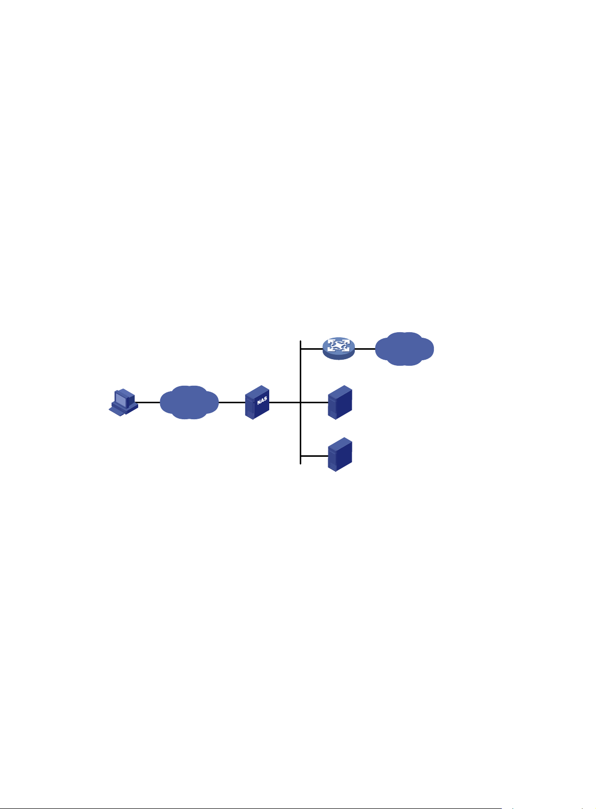
AAA uses a client/server m odel. The clie nt runs on the access d evice, or the net work access se rver
(NAS), which authenticates user identities and controls user access. The server maintains user
information centrally. See Figure 1.
Figure 1
Remote user
To access networks or resources beyond the NAS, a user sends its identity information to the NAS.
The NAS transparently passes the user information to AAA servers and waits for the authentication,
authorization, and accounting result. Based on the result, the NAS determines whether to permit or
deny the access request.
AAA has vari ous implementations, including RADIUS and HWT ACACS. RADIUS is most ofte n used.
The network in Figure 1 ha
servers to implement different security functions. For example, you can use the HWTACACS server
for authentication and authorization, and use the RADIUS server for accounting.
AAA network diagram
Network
s one RADIUS server and one HWT A CACS server. You can use dif ferent
NAS
RADIUS server
HWTACACS server
Internet
You can choose the security functions provided by AAA as needed. For example, if your company
wants employees to be authenticated before they access specific resources, you would deploy an
authentication server. If network usage information is needed, you would also configure an
accounting server.
The device performs dynamic password authentication.
1
Page 10
RADIUS
Remote Authentication Dial-In User Service (RADIUS) is a distributed information interaction
protocol that uses a client/server model. The protocol can protect networks against unauthorized
access and is often used in network environments that require both high security and remote user
access.
The RADIUS authorization process is combined with the RADIUS authentication process, and user
authorization information is piggybacked in authentication responses. RADIUS uses UDP port 1812
for authentication and UDP port 1813 for accounting.
RADIUS was originally designed for dial-in user access, and has been extended to support
additional access methods, such as Ethernet and ADSL.
Client/server model
The RADIUS client runs on the NASs located throughout the network. It passes user information to
RADIUS servers and acts on the responses to, for example, reject or accept user access requests.
The RADIUS server runs on the computer or workstation at the network center and maintains
information related to user authentication and network service access.
The RADIUS server operates using the following process:
1. Receives authentication, authorization, and accounting requests from RADIUS clients.
2. Performs user authentication, authorization, or accounting.
3. Returns user access control information (for example, rejecting or accepting the user acce ss
request) to the clients.
The RADIUS server can also act as the client of another RADIUS server to provide authentication
proxy services.
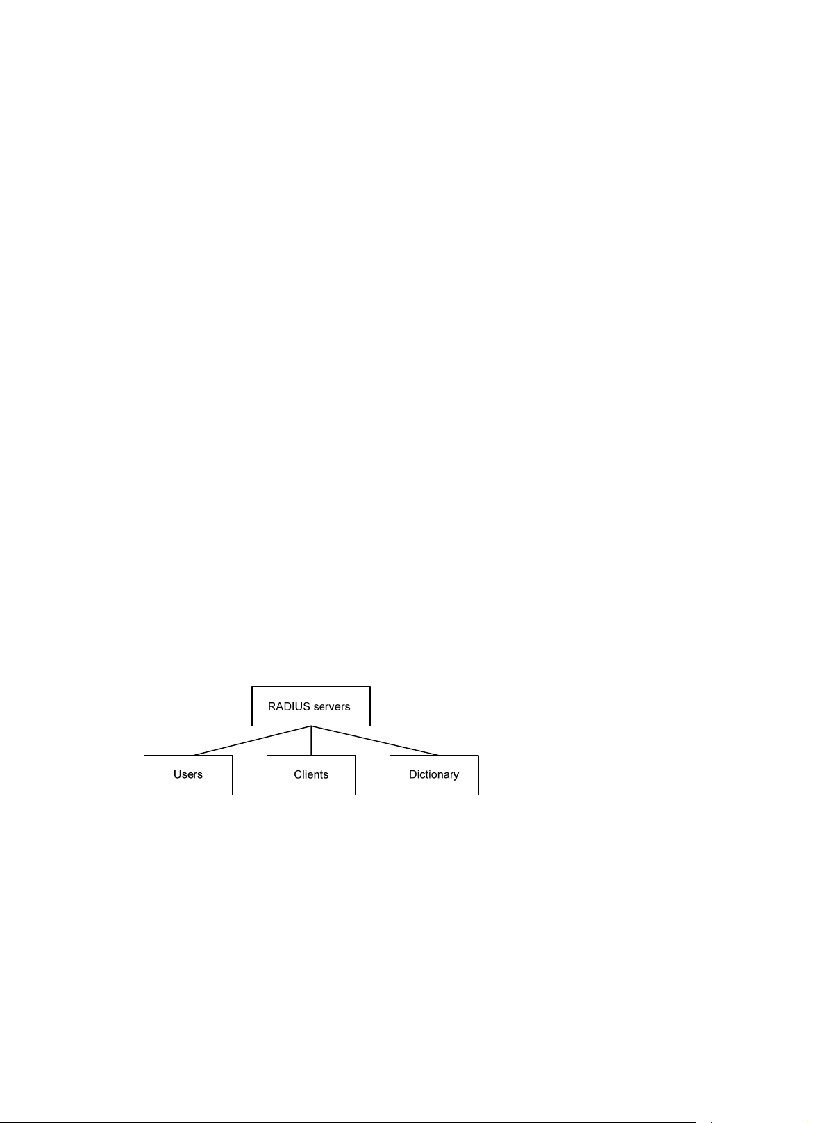
The RADIUS server maintains the following databases:
• Users—Stores user information, such as the usernames, passwords, applied protocols, and IP
addresses.
• Clients—Stores information about RADIUS clients, such as shared keys and IP addresses.
• Dictionary—Stores RADIUS protocol attributes and their values.
Figure 2 RADIUS server databases
Information exchange security mechanism
The RADIUS client and server exchange information between them with the help of shared keys,
which are preconfigured on the client and server. A RADIUS packet has a 16-byte field called
Authenticator. This field includes a signature ge nerated by using the MD5 algorithm, the shared key,
and some other information. The receiver of the packet verifies the si gnature and accepts the packet
only when the signature is correct. This mechanism ensures the security of information exchanged
between the RADIUS client and server.
The shared keys are also used to encrypt user passwords that are included in RADIUS packets.
User authentication methods
The RADIUS server supports multiple user authentication methods, such as PAP, CHAP, and EAP.
2
Page 11
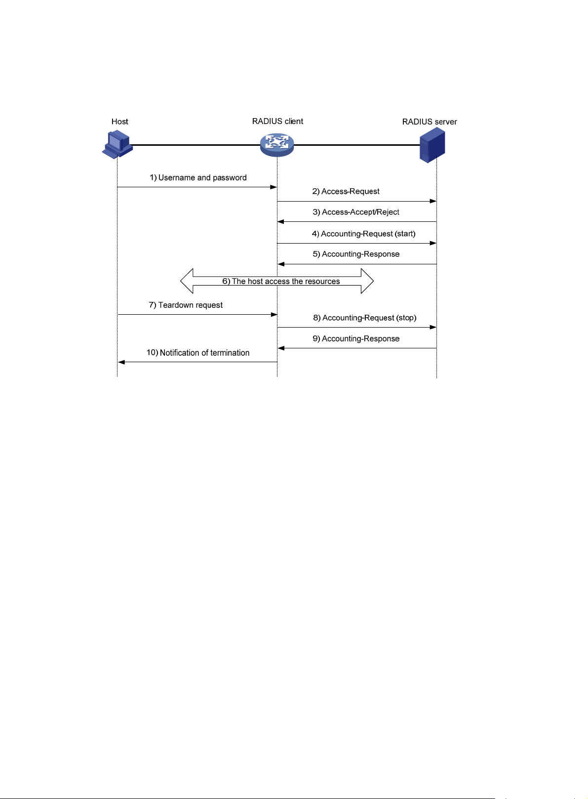
Basic RADIUS packet exchange process
Figure 3 illustrates the interactions between a user host, the RADIUS client, and the RADIUS server.
Figure 3 Basic RADIUS packet exchange process
RADIUS uses the following workflow:
1. The host sends a connection request that includes the user's username and password to the
RADIUS client.
2. The RADIUS client sends an authentication request (Access-Request) to the RADIUS server.
The request includes the user's password, which has been processed by the MD5 algorithm
and shared key.
3. The RADIUS server authenticates the username and password. If the authenticati on succeeds,
the server sends back an Access-Accept packet that contains the user's authorization
information. If the authentication fails, the server returns an Access-Reject packet.
4. The RADIUS client permits or denies the user according to the authentication result. If the result
permits the user, the RADIUS client sends a start-accounting request (Accounting-Request)
packet to the RADIUS server.
5. The RADIUS server returns an acknowledgment (Accounting-Response) packet and starts
accounting.
6. The user accesses the network resources.
7. The host requests the RADIUS client to tear down the connection.
8. The RADIUS client sends a stop-accounting request (Accounting-Reque st) packet to the
RADIUS server.
9. The RADIUS server returns an acknowledgment (Accounting-Response) and stops accounting
for the user.
10. The RADIUS client notifies the user of the termination.
RADIUS packet format
RADIUS uses UDP to transmit packets. The protocol also uses a series of mechanisms to ensure
smooth packet exchange between the RADIUS server and the client. These mechanisms incl ude the
timer mechanism, the retransmission mechanism, and the backup server mechanism.
3
Page 12

Figure 4 RADIUS packet format
Descriptions of the fields are as follows:
• The Code field (1 byte long) indicates the type of the RADIUS packet. Table 1 g
values and their meanings.
Table 1 Main values of the Code field
ives the main
Cod
e
1 Access-Request
2 Access-Accept
3 Access-Reject
4 Accounting-Request
5
Packet type Description
From the client to the server. A packet of this type includes user information
for the server to authenticate the user. It must contain the User-Name
attribute and can optionally contain the attributes of NAS-IP-Address,
User-Password, and NAS-Port.
From the server to the client. If all attribute values included in the
Access-Request are acceptable, the authentication succeeds, and the
server sends an Access-Accept response.
From the server to the client. If any attribute value included in the
Access-Request is unacceptable, the authentication fails, and the server
sends an Access-Reject response.
From the client to the server. A packet of this type includes user information
for the server to start or stop accounting for the user. The Acct-Status-Type
attribute in the packet indicates whether to start or stop accounting.
Accounting-Respons
e
From the server to the client. The server sends a packet of this type to
notify the client that it has received the Accounting-Request and has
successfully recorded the accounting information.
• The Identifier field (1 byte long) is used to match response packets with request packets and to
detect duplicate request packets. The request and response packets of the same exchange
process for the same purpose (such as authentication or accounting) have the same identifier.
• The Length field (2 bytes long) indicates the length of the entire packet (in bytes), including the
Code, Identifier, Length, Authenticator, and Attributes fields. Bytes beyond this length are
considered padding and are ignored by the receiver. If the length of a received packet is less
than this length, the packet is dropped.
• The Authenticator field (16 bytes long) is used to authenticate responses from the RADIUS
server and to encrypt user passwords. There are two types of authenticators: request
authenticator and response authenticator.
• The Attributes field (variab le in length) includes authentication, authorization, and accounting
information. This field can contain multiple attributes, each with the following subfields:
{ Type—Type of the attribute.
4
Page 13

{ Length—Length of the attribute in bytes, including the Type, Length, and Value subfields.
{ Value—Value of the attribute. Its format and content depend on the Type subfield.
Commonly used RADIUS attributes are defined in RFC 2865, RFC 2866, RFC 2867, and RFC
2868. For more information, see "Commonly used standard RADIUS attributes."
Table 2 Commonly used RADIUS attributes
No. Attribute No. Attribute
1 User-Name 45 Acct-Authentic
2 User-Password 46 Acct-Session-Time
3 CHAP-Password 47 Acct-Input-Packets
4 NAS-IP-Address 48 Acct-Output-Packets
5 NAS-Port 49 Acct-Terminate-Cause
6 Service-Type 50 Acct-Multi-Session-Id
7 Framed-Protocol 51 Acct-Link-Count
8 Framed-IP-Address 52 Acct-Input-Gigawords
9 Framed-IP-Netmask 53 Acct-Output-Gigawords
10 Framed-Routing 54 (unassigned)
11 Filter-ID 55 Event-Timestamp
12 Framed-MTU 56-59 (unassigned)
13 Framed-Compression 60 CHAP-Challenge
14 Login-IP-Host 61 NAS-Port-Type
15 Login-Service 62 Port-Limit
16 Login-TCP-Port 63 Login-LAT-Port
17 (unassigned) 64 Tunnel-Type
18 Reply-Message 65 Tunnel-Medium-Type
19 Callback-Number 66 Tunnel-Client-Endpoint
20 Callback-ID 67 Tunnel-Server-Endpoint
21 (unassigned) 68 Acct-Tunnel-Connection
22 Framed-Route 69 Tunnel-Password
23 Framed-IPX-Network 70 ARAP-Password
24 State 71 ARAP-Features
25 Class 72 ARAP-Zone-Access
26 Vendor-Specific 73 ARAP-Security
27 Session-Timeout 74 ARAP-Security-Data
28 Idle-Timeout 75 Password-Retry
29 Termination-Action 76 Prompt
30 Called-Station-Id 77 Connect-Info
31 Calling-Station-Id 78 Configuration-Token
32 NAS-Identifier 79 EAP-Message
5
Page 14
No. Attribute No. Attribute
33 Proxy-State 80 Message-Authenticator
34 Login-LAT-Service 81 Tunnel-Private-Group-id
35 Login-LAT-Node 82 Tunnel-Assignment-id
36 Login-LAT-Group 83 Tunnel-Preference
37 Framed-AppleTalk-Link 84 ARAP-Challenge-Response
38 Framed-AppleTalk-Network 85 Acct-Interim-Interval
39 Framed-AppleTalk-Zone 86 Acct-Tunnel-Packets-Lost
40 Acct-Status-Type 87 NAS-Port-Id
41 Acct-Delay-Time 88 Framed-Pool
42 Acct-Input-Octets 89 (unassigned)
43 Acct-Output-Octets 90 Tunnel-Client-Auth-id
44 Acct-Session-Id 91 Tunnel-Server-Auth-id
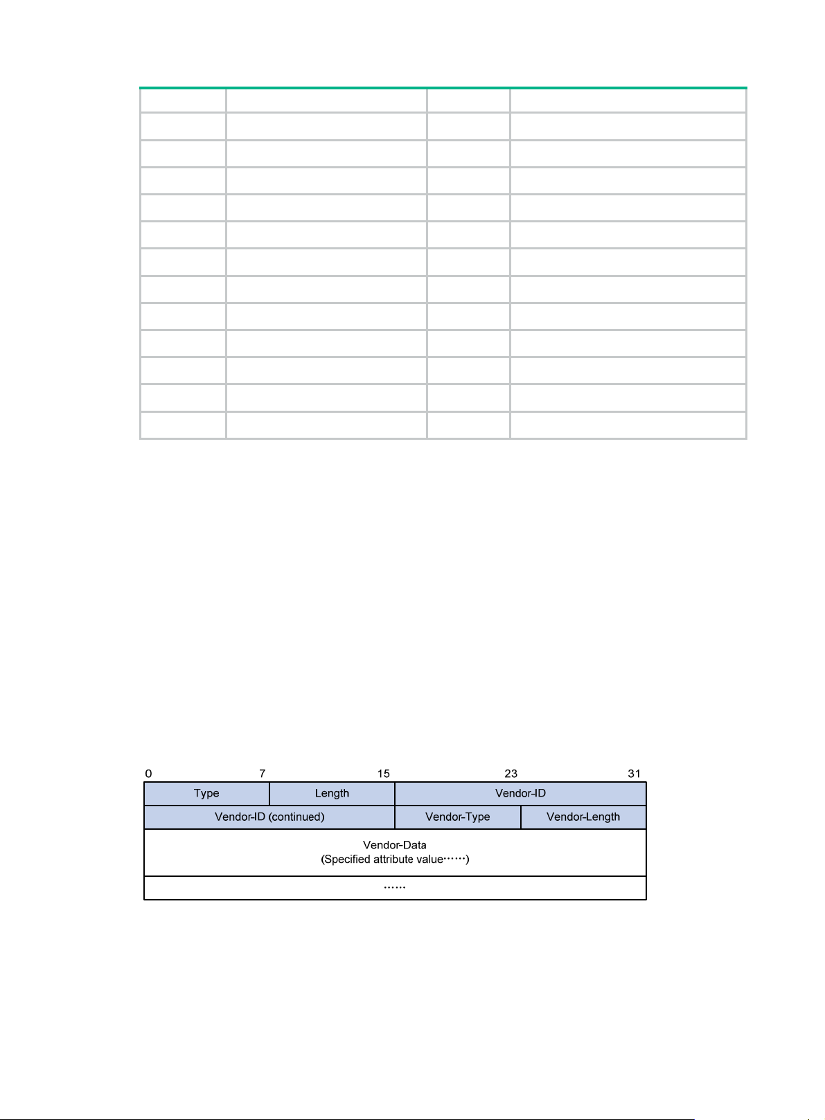
Extended RADIUS attributes
The RADIUS protocol features excellent extensibility. The Vendor-Specific attribute (attribute 26)
allows a vendor to define extended attributes. The extended attributes implement functions that the
standard RADIUS protocol does not provide.
A vendor can encapsulate multiple subattributes in the TL V format in attribute 26 to provide exte nded
functions. As shown in Figure 5, a
subattribute encapsulated in attribute 26 consists of the following
parts:
• Vendor-ID—ID of the vendor. The most significant byte is 0. The other three bytes contains a
code compliant to RFC 1700.
• Vendor-Type—Type of the subattribute.
• Vendor-Length—Length of the subattribute.
• Vendor-Data—Contents of the subattribute.
For more information about the proprietary RADIUS subattributes of HPE, see "HPE proprietary
RADIUS sub
attributes."
Figure 5 Format of attribute 26
HWTACACS
HW Terminal Access Controller Access Control System (HWTACACS) is an enhanced security
protocol based on T ACACS (RFC 1492 ). HWT ACACS is similar to RADIUS, and uses a client/server
model for information exchange between the NAS and the HWTACACS server.
6
Page 15

HWTACACS typically provides AAA services for PPP, VPDN, and terminal users. In a typical
HWT ACA CS scenario, terminal users need to log in to the NAS. Working as the HWTACACS client,
the NAS sends users' usernames and passwords to the HWTACACS server for authentication. After
passing authentication and obtaining authorized rights, a user logs in to the device and performs
operations. The HWTACACS server records the operations that each user performs.
Differences between HWTACACS and RADIUS
HWTACACS and RADIUS have many features in common, such as using a client/server model,
using shared keys for data encryption, and providing flexibility and scalability. Table 3 lists the
ry differences between HWTACACS and RADIUS.
prima
Table 3 Primary differences between HWTACACS and RADIUS
HWTACACS RADIUS
Uses TCP, which provides reliable network
transmission.
Uses UDP, which provides high transport efficiency.
Encrypts the entire packet except for the
HWTACACS header.
Protocol packets are complicated and authorization
is independent of authentication. Authentication and
authorization can be deployed on different
HWTACACS servers.
Supports authorization of configuration commands.
Access to commands depends on both the user's
roles and authorization. A user can use only
commands that are permitted by the user roles and
authorized by the HWTACACS server.
Basic HWTACACS packet exchange process
Figure 6 describes how HWT ACACS perf orms user authentication, a uthorization, and accounting for
a Telnet user .
Encrypts only the user password field in an
authentication packet.
Protocol packets are simple and the authorization
process is combined with the authentication
process.
Does not support authorization of configuration
commands. Access to commands solely depends on
the user's roles. For more information about user
roles, see Fundamentals Configuration Guide.
7
Page 16

Figure 6 Basic HWTACACS packet exchange process for a Telnet user
Host HWTACACS client HWTACACS server
1) The user tries to log in
2) Start-authentication packet
3) Authentication response requesting the username
4) Request for username
5) The user enters the username
6) Continue-authentication packet with the username
7) Authentication response requesting the password
8) Request for password
9) The user enters the password
10) Continue-authentication packet with the password
11) Response indicating successful authentication
12) User authorization request packet
13) Response indicating successful authorization
14) The user logs in successfully
15) Start-accounting request
16) Response indicating the start of accounting
17) The user logs off
18) Stop-accounting request
19) Stop-accounting response
HWTACACS operates using the following workflow:
1. A Telnet user sends an access request to the HWTACACS client.
2. The HWTACACS client sends a start-authentication packet to the HWTACACS server when it
receives the request.
3. The HWTACACS server sends back an authentication response to request the username.
4. Upon receiving the response, the HWTACACS client asks the user for the username.
5. The user enters the username.
6. After receiving the username from the user, the HWTACACS client sends the server a
continue-authentication packet that includes the username.
7. The HWTACACS server sends back an authentication response to request the login password.
8. Upon receipt of the response, the HWTACACS client prompts the user for the login password.
9. The user enters the password.
8
Page 17
10. After receiving the login password, the HWTACACS client sends the HWTACACS serv er a
continue-authentication packet that includes the login password.
11. If the authentication succeeds, the HWTACACS server sends back an authenti cation response
to indicate that the user has passed authentication.
12. The HWTACACS client sends a user authorization request packet to the HWTACACS server.
13. If the authorization succeeds, the HWTACACS server sends back an authorization response,
indicating that the user is now authorized.
14. Knowing that the user is now authorized, the HWTACACS client pushes its CLI to the user and
permits the user to log in.
15. The HWTACACS client sends a start-accounting request to the HWTACACS server.
16. The HWTACACS server sends back an accounting response, indi cating that it has received the
start-accounting request.
17. The user logs off.
18. The HWTACACS client sends a stop-accounting request to the HWTACACS server.
19. The HWTACACS server sends back a stop-accounting response, indicating that the
stop-accounting request has been received.
AAA implementation on the device
This section describes AAA user mana gement and methods.
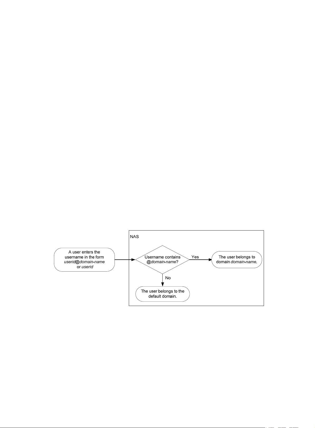
User management based on ISP domains and user access types
AAA manages users based on the users' ISP domains and access types.
On a NAS, each user belongs to one ISP domain. The NAS determines the ISP domain to which a
user belongs based on the username entered by the user at login.
Figure 7 Determining the ISP domain for a user by username
AAA manages use rs in the same ISP domain based on the users' access types. The device supports
AAA for login users. Login users include SSH, Telnet, FTP, and terminal users who log in to the
device. Terminal users can access through a console port.
AAA methods
AAA supports configuring different authentication, authorization, and accounting methods for
different types of users in an ISP domain. The N AS determines the ISP domain and access type of a
user, and uses the methods configured for the access type in the domain to control the user's
access.
AAA also supports configuring a set of default methods for an ISP domain. These default methods
are applied to users for whom no AAA method s are configured.
The device supports the following authentication methods:
9
Page 18

• No authentication—This method trusts all users and does not perform authentication. For
security purposes, do not use this method.
• Local authentication—The NAS authenticates users by itself, based on the locally configured
user information including the usernames, passwords, and attributes. Local authentication
allows high speed and low cost, but the amount of information that can be stored is limited by
the size of the storage space.
• Remote authentication—The NAS works with a RADIUS or HW TACACS server to
authenticate users. The server manages user information in a centralized manner. Remote
authentication provides high capacity, reliable, and centralized authentication services for
multiple NASs. You can configure backup methods to be used when the remote server is not
available.
The device supports the following authorization methods:
• No authorization—The NAS performs no authorization exchange. After passing
authentication, users can access the network, except FTP, SFTP , and SCP u sers. When an FTP,
SFTP, or SCP user passes authentication, the working directory is set to the root directory of the
NAS, but the user cannot access this directory.
• Local authorization—The NAS performs authorization according to the user attributes locally
configured for users.
• Remote authorization—The NAS works with a RADIUS or HWTACACS server to authorize
users. RADIUS authorization is bound with RADIUS authentication. RADIUS a uthorization can
work only after RADIUS authentication is successful, and the authorization information is
included in the Access-Accept packet. HWTACACS authorization is separate from
HWTACACS authentication, and the authorization information is included in the authorizatio n
response after successful authentication. You can configure backup methods to be used when
the remote server is not available.
The device supports the following accounting methods:
• No accounting—The NAS does not perform accounting for the users.
• Local accounting—Local accounting is implemented on the NAS. It counts and controls the
number of concurrent users who use the same local user account, but does not provide
statistics for charging.
• Remote accounting—The NAS works with a RADIUS server or HWTACACS server for
accounting. You can configure ba ckup methods to be used when the remote server is not
available.
In addition, the device provides the following login services to enhance device security:
• Command authorization—Enables the NAS to let the authorization server d etermine whether
a command entered by a login user is permitted. Login users can execute only commands
permitted by the authorization server. Fo r more info rm ation about command auth orization, see
Fundamentals Configuration Guide.
• Command accounting—When command authorization is disabled, command accounting
enables the accounting server to record all valid commands executed on the device. When
command authorization is enabled, command accounting enables the accounting server to
record all authorized commands. For more information about command accounting, see
Fundamentals Configuration Guide.
• User role authentication—Authenticates each user who wants to obtain a temporary user role
without logging out or getting disconnected. For more information about temporary user role
authorization, see Fundamentals Configuration Guide.
Protocols and standards
• RFC 2865, Remote Authentication Dial In User Service (RADIUS)
• RFC 2866, RADIUS Accounting
10
Page 19

• RFC 2867, RADIUS Accounting Modifications for Tunnel Protocol Support
• RFC 2868, RADIUS Attributes for Tunnel Protocol Support
• RFC 2869, RADIUS Extensions
• RFC 1492, An Access Control Protocol, Sometimes Called T ACACS
RADIUS attributes
Commonly used standard RADIUS attributes
No. Attribute Description
1 User-Name Name of the user to be authenticated.
2 User-Password
3 CHAP-Password
4 NAS-IP-Address
5 NAS-Port Physical port of the NAS that the user accesses.
6 Service-Type
7 Framed-Protocol Encapsulation protocol for framed access.
8 Framed-IP-Address IP address assigned to the user.
11 Filter-ID Name of the filter list.
12 Framed-MTU
14 Login-IP-Host IP address of the NAS interface that the user accesses.
15 Login-Service Type of the service that the user uses for login.
18 Reply-Message
User password for PAP authentication, only present in Access-Request
packets when PAP authentication is used.
Digest of the user password for CHAP authentication, only present in
Access-Request packets when CHAP authentication is used.
IP address for the server to use to identify the client. Typically, a client is
identified by the IP address of its access interface. This attribute is only
present in Access-Request packets.
Type of service that the user has requested or type of service to be
provided.
MTU for the data link between the user and NAS. For example, this
attribute can be used to define the maximum size of EAP packets allowed
to be processed in 802.1X EAP authentication.
Text to be displayed to the user, which can be used by the server to
communicate information, for example, the reason of the authentication
failure.
Vendor-specific proprietary attribute. A packet can contain one or more
26 Vendor-Specific
27 Session-Timeout Maximum service duration for the user before termination of the session.
28 Idle-Timeout
31 Calling-Station-Id
32 NAS-Identifier Identification that the NAS uses to identify itself to the RADIUS server.
40 Acct-Status-Type
proprietary attributes, each of which can contain one or more
subattributes.
Maximum idle time permitted for the user before termination of the
session.
User identification that the NAS sends to the server. For the LAN access
service provided by an HPE device, this attribute includes the MAC
address of the user in the format HHHH-HHHH-HHHH.
Type of the Accounting-Request packet. Possible values include:
• 1—Start.
• 2—Stop.
• 3—Interim-Update.
• 4—Reset-Charge.
11
Page 20

No. Attribute Description
• 7—Accounting-On. (Defined in the 3rd Generation Partnership
Project.)
• 8—Accounting-Off. (Defined in the 3rd Generation Partnership
Project.)
• 9 to 14—Reserved for tunnel accounting.
• 15—Reserved for failed.
Authentication method used by the user. Possible values include:
45 Acct-Authentic
• 1—RADIUS.
• 2—Local.
• 3—Remote.
60 CHAP-Challenge
61 NAS-Port-Type
79 EAP-Message
80
87 NAS-Port-Id String for describing the port of the NAS that is authenticating the user.
Message-Authenticato
r
CHAP challenge generated by the NAS for MD5 calculation during CHAP
authentication.
Type of the physical port of the NAS that is authenticating the user.
Possible values include:
• 15—Ethernet.
• 16—Any type of ADSL.
• 17—Cable. (With cable for cable TV.)
• 19—WLAN-IEEE 802.11.
• 201—VLAN.
• 202—ATM.
If the port is an ATM or Ethernet one and VLANs are implemented on it,
the value of this attribute is 201.
Used to encapsulate EAP packets to allow RADIUS to support EAP
authentication.
Used for authentication and verification of authentication packets to
prevent spoofing Access-Requests. This attribute is present when EAP
authentication is used.
HPE proprietary RADIUS subattributes
No. Subattribute Description
1 Input-Peak-Rate Peak rate in the direction from the user to the NAS, in bps.
2 Input-Average-Rate Average rate in the direction from the user to the NAS, in bps.
3 Input-Basic-Rate Basic rate in the direction from the user to the NAS, in bps.
4 Output-Peak-Rate Peak rate in the direction from the NAS to the user, in bps.
5 Output-Average-Rate Average rate in the direction from the NAS to the user, in bp s.
6 Output-Basic-Rate Basic rate in the direction from the NAS to the user, in bps.
15 Remanent_Volume
20 Command
Total remaining available traffic for the connection, in different units for
different server types.
Operation for the session, used for session control. Possible values
include:
• 1—Trigger-Request.
• 2—Terminate-Request.
• 3—SetPolicy.
• 4—Result.
• 5—PortalClear.
12
Page 21

No. Subattribute Description
Identification for retransmitted packets. For retransmitted packets from
the same session, this attribute must be the same value. For
retransmitted packets from different sessions, this attribute does not
24 Control_Identifier
have to be the same value. The client response of a retransmitted
packet must also include this attribute and the value of this attribute
must be the same.
For Accounting-Request packets of the start, stop, and interim update
types, the Control_Identifier attribute does not take effect.
25 Result_Code
Result of the Trigger-Request or SetPolicy operation, zero for success
and any other value for failure.
26 Connect_ID Index of the user connection.
FTP, SFTP, or SCP user working directory.
28 Ftp_Directory
When the RADIUS client acts as the FTP, SFTP, or SCP server, this
attribute is used to set the working directory for an FTP, SFTP, or SCP
user on the RADIUS client.
29 Exec_Privilege EXEC user priority.
59 NAS_Startup_Timestamp
Startup time of the NAS in seconds, which is represented by the time
elapsed after 00:00:00 on Jan. 1, 1970 (UTC).
User IP address and MAC address included in authentication and
60 Ip_Host_Addr
accounting requests, in the format A.B.C.D hh:hh:hh:hh:hh:hh. A
space is required between the IP address and the MAC address.
61 User_Notify
Information that must be sent from the server to the client
transparently.
Hash value assigned after an 802.1X user passes authentication,
which is a 32-byte string. This attribute is stored in the user list on the
62 User_HeartBeat
NAS and verifies the handshake packets from the 802.1X user. This
attribute only exists in Access-Accept and Accounting-Request
packets.
User groups assigned after the SSL VPN user passes authentication.
140 User_Group
A user can belong to multiple user groups that are separated by
semicolons. This attribute is used to work with the SSL VPN device.
141 Security_Level
Security level assigned after the SSL VPN user passes security
authentication.
201 Input-Interval-Octets Number of bytes input within a real-time accounting interval.
202 Output-Interval-Octets Number of bytes output within a real-time accounting interval.
203 Input-Interval-Packets
204 Output-Interval-Packets
205 Input-Interval-Gigawords
206
Output-Interval-Gigawords Amount of bytes output within an accounting interval, in units of 4G
Number of packets input within an accounting interval in the unit set on
the NAS.
Number of packets output within an accounting interval in the unit set
on the NAS.
Amount of bytes input within an accounting interval, in units of 4G
bytes.
bytes.
207 Backup-NAS-IP Backup source IP address for sending RADIUS packets.
255 Product_ID Product name.
13
Page 22
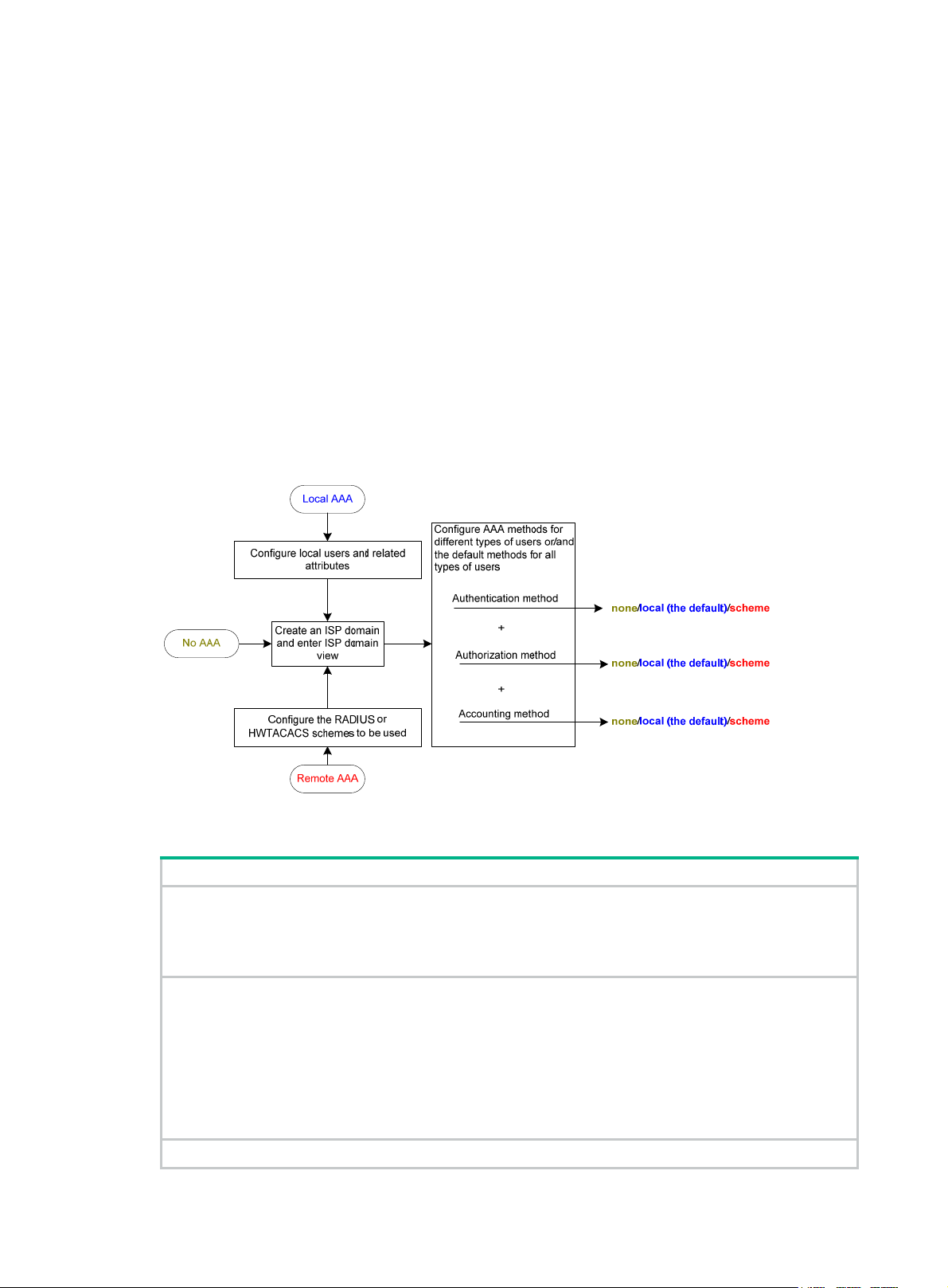
FIPS compliance
The device supports the FIPS mode that complies with NIST FIPS 140-2 requirements. Support for
features, commands, and parameters might differ in FIPS mode (see "Configuring FIPS") and
non-FIPS mode.
AAA configuration considerations and task list
To configure AAA, complete the following tasks on the NAS:
1. Configure the required AAA schemes:
{ Local authentication—Configure local users and the related attributes, including the
usernames and passwords, for the users to be authenticated.
{ Remote authentication—Configure the required RADIUS and HWTACACS schemes.
2. Configure AAA methods for the users' ISP domains. To use remote AAA methods, you must
specify the configured RADIUS or HWTACACS schemes.
Figure 8 AAA configuration procedure
To configure AAA, perform the following tasks:
Tasks at a glance
(Required.) Perform at least one of the following tasks to configure local users or AAA schemes:
• Configuring local users
• Configuring RADIUS schemes
• Configuring HWTACACS schemes
(Required.) Configure AAA methods for ISP domains:
1. (Required.) Creating an ISP domain
2. (Optiona
3. (Req
and accounting methods for the ISP domain:
{ Configuring authentication methods for an ISP domain
{ Configuring authorization methods for an ISP domain
{ Configuring accounting methods for an ISP domain
(Optional.) Enabling the session-control feature
l.) Setting the ISP domain status
uired.) Perform at least one of the following tasks to configure AAA authentication, authorization,
14
Page 23

Tasks at a glance
(Optional.) Setting the maximum number of concurrent login users
Configuring AAA schemes
This section includes information on configuring local users, RADIUS schemes, and HWTACACS
schemes.
Configuring local users
To implement local authentication, authorization, and accounting, create local users and configure
user attributes on the device. The local users and attributes are stored in the local user database on
the device. A local user is u niquely identified by the combination of a username and a user type. The
device supports only device management users who log in to the device for device management.
The following local user attributes are configurable:
• Service type—Services that the user can use. Lo cal authentication checks the service types of
a local user. If none of the service types is available, the user cannot pass authentication.
Service types include FTP, SSH, Telnet, and terminal.
• User state—Whether or not a local user can request network services. There are two user
states: active and blocked. A user in active state can request netwo rk services, but a user in
blocked state cannot.
• Upper limit of concurrent logins using the same user name—Maximum number of users
who can concurrently access the device by using the same user name. When the number
reaches the upper limit, no more local users can access the device by using the user name.
• User group—Each local user belongs to a lo cal use r group and h as all attribut es of the g roup.
The attributes include the password control attributes and authorization attributes. For more
information about local user group, see "Configuring user group attributes."
• Authorization attributes—Authorization attributes indicate the user's rights after it passes
local authentication. Authorization attribut es include the ACL, idle cut feature, user role, VLAN,
and FTP/SFTP/SCP working directory. For support information about authori zation attributes,
see "Configuring local user attributes."
ure the authorization attributes based on the service type of local users.
Config
You can configure an authorization attribute in user group view or local user view. The setting of
an authorization attribute in local user view takes precedence over the attribute setting in user
group view.
{ The attribute configured in user group view applies to all local users in the user group.
{ The attribute configured in local user view applies only to the local user.
• Password control attributes—Password control attributes help control password security for
device management users. Password control attributes include password aging time, minimum
password length, password composition checking, password complexity checking, and login
attempt limit.
You can configure a password control attribute in system view, user group view, or local user
view. A password control attribute with a smaller effective range has a higher priority. For more
information about password management and global password configuration, see "Configuring
password control."
15
Page 24

Local user configuration task list
Tasks at a glance
(Required.) Configuring local user attributes
(Optional.) Configuring user group attributes
(Optional.) Displaying and maintaining local users and local user groups
Configuring local user attributes
When you configure local user attributes, follow these guidelines:
• When you use the password-control enable command to globally enable the password
control feature, local user passwords are not displayed.
• You can configure authorization attributes and password control attributes in local user view or
user group view. The setting in local user view takes precedence over the setting in user group
view.
• Configure authorization attributes according to the application environments and purposes.
Support for authorization attributes depends on the service types of users.
{ For Telnet and terminal users, only the authorization attributes idle-cut and user-role are
effective.
{ For SSH users, only the authorization attributes idle-cut, user-role, and work-directory
are effective.
{ For FTP users, only the authorization attributes user-role and work-directory are effective.
{ For other types of local users, no authorization attribute takes effect.
To configure local user attributes:
Step Command Remarks
1. Enter system view.
2. Add a local user and enter
local user view.
3. (Optional.) Configure a
password for the local
user.
4. Assign services to the
local user.
5. (Optional.) Place the local
user to the active or
blocked state.
system-view
local-user
manage
]
user-name [
class
• In non-FIPS mode:
password [ { hash | simple }
password ]
• In FIPS mode:
password
• In non-FIPS mode:
service-type { ftp | { ssh |
telnet | terminal } * }
• In FIPS mode:
service-type { ssh | terminal }
*
state { active | block
}
N/A
By default, no local user exists.
The password is encrypted with the
hash algorithm and saved in
ciphertext.
In non-FIPS mode, a
non-password-protected user
passes authentication if the user
provides the correct username and
passes attribute checks. To
enhance security, configure a
password for each local user.
In FIPS mode, only
password-protected users can pass
authentication.
By default, no service is authorized
to a local user.
By default, a created local user is in
active state and can request
network services.
6. (Optional.) Set the upper
access-limit
max-user-number
16
By default, the number of concurrent
Page 25

Step Command Remarks
limit of concurrent logins
using the local user
name.
7. (Optional.) Configure
authorization attributes
for the local user.
8. (Optional.) Configure
password control
attributes for the local
user.
9. (Optional.) Assign the
local user to a user group.
authorization-attribute
acl-number |
user-role
work-directory
• Set the password aging time:
password-control aging
aging-time
• Set the minimum password
length:
password-control length
length
• Configure the password
composition policy:
password-control
composition type-number
type-number [ type-length
type-length ]
• Configure the password
complexity checking policy:
password-control
complexity { same-character
| user-name } check
• Configure the maximum login
attempts and the action to take
if there is a login failure:
password-control
login-attempt login-times
[ exceed { lock | lock-time
time | unlock } ]
group
idle-cut
role-name |
directory-name } *
group-name
{
minute |
vlan
acl
vlan-id |
logins is not limited for the local
user.
This command takes effect only
when local accounting is configured
for the local user. It does not apply to
FTP, SFTP, or SCP users, who do
not support accounting.
The following default settings apply:
• FTP, SFTP, and SCP users have
the root directory of the NAS set
as the working directory.
However, the users do not have
permission to access the root
directory.
• The network-operator user role
is assigned to local users that
are created by a network-admin
or level-15 user on the default
MDC.
• The mdc-operator user role is
assigned to local users that are
created by an mdc-admin or
level-15 user on a non-default
MDC.
Optional.
By default, the local user uses
password control attributes of the
user group to which the local user
belongs.
By default, a local user belongs to
the default user group
system
.
Configuring user group attributes
User groups simplify local user configuration and management. A user group contains a group of
local users and has a set of local user attributes. You can configure local user attributes for a user
group to implement centralized user attributes management for the local users in the group. Local
user attributes that are manageable include authorization attributes.
17
Page 26

By default, every new local user belongs to the default user group system and has all attributes of
the group. To assign a local user to a different user group, use the group command in local user
view.
To configure user group attributes:
Step Command Remarks
1. Enter system view.
system-view
N/A
2. Create a user group and
enter user group view.
3. Configure authorization
attributes for the user
group.
4. (Optional.) Configure
password control attributes
for the user group.
user-group
authorization-attribute
acl-number |
vlan-id |
directory-name } *
• Set the password aging time:
password-control aging
aging-time
• Set the minimum password
length:
password-control length length
• Configure the password
composition policy:
password-control composition
type-number type-number
[ type-length type-length ]
• Configure the password
complexity checking policy:
password-control complexity
{ same-character | user-name }
check
• Configure the maximum login
attempts and the action to take
for login failures:
password-control
login-attempt login-times
[ exceed { lock | lock-time time |
unlock } ]
group-name
idle-cut
work-directory
acl
{
minute |
vlan
By default, there is a
system-defined user group
system
named
default user group.
By default, no authorization
attribute is configured for a user
group.
Optional.
By default, the user group uses
the global password control
settings. For more information,
see "Configuring password
control."
, which is the
Displaying and maintaining local users and local user groups
Execute display commands in any view .
Task Command
Display the local user
configuration and online user
statistics.
Display the user group
configuration.
display local-user
service-type
user-name
display user-group
{
user-name |
class manage
[
ftp
ssh
|
[ group-name ]
telnet
|
vlan
|
vlan-id ]
Configuring RADIUS schemes
A RADIUS scheme specifies the RADIUS serve rs that the device can wo rk with and defin es a set of
parameters. The device uses the parameters to exchange information with the RADIUS servers,
including the IP addresses of the servers, UDP port numbers, shared keys, and server types.
18
idle-cut
|
terminal
} |
disable
{
state
active
{
enable
|
block
|
} |
} |
Page 27

Configuration task list
Tasks at a glance
(Required.) Creating a RADIUS scheme
(Required.) Specifying the RADIUS authentication servers
(Optional.) Specifying the RADIUS accounting servers and the relevant parameters
(Optional.) Specifying the shared keys for secure RADIUS communication
(Optional.) Specifying a VPN for the scheme
(Optional.) Setting the username format and traffic statistics units
(Optional.) Setting the maximum number of RADIUS request transmission attempts
(Optional.) Setting the status of RADIUS servers
(Optional.) Specifying the source IP address for outgoing RADIUS packets
(Optional.) Setting RADIUS timers
(Optional.) Configuring the accounting-on feature
(Optional.) Configuring the IP addresses of the security policy servers
(Optional.) Configuring the Login-Service attribute check method for SSH, FTP, and terminal us ers
(Optional.) Enabling SNMP notifications for RADIUS
(Optional.) Displaying and maintaining RADIUS
Creating a RADIUS scheme
Create a RADIUS scheme before performing any other RADIUS configurations. You can configure a
maximum of 16 RADIUS schemes. A RADIUS scheme can be used by multiple ISP domains.
To create a RADIUS scheme:
Step Command Remarks
1. Enter system view.
2. Create a RADIUS scheme
and enter RADIUS scheme
view.
system-view
radius scheme
radius-scheme-name
Specifying the RADIUS authentication servers
A RADIUS authentication server completes authentication and authorization together, because
authorization information is piggybacked in authentication responses sent to RADIUS clients.
You can specify one primary authentication server and a maximum of 16 secondary authentication
servers for a RADIUS scheme. When the primary server is not available, the device searches for the
secondary servers in the order they are configured. The first secondary server in active state i s used
for communication.
If redundancy is not required, specify only the primary server. A RADIUS authentication server can
act as the primary authentication server for one scheme and a secondary authentication server for
another scheme at the same time.
N/A
By default, no RADIUS scheme is
defined.
To specify RADIUS authentication servers for a RADIUS scheme:
Step Command Remarks
1. Enter system view.
system-view
N/A
19
Page 28

Step Command Remarks
2. Enter RADIUS scheme
view.
3. Specify RADIUS
authentication servers.
radius scheme
• Specify the primary RADIUS
authentication server:
primary authentication
{ host-name | ipv4-address }
[ port-number | key { cipher |
simple } string | vpn-instance
vpn-instance-name ] *
• Specify a secondary RA DIUS
authentication server:
secondary authentication
{ host-name | ipv4-address }
[ port-number | key { cipher |
simple } string | vpn-instance
vpn-instance-name ] *
radius-scheme-name N/A
By default, no authentication
server is specified.
Two authentication servers in a
scheme, primary or secondary,
cannot have the same
combination of hostname, IP
address, port number, and VPN.
Specifying the RADIUS accounting servers and the relevant parameters
Y ou can specify one primary accounting server and a maximum of 16 se condary accountin g servers
for a RADIUS scheme. When the primary server is not available, the device searches for the
secondary servers in the order they are configured. The first secondary server in active state i s used
for communication.
If redundancy is not required, specify only the primary server. A RADIUS accounting server can act
as the primary accounting server for one scheme and a secondary accounting server for another
scheme at the same time.
The device sends a stop-accounting request to the accounting server in the following situations:
• The device receives a connection teardown request from a host.
• The device receives a connection teardown command from an administrator.
When the maximum number of real-time accounting attempts is reached, the device disconnects
users who have no accounting responses.
RADIUS does not support accounting for FTP, SFTP, and SCP users.
To specify RADIUS accounting servers and the relevant parameters for a RADIUS scheme:
Step Command Remarks
1. Enter system view.
2. Enter RADIUS scheme view.
3. Specify RADIUS accounting
servers.
4. (Optional.) Set the maximum
number of real-time
system-view
radius scheme
• Specify the primary RADIUS
accounting server:
primary accounting { host-name |
ipv4-address } [ port-number | key
{ cipher | simple } string |
vpn-instance vpn-instance-name ]
*
• Specify a secondary RA DIUS
accounting server:
secondary accounting
{ host-name | ipv4-address }
[ port-number | key { cipher |
simple } string | vpn-instance
vpn-instance-name ] *
retry realtime-accounting
radius-scheme-name N/A
retry-times The default setting is 5.
N/A
By default, no accounting
server is specified.
Two accounting servers in a
scheme, primary or
secondary, cannot have the
same combination of
hostname, IP address, port
number, and VPN.
20
Page 29

Step Command Remarks
accounting attempts.
Specifying the shared keys for secure RADIUS communication
The RADIUS client and server use the MD5 algorithm and shared keys to generate the Authenticator
value for packet authentication and user password encryption. The client and server must use the
same key for each type of communication.
A key configured in this task is for all servers of the same type (accounting or authentication) in the
scheme. The key has a lower priority than a key configured individually for a RADIUS server.
To specify a shared key for secure RADIUS communication:
Step Command Remarks
1. Enter system view.
system-view
N/A
2. Enter RADIUS scheme view.
3. Specify a shared key for
secure RADIUS
communication.
Specifying a VPN for the scheme
The VPN specified for a RADIUS scheme applies to all authentication and acco unting servers in that
scheme. If a VPN is also configured for an individual RADIUS server, the VPN specified for the
RADIUS scheme does not take effect on that server.
To specify a VPN for a scheme:
Step Command Remarks
1. Enter system view.
2. Enter RADIUS scheme view.
3. Specify a VPN for the RADIUS
scheme.
radius scheme
radius-scheme-name
key
accounting
{
authentication
simple
} string
system-view
radius scheme
radius-scheme-name
vpn-instance
|
cipher
} {
vpn-instance-name
N/A
By default, no shared key is
specified.
|
The shared key configured on the
device must be the same as the
shared key configured on the
RADIUS server.
N/A
N/A
By default, a RADIUS
scheme belongs to the public
network.
Setting the username format and traffic statistics units
A username is in the userid@isp-name format, where the isp-name argument represents the user's
ISP domain name. By default, the ISP domain name is included in a username. However, older
RADIUS servers might not recognize usernames that contain the ISP domain names. In this case,
you can configure the device to remove the domain name of each username to be sent.
If two or more ISP domains use the same RADIUS scheme, configure the RA DIUS scheme to keep
the ISP domain name in usernames for domain identification.
The device reports online user traffic statistics in accounting packets. The traf fic measurement units
are configurable, but they must be the same as the traffic measurement units configured on the
RADIUS accounting servers.
To set the username format and the traf fic statistics units for a RADIUS scheme:
21
Page 30

Step Command Remarks
1. Enter system view.
system-view
N/A
2. Enter RADIUS scheme view.
3. Set the format for usernames
sent to the RADIUS servers.
4. (Optional.) Set the data flow
and packet measurement
units for traffic statistics.
radius scheme
radius-scheme-name
user-name-format
keep-original
{
without-domain
data-flow-format { data
giga-byte | kilo-byte |
mega-byte } | packet
giga-packet | kilo-packet |
{
mega-packet | one-packet
with-domain
|
}
{
|
byte |
} }*
N/A
By default, the ISP domain name
is included in a username.
By default, traffic is counted in
bytes and packets.
Setting the maximum number of RADIUS request transmission attempts
RADIUS uses UDP packets to transfer data. Because UDP communication is not reliable, RADIUS
uses a retransmission mechanism to improve reliability. A RADIUS request is retransmitted if the
NAS does not receive a server response for the request within the response timeout timer. For more
information about the RADIUS server response timeout timer, see "Setting RADIUS timers."
ou can set the maximum number for the NAS to retransmit a RADIUS request to the same server.
Y
When the maximum number is reached, the NAS tries to communicate with other RADIUS servers in
active state. If no other servers are in active state at the time, the NAS considers the authentication
or accounting attempt a failure.
To set the maximum number of RADIUS request tran smission attempts:
Step Command Remarks
1. Enter system view.
system-view
N/A
2. Enter RADIUS scheme view.
3. Set the maximum number of
RADIUS request transmission
attempts.
Setting the status of RADIUS servers
T o control the RADIUS servers with which the device communicates whe n the current servers are no
longer available, set the status of RADIUS servers to blocked or active. You can specify one primary
RADIUS server and multiple secondary RADIUS servers. The secondary servers act as the backup
of the primary server. The device chooses servers based on the following rules:
• When the primary server is in active state, the device communicates with the primary server.
• If the primary server fails, the device performs the following operations:
{ Changes the server status to blocked.
{ Starts a quiet timer for the server.
{ Tries to communicate with a secondary server in active state that has the highest priority.
• If the secondary server is unreachable, the device performs the following operations:
{ Changes the server status to blocked.
{ Starts a quiet timer for the server.
{ Tries to communicate with the next secondary server in active state that has the highest
priority.
radius scheme
radius-scheme-name
retry
retry-times The default setting is 3.
N/A
22
Page 31

• The search process continues until the device finds an available secondary server or has
checked all secondary servers in active state. If no server is available, the device considers the
authentication or accounting attempt a failure.
• When the quiet timer of a server expires or you manually set the server to the active state, the
status of the server changes back to active. The device does not check the server again during
the authentication or accounting process.
• When you remove a server in use, communication with the server times out. The device look s
for a server in active state by first checking the primary server, and then checking secondary
servers in the order they are configured.
• When the primary server and secondary servers are all in blocked state, the device tries to
communicate with the primary server.
• When one or more servers are in active state, the device tries to communicate with these active
servers only, even if the servers are unavailable.
• When the status of a RADIUS server changes automatically, the device changes the status of
this server accordingly in all RADIUS schemes in which this server is specified.
By default, the device sets the status of all RADIUS servers to active. However, in some situations,
you must change the status of a server. For example, if a server fails, you can change the status of
the server to blocked to avoid communication attempts to the server.
To set the status of RADIUS servers:
Step Command Remarks
1. Enter system view.
2. Enter RADIUS scheme
view.
3. Set the RADIUS server
status.
system-view
radius scheme
• Set the status of the primary
RADIUS authentication server:
state primary authentication
{ active | block }
• Set the status of the primary
RADIUS accounting server:
state primary accounting { active |
block }
• Set the status of a secondary
RADIUS authentication server:
state secondary authentication
[ { host-name | ipv4-address }
[ port-number | vpn-instance
vpn-instance-name ] * ] { active |
block }
• Set the status of a secondary
RADIUS accounting server:
state secondary accounting
[ { host-name | ipv4-address }
[ port-number | vpn-instance
vpn-instance-name ] * ] { active |
block }
radius-scheme-name N/A
N/A
By default, every server
specified in a RADIUS
scheme is in active state.
The configured server status
cannot be saved to any
configuration file, and can
only be viewed by using the
display radius scheme
command. After the device
restarts, all servers are
restored to the active state.
Specifying the source IP address for outgoing RADIUS packets
The source IP address of RADIUS packets that a NAS sends must match the IP address of the NAS
configured on the RADIUS server. A RADIUS server identifies a NAS by its IP address. Upon
receiving a RADIUS packet, a RADIUS server checks whether the source IP address of the packet is
the IP address of a managed NAS.
• If the source IP address of the packet is the IP address of a managed NAS, the server
processes the packet.
23
Page 32

• If the source IP address of the packet is not the IP address of a managed NAS, the server drops
the packet.
The source address of outgoing RADIUS packets is typically the IP address of an egress interface on
the NAS to communicate with the RADIUS server. However, in some situations, you must change
the source IP address. For example, when VRRP is configured for stateful failover, configure the
virtual IP address of the uplink VRRP group as the source IP address.
You can specify a source IP address for outgoing RADIUS packets in RADIUS scheme view or in
system view.
• The IP address specified in RADIUS scheme view applies only to one RADIUS scheme.
• The IP address specified in system vie w applies to all RADIUS schemes whose servers a re in a
VPN or the public network.
Before sending a RADIUS packet, the NAS selects a source IP addre s s in the following order:
1. The source IP address specified for the RADIUS scheme.
2. The source IP address specified in system view for the VPN or public network, depending on
where the RADIUS server resides.
3. The IP address of the outbound interface specified by the route.
To specify a source IP address for all RADIUS sche mes in a VPN or the public network:
Step Command Remarks
1. Enter system view.
system-view
N/A
2. Specify a source IP address
for outgoing RADIUS
packets.
To specify a source IP address for a RADIUS sche me:
Step Command Remarks
1. Enter system view.
2. Enter RADIUS scheme view.
3. Specify a source IP address
for outgoing RADIUS
packets.
Setting RADIUS timers
The device uses the following types of timers to control communication with a RADIUS server:
• Server response timeout timer (response-timeout)—Defines the RADIUS request
retransmission interval. The timer starts immediately after a RADIUS request is sent. If the
device does not receive a response from the RADIUS server before the timer expires, it
resends the request.
• Server quiet timer (quiet)—Defines the duration to keep an unreachable server in blocked
state. If one server is not reachable, the device changes the server status to blocked, starts this
timer for the server, and tries to communicate with another server in active state. After the
server quiet timer expires, the device changes the status of the server back to active.
• Real-time accounting timer (realtime-accounting)—Defines the interval at which the device
sends real-time accounting packets to the RADIUS accounting server for online users.
radius nas-ip
vpn-instance
[
vpn-instance-name ]
system-view
radius scheme
radius-scheme-name
nas-ip
ipv4-address
ipv4-address
By default, the IP address of the
RADIUS packet outbound
interface is used as the source IP
address.
N/A
N/A
By default, the source IP address
specified by the
command in system view is used.
If the source IP address is not
specified, the IP address of the
outbound interface is used.
radius nas-ip
24
Page 33

When you set RADIUS timers, follow these guidelines:
• Consider the number of secondary servers when you configure the maximum number of
RADIUS packet transmission attempts and the RADIUS server response timeout timer. If the
RADIUS scheme includes many secondary servers, the retransmission process might be too
long and the client connection in the access module, such as Telnet, can time out.
• When the client connections have a short timeout period, a large number of se condary servers
can cause the initial authentication or accounting attempt to fail. In this case, reconnect the
client rather than adjusting the RADIUS packet transmission attempts and server response
timeout timer. Typically, the next attempt will succeed, because the device has blocked the
unreachable servers to shorten the time to find a reachable server.
• Make sure the server quiet timer is set correctly . A timer that is too short might result in frequent
authentication or accounting failures. The reason is that the device will continue to attempt to
communicate with an unreachable server that is in active state. A timer that is too long might
temporarily block a reachable server that has recovered from a failure. The reason is that the
server will remain in blocked state until the timer expires.
• A short real-time accounting interval helps improve accounting precision but requires many
system resources. When there are 1000 or more users, set the interval to 15 minutes or longer.
To set RADIUS timers:
Step Command Remarks
1. Enter system view.
system-view
N/A
2. Enter RADIUS scheme view.
3. Set the RADIUS server
response timeout timer.
4. Set the quiet timer for the
servers.
5. Set the real-time accounting
timer.
Configuring the accounting-on feature
When the accounting-on feature is enabled, the device automatically sends an accounting-on packet
to the RADIUS server after a device or card reboot. Upon receiving the accounting-on packet, the
RADIUS server logs out all online users so they can log in again through the device. Without this
feature, users cannot log in again after the reboot, because the RADIUS server considers them to
come online.
Y ou can configure the interval for which the devi ce waits to resend t he accounting-on packet and the
maximum number of retries.
The RADIUS server must run on IMC to correctly log out users when a card reboots on the
distributed device to which the users connect.
To configure the accounting-on feature for a RADIUS scheme:
Step Command Remarks
1. Enter system view.
radius scheme
radius-scheme-name
timer response-timeout
seconds
timer quiet
timer realtime-accounting
minutes
system-view
minutes
N/A
The default setting is 3 seconds.
The default setting is 5 minutes.
The default setting is 12 minutes.
N/A
2. Enter RADIUS scheme view.
3. Enable accounting-on.
radius scheme
radius-scheme-name
accounting-on enable
seconds |
send
send-times ] *
25
interval
[
N/A
By default, the accounting-on
feature is disabled.
Page 34

Configuring the IP addresses of the security policy servers
The NAS verifies the validity of received control packets and accepts only control packets from
known servers. To use a security policy server that is independent of the AAA servers, configure the
IP address of the security policy server on the NAS.
The security policy server is the management and control center of the HPE EAD solution. To
implement all EAD functions, configure both the IP address of the security policy server and that of
the IMC Platform on the NAS.
To configure the IP address of a security policy server for a scheme:
Step Command Remarks
1. Enter system view.
2. Enter RADIUS scheme
view.
3. Specify a security policy
server.
system-view
radius scheme
radius-scheme-name
security-policy-server
ipv4-address [
vpn-instance-name ]
vpn-instance
N/A
N/A
By default, no security policy server
is specified for a scheme.
You can specify a maximum of
eight security policy servers for a
RADIUS scheme.
Configuring the Login-Service attribute check method for SSH, FTP, and terminal users
The device supports the following check methods for the Login-Service attribute (RADIUS attribute
15) of SSH, FTP, and terminal users:
• Strict—Matches Login-Service attribute values 50, 51, and 52 for SSH, FTP, and terminal
services, respectively.
• Loose—Matches the standard Login-Service attribute value 0 for SSH, FTP, and terminal
services.
An Access-Accept packet received for a user must contain the matching attribute value. Otherwise,
the user cannot log in to the device.
Use the loose check method only when the server does not issue Login-Service at tribute values 50,
51, and 52 for SSH, FTP, and terminal users.
To configure the Login-Service attribute check metho d for SSH, FTP, and terminal users:
Step Command Remarks
1. Enter system view.
2. Enter RADIUS scheme view.
3. Configure the Login-Service
attribute check method for
SSH, FTP, and terminal
users.
system-view
radius scheme
radius-scheme-name
attribute 15 check-mode
strict
|
Enabling SNMP notifications for RADIUS
When SNMP notifications are enabled for RADIUS, the SNMP agent supports the following
notifications generated by RADIUS:
• RADIUS server unreachable notification—The RADIUS server cannot be reached. RADIUS
generates this notification if it cannot receive any response to an accounting or authentication
request within the specified RADIUS request transmission attempts.
• RADIUS server reachable notification—The RADIUS server can be reached. RADIUS
generates this notification for a previously blocked RADIUS server after the quiet timer expires.
}
N/A
loose
{
N/A
The default check method is
strict
.
26
Page 35

• Excessive authentication failures notification—The number of authentication failure s to the
total number of authentication attempts exceeds the specified threshold.
You can configure SNMP parameters to control the output of these SNMP notifications. For more
information, see Network Management and Monitoring Configuration Guide.
To enable SNMP notifications for RADIUS:
Step Command Remarks
1. Enter system view.
system-view
N/A
snmp-agent trap enable radius
accounting-server-down
2. Enable SNMP notifications
for RADIUS.
[
authentication-error-threshold
authentication-server-down
accounting-server-up
authentication-server-up
Displaying and maintaining RADIUS
Execute display commands in any view and reset commands in user view.
Task Command
Display the RADIUS scheme
configuration.
Display RADIUS packet statistics.
Clear RADIUS statistics.
display radius scheme
display radius statistics
reset radius statistics
Configuring HWTACACS schemes
Configuration task list
Tasks at a glance
(Required.) Creating an HWTACACS scheme
|
|
] *
[ radius-scheme-name ]
By default, all types of SNMP
|
notifications are enabled for
|
RADIUS.
(Required.) Specifying the HWTACACS authentication servers
(Optional.) Specifying the HWTACACS authorization servers
(Optional.) Specifying the HWTACACS accounting servers
(Required.) Specifying the shared keys for secure HWTACACS communication
(Optional.) Specifying a VPN for the scheme
(Optional.) Setting the username format and traffic statistics units
(Optional.) Specifying the source IP address for outgoing HWTACACS packets
(Optional.) Setting HWTACACS timers
(Optional.) Displaying and maintaining HWTACACS
Creating an HWTACACS scheme
Create an HWTACACS scheme before performing any other HWTACACS configurations. You can
configure a maximum of 16 HWT ACACS schemes. An HWT ACACS scheme can be used by multiple
ISP domains.
To create an HWTACACS scheme:
27
Page 36

Step Command Remarks
1. Enter system view.
2. Create an HWTACACS
scheme and enter
HWTACACS scheme view.
system-view
hwtacacs scheme
hwtacacs-scheme-name
Specifying the HWTACACS authentication servers
You can specify one primary authentication server and a maximum of 16 secondary authentication
servers for an HWTACACS scheme. When the primary server is not available, the device searches
for the secondary servers in the order they are configured. The first secondary server in activ e state
is used for communication.
If redundancy is not required, specify only the primary server . An HWTACACS server can act as the
primary authentication server in one scheme and as the secondary authentication se rver in another
scheme at the same time.
To specify HWTACACS authentication servers for an HWTACACS scheme:
Step Command Remarks
1. Enter system view.
2. Enter HWTACACS
scheme view.
3. Specify HWTACACS
authentication servers.
system-view
hwtacacs scheme
hwtacacs-scheme-name
• Specify the primary HWTACACS
authentication server:
primary authentication
{ host-name | ipv4-address }
[ port-number | key { cipher |
simple } string | single-connection |
vpn-instance vpn-instance-name ] *
• Specify a secondary HWTACACS
authentication server:
secondary authentication
{ host-name | ipv4-address }
[ port-number | key { cipher |
simple } string | single-connection |
vpn-instance vpn-instance-name ] *
N/A
By default, no HWTACACS
scheme is defined.
N/A
N/A
By default, no authentication
server is specified.
Two HWTACACS authentication
servers in a scheme, primary or
secondary, cannot have the
same combination of hostname,
IP address, port number, and
VPN.
Specifying the HWTACACS authorization servers
You can specify one primary authorization server and a maximum of 16 secondary authorization
servers for an HWTACACS scheme. When the primary server is not available, the device searches
for the secondary servers in the order they are configured. The first secondary server in activ e state
is used for communication.
If redundancy is not required, specify only the primary server . An HWTACACS server can act as the
primary authorization server of one scheme and as the secondary authorization server of another
scheme at the same time.
To specify HWTACACS authorization servers for an HWTACACS scheme:
Step Command Remarks
1. Enter system view.
2. Enter HWTACACS
scheme view.
3. Specify HWTACACS
authorization servers.
system-view
hwtacacs scheme
hwtacacs-scheme-name
• Specify the primary HWTACACS
authorization server:
primary authorization
28
N/A
N/A
By default, no authorization server
is specified.
Page 37

Step Command Remarks
{ host-name | ipv4-address }
[ port-number | key { cipher |
simple } string |
single-connection | vpn-instance
vpn-instance-name ] *
• Specify a secondary HWTACACS
authorization server:
secondary authorization
{ host-name | ipv4-address }
[ port-number | key { cipher |
simple } string |
single-connection | vpn-instance
vpn-instance-name ] *
Specifying the HWTACACS accounting servers
Y ou can specify one primary accounting server and a maximum of 16 se condary accountin g servers
for an HWTACACS scheme. When the primary server is not available, the device searches for the
secondary servers in the order they are configured. The first secondary server in active state i s used
for communication.
If redundancy is not required, specify only the primary server . An HWTACACS server can act as the
primary accounting server of one scheme and as the secondary accounting server of another
scheme at the same time.
HWTACACS does not support accounting for FTP, SFTP, and SCP users.
Two HWTACACS authorization
servers in a scheme, primary or
secondary, cannot have the same
combination of hostname, IP
address, port number, and VPN.
To specify HWTACACS accounting servers for an HWTACACS scheme:
Step Command Remarks
1. Enter system view.
2. Enter HWTACACS
scheme view.
3. Specify HWTACACS
accounting servers.
system-view
hwtacacs scheme
hwtacacs-scheme-name
• Specify the primary HWTACACS
accounting server:
primary accounting { host-name |
ipv4-address } [ port-number | key
{ cipher | simple } string |
single-connection | vpn-instance
vpn-instance-name ] *
• Specify a secondary HWTACACS
accounting server:
secondary accounting
{ host-name | ipv4-address }
[ port-number | key { cipher |
simple } string |
single-connection | vpn-instance
vpn-instance-name ] *
N/A
N/A
By default, no accounting server
is specified.
Two HWTACACS accounting
servers in a scheme, primary or
secondary, cannot have the same
combination of hostname, IP
address, port number, and VPN.
Specifying the shared keys for secure HWTACACS communication
The HWTACACS client and server use the MD5 algorithm and shared keys to generate the
Authenticator value for packet authentication and user password encryption. The client and server
must use the same key for each type of communication.
To specify a shared key for secure HWTACACS communication:
Step Command Remarks
1. Enter system view.
system-view
29
N/A
Page 38

Step Command Remarks
2. Enter HWTACACS scheme
view.
hwtacacs scheme
hwtacacs-scheme-name
N/A
3. Specify a shared key for
secure HWTACACS
authentication, authorization,
or accounting
communication.
key { accounting
authentication
cipher
{
simple
|
|
|
authorization
} string
Specifying a VPN for the scheme
The VPN specified for an HWT A CACS scheme applies to all servers in that scheme. If a VPN is also
configured for an individual HWTACACS server, the VPN specified for the HWTACACS scheme
does not take effect on that server.
To specify a VPN for an HWTACACS scheme:
Step Command Remarks
1. Enter system view.
2. Enter HWTACACS scheme
view.
3. Specify a VPN for the
HWTACACS scheme.
system-view
hwtacacs scheme
hwtacacs-scheme-name
vpn-instance
vpn-instance-name
Setting the username format and traffic statistics units
By default, no shared key is
specified.
The shared key configured on the
}
device must be the same as the
shared key configured on the
HWTACACS server.
N/A
N/A
By default, an HWTACACS
scheme belongs to the public
network.
A username is in the userid@isp-name format, where the isp-name argument represents the user's
ISP domain name. By default, the ISP domain name is included in a username. If HWTACACS
servers do not recognize usernames that contain ISP domain names, you can configure the device
to send usernames without domain names to the servers.
If two or more ISP domains use the same HWTACACS scheme, configure the scheme to keep the
ISP domain name in usernames for domain identification.
The device reports online user traffic statistics in accounting packets. The traf fic measurement units
are configurable, but they must be the same as the traffic measurement units configured on the
HWTACACS accounting servers.
To set the username format and traffic statistics units for an HWTACACS scheme:
Step Command Remarks
1. Enter system view.
2. Enter HWTACACS scheme
view.
3. Set the format of usernames
sent to the HWTACACS
servers.
4. (Optional.) Set the data flow
and packet measurement
units for traffic statistics.
system-view
hwtacacs scheme
hwtacacs-scheme-name
user-name-format { keep-original
with-domain
|
data-flow-format { data { byte |
giga-byte | kilo-byte | mega-byte
packet { giga-packet |
|
kilo-packet | mega-packet |
one-packet
without-domain
|
*
} }
}
N/A
N/A
By default, the ISP domain name
is included in a username.
}
By default, traffic is counted in
bytes and packets.
30
Page 39

Specifying the source IP address for outgoing HWTACACS packets
The source IP address of HWTACACS packets that a NAS sends must match the IP address of the
NAS configured on the HWTACACS server. An HWTACACS server identifies a NAS by IP address.
When the HWTACACS server receives a packet, it checks whether the source IP address of the
packet is the IP address of a managed NAS.
• If the source IP address of the packet is the IP address of a managed NAS, the server
processes the packet.
• If the source IP address of the packet is not the IP address of a managed NAS, the server drops
the packet.
To communicate with the HWTACACS server, the source address of outgoing HWTACACS packet s
is typically the IP address of an egress interface on the NAS. However , in some situations, you must
change the source IP address. For example, when VRRP is configured for stateful failover , configure
the virtual IP address of the uplink VRRP group as the source IP address.
You can specify the source IP address for outgoing HWTACACS packets in HWTACACS scheme
view or in system view.
• The IP address specified in HWTACACS scheme view applies to o ne HWTACACS scheme.
• The IP address specified in system view applies to a ll HWT ACACS scheme s whose servers are
in a VPN or the public network.
Before sending an HWTACACS packet, the NAS selects a source IP address in the following order:
1. The source IP address specified for the HWTACACS scheme.
2. The source IP address specified in system view for the VPN or public network, depending on
where the HWTACACS server resides.
3. The IP address of the outbound interface specified by the route.
To specify a source IP address for all HWTACACS schemes of a VPN or the public network:
Step Command Remarks
1. Enter system view.
2. Specify a source IP address
for outgoing HWTACACS
packets.
To specify a source IP address for an HWTACACS scheme:
Step Command Remarks
1. Enter system view.
2. Enter HWTACACS scheme
view.
3. Specify the source IP
address of outgoing
HWTACACS packets.
Setting HWTACACS timers
system-view
hwtacacs nas-ip
vpn-instance
[
vpn-instance-name ]
system-view
hwtacacs scheme
hwtacacs-scheme-name
nas-ip
ipv4-address
ipv4-address
N/A
By default, the IP address of the
HWTACACS packet outbound
interface is used as the source IP
address.
N/A
N/A
By default, the source IP address
specified by the
command in system view is used.
If the source IP address is not
specified, the IP address of the
outbound interface is used.
hwtacacs nas-ip
The device uses the following timers to control communication with an HWTACACS server:
• Server response timeout timer (response-timeout)—Defines the HWTACACS serve r
response timeout timer. The device starts this timer immediately after an HWTACACS
authentication, authorization, or accounting request is sent. If the device does not receive a
31
Page 40

response from the server within the timer , it sets the server to the blocked state and resends the
request to another HWTACACS server.
• Real-time accounting timer (realtime-accounting)—Defines the interval at which the device
sends real-time accounting packets to the HWTACACS accounting server for online users.
• Server quiet timer (quiet)—Defines the duration to keep an unreachable server in blocked
state. If a server is not reachable, the device changes the server status to blocked, starts this
timer for the server, and tries to communicate with another server in active state. After the
server quiet timer expires, the device changes the status of the server back to active.
The server quiet timer setting affects the status of HWTACACS servers. If the scheme includes one
primary HWT ACACS server and multiple seconda ry HWT ACACS servers, the device comm unicates
with the HWTACACS servers based on the following rules:
• When the primary server is in active state, the device communicates with the primary server.
• If the primary server fails, the device performs the following operations:
{ Changes the server status to blocked.
{ Starts a quiet timer for the server.
{ Tries to communicate with a secondary server in active state that has the highest priority.
• If the secondary server is unreachable, the device performs the following operations:
{ Changes the server status to blocked.
{ Starts a quiet timer for the server.
{ Tries to communicate with the next secondary server in active state that has the highest
priority.
• The search process continues until the device finds an available secondary server or has
checked all secondary servers in active state. If no server is available, the device considers the
authentication, authorization, or accounting attempt a failure.
• When the quiet timer of a server expires, the status of the server changes back to active. The
device does not check the server again during the authentication, authorization, or accounting
process.
• When you remove a server in use, communication with the server times out. The device look s
for a server in active state by first checking the primary server, and then checking secondary
servers in the order they are configured.
• When the primary server and secondary servers are all in blocked state, the device tries to
communicate with the primary server.
• When one or more servers are in active state, the device tries to communicate with these active
servers only, even if they are unavailable.
• When the status of an HWTACACS server changes automatically, the device changes the
status of this server accordingly in all HWTACACS schemes in which this server is specified.
To set HWTACACS timers:
Step Command Remarks
1. Enter system view.
2. Enter HWTACACS scheme
view.
3. Set the HWTACACS server
response timeout timer.
4. Set the real-time accounting
interval.
system-view
hwtacacs scheme
hwtacacs-scheme-name
timer response-timeout
seconds
timer realtime-accounting
minutes
32
N/A
N/A
By default, the HWTACACS
server response timeout timer is 5
seconds.
By default, the real-time
accounting interval is 12 minutes.
A short interval helps improve
accounting precision but requires
Page 41

Step Command Remarks
many system resources. When
there are 1000 or more users, set
a longer interval.
5. Set the server quiet timer.
timer quiet
minutes
By default, the server quiet timer
is 5 minutes.
Displaying and maintaining HWTACACS
Execute display commands in any view and reset commands in user view.
Task Command
Display the configuration or server
statistics of HWTACACS schemes.
Clear HWTACACS statistics.
display hwtacacs scheme
statistics
[
reset hwtacacs statistics
authorization }
]
[ hwtacacs-server-name
accounting
{
all
authentication
|
|
Configuring AAA methods for ISP domains
You configure AAA methods for an ISP domain by specifying configured AAA schemes in ISP
domain view. Each ISP domain has a set of system-defined AAA methods, which are local
authentication, local authorization, and local accounting. If you do not configure any AAA methods
for an ISP domain, the device uses the system-defined AAA methods for users in the domain.
AAA is available to login users after you enable scheme authentication for the users. For more
information about the login authentication modes, see Fundamentals Configuration Guide.
|
Configuration prerequisites
To use local authentication for users in an ISP domain, configure local user accounts on the device
first. See "Configuring local user attributes."
To use remote authentication, authorization, and accounting, create the required RADIUS and
HWTACACS schemes. For more information about the scheme configuration, see "Configuring
RADIUS sc
hemes" and "Configuring HWTACACS schemes."
Creating an ISP domain
In a networking scenario with multiple ISPs, the device can connect to users of different ISPs, and
these users can have different user attributes, such as dif ferent username and password stru ctures,
different service types, and different rights. To manage users of different ISPs, configure ISP
domains, and configure AAA methods and domain attributes for each ISP domain as needed.
The device supports a maximum of 16 ISP domains, including the system-defined ISP domain
system. You can specify one of the ISP domains as the default domain. You can modify the settings
of the ISP domain system, but you cannot delete the domain.
On the device, each user belongs to an ISP domain. If a user does not provide an ISP domain name
at login, the device considers the user belongs to the default ISP domain.
An ISP domain cannot be deleted when it is the default ISP domain. Before you use the undo
domain command, change the domain to a non-default ISP domain by using the undo domain
default enable command.
To create an ISP domain:
33
Page 42

Step Command Remarks
1. Enter system view.
2. Create an ISP domain and
enter ISP domain view.
3. Return to system view.
4. (Optional.) Specify the
default ISP domain.
system-view
domain
quit
domain default enable
isp-name
isp-name N/A
Setting the ISP domain status
By placing the ISP domain in active or blocked state, you allow or deny network service requests
from users in the domain.
To set the ISP domain status:
Step Command Remarks
1. Enter system view.
2. Enter ISP domain view.
system-view
domain
isp-name
N/A
N/A
By default, the default ISP domain is the
system-defined ISP domain
N/A
N/A
system
.
3. Place the ISP domain in
active or blocked state.
state
active
{
block
|
}
By default, an ISP domain is in
active state, and users in the
domain can request network
services.
Configuring authentication methods for an ISP domain
Configuration prerequisites
Before configuring authentication methods, complete the following tasks:
1. Determine the access type or service type to be configured. With AAA, you can configure an
authentication method for each access type and service type.
2. Determine whether to configure the default authentication method for all access types or
service types. The default authentication method applies to all access users. However, the
method has a lower priority than the authentication method that is specified for an access type
or service type.
Configuration guidelines
When configuring authentication methods, follow these guidelines:
• If a RADIUS scheme is used for authentication but not for authorization, AAA accepts only the
authentication result from the RADIUS server . The Access-Accept message from the RADIUS
server also includes the authorization information, but the device ignores the information.
• To specify a scheme for user role authentication, make sure the user role is in the format of
level-n. If an HWTACA CS scheme is specified, the device uses the entered username for role
authentication. If a RADIUS scheme is specified, the device uses the username $enabn$ on
the RADIUS server for role authentication. The variable n has the same value as the variable n
in the target user role level-n.
Configuration procedure
To configure authentication methods for an ISP domain:
34
Page 43

Step Command Remarks
1. Enter system view.
2. Enter ISP domain view.
3. Specify the default
authentication method for
all types of users.
4. Specify the authentication
method for login users.
5. Specify the user role
authentication method.
system-view
domain
authentication default
hwtacacs-scheme-name [
radius-scheme-name ] [
[
radius-scheme-name [
hwtacacs-scheme-name ] [
authentication login
hwtacacs-scheme-name [
radius-scheme-name ] [
[
radius-scheme-name [
hwtacacs-scheme-name ] [
authentication super { hwtacacs-scheme
hwtacacs-scheme-name |
radius-scheme-name } *
none
none
isp-name
none
] |
none
] |
hwtacacs-scheme
{
radius-scheme
local
radius-scheme
|
hwtacacs-scheme
hwtacacs-scheme
{
radius-scheme
local
radius-scheme
|
hwtacacs-scheme
radius-scheme
] [
local
] [
local
none
none
] [
none
none
] [
local
] |
] |
] }
local
] }
N/A
N/A
By default, the default
authentication method is
local
.
none
The
supported in FIPS mode.
By default, the default
authentication method is
used for login users.
The
supported in FIPS mode.
By default, the default
authentication method is
used for user role
authentication.
keyword is not
none
keyword is not
Configuring authorization methods for an ISP domain
Configuration prerequisites
Before configuring authorization methods, complete the following tasks:
1. Determine the access type or service type to be configured. With AAA, you can configure an
authorization scheme for each access type and service type.
2. Determine whether to configure the default authorization method for all access types or service
types. The default authorization method applies to all access users. However, the method has a
lower priority than the authorization method that is specified for an access type or service type.
Configuration guidelines
When configuring authorization methods, follow these guidelines:
• The device supports HWTACACS authorization.
• To use a RADIUS scheme as the authorization met hod, specify t he same RADIUS scheme t hat
is configured as the authentication method for the ISP domain. If an invalid RA DIUS scheme i s
specified as the authorization method, RADIUS authentication and authorization fail.
Configuration procedure
To configure authorization methods for an ISP domain:
Step Command Remarks
1. Enter system view.
2. Enter ISP domain view.
3. Specify the default
authorization method for
all types of users.
system-view
domain
authorization default
{
hwtacacs-scheme-name
[
[
radius-scheme
[
hwtacacs-scheme-name ] [
isp-name
hwtacacs-scheme
radius-scheme
local
hwtacacs-scheme
] [
none
radius-scheme-name ]
local
] |
radius-scheme-name
none
[
local
] |
none
]
N/A
N/A
By default, the authorization
method is
|
The
supported in FIPS mode.
local
none
keyword is not
.
35
Page 44

Step Command Remarks
none
[
] }
By default, the default
authorization method is used
for command authorization.
] |
|
none
The
supported in FIPS mode.
By default, the default
authorization method is used
for login users.
The
supported in FIPS mode.
keyword is not
none
keyword is not
4. Specify the command
authorization method.
5. Specify the authorization
method for login users.
authorization command
hwtacacs-scheme
{
hwtacacs-scheme-name [
local
none
[
] |
authorization login { hwtacacs-scheme
hwtacacs-scheme-name
radius-scheme
[
local
[
radius-scheme
hwtacacs-scheme
[
hwtacacs-scheme-name ] [
none
[
] [
] }
none
local
none
[
none
}
radius-scheme-name ]
local [ none
] |
radius-scheme-name
local
] |
none
]
Configuring accounting methods for an ISP domain
Configuration prerequisites
Before configuring accounting methods, complete the following tasks:
1. Determine the access type or service type to be configured. With AAA, you can configure an
accounting method for each access type and service type.
2. Determine whether to configure the default accounting method for all access types or service
types. The default accounting method applies to all access users. However, the method has a
lower priority than the accounting method that is specified for an access type or service type.
Configuration guidelines
When configuring accounting methods, follow these guidelines:
• FTP, SFTP , and SCP users do not support accounting.
• Local accounting does not provide statistics for charging. It only counts and controls the number
of concurrent users who use the same local user account. The threshold is configured by using
the access-limit command.
Configuration procedure
To configure accounting methods for an ISP domain:
Step Command Remarks
1. Enter system view.
2. Enter ISP domain view.
3. Specify the default
accounting method for all
types of users.
4. Specify the command
accounting method.
system-view
domain
accounting default
hwtacacs-scheme-name
[
[
radius-scheme
[
hwtacacs-scheme-name ] [
[
accounting command
hwtacacs-scheme
hwtacacs-scheme-name
isp-name
radius-scheme
local
hwtacacs-scheme
none
] [
] }
none
hwtacacs-scheme
{
radius-scheme-name ]
local [ none
] |
radius-scheme-name
local
] |
none
]
N/A
N/A
By default, the accounting
method is
|
The
supported in FIPS mode.
By default, the default
accounting method is used
for command accounting.
local
none
keyword is not
.
5. Specify the accounting
accounting login
36
hwtacacs-scheme
{
By default, the default
Page 45

Step Command Remarks
method for login users.
hwtacacs-scheme-name
radius-scheme
[
local
[
radius-scheme
hwtacacs-scheme
[
hwtacacs-scheme-name ] [
none
[
] [
] }
none
radius-scheme-name ]
local [ none
] |
radius-scheme-name
local
] |
none
]
|
Enabling the session-control feature
A RADIUS server running on IMC can use session-control packets to inform disconnect or dynamic
authorization change requests. This task enables the device to receive RADIUS session-control
packets on UDP port 1812.
To enable the session-control feature:
Step Command Remarks
1. Enter system view.
2. Enable the session-control
feature.
system-view
radius session-control enable
N/A
By default, the session-control
feature is disabled.
accounting method is used
for login users.
none
The
supported in FIPS mode.
keyword is not
Setting the maximum number of concurrent login users
Perform this task to set the maximum number of concurrent users who can log on to the device
through a specific protocol, regardless of their authentication methods. The authentication methods
include no authentication, local authentication, and remote authentication.
To set the maximum number of concurrent login users:
Step Command Remarks
1. Enter system view.
2. Set the maximum number of
concurrent login users.
system-view
• In non-FIPS mode:
aaa session-limit { ftp | ssh |
telnet } max-sessions
• In FIPS mode:
aaa session-limit ssh
max-sessions
N/A
By default, the maximum number
of concurrent login users is 32 for
each user type.
Displaying and maintaining AAA
Execute display commands in any view .
Task Command
Display the configuration of ISP domains.
37
display domain
[ isp-name ]
Page 46
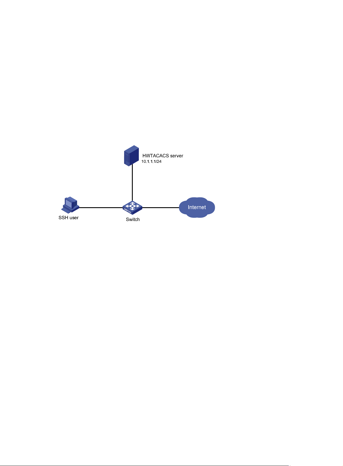
AAA configuration examples
AAA for SSH users by an HWTACACS server
Network requirements
As shown in Figure 9, configure the switch to meet the following requirements:
• Use the HWTACACS server for SSH user authentication, authorization, and accounting.
• Assign the default user role network-operator to SSH users after they pass authentication.
• Exclude domain names from the usernames sent to the HWTACACS server.
• Use expert as the shared keys for secure HWTACACS communication.
Figure 9 Network diagram
Configuration procedure
1. Configure the HWTACACS server:
# Set the shared keys for secure communication with the switch to expert. (Details not shown.)
# Add an account for the SSH user and specify the password. (Details not shown.)
2. Configure the switch:
# Assign IP addresses to the interfaces. (Details not shown.)
# Create an HWTACACS scheme.
<Switch> system-view
[Switch] hwtacacs scheme hwtac
# Specify the primary authentication server.
[Switch-hwtacacs-hwtac] primary authentication 10.1.1.1 49
# Specify the primary authorization server.
[Switch-hwtacacs-hwtac] primary authorization 10.1.1.1 49
# Specify the primary accounting server.
[Switch-hwtacacs-hwtac] primary accounting 10.1.1.1 49
# Set the shared keys for secure HWTACACS communication to expert in plain text.
[Switch-hwtacacs-hwtac] key authentication simple expert
[Switch-hwtacacs-hwtac] key authorization simple expert
[Switch-hwtacacs-hwtac] key accounting simple expert
# Exclude domain names from the usernames sent to the HWTACACS server.
[Switch-hwtacacs-hwtac] user-name-format without-domain
[Switch-hwtacacs-hwtac] quit
38
Page 47

# Create ISP domain bbb and configure the domain to use the HWTACACS scheme for
authentication, authorization, and accounting of login users.
[Switch-isp-bbb] authentication login hwtacacs-scheme hwtac
[Switch-isp-bbb] authorization login hwtacacs-scheme hwtac
[Switch-isp-bbb] accounting login hwtacacs-scheme hwtac
[Switch-isp-bbb] quit
# Create local RSA and DSA key pairs.
[Switch] public-key local create rsa
[Switch] public-key local create dsa
# Enable the SSH service.
[Switch] ssh server enable
# Enable scheme authentication for user lines VTY 0 through VTY 63.
[Switch] line vty 0 63
[Switch-line-vty0-63] authentication-mode scheme
[Switch-line-vty0-63] quit
# Enable the default user role feature to assign authenticated SSH users the default user role
network-operator.
[Switch] role default-role enable
Verifying the configuration
# Initiate an SSH connection to the switch, and enter the correct username and password. The user
logs in to the switch. (Details not shown.)
# Verify that the user can use the commands permitted by the network-operator user role. (Details
not shown.)
Local authentication, HWTACACS authorization, and RADIUS accounting for SSH users
Network requirements
As shown in Figure 10, configure the switch to meet the following requirements:
• Perform local authentication for SSH servers.
• Use the HWTACACS server and RADIUS server for SSH user authorization and accounting,
respectively.
• Exclude domain names from the usernames sent to the servers.
• Assign the default user role network-operator to SSH users after they pass authentication.
Configure an account with the username hello for the SSH user. Configure the shared keys for
secure communication with the HWTACACS server and RADIUS server to expert.
39
Page 48

Figure 10 Network diagram
Configuration procedure
1. Configure the HWTACACS server. (Details not shown.)
2. Configure the RADIUS server. (Details not shown.)
3. Configure the switch:
# Assign IP addresses to interfaces. (Details not shown.)
# Create local RSA and DSA key pairs.
<Switch> system-view
[Switch] public-key local create rsa
[Switch] public-key local create dsa
# Enable the SSH service.
[Switch] ssh server enable
# Enable scheme authentication for user lines VTY 0 through VTY 63.
[Switch] line vty 0 63
[Switch-line-vty0-63] authentication-mode scheme
[Switch-line-vty0-63] quit
# Configure an HWTACACS scheme.
[Switch] hwtacacs scheme hwtac
[Switch-hwtacacs-hwtac] primary authorization 10.1.1.2 49
[Switch-hwtacacs-hwtac] key authorization simple expert
[Switch-hwtacacs-hwtac] user-name-format without-domain
[Switch-hwtacacs-hwtac] quit
# Configure a RADIUS scheme.
[Switch] radius scheme rd
[Switch-radius-rd] primary accounting 10.1.1.1 1813
[Switch-radius-rd] key accounting simple expert
[Switch-radius-rd] user-name-format without-domain
[Switch-radius-rd] quit
# Create a device management user.
[Switch] local-user hello class manage
# Assign the SSH service for the local user.
[Switch-luser-manage-hello] service-type ssh
# Set a password for the local user to 123456TESTplat&! in plain text. In FIPS mode, you must
set the password in interactive mode.
[Switch-luser-manage-hello] password simple 123456TESTplat&!
[Switch-luser-manage-hello] quit
40
Page 49
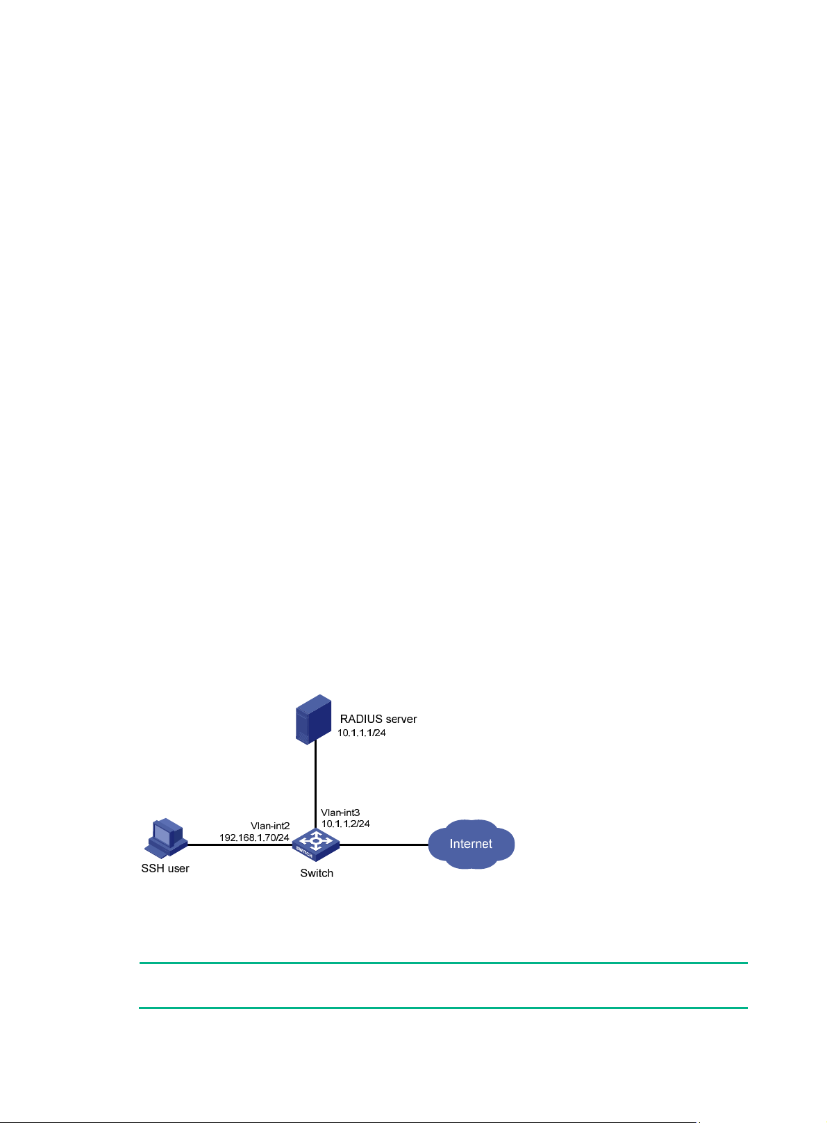
# Create ISP domain bbb and configure the login users to use local authentication,
HWTACACS authorization, and RADIUS accounting.
[Switch] domain bbb
[Switch-isp-bbb] authentication login local
[Switch-isp-bbb] authorization login hwtacacs-scheme hwtac
[Switch-isp-bbb] accounting login radius-scheme rd
[Switch-isp-bbb] quit
# Enable the default user role feature to assign authenticated SSH users the default user role
network-operator.
[Switch] role default-role enable
Verifying the configuration
# Initiate an SSH connection to the switch, and enter the username hello@bbb and the correct
password. The user logs in to the switch. (Details not shown.)
# Verify that the user can use the commands permitted by the network-operator user role. (Details
not shown.)
Authentication and authorization for SSH users by a RADIUS server
Network requirements
As shown in Figure 11, configure the switch to meet the following requirements:
• Use the RADIUS server for SSH user authentication and authorization.
• Include domain names in the usernames sent to the RADIUS server.
• Assign the default user role network-operator to SSH users after they pass authentication.
The RADIUS server runs on IMC. Add an account with the username hello@bbb on the RADIUS
server.
The RADIUS server and the switch use expert as the shared key for secure RADIUS comm unication.
The ports for authentication and accounting are 1812 and 1813, respectively.
Figure 11 Network diagram
Configuration procedure
1. Configure the RADIUS server on IMC 5.0:
NOTE:
In this example, the RADIUS server runs on IMC PLAT 5.0 (E0101) and IMC UAM 5.0 (E0101).
41
Page 50

# Add the switch to the IMC Platform as an access device.
Log in to IMC, click the Service tab, and select User Access Manager > Access Device
Management > Access Device from the navigation tree. Then, click Add to configure an
access device as follows:
a. Set the shared key for secure RADIUS communication to expert.
b. Set the ports for authentication and accounting to 1812 and 1813, respectively.
c. Select the service type Device Management Service.
d. Select the access device type HP.
e. Select the access device from the device list or manually add the access device (with the IP
address 10.1.1.2).
f. Leave the default settings for other parameters and click OK.
The IP address of the access device specified here must be the same as the source IP address
of the RADIUS packets sent from the switch. The source IP address is chosen in the following
order on the switch:
{ IP address specified by the nas-ip command.
{ IP address specified by the radius nas-ip command.
{ IP address of the outbound interface (the default).
Figure 12 Adding the switch as an access device
# Add an account for device management.
Click the User tab, and select Access User View > Device Mgmt User from the navigation
tree. Then, click Add to configure a device management account as follows:
a. Enter the account name hello@bbb and specify the password.
b. Select the service type SSH.
c. Specify 10.1.1.0 to 10.1.1.255 as the IP address range of the hosts to be managed.
d. Click OK.
NOTE:
The IP address range must contain the IP address of the switch.
42
Page 51

Figure 13 Adding an account for device management
2. Configure the switch:
# Assign an IP address to VLAN-interface 2, the SSH user access interface.
<Switch> system-view
[Switch] interface vlan-interface 2
[Switch-Vlan-interface2] ip address 192.168.1.70 255.255.255.0
[Switch-Vlan-interface2] quit
# Assign an IP address to VLAN-interface 3, through which the switch communicates with the
server.
[Switch] interface vlan-interface 3
[Switch-Vlan-interface3] ip address 10.1.1.2 255.255.255.0
[Switch-Vlan-interface3] quit
# Create local RSA and DSA key pairs.
[Switch] public-key local create rsa
[Switch] public-key local create dsa
# Enable the SSH service.
[Switch] ssh server enable
# Enable scheme authentication for user lines VTY 0 through VTY 63.
[Switch] line vty 0 63
[Switch-line-vty0-63] authentication-mode scheme
[Switch-line-vty0-63] quit
# Enable the default user role feature to assign authenticated SSH users the default user role
network-operator.
[Switch] role default-role enable
# Create a RADIUS scheme.
43
Page 52

[Switch] radius scheme rad
# Specify the primary authentication server.
[Switch-radius-rad] primary authentication 10.1.1.1 1812
# Set the shared key for secure communication with the server to expert in plain text.
[Switch-radius-rad] key authentication simple expert
# Include domain names in the usernames sent to the RADIUS server.
[Switch-radius-rad] user-name-format with-domain
[Switch-radius-rad] quit
# Create ISP domain bbb and configure authentication, authorization, and accounting methods
for login users.
[Switch] domain bbb
[Switch-isp-bbb] authentication login radius-scheme rad
[Switch-isp-bbb] authorization login radius-scheme rad
[Switch-isp-bbb] accounting login none
[Switch-isp-bbb] quit
Verifying the configuration
# Initiate an SSH connection to the switch, and enter the username hello@bbb and the correct
password. The user logs in to the switch. (Details not shown.)
# Verify that the user can use the commands permitted by the network-operator user role. (Details
not shown.)
Troubleshooting RADIUS
RADIUS authentication failure
Symptom
User authentication always fails.
Analysis
Possible reasons include:
• A communication failure exists between the NAS and the RADIUS server.
• The username is not in the userid@isp-name format, or the ISP domain is not correctly
configured on the NAS.
• The user is not configured on the RADIUS server.
• The password entered by the user is incorrect.
• The RADIUS server and the NAS are configured with diff erent shared keys.
Solution
To resolve the problem:
1. Check the following items:
{ The NAS and the RADIUS server can ping each other.
{ The username is in the userid@isp-name format and the ISP domain is correctly configure d
on the NAS.
{ The user is configured on the RADIUS server.
{ The correct password is entered.
{ The same shared key is configured on both the RADIUS server and the NAS.
44
Page 53

2. If the problem persists, contact Hewlett Packard Enterprise Support.
RADIUS packet delivery failure
Symptom
RADIUS packets cannot reach the RADIUS server.
Analysis
Possible reasons include:
• A communication failure exists between the NAS and the RADIUS server.
• The NAS is not configured with the IP address of the RADIUS server.
• The authentication and accounting UDP ports configured on the NAS are incorrect.
• The RADIUS server's authentication and accounting port numbers are being used by other
applications.
Solution
To resolve the problem:
1. Check the following items:
{ The link between the NAS and the RADIUS server work well at both the physical and data
link layers.
{ The IP address of the RADIUS server is correctly configured on the NAS.
{ The authentication and accounting UDP port numbers configure d on the NAS are the same
as those of the RADIUS server.
{ The RADIUS server's authentication and accounting port numbers are available.
2. If the problem persists, contact Hewlett Packard Enterprise Support.
RADIUS accounting error
Symptom
A user is authenticated and authorized, but accounting for the user is not normal.
Analysis
The accounting server configuration on the NAS is not correct. Possible reasons include:
• The accounting port number configured on the NAS is incorrect.
• The accounting server IP address configured on the NAS is incorrect. For example, the NAS i s
configured to use a single server to provide authentication, authorization, and accounting
services, but in fact the services are provided by different servers.
Solution
To resolve the problem:
1. Check the following items:
{ The accounting port number is correctly configured.
{ The accounting server IP address is correctly configured o n the NAS.
2. If the problem persists, contact Hewlett Packard Enterprise Support.
Troubleshooting HWTACACS
Similar to RADIUS troubleshooting. See "Troubleshooting RADIUS."
45
Page 54

Configuring password control
Overview
Password control allows you to implement the following features:
• Manage login and super password setup, expirations, and updates for device management
users.
• Control user login status based on predefined policies.
Local users are divided into two types: device management users and network access users. This
feature applies only to device management users. For more information about local users, see
"Configuring AAA."
Password setting
Minimum password length
You can define the minimum length of user passwords. If a user enters a password that is shorter
than the minimum length, the system rejects the password.
Password composition policy
A password can be a comb ination of ch aracters from the following types:
• Uppercase letters A to Z.
• Lowercase letters a to z.
• Digits 0 to 9.
• Special characters. For information about special characters, see the password-control
composition command in Security Command Reference.
Depending on the system's security requirements, you can set the minimum number of character
types a password must contain and the minimum number of characters for each type, as shown
in Table 4.
Table 4
In non-FIPS mode, all the combination levels are available for a password. In FIPS mode, only the
level 4 combination is available for a password.
Password composition policy
Password combination
level
Level 1 One One
Level 2 Two One
Level 3 Three One
Level 4 Four One
Minimum number of
character types
Minimum number of characters
for each type
When a user sets or changes a password, the system checks if the password meets the combination
requirement. If not, the operation fails.
Password complexity checking policy
A less compli cated password such as a password containing the username or rep eated characters is
more likely to be cracked. For higher security, you can configure a password complexity checking
policy to ensure that all user passwords are relatively complicated. With such a policy configured,
46
Page 55

when a user configures a password, the system checks the complexity of the password. If the
password is complexity-incompliant, the configuration will fail.
You can apply the following password complexity requirements:
• A password cannot contain the username or the reverse of the username. For example, if the
username is abc, a password such as abc982 or 2cba is not complex enough.
• A character or number cannot be included three or more times consecutively. For example,
password a111 is not complex enough.
Password updating and expiration
Password updating
This feature allows you to set the minimum interval at which users can change their passwords. If a
user logs in to change the password but the time passed since the last change is less than this
interval, the system denies the request. For example, if you set this interval to 48 hours, a user
cannot change the password twice within 48 hours.
The set minimum interval is not effective when a user is prompted to change the password at the first
login or after its password aging time expires.
Password expiration
Password expiration imposes a lifecycle on a user password. After the password expires, the user
needs to change the password.
If a user enters an expired password when logging in, the system displays an error message. The
user is prompted to provide a new password and to confirm it by entering it a gain. The new password
must be valid, and the user must enter exactly the same password when confirming it.
Telnet users, SSH users, and console users can change their own passwords. The administrator
must change passwords for FTP users.
Early notice on pending password expiration
When a user logs in, the system checks whether the password will expire in a time equal to or less
than the specified notification period. If so, the system notifies the user when the passwo rd will expire
and provides a choice for the user to change the password. If the user sets a new password that is
complexity-compliant, the system records the new password and the setup time. If the user chooses
not to change the password or the user fails to change it, the system allows the user to log in using
the current password.
Telnet users, SSH users, and console users can change their own passwords. The administrator
must change passwords for FTP users.
Login with an expired password
You can allow a user to log in a certain number of times within a period of time after the password
expires. For example, if you set the maximum number of logins with an expired password to 3 and
the time period to 15 days, a user can log in three times within 15 days after the password expires.
Password history
With this feature enabled, the system stores passwords that a user has used. When a user cha nges
the password, the system checks the new password against the current password a nd tho se stored
in the password history records. The new password must be different from the current one and those
stored in the history records by at least four characters. The four characters must be different from
one another. Otherwise, the system will display an error message, and the password will not be
changed.
You can set the maximum number of history password records for the system to maintain for each
user. When the number of history password records exceeds your setting, the most recent record
overwrites the earliest one.
47
Page 56

Current login passwords of device management users are not stored in the password history,
because a device management user password is saved in cipher text and cannot be recovered to a
plaintext password.
User login control
First login
With the global password control feature enabled, users must change the password at first login
before they can access the system. In this situation, password changes are not subject to the
minimum change interval.
Login attempt limit
Limiting the number of consecutive login failures can effectively prevent password guessing.
Login attempt limit takes effect on FTP and VTY users. It does not take effect on the following types
of users:
• Nonexistent users (users not configured on the device).
• Users logging in to the device through console ports.
If a user fails to log in, the system adds the user account and the user's IP address to the password
control blacklist. After making the maximum number of consecutive attempts, login attempt limit
limits the user and user account in any of the following ways:
• Disables the user account until the account is manually removed from the password control
blacklist.
• Allows the user to continue using the user account. The user's IP address and user account are
removed from the password control blacklist when the user uses this account to successfully
log in to the device.
• Disables the user account for a period of time.
The user can use the account to log in when either of the following conditions exists:
{ The locking timer expires.
{ The account is manually removed from the password control blacklist before the locking
timer expires.
NOTE:
This account is locked only for this user. Other users can still use this account, and the blacklisted
user can use other user accounts.
Maximum account idle time
Y ou can set the maximu m account idle time for user accounts. When an a ccount is idle for this period
of time since the last successful login, the account becomes invalid.
Password not displayed in any form
For security purposes, nothing is displayed when a user enters a password.
Logging
The system logs all successful password changing events and user adding events to the password
control blacklist.
48
Page 57

FIPS compliance
The device supports the FIPS mode that complies with NIST FIPS 140-2 requirements. Support for
features, commands, and parameters might differ in FIPS mode (see "Configuring FIPS") and
non-FIPS mode.
Password control configuration task list
The password control features can be configured in several different views, and different views
support different features. The settings configured in different views or for different objects have the
following application ranges:
• Settings for super passwords apply only to super passwords.
• Settings in local user view apply only to the password of the local user.
• Settings in user group view apply to the passwords of the local users in the user group if you do
not configure password policies for these users in local user view.
• Global settings in system view apply to the passwords of the local users in all user groups if you
do not configure password policies for these users in both local user view and user group vie w.
For local user passwords, the settings with a smaller application scope have higher priority.
To configure password control, perform the following tasks:
Tasks at a glance
(Required.) Enabling password control
(Optional.) Setting global password control parameters
(Optional.) Setting user group password control parameters
(Optional.) Setting local user password control parameters
(Optional.) Setting super password control parameters
Enabling password control
To successfully enable the global password control feature and allow device management users to
log in to the device, the device must have sufficient storage space.
Enabling the global password control feature is the prerequisite for all password control
configurations to take effect. Then, for a specific password control feature to take effect, enable this
password control feature.
After the global password control feature is enabled, you cannot display the password and super
password configurations for device management users by using the corresponding display
commands. However, the configuration for network access user passwords can be displayed. The
first password configured for device management users must contain at least four different
characters.
To enable password control:
Step Command Remarks
1. Enter system view.
2. Enable the global password
control feature.
system-view
password-control enable
49
N/A
• In non-FIPS mode, the global
password control feature is
disabled by default.
Page 58

•
Step Command Remarks
In FIPS mode, the global
password control feature is
enabled and cannot be
disabled by default.
3. (Optional.) Enable a specific
password control feature.
password-control { aging |
composition | history | length }
enable
By default, all four password
control features are enabled.
Setting global password control parameters
The password expiration time, minimum password length, and password composition policy can be
configured in system view , user grou p view, or local user view . The password settings with a smaller
application scope have higher priority. Global settings in system view apply to the passwords of the
local users in all user groups if you do not configure password policies for these users in both local
user view and user group view .
The password-control login-attempt command takes effect immediately and can affect the users
already in the password control blacklist. Other password control configurations do not take ef fect on
users that have been logged in or passwords that have been configured.
To set global password control parameters:
Step Command Remarks
1. Enter system view.
2. Set the password expiration
time.
3. Set the minimum password
update interval.
4. Set the minimum password
length.
5. Configure the password
composition policy.
system-view
password-control aging
aging-time
password-control
update-interval
password-control length
password-control composition
type-number
type-length
[
interval
type-number
type-length ]
length
N/A
The default setting is 90 days.
The default setting is 24 hours.
• In non-FIPS mode, the default
setting is 10 characters.
• In FIPS mode, the default
length is 15 characters.
• In non-FIPS mode, a default
password must contain at
least one character type and
at least one character for each
type.
• In FIPS mode, a default
password must contain at
least four character types and
at least one character for each
type.
6. Configure the password
complexity checking policy.
7. Set the maximum number of
history password records for
each user.
8. Configure the login attempt
limit.
password-control complexity
same-character | user-name
{
check
password-control history
exceed
time |
50
{
unlock
lock |
} ]
max-record-num
password-control login-attempt
login-times [
lock-time
By default, the system does not
}
perform password complexity
checking.
The default setting is 4.
By default, the maximum number
of login attempts is 3 and a user
failing to log in after the specified
number of attempts must wait for
1 minute before trying again.
Page 59

Step Command Remarks
9. Set the number of days
during which a user is
notified of the pending
password expiration.
10. Set the maximum number of
days and maximum number
of times that a user can log in
after the password expires.
11. Set the maximum account
idle time.
password-control
alert-before-expire
password-control
expired-user-login delay
times
idle-time
times
password-control login
idle-time
alert-time
delay
The default setting is 7 days.
By default, a user can log in three
times within 30 days after the
password expires.
The default setting is 90 days.
Setting user group password control parameters
Step Command Remarks
1. Enter system view.
2. Create a user group and
enter user group view.
system-view
user-group
group-name
N/A
By default, no user group exists.
For information about how to
configure a user group, see
"Configuring AAA."
3. Configure the password
expiration time for the user
group.
4. Configure the minimum
password length for the user
group.
5. Configure the password
composition policy for the
user group.
6. Configure the password
complexity checking policy
for the user group.
7. Configure the login attempt
limit.
password-control aging
aging-time
password-control length
password-control composition
type-number
type-length
[
password-control complexity
same-character | user-name
{
check
password-control login-attempt
login-times [
lock-time
type-number
type-length ]
exceed
unlock
time |
lock |
{
} ]
length
By default, the password
expiration time of the user group
equals the global password
expiration time.
By default, the minimum
password length of the user group
equals the global minimum
password length.
By default, the password
composition policy of the user
group equals the global password
composition policy.
By default, the password
complexity checking policy of the
}
user group equals the global
password complexity checking
policy.
By default, the login-attempt
policy of the user group equals the
global login-attempt policy.
Setting local user password control parameters
Step Command Remarks
1. Enter system view.
2. Create a device
management user and enter
local user view.
system-view
local-user
manage
user-name
51
class
N/A
By default, no local user exists.
Local user password control
applies to device management
users instead of network access
Page 60

Step Command Remarks
users.
For information about how to
configure a local user, see
"Configuring AAA."
By default, the setting equals that
3. Configure the password
expiration time for the local
user.
4. Configure the minimum
password length for the local
user.
5. Configure the password
composition policy for the
local user.
password-control aging
aging-time
password-control length
password-control composition
type-number
type-length
[
type-number
type-length ]
length
for the user group to which the
local user belongs. If no expiration
time is configured for the user
group, the global setting applies to
the local user.
By default, the setting equals that
for the user group to which the
local user belongs. If no minimum
password length is configured for
the user group, the global setting
applies to the local user.
By default, the settings equal
those for the user group to which
the local user belongs. If no
password composition policy is
configured for the user group, the
global settings apply to the local
user.
By default, the settings equal
6. Configure the password
complexity checking policy
for the local user.
7. Configure the login attempt
limit.
password-control complexity
same-character | user-name
{
check
password-control login-attempt
login-times [
lock-time
time |
exceed
{
unlock
lock |
} ]
those for the user group to which
the local user belongs. If no
}
password complexity checking
policy is configured for the user
group, the global settings apply to
the local user.
By default, the settings equal
those for the user group to which
the local user belongs. If no
login-attempt policy is configured
for the user group, the global
settings apply to the local user.
Setting super password control parameters
The super password allows you to obtain a temporary user role without reconnecting to the device.
For more information, see Fundamentals Configuration Guide.
To set super password control paramet ers:
Step Command Remarks
1. Enter system view.
2. Set the password expiration
time for super passwords.
3. Configure the minimum
length for super passwords.
4. Configure the password
composition policy for super
system-view
password-control super aging
aging-time
password-control super length
length
password-control super
N/A
The default setting is 90 days.
• In non-FIPS mode, the default
setting is 10 characters.
• In FIPS mode, the default
setting is 15 characters.
• In non-FIPS mode, a default
super password must contain
52
Page 61

r
f
Step Command Remarks
passwords.
composition type-numbe
type-number [
type-length ]
type-length
at least one character type
and at least one character for
each type.
• In FIPS mode, a default super
password must contain at
least four character types and
at least one character for each
type.
Displaying and maintaining password control
Execute display commands in any view and reset commands in user view.
Task Command
Display password control configuration.
display password-control [ super
]
Display information about users in the
password control blacklist.
Delete users from the password control
blacklist.
Clear history password records.
NOTE:
display password-control blacklist [ user-name
ip
ipv4-address ]
reset password-control blacklist [ user-name
reset password-control history-record [ user-name
name |
super [ role
role name ] ]
The reset password-control history-record command ca n delete the history password records o
one or all users even when the password history feature is disabled.
Password control configuration example
Network requirements
Configure a global password control policy to meet the following requirements:
• A password must contain at least 16 characters.
• A password must contain at least four character types and at least four characters for each type.
• An FTP or VTY user failing to provide the correct password in two successive login attempts is
permanently prohibited from logging in.
• A user ca n log in five times within 60 days after the password expires.
• A password expires after 30 days.
• The minimum password update interval is 36 hours.
• The maximum account idle time is 30 days.
• A password cannot contain the username or the reverse of the username.
• No character appears consecutively three or more times in a password.
name |
name ]
Configure a super password control policy for user role network-operator to meet the following
requirements:
• A super password must contain at least 24 characters.
53
Page 62

• A super password must contain at least four character types and at least five characters for
each type.
Configure a password control policy for the local Telnet user test to meet the following requirements:
• The password must contain at least 24 characters.
• The password must contain at least four character types and at least five characters for each
type.
• The password for the local user expires after 20 days.
Configuration procedure
# Enable the password control feature globally.
<Sysname> system-view
[Sysname] password-control enable
# Disable a user account permanently if a user fails two consecutive login attempts on the user
account.
[Sysname] password-control login-attempt 2 exceed lock
# Set all passwords to expire after 30 days.
[Sysname] password-control aging 30
# Globally set the minimum password length to 16 characters.
[Sysname] password-control length 16
# Set the minimum password update interval to 36 hours.
[Sysname] password-control update-interval 36
# Specify that a user can log in five times within 60 days after the password expires.
[Sysname] password-control expired-user-login delay 60 times 5
# Set the maximum account idle time to 30 days.
[Sysname] password-control login idle-time 30
# Refuse any password that contains the username or the reverse of the username.
[Sysname] password-control complexity user-name check
# Specify that no character can be included three or more times consecutively in a password.
[Sysname] password-control complexity same-character check
# Globally specify that all passwords must each contain at least four character types and at least four
characters for each type.
[Sysname] password-control composition type-number 4 type-length 4
# Set the minimum super password length to 24 characters.
[Sysname] password-control super length 24
# Specify that a super password must contain at least four character types and at least five
characters for each type.
[Sysname] password-control super composition type-number 4 type-length 5
# Configure a super password used for switching to user role network-operator as
123456789ABGFTweuix@#$%! in plain text.
[Sysname] super password role network-operator simple 123456789ABGFTweuix@#$%!
Updating user information. Please wait ... ...
# Create a device management user named test.
[Sysname] local-user test class manage
# Set the service type of the user to Telnet.
54
Page 63

[Sysname-luser-manage-test] service-type telnet
# Set the minimum password length to 24 for the local user.
[Sysname-luser-manage-test] password-control length 24
# Specify that the password of the local user must contain at least four character types and at least
five characters for each type.
[Sysname-luser-manage-test] password-control composition type-number 4 type-length 5
# Set the password for the local user to expire after 20 days.
[Sysname-luser-manage-test] password-control aging 20
# Configure the password of the local user in interactive mode.
[Sysname-luser-manage-test] password
Password:
Confirm :
Updating user information. Please wait ... ...
[Sysname-luser-manage-test] quit
Verifying the configuration
# Display the global password control configuration.
<Sysname> display password-control
Global password control configurations:
Password control: Enabled
Password aging: Enabled (30 days)
Password length: Enabled (16 characters)
Password composition: Enabled (4 types, 4 characters per type)
Password history: Enabled (max history record:4)
Early notice on password expiration: 7 days
Maximum login attempts: 2
Action for exceeding login attempts: Lock
Minimum interval between two updates: 36 hours
User account idle time: 30 days
Logins with aged password: 5 times in 60 days
Password complexity: Enabled (username checking)
Enabled (repeated characters checking)
# Display the password control configuration for super passwords.
<Sysname> display password-control super
Super password control configurations:
Password aging: Enabled (90 days)
Password length: Enabled (24 characters)
Password composition: Enabled (4 types, 5 characters per type)
# Display the password control configuration for local user test.
<Sysname> display local-user user-name test class manage
Total 1 local users matched.
Device management user test:
State: Active
Service type: Telnet
User group: system
55
Page 64

Bind attributes:
Authorization attributes:
Work directory: flash:
User role list: network-operator
Password control configurations:
Password aging: Enabled (20 days)
Password length: Enabled (24 characters)
Password composition: Enabled (4 types, 5 characters per type)
56
Page 65

Managing public keys
Overview
This chapter describes public key management for the following asymmetric key algorithms:
• Revest-Shamir-Adleman Algorithm (RSA).
• Digital Signature Algo rithm (DSA).
• Elliptic Curve Digital Signature Algorithm (ECDSA).
Many security applications, including SSH, use asymmetric key algorithms to secure
communications between two parties, as shown in Figure 14.
separate keys (one public and one private) for encryption and decryption. Symmetric key algorithms
use only one key.
Figure 14 Encryption and decryption
Asymmetric key algorithms use two
Sender
Plain text Cipher text Plain text
A key owner can distri bute the public key in plain text on the network but must keep the private key in
privacy. It is mathematically infeasible to calculate the private key even if an attacker knows the
algorithm and the public key.
The security applications use the asymmetric key algorithms for the followi ng purposes:
• Encryption and decryption—Any public key receiver can use the public key to encrypt
information, but only the private key owner can decrypt the information.
• Digital signature—The ke y owner uses the private key to "sign" information to be sent, and the
receiver decrypts the information with the sender's public key to verify information authenticity.
RSA, DSA, and ECDSA can all perform digital signature, but only RSA can perform encryption and
decryption.
Asymmetric key algorithms enables secure key distribution on an insecure n etwork, but the security
strength of an asymmetric key algorithm still depends on key size as with any symmetric key
algorithm.
Key
Encryption Decryption
FIPS compliance
Key
Receiver
The device supports the FIPS mode that complies with NIST FIPS 140-2 requirements. Support for
features, commands, and parameters might differ in FIPS mode (see "Configuring FIPS") and
non-FIPS mode.
Creating a local key pair
Configuration guidelines
When you create a local key pair, follow these guidelines:
• The key algorithm must be the same as required by the security application.
57
Page 66

• The key modulus length must be appropriate (see Table 5). The longer the key modulus length,
the higher the security, the longer the key generation time.
• If you do not assign the key pair a name, the system assigns the default name to the key pair
and marks the key pair as default. Y ou can also assign the default name to another key pair , but
the system does not mark the key pair as default.
• The name of a key pair must be unique among all manually named key pairs that use the same
key algorithm, but can be the same as a key pair that uses a different key algorit hm. If a name
conflict occurs, the system asks whether you want to overwrite the existing key pair.
• The key pairs are automatically saved and can survive system reboots.
Table 5 A comparison of different types of asymmetric key algorithms
Type Generated key pairs Modulus length
• In non-FIPS mode:
{ One host key pair, if you specify a key pair
RSA
name.
{ One server key pair and one h ost ke y pair,
if you do not specify a key pair name.
Both key pairs use their default names.
• In FIPS mode: One host key pair.
NOTE:
Only SSH 1.5 uses the RSA server key pair.
• In non-FIPS mode: 512 to 2048 bits,
1024 bits by default.
To ensure security, use a minimum of
768 bits.
• In FIPS mode: 2048 bits.
• In non-FIPS mode: 512 to 2048 bits,
1024 bits by default.
DSA One host key pair.
ECDSA One host key pair. 192 bits.
To ensure security, use a minimum of
768 bits.
• In FIPS mode: 2048 bits.
Configuration procedure
To create a local key pair:
Step Command Remarks
1. Enter system view.
2. Create local DSA or RSA key
pairs.
system-view
public-key local create { dsa
ecdsa | rsa
} [
name
key-name ]
|
Distributing a local host public key
Y ou must dist ribute a local host public key to a peer d evice so the peer device can use th e public key
to encrypt information sent to the local device or authenticate the digital signature signed by the local
device.
N/A
By default, no local key pair exists.
To distribute a local host public key:
1. Record the key or export the key to a file
2. Transfer the key, for example, by using FTP or TFTP
58
Page 67

This section covers only the first task.
The following are the methods available for recording or exporting a local host pu blic key:
• Exporting a host public key in a specific format to a file. Use this method if you can import public
keys from a file on the peer device.
• Displaying a host public key in a specific format and saving it to a file. Use this method if you can
import public keys from a file on the peer device.
• Displaying a host public key. Use this method if you must manually enter the key on the peer
device.
Exporting a host public key in a specific format to a file
Step Command
1. Enter system view.
2. Export a local host public key
in a specific format to a file.
system-view
• Export an RSA host public key:
{ In non-FIPS mode:
public-key local export rsa [ name key-name ] { openssh |
ssh1 | ssh2 } filename
{ In FIPS mode:
public-key local export rsa [ name key-name ] { openssh |
ssh2 } filename
• Export a DSA host public key:
public-key local export dsa [ name key-name ] { openssh |
ssh2 } filename
Displaying a host public key in a specific format and saving it to a file
After you display a host public key in a specific format, save the key to a file and transfer the file to the
peer device.
To display a local host public key in a specific format:
Step Command
1. Enter system view.
2. Display local host public keys
in a specific format.
system-view
• Display RSA host public keys:
{ In non-FIPS mode:
public-key local export rsa [ name key-name ] { openssh |
ssh1 | ssh2 }
{ In FIPS mode:
public-key local export rsa [ name key-name ] { openssh |
ssh2 }
• Display DSA host public keys:
public-key local export dsa [ name key-name ] { openssh |
ssh2 }
Displaying a host public key
Display a host public key and copy it to an unformatted file. You must literally enter the key on the
peer device.
Perform the following tasks in any view:
59
Page 68

Task Command
Display local RSA public keys.
display public-key local rsa public
name
[
key-name ]
Display local DSA public keys.
NOTE:
display public-key local dsa public
Do not distribute the RSA server public key serverkey (default) to a peer device.
Destroying a local key pair
To avoid key compromise, destroy the local key pair and generate a new pair after any of the
following conditions occurs:
• An intrusion event has occurred.
• The storage media of the device is replaced.
• The local certificate has expired.
To destroy a local key pair:
Step Command Remarks
1. Enter system view.
2. Destroy a local key pair.
system-view
public-key local destroy
ecdsa | rsa
} [
name
dsa
{
key-name ]
name
[
N/A
|
N/A
key-name ]
Configuring a peer public key
To encrypt information sent to a peer device or authenticate the digital signature of the peer device,
you must configure the public key of the peer device on the local device.
Table 6 Peer public key configuration methods
Method Prerequisites Remarks
3. Save the host public key in a file
Import the peer public key
from a public key file
(recommended)
Manually enter (type or copy)
the peer public key
For information about displaying or exporting host public keys, see "Distributing a local host public
key."
on the peer device.
4. Get the file from the peer
device, for example, by using
FTP or TFTP in binary mode.
Display and record the public key on
the peer device.
IMPORTANT:
If the peer device is an HPE device,
use the display public-key local
public command to display the
public key. The format of the public
key displayed in any other way might
be incorrect.
The system automatically converts
the imported public key to a string in
the Public Key Cryptography
Standards (PKCS) format.
• If the key is not in the correct
format, the system discards the
key and displays an error
message. If the key is valid, for
example, the key displayed by
the display public-key local
public command, the system
saves the key.
• Always use the first method if
you are not sure of the format of
the recorded public key.
60
Page 69

Importing a peer host public key from a public key file
Step Command Remarks
1. Enter system view.
2. Import a peer host public key
from a public key file.
system-view
public-key peer
sshkey
filename
keyname
import
N/A
By default, no peer host
public key exists.
Entering a peer public key
Step Command Remarks
1. Enter system view.
2. Specify a name for the peer
public key and enter public
key view.
system-view
public-key peer
keyname
N/A
By default, no peer host public key
exists.
3. Type or copy the key.
4. Return to system view.
N/A
peer-public-key end
You can use spaces and carriage
returns, but the system does not save
them.
When you exit public key view, the
system automatically saves the public
key.
Displaying and maintaining public keys
Execute display commands in any view .
Task Command
Display local public keys.
Display peer public keys.
display public-key local { dsa
key-name ]
display public-key peer
key-name ]
[
ecdsa | rsa } public
|
brief
name
|
publickey-name ] [
Examples of public key management
name
[
name
Example for entering a peer public key
Network requirements
As shown in Figure 15, to prevent illegal access, Device B authenticates Device A through a digital
signature. Before configuring authentication parameters on Device B, configure the public key of
Device A on Device B.
• Configure Device B to use the asymmetric key algorithm of RSA to authenticate Device A.
• Manually specify the host public key of Device A on Device B.
61
Page 70

Figure 15 Network diagram
Device A Device B
Configuration procedure
1. Configure Device A:
# Create local RSA key pairs with default names on Device A, and use the default modulus
length 1024 bits.
<DeviceA> system-view
[DeviceA] public-key local create rsa
The range of public key modulus is (512 ~ 2048).
If the key modulus is greater than 512, it will take a few minutes.
Press CTRL+C to abort.
Input the modulus length [default = 1024]:
Generating Keys...
.................++++++
......................................++++++
.....++++++++
..............++++++++
Create the key pair successfully.
# Display all local RSA public keys.
[DeviceA] display public-key local rsa public
=============================================
Key name: hostkey (default)
Key type: RSA
Time when key pair created: 16:48:31 2011/05/12
Key code:
30819F300D06092A864886F70D010101050003818D0030818902818100DA3B90F59237347B
8D41B58F8143512880139EC9111BFD31EB84B6B7C7A1470027AC8F04A827B30C2CAF79242E
45FDFF51A9C7E917DB818D54CB7AEF538AB261557524A7441D288EC54A5D31EFAE4F681257
6D7796490AF87A8C78F4A7E31F0793D8BA06FB95D54EBB9F94EB1F2D561BF66EA27DFD4788
CB47440AF6BB25ACA50203010001
=============================================
Key name: serverkey (default)
Key type: RSA
Time when key pair created: 16:48:31 2011/05/12
Key code:
307C300D06092A864886F70D0101010500036B003068026100C9451A80F7F0A9BA1A90C7BC
1C02522D194A2B19F19A75D9EF02219068BD7FD90FCC2AF3634EEB9FA060478DD0A1A49ACE
E1362A4371549ECD85BA04DEE4D6BB8BE53B6AED7F1401EE88733CA3C4CED391BAE633028A
AC41C80A15953FB22AA30203010001
2. Configure Device B:
# Enter the host public key of Device A in public key view. The key must be literally the same as
displayed on Device A.
<DeviceB> system-view
[DeviceB] public-key peer devicea
Enter public key view. Return to system view with "peer-public-key end" command.
62
Page 71

[DeviceB-pkey-public-key-devicea]30819F300D06092A864886F70D010101050003818D003081
890
2818100DA3B90F59237347B
[DeviceB-pkey-public-key-devicea]8D41B58F8143512880139EC9111BFD31EB84B6B7C7A14700
27A
C8F04A827B30C2CAF79242E
[DeviceB-pkey-public-key-devicea]45FDFF51A9C7E917DB818D54CB7AEF538AB261557524A744
1D2
88EC54A5D31EFAE4F681257
[DeviceB-pkey-public-key-devicea]6D7796490AF87A8C78F4A7E31F0793D8BA06FB95D54EBB9F
94E
B1F2D561BF66EA27DFD4788
[DeviceB-pkey-public-key-devicea]CB47440AF6BB25ACA50203010001
# Save the public key and return to system view.
[DeviceB-pkey-public-key-devicea] peer-public-key end
Verifying the configuration
# Verify that the key is the same as on Device A.
[DeviceB] display public-key peer name devicea
=============================================
Key name: devicea
Key type: RSA
Key modulus: 1024
Key code:
30819F300D06092A864886F70D010101050003818D0030818902818100DA3B90F59237347B
8D41B58F8143512880139EC9111BFD31EB84B6B7C7A1470027AC8F04A827B30C2CAF79242E
45FDFF51A9C7E917DB818D54CB7AEF538AB261557524A7441D288EC54A5D31EFAE4F681257
6D7796490AF87A8C78F4A7E31F0793D8BA06FB95D54EBB9F94EB1F2D561BF66EA27DFD4788
CB47440AF6BB25ACA50203010001
Example for importing a public key from a public key file
Network requirements
As shown in Figure 16, Device B authenticates Device A through a digital signature. Before
configuring authentication parameters on Device B, configure the public key of Device A on Device
B.
• Configure Device B to use the asymmetric key algorithm of RSA to authenticate Device A.
• Import the host public key of Device A from the public key file to Device B.
Figure 16 Network diagram
Configuration procedure
1. Configure Device A:
# Create local RSA key pairs with default names on Device A, and use the default modulus
length 1024 bits.
63
Page 72

<DeviceA> system-view
[DeviceA] public-key local create rsa
The range of public key modulus is (512 ~ 2048).
If the key modulus is greater than 512, it will take a few minutes.
Press CTRL+C to abort.
Input the modulus length [default = 1024]:
Generating Keys...
.................++++++
......................................++++++
.....++++++++
..............++++++++
Create the key pair successfully.
# Display all local RSA public keys.
[DeviceA] display public-key local rsa public
=============================================
Key name: hostkey (default)
Key type: RSA
Time when key pair created: 16:48:31 2011/05/12
Key code:
30819F300D06092A864886F70D010101050003818D0030818902818100DA3B90F59237347B
8D41B58F8143512880139EC9111BFD31EB84B6B7C7A1470027AC8F04A827B30C2CAF79242E
45FDFF51A9C7E917DB818D54CB7AEF538AB261557524A7441D288EC54A5D31EFAE4F681257
6D7796490AF87A8C78F4A7E31F0793D8BA06FB95D54EBB9F94EB1F2D561BF66EA27DFD4788
CB47440AF6BB25ACA50203010001
=============================================
Key name: serverkey (default)
Key type: RSA
Time when key pair created: 16:48:31 2011/05/12
Key code:
307C300D06092A864886F70D0101010500036B003068026100C9451A80F7F0A9BA1A90C7BC
1C02522D194A2B19F19A75D9EF02219068BD7FD90FCC2AF3634EEB9FA060478DD0A1A49ACE
E1362A4371549ECD85BA04DEE4D6BB8BE53B6AED7F1401EE88733CA3C4CED391BAE633028A
AC41C80A15953FB22AA30203010001
# Export the RSA host public key to the file devicea.pub.
[DeviceA] public-key local export rsa ssh2 devicea.pub
[DeviceA] quit
# Enable the FTP server function, create an FTP user with the username ftp and password 123,
and configure the FTP user role as network-admin.
[DeviceA] ftp server enable
[DeviceA] local-user ftp
[DeviceA-luser-manage-ftp] password simple 123
[DeviceA-luser-manage-ftp] service-type ftp
[DeviceA-luser-manage-ftp] authorization-attribute user-role network-admin
[DeviceA-luser-manage-ftp] quit
2. Configure Device B:
# Use FTP in binary mode to get the public key file devicea.pub from Device A.
<DeviceB> ftp 10.1.1.1
Connected to 10.1.1.1 (10.1.1.1).
64
Page 73

220 FTP service ready.
User(10.1.1.1:(none)):ftp
331 Password required for ftp.
Password:
230 User logged in.
Remote system type is UNIX.
Using binary mode to transfer files.
ftp> binary
200 TYPE is now 8-bit binary
ftp> get devicea.pub
227 Entering Passive Mode (10,1,1,1,118,252)
150 Accepted data connection
226 File successfully transferred
301 bytes received in 0.003 seconds (98.0 kbyte/s)
ftp> quit
221-Goodbye. You uploaded 0 and downloaded 1 kbytes.
221 Logout.
# Import the host public key from the key file devicea.pub.
<DeviceB> system-view
[DeviceB] public-key peer devicea import sshkey devicea.pub
Verifying the configuration
# Verify that the host public key is the same as it is on Device A.
[DeviceB] display public-key peer name devicea
=============================================
Key name: devicea
Key type: RSA
Key modulus: 1024
Key code:
30819F300D06092A864886F70D010101050003818D0030818902818100DA3B90F59237347B
8D41B58F8143512880139EC9111BFD31EB84B6B7C7A1470027AC8F04A827B30C2CAF79242E
45FDFF51A9C7E917DB818D54CB7AEF538AB261557524A7441D288EC54A5D31EFAE4F681257
6D7796490AF87A8C78F4A7E31F0793D8BA06FB95D54EBB9F94EB1F2D561BF66EA27DFD4788
CB47440AF6BB25ACA50203010001
65
Page 74

Configuring PKI
Overview
Public Key Infrastructure (PKI) is an asymmetric key infrastructure to encrypt and decrypt data for
securing network services. Data encrypted with the public key can b e decrypted only with the private
key. Likewise, data encrypted with the private key can be decrypted only with the public key.
PKI uses digital certificates to distribute and employ public keys, and provides network
communication and e-commerce with security services such as user authentication, data
confidentiality, and data integrity.
HPE's PKI system provides certificate management for IPsec and SSL.
PKI terminology
Digital certificate
A digital certificate is a n electronic d ocument signed by a CA that binds a public key with the identity
of its owner.
A digital certificate includes the following information:
• Issuer name (the name of the CA that issued the certificate).
• Subject name (name of the individual or group to which the certificate is issued).
• Identity information of the subject.
• Subject's public key.
• Signature of the CA.
• Period of validity.
A digital certificate must comply with the international standard s of ITU-T X.509, of which X.509 v3 is
the most commonly used.
This chapter covers the following types of certificates:
• CA certificate—Certificate of a CA. Multiple CAs in a PKI system form a CA tree, with the root
CA at the top. The root CA gene rate s a self-sig ned certificate, and e ach lo wer level CA hol ds a
CA certificate issued by the CA immediately above it. The chain of these certificates forms a
chain of trust.
• Registration authority (RA) certificate—Certificate issued by a CA to an RA. RAs act as
proxies for CAs to process enrollment requests in a PKI system.
• Local certificate—Digital certificate issued by a CA to a PKI entity, which contains the entity's
public key.
• Peer certificate—Digital certificate of a peer , which contains the peer's public key and is sign ed
by a CA.
Certificate revocation list
A certificate revocation list (CRL ) is a list of serial numbers for certificates that have been revo ked. A
CRL is created and signed by the CA that originally issued the certificates.
The CA publishes CRLs periodically to revoke certificates. Entities that are associated with the
revoked certificates should not be trusted.
The CA must revoke a certificate when any of the following conditions occurs:
• The certificate subject name is changed.
66
Page 75

• The private key is compromised.
• The association between the subject and CA is changed. For example, when an employee
terminates employment with an organization.
CA policy
A CA policy is a set of criteria that a CA follows to process certificate requests, to issue and revoke
certificates, and to publish CRLs. Typically, a CA advertises its policy in a certification practice
statement (CPS). You can obtain a CA policy through out-of-band means such as phone, disk, and
email. Make sure you understand the CA policy before you select a truste d CA for certificate request
because different CAs might use different policies.
PKI architecture
A PKI system consists of PKI entities, C As, RAs and a ce rtificate/CRL repository, as shown in Figure
17.
Figure 17 PKI architecture
• PKI entity—An end user using PKI certificates. The PKI entity can be an op erator, an
organization, a device like a router or a switch, or a process running on a computer. PKI entities
use SCEP to communicate with the CA or RA.
• CA—Certification authority that grants and manages certificates. A CA issues certificates,
defines the certificate validity periods, and revokes certificates by publishing CRLs.
• RA—Registration authority, which offloads the CA by processing enrollment requests. The RA
accepts certificate requests, verifies user identity, and determines whether to ask the CA to
issue certificates.
The RA is optional in a PKI system. In cases when the CA operates over a wide geographical
area or when there is security concern over exposing the CA to direct network access, it is
advisable to delegate some of the tasks to an RA and leave the CA t o concentrate on its primary
tasks of signing certificates and CRLs.
• Certificate/CRL repository—A certificate distribution point that stores certificates and CRLs,
and distributes these certificates and CRLs to PKI entities. It also provides the query function. A
PKI repository can be a directory server using the LDAP or HTTP protocol, of which L DAP is
commonly used.
PKI operation
The following workflow describes how a PKI entity requests a local certificate from a CA that has
RAs:
67
Page 76
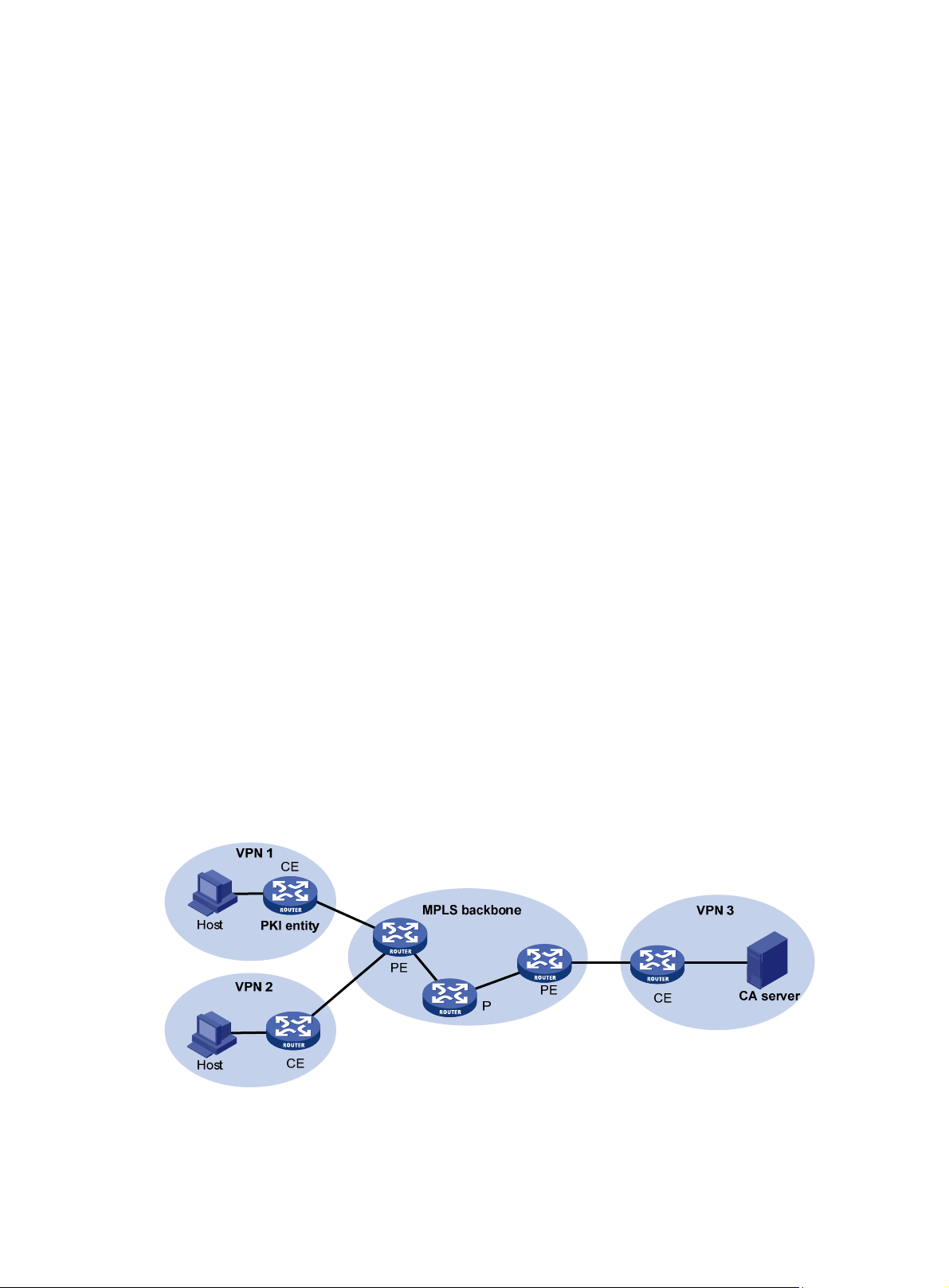
1. A PKI entity submits a certificate request to the RA.
2. The RA verifies the identity of the entity and sends a digital signature containing the identity
information and the public key to the CA.
3. The CA verifies the digital signature, approves the request, and issues a certificate.
4. After receiving the certificate from the CA, the RA sends the certificate to the certificate
repositories and notifies the PKI entity that the certificate has been issued.
5. The entity obtains the certificate from the certificate repository.
PKI applications
The PKI technology can meet security requirements of online transactions. As an infrast ructure, PKI
has a wide range of applications. Here are some application examples.
• VPN—A VPN is a private data communi cation network built on the public communication
infrastructure. A VPN can use net work layer security protocols (for example, IPsec) in
conjunction with PKI-based encryption and digital signature technologies for confidentiality.
• Secure emails—PKI can address the email requirements for confidentiality, integrity,
authentication, and non-repudiation. A common secure email protocol is Secure/Multipurpose
Internet Mail Extensions (S/MIME), which is based on PKI and allows for transfer of encrypted
mails with signature.
Support for MPLS L3VPN
An enterprise might have multiple branches in different VPNs. PKI support for MPLS L3VPN is
required if users in different VPNs request certificates from the CA server in the headquarters VPN.
As shown in Figure 18, the PKI entity in
the following workflow:
1. The PKI entity submits a certificate request to the CA server.
2. The PE device that connects to the PKI entity transmits the request to the CA server through
MPLS L3VPN.
3. The CA server verifies the request and issues the certificate.
4. The PE device that connects to the CA server transmits the certificate to the PKI entity.
For information about MPLS L3VPN, see MPLS Configuration Guide.
Figure 18 PKI support for MPLS L3VPN
VPN 1 requests a certificate from the CA server in VPN 3 in
68
Page 77

Feature and software version compatibility
The PKI feature is available in Release 2137 and later versions.
FIPS compliance
The device supports the FIPS mode that complies with NIST FIPS 140-2 requirements. Support for
features, commands, and parameters might differ in FIPS mode (see "Configuring FIPS") and
non-FIPS mode.
PKI configuration task list
Tasks at a glance
(Required.) Configuring a PKI entity
(Required.) Configuring a PKI domain
(Required.) Requesting a certificate:
• Configuring automatic certificate request
• Manually requesting a certificate
(Optional.) Aborting a certificate request
(Optional.) Obtaining certificates
(Optional.) Verifying PKI certificates
(Optional.) Specifying the storage path for the certificates and CRLs
(Optional.) Exporting certificates
(Optional.) Removing a certificate
(Optional.) Configuring a certificate-based access control policy
Configuring a PKI entity
A certificate applicant uses an entity to provide its identity information to a CA. A valid PKI entity must
include one or more of following identity categories:
• Distinguished name (DN) of the entity, which further includes the common name, county code,
locality, organization, unit in the organization, and state. If you configure the DN for an entity, a
common name is required.
• FQDN of the entity.
• IP address of the entity.
Whether the categories are required or optional depends on the CA policy. Follow the CA policy to
configure the entity settings. For example, if the CA policy requires the entity DN, but you configure
only the IP address, the CA rejects the certificate request from the entity.
The SCEP add-on on the Windows 200 0 CA server h as restrictions on the data length of a ce rtificate
request. If a request from a PKI entity exceeds the data length limit, the CA server does not respond
to the certificate request. In this case, you can use an out-of-band means to submit the request.
Other types of CA server s, such as RSA server s and OpenCA servers, do not have such rest rictions.
To configure a PKI entity:
69
Page 78

Step Command Remarks
1. Enter system view.
system-view
N/A
2. Create a PKI entity and
enter its view.
3. Set a common name for the
entity .
4. Set the country code of the
entity .
5. Set the locality of the entity.
6. Set the organization of the
entity .
7. Set the unit of the entity in
the organization.
8. Set the state where the
entity resides.
9. Set the FQDN of the entity.
10. Configure the IP address of
the entity.
pki entity
common-name
common-name-sting
country
locality
organization
organization-unit
org-unit-name
state
fqdn
ip
{ ip-address |
interface-type
interface-number }
entity-name
country-code-string
locality-name
org-name By default, the organization is not set.
state-name B y default, the state is not set.
fqdn-name-string
Configuring a PKI domain
interface
By default, no PKI entities exist.
To create multiple PKI entities, repeat
this step.
By default, the common name is not
set.
By default, the country code is not set.
By default, the locality is not set.
By default, the unit is not set.
By default, the FQDN is not set.
By default, the IP address is not
configured.
A PKI domain contains enrollment information for a PKI entity. It is locally significant and is intended
only for reference by other applications like IKE and SSL.
To configure a PKI domain:
Step Command Remarks
1. Enter system view.
2. Create a PKI domain
and enter its view.
3. Specify the trusted
CA.
4. Specify the PKI entity
name.
5. Specify the type of
certificate request
reception authority.
6. Specify the certificate
request URL.
system-view
pki domain
ca identifier
certificate request entity
certificate request from
certificate request url
vpn-instance
[
domain-name By default, no PKI domains exist.
name
url-string
vpn-instance-name ]
N/A
By default, no trusted CA is
specified.
To obtain a CA certificate, the
trusted CA name must be
provided.
The trusted CA name uniquely
identifies the CA to be used if
multiple CAs exist on the same
CA server. The CA server's URL
is specified by using the
certificate request url
entity-name By default, no entity is specified.
{ ca | ra }
By default, no authority type is
specified.
By default, the certificate request
URL is not specified.
command.
70
Page 79

Step Command Remarks
Do not configure this command
when you request a certificate in
offline mode.
7. (Optional.) Set the
SCEP polling interval
and maximum
number of polling
attempts.
8. (Optional.) Specify the
LDAP server.
9. Enter a fingerprint to
be matched against
the fingerprint of the
root CA certificate.
certificate request polling
interval
count |
ldap-server host
port-number ] [
vpn-instance-name ]
• In non-FIPS mode:
root-certificate fingerprint { md5 |
sha1 } string
• In FIPS mode:
root-certificate fingerprint sha1
string
minutes }
hostname [
vpn-instance
count
{
port
By default, the switch polls the CA
server for the certificate request
status every 20 minutes. The
maximum number of polling
attempts is 50.
This task is required only when
the CRL repository is an LDAP
server and the URL of the CRL
repository does not contain the
host name of the LDAP server.
By default, no LDAP server is
specified.
Before a PKI entity can enroll with
a CA, it must authenticate the CA
by obtaining the self-signed
certificate of the CA and verifying
the fingerprint of the CA
certificate.
If a fingerprint is not entered in the
PKI domain, and if the CA
certificate is imported or obtained
through manual certificate
request, you must verify the
fingerprint that is displayed during
authentication of the CA
certificate.
If the CA certificate is obtained
through automatic certificate
request, the certificate will be
rejected if a fingerprint has not
been entered.
By default, no fingerprint is
specified.
10. Specify the key pair
for certificate request.
11. (Optional.) Specify the
intended use for the
certificate.
• Specify an RSA key pair:
public-key rsa { { encryption name
encryption-key-name [ length
key-length ] | signature name
signature-key-name [ length
key-length ] } * | general name
key-name [ length key-length ] }
• Specify a DSA key pair:
public-key dsa name key-name
[ length key-length ]
usage { ike | ssl-client
71
ssl-server
|
By default, no key pair is
specified.
If the specified key pair does not
exist, the PKI entity automatically
creates the key pair before
submitting a certificate request.
For information about creating key
pairs, see "Managing public keys."
By default, the certificate can be
used by all applications, including
IKE, SSL clients, and SSL server.
} *
The extension options contained
in an issued certificate depend on
Page 80

Step Command Remarks
12. (Optional.) Specify a
source IP address for
the PKI protocol
packets.
source ip {
{interface-type interface-number }
ip-address |
Requesting a certificate
To request a certificate, a PKI entity must provide its identity information and public key to a CA.
A certificate request can be submitted to a CA in offline or online mode.
• Offline mode—A certificate request is submitted by using an out-of-band method, such as
phone, disk, or email. You can use this mode a s required o r if you fail to request a certificate i n
online mode.
To submit a certificate request in offline mode:
a. Use pki request-certificate domain pkcs10 to print the request information on the
terminal or use pki request-certificate domain pkcs10 filename to save the request
information to a local file.
b. Send the printed information or the saved file to the CA by using an out-of-band method to
submit the request.
• Online mode—A certificate request can be automatically or manually submitted. This section
describes the online request mode.
interface
the CA policy, and they might be
different from those specified in
the PKI domain.
This task is required if the CA
policy requires that the CA server
accept certificate requests from a
specific IP address or subnet.
By default, the source IP address
of PKI protocol packets is the IP
address of their outgoing
interface.
Configuration guidelines
The following guidelines apply to certificate request for an entity in a PKI domain:
• Make sure the device is time synchronized with the CA server . Otherwise, the certificate requ est
might fail because the certificate is considered to be outside of the validity period. For
information about how to configure the system time, see Fundamentals Configuration Guide.
• To request a new certificate for a PKI entity that already has a local certificate, perform the
following steps:
a. Use the pki delete-certificate command to delete the existing local certificate.
b. Use the public-key local create to generate a new key pair. The new key pair will
automatically overwrite the old key pair in the domain.
c. Submit a new certificate request.
• After a new certificate is obtained, do not use the public-key local create or public-key local
destroy command to generate or destroy a key pair with the same name a s the key pai r in th e
local certificate. Otherwise, the existing local certificate becomes unavailable.
• A PKI domain can have local ce rtificates using only one type of cryptographic algorithms (DSA
or RSA). If DSA is used, a PKI domain can have only one local certificate. If RSA is used, a PKI
domain can have one local certificate for signature, and one local certificate for encryption.
72
Page 81

Configuring automatic certificate request
IMPORTANT:
The device does not support automatic certificate rollover. To avoid service interruptions, you must
manually submit a certificate renewal request before the current certificate expires.
In auto request mode, a PKI entity automatically submits a certificate request to the CA when an
application works with the PKI entity that does not have a local certificate. For example, when IKE
negotiation uses a digital signature for identity authentication, but no local certificate is available, the
entity automatically submits a certificate request. It saves the certificate locally after obtaining it from
the CA.
A CA certificat e must be present before you request a local ce rtificate. If no CA certificate exists in the
PKI domain, the PKI entity automatically obtains a CA certificate bef ore sending a certificate request.
To configure automatic certificate request:
Step Command Remarks
1. Enter system view.
2. Enter PKI domain view.
3. Set the certificate request
mode to auto.
system-view
pki domain
certificate request mode auto
password { cipher
[
password ]
domain-name N/A
simple
|
}
N/A
By default, the manual
request mode applies.
In auto request mode, set
a password for certificate
revocation as required by
the CA policy.
Manually requesting a certificate
Before you manually submit a certificate request, make sure the CA certificate exists and a key pair
is specified for the PKI domain:
• The CA certifi cate is u se d to verify the authenticity and validity of the obtained lo cal certificate.
• The key pair is used for certificate request. Upon receiving the public key and the identity
information, the CA signs and issues a certificate.
After the CA issues the certificate, the device obtains and saves it locally.
To manually request a certificate:
Step Command Remarks
1. Enter system view.
2. Enter PKI domain view.
3. Set the certificate
request mode to
manual.
4. Return to system view.
5. Obtain the CA
certificate.
6. Submit a certificate
request or generate a
certificate request in
PKCS#10 format.
system-view
pki domain
certificate request mode manual
quit
See "Obtaining certificates." N/A
pki request-certificate domain
domain-name [
pkcs10
[
domain-name N/A
password
filename
[
password ]
filename ] ]
N/A
By default, the manual request
mode applies.
N/A
This command is not saved in
the configuration file.
This command triggers the PKI
entity to automatically generate
73
Page 82

Step Command Remarks
Aborting a certificate request
Before the CA issues a certificate, you can abort a certificate request and change its parameters,
such as the common name, country code, or FQDN. You can use the display pki certificate
request-status command to display the status of a certificate request.
Alternatively, you also can remove a PKI domain to abort the associated certificate request.
To abort a certificate request:
Step Command Remarks
1. Enter system view.
system-view
a key pair if the key pair
specified in the PKI domain
does not exist. The name,
algorithm, and length of the key
pair are configured in the PKI
domain.
N/A
2. Abort a certificate request.
pki abort-certificate-request
domain
Obtaining certificates
Y ou can obtain the CA certificate, local ce rtificates, and peer certificates related to a PKI domain from
a CA and save them locally for higher lookup efficiency. To do so, use either the offline mode or the
online mode:
• In offline mode, obtain the certificates by an out-of-band means like FTP, disk, or email, and
then import them locally . Use this mode when the CRL repo sitory is not specified, the CA server
does not support SCEP, or the CA server generates the key pair for the certificates.
• In online mode, you can obtain the CA certificate thro ugh SCEP and obtain local certificates or
peer certificates through LDAP.
Configuration prerequisites
To obtain local or peer certificates in online mode, specify the LDAP server for the PKI domain.
To import local or peer certificates in offline mode, perform the following tasks:
• Use FTP or TFTP to upload the certificate files to the storage media of the device. If FTP or
TFTP is not available, display and copy the contents of a certificate t o a file on the device. Make
sure the certificate is in PEM format because only certificates in PEM format can be imported.
• T o import a ce rtificate, a CA certificate chain must exist in the PKI domain, or be contained in th e
certificate. If the CA certificate chain is not available, obtain it before importing the certifi cate.
domain-name
This command is not saved in the
configuration file.
Configuration guidelines
• To import a local certificate containing an encrypted key pair, you must provide the challenge
password. Contact the CA administrator to obtain the password.
74
Page 83

• If a CA certificate already exists locally, you cannot obtain it again in online mode. If you want to
obtain a new one, use the pki delete-certificate command to remove the existing CA certificate
and local certificates first.
• If local or peer certificates already exist, you can obtain new local or peer certificates to
overwrite the existing ones. If RSA is used, a PKI domain can have two local certificates, one for
signature and the other for encryption.
• If CRL checking is enabled, obtaining a certificate triggers CRL checki ng. If the certificate to b e
obtained has been revoked, the certificate cannot be obtained.
• The device compares the validity period of a certificate with the local system time to determine
whether the certificate is valid. Make sure the system time of the device is synchronized with the
CA server.
Configuration procedure
To obtain certificates:
Step Command Remarks
1. Enter system view.
2. Obtain certificates.
system-view
• Import certificates in offline mode:
pki import domain domain-name { der
{ ca | local | peer } filename filename | p12
local filename filename | pem { ca | local |
peer } [ filename filename ] }
• Obtain certificates in online mode:
pki retrieve-certificate domain
domain-name { ca | local | peer
entity-name }
N/A
pki
The
retrieve-certificate
command is not saved
in the configuration
file.
Verifying PKI certificates
A certificate is automatically verified when it is requested, obtained, or used by an application. If the
certificate expires, if it is not issued by a trusted CA, or if it is revoked, the certificate cannot be used.
You can also manually verify a certificate. If it has been revoked, the certificate cannot be requested
or obtained.
Verifying certificates with CRL checking
CRL checking checks whet her a certificate is in the CRL. If it is, the certificate has been revoked an d
its home entity is not trusted.
To use CRL checking, a CRL must be obtained from a CRL repository. The device selects a CRL
repository in the following order:
1. CRL repository specified in the PKI domain by using this command.
2. CRL repository in the certificate that is being verified.
3. CRL repository in the CA certificate or CRL repository in the upper-level CA certificate if the CA
certificate is the certificate being verified.
If no CRL repository is found after the selection process, the device obtains the CRL through SCEP.
In this scenario, the CA certificate and the local certificates must have been obtained.
To verify certificates with CRL checking:
75
Page 84

Step Command Remarks
1. Enter system view.
2. Enter PKI domain view.
3. (Optional.) Specify the URL
of the CRL repository.
system-view
pki domain
crl url
vpn-instance-name ]
domain-name N/A
url-string [
vpn-instance
N/A
By default, the URL of the CRL
repository is not specified.
4. Enable CRL checking.
5. Return to system view.
6. Obtain the CA certificate.
7. (Optional.) Obtain the CRL
and save it locally.
8. Verify the validity of the
certificates.
crl check enable
quit
See "Obtaining certificates."
pki retrieve-crl domain
domain-name
pki validate-certificate domain
domain-name { ca |
local
}
By default, CRL checking is
enabled.
N/A
N/A
The newly obtained CRL overwrites
the old one, if any.
The obtained CRL must be issued
by a CA certificate in the CA
certificate chain in the current
domain.
N/A
Verifying certificates without CRL checking
Step Command Remarks
1. Enter system view.
2. Enter PKI domain view.
system-view
pki domain
domain-name N/A
N/A
3. Disable CRL checking.
4. Return to system view.
5. Obtain the CA certificate.
6. Verify the validity of the
certificates.
undo crl check enable
quit
See "Obtaining certificates."
pki validate-certificate domain
ca
domain-name {
local
|
}
By default, CRL checking is
enabled.
N/A
N/A
This command is not saved in the
configuration file.
Specifying the storage path for the certificates and CRLs
CAUTION:
If you change the storage path, save the configuration before you reboot or shut down the device to
avoid loss of the certificates or the CRLs.
The device has a default storage path for certificates and CRLs. You can change the storage path
and specify different paths for the certificates and CRLs.
76
Page 85

After you change the storage path for certificates or CRLs, the certificate files (with the .cer or .p12
extension) and CRL files (with the .crl extension) in the original path are moved to the new path.
To specify the storage path for the certificates and CRLs:
Task Command Remarks
Specify the storage path for
certificates and CRLs.
pki storage { certificates |
crls }
dir-path
Exporting certificates
IMPORTANT:
To export all certificates in the PKCS12 format, the PKI domain must have a minimum of one local
certificate. Otherwise, the certificates in the PKI domain cannot be exported.
You can export the CA certificate and the local certificates in a PKI domain to certificate files. The
exported certificate files can then be imported back to the device or other PKI applications.
When you export a local certificate with the RSA key pair, the name of the target file might not be the
same as specified in the command. It depends on the purpose of the key pair of the certificate.
By default, the device stores certificates and
CRLs in the PKI directory on the storage
media of the device.
To export certificates:
Step Command Remarks
1. Enter system
view.
2. Export certificates.
system-view
• Export certificates in DER format:
pki export domain domain-name der { all |
ca | local } filename filename
• Export certificates in PKCS12 format:
pki export domain domain-name p12 { all |
local } passphrase p12passwordstring
filename filename
• Export certificates in PEM format:
pki export domain domain-name pem
{ { all | local } [ { 3des-cbc | aes-128-cbc |
aes-192-cbc | aes-256-cbc | des-cbc }
pempasswordstring ] | ca } [ filename
filename ]
Removing a certificate
You can remove the CA certificate, local certificate, or peer certificates in a PKI domain. After you
remove the CA certificate, the system automatically removes the local certificates, peer certificates,
and CRLs in the domain.
N/A
If you do not specify a file
name when you export a
certificate in PEM format, the
certificate is displayed on the
terminal.
Y ou can rem ove a local certificate and reque st a new one when the local ce rtificate is about to expire
or the certificate's private key is compromised. To remove a local certificate and request a new
certificate, perform the following tasks:
1. Remove the local certificate.
2. Use the public-key local destroy command to destroy the existing local key pair.
3. Use the public-key local create command to generate a new key pair.
4. Request a new certificate.
77
Page 86

To remove a certificate:
Step Command Remarks
1. Enter system view.
2. Remove a certificate.
system-view
pki delete-certificate domain
local
peer
|
|
[
serial
serial-num ] }
domain-name {
N/A
If you use the
keyword without
ca
specifying a serial
number, the command
removes all peer
certificates.
peer
Configuring a certificate-based access control policy
Certificate-based access control policies allow you to authorize access to a device (for example, an
HTTPS server) based on the attributes of an authenticated client's certificate.
A certificate-base d access control policy is a set of access control rules (permit or deny statem ents),
each associated with a certificate attribute group. A certificate attribute group contains multiple
attribute rules, each defining a matching criterion for an attribute in the certificate issuer name,
subject name, or alternative subject name field.
If a certificate matches all attribute rules in a certificate attribute group associated with an access
control rule, the system determines that the certificate matches the access control rule. In this
scenario, the match process stops, and the system performs the access control action defined in the
access control rule.
The following conditions describe how a certificate-based access control policy verifies the validity of
a certificate:
• If a certificate matches a permit statement, the certificate passes the verification.
• If a certificate matches a deny statement or does not match any statements in the policy, the
certificate is regarded invalid.
• If a statement is associated with a non-existing attribute group, or the attribute group does not
have attribute rules, the certificate matches the statement.
• If the certificate-based access control policy referenced by a security application (for example,
HTTPS) does not exist, all certificates in the application pass the verification.
To configure a certificate-based access control policy:
Step Command Remarks
1. Enter system view.
2. Create a certificate attribute
group and enter its view.
3. (Optional.) Configure an
attribute rule for issuer name,
subject name, or alternative
subject name.
4. Return to system view.
5. Create a certificate-based
access control policy and
enter its view.
system-view
pki certificate attribute-group
group-name
attribute
fqdn
{
subject-name
ctn
{
|
attribute-value
quit
pki certificate
access-control-policy
policy-name
alt-subject-name
id {
equ
|
issuer-name
} { dn |
nctn
| ip } | {
nequ
|
fqdn
}
|
| ip } }
N/A
By default, no certificate attribute
groups exist.
By default, not attribute rules are
configured.
N/A
By default, no certificate-based
access control policy exists.
78
Page 87

Step Command Remarks
6. Create a certificate access
control rule.
rule [
id ] {
group-name
deny | permit
}
Displaying and maintaining PKI
Execute display commands in any view .
Task Command
Display the contents of a certificate.
display pki certificate domain
serial
[
serial-num ] }
By default, no certificate access
control rules are configured, and
all certificates can pass the
verification.
You can create multiple access
control rules are for a
certificate-based access control
policy.
domain-name {
ca | local | peer
Display certificate request status.
Display locally stored CRLs in a PKI
domain.
Display certificate attribute group
information.
Display certificate-based access control
policy information.
display pki certificate request-status [ domain
display pki crl domain
display pki certificate attribute-group
display pki certificate access-control-policy
domain-name
[ group-name ]
[ policy-name ]
domain-name ]
PKI configuration examples
You can use different software applications, such as Windows server, RSA Keon, and OpenCA, to
act as the CA server.
If you use Windows server or OpenCA, you must install the SCEP add-on for Windows server or
enable SCEP for OpenCA. In either case, when you configure a PKI domain, you must use the
certificate request from ra command to specify the RA to accept certificate requests.
If you use RSA Keon, the SCEP add-o n is not required. When you configure a PKI domain, you must
use the certificate request from ca command to specify the CA to accept certificate requests.
Requesting a certificate from an RSA Keon CA server
Network requirements
Configure the PKI entity (the device) to request a local certificate from the CA server.
Figure 19 Network diagram
79
Page 88

Configuring the RSA Keon CA server
1. Create a CA server named myca:
In this example, you must configure these basic attributes on the CA server:
{ Nickname—Name of the trusted CA.
{ Subject DN—DN attributes of the CA, including the common name (CN), organization unit
(OU), organization (O), and country (C).
You can use the default values for other attributes.
2. Configure extended attributes:
Configure parameters in the Jurisdiction Configuration section on the management page of
the CA server:
{ Select the correct extension profiles.
{ Enable the SCEP autovetting function to enable the CA server to automatically approve
certificate requests without manual intervention.
{ Specify the IP address list for SCEP autovetting.
Configuring the device
1. Synchronize the system time of the device with the CA server for the device to correctly request
certificates or obtain CRLs. (Details not shown.)
2. Create an entity named aaa and set the common name to Device.
<Device> system-view
[Device] pki entity aaa
[Device-pki-entity-aaa] common-name Device
[Device-pki-entity-aaa] quit
3. Configure a PKI domain:
# Create a PKI domain named torsa and enter its view.
[Device] pki domain torsa
# Specify the name of the trusted CA as myca.
[Device-pki-domain-torsa] ca identifier myca
# Configure the URL of the CA server. The URL format is http://host:port/Issuing Jurisdiction ID,
where Issuing Jurisdiction ID is a hexadecimal string generated on the CA server.
[Device-pki-domain-torsa] certificate request url
http://1.1.2.22:446/80f6214aa8865301d07929ae481c7ceed99f95bd
# Specify the CA for accepting certificate requests.
[Device-pki-domain-torsa] certificate request from ca
# Specify the PKI entity name as aaa.
[Device-pki-domain-torsa] certificate request entity aaa
# Specify the URL of the CRL repository.
[Device-pki-domain-torsa] crl url ldap://1.1.2.22:389/CN=myca
# Specify the RSA key pair with the purpose general, the name abc, and the length 1024 bits.
[Device-pki-domain-torsa] public-key rsa general name abc length 1024
[Device-pki-domain-torsa] quit
4. Generate a local RSA key pair.
[Device] public-key local create rsa name abc
The range of public key size is (512 ~ 2048).
If the key modulus is greater than 512,it will take a few minutes.
Press CTRL+C to abort.
Input the modulus length [default = 1024]:
Generating Keys...
80
Page 89

..........................++++++
.....................................++++++
Create the key pair successfully.
5. Request a local certificate:
# Obtain the CA certificate and save it locally.
[Device] pki retrieve-certificate domain torsa ca
The trusted CA's finger print is:
MD5 fingerprint:EDE9 0394 A273 B61A F1B3 0072 A0B1 F9AB
SHA1 fingerprint: 77F9 A077 2FB8 088C 550B A33C 2410 D354 23B2 73A8
Is the finger print correct?(Y/N):y
Retrieved the certificates successfully.
# Submit a certificate request manually. You must specify a password for certificate revocation
when an RSA Keon CA server is used.
[Device] pki request-certificate domain torsa password 1111
Start to request the general certificate ...
……
Certificate requested successfully.
Verifying the configuration
# Display information about the local certificate in PKI domain torsa.
[Device] display pki certificate domain torsa local
Certificate:
Data:
Version: 3 (0x2)
Serial Number:
15:79:75:ec:d2:33:af:5e:46:35:83:bc:bd:6e:e3:b8
Signature Algorithm: sha1WithRSAEncryption
Issuer: CN=myca
Validity
Not Before: Jan 6 03:10:58 2013 GMT
Not After : Jan 6 03:10:58 2014 GMT
Subject: CN=Device
Subject Public Key Info:
Public Key Algorithm: rsaEncryption
Public-Key: (1024 bit)
Modulus:
00:ab:45:64:a8:6c:10:70:3b:b9:46:34:8d:eb:1a:
a1:b3:64:b2:37:27:37:9d:15:bd:1a:69:1d:22:0f:
3a:5a:64:0c:8f:93:e5:f0:70:67:dc:cd:c1:6f:7a:
0c:b1:57:48:55:81:35:d7:36:d5:3c:37:1f:ce:16:
7e:f8:18:30:f6:6b:00:d6:50:48:23:5c:8c:05:30:
6f:35:04:37:1a:95:56:96:21:95:85:53:6f:f2:5a:
dc:f8:ec:42:4a:6d:5c:c8:43:08:bb:f1:f7:46:d5:
f1:9c:22:be:f3:1b:37:73:44:f5:2d:2c:5e:8f:40:
3e:36:36:0d:c8:33:90:f3:9b
Exponent: 65537 (0x10001)
X509v3 extensions:
X509v3 CRL Distribution Points:
81
Page 90

Full Name:
DirName: CN = myca
Signature Algorithm: sha1WithRSAEncryption
b0:9d:d9:ac:a0:9b:83:99:bf:9d:0a:ca:12:99:58:60:d8:aa:
73:54:61:4b:a2:4c:09:bb:9f:f9:70:c7:f8:81:82:f5:6c:af:
25:64:a5:99:d1:f6:ec:4f:22:e8:6a:96:58:6c:c9:47:46:8c:
f1:ba:89:b8:af:fa:63:c6:c9:77:10:45:0d:8f:a6:7f:b9:e8:
25:90:4a:8e:c6:cc:b8:1a:f8:e0:bc:17:e0:6a:11:ae:e7:36:
87:c4:b0:49:83:1c:79:ce:e2:a3:4b:15:40:dd:fe:e0:35:52:
ed:6d:83:31:2c:c2:de:7c:e0:a7:92:61:bc:03:ab:40:bd:69:
1b:f5
To display detailed information about the CA certificate, use the display pki certificate domain
command.
Requesting a certificate from a Windows Server 2003 CA server
Network requirements
Configure the PKI entity (the device) to request a local certificate from a Windows Server 2003 CA
server.
Figure 20 Network diagram
Configuring the Windows Server 2003 CA server
1. Install the certificate service component:
a. Select Control Panel > Add or Remove Programs from the start menu.
b. Select Add/Remove Windows Components > Certificate Services.
c. Click Next to begin the installation.
d. Set the CA name. In this example, set the CA name to myca.
2. Install the SCEP add-on:
By default, Windows Server 2003 does not support SCEP. You must install the SCEP add-on
on the server for a PKI entity to register and obtain a certificate from the server. After the SCEP
add-on installation is complete, you will see a URL. Specify this URL as the certificate request
URL on the device.
3. Modify the certificate service attributes:
a. Select Control Panel > Administrative Tools > Certificate Authority from the start menu.
If the certificate service component and SCEP add-on have been installed successfully,
there should be two certificates issued by the CA to the RA.
b. Right-click the CA server in the navigation tree and select Properties > Policy Module.
c. Click Properties and then select Follow the settings in the certificate template, if
applicable. Otherwise, automatically issue the certificate.
4. Modify the Internet information services attributes:
82
Page 91

a. Select Control Panel > Administrative Tools > Internet Information Services (IIS)
Manager from the start menu.
b. Select Web Sites from the navigation tree.
c. Right-click Default Web Site and select Properties > Home Directory .
d. Specify the path for certificate service in the Local path box.
e. Specify a unique port number for the default website to avoid conflict with existing services.
In this example, port 8080 is used.
Configuring the device
1. Synchronize the device's system time with the CA server for the device to correctly request
certificates. (Details not shown.)
2. Create an entity named aaa and set the common name to test.
<Device> system-view
[Device] pki entity aaa
[Device-pki-entity-aaa] common-name test
[Device-pki-entity-aaa] quit
3. Configure a PKI domain:
# Create a PKI domain named winserver and enter its view.
[Device] pki domain winserver
# Set the name of the trusted CA to myca.
[Device-pki-domain-winserver] ca identifier myca
# Configure the certificate request URL. The URL format is
http://host:port/certsrv/mscep/mscep.dll, where host:port is the host IP address and port
number of the CA server.
[Device-pki-domain-winserver] certificate request url
http://4.4.4.1:8080/certsrv/mscep/mscep.dll
# Specify the RA to accept certificate requests.
[Device-pki-domain-winserver] certificate request from ra
# Specify the PKI entity name as aaa.
[Device-pki-domain-winserver] certificate request entity aaa
# Specify the RSA key pair with the purpose general, the name abc, and the length 1024 bits.
[Device-pki-domain-winserver] public-key rsa general name abc length 1024
[Device-pki-domain-winserver] quit
4. Generate an RSA local key pair:
[Device] public-key local create rsa name abc
The range of public key size is (512 ~ 2048).
If the key modulus is greater than 512,it will take a few minutes.
Press CTRL+C to abort.
Input the modulus length [default = 1024]:
Generating Keys...
..........................++++++
.....................................++++++
Create the key pair successfully.
5. Request a local certificate:
# Obtain the CA certificate and save it locally.
[Device] pki retrieve-certificate domain winserver ca
The trusted CA's finger print is:
MD5 fingerprint:766C D2C8 9E46 845B 4DCE 439C 1C1F 83AB
83
Page 92

SHA1 fingerprint:97E5 DDED AB39 3141 75FB DB5C E7F8 D7D7 7C9B 97B4
Is the finger print correct?(Y/N):y
Retrieved the certificates successfully.
# Submit a certificate request manually.
[Device] pki request-certificate domain winserver
Start to request the general certificate ...
……
Certificate requested successfully.
Verifying the configuration
# Display information about the local certificate in PKI domain winserver.
[Device] display pki certificate domain winserver local
Certificate:
Data:
Version: 3 (0x2)
Serial Number:
(Negative)01:03:99:ff:ff:ff:ff:fd:11
Signature Algorithm: sha1WithRSAEncryption
Issuer: CN=sec
Validity
Not Before: Dec 24 07:09:42 2012 GMT
Not After : Dec 24 07:19:42 2013 GMT
Subject: CN=test
Subject Public Key Info:
Public Key Algorithm: rsaEncryption
Public-Key: (2048 bit)
Modulus:
00:c3:b5:23:a0:2d:46:0b:68:2f:71:d2:14:e1:5a:
55:6e:c5:5e:26:86:c1:5a:d6:24:68:02:bf:29:ac:
dc:31:41:3f:5d:5b:36:9e:53:dc:3a:bc:0d:11:fb:
d6:7d:4f:94:3c:c1:90:4a:50:ce:db:54:e0:b3:27:
a9:6a:8e:97:fb:20:c7:44:70:8f:f0:b9:ca:5b:94:
f0:56:a5:2b:87:ac:80:c5:cc:04:07:65:02:39:fc:
db:61:f7:07:c6:65:4c:e4:5c:57:30:35:b4:2e:ed:
9c:ca:0b:c1:5e:8d:2e:91:89:2f:11:e3:1e:12:8a:
f8:dd:f8:a7:2a:94:58:d9:c7:f8:1a:78:bd:f5:42:
51:3b:31:5d:ac:3e:c3:af:fa:33:2c:fc:c2:ed:b9:
ee:60:83:b3:d3:e5:8e:e5:02:cf:b0:c8:f0:3a:a4:
b7:ac:a0:2c:4d:47:5f:39:4b:2c:87:f2:ee:ea:d0:
c3:d0:8e:2c:80:83:6f:39:86:92:98:1f:d2:56:3b:
d7:94:d2:22:f4:df:e3:f8:d1:b8:92:27:9c:50:57:
f3:a1:18:8b:1c:41:ba:db:69:07:52:c1:9a:3d:b1:
2d:78:ab:e3:97:47:e2:70:14:30:88:af:f8:8e:cb:
68:f9:6f:07:6e:34:b6:38:6a:a2:a8:29:47:91:0e:
25:39
Exponent: 65537 (0x10001)
X509v3 extensions:
X509v3 Key Usage:
Digital Signature, Non Repudiation, Key Encipherment, Data Encip
84
Page 93

herment
X509v3 Subject Key Identifier:
C9:BB:D5:8B:02:1D:20:5B:40:94:15:EC:9C:16:E8:9D:6D:FD:9F:34
X509v3 Authority Key Identifier:
keyid:32:F1:40:BA:9E:F1:09:81:BD:A8:49:66:FF:F8:AB:99:4A:30:21:9
B
X509v3 CRL Distribution Points:
Full Name:
URI:file://\\g07904c\CertEnroll\sec.crl
Authority Information Access:
CA Issuers - URI:http://gc/CertEnroll/gc_sec.crt
CA Issuers - URI:file://\\gc\CertEnroll\gc_sec.crt
1.3.6.1.4.1.311.20.2:
.0.I.P.S.E.C.I.n.t.e.r.m.e.d.i.a.t.e.O.f.f.l.i.n.e
Signature Algorithm: sha1WithRSAEncryption
76:f0:6c:2c:4d:bc:22:59:a7:39:88:0b:5c:50:2e:7a:5c:9d:
6c:28:3c:c0:32:07:5a:9c:4c:b6:31:32:62:a9:45:51:d5:f5:
36:8f:47:3d:47:ae:74:6c:54:92:f2:54:9f:1a:80:8a:3f:b2:
14:47:fa:dc:1e:4d:03:d5:d3:f5:9d:ad:9b:8d:03:7f:be:1e:
29:28:87:f7:ad:88:1c:8f:98:41:9a:db:59:ba:0a:eb:33:ec:
cf:aa:9b:fc:0f:69:3a:70:f2:fa:73:ab:c1:3e:4d:12:fb:99:
31:51:ab:c2:84:c0:2f:e5:f6:a7:c3:20:3c:9a:b0:ce:5a:bc:
0f:d9:34:56:bc:1e:6f:ee:11:3f:7c:b2:52:f9:45:77:52:fb:
46:8a:ca:b7:9d:02:0d:4e:c3:19:8f:81:46:4e:03:1f:58:03:
bf:53:c6:c4:85:95:fb:32:70:e6:1b:f3:e4:10:ed:7f:93:27:
90:6b:30:e7:81:36:bb:e2:ec:f2:dd:2b:bb:b9:03:1c:54:0a:
00:3f:14:88:de:b8:92:63:1e:f5:b3:c2:cf:0a:d5:f4:80:47:
6f:fa:7e:2d:e3:a7:38:46:f6:9e:c7:57:9d:7f:82:c7:46:06:
7d:7c:39:c4:94:41:bd:9e:5c:97:86:c8:48:de:35:1e:80:14:
02:09:ad:08
To display detailed information about the CA certificate, use the display pki certificate domain
command.
Requesting a certificate from an OpenCA server
Network requirements
Configure the PKI entity (the device) to request a local certificate from the CA server.
Figure 21 Network diagram
85
Page 94

Configuring the OpenCA server
The configuration is not shown. For information about how to configure an OpenCA server, see
related manuals.
When you configure the CA server, use the OpenCA version later than version 0.9.2 because the
earlier versions do not support SCEP.
Configuring the device
1. Synchronize the device's system time with the CA server for the device to correctly request
certificates. (Details not shown.)
2. Create an entity named aaa with the common name as rnd, the country code as CN, the
organization name as test, and the unit name as software.
<Device> system-view
[Device] pki entity aaa
[Device-pki-entity-aaa] common-name rnd
[Device-pki-entity-aaa] country CN
[Device-pki-entity-aaa] organization test
[Device-pki-entity-aaa] organization-unit software
[Device-pki-entity-aaa] quit
3. Configure a PKI domain:
# Create a PKI domain named openca and enter its view.
[Device] pki domain openca
# Specify the name of the trusted CA as myca.
[Device-pki-domain-openca] ca identifier myca
# Configure the certificate request URL. The URL is in the format http://host/cgi-bin/pki/scep,
where host is the host IP address of the OpenCA server.
[Device-pki-domain-openca] certificate request url
http://192.168.222.218/cgi-bin/pki/scep
# Configure the device to send certificate requests to ra.
[Device-pki-domain-openca] certificate request from ra
# Specify the PKI entity name as aaa.
[Device-pki-domain-openca] certificate request entity aaa
# Specify the RSA key pair with the purpose general, the name abc, and the length 1024 bits.
[Device-pki-domain-openca] public-key rsa general name abc length 1024
[Device-pki-domain-openca] quit
4. Generate a local RSA key pair.
[Device] public-key local create rsa name abc
The range of public key size is (512 ~ 2048).
If the key modulus is greater than 512,it will take a few minutes.
Press CTRL+C to abort.
Input the modulus length [default = 1024]:
Generating Keys...
..........................++++++
.....................................++++++
Create the key pair successfully.
5. Request a local certificate:
# Obtain the CA certificate and save it locally.
[Device] pki retrieve-certificate domain openca ca
The trusted CA's finger print is:
86
Page 95

MD5 fingerprint:5AA3 DEFD 7B23 2A25 16A3 14F4 C81C C0FA
SHA1 fingerprint:9668 4E63 D742 4B09 90E0 4C78 E213 F15F DC8E 9122
Is the finger print correct?(Y/N):y
Retrieved the certificates successfully.
# Submit a certificate request manually.
[Device] pki request-certificate domain openca
Start to request the general certificate ...
……
Certificate requested successfully.
Verifying the configuration
# Display information about the local certificate in PKI domain openca.
[Device] display pki certificate domain openca local
Certificate:
Data:
Version: 3 (0x2)
Serial Number:
21:1d:b8:d2:e4:a9:21:28:e4:de
Signature Algorithm: sha256WithRSAEncryption
Issuer: C=CN, L=shangdi ST=pukras, O=OpenCA Labs, OU=mysubUnit, CN=sub-ca,
DC=pki-subdomain, DC=mydomain-sub, DC=com
Validity
Not Before: Jun 30 09:09:09 2011 GMT
Not After : May 1 09:09:09 2012 GMT
Subject: CN=rnd, O=test, OU=software, C=CN
Subject Public Key Info:
Public Key Algorithm: rsaEncryption
Public-Key: (1024 bit)
Modulus:
00:b8:7a:9a:b8:59:eb:fc:70:3e:bf:19:54:0c:7e:
c3:90:a5:d3:fd:ee:ff:c6:28:c6:32:fb:04:6e:9c:
d6:5a:4f:aa:bb:50:c4:10:5c:eb:97:1d:a7:9e:7d:
53:d5:31:ff:99:ab:b6:41:f7:6d:71:61:58:97:84:
37:98:c7:7c:79:02:ac:a6:85:f3:21:4d:3c:8e:63:
8d:f8:71:7d:28:a1:15:23:99:ed:f9:a1:c3:be:74:
0d:f7:64:cf:0a:dd:39:49:d7:3f:25:35:18:f4:1c:
59:46:2b:ec:0d:21:1d:00:05:8a:bf:ee:ac:61:03:
6c:1f:35:b5:b4:cd:86:9f:45
Exponent: 65537 (0x10001)
X509v3 extensions:
X509v3 Basic Constraints:
CA:FALSE
Netscape Cert Type:
SSL Client, S/MIME
X509v3 Key Usage:
Digital Signature, Non Repudiation, Key Encipherment
X509v3 Extended Key Usage:
TLS Web Client Authentication, E-mail Protection, Microsoft
Smartcardlogin
87
Page 96

Netscape Comment:
User Certificate of OpenCA Labs
X509v3 Subject Key Identifier:
24:71:C9:B8:AD:E1:FE:54:9A:EA:E9:14:1B:CD:D9:45:F4:B2:7A:1B
X509v3 Authority Key Identifier:
keyid:85:EB:D5:F7:C9:97:2F:4B:7A:6D:DD:1B:4D:DD:00:EE:53:CF:FD:5B
X509v3 Issuer Alternative Name:
DNS:root@docm.com, DNS:, IP Address:192.168.154.145, IP
Address:192.168.154.138
Authority Information Access:
CA Issuers - URI:http://192.168.222.218/pki/pub/cacert/cacert.crt
OCSP - URI:http://192.168.222.218:2560/
1.3.6.1.5.5.7.48.12 - URI:http://192.168.222.218:830/
X509v3 CRL Distribution Points:
Full Name:
URI:http://192.168.222.218/pki/pub/crl/cacrl.crl
Signature Algorithm: sha256WithRSAEncryption
5c:4c:ba:d0:a1:35:79:e6:e5:98:69:91:f6:66:2a:4f:7f:8b:
0e:80:de:79:45:b9:d9:12:5e:13:28:17:36:42:d5:ae:fc:4e:
ba:b9:61:f1:0a:76:42:e7:a6:34:43:3e:2d:02:5e:c7:32:f7:
6b:64:bb:2d:f5:10:6c:68:4d:e7:69:f7:47:25:f5:dc:97:af:
ae:33:40:44:f3:ab:e4:5a:a0:06:8f:af:22:a9:05:74:43:b6:
e4:96:a5:d4:52:32:c2:a8:53:37:58:c7:2f:75:cf:3e:8e:ed:
46:c9:5a:24:b1:f5:51:1d:0f:5a:07:e6:15:7a:02:31:05:8c:
03:72:52:7c:ff:28:37:1e:7e:14:97:80:0b:4e:b9:51:2d:50:
98:f2:e4:5a:60:be:25:06:f6:ea:7c:aa:df:7b:8d:59:79:57:
8f:d4:3e:4f:51:c1:34:e6:c1:1e:71:b5:0d:85:86:a5:ed:63:
1e:08:7f:d2:50:ac:a0:a3:9e:88:48:10:0b:4a:7d:ed:c1:03:
9f:87:97:a3:5e:7d:75:1d:ac:7b:6f:bb:43:4d:12:17:9a:76:
b0:bf:2f:6a:cc:4b:cd:3d:a1:dd:e0:dc:5a:f3:7c:fb:c3:29:
b0:12:49:5c:12:4c:51:6e:62:43:8b:73:b9:26:2a:f9:3d:a4:
81:99:31:89
To display detailed information about the CA certificate, use the display pki certificate domain
command.
Certificate import and export configuration example
Network requirements
As shown in Figure 22, Device B will replace Device A in the network. The PKI domain
exportdomain on Device A has two local certificates containing the private key and one CA
certificate. To make sure the certificates are still valid after Device B replaces Device A, copy the
certificates on Device A to Device B and follow these guidelines:
• Encrypt the private key in the local certificates using 3DES_CBC with the password 111111
when you export the local certificates from Device A.
• Save the certificates on Device A in PEM format to the PKI domain importdomain on Device B.
88
Page 97

Figure 22 Network diagram
Configuration procedure
1. Export the certificate on Device A to specified files:
# Export the CA certificate to a .pem file.
<DeviceA> system-view
[DeviceA] pki export domain exportdomain pem ca filename pkicachain.pem
# Export the local certificate to a file named pkilocal.pem in PEM format, and use 3DES_CBC
to encrypt the private key with the password 111111.
[DeviceA] pki export domain exportdomain pem local 3des-cbc 111111 filename
pkilocal.pem
After the previous operations, the system generates three certificate files in PEM format: a CA
certificate file and two local certificate files. The CA certificate file is named pkicachain.pem.
The two local certificate files are named pkilocal.pem-signature and
pkilocal.pem-encryption, and contain the private key for signature and encryption,
respectively.
# Display the local certificate file pkilocal.pem-signature.
[DeviceA] quit
<DeviceA> more pkicachain.pem-sign
Bag Attributes
friendlyName:
localKeyID: 90 C6 DC 1D 20 49 4F 24 70 F5 17 17 20 2B 9E AC 20 F3 99 89
subject=/C=CN/O=OpenCA Labs/OU=Users/CN=subsign 11
issuer=/C=CN/L=shangdi/ST=pukras/O=OpenCA Labs/OU=docm/CN=subca1
-----BEGIN CERTIFICATE----MIIEgjCCA2qgAwIBAgILAJgsebpejZc5UwAwDQYJKoZIhvcNAQELBQAwZjELMAkG
…
-----END CERTIFICATE----Bag Attributes
friendlyName:
localKeyID: 90 C6 DC 1D 20 49 4F 24 70 F5 17 17 20 2B 9E AC 20 F3 99 89
Key Attributes: <No Attributes>
-----BEGIN ENCRYPTED PRIVATE KEY----MIICxjBABgkqhkiG9w0BBQ0wMzAbBgkqhkiG9w0BBQwwDgQIZtjSjfslJCoCAggA
…
-----END ENCRYPTED PRIVATE KEY-----
# Display the local certificate file pkilocal.pem-encryption.
<DeviceA> more pkicachain.pem-encr
Bag Attributes
89
Page 98

friendlyName:
localKeyID: D5 DF 29 28 C8 B9 D9 49 6C B5 44 4B C2 BC 66 75 FE D6 6C C8
subject=/C=CN/O=OpenCA Labs/OU=Users/CN=subencr 11
issuer=/C=CN/L=shangdi/ST=pukras/O=OpenCA Labs/OU=docm/CN=subca1
-----BEGIN CERTIFICATE----MIIEUDCCAzigAwIBAgIKCHxnAVyzWhIPLzANBgkqhkiG9w0BAQsFADBmMQswCQYD
…
-----END CERTIFICATE----Bag Attributes
friendlyName:
localKeyID: D5 DF 29 28 C8 B9 D9 49 6C B5 44 4B C2 BC 66 75 FE D6 6C C8
Key Attributes: <No Attributes>
-----BEGIN ENCRYPTED PRIVATE KEY----MIICxjBABgkqhkiG9w0BBQ0wMzAbBgkqhkiG9w0BBQwwDgQI7H0mb4O7/GACAggA
…
-----END ENCRYPTED PRIVATE KEY-----
2. Download the certificate files pkicachain.pem, pkilocal.pem-sign, and pkilocal.pem-encr
from Device A to the host through FTP. (Details not shown.)
3. Upload the certificate files pkicachain.pem, pkilocal.pem-sign, and pkilocal.pem-encr from
the host to Device B through FTP. (Details not shown.)
4. Import the certificate files to Device B:
# Disable CRL checking. (You can configure CRL checking as requi red. This example assumes
CRL checking is not required.)
<DeviceB> system-view
[DeviceB] pki domain importdomain
[DeviceB-pki-domain-importdomain] undo crl check enable
# Specify the RSA key pair for signature as sign, and the RSA key pair for encryption as encr
for certificate request.
[DeviceB-pki-domain-importdomain] public-key rsa signature name sign encryption name
encr
[DeviceB-pki-domain-importdomain] quit
# Import the CA certificate file pkicachain.pem in PEM format to the PKI domain.
[DeviceB] pki import domain importdomain pem ca filename pkicachain.pem
# Import the local certificate file pkilocal.pem-signature in PEM format to the P KI domain. The
certificate file contains a key pair.
[DeviceB] pki import domain importdomain pem local filename pkilocal.pem-signature
Please input the password:******
# Import the local certificate file pkilocal.pem-encryption in PEM format to the PKI domain.
The certificate file contains a key pair.
[DeviceB] pki import domain importdomain pem local filename pkilocal.pem-encryption
Please input the password:******
# Display the imported local certificate information on Device B.
[DeviceB] display pki certificate domain importdomain local
Certificate:
Data:
Version: 3 (0x2)
Serial Number:
98:2c:79:ba:5e:8d:97:39:53:00
Signature Algorithm: sha256WithRSAEncryption
90
Page 99

Issuer: C=CN, L=shangdi, ST=pukras, O=OpenCA Labs, OU=docm, CN=subca1
Validity
Not Before: May 26 05:56:49 2011 GMT
Not After : Nov 22 05:56:49 2012 GMT
Subject: C=CN, O=OpenCA Labs, OU=Users, CN=subsign 11
Subject Public Key Info:
Public Key Algorithm: rsaEncryption
Public-Key: (1024 bit)
Modulus:
00:9f:6e:2f:f6:cb:3d:08:19:9a:4a:ac:b4:ac:63:
ce:8d:6a:4c:3a:30:19:3c:14:ff:a9:50:04:f5:00:
ee:a3:aa:03:cb:b3:49:c4:f8:ae:55:ee:43:93:69:
6c:bf:0d:8c:f4:4e:ca:69:e5:3f:37:5c:83:ea:83:
ad:16:b8:99:37:cb:86:10:6b:a0:4d:03:95:06:42:
ef:ef:0d:4e:53:08:0a:c9:29:dd:94:28:02:6e:e2:
9b:87:c1:38:2d:a4:90:a2:13:5f:a4:e3:24:d3:2c:
bf:98:db:a7:c2:36:e2:86:90:55:c7:8c:c5:ea:12:
01:31:69:bf:e3:91:71:ec:21
Exponent: 65537 (0x10001)
X509v3 extensions:
X509v3 Basic Constraints:
CA:FALSE
Netscape Cert Type:
SSL Client, S/MIME
X509v3 Key Usage:
Digital Signature, Non Repudiation
X509v3 Extended Key Usage:
TLS Web Client Authentication, E-mail Protection, Microsoft
Smartcardlogin
Netscape Comment:
User Certificate of OpenCA Labs
X509v3 Subject Key Identifier:
AA:45:54:29:5A:50:2B:89:AB:06:E5:BD:0D:07:8C:D9:79:35:B1:F5
X509v3 Authority Key Identifier:
keyid:70:54:40:61:71:31:02:06:8C:62:11:0A:CC:A5:DB:0E:7E:74:DE:DD
X509v3 Subject Alternative Name:
email:subsign@docm.com
X509v3 Issuer Alternative Name:
DNS:subca1@docm.com, DNS:, IP Address:1.1.2.2, IP Address:2.2.1.1
Authority Information Access:
CA Issuers - URI:http://titan/pki/pub/cacert/cacert.crt
OCSP - URI:http://titan:2560/
1.3.6.1.5.5.7.48.12 - URI:http://titan:830/
X509v3 CRL Distribution Points:
Full Name:
URI:http://192.168.40.130/pki/pub/crl/cacrl.crl
91
Page 100

Signature Algorithm: sha256WithRSAEncryption
18:e7:39:9a:ad:84:64:7b:a3:85:62:49:e5:c9:12:56:a6:d2:
46:91:53:8e:84:ba:4a:0a:6f:28:b9:43:bc:e7:b0:ca:9e:d4:
1f:d2:6f:48:c4:b9:ba:c5:69:4d:90:f3:15:c4:4e:4b:1e:ef:
2b:1b:2d:cb:47:1e:60:a9:0f:81:dc:f2:65:6b:5f:7a:e2:36:
29:5d:d4:52:32:ef:87:50:7c:9f:30:4a:83:de:98:8b:6a:c9:
3e:9d:54:ee:61:a4:26:f3:9a:40:8f:a6:6b:2b:06:53:df:b6:
5f:67:5e:34:c8:c3:b5:9b:30:ee:01:b5:a9:51:f9:b1:29:37:
02:1a:05:02:e7:cc:1c:fe:73:d3:3e:fa:7e:91:63:da:1d:f1:
db:28:6b:6c:94:84:ad:fc:63:1b:ba:53:af:b3:5d:eb:08:b3:
5b:d7:22:3a:86:c3:97:ef:ac:25:eb:4a:60:f8:2b:a3:3b:da:
5d:6f:a5:cf:cb:5a:0b:c5:2b:45:b7:3e:6e:39:e9:d9:66:6d:
ef:d3:a0:f6:2a:2d:86:a3:01:c4:94:09:c0:99:ce:22:19:84:
2b:f0:db:3e:1e:18:fb:df:56:cb:6f:a2:56:35:0d:39:94:34:
6d:19:1d:46:d7:bf:1a:86:22:78:87:3e:67:fe:4b:ed:37:3d:
d6:0a:1c:0b
Certificate:
Data:
Version: 3 (0x2)
Serial Number:
08:7c:67:01:5c:b3:5a:12:0f:2f
Signature Algorithm: sha256WithRSAEncryption
Issuer: C=CN, L=shangdi, ST=pukras, O=OpenCA Labs, OU=docm, CN=subca1
Validity
Not Before: May 26 05:58:26 2011 GMT
Not After : Nov 22 05:58:26 2012 GMT
Subject: C=CN, O=OpenCA Labs, OU=Users, CN=subencr 11
Subject Public Key Info:
Public Key Algorithm: rsaEncryption
Public-Key: (1024 bit)
Modulus:
00:db:26:13:d3:d1:a4:af:11:f3:6d:37:cf:d0:d4:
48:50:4e:0f:7d:54:76:ed:50:28:c6:71:d4:48:ae:
4d:e7:3d:23:78:70:63:18:33:f6:94:98:aa:fa:f6:
62:ed:8a:50:c6:fd:2e:f4:20:0c:14:f7:54:88:36:
2f:e6:e2:88:3f:c2:88:1d:bf:8d:9f:45:6c:5a:f5:
94:71:f3:10:e9:ec:81:00:28:60:a9:02:bb:35:8b:
bf:85:75:6f:24:ab:26:de:47:6c:ba:1d:ee:0d:35:
75:58:10:e5:e8:55:d1:43:ae:85:f8:ff:75:81:03:
8c:2e:00:d1:e9:a4:5b:18:39
Exponent: 65537 (0x10001)
X509v3 extensions:
X509v3 Basic Constraints:
CA:FALSE
Netscape Cert Type:
SSL Server
92
 Loading...