

Page 1

HPE FlexFabric 5940 Switch Series
Layer 2—LAN Switching Configuration Guide
Part number: 5200-1018b
Software version: Release 25xx
Document version: 6W102-20170830
Page 2

© Copyright 2017 Hewlett Packard Enterprise Development LP
The information contained herein is subject to change without notice. The only warranties for Hewlett Packard
Enterprise products and services are set forth in the express warranty statements acco mpanying such
products and services. Nothing herein should be construe d as constituting an additional warranty. Hewlett
Packard Enterprise shall not be liable for technical or editorial errors or omissions co ntained herein.
Confidential computer software. V alid license from Hewlett Packard Enterprise required for possession, use, or
copying. Consistent with FAR 12.211 and 12.212, Commercial Computer Software, Computer Software
Documentation, and T e chnical Data for Commercial Items are licensed to the U.S. Government under vendor’s
standard commercial license.
Links to third-party websites take you outside the Hewlett Packard Enterprise website. Hewlett Packard
Enterprise has no control over and is not responsible for information outside the Hewlett Packard Enterprise
website.
Acknowledgments
Intel®, Itanium®, Pentium®, Intel Inside®, and the Intel Inside logo are trademarks of Intel Corporation in the
United States and other countries.
Microsoft® and Windows® are either registered trademarks or trademarks of Microsoft Corporation in the
United States and/or other countries.
Adobe® and Acrobat® are trademarks of Adobe Systems In corporated.
Java and Oracle are registered trademarks of Oracle and/or its affiliates.
UNIX® is a registered trademark of The Open Group.
Page 3

Contents
Configuring Ethernet interfaces ··························································· 1
Ethernet interface naming conventions ··························································································· 1
Configuring a management Ethernet interface ·················································································· 1
Configuring common Ethernet interface settings ··············································································· 1
Splitting a 40-GE interface and combining 10-GE breakout interfaces ············································· 2
Configuring basic settings of an Ethernet interface or subinterface ················································· 3
Configuring the link mode of an Ethernet interface ······································································ 4
Configuring jumbo frame support ···························································································· 5
Configuring physical state change suppression on an Ethernet interface ········································· 5
Enabling loopback testing on an Ethernet interface ····································································· 6
Configuring generic flow control on an Ethernet interface ····························································· 7
Configuring PFC on an Ethernet interface ················································································· 7
Enabling energy saving features on an Ethernet interface ···························································· 8
Setting the statistics polling interval ························································································· 9
Configuring storm suppression ····························································································· 10
Configuring a Layer 2 Ethernet interface ······················································································· 11
Configuring storm control on an Ethernet interface ··································································· 11
Forcibly bringing up a fiber port ···························································································· 12
Setting the MDIX mode of an Ethernet interface ······································································· 14
Testing the cable connection of an Ethernet interface ································································ 14
Enabling bridging on an Ethernet interface ·············································································· 15
Setting the interface connection distance ················································································ 15
Configuring a Layer 3 Ethernet interface or subinterface··································································· 16
Setting the MTU for an Ethernet interface or subinterface ·························································· 16
Setting the MAC address of an Ethernet interface or subinterface ················································ 16
Displaying and maintaining an Ethernet interface or subinterface ······················································· 16
Configuring loopback, null, and inloopback interfaces ···························· 18
Configuring a loopback interface ································································································· 18
Configuring a null interface ········································································································· 18
Configuring an inloopback interface ····························································································· 19
Displaying and maintaining loopback, null, and inloopback interfaces ·················································· 19
Bulk configuring interfaces ······························································· 20
Configuration restrictions and guidelines ······················································································· 20
Configuration procedure ············································································································ 20
Displaying and maintaining bulk interface configuration ···································································· 21
Configuring the MAC address table ···················································· 22
Overview ································································································································ 22
How a MAC address entry is created ····················································································· 22
Types of MAC address entries ····························································································· 22
MAC address table configuration task list ······················································································ 23
Configuring MAC address entries ································································································ 24
Configuration guidelines ····································································································· 24
Adding or modifying a static or dynamic MAC address entry globally ············································ 24
Adding or modifying a static or dynamic MAC address entry on an interface ·································· 25
Adding or modifying a blackhole MAC address entry ································································· 25
Adding or modifying a multiport unicast MAC address entry ························································ 25
Disabling MAC address learning ································································································· 26
Disabling global MAC address learning ·················································································· 27
Disabling MAC address learning on interfaces ········································································· 27
Disabling MAC address learning on a VLAN ············································································ 27
Setting the aging timer for dynamic MAC address entries ································································· 28
Setting the MAC learning limit ····································································································· 28
Configuring the unknown frame forwarding rule after the MAC learning limit is reached ·························· 29
Assigning MAC learning priority to interfaces ················································································· 29
i
Page 4

Enabling MAC address synchronization ························································································ 30
Configuring MAC address move notifications and suppression ·························································· 31
Enabling ARP fast update for MAC address moves ········································································· 32
Disabling static source check ······································································································ 33
Enabling conversational remote MAC learning ··············································································· 34
Enabling SNMP notifications for the MAC address table ··································································· 34
Displaying and maintaining the MAC address table ········································································· 35
MAC address table configuration example ····················································································· 35
Network requirements ········································································································ 35
Configuration procedure ····································································································· 36
Verifying the configuration ··································································································· 36
Configuring MAC Information ···························································· 37
Enabling MAC Information ········································································································· 37
Configuring the MAC Information mode ························································································ 37
Setting the MAC change notification interval ·················································································· 38
Setting the MAC Information queue length ···················································································· 38
MAC Information configuration example ························································································ 38
Network requirements ········································································································ 38
Configuration restrictions and guidelines ················································································ 38
Configuration procedure ····································································································· 39
Configuring Ethernet link aggregation ················································· 41
Basic concepts ························································································································ 41
Aggregation group, member port, and aggregate interface ························································· 41
Aggregation states of member ports in an aggregation group ······················································ 41
Operational key ················································································································· 42
Configuration types ············································································································ 42
Link aggregation modes ······································································································ 43
Aggregating links in static mode ·································································································· 43
Choosing a reference port ··································································································· 43
Setting the aggregation state of each member port ··································································· 43
Aggregating links in dynamic mode ······························································································ 44
LACP ······························································································································ 45
How dynamic link aggregation works ····················································································· 46
Edge aggregate interface ··········································································································· 48
Load sharing modes for link aggregation groups ············································································· 48
Ethernet link aggregation configuration task list ·············································································· 48
Configuring an aggregation group ································································································ 49
Configuration restrictions and guidelines ················································································ 49
Configuring a Layer 2 aggregation group ················································································ 49
Configuring a Layer 3 aggregation group ················································································ 51
Configuring an aggregate interface ······························································································ 52
Configuring the description of an aggregate interface ································································ 52
Setting the MAC address for an aggregate interface ································································· 53
Specifying ignored VLANs for a Layer 2 aggregate interface ······················································· 53
Setting the MTU for a Layer 3 aggregate interface ···································································· 54
Setting the minimum and maximum numbers of Selected ports for an aggregation group ················· 54
Setting the expected bandwidth for an aggregate interface ························································· 55
Configuring an edge aggregate interface ················································································ 55
Enabling BFD for an aggregation group·················································································· 56
Shutting down an aggregate interface ···················································································· 57
Restoring the default settings for an aggregate interface ···························································· 57
Configuring load sharing for link aggregation groups ······································································· 58
Setting load sharing modes for link aggregation groups ····························································· 58
Enabling local-first load sharing for link aggregation ·································································· 59
Configuring link aggregation load sharing algorithm settings ······················································· 59
Setting the global load sharing mode for MAC-in-MAC traffic ······················································ 60
Enabling link-aggregation traffic redirection ··················································································· 60
Configuration restrictions and guidelines ················································································ 61
Configuration procedure ····································································································· 61
Forwarding the traffic of specified VLANs out of a fixed member port on an aggregate link ······················ 61
ii
Page 5

Excluding a subnet from load sharing on aggregate links ·································································· 62
Displaying and maintaining Ethernet link aggregation ······································································ 63
Ethernet link aggregation configuration examples ··········································································· 64
Layer 2 static aggregation configuration example ····································································· 64
Layer 2 dynamic aggregation configuration example ································································· 66
Layer 2 aggregation load sharing configuration example ···························································· 68
Layer 2 edge aggregate interface configuration example ··························································· 70
Layer 3 static aggregation configuration example ····································································· 71
Layer 3 dynamic aggregation configuration example ································································· 73
Layer 3 aggregation load sharing configuration example ···························································· 74
Layer 3 edge aggregate interface configuration example ··························································· 76
Configuring port isolation ································································· 78
Assigning a port to an isolation group ··························································································· 78
Displaying and maintaining port isolation ······················································································· 78
Port isolation configuration example ····························································································· 79
Network requirements ········································································································ 79
Configuration procedure ····································································································· 79
Verifying the configuration ··································································································· 79
Configuring spanning tree protocols ··················································· 81
STP ······································································································································ 81
STP protocol frames ·········································································································· 81
Basic concepts in STP ········································································································ 83
Calculation process of the STP algorithm ··············································································· 84
RSTP ···································································································································· 90
RSTP protocol frames ········································································································ 90
Basic concepts in RSTP ····································································································· 91
How RSTP works ·············································································································· 91
RSTP BPDU processing ····································································································· 92
PVST ···································································································································· 92
PVST protocol frames ········································································································ 92
Basic concepts in PVST ······································································································ 93
How PVST works ·············································································································· 93
MSTP ···································································································································· 93
MSTP features ·················································································································· 93
MSTP protocol frames ········································································································ 94
MSTP basic concepts ········································································································· 95
How MSTP works ·············································································································· 98
MSTP implementation on devices ························································································· 99
Rapid transition mechanism ································································································· 99
Protocols and standards ·········································································································· 102
Spanning tree configuration task lists ························································································· 102
STP configuration task list ································································································· 103
RSTP configuration task list ······························································································· 103
PVST configuration task list ······························································································· 104
MSTP configuration task list ······························································································ 105
Setting the spanning tree mode ································································································· 106
Configuring an MST region ······································································································ 106
Configuring the root bridge or a secondary root bridge ··································································· 107
Configuring the device as the root bridge of a specific spanning tree ·········································· 107
Configuring the device as a secondary root bridge of a specific spanning tree ······························ 108
Configuring the device priority ··································································································· 108
Configuring the maximum hops of an MST region ········································································· 108
Configuring the network diameter of a switched network································································· 109
Setting spanning tree timers ····································································································· 109
Configuration restrictions and guidelines ·············································································· 110
Configuration procedure ··································································································· 110
Setting the timeout factor ········································································································· 111
Configuring the BPDU transmission rate ····················································································· 111
Configuring edge ports ············································································································ 112
Configuration restrictions and guidelines ·············································································· 112
iii
Page 6

Configuration procedure ··································································································· 112
Configuring path costs of ports ·································································································· 112
Specifying a standard for the device to use when it calculates the default path cost ······················· 113
Configuring path costs of ports ··························································································· 115
Configuration example ······································································································ 115
Configuring the port priority ······································································································ 116
Configuring the port link type ···································································································· 116
Configuration restrictions and guidelines ·············································································· 116
Configuration procedure ··································································································· 117
Configuring the mode a port uses to recognize and send MSTP frames ············································· 117
Enabling outputting port state transition information ······································································· 118
Enabling the spanning tree feature ···························································································· 118
Enabling the spanning tree feature in STP/RSTP/MSTP mode ·················································· 118
Enabling the spanning tree feature in PVST mode ·································································· 119
Performing mCheck ················································································································ 119
Configuration restrictions and guidelines ·············································································· 119
Performing mCheck globally ······························································································ 119
Performing mCheck in interface view ··················································································· 120
Disabling inconsistent PVID protection ······················································································· 120
Configuring Digest Snooping ···································································································· 120
Configuration restrictions and guidelines ·············································································· 121
Configuration procedure ··································································································· 121
Digest Snooping configuration example ··············································································· 121
Configuring No Agreement Check ····························································································· 122
Configuration prerequisites ································································································ 123
Configuration procedure ··································································································· 124
No Agreement Check configuration example ········································································· 124
Configuring TC Snooping ········································································································· 124
Configuration restrictions and guidelines ·············································································· 125
Configuration procedure ··································································································· 125
Configuring protection features ································································································· 126
Configuring BPDU guard ··································································································· 126
Enabling root guard ········································································································· 127
Enabling loop guard ········································································································· 127
Configuring port role restriction ··························································································· 128
Configuring TC-BPDU transmission restriction ······································································· 128
Enabling TC-BPDU guard ································································································· 129
Enabling BPDU drop ········································································································ 129
Enabling PVST BPDU guard ······························································································ 130
About dispute guard ········································································································· 130
Enabling the device to log events of detecting or receiving TC BPDUs ·············································· 131
Enabling BPDU transparent transmission on a port ······································································· 131
Enabling SNMP notifications for new-root election and topology change events ·································· 132
Displaying and maintaining the spanning tree ·············································································· 132
Spanning tree configuration example ························································································· 133
MSTP configuration example ····························································································· 133
PVST configuration example ······························································································ 137
Configuring loop detection ······························································ 141
Overview ······························································································································ 141
Loop detection mechanism ································································································ 141
Loop detection interval ····································································································· 142
Loop protection actions ····································································································· 142
Port status auto recovery ·································································································· 142
Loop detection configuration task list ·························································································· 143
Enabling loop detection ··········································································································· 143
Enabling loop detection globally ························································································· 143
Enabling loop detection on a port ························································································ 143
Setting the loop protection action ······························································································· 144
Setting the global loop protection action ··············································································· 144
Setting the loop protection action on a Layer 2 Ethernet interface ·············································· 144
Setting the loop protection action on a Layer 2 aggregate interface ············································ 144
iv
Page 7

Setting the loop detection interval ······························································································ 144
Displaying and maintaining loop detection ··················································································· 145
Loop detection configuration example ························································································ 145
Network requirements ······································································································ 145
Configuration procedure ··································································································· 145
Verifying the configuration ································································································· 146
Configuring VLANs ······································································· 148
Overview ······························································································································ 148
VLAN frame encapsulation ································································································ 148
Protocols and standards ··································································································· 149
Configuring a VLAN ················································································································ 149
Configuring VLAN interfaces ···································································································· 150
Configuring port-based VLANs ·································································································· 151
Introduction ···················································································································· 151
Assigning an access port to a VLAN ···················································································· 152
Assigning a trunk port to a VLAN ························································································ 153
Assigning a hybrid port to a VLAN ······················································································· 153
Configuring MAC-based VLANs ································································································ 154
Introduction ···················································································································· 154
General configuration restrictions and guidelines ···································································· 157
Configuring static MAC-based VLAN assignment ··································································· 157
Configuring dynamic MAC-based VLAN assignment ······························································· 157
Configuring server-assigned MAC-based VLAN ····································································· 159
Configuring IP subnet-based VLANs ·························································································· 159
Configuring protocol-based VLANs ···························································································· 160
Configuring a VLAN group ······································································································· 161
Displaying and maintaining VLANs ···························································································· 161
VLAN configuration examples ··································································································· 162
Port-based VLAN configuration example ·············································································· 162
MAC-based VLAN configuration example ············································································· 164
IP subnet-based VLAN configuration example ······································································· 166
Protocol-based VLAN configuration example ········································································· 167
Configuring super VLANs ······························································· 171
Super VLAN configuration task list ····························································································· 171
Creating a sub-VLAN ·············································································································· 171
Configuring a super VLAN ······································································································· 171
Configuring a super VLAN interface ··························································································· 172
Displaying and maintaining super VLANs ···················································································· 172
Super VLAN configuration example ··························································································· 173
Network requirements ······································································································ 173
Configuration procedure ··································································································· 173
Verifying the configuration ································································································· 174
Configuring the private VLAN ·························································· 176
Configuration task list·············································································································· 176
Configuration restrictions and guidelines ····················································································· 177
Configuration procedure ·········································································································· 177
Displaying and maintaining the private VLAN ··············································································· 179
Private VLAN configuration examples ························································································· 179
Promiscuous port configuration example ·············································································· 179
Trunk promiscuous port configuration example ······································································ 182
Trunk promiscuous and trunk secondary port configuration example ·········································· 185
Secondary VLAN Layer 3 communication configuration example ··············································· 189
Configuring voice VLANs ······························································· 192
Overview ······························································································································ 192
Methods of identifying IP phones ······························································································· 192
Identifying IP phones through OUI addresses ········································································ 192
Automatically identifying IP phones through LLDP ·································································· 193
Advertising the voice VLAN information to IP phones ····································································· 193
v
Page 8

IP phone access methods ········································································································ 193
Connecting the host and the IP phone in series ····································································· 193
Connecting the IP phone to the device ················································································· 194
Voice VLAN assignment modes ································································································ 194
Automatic mode ·············································································································· 194
Manual mode ················································································································· 195
Cooperation of voice VLAN assignment modes and IP phones ················································· 195
Security mode and normal mode of voice VLANs ·········································································· 196
Voice VLAN configuration task list ····························································································· 196
Configuring the QoS priority settings for voice traffic ······································································ 197
Configuring a port to operate in automatic voice VLAN assignment mode ·········································· 198
Configuration restrictions and guidelines ·············································································· 198
Configuration procedure ··································································································· 198
Configuring a port to operate in manual voice VLAN assignment mode ············································· 199
Configuration restrictions and guidelines ·············································································· 199
Configuration procedure ··································································································· 199
Enabling LLDP for automatic IP phone discovery ·········································································· 200
Configuration restrictions and guidelines ·············································································· 200
Configuration procedure ··································································································· 200
Configuring LLDP to advertise a voice VLAN ··············································································· 200
Configuring CDP to advertise a voice VLAN ················································································ 201
Displaying and maintaining voice VLANs ···················································································· 202
Voice VLAN configuration examples ·························································································· 202
Automatic voice VLAN assignment mode configuration example ··············································· 202
Manual voice VLAN assignment mode configuration example ··················································· 204
Configuring MVRP ········································································ 206
MRP ··································································································································· 206
MRP implementation ········································································································ 206
MRP messages ·············································································································· 206
MRP timers ···················································································································· 208
MVRP registration modes ········································································································ 209
Protocols and standards ·········································································································· 209
MVRP configuration task list ····································································································· 209
Configuration restrictions and guidelines ····················································································· 209
Configuration prerequisites ······································································································ 210
Enabling MVRP ····················································································································· 210
Setting an MVRP registration mode ··························································································· 210
Setting MRP timers ················································································································ 211
Enabling GVRP compatibility ···································································································· 212
Displaying and maintaining MVRP ····························································································· 212
MVRP configuration example ··································································································· 212
Network requirements ······································································································ 212
Configuration procedure ··································································································· 213
Verifying the configuration ································································································· 216
Configuring QinQ ········································································· 223
Overview ······························································································································ 223
How QinQ works ············································································································· 223
QinQ implementations ······································································································ 224
Protocols and standards ··································································································· 225
Restrictions and guidelines ······································································································ 225
Enabling QinQ ······················································································································· 225
Configuring transparent transmission for VLANs ··········································································· 225
Configuring the TPID for VLAN tags ··························································································· 226
Configuring the TPID for CVLAN tags ·················································································· 227
Configuring the TPID for SVLAN tags ·················································································· 227
Setting the 802.1p priority in SVLAN tags ···················································································· 227
Displaying and maintaining QinQ ······························································································· 228
QinQ configuration examples ···································································································· 229
Basic QinQ configuration example ······················································································ 229
VLAN transparent transmission configuration example ···························································· 231
vi
Page 9

Configuring VLAN mapping ···························································· 233
Overview ······························································································································ 233
VLAN mapping application scenarios ··················································································· 233
VLAN mapping implementations ························································································· 235
VLAN mapping configuration task list ························································································· 238
Configuring one-to-one VLAN mapping ······················································································· 238
Configuring many-to-one VLAN mapping ···················································································· 239
Configuring many-to-one VLAN mapping in a network with dynamic IP address assignment ··········· 239
Configuring many-to-one VLAN mapping in a network with static IP address assignment ················ 242
Configuring one-to-two VLAN mapping ······················································································· 244
Configuring two-to-two VLAN mapping ······················································································· 245
Displaying and maintaining VLAN mapping ················································································· 245
VLAN mapping configuration examples ······················································································ 245
One-to-one and many-to-one VLAN mapping configuration example ·········································· 245
One-to-two and two-to-two VLAN mapping configuration example ············································· 251
Configuring LLDP ········································································· 254
Overview ······························································································································ 254
Basic concepts ··············································································································· 254
Working mechanism ········································································································ 259
Protocols and standards ··································································································· 260
LLDP configuration task list ······································································································ 260
Performing basic LLDP configurations ························································································ 261
Enabling LLDP ················································································································ 261
Setting the LLDP bridge mode ··························································································· 261
Setting the LLDP operating mode ······················································································· 261
Setting the LLDP reinitialization delay ·················································································· 262
Enabling LLDP polling ······································································································ 262
Configuring the advertisable TLVs ······················································································ 263
Configuring the management address and its encoding format ·················································· 266
Setting other LLDP parameters ·························································································· 267
Setting an encapsulation format for LLDP frames ··································································· 268
Disabling LLDP PVID inconsistency check ············································································ 269
Configuring CDP compatibility ·································································································· 269
Configuration prerequisites ································································································ 270
Configuration procedure ··································································································· 270
Configuring LLDP trapping and LLDP-MED trapping······································································ 270
Displaying and maintaining LLDP ······························································································ 271
LLDP configuration examples ··································································································· 272
Basic LLDP configuration example ······················································································ 272
CDP-compatible LLDP configuration example ······································································· 276
Configuring L2PT ········································································· 278
Overview ······························································································································ 278
Background ···················································································································· 278
L2PT operating mechanism ······························································································· 279
L2PT configuration task list ······································································································ 280
Enabling L2PT ······················································································································ 280
Restrictions and guidelines ································································································ 280
Enabling L2PT for a protocol ······························································································ 280
Setting the destination multicast MAC address for tunneled packets ················································· 281
Displaying and maintaining L2PT ······························································································ 281
L2PT configuration examples ··································································································· 282
Configuring L2PT for STP ································································································· 282
Configuring L2PT for LACP ······························································································· 283
Configuring cut-through forwarding ·················································· 287
Configuring service loopback groups ················································ 288
Configuration procedure ·········································································································· 288
Displaying and maintaining service loopback groups ····································································· 289
vii
Page 10

Service loopback group configuration example ············································································· 289
Network requirements ······································································································ 289
Configuration procedure ··································································································· 289
Document conventions and icons ···················································· 290
Conventions ························································································································· 290
Network topology icons ··········································································································· 291
Support and other resources ·························································· 292
Accessing Hewlett Packard Enterprise Support ············································································ 292
Accessing updates ················································································································· 292
Websites ······················································································································· 293
Customer self repair ········································································································· 293
Remote support ·············································································································· 293
Documentation feedback ·································································································· 293
Index ························································································· 295
viii
Page 11

Configuring Ethernet interfaces
The Switch Series supports Ethernet interfaces, management Ethernet interfaces, Console
interfaces, and USB interfaces. For the interface types and the number of interfaces supported by a
switch model, see the installation guide.
This chapter describes how to configure management Ethernet interfaces and Ethernet interfaces.
Ethernet interface naming conventions
The Ethernet interfaces are named in the format of interface type A/B/C. The letters that follow the
interface type represent the following elements:
• A—IRF member ID. If the switch is not in an IRF fabric, A is 1 by default.
• B—Slot number. 0 indicates the interface is a fixed interface of the switch.
• C—Port index.
A 10-GE breakout interface split from a 40-GE interface is named in the format of interface type
A/B/C:D. A/B/C is the interface number of the 40-GE interface and D is the number of the 10-GE
interface, which is in the range of 1 to 4. For information about splitting a 40-GE interface, see
"Splitting a 40-GE interface and combining 10-GE breakout interfaces."
Configuring a management Ethernet interface
A management interface uses an RJ-45 connector. You can connect the interface to a PC for
software loading and system debugging, or connect it to a remote NMS for remote system
management.
To configure a management Ethernet interface:
Step Command Remarks
1. Enter system view.
2. Enter management
Ethernet interface view.
3. (Optional.) Set the
interface description.
4. (Optional.) Shut down
the interface.
system-view
interface
M-GigabitEthernet
interface-number
description
shutdown
text
N/A
N/A
The default setting is
M-GigabitEthernet0/0/0 Interface
By default, the management Ethernet
interface is up.
.
Configuring common Ethernet interface settings
This section describes the settings common to Layer 2 Ethernet interfaces, Layer 3 Ethernet
interfaces, and Layer 3 Ethernet subinterfaces. For more information about the settings specific to
Layer 2 Ethernet interfaces or subinterfaces, see "Configuring a Layer 2 Ethernet interface." For
more info
"Configuring a Layer 3 Ethernet inte
rmation about the settings specific to Layer 3 Ethernet interfaces or subinterfaces, see
rface or subinterface."
1
Page 12

Splitting a 40-GE interface and combining 10-GE breakout interfaces
Configuration restrictions and guidelines
When you split a 40-GE interface and combine 10-GE breakout interfaces, follow these restrictions
and guidelines:
• 40-GE interfaces FortyGigE 1/0/1 through FortyGigE 1/0/4 and FortyGigE 1/0/29 through
FortyGigE 1/0/32 on an HPE FlexFabric 5940 32QSFP+ Switch (JH396A) switch do not support
one-to-four splitting.
• 100-GE interfaces on an HPE FlexFabric 5940 48SFP+ 6QSFP28 Switch (JH390A) or HPE
FlexFabric 5940 48XGT 6QSFP28 Switch (JH391A) switch do not support one-to-four splitting.
• When an LSWM124XGT2Q (JH182A), LSWM124XG2Q (JH181A), or LSWM124XG2QL
(JH180A) interface module is installed in an HPE FlexFabric 5940 4-slot Switch (JH398A)
switch , 40-GE interfaces on these modules do not support one-to-four splitting.
• When an LSWM18QC (JH183A) interface module is installed in an HPE FlexFabric 5940 4-slot
Switch (JH398A) switch, the last two 40-GE interfaces on the module do not support one-to-four
splitting.
Splitting a 40-GE interface into four 10-GE breakout interfaces
You can use a 40-GE interface as a single interface. To improve port density, reduce costs, and
improve network flexibility, you can also split a 40-GE interface into four 10-GE breakout interfaces.
For example, you can split 40-GE interface FortyGigE 1/0/1 into four 10-GE breakout interfaces
Ten-GigabitEthernet 1/0/1:1 through Ten-GigabitEthernet 1/0/1:4.
After you configure this feature on a 40-GE interface, the system deletes the 40-GE interface and
creates the four 10-GE breakout interfaces.
After the using tengige command is successfully configured, you do not need to reboot the switch.
You can view the four 10-GE breakout interfaces by using the display interface brief command.
A 40-GE interface split into four 10-GE breakout interfaces must use a dedicated 1-to-4 cable. For
more information about the cable, see the installation guides.
To split a 40-GE interface into four 10-GE breakout interfaces:
Step Command Remarks
1. Enter system view.
2. Enter 40-GE interface view.
3. Split the 40-GE interface into
four 10-GE breakout
interfaces.
system-view
interface
interface-number
using tengige
interface-type
Combining four 10-GE breakout interfaces into a 40-GE interface
N/A
N/A
By default, a 40-GE interface is not
split and operates as a single
interface.
The 10-GE breakout interfaces
support the same configuration and
attributes as common 10-GE
interfaces, except that they are
numbered differently.
If you need higher bandwidth on a single interface, you can combine the four 10-GE breakout
interfaces into a 40-GE interface.
After you configure this feature on a 10-GE breakout interface, the system deletes the four 10-GE
breakout interfaces and creates the 40-GE interface.
2
Page 13

After the using fortygige command is successfully configured, you do not need to reboot the switch.
You can view the 40-GE interface by using the display interface brief command.
After you combine the four 10-GE breakout interfaces, replace the dedicated 1-to-4 cable with a
dedicated 1-to-1 cable or a 40-GE transceiver module. For more information about the cable or
transceiver module, see the installation guides.
To combine four 10-GE breakout interfaces into a 40-GE interface:
Step Command Remarks
1. Enter system view.
2. Enter the view of any 10-GE
breakout interface.
3. Combine the four 10-GE
breakout interfaces into a
40-GE interface.
system-view
interface
interface-number
using fortygige
interface-type
N/A
N/A
By default, a 10-GE breakout
interface operates as a single
interface.
Configuring basic settings of an Ethernet interface or subinterface
You can configure an Ethernet interface to operate in one of the following duplex modes:
• Full-duplex mode—The interface can send and receive packets simultaneously.
• Half-duplex mode—The interface can only send or receive packets at a given time.
• Autonegotiation mode—The interface negotiates a duplex mode with its peer.
You can set the speed of an Ethernet interface or enable it to automatically negotiate a speed with its
peer.
Configuring an Ethernet interface
Step Command Remarks
1. Enter system view.
2. Enter Ethernet interface
view.
3. Set the description for
the Ethernet interface.
4. Set the duplex mode for
the Ethernet interface.
5. Set the speed for the
Ethernet interface.
6. Set the expected
bandwidth for the
Ethernet interface.
system-view
interface
interface-number
description
duplex
speed { 10 | 100 | 1000 |
10000 | 40000 | 100000 |
auto }
bandwidth
interface-type
text
auto
{
full
|
bandwidth-value
|
half
}
N/A
N/A
The default setting is interface-name
Interface
Ten-GigabitEthernet1/0/1 Interface
By default, the duplex mode is
Ethernet interfaces.
Copper ports operating at 1000 Mbps or
10 Gbps and fiber ports do not support the
half
The default setting is
interfaces.
Support for the keywords depends on the
interface type. For more information, use
the
By default, the expected bandwidth (in
kbps) is the interface baud rate divided by
1000.
. For example,
keyword.
speed ?
auto
for Ethernet
command in interface view.
auto
.
for
3
Page 14

Step Command Remarks
7. Restore the default
settings for the Ethernet
interface.
8. Bring up the Ethernet
interface.
default
undo shutdown
Configuring an Ethernet subinterface
Step Command Remarks
1. Enter system view.
2. Create an Ethernet
subinterface.
3. Set the description for the
Ethernet subinterface.
4. Restore the default settings
for the Ethernet subinterface.
system-view
interface
interface-number.subnumber
description
default
interface-type
text
N/A
By default, Ethernet interfaces are in up
state.
loopback, shutdown
The
up-mode
exclusive.
commands are mutually
N/A
N/A
The default setting is
interface-name
example,
Ten-GigabitEthernet1/0/1.1
Interface
N/A
Interface
.
,and
port
. For
5. Set the expected bandwidth
for the Ethernet subinterface.
6. Bring up the Ethernet
subinterface.
bandwidth
undo shutdown
bandwidth-value
By default, the expected
bandwidth (in kbps) is the
interface baud rate divided by
1000.
By default, Ethernet subinterfaces
are in up state.
shutdown
The
up-mode
exclusive.
commands are mutually
Configuring the link mode of an Ethernet interface
CAUTION:
After you change the link mode of an Ethernet interface, all commands (except the shutdown
command) on the Ethernet interface are restored to their defaults in the new link mode.
The interfaces on this Switch Series can operate either as Layer 2 or Layer 3 Ethernet interfaces.
You can set the link mode to bridge or route.
To configure the link mode of an Ethernet interface:
Step Command Remarks
1. Enter system view.
2. Enter Ethernet interface
view.
3. Configure the link mode of
the Ethernet interface.
system-view
interface
interface-number
port link-mode
interface-type
bridge | route
{
N/A
N/A
By default, Ethernet interfaces
}
operate in bridge mode.
and
port
4
Page 15

Configuring jumbo frame support
An Ethernet interface might receive frames larger than the standard Ethernet frame size during
high-throughput data exchanges, such as file transfers. These frames are called jumbo frames.
The Ethernet interface processes jumbo frames in the following ways:
• When the Ethernet interface is configured to deny jumbo frames, the Ethernet interface
discards jumbo frames.
• When the Ethernet interface is configured with jumbo frame support, the Ethernet interface
performs the following operations:
{ Processes jumbo frames within the specified length.
{ Discards jumbo frames that exceed the specified length.
To configure jumbo frame support in interface view:
Step Command Remarks
1. Enter system view.
2. Enter Ethernet interface
view.
system-view
interface
interface-number
interface-type
N/A
N/A
3. Configure jumbo frame
support.
jumboframe enable
[ size ]
By default, the switch allows jumbo
frames within 10000 bytes to pass
through all Ethernet interfaces.
Configuring physical state change suppression on an Ethernet interface
IMPORTANT:
Do not enable this feature on an interface that has RRPP, spanning tree protocols, or Smart Link
enabled.
The physical link state of an Ethernet interface is either up or down. Each time the physical link of an
interface comes up or goes down, the interface immediately reports the change to the CPU. The
CPU then performs the following operations:
• Notifies the upper-layer protocol modules (such as routing and forwarding modules) of the
change for guiding packet forwarding.
• Automatically generates traps and logs to inform users to take the correct actions.
To prevent frequent physical link flapping from affecting system performance, configure physical
state change suppression. You can configure this feature to suppress only link-down events, only
link-up events, or both. If an event of the specified type still exists when the suppression interval
expires, the system reports the event.
When you configure this feature, follow these guidelines:
• To suppress only link-down events, configure the link-delay [ msec ] delay-time command.
• To suppress only link-up events, configure the link-delay [ msec ] delay-time mode up
command.
• To suppress both link-down and link-up events, configure the link-delay [ msec ] delay-time
mode updown command.
To configure physical state change suppression on an Ethernet interface:
5
Page 16

Step Command Remarks
1. Enter system view.
2. Enter Ethernet
interface view.
3. Configure physical
state change
suppression.
system-view
interface
interface-number
link-delay
delay-time [
updown
interface-type
msec
[
mode
}]
]
{ up |
N/A
N/A
By default, the link-down or link-up event is
immediately reported to the CPU.
If you configure this command multiple times on
an Ethernet interface, the most recent
configuration takes effect.
Enabling loopback testing on an Ethernet interface
CAUTION:
After you enable this feature on an Ethernet interface, the interface cannot forward data traffic
correctly.
Perform this task to determine whether an Ethernet link works correctly.
Loopback testing includes the following types:
• Internal loopback testing—Tests the device where the Ethernet interface resides. The
Ethernet interface sends outgoing packets back to the local device. If the device fails to receive
the packets, the device fails.
• External loopback testing—Tests the inter-device link. The Ethernet interface sends incoming
packets back to the remote device. If the remote device fails to receive the packets, the
inter-device link fails.
Configuration restrictions and guidelines
• On an administratively shut down Ethernet interface (displayed as in ADM or Administratively
DOWN state), you cannot perform an internal or external loopback test.
• The speed, duplex, mdix-mode, and shutdown commands are not available during a
loopback test.
• A loopback test cannot be performed on an interface configured with the port up-mode
command.
• During a loopback test, the Ethernet interface operates in full duplex mode. When a loopback
test is complete, the port returns to its duplex setting..
Configuration procedure
To enable loopback testing on an Ethernet interface:
Step Command Remarks
1. Enter system view.
2. Enter Ethernet interface
view.
3. Enable loopback testing.
system-view
interface
interface-number
loopback
interface-type
external
{
|
internal
N/A
N/A
By default, no loopback test is
}
performed.
6
Page 17

Configuring generic flow control on an Ethernet interface
To avoid dropping packets on a link, you can enable generic flow control at both ends of the link.
When traffic congestion occurs at the receiving end, the receiving end sends a flow control (Pause)
frame to ask the sending end to suspend sending packets. Generic flow control includes the
following types:
• TxRx-mode generic flow control—Enabled by using the flow-control command. With
TxRx-mode generic flow control enabled, an interface can both send and receive flow control
frames:
{ When congestion occurs, the interface sends a flow control frame to its peer.
{ When the interface receives a flow control frame from its peer, it suspends sending packets
to its peer.
• Rx-mode generic flow control—Enabled by using the flow-control receive enable
command. With Rx-mode generic flow control enabled, an interface can receive flow control
frames, but it cannot send flow control frames:
{ When congestion occurs, the interface cannot send flow control frames to its peer.
{ When the interface receives a flow control frame from its peer, it suspends sending packets
to its peer.
To handle unidirectional traffic congestion on a link, configure the flow-control receive enable
command at one end and the flow-control command at the other end. To enable both ends of a link
to handle traffic congestion, configure the flow-control command at both ends.
To enable generic flow control on an Ethernet interface:
Step Command Remarks
1. Enter system view.
2. Enter Ethernet interface
view.
3. Enable generic flow
control.
system-view
interface
interface-number
• Enable TxRx-mode
• Enable Rx-mode generic
interface-type
generic flow control:
flow-control
flow control:
flow-control receive
enable
N/A
N/A
By default, generic flow control is
disabled on an Ethernet interface.
Configuring PFC on an Ethernet interface
When congestion occurs in the network, the local device notifies the peer to stop sending packets
carrying the specified 802.1p priority if all of the following conditions exist:
• Both the local end and the remote end have PFC enabled.
• Both the local end and the remote end have the priority-flow-control no-drop dot1p
command configured.
• The specified 802.1p priority is in the 802.1p priority list specified by the dot1p-list argument.
• The local end receives a packet carrying the specified 802.1p priority.
The state of the PFC feature is determined by the PFC configuration on the local end and on the peer
end. In Table 1:
• The first row l
ists the PFC configuration on the local interface.
• The first column lists the PFC configuration on the peer.
7
Page 18

• The Enabled and Disabled fields in other cells are possible negotiation results.
Make sure all interfaces that a data flow passes through have the same PFC configuration.
Table 1 PFC configurations and negotiation results
Local (right)
enable auto Default
Peer (below)
enable
auto
Default
Enabled Enabled. Disabled
Enabled
Disabled Disabled. Disabled
Configuration restrictions and guidelines
When you configure PFC, follow these restrictions and guidelines:
• For IRF and other protocols to operate correctly, as a best practice, do not enable PFC for
802.1p priorities 0, 6, and 7.
• To avoid packet loss, apply the same PFC configuration to all interfaces that the packets pass
through.
• If you do not enable PFC on an interface, the interface can receive but cannot process PFC
pause frames. To make PFC take effect, you must enable PFC on both ends.
• If you configure the flow control or flow-control receive enable command on a PFC-enabled
interface, the following rules apply:
{ The PFC configuration takes effect.
{ The configuration of the flow control or flow-control receive enable command is ignored.
{ The flow control or flow-control receive enable command takes effect on the interface
only when PFC is disabled on it.
• Enabled if negotiation
succeeds.
• Disabled if negotiation fails.
Disabled
Configuration procedure
To configure PFC on an Ethernet interface:
Step Command Remarks
1. Enter system view.
2. Enter Ethernet interface
view.
3. Enable PFC in auto mode or
forcibly on the Ethernet
interface.
4. Enable PFC for 802.1p
priorities.
system-view
interface
interface-number
priority-flow-control { auto
enable
priority-flow-control no-drop
dot1p
interface-type
|
}
dot1p-list
N/A
N/A
By default, PFC is disabled.
By default, PFC is disabled for all
802.1p priorities.
Enabling energy saving features on an Ethernet interface
IMPORTANT:
Fiber ports do not support these features.
8
Page 19

Enabling auto power-down on an Ethernet interface
When an Ethernet interface with auto power-down enabled has been down for a certain period of
time, both of the following events occur:
• The device automatically stops supplying power to the Ethernet interface.
• The Ethernet interface enters the power save mode.
The time period depends on the chip specifications and is not configurable.
When the Ethernet interface comes up, both of the following events occur:
• The device automatically restores power supply to the Ethernet interface.
• The Ethernet interface restores to its normal state.
To enable auto power-down on an Ethernet interface:
Step Command Remarks
1. Enter system view.
2. Enter Ethernet interface
view.
3. Enable auto power-down on
the Ethernet interface.
system-view
interface
interface-number
port auto-power-down
interface-type
Enabling EEE on an Ethernet interface
N/A
N/A
By default, auto power-down is
disabled on an Ethernet interface.
With Energy Efficient Ethernet (EEE) enabled, a link-up interface enters low power state if it has not
received any packet for a period of time. The time period depends on the chip specifications and is
not configurable. When a packet arrives later, the device automatically restores power supply to the
interface and the interface restores to the normal state.
To enable EEE on an Ethernet interface:
Step Command Remarks
1. Enter system view.
2. Enter Ethernet interface
view.
3. Enable EEE on the
Ethernet interface.
system-view
interface
interface-number
eee enable
interface-type
Setting the statistics polling interval
Step Command Remarks
1. Enter system view.
2. Enter Ethernet interface
view.
3. Set the statistics polling
interval for the Ethernet
interface.
To display the interface statistics collected in the last statistics polling interval, use the display
interface command.
system-view
interface
interface-number
flow-interval
interface-type
interval
N/A
N/A
By default, EEE is disabled on
an Ethernet interface.
N/A
N/A
By default, the statistics polling
interval is 300 seconds.
9
Page 20

Configuring storm suppression
The storm suppression feature ensures that the size of a particular type of traffic (broadcast,
multicast, or unknown unicast traffic) does not exceed the threshold on an interface. When the
broadcast, multicast, or unknown unicast traffic on the interface exceeds this threshold, the system
discards packets until the traffic drops below this threshold.
Both storm suppression and storm control can suppress storms on an interface. Storm suppression
uses the chip to suppress traffic. Storm suppression has less impact on the device performance than
storm control, which uses software to suppress traffic.
Configuration restrictions and guidelines
When you configure storm suppression, follow these restrictions and guidelines:
• An interframe gap exists between each two continuous frames. The system excludes the time
of interframe gaps in monitoring the traffic size on the interface. The configured suppression
thresholds must be less than the total traffic that passes through the interface.
• For the traffic suppression result to be determined, do not configure storm control together with
storm suppression for the same type of traffic. For more information about storm control, see
"Configuring storm control on an Ethernet interface."
• Storm suppression configured on a Layer 3 Ethernet interface applies to the interface and its
subinterfaces if it is on a boarder gateway of the following networks:
{ VXLAN IP gateway network.
{ EVPN gateway network.
For more information about VXLAN IP gateway and EVPN gateway networks, see VXLAN
Configuration Guide and EVPN Configuration Guide.
• When you configure the suppression threshold in kbps, the actual suppression threshold might
be different from the configured one as follows:
{ If the configured value is smaller than 64, the value of 64 takes effect.
{ If the configured value is greater than 64 but not an integer multiple of 64, the integer
multiple of 64 that is greater than and closest to the configured value takes effect.
For the suppression threshold that takes effect, see the prompt on the device.
Configuration procedure
To set storm suppression thresholds on an Ethernet interface:
Step Command Remarks
1. Enter system view.
2. Enter Ethernet interface
view.
3. Enable broadcast
suppression and set the
broadcast suppression
threshold.
4. Enable multicast
suppression and set the
multicast suppression
threshold.
5. Enable unknown unicast
suppression and set the
unknown unicast
suppression threshold.
system-view
interface
interface-number
broadcast-suppression
pps
multicast-suppression
pps
unknown
[
unicast-suppression
max-pps |
interface-type
max-pps |
max-pps |
]
kbps
10
kbps
max-kbps }
kbps
max-kbps }
{ ratio |
max-kbps }
{ ratio |
{ ratio |
pps
N/A
N/A
By default, broadcast suppression
is disabled.
By default, multicast suppression
is disabled.
By default, unknown unicast
suppression is disabled.
Page 21

Configuring a Layer 2 Ethernet interface
Configuring storm control on an Ethernet interface
About storm control
Storm control compares broadcast, multicast, and unknown unicast traffic regularly with their
respective traffic thresholds on an Ethernet interface. For each type of traffic, storm control provides
a lower threshold and an upper threshold.
Depending on your configuration, when a particular type of traffic exceeds its upper threshold, the
interface performs either of the following operations:
• Blocks this type of traffic and forwards other types of traffic—Even though the interface
does not forward the blocked traffic, it still counts the traffic. When the blocked traffic drops
below the lower threshold, the interface begins to forward the traffic.
• Goes down automatically—The interface goes down automatically and stops forwarding any
traffic. When the blocked traffic drops below the lower threshold, the interface does not
automatically come up. To bring up the interface, use the undo shutdown command or disable
the storm control feature.
You can configure an Ethernet interface to output threshold event traps and log messages when
monitored traffic meets one of the following conditions:
• Exceeds the upper threshold.
• Drops below the lower threshold.
Both storm suppression and storm control can suppress storms on an interface. Storm suppression
uses the chip to suppress traffic. Storm suppression has less impact on the device performance than
storm control, which uses software to suppress traffic.
Storm control uses a complete polling cycle to collect traffic data, and analyzes the data in the next
cycle. An interface takes one to two polling intervals to take a storm control action.
Configuration restrictions and guidelines
For the traffic suppression result to be determined, do not configure storm control together with storm
suppression for the same type of traffic. For more information about storm suppression, see
"Configuring storm suppression."
Configuration procedure
To configure storm control on an Ethernet interface:
Step Command Remarks
1. Enter system view.
2. (Optional.) Set the statistics
polling interval of the storm
control module.
3. Enter Ethernet interface
view.
4. (Optional.) Enable storm
control, and set the lower
and upper thresholds for
broadcast, multicast, or
unknown unicast traffic.
system-view
storm-constrain interval
interface
interface-number
storm-constrain { broadcast |
multicast | unicast } { pps | kbps
ratio }
|
min-pps-values
interface-type
max-pps-values
interval
N/A
The default setting is 10 seconds.
For network stability, use the
default or set a longer statistics
polling interval.
N/A
By default, storm control is
disabled.
11
Page 22

Step Command Remarks
5. Set the control action to take
when monitored traffic
exceeds the upper
threshold.
6. (Optional.) Enable the
Ethernet interface to output
log messages when it
detects storm control
threshold events.
storm-constrain control { block
shutdown
|
storm-constrain enable log
}
By default, storm control is
disabled.
By default, the Ethernet interface
outputs log messages when
monitored traffic exceeds the
upper threshold or drops below
the lower threshold.
7. (Optional.) Enable the
Ethernet interface to send
storm control threshold
event traps.
storm-constrain enable trap
Forcibly bringing up a fiber port
IMPORTANT:
Copper ports do not support this feature.
As shown in Figure 1, a fiber port uses separate fibers for transmitting and receiving packets. The
physical state of the fiber port is up only when both transmit and receive fibers are physically
connected. If one of the fibers is disconnected, the fiber port does not work.
To enable a fiber port to forward traffic over a single link, you can use the port u p-mode command.
This command forcibly brings up a fiber port, even when no fiber links or transceiver modules are
present for the fiber port. When one fiber link is present and up, the fiber port can forward packets
over the link unidirectionally.
By default, the Ethernet interface
sends traps when monitored
traffic exceeds the upper
threshold or drops below the
lower threshold from the upper
threshold.
12
Page 23
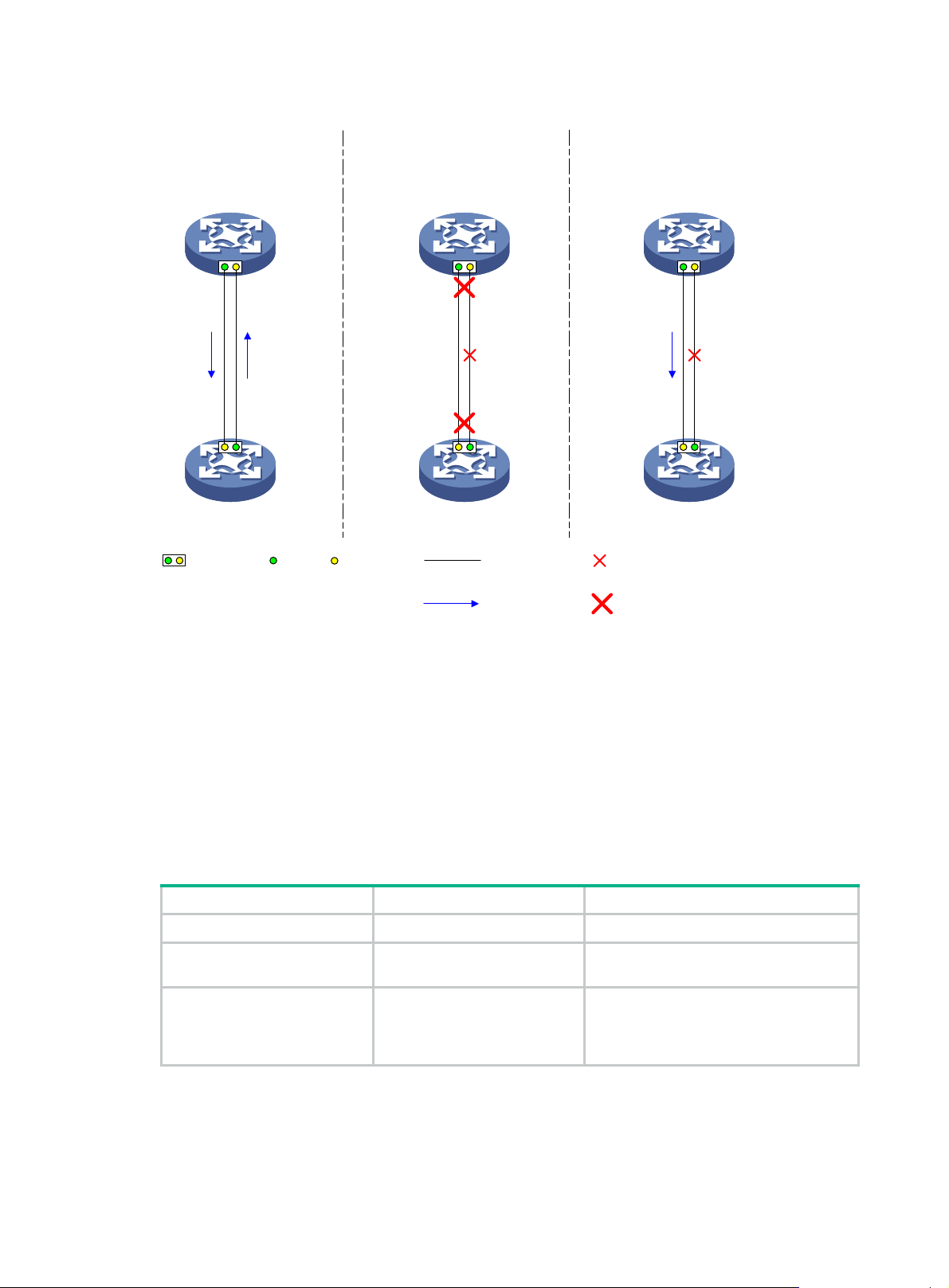
Figure 1 Forcibly bring up a fiber port
Correct fiber
connection
Device A
Device B
Fiber port Tx end Rx end The fiber is disconnected.Fiber link
When Ethernet interfaces
cannot be or are not forcibly
brought up
Device A
Device B
When Ethernet interfaces
are forcibly brought up
Device A
Device B
Configuration restrictions and guidelines
When you forcibly bring up a fiber port, follow these restrictions and guidelines:
• The loopback, shutdown, and port up-mode commands are mutually exclusive.
• The following operations on a fiber port will cause link updown events before the port finally
stays up:
{ Configure both the port up-mode command and the speed or duplex command.
{ Install or remove fiber links or transceiver modules after you forcibly bring up the fiber port.
Configuration procedure
To forcibly bring up a fiber port:
Step Command Remarks
1. Enter system view.
2. Enter Ethernet interface
view.
3. Forcibly bring up the fiber
port.
system-view
interface
interface-number
port up-mode
interface-type
The interface is down.Packets
N/A
N/A
By default, a fiber port is not forcibly
brought up, and the physical state of a
fiber port depends on the physical state
of the fibers.
13
Page 24

Setting the MDIX mode of an Ethernet interface
IMPORTANT:
Fiber ports do not support the MDIX mode setting.
A physical Ethernet interface has eight pins, each of which plays a dedicated role. For example, pins
1 and 2 transmit signals, and pins 3 and 6 receive signals. You can use both crossover and
straight-through Ethernet cables to connect copper Ethernet interfaces. To accommodate these
types of cables, a copper Ethernet interface can operate in one of the following Medium Dependent
Interface-Crossover (MDIX) modes:
• MDIX mode—Pins 1 and 2 are receive pins and pins 3 and 6 are transmit pins.
• MDI mode—Pins 1 and 2 are transmit pins and pins 3 and 6 are receive pins.
• AutoMDIX mode—The interface negotiates pin roles with its peer.
NOTE:
This feature does not take effect on pins 4, 5, 7, and 8 of physical Ethernet interfaces.
• Pins 4, 5, 7, and 8 of interfaces operating at 10 Mbps or 100 Mbps do not receive or transmit
signals.
• Pins 4, 5, 7, and 8 of interfaces operating at 1000 Mbps or higher rates receive and transmit
signals.
To enable a copper Ethernet interface to communicate with its peer, set the MDIX mode of the
interface by following these guidelines:
• Typically, set the MDIX mode of the interface to AutoMDIX. Set the MDIX mode of the interface
to MDI or MDIX only when the device cannot determine the cable type.
• When a straight-through cable is used, configure the interface to operate in an MDIX mode
different than its peer.
• When a crossover cable is used, perform one of the following tasks:
{ Configure the interface to operate in the same MDIX mode as its peer.
{ Configure either end to operate in AutoMDIX mode.
To set the MDIX mode of an Ethernet interface:
Step Command Remarks
1. Enter system view.
2. Enter Ethernet interface
view.
3. Set the MDIX mode of the
Ethernet interface.
system-view
interface
interface-number
mdix-mode { automdix | mdi |
mdix
interface-type
}
N/A
N/A
By default, a copper Ethernet
interface operates in auto mode to
negotiate pin roles with its peer.
10-GE interfaces support only the
automdix
mode.
Testing the cable connection of an Ethernet interface
IMPORTANT:
If the link of an Ethernet interface is up, testing its cable connection will cause the link to go down
and then come up.
14
Page 25
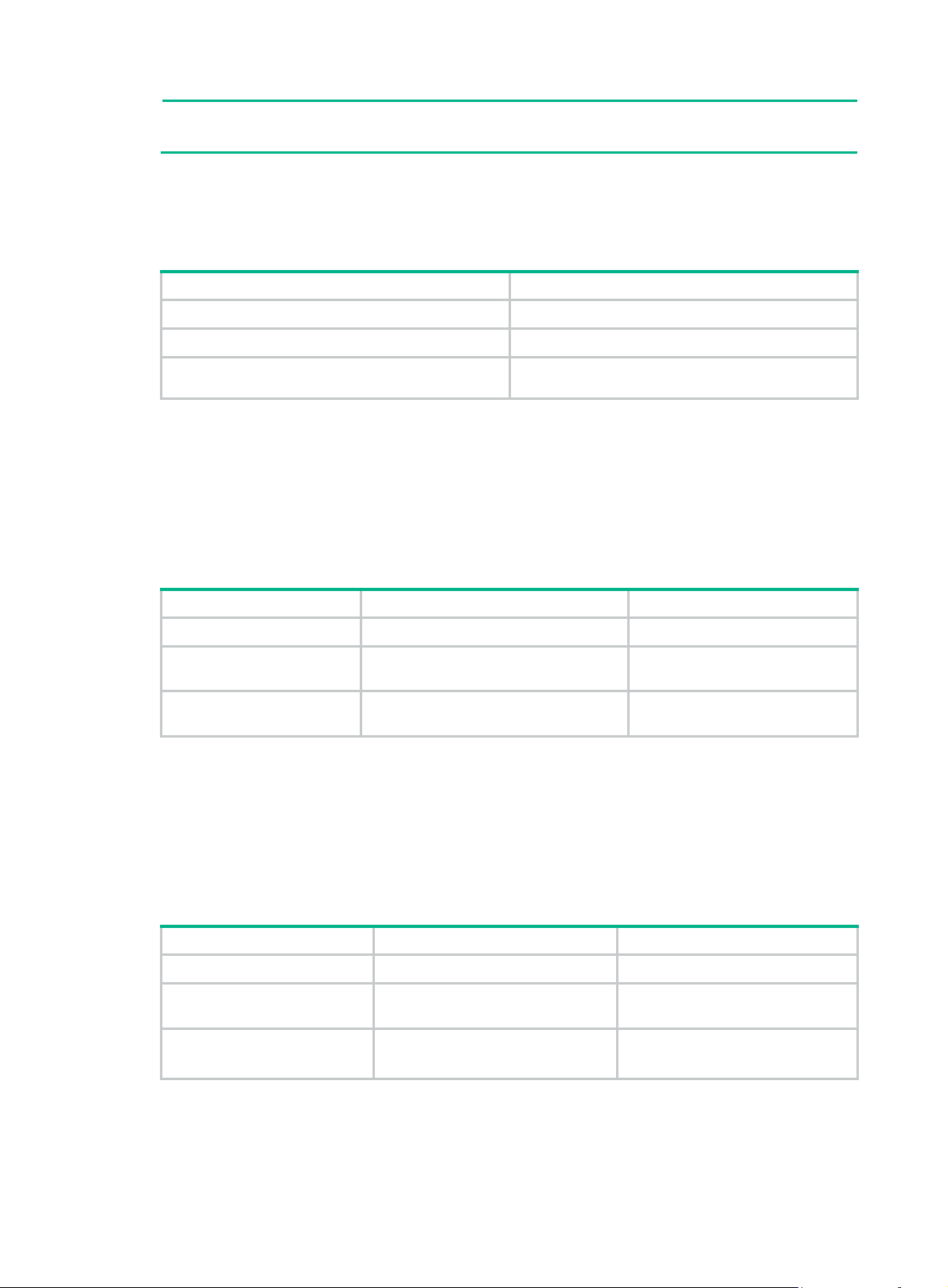
NOTE:
Fiber ports do not support this feature.
This feature tests the cable connection of an Ethernet interface and displays cable test result within 5
seconds. The test result includes the cable's status and some physical parameters. If any fault is
detected, the test result shows the length from the local port to the faulty point.
To test the cable connection of an Ethernet interface:
Step Command
1. Enter system view.
2. Enter Ethernet interface view.
3. Perform a test for the cable connected to the
Ethernet interface.
system-view
interface
virtual-cable-test
interface-type interface-number
Enabling bridging on an Ethernet interface
By default, the device drops packets whose outgoing interface and incoming interface are the same.
To enable the device to forward such packets rather than drop them, enable the bridging feature in
Ethernet interface view.
To enable bridging on an Ethernet interface:
Step Command Remarks
1. Enter system view.
2. Enter Ethernet interface
view.
3. Enable bridging on the
Ethernet interface.
system-view
interface
interface-number
port bridge enable
interface-type
Setting the interface connection distance
When two directly connected interfaces communicate, they use the buffer area to buffer the received
data. A longer interface connection distance requires a greater buffer area.
Perform this task to modify the buffer area size by setting the interface connection distance.
To set the interface connection distance:
Step Command Remarks
1. Enter system view.
2. Enter Layer 2 Ethernet
interface view.
3. Set the interface
connection distance.
system-view
interface
interface-number
port connection-distance
10000
interface-type
|
20000
|
40000
}
{
300
|
N/A
N/A
By default, bridging is disabled on
an Ethernet interface.
N/A
N/A
By default, the interface connection
distance is 10000 meters.
15
Page 26

Configuring a Layer 3 Ethernet interface or subinterface
Setting the MTU for an Ethernet interface or subinterface
The maximum transmission unit (MTU) of an Ethernet interface affects the fragmentation and
reassembly of IP packets on the interface. Typically, you do not need to modify the MTU of an
interface.
To set the MTU for an Ethernet interface or subinterface:
Step Command Remarks
1. Enter system view.
2. Enter Ethernet interface
or subinterface view.
3. Set the MTU of the
Ethernet interface or
subinterface.
Setting the MAC address of an Ethernet interface or
system-view
interface
interface-number.subnumber }
mtu
interface-type { interface-number |
size
N/A
N/A
The default setting is 1500
bytes.
subinterface
In a network, when the Layer 3 Ethernet interfaces or subinterfaces of different devices have the
same MAC address, the devices might fail to communicate correctly. To eliminate the MAC address
conflicts, use the mac-address command to modify the MAC addresses of Layer 3 Ethernet
interfaces or subinterfaces.
Do not configure this feature on the border gateways in the following networks:
• A VXLAN IP gateway network.
• An EVPN gateway network.
To set the MAC address of an Ethernet interface or subinterface:
Step Command Remarks
1. Enter system view.
2. Enter Ethernet interface or
subinterface view.
3. Set the MAC address of the
Ethernet interface or
subinterface.
system-view
interface
{ interface-number |
interface-number.subnumber
}
mac-address
interface-type
mac-address
N/A
N/A
By default, no MAC address is set for
a Layer 3 Ethernet interface or
subinterface.
Displaying and maintaining an Ethernet interface or subinterface
Execute display commands in any view and reset commands in user view.
16
Page 27

Task Command
display counters { inbound | outbound } interface
Display interface traffic statistics.
[ interface-type [ interface-number |
interface-number.subnumber ] ]
Display traffic rate statistics of interfaces
in up state over the last statistics polling
interval.
Display the operational and status
information of the specified interfaces.
Display information about dropped
packets on the specified interfaces.
Display the PFC information for an
interface.
Display information about storm control
on the specified interfaces.
Display the Ethernet module statistics.
Clear interface or subinterface statistics.
Clear the statistics of dropped packets
on the specified interfaces.
Clear the Ethernet module statistics.
display counters rate { inbound | outbound } interface
[ interface-type [ interface-number |
interface-number.subnumber ] ]
display interface
[ interface-type [ interface-number |
interface-number.subnumber ] ] [
display packet-drop { interface
brief
description
[
[ interface-type
down
|
[ interface-number | interface-number.subnumber ] ] |
summary
display priority-flow-control interface
[ interface-number ] ]
}
[ interface-type
display storm-constrain [ broadcast | multicast | unicast ]
interface
[
interface-type interface-number
display ethernet statistics slot
reset counters interface
[ interface-type [ interface-number |
slot-number
]
interface-number.subnumber ] ]
reset packet-drop interface
[ interface-type [ interface-number
| interface-number.subnumber ] ]
reset ethernet statistics
[
slot
slot-number ]
] ]
17
Page 28

Configuring loopback, null, and inloopback interfaces
This chapter describes how to configure a loopback interface, a null interface, and an inloopback
interface.
Configuring a loopback interface
A loopback interface is a virtual interface. The physical layer state of a loopback interface is always
up unless the loopback interface is manually shut down. Because of this benefit, loopback interfaces
are widely used in the following scenarios:
• Configuring a loopback interface address as the source address of the IP packets that
the device generates—Because loopback interface addresses are stable unicast addresses,
they are usually used as device identifications.
{ When you configure a rule on an authentication or security server to permit or deny packets
that a device generates, you can simplify the rule by configuring it to permit or deny packets
carrying the loopback interface address that identifies the device.
{ When you use a loopback interface address as the source address of IP packets, make
sure the route from the loopback interface to the peer is reachable by performing routing
configuration. All data packets sent to the loopback interface are considered packets sent to
the device itself, so the device does not forward these packets.
• Using a loopback interface in dynamic routing protocols—With no router ID configured for
a dynamic routing protocol, the system selects the highest loopback interface IP address as the
router ID. In BGP, to avoid interruption of BGP sessions due to physical port failure, you can use
a loopback interface as the source interface of BGP packets.
To configure a loopback interface:
Step Command Remarks
1. Enter system view.
2. Create a loopback interface
and enter loopback interface
view.
3. Configure the interface
description.
4. Configure the expected
bandwidth of the loopback
interface.
5. Restore the default settings
for the loopback interface.
6. Bring up the loopback
interface.
system-view
interface loopback
interface-number
description
bandwidth
default
undo shutdown
text
bandwidth-value
Configuring a null interface
A null interface is a virtual interface and is always up, but you cannot use it to forward data packets or
configure it with an IP address or link layer protocol. The null interface provides a simpler way to filter
packets than ACL. You can filter undesired traffic by transmitting it to a null interface instead of
N/A
N/A
The default setting is interface name
Interface
Interface
By default, the expected bandwidth
of a loopback interface is 0 kbps.
N/A
By default, a loopback interface is
up.
(for example,
).
LoopBack1
18
Page 29

applying an ACL. For example, if you specify a null interface as the next hop of a static route to a
network segment, any packets routed to the network segment are dropped.
To configure a null interface:
Step Command Remarks
1. Enter system view.
2. Enter null interface view.
3. Configure the interface
description.
4. Restore the default settings
for the null interface.
system-view
interface null 0
description
default
text
N/A
Interface Null 0 is the default null
interface on the device and cannot
be manually created or removed.
Only one null interface, Null 0, is
supported on the device. The null
interface number is always 0.
The default setting is NULL0
Interface.
N/A
Configuring an inloopback interface
An inloopback interface is a virtual interface created by the system, which cannot be configured or
deleted. The physical layer and link layer protocol states of an inloopback interface are always up. All
IP packets sent to an inloopback interface are considered packets sent to the device itself and are
not forwarded.
Displaying and maintaining loopback, null, and inloopback interfaces
Execute display commands in any view and reset commands in user view.
Task Command
Display information about the specified or all
loopback interfaces.
Display information about the null interface.
Display information about the inloopback
interface.
Clear the statistics on the specified or all loopback
interfaces.
Clear the statistics on the null interface.
display interface loopback
description
[
display interface null
down
] ]
display interface inloopback
down
|
reset counters interface loopback
[ interface-number ]
reset counters interface null
down
|
] ]
[ interface-number ] [
] ]
brief
[ 0 ] [
[
[ 0 ] [
[ 0 ]
description
brief
description
[
|
brief
19
Page 30

Bulk configuring interfaces
You can enter interface range view to bulk configure multiple interfaces with the same feature instead
of configuring them one by one. For example, you can execute the shutdown command in interface
range view to shut down a range of interfaces.
Configuration restrictions and guidelines
When you bulk configure interfaces in interface range view, follow these restrictions and guidelines:
• In interface range view, only commands supported by the first interface in the specified interface
list are available for configuration.
• Before you configure an interface as the first interface in an interface range, make sure you can
enter the view of the interface by using the interface interface-type { interface-number |
interface-number.subnumber } command.
• Do not assign both an aggregate interface and any of its member interfaces to an interface
range. Some commands, after being executed on both an aggregate interface and its member
interfaces, can break up the aggregation.
• Understand that the more interfaces you specify in an interface range, the longer the command
execution time.
• To guarantee bulk interface configuration performance, configure fewer than 1000 interface
range names.
• After a command is executed in interface range view, one of the following situations might
occur:
{ The system displays an error message and stays in interface range view. It means that the
execution failed on one or multiple member interfaces.
− If the execution failed on the first member interface, the command is not executed on
any member interfaces.
− If the execution failed on a non-first member interface, the command takes effect on the
remaining member interfaces.
{ The system returns to system view. It means that:
− The command is supported in both system view and interface view.
− The execution failed on a member interface in interface range view and succeeded in
system view.
− The command is not executed on the subsequent member interfaces.
You can use the display this command to verify the configuration in interface view of each
member interface. In addition, if the configuration in system view is not needed, use the
undo form of the command to remove the configuration.
Configuration procedure
Step Command Remarks
1. Enter system view.
system-view
N/A
20
Page 31

Step Command Remarks
• interface range
{ interface-type
2. Enter interface range
view.
3. (Optional.) Display
commands available for
the first interface in the
interface range.
4. Use available
commands to configure
the interfaces.
5. (Optional.) Verify the
configuration.
interface-number [ to
interface-type
interface-number ] } &<1-24>
• interface range name name
[ interface { interface-type
interface-number [ to
interface-type
interface-number ] } &<1-24> ]
Enter a question mark (?) at the
interface range prompt.
Available commands depend on
the interface.
display this
By using the
command, you assign a name to an
interface range and can specify this
name rather than the interface range
to enter the interface range view.
N/A
N/A
N/A
interface range name
Displaying and maintaining bulk interface configuration
Execute the display command in any view.
Task Command
Display information about the interface ranges
created by using the
command.
interface range name
display interface range [ name
name ]
21
Page 32

Configuring the MAC address table
Overview
An Ethernet device uses a MAC address table to forward frames. A MAC address entry includes a
destination MAC address, an outgoing interface, and a VLAN ID. When the device receives a frame,
it uses the destination MAC address of the frame to look for a match in the MAC address table.
• The device forwards the frame out of the outgoing interface in the matching entry if a match is
found.
• The device floods the frame in the VLAN of the frame if no match is found.
How a MAC address entry is created
The entries in the MAC address table include entries automatically learned by the device and entries
manually added.
MAC address learning
The device can automatically populate its MAC address table by learning the source MAC addresses
of incoming frames on each interface.
The device performs the following operations to learn the source MAC address of incoming packets:
1. Checks the source MAC address (for example, MAC-SOURCE) of the frame.
2. Looks up the source MAC address in the MAC address table.
{ The device updates the entry if an entry is found.
{ The device adds an entry for MAC-SOURCE and the incoming port if no entry is found.
When the device receives a frame destined for MAC-SOURCE after learning this source MAC
address, the device performs the following operations:
1. Finds the MAC-SOURCE entry in the MAC address table.
2. Forwards the frame out of the port in the entry.
The device performs the learning process for each incoming frame with an unknown source MAC
address until the table is fully populated.
Manually configuring MAC address entries
Dynamic MAC address learning does not distinguish between illegitimate and legitimate frames,
which can invite security hazards. When Host A is connected to port A, a MAC address entry will be
learned for the MAC address of Host A (for example, MAC A). When an illegal user sends frames
with MAC A as the source MAC address to port B, the device performs the following operations:
1. Learns a new MAC address entry with port B as the outgoing interface and overwrites the old
entry for MAC A.
2. Forwards frames destined for MAC A out of port B to the illegal user.
As a result, the illegal user obtains the data of Host A. To improve the security for Host A, manually
configure a static entry to bind Host A to port A. Then, the frames destined for Host A are always sent
out of port A. Other hosts using the forged MAC address of Host A cannot obtain the frames destined
for Host A.
Types of MAC address entries
A MAC address table can contain the following types of entries:
22
Page 33

• Static entries—A static entry is manually added to forward frames with a specific destination
MAC address out of the associated interface, and it never ages out. A static entry has higher
priority than a dynamically learned one.
• Dynamic entries—A dynamic entry can be manually configured or dynamically learned to
forward frames with a specific destination MAC address out of the associated interface. A
dynamic entry might age out. A manually configured dynamic entry has the same priority as a
dynamically learned one.
• Blackhole entries—A blackhole entry is manually configured and never ages out. A blackhole
entry is configured for filtering out frames with a specific source or destination MAC address.
For example, to block all frames destined for or sourced from a user, you can configure the
MAC address of the user as a blackhole MAC address entry. A blackhole entry has higher
priority than a dynamically learned one.
• Multiport unicast entries—A multiport unicast entry is manually added to send frames with a
specific unicast destination MAC address out of multiple ports, and it never ages out. A multiport
unicast entry has higher priority than a dynamically learned one.
A static, blackhole, or multiport unicast MAC address entry can overwrite a dynamic MAC address
entry, but not vice versa. A static entry, a blackhole entry, and a multiport unicast entry cannot
overwrite one another.
Multiport unicast MAC address entries have no impact on the MAC address learning. When
receiving a frame whose source MAC address matches a multiport unicast entry, the device can still
learn the MAC address of the frame and generate a dynamic entry. However, the generated dynamic
entry has lower priority. The device prefers to use the multiport unicast entry to forward frames
destined for the MAC address in the entry.
MAC address table configuration task list
The configuration tasks discussed in the following sections can be performed in any order.
This document covers only the configuration of unicast MAC address entries, including static,
dynamic, blackhole, and multiport unicast MAC address entries. For information about configuring
static multicast MAC address entries, see IP Multicast Configuration Guide.
To configure the MAC address table, perform the following tasks:
Tasks at a glance
(Optional.) Configuring MAC address entries
• Adding or modifying a static or dynamic MAC address entry globally
• Adding or modifying a static or dynamic MAC
• Adding or modifying a blackhole MAC address entry
• Adding or modifying a multiport unicast MAC address entry
(Optional.) Disabling MAC address learning
(Optional.) Setting the aging timer for dynamic MAC address entries
(Optional.) Setting the MAC learning limit
(Optional.) Configuring the unknown frame forwarding rule after the MAC learning limit is reached
(Optional.) Assigning MAC learning priority to interfaces
(Optional.) Enabling MAC address synchronization
address entry on an interface
(Optional.) Configuring MAC address move notifications and suppression
(Optional.) Enabling ARP fast update for MAC address moves
(Optional.) Disabling static source check
23
Page 34

Tasks at a glance
(Optional.) Enabling conversational remote MAC learning
(Optional.) Enabling SNMP notifications for the MAC address table
Configuring MAC address entries
Configuration guidelines
• A manually configured dynamic MAC address entry will overwrite a learned entry that already
exists with a different outgoing interface for the MAC address.
• The manually configured static, blackhole, and multiport unicast MAC address entries cannot
survive a reboot if you do not save the configuration. The manually configured dynamic MAC
address entries are lost upon reboot whether or not you save the configuration.
A frame whose source MAC address matches different types of MAC address entries is processed
differently.
Type Description
Static MAC address entry
Multiport unicast MAC
address entry
Forwards the frame according to the destination MAC address regardless of
whether the frame's ingress interface is the same as that in the entry.
• Learns the MAC address (MACA) of the frame and generates a dynamic
MAC address entry, but the generated dynamic MAC address entry does
not take effect.
• Forwards frames destined for MACA based on the multiport unicast MAC
address entry.
Blackhole MAC address
entry
Dynamic MAC address
entry
Drops the frame.
• Learns the MAC address of the frames received on a different interface
from that in the entry and overwrites the original entry.
• Forwards the frame received on the same interface as that in the entry
and updates the aging timer for the entry.
Adding or modifying a static or dynamic MAC address entry globally
Step Command Remarks
1. Enter system view.
2. Add or modify a static or
dynamic MAC address entry.
system-view
mac-address { dynamic | static }
mac-address
interface-type interface-number
vlan
vlan-id
interface
N/A
By default, no MAC address entry
is configured globally.
Make sure you have created the
VLAN and assigned the interface
to the VLAN.
24
Page 35

Adding or modifying a static or dynamic MAC address entry on an interface
Step Command Remarks
1. Enter system view.
2. Enter interface view.
3. Add or modify a static or
dynamic MAC address entry.
system-view
• Enter Layer 2 Ethernet
interface view:
interface interface-type
interface-number
• Enter Layer 2 aggregate
interface view:
interface
bridge-aggregation
interface-number
mac-address { dynamic | static }
mac-address
vlan
vlan-id
N/A
N/A
By default, no MAC address entry
is configured on the interface.
Make sure you have created the
VLAN and assigned the interface
to the VLAN.
Adding or modifying a blackhole MAC address entry
Step Command Remarks
1. Enter system view.
2. Add or modify a blackhole
MAC address entry.
system-view
mac-address blackhole
mac-address
vlan
vlan-id
N/A
By default, no blackhole MAC
address entry is configured.
Make sure you have created the
VLAN.
Adding or modifying a multiport unicast MAC address entry
You can configure a multiport unicast MAC address entry to associate a unicast destination MAC
address with multiple ports. The frame with a destination MAC address matching the entry is sent out
of multiple ports.
For example, in NLB unicast mode (see Figure 2):
• All servers within a cluster uses the cluster's MAC address as their own address.
• Frames destined for the cluster are forwarded to every server in the group.
In this case, you can configure a multiport unicast MAC address entry on the device connected to the
server group. Then, the device forwards the frame destined for the server group to every server
through all ports connected to the servers within the cluster.
25
Page 36

Figure 2 NLB cluster
You can configure a multiport unicast MAC address entry globally or on an interface.
Configuring a multiport unicast MAC address entry globally
Step Command Remarks
1. Enter system view.
2. Add or modify a multiport
unicast MAC address entry.
system-view
mac-address multiport
mac-address
interface-list
interface
vlan
vlan-id
N/A
By default, no multiport unicast
MAC address entry is configured
globally.
Make sure you have created the
VLAN and assigned the interface
to the VLAN.
Configuring a multiport unicast MAC address entry on an interface
Step Command Remarks
1. Enter system view.
2. Enter interface view.
system-view
• Enter Layer 2 Ethernet
interface view:
interface interface-type
interface-number
• Enter Layer 2 aggregate
interface view:
interface
bridge-aggregation
interface-number
N/A
N/A
3. Add the interface to a
multiport unicast MAC
address entry.
mac-address multiport
mac-address
vlan
vlan-id
Disabling MAC address learning
MAC address learning is enabled by default. To prevent the MAC address table from being saturated
when the device is experiencing attacks, disable MAC address learning. For example, you can
disable MAC address learning to prevent the device from being attacked by a large amount of frames
with different source MAC addresses.
26
By default, no multiport unicast
MAC address entry is configured
on the interface.
Make sure you have created the
VLAN and assigned the interface
to the VLAN.
Page 37

After MAC address learning is disabled, the device immediately deletes existing dynamic MAC
address entries.
Disabling global MAC address learning
Global MAC address learning does not take effect on a VXLAN VSI. For information about VXLAN
VSIs, see VXLAN Configuration Guide.
To disable global MAC address learning:
Step Command Remarks
1. Enter system view.
2. Disable global MAC address
learning.
system-view
undo mac-address
mac-learning enable
N/A
By default, global MAC address
learning is enabled.
Disabling MAC address learning on interfaces
When global MAC address learning is enabled, you can disable MAC address learning on a single
interface.
To disable MAC address learning on an interface:
Step Command Remarks
1. Enter system view.
2. Enter interface view.
3. Disable MAC address
learning on the interface.
system-view
• Enter Layer 2 Ethernet interface
view:
interface interface-type
interface-number
• Enter Layer 2 aggregate
interface view:
interface bridge-aggregation
interface-number
undo mac-address mac-learning
enable
Disabling MAC address learning on a VLAN
When global MAC address learning is enabled, you can disable MAC address learning on a
per-VLAN basis.
To disable MAC address learning on a VLAN:
Step Command Remarks
1. Enter system view.
2. Enable global MAC address
learning.
3. Enter VLAN view.
4. Disable MAC address
learning on the VLAN.
system-view
mac-address mac-learning
enable
vlan
vlan-id N/A
undo mac-address
mac-learning enable
N/A
By default, global MAC address
learning is enabled.
By default, MAC address learning
on the VLAN is enabled.
N/A
N/A
By default, MAC address
learning on the interface is
enabled.
27
Page 38

Setting the aging timer for dynamic MAC address entries
For security and efficient use of table space, the MAC address table uses an aging timer for each
dynamic MAC address entry. If a dynamic MAC address entry is not updated before the aging timer
expires, the device deletes the entry. This aging mechanism ensures that the MAC address table can
promptly update to accommodate latest network topology changes.
A stable network requires a longer aging interval, and an unstable network requires a shorter aging
interval.
An aging interval that is too long might cause the MAC address table to retain outdated entries. As a
result, the MAC address table resources might be exhausted, and the MAC address table might fail
to update its entries to accommodate the latest network changes.
An interval that is too short might result in removal of valid entries, which would cause unnecessary
floods and possibly affect the device performance.
To reduce floods on a stable network, set a long aging timer or disable the timer to prevent dynamic
entries from unnecessarily aging out. Reducing floods improves the network performance. Reducing
flooding also improves the security because it reduces the chances for a data frame to reach
unintended destinations.
To set the aging timer for dynamic MAC address entries:
Step Command Remarks
1. Enter system view.
2. Set the aging timer for
dynamic MAC address
entries.
system-view
mac-address timer
seconds |
no-aging
aging
{
}
Setting the MAC learning limit
This feature limits the MAC address table size. A large MAC address table will degrade forwarding
performance.
To set the MAC learning limit on an interface:
Step Command Remarks
1. Enter system view.
2. Enter interface view.
3. Set the MAC learning limit on
the interface.
system-view
• Enter Layer 2 Ethernet
interface view:
interface interface-type
interface-number
• Enter Layer 2 aggregate
interface view:
interface
bridge-aggregation
interface-number
mac-address max-mac-count
count
N/A
The default setting is 300
seconds.
no-aging
The
the aging timer.
N/A
N/A
By default, the MAC address table
size is not limited on an interface.
keyword disables
28
Page 39

Configuring the unknown frame forwarding rule after the MAC learning limit is reached
You can enable or disable forwarding of unknown frames after the MAC learning limit is reached.
To configure the device to forward unknown frames received on the interface after the MAC learning
limit on the interface is reached:
Step Command Remarks
1. Enter system view.
2. Enter interface view.
3. Configure the device to
forward unknown frames
received on the interface
after the MAC learning limit
on the interface is reached.
system-view
• Enter Layer 2 Ethernet
interface view.
interface interface-type
interface-number
• Enter Layer 2 aggregate
interface view.
interface
bridge-aggregation
interface-number
mac-address max-mac-count
enable-forwarding
N/A
N/A
By default, the device can forward
unknown frames received on an
interface after the MAC learning
limit on the interface is reached.
Assigning MAC learning priority to interfaces
The MAC learning priority mechanism assigns either low priority or high priority to an interface. An
interface with high priority can learn MAC addresses as usual. However, an interface with low priority
is not allowed to learn MAC addresses already learned on a high-priority interface.
The MAC learning priority mechanism can help defend your network against MAC address spoofing
attacks. In a network that performs MAC-based forwarding, an upper layer device MAC address
might be learned by a downlink interface because of a loop or attack to the downlink interface. To
avoid this issue, perform the following tasks:
• Assign high MAC learning priority to an uplink interface.
• Assign low MAC learning priority to a downlink interface.
To assign MAC learning priority to an interface:
Step Command Remarks
1. Enter system view.
2. Enter interface view.
3. Assign MAC learning priority
to the interface.
system-view
• Enter Layer 2 Ethernet interface
view:
interface interface-type
interface-number
• Enter Layer 2 aggregate
interface view:
interface bridge-aggregation
interface-number
mac-address mac-learning priority
high
{
low
|
}
N/A
N/A
By default, low MAC learning
priority is used.
29
Page 40

Enabling MAC address synchronization
To avoid unnecessary floods and improve forwarding speed, make sure all member devices have the
same MAC address table. After you enable MAC address synchronization, each member device
advertises learned MAC address entries to other member devices.
As shown in Figure 3:
• Device
• Device A and Device B connect to AP C and AP D, respectively.
When Client A associates with AP C, Device A learns a MAC address entry for Client A and
advertises it to Device B.
Figure 3 MAC address tables of devices when Client A accesses AP C
A and Device B form an IRF fabric enabled with MAC address synchronization.
When Client A roams to AP D, Device B learns a MAC address entry for Client A. Device B
advertises it to Device A to ensure service continuity for Client A, as shown in Figure 4.
30
Page 41

Figure 4 MAC address tables of devices when Client A roams to AP D
To enable MAC address synchronization:
Step Command Remarks
1. Enter system view.
2. Enable MAC address
synchronization.
system-view
mac-address mac-roaming
enable
N/A
By default, MAC address
synchronization is disabled.
Configuring MAC address move notifications and suppression
The outgoing interface for a MAC address entry learned on interface A is changed to interface B
when the following conditions exist:
• Interface B receives a packet with the MAC address as the source MAC address.
• Interface B belongs to the same VLAN as interface A.
In this case, the MAC address is moved from interface A to interface B, and a MAC address move
occurs.
The MAC address move notifications feature enables the device to output MAC address move logs
when MAC address moves are detected.
If a MAC address is continuously moved between the two interfaces, Layer 2 loops might occur. To
detect and locate loops, you can view the MAC address move information. To display the MAC
address move records after the device is started, use the display mac-address mac-move
command.
If the system detects that MAC address moves occur frequently on an interface, you can configure
MAC address move suppression to shut the interface down. The interface automatically goes up
after a suppression interval. Or, you can manually bring up the interface.
The MAC address move suppression feature must work with the ARP fast update for MAC address
moves feature. For information about ARP fast update for MAC address moves, see "Enabling ARP
fast update fo
r MAC address moves."
31
Page 42

To configure MAC address move notifications and MAC address move suppression:
Step Command Remarks
1. Enter system view.
2. Enable MAC address move
notifications and optionally
specify a MAC move
detection interval.
system-view
mac-address notification
mac-move [ interval
N/A
interval ]
By default, MAC address move
notifications are disabled.
If you do not specify a detection
interval, the default setting of 1
minute is used.
After you execute this command, the
system sends only log messages to
the information center module. If the
device is also configured with the
snmp-agent trap enable
mac-address
system also sends SNMP
notifications to the SNMP module.
command, the
3. (Optional.) Set MAC
address move suppression
parameters.
4. Enter interface view.
5. Enable MAC address move
suppression.
6. Return to system view.
7. Enable ARP fast update for
MAC address moves.
mac-address notification
mac-move suppression
interval
{
threshold }
• Enter Layer 2 Ethernet
• Enter Layer 2 aggregate
mac-address notification
mac-move suppression
quit
mac-address mac-move
fast-update
interval |
interface view:
interface interface-type
interface-number
interface view:
interface
bridge-aggregation
interface-number
threshold
By default, the suppression interval
is 30 seconds, and the suppression
threshold is 3.
N/A
By default, MAC address move
suppression is disabled.
N/A
By default, ARP fast update for MAC
address moves is disabled.
Enabling ARP fast update for MAC address moves
ARP fast update for MAC address moves allows the device to update an ARP entry immediately after
the outgoing interface for a MAC address changes. This feature ensures data connection without
interruption.
As shown in Figure 5, a mobile u
ser laptop accesses the network by connecting to AP 1 or AP 2.
When the AP to which the user connects changes, the switch updates the ARP entry for the user
immediately after it detects a MAC address move.
32
Page 43

Figure 5 ARP fast update application scenario
Switch
XGE1/0/1 XGE1/0/2
AP 1 AP 2
Laptop
To enable ARP fast update for MAC address moves:
Step Command Remarks
1. Enter system view.
2. Enable ARP fast update for
MAC address moves.
system-view
mac-address mac-move
fast-update
Disabling static source check
By default, the static source check feature is enabled on an interface. The check identifies whether a
received frame meets the following conditions:
• The source MAC address of the frame matches a static MAC address entry.
• The incoming interface of the frame is different from the outgoing interface in the entry.
If the frame meets both conditions, the device drops the frame.
When this feature is disabled, the device does not perform the check for a received frame. It can
forward the frame whether or not the frame meets the conditions.
To disable the static source check feature:
N/A
By default, ARP fast update for
MAC address moves is disabled.
Step Command Remarks
1. Enter system view.
system-view
33
N/A
Page 44

Step Command Remarks
• Enter Layer 2 Ethernet interface
view:
interface interface-type
interface-number
• Enter Layer 2 aggregate
interface view:
interface bridge-aggregation
interface-number
• Enter Layer 3 Ethernet interface
view:
2. Enter interface view.
3. Disable the static source
check feature.
interface interface-type
interface-number
• Enter Layer 3 aggregate
interface/subinterface view:
interface route-aggregation
{ interface-number |
interface-number.subnumber }
• Enter IRF physical interface
view:
interface interface-type
interface-number
undo mac-address static
source-check enable
N/A
By default, the static source
check feature is enabled.
Enabling conversational remote MAC learning
This feature is available only on EVPN networks. Do not enable this feature on non-EVPN networks.
By default, when the device receives a packet from an unknown MAC address of a remote EVPN
network site, the device directly generates a remote MAC address entry. When this feature is
enabled, the device will generate a remote MAC address entry only when the entry is used for packet
forwarding. This feature saves memory resources of the device.
To enable conversational remote MAC learning:
Step Command Remarks
1. Enter system view.
2. Enable conversational
remote MAC learning.
system-view
mac-address
forwarding-conversational-learning
N/A
By default, conversational
remote MAC learning is
disabled.
Enabling SNMP notifications for the MAC address table
To report critical MAC address move events to an NMS, enable SNMP notifications for the MAC
address table. For MAC address move event notifications to be sent correctly, you must also
configure SNMP on the device.
When SNMP notifications are disabled for the MAC address table, the device sends the generated
logs to the information center. To display the logs, configure the log destination and output rule
configuration in the information center.
34
Page 45

For more information about SNMP and information center configuration, see the network
management and monitoring configuration guide for the device.
To enable SNMP notifications for the MAC address table:
Step Command Remarks
1. Enter system view.
2. Enable SNMP
notifications for the
MAC address table.
system-view
snmp-agent trap enable
mac-address [ mac-move
N/A
By default, SNMP notifications are enabled
for the MAC address table.
When SNMP notifications are disabled for the
]
MAC address table, syslog messages are
sent to notify important events on the MAC
address table module.
Displaying and maintaining the MAC address table
Execute display commands in any view.
Task Command
Display MAC address table
information.
display mac-address
static
multiport
interface
] [
] [
interface-type interface-number ] | blackhole |
vlan
vlan-id ] [
[ mac-address [
count
] ]
vlan
vlan-id ] | [ [
dynamic
|
Display the aging timer for dynamic
MAC address entries.
Display the system or interface MAC
address learning state.
Display MAC address statistics.
Display the MAC address move
records.
display mac-address aging-time
display mac-address mac-learning [ interface
interface-number ]
display mac-address statistics
display mac-address mac-move
slot
[
slot-number ]
interface-type
MAC address table configuration example
Network requirements
As shown in Figure 6:
• Host A at MAC address 000f-e235-dc71 is connected to Ten-GigabitEthernet 1/0/1 of Device
and belongs to VLAN 1.
• Host B at MAC address 000f-e235-abcd, which behaved suspiciously on the network, also
belongs to VLAN 1.
Configure the MAC address table as follows:
• To prevent MAC address spoofing, add a static entry for Host A in the MAC address table of
Device.
• To drop all frames destined for Host B, add a blackhole MAC address entry for Host B.
• Set the aging timer to 500 seconds for dynamic MAC address entries.
35
Page 46

Figure 6 Network diagram
Configuration procedure
# Add a static MAC address entry for MAC address 000f-e235-dc71 on Ten-GigabitEthernet 1/0/1
that belongs to VLAN 1.
<Device> system-view
[Device] mac-address static 000f-e235-dc71 interface ten-gigabitethernet 1/0/1 vlan 1
# Add a blackhole MAC address entry for MAC address 000f-e235-abcd that belongs to VLAN 1.
[Device] mac-address blackhole 000f-e235-abcd vlan 1
# Set the aging timer to 500 seconds for dynamic MAC address entries.
[Device] mac-address timer aging 500
Verifying the configuration
# Display the static MAC address entries for Ten-GigabitEthernet 1/0/1.
[Device] display mac-address static interface ten-gigabitethernet 1/0/1
MAC Address VLAN ID State Port/NickName Aging
000f-e235-dc71 1 Static XGE1/0/1 N
# Display the blackhole MAC address entries.
[Device] display mac-address blackhole
MAC Address VLAN ID State Port/NickName Aging
000f-e235-abcd 1 Blackhole N/A N
# Display the aging time of dynamic MAC address entries.
[Device] display mac-address aging-time
MAC address aging time: 500s.
36
Page 47

Configuring MAC Information
The MAC Information feature can generate syslog messages or SNMP notifications when MAC
address entries are learned or deleted. You can use these messages to monitor user's leaving or
joining the network and analyze network traffic.
The MAC Information feature buffers the MAC change syslog messages or SNMP notifications in a
queue. The device overwrites the oldest MAC address change written into the queue with the most
recent MAC address change when the following conditions exist:
• The MAC change notification interval does not expire.
• The queue has been exhausted.
To send a syslog message or SNMP notification immediately after it is created, set the queue length
to zero.
Enabling MAC Information
Step Command Remarks
1. Enter system view.
2. Enable MAC Information
globally.
3. Enter Layer 2 Ethernet
interface view.
system-view
mac-address information enable
interface
interface-number
interface-type
N/A
By default, MAC Information is
globally disabled.
N/A
By default, MAC Information is
4. Enable MAC Information on
the interface.
mac-address information enable
added | deleted
{
}
disabled on the interface.
Make sure you have enabled
MAC Information globally before
you enable it on the interface.
Configuring the MAC Information mode
The following MAC Information modes are available for sending MAC address changes:
• Syslog—The device sends syslog messages to notify MAC address changes. The device
sends syslog messages to the information center, which then outputs them to the monitoring
terminal. For more information about information center, see Network Management and
Monitoring Configuration Guide.
• Trap—The device sends SNMP notifications to notify MAC address changes. The device sends
SNMP notifications to the NMS. For more information about SNMP, see Network Management
and Monitoring Configuration Guide.
To configure the MAC Information mode:
Step Command Remarks
1. Enter system view.
2. Configure the MAC
Information mode.
system-view
mac-address information mode
syslog
{
|
trap
}
N/A
The default setting is
trap
.
37
Page 48

Setting the MAC change notification interval
To prevent syslog messages or SNMP notifications from being sent too frequently, you can set the
MAC change notification interval to a larger value.
To set the MAC change notification interval:
Step Command Remarks
1. Enter system view.
2. Set the MAC change
notification interval.
system-view
mac-address information
interval
interval
N/A
The default setting is 1 second.
Setting the MAC Information queue length
Step Command Remarks
1. Enter system view.
2. Set the MAC Information
queue length.
system-view
mac-address information
queue-length
value
N/A
The default setting is 50.
MAC Information configuration example
Network requirements
Enable MAC Information on Ten-GigabitEthernet 1/0/1 on Device in Figure 7 to send MAC address
changes in syslog messages to the log host, Host B, through interface Ten-GigabitEthernet 1/0/2.
Figure 7 Network diagram
Configuration restrictions and guidelines
When you edit the file /etc/syslog.conf, follow these restrictions and guidelines:
• Comments must be on a separate line and must begin with a pound sign (#).
• No redundant spaces are allowed after the file name.
• The logging facility name and the severity level specified in the /etc/syslog.conf file must be
the same as those configured on the device. Otherwise, the log information might not be output
38
Page 49

correctly to the log host. The logging facility name and the severity level are configured by using
the info-center loghost and info-center source commands, respectively.
Configuration procedure
1. Configure Device to send syslog messages to Host B:
# Enable the information center.
<Device> system-view
[Device] info-center enable
# Specify the log host 192.168.1.2/24 and specify local4 as the logging facility.
[Device] info-center loghost 192.168.1.2 facility local4
# Disable log output to the log host.
[Device] info-center source default loghost deny
To avoid output of unnecessary information, disable all modules from outputting logs to the
specified destination (loghost, in this example) before you configure an output rule.
# Configure an output rule to output to the log host MAC address logs that have a severity level
no lower than informational.
[Device] info-center source mac loghost level informational
2. Configure the log host, Host B:
Configure Solaris as follows. Configure other UNIX operating systems in the same way Solaris
is configured.
a. Log in to the log host as a root user.
b. Create a subdirectory named Device in directory /var/log/.
# mkdir /var/log/Device
c. Create file info.log in the Device directory to save logs from Device.
# touch /var/log/Device/info.log
d. Edit the file syslog.conf in directory /etc/ and add the following contents:
# Device configuration messages
local4.info /var/log/Device/info.log
In this configuration, local4 is the name of the logging facility that the log host uses to
receive logs, and info is the informational level. The UNIX system records the log
information that has a severity level no lower than informational to the file
/var/log/Device/info.log.
e. Display the process ID of syslogd, end the syslogd process, and then restart syslogd
using the –r option to make the new configuration take effect.
# ps -ae | grep syslogd
147
# kill -HUP 147
# syslogd -r &
The device can output MAC address logs to the log host, which stores the logs to the specified
file.
3. Enable MAC Information on Device:
# Enable MAC Information globally.
[Device] mac-address information enable
# Configure the MAC Information mode as syslog.
[Device] mac-address information mode syslog
# Enable MAC Information on Ten-GigabitEthernet 1/0/1 to enable the port to record MAC
address change information when the interface performs either of the following operations:
39
Page 50

{ Learns a new MAC address.
{ Deletes an existing MAC address.
[Device] interface ten-gigabitethernet 1/0/1
[Device-Ten-GigabitEthernet1/0/1] mac-address information enable added
[Device-Ten-GigabitEthernet1/0/1] mac-address information enable deleted
[Device-Ten-GigabitEthernet1/0/1] quit
# Set the MAC Information queue length to 100.
[Device] mac-address information queue-length 100
# Set the MAC change notification interval to 20 seconds.
[Device] mac-address information interval 20
40
Page 51

Configuring Ethernet link aggregation
Ethernet link aggregation bundles multiple physical Ethernet links into one logical link, called an
aggregate link.
Link aggregation has the following benefits:
• Increased bandwidth beyond the limits of any single link. In an aggregate link, traffic is
distributed across the member ports.
• Improved link reliability. The member ports dynamically back up one another. When a member
port fails, its traffic is automatically switched to other member ports.
As shown in Figure 8, Device
physical Ethernet links are combined into an aggregate link called link aggregation 1. The bandwidth
of this aggregate link can reach up to the total bandwidth of the three physical Ethernet links. At the
same time, the three Ethernet links back up one another. When a physical Ethernet link fails, the
traffic previously transmitted on the failed link is switched to the other two links.
Figure 8 Ethernet link aggregation diagram
A and Device B are connected by three physical Ethernet links. These
Basic concepts
Aggregation group, member port, and aggregate interface
An aggregation group is a group of Ethernet interfaces bundled together. These Ethernet interfaces
are called member ports of the aggregation group. Each aggregation group has a corresponding
logical interface (called an aggregate interface).
When an aggregate interface is created, the device automatically creates an aggregation group of
the same type and number as the aggregate interface.
An aggregate interface can be one of the following types:
• Layer 2—A Layer 2 aggregate interface is created manually. The member ports of the
corresponding Layer 2 aggregation group can only be Layer 2 Ethernet interfaces.
• Layer 3—A Layer 3 aggregate interface is created manually. The member ports of the
corresponding Layer 3 aggregation group can only be Layer 3 Ethernet interfaces.
On a Layer 3 aggregate interface, you can create subinterfaces.
The port rate of an aggregate interface equals the total rate of its Selected member ports. Its duplex
mode is the same as that of the Selected member ports. For more information about Selected
member ports, see "Aggregation states of member p
orts in an aggregation group."
Aggregation states of member ports in an aggregation group
A member port in an aggregation group can be in any of the following aggregation states:
• Selected—A Selected port can forward traffic.
• Unselected—An Unselected port cannot forward traffic.
• Individual—An Individual port can forward traffic as a normal physical port. A port is placed in
the Individual state when the following conditions exist:
41
Page 52

{ Its aggregate interface is configured as an edge aggregate interface.
{ The port has not received Link Aggregation Control Protocol Data Units (LACPDUs) from its
peer port.
Operational key
When aggregating ports, the system automatically assigns each port an operational key based on
port information, such as port rate and duplex mode. Any change to this information triggers a
recalculation of the operational key.
In an aggregation group, all Selected ports have the same operational key.
Configuration types
Port configurations include attribute configurations and protocol configurations. Attribute
configurations of a link aggregation member port affect its aggregation state.
• Attribute configurations—To become a Selected port, a member port must have the same
attribute configurations as the aggregate interface. Table 2 de
configurations.
Attribute configurations made on an aggregate interface are automatically synchronized to all
member ports. These configurations are retained on the member ports even after the aggregate
interface is deleted.
Any attribute configuration change on a member port might affect the aggregation states and
running services of the member ports. The system displays a warning message every time you
try to change an attribute configuration setting on a member port.
scribes the attribute
Table 2 Attribute configurations
Feature Considerations
Port isolation
QinQ
VLAN mapping
VLAN
Indicates whether the port has joined an isolation group and which isolation
group the port belongs to.
QinQ status (enabled/disabled), TPID for VLAN tags, and VLAN
transparent transmission. For information about QinQ, see "Configuring
QinQ."
VLAN mapping configured on the port. For more information about VLAN
mapping, see "Configuring VLAN mapping."
VLAN attribute configurations include the following:
• Permitted VLAN IDs.
• PVID.
• Link type (trunk, hybrid, or access).
• PVLAN port type (promiscuous, trunk promiscuous, host, or trunk
secondary).
• IP subnet-based VLAN configuration.
• Protocol-based VLAN configuration.
• VLAN tagging mode.
For information about VLANs, see "Configuring VLANs."
• Protocol configurations—Protocol configurations of a member port do not affect the
aggregation state of the member port. MAC address learning and spanning tree settings are
examples of protocol configurations.
42
Page 53

NOTE:
• The protocol configurations for an aggregate interface take effect only on the current
aggregate interface.
• The protocol configurations for a member port take effect only when the port leaves its
aggregation group.
Link aggregation modes
An aggregation group operates in one of the following modes:
• Static—Static aggregation is stable. An aggregation group in static mode is called a static
aggregation group. The aggregation states of the member ports in a static aggregation group
are not affected by the peer ports.
• Dynamic—An aggregation group in dynamic mode is called a dynamic aggregation group. The
local system and the peer system automatically maintain the aggregation states of the member
ports. Dynamic link aggregation reduces the administrators' workload.
Aggregating links in static mode
Choosing a reference port
When setting the aggregation states of the ports in an aggregation group, the system automatically
chooses a member port as the reference port. A Selected port must have the same operational key
and attribute configurations as the reference port.
The system chooses a reference port from the member ports in up state.
The candidate reference ports are organized into different priority levels following these rules:
1. In descending order of port priority.
2. Full duplex.
3. In descending order of speed.
4. Half duplex.
5. In descending order of speed.
From the candidate ports with the same attribute configurations as the aggregate interface, the one
with the highest priority level is chosen as the reference port.
• If multiple ports have the same priority level, the port that has been Selected (if any) is chosen.
If multiple ports with the same priority level have been Selected, the one with the smallest port
number is chosen.
• If multiple ports have the same priority level and none of them has been Selected, the port with
the smallest port number is chosen.
Setting the aggregation state of each member port
After the reference port is chosen, the system sets the aggregation state of each member port in the
static aggregation group.
43
Page 54

Figure 9 Setting the aggregation state of a member port in a static aggregation group
After the limit on Selected ports is reached, the aggregation state of a new member port varies by
following conditions:
• The port is placed in Unselected state if the port and the Selected ports have the same port
priority. This mechanism prevents traffic interruption on the existing Selected ports. A device
reboot can cause the device to recalculate the aggregation states of member ports.
• The port is placed in Selected state when the following conditions are met:
{ The port and the Selected ports have different port priorities, and the port has a higher port
priority than a minimum of one Selected port.
{ The port has the same attribute configurations as the aggregate interface.
Any operational key or attribute configuration change might affect the aggregation states of link
aggregation member ports.
Aggregating links in dynamic mode
Dynamic aggregation is implemented through IEEE 802.3ad Link Aggregation Control Protocol
(LACP).
44
Page 55

LACP
LACP uses LACPDUs to exchange aggregation information between LACP-enabled devices. Each
member port in a dynamic aggregation group can exchange information with its peer. When a
member port receives an LACPDU, it compares the received information with information received
on the other member ports. In this way, the two systems reach an agreement on which ports are
placed in Selected state.
LACP functions
LACP offers basic LACP functions and extended LACP functions, as described in Table 3.
Table 3 Basic and extended LACP functions
Category Description
Basic LACP functions
Extended LACP
functions
Implemented through the basic LACPDU fields, including the system LACP
priority, system MAC address, port priority, port number, and operational key.
Implemented by extending the LACPDU with new TLV fields. Extended LACP can
implement LACP MAD for the IRF feature.
The switch series can participate in LACP MAD as either an IRF member device or
an intermediate device.
For more information about IRF and the LACP MAD mechanism, see IRF
Configuration Guide.
LACP operating modes
LACP can operate in active or passive mode.
When LACP is operating in passive mode on a local member port and its peer port, both ports cannot
send LACPDUs. When LACP is operating in active mode on either end of a link, both ports can send
LACPDUs.
LACP priorities
LACP priorities include system LACP priority and port priority, as described in Table 4. The smaller
the priority value, the higher the priority.
Table 4 LACP priorities
Type Description
System LACP
priority
Port priority
LACP timeout interval
Used by two peer devices (or systems) to determine which one is superior in link
aggregation.
In dynamic link aggregation, the system that has higher system LACP priority sets
the Selected state of member ports on its side. The system that has lower priority
sets the aggregation state of local member ports the same as their respective peer
ports.
Determines the likelihood of a member port to be a Selected port on a system. A port
with a higher port priority is more likely to become Selected.
The LACP timeout interval specifies how long a member port waits to receive LACPDUs from the
peer port. If a local member port has not received LACPDUs from the peer within the LACP timeout
interval, the member port considers the peer as failed.
The LACP timeout interval also determines the LACPDU sending rate of the peer. LACP timeout
intervals include the following types:
• Short timeout interval—3 seconds. If you use the short timeout interval, the peer sends one
LACPDU per second.
45
Page 56

• Long timeout interval—90 seconds. If you use the long timeout interval, the peer sends one
LACPDU every 30 seconds.
How dynamic link aggregation works
Choosing a reference port
The system chooses a reference port from the member ports in up state. A Selected port must have
the same operational key and attribute configurations as the reference port.
The local system (the actor) and the peer system (the partner) negotiate a reference port by using
the following workflow:
1. The two systems determine the system with the smaller system ID.
A system ID contains the system LACP priority and the system MAC address.
a. The two systems compare their LACP priority values.
The lower the LACP priority, the smaller the system ID. If the LACP priority values are the
same, the two systems proceed to step b.
b. The two systems compare their MAC addresses.
The lower the MAC address, the smaller the system ID.
2. The system with the smaller system ID chooses the port with the smallest port ID as the
reference port.
A port ID contains a port priority and a port number. The lower the port priority, the smaller the
port ID.
a. The system chooses the port with the lowest priority value as the reference port.
If the ports have the same priority, the system proceeds to step b.
b. The system compares their port numbers.
The smaller the port number, the smaller the port ID.
The port with the smallest port number and the same attribute configurations as the
aggregate interface is chosen as the reference port.
Setting the aggregation state of each member port
After the reference port is chosen, the system with the smaller system ID sets the state of each
member port on its side.
46
Page 57

Figure 10 Setting the state of a member port in a dynamic aggregation group
The system with the greater system ID can detect the aggregation state changes on the peer system.
The system with the greater system ID sets the aggregation state of local member ports the same as
their peer ports.
When you aggregate interfaces in dynamic mode, follow these guidelines:
• A dynamic link aggregation group chooses only full-duplex ports as the Selected ports.
• For stable aggregation and service continuity, do not change the operational key or attribute
configurations on any member port.
• After the Selected port limit is reached, a newly joining port becomes a Selected port if it is more
eligible than a current Selected port.
47
Page 58

Edge aggregate interface
Dynamic link aggregation fails on a server-facing aggregate interface if dynamic link aggregation is
configured only on the device. The device forwards traffic by using only one of the physical ports that
are connected to the server.
To improve link reliability, configure the aggregate interface as an edge aggregate interface. This
feature enables all member ports of the aggregation group to forward traffic. When a member port
fails, its traffic is automatically switched to other member ports.
After dynamic link aggregation is configured on the server, the device can receive LACPDUs from
the server. Then, link aggregation between the device and the server operates correctly.
An edge aggregate interface takes effect only when it is configured on an aggregate interface
corresponding to a dynamic aggregation group.
Load sharing modes for link aggregation groups
In a link aggregation group, traffic can be load shared across the Selected ports based on any of the
following modes:
• Per-flow load sharing—Load shares traffic on a per-flow basis. The load sharing mode
classifies packets into flows and forwards packets of the same flow on the same link. This mode
can be one or any combination of the following traffic classification criteria:
{ Ingress port.
{ Source or destination IP address.
{ Source or destination MAC address.
{ Source or destination port number.
• Packet type-based load sharing—Load shares traffic automatically based on packet types
(Layer 2 protocol, IPv4, or IPv6).
Ethernet link aggregation configuration task list
Tasks at a glance
(Required.) Configuring an aggregation group:
• Configuring a Layer 2 aggregation group
• Configuring a Layer 3 aggregation group
(Optional.) Configuring an aggregate interface:
• Configuring the description of an ag
• Setting the MAC address for an aggregate interface
• Specifying ignored VLANs for a Layer 2 aggregate interface
• Setting the MTU for a Layer 3 aggregate interface
• Setting the minimum and maximum numbers of Selected ports for an aggregation group
• Setting the expected bandwidth for an aggregate interface
• Configuring an edge aggregate interface
• Enabling BFD for an aggregation group
• Shutting down an aggregate interface
• Restoring the default settings for an aggregate interface
gregate interface
48
Page 59

Tasks at a glance
(Optional.) Configuring load sharing for link aggregation groups:
• Setting load sharing modes for link aggregation groups
• Enabling local-first load sharing for link aggregation
• Configuring link aggregation load sharing algorithm settings
• Setting the global load sharing mode for MAC-in-MAC traffic
(Optional.) Enabling link-aggregation traffic redirection
(Optional.) Forwarding the traffic of specified VLANs out of a fixed member port on an aggregate link
(Optional.) Excluding a subnet from load sharing on aggregate links
Configuring an aggregation group
This section explains how to configure an aggregation group.
Configuration restrictions and guidelines
When you configure an aggregation group, follow these restrictions and guidelines:
• Table 5 sh
ows the interfaces that cannot be assigned to a Layer 2 aggregation group.
Table 5 Interfaces that cannot be assigned to a Layer 2 aggregation group
Interface type Reference
Interface configured with MAC
authentication
Interface configured with port security Port security in Security Configuration Guide
Interface configured with 802.1X 802.1X in Security Configuration Guide
• Do not assign a reflector port for port mirroring to an aggregation group. For more information
about reflector ports, see Network Management and Monitoring Configuration Guide.
• Deleting an aggregate interface also deletes its aggregation group and causes all member
ports to leave the aggregation group.
• You must configure the same aggregation mode on the two ends of an aggregate link.
• For a successful static aggregation, make sure the ports at both ends of each link are in the
same aggregation state.
• For a successful dynamic aggregation, make sure the peer ports of the ports aggregated at one
end are also aggregated. The two ends can automatically negotiate the aggregation state of
each member port.
MAC authentication in Security Configuration Guide
Configuring a Layer 2 aggregation group
Configuring a Layer 2 static aggregation group
Step Command Remarks
1. Enter system view.
system-view
49
N/A
Page 60

Step Command Remarks
2. Create a Layer 2 aggregate
interface and enter Layer 2
aggregate interface view.
3. Exit to system view.
4. Assign an interface to the
specified Layer 2
aggregation group.
5. (Optional.) Set the port
priority for the interface.
interface bridge-aggregation
interface-number
quit
a Enter Layer 2 Ethernet
interface view:
interface interface-type
interface-number
b Assign the interface to the
specified Layer 2
aggregation group:
port link-aggregation
group group-id
link-aggregation port-priority
priority
Configuring a Layer 2 dynamic aggregation group
Step Command Remarks
1. Enter system view.
system-view
When you create a Layer 2
aggregate interface, the system
automatically creates a Layer 2
static aggregation group
numbered the same.
N/A
Repeat these two substeps to
assign more Layer 2 Ethernet
interfaces to the aggregation
group.
The default port priority of an
interface is 32768.
N/A
2. Set the system LACP priority.
3. Create a Layer 2 aggregate
interface and enter Layer 2
aggregate interface view.
4. Configure the aggregation
group to operate in dynamic
mode.
5. Exit to system view.
6. Assign an interface to the
specified Layer 2
aggregation group.
7. Set the LACP operating
mode for the interface.
8. Set the port priority for the
interface.
lacp system-priority
interface bridge-aggregation
interface-number
link-aggregation mode dynamic
quit
a Enter Layer 2 Ethernet
interface view:
interface interface-type
interface-number
b Assign the interface to the
specified Layer 2
aggregation group:
port link-aggregation
group group-id
• Set the LACP operating
mode to passive:
lacp mode passive
• Set the LACP operating
mode to active:
undo lacp mode
link-aggregation port-priority
priority
priority
By default, the system LACP
priority is 32768.
Changing the system LACP
priority might affect the
aggregation states of the ports in
a dynamic aggregation group.
When you create a Layer 2
aggregate interface, the system
automatically creates a Layer 2
static aggregation group
numbered the same.
By default, an aggregation group
operates in static mode.
N/A
Repeat these two substeps to
assign more Layer 2 Ethernet
interfaces to the aggregation
group.
By default, LACP is operating in
active mode.
The default setting is 32768.
50
Page 61

Step Command Remarks
9. Set the short LACP timeout
interval (3 seconds) for the
interface.
lacp period short
Configuring a Layer 3 aggregation group
Configuring a Layer 3 static aggregation group
Step Command Remarks
1. Enter system view.
system-view
By default, the long LACP timeout
interval (90 seconds) is used by
the interface.
To avoid traffic interruption during
an ISSU, do not set the short
LACP timeout interval before
performing the ISSU. For more
information about ISSU, see
Fundamentals Configuration
Guide.
N/A
2. Create a Layer 3 aggregate
interface and enter Layer 3
aggregate interface view.
3. Exit to system view.
4. Assign an interface to the
specified Layer 3
aggregation group.
5. (Optional.) Set the port
priority for the interface.
interface route-aggregation
interface-number
quit
a Enter Layer 3 Ethernet
interface view:
interface interface-type
interface-number
b Assign the interface to the
specified Layer 3
aggregation group:
port link-aggregation
group group-id
link-aggregation port-priority
priority
Configuring a Layer 3 dynamic aggregation group
Step Command Remarks
1. Enter system view.
2. Set the system LACP priority.
system-view
lacp system-priority
priority
When you create a Layer 3
aggregate interface, the system
automatically creates a Layer 3
static aggregation group
numbered the same.
N/A
Repeat these two substeps to
assign more Layer 3 Ethernet
interfaces to the aggregation
group.
The default port priority of an
interface is 32768.
N/A
By default, the system LACP
priority is 32768.
Changing the system LACP
priority might affect the
aggregation states of the ports in
the dynamic aggregation group.
3. Create a Layer 3 aggregate
interface and enter Layer 3
aggregate interface view.
interface route-aggregation
interface-number
51
When you create a Layer 3
aggregate interface, the system
automatically creates a Layer 3
static aggregation group
numbered the same.
Page 62

Step Command Remarks
4. Configure the aggregation
group to operate in dynamic
mode.
5. Exit to system view.
6. Assign an interface to the
specified Layer 3
aggregation group.
7. Set the LACP operating
mode for the interface.
8. Set the port priority for the
interface.
link-aggregation mode dynamic
quit
a Enter Layer 3 Ethernet
interface view:
interface interface-type
interface-number
b Assign the interface to the
specified Layer 3
aggregation group:
port link-aggregation
group group-id
• Set the LACP operating
mode to passive:
lacp mode passive
• Set the LACP operating
mode to active:
undo lacp mode
link-aggregation port-priority
priority
By default, an aggregation group
operates in static mode.
N/A
Repeat these two substeps to
assign more Layer 3 Ethernet
interfaces to the aggregation
group.
By default, LACP is operating in
active mode.
The default setting is 32768.
By default, the long LACP timeout
interval (90 seconds) is used by
the interface.
9. Set the short LACP timeout
interval (3 seconds) for the
interface.
lacp period short
To avoid traffic interruption during
an ISSU, do not set the short
LACP timeout interval before
performing the ISSU. For more
information about ISSU, see
Fundamentals Configuration
Guide.
Configuring an aggregate interface
Most configurations that can be made on Layer 2 or Layer 3 Ethernet interfaces can also be made on
Layer 2 or Layer 3 aggregate interfaces.
Configuring the description of an aggregate interface
You can configure the description of an aggregate interface for administration purposes, for example,
describing the purpose of the interface.
To configure the description of an aggregate interface:
Step Command Remarks
1. Enter system view.
system-view
N/A
52
Page 63

Step Command Remarks
• Enter Layer 2 aggregate
interface view:
interface bridge-aggregation
2. Enter aggregate
interface or subinterface
view.
3. Configure the
description of the
aggregate interface or
subinterface.
interface-number
• Enter Layer 3 aggregate
interface or subinterface view:
interface route-aggregation
{ interface-number |
interface-number.subnumber }
description
text
N/A
By default, the description of an
interface is interface-name
Interface
.
Setting the MAC address for an aggregate interface
By default, all aggregate interfaces on a device use the same MAC address, and aggregate
interfaces on different devices use different MAC addresses. Typically, the MAC address of an
aggregate interface is not required to be modified.
Do not set MAC addresses for aggregate interfaces on border gateways in VXLAN or EVPN
networks.
To set the MAC address for an aggregate interface:
Step Command Remarks
1. Enter system view.
2. Enter Layer 3 aggregate
interface or subinterface
view.
3. Set the MAC address for the
aggregate interface or
subinterface.
system-view
interface route-aggregation
{ interface-number |
interface-number.subnumber }
mac-address
mac-address
N/A
N/A
By default, the MAC address of a
Layer 3 aggregate interface or
subinterface is not set.
Specifying ignored VLANs for a Layer 2 aggregate interface
The system ignores the permit state and tagging mode of an ignored VLAN when choosing Selected
ports.
By default, to become Selected, the member ports must have the same VLAN permit state and
tagging mode as the corresponding Layer 2 aggregate interface.
To specify ignored VLANs for a Layer 2 aggregate interface:
Step Command Remarks
1. Enter system view.
2. Enter Layer 2 aggregate
interface view.
system-view
interface bridge-aggregation
interface-number
N/A
N/A
3. Specify ignored VLANs.
link-aggregation ignore vlan
vlan-id-list
53
By default, a Layer 2 aggregate
interface does not ignore any
VLANs.
Page 64

Setting the MTU for a Layer 3 aggregate interface
The MTU of an interface affects IP packets fragmentation and reassembly on the interface.
To set the MTU for a Layer 3 aggregate interface:
Step Command Remarks
1. Enter system view.
2. Enter Layer 3 aggregate
interface or subinterface
view.
3. Set the MTU for the Layer 3
aggregate interface or
subinterface.
system-view
interface route-aggregation
{ interface-number |
interface-number.subnumber }
mtu
size The default setting is 1500 bytes.
N/A
N/A
Setting the minimum and maximum numbers of Selected ports for an aggregation group
IMPORTANT:
The minimum and maximum numbers of Selected ports must be the same for the local and peer
aggregation groups.
The bandwidth of an aggregate link increases as the number of Selected member ports increases.
To avoid congestion, you can set the minimum number of Selected ports required for bringing up an
aggregate interface.
This minimum threshold setting affects the aggregation states of aggregation member ports and the
state of the aggregate interface.
• When the number of member ports eligible to be Selected ports is smaller than the minimum
threshold, the following events occur:
{ The eligible member ports are placed in Unselected state.
{ The link layer state of the aggregate interface becomes down.
• When the number of member ports eligible to be Selected ports reaches or exceeds the
minimum threshold, the following events occur:
{ The eligible member ports are placed in Selected state.
{ The link layer state of the aggregate interface becomes up.
The maximum number of Selected ports allowed in an aggregation group is limited by either manual
configuration or hardware limitation, whichever value is smaller.
You can implement backup between two ports by performing the following tasks:
• Assigning two ports to an aggregation group.
• Setting the maximum number of Selected ports to 1 for the aggregation group.
Then, only one Selected port is allowed in the aggregation group, and the Unselected port acts as a
backup port.
To set the minimum and maximum numbers of Selected ports for an aggregation group:
Step Command Remarks
1. Enter system view.
system-view
N/A
54
Page 65

Step Command Remarks
• Enter Layer 2 aggregate
interface view:
interface
bridge-aggregation
2. Enter aggregate interface
view.
3. Set the minimum number of
Selected ports for the
aggregation group.
4. Set the maximum number of
Selected ports for the
aggregation group.
interface-number
• Enter Layer 3 aggregate
interface view:
interface
route-aggregation
interface-number
link-aggregation selected-port
minimum
link-aggregation selected-port
maximum
min-number
max-number
N/A
By default, the minimum number
of Selected ports is not specified
for an aggregation group.
By default, the maximum number
of Selected ports for an
aggregation group is 32.
Setting the expected bandwidth for an aggregate interface
Step Command Remarks
1. Enter system view.
2. Enter aggregate interface
view.
system-view
• Enter Layer 2 aggregate
interface view:
interface
bridge-aggregation
interface-number
• Enter Layer 3 aggregate
interface or subinterface
view:
interface
route-aggregation
{ interface-number |
interface-number.subnumbe
r }
N/A
N/A
3. Set the expected bandwidth
for the interface.
bandwidth
bandwidth-value
Configuring an edge aggregate interface
When you configure an edge aggregate interface, follow these restrictions and guidelines:
• This configuration takes effect only on the aggregate interface corresponding to a dynamic
aggregation group.
• Link-aggregation traffic redirection does not operate correctly on an edge aggregate interface.
For more information about link-aggregation traffic redirection, see "Enabling link-aggregation
fic redirection."
traf
To configure an edge aggregate interface:
Step Command Remarks
1. Enter system view.
system-view
55
By default, the expected
bandwidth (in kbps) is the
interface baud rate divided by
1000.
N/A
Page 66

Step Command Remarks
• Enter Layer 2 aggregate
interface view:
interface
bridge-aggregation
2. Enter aggregate interface
view.
3. Configure the aggregate
interface as an edge
aggregate interface.
interface-number
• Enter Layer 3 aggregate
interface view:
interface
route-aggregation
interface-number
lacp edge-port
Enabling BFD for an aggregation group
BFD for Ethernet link aggregation can monitor member link status in an aggregation group. After you
enable BFD on an aggregate interface, each Selected port in the aggregation group establishes a
BFD session with its peer port. BFD operates differently depending on the aggregation mode.
• BFD for static aggregation—When BFD detects a link failure, BFD notifies the Ethernet link
aggregation module that the peer port is unreachable. The local port is placed in Unselected
state. The BFD session between the local and peer ports remains, and the local port keeps
sending BFD packets. When the link is recovered, the local port receives BFD packets from the
peer port, and BFD notifies the Ethernet link aggregation module that the peer port is reachable.
The local port is placed in Selected state again. This mechanism ensures that the local and
peer ports of a static aggregate link have the same aggregation state.
• BFD for dynamic aggregation—When BFD detects a link failure, BFD notifies the Ethernet
link aggregation module that the peer port is unreachable. BFD clears the session and stops
sending BFD packets. When the link is recovered and the local port is placed in Selected state
again, the local port establishes a new session with the peer port. BFD notifies the Ethernet link
aggregation module that the peer port is reachable. Because BFD provides fast failure
detection, the local and peer systems of a dynamic aggregate link can negotiate the
aggregation state of their member ports faster.
N/A
By default, an aggregate interface
does not operate as an edge
aggregate interface.
For more information about BFD, see High Availability Configuration Guide.
Configuration restrictions and guidelines
When you enable BFD for an aggregation group, follow these restrictions and guidelines:
• Make sure the source and destination IP addresses are consistent at the two ends of an
aggregate link. For example, if you execute link-aggregation bfd ipv4 source 1.1.1.1
destination 2.2.2.2 on the local end, execute link-aggregation bfd ipv4 source 2.2.2.2
destination 1.1.1.1 on the peer end. The source and destination IP addresses cannot be the
same.
• The BFD parameters configured on an aggregate interface take effect on all BFD sessions in
the aggregation group. BFD sessions for link aggregation do not support the echo packet mode
and the Demand mode.
• As a best practice, do not configure other protocols to collaborate with BFD on a BFD-enabled
aggregate interface.
• Make sure the number of member ports in a BFD-enabled aggregation group is not larger than
the number of BFD sessions supported by the device. Otherwise, this command might cause
some Selected ports in the aggregation group to change to the Unselected state.
56
Page 67

Configuration procedure
To enable BFD for an aggregation group:
Step Command Remarks
1. Enter system view.
2. Enter aggregate interface
view.
3. Enable BFD for the
aggregation group.
system-view
• Enter Layer 2 aggregate interface view:
interface bridge-aggregation
interface-number
• Enter Layer 3 aggregate interface view:
interface route-aggregation
interface-number
link-aggregation bfd ipv4 source
ip-address
destination
ip-address
Shutting down an aggregate interface
N/A
N/A
By default, BFD is disabled
for an aggregation group.
The source and destination
IP addresses of BFD
sessions must be unicast
addresses excluding
0.0.0.0.
Shutting down or bringing up an aggregate interface affects the aggregation states and link states of
member ports in the corresponding aggregation group as follows:
• When an aggregate interface is shut down, all Selected ports in the corresponding aggregation
group become Unselected ports and all member ports go down.
• When an aggregate interface is brought up, the aggregation states of member ports in the
corresponding aggregation group are recalculated.
To shut down an aggregate interface:
Step Command
1. Enter system view.
2. Enter aggregate interface view.
3. Shut down the aggregate interface or
subinterface.
system-view
• Enter Layer 2 aggregate interface view:
interface bridge-aggregation interface-number
• Enter Layer 3 aggregate interface or subinterface view:
interface route-aggregation { interface-number |
interface-number.subnumber }
shutdown
Restoring the default settings for an aggregate interface
You can restore all configurations on an aggregate interface to the default settings.
To restore the default settings for an aggregate interface:
Step Command
1. Enter system view.
system-view
57
Page 68

Step Command
• Enter Layer 2 aggregate interface view:
interface bridge-aggregation interface-number
2. Enter aggregate interface view.
3. Restore the default settings for the
aggregate interface.
• Enter Layer 3 aggregate interface or subinterface view:
interface route-aggregation { interface-number |
interface-number.subnumber }
default
Configuring load sharing for link aggregation groups
This section explains how to configure the load sharing modes for link aggregation groups and how
to enable local-first load sharing for link aggregation.
Setting load sharing modes for link aggregation groups
You can set the global or group-specific load sharing mode. A link aggregation group preferentially
uses the group-specific load sharing mode. If the group-specific load sharing mode is not available,
the group uses the global load sharing mode.
The destination port and source port criteria of the global load sharing mode also take effect on
aggregation groups that have group-specific load sharing settings. If the global load sharing mode
contains one or both of these criteria, these aggregation groups use both the port load sharing
settings and group-specific load sharing settings.
Setting the global link-aggregation load sharing mode
Step Command Remarks
1. Enter system view.
2. Set the global
link-aggregation load
sharing mode.
system-view
link-aggregation global load-sharing
mode
destination-mac
ingress-port
mpls-label2
|
destination-ip
{
source-port
destination-port
|
mpls-label1
|
source-ip
|
} *
|
|
Setting the group-specific load sharing mode
Step Command Remarks
1. Enter system view.
2. Enter aggregate interface
view.
system-view
• Enter Layer 2 aggregate
interface view:
interface bridge-aggregation
interface-number
• Enter Layer 3 aggregate
interface view:
interface route-aggregation
interface-number
|
|
source-mac
N/A
By default, the system load shares
traffic automatically based on
packet types.
N/A
N/A
58
Page 69

Step Command Remarks
link-aggregation load-sharing
3. Set the load sharing mode
for the aggregation group.
mode
destination-mac
source-ip
flexible }
destination-ip
{ {
source-mac
|
|
destination-port
|
} * |
By default, the group-specific
|
load sharing mode is the same
as the global load sharing mode.
Enabling local-first load sharing for link aggregation
Use local-first load sharing in a multidevice link aggregation scenario to distribute traffic preferentially
across member ports on the ingress device.
When you aggregate ports on different member devices in an IRF fabric, you can use local-first load
sharing to reduce traffic on IRF links, as shown in Figure 11. Fo
Configuration Guide.
Figure 11 Load sharing for multidevice link aggregation in an IRF fabric
The egress port for a traffic flow is an
aggregate interface that has Selected
ports on different IRF member devices
r more information about IRF, see IRF
Yes No
Any Selected ports on the
ingress device?
Yes
Packets are load-shared only
across the Selected ports on the
To enable local-first load sharing for link aggregation:
ingress device
Local-first load sharing
mechanism enabled?
No
Packets are load-shared across
all Selected ports
Step Command Remarks
1. Enter system view.
2. Enable local-first load
sharing for link aggregation.
system-view
link-aggregation load-sharing
mode local-first
N/A
By default, local-first load sharing
for link aggregation is enabled.
Configuring link aggregation load sharing algorithm settings
To optimize traffic distribution on aggregate links, you can configure a link aggregation load sharing
algorithm and an algorithm seed. You can set only the algorithm or the algorithm seed, or both. You
can combine an algorithm with different algorithm seeds to obtain different effects.
59
Page 70

This feature takes effect only when the per-flow load sharing mode is used and the per-flow load
sharing mode does not use the following traffic classification criteria:
• Source IP address.
• Destination IP address.
• Source MAC address.
• Destination MAC address.
• Source and destination IP addresses.
• Source and destination MAC addresses.
To configure a link aggregation load sharing algorithm:
Step Command Remarks
1. Enter system view.
2. Configure a link aggregation
load sharing algorithm.
3. Configure a link aggregation
load sharing algorithm seed.
system-view
link-aggregation global
load-sharing algorithm
algorithm-number
link-aggregation global
load-sharing seed
seed-number
N/A
By default, algorithm 5 is used.
If the device fails to load share
traffic flows across all Selected
ports, you can specify algorithm 1
to 13 in sequence until the
problem is solved.
By default, algorithm seed 0 is
used.
Setting the global load sharing mode for MAC-in-MAC traffic
MAC-in-MAC traffic can be load shared based on any of the following items:
• The outer frame header, and source and destination ports.
• The inner frame header, and source and destination ports.
To set the global load sharing mode for MAC-in-MAC traffic:
Step Command Remarks
1. Enter system view.
2. Set the global load sharing
mode for MAC-in-MAC
traffic.
system-view
link-aggregation global
load-sharing minm
outer
}
{
inner
N/A
By default, MAC-in-MAC traffic is
load shared based on the inner
|
frame header, and source and
destination ports.
Enabling link-aggregation traffic redirection
This feature redirects traffic on a Selected port to the remaining available Selected ports of an
aggregation group if one of the following events occurs:
• The port is shut down by using the shutdown command.
• The slot that hosts the port reboots, and the aggregation group spans multiple slots.
This feature ensures zero packet loss for known unicast traffic, but does not protect unknown unicast
traffic.
You can enable link-aggregation traffic redirection globally or for an aggregation group. Global
link-aggregation traffic redirection settings take effect on all aggregation groups. A link aggregation
group preferentially uses the group-specific link-aggregation traffic redirection settings. If
60
Page 71

group-specific link-aggregation traffic redirection is not configured, the group uses the global
link-aggregation traffic redirection settings.
Configuration restrictions and guidelines
When you enable link-aggregation traffic redirection, follow these restrictions and guidelines:
• Link-aggregation traffic redirection applies only to dynamic link aggregation groups.
• To prevent traffic interruption, enable link-aggregation traffic redirection on devices at both ends
of the aggregate link.
• To prevent packet loss that might occur when a slot reboots, do not enable spanning tree
together with link-aggregation traffic redirection.
• Link-aggregation traffic redirection does not operate correctly on an edge aggregate interface.
• As a best practice, enable link-aggregation traffic redirection on aggregate interfaces. If you
enable this feature globally, communication with a third-party peer device might be affected if
the peer is not compatible with this feature.
Configuration procedure
To enable link-aggregation traffic redirection globally:
Step Command Remarks
1. Enter system view.
2. Enable link-aggregation
traffic redirection globally.
To enable link-aggregation traffic redirection for an aggregation group:
system-view
link-aggregation lacp
traffic-redirect-notification
enable
N/A
By default, link-aggregation traffic
redirection is disabled globally.
Step Command Remarks
1. Enter system view.
2. Enter aggregate interface
view.
3. Enable link-aggregation
traffic redirection for the
aggregation group.
system-view
• Enter Layer 2 aggregate
interface view:
interface
bridge-aggregation
interface-number
• Enter Layer 3 aggregate
interface view:
interface
route-aggregation
interface-number
link-aggregation lacp
traffic-redirect-notification
enable
N/A
N/A
By default, link-aggregation traffic
redirection is disabled for an
aggregation group.
Forwarding the traffic of specified VLANs out of a fixed member port on an aggregate link
To forward the traffic in specific VLANs out of a fixed port on an aggregate link, specify those VLANs
as management VLANs and specify that port as a management port.
61
Page 72

This task excludes the traffic in the specified VLANs from the load sharing mechanism on the
aggregate link.
An aggregation group can have only one management port. If you specify multiple ports in an
aggregation group as management ports, the system chooses the port with the lowest port number
as the management port.
To forward the traffic in specific VLANs out of a fixed port on an aggregate link:
Step Command Remarks
1. Enter system view.
2. Specify the management
VLANs.
3. Enter Layer 2 Ethernet
interface view.
system-view
link-aggregation
management-vlan
interface
interface-number
N/A
interface-type
vlan-id-list
By default, no management
VLANs exist on aggregate links.
You cannot specify VLAN 1 as a
management VLAN.
If the Layer 2 Ethernet interface is
not an aggregation member port,
the management port setting
takes effect after the interface is
assigned to an aggregation group.
4. Configure the interface as a
management port.
link-aggregation
management-port
By default, an interface does not
act as a management port in its
aggregation group.
Excluding a subnet from load sharing on aggregate links
IMPORTANT:
This feature is available in 2510P01 and later.
Typically, an aggregate interface distributes traffic across its Selected member ports. The uplink and
downlink traffic of a host might be distributed to different member ports, as shown in Figure 12. T
make sure the bidirectional traffic of a subnet traverses the same member port, you can exclude that
subnet from load sharing by specifying it as a link aggregation management subnet.
When an aggregate interface receives an ARP packet from the management subnet, the device
looks up the sender IP address in the ARP table for a matching entry.
• If no matching entry exists, the device creates an ARP entry on the aggregation member port
from which the packet came in. This mechanism ensures that the returned downlink traffic will
be forwarded out of the member port that received the uplink traffic.
• If an ARP entry already exists on a different port than the aggregate interface or its member
ports, the device does not update that ARP entry. Instead, the device broadcasts an ARP
request out of all ports to relearn the ARP entry.
o
When an aggregate interface sends an ARP packet to the management subnet, the device sends
the packet out of all Selected member ports of the aggregate interface.
As shown in Figure 12,
an aggregate link is established between the server and the IRF fabric. The
server sends all uplink traffic of a subnet through Port C1 to Port A1 on the IRF fabric. If that subnet
is not specified as a management subnet, the IRF fabric distributes its downlink traffic across Port A1
and Port B2. To send the downlink traffic of that subnet to the server only through Port A1, you can
specify the subnet as a link aggregation management subnet.
62
Page 73

Figure 12 Link aggregation scenario before management subnets are used
You can configure a maximum of 20 management subnets.
To ensure correct packet forwarding, delete all ARP entries of a subnet before you specify it as a
management subnet or after you remove it from the management subnet list.
If you are using link aggregation management subnets, do not use ARP snooping. For more
information, see Layer 3—IP Services Configuration Guide.
To exclude a subnet from load sharing on aggregate links:
Step Command Remarks
1. Enter system view.
2. Specify a link aggregation
management subnet
system-view
link-aggregation
management-subnet
{ mask | mask-length }
ip-address
N/A
By default, no link aggregation
management subnets are
specified.
Displaying and maintaining Ethernet link aggregation
Execute display commands in any view and reset commands in user view.
Task Command
Display information for an aggregate interface
or multiple aggregate interfaces.
display interface
route-aggregation
description
[
bridge-aggregation
[ {
} [ interface-number ] ] [
down
|
] ]
|
brief
Display the local system ID.
Display the global or group-specific
link-aggregation load sharing modes.
display lacp system-id
display link-aggregation load-sharing mode
bridge-aggregation
[ {
interface-number ] ]
63
route-aggregation
|
[
}
interface
Page 74

Task Command
Display forwarding information for the specified
traffic flow.
display link-aggregation load-sharing path interface
bridge-aggregation
{
interface-number
interface-number [
destination-ipv6
source-ipv6
mac-address |
type-number |
mac-address |
ipv6-address } |
destination-port
ip-protocol
source-port
route-aggregation
|
ingress-port
route
ipv6-address } | {
interface-type
destination-ip
] { {
destination-mac
port-id |
protocol-id |
port-id |
}
source-ip
ethernet-type
source-mac
vlan
vlan-id } *
ip-address |
ip-address |
Display detailed link aggregation information
for link aggregation member ports.
Display summary information about all
aggregation groups.
Display detailed information about the
specified aggregation groups.
Clear LACP statistics for the specified link
aggregation member ports.
Clear statistics for the specified aggregate
interfaces.
display link-aggregation member-port
display link-aggregation summary
display link-aggregation verbose
bridge-aggregation
[ {
[ interface-number ] ]
reset lacp statistics
reset counters interface
route-aggregation
route-aggregation
|
interface
[
bridge-aggregation
[ {
} [ interface-number ] ]
interface-list ]
[ interface-list ]
}
|
Ethernet link aggregation configuration examples
Layer 2 static aggregation configuration example
Network requirements
On the network shown in Figure 13, perform the following tasks:
• Configure a Layer 2 static aggregation group on both Device A and Device B.
• Enable VLAN 10 at one end of the aggregate link to communicate with VLAN 10 at the other
end.
• Enable VLAN 20 at one end of the aggregate link to communicate with VLAN 20 at the other
end.
Figure 13 Network diagram
64
Page 75

Configuration procedure
1. Configure Device A:
# Create VLAN 10, and assign port Ten-GigabitEthernet 1/0/4 to VLAN 10.
<DeviceA> system-view
[DeviceA] vlan 10
[DeviceA-vlan10] port ten-gigabitethernet 1/0/4
[DeviceA-vlan10] quit
# Create VLAN 20, and assign port Ten-GigabitEthernet 1/0/5 to VLAN 20.
[DeviceA] vlan 20
[DeviceA-vlan20] port ten-gigabitethernet 1/0/5
[DeviceA-vlan20] quit
# Create Layer 2 aggregate interface Bridge-Aggregation 1.
[DeviceA] interface bridge-aggregation 1
[DeviceA-Bridge-Aggregation1] quit
# Assign ports Ten-GigabitEthernet 1/0/1 through Ten-GigabitEthernet 1/0/3 to link aggregation
group 1.
[DeviceA] interface ten-gigabitethernet 1/0/1
[DeviceA-Ten-GigabitEthernet1/0/1] port link-aggregation group 1
[DeviceA-Ten-GigabitEthernet1/0/1] quit
[DeviceA] interface ten-gigabitethernet 1/0/2
[DeviceA-Ten-GigabitEthernet1/0/2] port link-aggregation group 1
[DeviceA-Ten-GigabitEthernet1/0/2] quit
[DeviceA] interface ten-gigabitethernet 1/0/3
[DeviceA-Ten-GigabitEthernet1/0/3] port link-aggregation group 1
[DeviceA-Ten-GigabitEthernet1/0/3] quit
# Configure Layer 2 aggregate interface Bridge-Aggregation 1 as a trunk port and assign it to
VLANs 10 and 20.
[DeviceA] interface bridge-aggregation 1
[DeviceA-Bridge-Aggregation1] port link-type trunk
[DeviceA-Bridge-Aggregation1] port trunk permit vlan 10 20
[DeviceA-Bridge-Aggregation1] quit
2. Configure Device B in the same way Device A is configured. (Details not shown.)
Verifying the configuration
# Display detailed information about all aggregation groups on Device A.
[DeviceA] display link-aggregation verbose
Loadsharing Type: Shar -- Loadsharing, NonS -- Non-Loadsharing
Port Status: S -- Selected, U -- Unselected, I -- Individual
Port: A -- Auto port, M -- Management port, R -- Reference port
Flags: A -- LACP_Activity, B -- LACP_Timeout, C -- Aggregation,
D -- Synchronization, E -- Collecting, F -- Distributing,
G -- Defaulted, H -- Expired
Aggregate Interface: Bridge-Aggregation1
Aggregation Mode: Static
Loadsharing Type: NonS
Management VLANs: None
Port Status Priority Oper-Key
65
Page 76

------------------------------------------------------------------------------- XGE1/0/1 S 32768 1
XGE1/0/2 S 32768 1
XGE1/0/3 S 32768 1
The output shows that link aggregation group 1 is a Layer 2 static aggregation group that contains
three Selected ports.
Layer 2 dynamic aggregation configuration example
Network requirements
On the network shown in Figure 14, perform the following tasks:
• Configure a Layer 2 dynamic aggregation group on both Device A and Device B.
• Enable VLAN 10 at one end of the aggregate link to communicate with VLAN 10 at the other
end.
• Enable VLAN 20 at one end of the aggregate link to communicate with VLAN 20 at the other
end.
Figure 14 Network diagram
Configuration procedure
1. Configure Device A:
# Create VLAN 10, and assign the port Ten-GigabitEthernet 1/0/4 to VLAN 10.
<DeviceA> system-view
[DeviceA] vlan 10
[DeviceA-vlan10] port ten-gigabitethernet 1/0/4
[DeviceA-vlan10] quit
# Create VLAN 20, and assign the port Ten-GigabitEthernet 1/0/5 to VLAN 20.
[DeviceA] vlan 20
[DeviceA-vlan20] port ten-gigabitethernet 1/0/5
[DeviceA-vlan20] quit
# Create Layer 2 aggregate interface Bridge-Aggregation 1, and set the link aggregation mode
to dynamic.
[DeviceA] interface bridge-aggregation 1
[DeviceA-Bridge-Aggregation1] link-aggregation mode dynamic
[DeviceA-Bridge-Aggregation1] quit
66
Page 77

# Assign ports Ten-GigabitEthernet 1/0/1 through Ten-GigabitEthernet 1/0/3 to link aggregation
group 1.
[DeviceA] interface ten-gigabitethernet 1/0/1
[DeviceA-Ten-GigabitEthernet1/0/1] port link-aggregation group 1
[DeviceA-Ten-GigabitEthernet1/0/1] quit
[DeviceA] interface ten-gigabitethernet 1/0/2
[DeviceA-Ten-GigabitEthernet1/0/2] port link-aggregation group 1
[DeviceA-Ten-GigabitEthernet1/0/2] quit
[DeviceA] interface ten-gigabitethernet 1/0/3
[DeviceA-Ten-GigabitEthernet1/0/3] port link-aggregation group 1
[DeviceA-Ten-GigabitEthernet1/0/3] quit
# Configure Layer 2 aggregate interface Bridge-Aggregation 1 as a trunk port and assign it to
VLANs 10 and 20.
[DeviceA] interface bridge-aggregation 1
[DeviceA-Bridge-Aggregation1] port link-type trunk
[DeviceA-Bridge-Aggregation1] port trunk permit vlan 10 20
[DeviceA-Bridge-Aggregation1] quit
2. Configure Device B in the same way Device A is configured. (Details not shown.)
Verifying the configuration
# Display detailed information about all aggregation groups on Device A.
[DeviceA] display link-aggregation verbose
Loadsharing Type: Shar -- Loadsharing, NonS -- Non-Loadsharing
Port Status: S -- Selected, U -- Unselected, I -- Individual
Port: A -- Auto port, M -- Management port, R -- Reference port
Flags: A -- LACP_Activity, B -- LACP_Timeout, C -- Aggregation,
D -- Synchronization, E -- Collecting, F -- Distributing,
G -- Defaulted, H -- Expired
Aggregate Interface: Bridge-Aggregation1
Aggregation Mode: Dynamic
Loadsharing Type: NonS
Management VLANs: None
System ID: 0x8000, 000f-e267-6c6a
Local:
Port Status Priority Index Oper-Key Flag
XGE1/0/1 S 32768 11 1 {ACDEF}
XGE1/0/2 S 32768 12 1 {ACDEF}
XGE1/0/3 S 32768 13 1 {ACDEF}
Remote:
Actor Priority Index Oper-Key SystemID Flag
XGE1/0/1 32768 81 1 0x8000, 000f-e267-57ad {ACDEF}
XGE1/0/2 32768 82 1 0x8000, 000f-e267-57ad {ACDEF}
XGE1/0/3 32768 83 1 0x8000, 000f-e267-57ad {ACDEF}
The output shows that link aggregation group 1 is a Layer 2 dynamic aggregation group that contains
three Selected ports.
67
Page 78

Layer 2 aggregation load sharing configuration example
Network requirements
On the network shown in Figure 15, perform the following tasks:
• Configure Layer 2 static aggregation groups 1 and 2 on Device A and Device B, respectively.
• Enable VLAN 10 at one end of the aggregate link to communicate with VLAN 10 at the other
end.
• Enable VLAN 20 at one end of the aggregate link to communicate with VLAN 20 at the other
end.
• Configure link aggregation groups 1 and 2 to load share traffic across aggregation group
member ports.
{ Configure link aggregation group 1 to load share packets based on source MAC addresses.
{ Configure link aggregation group 2 to load share packets based on destination MAC
addresses.
Figure 15 Network diagram
Configuration procedure
1. Configure Device A:
# Create VLAN 10, and assign the port Ten-GigabitEthernet 1/0/5 to VLAN 10.
<DeviceA> system-view
[DeviceA] vlan 10
[DeviceA-vlan10] port ten-gigabitethernet 1/0/5
[DeviceA-vlan10] quit
# Create VLAN 20, and assign the port Ten-GigabitEthernet 1/0/6 to VLAN 20.
[DeviceA] vlan 20
[DeviceA-vlan20] port ten-gigabitethernet 1/0/6
[DeviceA-vlan20] quit
# Create Layer 2 aggregate interface Bridge-Aggregation 1.
[DeviceA] interface bridge-aggregation 1
# Configure Layer 2 aggregation group 1 to load share packets based on source MAC
addresses.
[DeviceA-Bridge-Aggregation1] link-aggregation load-sharing mode source-mac
[DeviceA-Bridge-Aggregation1] quit
# Assign ports Ten-GigabitEthernet 1/0/1 and Ten-GigabitEthernet 1/0/2 to link aggregation
group 1.
68
Page 79

[DeviceA] interface ten-gigabitethernet 1/0/1
[DeviceA-Ten-GigabitEthernet1/0/1] port link-aggregation group 1
[DeviceA-Ten-GigabitEthernet1/0/1] quit
[DeviceA] interface ten-gigabitethernet 1/0/2
[DeviceA-Ten-GigabitEthernet1/0/2] port link-aggregation group 1
[DeviceA-Ten-GigabitEthernet1/0/2] quit
# Configure Layer 2 aggregate interface Bridge-Aggregation 1 as a trunk port and assign it to
VLAN 10.
[DeviceA] interface bridge-aggregation 1
[DeviceA-Bridge-Aggregation1] port link-type trunk
[DeviceA-Bridge-Aggregation1] port trunk permit vlan 10
[DeviceA-Bridge-Aggregation1] quit
# Create Layer 2 aggregate interface Bridge-Aggregation 2.
[DeviceA] interface bridge-aggregation 2
# Configure Layer 2 aggregation group 2 to load share packets based on destination MAC
addresses.
[DeviceA-Bridge-Aggregation2] link-aggregation load-sharing mode destination-mac
[DeviceA-Bridge-Aggregation2] quit
# Assign ports Ten-GigabitEthernet 1/0/3 and Ten-GigabitEthernet 1/0/4 to link aggregation
group 2.
[DeviceA] interface ten-gigabitethernet 1/0/3
[DeviceA-Ten-GigabitEthernet1/0/3] port link-aggregation group 2
[DeviceA-Ten-GigabitEthernet1/0/3] quit
[DeviceA] interface ten-gigabitethernet 1/0/4
[DeviceA-Ten-GigabitEthernet1/0/4] port link-aggregation group 2
[DeviceA-Ten-GigabitEthernet1/0/4] quit
# Configure Layer 2 aggregate interface Bridge-Aggregation 2 as a trunk port and assign it to
VLAN 20.
[DeviceA] interface bridge-aggregation 2
[DeviceA-Bridge-Aggregation2] port link-type trunk
[DeviceA-Bridge-Aggregation2] port trunk permit vlan 20
[DeviceA-Bridge-Aggregation2] quit
2. Configure Device B in the same way Device A is configured. (Details not shown.)
Verifying the configuration
# Display detailed information about all aggregation groups on Device A.
[DeviceA] display link-aggregation verbose
Loadsharing Type: Shar -- Loadsharing, NonS -- Non-Loadsharing
Port Status: S -- Selected, U -- Unselected, I -- Individual
Port: A -- Auto port, M -- Management port, R -- Reference port
Flags: A -- LACP_Activity, B -- LACP_Timeout, C -- Aggregation,
D -- Synchronization, E -- Collecting, F -- Distributing,
G -- Defaulted, H -- Expired
Aggregate Interface: Bridge-Aggregation1
Aggregation Mode: Static
Loadsharing Type: Shar
Management VLANs: None
Port Status Priority Oper-Key
69
Page 80

------------------------------------------------------------------------------- XGE1/0/1 S 32768 1
XGE1/0/2 S 32768 1
Aggregate Interface: Bridge-Aggregation2
Aggregation Mode: Static
Loadsharing Type: Shar
Management VLANs: None
Port Status Priority Oper-Key
------------------------------------------------------------------------------- XGE1/0/3 S 32768 2
XGE1/0/4 S 32768 2
The output shows that:
• Link aggregation groups 1 and 2 are both load-shared Layer 2 static aggregation groups.
• Each aggregation group contains two Selected ports.
# Display all the group-specific load sharing modes on Device A.
[DeviceA] display link-aggregation load-sharing mode interface
Bridge-Aggregation1 Load-Sharing Mode:
source-mac address
Bridge-Aggregation2 Load-Sharing Mode:
destination-mac address
The output shows that:
• Link aggregation group 1 load shares packets based on source MAC addresses.
• Link aggregation group 2 load shares packets based on destination MAC addresses.
Layer 2 edge aggregate interface configuration example
Network requirements
As shown in Figure 16, a Layer 2 dynamic aggregation group is configured on the device. The server
is not configured with dynamic link aggregation.
Configure an edge aggregate interface so that both Ten-GigabitEthernet 1/0/1 and
Ten-GigabitEthernet 1/0/2 can forward traffic to improve link reliability.
Figure 16 Network diagram
Configuration procedure
# Create Layer 2 aggregate interface Bridge-Aggregation 1, and set the link aggregation mode to
dynamic.
<Device> system-view
[Device] interface bridge-aggregation 1
[Device-Bridge-Aggregation1] link-aggregation mode dynamic
70
Page 81

# Configure Layer 2 aggregate interface Bridge-Aggregation 1 as an edge aggregate interface.
[Device-Bridge-Aggregation1] lacp edge-port
[Device-Bridge-Aggregation1] quit
# Assign ports Ten-GigabitEthernet 1/0/1 and Ten-GigabitEthernet 1/0/2 to link aggregation group 1.
[Device] interface ten-gigabitethernet 1/0/1
[Device-Ten-GigabitEthernet1/0/1] port link-aggregation group 1
[Device-Ten-GigabitEthernet1/0/1] quit
[Device] interface ten-gigabitethernet 1/0/2
[Device-Ten-GigabitEthernet1/0/2] port link-aggregation group 1
[Device-Ten-GigabitEthernet1/0/2] quit
Verifying the configuration
# Display detailed information about all aggregation groups on the device when the server is not
configured with dynamic link aggregation.
[Device] display link-aggregation verbose
Loadsharing Type: Shar -- Loadsharing, NonS -- Non-Loadsharing
Port Status: S -- Selected, U -- Unselected, I -- Individual
Port: A -- Auto port, M -- Management port, R -- Reference port
Flags: A -- LACP_Activity, B -- LACP_Timeout, C -- Aggregation,
D -- Synchronization, E -- Collecting, F -- Distributing,
G -- Defaulted, H -- Expired
Aggregate Interface: Bridge-Aggregation1
Aggregation Mode: Dynamic
Loadsharing Type: NonS
Management VLANs: None
System ID: 0x8000, 000f-e267-6c6a
Local:
Port Status Priority Index Oper-Key Flag
XGE1/0/1 I 32768 11 1 {AG}
XGE1/0/2 I 32768 12 1 {AG}
Remote:
Actor Priority Index Oper-Key SystemID Flag
XGE1/0/1 32768 81 0 0x8000, 0000-0000-0000 {DEF}
XGE1/0/2 32768 82 0 0x8000, 0000-0000-0000 {DEF}
The output shows that Ten-GigabitEthernet 1/0/1 and Ten-GigabitEthernet 1/0/2 are in Individual
state when they do not receive LACPDUs from the server. Both Ten-GigabitEthernet 1/0/1 and
Ten-GigabitEthernet 1/0/2 can forward traffic. When one port fails, its traffic is automatically switched
to the other port.
Layer 3 static aggregation configuration example
Network requirements
On the network shown in Figure 17, perform the following tasks:
• Configure a Layer 3 static aggregation group on both Device A and Device B.
• Configure IP addresses and subnet masks for the corresponding Layer 3 aggregate interfaces.
71
Page 82

Figure 17 Network diagram
Configuration procedure
1. Configure Device A:
# Create Layer 3 aggregate interface Route-Aggregation 1, and configure an IP address and
subnet mask for the aggregate interface.
<DeviceA> system-view
[DeviceA] interface route-aggregation 1
[DeviceA-Route-Aggregation1] ip address 192.168.1.1 24
[DeviceA-Route-Aggregation1] quit
# Assign Layer 3 Ethernet interfaces Ten-GigabitEthernet 1/0/1 through Ten-GigabitEthernet
1/0/3 to aggregation group 1.
[DeviceA] interface ten-gigabitethernet 1/0/1
[DeviceA-Ten-GigabitEthernet1/0/1] port link-aggregation group 1
[DeviceA-Ten-GigabitEthernet1/0/1] quit
[DeviceA] interface ten-gigabitethernet 1/0/2
[DeviceA-Ten-GigabitEthernet1/0/2] port link-aggregation group 1
[DeviceA-Ten-GigabitEthernet1/0/2] quit
[DeviceA] interface ten-gigabitethernet 1/0/3
[DeviceA-Ten-GigabitEthernet1/0/3] port link-aggregation group 1
[DeviceA-Ten-GigabitEthernet1/0/3] quit
2. Configure Device B in the same way Device A is configured. (Details not shown.)
Verifying the configuration
# Display detailed information about all aggregation groups on Device A.
[DeviceA] display link-aggregation verbose
Loadsharing Type: Shar -- Loadsharing, NonS -- Non-Loadsharing
Port Status: S -- Selected, U -- Unselected, I -- Individual
Port: A -- Auto port, M -- Management port, R -- Reference port
Flags: A -- LACP_Activity, B -- LACP_Timeout, C -- Aggregation,
D -- Synchronization, E -- Collecting, F -- Distributing,
G -- Defaulted, H -- Expired
Aggregate Interface: Route-Aggregation1
Aggregation Mode: Static
Loadsharing Type: NonS
Management VLANs: None
Port Status Priority Oper-Key
------------------------------------------------------------------------------- XGE1/0/1 S 32768 1
XGE1/0/2 S 32768 1
XGE1/0/3 S 32768 1
The output shows that link aggregation group 1 is a Layer 3 static aggregation group that contains
three Selected ports.
72
Page 83

Layer 3 dynamic aggregation configuration example
Network requirements
On the network shown in Figure 18, perform the following tasks:
• Configure a Layer 3 dynamic aggregation group on both Device A and Device B.
• Configure IP addresses and subnet masks for the corresponding Layer 3 aggregate interfaces.
Figure 18 Network diagram
Configuration procedure
1. Configure Device A:
# Create Layer 3 aggregate interface Route-Aggregation 1.
<DeviceA> system-view
[DeviceA] interface route-aggregation 1
# Set the link aggregation mode to dynamic.
[DeviceA-Route-Aggregation1] link-aggregation mode dynamic
# Configure an IP address and subnet mask for Route-Aggregation 1.
[DeviceA-Route-Aggregation1] ip address 192.168.1.1 24
[DeviceA-Route-Aggregation1] quit
# Assign Layer 3 Ethernet interfaces Ten-GigabitEthernet 1/0/1 through Ten-GigabitEthernet
1/0/3 to aggregation group 1.
[DeviceA] interface ten-gigabitethernet 1/0/1
[DeviceA-Ten-GigabitEthernet1/0/1] port link-aggregation group 1
[DeviceA-Ten-GigabitEthernet1/0/1] quit
[DeviceA] interface ten-gigabitethernet 1/0/2
[DeviceA-Ten-GigabitEthernet1/0/2] port link-aggregation group 1
[DeviceA-Ten-GigabitEthernet1/0/2] quit
[DeviceA] interface ten-gigabitethernet 1/0/3
[DeviceA-Ten-GigabitEthernet1/0/3] port link-aggregation group 1
[DeviceA-Ten-GigabitEthernet1/0/3] quit
2. Configure Device B in the same way Device A is configured. (Details not shown.)
Verifying the configuration
# Display detailed information about all aggregation groups on Device A.
[DeviceA] display link-aggregation verbose
Loadsharing Type: Shar -- Loadsharing, NonS -- Non-Loadsharing
Port Status: S -- Selected, U -- Unselected, I -- Individual
Port: A -- Auto port, M -- Management port, R -- Reference port
Flags: A -- LACP_Activity, B -- LACP_Timeout, C -- Aggregation,
D -- Synchronization, E -- Collecting, F -- Distributing,
G -- Defaulted, H -- Expired
Aggregate Interface: Route-Aggregation1
Aggregation Mode: Dynamic
73
Page 84

Loadsharing Type: NonS
Management VLANs: None
System ID: 0x8000, 000f-e267-6c6a
Local:
Port Status Priority Index Oper-Key Flag
XGE1/0/1 S 32768 11 1 {ACDEF}
XGE1/0/2 S 32768 12 1 {ACDEF}
XGE1/0/3 S 32768 13 1 {ACDEF}
Remote:
Actor Priority Index Oper-Key SystemID Flag
XGE1/0/1 32768 81 1 0x8000, 000f-e267-57ad {ACDEF}
XGE1/0/2 32768 81 1 0x8000, 000f-e267-57ad {ACDEF}
XGE1/0/3 32768 81 1 0x8000, 000f-e267-57ad {ACDEF}
The output shows that link aggregation group 1 is a Layer 3 dynamic aggregation group that contains
three Selected ports.
Layer 3 aggregation load sharing configuration example
Network requirements
On the network shown in Figure 19, perform the following tasks:
• Configure Layer 3 static aggregation groups 1 and 2 on Device A and Device B, respectively.
• Configure IP addresses and subnet masks for the corresponding Layer 3 aggregate interfaces.
• Configure link aggregation group 1 to load share packets based on source IP addresses.
• Configure link aggregation group 2 to load share packets based on destination IP addresses.
Figure 19 Network diagram
Configuration procedure
1. Configure Device A:
# Create Layer 3 aggregate interface Route-Aggregation 1.
<DeviceA> system-view
[DeviceA] interface route-aggregation 1
# Configure Layer 3 aggregation group 1 to load share packets based on source IP addresses.
[DeviceA-Route-Aggregation1] link-aggregation load-sharing mode source-ip
# Configure an IP address and subnet mask for Layer 3 aggregate interface Route-Aggregation
1.
[DeviceA-Route-Aggregation1] ip address 192.168.1.1 24
[DeviceA-Route-Aggregation1] quit
# Assign Layer 3 Ethernet interfaces Ten-GigabitEthernet 1/0/1 and Ten-GigabitEthernet 1/0/2
to aggregation group 1.
[DeviceA] interface ten-gigabitethernet 1/0/1
[DeviceA-Ten-GigabitEthernet1/0/1] port link-aggregation group 1
74
Page 85

[DeviceA-Ten-GigabitEthernet1/0/1] quit
[DeviceA] interface ten-gigabitethernet 1/0/2
[DeviceA-Ten-GigabitEthernet1/0/2] port link-aggregation group 1
[DeviceA-Ten-GigabitEthernet1/0/2] quit
# Create Layer 3 aggregate interface Route-Aggregation 2.
[DeviceA] interface route-aggregation 2
# Configure Layer 3 aggregation group 2 to load share packets based on destination IP
addresses.
[DeviceA-Route-Aggregation2] link-aggregation load-sharing mode destination-ip
# Configure an IP address and subnet mask for Layer 3 aggregate interface Route-Aggregation
2.
[DeviceA-Route-Aggregation2] ip address 192.168.2.1 24
[DeviceA-Route-Aggregation2] quit
# Assign Layer 3 Ethernet interfaces Ten-GigabitEthernet 1/0/3 and Ten-GigabitEthernet 1/0/4
to aggregation group 2.
[DeviceA] interface ten-gigabitethernet 1/0/3
[DeviceA-Ten-GigabitEthernet1/0/3] port link-aggregation group 2
[DeviceA-Ten-GigabitEthernet1/0/3] quit
[DeviceA] interface ten-gigabitethernet 1/0/4
[DeviceA-Ten-GigabitEthernet1/0/4] port link-aggregation group 2
[DeviceA-Ten-GigabitEthernet1/0/4] quit
2. Configure Device B in the same way Device A is configured. (Details not shown.)
Verifying the configuration
# Display detailed information about all aggregation groups on Device A.
[DeviceA] display link-aggregation verbose
Loadsharing Type: Shar -- Loadsharing, NonS -- Non-Loadsharing
Port Status: S -- Selected, U -- Unselected, I -- Individual
Port: A -- Auto port, M -- Management port, R -- Reference port
Flags: A -- LACP_Activity, B -- LACP_Timeout, C -- Aggregation,
D -- Synchronization, E -- Collecting, F -- Distributing,
G -- Defaulted, H -- Expired
Aggregate Interface: Route-Aggregation1
Aggregation Mode: Static
Loadsharing Type: Shar
Management VLANs: None
Port Status Priority Oper-Key
------------------------------------------------------------------------------- XGE1/0/1 S 32768 1
XGE1/0/2 S 32768 1
Aggregate Interface: Route-Aggregation2
Aggregation Mode: Static
Loadsharing Type: Shar
Management VLANs: None
Port Status Priority Oper-Key
------------------------------------------------------------------------------- XGE1/0/3 S 32768 2
75
Page 86

XGE1/0/4 S 32768 2
The output shows that:
• Link aggregation groups 1 and 2 are both load-shared Layer 3 static aggregation groups.
• Each aggregation group contains two Selected ports.
# Display all the group-specific load sharing modes on Device A.
[DeviceA] display link-aggregation load-sharing mode interface
Route-Aggregation1 Load-Sharing Mode:
source-ip address
Route-Aggregation2 Load-Sharing Mode:
destination-ip address
The output shows that:
• Link aggregation group 1 load shares packets based on source IP addresses.
• Link aggregation group 2 load shares packets based on destination IP addresses.
Layer 3 edge aggregate interface configuration example
Network requirements
As shown in Figure 20, a Layer 3 dynamic aggregation group is configured on the device. The server
is not configured with dynamic link aggregation.
Configure an edge aggregate interface so that both Ten-GigabitEthernet 1/0/1 and
Ten-GigabitEthernet 1/0/2 can forward traffic to improve link reliability.
Figure 20 Network diagram
Configuration procedure
# Create Layer 3 aggregate interface Route-Aggregation 1, and set the link aggregation mode to
dynamic.
<Device> system-view
[Device] interface route-aggregation 1
[Device-Route-Aggregation1] link-aggregation mode dynamic
# Configure an IP address and subnet mask for Layer 3 aggregate interface Route-Aggregation 1.
[Device-Route-Aggregation1] ip address 192.168.1.1 24
# Configure Layer 3 aggregate interface Route-Aggregation 1 as an edge aggregate interface.
[Device-Route-Aggregation1] lacp edge-port
[Device-Route-Aggregation1] quit
# Assign Layer 3 Ethernet interfaces Ten-GigabitEthernet 1/0/1 and Ten-GigabitEthernet 1/0/2 to
aggregation group 1.
[Device] interface ten-gigabitethernet 1/0/1
[Device-Ten-GigabitEthernet1/0/1] port link-aggregation group 1
[Device-Ten-GigabitEthernet1/0/1] quit
76
Page 87

[Device] interface ten-gigabitethernet 1/0/2
[Device-Ten-GigabitEthernet1/0/2] port link-aggregation group 1
[Device-Ten-GigabitEthernet1/0/2] quit
Verifying the configuration
# Display detailed information about all aggregation groups on the device when the server is not
configured with dynamic link aggregation.
[Device] display link-aggregation verbose
Loadsharing Type: Shar -- Loadsharing, NonS -- Non-Loadsharing
Port Status: S -- Selected, U -- Unselected, I -- Individual
Port: A -- Auto port, M -- Management port, R -- Reference port
Flags: A -- LACP_Activity, B -- LACP_Timeout, C -- Aggregation,
D -- Synchronization, E -- Collecting, F -- Distributing,
G -- Defaulted, H -- Expired
Aggregate Interface: Route-Aggregation1
Aggregation Mode: Dynamic
Loadsharing Type: NonS
Management VLANs: None
System ID: 0x8000, 000f-e267-6c6a
Local:
Port Status Priority Index Oper-Key Flag
XGE1/0/1 I 32768 11 1 {AG}
XGE1/0/2 I 32768 12 1 {AG}
Remote:
Actor Priority Index Oper-Key SystemID Flag
XGE1/0/1 32768 81 0 0x8000, 0000-0000-0000 {DEF}
XGE1/0/2 32768 82 0 0x8000, 0000-0000-0000 {DEF}
The output shows that Ten-GigabitEthernet 1/0/1 and Ten-GigabitEthernet 1/0/2 are in Individual
state when they do not receive LACPDUs from the server. Both Ten-GigabitEthernet 1/0/1 and
Ten-GigabitEthernet 1/0/2 can forward traffic. When one port fails, its traffic is automatically switched
to the other port.
77
Page 88

Configuring port isolation
The port isolation feature isolates Layer 2 traffic for data privacy and security without using VLANs.
Ports in an isolation group cannot communicate with each other. However, they can communicate
with ports outside the isolation group.
Assigning a port to an isolation group
The device supports multiple isolation groups, which can be configured manually. The number of
ports assigned to an isolation group is not limited.
To assign a port to an isolation group:
Step Command Remarks
1. Enter system view.
2. Create an isolation
group.
3. Enter interface view.
system-view
port-isolate group
• Enter Layer 2 Ethernet
interface view:
interface interface-type
interface-number
• Enter Layer 2 aggregate
interface view:
interface
bridge-aggregation
interface-number
group-id
N/A
By default, no isolation groups exist.
• The configuration in Layer 2
Ethernet interface view applies only
to the interface.
• The configuration in Layer 2
aggregate interface view applies to
the Layer 2 aggregate interface and
its aggregation member ports. If the
device fails to apply the configuration
to the aggregate interface, it does
not assign any aggregation member
port to the isolation group. If the
failure occurs on an aggregation
member port, the device skips the
port and continues to assign other
aggregation member ports to the
isolation group.
By default, the port is not in any isolation
group.
4. Assign the port to the
isolation group.
port-isolate enable group
group-id
You can assign a port to only one isolation
group. If you execute the
enable group
the most recent configuration takes effect.
command multiple times,
Displaying and maintaining port isolation
Execute display commands in any view.
Task Command
Display isolation group information.
78
display port-isolate group
[ group-id ]
port-isolate
Page 89

Port isolation configuration example
Network requirements
As shown in Figure 21:
• LAN users Host A, Host B, and Host C are connected to Ten-GigabitEthernet 1/0/1,
Ten-GigabitEthernet 1/0/2, and Ten-GigabitEthernet 1/0/3 on the device, respectively.
• The device connects to the Internet through Ten-GigabitEthernet 1/0/4.
Configure the device to provide Internet access for the hosts, and isolate them from one another at
Layer 2.
Figure 21 Network diagram
Internet
XGE1/0/4
Device
XGE1/0/1 XGE1/0/3
XGE1/0/2
Host A Host B Host C
Configuration procedure
# Create isolation group 1.
<Device> system-view
[Device] port-isolate group 1
# Assign Ten-GigabitEthernet 1/0/1, Ten-GigabitEthernet 1/0/2, and Ten-GigabitEthernet 1/0/3 to
isolation group 1.
[Device] interface ten-gigabitethernet 1/0/1
[Device-Ten-GigabitEthernet1/0/1] port-isolate enable group 1
[Device-Ten-GigabitEthernet1/0/1] quit
[Device] interface ten-gigabitethernet 1/0/2
[Device-Ten-GigabitEthernet1/0/2] port-isolate enable group 1
[Device-Ten-GigabitEthernet1/0/2] quit
[Device] interface ten-gigabitethernet 1/0/3
[Device-Ten-GigabitEthernet1/0/3] port-isolate enable group 1
[Device-Ten-GigabitEthernet1/0/3] quit
Verifying the configuration
# Display information about isolation group 1.
[Device] display port-isolate group 1
79
Page 90

Port isolation group information:
Group ID: 1
Group members:
Ten-GigabitEthernet1/0/1 Ten-GigabitEthernet1/0/2 Ten-GigabitEthernet1/0/3
The output shows that Ten-GigabitEthernet 1/0/1, Ten-GigabitEthernet 1/0/2, and
Ten-GigabitEthernet 1/0/3 are assigned to isolation group 1. As a result, Host A, Host B, and Host C
are isolated from one another at layer 2.
80
Page 91

Configuring spanning tree protocols
Spanning tree protocols eliminate loops in a physical link-redundant network by selectively blocking
redundant links and putting them in a standby state.
The recent versions of STP include the Rapid Spanning Tree Protocol (RSTP), the Per-VLAN
Spanning Tree (PVST), and the Multiple Spanning Tree Protocol (MSTP).
STP
STP was developed based on the 802.1d standard of IEEE to eliminate loops at the data link layer in
a LAN. Networks often have redundant links as backups in case of failures, but loops are a very
serious problem. Devices running STP detect loops in the network by exchanging information with
one another. They eliminate loops by selectively blocking certain ports to prune the loop structure
into a loop-free tree structure. This avoids proliferation and infinite cycling of packets that would
occur in a loop network.
In a narrow sense, STP refers to IEEE 802.1d STP. In a broad sense, STP refers to the IEEE 802.1d
STP and various enhanced spanning tree protocols derived from that protocol.
STP protocol frames
STP uses bridge protocol data units (BPDUs), also known as configuration messages, as its protocol
frames. This chapter uses BPDUs to represent all types of spanning tree protocol frames.
STP-enabled devices exchange BPDUs to establish a spanning tree. BPDUs contain sufficient
information for the devices to complete spanning tree calculation.
STP uses two types of BPDUs, configuration BPDUs and topology change notification (TCN)
BPDUs.
Configuration BPDUs
Devices exchange configuration BPDUs to elect the root bridge and determine port roles. Figure 22
shows the configuration BPDU format.
Figure 22 Configuration BPDU format
SMA L/T LLC header Payload
DMA
DMA: Destination MAC address
SMA: Source MAC address
L/T: Frame length
LLC header: Logical link control header
Payload: BPDU data
The payload of a configuration BPDU includes the following fields:
Fields Byte
Protocol ID
Protocol version ID
BPDU type
Flags
Root ID
Root path cost
Bridge ID 8
Port ID 2
Message age
Max age
Hello time
Forward delay
2
1
1
1
8
4
2
2
2
2
81
Page 92

• Protocol ID—Fixed at 0x0000, which represents IEEE 802.1d.
• Protocol version ID—Spanning tree protocol version ID. The protocol version ID for STP is
0x00.
• BPDU type—Type of the BPDU. The value is 0x00 for a configuration BPDU.
• Flags—An 8-bit field indicates the purpose of the BPDU. The lowest bit is the Topology Change
(TC) flag. The highest bit is the Topology Change Acknowledge (TCA) flag. All other bits are
reserved.
• Root ID—Root bridge ID formed by the priority and MAC address of the root bridge.
• Root path cost—Cost of the path to the root bridge.
• Bridge ID—Designated bridge ID formed by the priority and MAC address of the designated
bridge.
• Port ID—Designated port ID formed by the priority and global port number of the designated
port.
• Message age—Age of the configuration BPDU while it propagates in the network.
• Max age—Maximum age of the configuration BPDU stored on the switch.
• Hello time—Configuration BPDU transmission interval.
• Forward delay—Delay for STP bridges to transit port state.
Devices use the root bridge ID, root path cost, designated bridge ID, designated port ID, message
age, max age, hello time, and forward delay for spanning tree calculation.
TCN BPDUs
Devices use TCN BPDUs to announce changes in the network topology. Figure 23 shows the TCN
BPDU format.
Figure 23 TCN BPDU format
The payload of a TCN BPDU includes the following fields:
• Protocol ID—Fixed at 0x0000, which represents IEEE 802.1d.
• Protocol version ID—Spanning tree protocol version ID. The protocol version ID for STP is
• BPDU type—Type of the BPDU. The value is 0x80 for a TCN BPDU.
A non-root bridge sends TCN BPDUs when one of the following events occurs on the bridge:
• A port transits to the forwarding state, and the bridge has a minimum of one designated port.
• A port transits from the forwarding or learning state to the blocking state.
0x00.
The non-root bridge uses TCN BPDUs to notify the root bridge once the network topology changes.
The root bridge then sets the TC flag in its configuration BPDU and propagates it to other bridges.
82
Page 93

Basic concepts in STP
Root bridge
A tree network must have a root bridge. The entire network contains only one root bridge, and all the
other bridges in the network are called leaf nodes. The root bridge is not permanent, but can change
with changes of the network topology.
Upon initialization of a network, each device generates and periodically sends configuration BPDUs,
with itself as the root bridge. After network convergence, only the root bridge generates and
periodically sends configuration BPDUs. The other devices only forward the BPDUs.
Root port
On a non-root bridge, the port nearest to the root bridge is the root port. The root port communicates
with the root bridge. Each non-root bridge has only one root port. The root bridge has no root port.
Designated bridge and designated port
Classification Designated bridge Designated port
Device directly connected to the local device
For a device
and responsible for forwarding BPDUs to the
local device.
Port through which the designated
bridge forwards BPDUs to this device.
Port through which the designated
bridge forwards BPDUs to this LAN
segment.
For a LAN
Device responsible for forwarding BPDUs to
this LAN segment.
As shown in Figure 24, Device B and Device C are directly connected to a LAN.
If Device A forwards BPDUs to Device B through port A1, the designated bridge and designated port
are as follows:
• The designated bridge for Device B is Device A.
• The designated port for Device B is port A1 on Device A.
If Device B forwards BPDUs to the LAN, the designated bridge and designated port are as follows:
• The designated bridge for the LAN is Device B.
• The designated port for the LAN is port B2 on Device B.
Figure 24 Designated bridges and designated ports
Port states
Table 6 lists the port states in STP.
83
Page 94

Table 6 STP port states
State Receives/sends BPDUs Learns MAC addresses Forwards use data
Disabled No No No
Listening Yes No No
Learning Yes Yes No
Forwarding Yes Yes Yes
Blocking Receive No No
Path cost
Path cost is a reference value used for link selection in STP. To prune the network into a loop-free
tree, STP calculates path costs to select the most robust links and block redundant links that are less
robust.
Calculation process of the STP algorithm
The spanning tree calculation process described in the following sections is an example of a
simplified process.
Calculation process
The STP algorithm uses the following calculation process:
1. Network initialization.
Upon initialization of a device, each port generates a BPDU with the following contents:
{ The port as the designated port.
{ The device as the root bridge.
{ 0 as the root path cost.
{ The device ID as the designated bridge ID.
2. Root bridge selection.
Initially, each STP-enabled device on the network assumes itself to be the root bridge, with its
own device ID as the root bridge ID. By exchanging configuration BPDUs, the devices compare
their root bridge IDs to elect the device with the smallest root bridge ID as the root bridge.
3. Root port and designated ports selection on the non-root bridges.
Step Description
A non-root-bridge device regards the port on which it received the optimum configuration
1
2
BPDU as the root port. Table 7 descri
selected.
Based on the configuration BPDU and the path cost of the root port, the device calculates
a designated port configuration BPDU for each of the other ports.
• The root bridge ID is replaced with that of the configuration BPDU of the root port.
• The root path cost is replaced with that of the configuration BPDU of the root port plus
the path cost of the root port.
• The designated bridge ID is replaced with the ID of this device.
• The designated port ID is replaced with the ID of this port.
bes how the optimum configuration BPDU is
84
Page 95

Step Description
The device compares the calculated configuration BPDU with the configuration BPDU on
the port whose port role will be determined. Then, the device acts depending on the result
of the comparison:
• If the calculated configuration BPDU is superior, the device performs the following
operations:
3
{ Considers this port as the designated port.
{ Replaces the configuration BPDU on the port with the calculated configuration
BPDU.
{ Periodically sends the calculated configuration BPDU.
• If the configuration BPDU on the port is superior, the device blocks this port without
updating its configuration BPDU. The blocked port can receive BPDUs, but cannot
send BPDUs or forward data traffic.
When the network topology is stable, only the root port and designated ports forward user traffic.
Other ports are all in the blocking state to receive BPDUs but not to forward BPDUs or user
traffic.
Table 7 Selecting the optimum configuration BPDU
Step Actions
Upon receiving a configuration BPDU on a port, the device compares the priority of the
received configuration BPDU with that of the configuration BPDU generated by the port.
1
• If the former priority is lower, the device discards the received configuration BPDU
and keeps the configuration BPDU the port generated.
• If the former priority is higher, the device replaces the content of the configuration
BPDU generated by the port with the content of the received configuration BPDU.
2
The device compares the configuration BPDUs of all the ports and chooses the optimum
configuration BPDU.
The following are the principles of configuration BPDU comparison:
a. The configuration BPDU with the lowest root bridge ID has the highest priority.
b. If configuration BPDUs have the same root bridge ID, their root path costs are compared.
For example, the root path cost in a configuration BPDU plus the path cost of a receiving
port is S. The configuration BPDU with the smallest S value has the highest priority.
c. If all configuration BPDUs have the same root bridge ID and S value, the following attributes
are compared in sequence:
− Designated bridge IDs.
− Designated port IDs.
− IDs of the receiving ports.
The configuration BPDU that contains a smaller designated bridge ID, designated port ID,
or receiving port ID is selected.
A tree-shape topology forms when the root bridge, root ports, and designated ports are selected.
Example of STP calculation
Figure 25 provides an example showing how the STP algorithm works.
85
Page 96

Figure 25 The STP algorithm
As shown in Figure 25, the priority values of Device A, Device B, and Device C are 0, 1, and 2,
respectively. The path costs of links among the three devices are 5, 10, and 4.
1. Device state initialization.
In Table 8, ea
ch configuration BPDU contains the following fields: root bridge ID, root path cost,
designated bridge ID, and designated port ID.
Table 8 Initial state of each device
Device Port name
Device A
Device B
Device C
Port A1 {0, 0, 0, Port A1}
Port A2 {0, 0, 0, Port A2}
Port B1 {1, 0, 1, Port B1}
Port B2 {1, 0, 1, Port B2}
Port C1 {2, 0, 2, Port C1}
Port C2 {2, 0, 2, Port C2}
2. Configuration BPDUs comparison on each device.
In Table 9, ea
ch configuration BPDU contains the following fields: root bridge ID, root path cost,
designated bridge ID, and designated port ID.
Configuration BPDU on
the port
86
Page 97

Table 9 Comparison process and result on each device
Configuration BPDU
Device Comparison process
on ports after
comparison
Port A1 performs the following operations:
1. Receives the configuration BPDU of Port B1 {1, 0, 1,
Port B1}.
2. Determines that its existing configuration BPDU {0, 0,
0, Port A1} is superior to the received configuration
BPDU.
3. Discards the received one.
Device A
Port A2 performs the following operations:
1. Receives the configuration BPDU of Port C1 {2, 0, 2,
Port C1}.
2. Determines that its existing configuration BPDU {0, 0,
0, Port A2} is superior to the received configuration
BPDU.
3. Discards the received one.
Device A determines that it is both the root bridge and
designated bridge in the configuration BPDUs of all its
ports. It considers itself as the root bridge. It does not
change the configuration BPDU of any port and starts to
periodically send configuration BPDUs.
• Port A1: {0, 0, 0, Port
A1}
• Port A2: {0, 0, 0, Port
A2}
Device B
Port B1 performs the following operations:
1. Receives the configuration BPDU of Port A1 {0, 0, 0,
Port A1}.
2. Determines that the received configuration BPDU is
superior to its existing configuration BPDU {1, 0, 1,
Port B1}.
3. Updates its configuration BPDU.
Port B2 performs the following operations:
1. Receives the configuration BPDU of Port C2 {2, 0, 2,
Port C2}.
2. Determines that its existing configuration BPDU {1, 0,
1, Port B2} is superior to the received configuration
BPDU.
3. Discards the received BPDU.
Device B performs the following operations:
1. Compares the configuration BPDUs of all its ports.
2. Decides that the configuration BPDU of Port B1 is the
optimum.
3. Selects Port B1 as the root port with the configuration
BPDU unchanged.
Based on the configuration BPDU and path cost of the root
port, Device B calculates a designated port configuration
BPDU for Port B2 {0, 5, 1, Port B2}. Device B compares it
with the existing configuration BPDU of Port B2 {1, 0, 1, Port
B2}. Device B determines that the calculated one is
superior, and determines that Port B2 is the designated
port. It replaces the configuration BPDU on Port B2 with the
calculated one, and periodically sends the calculated
configuration BPDU.
• Port B1: {0, 0, 0, Port
A1}
• Port B2: {1, 0, 1, Port
B2}
• Root port (Port B1):
{0, 0, 0, Port A1}
• Designated port (Port
B2): {0, 5, 1, Port B2}
87
Page 98

Configuration BPDU
Device Comparison process
on ports after
comparison
Port C1 performs the following operations:
1. Receives the configuration BPDU of Port A2 {0, 0, 0,
Port A2}.
2. Determines that the received configuration BPDU is
superior to its existing configuration BPDU {2, 0, 2,
Device C
Port C1}.
3. Updates its configuration BPDU.
Port C2 performs the following operations:
1. Receives the original configuration BPDU of Port B2
{1, 0, 1, Port B2}.
2. Determines that the received configuration BPDU is
superior to the existing configuration BPDU {2, 0, 2,
Port C2}.
3. Updates its configuration BPDU.
Device C performs the following operations:
1. Compares the configuration BPDUs of all its ports.
2. Decides that the configuration BPDU of Port C1 is the
optimum.
3. Selects Port C1 as the root port with the configuration
BPDU unchanged.
Based on the configuration BPDU and path cost of the root
port, Device C calculates the configuration BPDU of Port C2
{0, 10, 2, Port C2}. Device C compares it with the existing
configuration BPDU of Port C2 {1, 0, 1, Port B2}. Device C
determines that the calculated configuration BPDU is
superior to the existing one, selects Port C2 as the
designated port, and replaces the configuration BPDU of
Port C2 with the calculated one.
• Port C1: {0, 0, 0, Port
A2}
• Port C2: {1, 0, 1, Port
B2}
• Root port (Port C1):
{0, 0, 0, Port A2}
• Designated port (Port
C2): {0, 10, 2, Port
C2}
Port C2 performs the following operations:
1. Receives the updated configuration BPDU of Port B2
{0, 5, 1, Port B2}.
2. Determines that the received configuration BPDU is
superior to its existing configuration BPDU {0, 10, 2,
Port C2}.
3. Updates its configuration BPDU.
Port C1 performs the following operations:
1. Receives a periodic configuration BPDU {0, 0, 0, Port
A2} from Port A2.
2. Determines that it is the same as the existing
configuration BPDU.
3. Discards the received BPDU.
• Port C1: {0, 0, 0, Port
A2}
• Port C2: {0, 5, 1, Port
B2}
88
Page 99

Configuration BPDU
Device Comparison process
on ports after
comparison
Device C determines that the root path cost of Port C1 is
larger than that of Port C2. The root path cost of Port C1 is
10, root path cost of the received configuration BPDU (0)
plus path cost of Port C1 (10). The root path cost of Port C2
is 9, root path cost of the received configuration BPDU (5)
plus path cost of Port C2 (4). Device C determines that the
configuration BPDU of Port C2 is the optimum, and selects
Port C2 as the root port with the configuration BPDU
unchanged.
Based on the configuration BPDU and path cost of the root
port, Device C performs the following operations:
1. Calculates a designated port configuration BPDU for
Port C1 {0, 9, 2, Port C1}.
2. Compares it with the existing configuration BPDU of
Port C1 {0, 0, 0, Port A2}.
3. Determines that the existing configuration BPDU is
superior to the calculated one and blocks Port C1 with
the configuration BPDU unchanged.
Port C1 does not forward data until a new event triggers a
spanning tree calculation process: for example, the link
between Device B and Device C is down.
• Blocked port (Port
C1): {0, 0, 0, Port A2}
• Root port (Port C2):
{0, 5, 1, Port B2}
After the comparison processes described in Tabl e 9 , a spanning tree with Device A as the root
bridge is established, as shown in Figure 26.
Figure 26
The final calculated spanning tree
The configuration BPDU forwarding mechanism of STP
The configuration BPDUs of STP are forwarded according to these guidelines:
• Upon network initiation, every device regards itself as the root bridge and generates
configuration BPDUs with itself as the root. Then it sends the configuration BPDUs at a regular
hello interval.
• If the root port receives a configuration BPDU superior to the configuration BPDU of the port,
the device performs the following operations:
{ Increases the message age carried in the configuration BPDU.
{ Starts a timer to time the configuration BPDU.
{ Sends this configuration BPDU through the designated port.
• If a designated port receives a configuration BPDU with a lower priority than its configuration
BPDU, the port immediately responds with its configuration BPDU.
89
Page 100

• If a path fails, the root port on this path no longer receives new configuration BPDUs and the old
However, the newly calculated configuration BPDU cannot be propagated throughout the network
immediately. As a result, the old root ports and designated ports that have not detected the topology
change continue forwarding data along the old path. If the new root ports and designated ports begin
to forward data as soon as they are elected, a temporary loop might occur.
STP timers
The most important timing parameters in STP calculation are forward delay, hello time, and max age.
• Forward delay
• Hello time
• Max age
configuration BPDUs will be discarded due to timeout. The device generates a configuration
BPDU with itself as the root and sends the BPDUs and TCN BPDUs. This triggers a new
spanning tree calculation process to establish a new path to restore the network connectivity.
Forward delay is the delay time for port state transition. By default, the forward delay is 15
seconds.
A path failure can cause spanning tree re-calculation to adapt the spanning tree structure to the
change. However, the resulting new configuration BPDU cannot propagate throughout the
network immediately. If the newly elected root ports and designated ports start to forward data
immediately, a temporary loop will likely occur.
The newly elected root ports or designated ports must go through the listening and learning
states before they transit to the forwarding state. This requires twice the forward delay time and
allows the new configuration BPDU to propagate throughout the network.
The device sends configuration BPDUs at the hello time interval to the neighboring devices to
ensure that the paths are fault-free. By default, the hello time is 2 seconds. If the device does
not receive configuration BPDUs within the timeout period, it recalculates the spanning tree.
The formula for calculating the timeout period is timeout period = timeout factor × 3 × hello time.
The device uses the max age to determine whether a stored configuration BPDU has expired
and discards it if the max age is exceeded. By default, the max age is 20 seconds. In the CIST
of an MSTP network, the device uses the max age timer to determine whether a configuration
BPDU received by a port has expired. If it is expired, a new spanning tree calculation process
starts. The max age timer does not take effect on MSTIs.
If a port does not receive any configuration BPDUs within the timeout period, the port transits to the
listening state. The device will recalculate the spanning tree. It takes the port 50 seconds to transit
back to the forwarding state. This period includes 20 seconds for the max age, 15 seconds for the
listening state, and 15 seconds for the learning state.
To ensure a fast topology convergence, make sure the timer settings meet the following formulas:
• 2 × (forward delay – 1 second) ≥ max age
• Max age ≥ 2 × (hello time + 1 second)
RSTP
RSTP achieves rapid network convergence by allowing a newly elected root port or designated port
to enter the forwarding state much faster than STP.
RSTP protocol frames
An RSTP BPDU uses the same format as an STP BPDU except that a Version1 length field is added
to the payload of RSTP BPDUs. The differences between an RSTP BPDU and an STP BPDU are as
follows:
• Protocol version ID—The value is 0x02 for RSTP.
90
 Loading...