

Page 1

HPE 5820X & 5800 Switch Series
IP Multicast
Configuration Guide
Part number: 5998-7383R
Software version: Release 1810
Document version: 6W100-20160129
Page 2

© Copyright 2016 Hewlett Packard Enterprise Development LP
The information contained herein is subject to change without notice. The only warranties for Hewlett Packard
Enterprise products and services are set forth in the express warranty statements acco mpanying such
products and services. Nothing herein should be construe d as constituting an additional warranty. Hewlett
Packard Enterprise shall not be liable for technical or editorial errors or omissions co ntained herein.
Confidential computer software. V alid license from Hewlett Packard Enterprise required for possession, use, or
copying. Consistent with FAR 12.211 and 12.212, Commercial Computer Software, Computer Software
Documentation, and T e chnical Data for Commercial Items are licensed to the U.S. Government under vendor’s
standard commercial license.
Links to third-party websites take you outside the Hewlett Packard Enterprise website. Hewlett Packard
Enterprise has no control over and is not responsible for information outside the Hewlett Packard Enterprise
website.
Acknowledgments
Intel®, Itanium®, Pentium®, Intel Inside®, and the Intel Inside logo are trademarks of Intel Corporation in the
United States and other countries.
Microsoft® and Windows® are trademarks of the Microsoft group of companies.
Adobe® and Acrobat® are trademarks of Adobe Systems In corporated.
Java and Oracle are registered trademarks of Oracle and/or its affiliates.
UNIX® is a registered trademark of The Open Group.
Page 3

Contents
Multicast overview ··························································································· 1
Information transmission techniques ·········································································································· 1
Multicast features ······································································································································· 3
Common notations in multicast ·················································································································· 4
Multicast advantages and applications ······································································································ 4
Multicast models ················································································································································ 4
Multicast architecture ········································································································································· 5
Multicast addresses ··································································································································· 5
Multicast protocols ····································································································································· 9
Multicast packet forwarding mechanism ·········································································································· 11
Multicast support for VPNs ······························································································································ 11
Introduction to VPN instances ·················································································································· 11
Multicast application in VPNs ··················································································································· 12
Configuring IGMP snooping ·········································································· 13
Overview ·························································································································································· 13
IGMP snooping basic concepts ················································································································ 13
How IGMP snooping operates ················································································································· 15
IGMP snooping proxying ·························································································································· 16
Protocols and standards ·························································································································· 18
IGMP snooping configuration task list ·············································································································· 18
Configuring basic IGMP snooping functions ···································································································· 19
Configuration prerequisites ······················································································································ 19
Enabling IGMP snooping ························································································································· 19
Specifying the version of IGMP snooping ································································································ 20
Setting the maximum number of IGMP snooping forwarding entries ······················································· 20
Configuring static multicast MAC address entries ···················································································· 21
Configuring IGMP snooping port functions ······································································································ 21
Configuration prerequisites ······················································································································ 21
Setting aging timers for dynamic ports ····································································································· 22
Configuring static ports ···························································································································· 22
Configuring a port as a simulated member host ······················································································ 23
Enabling IGMP snooping fast-leave processing ······················································································ 24
Disabling a port from becoming a dynamic router port ············································································ 24
Configuring an IGMP snooping querier ············································································································ 25
Configuration prerequisites ······················································································································ 25
Enabling IGMP snooping querier ············································································································· 25
Configuring parameters for IGMP queries and responses ······································································· 26
Configuring the source IP addresses for IGMP queries ··········································································· 27
Configuring IGMP snooping proxying ·············································································································· 27
Configuration prerequisites ······················································································································ 27
Enabling IGMP snooping proxying ··········································································································· 27
Configuring the source IP addresses for the IGMP messages sent by the proxy ···································· 28
Configuring IGMP snooping policies ················································································································ 28
Configuration prerequisites ······················································································································ 28
Configuring a multicast group filter ··········································································································· 28
Configuring multicast source port filtering ································································································ 29
Enabling dropping unknown multicast data ······························································································ 30
Enabling IGMP report suppression ·········································································································· 31
Setting the maximum number of multicast groups that a port can join ···················································· 31
Enabling multicast group replacement ····································································································· 32
Setting the 802.1p precedence for IGMP messages ··············································································· 33
Configuring a multicast user control policy ······························································································· 33
Enabling the IGMP snooping host tracking function ················································································ 34
Setting the DSCP value for IGMP messages ··························································································· 34
Displaying and maintaining IGMP snooping ···································································································· 35
IGMP snooping configuration examples ·········································································································· 35
i
Page 4

Group policy and simulated joining configuration example (in a VLAN) ·················································· 36
Static port configuration example (in a VLAN) ························································································· 38
IGMP snooping querier configuration example ························································································ 41
IGMP snooping proxying configuration example ······················································································ 43
Multicast source and user control policy configuration example ······························································ 46
Troubleshooting IGMP snooping ····················································································································· 50
Layer 2 multicast forwarding cannot function ··························································································· 50
Configured multicast group policy fails to take effect ··············································································· 51
Appendix ·························································································································································· 51
Processing of multicast protocol messages ····························································································· 51
Configuring PIM snooping ············································································· 53
Overview ·························································································································································· 53
Configuring PIM snooping ································································································································ 54
Displaying and maintaining PIM snooping ······································································································· 54
PIM snooping configuration example (in a VLAN) ··························································································· 55
Troubleshooting PIM snooping ························································································································ 57
PIM snooping does not work ···················································································································· 57
Some downstream PIM-capable routers cannot receive multicast data ·················································· 58
Configuring multicast VLANs ········································································ 59
Overview ·························································································································································· 59
Sub-VLAN-based multicast VLAN ············································································································ 59
Port-based multicast VLAN ······················································································································ 60
Multicast VLAN configuration task list ·············································································································· 61
Configuring a sub-VLAN-based multicast VLAN ······························································································ 61
Configuration prerequisites ······················································································································ 61
Configuration guidelines ··························································································································· 61
Configuration procedure ··························································································································· 61
Configuring a port-based multicast VLAN ········································································································ 62
Configuration prerequisites ······················································································································ 62
Configuring user port attributes ················································································································ 62
Configuring multicast VLAN ports ············································································································ 63
Setting the maximum number of forwarding entries for multicast VLANs ························································ 64
Displaying and maintaining a multicast VLAN ································································································· 64
Multicast VLAN configuration examples ·········································································································· 64
Sub-VLAN-based multicast VLAN configuration example ······································································· 64
Port-based multicast VLAN configuration example ·················································································· 68
Configuring multicast routing and forwarding ················································ 72
Hardware compatibility ····································································································································· 72
Overview ·························································································································································· 72
RPF check mechanism ···························································································································· 72
Static multicast routes ······························································································································ 74
Multicast forwarding across unicast subnets ···························································································· 76
Multicast traceroute ·································································································································· 76
Configuration task list ······································································································································· 77
Enabling IP multicast routing ··························································································································· 78
Configuring multicast routing and forwarding ··································································································· 78
Configuration prerequisites ······················································································································ 78
Configuring static multicast routes ··········································································································· 79
Configuring a multicast routing policy ······································································································ 79
Configuring a multicast forwarding range ································································································· 80
Configuring the multicast forwarding table size ························································································ 80
Tracing a multicast path ··························································································································· 81
Enabling multicast optimization ················································································································ 81
Displaying and maintaining multicast routing and forwarding ·········································································· 82
Multicast routing and forwarding configuration examples ················································································ 83
RPF route change configuration example ································································································ 83
RPF route creation configuration example ······························································································· 85
Multicast forwarding over a GRE tunnel ··································································································· 87
Troubleshooting multicast routing and forwarding ··························································································· 91
ii
Page 5

Static multicast route failure ····················································································································· 91
Multicast data fails to reach receivers ······································································································ 91
Configuring IGMP ························································································· 92
Overview ·························································································································································· 92
IGMP versions ·········································································································································· 92
IGMPv1 overview ····································································································································· 92
IGMPv2 enhancements ···························································································································· 94
IGMPv3 enhancements ···························································································································· 94
IGMP SSM mapping ································································································································ 96
IGMP proxying ········································································································································· 97
IGMP support for VPNs ···························································································································· 97
Protocols and standards ·························································································································· 98
IGMP configuration task list ····························································································································· 98
Configuring basic IGMP functions ···················································································································· 98
Configuration prerequisites ······················································································································ 99
Enabling IGMP ········································································································································· 99
Specifying IGMP versions ······················································································································ 100
Configuring an interface as a static member interface ··········································································· 100
Configuring a multicast group filter ········································································································· 101
Setting the maximum number of multicast groups that an interface can join ········································· 101
Adjusting IGMP performance ························································································································· 101
Configuration prerequisites ···················································································································· 101
Configuring Router-Alert option handling methods ················································································ 102
Configuring IGMP query and response parameters ··············································································· 103
Enabling IGMP fast-leave processing ···································································································· 105
Enabling the IGMP host tracking function ······························································································ 105
Setting the DSCP value for IGMP messages ························································································· 106
Configuring IGMP SSM mapping ··················································································································· 106
Configuration prerequisites ···················································································································· 106
Enabling SSM mapping ·························································································································· 107
Configuring SSM mappings ··················································································································· 107
Configuring IGMP proxying ···························································································································· 107
Configuration prerequisites ···················································································································· 107
Enabling IGMP proxying ························································································································ 108
Configuring multicast forwarding on a downstream interface ································································ 108
Displaying and maintaining IGMP ·················································································································· 109
IGMP configuration examples ························································································································ 110
Basic IGMP functions configuration example ························································································· 110
SSM mapping configuration example ···································································································· 112
IGMP proxying configuration example ··································································································· 116
Troubleshooting IGMP ··································································································································· 117
No membership information exists on the receiver-side router ······························································ 117
Membership information is inconsistent on the routers on the same subnet ········································· 118
Configuring PIM ·························································································· 119
Overview ························································································································································ 119
PIM-DM ·················································································································································· 119
PIM-SM ·················································································································································· 121
BIDIR-PIM ·············································································································································· 127
Administrative scoping ··························································································································· 130
PIM-SSM ················································································································································ 132
Relationship among PIM protocols ········································································································ 133
PIM support for VPNs ···························································································································· 134
Protocols and standards ························································································································ 134
Configuring PIM-DM ······································································································································ 134
PIM-DM configuration task list ··············································································································· 135
Configuration prerequisites ···················································································································· 135
Enabling PIM-DM ··································································································································· 135
Enabling state-refresh capability ············································································································ 136
Configuring state-refresh parameters ···································································································· 136
Configuring PIM-DM graft retry period ··································································································· 137
iii
Page 6

Configuring PIM-SM ······································································································································· 137
PIM-SM configuration task list ················································································································ 137
Configuration prerequisites ···················································································································· 138
Enabling PIM-SM ··································································································································· 138
Configuring an RP ·································································································································· 139
Configuring a BSR ································································································································· 141
Configuring administrative scoping ········································································································ 144
Configuring multicast source registration ······························································································· 146
Disabling switchover to SPT ·················································································································· 147
Configuring BIDIR-PIM ·································································································································· 148
BIDIR-PIM configuration task list ··········································································································· 148
Configuration prerequisites ···················································································································· 148
Enabling PIM-SM ··································································································································· 149
Enabling BIDIR-PIM ······························································································································· 149
Configuring an RP ·································································································································· 150
Configuring a BSR ································································································································· 152
Configuring administrative scoping ········································································································ 155
Configuring PIM-SSM ···································································································································· 157
PIM-SSM configuration task list ············································································································· 157
Configuration prerequisites ···················································································································· 157
Enabling PIM-SM ··································································································································· 157
Configuring the SSM group range ·········································································································· 158
Configuring common PIM features ················································································································ 159
Configuration task list ····························································································································· 159
Configuration prerequisites ···················································································································· 159
Configuring a multicast data filter ··········································································································· 160
Configuring a hello message filter ·········································································································· 160
Configuring PIM hello options ················································································································ 161
Configuring the prune delay ··················································································································· 162
Configuring common PIM timers ············································································································ 163
Configuring join/prune message sizes ··································································································· 164
Configuring PIM to work with BFD ········································································································· 164
Setting the DSCP value for PIM messages ··························································································· 165
Displaying and maintaining PIM ····················································································································· 165
PIM configuration examples ··························································································································· 167
PIM-DM configuration example ·············································································································· 167
PIM-SM non-scoped zone configuration example ················································································· 170
PIM-SM admin-scope zone configuration example ················································································ 175
BIDIR-PIM configuration example ·········································································································· 181
PIM-SSM configuration example ············································································································ 186
Troubleshooting PIM ······································································································································ 188
A multicast distribution tree cannot be built correctly ············································································· 188
Multicast data abnormally terminated on an intermediate router ··························································· 189
RPs cannot join SPT in PIM-SM ············································································································ 190
RPT establishment failure or source registration failure in PIM-SM ······················································· 190
Configuring MSDP ······················································································ 192
Overview ························································································································································ 192
How MSDP operates ······························································································································ 192
MSDP support for VPNs ························································································································ 197
Protocols and standards ························································································································ 197
MSDP configuration task list ·························································································································· 198
Configuring basic MSDP functions ················································································································ 198
Configuration prerequisites ···················································································································· 198
Enabling MSDP ······································································································································ 198
Creating an MSDP peer connection ······································································································· 199
Configuring a static RPF peer ················································································································ 199
Configuring an MSDP peer connection ·········································································································· 200
Configuration prerequisites ···················································································································· 200
Configuring MSDP peer description ······································································································· 200
Configuring an MSDP mesh group ········································································································ 200
Configuring MSDP peer connection control ··························································································· 201
iv
Page 7

Configuring SA message related parameters ································································································ 202
Configuration prerequisites ···················································································································· 202
Configuring SA message content ··········································································································· 202
Configuring SA request messages ········································································································· 203
Configuring SA message filtering rules ·································································································· 203
Configuring the SA cache mechanism ··································································································· 204
Displaying and maintaining MSDP ················································································································· 205
MSDP configuration examples ······················································································································· 205
PIM-SM Inter-domain multicast configuration ························································································ 205
Inter-AS multicast configuration by leveraging static RPF peers ··························································· 210
Anycast RP configuration ······················································································································· 214
SA message filtering configuration ········································································································· 218
Troubleshooting MSDP ·································································································································· 222
MSDP peers stay in down state ············································································································· 222
No SA entries exist in the router's SA cache ························································································· 222
Inter-RP communication faults in Anycast RP application ····································································· 222
Configuring MBGP ······················································································ 224
Overview ························································································································································ 224
Protocols and standards ································································································································ 224
MBGP configuration task list ·························································································································· 224
Configuring basic MBGP functions ················································································································ 225
Configuration prerequisites ···················································································································· 225
Configuration procedure ························································································································· 225
Controlling route advertisement and reception ······························································································ 225
Configuration prerequisites ···················································································································· 226
Configuring MBGP route redistribution ·································································································· 226
Configuring default route redistribution into MBGP ················································································ 226
Configuring MBGP route summarization ································································································ 227
Advertising a default route to an IPv4 MBGP peer or peer group ·························································· 227
Configuring outbound MBGP route filtering ··························································································· 228
Configuring inbound MBGP route filtering ······························································································ 229
Configuring MBGP route dampening ····································································································· 230
Configuring MBGP route attributes ················································································································ 230
Configuration prerequisites ···················································································································· 230
Configuring MBGP route preferences ···································································································· 230
Configuring the default local preference ································································································ 231
Configuring the MED attribute ················································································································ 231
Configuring the NEXT_HOP attribute ···································································································· 231
Configuring the AS_PATH attribute ······································································································· 232
Tuning and optimizing MBGP networks ········································································································· 233
Configuration prerequisites ···················································································································· 233
Configuring MBGP soft reset ················································································································· 233
Enabling the MBGP ORF capability ······································································································· 234
Configuring the maximum number of MBGP ECMP routes ··································································· 235
Configuring a large scale MBGP network ······································································································ 235
Configuration prerequisites ···················································································································· 235
Configuring IPv4 MBGP peer groups ····································································································· 235
Configuring MBGP community ··············································································································· 236
Configuring an MBGP route reflector ····································································································· 237
Displaying and maintaining MBGP ················································································································ 237
Displaying MBGP ··································································································································· 237
Resetting MBGP connections ················································································································ 238
Clearing MBGP information ··················································································································· 239
MBGP configuration example ························································································································ 239
Configuring multicast VPN (available only on the HPE 5800) ····················· 243
Overview ························································································································································ 243
MD-VPN overview ·································································································································· 245
Multicast across VPNs ··························································································································· 247
M6VPE ··················································································································································· 249
Protocols and standards ························································································································ 250
v
Page 8

How MD-VPN works ······································································································································ 250
Share-MDT establishment ····················································································································· 250
Share-MDT-based delivery ···················································································································· 253
MDT switchover ····································································································································· 257
Multi-AS MD VPN ··································································································································· 258
Multicast VPN configuration task list ·············································································································· 260
Configuring MD-VPN ····································································································································· 261
Configuration prerequisites ···················································································································· 261
Enabling IP multicast routing in a VPN instance ···················································································· 261
Configuring a share-group and an MTI binding ······················································································ 261
Configuring MDT switchover parameters ······························································································· 262
Configuring the RPF vector feature ········································································································ 263
Enabling data-group reuse logging ········································································································ 263
Configuring BGP MDT ··································································································································· 264
Configuration prerequisites ···················································································································· 264
Configuring BGP MDT peers or peer groups ························································································· 264
Configuring a BGP MDT route reflector ································································································· 264
Specifying the source IP address for multicast across VPNs ········································································ 265
Configuration prerequisites ···················································································································· 265
Configuration procedure ························································································································· 266
Displaying and maintaining multicast VPN ···································································································· 266
Multicast VPN configuration examples ·········································································································· 267
Single-AS MD VPN configuration ··········································································································· 267
Multi-AS MD VPN configuration ············································································································· 279
Multicast across VPNs configuration example (on the source-side PE) ················································ 292
Multicast across VPNs configuration example (on the receiver-side PE) ·············································· 294
M6VPE configuration example ··············································································································· 295
Troubleshooting MD-VPN configuration ········································································································ 302
A share-MDT cannot be established ······································································································ 302
An MVRF cannot be created ·················································································································· 302
Configuring MLD snooping ········································································· 304
Overview ························································································································································ 304
Basic concepts in MLD snooping ··········································································································· 304
How MLD snooping operates ················································································································· 306
MLD snooping proxying ························································································································· 307
Protocols and standards ························································································································ 308
MLD snooping configuration task list ············································································································· 308
Configuring basic MLD snooping functions ···································································································· 309
Configuration prerequisites ···················································································································· 309
Enabling MLD snooping ························································································································· 309
Specifying the version of MLD snooping ································································································ 310
Setting the maximum number of MLD snooping forwarding entries ······················································ 310
Configuring IPv6 static multicast MAC address entries ········································································· 311
Configuring MLD snooping port functions ······································································································ 312
Configuration prerequisites ···················································································································· 312
Configuring aging timers for dynamic ports ···························································································· 312
Configuring static ports ·························································································································· 313
Configuring a port as a simulated member host ···················································································· 313
Enabling MLD snooping fast-leave processing ······················································································ 314
Disabling a port from becoming a dynamic router port ·········································································· 315
Configuring an MLD snooping querier ··········································································································· 315
Configuration prerequisites ···················································································································· 316
Enabling MLD snooping querier ············································································································· 316
Configuring parameters for MLD queries and responses ······································································ 316
Configuring the source IPv6 addresses for MLD queries ······································································· 317
Configuring MLD snooping proxying ·············································································································· 318
Configuration prerequisites ···················································································································· 318
Enabling MLD snooping proxying ·········································································································· 318
Configuring the source IPv6 addresses for the MLD messages sent by the proxy ································ 318
Configuring an MLD snooping policy ············································································································· 319
Configuration prerequisites ···················································································································· 319
vi
Page 9

Configuring an IPv6 multicast group filter ······························································································ 319
Configuring IPv6 multicast source port filtering ······················································································ 320
Enabling dropping unknown IPv6 multicast data ··················································································· 320
Enabling MLD report suppression ·········································································································· 321
Setting the maximum number of multicast groups that a port can join ·················································· 321
Enabling IPv6 multicast group replacement ··························································································· 322
Setting the 802.1p precedence for MLD messages ··············································································· 323
Configuring an IPv6 multicast user control policy ·················································································· 323
Enabling the MLD snooping host tracking function ················································································ 324
Setting the DSCP value for MLD messages ·························································································· 325
Displaying and maintaining MLD snooping ···································································································· 325
MLD snooping configuration examples ·········································································································· 326
IPv6 group policy and simulated joining configuration example (in a VLAN) ········································· 326
Static port configuration example (in a VLAN) ······················································································· 328
MLD snooping querier configuration example (in a VLAN) ···································································· 331
MLD snooping proxying configuration example (in a VLAN) ·································································· 333
IPv6 multicast source and user control policy configuration example (in a VLAN) ································ 336
Troubleshooting MLD snooping ····················································································································· 341
Layer 2 multicast forwarding cannot function ························································································· 341
Configured IPv6 multicast group policy fails to take effect ····································································· 341
Appendix ························································································································································ 342
Processing of IPv6 multicast protocol messages ··················································································· 342
Configuring IPv6 PIM snooping ·································································· 343
Overview ························································································································································ 343
Configuring IPv6 PIM snooping ····················································································································· 344
Displaying and maintaining IPv6 PIM snooping ····························································································· 344
IPv6 PIM snooping configuration example (in a VLAN) ················································································· 345
Troubleshooting IPv6 PIM snooping ·············································································································· 347
IPv6 PIM snooping does not work ·········································································································· 347
Some downstream IPv6 PIM-capable routers cannot receive multicast data ········································ 348
Configuring IPv6 multicast VLANs ······························································ 349
Overview ························································································································································ 349
IPv6 multicast VLAN configuration task list ···································································································· 351
Configuring a sub-VLAN-based IPv6 multicast VLAN ··················································································· 351
Configuration prerequisites ···················································································································· 351
Configuration guidelines ························································································································· 351
Configuration procedure ························································································································· 351
Configuring a port-based IPv6 multicast VLAN ······························································································ 352
Configuration prerequisites ···················································································································· 352
Configuring user port attributes ·············································································································· 352
Configuring IPv6 multicast VLAN ports ·································································································· 353
Setting the maximum number of forwarding entries for IPv6 multicast VLANs ·············································· 354
Displaying and maintaining an IPv6 multicast VLAN ····················································································· 354
IPv6 multicast VLAN configuration examples ································································································ 354
Sub-VLAN-based multicast VLAN configuration example ····································································· 354
Port-based multicast VLAN configuration example ················································································ 358
Configuring IPv6 multicast routing and forwarding ······································ 362
Overview ························································································································································ 362
RPF check mechanism ·························································································································· 362
IPv6 multicast forwarding across IPv6 unicast subnets ········································································· 364
Configuration task list ····································································································································· 365
Enabling IPv6 multicast routing ······················································································································ 365
Configuring IPv6 multicast routing and forwarding ························································································ 366
Configuration prerequisites ···················································································································· 366
Configuring an IPv6 multicast routing policy ·························································································· 366
Configuring an IPv6 multicast forwarding range ···················································································· 367
Configuring the IPv6 multicast forwarding table size ············································································· 367
Displaying and maintaining IPv6 multicast routing and forwarding ································································ 368
IPv6 multicast routing and forwarding configuration example ········································································ 369
vii
Page 10

Troubleshooting IPv6 multicast policy configuration ······················································································ 373
Abnormal termination of IPv6 multicast data ·························································································· 373
Configuring MLD ························································································· 374
Overview ························································································································································ 374
MLD versions ········································································································································· 374
How MLDv1 operates ····························································································································· 374
How MLDv2 operates ····························································································································· 376
MLD message types ······························································································································ 377
MLD SSM mapping ································································································································ 379
MLD proxying ········································································································································· 380
MLD support for VPNs ··························································································································· 381
Protocols and standards ························································································································ 381
MLD configuration task list ····························································································································· 381
Configuring basic MLD functions ··················································································································· 382
Configuration prerequisites ···················································································································· 382
Enabling MLD ········································································································································· 382
Configuring the MLD version ·················································································································· 383
Configuring an interface as a static member interface ··········································································· 383
Configuring an IPv6 multicast group filter ······························································································ 384
Setting the maximum number of IPv6 multicast groups that an interface can join ································· 384
Adjusting MLD performance ·························································································································· 385
Configuration prerequisites ···················································································································· 385
Configuring Router-Alert option handling methods ················································································ 385
Configuring MLD query and response parameters ················································································ 386
Enabling MLD fast-leave processing ······································································································ 388
Enabling the MLD host tracking function ································································································ 389
Setting the DSCP value for MLD messages ·························································································· 389
Configuring MLD SSM mapping ···················································································································· 389
Configuration prerequisites ···················································································································· 390
Enabling MLD SSM mapping ················································································································· 390
Configuring MLD SSM mappings ··········································································································· 390
Configuring MLD proxying ····························································································································· 390
Configuration prerequisites ···················································································································· 390
Enabling MLD proxying ·························································································································· 391
Configuring IPv6 multicast forwarding on a downstream interface ························································ 391
Displaying and maintaining MLD ··················································································································· 392
MLD configuration examples ························································································································· 393
Basic MLD functions configuration example ·························································································· 393
MLD SSM mapping configuration example ···························································································· 395
MLD proxying configuration example ····································································································· 398
Troubleshooting MLD ····································································································································· 400
No member information exists on the receiver-side router ···································································· 400
Membership information is inconsistent on the routers on the same subnet ········································· 401
Configuring IPv6 PIM ·················································································· 402
Overview ························································································································································ 402
IPv6 PIM-DM ·········································································································································· 402
IPv6 PIM-SM ·········································································································································· 405
IPv6 BIDIR-PIM ······································································································································ 410
IPv6 administrative scoping ··················································································································· 413
IPv6 PIM-SSM ········································································································································ 415
Relationship among IPv6 PIM protocols ································································································ 416
IPv6 PIM support for VPNs ···················································································································· 417
Protocols and standards ························································································································ 417
Configuring IPv6 PIM-DM ······························································································································ 417
IPv6 PIM-DM configuration task list ······································································································· 418
Configuration prerequisites ···················································································································· 418
Enabling IPv6 PIM-DM ··························································································································· 418
Enabling state-refresh capability ············································································································ 418
Configuring state refresh parameters ····································································································· 419
Configuring IPv6 PIM-DM graft retry period ··························································································· 419
viii
Page 11

Configuring IPv6 PIM-SM ······························································································································ 420
IPv6 PIM-SM configuration task list ······································································································· 420
Configuration prerequisites ···················································································································· 421
Enabling IPv6 PIM-SM ··························································································································· 421
Configuring an RP ·································································································································· 422
Configuring a BSR ································································································································· 424
Configuring IPv6 administrative scoping ································································································ 427
Configuring IPv6 multicast source registration ······················································································· 428
Disabling switchover to SPT ·················································································································· 429
Configuring IPv6 BIDIR-PIM ·························································································································· 430
IPv6 BIDIR-PIM configuration task list ··································································································· 430
Configuration prerequisites ···················································································································· 430
Enabling IPv6 PIM-SM ··························································································································· 431
Enabling IPv6 BIDIR-PIM ······················································································································· 431
Configuring an RP ·································································································································· 431
Configuring a BSR ································································································································· 433
Configuring IPv6 administrative scoping ································································································ 436
Configuring IPv6 PIM-SSM ···························································································································· 438
IPv6 PIM-SSM configuration task list ····································································································· 438
Configuration prerequisites ···················································································································· 438
Enabling IPv6 PIM-SM ··························································································································· 438
Configuring the IPv6 SSM group range ································································································· 439
Configuring common IPv6 PIM features ········································································································ 440
Configuration task list ····························································································································· 440
Configuration prerequisites ···················································································································· 440
Configuring an IPv6 multicast data filter ································································································· 441
Configuring a hello message filter ·········································································································· 441
Configuring IPv6 PIM hello options ········································································································ 442
Configuring the prune delay timer ·········································································································· 443
Configuring common IPv6 PIM timers ···································································································· 443
Configuring join/prune message sizes ··································································································· 445
Configuring IPv6 PIM to work with BFD ································································································· 445
Setting the DSCP value for IPv6 PIM messages ··················································································· 446
Displaying and maintaining IPv6 PIM ············································································································ 446
IPv6 PIM configuration examples ·················································································································· 447
IPv6 PIM-DM configuration example ······································································································ 447
IPv6 PIM-SM non-scoped zone configuration example ········································································· 450
IPv6 PIM-SM admin-scope zone configuration example ······································································· 455
IPv6 BIDIR-PIM configuration example ·································································································· 468
IPv6 PIM-SSM configuration example ··································································································· 472
Troubleshooting IPv6 PIM ······························································································································ 475
A multicast distribution tree cannot be built correctly ············································································· 475
IPv6 multicast data is abnormally terminated on an intermediate router ··············································· 476
RPs cannot join the SPT in IPv6 PIM-SM ······························································································ 476
RPT cannot be established or a source cannot register in IPv6 PIM-SM ·············································· 477
Configuring IPv6 MBGP ·············································································· 478
Overview ························································································································································ 478
IPv6 MBGP configuration task list ·················································································································· 478
Configuring basic IPv6 MBGP functions ········································································································ 479
Configuration prerequisites ···················································································································· 479
Configuring an IPv6 MBGP peer ············································································································ 479
Configuring a preferred value for routes from a peer or a peer group ··················································· 479
Controlling route distribution and reception ··································································································· 480
Configuration prerequisites ···················································································································· 480
Injecting a local IPv6 MBGP route ········································································································· 480
Configuring IPv6 MBGP route redistribution ·························································································· 480
Configuring IPv6 MBGP route summarization ······················································································· 481
Advertising a default route to a peer or peer group ················································································ 481
Configuring outbound IPv6 MBGP route filtering ··················································································· 481
Configuring inbound IPv6 MBGP route filtering ····················································································· 482
Configuring IPv6 MBGP route dampening ····························································································· 483
ix
Page 12

Configuring IPv6 MBGP route attributes ········································································································ 483
Configuration prerequisites ···················································································································· 484
Configuring IPv6 MBGP route preferences ···························································································· 484
Configuring the default local preference ································································································ 484
Configuring the MED attribute ················································································································ 484
Configuring the NEXT_HOP attribute ···································································································· 485
Configuring the AS_PATH attribute ······································································································· 485
Tuning and optimizing IPv6 MBGP networks ································································································· 486
Configuration prerequisites ···················································································································· 486
Configuring IPv6 MBGP soft reset ········································································································· 486
Enabling the IPv6 MBGP ORF capability ······························································································· 487
Configuring the maximum number of ECMP routes ··············································································· 488
Configuring a large scale IPv6 MBGP network ······························································································ 488
Configuration prerequisites ···················································································································· 488
Configuring an IPv6 MBGP peer group ·································································································· 488
Configuring IPv6 MBGP community ······································································································· 489
Configuring an IPv6 MBGP route reflector ····························································································· 490
Displaying and maintaining IPv6 MBGP ········································································································ 490
Displaying IPv6 MBGP ··························································································································· 490
Resetting IPv6 MBGP connections ········································································································ 491
Clearing IPv6 MBGP information ··········································································································· 492
IPv6 MBGP configuration example ················································································································ 492
Document conventions and icons ······························································· 495
Conventions ··················································································································································· 495
Network topology icons ·································································································································· 496
Support and other resources ······································································ 497
Accessing Hewlett Packard Enterprise Support ···························································································· 497
Accessing updates ········································································································································· 497
Websites ················································································································································ 498
Customer self repair ······························································································································· 498
Remote support ······································································································································ 498
Documentation feedback ······················································································································· 498
Index ··········································································································· 499
x
Page 13
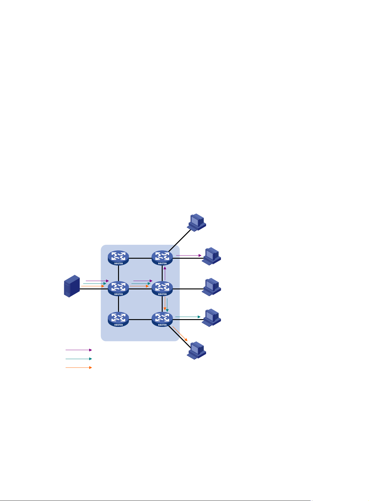
Multicast overview
As a technique that coexists with unicast and broadcast, the multicast technique effectively
addresses the issue of point-to-multipoint data transmission. By enabling high-efficiency
point-to-multipoint data transmission over a network, multicast greatly saves network bandwidth and
reduces network load.
Using multicast technology, a network operator can easily provide bandwidth-critical and time-critical
information services. These services include live webcasting, Web TV, distance learning,
telemedicine, Web radio, and real-time video conferencing.
Unless otherwise stated, the term "multicast" in this document refers to IP multicast.
Information transmission techniques
The information transmission techniques include unicast, broadcast, and multicast.
Unicast
In unicast transmission, the information source must send a separate copy of information to each
host that needs the information.
Figure 1 Unicast transmission
Host A
Receiver
Host B
Source
Host C
Receiver
Host D
IP network
Packets for Host B
Packets for Host D
Packets for Host E
Receiver
Host E
In Figure 1, assume that Host B, Host D and Host E need the information. A separate transmission
channel must be established from the information source to each of these hosts.
In unicast transmission, the traffic transmitted over the network is proportional to the number of hosts
that need the information. If a large number of hosts need the information, the information source
must send a separate copy of the same information to each of these hosts. Sending many copies
can place a tremendous pressure on the information source and the network bandwidth.
Unicast is not suitable for batch transmission of information.
1
Page 14
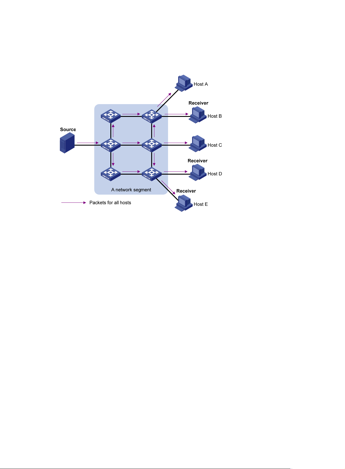
Broadcast
In broadcast transmission, the information source sends information to all hosts on the subnet, even
if some hosts do not need the information.
Figure 2 Broadcast transmission
Multicast
In Figure 2, assume that only Host B, Host D, and Host E need the information. If the information is
broadcast to the subnet, Host A and Host C also receive it. In addition to information security issues,
broadcasting to hosts that do not need the information also causes traffic flooding on the same
subnet.
Broadcast is disadvantageous in transmitting data to specific hosts. Moreover, broadcast
transmission is a significant waste of network resources.
Unicast and broadcast techniques cannot provide point-to-multipoint data transmissions with the
minimum network consumption.
Multicast transmission can solve this problem. When some hosts on the network need multicast
information, the information sender, or multicast source, sends only one copy of the information.
Multicast distribution trees are built through multicast routing protocols, and the packets are
replicated only on nodes where the trees branch.
2
Page 15
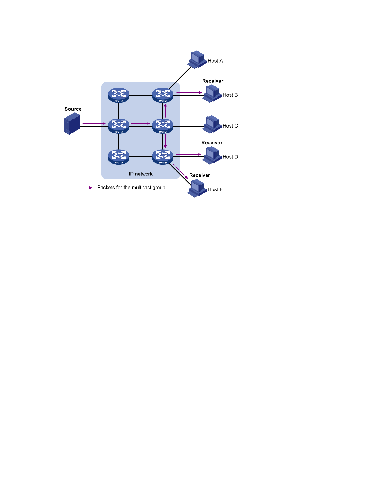
Figure 3 Multicast transmission
As shown in Figure 3, the multicast source sends only one copy of the information to a multicast
group. Host B, Host D and Host E, which are receivers of the information, must join the multicast
group. The routers on the network duplicate and forward the information based on the distribution of
the group members. Finally, the information is correctly delivered to Host B, Host D, and Host E.
To summarize, multicast has the following advantages:
• Advantages over unicast—Multicast traffic is replicated and distributed until it flows to the
farthest-possible node from the source. The increase of receiver hosts will not remarkably
increase the load of the source or the usage of network resources
• Advantages over broadcast—Multicast data is sent only to the receivers that need it. This
reasonably uses network bandwidth and enhances network security. In addition, multicast data
is not confined to the same subnet.
Multicast features
Multicast transmission has the following features:
• A multicast group is a multicast receiver set identified by an IP multicast address. Hosts join a
multicast group to become members of the multicast group before they can receive the
multicast data addressed to that multicast group. Typically, a multicast source does not need to
join a multicast group.
• An information sender is called a "multicast source." A multicast source can send data to
multiple multicast groups at the same time. Multiple multicast sources can send data to the
same multicast group at the same time.
• All hosts that have joined a multicast group become members of the multicast group. The group
memberships are dynamic. Hosts can join or leave multicast groups at any time. Multicast
groups are not subject to geographic restrictions.
• Routers or Layer 3 switches that support Layer 3 multicast are called "multicast routers" or
"Layer 3 multicast devices." In addition to providing the multicast routing function, a multicast
router can also manage multicast group memberships on stub subnets with attached group
members. A multicast router itself can be a multicast group member.
For a better understanding of the multicast concept, you can compare multicast transmission to the
transmission of TV programs as shown in Table 1.
3
Page 16

Table 1 Comparing TV program transmission and multicast transmission
TV transmission Multicast transmission
A TV station transmits a TV program through a
channel.
A user tunes the TV set to the channel. A receiver joins the multicast group.
The user starts to watch the TV program
transmitted by the TV station through the
channel.
The user turns off the TV set or tunes to another
channel.
Common notations in multicast
The following notations are commonly used in multicast transmission:
• (*, G)—Rendezvous point tree (RPT), or a multicast packet that any multicast source sends to
multicast group G. Here, the asterisk represents any multicast source, and "G" represents a
specific multicast group.
• (S, G)—Shortest path tree (SPT), or a multicast packet that multicast source S sends to
multicast group G. Here, "S" represents a specific multicast source, and "G" represents a
specific multicast group.
For more information about the concepts RPT and SPT, see "Configuring PIM" and "Configuring
IPv6 PIM."
A multicast source sends multicast data to a multicast
group.
The receiver starts to receive the multicast data that the
source is sending to the multicast group.
The receiver leaves the multicast group or joins another
group.
Multicast advantages and applications
Multicast advantages
Advantages of the multicast technique include the following:
• Enhanced efficiency—Reduces the processor load of information source servers and network
devices.
• Optimal performance—Reduces redundant traffic.
• Distributed application—Enables point-to-multipoint applications at the price of minimum
network resources.
Multicast applications
The scenarios in which the multicast technique can be effectively applied are:
• Multimedia and streaming applications, such as Web TV, Web radio, and real-time video/audio
conferencing
• Communication for training and cooperative operations, such as distance learning and
telemedicine
• Data warehouse and financial applications (stock quotes)
• Any other point-to-multipoint application for data distribution
Multicast models
Based on how the receivers treat the multicast sources, the multicast models include any-source
multicast (ASM), source-filtered multicast (SFM), and source-specific multicast (SSM).
4
Page 17

ASM model
In the ASM model, any sender can send information to a multicast group as a multicast source.
Receivers can join a multicast group (identified by a group address) and obtain multicast information
addressed to that multicast group. In this model, receivers do not know the positions of the multicast
sources in advance. However, they can join or leave the multicast group at any time.
SFM model
The SFM model is derived from the ASM model. To a sender, the two models appear to have the
same multicast membership architecture.
The SFM model functionally extends the ASM model. The upper-layer software examines the source
address of received multicast packets and permits or denies multicast traffic from specific sources.
Therefore, receivers can receive the multicast data from only part of the multicast sources. To a
receiver, not all multicast sources are valid because they are filtered.
SSM model
Users might be interested in the multicast data from only certain multicast sources. The SSM model
provides a transmission service that enables users to specify the multicast sources that they are
interested in at the client side.
In the SSM model, receivers have already determined the locations of the multicast sources. This is
the main difference between the SSM model and the ASM model. In addition, a different multicast
address range than the ASM/SFM model is used in the SSM model. Dedicated multicast forwarding
paths are established between receivers and the specified multicast sources.
Multicast architecture
IP multicast addresses the following issues:
• Where should the multicast source transmit information to? (Multicast addressing.)
• What receivers exist on the network? (Host registration.)
• Where is the multicast source that provides data to the receivers? (Multicast source discovery.)
• How should information be transmitted to the receivers? (Multicast routing.)
IP multicast is an end-to-end service. The multicast architecture involves the following parts:
• Addressing mechanism—A multicast source sends information to a group of receivers
through a multicast address.
• Host registration—Receiver hosts can join and leave multicast groups dynamically. This
mechanism is the basis for management of group memberships.
• Multicast routing—A multicast distribution tree (a forwarding path tree for multicast data on the
network) is constructed for delivering multicast data from a multicast source to receivers.
• Multicast applications—A software system that supports multicast applications, such as video
conferencing, must be installed on multicast sources and receiver hosts. The TCP/IP stack
must support reception and transmission of multicast data.
Multicast addresses
Network-layer multicast addresses (multicast IP addresses) enables communication between
multicast sources and multicast group members. In addition, a technique must be available to map
multicast IP addresses to link-layer multicast MAC addresses.
IP multicast addresses
• IPv4 multicast addresses:
5
Page 18

Internet Assigned Numbers Authority (IANA) assigned the Class D address space (224.0.0.0 to
239.255.255.255) for IPv4 multicast.
Table 2 Class D IP address blocks and description
Address block Description
Reserved permanent group addresses. The IP address 224.0.0.0
is reserved. Other IP addresses can be used by routing protocols
and for topology searching, protocol maintenance, and so
224.0.0.0 to 224.0.0.255
224.0.1.0 to 238.255.255.255
239.0.0.0 to 239.255.255.255
NOTE:
on. Table 3 lists common permanent group addresses. A packet
destined for an address in this block is not forwarded beyond the
local subnet regardless of the Time to Live (TTL) value in the IP
header.
Globally scoped group addresses. This block includes the
following types of designated group addresses:
• 232.0.0.0/8—SSM group addresses.
• 233.0.0.0/8—Glop group addresses.
Administratively scoped multicast addresses. These addresses
are considered locally unique rather than globally unique, and can
be reused in domains administered by different organizations
without causing conflicts. For more information, see RFC 2365.
"Glop" is a mechanism for assigning multicast addresses between different ASs. By filling an AS
number into the middle two bytes of 233.0.0.0, you get 255 multicast addresses for that AS. For
more information, see RFC 2770.
Table 3 Some reserved multicast addresses
Address Description
224.0.0.1 All systems on this subnet, including hosts and routers.
224.0.0.2 All multicast routers on this subnet.
224.0.0.3 Unassigned.
224.0.0.4 DVMRP routers.
224.0.0.5 OSPF routers.
224.0.0.6 OSPF designated routers and backup designated routers.
224.0.0.7 Shared Tree (ST) routers.
224.0.0.8 ST hosts.
224.0.0.9 RIPv2 routers.
224.0.0.11 Mobile agents.
224.0.0.12 DHCP server/relay agent.
224.0.0.13 All Protocol Independent Multicast (PIM) routers.
224.0.0.14 RSVP encapsulation.
224.0.0.15 CBT routers.
224.0.0.16 Designated SBM.
224.0.0.17 All SBMs.
224.0.0.18 Virtual Router Redundancy Protocol (VRRP).
6
Page 19

• IPv6 multicast addresses:
Figure 4 IPv6 multicast format
The following describes the fields of an IPv6 multicast address as shown in Figure 4:
{ 0xFF—The most significant eight bits are 11111111, which indicates that this address is an
IPv6 multicast address.
{ Flags—The Flags field contains four bits as shown in Figure 5 and described in Table 4.
Figure 5 Flags field format
Table 4 Flags field description
Bit Description
0 Reserved, set to 0.
• When set to 0, it indicates that this address is an IPv6
multicast address without an embedded RP address.
R
• When set to 1, it indicates that this address is an IPv6
multicast address with an embedded RP address. (The P
and T bits must also be set to 1.)
• When set to 0, it indicates that this address is an IPv6
multicast address not based on a unicast prefix.
P
• When set to 1, it indicates that this address is an IPv6
multicast address based on a unicast prefix. (The T bit must
also be set to 1.)
• When set to 0, it indicates that this address is an IPv6
T
multicast address permanently-assigned by IANA.
• When set to 1, it indicates that this address is a transient, or
dynamically assigned IPv6 multicast address.
{ Scope—The Scope field contains four bits, which indicate the scope of the IPv6
internetwork for which the multicast traffic is intended. Table 5 d
escribes the values of the
Scope field.
Table 5 Values of the Scope field
Value Meaning
0, F Reserved.
1 Interface-local scope.
2 Link-local scope.
3 Subnet-local scope.
4 Admin-local scope.
5 Site-local scope.
7
Page 20

Value Meaning
6, 7, 9 through D Unassigned.
8 Organization-local scope.
E Global scope.
{ Group ID—The Group ID field contains 112 bits. It uniquely identifies an IPv6 multicast
group in the scope that the Scope field defines.
Ethernet multicast MAC addresses
A multicast MAC address identifies a group of receivers at the data link layer.
• IPv4 multicast MAC addresses:
As defined by IANA, the most significant 24 bits of an IPv4 multicast MAC address are
0x01005E. Bit 25 is 0, and the other 23 bits are the least significant 23 bits of a multicast IPv4
address.
Figure 6 IPv4-to-MAC address mapping
As shown in Figure 6, the most significant four bits of a multicast IPv4 address are 1110, which
indicates that this address is a multicast address. Only 23 bits of the remaining 28 bits are
mapped to a MAC address, so five bits of the multicast IPv4 address are lost. As a result, 32
multicast IPv4 addresses map to the same IPv4 multicast MAC address. Therefore, in Layer 2
multicast forwarding, a switch might receive some multicast data destined for other IPv4
multicast groups. The upper layer must filter such redundant data.
• IPv6 multicast MAC addresses:
As shown in Figure 7, the
most significant 16 bits of an IPv6 multicast MAC address are 0x3333.
The least significant 32 bits are the least significant 32 bits of a multicast IPv6 address.
Figure 7 An example of IPv6-to-MAC address mapping
8
Page 21
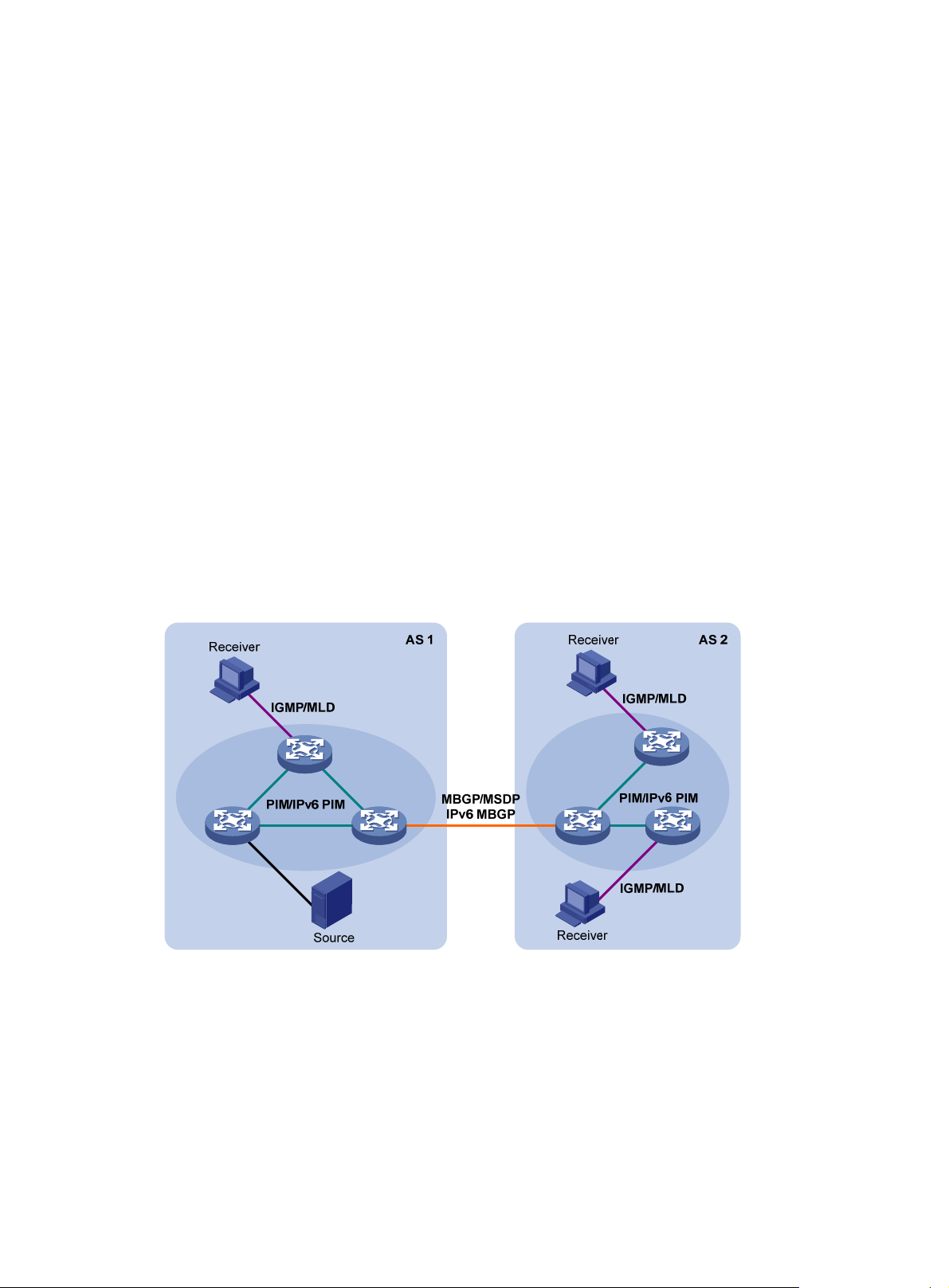
Multicast protocols
Multicast protocols include the following categories:
• Layer 3 and Layer 2 multicast protocols:
{ Layer 3 multicast refers to IP multicast operating at the network layer.
Layer 3 multicast protocols—IGMP, MLD, PIM, IPv6 PIM, MSDP, MBGP, and IPv6
MBGP.
{ Layer 2 multicast refers to IP multicast operating at the data link layer.
Layer 2 multicast protocols—IGMP snooping, MLD snooping, PIM snooping, IPv6 PIM
snooping, multicast VLAN, and IPv6 multicast VLAN.
• IPv4 and IPv6 multicast protocols:
{ For IPv4 networks—IGMP snooping, PIM snooping, multicast VLAN, IGMP, PIM, MSDP,
and MBGP.
{ For IPv6 networks—MLD snooping, IPv6 PIM snooping, IPv6 multicast VLAN, MLD, IPv6
PIM, and IPv6 MBGP.
This section provides only general descriptions about applications and functions of the Layer 2 and
Layer 3 multicast protocols in a network. For more information about these protocols, see the related
chapters.
Layer 3 multicast protocols
Layer 3 multicast protocols include multicast group management protocols and multicast routing
protocols.
Figure 8 Positions of Layer 3 multicast protocols
• Multicast group management protocols:
Typically, the Internet Group Management Protocol (IGMP) or Multicast Listener Discovery
(MLD) protocol is used between hosts and Layer 3 multicast devices that directly connect to the
hosts. These protocols define the mechanism of establishing and maintaining group
memberships between hosts and Layer 3 multicast devices.
• Multicast routing protocols:
A multicast routing protocol runs on Layer 3 multicast devices to establish and maintain
multicast routes and forward multicast packets correctly and efficiently. Multicast routes
constitute loop-free data transmission paths from a data source to multiple receivers, that is, a
multicast distribution tree.
9
Page 22
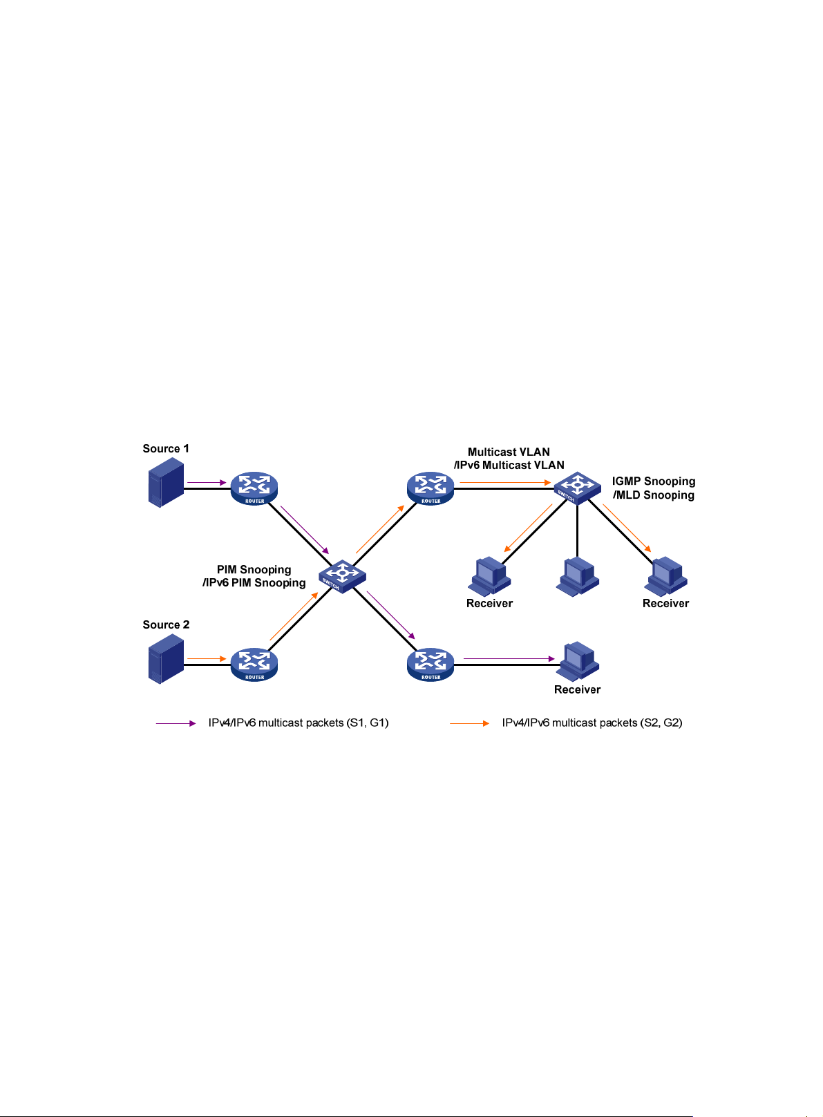
In the ASM model, multicast routes include intra-domain routes and inter-domain routes.
{ An intra-domain multicast routing protocol discovers multicast sources and builds multicast
distribution trees within an AS to deliver multicast data to receivers. Among a variety of
mature intra-domain multicast routing protocols, Protocol Independent Multicast (PIM) is
most widely used. Based on the forwarding mechanism, PIM has dense mode (often
referred to as "PIM-DM") and sparse mode (often referred to as "PIM-SM").
{ An inter-domain multicast routing protocol is used for delivery of multicast information
between two ASs. So far, mature solutions include Multicast Source Discovery Protocol
(MSDP) and Multicast Border Gateway Protocol (MBGP). MSDP propagates multicast
source information among different ASs. MBGP is an extension of the Multiprotocol Border
Gateway Protocol (MP-BGP) for exchanging multicast routing information among different
ASs.
For the SSM model, multicast routes are not divided into intra-domain routes and inter-domain
routes. Because receivers know the position of the multicast source, channels established
through PIM-SM are sufficient for the transport of multicast information.
Layer 2 multicast protocols
Layer 2 multicast protocols include IGMP snooping, MLD snooping, PIM snooping, IPv6 PIM
snooping, multicast VLAN, and IPv6 multicast VLAN.
Figure 9 Positions of Layer 2 multicast protocols
• IGMP snooping and MLD snooping:
IGMP snooping and MLD snooping are multicast constraining mechanisms that run on Layer 2
devices. They manage and control multicast groups by monitoring and analyzing IGMP or MLD
messages exchanged between the hosts and Layer 3 multicast devices. This effectively
controls the flooding of multicast data in a Layer 2 network.
• PIM snooping and IPv6 PIM snooping:
PIM snooping and IPv6 PIM snooping run on Layer 2 devices. They determine which ports are
interested in multicast data by analyzing the received IPv6 PIM messages. Then, they add the
ports to a multicast forwarding entry. In this way, multicast data can be forwarded to only the
ports that are interested in the data.
• Multicast VLAN and IPv6 multicast VLAN:
In the traditional multicast-on-demand mode, when users in different VLANs on a Layer 2
device need multicast information, the upstream Layer 3 device must forward a separate copy
of the multicast data to each VLAN of the Layer 2 device. When the multicast VLAN or IPv6
multicast VLAN feature is enabled on the Layer 2 device, the Layer 3 multicast device sends
10
Page 23

only one copy of multicast to the multicast VLAN or IPv6 multicast VLAN on the Layer 2 device.
This approach avoids wasting network bandwidth and placing an extra burden on the Layer 3
device.
Multicast packet forwarding mechanism
In a multicast model, receiver hosts of a multicast group are usually located at different positions of
the network. They are identified by the same multicast group address. To deliver multicast packets to
these receivers, a multicast source encapsulates the multicast data in an IP packet with the multicast
group address as the destination address. Multicast routers on the forwarding paths usually need to
forward multicast packets that an incoming interface receives through multiple outgoing interfaces.
Compared with a unicast model, a multicast model is more complex in the following aspects:
• To ensure multicast packet transmission in the network, different routing tables are used to
guide multicast forwarding. These routing tables include unicast routing tables and multicast
routing tables (for example, the MBGP routing table) specially provided for multicast.
• To process the same multicast information from different peers received on different interfaces,
the multicast device performs a reverse path forwarding (RPF) check on each multicast packet.
The result of the RPF check determines whether the packet is forwarded or discarded. The RPF
check mechanism is the basis for most multicast routing protocols to implement multicast
forwarding.
For more information about the RPF mechanism, see "Configuring multicast routing and forwarding"
and "Configuring IPv6 multicast routing and forwarding."
Multicast support for VPNs
Multicast support for VPNs refers to multicast applied in virtual private networks (VPNs).
Introduction to VPN instances
VPNs must be isolated from one another and from the public network. As shown in Figure 10, VPN A
and VPN B separately access the public network through PE devices.
11
Page 24
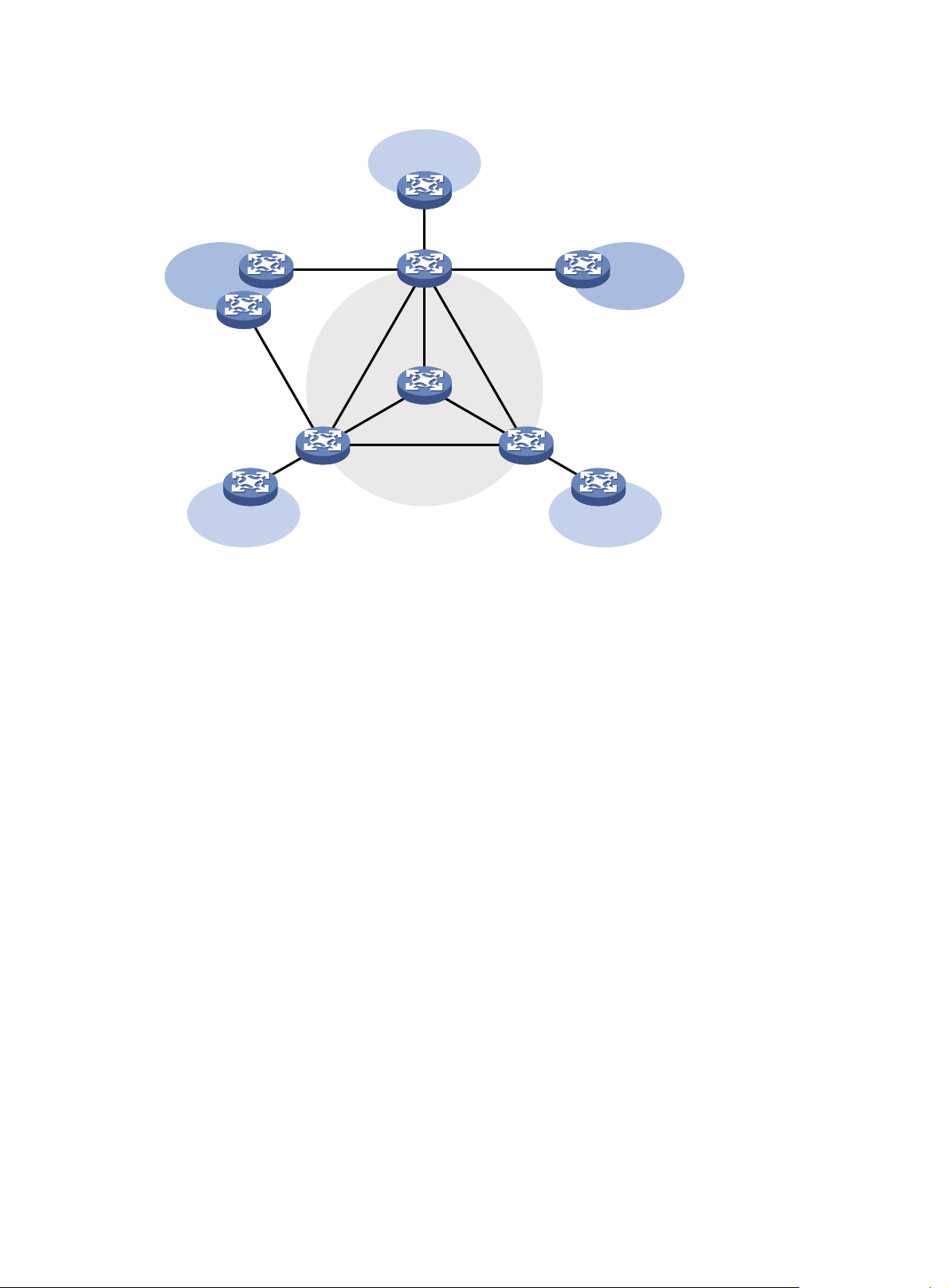
Figure 10 VPN networking diagram
VPN A
CE a2
CE b3
VPN BVPN B
CE a3
PE 3
VPN A
CE b1
CE a1
VPN A
CE b2
PE 1
PE 2
P
Public network
• The provider (P) device belongs to the public network. The customer edge (CE) devices belong
to their respective VPNs. Each CE device serves its own VPN and maintains only one set of
forwarding mechanisms.
• The provider edge (PE) devices connect to the public network and the VPNs. Each PE device
must strictly distinguish the information for different networks, and maintain a separate
forwarding mechanism for each network. On a PE device, a set of software and hardware that
serve the same network forms an instance. Multiple instances can exist on the same PE device,
and an instance can reside on different PE devices. On a PE device, the instance for the public
network is called the public network instance, and those for VPNs are called VPN instances.
Multicast application in VPNs
A PE device that supports multicast for VPNs does the following operations:
• Maintains an independent set of multicast forwarding mechanisms for each VPN, including the
multicast protocols, PIM neighbor information, and multicast routing table. In a VPN, the device
forwards multicast data based on the forwarding table or routing table for that VPN.
• Implements the isolation between different VPNs.
• Implements information exchange and data conversion between the public network and VPN
instances.
Multicast VPN implements multicast on MPLS L3VPN networks. As shown in Figure 10, when a
multicast source in VPN A sends a multicast stream to a multicast group, only the receivers that
belong to both the multicast group and VPN A can receive the multicast stream. The multicast data is
multicast both in VPN A and on the public network.
12
Page 25
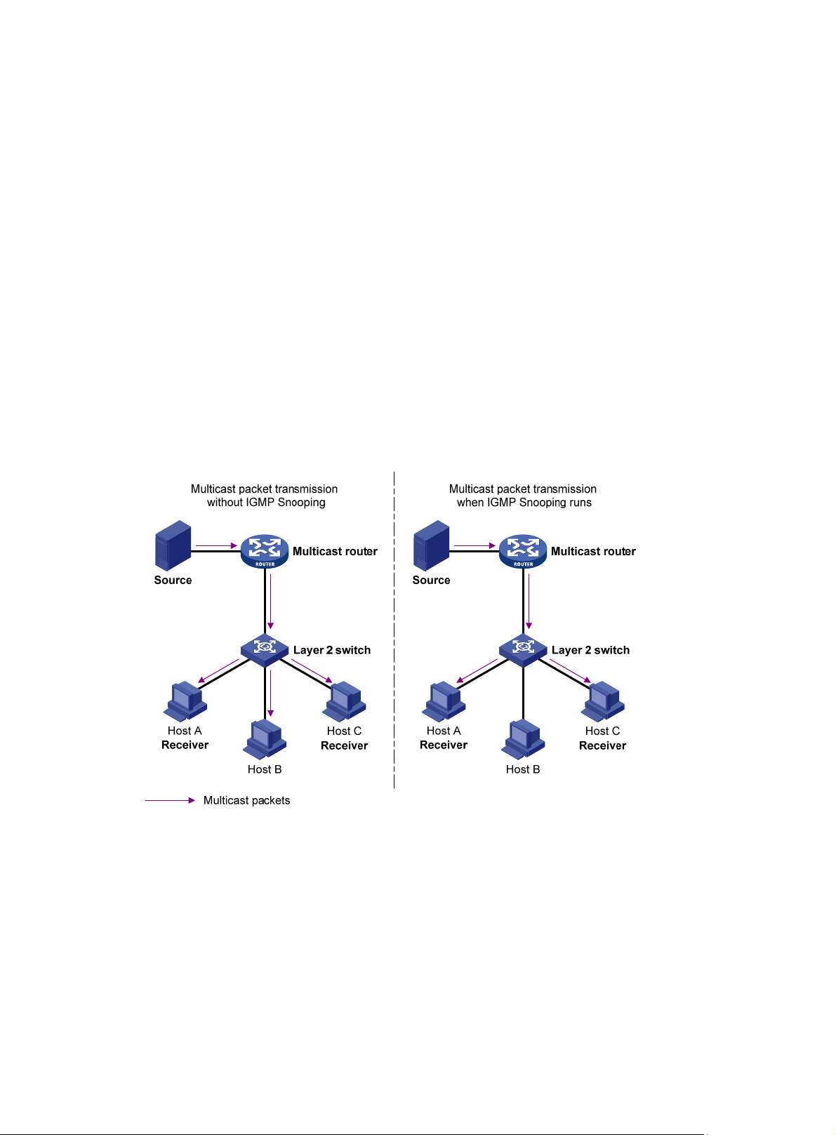
Configuring IGMP snooping
This chapter describes IGMP snooping, how to configure IGMP snooping, configuration examples,
troubleshooting methods, and an appendix about processing multicast protocol messages.
Overview
IGMP snooping is a multicast constraining mechanism that runs on Layer 2 devices to manage and
control multicast groups.
By analyzing received IGMP messages, an IGMP snooping-enabled Layer 2 device establishes
mappings between ports and multicast MAC addresses, and forwards multicast data based on these
mappings.
As shown in Figure 11, without IGMP
to all devices at Layer 2. With IGMP snooping enabled, the Layer 2 switch forwards multicast
packets destined for known multicast groups are multicast to only the receivers that require the
multicast data at Layer 2. This feature improves bandwidth efficiency, enhances multicast security,
and helps per-host accounting for multicast users.
Figure 11 Before and after IGMP snooping is enabled on the Layer 2 device
snooping enabled, the Layer 2 switch floods multicast packets
IGMP snooping basic concepts
This section describes the basic concepts involved in IGMP snooping.
IGMP snooping related ports
As shown in Figure 12, Router A connects to the multicast source, IGMP snooping runs on Switch A
and Switch B, and Host A and Host C are receiver hosts as members of a multicast group.
13
Page 26
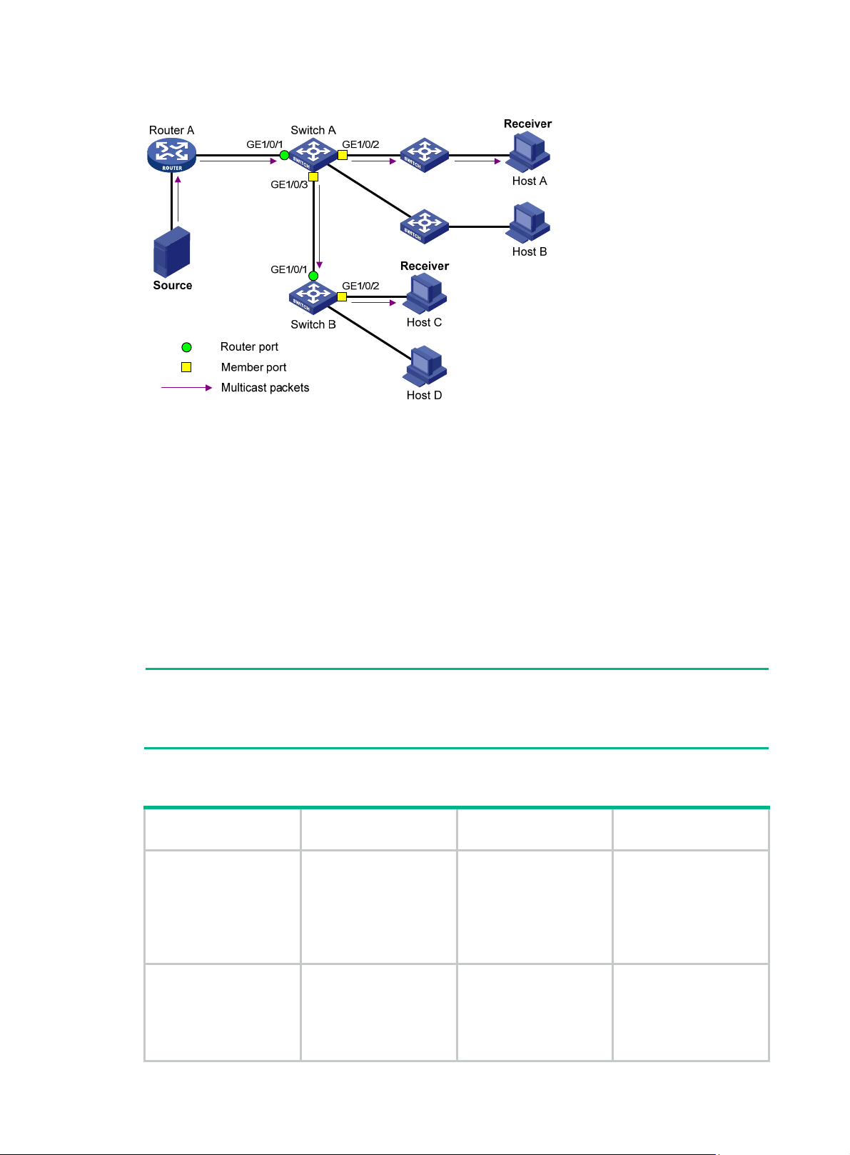
Figure 12 IGMP snooping related ports
The following describes the ports involved in IGMP snooping:
• Router port—Layer 3 multicast device-side port. Layer 3 multicast devices include designated
routers (DRs) and IGMP queriers. In Figure 12, Gig
abitEthernet 1/0/1 of Switch A and
GigabitEthernet 1/0/1 of Switch B are router ports. The switch registers all its router ports in its
router port list.
Do not confuse the "router port" in IGMP snooping with the "routed interface" commonly known
as the "Layer 3 interface." The router port in IGMP snooping is the Layer 2 interface.
• Member port—Multicast receiver-side port. In Figure 12, GigabitEthern
et 1/0/2 and
GigabitEthernet 1/0/3 of Switch A and GigabitEthernet 1/0/2 of Switch B are member ports. The
switch registers all its member ports in its IGMP snooping forwarding table.
Unless otherwise specified, router ports and member ports in this document include both static and
dynamic router ports and member ports.
NOTE:
An IGMP snooping-enabled switch deems that all its ports that receive IGMP general queries with
the source IP address other than 0.0.0.0 or that receive PIM hello messages are dynamic router
ports. For more information about PIM hello messages, see "Configuring PIM."
Aging timers for dynamic ports in IGMP snooping and related messages and actions
Timer Description
When a port receives an
expected message, the
Dynamic router port
aging timer
Dynamic member port
aging timer
switch starts an aging
timer for the port. When
the timer expires, the
dynamic router port ages
out.
When a port dynamically
joins a multicast group,
the switch starts an
aging timer for the port.
When the timer expires,
the dynamic member
Expected message
before expiration
IGMP general query of
which the source
address is not 0.0.0.0 or
PIM hello.
IGMP membership
report.
Action after
expiration
The switch removes this
port from its router port
list.
The switch removes this
port from the IGMP
snooping forwarding
table.
14
Page 27

Timer Description
port ages out.
NOTE:
In IGMP snooping, only dynamic ports age out. Static ports never age out.
How IGMP snooping operates
An IGMP snooping-enabled switch performs different actions when it receives different IGMP
messages.
In this section, the involved ports are dynamic ports. For information about how to configure and
remove static ports, see "Configuring static ports."
When receiving a general query
To check for the existence of multicast group members, the IGMP querier periodically sends IGMP
general queries to all hosts and routers on the local subnet. All these hosts and routers are
indentified by the multicast address 224.0.0.1.
After receiving an IGMP general query, the switch forwards it to all ports in the VLAN, except the port
that received the query. The switch also performs one of the following actions:
• If the receiving port is a dynamic router port in the router port list, restarts the aging timer for the
port.
• If the receiving port is not in the router port list, adds it into the router port list as a dynamic
router port. It also starts an aging timer for the port.
Expected message
before expiration
Action after
expiration
When receiving a membership report
A host sends an IGMP report to the IGMP querier for the following purposes:
• If the host has been a member of a multicast group, responds to the query with an IGMP report.
• Applies for joining a multicast group.
After receiving an IGMP report, the switch forwards it through all router ports in the VLAN. it also
resolves the address of the reported multicast group, and looks up the multicast forwarding table for
a matching entry:
• If no match is found, the Layer 2 device creates a forwarding entry for the group with the
receiving port as an outing interface. It also marks the receiving port as a dynamic member port
and starts an aging timer for the port.
• If a match is found but the receiving port is not in the forwarding entry, the Layer 2 device adds
the port as an outgoing interface to the entry. It also marks the port as a dynamic member port
and starts an aging timer for the port.
• If a match is found and the receiving port is in the forwarding entry, the Layer 2 device restarts
the aging timer for the port.
A switch does not forward an IGMP report through a non-router port because of IGMP report
suppression mechanism. Assuming the switch forwards a report message through a member port,
all attached member receivers will receive the report and suppress their own reports. This makes the
switch unable to know whether the reported multicast group still has active members attached to that
port. For more information about the IGMP report suppression mechanism, see "Configuring IGMP."
When receiving a leave message
An IGMPv1 host does not send any leave messages when it leaves a multicast group. Therefore, the
Layer 2 device cannot immediately update the status of the port that connects to the receiver host. In
this case, when the aging timer for the multicast group on the port expires, the Layer 2 device
15
Page 28

removes the port from the associated forwarding entry. For a static member port, this mechanism
does not take effect.
When an IGMPv2 or IGMPv3 host leaves a multicast group, the host sends an IGMP leave message
to the multicast router.
When the switch receives an IGMP leave message on a dynamic member port, the switch first
examines whether a forwarding entry matches the group address in the message:.
• If no match is found. the switch directly discards the IGMP leave message.
• If a match is found but the receiving port is not in the forwarding entry, the switch directly
discards the IGMP leave message.
• If a match is found and the receiving port is in the forwarding entry, the switch forwards the
leave message to all router ports in the VLAN. Without knowing whether any other attached
hosts are still listening to that group, the switch does not immediately remove the port from the
forwarding entry. Instead, it restarts the aging timer for the port.
After receiving the IGMP leave message, the IGMP querier resolves the multicast group address in
the message. Then, it sends an IGMP group-specific query to the multicast group through the port
that received the leave message.
After receiving the IGMP group-specific query, the switch forwards the query through all its router
ports in the VLAN and all member ports of the multicast group. Then, the switch waits for the
responding IGMP reports from the directly connected hosts to check for the existence of members
for the multicast group. For the port that receives the leave message (assuming that it is a dynamic
member port), the Layer 2 device also performs one of the following actions:
• If the port receives an IGMP report before the aging timer expires, the switch restarts the aging
timer for the port.
• If the port does not receive an IGMP report when the aging timer expires, the switch removes
the port from the forwarding entry for the multicast group.
IGMP snooping proxying
You can configure the IGMP snooping proxying function on an edge device to reduce the number of
IGMP reports and leave messages sent to its upstream device. The device configured with IGMP
snooping proxying is called an IGMP snooping proxy. It is a host from the perspective of its upstream
device.
NOTE:
Even though an IGMP snooping proxy is a host from the perspective of its upstream device, the
IGMP membership report suppression mechanism for hosts does not affect it. For more information
about the IGMP report suppression mechanism for hosts, see "Configuring IGMP."
16
Page 29
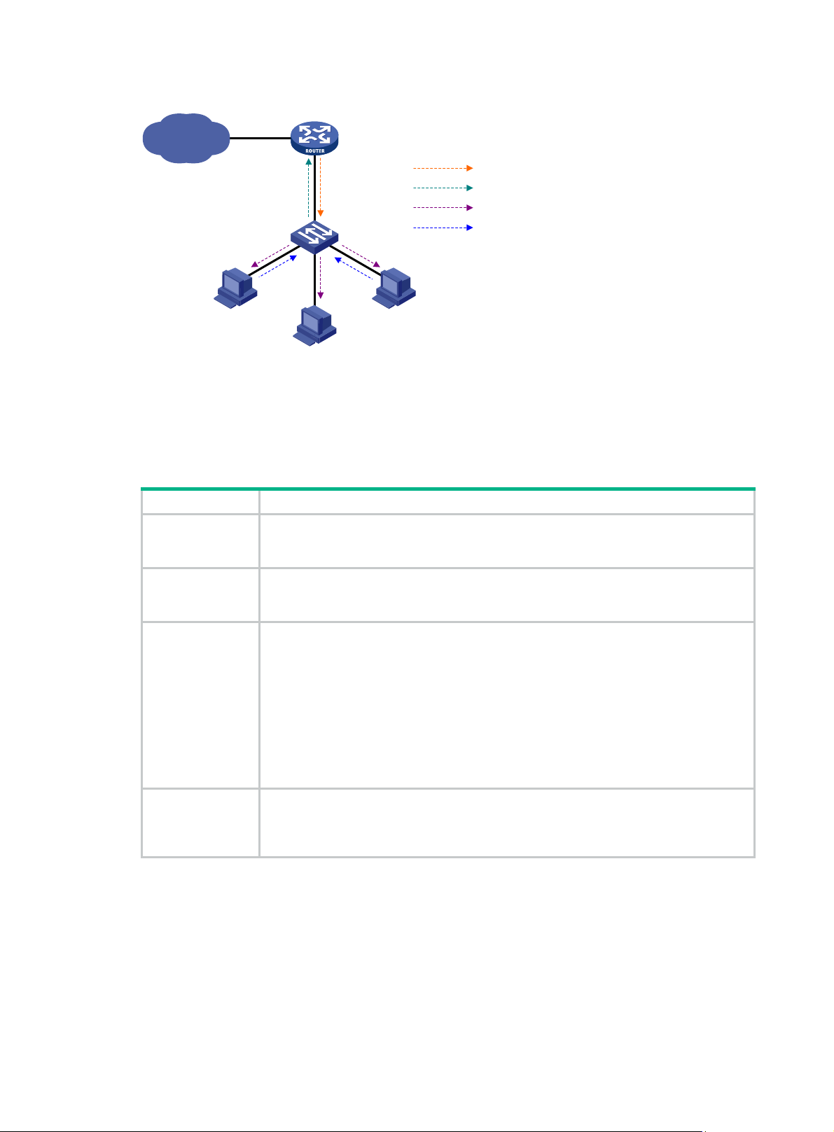
Figure 13 Network diagram
IP network
Proxy & Querier
Switch A
Host A
Receiver
Host B
IGMP Querier
Router A
Query from Router A
Report from Switch A
Query from Switch A
Report from Host
Host C
Receiver
As shown in Figure 13, Switch A works as an IGMP snooping proxy. As a host from the perspective of
the querier Router A, Switch A represents its attached hosts to send membership reports and leave
messages to Router A. Tab le 6 lists th
e IGMP messages and their processing on an IGMP snooping
proxy.
Table 6 IGMP message processing on an IGMP snooping proxy
IGMP message Actions
When receiving an IGMP general query, the proxy forwards it to all ports except the port
General query
that receive the query. In addition, the proxy generates a report according to the group
membership that it maintains and sends the report out of all router ports.
Group-specific
query
Report
Leave
In response to the IGMP group-specific query for a certain multicast group, the proxy
sends the report to the group out of all router ports if the forwarding entry for the group
still contains a member port.
After receiving a report for a multicast group, the proxy looks up the multicast
forwarding table for a matching forwarding entry.
• If a match is found and the matching entry contains the receiving port as a dynamic
member port, the proxy restarts the aging timer for the port.
• If a match is found but the matching entry does not contain the receiving port, the
proxy adds the port to the forwarding entry. It also marks the port as a dynamic
member port and starts an aging timer for the port.
• If no match is found, the proxy creates a forwarding entry for the multicast group
with the receiving port as an outgoing interface. It also marks the port as a dynamic
member port and starts an aging timer for the port.
In response to an IGMP leave message for a multicast group, the proxy sends a
group-specific query out of the receiving port. After making sure that no member port is
contained in the forwarding entry for the multicast group, the proxy sends a leave
message to the group out of all router ports.
17
Page 30

Protocols and standards
RFC 4541, Considerations for Internet Group Management Protocol (IGMP) and Multicast Listener
Discovery (MLD) Snooping Switches
IGMP snooping configuration task list
For the configuration tasks in this section, the following rules apply:
• The configurations made in IGMP-snooping view are effective for all VLANs. The configuration
made in VLAN view are effective for only the current VLAN. For a given VLAN, a configuration
made in IGMP-snooping view is effective only if you do not make the same configuration in
VLAN view.
• The configurations made in IGMP-snooping view are effective for all ports. The configurations
made in Layer 2 Ethernet interface view or Layer 2 aggregate interface view are effective for
only the current port. The configurations made in port group view are effective for all ports in
only the current port group. For a given port, a configuration made in IGMP-snooping view is
effective only if you do not make the same configuration in Layer 2 Ethernet interface view,
Layer 2 aggregate interface view, or port group view.
• The IGMP snooping configurations made on Layer 2 aggregate interfaces do not interfere with
the configurations made on member ports. In addition, the configurations made on Layer 2
aggregate interfaces do not take part in aggregation calculations. The configurations made on a
member port of the aggregate group will take effect after the port leaves the aggregate group.
Task Remarks
uired.
Optional.
Optional.
Optional.
Configuring basic IGMP
snooping functions
Configuring IGMP snooping
port functions
Configuring an IGMP snooping
querier
Configuring IGMP snooping
proxying
Enabling IGMP snooping Req
Specifying the version of IGMP snooping Optional.
Setting the maximum number of IGMP snooping
forwarding entries
Configuring static multicast MAC address entries Optional.
Setting aging timers for dynamic ports Optional.
Configuring static ports Optional.
Configuring a port as a simulated member host Optional.
Enabling IGMP snooping fast-leave processing Optional.
Disabling a port from becoming a dynamic router port Optional.
Enabling IGMP snooping querier Optional.
Configuring parameters for IGMP queries and
responses
Configuring the source IP addresses for IGMP queries Optional.
Enabling IGMP snooping proxying Optional.
Configuring the source IP addresses for the IGMP
messages sent by the proxy
18
Page 31

Task Remarks
Configuring a multicast group filter Optional.
Configuring multicast source port filtering Optional.
Enabling dropping unknown multicast data Optional.
Enabling IGMP report suppression Optional.
Configuring IGMP snooping
policies
Setting the maximum number of multicast groups that a
port can join
Enabling multicast group replacement Optional.
Setting the 802.1p precedence for IGMP messages Optional.
Configuring a multicast user control policy Optional.
Enabling the IGMP snooping host tracking function Optional.
Setting the DSCP value for IGMP messages Optional.
Optional.
Configuring basic IGMP snooping functions
This section describes how to configure basic IGMP snooping functions.
Configuration prerequisites
Before you configure basic IGMP snooping functions, complete the following tasks:
• Configure the corresponding VLANs.
• Determine the version of IGMP snooping.
Enabling IGMP snooping
This section describes how to enable IGMP snooping.
Configuration guidelines
• You must enable IGMP snooping globally before you enable it for a VLAN.
• If you enable IGMP snooping for a VLAN, do not enable IGMP or PIM on the corresponding
VLAN interface. If you enable IGMP or PIM on a VLAN interface, do not enable IGMP snooping
for the VLAN.
• IGMP snooping for a VLAN works on only the ports in this VLAN.
Configuration procedure
To enable IGMP snooping:
Step Command Remarks
1. Enter system view.
2. Enable IGMP snooping globally
and enter IGMP-snooping view.
3. Return to system view.
4. Enter VLAN view.
system-view
igmp-snooping
quit
vlan
vlan-id
19
N/A
Disabled by default.
N/A
N/A
Page 32

Step Command Remarks
5. Enable IGMP snooping in the
VLAN.
igmp-snooping enable
Specifying the version of IGMP snooping
Different versions of IGMP snooping can process different versions of IGMP messages:
• IGMPv2 snooping can process IGMPv1 and IGMPv2 messages, but flood IGMPv3 messages
in the VLAN instead of processing them.
• IGMPv3 snooping can process IGMPv1, IGMPv2 and IGMPv3 messages.
If you change IGMPv3 snooping to IGMPv2 snooping, the system does the following:
• Clears all IGMP snooping forwarding entries that are dynamically added.
• Keeps static IGMPv3 snooping forwarding entries (*, G).
• Clears static IGMPv3 snooping forwarding entries (S, G), which will be restored when IGMP
snooping is switched back to IGMPv3 snooping.
For more information about static joins, see "Configuring static ports."
o specify the version of IGMP snooping:
T
Disabled by default.
Step Command Remarks
1. Enter system view.
2. Enter VLAN view.
3. Specify the version of IGMP
snooping.
system-view
vlan vlan-id
igmp-snooping version
version-number
N/A
N/A
IGMPv2 snooping by default.
Setting the maximum number of IGMP snooping forwarding entries
You can modify the maximum number of entries in the IGMP snooping forwarding table. When the
number of existing forwarding entries reaches the upper limit, the device does not create new entries
until some entries time out or are removed. In this case, Hewlett Packard Enterprise recommends
that you manually remove some entries, because the device does not automatically remove any
existing entries.
To set the maximum number of IGMP snooping forwarding entries:
Step Command Remarks
1. Enter system view.
2. Enter IGMP-snooping view.
3. Set the maximum number of
IGMP snooping forwarding
entries.
system-view
igmp-snooping
entry-limit
limit
N/A
N/A
By default, the upper limit is 4000
for the HPE 5800 switches, and
2000 for the HPE 5820X switches.
NOTE:
IGMP snooping forwarding entries created for multicast VLAN are not limited by this command. You
can use the multicast-vlan entry-limit to limit the number of entries in the IGMP snooping
forwarding table of a multicast VLAN. For more information, see "Configuring multicast VLANs."
20
Page 33

Configuring static multicast MAC address entries
In Layer-2 multicast, a Layer 2 multicast protocol (such as IGMP snooping) can dynamically add
multicast MAC address entries. Or, you can manually configure multicast MAC address entries.
Configuration guidelines
• You can configure a static multicast MAC address entry for any legal multicast MAC address. A
multicast MAC address is a MAC address in which the least significant bit of the the most
significant octet is 1.
• When you configure a static multicast MAC address entry in system view, the configuration is
effective on the specified interfaces. When you configure a static multicast MAC address entry
in interface view or port group view, the configuration is effective only on the current interface or
all interfaces in the current port group.
Configuration procedure
To configure a static multicast MAC address entry in system view:
Step Command Remarks
1. Enter system view.
system-view
N/A
2. Configure a static multicast
MAC address entry.
To configure a static multicast MAC address entry in interface view:
mac-address multicast
mac-address
interface-list
interface
vlan
vlan-id
No static multicast MAC address
entries exist by default.
Step Command Remarks
1. Enter system view.
2. Enter Ethernet
interface/Layer 2 aggregate
interface view or port group
view.
3. Configure a static multicast
MAC address entry.
system-view
• Enter Ethernet
interface/Layer 2 aggregate
interface view:
interface interface-type
interface-number
• Enter port group view:
port-group manual
port-group-name
mac-address multicast
mac-address
vlan
vlan-id
N/A
In Ethernet interface view or Layer
2 aggregate interface view, the
configuration is effective on only
the current interface. In port group
view, the configuration is effective
on all ports in the port group.
No static multicast MAC address
entries exist by default.
Configuring IGMP snooping port functions
This section describes how to configure IGMP snooping port functions.
Configuration prerequisites
Before you configure IGMP snooping port functions, complete the following tasks:
• Enable IGMP snooping in the VLAN.
• Configure the corresponding port groups.
• Determine the aging timer for dynamic router ports.
• Determine the aging timer for dynamic member ports.
21
Page 34

• Determine the multicast group and multicast source addresses.
Setting aging timers for dynamic ports
If the memberships of multicast groups change frequently, you can set a relatively small value for the
aging timer of the dynamic member ports. If the memberships of multicast groups change rarely, you
can set a relatively large value.
Setting aging timers for dynamic ports globally
Step Command Remarks
1. Enter system view.
2. Enter IGMP-snooping view.
3. Set the aging timer for the
dynamic router ports.
4. Set the aging timer for the
dynamic member ports.
Setting aging timers for the dynamic ports in a VLAN
system-view
igmp-snooping
router-aging-time
host-aging-time
interval 105 seconds by default.
interval 260 seconds by default.
N/A
N/A
Step Command Remarks
1. Enter system view.
2. Enter VLAN view
3. Set the aging timer for the
dynamic router ports.
4. Set the aging timer for the
dynamic member ports.
Configuring static ports
You can configure a port as a static port for the following purposes:
• To make all the hosts attached to the port receive multicast data addressed to a multicast group,
configure the port as a static member port for the multicast group.
• To make the Layer 2 device attached to the port forward all received multicast traffic on the port,
configure the port as a static router port.
Configuration guidelines
• A static member port does not respond to queries from the IGMP querier. When you configure a
port as a static member port or cancel this configuration on the port, the port does not
unsolicitedly send any IGMP report or an IGMP leave message.
• Static member ports and static router ports never age out. To remove such a port, use the
corresponding undo command.
system-view
vlan
igmp-snooping
router-aging-time
igmp-snooping host-aging-time
interval
vlan-id
interval
N/A
N/A
105 seconds by default.
260 seconds by default.
Configuration procedure
To configure static ports:
Step Command Remarks
1. Enter system view.
system-view
22
N/A
Page 35

Step Command Remarks
• Enter Layer 2 Ethernet
interface view or Layer 2
2. Enter Layer 2 Ethernet
interface view or Layer 2
aggregate interface view, or
enter port group view.
aggregate interface view:
interface interface-type
interface-number
• Enter port group view:
port-group manual
port-group-name
Use either command.
3. Configure the port as a static
member port.
4. Configure the port as a static
router port.
igmp-snooping static-group
group-address [
source-address ]
igmp-snooping
static-router-port vlan
source-ip
vlan
vlan-id
vlan-id
No static member ports exist by
default.
No static router ports exist by
default.
Configuring a port as a simulated member host
Generally, a host that runs IGMP can respond to IGMP queries. If a host fails to respond, the
multicast router might deem that no member of this multicast group exists on the subnet, and
removes the corresponding forwarding path.
To avoid this situation, you can configure the port as a simulated member host for a multicast group.
When the simulated member host receives an IGMP query, it gives a response. Therefore, the switch
can continue receiving multicast data.
A simulated host is equivalent to a real, independent host in the following ways:
• When a port is configured as a simulated member host, the switch can send an unsolicited
IGMP report through the port. It can also respond to IGMP general queries with IGMP reports
through the port.
• When you disable the simulated joining function on the port, the switch sends an IGMP leave
message through the port.
To configure a port as a simulated member host:
Step Command Remarks
1. Enter system view.
2. Enter Layer 2 Ethernet
interface view or Layer 2
aggregate interface view, or
enter port group view.
3. Configure the port as a
simulated member host.
NOTE:
system-view
• Enter Layer 2 Ethernet interface view
or Layer 2 aggregate interface view:
interface interface-type
interface-number
• Enter port group view:
port-group manual
port-group-name
igmp-snooping host-join
source-ip
[
source-address ]
group-address
vlan
vlan-id
N/A
Use either command.
Not configured by default.
Unlike a static member port, a port that you configure as a simulated member host ages out like a
dynamic member port.
23
Page 36

Enabling IGMP snooping fast-leave processing
IGMP snooping fast-leave processing feature enables the switch to process IGMP leave messages
quickly. With IGMP snooping feature enabled, when the switch receives an IGMP leave message on
a port, it immediately removes that port from the forwarding entry for the multicast group specified in
the message. Then, when the switch receives IGMP group-specific queries for that multicast group,
it does not forward them to that port.
On a port that has only one host attached, you can enable IGMP snooping fast-leave processing to
save bandwidth and resources. However, on a port that has multiple hosts attached, do not enable
IGMP snooping fast-leave processing if dropping unknown multicast data is enabled. Otherwise, if a
host on the port leaves a multicast group, the other hosts attached to the port in the same multicast
group cannot receive the multicast data for the group.
Enabling IGMP snooping fast-leave processing globally
Step Command Remarks
1. Enter system view.
system-view
N/A
2. Enter IGMP-snooping view.
3. Enable IGMP snooping
fast-leave processing.
igmp-snooping
fast-leave [ vlan
vlan-list
N/A
]
Disabled by default.
Enabling IGMP snooping fast-leave processing on a port
Step Command Remarks
1. Enter system view.
2. Enter Layer 2 Ethernet
interface view or Layer 2
aggregate interface view, or
enter port group view.
3. Enable IGMP snooping
fast-leave processing on the
port.
system-view
• Enter Layer 2 Ethernet interface view
or Layer 2 aggregate interface view:
interface interface-type
interface-number
• Enter port group view:
port-group manual
port-group-name
igmp-snooping fast-leave [ vlan
vlan-list
]
N/A
Use either command.
Disabled by default.
Disabling a port from becoming a dynamic router port
The following problems might exist in a multicast access network:
• After receiving an IGMP general query or a PIM hello message from a connected host, a router
port becomes a dynamic router port. Before its timer expires, this dynamic router port receives
all multicast packets within the VLAN where the port belongs, and forwards them to the host,
affecting normal multicast reception of the host.
• In addition, the IGMP general query or PIM hello message that the host sends affects the
multicast routing protocol state on Layer 3 devices, such as the IGMP querier or DR election.
This might further cause network interruption.
To solve these problems, after the router port receives an IGMP general query or a PIM hello
message, disable the port from becoming a dynamic router port. This enhances network security and
the control over multicast users.
24
Page 37

To disable a port from becoming a dynamic router port:
Step Command Remarks
1. Enter system view.
2. Enter Layer 2 Ethernet
interface view or Layer 2
aggregate interface view, or
enter port group view.
3. Disable the port from
becoming a dynamic router
port.
NOTE:
system-view
• Enter Layer 2 Ethernet
interface view or Layer 2
aggregate interface view:
interface interface-type
interface-number
• Enter port group view:
port-group manual
port-group-name
igmp-snooping
router-port-deny [ vlan
vlan-list
N/A
Use either command.
By default, a port can become a
dynamic router port.
]
This configuration does not affect the static router port configuration.
Configuring an IGMP snooping querier
This section describes how to configure an IGMP snooping querier.
Configuration prerequisites
Before you configure an IGMP snooping querier, complete the following tasks:
• Enable IGMP snooping in the VLAN.
• Determine the interval for sending IGMP general queries.
• Determine the IGMP last-member query interval.
• Determine the maximum response delay for IGMP general queries.
• Determine the source address of IGMP general queries.
• Determine the source address of IGMP group-specific queries.
Enabling IGMP snooping querier
In an IP multicast network that runs IGMP, a multicast router or Layer 3 multicast switch regularly
sends IGMP queries. This allows all Layer 3 multicast devices to establish and maintain multicast
forwarding entries for correctly forwarding multicast traffic at the network layer. This router or Layer 3
switch is called the "IGMP querier."
However, a Layer 2 multicast switch does not support IGMP and therefore cannot send general
queries by default. To provide correct multicast data forwarding at the data link layer on a network
without Layer 3 multicast devices, you can configure a Layer 2 switch as the IGMP snooping querier.
In this way, the Layer 2 switch sends IGMP queries and establishes and maintains multicast
forwarding entries.
Do not configure an IGMP snooping querier in a multicast network that runs IGMP. An IGMP
snooping querier does not take part in IGMP querier elections. However, it might affect IGMP querier
elections because it sends IGMP general queries with a low source IP address. For more information
about IGMP querier, see "Configuring IGMP."
o enable the IGMP snooping querier in a VLAN:
T
25
Page 38

Step Command Remarks
1. Enter system view.
2. Enter VLAN view.
3. Enable the IGMP snooping
querier in the VLAN.
system-view
vlan-id
vlan
igmp-snooping querier
N/A
N/A
Disabled by default.
Configuring parameters for IGMP queries and responses
CAUTION:
In the configuration, make sure the IGMP general query interval is larger than the maximum
response delay for IGMP general queries. Otherwise, multicast group members might be deleted by
mistake.
You can modify the IGMP general query interval based on actual condition of the network.
A multicast listening host starts a timer for each multicast group that it has joined when it receives an
IGMP query (general query or group-specific query). This timer is initialized to a random value
ranging from 0 to the maximum response delay advertised in the IGMP query message. When the
timer value decreases to 0, the host sends an IGMP report to the multicast group.
To speed up the response of hosts to IGMP queries and avoid simultaneous timer expirations
causing IGMP report traffic bursts, set a proper value for the maximum response delay:
• The maximum response delay for IGMP general queries is set by the max-response-time
command.
• The maximum response delay for IGMP group-specific queries equals the IGMP last-member
query interval.
Configuring the global parameters for IGMP queries and responses
Step Command Remarks
1. Enter system view.
2. Enter IGMP-snooping view.
3. Set the maximum response
delay for IGMP general
queries.
4. Set the IGMP last-member
query interval.
system-view
igmp-snooping
max-response-time
last-member-query-interval
interval
interval 1 second by default.
Configuring the parameters for IGMP queries and responses in a VLAN
Step Command Remarks
1. Enter system view.
2. Enter VLAN view.
3. Set the interval for sending
IGMP general queries.
4. Set the maximum response
delay for IGMP general
queries.
system-view
vlan
igmp-snooping query-interval
igmp-snooping max-response-time
interval
vlan-id
interval
N/A
N/A
10 seconds by default.
N/A
N/A
60 seconds by default.
10 seconds by default.
5. Set the IGMP last-member
igmp-snooping
26
1 second by default.
Page 39

r
Step Command Remarks
query interval.
last-membe
-query-interval
interval
Configuring the source IP addresses for IGMP queries
IMPORTANT:
Changing the source address for IGMP query messages might affect the IGMP querier election
within the subnet.
After a switch receives an IGMP query whose source IP address is 0.0.0.0 on a port, it does not enlist
that port as a dynamic router port. This might prevent multicast forwarding entries from being
correctly created at the data link layer and eventually cause multicast traffic forwarding to fail. To
avoid this problem, when a Layer 2 switch acts as the IGMP snooping querier, Hewlett Packard
Enterprise recommends you configure a non-all-zero IP address as the source IP address of IGMP
queries.
To configure source IP addresses of IGMP queries:
Step Command Remarks
1. Enter system view.
2. Enter VLAN view.
3. Configure the source IP
address for IGMP general
queries.
4. Configure the source IP
address for IGMP
group-specific queries.
system-view
vlan-id
current-interface
current-interface
}
}
vlan
igmp-snooping general-query source-ip
{ ip-address |
igmp-snooping special-query source-ip
{ ip-address |
N/A
N/A
0.0.0.0 by default.
0.0.0.0 by default.
Configuring IGMP snooping proxying
This section describes how to configure IGMP snooping proxying.
Configuration prerequisites
Before you configure IGMP snooping proxying in a VLAN, complete the following tasks:
• Enable IGMP snooping in the VLAN.
• Determine the source IP address for the IGMP reports sent by the proxy.
• Determine the source IP address for the IGMP leave messages sent by the proxy.
Enabling IGMP snooping proxying
The IGMP snooping proxying function works on a per-VLAN basis. After you enable the function in a
VLAN, the device works as the IGMP snooping proxy for the downstream hosts and upstream router
in the VLAN.
To enable IGMP snooping proxying in a VLAN:
27
Page 40

Step Command Remarks
1. Enter system view.
2. Enter VLAN view.
3. Enable IGMP snooping
proxying in the VLAN.
system-view
vlan-id
vlan
igmp-snooping proxying enable
N/A
N/A
Disabled by default.
Configuring the source IP addresses for the IGMP messages sent by the proxy
You can set source the IP addresses for the IGMP reports and leave messages that the IGMP
snooping proxy sends on behalf of its attached hosts.
To configure the source IP addresses for the IGMP messages sent by the proxy in a VLAN:
Step Command Remarks
1. Enter system view.
2. Enter VLAN view.
3. Configure the source IP
address for the IGMP
reports that the proxy
sends.
4. Configure the source IP
address for the IGMP
leave messages that the
proxy sends.
system-view
vlan-id
current-interface
current-interface
}
}
vlan
igmp-snooping report source-ip
{ ip-address |
igmp-snooping leave source-ip
{ ip-address |
N/A
N/A
The default is 0.0.0.0.
The default is 0.0.0.0.
Configuring IGMP snooping policies
This section describes how to configure IGMP snooping policies.
Configuration prerequisites
Before you configure IGMP snooping policies, complete the following tasks:
• Enable IGMP snooping for the VLAN.
• Determine the ACL rule for multicast group filtering.
• Determine the maximum number of multicast groups that a port can join.
• Determine the 802.1p precedence for IGMP messages.
Configuring a multicast group filter
On an IGMP snooping-enabled switch, you can configure a multicast group filter to limit multicast
programs available to users.
In an application, when a user requests a multicast program, the user's host initiates an IGMP report.
After receiving this report message, the switch resolves the multicast group address in the report and
looks up the ACL. If a match is found to permit the port that received the report to join the multicast
group, the switch creates an IGMP snooping forwarding entry for the multicast group and adds the
port to the forwarding entry. Otherwise, the switch drops this report message, in which case, the
28
Page 41

multicast data for the multicast group is not sent to this port, and the user cannot retrieve the
program.
Configuration guidelines
• When you configure a multicast group filter in a multicast VLAN, be sure to configure the filter in
the sub-VLANs of the multicast VLAN. Otherwise, the configuration does not take effect.
• In IGMPv3, when a host is enabled to join multiple multicast groups, the multicast group filter
cannot correctly filter multicast groups because the host that runs IGMPv3 sends multiple
multicast groups that it wants to join in one membership report.
Configuration procedure
To configure a multicast group filter globally:
Step Command Remarks
1. Enter system view.
2. Enter IGMP-snooping view.
system-view
igmp-snooping
N/A
N/A
3. Configure a multicast group
filter globally.
To configure a multicast group filter on a port:
group-policy
vlan-list
]
acl-number [
vlan
Step Command Remarks
1. Enter system view.
2. Enter Layer 2 Ethernet
interface view or Layer 2
aggregate interface view, or
enter port group view.
3. Configure a multicast group
filter on a port.
system-view
• Enter Layer 2 Ethernet
interface view or Layer 2
aggregate interface view:
interface interface-type
interface-number
• Enter port group view:
port-group manual
port-group-name
igmp-snooping group-policy
acl-number [
vlan
vlan-list
]
Configuring multicast source port filtering
By default, no group filter is
globally configured. That is, a host
can join any valid multicast group.
N/A
Use either command.
By default, no group filter is
configured on the current port.
That is, the hosts on this port can
join any valid multicast group.
When the multicast source port filtering feature is enabled on a port, the port can connect to only
multicast receivers rather than to multicast sources, because the port blocks all multicast data
packets but it permits multicast protocol packets to pass.
If this feature is disabled on a port, the port can connect to both multicast sources and multicast
receivers.
Configuring multicast source port filtering globally
Step Command Remarks
1. Enter system view.
2. Enter IGMP-snooping view.
system-view
igmp-snooping
29
N/A
N/A
Page 42

Step Command Remarks
3. Enable multicast source port
filtering.
source-deny port
Configuring multicast source port filtering on a port
Step Command Remarks
1. Enter system view.
2. Enter Layer 2 Ethernet
interface view or Layer 2
aggregate interface view, or
enter port group view.
3. Enable multicast source port
filtering.
system-view
• Enter Layer 2 Ethernet
interface view or Layer 2
aggregate interface view:
interface interface-type
interface-number
• Enter port group view:
port-group manual
port-group-name
igmp-snooping source-deny
interface-list
Disabled by default.
N/A
Use either command.
Disabled by default.
Enabling dropping unknown multicast data
Unknown multicast data refers to multicast data for which no forwarding entries exist in the IGMP
snooping forwarding table. When the switch receives such multicast traffic, one of the following
occurs:
• When the function of dropping unknown multicast data is disabled, the switch floods unknown
multicast data in the VLAN that the unknown multicast data belongs to, causing network
bandwidth waste and low forwarding efficiency.
• When the function of dropping unknown multicast data is enabled, the switch forwards unknown
multicast data to its router ports instead of flooding it in the VLAN. If no router ports exist, the
switch drops the unknown multicast data.
Configuration guidelines
• The configurations made in IGMP snooping view are effective on all VLANs. The configurations
made in VLAN view are effective on only the ports in the current VLAN.
• If the function of dropping multicast packets is enabled globally in IGMP snooping view,
multicast packets that are sent to IGMP snooping-enabled VLANs are all dropped. The
multicast packets mentioned here include both multicast data packets and protocol packets,
such as PIM, OSPF, and VRRP messages.
• If the function of dropping unknown multicast data packets is enabled in VLAN view, the switch
forwards unknown multicast data packets to its router ports. In this case, if router ports do not
exist, the switch drops these multicast data packets. The switch supports processing unknown
multicast data packets destined for up to 2000 unknown multicast addresses at a time. The
switch floods excessive unknown multicast data packets directly.
• The switch supports the function of dropping unknown multicast data packets configuring in up
to 500 VLANs.
Configuration procedure
To enable dropping unknown multicast data in a VLAN:
Step Command Remarks
1. Enter system view.
system-view
30
N/A
Page 43

Step Command Remarks
2. Enter VLAN view.
3. Enable dropping unknown
multicast data.
vlan
igmp-snooping drop-unknown
vlan-id
Enabling IGMP report suppression
When a Layer 2 switch receives an IGMP report from a multicast group member, the switch forwards
the message to the directly connected Layer 3 device. When multiple members of a multicast group
are attached to the Layer 2 switch, the Layer 3 device might receive duplicate IGMP reports for the
multicast group.
With the IGMP report suppression function enabled, within each query interval, the Layer 2 switch
forwards only the first IGMP report for a multicast group to the Layer 3 device. It does not forward the
subsequent IGMP reports for the same multicast group. This helps reduce the number of packets
being transmitted over the network.
On an IGMP snooping proxy, IGMP reports for a multicast group are suppressed if a matching
forwarding entry exists, whether the suppression function is enabled or not.
To enable IGMP report suppression:
N/A
Disabled by default.
Step Command Remarks
1. Enter system view.
2. Enter IGMP-snooping view.
3. Enable IGMP report
suppression.
system-view
igmp-snooping
report-aggregation
N/A
N/A
Enabled by default.
Setting the maximum number of multicast groups that a port can join
You can set the maximum number of multicast groups that a port can join to regulate traffic on the
port.
If the number of multicast groups the port has joined exceeds the configured maximum value, the
system deletes the forwarding entries associated with the port. The hosts attached to this port need
join multicast groups again until the number of multicast groups that the port joins reaches the
maximum value.
• If the port has been configured as a static member port, the system applies the configurations to
the port again.
• If you have configured simulated joining on the port, the system establishes corresponding
forwarding entry for the port after receiving a report from the simulated member host.
To set the maximum number of multicast groups that a port can join:
Step Command Remarks
1. Enter system view.
2. Enter Layer 2 Ethernet
interface view or Layer 2
aggregate interface view, or
enter port group view.
system-view
• Enter Layer 2 Ethernet
interface view or Layer 2
aggregate interface view:
interface interface-type
interface-number
31
N/A
Use either command.
Page 44

•
Step Command Remarks
Enter port group view:
port-group manual
port-group-name
3. Set the maximum number of
multicast groups that the port
can join.
igmp-snooping group-limit
vlan
[
vlan-list ]
Enabling multicast group replacement
IMPORTANT:
Be sure to configure the maximum number of multicast groups that a port can join to a value other
than the default one (see "Setting the maximum number of multicast groups that a port can join")
before e
functionality does not take effect.
In certain situations, the number of multicast groups that the switch or a port joins might exceed the
upper limit. In addition, in some specific applications, a multicast group that the switch newly joins
must replace an existing multicast group automatically. A typical example is channel switching. To
view a new channel, a user switches from the current multicast group to the new one.
nabling multicast group replacement. Otherwise, the multicast group replacement
limit
By default, the upper limit is 4000
for the HPE 5800 switches, and
2000 for the HPE 5820X switches.
To realize such requirements, you can enable the multicast group replacement function on the switch
or on a certain port. When the number of multicast groups that the switch or on the port has joined
reaches the limit, one of the following occurs:
• If the multicast group replacement feature is disabled, new IGMP reports are automatically
discarded.
• If the multicast group replacement feature is enabled, the multicast group that the switch or the
port newly joins automatically replaces an existing multicast group that has the lowest address.
Enabling multicast group replacement globally
Step Command Remarks
1. Enter system view.
2. Enter IGMP-snooping view.
3. Enable multicast group
replacement.
system-view
igmp-snooping
overflow-replace [ vlan
Enabling multicast group replacement on a port
Step Command Remarks
1. Enter system view.
2. Enter Layer 2 Ethernet
interface view or Layer 2
aggregate interface view, or
enter port group view.
system-view
• Enter Layer 2 Ethernet
interface view or Layer 2
aggregate interface view:
interface interface-type
interface-number
• Enter port group view:
port-group manual
port-group-name
N/A
N/A
vlan-list ] Disabled by default.
N/A
Use either command.
32
Page 45

Step Command Remarks
3. Enable multicast group
replacement.
igmp-snooping
overflow-replace [ vlan
vlan-list ]
Disabled by default.
Setting the 802.1p precedence for IGMP messages
You can change the 802.1p precedence of IGMP messages so that they can be assigned higher
forwarding priority when congestion occurs on their outgoing ports.
Setting the 802.1p precedence for IGMP messages globally
Step Command Remarks
1. Enter system view.
2. Enter IGMP-snooping view.
3. Set the 802.1p precedence
for IGMP messages.
NOTE:
The global configuration takes effect for all VLANs.
system-view
igmp-snooping
dot1p-priority
priority-number
N/A
N/A
The default 802.1p precedence
for IGMP messages is 0.
Setting the 802.1p precedence for IGMP messages in a VLAN
Step Command Remarks
1. Enter system view.
2. Enter VLAN view.
3. Set the 802.1p precedence
for IGMP messages in the
VLAN.
system-view
vlan
vlan-id N/A
igmp-snooping dot1p-priority
priority-number
Configuring a multicast user control policy
Multicast user control policies are configured on access switches to allow only authorized users to
receive requested multicast traffic data. This helps restrict users from ordering certain
multicast-on-demand programs.
A multicast user control policy is functionally similar to a multicast group filter. A control policy can
control both multicast joining and leaving of users based on authentication and authorization.
However, multicast group filter is configured on a port to control only multicast joining but not leaving
of users without authentication or authorization.
In practice, a device first needs to perform authentication (for example, 802.1X authentication) for
the connected hosts through a RADIUS server. Then, the device uses the configured multicast user
control policy to perform multicast access control for authenticated users as follows:
• After receiving an IGMP report from a host, the access switch matches the multicast group
address and multicast source address carried in the report against the configured policies. If a
match is found, the host is allowed to join the multicast group. Otherwise, the join report is
dropped by the access switch.
N/A
The default 802.1p precedence
for IGMP messages is 0.
33
Page 46

• After receiving an IGMP leave message from a host, the access switch matches the multicast
group address and source address with the policies. If a match is found, the host is allowed to
leave the group. Otherwise, the leave message is dropped by the access switch.
To configure a multicast user control policy:
Step Command Remarks
1. Enter system view.
system-view
N/A
2. Create a user profile and
enter its view.
3. Configure a multicast user
control policy.
4. Return to system view.
5. Enable the created user
profile.
user-profile
igmp-snooping access-policy
acl-number
quit
user-profile
profile-name
profile-name
enable
For more information about this
command, see Security
Command Reference.
No policy is configured by default.
A host can join or leave a valid
multicast group at any time.
N/A
Disabled by default.
For more information about this
command, see Security
Command Reference.
Enabling the IGMP snooping host tracking function
With the IGMP snooping host tracking function, the switch can record the information of the member
hosts that are receiving multicast traffic. The information includes the host IP address, running
duration, and timeout time. You can monitor and manage the member hosts according to the
recorded information.
Enabling the IGMP snooping host tracking function globally
Step Command Remarks
1. Enter system view.
2. Enter IGMP-snooping view.
3. Enable the IGMP snooping
host tracking function
globally.
system-view
igmp-snooping
host-tracking
N/A
N/A
Disabled by default.
Enabling the IGMP snooping host tracking function in a VLAN
Step Command Remarks
1. Enter system view.
2. Enter VLAN view.
3. Enable the IGMP snooping
host tracking function in the
VLAN.
system-view
vlan-id
vlan
igmp-snooping host-tracking
N/A
N/A
Disabled by default.
Setting the DSCP value for IGMP messages
This configuration applies to only the IGMP messages that the local switch generates when the switch
or its port acts as a member host, rather than those forwarded ones.
34
Page 47

To set the DSCP value for IGMP messages:
Step Command Remarks
1. Enter system view.
2. Enter IGMP-snooping view.
3. Set the DSCP value for
IGMP messages
system-view
igmp-snooping
dscp
dscp-value
N/A
N/A
By default, the DSCP value in
IGMP messages is 48.
Displaying and maintaining IGMP snooping
Task Command Remarks
Display IGMP snooping
group information.
Display information about
the hosts tracked by IGMP
snooping.
Display static multicast
MAC address entries.
Display statistics for the
IGMP messages learned
through IGMP snooping.
Remove dynamic group
entries for IGMP snooping
groups.
display igmp-snooping group
vlan-id ] [
begin
{
regular-expression ]
display igmp-snooping host vlan
group
source-address ] [
begin
{
regular-expression ]
display mac-address
vlan-id ] | [
count
[
regular-expression ]
display igmp-snooping statistics
exclude
|
reset igmp-snooping group
all
|
slot
slot-number ] ] [
exclude
|
group-address [
exclude
|
multicast
begin
] ] [ | {
include
|
vlan
} [
vlan-id ]
include
|
source
slot
slot-number ] [
include
|
[ mac-address [
vlan
] [
exclude
|
} regular-expression ]
[ [
verbose
}
}
vlan-id ]
include
|
{ group-address
vlan
] [ |
vlan-id
|
vlan
begin
[ | {
}
Available in any view.
Available in any view.
Available in any view.
Available in any view.
Available in user view.
This command works only on
an IGMP snooping-enabled
VLAN, but not in a VLAN with
IGMP enabled on its VLAN
interface.
This command cannot
remove the static group
entries of IGMP snooping
groups.
Clear statistics for the
IGMP messages learned
through IGMP snooping.
reset igmp-snooping statistics
Available in user view.
IGMP snooping configuration examples
This section describes details about IGMP snooping configuration Examples.
35
Page 48

Group policy and simulated joining configuration example (in a VLAN)
Network requirements
As shown in Figure 14, IGMPv2 runs on Router A, IGMPv2 snooping runs on Switch A, and Router A
acts as the IGMP querier on the subnet.
Configure a group policy and simulated joining to meet the following requirements:
• Host A and Host B can receive multicast traffic addressed to multicast group 224.1.1.1 only.
• Multicast data for group 224.1.1.1 can be forwarded through GigabitEthernet 1/0/3 and
GigabitEthernet 1/0/4 of Switch A even if Host A and Host B accidentally, temporarily stop
receiving multicast data. Switch A drops unknown multicast data and does not broadcast the
data to the VLAN where Switch A resides.
Figure 14 Network diagram
Configuration procedure
1. Assign an IP address and subnet mask to each interface according to Figure 14. (Details not
shown.)
2. On Router A, enable IP multicast routing, enable IGMP on GigabitEthernet 1/0/1, and enable
PIM-DM on each interface.
<RouterA> system-view
[RouterA] multicast routing-enable
[RouterA] interface gigabitethernet 1/0/1
[RouterA-GigabitEthernet1/0/1] igmp enable
[RouterA-GigabitEthernet1/0/1] pim dm
[RouterA-GigabitEthernet1/0/1] quit
[RouterA] interface gigabitethernet 1/0/2
[RouterA-GigabitEthernet1/0/2] pim dm
[RouterA-GigabitEthernet1/0/2] quit
3. Configure Switch A:
# Enable IGMP snooping globally.
<SwitchA> system-view
36
Page 49

[SwitchA] igmp-snooping
[SwitchA-igmp-snooping] quit
# Create VLAN 100, assign GigabitEthernet 1/0/1 through GigabitEthernet 1/0/4 to this VLAN,
and enable IGMP snooping and the function of dropping unknown multicast traffic in the VLAN.
[SwitchA] vlan 100
[SwitchA-vlan100] port gigabitethernet 1/0/1 to gigabitethernet 1/0/4
[SwitchA-vlan100] igmp-snooping enable
[SwitchA-vlan100] igmp-snooping drop-unknown
[SwitchA-vlan100] quit
# Configure a multicast group filter so that the hosts in VLAN 100 can join only the multicast
group 224.1.1.1.
[SwitchA] acl number 2001
[SwitchA-acl-basic-2001] rule permit source 224.1.1.1 0
[SwitchA-acl-basic-2001] quit
[SwitchA] igmp-snooping
[SwitchA-igmp-snooping] group-policy 2001 vlan 100
[SwitchA-igmp-snooping] quit
# Configure GigabitEthernet 1/0/3 and GigabitEthernet 1/0/4 as simulated hosts for multicast
group 224.1.1.1.
[SwitchA] interface gigabitethernet 1/0/3
[SwitchA-GigabitEthernet1/0/3] igmp-snooping host-join 224.1.1.1 vlan 100
[SwitchA-GigabitEthernet1/0/3] quit
[SwitchA] interface gigabitethernet 1/0/4
[SwitchA-GigabitEthernet1/0/4] igmp-snooping host-join 224.1.1.1 vlan 100
[SwitchA-GigabitEthernet1/0/4] quit
Verifying the configuration
# Display detailed IGMP snooping group information in VLAN 100 on Switch A.
[SwitchA] display igmp-snooping group vlan 100 verbose
Total 1 IP Group(s).
Total 1 IP Source(s).
Total 1 MAC Group(s).
Port flags: D-Dynamic port, S-Static port, C-Copy port, P-PIM port
Subvlan flags: R-Real VLAN, C-Copy VLAN
Vlan(id):100.
Total 1 IP Group(s).
Total 1 IP Source(s).
Total 1 MAC Group(s).
Router port(s):total 1 port(s).
GE1/0/1 (D) ( 00:01:30 )
IP group(s):the following ip group(s) match to one mac group.
IP group address:224.1.1.1
(0.0.0.0, 224.1.1.1):
Attribute: Host Port
Host port(s):total 2 port(s).
GE1/0/3 (D) ( 00:03:23 )
GE1/0/4 (D) ( 00:04:10 )
MAC group(s):
37
Page 50

MAC group address:0100-5e01-0101
Host port(s):total 2 port(s).
GE1/0/3
GE1/0/4
The output shows that GigabitEthernet 1/0/3 and GigabitEthernet 1/0/4 on Switch A have joined the
multicast group 224.1.1.1.
Static port configuration example (in a VLAN)
Network requirements
As shown in Figure 15:
• IGMPv2 runs on Router A, and IGMPv2 snooping runs on Switch A, Switch B, and Switch C,
with Router A acting as the IGMP querier.
• Host A and host C are permanent receivers of multicast group 224.1.1.1.
Perform the following tasks to meet the requirements:
• To enhance the reliability of multicast traffic transmission, configure GigabitEthernet 1/0/3 and
GigabitEthernet 1/0/5 on Switch C as static member ports for multicast group 224.1.1.1.
• Suppose the STP runs on the network. To avoid data loops, the forwarding path from Switch A
to Switch C is blocked under normal conditions. Multicast traffic flows to the receivers attached
to Switch C only along the path of Switch A—Switch B—Switch C. To make sure multicast traffic
can flow to the receivers nearly uninterruptedly along the path of Switch A—Switch C, configure
GigabitEthernet 1/0/3 on Switch A as a static router port.
NOTE:
If no static router port is configured, when the path of Switch A—Switch B—Switch C is blocked, at
least one IGMP query-response cycle must be completed before the multicast data can flow to the
receivers along the new path of Switch A—Switch C. Namely, multicast delivery is interrupted during
this process.
For more information about STP, see Layer 2—LAN Switching Configuration Guide.
38
Page 51

Figure 15 Network diagram
Configuration procedure
1. Assign an IP address and subnet mask to each interface according to Figure 15. (Details not
shown.)
2. On Router A, enable IP multicast routing, enable IGMP on GigabitEthernet 1/0/1, and enable
PIM-DM on each interface.
<RouterA> system-view
[RouterA] multicast routing-enable
[RouterA] interface gigabitethernet 1/0/1
[RouterA-GigabitEthernet1/0/1] igmp enable
[RouterA-GigabitEthernet1/0/1] pim dm
[RouterA-GigabitEthernet1/0/1] quit
[RouterA] interface gigabitethernet 1/0/2
[RouterA-GigabitEthernet1/0/2] pim dm
[RouterA-GigabitEthernet1/0/2] quit
3. Configure Switch A:
# Enable IGMP snooping globally.
<SwitchA> system-view
[SwitchA] igmp-snooping
[SwitchA-igmp-snooping] quit
# Create VLAN 100, assign GigabitEthernet 1/0/1 through GigabitEthernet 1/0/3 to this VLAN,
and enable IGMP snooping in the VLAN.
[SwitchA] vlan 100
[SwitchA-vlan100] port gigabitethernet 1/0/1 to gigabitethernet 1/0/3
[SwitchA-vlan100] igmp-snooping enable
[SwitchA-vlan100] quit
# Configure GigabitEthernet 1/0/3 to be a static router port.
[SwitchA] interface gigabitethernet 1/0/3
[SwitchA-GigabitEthernet1/0/3] igmp-snooping static-router-port vlan 100
39
Page 52

[SwitchA-GigabitEthernet1/0/3] quit
4. Configure Switch B:
# Enable IGMP snooping globally.
<SwitchB> system-view
[SwitchB] igmp-snooping
[SwitchB-igmp-snooping] quit
# Create VLAN 100, assign GigabitEthernet 1/0/1 and GigabitEthernet 1/0/2 to this VLAN, and
enable IGMP snooping in the VLAN.
[SwitchB] vlan 100
[SwitchB-vlan100] port gigabitethernet 1/0/1 gigabitethernet 1/0/2
[SwitchB-vlan100] igmp-snooping enable
[SwitchB-vlan100] quit
5. Configure Switch C:
# Enable IGMP snooping globally.
<SwitchC> system-view
[SwitchC] igmp-snooping
[SwitchC-igmp-snooping] quit
# Create VLAN 100, assign GigabitEthernet 1/0/1 through GigabitEthernet 1/0/5 to this VLAN,
and enable IGMP snooping in the VLAN.
[SwitchC] vlan 100
[SwitchC-vlan100] port gigabitethernet 1/0/1 to gigabitethernet 1/0/5
[SwitchC-vlan100] igmp-snooping enable
[SwitchC-vlan100] quit
# Configure GigabitEthernet 1/0/3 and GigabitEthernet 1/0/5 as static member ports for
multicast group 224.1.1.1.
[SwitchC] interface GigabitEthernet 1/0/3
[SwitchC-GigabitEthernet1/0/3] igmp-snooping static-group 224.1.1.1 vlan 100
[SwitchC-GigabitEthernet1/0/3] quit
[SwitchC] interface GigabitEthernet 1/0/5
[SwitchC-GigabitEthernet1/0/5] igmp-snooping static-group 224.1.1.1 vlan 100
[SwitchC-GigabitEthernet1/0/5] quit
Verifying the configuration
# Display detailed IGMP snooping group information in VLAN 100 on Switch A.
[SwitchA] display igmp-snooping group vlan 100 verbose
Total 1 IP Group(s).
Total 1 IP Source(s).
Total 1 MAC Group(s).
Port flags: D-Dynamic port, S-Static port, C-Copy port, P-PIM port
Subvlan flags: R-Real VLAN, C-Copy VLAN
Vlan(id):100.
Total 1 IP Group(s).
Total 1 IP Source(s).
Total 1 MAC Group(s).
Router port(s):total 2 port.
GE1/0/1 (D) ( 00:01:30 )
GE1/0/3 (S)
IP group(s):the following ip group(s) match to one mac group.
40
Page 53

IP group address:224.1.1.1
(0.0.0.0, 224.1.1.1):
Attribute: Host Port
Host port(s):total 1 port.
GE1/0/2 (D) ( 00:03:23 )
MAC group(s):
MAC group address:0100-5e01-0101
Host port(s):total 1 port.
GE1/0/2
The output shows that GigabitEthernet 1/0/3 of Switch A has become a static router port.
# Display detailed IGMP snooping group information in VLAN 100 on Switch C.
[SwitchC] display igmp-snooping group vlan 100 verbose
Total 1 IP Group(s).
Total 1 IP Source(s).
Total 1 MAC Group(s).
Port flags: D-Dynamic port, S-Static port, C-Copy port, P-PIM port
Subvlan flags: R-Real VLAN, C-Copy VLAN
Vlan(id):100.
Total 1 IP Group(s).
Total 1 IP Source(s).
Total 1 MAC Group(s).
Router port(s):total 1 port(s).
GE1/0/2 (D) ( 00:01:23 )
IP group(s):the following ip group(s) match to one mac group.
IP group address:224.1.1.1
(0.0.0.0, 224.1.1.1):
Attribute: Host Port
Host port(s):total 2 port(s).
GE1/0/3 (S)
GE1/0/5 (S)
MAC group(s):
MAC group address:0100-5e01-0101
Host port(s):total 2 port(s).
GE1/0/3
GE1/0/5
The output shows that GigabitEthernet 1/0/3 and GigabitEthernet 1/0/5 on Switch C have become
static member ports for multicast group 224.1.1.1.
IGMP snooping querier configuration example
Network requirements
As shown in Figure 16:
• In a Layer 2–only network environment, two multicast sources Source 1 and Source 2 send
multicast data to multicast groups 224.1.1.1 and 225.1.1.1, respectively.
• Host A and Host C are receivers of multicast group 224.1.1.1, and Host B and Host D are
receivers of multicast group 225.1.1.1.
41
Page 54

• IGMPv2 runs on all receivers, and IGMPv2 snooping runs on all switches.
• Switch A, which is close to the multicast sources, is chosen as the IGMP snooping querier.
Perform the following tasks to meet the requirements:
• To prevent flooding of unknown multicast traffic within the VLAN, be sure to configure all
switches to drop unknown multicast data packets.
• A switch does not enlist a port that has received an IGMP query with a source IP address of
0.0.0.0 (default) as a dynamic router port. To ensure normal creation of Layer 2 multicast
forwarding entries, you must configure a non-all-zero IP address as the source IP address of
IGMP queries.
Figure 16 Network diagram
Configuration procedure
1. Configure switch A:
# Enable IGMP snooping globally.
<SwitchA> system-view
[SwitchA] igmp-snooping
[SwitchA-igmp-snooping] quit
# Create VLAN 100, and assign GigabitEthernet 1/0/1 through GigabitEthernet 1/0/3 to the
VLAN.
[SwitchA] vlan 100
[SwitchA-vlan100] port gigabitethernet 1/0/1 to gigabitethernet 1/0/3
# Enable IGMP snooping and the function of dropping unknown multicast traffic in VLAN 100.
[SwitchA-vlan100] igmp-snooping enable
[SwitchA-vlan100] igmp-snooping drop-unknown
# Enable the IGMP snooping querier function in VLAN 100.
[SwitchA-vlan100] igmp-snooping querier
# Set the source IP address of IGMP general queries and group-specific queries to 192.168.1.1
in VLAN 100.
[SwitchA-vlan100] igmp-snooping general-query source-ip 192.168.1.1
[SwitchA-vlan100] igmp-snooping special-query source-ip 192.168.1.1
[SwitchA-vlan100] quit
42
Page 55

2. Configure Switch B:
# Enable IGMP snooping globally.
<SwitchB> system-view
[SwitchB] igmp-snooping
[SwitchB-igmp-snooping] quit
# Create VLAN 100, and assign GigabitEthernet 1/0/1 through GigabitEthernet 1/0/4 to the
VLAN.
[SwitchB] vlan 100
[SwitchB-vlan100] port gigabitethernet 1/0/1 to gigabitethernet 1/0/4
# Enable IGMP snooping and the function of dropping unknown multicast traffic in VLAN 100.
[SwitchB-vlan100] igmp-snooping enable
[SwitchB-vlan100] igmp-snooping drop-unknown
[SwitchB-vlan100] quit
3. Configure Switch C in the same way as you configure Switch B. (Details not shown.)
4. Configure Switch D in the same way as you configure Switch B. (Details not shown.)
Verifying the configuration
Verify that all switches but the querier can receive IGMP general queries after the IGMP snooping
querier starts to work. This example uses Switch B.
# Display statistics for the IGMP messages on Switch B.
[SwitchB] display igmp-snooping statistics
Received IGMP general queries:3.
Received IGMPv1 reports:0.
Received IGMPv2 reports:12.
Received IGMP leaves:0.
Received IGMPv2 specific queries:0.
Sent IGMPv2 specific queries:0.
Received IGMPv3 reports:0.
Received IGMPv3 reports with right and wrong records:0.
Received IGMPv3 specific queries:0.
Received IGMPv3 specific sg queries:0.
Sent IGMPv3 specific queries:0.
Sent IGMPv3 specific sg queries:0.
Received error IGMP messages:0.
IGMP snooping proxying configuration example
Network requirements
As shown in Figure 17, IGMPv2 runs on Router A, and IGMPv2 snooping runs on Switch A. Router A
serves as an IGMP querier.
Configure IGMP snooping proxying on Switch A to meet the following requirements:
• Switch A can forward IGMP reports and leave messages on behalf of attached hosts.
• Switch A can respond to IGMP queries from Router A and forward the queries to the hosts on
behalf of Router A.
43
Page 56

Figure 17 Network diagram
Receiver
Host A
Source
GE1/0/2
1.1.1.2/24
1.1.1.1/24
Router A
IGMP querier
Configuration procedure
1. Assign an IP address and subnet mask to each interface according to Figure 17. (Details not
shown.)
2. On Router A, enable IP multicast routing globally, enable IGMP on GigabitEthernet 1/0/1, and
enable PIM-DM on each interface.
<RouterA> system-view
[RouterA] multicast routing-enable
[RouterA] interface gigabitethernet 1/0/1
[RouterA-GigabitEthernet1/0/1] igmp enable
[RouterA-GigabitEthernet1/0/1] pim dm
[RouterA-GigabitEthernet1/0/1] quit
[RouterA] interface gigabitethernet 1/0/2
[RouterA-GigabitEthernet1/0/2] pim dm
[RouterA-GigabitEthernet1/0/2] quit
3. Configure Switch A:
# Enable IGMP snooping globally.
<SwitchA> system-view
[SwitchA] igmp-snooping
[SwitchA-igmp-snooping] quit
# Create VLAN 100, assign ports GigabitEthernet 1/0/1 through GigabitEthernet 1/0/4 to this
VLAN, and enable IGMP snooping and IGMP snooping proxying in the VLAN.
[SwitchA] vlan 100
[SwitchA-vlan100] port gigabitethernet 1/0/1 to gigabitethernet 1/0/4
[SwitchA-vlan100] igmp-snooping enable
[SwitchA-vlan100] igmp-snooping proxying enable
[SwitchA-vlan100] quit
GE1/0/1
10.1.1.1/24
GE1/0/1
Switch A
Proxy & Querier
GE1/0/4
GE1/0/3
GE1/0/2
Receiver
Host B
Host C
VLAN 100
Verifying the configuration
After the configuration is completed, Host A and Host B send IGMP join messages for group
224.1.1.1. Receiving the messages, Switch A sends a join message for the group out of
GigabitEthernet 1/0/1 (a router port) to Router A.
44
Page 57

# Display information about the IGMP snooping groups on Switch A.
[SwitchA] display igmp-snooping group
Total 1 IP Group(s).
Total 1 IP Source(s).
Total 1 MAC Group(s).
Port flags: D-Dynamic port, S-Static port, C-Copy port, P-PIM port
Subvlan flags: R-Real VLAN, C-Copy VLAN
Vlan(id):100.
Total 1 IP Group(s).
Total 1 IP Source(s).
Total 1 MAC Group(s).
Router port(s):total 1 port.
GE1/0/1 (D)
IP group(s):the following ip group(s) match to one mac group.
IP group address:224.1.1.1
(0.0.0.0, 224.1.1.1):
Host port(s):total 2 port.
GE1/0/3 (D)
GE1/0/4 (D)
MAC group(s):
MAC group address:0100-5e01-0101
Host port(s):total 2 port.
GE1/0/3
GE1/0/4
# Display information about the IGMP multicast groups on Router A.
[RouterA] display igmp group
Total 1 IGMP Group(s).
Interface group report information of VPN-Instance: public net
GigabitEthernet1/0/1(10.1.1.1):
Total 1 IGMP Group reported
Group Address Last Reporter Uptime Expires
224.1.1.1 0.0.0.0 00:00:06 00:02:04
When Host A leaves the multicast group, it sends an IGMP leave message to Switch A. Receiving
the message, Switch A removes port GigabitEthernet 1/0/4 from the member port list of the
forwarding entry for the group; however, it does not remove the group or forward the leave message
to Router A because Host B is still in the group. Use the display igmp-snooping group command
to display information about IGMP snooping groups. For example:
# Display information about the IGMP snooping groups on Switch A.
[SwitchA] display igmp-snooping group
Total 1 IP Group(s).
Total 1 IP Source(s).
Total 1 MAC Group(s).
Port flags: D-Dynamic port, S-Static port, C-Copy port, P-PIM port
Subvlan flags: R-Real VLAN, C-Copy VLAN
Vlan(id):100.
Total 1 IP Group(s).
Total 1 IP Source(s).
45
Page 58

Total 1 MAC Group(s).
Router port(s):total 1 port.
GE1/0/1 (D)
IP group(s):the following ip group(s) match to one mac group.
IP group address:224.1.1.1
(0.0.0.0, 224.1.1.1):
Host port(s):total 1 port.
GE1/0/3 (D)
MAC group(s):
MAC group address:0100-5e01-0101
Host port(s):total 1 port.
GE1/0/3
Multicast source and user control policy configuration example
Network requirements
As shown in Figure 18, Switch A is a Layer-3 switch. IGMPv2 runs on Switch A and IGMPv2
snooping runs on Switch B. Multicast sources and hosts run 802.1X client.
Perform the following tasks to meet the requirements:
• To block multicast traffic from Source 2 to group 224.1.1.1, configure a multicast source control
policy on Switch A.
• To make sure Host A can join or leave only multicast group 224.1.1.1, configure a multicast user
control policy on Switch B.
Figure 18 Network diagram
Configuration procedures
1. Assign an IP address and subnet mask to each interface according to Figure 18. (Details not
shown.)
2. Configure Switch A:
# Create VLAN 101 through VLAN 104, and assign GigabitEthernet 1/0/1 through
GigabitEthernet 1/0/4 to the four VLANs respectively.
46
Page 59

<SwitchA> system-view
[SwitchA] vlan 101
[SwitchA-vlan101] port gigabitethernet 1/0/1
[SwitchA-vlan101] quit
[SwitchA] vlan 102
[SwitchA-vlan102] port gigabitethernet 1/0/2
[SwitchA-vlan102] quit
[SwitchA] vlan 103
[SwitchA-vlan103] port gigabitethernet 1/0/3
[SwitchA-vlan103] quit
[SwitchA] vlan 104
[SwitchA-vlan104] port gigabitethernet 1/0/4
[SwitchA-vlan104] quit
# Enable IP multicast routing, enable PIM-DM on VLAN-interface 101, VLAN-interface 102 and
VLAN-interface 104, and enable IGMP on VLAN-interface 104.
[SwitchA] multicast routing-enable
[SwitchA] interface vlan-interface 101
[SwitchA-Vlan-interface101] pim dm
[SwitchA-Vlan-interface101] quit
[SwitchA] interface vlan-interface 102
[SwitchA-Vlan-interface102] pim dm
[SwitchA-Vlan-interface102] quit
[SwitchA] interface vlan-interface 104
[SwitchA-Vlan-interface104] pim dm
[SwitchA-Vlan-interface104] igmp enable
[SwitchA-Vlan-interface104] quit
# Create QoS policy policy1 to block multicast flows from Source 2 to 224.1.1.1.
[SwitchA] acl number 3001
[SwitchA-acl-adv-3001] rule permit udp source 2.1.1.1 0 destination 224.1.1.1 0
[SwitchA-acl-adv-3001] quit
[SwitchA] traffic classifier classifier1
[SwitchA-classifier-classifier1] if-match acl 3001
[SwitchA-classifier-classifier1] quit
[SwitchA] traffic behavior behavior1
[SwitchA-behavior-behavior1] filter deny
[SwitchA-behavior-behavior1] quit
[SwitchA] qos policy policy1
[SwitchA-qospolicy-policy1] classifier classifier1 behavior behavior1
[SwitchA-qospolicy-policy1] quit
# Create user profile profile1, apply QoS policy policy1 to the inbound direction in user profile
view, and enable the user profile.
[SwitchA] user-profile profile1
[SwitchA-user-profile-profile1] qos apply policy policy1 inbound
[SwitchA-user-profile-profile1] quit
[SwitchA] user-profile profile1 enable
# Create RADIUS scheme scheme1, set the service type for the RADIUS server to extended,
and specify the IP addresses of the primary authentication/authorization server and accounting
server as 3.1.1.1. Then, set the shared keys to 123321, and specify that no domain name is
carried in a username sent to the RADIUS server.
47
Page 60

[SwitchA] radius scheme scheme1
[SwitchA-radius-scheme1] server-type extended
[SwitchA-radius-scheme1] primary authentication 3.1.1.1
[SwitchA-radius-scheme1] key authentication 123321
[SwitchA-radius-scheme1] primary accounting 3.1.1.1
[SwitchA-radius-scheme1] key accounting 123321
[SwitchA-radius-scheme1] user-name-format without-domain
[SwitchA-radius-scheme1] quit
# Create ISP domain domain1, reference scheme1 for the authentication, authorization, and
accounting of LAN users, and specify domain1 as the default ISP domain.
[SwitchA] domain domain1
[SwitchA-isp-domian1] authentication lan-access radius-scheme scheme1
[SwitchA-isp-domian1] authorization lan-access radius-scheme scheme1
[SwitchA-isp-domian1] accounting lan-access radius-scheme scheme1
[SwitchA-isp-domian1] quit
[SwitchA] domain default enable domain1
# Globally enable 802.1X, and enable it on GigabitEthernet 1/0/1 and GigabitEthernet 1/0/2
respectively.
[SwitchA] dot1x
[SwitchA] interface gigabitethernet 1/0/1
[SwitchA-GigabitEthernet1/0/1] dot1x
[SwitchA-GigabitEthernet1/0/1] quit
[SwitchA] interface gigabitethernet 1/0/2
[SwitchA-GigabitEthernet1/0/2] dot1x
[SwitchA-GigabitEthernet1/0/2] quit
3. Configure Switch B:
# Globally enable IGMP snooping.
<SwitchB> system-view
[SwitchB] igmp-snooping
[SwitchB-igmp-snooping] quit
# Create VLAN 104, assign GigabitEthernet 1/0/1 through GigabitEthernet 1/0/3 to this VLAN,
and enable IGMP snooping in this VLAN.
[SwitchB] vlan 104
[SwitchB-vlan104] port gigabitethernet 1/0/1 to gigabitethernet 1/0/3
[SwitchB-vlan104] igmp-snooping enable
[SwitchB-vlan104] quit
# Create a user profile profile2 to allow users to join or leave only multicast group 224.1.1.1,
and enable the user profile.
[SwitchB] acl number 2001
[SwitchB-acl-basic-2001] rule permit source 224.1.1.1 0
[SwitchB-acl-basic-2001] quit
[SwitchB] user-profile profile2
[SwitchB-user-profile-profile2] igmp-snooping access-policy 2001
[SwitchB-user-profile-profile2] quit
[SwitchB] user-profile profile2 enable
# Create a RADIUS scheme scheme2, set the service type for the RADIUS server to extended,
and specify the IP addresses of the primary authentication/authorization server and accounting
server as 3.1.1.1. Then, set the shared keys to 321123, and specify that a username sent to the
RADIUS server carry no domain name.
48
Page 61

[SwitchB] radius scheme scheme2
[SwitchB-radius-scheme2] server-type extended
[SwitchB-radius-scheme2] primary authentication 3.1.1.1
[SwitchB-radius-scheme2] key authentication 321123
[SwitchB-radius-scheme2] primary accounting 3.1.1.1
[SwitchB-radius-scheme2] key accounting 321123
[SwitchB-radius-scheme2] user-name-format without-domain
[SwitchB-radius-scheme2] quit
# Create an ISP domain domain2, reference scheme2 for the authentication, authorization,
and accounting of LAN users, and specify domain2 as the default ISP domain.
[SwitchB] domain domain2
[SwitchB-isp-domian2] authentication lan-access radius-scheme scheme2
[SwitchB-isp-domian2] authorization lan-access radius-scheme scheme2
[SwitchB-isp-domian2] accounting lan-access radius-scheme scheme2
[SwitchB-isp-domian2] quit
[SwitchB] domain default enable domain2
# Globally enable 802.1X, and enable it on GigabitEthernet 1/0/2 and GigabitEthernet 1/0/3
respectively.
[SwitchB] dot1x
[SwitchB] interface gigabitethernet 1/0/2
[SwitchB-GigabitEthernet1/0/2] dot1x
[SwitchB-GigabitEthernet1/0/2] quit
[SwitchB] interface gigabitethernet 1/0/3
[SwitchB-GigabitEthernet1/0/3] dot1x
[SwitchB-GigabitEthernet1/0/3] quit
4. On the RADIUS server, configure the parameters related to Switch A and Switch B.
For more information, see the configuration guide of the RADIUS server.
Verifying the configuration
1. Verify that Host A can join only the multicast group 224.1.1.1.
# Verify that the two multicast sources and hosts pass the 802.1X authentication. (Details not
shown.)
# Send multicast traffic from Source 1 and Source 2 to the multicast group 224.1.1.1 and
224.1.1.2, respectively. (Details not shown.)
# Send an IGMP report from Host A to join the multicast groups 224.1.1.1 and 224.1.1.2.
(Details not shown.)
# Display information about the IGMP snooping groups in VLAN 104 on Switch B.
[SwitchB] display igmp-snooping group vlan 100 verbose
Total 1 IP Group(s).
Total 1 IP Source(s).
Total 1 MAC Group(s).
Port flags: D-Dynamic port, S-Static port, C-Copy port, P-PIM port
Subvlan flags: R-Real VLAN, C-Copy VLAN
Vlan(id):100.
Total 1 IP Group(s).
Total 1 IP Source(s).
Total 1 MAC Group(s).
Router port(s):total 1 port(s).
49
Page 62

GE1/0/1 (D) ( 00:01:30 )
IP group(s):the following ip group(s) match to one mac group.
IP group address:224.1.1.1
(0.0.0.0, 224.1.1.1):
Attribute: Host Port
Host port(s):total 1 port(s).
GE1/0/3 (D) ( 00:04:10 )
MAC group(s):
MAC group address:0100-5e01-0101
Host port(s):total 1 port(s).
GE1/0/3
The output shows that GigabitEthernet 1/0/3 on Switch B has joined 224.1.1.1 but not 224.1.1.2.
This means that the user control policy on Switch B has taken effect.
2. Verify that Host A can receive only the multicast traffic from Source 1 to the multicast group
224.1.1.1.
# Send multicast traffic from Source 2 to the multicast group 224.1.1.1. (Details not shown.)
# Display information about the multicast group 224.1.1.1 on Switch A.
[SwitchA] display multicast forwarding-table 224.1.1.1
Multicast Forwarding Table of VPN-Instance: public net
Total 1 entry
Total 1 entry matched
00001. (1.1.1.1, 224.1.1.1)
MID: 0, Flags: 0x0:0
Uptime: 00:08:32, Timeout in: 00:03:26
Incoming interface: Vlan-interface101
List of 1 outgoing interfaces:
1: Vlan-interface104
Matched 19648 packets(20512512 bytes), Wrong If 0 packets
Forwarded 19648 packets(20512512 bytes)
The output shows that Switch A maintains a multicast forwarding entry for multicast packets
from Source 1 to 224.1.1.1. No forwarding entry exists for packets from Source 2 to 224.1.1.1,
which means that multicast packets from Source 2 are blocked.
Troubleshooting IGMP snooping
This section describes details about troubleshooting IGMP snooping.
Layer 2 multicast forwarding cannot function
Symptom
Layer 2 multicast forwarding cannot function.
Analysis
IGMP snooping is not enabled.
50
Page 63

Solution
1. Use the display current-configuration command to display the running status of IGMP
snooping.
2. If IGMP snooping is not enabled, use the igmp-snooping command in system view to enable
IGMP snooping globally. Then, use the igmp-snooping enable command in VLAN view to
enable IGMP snooping for the VLAN.
3. If IGMP snooping is enabled globally but not enabled for the VLAN, use the igmp-snooping
enable command in VLAN view to enable IGMP snooping for the VLAN.
Configured multicast group policy fails to take effect
Symptom
Although a multicast group policy has been configured to allow hosts to join specific multicast groups,
the hosts can still receive multicast data addressed to other multicast groups.
Analysis
• The ACL rule is incorrectly configured.
• The multicast group policy is not correctly applied.
• The function of dropping unknown multicast data is not enabled, so unknown multicast data is
flooded.
Solution
1. Use the display acl command to verify that the ACL rule conforms to the multicast group policy
to be implemented.
2. Use the display this command in IGMP-snooping view or in the corresponding interface view
to verify that the correct multicast group policy has been applied. If not, use the group-policy or
igmp-snooping group-policy command to apply the correct multicast group policy.
3. Use the display current-configuration command to verify that the function of dropping
unknown multicast data is enabled. If not, use the drop-unknown or igmp-snooping
drop-unknown command to enable the function of dropping unknown multicast data.
Appendix
This section describes details about processing multicast protocol messages.
Processing of multicast protocol messages
With Layer 3 multicast routing enabled, an IGMP snooping-enabled switch processes multicast
protocol messages differently under different conditions, as follows:
• If only IGMP is enabled on the switch, or if both IGMP and PIM are enabled on the switch, the
switch does the following:
{ Maintains dynamic member ports or dynamic router ports according to IGMP packets
{ Maintains dynamic router ports according to PIM hello packets
• If only PIM is enabled on the switch, the following occur:
{ The switch broadcasts IGMP messages as unknown messages in the VLAN.
{ After receiving a PIM hello message, the switch maintains the corresponding dynamic
router port.
• If IGMP is disabled on the switch, one of the following occurs:
{ If PIM is disabled, the switch deletes all its dynamic member ports and dynamic router ports.
51
Page 64

{ If PIM is enabled, the switch deletes only its dynamic member ports but not its dynamic
router ports.
NOTE:
On a switch with Layer-3 multicast routing enabled, use the display igmp group port-info
command to display Layer-2 port information.
• If PIM is disabled on the switch, one of the following occurs:
{ If IGMP is disabled, the switch deletes all its dynamic router ports.
{ If IGMP is enabled, the switch maintains all its dynamic member ports and dynamic router
ports.
52
Page 65

Configuring PIM snooping
This chapter describes PIM snooping, how to configure PIM snooping, configuration examples, and
troubleshooting methods.
Overview
PIM snooping runs on Layer 2 devices. It examines the received PIM messages to determine the
ports that are interested in the multicast data addressed to a multicast group , and adds the ports to
the multicast forwarding entry for the multicast group, so that the multicast data can be forwarded to
only the ports that are interested in the data.
Figure 19 Multicast packet transmission without or with PIM snooping
Source 1
PIM
router 1
PIM
router 3
Multicast packet transmission
when only IGMP snooping runs
Source 2
Layer 2 switch
PIM
router 2
PIM
router 4
Multicast packet transmission when
IGMP snooping and PIM snooping both run
Source 1 Source 2
PIM
router 1
Layer 2 switch
PIM
router 3
PIM
router 2
PIM
router 4
Receiver 1 Receiver 2
Multicast packets (S1, G1) Join message (S1, G1)
Multicast packets (S2, G2) Join message (S2, G2)
Receiver 1 Receiver 2
As shown in Figure 19, Source 1 sends multicast data to multicast group G1, and Source 2 sends
multicast data to multicast group G2. Receiver 1 belongs to G1 and Receiver 2 belongs to G2. The
Layer 2 switch's interfaces that connect to the PIM-capable routers are in the same VLAN.
• When the Layer 2 switch runs only IGMP snooping, it does the following actions:
53
Page 66

{ Maintains the router ports according to the received PIM hello messages that PIM-capable
routers send.
{ Floods all other types of received PIM messages in the VLAN.
{ Forwards all multicast data to all router ports in the VLAN.
Each PIM-capable router in the VLAN, whether interested in the multicast data or not, can
receive all multicast data and all PIM messages except PIM hello messages.
• When the Layer 2 switch runs both IGMP snooping and PIM snooping, it does the following
actions:
{ Examines the received PIM messages to determine which PIM-capable routers are
interested in the multicast data addressed to a multicast group.
{ Adds only the ports that connect to these routers to the multicast forwarding entry for the
multicast group.
{ Forwards PIM messages and multicast data to only the routers that are interested in the
data. This saves network bandwidth.
For more information about IGMP snooping and the router port, see "Configuring IGMP snooping."
For mo
re information about PIM, see "Configuring PIM."
Configuring PIM snooping
When you configure PIM snooping, follow these guidelines:
• After you enable PIM snooping for a VLAN, PIM snooping works only on the member interfaces
of the VLAN.
• PIM snooping does not work in the sub-VLANs of a multicast VLAN. For more information about
multicast VLAN, see "Configuring multicast VLANs."
• In a network
message no more than the path MTU on the PIM-enabled edge router on the receiver side. For
more information about the join/prune messages, see "Configuring PIM."
To configure PIM snooping:
Step Command Remarks
1. Enter system view.
2. Enable IGMP snooping globally and
enter IGMP-snooping view.
3. Return to system view.
4. Enter VLAN view.
with PIM snooping enabled switches, configure the size of each join/prune
system-view
igmp-snooping
quit
vlan
vlan-id
N/A
Disabled by default.
N/A
N/A
5. Enable IGMP snooping in the VLAN.
6. Enable PIM snooping in the VLAN.
igmp-snooping enable
pim-snooping enable
Disabled by default.
Disabled by default.
Displaying and maintaining PIM snooping
Task Command Remarks
Display PIM snooping neighbor
information.
display pim-snooping neighbor
vlan-id ] [
slot
slot-number ] ] [
54
|
{
vlan
[ [
begin
|
Available in any view.
Page 67

Task Command Remarks
exclude
include
|
} regular-expression ]
Display PIM snooping routing
entries.
Display statistics for PIM
messages learned through PIM
snooping.
display pim-snooping routing-table
vlan-id ] [
exclude
slot
slot-number ] ] [
include
|
} regular-expression ]
|
{
begin
display pim-snooping statistics [ |
exclude
include
|
} regular-expression ]
[ [
{
vlan
|
begin
Available in any view.
|
Available in any view.
Clear statistics for PIM
messages learned through PIM
reset pim-snooping statistics
Available in user view.
snooping.
PIM snooping configuration example (in a VLAN)
Network requirements
As shown in Figure 20:
• Source 1 sends multicast data to multicast group 224.1.1.1, and Source 2 sends multicast data
to multicast group 225.1.1.1.
• Receiver 1 belongs to multicast group 224.1.1.1, and Receiver 2 belongs to multicast group
225.1.1.1.
• Router C and Router D run IGMP on GigabitEthernet 1/0/1.
Router A, Router B, Router C, and Router D run PIM-SM, and GigabitEthernet 1/0/2 on Router A acts
as a C-BSR and C-RP.
Configure IGMP snooping and PIM snooping on Switch A so that Switch A forwards PIM messages
and multicast data to only the routers that are interested in the multicast data.
Figure 20 Network diagram
Source 1
GE1/0/1
1.1.1.100/24
Source 2
2.1.1.100/24
1.1.1.1/24
GE1/0/1
2.1.1.1/24
Configuration procedure
1. Assign an IP address and subnet mask to each interface according to Figure 20. (Details not
shown.)
2. On Router A. enable IP multicast routing, enable PIM-SM on each interface, and configure
interface GigabitEthernet 1/0/2 as a C-BSR and C-RP.
<RouterA> system-view
Router A
GE1/0/2
10.1.1.1/24
GE1/0/1
GE1/0/2
GE1/0/2
10.1.1.2/24
Router B Router D
10.1.1.3/24
Switch A
10.1.1.4/24
Router C
GE1/0/2
GE1/0/3
GE1/0/4
GE1/0/2
GE1/0/1
3.1.1.1/24
GE1/0/1
4.1.1.1/24
Receiver 1
3.1.1.100/24
Receiver 2
4.1.1.100/24
55
Page 68

[RouterA] multicast routing-enable
[RouterA] interface gigabitethernet 1/0/1
[RouterA-GigabitEthernet1/0/1] pim sm
[RouterA-GigabitEthernet1/0/1] quit
[RouterA] interface gigabitethernet 1/0/2
[RouterA-GigabitEthernet1/0/2] pim sm
[RouterA-GigabitEthernet1/0/2] quit
[RouterA] pim
[RouterA-pim] c-bsr gigabitethernet 1/0/2
[RouterA-pim] c-rp gigabitethernet 1/0/2
3. On Router B, enable IP multicast routing, and enable PIM-SM on each interface.
<RouterB> system-view
[RouterB] multicast routing-enable
[RouterB] interface gigabitethernet 1/0/1
[RouterB-GigabitEthernet1/0/1] pim sm
[RouterB-GigabitEthernet1/0/1] quit
[RouterB] interface gigabitethernet 1/0/2
[RouterB-GigabitEthernet1/0/2] pim sm
4. On Router C, enable IP multicast routing, enable PIM-SM on each interface, and enable IGMP
on GigabitEthernet 1/0/1.
<RouterC> system-view
[RouterC] multicast routing-enable
[RouterC] interface gigabitethernet 1/0/1
[RouterC-GigabitEthernet1/0/1] pim sm
[RouterC-GigabitEthernet1/0/1] igmp enable
[RouterC-GigabitEthernet1/0/1] quit
[RouterC] interface gigabitethernet 1/0/2
[RouterC-GigabitEthernet1/0/2] pim sm
5. Configure Router D in the same way as you configure Router C. (Details not shown.)
6. Configure Switch A:
# Enable IGMP snooping globally.
<SwitchA> system-view
[SwitchA] igmp-snooping
[SwitchA-igmp-snooping] quit
# Create VLAN 100, assign GigabitEthernet 1/0/1 through GigabitEthernet 1/0/4 to this VLAN,
and enable IGMP snooping and PIM snooping in the VLAN.
[SwitchA] vlan 100
[SwitchA-vlan100] port gigabitethernet 1/0/1 to gigabitethernet 1/0/4
[SwitchA-vlan100] igmp-snooping enable
[SwitchA-vlan100] pim-snooping enable
[SwitchA-vlan100] quit
Verifying the configuration
# On Switch A, display the PIM snooping neighbor information of VLAN 100.
[SwitchA] display pim-snooping neighbor vlan 100
Total number of neighbors: 4
VLAN ID: 100
Total number of neighbors: 4
56
Page 69

Neighbor Port Expires Option Flags
10.1.1.1 GE1/0/1 02:02:23 LAN Prune Delay
10.1.1.2 GE1/0/2 03:00:05 LAN Prune Delay
10.1.1.3 GE1/0/3 02:22:13 LAN Prune Delay
10.1.1.4 GE1/0/4 03:07:22 LAN Prune Delay
The output shows that Router A, Router B, Router C, and Router D are PIM snooping neighbors.
# On Switch A, display the PIM snooping routing information of VLAN 100.
[SwitchA] display pim-snooping routing-table vlan 100 slot 1
Total 2 entry(ies)
FSM Flag: NI-no info, J-join, PP-prune pending
VLAN ID: 100
Total 2 entry(ies)
(*, 224.1.1.1)
Upstream neighbor: 10.1.1.1
Upstream port: GE1/0/1
Total number of downstream ports: 1
1: GE1/0/3
Expires: 00:03:01, FSM: J
(*, 225.1.1.1)
Upstream neighbor: 10.1.1.2
Upstream port: GE1/0/2
Total number of downstream ports: 1
1: GE1/0/4
Expires: 00:03:11, FSM: J
The output shows that Switch A will forward the multicast data intended for multicast group 224.1.1.1
to only Router C, and forward the multicast data intended for multicast group 225.1.1.1 to only
Router D.
Troubleshooting PIM snooping
This section describes details about troubleshooting PIM snooping.
PIM snooping does not work
Symptom
PIM snooping does not work.
Analysis
IGMP snooping or PIM snooping is not enabled.
Solution
1. Use the display current-configuration command to verify the status of IGMP snooping and
PIM snooping.
2. If IGMP snooping is not enabled, enter system view and use the igmp-snooping command to
enable IGMP snooping globally. Then, enter VLAN view and use the igmp-snooping enable
and pim-snooping enable commands to enable IGMP snooping and PIM snooping for the
VLAN.
57
Page 70

3. If PIM snooping is not enabled, enter VLAN view and use the pim-snooping enable command
to enable PIM snooping for the VLAN.
Some downstream PIM-capable routers cannot receive multicast data
Symptom
In a network with fragmented join/prune messages, some downstream PIM-capable routers cannot
receive multicast data.
Analysis
PIM snooping cannot reassemble messages, and it cannot maintain the status of downstream
routers that the join/prune message fragments carry. To ensure normal operation of the system, PIM
snooping must broadcast join/prune message fragments in the VLAN. However, if the VLAN has a
PIM-capable router that has the join suppression function enabled, the broadcast join/prune
message fragments might suppress the join messages of other PIM-capable routers in the VLAN. As
a result, some PIM-capable routers cannot receive the multicast data destined for a specific
multicast group because their join messages are suppressed. To solve this problem, disable the join
suppression function on all PIM-capable routers that connect to the PIM snooping-capable switch in
the VLAN.
Solution
1. Use the pim hello-option neighbor-tracking command to enable the neighbor tracking
function on the interfaces of PIM routers that connect to the PIM snooping-capable switch.
2. If a PIM-capable router cannot be enabled with the neighbor tracking function, you have to
disable PIM snooping on the switch.
58
Page 71

Configuring multicast VLANs
This chapter describes multicast VLAN, how to configure multicast VLAN, and configuration
examples.
Overview
As shown in Figure 21, Host A, Host B, and Host C reside in different VLANs and require the same
multicast programs-on-demand service. Router A (Layer 3 device) must forward a separate copy of
the multicast data to Switch A (Layer 2 device). This occupies large bandwidth and increases the
burden on the Layer 3 device.
Figure 21 Multicast transmission without the multicast VLAN feature
Multicast packets
VLAN 2
VLAN 3
VLAN 4
Source
Router A
IGMP querier
Switch A
The multicast VLAN feature on the Layer 2 device is the solution to this issue. After the multicast
VLAN is configured on Switch A, Router A sends only one copy of the multicast data to the multicast
VLAN on Switch A. This saves network bandwidth and lessens the burden on the Layer 3 device.
The multicast VLAN feature can be implemented in a sub-VLAN-based multicast VLAN and a
port-based multicast VLAN.
Sub-VLAN-based multicast VLAN
VLAN 2
Receiver
Host A
VLAN 3
Receiver
Host B
VLAN 4
Receiver
Host C
As shown in Figure 22:
• Host A, Host B, and Host C are in VLAN 2 through VLAN 4, respectively.
• On Switch A, VLAN 10 is a multicast VLAN.
VLAN 2 through VLAN 4 are sub-VLANs of VLAN 10.
IGMP snooping is enabled for the multicast VLAN.
59
Page 72

Figure 22 Sub-VLAN-based multicast VLAN
IGMP snooping manages router ports in the multicast VLAN and member ports in the sub-VLANs.
When Router A receives the multicast data from the source, it sends only one copy of the multicast
data to Switch A in the multicast VLAN. Switch A distributes a separate copy of the data to each
sub-VLAN of the multicast VLAN.
Port-based multicast VLAN
As shown in Figure 23,:
• Host A, Host B, and Host C are in VLAN 2 through VLAN 4, respectively.
• On Switch A, VLAN 10 is configured as a multicast VLAN.
All user ports (ports with attached hosts) are hybrid ports and are assigned to VLAN 10.
IGMP snooping is enabled for the multicast VLAN and VLAN 2 through VLAN 4.
Figure 23 Port-based multicast VLAN
Multicast packets
VLAN 10 (Multicast VLAN)
GE1/0/1
Source
Router A
IGMP querier
IGMP snooping manages the router ports and member ports in the multicast VLAN. When Switch A
receives an IGMP message on a user port, it tags the message with the multicast VLAN ID and
sends it to the IGMP querier. When Router A receives the multicast data, it sends only one copy of
Switch A
GE1/0/2
GE1/0/3
GE1/0/4
VLAN 2
Receiver
Host A
VLAN 3
Receiver
Host B
VLAN 4
Receiver
Host C
60
Page 73

the multicast data to Switch A in the multicast VLAN. Switch A distributes the data to all member
ports in the multicast VLAN.
For more information about IGMP snooping, router ports, and member ports, see "Configuring IGMP
sno
oping."
For more information about VLAN tags, see Layer 2—LAN Switching Configuration Guide.
Multicast VLAN configuration task list
Task Remarks
Configuring a sub-VLAN-based multicast VLAN
Configuring a port-based
multicast VLAN
Setting the maximum number of forwarding entries for multicast VLANs Optional.
NOTE:
If you have configured both a sub-VLAN-based multicast VLAN and a port-based multicast VLAN on
a device, the port-based multicast VLAN configuration is given preference.
Configuring user port attributes
Configuring multicast VLAN ports
Required.
Use either approach.
Configuring a sub-VLAN-based multicast VLAN
This section describes how to configure a sub-VLAN-based multicast VLAN.
Configuration prerequisites
Before you configure a sub-VLAN-based multicast VLAN, complete the following tasks:
• Create VLANs as required.
• Enable IGMP snooping in the VLAN to be configured as a multicast VLAN.
Configuration guidelines
• You cannot configure a multicast VLAN on a device with IP multicast routing enabled.
• The VLAN to be configured as a multicast VLAN must exist.
• The VLANs to be configured as sub-VLANs of the multicast VLAN must exist and must not be
multicast VLANs or sub-VLANs of any other multicast VLAN.
• The total number of sub-VLANs of a multicast VLAN must not exceed the maximum number the
system can support. This maximum number varies with device models.
Configuration procedure
In this approach, you configure a VLAN as a multicast VLAN, and configure VLANs that contain
receivers as sub-VLANs of the multicast VLAN.
To configure a sub-VLAN-based multicast VLAN:
61
Page 74

Step Command Remarks
1. Enter system view.
2. Configure the specified
VLAN as a multicast VLAN
and enter multicast VLAN
view.
3. Configure the specified
VLANs as sub-VLANs of the
multicast VLAN.
system-view
multicast-vlan
subvlan
vlan-list
vlan-id
N/A
By default, a VLAN is not a
multicast VLAN.
By default, a multicast VLAN has
no sub-VLANs.
Configuring a port-based multicast VLAN
When you configure a port-based multicast VLAN, you must configure the attributes of each user
port and then assign the ports to the multicast VLAN.
A user port can be configured as a multicast VLAN port only if it is an Ethernet port or a Layer 2
aggregate interface.
The configurations made in Ethernet interface view or Layer 2 aggregate interface view, are effective
on only the current port. The configurations made in port group view are effective on all ports in the
current port group.
Configuration prerequisites
Before you configure a port-based multicast VLAN, complete the following tasks:
• Create VLANs as required.
• Enable IGMP snooping in the VLAN to be configured as a multicast VLAN.
• Enable IGMP snooping in all user VLANs.
Configuring user port attributes
Configure a user ports as a hybrid port to permit VLAN-tagged packets, and configure the PVID of
the user port to be the VLAN it belongs to.
Configure the user port to permit the multicast VLAN packets and untag the packets. Thus, after
receiving the multicast VLAN-tagged packets from the upstream device, the Layer 2 device untags
the multicast packets and forwards them to its downstream device.
For more information about the port link-type, port hybrid pvid vlan, and port hybrid vlan
commands, see Layer 2—LAN Switching Command Reference.
To configure user port attributes:
Step Command Remarks
1. Enter system view.
system-view
N/A
62
Page 75

Step Command Remarks
• Enter Layer 2 Ethernet
interface view or Layer 2
aggregate interface view:
2. Enter proper view.
interface interface-type
interface-number
• Enter port group view:
port-group manual
port-group-name
Use either command.
3. Configure the user port link
type as hybrid.
4. Specify the PVID of the
current user port to be the
VLAN it belongs to.
5. Configure the current user
port to permit the multicast
VLAN and untag the
packets.
port link-type hybrid
port hybrid pvid vlan
port hybrid vlan
untagged
vlan-id-list
vlan-id
Configuring multicast VLAN ports
Configure a VLAN as a multicast VLAN, and assign user ports to it. You can do it by either adding the
user ports in the multicast VLAN or specifying the multicast VLAN on the user ports. These two
methods provide the same result.
Configuration guidelines
• You cannot configure a multicast VLAN on a device with multicast routing enabled.
• The VLAN to be configured as a multicast VLAN must exist.
• A port must belong to a single multicast VLAN.
Configuring multicast VLAN ports in multicast VLAN view
By default, the port link type is
access.
By default, the PVID of a hybrid
port is VLAN 1.
By default, a hybrid port permits
only VLAN 1.
Step Command Remarks
1. Enter system view.
2. Configure the specified VLAN
as a multicast VLAN and enter
multicast VLAN view.
3. Assign ports to the multicast
VLAN.
system-view
multicast-vlan
port
interface-list
vlan-id
N/A
By default, a VLAN is not a
multicast VLAN.
By default, a multicast VLAN has
no ports.
Configuring multicast VLAN ports in interface view or port group view
Step Command Remarks
1. Enter system view.
2. Configure the specified
VLAN as a multicast VLAN
and enter multicast VLAN
view.
3. Return to system view.
system-view
multicast-vlan
quit
63
vlan-id
N/A
A VLAN is not a multicast VLAN
by default.
N/A
Page 76

Step Command Remarks
• Enter Layer 2 Ethernet
interface view or Layer 2
aggregate interface view:
4. Enter proper view.
5. Assign the current port to the
multicast VLAN.
interface interface-type
interface-number
• Enter port group view:
port-group manual
port-group-name
port multicast-vlan
vlan-id
Use either command.
By default, a user port does not
belong to any multicast VLAN.
Setting the maximum number of forwarding entries for multicast VLANs
You can configure the maximum number of entries in the IGMP snooping forwarding table of a
multicast VLAN. If the number of existing entries in the IGMP snooping forwarding table for the
multicast VLAN is larger than the limit that you set, the system informs you to remove excessive
entries. In this case, the system does not automatically remove any existing entries or create new
entries.
To configure the maximum number of entries in the forwarding table:
Step Command Remarks
1. Enter system view.
2. Configure the maximum
number of forwarding entries
in a multicast VLAN.
system-view
multicast-vlan entry-limit
limit
N/A
By default, the upper limit is 4000
for the HPE 5800 switches, and
2000 for the HPE 5820X switches.
Displaying and maintaining a multicast VLAN
Task Command Remarks
Display information about a
multicast VLAN.
display multicast-vlan
begin
[ | {
regular-expression ]
exclude
|
[ vlan-id ]
include
|
}
Available in any view.
Multicast VLAN configuration examples
This section describes details about multicast VLAN configuration examples.
Sub-VLAN-based multicast VLAN configuration example
Network requirements
As shown in Figure 24:
• IGMPv2 runs on Router A, and IGMPv2 snooping runs on Switch A, Switch B, and Switch C.
Router A acts as the IGMP querier.
64
Page 77

• The multicast source sends multicast data to the multicast group 224.1.1.1. Host A, Host B,
Host C, and Host D are receivers of the multicast data. The hosts belong to VLAN 2 through
VLAN 5 respectively.
Configure the sub-VLAN-based multicast VLAN feature on Switch A to meet the following
requirements:
• Router A sends the multicast data to Switch A through the multicast VLAN.
• Switch A forwards the multicast data to the receivers in different VLANs.
Figure 24 Network diagram
G
2
E
/
0
/
1
E
G
1
/
0
/
1
E
G
1
/
0
/
3
G
E
1
/
0
/
1
Configuration procedure
1. Assign an IP address and subnet mask to each interface according to Figure 24. (Details not
shown.)
2. On Router A, enable IP multicast routing, enable PIM-DM on each interface, and enable IGMP
on the host-side interface GigabitEthernet 1/0/2.
<RouterA> system-view
[RouterA] multicast routing-enable
[RouterA] interface gigabitethernet 1/0/1
[RouterA-GigabitEthernet1/0/1] pim dm
[RouterA-GigabitEthernet1/0/1] quit
[RouterA] interface gigabitethernet 1/0/2
[RouterA-GigabitEthernet1/0/2] pim dm
[RouterA-GigabitEthernet1/0/2] igmp enable
3. Configure Switch A:
# Enable IGMP snooping globally.
<SwitchA> system-view
[SwitchA] igmp-snooping
[SwitchA-igmp-snooping] quit
# Create VLAN 2 through VLAN 5.
65
Page 78

[SwitchA] vlan 2 to 5
# Configure GigabitEthernet 1/0/2 as a trunk port, and assign it to VLAN 2 and VLAN 3.
[SwitchA] interface gigabitethernet 1/0/2
[SwitchA-GigabitEthernet1/0/2] port link-type trunk
[SwitchA-GigabitEthernet1/0/2] port trunk permit vlan 2 3
[SwitchA-GigabitEthernet1/0/2] quit
# Configure GigabitEthernet 1/0/3 as a trunk port, and assign it to VLAN 4 and VLAN 5.
[SwitchA] interface gigabitethernet 1/0/3
[SwitchA-GigabitEthernet1/0/3] port link-type trunk
[SwitchA-GigabitEthernet1/0/3] port trunk permit vlan 4 5
[SwitchA-GigabitEthernet1/0/3] quit
# Create VLAN 10, assign GigabitEthernet 1/0/1 to this VLAN, and enable IGMP snooping in
the VLAN.
[SwitchA] vlan 10
[SwitchA-vlan10] port gigabitethernet 1/0/1
[SwitchA-vlan10] igmp-snooping enable
[SwitchA-vlan10] quit
# Configure VLAN 10 as a multicast VLAN, and configure VLAN 2 through VLAN 5 as its
sub-VLANs.
[SwitchA] multicast-vlan 10
[SwitchA-mvlan-10] subvlan 2 to 5
[SwitchA-mvlan-10] quit
4. Configure Switch B:
# Enable IGMP snooping globally.
<SwitchB> system-view
[SwitchB] igmp-snooping
[SwitchB-igmp-snooping] quit
# Create VLAN 2, assign GigabitEthernet 1/0/2 to VLAN 2, and enable IGMP snooping in the
VLAN.
[SwitchB] vlan 2
[SwitchB-vlan2] port gigabitethernet 1/0/2
[SwitchB-vlan2] igmp-snooping enable
[SwitchB-vlan2] quit
# Create VLAN 3, assign GigabitEthernet 1/0/3 to VLAN 3, and enable IGMP snooping in the
VLAN.
[SwitchB] vlan 3
[SwitchB-vlan3] port gigabitethernet 1/0/3
[SwitchB-vlan3] igmp-snooping enable
[SwitchB-vlan3] quit
# Configure GigabitEthernet 1/0/1 as a trunk port, and assign it to VLAN 2 and VLAN 3.
[SwitchB] interface gigabitethernet 1/0/1
[SwitchB-GigabitEthernet1/0/1] port link-type trunk
[SwitchB-GigabitEthernet1/0/1] port trunk permit vlan 2 3
5. Configure Switch C in the same way as you configure Switch B. (Details not shown.)
Verifying the configuration
# Display information about the multicast VLAN.
[SwitchA] display multicast-vlan
Total 1 multicast-vlan(s)
66
Page 79

Multicast vlan 10
subvlan list:
vlan 2-5
port list:
no port
# Display IGMP snooping multicast group information on Switch A.
[SwitchA] display igmp-snooping group
Total 5 IP Group(s).
Total 5 IP Source(s).
Total 5 MAC Group(s).
Port flags: D-Dynamic port, S-Static port, C-Copy port, P-PIM port
Subvlan flags: R-Real VLAN, C-Copy VLAN
Vlan(id):2.
Total 1 IP Group(s).
Total 1 IP Source(s).
Total 1 MAC Group(s).
Router port(s):total 0 port(s).
IP group(s):the following ip group(s) match to one mac group.
IP group address:224.1.1.1
(0.0.0.0, 224.1.1.1):
Host port(s):total 1 port(s).
GE1/0/2 (D)
MAC group(s):
MAC group address:0100-5e01-0101
Host port(s):total 1 port(s).
GE1/0/2
Vlan(id):3.
Total 1 IP Group(s).
Total 1 IP Source(s).
Total 1 MAC Group(s).
Router port(s):total 0 port(s).
IP group(s):the following ip group(s) match to one mac group.
IP group address:224.1.1.1
(0.0.0.0, 224.1.1.1):
Host port(s):total 1 port(s).
GE1/0/2 (D)
MAC group(s):
MAC group address:0100-5e01-0101
Host port(s):total 1 port(s).
GE1/0/2
Vlan(id):4.
Total 1 IP Group(s).
Total 1 IP Source(s).
Total 1 MAC Group(s).
67
Page 80

Router port(s):total 0 port(s).
IP group(s):the following ip group(s) match to one mac group.
IP group address:224.1.1.1
(0.0.0.0, 224.1.1.1):
Host port(s):total 1 port(s).
GE1/0/3 (D)
MAC group(s):
MAC group address:0100-5e01-0101
Host port(s):total 1 port(s).
GE1/0/3
Vlan(id):5.
Total 1 IP Group(s).
Total 1 IP Source(s).
Total 1 MAC Group(s).
Router port(s):total 0 port(s).
IP group(s):the following ip group(s) match to one mac group.
IP group address:224.1.1.1
(0.0.0.0, 224.1.1.1):
Host port(s):total 1 port(s).
GE1/0/3 (D)
MAC group(s):
MAC group address:0100-5e01-0101
Host port(s):total 1 port(s).
GE1/0/3
Vlan(id):10.
Total 1 IP Group(s).
Total 1 IP Source(s).
Total 1 MAC Group(s).
Router port(s):total 1 port(s).
GE1/0/1 (D)
IP group(s):the following ip group(s) match to one mac group.
IP group address:224.1.1.1
(0.0.0.0, 224.1.1.1):
Host port(s):total 0 port(s).
MAC group(s):
MAC group address:0100-5e01-0101
Host port(s):total 0 port(s).
The output shows that IGMP snooping maintains the router port in the multicast VLAN (VLAN 10)
and the member ports in the sub-VLANs (VLAN 2 through VLAN 5).
Port-based multicast VLAN configuration example
Network requirements
As shown in Figure 25:
• IGMPv2 runs on Router A. IGMPv2 snooping runs on Switch A. Router A acts as the IGMP
querier.
68
Page 81

• The multicast source sends multicast data to the multicast group 224.1.1.1. Host A, Host B, and
Host C are receivers of the multicast data, and the hosts belong to VLAN 2 through VLAN 4
respectively.
Configure the port-based multicast VLAN feature on Switch A to meet the following requirements:
• Router A sends multicast data to Switch A through the multicast VLAN.
• Switch A forwards the multicast data to the receivers in different VLANs.
Figure 25 Network diagram
Configuration procedure
1. Assign an IP address and subnet mask to each interface according to Figure 25. (Details not
shown.)
2. On Router A, enable IP multicast routing, enable PIM-DM on each interface, and enable IGMP
on the host-side interface GigabitEthernet 1/0/2.
<RouterA> system-view
[RouterA] multicast routing-enable
[RouterA] interface gigabitethernet 1/0/1
[RouterA-GigabitEthernet1/0/1] pim dm
[RouterA-GigabitEthernet1/0/1] quit
[RouterA] interface gigabitethernet 1/0/2
[RouterA-GigabitEthernet1/0/2] pim dm
[RouterA-GigabitEthernet1/0/2] igmp enable
3. Configure Switch A:
# Enable IGMP snooping globally.
<SwitchA> system-view
[SwitchA] igmp-snooping
[SwitchA-igmp-snooping] quit
# Create VLAN 10, assign GigabitEthernet 1/0/1 to VLAN 10, and enable IGMP snooping in this
VLAN.
[SwitchA] vlan 10
[SwitchA-vlan10] port gigabitethernet 1/0/1
[SwitchA-vlan10] igmp-snooping enable
69
Page 82

[SwitchA-vlan10] quit
# Create VLAN 2, and enable IGMP snooping in the VLAN.
[SwitchA] vlan 2
[SwitchA-vlan2] igmp-snooping enable
[SwitchA-vlan2] quit
# Create VLAN 3 and enable IGMP snooping in the VLAN. (Details not shown.)
# Create VLAN 4 and enable IGMP snooping in the VLAN. (Details not shown.)
# Configure GigabitEthernet 1/0/2 as a hybrid port, and configure VLAN 2 as the PVID of the
hybrid port. Then, assign GigabitEthernet 1/0/2 as an untagged VLAN member.
[SwitchA] interface gigabitethernet 1/0/2
[SwitchA-GigabitEthernet1/0/2] port link-type hybrid
[SwitchA-GigabitEthernet1/0/2] port hybrid pvid vlan 2
[SwitchA-GigabitEthernet1/0/2] port hybrid vlan 2 untagged
[SwitchA-GigabitEthernet1/0/2] port hybrid vlan 10 untagged
[SwitchA-GigabitEthernet1/0/2] quit
# Configure GigabitEthernet 1/0/3 and GigabitEthernet 1/0/4 in the same way. (Details not
shown.)
# Configure VLAN 10 as a multicast VLAN.
[SwitchA] multicast-vlan 10
# Assign GigabitEthernet 1/0/2 and GigabitEthernet 1/0/3 to VLAN 10.
[SwitchA-mvlan-10] port gigabitethernet 1/0/2 to gigabitethernet 1/0/3
[SwitchA-mvlan-10] quit
# Assign GigabitEthernet 1/0/4 to VLAN 10.
[SwitchA] interface gigabitethernet 1/0/4
[SwitchA-GigabitEthernet1/0/4] port multicast-vlan 10
[SwitchA-GigabitEthernet1/0/4] quit
Verifying the configuration
# Display multicast VLAN information on Switch A.
[SwitchA] display multicast-vlan
Total 1 multicast-vlan(s)
Multicast vlan 10
subvlan list:
no subvlan
port list:
GE1/0/2 GE1/0/3 GE1/0/4
# Display IGMP snooping multicast group information on Switch A.
[SwitchA] display igmp-snooping group
Total 1 IP Group(s).
Total 1 IP Source(s).
Total 1 MAC Group(s).
Port flags: D-Dynamic port, S-Static port, C-Copy port, P-PIM port
Subvlan flags: R-Real VLAN, C-Copy VLAN
Vlan(id):10.
Total 1 IP Group(s).
Total 1 IP Source(s).
70
Page 83

Total 1 MAC Group(s).
Router port(s):total 1 port(s).
GE1/0/1 (D)
IP group(s):the following ip group(s) match to one mac group.
IP group address:224.1.1.1
(0.0.0.0, 224.1.1.1):
Host port(s):total 3 port(s).
GE1/0/2 (D)
GE1/0/3 (D)
GE1/0/4 (D)
MAC group(s):
MAC group address:0100-5e01-0101
Host port(s):total 3 port(s).
GE1/0/2
GE1/0/3
GE1/0/4
The output shows that IGMP snooping is maintaining the router ports and member ports in VLAN 10.
71
Page 84

Configuring multicast routing and forwarding
This chapter describes multicast routing and forwarding, how to configure multicast routing and
forwarding, configuration examples, and troubleshooting methods.
Hardware compatibility
To use GRE related features on the switches, you must install SD or EB cards.
Overview
In multicast implementations, the following types of tables implement multicast routing and
forwarding:
• Multicast routing table of a multicast routing protocol—Each multicast routing protocol has
its own multicast routing table, such as the PIM routing table.
• General multicast routing table—The multicast routing information of different multicast
routing protocols forms a general multicast routing table.
• Multicast forwarding table—The multicast forwarding table helps guide the forwarding of
multicast packets.
A multicast routing table consists of a set of (S, G) entries. Each entry contains the routing
information for delivering multicast data from a multicast source to a multicast group. If a router
supports multiple multicast protocols, its multicast routing table contains all routes generated by
multiple protocols. The router chooses the optimal route from the multicast routing table based on
the configured multicast routing and forwarding policy and adds the route entry to its multicast
forwarding table.
The term "interface" in this chapter collectively refers to Layer 3 interfaces, including VLAN
interfaces and Layer 3 Ethernet interfaces. You can set an Ethernet port as a Layer 3 interface by
using the port link-mode route command (see Layer 2—LAN Switching Configuration Guide).
RPF check mechanism
A multicast routing protocol relies on the existing unicast routes, MBGP routes, or static multicast
routes in creating multicast routing entries. When creating multicast routing table entries, a multicast
routing protocol uses the RPF check mechanism to ensure multicast data delivery along the correct
paths.
In addition, the RPF check mechanism also helps avoid data loops.
RPF check process
A multicast routing protocol uses the following tables to perform the RPF check:
• Unicast routing table—Contains unicast routing information.
• MBGP multicast routing table—Contains MBGP multicast routing information.
• Static multicast routing table—Contains static multicast routes.
MBGP multicast routing table and static multicast routing table are used for RPF check rather than
multicast routing.
When a router performs an RPF check, it looks up its unicast routing table, MBGP routing table, and
static multicast routing table.
72
Page 85

The specific process of RPF check is as follows:
1. The router chooses an optimal route from the unicast routing table, the MBGP routing table, and
the static multicast routing table, respectively:
{ The router searches its unicast routing table and automatically chooses an optimal unicast
route to the packet source address. The outgoing interface of the route is the RPF interface
and the next hop is the RPF neighbor. The router considers the path of the packet that the
RPF interface receives from the RPF neighbor as the shortest path that leads back to the
source.
{ The router searches its MBGP routing table and automatically chooses an optimal MBGP
route to the packet source address. The outgoing interface of the route is the RPF interface
and the next hop is the RPF neighbor.
{ The router searches its static multicast routing table and automatically chooses an optimal
static multicast route to the packet source address. The route explicitly defines the RPF
interface and the RPF neighbor.
2. The router selects one of the optimal routes as the RPF route according to the following
principles:
{ If the router uses the longest match principle, it selects the longest matching route as the
RPF route. If the routes have the same mask, the router selects the route that has the
highest priority as the RPF route. If the routes have the same priority, the router selects a
route as the RPF route in the order of static multicast route, MBGP route, and unicast route.
{ If the router does not use the longest match principle, it selects the route that has the
highest priority as the RPF route. If the routes have the same priority, the router selects a
route as the RPF route in the order of static multicast route, MBGP route, and unicast route.
The packet source can mean different things in different situations:
• For a packet traveling along the SPT from the multicast source to the receivers or the RP, the
packet source for RPF check is the multicast source.
• For a packet traveling along the RPT from the RP to the receivers, the packet source for RPF
check is the RP.
• For a packet traveling along the source-side RPT from the multicast source to the RP, the
packet source for RPF check is the RP.
• For a bootstrap message from the bootstrap router (BSR), the packet source for RPF check is
the BSR.
For more information about the concepts of SPT, RPT, source-side RPT, RP, and BSR, see
"Configuring PIM."
RPF check implementation in multicast
Implementing an RPF check on each received multicast packet would bring a big burden to the
router. The use of a multicast forwarding table is the solution to this issue. When the router creates a
multicast forwarding entry for a multicast packet, it sets the RPF interface of the packet as the
incoming interface of the forwarding entry. After the outer receives a multicast packet from an
interface, it searches its multicast forwarding table for a matching entry:
• If no match is found, the router first determines the RPF route back to the packet source. Then,
it creates a forwarding entry with the RPF interface as the incoming interface and makes the
following judgments:
{ If the receiving interface is the RPF interface, the RPF check succeeds and the router
forwards the packet to all outgoing interfaces.
{ If the receiving interface is not the RPF interface, the RPF check fails and the router
discards the packet.
• If a match is found and the receiving interface is the incoming interface of the entry, the router
forwards the packet to all outgoing interfaces.
73
Page 86

• If a match is found but the receiving interface is not the incoming interface of the entry, the
router determines the RPF route back to the packet source. Then, it makes the following
judgments:
{ If the RPF interface of the RPF route is the incoming interface, it means that the forwarding
entry is correct but the packet traveled along a wrong path. The router discards the packet.
{ If the RPF interface is not the incoming interface, it means that the forwarding entry has
expired. The router replaces the incoming interface with the RPF interface and matches the
receiving interface against the RPF interface. If the receiving interface is the RPF interface,
the router forwards the packet to all outgoing interfaces. Otherwise, it discards the packet.
As shown in Figure 26, u
nicast routes are available in the network, MBGP is not configured, and no
static multicast routes have been configured on Switch C. Multicast packets travel along the SPT
from the multicast source to the receivers. The multicast forwarding table on Switch C contains the
(S, G) entry, with VLAN-interface 20 as the incoming interface.
Figure 26 RPF check process
IP Routing Table on Switch C
Destination/Mask
192.168.0.0/24
Source
192.168.0.1/24
Multicast packets
Interface
Vlan-int20
Switch A
Vlan-int20
Switch B
Vlan-int10
Vlan-int10
Switch C
Receiver
Receiver
• If a multicast packet arrives at Switch C on VLAN-interface 20, Switch C forwards the packet to
all outgoing interfaces.
• If a multicast packet arrives at VLAN-interface 10, Switch C performs an RPF check on the
packet. Switch C searches its unicast routing table and finds that the outgoing interface to the
source (the RPF interface) is VLAN-interface 20. It means that the (S, G) entry is correct but the
packet traveled along a wrong path. The packet fails the RPF check, and Switch C discards the
packet.
Static multicast routes
A static multicast route is an important basis for RPF check. Depending on the application
environment, a static multicast route can change an RPF route and create an RPF route.
Changing an RPF route
Typically, the topology structure of a multicast network is the same as that of a unicast network, and
multicast traffic follows the same transmission path as unicast traffic does. You can configure a static
multicast route for a multicast source to change the RPF route. This allows the router to create a
transmission path for multicast traffic that is different from the transmission path for unicast traffic.
74
Page 87

Figure 27 Changing an RPF route
As shown in Figure 27, when no static multicast route is configured, Switch C's RPF neighbor on the
path back to the source is Switch A. The multicast information from the source travels along the path
from Switch A to Switch C, which is the unicast route between the two switches. You can configure a
static multicast route on Switch C, and specify Switch B as Switch C's RPF neighbor on the path
back to the source. Then, multicast information from the source travels from Switch A to Switch B,
and then to Switch C.
Creating an RPF route
When a unicast route is blocked, multicast traffic forwarding might be stopped due to lack of an RPF
route. By configuring a static multicast route for a given multicast source, you can create an RPF
route so that a multicast routing entry is created to guide multicast traffic forwarding, regardless of
whether a unicast route is available.
Figure 28 Creating an RPF route
Multicast Routing Table Static on Switch C
Source/Mask
192.168.0.0/24
Multicast Routing Table Static on Switch D
Source/Mask
192.168.0.0/24
Source
192.168.0.1/24
Interface
Vlan-int10
Interface
Vlan-int20
Switch A Switch B Switch C
RPF neighbor/Mask
1.1.1.1/24
RPF neighbor/Mask
2.2.2.2/24
RIP domain
Vlan-int10
1.1.1.1/24
OSPF domain
Vlan-int10
1.1.1.2/24
Switch D
Vlan-int20
2.2.2.1/24
Vlan-int20
2.2.2.2/24
Receiver
Receiver
Multicast packets Multicast static route
As shown in Figure 28, the RIP domain and the OSPF domain are unicast isolated from each other.
When no static multicast route is configured, the receivers in the OSPF domain cannot receive the
multicast packets that the multicast source sent in the RIP domain. You can configure a static
75
Page 88

A
multicast route on Switch C and Switch D, and specify Switch B and Switch C as the RPF neighbors
of each other. Then, the receivers can receive multicast data that the multicast source sent.
NOTE:
• Static multicast routes only affect RPF checks but cannot guide multicast forwarding.
static multicast route is effective only on the multicast router on which it is configured, and is not
•
advertised throughout the network or redistributed to other routers.
Multicast forwarding across unicast subnets
Multicast data travels hop by hop along the forwarding tree from a multicast source to the multicast
receivers. However, some devices might not support multicast protocols. When the multicast traffic is
forwarded to a next-hop device that does not support IP multicast, the forwarding path is blocked. In
this case, you can enable multicast traffic forwarding across the unicast subnet, where the
non-multicast-capable device resides, by establishing a GRE tunnel or an IPv4 over IPv4 tunnel
between the devices at both ends of the unicast subnet.
For more information about GRE and tunneling, see Layer 3—IP Services Configuration Guide.
Figure 29 Multicast data transmission through a GRE tunnel
As shown in Figure 29, a GRE tunnel is established between Switch A and Switch B. Switch A
encapsulates multicast data in unicast IP packets. Unicast switches then forward the unicast IP
packets to Switch B across the GRE tunnel. When Switch B receives the unicast IP packets, it strips
off the unicast IP header and continues to forward the multicast data down toward the receivers.
If unicast static routes are configured across the tunnel, any unicast packet can be transmitted
through the tunnel. If you want to dedicate this tunnel to multicast traffic delivery, you can configure
only a static multicast route across the tunnel, so that only multicast packets are transmitted through
this tunnel.
NOTE:
To make sure that the maximum transmission unit (MTU) feature operates properly in multicast
forwarding through GRE tunnels, configure the same MTU value for all Tunnel interfaces on an HPE
5820X switch or HPE 5800 switch. For more information about MTU configuration on a Tunnel
interface, see Layer 3—IP Services Configuration Guide.
Multicast traceroute
You can use the multicast traceroute utility to trace the path that a multicast traffic flows down from
the first-hop router to the last-hop router.
76
Page 89

Concepts in multicast traceroute
• Last-hop router—If one of the interfaces of a router connects to the subnet that contains the
given destination address, and if the router can forward multicast streams from the given
multicast source onto that subnet, that router is called the "last-hop router." The given
destination address and the given multicast source are specified in the mtracert command.
• First-hop router—The router that directly connects to the multicast source is called the
"first-hop router."
• Querier—The router that sends multicast traceroute requests is called the "querier."
Introduction to multicast traceroute packets
A multicast traceroute packet is a special IGMP packet that is different from common IGMP packets.
The difference lies in that its IGMP Type field is set to 0x1F or 0x1E and its destination IP address is
a unicast address. The following types of multicast traceroute packets are available:
• Query—Its IGMP Type field set to 0x1F.
• Request—Its IGMP Type field set to 0x1F.
• Response—Its IGMP Type field set to 0x1E.
Process of multicast traceroute
1. The querier sends a query to the last-hop router.
2. After receiving the query, the last-hop router turns the query packet into a request packet by
adding a response data block to the end of the packet. The response data block contains its
interface addresses and packet statistics. The last-hop router then forwards the request packet
through unicast to the previous hop for the given multicast source and group.
3. From the last-hop router to the multicast source, each hop adds a response data block to the
end of the request packet and unicasts it to the previous hop.
4. When the first-hop router receives the request packet, it changes the packet type to indicate a
response packet. Then, it sends the completed packet through unicast to the querier.
Configuration task list
Task Remarks
Enabling IP multicast routing Required.
Configuring static multicast routes Optional.
Configuring a multicast routing policy Optional.
Configuring multicast
routing and forwarding
Configuring a multicast forwarding range Optional.
Configuring the multicast forwarding table size Optional.
Tracing a multicast path Optional.
Enabling multicast optimization Optional.
77
Page 90

NOTE:
• The switch periodically sends a PIM hello message to PIM routers on the subnets represented by
its primary address to establish and maintain PIM neighbor relationships. The hello message
carries a list of secondary IP addresses, which is obtained and maintained by other PIM
neighbors as next hops of multicast routes. In this way, multicast packets can be forwarded to the
subnets represented by secondary IP addresses.
• For more information about primary and secondary IP addresses, see Layer 3—IP Services
Configuration Guide.
Enabling IP multicast routing
Before you configure any Layer 3 multicast functionality, enable IP multicast routing first.
Enabling IP multicast routing for the public network
Step Command Remarks
1. Enter system view.
system-view
N/A
2. Enable IP multicast routing.
multicast routing-enable
Disabled by default.
Enabling IP multicast routing in a VPN instance
Step Command Remarks
1. Enter system view.
2. Create a VPN instance and
enter VPN instance view.
3. Configure a route
distinguisher (RD) for the
VPN instance.
4. Enable IP multicast routing.
system-view
ip vpn-instance
vpn-instance-name
route-distinguisher
route-distinguisher
multicast routing-enable
N/A
N/A
No RD is configured by default.
Disabled by default.
For more information about the ip vpn-instance and route-distinguisher commands, see MPLS
Command Reference.
Configuring multicast routing and forwarding
This section describes how to configure multicast routing and forwarding.
Configuration prerequisites
Before you configure multicast routing and forwarding, complete the following tasks:
• Configure a unicast routing protocol so that all devices in the domain are interoperable at the
network layer.
• Enable PIM (PIM-DM or PIM-SM).
• Determine the maximum number of downstream nodes for a single multicast forwarding table
entry.
• Determine the maximum number of entries in the multicast forwarding table.
78
Page 91

Configuring static multicast routes
By configuring a static multicast route for a given multicast source, you can specify an RPF interface
or an RPF neighbor for multicast traffic from that source. If you want to remove a specific static
multicast route, use the undo ip rpf-route-static command. If you want to remove all static multicast
routes, use the delete ip rpf-route-static command.
When you configure a static multicast route, you cannot specify an RPF neighbor by providing the
type and number (interface-type interface-number) of the interface if the interface of the RPF
neighbor is a Layer 3 Ethernet port, Layer 3 aggregate interface, Loopback interface, or VLAN
interface. Instead, you can specify such an RPF neighbor only by its address (rpf-nbr-address).
To configure a static multicast route:
Step Command Remarks
1. Enter system
view.
2. Configure a
static multicast
route.
3. Delete static
multicast routes.
system-view
ip rpf-route-static [ vpn-instance
vpn-instance-name ] source-address { mask |
mask-length } [ protocol [ process-id ] ] [
policy-name ] { rpf-nbr-address | interface-type
interface-number } [
order-number ]
delete ip rpf-route-static [ vpn-instance
vpn-instance-name ]
preference
route-policy
preference ] [
order
N/A
No static multicast route
configured by default.
Optional.
Configuring a multicast routing policy
You can configure the router to determine the RPF route based on the longest match principle. For
more information about RPF route selection, see "RPF check process."
By configuring per-source or per-source-and-group load splitting, you can optimize the traffic
delivery when multiple data flows are handled.
Configuring a multicast routing policy for the public network
Step Command Remarks
1. Enter system view.
2. Configure the device to
select the RPF route based
on the longest match.
3. Configure multicast load
splitting.
system-view
multicast longest-match
multicast load-splitting
source-group
|
Configuring a multicast routing policy in a VPN instance
source
{
}
N/A
The route with the highest priority
is selected as the RPF route by
default.
Optional.
Disabled by default.
This command does not take
effect in BIDIR-PIM.
Step Command Remarks
1. Enter system view.
2. Enter VPN instance view.
system-view
ip vpn-instance
vpn-instance-name
79
N/A
N/A
Page 92

Step Command Remarks
3. Configure the device to
select the RPF route based
on the longest match.
4. Configure multicast load
splitting.
multicast longest-match
multicast load-splitting
source
{
source-group
|
}
Configuring a multicast forwarding range
Multicast packets do not travel without a boundary in a network. The multicast data corresponding to
each multicast group must be transmitted within a definite scope. You can configure a forwarding
boundary specific to a particular multicast group on all interfaces that support multicast forwarding. A
multicast forwarding boundary sets the boundary condition for the multicast groups in the specified
range. If the destination address of a multicast packet matches the set boundary condition, the
packet is not forwarded. After you configure an interface as a multicast boundary, the interface can
no longer forward multicast packets (including packets sent from the local device), or receive
multicast packets.
To configure a multicast forwarding range:
The route with the highest priority is
selected as the RPF route by
default.
Optional.
Disabled by default.
This command does not take effect
in BIDIR-PIM.
Step Command Remarks
1. Enter system view.
2. Enter interface view.
3. Configure a multicast
forwarding boundary.
system-view
interface
interface-number
multicast boundary
group-address { mask |
mask-length }
interface-type
N/A
N/A
No forwarding boundary by
default.
Configuring the multicast forwarding table size
The router maintains the corresponding forwarding entry for each multicast packet that it receives.
Excessive multicast routing entries, however, can exhaust the router's memory and cause lower
performance. You can set an upper limit on the number of entries in the multicast forwarding table
based on the networking situation and the performance requirements. If the configured upper limit is
smaller than the number of existing entries in the multicast forwarding table, the entries in excess are
not deleted immediately. The multicast routing protocol that runs on the router will delete them. The
router will no longer add new multicast forwarding entries until the number of existing multicast
forwarding entries decreases below the upper limit.
When the router forwards multicast data, it replicates a copy of the multicast data for each
downstream node and forwards the data. Each of these downstream nodes is a branch of the
multicast distribution tree. You can configure the maximum number of downstream nodes (the
maximum number of outgoing interfaces) for a single entry in the multicast forwarding table to lessen
the burden on the router. If the configured upper limit is smaller than the number of existing
downstream nodes for a forwarding entry, the downstream nodes in excess are not deleted
immediately. The multicast routing protocol that runs on the router will delete them. The router will no
longer update the newly added downstream nodes for the forwarding entry until the number of
existing downstream nodes for the forwarding entry decreases below the upper limit.
Configuring the multicast forwarding table size for the public network
80
Page 93

Step Command Remarks
1. Enter system view.
system-view
N/A
2. Configure the maximum
number of entries in the
multicast forwarding table.
3. Configure the maximum
number of downstream
nodes for a single multicast
forwarding entry.
multicast forwarding-table
route-limit
multicast forwarding-table
downstream-limit
limit
limit
Configuring the multicast forwarding table size in a VPN instance
Step Command Remarks
1. Enter system view.
2. Enter VPN instance view.
3. Configure the maximum
number of entries in the
multicast forwarding table.
4. Configure the maximum
number of downstream
nodes for a single route in
the multicast forwarding
table.
system-view
ip vpn-instance
vpn-instance-name
multicast forwarding-table
route-limit
multicast forwarding-table
downstream-limit
limit
limit
Optional.
By default, the upper limit is 4000
for the HPE 5800 switches, and
2000 for the HPE 5820X switches.
Optional.
By default, the upper limit is 128.
N/A
N/A
Optional.
By default, the upper limit is 4000
for the HPE 5800 switches, and
2000 for the HPE 5820X switches.
Optional.
By default, the upper limit is 128.
Tracing a multicast path
You can use the mtracert command to trace the path down which the multicast traffic flows from a
given first-hop router to the last-hop router.
To trace a multicast path:
Task Command Remarks
Trace a multicast path.
mtracert
[ [ last-hop-router-address ]
group-address ]
source-address
Enabling multicast optimization
The establishment of multicast forwarding entries uses hash algorithm, which inevitably leads to
hash collisions. When hash collisions occur, multicast packets are lost because proper multicast
forwarding entries for them cannot be established.
To reduce the probability of hash collisions, you can enable the multicast optimization feature.
To enable multicast optimization:
Step Command Remarks
1. Enter system view.
system-view
Available in any view.
N/A
81
Page 94

Step Command Remarks
2. Enable multicast
optimization.
NOTE:
multicast-optimization enable
By default, the multicast
optimization feature is disabled.
Enabling the multicast optimization feature reduces the efficiency of establishing multicast
forwarding entries.
Displaying and maintaining multicast routing and forwarding
CAUTION:
The reset commands might cause multicast data transmission failures.
To display and maintain multicast routing and forwarding:
Task Command Remarks
Display multicast boundary
information.
Display multicast
forwarding table
information.
Display the DF information
of the multicast forwarding
table.
Display information about
the multicast routing table.
display multicast [ all-instance
vpn-instance-name ]
[ mask | mask-length ] ] [
interface-number ] [
regular-expression ]
display multicast [ all-instance
vpn-instance-name ]
[ source-address [
group-address [
incoming-interface
interface-number |
exclude | include | match
{
interface-number |
slot-number ] * [
include
display multicast [ all-instance
vpn-instance-name ]
[ rp-address ] [
exclude
display multicast [ all-instance
vpn-instance-name ]
[ source-address [
group-address [
incoming-interface
interface-number |
{
interface-number |
|
} regular-expression ]
include
|
exclude | include | match
include
} regular-expression ]
boundary
|
begin
{
forwarding-table
mask
mask
{ mask | mask-length } ] |
{ interface-type
register
register
port-info
forwarding-table df-info
slot
slot-number ] [
} regular-expression ]
routing-table
mask
mask
{ mask | mask-length } ] |
{ interface-type
register
register
vpn-instance
|
[ group-address
interface
{ mask | mask-length } ] |
} |
} |
] [ | {
{ mask | mask-length } ] |
} |
} ] * [ | {
interface-type
exclude
|
|
outgoing-interface
} { interface-type
statistics
begin
|
|
outgoing-interface
} { interface-type
include
|
vpn-instance
slot
|
exclude
|
vpn-instance
|
begin
{
vpn-instance
begin
|
exclude
|
|
Available in any view.
}
Available in any view.
Available in any view.
Available in any view.
Display information about
the static multicast routing
table.
Display RPF route
information about the
display multicast routing-table
vpn-instance
[ source-address { mask-length | mask } ] [
exclude
|
display multicast [ all-instance | vpn-instance
vpn-instance-name ]
vpn-instance-name ]
include
|
} regular-expression ]
rpf-info
82
all-instance
[
static
|
{
source-address
begin
|
Available in any view.
Available in any view.
Page 95

Task Command Remarks
specified multicast source.
[ group-address ] [
regular-expression ]
|
{
begin
exclude
|
include
|
}
Available in user view.
When a multicast
forwarding entry is
removed, the
associated multicast
routing entry is also
removed.
Available in user view.
When a multicast
routing entry is
removed, the
associated multicast
forwarding entry is
removed.
Clear forwarding entries
from the multicast
forwarding table.
Clear routing entries from
the multicast routing table.
reset multicast [ all-instance | vpn-instance
vpn-instance-name ]
{ { source-address [
group-address [
incoming-interface
interface-number |
reset multicast [ all-instance | vpn-instance
vpn-instance-name ]
{ { source-address [
group-address [
incoming-interface
interface-number |
forwarding-table
mask
{ mask | mask-length } ] |
mask
{ mask | mask-length } ] |
{ interface-type
register
routing-table
mask
mask
{ mask | mask-length } ] |
{ interface-type
register
all
} } * |
{ mask | mask-length } ] |
all
} } * |
}
}
For more information about designated forwarder (DF), see "Configuring PIM."
Multicast routing and forwarding configuration examples
This section describes details about multicast routing and forwarding configuration examples.
RPF route change configuration example
Network requirements
As shown in Figure 30:
• PIM-DM runs in the network.
• All switches in the network support multicast.
• Switch A, Switch B and Switch C run OSPF.
• Typically, the receiver can receive the multicast data from the source through the path: Switch A
to Switch B, which is the same as the unicast route.
Configure the switches so that the receiver can receive the multicast data from the source through
the path: Switch A to Switch C to Switch B. This path is different from the unicast route.
83
Page 96

Figure 30 Network diagram
Configuration procedure
1. Assign an IP address and subnet mask to each interface according to Figure 30. (Details not
shown.)
2. Configure OSPF on the switches in the PIM-DM domain to meet the following requirements:
(Details not shown.)
{ The switches are interoperable at the network layer.
{ The switches can dynamically update their routing information.
3. Enable IP multicast routing globally, IGMP and PIM-DM:
# On Switch B, enable IP multicast routing, enable IGMP on VLAN-interface 100, and enable
PIM-DM on each interface.
<SwitchB> system-view
[SwitchB] multicast routing-enable
[SwitchB] interface vlan-interface 100
[SwitchB-Vlan-interface100] igmp enable
[SwitchB-Vlan-interface100] pim dm
[SwitchB-Vlan-interface100] quit
[SwitchB] interface vlan-interface 101
[SwitchB-Vlan-interface101] pim dm
[SwitchB-Vlan-interface101] quit
[SwitchB] interface vlan-interface 102
[SwitchB-Vlan-interface102] pim dm
[SwitchB-Vlan-interface102] quit
# On Switch A, enable IP multicast routing, and enable PIM-DM on each interface.
<SwitchA> system-view
[SwitchA] multicast routing-enable
[SwitchA] interface vlan-interface 200
[SwitchA-Vlan-interface200] pim dm
[SwitchA-Vlan-interface200] quit
84
Page 97

[SwitchA] interface vlan-interface 102
[SwitchA-Vlan-interface102] pim dm
[SwitchA-Vlan-interface102] quit
[SwitchA] interface vlan-interface 103
[SwitchA-Vlan-interface103] pim dm
[SwitchA-Vlan-interface103] quit
# Enable IP multicast routing and PIM-DM on Switch C in the same way Switch A is configured.
(Details not shown.)
4. Display the RPF route to Source on Switch B.
[SwitchB] display multicast rpf-info 50.1.1.100
RPF information about source 50.1.1.100:
RPF interface: Vlan-interface102, RPF neighbor: 30.1.1.2
Referenced route/mask: 50.1.1.0/24
Referenced route type: igp
Route selection rule: preference-preferred
Load splitting rule: disable
The output shows that the current RPF route on Switch B is contributed by a unicast routing
protocol and the RPF neighbor is Switch A.
5. Configure a static multicast route on Switch B, and specify Switch C as its RPF neighbor on the
route to Source.
[SwitchB] ip rpf-route-static 50.1.1.100 24 20.1.1.2
Verifying the configuration
# Display information about the RPF route to the source on Switch B.
[SwitchB] display multicast rpf-info 50.1.1.100
RPF information about source 50.1.1.100:
RPF interface: Vlan-interface101, RPF neighbor: 20.1.1.2
Referenced route/mask: 50.1.1.0/24
Referenced route type: multicast static
Route selection rule: preference-preferred
Load splitting rule: disable
The output shows that the RPF route on Switch B has changed. It is now the configured static
multicast route, and the RPF neighbor is now Switch C.
RPF route creation configuration example
Network requirements
As shown in Figure 31:
• PIM-DM runs in the network.
• All switches in the network support IP multicast.
• Switch B and Switch C run OSPF, but have no unicast routes to Switch A.
• Typically, the receiver can receive the multicast data from the source 1 in the OSPF domain.
Configure the switches so that the receiver can receive multicast data from the source 2, which is
outside the OSPF domain.
85
Page 98

Figure 31 Network diagram
Switch A Switch B Switch C
Vlan-int102
30.1.1.2/24
Vlan-int300
50.1.1.1/24
50.1.1.100/24
Multicast static route
Configuration procedure
1. Assign an IP address and subnet mask to each interface according to Figure 31. (Details not
shown.)
2. Configure OSPF on Switch B and Switch C to meet the following requirements: (Details not
shown.)
{ The switches are interoperable at the network layer.
{ The switches can dynamically update their routing information.
3. Enable IP multicast routing globally, IGMP and PIM-DM:
# On Switch C, enable IP multicast routing, enable IGMP on VLAN-interface 100, and enable
PIM-DM on each interface.
<SwitchC> system-view
[SwitchC] multicast routing-enable
[SwitchC] interface vlan-interface 100
[SwitchC-Vlan-interface100] igmp enable
[SwitchC-Vlan-interface100] pim dm
[SwitchC-Vlan-interface100] quit
[SwitchC] interface vlan-interface 101
[SwitchC-Vlan-interface101] pim dm
[SwitchC-Vlan-interface101] quit
# On Switch A, enable IP multicast routing, and enable PIM-DM on each interface.
<SwitchA> system-view
[SwitchA] multicast routing-enable
[SwitchA] interface vlan-interface 300
[SwitchA-Vlan-interface300] pim dm
[SwitchA-Vlan-interface300] quit
[SwitchA] interface vlan-interface 102
[SwitchA-Vlan-interface102] pim dm
[SwitchA-Vlan-interface102] quit
# Enable IP multicast routing and PIM-DM on Switch B in the same way Switch A is configured.
(Details not shown.)
4. Display the RPF routes to Source 2 on Switch B and Switch C.
PIM-DM
Vlan-int102
30.1.1.1/24
Vlan-int200
40.1.1.1/24
OSPF domain
Vlan-int101
20.1.1.1/24
Vlan-int101
20.1.1.2/24
Source 1Source 2 Receiver
40.1.1.100/24 10.1.1.100/24
Vlan-int100
10.1.1.1/24
86
Page 99

[SwitchB] display multicast rpf-info 50.1.1.100
[SwitchC] display multicast rpf-info 50.1.1.100
No information is displayed, because no RPF route to the source 2 exists on Switch B or Switch
C.
5. Configure a static multicast route:
# Configure a static multicast route on Switch B, and specify Switch A as its RPF neighbor on
the route to Source 2.
[SwitchB] ip rpf-route-static 50.1.1.100 24 30.1.1.2
# Configure a static multicast route on Switch C, and specify Switch B as its RPF neighbor on
the route to Source 2.
[SwitchC] ip rpf-route-static 10.1.1.100 24 20.1.1.2
Verifying the configuration
# Display the RPF routes to the source 2 on Switch B and Switch C.
[SwitchB] display multicast rpf-info 50.1.1.100
RPF information about source 50.1.1.100:
RPF interface: Vlan-interface102, RPF neighbor: 30.1.1.2
Referenced route/mask: 50.1.1.0/24
Referenced route type: multicast static
Route selection rule: preference-preferred
Load splitting rule: disable
[SwitchC] display multicast rpf-info 50.1.1.100
RPF information about source 50.1.1.100:
RPF interface: Vlan-interface101, RPF neighbor: 20.1.1.2
Referenced route/mask: 50.1.1.0/24
Referenced route type: multicast static
Route selection rule: preference-preferred
Load splitting rule: disable
The output shows that the RPF routes to Source 2 exist on Switch B and Switch C. The routes are
the configured static routes.
Multicast forwarding over a GRE tunnel
Network requirements
As shown in Figure 32:
• Multicast routing and PIM-DM are enabled on Switch A and Switch C.
• Switch B does not support multicast.
• OSPF is running on Switch A, Switch B, and Switch C.
Configure the switches so that the receiver can receive the multicast data from Source.
87
Page 100

Figure 32 Network diagram
Configuration procedure
1. Assign an IP address and subnet mask to each interface according to Figure 32. (Details not
shown.)
2. Configure a GRE tunnel:
# Create service loopback group 1 on Switch A, and specify its service type as Tunnel.
<SwitchA> system-view
[SwitchA] service-loopback group 1 type tunnel
# Disable STP, LLDP and NDP on interface GigabitEthernet 1/0/3 of Switch A, and add the
interface to service loopback group 1. GigabitEthernet 1/0/3 does not belong to VLAN 100 or
VLAN 101.
[SwitchA] interface gigabitethernet 1/0/3
[SwitchA-GigabitEthernet1/0/3] undo stp enable
[SwitchA-GigabitEthernet1/0/3] undo ndp enable
[SwitchA-GigabitEthernet1/0/3] undo lldp enable
[SwitchA-GigabitEthernet1/0/3] port service-loopback group 1
[SwitchA-GigabitEthernet1/0/3] quit
# Create interface Tunnel 0 on Switch A, configure the IP address and subnet mask for the
interface, and
[SwitchA] interface tunnel 0
[SwitchA-Tunnel0] ip address 50.1.1.1 24
[SwitchA-Tunnel0] service-loopback-group 1
# Specify the tunnel encapsulation mode as GRE over IPv4 for interface Tunnel 0 on Switch A
and specify the source and destination addresses for the interface.
[SwitchA-Tunnel0] tunnel-protocol gre
[SwitchA-Tunnel0] source 20.1.1.1
[SwitchA-Tunnel0] destination 30.1.1.2
[SwitchA-Tunnel0] quit
# Create service loopback group 1 on Switch C and specify its service type as Tunnel.
<SwitchC> system-view
[SwitchC] service-loopback group 1 type tunnel
# Disable STP, LLDP and NDP on interface GigabitEthernet 1/0/3 of Switch C, and add the
interface to service loopback group 1. GigabitEthernet 1/0/3 does not belong to VLAN 200 or
VLAN 102.
[SwitchC] interface gigabitethernet 1/0/3
[SwitchC-GigabitEthernet1/0/3] undo stp enable
reference service loopback group 1 on interface Tunnel 0.
88
 Loading...