

Page 1

HP FlexFabric 5700 Switch Series
Installation Guide
Part number: 5998-5614
Document version: 6W100-20140615
Page 2

Legal and notice information
© Copyright 2014 Hewlett-Packard Development Company, L.P.
No part of this documentation may be reproduced or transmitted in any form or by any means without
prior written consent of Hewlett-Packard Development Company, L.P.
The information contained herein is subject to change without notice.
HEWLETT-PACKARD COMPANY MAKES NO WARRANTY OF ANY KIND WITH REGARD TO THIS
MATERIAL, INCLUDING, BUT NOT LIMITED TO, THE IMPLIED WARRANTIES OF MERCHANTABILITY
AND FITNESS FOR A PARTICULAR PURPOSE. Hewlett-Packard shall not be liable for errors contained
herein or for incidental or consequential damages in connection with the furnishing, performance, or
use of this material.
The only warranties for HP products and services are set forth in the express warranty statements
accompanying such products and services. Nothing herein should be construed as constituting an
additional warranty. HP shall not be liable for technical or editorial errors or omissions contained
herein.
Page 3

Contents
Preparing for installation ············································································································································· 1
Safety recommendations ·················································································································································· 2
Examining the installation site ········································································································································· 3
Temperature/humidity ············································································································································· 3
Cleanness ·································································································································································· 3
EMI ············································································································································································· 4
Laser safety ································································································································································ 4
Installation tools ································································································································································· 4
Installation accessories ····················································································································································· 5
Installing the switch ······················································································································································ 7
Installing the switch in a 19-inch rack ····························································································································· 7
Installation prerequisites ·········································································································································· 7
Mounting brackets and rack mounting rail kit ······································································································ 8
Rack-mounting procedures at a glance ·················································································································· 9
Attaching the mounting brackets, chassis rails, and grounding cable to the chassis ······································· 9
Attaching the slide rails to the rack ····················································································································· 12
Mounting the switch in the rack ··························································································································· 12
Grounding the switch ···················································································································································· 14
Grounding the switch with a grounding strip ····································································································· 14
Grounding the switch by using the AC power cord ·························································································· 15
Installing/removing a fan tray ······································································································································ 16
Installing a fan tray ··············································································································································· 17
Removing a fan tray ·············································································································································· 17
Installing/removing a power supply ···························································································································· 18
Installing a power supply ····································································································································· 18
Removing a power supply ···································································································································· 19
Connecting the power cord ·········································································································································· 20
Connecting the AC power supply ······················································································································· 20
Connecting the DC power supply ······················································································································· 21
Verifying the installation ················································································································································ 21
Accessing the switch for the first time ······················································································································· 23
Setting up the configuration environment ···················································································································· 23
Connecting the console cable ······································································································································ 23
Console cable ························································································································································ 23
Connection procedure ·········································································································································· 23
Setting terminal parameters ·········································································································································· 24
Powering on the switch·················································································································································· 27
Setting up an IRF fabric ············································································································································· 28
IRF fabric setup flowchart ·············································································································································· 28
Planning IRF fabric setup ··············································································································································· 29
Planning IRF fabric size and the installation site ································································································ 29
Identifying the master switch and planning IRF member IDs ············································································ 29
Planning IRF topology and connections ·············································································································· 30
Identifying physical IRF ports on the member switches ····················································································· 31
Planning the cabling scheme ······························································································································· 31
Configuring basic IRF settings ······································································································································· 33
Connecting the physical IRF ports ································································································································ 33
i
Page 4

Accessing the IRF fabric to verify the configuration ··································································································· 33
Maintenance and troubleshooting ···························································································································· 35
Power supply failure ······················································································································································ 35
Fan tray failure ······························································································································································· 35
Configuration terminal problems ·································································································································· 35
No terminal display ·············································································································································· 35
Garbled terminal display ······································································································································ 36
Appendix A Chassis views and technical specifications ························································································ 37
Chassis views ································································································································································· 37
HP 5700-48G-4XG-2QSFP+/HP 5700-48G-4XG-2QSFP+ TAA ···································································· 37
HP 5700-40XG-2QSFP+/HP 5700-40XG-2QSFP+ TAA ················································································· 38
HP 5700-32XGT-8XG-2QSFP+/HP 5700-32XGT-8XG-2QSFP+ TAA ···························································· 39
Technical specifications ················································································································································· 40
Appendix B FRUs and compatibility matrixes ·········································································································· 42
Power supplies ································································································································································ 42
Fan trays ·········································································································································································· 43
Appendix C Ports and LEDs ······································································································································ 45
Ports ················································································································································································· 45
Console port ·························································································································································· 45
Management Ethernet port ··································································································································· 45
USB port ································································································································································· 45
SFP+ port ································································································································································ 46
QSFP+ port ···························································································································································· 48
10/100/1000Base-T autosensing Ethernet port ······························································································· 50
1/10GBase-T autosensing Ethernet port ············································································································ 50
LEDs ················································································································································································· 51
System status LED··················································································································································· 51
SFP+ port LED ························································································································································ 51
QSFP+ port LED ····················································································································································· 52
10/100/1000Base-T autosensing Ethernet port LEDs ······················································································ 52
1/10GBase-T autosensing Ethernet port LEDs ··································································································· 52
Management Ethernet port LEDs ·························································································································· 53
Appendix D Cooling system ······································································································································ 54
Support and other resources ····································································································································· 56
Contacting HP ································································································································································ 56
Subscription service ·············································································································································· 56
Related information ························································································································································ 56
Documents ······························································································································································ 56
Websites ································································································································································· 56
Conventions ···································································································································································· 57
Index ··········································································································································································· 59
ii
Page 5

Preparing for installation
Table 1 describes the HP FlexFabric 5700 Switch Series models, power supplies, and fan trays.
Table 1 HP FlexFabric 5700 Switch Series models, power supplies, and fan trays
Product
code
HP FlexFabric 5700 Switch Series models:
JG894A HP FlexFabric 5700-48G-4XG-2QSFP+ Switch HP 5700-48G-4XG-2QSFP+
JG895A
JG896A HP FlexFabric 5700-40XG-2QSFP+ Switch HP 5700-40XG-2QSFP+
JG897A
JG898A HP FlexFabric 5700-32XGT-8XG-2QSFP+ Switch HP 5700-32XGT-8XG-2QSFP+
JG899A
Power supplies
JC680A HP A58x0AF 650W AC Power Supply 650 W AC power supply
JC681A HP A58x0AF 650W DC Power Supply 650 W DC power supply
JG900A HP A58x0AF 300W AC Power Supply 300 W AC power supply
JG901A HP A58x0AF 300W DC Power Supply 300 W DC power supply
Fan trays
HP description Alias
HP FlexFabric 5700-48G-4XG-2QSFP+ TAA-compliant
Switch
HP FlexFabric 5700-40XG-2QSFP+ TAA-compliant
Switch
HP FlexFabric 5700-32XGT-8XG-2QSFP+
TAA-compliant Switch
HP 5700-48G-4XG-2QSFP+ TAA
HP 5700-40XG-2QSFP+ TAA
HP 5700-32XGT-8XG-2QSFP+ TAA
JC682A
JC683A
JG552A
JG553A
HP A58x0AF back (power side) to front (port side)
airflow Fan Tray
HP A58x0AF front (port side) to back (power side)
airflow Fan Tray
HP X711 Front (port side) to Back (power side) Airflow
High Volume Fan Tray
HP X712 Back (power side) to Front (port side) Airflow
High Volume Fan Tray
LSWM1FANSC
LSWM1FANSCB
LSWM1HFANSC
LSWM1HFANSCB
• For regulatory identification purposes, the HP FlexFabric 5700-48G-4XG-2QSFP+ and HP
FlexFabric 5700-48G-4XG-2QSFP+ TAA-compliant products are assigned Regulatory Model
Numbers (RMN). The Regulatory Model Numbers for these products are listed below. These
regulatory numbers should not be confused with the marketing names HP FlexFabric 5700, or
product numbers JG894A and JG895A.
Product code RMN HP description
JG894A BJNGA-AD0024
1
HP FlexFabric 5700-48G-4XG-2QSFP+
Switch
Page 6

Product code RMN HP description
JG895A BJNGA-AD0024
HP FlexFabric 5700-48G-4XG-2QSFP+
TAA-compliant Switch
• For regulatory identification purposes, the HP FlexFabric 5700-40XG-2QSFP+ and HP FlexFabric
5700-40XG-2QSFP+ TAA-compliant products are assigned Regulatory Model Numbers (RMN).
The Regulatory Model Numbers for these products are listed below. These regulatory numbers
should not be confused with the marketing names HP FlexFabric 5700, or product numbers
JG896A and JG897A.
Product code RMN HP description
JG896A BJNGA-AD0025 HP FlexFabric 5700-40XG-2QSFP+ Switch
JG897A BJNGA-AD0025
HP FlexFabric 5700-40XG-2QSFP+
TAA-compliant Switch
• For regulatory identification purposes, the HP FlexFabric 5700-32XGT-8XG-2QSFP+ and HP
FlexFabric 5700-32XGT-8XG-2QSFP+ TAA-compliant products are assigned Regulatory Model
Numbers (RMN). The Regulatory Model Numbers for these products are listed below. These
regulatory numbers should not be confused with the marketing names HP FlexFabric 5700, or
product numbers JG898A and JG899A.
Product code RMN HP description
JG898A BJNGA-AD0026
JG899A BJNGA-AD0026
Safety recommendations
To avoid any equipment damage or bodily injury, read the following safety recommendations before
installation. Note that the recommendations do not cover every possible hazardous condition.
• Before cleaning the switch, unplug all power cords from the switch. Do not clean the switch with wet
cloth or liquid.
• Do not place the switch near water or in a damp environment. Prevent water or moisture from
entering the switch chassis.
• Do not place the switch on an unstable case or desk. The switch might be severely damaged in case
of a fall.
• Ensure good ventilation of the equipment room and keep the air inlet and outlet vents of the switch
free of obstruction.
• Make sure the operating voltage is in the required range.
• To avoid electrical shocks, do not open the chassis while the switch is operating or when the switch
is just powered off.
HP FlexFabric 5700-32XGT-8XG-2QSFP+
Switch
HP FlexFabric 5700-32XGT-8XG-2QSFP+
TAA-compliant Switch
• When replacing FRUs, including power supplies and fan trays, wear an ESD wrist strap to avoid
damaging the units.
2
Page 7

Examining the installation site
The switch must be used indoors.
Mount your switch in a rack and make sure:
• Adequate clearance is reserved at the air inlet and exhaust vents for ventilation.
• The rack has a good ventilation system.
• Identify the hot aisle and cold aisle at the installation site, and make sure ambient air flows into the
switch from the cold aisle and exhausts to the hot aisle.
• Identify the airflow designs of neighboring devices, and prevent hot air flowing out of the bottom
device from entering the top device.
• The rack is sturdy enough to support the switch and its accessories.
• The rack is correctly grounded.
To ensure normal operation and long service life of your switch, install it in an environment that meets the
requirements described in the following subsections.
Temperature/humidity
Maintain appropriate temperature and humidity in the equipment room.
• Lasting high relative humidity can cause poor insulation, electricity creepage, mechanical property
change of materials, and metal corrosion.
• Lasting low relative humidity can cause washer contraction and ESD and bring problems including
loose captive screws and circuit failure.
• High temperature can accelerate the aging of insulation materials and significantly lower the
reliability and lifespan of the switch.
For the temperature and humidity requirements of different switch models, see "Appendix A Chassis
v
iews and technical specifications."
Cleanness
Dust buildup on the chassis might result in electrostatic adsorption, which causes poor contact of metal
components and contact points, especially when indoor relative humidity is low. In the worst case,
electrostatic adsorption can cause communication failure.
Table 2 Dust concentration limit in the equipment room
Substance Concentration limit (particles/m³)
Dust
NOTE:
Dust diameter ≥ 5 μm
≤ 3 x 10⁴ (no visible dust on the tabletop over three days)
The equipment room must also meet limits on salts, acids, and sulfides to eliminate corrosion and
premature aging of components, as shown in Table 3.
3
Page 8

Table 3 Harmful gas limits in the equipment room
W
g
EMI
Gas Maximum concentration (mg/m
SO
2
H2S 0.006
NH3 0.05
Cl2 0.01
Electromagnetic interference (EMI) might be coupled from the source to the switch through the following
coupling mechanisms:
• Capacitive coupling
• Inductive coupling
• Radiative coupling
• Common impedance coupling
• Conductive coupling
To prevent EMI, take the following actions:
• If AC power is used, use a single-phase three-wire power receptacle with protection earth (PE) to
filter interference from the power grid.
0.2
3
)
• Keep the switch far away from radio transmitting stations, radar stations, and high-frequency
devices to make sure the EMI levels do not exceed the compliant range.
• Use electromagnetic shielding, for example, shielded interface cables, when necessary.
• To prevent signal ports from getting damaged by over-voltage or over-current caused by lightning
strikes, only route interface cables indoors.
Laser safety
ARNING!
Do not stare into any fiber port when the switch has power. The laser li
might hurt your eyes.
The switch is a Class 1 laser device.
Installation tools
The installation tools are not provided with the switch. Prepare them yourself.
• Phillips screwdriver
• ESD wrist strap
ht emitted from the optical fiber
• Marker
4
Page 9
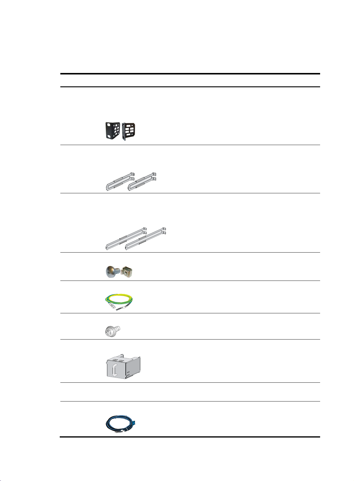
Installation accessories
Table 4 Installation accessories
Product code Description Quantity Applicable models
1 U mounting bracket kit
(including one pair of mounting
brackets and eight M4
5066-0850
5185-8681
5185-8713
countersunk screws)
1 U short slide rail kit (including
one pair of slide rails and four M4
countersunk screws)
1 U long slide rail kit (including
one pair of slide rails, one pair of
guide rails, and four M4
countersunk screws)
1 kit All 5700 switches
1 kit All 5700 switches
• HP 5700-48G-4XG-2QSFP+
• HP 5700-48G-4XG-2QSFP+
Optional
TAA
• HP 5700- 40XG-2QSFP+
• HP 5700- 40XG-2QSFP+
TAA
M6 screw and floating nut
N/A
Grounding cable
5184-6723
5185-9579
5185-8676
N/A AC power cord User supplied
5185-8688
Grounding screw
Power supply filler module
DC power cord
User supplied All 5700 switches
1 All 5700 switches
2 All 5700 switches
1 All 5700 switches
1
• 300 W AC power supply
• 650 W AC power supply
• 300 W DC power supply
• 650 W DC power supply
5
Page 10

Product code Description Quantity Applicable models
Removable cable tie
5185-8748
Console cable
1 All power supplies
5185-8627
5185-8722
5187-9022
1 All 5700 switches
SFP/SFP+ dust plug
Optional All 5700 switches
QSFP+ dust plug
Optional All 5700 switches
6
Page 11
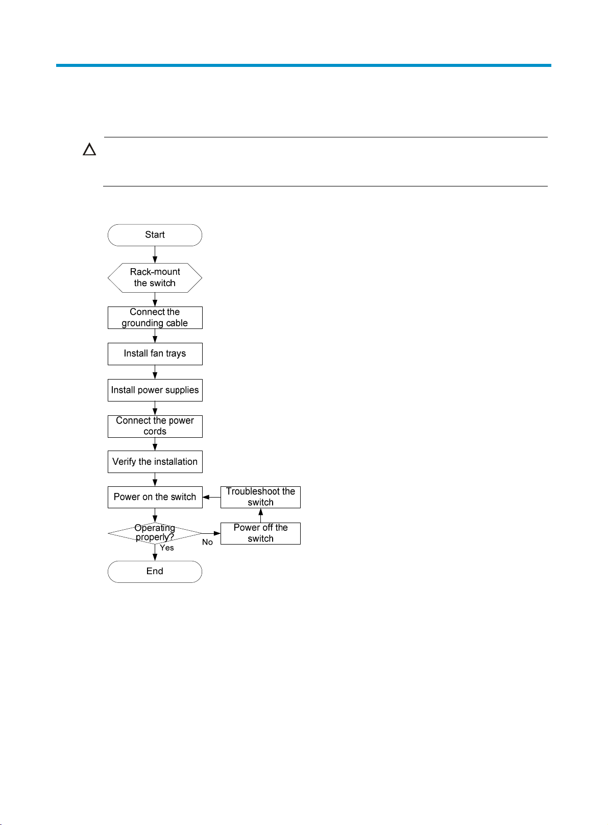
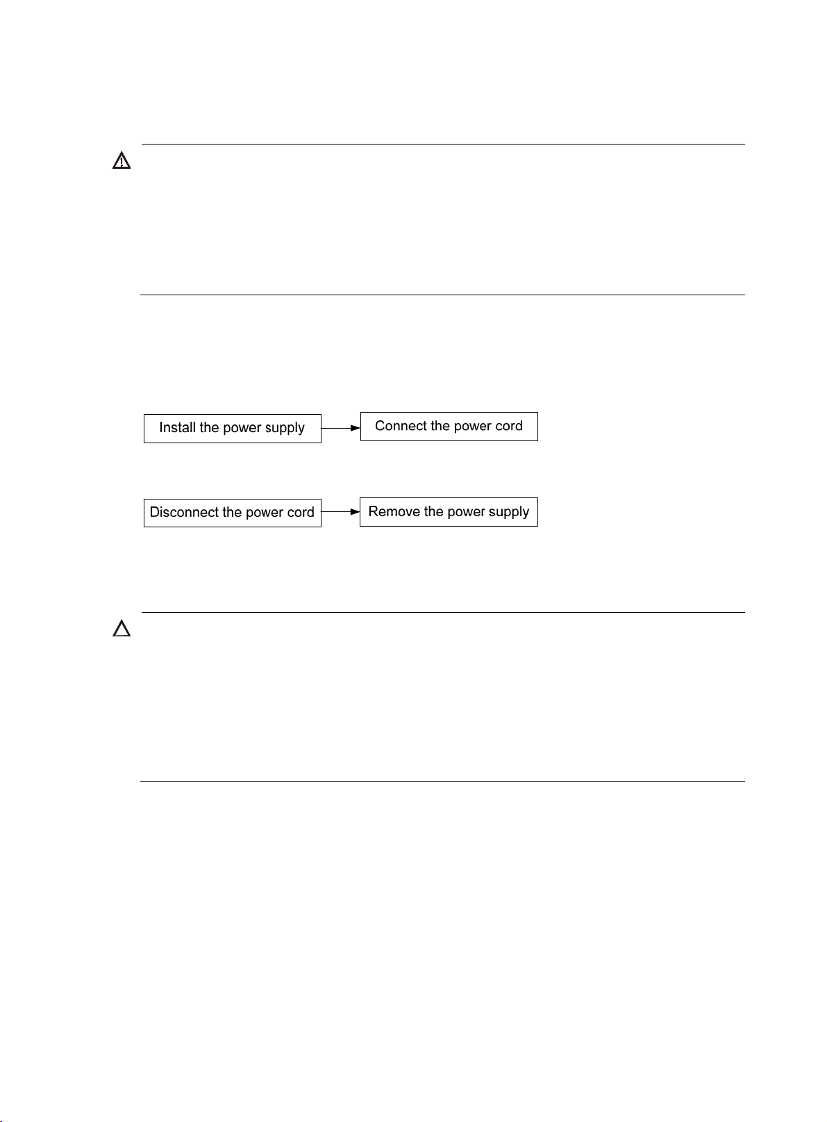
Installing the switch
g
CAUTION:
Keep the tamper-proof seal on a mountin
chassis, contact HP for permission. Otherwise, HP shall not be liable for any consequence caused thereby.
Figure 1 Hardware installation flow
screw on the chassis cover intact, and if you want to open the
Installing the switch in a 19-inch rack
Installation prerequisites
To close the rack door easily, make sure the rack depth for the HP 5700-32XGT-8XG-2QSFP+ and HP
5700-32XGT-8XG-2QSFP+ TAA switches is a minimum of 1000 mm (39.37 in).
The distance from the front to the rear posts of the rack must meet the requirements described in Table 5.
Y
ou must use both the mounting bracket and the rack mounting rail kit to rack-mount the switch.
7
Page 12
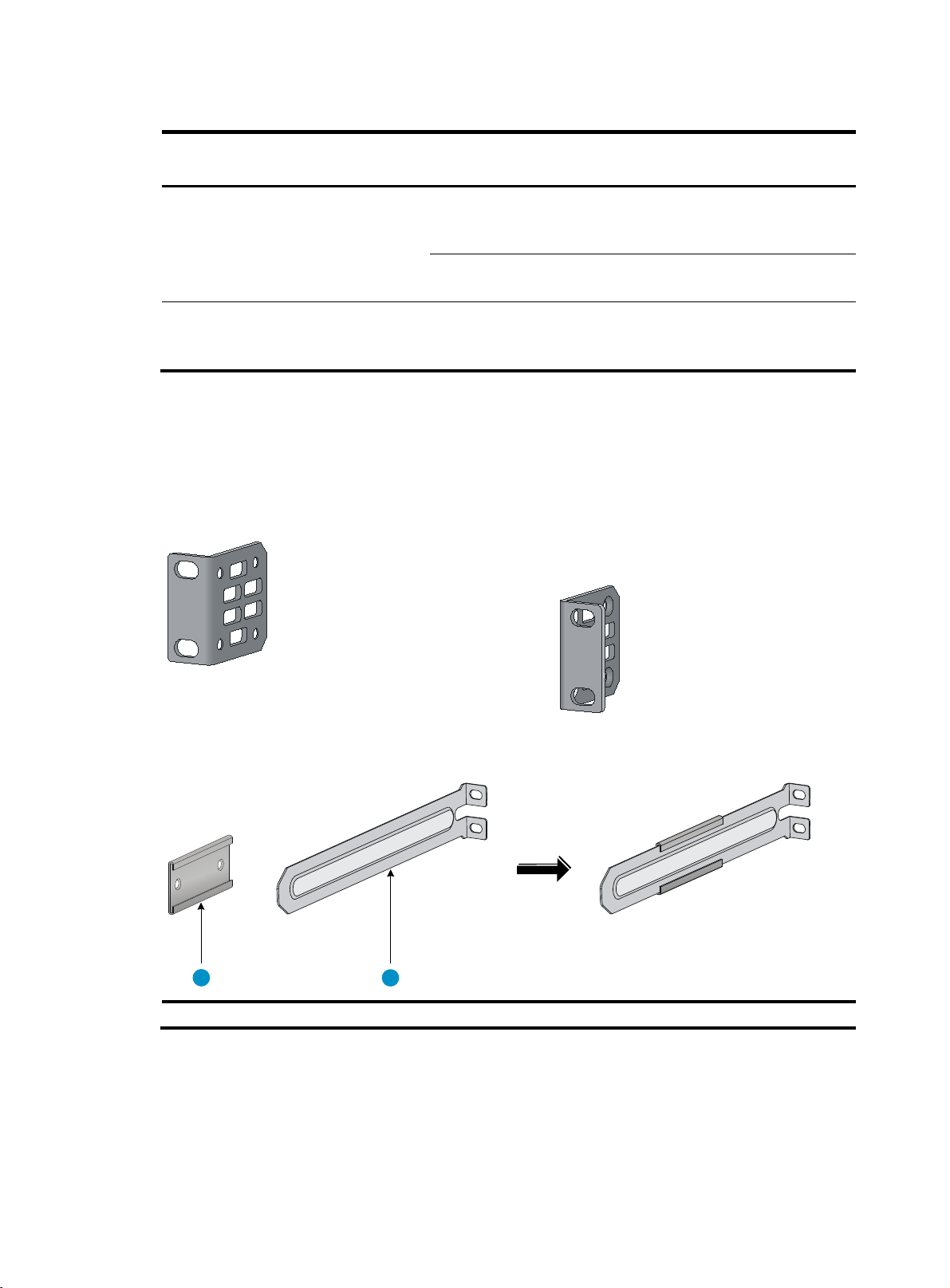
Table 5 Requirements for the distance from the front to rear posts
Switch model Installation method
• HP 5700-48G-4XG-2QSFP+
• HP 5700-48G-4XG-2QSFP+ TAA
Using mounting brackets and
short slide rails (supplied with
the switch)
Minimum
distance
401 mm
(15.79 in)
• HP 5700- 40XG-2QSFP+
• HP 5700- 40XG-2QSFP+ TAA
• HP 5700-32XGT-8XG-2QSFP+
• HP 5700-32XGT-8XG-2QSFP+ TAA
Using mounting brackets and
long slide rails (optional)
Using mounting brackets and
short slide rails (supplied with
the switch)
621 mm
(24.45 in)
405 mm
(15.94 in)
Mounting brackets and rack mounting rail kit
The switch comes with a pair of mounting brackets (see Figure 2) and a rack mounting kit that includes
a pair of chassis rails and a pair of slide rails (see Figure 3).
Figure 2 1U mounting bracket kit
Maximum
distance
654 mm
(25.75 in)
874 mm
(34.41 in)
854 mm
(33.62 in)
Figure 3 Rack mounting rail kit
1 2
(1) Chassis rail (2) Slide rail
8
Page 13
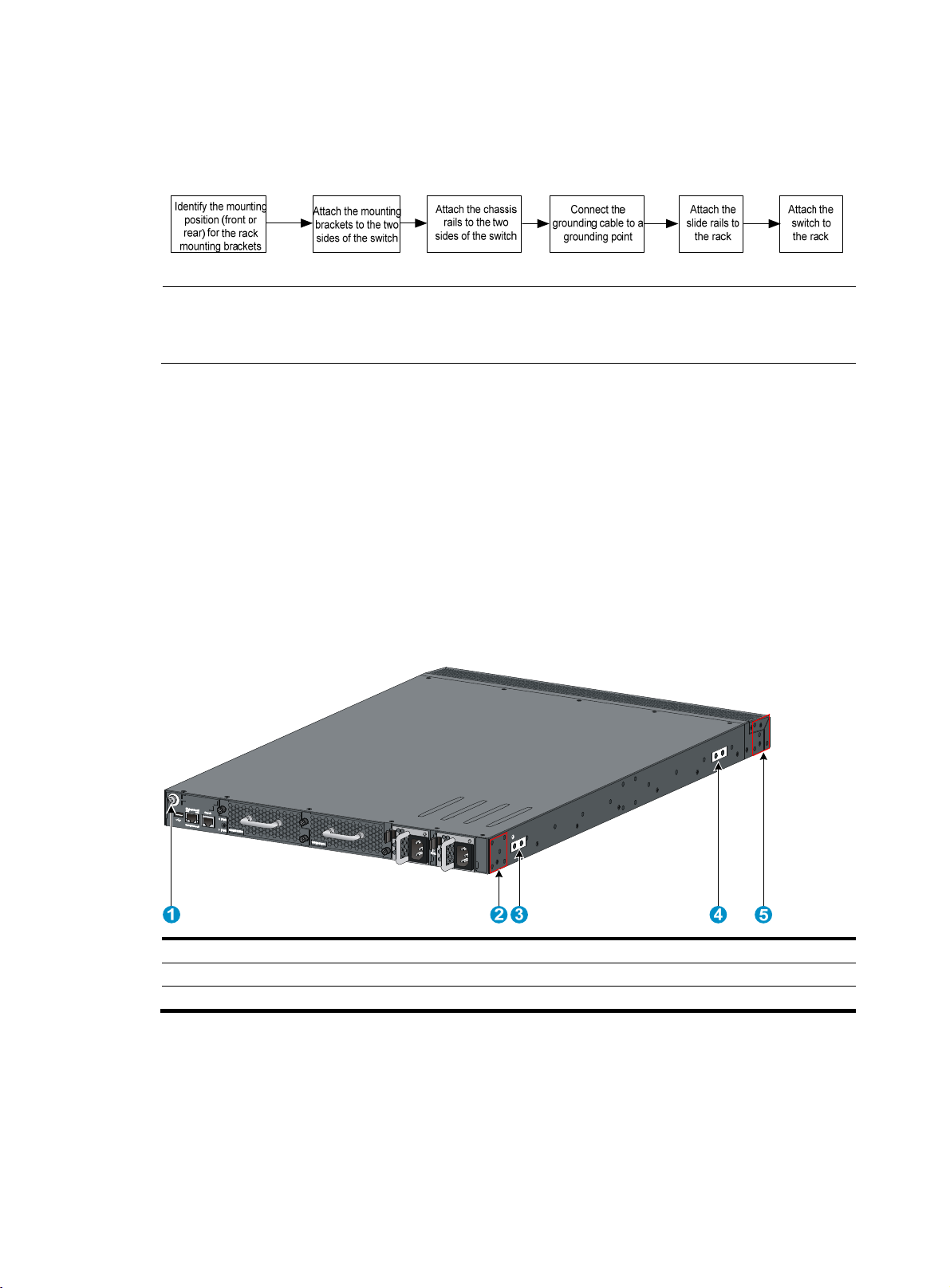
Rack-mounting procedures at a glance
Figure 4 Rack-mounting procedure
NOTE:
If a rack shelf is available, you can put the switch on the rack shelf, slide the switch to an appropriate
location, and attach the switch to the rack with the mounting brackets.
Attaching the mounting brackets, chassis rails, and grounding cable to the chassis
The switch has one front mounting position (near the network ports) and one rear mounting position (near
the power supplies).
The switch has one primary grounding point (with a grounding sign) and two auxiliary grounding points.
Use the primary grounding point whenever possible. If the primary grounding point fails or is not suitable
for the installation site, use one of the auxiliary grounding points.
Figure 5 Mounting and grounding positions of the HP 5700-32XGT-8XG-2QSFP+/HP
5700-32XGT-8XG-2QSFP+ TAA switch
(1) Auxiliary grounding point 2 (2) Rear mounting position
(3) Primary grounding point (4) Auxiliary grounding point 1
(5) Front mounting position
9
Page 14
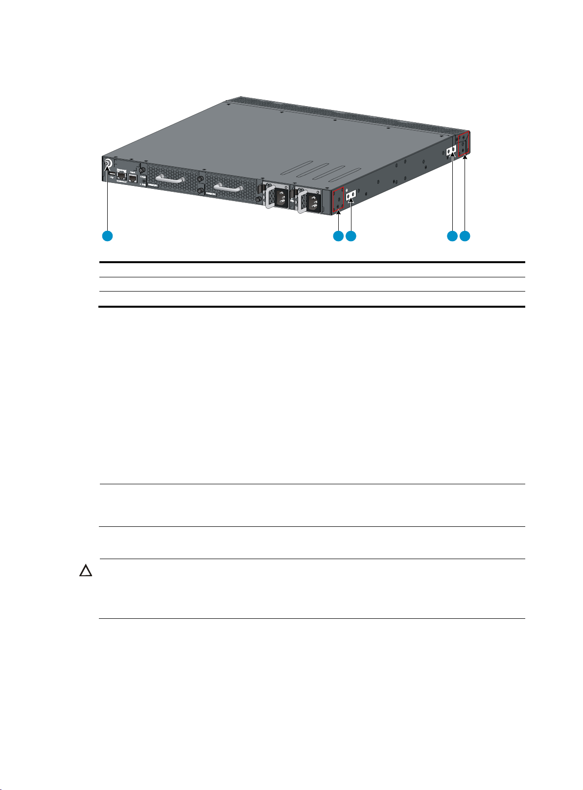
Figure 6 Mounting and grounding positions of the HP 5700-48G-4XG-2QSFP+/HP
A
5700-48G-4XG-2QSFP+ TAA/HP 5700-40XG-2QSFP+/HP 5700-40XG-2QSFP+ TAA switch
1 2 3 4 5
(1) Auxiliary grounding point 2 (2) Rear mounting position
(3) Primary grounding point (4)
(5) Front mounting position
uxiliary grounding point 1
Attaching the mounting brackets and chassis rails to the chassis
1. Align the mounting brackets with the screw holes in the rear mounting position (see Figure 7) or
front mounting position (see Figure 8).
2. Use M4
screws (supplied with the switch) to attach the mounting brackets to the chassis.
3. Align the chassis rails with the rail mounting holes in the chassis:
{ If the mounting brackets are in the rear mounting position, align the chassis rails with the screw
holes at the front of the side panels (see Figure 7).
{ If the mounting brackets are in the front mounting position, align the chassis rails with the screw
holes at the rear of the side panels (see Figure 8).
4. Use M4 screws (supplied with the switch) to attach the chassis rails to the chassis.
NOTE:
Secure the mounting brackets and chassis rails to both sides of the chassis in the same way.
Connecting the grounding cable to the chassis
CAUTION:
The primary grounding point and auxiliary grounding point 1 are located on the left side panel. If you use
one of these grounding points, you must connect the grounding cable to the grounding point before you
mount the switch in the rack.
To connect the grounding cable to a chassis grounding point, for example, the primary grounding point:
1. Choose a grounding point.
2. Unpack the grounding cable and grounding screws.
3. Align the two-hole grounding lug at one end of the cable with the grounding holes of the
grounding point, insert the grounding screws into the holes, and tighten the screws with a
screwdriver to attach the grounding lug to the chassis, as shown in Figure 7.
10
Page 15
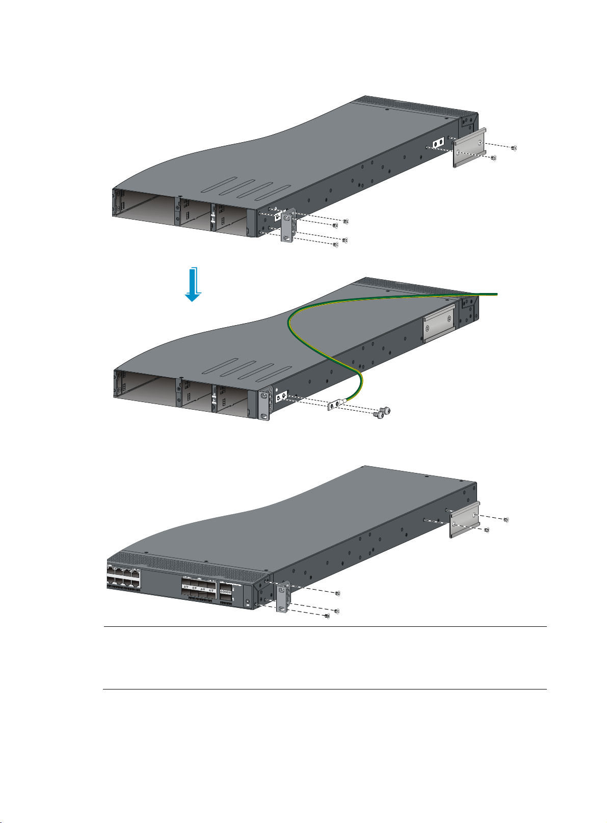
Figure 7 Attaching the rear mounting brackets/chassis rails/grounding cable to the chassis
g
g
Figure 8 Attaching the front mounting brackets/chassis rails to the chassis
NOTE:
HP recommends that you use the primary grounding point or auxiliary grounding point 1 because the
grounding cable and grounding screw that come with the switch are suitable only for these two
points.
roundin
11
Page 16
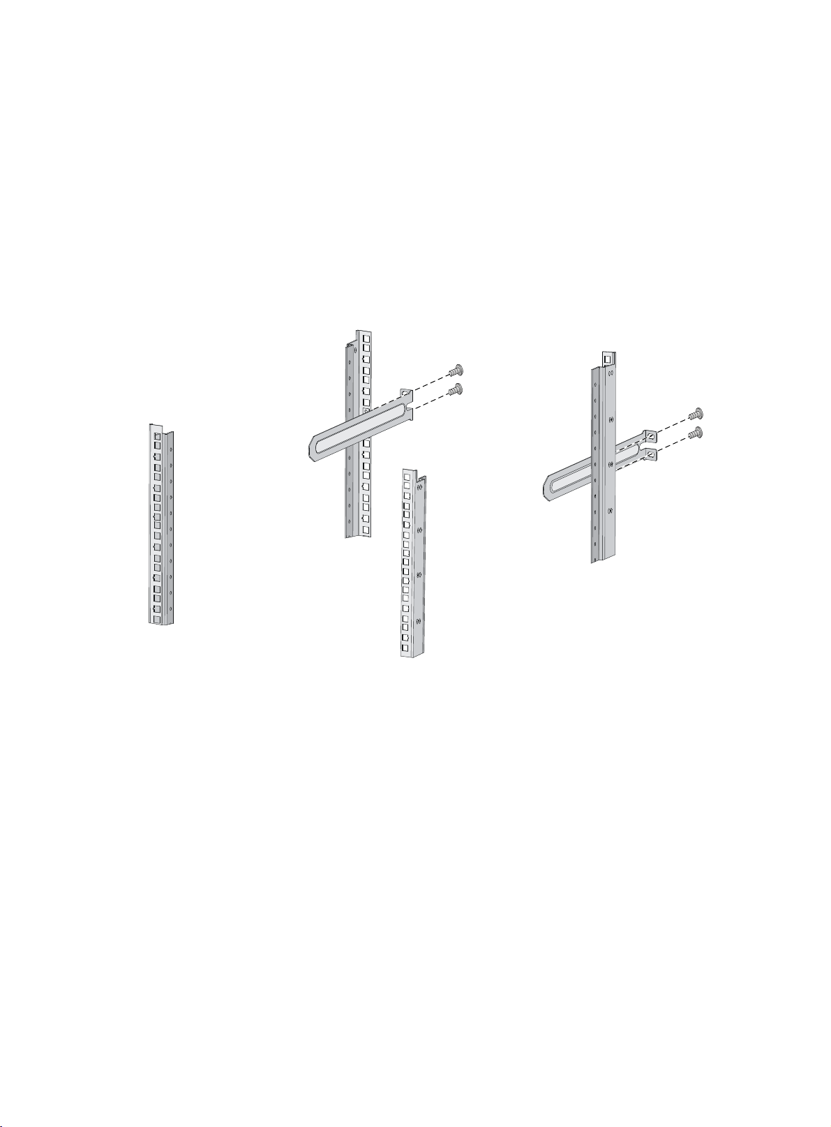
Attaching the slide rails to the rack
1. Identify the rack attachment position for the slide rails, and mark cage nut installation positions on
the rack posts.
2. Install cage nuts (user-supplied) in the mounting holes in the rack posts.
3. Align the screw holes in one slide rail with the cage nuts in the rack post on one side, and use
screws (user supplied) to attach the slide rail to the rack, as shown in Figure 9.
4. Repeat the pr
Keep the two slide rails at the same height so the slide rails can attach into the chassis rails.
Figure 9 Installing the slide rails
eceding step to attach the other slide rail to the rack post on the other side.
Mounting the switch in the rack
This task requires two people.
To mount the switch in the rack:
1. Wear an ESD wrist strap and make sure it makes good skin contact and is well grounded.
2. Verify that the mounting brackets and chassis rails have been securely attached to the switch
chassis.
3. Verify that the slide rails have been correctly attached to the rear rack posts.
4. Install cage nuts (user-supplied) to the front rack posts and make sure they are at the same level as
the slide rails.
5. Supporting the bottom of the switch, align the chassis rails with the slide rails on the rack posts, as
shown in Figure 10. Work with another person to slid
the mounting brackets are flush with the rack posts.
6. Use screws (user-supplied) to attach the mounting brackets to the rack, as shown in Figure 11.
12
e the chassis rails along the slide rails until
Page 17
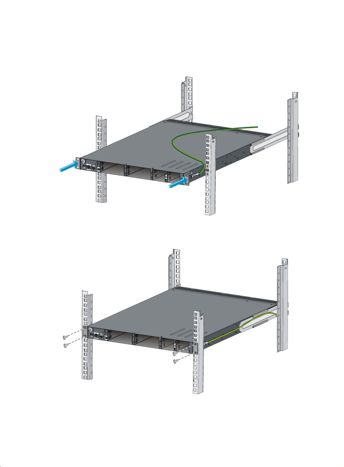
To secure the switch in the rack, make sure the front ends of the slide rails reach out of the chassis
rails.
Figure 10 Mounting the switch in the rack (1)
Figure 11 Mounting the switch in the rack (2)
13
Page 18

Grounding the switch
W
W
g
ARNING!
Correctly connecting the switch grounding cable is crucial to lightning protection and EMI protection.
The power input end of the switch has a noise filter, whose central ground is directly connected to the
chassis to form the chassis ground (commonly known as PGND). You must securely connect this chassis
ground to the earth so the faradism and leakage electricity can be safely released to the earth to
minimize EMI susceptibility of the switch.
You can ground a switch by using a grounding strip at the installation site or the AC power cord
connected to the switch.
NOTE:
The power and grounding terminals in this section are for illustration only.
Grounding the switch with a grounding strip
ARNING!
Connect the
main or lightning rod.
rounding cable to the grounding system in the equipment room. Do not connect it to a fire
If a grounding strip is available at the installation site, connect the grounding cable to the grounding
strip.
To connect the grounding cable:
1. Attach the two-hole grounding lug at one end of the grounding cable to a grounding point on the
switch chassis (see "Connecting the grounding cable to the chassis").
2. Remove the hex nut of a grounding post on the grounding strip.
3. Attach the ring terminal at the other end of the grounding cable to the grounding strip through the
grounding post, and fasten the ring terminal with the removed hex nut.
14
Page 19

Figure 12 Connecting the grounding cable to a grounding strip
g
g
t
1 2 3 4
(1) Hex nut (2) Rin
(3) Grounding post
(4) Grounding strip
terminal
NOTE:
• HP recommends that you use the primary grounding point or auxiliary grounding point 1, because the
grounding cable and grounding screw provided with the switch are applicable only to these two
grounding points.
• To use auxiliary grounding point 2 on the switch, prepare a grounding cable yourself. The connection
method is the same as connecting to the other two grounding points.
Grounding the switch by using the AC power cord
If the installation site has no grounding strips, you can ground an AC-powered switch through the
protective earth (PE) wire of the power cord, but must make sure:
• The power cord has a PE terminal.
• The ground contact in the power outlet is securely connected to the ground in the power distribution
room or on the AC transformer side.
• The power cord is securely connected to the power outlet.
NOTE:
round contact in the power outlet is not connected to the ground, report the problem and reconstruc
If the
the grounding system.
15
Page 20

Figure 13 Grounding through the PE wire of the AC power cord
1
(1) Three-wire AC power cable (2) Chassis rear panel
NOTE:
To guarantee the grounding effect, use the grounding cable provided with the switch to connect to the
grounding strip in the equipment room as long as possible.
Installing/removing a fan tray
CAUTION:
To ensure good ventilation for the switch:
• Install two fan trays of the same model on the switch.
2
• Do not operate the system with one failed fan tray for more than 24 hours.
• Do not remove the failed fan tray until you are ready for replacing it.
• Do not operate the system without any fan tray for more than 2 minutes.
• Do not operate the system outside of the temperature range 0°C to 45°C (32°F to 113°F) degrees.
NOTE:
• The fan trays in the HP 5700-48G-4XG-2QSFP+, HP 5700-48G-4XG-2QSFP+ TAA, HP
5700-40XG-2QSFP+, and HP 5700-40XG-2QSFP+ TAA switches must be the same type:
LSWM1FANSC or LSWM1FANSCB.
• The fan trays in the HP 5700-32XGT-8XG-2QSFP+ and HP 5700-32XGT-8XG-2QSFP+ TAA switches
must be the same type: LSWM1HFANSC or LSWM1HFANSCB.
16
Page 21
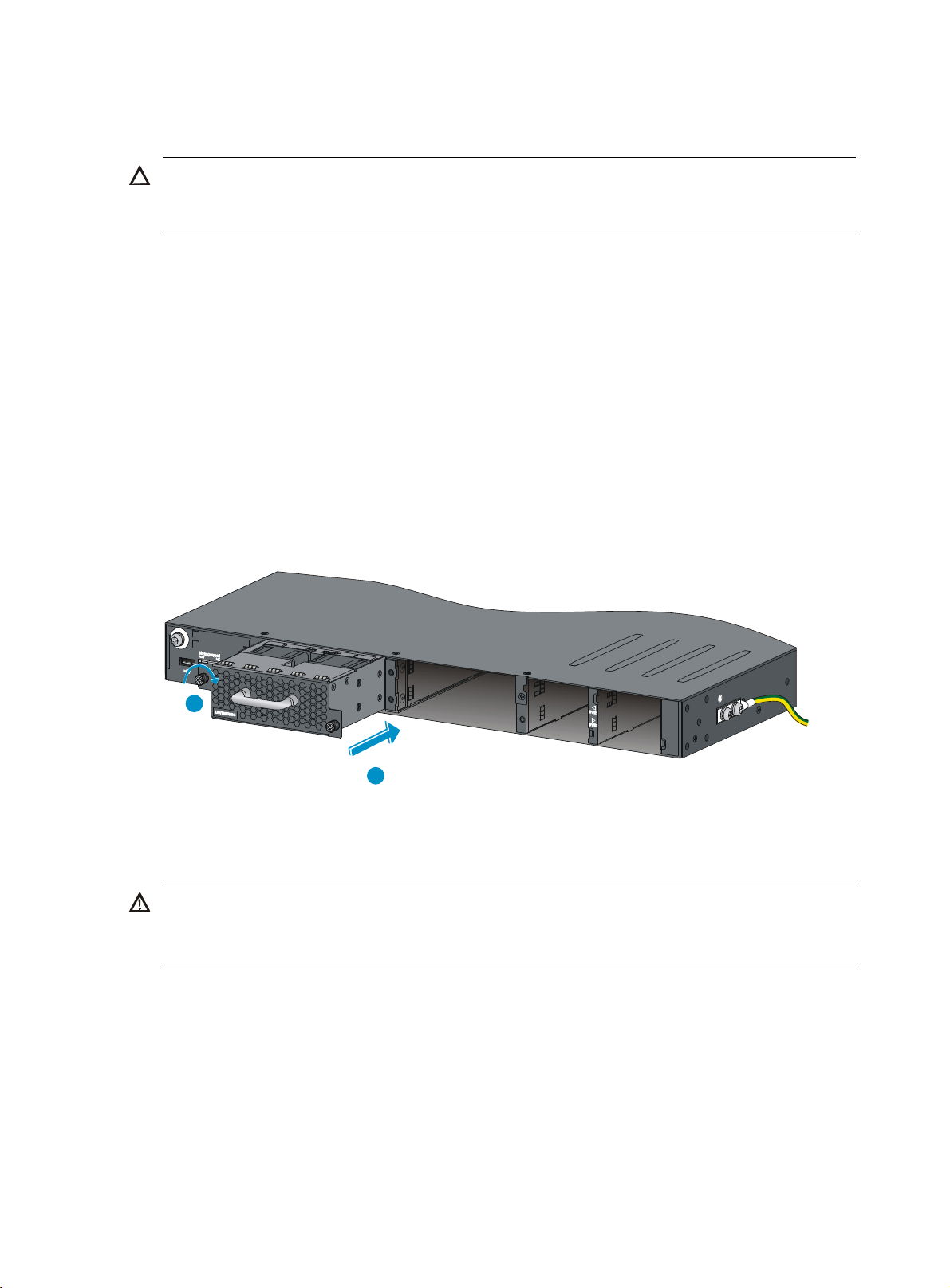
Installing a fan tray
W
CAUTION:
To prevent damage to the fan tray or the connectors on the backplane, insert the fan tray gently. If you
encounter a hard resistance while inserting the fan tray, pull out the fan tray and insert it again.
Select appropriate fan trays as needed. For the optional fan trays and their specifications, see "Fan
trays."
To install a fan tray:
1. Wear an ESD wrist strap and make sure it makes good skin contact and is well grounded.
2. Unpack the fan tray and verify that the fan tray model is correct.
3. Grasp the handle of the fan tray with one hand and support the fan tray bottom with the other, and
slide the fan tray along the guide rails into the slot until the fan tray seats in the slot and has a firm
contact with the backplane (see callout 1 in Figure 14).
4. Fasten the
attached in the chassis (see callout 2 in Figure 14).
If the captive screw cannot be tightly fastened, verify the installation of the fan tray.
Figure 14 Installing a fan tray
2
captive screw on the fan tray with a Philips screwdriver until the fan tray is securely
Removing a fan tray
ARNING!
• Take out the fan tray after the fans completely stop rotating.
1
• To avoid an unbalanced fan causing loud noise, do not touch the fans, even if they are not rotating.
To remove a fan tray:
1. Wear an ESD wrist strap and make sure it makes good skin contact and is well grounded.
2. Loosen the captive screw of the fan tray with a Philips screwdriver until it is fully disengaged from
the switch chassis.
3. Grasp the handle of the fan tray with one hand and pull the fan tray part way out the slot. Support
the fan tray bottom with the other hand, and pull the fan tray slowly along the guide rails out of the
slot.
4. Put away the removed fan tray in an antistatic bag for future use.
17
Page 22
Installing/removing a power supply
W
g
t
ARNING!
• The switch does not support intermixing of AC and DC power supplies.
• HP 5700-48G-4XG-2QSFP+ and HP 5700-48G-4XG-2QSFP+ TAA switches do not support
intermixing of 300 W and 650 W power supplies.
• In power redundancy mode, you can replace a power supply without powerin
strictly follow the installation and procedures in Figure 15 and Figure 16 to avoid any bodily injury or
damage to the switch.
The switch comes with both power supply slots empty and the power filler modules as accessories.
You can install one or two power supplies for these switches as needed. For more information about the
power supplies available for the switches, see "Power supplies."
Figure 15 Installation pr
Figure 16 Removal procedure
ocedure
Installing a power supply
CAUTION:
• Follow the forward inertia of the power supply when inserting it into the chassis, and make sure the
power supply has firm contact with the connectors on the backplane.
off the switch but mus
• To prevent damage to the connectors inside the switch chassis, insert the power supply gently. If you
encounter a hard resistance while inserting the power supply, pull out the power supply and insert it
again.
• If only one power supply is installed, install a power filler module in the empty power supply slot for
good ventilation of the switch.
To install a 300 W AC power supply, 300 W DC power supply, 650 W AC power supply, or 650 W
DC power supply into the switch:
1. Wear an ESD wrist strap and make sure it makes good skin contact and is well grounded.
2. Unpack the power supply and verify that the power supply model is correct.
3. Correctly orient the power supply with the power supply slot (see Figure 17), grasp
the power supply with one hand and support its bottom with the other, and slide the power supply
slowly along the guide rails into the slot.
The slot is foolproof. If you cannot insert the power supply into the slot, re-orient the power supply
rather than use excessive force to push it in.
18
the handle of
Page 23

Figure 17 Installing a power supply
Figure 18 Installing a power supply filler module
Removing a power supply
CAUTION:
If the switch has two power supplies, removing one power supply does not affect the operation of the
switch. If the switch has only one power supply, removing the power supply powers off the switch.
To remove a 300 W AC power supply, 300 W DC power supply, 650 W AC power supply, or 650 W
DC power supply from the switch:
1. Wear an ESD wrist strap and make sure it makes good skin contact and is well grounded.
2. Squeeze the tabs on the power cord connector with your thumb and forefinger, and pull the
connector out to remove the power cord, as shown in Figure 19.
3. Hold the handle on the power supply with one hand,
right with your thumb, and pull the power supply part way out of the slot, as shown in Figure 20.
4. Su
5. Put away the removed power supply in an antistatic bag for future use.
pporting the power supply bottom with one hand, slowly pull the power supply out with the other
hand.
pivot the latch on the power supply to the
19
Page 24

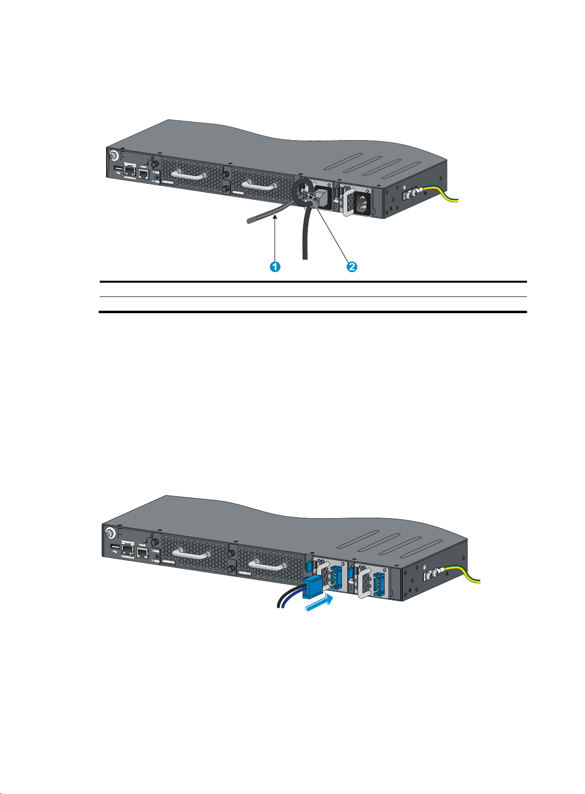
Figure 19 Removing the DC power cord
(1) Press the tabs on the power cord connector with
your thumb and forefinger
Figure 20 Removing the power supply
(1) Pivot the latch to the right with your thumb
(2) Pull the power cord connector out
(2) Pull the power supply out
Connecting the power cord
Connecting the AC power supply
1. Insert the female connector of the AC power cord supplied with the power supply into the power
receptacle on the power supply.
20
Page 25
2. Use a cable tie to secure the power cord to the handle of the power supply, as shown in Figure 21.
3. Connect the other end of the power cord to an AC power outlet.
Figure 21 Connecting the AC power supply on the HP 5700-40XG-2QSFP+ switch
(1) Cable tie
(2) Tighten the cable tie to secure the power cord to the handle of the power supply
Connecting the DC power supply
1. Unpack the DC power cord, identify the plug for connecting to the power supply, orient the plug
with the power receptacle on the power supply, and insert the plug into the receptacle (see Figure
22).
T
he receptacle is foolproof. If you cannot insert the plug into the receptacle, re-orient the plug
rather than use excessive force to push it in.
2. Use a cable tie to secure the power cord to the handle of the power supply, as shown in Figure 21.
3. Connect the other end of th
Figure 22 Connecting the DC power supply on the HP 5700-40XG-2QSFP+ switch
e power cord to the DC power source.
Verifying the installation
After you complete the installation, verify that:
• There is enough space for heat dissipation around the switch, and the rack is stable.
• The grounding cable is securely connected.
21
Page 26

• The correct power source is used.
• The power cords are correctly connected.
• All the interface cables are cabled indoors. If any cable is routed outdoors, verify that the socket
strip with lightning protection and lightning arresters for network ports have been correctly
connected.
22
Page 27

Accessing the switch for the first time
Setting up the configuration environment
The first time you access the switch you must use a console cable to connect a console terminal, for
example, a PC, to the console port on the switch.
Figure 23 Connecting the console port to a terminal
Connecting the console cable
Console cable
A console cable is an 8-core shielded cable, with a crimped RJ-45 connector at one end for connecting
to the console port of the switch, and a DB-9 female connector at the other end for connecting to the
serial port on the console terminal.
Figure 24 Console cable
A side
Pos.9
A
Pos.1
Connection procedure
Main label
8
1
B side
B
To connect a terminal (for example, a PC) to the switch:
23
Page 28

1. Plug the DB-9 female connector of the console cable to the serial port of the PC.
2. Connect the RJ-45 connector to the console port of the switch.
NOTE:
• Identify the mark on the console port and make sure you are connecting to the correct port.
• The serial ports on PCs do not support hot swapping. If the switch has been powered on, connect the
console cable to the PC before connecting to the switch, and when you disconnect the cable, first
disconnect from the switch.
Setting terminal parameters
To configure and manage the switch, you must run a terminal emulator program on the console terminal.
The following are the required terminal settings:
• Bits per second—9,600
• Data bits—8
• Parity—None
• Stop bits—1
• Flow control—None
• Emulation—VT100
To set terminal parameters, for example, on a Windows XP HyperTerminal:
1. Select Start > All Programs > Accessories > Communications > HyperTerminal.
The Connection Description dialog box appears.
2. Enter the name of the new connection in the Name field and click OK.
Figure 25 Connection description
3. Select the serial port to be used from the Connect using list, and click OK.
24
Page 29

Figure 26 Setting the serial port used by the HyperTerminal connection
4. Set Bits per second to 9600, Data bits to 8, Parity to None, Stop bits to 1, and Flow control to None,
and click OK.
Figure 27 Setting the serial port parameters
5. Select File > Properties in the HyperTerminal window.
25
Page 30

Figure 28 HyperTerminal window
6. On the Settings tab, set the emulation to VT100 and click OK.
Figure 29 Setting terminal emulation in Switch Properties dialog box
26
Page 31

Powering on the switch
Before powering on the switch, verify that the following conditions are met:
• The power cord is correctly connected.
• The input power voltage meets the requirement of the switch.
• The console cable is correctly connected.
• The configuration terminal (a PC, for example) has started, and its serial port settings are consistent
with the console port settings on the switch.
Power on the switch. During the startup process, you can access Boot ROM menus to perform tasks such
as software upgrade and file management. The Boot ROM interface and menu options differ with
software versions. For more information about Boot ROM menu options, see the software-matching
release notes for the device.
After the startup completes, you can access the CLI to configure the switch.
For more information about the configuration commands and CLI, see HP FlexFabric 5700 Switch Series
Configuration Guides and HP FlexFabric 5700 Switch Series Command References.
27
Page 32

Setting up an IRF fabric
You can use HP IRF technology to connect and virtualize HP FlexFabric 5700 switches into a large virtual
switch called an "IRF fabric" for flattened network topology, and high availability, scalability, and
manageability.
IRF fabric setup flowchart
Figure 30 IRF fabric setup flowchart
To set up an IRF fabric:
28
Page 33

Step Description
P
Plan the installation site and IRF fabric setup parameters:
• Planning IRF fabric size and the installation site
1. Plan IRF fabric setup.
2. Install IRF member
switches.
3. Connect ground wires
and power cords.
• Identifying the master switch and planning IRF member IDs
• Planning IRF topology and connections
• Identifying physical IRF ports on the member switches
• Planning the cabling scheme
See "Installing the switch in a 19-inch rack."
See "Grounding the switch" a
nd "Connecting the power cord."
4. Power on the switches.
5. Configure basic IRF
settings.
6. Connect the physical
IRF ports.
N/A
See HP FlexFabric 5700 Switch Series IRF Configuration Guide.
See "Planning IRF topology and connections."
All switches except the master switch automatically reboot, and the IRF fabric is
established.
Planning IRF fabric setup
This section describes issues that an IRF fabric setup plan must cover.
Planning IRF fabric size and the installation site
Choose switch models and identify the number of required IRF member switches, depending on the user
density and upstream bandwidth requirements. The switching capacity of an IRF fabric equals the total
switching capacities of all member switches.
Plan the installation site depending on your network solution as follows:
• Place all IRF member switches in one rack for centralized high-density access.
• Distribute the IRF member switches in different racks to implement the top-of-rack (ToR) access
solution for a data center.
As your business grows, you can plug HP FlexFabric 5700 switches into the IRF fabric to increase the
switching capacity without any topology change or replacement.
Identifying the master switch and planning IRF member IDs
Determin e which swi tch yo u want to use as the master for m anaging all member switches in the IRF fabric.
An IRF fabric has only one master switch. You configure and manage all member switches in the IRF
fabric at the command line interface of the master switch.
NOTE:
IRF member switches will automatically elect a master. You can affect the election result by assigning a
high member priority to the intended master switch. For more information about master election, see
FlexFabric 5700 Switch Series IRF Configuration Guide
29
.
H
Page 34

Prepare an IRF member ID assignment scheme. An IRF fabric uses member IDs to uniquely identify and
manage its members, and you must assign each IRF member switch a unique member ID.
Planning IRF topology and connections
You can create an IRF fabric in daisy chain topology, or more reliably, ring topology. In ring topology,
the failure of one IRF link does not cause the IRF fabric to split as in daisy chain topology. Rather, the IRF
fabric changes to a daisy chain topology without interrupting network services.
You connect the IRF member switches through IRF ports, the logical interfaces for the connections
between IRF member switches. Each IRF member switch has two IRF ports: IRF-port 1 and IRF-port 2. To
use an IRF port, you must bind at least one physical port to it.
When connecting two neighboring IRF member switches, you must connect the physical ports of IRF-port
1 on one switch to the physical ports of IRF-port 2 on the other switch.
The HP 5700-48G-4XG-2QSFP+, HP 5700-48G-4XG-2QSFP+ TAA, HP 5700-40XG-2QSFP+, and HP
5700-40XG-2QSFP+ TAA switches can provide 10-GE and 40-GE IRF connections through SFP+ ports
and QSFP+ ports, respectively.
The HP 5700-32XGT-8XG-2QSFP+ and HP 5700-32XGT-8XG-2QSFP+ TAA switches can provide 10-GE
and 40-GE IRF connections through 1/10-GE Ethernet ports, SFP+ ports, or QSFP+ ports.
You can bind several ports of the same type to an IRF port for increased bandwidth and availability.
Figure 31 and
Figure 32 show the topologies of an IRF fabric made up of three HP FlexFabric 5700
switches. The IRF port connections in the two figures are for illustration only, and more connection
methods are available.
Figure 31 IRF fabric in daisy chain topology
30
Page 35

Figure 32 IRF fabric in ring topology
1
2
3
IRF-port1
IRF-port2
1
IRF-port2
IRF-port1
IRF-port2
2 3
IRF-port1
Identifying physical IRF ports on the member switches
Identify the ports to be used for IRF connections on the member switches according to your topology and
connection scheme.
All ports on the front panel of the HP FlexFabric 5700 switch can be used for IRF connections.
Follow these guidelines when you identify 1/10-GE Ethernet ports and SFP+ ports to be used for IRF
connections:
• On the HP 5700-40XG-2QSFP+ and HP 5700-40XG-2QSFP+ TAA switches, the SFP+ ports are
grouped by port number in ascending order, starting from one. Every four SFP+ ports form one
group.
• On the HP 5700-32XGT-8XG-2QSFP+ and HP 5700-32XGT-8XG-2QSFP+TAA switches, the
1/10-GE Ethernet ports and SFP+ ports are grouped by port number in ascending order, starting
from 1 for 1/10-GE Ethernet ports and 33 for SFP+ ports, respectively. Every four ports form one
group.
• On the HP 5700-48G-4XG-2QSFP+ and HP 5700-48G-4XG-2QSFP+ TAA switches, SFP+ ports
numbered 49, 50, 51, and 52 form one group.
• A port can be bound to an IRF port or operate as a service port. When a port is bound to an IRF
port, other ports in the same port group cannot be used as service ports, and vice versa.
A common practice is to use one 1/10-GE Ethernet port/SFP+ port group for IRF connections, and bind
every two ports in the group to an IRF port for increased bandwidth and availability.
Planning the cabling scheme
Follow these guidelines when you use cables to connect switches:
• HP 5700-48G-4XG-2QSFP+, HP 5700-48G-4XG-2QSFP+ TAA, HP 5700-40XG-2QSFP+, and HP
5700-40XG-2QSFP+ TAA switches—Use SFP+/QSFP+ cables or SFP+/QSFP+ transceiver
modules and fibers.
31
Page 36

• HP 5700-32XGT-8XG-2QSFP+ and HP 5700-32XGT-8XG-2QSFP+ TAA switches—Use Category 6
or higher twisted pair cables, SFP+/QSFP+ cables, or SFP+/QSFP+ transceiver modules and
fibers.
If the IRF member switches are far away from one another, choose the SFP+/QSFP+ transceiver modules
with optical fibers. If the IRF member switches are all in one equipment room, choose Category 6 or
higher twisted pair/SFP+/QSFP+ cables. For more information about available SFP+/QSFP+ cables
and transceiver modules, see "SFP+ port" and "QSFP+ port."
The following subsections describe several HP recommended IRF connection schemes, and all these
schemes use a ring topology.
Connecting the IRF member switches in one rack
Use short-haul and long-haul SFP+ cables to connect the IRF member switches (four switches in this
example) in a rack as shown in Figure 33. T
same order as connected in the rack.
Figure 33 Connecting the switches in one rack
he switches in the ring topology (see Figure 34) are in the
1
2
3
4
Figure 34 IRF fabric topology
Connecting the IRF member switches in a ToR solution
You can install IRF member switches in different racks side by side to deploy a top of rack (ToR) solution.
32
Page 37

Figure 35 shows an example for connecting four top of rack IRF member switches by using SFP+/QSFP+
W
cables, and SFP+/QSFP+ transceiver modules, and optical fibers. The topology is the same as Figure
34.
Figure 35 ToR cabling
Configuring basic IRF settings
After you install the IRF member switches, power on the switches, and log in to each IRF member switch
(see HP FlexFabric 5700 Switch Series Fundamentals Configuration Guide) to configure their member IDs,
member priorities, and IRF port bindings.
Follow these guidelines when you configure the switches:
• Assign the master switch higher member priority than any other switch.
• Bind physical ports to IRF port 1 on one switch and to IRF port 2 on the other switch. You perform
IRF port binding before or after connecting IRF physical ports depending on the software release.
• To bind the ports on an interface card to an IRF port, you must install the interface card first. For how
to install an interface card, see HP FlexFabric 5700 Switch Series Interface Cards User Guide.
• Execute the display irf configuration command to verify the basic IRF settings.
For more information about configuring basic IRF settings, see HP FlexFabric 5700 Switch Series IRF
Configuration Guide.
Connecting the physical IRF ports
Use Category 6 or higher twisted-pair/SFP+/QSFP+ cables or SFP+/QSFP+ transceiver modules and
fibers to connect the IRF member switches as planned.
NOTE:
ear an ESD wrist strap when you connect SFP+ cables or SFP+ transceiver modules and fibers. For more
information, see
Modules/Cables Installation Guide
SFP/SFP+/XFP Transceiver Modules Installation Guide and QSFP+ Transceiver
.
Accessing the IRF fabric to verify the configuration
To verify the basic functionality of the IRF fabric after you finish configuring basic IRF settings and
connecting IRF ports:
1. Log in to the IRF fabric through the console port of any member switch.
2. Create a Layer 3 interface, assign it an IP address, and make sure the IRF fabric and the remote
network management station can reach each other.
33
Page 38

3. Use Telnet, web, or SNMP to access the IRF fabric from the network management station. (See HP
FlexFabric 5700 Switch Series Fundamentals Configuration Guide.)
4. Verify that you can manage all member switches as if they were one node.
5. Display the running status of the IRF fabric by using the commands in Table 6.
Table 6 Displaying and maintaining IRF configuration and runni
ng status
Task Command
Display information about the IRF fabric. display irf
Display all members’ IRF configurations that take
effect at a reboot.
Display IRF fabric topology information. display irf topology
display irf configuration
NOTE:
To avoid IP address collision and network problems, configure at least one multi-active detection (MAD)
mechanism to detect the presence of multiple identical IRF fabrics and handle collisions. For more
information about MAD detection, see
HP FlexFabric 5700 Switch Series IRF Configuration Guide
.
34
Page 39

Maintenance and troubleshooting
Power supply failure
You can use the LEDs on the power supply to identify a power supply failure. For more information about
the LEDs on a power supply, see HP A58x0AF 300W AC (JG900A) & 300W DC (JG901A) Power
Supplies User Guide and HP A58x0AF 650W AC (JC680A) & 650W DC (JC681A) Power Supplies
User Guide.
The LEDs on the power supply are steady green (active) or flashing green (standby) while the power
supply system is correctly operating. If the LEDs behave in any other way, verify the following items:
• The switch power cord is correctly connected.
• The power source meets the requirement.
• The operating temperature of the switch is in the normal range and the power supply has good
ventilation.
If the problem persists, contact the HP technical support for help.
To replace a power supply, see "Installing/removing a power supply."
Fan tray failure
CAUTION:
• Install two fan trays of the same model on the switch.
• Do not operate the system with one failed fan tray for more than 24 hours.
• Do not remove the failed fan tray until you are ready for replacing it.
• Do not operate the system without any fan tray for more than 2 minutes.
• Do not operate the system outside of the temperature range 0°C to 45°C (32°F to 113°F) degrees.
When a fan tray has problems, the system status LED is steady red and the system outputs alarm
messages.
To replace a failed fan tray, see "Installing/removing a fan tray."
Configuration terminal problems
If the configuration environment setup is correct, the configuration terminal displays booting information
when the switch is powered on. If the setup is incorrect, the configuration terminal displays nothing or
garbled text.
No terminal display
If the configuration terminal displays nothing when the switch is powered on, verify the following items:
35
Page 40

• The power supply is supplying power to the switch.
• The console cable is correctly connected.
• The console cable has no problem and the terminal settings are correct.
Garbled terminal display
If terminal display is garbled, verify that the following settings are configured for the terminal, for
example, HyperTerminal:
• Baud rate—9,600
• Data bits—8
• Parity—none
• Stop bits—1
• Flow control—none
• Emulation—VT100
36
Page 41
Appendix A Chassis views and technical specifications
Chassis views
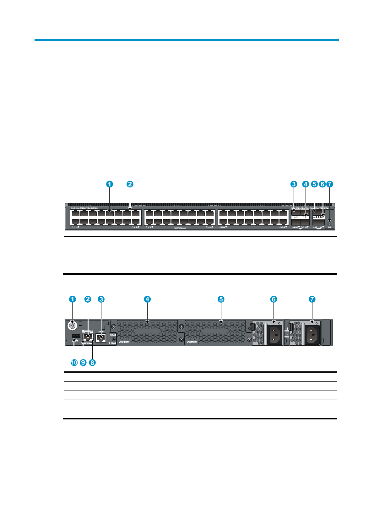
HP 5700-48G-4XG-2QSFP+/HP 5700-48G-4XG-2QSFP+ TAA
Figure 36 Front panel
(1) 10/100/1000Base-T autosensing Ethernet port (2) 10/100/1000Base-T autosensing Ethernet port LED
(3) SFP+ port (4) SFP+ port LED
(5) QSFP+ port (6) QSFP+ port LED
(7) System status LED (SYS)
Figure 37 Rear panel
(1) Grounding screw (auxiliary grounding point 2) (2) Management Ethernet port
(3) Console port (4) Fan tray slot 1
(5) Fan tray slot 2
(7) Power supply slot 2 (8) LINK LED for the management Ethernet port
(9) ACT LED for the management Ethernet port
(6) Power supply slot 1
(10) USB port
The HP 5700-48G-4XG-2QSFP+ and HP 5700-48G-4XG-2QSFP+ TAA switches come with the power
supply slots empty and the filler modules for the slots as accessories. You can install one or two power
supplies for the switch as needed. In Figure 37, t
information about installing and removing a power supply, see "Installing/removing a power supply."
wo 650 W AC power supplies are installed. For more
37
Page 42

The HP 5700-48G-4XG-2QSFP+ and HP 5700-48G-4XG-2QSFP+ TAA switches also come with the fan
tray slots empty. You must install two fan trays of the same model for the switch. In Figure 37, t
LSWM1FANSC fan trays are installed. For more information about installing and removing a fan tray,
see "Installing/removing a fan tray."
Figure 38 Left side panel
(1) Primary grounding point (2) Auxiliary grounding point 1
HP 5700-40XG-2QSFP+/HP 5700-40XG-2QSFP+ TAA
Figure 39 Front panel
wo
(1) SFP+ port (2) SFP+ port LED
(3) QSFP+ port (4) QSFP+ port LED
(5) System status LED (SYS)
Figure 40 Rear panel
(1) Grounding screw (auxiliary grounding point 2)
(3) Fan tray slot 1
(5) Power supply slot 1 (6) Power supply slot 2
(7) Console port (8) LINK LED for the management Ethernet port
(9) ACT LED for the management Ethernet port
(2) Management Ethernet port
(4) Fan tray slot 2
(10) USB port
The HP 5700-40XG-2QSFP+ and HP 5700-40XG-2QSFP+ TAA switches come with the power supply
slots empty and the filler modules for the slots as accessories. You can install one or two power supplies
38
Page 43

for the switch as needed. In Figure 40, two 300 W AC power supplies are installed. For more
information about installing and removing a power supply, see "Installing/removing a power supply."
T
he HP 5700-40XG-2QSFP+ and HP 5700-40XG-2QSFP+ TAA switches also come with the fan tray
slots empty. You must install two fan trays of the same model for the switch. In Figure 40, t
LSWM1FANSC fan trays are installed. For more information about installing and removing a fan tray,
see "Installing/removing a fan tray."
Figure 41 Left side panel
(1) Primary grounding point (2) Auxiliary grounding point 1
HP 5700-32XGT-8XG-2QSFP+/HP 5700-32XGT-8XG-2QSFP+ TAA
wo
Figure 42 Front panel
(1) 1/10GBase-T autosensing Ethernet port
(3) SFP+ port (4) SFP+ port LED
(5) QSFP+ port (6) QSFP+ port LED
(7) System status LED (SYS)
(2) 1/10GBase-T autosensing Ethernet port LED
Figure 43 Rear panel
(1) Grounding screw (auxiliary grounding point 2)
(3) Fan tray slot 1 (4) Fan tray slot 2
(5) Power supply slot 1 (6) Power supply slot 2
(7) Console port (8) LINK LED for the management Ethernet port
39
(2) Management Ethernet port
Page 44

(9) ACT LED for the management Ethernet port
(10) USB port
The HP 5700-32XGT-8XG-2QSFP+ and HP 5700-32XGT-8XG-2QSFP+TAA switches come with the
power supply slots empty and the filler modules for the slots as accessories. You can install one or two
power supplies for the switch as needed. In Figure 43, t
wo 650 W AC power supplies are installed. For
more information about installing and removing a power supply, see "Installing/removing a power
suppl
y."
The HP 5700-32XGT-8XG-2QSFP+ and HP 5700-32XGT-8XG-2QSFP+ TAA switches also come with the
fan tray slots empty. You must install two fan trays of the same model for the switch. In Figure 43, t
wo
LSWM1HFANSC fan trays are installed. For more information about installing and removing a fan tray,
see "Installing/removing a fan tray."
Figure 44 Left side panel
1 2
(1) Primary grounding point (2) Auxiliary grounding point 1
Technical specifications
Table 7 Technical specifications
HP
Item
Dimensions (H ×
W × D)
Weight ≤ 10 kg (22.05 lb) ≤ 13 kg (28.66 lb) ≤ 10 kg (22.05 lb)
Console ports 1
Management
Ethernet ports
USB ports 1
5700-40XG-2QSFP+/H
P 5700-40XG-2QSFP+
TAA
43.6 × 440 × 460 mm
(1.72 × 17.32 × 18.11 in)
1
HP
5700-32XGT-8XG-2QSF
P+/HP
5700-32XGT-8XG-2QSF
P+ TAA
43.6 × 440 × 660 mm
(1.72 × 17.32 × 25.98 in)
HP
5700-48G-4XG-2QSFP+
/HP
5700-48G-4XG-2QSFP+
TAA
43.6 × 440 × 460 mm
(1.72 × 17.32 × 18.11 in)
SFP+ ports 40 8 4
QSFP+ ports 2
10/100/1000Ba
se-T autosensing
Ethernet ports
1/10GBase-T
autosensing
Ethernet ports
Fan tray slots 2, hot swappable, on the rear panel
N/A N/A 48
N/A 32 N/A
40
Page 45

HP
Item
5700-40XG-2QSFP+/H
P 5700-40XG-2QSFP+
TAA
Power supply slots 2, hot swappable, on the rear panel
AC-input voltage
• Rated voltage: 100 VAC to 240 VAC @ 50 or 60 Hz
• Max voltage: 90 VAC to 264 VAC @ 47 to 63 Hz
HP
5700-32XGT-8XG-2QSF
P+/HP
5700-32XGT-8XG-2QSF
P+ TAA
HP
5700-48G-4XG-2QSFP+
/HP
5700-48G-4XG-2QSFP+
TAA
DC-input voltage
Minimum power
consumption
Maximum power
consumption
Chassis leakage
current
compliance
Melting current of
power supply fuse
The voltage range varies by the power supply model. For more information, see Figure
45.
• Single AC input: 83 W
• Dual AC inputs: 90 W
• Single DC input: 80 W
• Dual DC inputs: 88 W
• Single AC input: 135 W
• Dual AC inputs: 150 W
• Single DC input: 135 W
• Dual DC inputs: 150 W
• Single AC input: 98 W
• Dual AC inputs: 115 W
• Single DC input: 95 W
• Dual DC inputs: 110 W
• Single AC input: 153
W
• Dual AC inputs: 162 W
• Single DC input: 149
W
• Dual DC inputs: 157
W
UL60950-1, EN60950-1, IEC60950-1, and GB4943
• Single AC input: 343 W
• Dual AC inputs: 350 W
• Single DC input: 340 W
• Dual DC inputs: 344 W
• Single AC input: 157 W
• Dual AC inputs: 175 W
• Single DC input: 151 W
• Dual DC inputs: 169 W
• 300 W AC power supply—6.3 A @ 250 VAC
• 650 W AC power supply—10 A @ 250 VAC
• 300 W DC power supply—25 A @ 250 VAC
• 650 W DC power supply—30 A @ 250 VAC
Operating
temperature
Operating
humidity
Fire resistance
compliance
0°C to 45°C (32°F to 113°F)
10% to 90%, noncondensing
UL60950-1, EN60950-1, IEC60950-1, and GB4943
41
Page 46

Appendix B FRUs and compatibility matrixes
This appendix describes the field replaceable units (FRUs) available for the HP FlexFabric 5700 switches
and their compatibility.
All the FRUs in this appendix are hot swappable.
Power supplies
Figure 45 Power supply specifications
Power supply Specifications Switch model Remarks
• Rated input voltage:
100 VAC to 240 VAC @ 50
Hz or 60 Hz
300 W AC
power supply
300 W DC
power supply
650 W AC
power supply
650 W DC
power supply
• Max input voltage:
90 VAC to 264 VAC @ 47
Hz to 63 Hz
• Max output power:
315 W
• Rated input voltage:
–48 VDC to –60 VDC
• Max input voltage:
–36 VDC to –72 VDC
• Max output power:
315 W
• Rated input voltage:
100 VAC to 240 VAC @ 50
Hz or 60 Hz
• Max input voltage:
90 VAC to 264 VAC @ 47
Hz to 63 Hz
• Max output power:
650 W
• Rated input voltage:
–40 VDC to –60 VDC
• Max input voltage:
–40 VDC to –72 VDC
• Max output power:
650 W
• HP 5700-48G-4XG-2QSFP+
• HP 5700-48G-4XG-2QSFP+
TAA
• HP 5700- 40XG-2QSFP+
• HP 5700- 40XG-2QSFP+ TAA
• HP 5700-48G-4XG-2QSFP+
• HP 5700-48G-4XG-2QSFP+
TAA
• HP 5700-32XGT-8XG-2QSFP+
• HP 5700-32XGT-8XG-2QSFP+
TAA
For more
information about
the power supplies,
see HP A58x0AF
300W AC
(JG900A) & 300W
DC (JG901A) Power
Supplies User
Guide.
For more
information about
the power supplies,
see HP A58x0AF
650W AC
(JC680A) & 650W
DC (JC681A) Power
Supplies User
Guide.
42
Page 47

NOTE:
• The switches do not support intermixing of AC and DC power supplies.
• HP 5700-48G-4XG-2QSFP+ and HP 5700-48G-4XG-2QSFP+ TAA switches do not support
intermixing of 300 W and 650 W power supplies.
• When a switch has two power supplies for redundancy, you can replace a power supply without
powering off the switch. Make sure the power supply to be replaced is powered off before you replace
it.
Fan trays
Item Specifications
LSWM1FANSC (for the HP 5700-48G-4XG-2QSFP+, HP 5700-48G-4XG-2QSFP+ TAA, HP
5700-40XG-2QSFP+, and HP 5700-40XG-2QSFP+ TAA switches)
Fans Two 40 × 40 × 28 mm (1.57 × 1.57 × 1.1 in) fans
Fan speed 18500 R.P.M
Max airflow 45 CFM
Airflow direction
Input voltage 12 V
Maximum power consumption 19.5 W
Docuementation reference HP LSWM1FANSC & LSWM1FANSCB Installation Manual
Back to front (Fans blow air from the power supply side to the network port
side.)
LSWM1FANSCB (for the HP 5700-48G-4XG-2QSFP+, HP 5700-48G-4XG-2QSFP+ TAA, HP
5700-40XG-2QSFP+, and HP 5700-40XG-2QSFP+ TAA, switches)
Fans Two 40 × 40 × 28 mm (1.57 × 1.57 × 1.1 in) fans
Fan speed 18500 R.P.M
Max airflow 45 CFM
Airflow direction
Input voltage 12 V
Maximum power consumption 19.5 W
Documentation reference HP LSWM1FANSC & LSWM1FANSCB Installation Manual
Front to back (Fans draw air from the network port side to the power supply
side.)
LSWM1HFANSC (for the HP 5700-32XGT-8XG-2QSFP+ and HP 5700-32XGT-8XG-2QSFP+ TAA
switches)
Fans Two 40 × 40 × 56 mm (1.57 × 1.57 × 2.2 in) fans
Fan speed 21000 R.P.M
Max airflow 70 CFM
Airflow direction
Input voltage 12 V
Back to front (Fans draw air from the power supply side to the network port
side.)
43
Page 48

Item Specifications
Maximum power consumption 60 W
Documentation reference HP LSWM1HFANSC & LSWM1HFANSCB Installation Manual
LSWM1HFANSCB (for the HP 5700-32XGT-8XG-2QSFP+ and HP 5700-32XGT-8XG-2QSFP+ TAA
switches)
Fans Two 40 × 40 × 56 mm (1.57 × 1.57 × 2.2 in) fans
Fan speed 21000 R.P.M
Max airflow 70 CFM
Airflow direction
Input voltage 12 V
Maximum power consumption 60 W
Documentation reference HP LSWM1HFANSC & LSWM1HFANSCB Installation Manual
Front to back (Fans draw air from the network port side to the power supply
side.)
NOTE:
• The fan trays in the HP 5700-48G-4XG-2QSFP+, HP 5700-48G-4XG-2QSFP+ TAA, HP
5700-40XG-2QSFP+, and HP 5700-40XG-2QSFP+ TAA switches must be the same type:
LSWM1FANSC or LSWM1FANSCB.
• The fan trays in the HP 5700-32XGT-8XG-2QSFP+ and HP 5700-32XGT-8XG-2QSFP+ TAA switches
must be the same type: LSWM1HFANSC or LSWM1HFANSCB.
44
Page 49

Appendix C Ports and LEDs
Ports
Console port
The switch has one console port.
Table 8 Console port specifications
Item Specification
Connector type
Compliant standard
Transmission baud rate 9600 bps (default) to 115200 bps
Services
RJ-45
EIA/TIA-232
• Provides connection to an ASCII terminal.
• Provides connection to the serial port of a local or remote (through a
Management Ethernet port
The switch has one management Ethernet port. You can connect this port to a PC or management station
for loading and debugging software or remote management.
Table 9 Management Ethernet port specifications
Item Specification
Connector type RJ-45
Connector quantity 1
Port transmission rate 10/100/1000 Mbps, half/full duplex
Transmission medium and max
transmission distance
100 m (328.08 ft) over category-5 twisted pair cable
pair of modems) PC running terminal emulation program.
Functions and services Switch software and Boot ROM upgrade, network management
USB port
The switch has one OHC-compliant USB2.0 port that can upload and download data at a rate up to 12
Mbps. You can use this USB port to access the file system on the Flash of the switch, for example, to
upload or download application and configuration files.
45
Page 50

NOTE:
USB devices from different vendors vary in compatibility and driver. HP does not guarantee correct
operation of USB devices from other vendors on the switch. If a USB device does not operate correctly on
the switch, replace it with one from another vendor.
SFP+ port
The switch provides SFP+ ports. You can plug the SFP transceiver modules in Table 10, the SFP+
transceiver modules in Table 11, and the SFP+ c
use the SFP+ ports as IRF physical ports to connect the switches in an IRF deployment.
Table 10 1000 Mbps SFP transceiver modules available for the SFP+ ports
Product
Code
Module
description
Central
wavelength
(nm)
ables in Table 12 into the SFP+ ports as needed. You can
Multimode
fiber
modal
bandwidth
(MHz ×
Max
transmission
distance
Connector
Cable/fiber
diameter
(μm)
km)
JD089B
JD118B
JD119B
JD061A
HP X120 1G
SFP RJ45 T
transceiver
HP X120 1G
SFP LC SX
transceiver
HP X120 1G
SFP LC LX
transceiver
HP X125 1G
SFP LC LH40
1310nm
transceiver
N/A RJ-45
850 LC
1310 LC
1310 LC
Category-5
twisted pair
Multi-mode,
50/125
Multi-mode,
62.5/125
Single-mode,
9/125
Multi-mode,
50/125
Multi-mode,
62.5/125
Single-mode,
9/125
N/A
500
400
200
160
N/A
500 or 400
500
N/A
100 m
(328.08 ft)
550 m
(1804.46 ft)
500 m
(1640.42 ft)
275 m
(902.23 ft)
220 m
(721.78 ft)
10 km (6.21
miles)
550 m
(1804.46 ft)
550 m
(1804.46 ft)
40 km (24.86
miles)
HP X120 1G
JD062A
JD063B
SFP LC LH40
1550nm
transceiver
HP X125 1G
SFP LC LH70
transceiver
1550 LC
1550 LC
46
Single-mode,
9/125
Single-mode,
9/125
N/A
N/A
40 km (24.86
miles)
70 km (43.50
miles)
Page 51

Table 11 10 Gbps SFP+ transceiver modules available for the SFP+ ports
g
Product
Code
JD092B
JD094B
Module
description
HP X130 10G
SFP+ LC SR
transceiver
HP X130 10G
SFP+ LC LR
transceiver
Central
wavelength
Connector
(nm)
850 LC
1310 LC
Table 12 SFP+ cables available for the SFP+ ports
Product
code
Cable description Cable length
Fiber
diameter
(μm)
Multi-mode
, 50/125
Multi-mode
,
62.5/125
Single-mod
e, 9/125
Multimode
fiber modal
bandwidth
(MHz × km)
2000
500
400
200
160 26 m (85.3 ft.)
N/A
Max
transmission
distance
300 m
(984.25 ft)
82 m (269.03
ft)
66 m (216.54
ft)
33 m (108.27
ft)
10 km (6.21
miles)
JD095C HP X240 10G SFP+ SFP+ 0.65m DA Cable 0.65 m (2.13 ft)
JD096C HP X240 10G SFP+ SFP+ 1.2m DA Cable 1.2 m (3.94 ft)
JD097C HP X240 10G SFP+ SFP+ 3m DA Cable 3 m (9.84 ft)
JG081C HP X240 10G SFP+ SFP+ 5m DA Cable 5 m (16.40 ft)
NOTE:
• To guarantee the functionality of the SFP+ ports, use only HP SFP or SFP+ transceiver modules.
• The SFP and SFP+ transceiver modules available for this switch series are subject to chan
e over time.
For the most up-to-date list of SFP transceiver modules, consult your HP sales representative or technical
support engineer.
For the SFP transceiver module specifications, see HP Comware-Based Switches Pluggable Modules
Manual.
The SFP+ cables available for the HP FlexFabric 5700 switches are 10 Gbps SFP+ Cu cables, as shown
in Figure 46.
47
Page 52

Figure 46 SFP+ cable
(1) Connector (2) Pull latch
QSFP+ port
The switch provides QSFP+ ports. You can plug the QSFP+ transceiver modules in Table 13 and the
QSFP+ cables in Table 14 i
Table 13 QSFP+ transceiver modules available for the switch
Product
code
Transceiver
module model
nto the SFP+ ports as needed.
Central
wavelength
(nm)
Fiber
diameter
(μm)
Connect
or
Multimode
fiber
modal
bandwidth
(MHz ×
km)
Max
transmissi
on
distance
Four lanes:
JG661A
HP X140 40G
QSFP+ LC LR4 SM
10km 1310nm
Transceiver Module
• 12 71
• 12 91
• 1311
Single-mode,
9/125
LC
N/A
10 km
(6.21 miles)
• 13 31
300 m
(984.25 ft)
400 m
(1312.33 ft)
100 m
(328.08 ft)
150 m
(492.12 ft)
JG709A
JG325B
HP X140 40G
QSFP+ MPO MM
850nm CSR4 300m
Transceiver Module
HP X140 40G
QSFP+ MPO SR4
Transceiver
850
850
Multi-mode,
50/125
Multi-mode,
50/125
2000
MPO
4700
2000
MPO
4700
Table 14 40G QSFP+ cables available for the switch
Product
code
JG326A HP X240 40G QSFP+ QSFP+ 1m Direct Attach Copper Cable 1 m (3.28 ft)
JG327A HP X240 40G QSFP+ QSFP+ 3m Direct Attach Copper Cable 3 m (9.84 ft)
Cable description Cable length
JG328A HP X240 40G QSFP+ QSFP+ 5m Direct Attach Copper Cable 5 m (16.40 ft)
48
Page 53

Table 15 40G QSFP+ to 4x10G SFP+ cables available for the switch
Product
code
JG329A
JG330A
JG331A
Cable description Cable length
HP X240 40G QSFP+ to 4x10G SFP+ 1m Direct Attach Copper Splitter
Cable
HP X240 40G QSFP+ to 4x10G SFP+ 3m Direct Attach Copper Splitter
Cable
HP X240 40G QSFP+ to 4x10G SFP+ 5m Direct Attach Copper Splitter
Cable
Figure 47 40G QSFP+ cable
1
(1) Connector (2) Pull latch
2
1 m (3.28 ft)
3 m (9.84 ft)
5 m (16.40 ft)
Figure 48 40G QSFP+ to 4x10G SFP+ cable
(1) QSFP+ module
(3) SFP+ side pull latch (4) SFP+ module
(2) QSFP+ side pull latch
49
Page 54

NOTE:
• To guarantee the functionality of the QSFP+ ports, use only HP QSFP+ transceiver modules and cables
on the HP 5700 switches.
• The 40G QSFP+ port of the QSFP-40G-SR4-MM850 transceiver module can be split into four channels.
You can connect the 40G QSFP+ port to four 10G SFP+ ports. The QSFP-40G-SR4-MM850 transceiver
module and SFP+ transceiver modules to be connected must be the same in specifications, including
central wavelength and fiber diameter.
• The QSFP+ transceiver modules and cables available for this switch series are subject to change over
time. For the most up-to-date list of SFP transceiver modules, consult your HP sales representative or
technical support engineer.
For QSFP+ transceiver module and cable specifications, see HP Comware-Based Switches Pluggable
Modules Manual.
10/100/1000Base-T autosensing Ethernet port
The HP 5700-48G-4XG-2QSFP+ and HP 5700-48G-4XG-2QSFP+ TAA switches have
10/ 100 /10 00 Base -T a ut ose nsi ng Et hern et p or ts .
Table 16 10/100/1000Base-T autosensing Ethernet port specifications
Item Specification
Connector type RJ-45
• 10 Mbps, half/full duplex, MDI/MDI-X autosensing
Port transmission rate
• 100 Mbps, half/full duplex, MDI/MDI-X autosensing
• 1000 Mbps, full duplex, MDI/MDI-X autosensing
Transmission medium and max
transmission distance
100 m (328.08 ft) over category-5 twisted pair cable
• IEEE 802.3i
Compatible standards
• IEEE 802.3u
• IEEE 802.3ab
1/10GBase-T autosensing Ethernet port
The HP 5700-32XGT-8XG-2QSFP+ and HP 5700-32XGT-8XG-2QSFP+ TAA switches have 1/10GBase-T
autosensing Ethernet ports.
Table 17 1/10GBase-T autosensing Ethernet port specifications
Item Specification
Connector type RJ-45
Port transmission rate 1/10 Gbps, full duplex, MDI/MDI-X autosensing
Transmission medium and max
transmission distance
• 55 m (180.45 ft) over category-6 unshielded twisted pair cable
• 100 m (328.08 ft) over category-6 shielded twisted pair cable
• 100 m (328.08 ft) over category-6A or above twisted pair cable
50
Page 55

Item Specification
Compatible standards
To avoid interference between cables, HP recommends that you layer cables as follows:
• Use category-6A or above cables and connectors.
• Do not bundle cables in their first 20 m (65.62 ft).
• Separate power cables and twisted pair cables at and around the distribution frame.
• For ports adjacent to one another on the device, the peer ports on the distribution frame is
preferably not adjacent, for example:
{ If the device connects to one distribution frame, connect port 1 on the device to port 1 on the
distribution frame, port 2 on the device to port 3 on the distribution frame, and port 3 on the
device to port 5 on the distribution frame.
{ If the device connects to two distribution frames, connect port 1 on the device to port 1 on
distribution frame 1, port 2 on the device to port 1 on distribution frame 2, and port 3 on the
device to port 2 on distribution frame 1.
LEDs
System status LED
• IEEE 802.3ab
• IEEE 802.3an
The system status LED shows the operating status of the switch.
Table 18 System status LED description
LED mark Status Description
SYS
SFP+ port LED
Each SFP+ port has a status LED to show port operating status and activities.
Table 19 SFP+ port LED description
LED status Description
Steady green
Steady green The switch is operating correctly.
Flashing green The switch is performing power-on self test (POST).
Steady red
Flashing red Some ports have failed to pass POST.
Off The switch is powered off or has failed to start up.
A transceiver module or cable has been correctly installed. A link is present, and the port
is operating at 10 Gbps.
The system has failed to pass POST or has problems such as
fan failure.
Flashing green The port is sending or receiving data at 10 Gbps.
51
Page 56

LED status Description
Steady yellow
Flashing yellow The port is sending or receiving data at 1 Gbps.
Off No transceiver module or cable has been installed or no link is present on the port.
QSFP+ port LED
Each QSFP+ port has a status LED to show port operating status and activities.
Table 20 QSFP+ port LED description
LED status Description
Steady green
Flashing green The port is sending or receiving data at 40 Gbps.
Steady yellow
Flashing yellow The port is sending or receiving data at 10 Gbps.
Off No transceiver module or cable has been installed or n o l ink is pres e n t on the por t .
A transceiver module or cable has been correctly installed. A link is present, and the port
is operating at 1 Gbps.
A transceiver module or cable has been correctly installed. A link is present, and
the port is operating at 40 Gbps.
A transceiver module or cable has been correctly installed. A link is present, and
the port is operating at 10 Gbps.
10/100/1000Base-T autosensing Ethernet port LEDs
Table 21 10/100/1000Base-T autosensing Ethernet port LED description
Status Description
Steady green A link is present, and the port is operating at 1000 Mbps.
Flashing green The port is sending or receiving data at 1000 Mbps.
Steady yellow A link is present, and the port is operating at 10/100 Mbps.
Flashing yellow The port is sending or receiving data at 10/100 Mbps.
Off No link is present.
1/10GBase-T autosensing Ethernet port LEDs
Table 22 1/10GBase-T autosensing Ethernet port LED description
Status Description
Steady green A link is present, and the port is operating at 10 Gbps.
Flashing green The port is sending or receiving data at 10 Gbps.
Steady yellow A link is present, and the port is operating at 1 Gbps.
52
Page 57

Status Description
Flashing yellow The port is sending or receiving data at 1 Gbps.
Off No link is present.
Management Ethernet port LEDs
A management Ethernet port has one LINK LED and one ACT LED to show its link and data transmission
status.
Table 23 Management Ethernet port LED description
LED mark Status Description
LINK
ACT
Off The management Ethernet port is not connected.
Steady green The management Ethernet port is operating at 10/100/1000 Mbps.
Off The management Ethernet port is not receiving or sending data.
Flashing yellow The management Ethernet port is sending or receiving data.
53
Page 58

Appendix D Cooling system
The cooling system of the switch includes air vents in the chassis, fan trays, and built-in fans of power
supplies. To guarantee that this cooling system can effectively work, you must consider the site ventilation
design when you plan the installation site for the switches.
The fan trays in the HP 5700-48G-4XG-2QSFP+, HP 5700-48G-4XG-2QSFP+ TAA, HP
5700-40XG-2QSFP+, and HP 5700-40XG-2QSFP+ TAA switches must be the same type:
LSWM1FANSC or LSWM1FANSCB.
The fan trays in the HP 5700-32XGT-8XG-2QSFP+ and HP 5700-32XGT-8XG-2QSFP+ TAA switches must
be the same type: LSWM1HFANSC or LSWM1HFANSCB.
When LSWM1FANSC/LSWM1HFANSC fan trays are used, cool air flows in through the air vents in the
fan tray panel and the power supply panels, circulates through the chassis and the power supplies, and
exhausts at the network port side, as shown in Figure 49.
W
hen LSWM1FANSCB/LSWM1HFANSCB fan trays are used, cool air flows in through the air vents in
the network port-side panel and the power supply panels, circulates through the chassis and the power
supplies, and exhausts through the air vents in the fan tray panels, as shown in Figure 50.
Figure 49 Airflo
(1) Power supply air vents (2) Fan tray air vents
(3) Network port-side air vents
w through the HP 5700-32XGT-8XG-2QSFP+ chassis (with LSWM1HFANSC fan trays)
54
Page 59

Figure 50 Airflow through the HP 5700-32XGT-8XG-2QSFP+ chassis (with LSWM1HFANSCB fan trays)
(1) Power supply air vents (2) Fan tray air vents
(3) Network port-side air vents
IMPORTANT:
The chassis and the power supplies use separate air aisles. Make sure both aisles are not blocked.
55
Page 60

Support and other resources
Contacting HP
For worldwide technical support information, see the HP support website:
http://www.hp.com/support
Before contacting HP, collect the following information:
• Product model names and numbers
• Technical support registration number (if applicable)
• Product serial numbers
• Error messages
• Operating system type and revision level
• Detailed questions
Subscription service
HP recommends that you register your product at the Subscriber's Choice for Business website:
http://www.hp.com/go/wwalerts
After registering, you will receive email notification of product enhancements, new driver versions,
firmware updates, and other product resources.
Related information
Documents
To find related documents, browse to the Manuals page of the HP Business Support Center website:
http://www.hp.com/support/manuals
• For related documentation, navigate to the Networking section, and select a networking category.
• For a complete list of acronyms and their definitions, see HP FlexNetwork Technology Acronyms.
Websites
• HP.com http://www.hp.com
• HP Networking http://www.hp.com/go/networking
• HP manuals http://www.hp.com/support/manuals
• HP download drivers and software http://www.hp.com/support/downloads
• HP software depot http://www.software.hp.com
• HP Education http://www.hp.com/learn
56
 Loading...