

Page 1

Installation
Guide
hp StorageWorks
AB232A PCI-X Host Bus Adapter
Third Edition (June 2004)
Part Number: AA–RU1ZC–TE
This guide describes how to install, configure, and use the diagnostic utilities for the AB232A
PCI-X host bus adapter for 64-bit Windows operating systems.
Page 2

© Copyright 2002–2004 Hewlett-Packard Development Company, L.P.
Hewlett-Packard Company makes no warranty of any kind with regard to this material, including, but not limited to,
the implied warranties of merchantability and fitness for a particular purpose. Hewlett-Packard shall not be liable for
errors contained herein or for incidental or consequential damages in connection with the furnishing, performance,
or use of this material.
This document contains proprietary information, which is protected by copyright. No part of this document may be
photocopied, reproduced, or translated into another language without the prior written consent of Hewlett-Packard.
The information contained in this document is subject to change without notice.
Microsoft®, Windows®, and Windows NT® are U.S. registered trademarks of Microsoft Corporation.
Hewlett-Packard Company shall not be liable for technical or editorial errors or omissions contained herein. The
information is provided “as is” without warranty of any kind and is subject to change without notice. The warranties
for Hewlett-Packard Company products are set forth in the express limited warranty statements for such products.
Nothing herein should be construed as constituting an additional warranty.
Printed in the U.S.A.
AB232A PCI-X Host Bus Adapter Installation Guide
Third Edition (June 2004)
Part Number: AA–RU1ZC–TE
Page 3

contents
About this Guide. . . . . . . . . . . . . . . . . . . . . . . . . . . . . . . . . . . . . . . . . . . . . . . . . . . .7
Overview. . . . . . . . . . . . . . . . . . . . . . . . . . . . . . . . . . . . . . . . . . . . . . . . . . . . . . . . . . . . . . . . . . 8
Intended Audience . . . . . . . . . . . . . . . . . . . . . . . . . . . . . . . . . . . . . . . . . . . . . . . . . . . . . . . 8
Related Documentation . . . . . . . . . . . . . . . . . . . . . . . . . . . . . . . . . . . . . . . . . . . . . . . . . . . 8
Conventions . . . . . . . . . . . . . . . . . . . . . . . . . . . . . . . . . . . . . . . . . . . . . . . . . . . . . . . . . . . . . . . 9
Document Conventions . . . . . . . . . . . . . . . . . . . . . . . . . . . . . . . . . . . . . . . . . . . . . . . . . . . 9
Text Symbols . . . . . . . . . . . . . . . . . . . . . . . . . . . . . . . . . . . . . . . . . . . . . . . . . . . . . . . . . . . 9
Equipment Symbols . . . . . . . . . . . . . . . . . . . . . . . . . . . . . . . . . . . . . . . . . . . . . . . . . . . . . 10
Getting Help . . . . . . . . . . . . . . . . . . . . . . . . . . . . . . . . . . . . . . . . . . . . . . . . . . . . . . . . . . . . . . 11
HP Technical Support . . . . . . . . . . . . . . . . . . . . . . . . . . . . . . . . . . . . . . . . . . . . . . . . . . . 11
HP Storage Website . . . . . . . . . . . . . . . . . . . . . . . . . . . . . . . . . . . . . . . . . . . . . . . . . . . . . 12
HP Authorized Reseller . . . . . . . . . . . . . . . . . . . . . . . . . . . . . . . . . . . . . . . . . . . . . . . . . . 12
1 Adapter Features . . . . . . . . . . . . . . . . . . . . . . . . . . . . . . . . . . . . . . . . . . . . . . . . . .13
Product Description . . . . . . . . . . . . . . . . . . . . . . . . . . . . . . . . . . . . . . . . . . . . . . . . . . . . . . . . 14
Performance Specifications . . . . . . . . . . . . . . . . . . . . . . . . . . . . . . . . . . . . . . . . . . . . . . . . . . 16
2 Installation . . . . . . . . . . . . . . . . . . . . . . . . . . . . . . . . . . . . . . . . . . . . . . . . . . . . . . .17
Hardware Requirements . . . . . . . . . . . . . . . . . . . . . . . . . . . . . . . . . . . . . . . . . . . . . . . . . . . . . 18
Recording Reference Numbers. . . . . . . . . . . . . . . . . . . . . . . . . . . . . . . . . . . . . . . . . . . . . . . . 19
Installing the HBA into a Computer. . . . . . . . . . . . . . . . . . . . . . . . . . . . . . . . . . . . . . . . . . . . 20
Verifying the Installation . . . . . . . . . . . . . . . . . . . . . . . . . . . . . . . . . . . . . . . . . . . . . . . . . . . . 22
Configuration Guidelines . . . . . . . . . . . . . . . . . . . . . . . . . . . . . . . . . . . . . . . . . . . . . . . . . . . . 23
Contents
3 Installing the SCSI Miniport Driver . . . . . . . . . . . . . . . . . . . . . . . . . . . . . . . . . . . . . .25
Device Driver Installation. . . . . . . . . . . . . . . . . . . . . . . . . . . . . . . . . . . . . . . . . . . . . . . . . . . . 26
System Requirements. . . . . . . . . . . . . . . . . . . . . . . . . . . . . . . . . . . . . . . . . . . . . . . . . . . . 26
Installing or Upgrading a New Driver . . . . . . . . . . . . . . . . . . . . . . . . . . . . . . . . . . . . . . . 26
Installing the LightPulse Utility. . . . . . . . . . . . . . . . . . . . . . . . . . . . . . . . . . . . . . . . . . . . 27
3AB232A PCI-X Host Bus Adapter Installation Guide
Page 4

Contents
4 Troubleshooting . . . . . . . . . . . . . . . . . . . . . . . . . . . . . . . . . . . . . . . . . . . . . . . . . . .29
POST Conditions and Results . . . . . . . . . . . . . . . . . . . . . . . . . . . . . . . . . . . . . . . . . . . . . . . . 30
Using The Event Viewer . . . . . . . . . . . . . . . . . . . . . . . . . . . . . . . . . . . . . . . . . . . . . . . . . . . . 31
Windows Miniport Event Log Codes. . . . . . . . . . . . . . . . . . . . . . . . . . . . . . . . . . . . . . . . . . . 32
5 Diagnostic and Configuration Utilities . . . . . . . . . . . . . . . . . . . . . . . . . . . . . . . . . . .37
Using LightPulse Utility. . . . . . . . . . . . . . . . . . . . . . . . . . . . . . . . . . . . . . . . . . . . . . . . . . . . . 38
View HBA Parameters. . . . . . . . . . . . . . . . . . . . . . . . . . . . . . . . . . . . . . . . . . . . . . . . . . . 38
Modify Diagnostic Driver Parameters in the Windows Registry . . . . . . . . . . . . . . . . . . 40
Modify the Driver Parameters . . . . . . . . . . . . . . . . . . . . . . . . . . . . . . . . . . . . . . . . . . . . . 40
Set Up Persistent Binding . . . . . . . . . . . . . . . . . . . . . . . . . . . . . . . . . . . . . . . . . . . . . . . . 44
Prerequisites. . . . . . . . . . . . . . . . . . . . . . . . . . . . . . . . . . . . . . . . . . . . . . . . . . . . . . . . 45
Setting Up Persistent Binding . . . . . . . . . . . . . . . . . . . . . . . . . . . . . . . . . . . . . . . . . . 45
Global Automap and Unmasking Overview . . . . . . . . . . . . . . . . . . . . . . . . . . . . . . . . . . 46
Prerequisites. . . . . . . . . . . . . . . . . . . . . . . . . . . . . . . . . . . . . . . . . . . . . . . . . . . . . . . . 46
Mapping and Masking LUNs . . . . . . . . . . . . . . . . . . . . . . . . . . . . . . . . . . . . . . . . . . 47
Test Host Bus Adapters . . . . . . . . . . . . . . . . . . . . . . . . . . . . . . . . . . . . . . . . . . . . . . . . . . 47
Modify Test Options . . . . . . . . . . . . . . . . . . . . . . . . . . . . . . . . . . . . . . . . . . . . . . . . . . . . 48
Restart Host Bus Adapters . . . . . . . . . . . . . . . . . . . . . . . . . . . . . . . . . . . . . . . . . . . . . . . . 48
Input/Output . . . . . . . . . . . . . . . . . . . . . . . . . . . . . . . . . . . . . . . . . . . . . . . . . . . . . . . . . . . 48
Maintenance . . . . . . . . . . . . . . . . . . . . . . . . . . . . . . . . . . . . . . . . . . . . . . . . . . . . . . . . . . . 48
Show Host Bus Adapter Info . . . . . . . . . . . . . . . . . . . . . . . . . . . . . . . . . . . . . . . . . . . . . . 49
Quit the LightPulse Utility. . . . . . . . . . . . . . . . . . . . . . . . . . . . . . . . . . . . . . . . . . . . . . . . 49
A Regulatory Compliance Notices . . . . . . . . . . . . . . . . . . . . . . . . . . . . . . . . . . . . . . . .51
Federal Communications Commission Notice . . . . . . . . . . . . . . . . . . . . . . . . . . . . . . . . . . . . 52
Class A Equipment. . . . . . . . . . . . . . . . . . . . . . . . . . . . . . . . . . . . . . . . . . . . . . . . . . . . . . 52
Declaration of Conformity for Products Marked with FCC Logo—United States Only 52
Network and Serial Cables. . . . . . . . . . . . . . . . . . . . . . . . . . . . . . . . . . . . . . . . . . . . . . . . 53
IEC EMC Statement (Worldwide). . . . . . . . . . . . . . . . . . . . . . . . . . . . . . . . . . . . . . . . . . 53
Spécification ATI Classe A (France). . . . . . . . . . . . . . . . . . . . . . . . . . . . . . . . . . . . . . . . 53
Canadian Notice (Avis Canadien) . . . . . . . . . . . . . . . . . . . . . . . . . . . . . . . . . . . . . . . . . . . . . 54
Class A Equipment. . . . . . . . . . . . . . . . . . . . . . . . . . . . . . . . . . . . . . . . . . . . . . . . . . . . . . 54
European Union Notice . . . . . . . . . . . . . . . . . . . . . . . . . . . . . . . . . . . . . . . . . . . . . . . . . . . . . 55
Japanese Notice . . . . . . . . . . . . . . . . . . . . . . . . . . . . . . . . . . . . . . . . . . . . . . . . . . . . . . . . . . . 56
Harmonics Conformance (Japan) . . . . . . . . . . . . . . . . . . . . . . . . . . . . . . . . . . . . . . . . . . . . . . 57
German Noise Declaration. . . . . . . . . . . . . . . . . . . . . . . . . . . . . . . . . . . . . . . . . . . . . . . . 57
Laser Safety . . . . . . . . . . . . . . . . . . . . . . . . . . . . . . . . . . . . . . . . . . . . . . . . . . . . . . . . . . . . . . 58
Certification and Classification Information . . . . . . . . . . . . . . . . . . . . . . . . . . . . . . . . . . 58
4 AB232A PCI-X Host Bus Adapter Installation Guide
Page 5

Contents
B Electrostatic Discharge. . . . . . . . . . . . . . . . . . . . . . . . . . . . . . . . . . . . . . . . . . . . . . .59
Grounding Methods . . . . . . . . . . . . . . . . . . . . . . . . . . . . . . . . . . . . . . . . . . . . . . . . . . . . . . . . 60
Index . . . . . . . . . . . . . . . . . . . . . . . . . . . . . . . . . . . . . . . . . . . . . . . . . . . . . . . . . . .61
Figures
1 AB232A HBA . . . . . . . . . . . . . . . . . . . . . . . . . . . . . . . . . . . . . . . . . . . . . . . . . . . . . . . . . 15
2 Add Binding window . . . . . . . . . . . . . . . . . . . . . . . . . . . . . . . . . . . . . . . . . . . . . . . . . . . . 43
3 Lunmap window. . . . . . . . . . . . . . . . . . . . . . . . . . . . . . . . . . . . . . . . . . . . . . . . . . . . . . . . 45
Tables
1 Document Conventions . . . . . . . . . . . . . . . . . . . . . . . . . . . . . . . . . . . . . . . . . . . . . . . . . . . 9
2 AB232A HBA Diagram Description . . . . . . . . . . . . . . . . . . . . . . . . . . . . . . . . . . . . . . . . 15
3 Normal POST LED Indicators. . . . . . . . . . . . . . . . . . . . . . . . . . . . . . . . . . . . . . . . . . . . . 22
4 Normal POST LED Indicators. . . . . . . . . . . . . . . . . . . . . . . . . . . . . . . . . . . . . . . . . . . . . 28
5 SCSI Port Error Log Codes . . . . . . . . . . . . . . . . . . . . . . . . . . . . . . . . . . . . . . . . . . . . . . . 30
6 CmdStat Values . . . . . . . . . . . . . . . . . . . . . . . . . . . . . . . . . . . . . . . . . . . . . . . . . . . . . . . . 32
7 Parameter Error Values Valid only when CmdStat=0x3. . . . . . . . . . . . . . . . . . . . . . . . . 33
8 Drive Parameters . . . . . . . . . . . . . . . . . . . . . . . . . . . . . . . . . . . . . . . . . . . . . . . . . . . . . . . 39
9 AL-PA Values . . . . . . . . . . . . . . . . . . . . . . . . . . . . . . . . . . . . . . . . . . . . . . . . . . . . . . . . . 42
5AB232A PCI-X Host Bus Adapter Installation Guide
Page 6

Contents
6 AB232A PCI-X Host Bus Adapter Installation Guide
Page 7

about this
guide
This installation guide provides information to help you:
■ Install, configure, and use the diagnostic utilities for the AB232A PCI-X host
bus adapter for 64-bit Windows systems.
■ Contact technical support for additional assistance.
“About this Guide” topics include:
■ Overview, page 8
■ Conventions, page 9
■ Getting Help, page 11
About this Guide
About this Guide
7AB232A PCI-X Host Bus Adapter Installation Guide
Page 8

About this Guide
Overview
This section covers the following topics:
■ Intended Audience
■ Related Documentation
Intended Audience
This book is intended for use by system administrators who are experienced with
the following:
■ Windows Server 2003 Enterprise Edition, 64-bit version
■ Host bus adapters
Related Documentation
In addition to this guide, refer to the HP StorageWorks AB232A PCI-X Host Bus
Adapter Release Notes.
8 AB232A PCI-X Host Bus Adapter Installation Guide
Page 9
Conventions
Conventions consist of the following:
■ Document Conventions
■ Text Symbols
■ Equipment Symbols
Document Conventions
The document conventions included in Tabl e 1 apply in most cases.
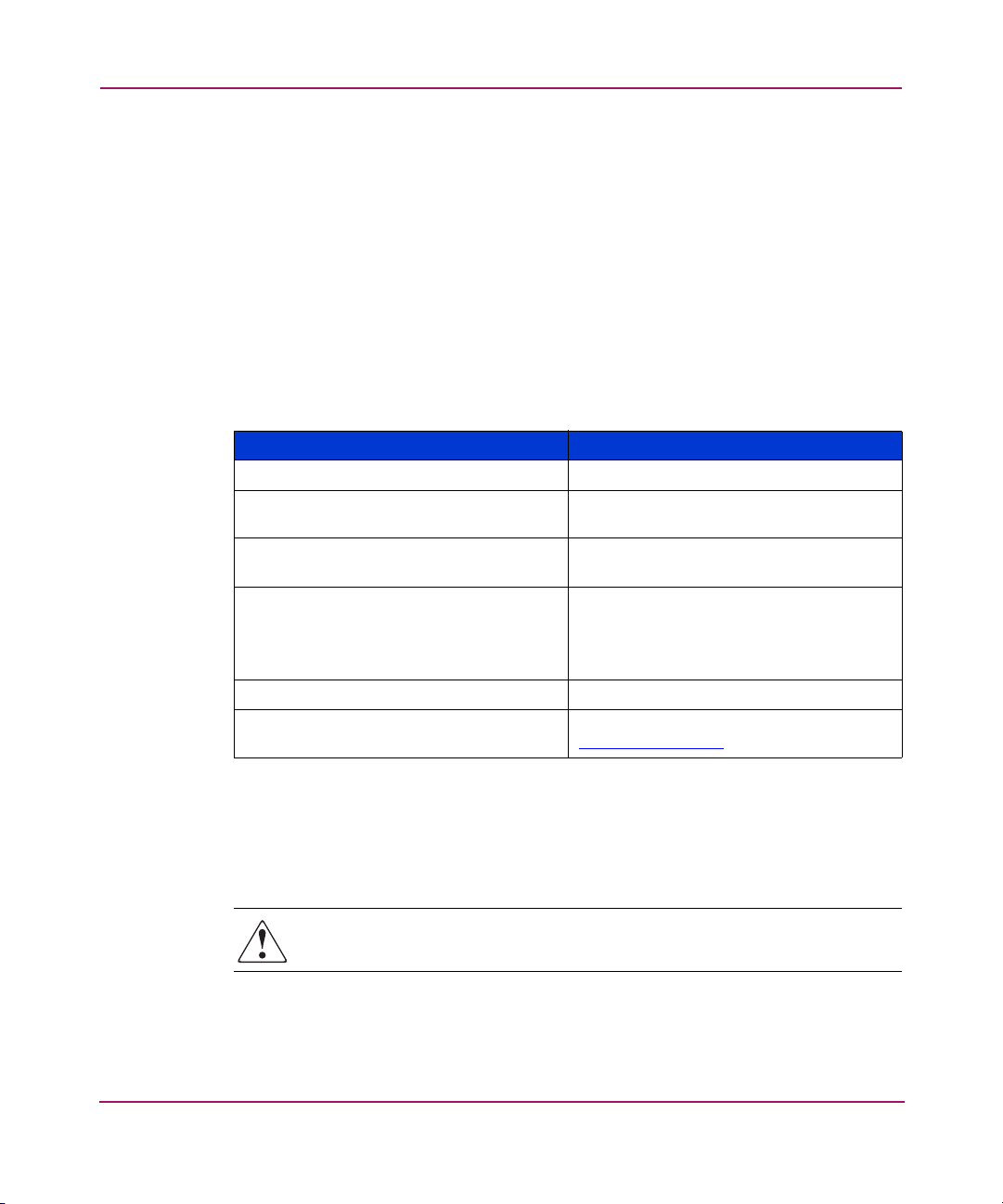
Table 1: Document Conventions
Cross-reference links Blue text: Figure 1
Key and field names, menu items,
buttons, and dialog box titles
File names, application names, and text
emphasis
User input, command and directory
names, and system responses (output
and messages)
Variables <monospace, italic font>
Website addresses Blue, underlined sans serif font text:
About this Guide
Element Convention
Bold
Italics
Monospace font
COMMAND NAMES are uppercase
monospace font unless they are case
sensitive
http://www.hp.com
Text Symbols
The following symbols may be found in the text of this guide. They have the
following meanings.
WARNING: Text set off in this manner indicates that failure to follow
directions in the warning could result in bodily harm or death.
AB232A PCI-X Host Bus Adapter Installation Guide
9
Page 10
About this Guide
Caution: Text set off in this manner indicates that failure to follow directions
could result in damage to equipment or data.
Note: Text set off in this manner presents commentary, sidelights, or interesting points
of information.
Equipment Symbols
The following equipment symbols may be found on hardware for which this guide
pertains. They have the following meanings.
Any enclosed surface or area of the equipment marked with these
symbols indicates the presence of electrical shock hazards. Enclosed
area contains no operator serviceable parts.
WARNING: To reduce the risk of personal injury from electrical shock
hazards, do not open this enclosure.
Any RJ-45 receptacle marked with these symbols indicates a network
interface connection.
WARNING: To reduce the risk of electrical shock, fire, or damage to
the equipment, do not plug telephone or telecommunications
connectors into this receptacle.
Any surface or area of the equipment marked with these symbols
indicates the presence of a hot surface or hot component. Contact with
this surface could result in injury.
WARNING: To reduce the risk of personal injury from a hot
component, allow the surface to cool before touching.
10 AB232A PCI-X Host Bus Adapter Installation Guide
Page 11
Getting Help
If you still have a question after reading this guide, contact an HP authorized
service provider or access our website
About this Guide
Power supplies or systems marked with these symbols indicate
the presence of multiple sources of power.
WARNING: To reduce the risk of personal injury from electrical
shock, remove all power cords to completely disconnect power
from the power supplies and systems.
Any product or assembly marked with these symbols indicates that the
component exceeds the recommended weight for one individual to
handle safely.
WARNING: To reduce the risk of personal injury or damage to the
equipment, observe local occupational health and safety requirements
and guidelines for manually handling material.
http://www.hp.com
.
HP Technical Support
Telephone numbers for worldwide technical support are listed on the HP website
http://www.hp.com/support/
Note: For continuous quality improvement, calls may be recorded or monitored.
Be sure to have the following information available before calling:
■ Technical support registration number (if applicable)
■ Product serial numbers
■ Product model names and numbers
■ Applicable error messages
■ Operating system type and revision level
■ Detailed, specific questions
AB232A PCI-X Host Bus Adapter Installation Guide
. From this website, select the country of origin.
11
Page 12

About this Guide
HP Storage Website
The HP website has the latest information on this product, as well as the latest
drivers. Access storage at
http://h18006.www1.hp.com/storage/s an in frastructure.html
From this website, select the appropriate product or solution.
HP Authorized Reseller
For the name of your nearest HP authorized reseller:
■ In the United States, call 1-800-345-1518
■ In Canada, call 1-800-263-5868
■ Elsewhere, see the HP website for locations and telephone numbers:
http://www.hp .com
.
.
12 AB232A PCI-X Host Bus Adapter Installation Guide
Page 13

Adapter Features
This introduction to the AB232A PCI-X Host Bus Adapter (HBA) includes:
■ Product Description, page 14
■ Performance Specifications, page 16
1
13AB232A PCI-X Host Bus Adapter Installation Guide
Page 14

Adapter Features
Product Description
The AB232A HBA has the following characteristics:
■ Robust suite of software supporting Windows Server 2003 Enterprise Edition,
64-bit version.
■ Optical small form factor (LC) interface LC Fibre connector.
■ Embedded optical shortwave laser, multi-mode Fibre Channel interface.
■ AB232A is designed using a single custom Application Specific Integrated
Circuit (ASIC). The custom ASIC implements a very high performance,
multiclass, multiprotocol Fibre Channel host adapter with a 64-bit PCI-X bus
connection.
■ 66/100/133MHz PCI-X 1.0a compatibility.
■ AB232A has a 266MIPs onboard processor, an embedded 1GB/2GB
SERDES, and a high performance unified QDR SRAM.
14 AB232A PCI-X Host Bus Adapter Installation Guide
Page 15
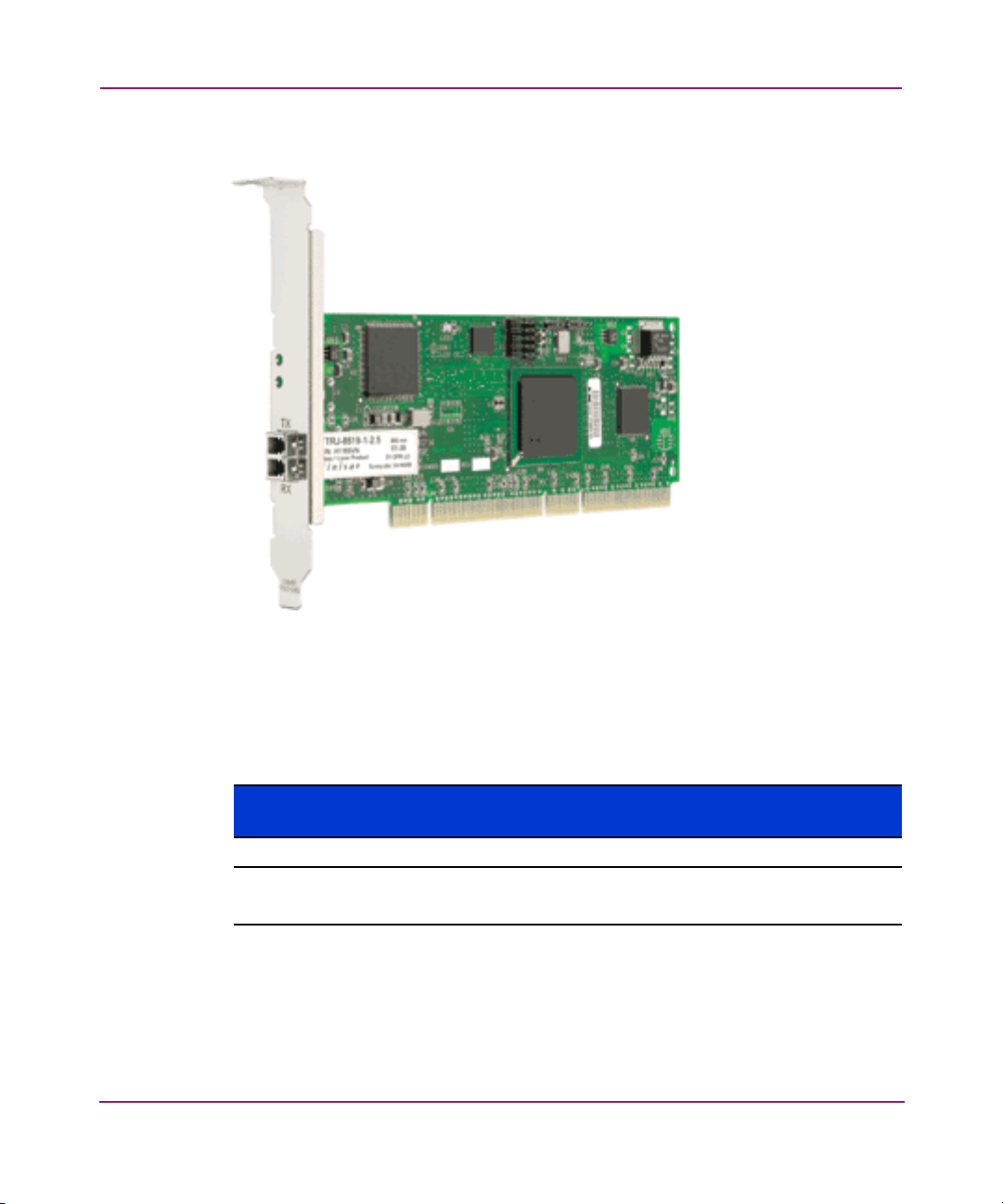
Figure 1 illustrates the AB232A HBA.
Adapter Features
Figure 1: AB232A HBA
■ Table 2 describes the AB232A HBA.
Table 2: AB232A HBA Diagram Description
Figure
Legend
1 Fibre Channel (LC) connectors.
2 POST LEDs indicators
Note: See Table 3, on page 22 for detailed descriptions.
Description
15AB232A PCI-X Host Bus Adapter Installation Guide
Page 16

Adapter Features
Performance Specifications
The AB232A HBA offers a highly integrated 2 Gbps Fibre Channel HBA for use
in Itanium servers based on the latest PCI-X expansion bus. The features of the
AB232A HBA provides the flexibility and broad interoperability needed for
complex, highly scalable SANs.
The AB232A HBA also features sophisticated hardware that provides superior
performance in SANs and provides best in class server CPU offload. This
exclusive hardware delivers low latency and high throughput in switched fabric,
arbitrated loop, and clustered environments. Support for fiber optic cabling is
provided through an embedded small form factor (LC) optical interface.
The AB232A HBA is both ANSI Fibre Channel and PCI Local Bus Compliant
and supports:
■ Full duplex 2 Gbps Fibre Channel that provides data transfers of up to 400
MBps.
■ Full fabric boot support to multiple LUNs.
■ FC-Tape (FC-2) devices.
■ Point-to-point, arbitrated-loop, and switch fabric FC connections.
■ Storage protocol.
■ Fibre Channel class 2 and 3.
■ Automatic speed negotiation and topology detection.
■ End-to-end parity protection for high data integrity.
Collectively, these characteristics create a high-performance Fibre Channel HBA.
16 AB232A PCI-X Host Bus Adapter Installation Guide
Page 17

Installation
This chapter provides step-by-step instructions for installing the AB232A HBA,
including:
■ Hardware Requirements
■ Recording Reference Numbers
■ Installing the HBA into a Computer
■ Verifying the Installation
■ Configuration Guidelines
This chapter also provides information on installation guidelines and supported
configurations for the operating systems.
2
Caution: The HBAs contain static-sensitive components. Make sure you
comply with Electrostatic Discharge (ESD) procedures described on page 59.
17AB232A PCI-X Host Bus Adapter Installation Guide
Page 18

Installation
Hardware Requirements
The system hardware requirements for installing the HBAs include:
■ AB232A HBA requires one open 64-bit/133 MHz PCI-X universal slot.
■ Multimode fiber optic cable with LC connector, used with shortwave lasers.
18 AB232A PCI-X Host Bus Adapter Installation Guide
Page 19

Recording Reference Numbers
Each HBA ships with a unique address identifier that is stored in flash memory.
Fibre Channel industry standards issue two unique identifiers: WorldWide Port
Name (WWPN) and Node Name (NN), each of which is derived from the HBA’s
IEEE address. Combined, the WWPN and NN create the WorldWide Name
(WWN) which is an 8-byte field that uniquely identifies an HBA on a FC circuit.
The WWN address and serial number are clearly marked on the HBA. Record the
addresses on the lines below for future reference.
Note: The WWN is a static identifier that cannot be changed.
IEEE address: __________________________________________________
Serial number: __________________________________________________
Installation
19AB232A PCI-X Host Bus Adapter Installation Guide
Page 20

Installation
Installing the HBA into a Computer
Use the following procedure for installing the HBA into a computer.
Caution: Be sure to observe the ESD precautions described on page 59 for
this procedure.
1. Make sure the computer is powered off.
2. Remove the screws on the computer cover, and then remove the cover.
3. Wearing a static wrist strap, remove the blank panel from an empty 64-bit
PCI-X bus slot.
Compare the removed panel to the bracket on the HBA. Follow steps 4–7 to
change the bracket if the brackets are different sizes.
Note: The HBAs come with a standard PCI bracket installed. The low-profile mounting
bracket is shorter than the standard bracket; approximately 7.9 cm (3.11 in.)
compared to 12.06 cm (4.75 in.) long.
4. Remove the mounting bracket screws from the top of the HBA.
5. Remove the bracket and store it for future use.
6. Align the new mounting bracket tabs with the holes in the HBA.
Note: Be careful not to push the bracket past the transceiver housing's grounding
tabs.
7. Replace the screws that attach the HBA to the bracket.
8. Insert the HBA into the empty PCI-X bus slot; press firmly until it is seated
securely.
9. Secure the HBA mounting bracket to the computer panel with the panel
screws.
10. Replace the computer cover and secure it using the previously removed
screws.
20 AB232A PCI-X Host Bus Adapter Installation Guide
Page 21

Installation
11. Attach media:
a. Connect the fiber optic cable to the LC connector on the HBA.
b. Connect the other end of the cable to the Fibre Channel device.
Note: The HBAs do not allow normal data transmission on an optical link unless the
link is connected to a similar or compatible laser product. That is, both products are
multimode to multimode.
21AB232A PCI-X Host Bus Adapter Installation Guide
Page 22

Installation
Verifying the Installation
To verify the HBA is properly installed and is operating:
1. Turn on the computer.
2. At power up, observe the POST LED indicators on the HBA. The position of
the POST LED indicators is defined in page 15 on page 15, and Table 2 on
page 22 of this guide. The green LED indicates power functions and the
amber LED signifies port activity. The amber LED blinks at all times during
normal operation.
Tabl e 3 lists normal LED indications.
Table 3: Normal POST LED Indicators
Amber LED (L1) Green LED (L2) State
Off Off Wake-up failure (dead board)
On Off POST failure (dead board)
Slow blink (1 Hz) Off Wake-up failure (dead board)
Fast blink (4 Hz) Off Failure in POST (dead board)
Flashing (irregular) Off POST processing in progress
Off On Failure while functioning
On On Failure while functioning
Slow blink (1 Hz) On Normal—1 Gb link rate
Fast blink (4 Hz) On Normal—2 Gb link rate
Off Blink (1 Hz) Normal—link down or not yet
started
22 AB232A PCI-X Host Bus Adapter Installation Guide
Page 23

Configuration Guidelines
The software for loading the driver also contains the default registry parameter
settings that are loaded as part of the driver installation. Consult the following
sources for any restriction and for information on supported configurations
specific to your operating system and topology.
■ Release Notes
Installation
■ HP Website at
http://www.hp.com/country/us/eng/su pport.html
.
23AB232A PCI-X Host Bus Adapter Installation Guide
Page 24

Installation
24 AB232A PCI-X Host Bus Adapter Installation Guide
Page 25

Installing the SCSI Miniport Driver
This chapter contains step-by-step instructions for installing the SCSI Miniport
driver.
System managers must be familiar with the Windows Server 2003 operating
system under which the PCI-X-to-Fibre Channel HBA is to operate. System
managers must also have access to standard system documentation.
HBA files are updated periodically. You can download the latest versions of the
HBA driver kits from the HP website at
http://h18000.www1.hp.com/storage/saninfrastructure.html
Note: This chapter describes the steps for installing the device driver and for
accessing Fibre Channel storage devices. For other configuration changes, see Modify
Diagnostic Driver Parameters in the Windows Registry, on page 40.
3
.
25AB232A PCI-X Host Bus Adapter Installation Guide
Page 26

Installing the SCSI Miniport Driver
Device Driver Installation
This section describes the instructions for installing the Windows SCSI Miniport
driver.
System Requirements
Ensure that your system meets these minimum requirements:
■ Installed HBA
■ StorageWorks Fibre Channel Storage subsystem (interconnect device and
storage device)
Installing or Upgrading a New Driver
The AB232A HBA is a plug-and-play device that is detected by Windows
operating systems. Perform the following steps to add or update the Windows
driver to a previously installed Windows system:
1. Install the HBA as described in Chapter 2 on page 17.
2. Restart or turn on the computer.
3. Browse to the the driver kit on the Smart Setup CD-ROM (or one you
downloaded from the website if it is more recent).
4. Double-click cp00xxxx.exe.
Note: Refer to the following website for the information about this Smart Component’s
final version number:
http://h18000.www1.hp.com/storage/saninfrastructure.htm
l.
5. Follow the installation wizard instructions.
6. When the installation completes, you must reboot.
7. Repeat step 1 through step 6 for any additional HBAs. Make sure to reboot
after installing the driver for the last HBA.
26 AB232A PCI-X Host Bus Adapter Installation Guide
Page 27

Installing the LightPulse Utility
The LightPulse Utility, LpUtilNt (described in Diagnostic and Configuration
Utilities, on page 37) does not automatically load. HP recommends that after
loading the HBA driver, you install LpUtilNt as follows:
1. Browse to the LighPulse folder on the Smart Setup CD-ROM (or to one
downloaded from the web site if it is more recent).
2. Double-click cp00xxxx.exe.
Note: Refer to the following website for the information about this Smart Component’s
final version number:
http://h18000.www1.hp.com/storage/saninfrastructure.htm
3. Follow the installation wizard instructions.
4. After the installation completes, you can start the LightPulse Utility by
choosing Start > Programs > LpUtilNt.
Installing the SCSI Miniport Driver
l.
27AB232A PCI-X Host Bus Adapter Installation Guide
Page 28

Installing the SCSI Miniport Driver
28 AB232A PCI-X Host Bus Adapter Installation Guide
Page 29

Troubleshooting
The Power-On Self Test (POST) and the Windows Event Viewer are utilities you
can use for troubleshooting the HBA. This chapter explains the use of these
utilities in the event of an HBA problem.
4
29AB232A PCI-X Host Bus Adapter Installation Guide
Page 30

Troubleshooting
POST Conditions and Results
Tabl e 4 lists the HBA LED states with descriptions of each.The position of the
POST LED indicators is defined in Figure 1 on page 15, and Tabl e 3 on page 22
of this guide.
If the LEDs indicate a failure during POST:
1. Make sure that the HBA is seated firmly in the PCI slot.
2. Verify that the fiber cable connection to the HBA is secure.
Table 4: Normal POST LED Indicators
Amber LED (L1) Green LED (L2) State
Off Off Wake-up failure (dead board)
On Off POST failure (dead board)
Slow blink (1 Hz) Off Wake-up failure (dead board)
Fast blink (4 Hz) Off Failure in POST (dead board)
Flashing (irregular) Off POST processing in progress
Off On Failure while functioning
On On Failure while functioning
Slow blink (1 Hz) On Normal—1 Gb link rate
Fast blink (4 Hz) On Normal—2 Gb link rate
Off Blink (1 Hz) Normal—link down or not yet
started
30 AB232A PCI-X Host Bus Adapter Installation Guide
Page 31

Using The Event Viewer
The Windows SCSI driver verifies the condition of the HBA POST. If there is a
failure or a suspected failure, an error log entry is issued to the Windows Event
log.
Following is the procedure for viewing the event log.
From the Main menu:
1. Double-click or choose the Administrative Tools program group.
2. Double-click or choose the Event Viewer.
3. Specify LPXNDS.
Note: You can find the source name in the SCSI device’s Disk Manager.
4. Double-click any event with the source name.
5. Change the data view from Bytes (default) to Word s.
6. Examine the entry at offset 0x10: if the low byte = En, match the low byte
with the error found in Tabl e 5 on page 32, SCSI Port Error Log. Table 6 on
page 34, and Table 7 on page 35 list CmdStat values and Parameter error
values.
Troubleshooting
31AB232A PCI-X Host Bus Adapter Installation Guide
Page 32

Troubleshooting
Windows Miniport Event Log Codes
The Windows Miniport driver logs events and errors in the Windows Event log.
Serious errors are always logged. Informational events are only logged if the
registry parameter LogError=1 is used.
All Miniport logged events are issued with an Event ID of 11 (INTERNAL
ADAPTER ERROR) but do not necessarily indicate an HBA error occurred. Byte
offset 0x10 of the event is the driver event code. Byte offsets 0x11 to 0x13 contain
event-specific information.
Tabl e 5 describes the SCSI port error log codes.
Table 5: SCSI Port Error Log Codes
0x10
Offset
0xD0 SNS_REQ (XMIT_SEQ
failed)
0xD1 SNS_RSP (RCV_SEQ
failed)
0xD3 RCV_ELS_REQ failed 0x11 = cmdstat, 12 = parm err
0xD4 XMT_ELS_REQ failed 0x11 = cmdstat, 12 = parm err
0xD5 Too many targets found
(160+)
0xD6 SNS request time-out 0x11 to 13 = no additional information
0xD7 Mailbox interrupt time-out 0x11 = mailbox word 0
0xD8 TPRLO requested when
busy
0xD9 Link down time-out
occurred
0xDA Hard link down time-out
occurred
0xE1 Error interrupt occurred Status register bytes 1–3 in event
0xE2 Mailbox cmd time-out 0x11 = command
Explanation 0x11 to 0x13 Further Information
0x11 = cmdstat, 12 = parm err
0x11 = cmdstat, 12 = parm err
0x11 to 13 = D_DID that didn’t fit
0x11 = local req. state, 12 =
discstate, 13 = mailbox word 0
0x11 = local req. state, 12 =
discstate, 13 = mailbox word 0
0x11 = local req. state, 12 =
discstate, 13 = mailbox word 0
11–13. E1 error indicates an HBA
hardware failure, return HBA for
repair.
32 AB232A PCI-X Host Bus Adapter Installation Guide
Page 33

Troubleshooting
Table 5: SCSI Port Error Log Codes (Continued)
0x10
Offset
Explanation 0x11 to 0x13 Further Information
0xE3 Mailbox rsp err 0x11 = command, 12–13 =
mbxstatus
0xE4 HBA not ready after init Status register bytes 1–3 in event
11–13
0xE5 Requested loop but link =
PT–PT
0xE6 Mailbox int. but cmd not
0x11 = MB cmd, 12–13 = mbxstatus
complete
0xE7 SRB already queued to ring
0xE8 RESTART failed
0xE9 PORT BYPASS (LPB)
received
0xEB Unknown IOCB cmd rsp 0x11 = 15:8 = cmd field
0xEC Uncached extension alloc.
error
0xED Link down @ boot time
(30 sec)
0xEF Too many interrupts at
initial boot
0xF1 LinkUp error; LP8 down,
driver up
0xF2 LinkUp w/ illegal or corrupt
RPI
0xF3 DeQueue
0x11 = parameter field, 12 = IOCB
cmd
0x11 = parameter field, 12 = IOCB
cmd
0x11 = caller ID
ring->iotcmd.head
0xF4 HBA reset 0x11 = coded reason for reset:
Bit 0 = IOCB requeue; bit 1 = readla
retry
Bit 2 = initlink retry; bit 3 = rstbus retry
Bit 4 = mailbox time-out
0xF5 PCP_IXXX_CR IOCB rsp
err
0x11 = cmdstat, 12 = parm err, 13 =
ALPA
33AB232A PCI-X Host Bus Adapter Installation Guide
Page 34

Troubleshooting
Table 5: SCSI Port Error Log Codes (Continued)
0x10
Offset
0xF6 PCP_IXXX_CR IOCB rsp
err
Explanation 0x11 to 0x13 Further Information
0x11 = cmdstat, 12 = parm err, 13 =
ALPA
0xF7 Ring hd !=0 &&
pendingsrb!=NULL
0xF8 Invalid FCP_RSP 0x11 = pcpcntrl, 12 = scsisat, 13 =
len
0xF9 Two consec. time-outs,
issue LIP
0xFA START_IO error 0x11 = errtype, 12 = srbstat, 13 =
linkup
0xFB ELS_REQ_CR IOCB rsp err 0x11 = cmdstat, 12 = parm err, 13 =
ALPA
0xFC ELS_REQ_CR IOCB rsp err 0x11 = cmdstat, 12 = parm err, 13 =
ALPA
0xFE FLOGI failed 0x11 = cmdstat, 12 = parm err
0xFF SNS_PLOGI failed 0x11 = cmdstat, 12 = parm err
Table 6: CmdStat Values
0x11
Offset
Explanation Further Information
0x1 IOSTAT_FCP_RSP_ERR
0x2 IOSTAT_REMOTE_STOP Remote sent an ABTS
0x3 IOSTAT_LOCAL_REJECT Parameter field contains
additional information
0x4 IOSTAT_NPORT_RJT
0x5 IOSTAT_FABRIC_RJT
0x6 IOSTAT_NPORT_BSY
0x7 IOSTAT_FBRIC_BSY
34 AB232A PCI-X Host Bus Adapter Installation Guide
Page 35

Troubleshooting
Table 6: CmdStat Values (Continued)
0x8 IOSTAT_INTERMED_RSP
0x9 IOSTAT_LS_RJT Remote sent LS_RJT
0xA IOSTAT_BA_RJT Remote sent BA_RJT
Table 7: Parameter Error Values Valid only when CmdStat=0x3
0x12
Offset
Explanation Further Information
0x00 IOERR_SUCCESS
0x01 IOERR_MISSING_CONTINUE
0x02 IOERR_SEQUENCE_TIMEOUT Possible bad cable/link noise
0x03 IOERR_INTERNAL_ERROR
0x04 IOERR_INVALID_RPI Remote port login data invalid
0x05 IOERR_NO_XRI
0x06 IOERR_ILLEGAL_COMMAND
0x07 IOERR_XCHG_DROPPED
0x08 IOERR_ILLEGAL_FIELD
0x09 IOERR_BAC_CONTINUE
0x0A IOERR_TOO_MANY_BUFFERS
0x0B IOERR_RCV_BUFFER_WAITING
0x0C IOERR_NO_CONNECTION
0x0D IOERR_TX_DMA_FAILED
0x0E IOERR_RX_DMA_FAILED
0x0F IOERR_ILLEGAL_FRAME Possible bad cable/link noise
0x10 IOERR_EXTRA_DATA
0x11 IOERR_NO_RESOURCES
0x12 IOERR_RESERVED
0x13 IOERR_ILLEGAL_LENGTH
0x14 IOERR_UNSUPPORTED_
FEATURE
0x15 IOERR_ABORT_IN_PROGRESS
35AB232A PCI-X Host Bus Adapter Installation Guide
Page 36

Troubleshooting
Table 7: Parameter Error Values Valid only when CmdStat=0x3 (Continued)
0x12
Offset
Explanation Further Information
0x16 IOERR_ABORT_REQUESTED
0x17 IOERR_RECEIVE_BUFFER_
TIMEOUT
0x18 IOERR_LOOP_OPEN_FAILURE FC_AL target not responding.
Received our own transmitted
frame back. Port may be
bypassed by a hub.
0x19 IOERR_RING_RESET
0x1A IOERR_LINK_DOWN
0x1B IOERR_CORRUPTED_DATA
0x1C IOERR_CORRUPTED_RPI
0x1D IOERR_OUT_OF_ORDER Possible bad cable/link noise
0x1E IOERR_OUT_OF_ORDER_ACK
0x1F IOERR_DUPLICATE_FRAME
0x20 IOERR_INVALID_ACK
0x21 IOERR_BAD_40BIT_ADDRESS
0x22 IOERR_RESERVED
0x23 IOERR_RESERVED
0x24 IOERR_RESERVED
0x25 IOERR_ABORT_MULTI_
REQUESTED
0x26 IOERR_RESERVED
0x27 IOERR_RESERVED
0x28 IOERR_LINK_BUFFER_
SHORTAGE
0x29 IOERR_RCV_XRIBUF_WAITING
36 AB232A PCI-X Host Bus Adapter Installation Guide
Page 37

Diagnostic and Configuration Utilities
This chapter contains instructions for using the LightPulse Utility, LpUtilNt, a
Windows-based graphical user interface. Use this utility to update firmware,
BIOS, view registry parameters, perform persistent binding operations on selected
targets, and obtain specific information about all HBAs installed in the server.
5
37AB232A PCI-X Host Bus Adapter Installation Guide
Page 38

Diagnostic and Configuration Utilities
Using LightPulse Utility
The LightPulse Utility (LpUtilNt) is an HBA utility that lets you:
■ View HBA parameters
■ Modify driver parameters in the Windows registry
The Original Equipment Manufacturer (OEM) setup file provided in the software
kit sets these parameters. The Fibre Channel setup file that comes with the
platform kit, modifies these parameters. The resulting parameter settings provide
the optimal setting for your configurations.
Note the following:
■ You must install and connect the SCSI Miniport driver to at least one drive
before LightPulse Utilitycan operate properly. You can alternately set the
registry parameter Simulate Device=1.
■ LightPulse Utility does not load automatically on Windows Server 2003
systems. HP recommends that you install the LightPulse utility after installing
the HBA drivers as described in the section Installing the LightPulse Utility
on page 27.
View HBA Parameters
From the LightPulse Utility Main menu screen:
1. Choose an HBA.
2. On the menu bar, click on an HBA or pull down the category list.
3. Choose an option to view HBA parameters.
Each of the following options displays a different group of HBA parameters:
■ Adapter Revision Levels—View information about the chipset and
firmware revision levels of the selected HBA.
■ Firmware Maintenance—View detailed information about the firmware
in the flash ROM of the selected host adapter. Update host adapter
firmware and boot code, manage existing firmware, and enable or disable
the BootBIOS bootup message.
■ Loop Map—View a list of the members of the selected HBA loop map.
■ PCI Registers—View the values of the PCI configuration registers for the
selected HBA.
38 AB232A PCI-X Host Bus Adapter Installation Guide
Page 39

Diagnostic and Configuration Utilities
■ Configuration Data—View information about the data in each of the
configuration regions in the flash ROM of the selected HBA.
■ Drive Parameters—View information about device driver parameters that
are maintained in the Windows/NT registry.
■ Persistent Binding—View and manage persistent binding for the adapter,
and LUN mapping and masking for devices in your SAN.
■ Link Statistics—View statistics about the arbitrated loop of the selected
HBA.
■ Status and Counters—View status and counters for bytes, frames,
sequences, exchanges, and so on.
4. Expand the category list and choose Firmware Maintenance.
5. Click Download.
6. Locate the new upgrade file.
7. Click Open.
Note: The new software is transferred to the HBA.
8. Expand the category list and choose Adapter Revision Levels.
9. Verify that the new firmware revision is shown.
39AB232A PCI-X Host Bus Adapter Installation Guide
Page 40

Diagnostic and Configuration Utilities
Modify Diagnostic Driver Parameters in the Windows Registry
This screen provides information about device driver parameters that are
maintained in the Windows registry and allows you to modify those values.
Caution: Do not modify the registry parameters unless specifically instructed
to do so by support personnel. Modifying registry parameters can result in an
unstable SAN.
The data display lists all available device driver parameters, along with the
current, minimum, maximum, and default values. Parameters that have their value
specified in the system registry are denoted with either a G or an L in the left-most
column of the screen. The G indicates that the value is set in the global registry
entry, which applies to all HBAs that do not have a local registry entry. The L
indicates that the value is set in a registry entry specific to the selected HBA,
which overrides the value settings in the global entry.
Modify the Driver Parameters
From the LightPulse Utility Main menu screen:
1. Choose the desired HBA.
2. Expand the category list and choose Driver Parameters.
3. Double-click a Parameter Name.
4. Enter the desired value in the New Value field.
5. Choose the Permanent or Global checkbox:
■ Choose Permanent to cause the new value to be written to the system
registry. If Permanent is not selected, the parameter reverts to its default
value when the driver is reset.
■ Choose Global to change the global registry entry. Otherwise, the change
is made to the HBA-specific registry entry.
40 AB232A PCI-X Host Bus Adapter Installation Guide
Page 41

Diagnostic and Configuration Utilities
Tabl e 8 lists the current parameters that you can set.
Table 8: Drive Parameters
Parameter Description
AbortStatus = 0xn Values from 0x00 – 0xFF. Controls NT SRB error status
for general Abort conditions.
Default = SRB_STATUS_BUS_RESET (0x0E) which will
not cause the current NT class driver to throttle down I/O
performance after four of these errors have been
received (on a per-LUN basis).
ALTOV = n Values are in milliseconds from 1 to 15. Default = 15.
ARBTOV = n Values are milliseconds from 500 to 10000. Default =
1000. Represents FC_AL arbitration time-out prior to LIP.
Class = n Values from 0 to 2. Default = 2. Controls which Fibre
Channel Class will be used: 0 = Class 1, 1 = Class 2, 2 =
Class 3.
EDTOV = n Values are in milliseconds from 500 to 10000. Default =
1000. Represents error detect time-out value prior to LIP.
EnableDPC = n Values 0 or 1. Default = 0. 0 = process I/O completion at
interrupt level, 1 = process at DPC level.
FrameSizeMSB = n Values from 1 – 8. Default = 8. Controls the upper byte of
the receive FrameSize if issued in PLOGI. This allows the
FrameSize be constrained on 256 byte increments from
256 (1) – 2048 (8).
HardALPA = 0xn Values from 0x01 – 0xEF. Default = 0x01 allows the HBA
use a hard assigned loop address. NOTE: Only valid
ALPAs can be used (see Tabl e 9 on page 44).
LinkTimeOut = n Values are in seconds from 1 – 500. Default = 60.
Controls the time-out at which link no longer busy with
requests but issues SELECTION_TIMEOUT error status.
LogErrors = n Values 0 or 1. Default = 0. 0 = don’t log general
HBA/drive errors. 1 = use Event Log to log general
errors.
NodeTimeOut = n Values are in seconds from 1–255.
Default = 10. Controls the time-out at which a formerly
logged-in node will issue SELECTION_TIMEOUT error
status to an I/O request.
41AB232A PCI-X Host Bus Adapter Installation Guide
Page 42

Diagnostic and Configuration Utilities
Table 8: Drive Parameters (Continued)
Parameter Description
QueueDepth = n Values from 1–64 (decimal). Default = 64. Requests per
QueueTarget = n Values 0 or 1 (decimal). Default = 0. 0 = QueueDepth
RATOV = n Values are in seconds from 2 to 120. Default = 2. This
ReadCheck = n Values 0 or 1. Default = 1. 0 = do not enable byte
ResetFF = n Values 0 or 1. Default = 1. 0 = ResetBus translates to LIP
ResetTPRLO = n Values 0 or 1. Default = 1. 0 = ResetBus translates to LIP
RetryInterval = n Values are in seconds from 2-255. Default = 45. Used for
RetryloTimeOut = n Values 0 or 1. Default = 1. 1 = allows HBA to time-out I/O
RTTOV = n Values are in milliseconds from 100 to 511. Default =
ScanDown = n Values 0 or 1. Default = 0. 0 = Lowest AL_PA = Lowest
LUN/Target (see Queue Target parameter).
applies on a per LUN basis: 1 = QueueDepth applies on
a Target basis.
value is the ELS request time-out.
counting for read operations. 1 = enable byte counting. If
bytes counted are less than requested transfer count,
issue underrun.
(F7). 1 = ResetBus translates to LIP (FF). Used for
WolfPack to force reservations to be freed when
ResetBus issued. Only meaningful for FC_AL topology
and Seagate native FC hard drives.
(). 1 = ResetBus translates to ThirdPartyProcessLogout +
LIP (). Used for WolfPack to force reservations to be
freed when ResetBus is issued.
time-out interval if RetryloTimeOut = 1. Must be shorter
than Class driver TimeOutInterval.
prior to port driver’s time-out that causes a LIP/Link
Reset.
256. Represents time-out between phases of Off-line to
On-line protocol.
physical disk (ascending AL_PA order). 1 = Highest
AL_PA = Lowest Physical Disk (ascending SEL_ID
order).
42 AB232A PCI-X Host Bus Adapter Installation Guide
Page 43

Diagnostic and Configuration Utilities
Table 8: Drive Parameters (Continued)
Parameter Description
SilFlags = n Values from 0-2. Default = 0. Controls which driver
interface to use. 0 = automode; attempt SLI-2 first. If that
fails, uses SLI-1. 1 = always use SLI-1. 2 = always use
SLI-2.
SimulateDevice = n Values 0 or 1. Default = 0. 0 = do not create a “dummy”
disk device. 1 = create a dummy disk to force the driver
to load even if no disk devices are present at boot time.
SnsALL = n Values 0 or 1. Default = 1. Controls which N_Ports are
queried from the NameServer. 0 = SCSI FCP only. 1 = All
N_Ports.
Topology = n Value 0 through 3. Default = 2. 0 = FC_AL (loop), 1 =
PT-PT Fabric, 2=FC-AL first, then attempt PT-PT,
3=PT-PT first, then attempt FC-AL. When set to 1,
FLOGI, SCR/RSCN and NameServer queries are
employed.
TrafficCop = n Values 0 or 1. Default = 0. 1 = enable FC-AL loop master
to run unfair and break potential arbitration problems by
sending frames to itself. 0 = run fair all the time.
43AB232A PCI-X Host Bus Adapter Installation Guide
Page 44

Diagnostic and Configuration Utilities
Tabl e 9 lists the Arbitrated Loop Physical Addresses (AL-PA) you can set.
Table 9: AL-PA Values
0x01 0x02 0x04 0x08 0x0F 0x10 0x17 0x18 0x1B
0x1D 0x1E 0x1F 0x23 0x25 0x26 0x27 0x29 0x2A
0x2B 0x2C 0x2D 0x2E 0x31 0x32 0x33 0x34 0x35
0x36 0x39 0x3A 0x3C 0x43 0x45 0x46 0x47 0x49
0x4A 0x4b 0x4C 0x4D 0x4D 0x51 0x52 0x53 0x54
0x55 0x56 0x59 0x5A 0x5C 0x63 0x65 0x66 0x67
0x69 0x6A 0x6B 0x6C 0x6D 0x6E 0x71 0x72 0x73
0x74 0x75 0x75 0x79 0x7A 0x7C 0x80 0x81 0x82
0x84 0x88 0x8F 0x90 0x97 0x98 0x9B 0x9D 0x9E
0x9F 0xA3 0xA5 0xA6 0xA7 0xA9 0xAA 0xAB 0xAC
0xAD 0xAE 0xB1 0xB2 0xB3 0xB4 0xB5 0xB6 0xB9
0xBA 0xBC 0xC3 0xC5 0xC6 0xC7 0xC9 0xCA 0xCB
0xCC 0xCD 0xCE 0xD1 0xD2 0xD3 0xD4 0xD5 0xD5
0xD9 0xDA 0xDC 0xE0 0xE1 0xE2 0xE4 0xE8 0xEF
Set Up Persistent Binding
The persistent binding feature allows you to control the devices that are to be
presented to the system.
The Miniport driver detects all devices attached to the HBAs. Global
automapping assigns a binding type, target ID, SCSI bus, and SCSI ID to the
device. The binding type, SCSI bus, and SCSI ID may change when the system is
rebooted. When persistent binding is applied to one of these targets, the binding
type, SCSI bus, and SCSI ID remain the same, whether the system is rebooted or
whether Global Automap All Targets is subsequently disabled (enabled by
default).
The binding information is permanent because it is stored in the Windows
registry. The driver refers to the binding information at bootup.
44 AB232A PCI-X Host Bus Adapter Installation Guide
Page 45

Persistent binding permanently maps a device to the following:
■ Binding type World Wide Port Name (WWPN), World Wide Node Name
(WWNN), or a Destination Identifier (D_ID)
■ SCSI bus
■ SCSI ID
Prerequisites
■ Installed Miniport driver with the adjunct driver
■ Installed LightPulse Utility
■ Global Automap All Targets is enabled. Global Automap All Targets is
enabled or disabled from the Global Automap window
Setting Up Persistent Binding
From the LightPulse Utility Main menu screen:
1. Choose the desired HBA.
2. Expand the category list and choose Persistent Binding.
3. Click on a target and click Add. The Add Binding window displays, as
shown in Figure 2.
Diagnostic and Configuration Utilities
Figure 2: Add Binding window
4. Click the target to be bound from the Unbound Targets list.
5. If required, change the Bind Type for the target.
6. If required, change the SCSI Bus and SCSI ID values.
7. Click OK. The letters PB display next to the target row.
45AB232A PCI-X Host Bus Adapter Installation Guide
Page 46

Diagnostic and Configuration Utilities
Global Automap and Unmasking Overview
Global Automap All Targets defaults to enabled, to allow the driver to detect all
Fibre Channel devices attached to the HBAs. If Global Automap All Targets is
disabled, the driver detects Fibre Channel devices attached to the HBA, and does
not pass them to the operating system unless they are already persistently bound.
Global Automap All LUNs defaults to enabled and assigns an operating system
LUN ID to a Fibre Channel LUN ID for all LUNs behind the targets in your SAN.
LUN mapping can also be enabled and disabled at the target level. Global
automapping of LUNs is different from persistent binding. Global LUN
automapping does not concern itself with the SCSI ID or SCSI Bus. This is
because the global LUN mapping stays the same for the target when the system is
rebooted.
Globally Unmask All LUNs defaults to enabled, to allow the operating system
to see all LUNS behind targets. If Globally Unmask All LUNS is set to disabled
and you want the operating system to see all LUNS behind a specific target, you
must set unmasking at the target level.
Prerequisites
■ Installed SCSI Miniport driver
■ Installed LightPulse Utility
■ A target device with LUNs that have been properly configured
■ LUN Automap enabled and LUN Unmasking disabled on the LUN Mapping
window:
— If LUN Automap is enabled for the target, you can map each LUN
individually.
— Unless LUNs were previously mapped, if LUN Automap is disabled for
the target, no LUNs will be mapped when you reboot the system.
— If LUN Unmasking is disabled for the target, the HBA can see all LUNS
behind a specific target.
46 AB232A PCI-X Host Bus Adapter Installation Guide
Page 47

Mapping and Masking LUNs
From the LightPulse Utility Main menu screen:
1. Choose the desired HBA.
2. Expand the category list and choose Persistent Binding.
3. Click on a target. The Lunmap button becomes active.
4. Click Lunmap. The Lunmap window displays, as shown in Figure 3:
Diagnostic and Configuration Utilities
Figure 3: Lunmap window
Test Host Bus Adapters
Choose this option to run host-based internal and external loopback tests on the
HBAs.
From the LightPulse Utility Main menu screen:
1. Choose Test Host Bus Adapters.
2. Enable or disable the external loopback tests:
a. Enable the external loopback tests by choosing 1=Y. The default is
disabled, 0=No. Internal BIU PCI loopback and other loopback tests are
run automatically.
b. Choose 0=No if you do not have an external loopback connector.
47AB232A PCI-X Host Bus Adapter Installation Guide
Page 48

Diagnostic and Configuration Utilities
Note: Testing the HBA while it is connected to an arbitrated loop is not recommended.
Modify Test Options
Use this option to specify the number of passes on one or more of these tests: PCI
loopback, internal loopback, external Loopback, or all three.
From the LightPulse Utility Main menu screen:
1. Choose Te st .
2. Choose the following data for the PCI loopback, Internal loopback, External
Loopback tests:
a. The number of passes. The default is 0x50. 0=infinity
b. The action to take upon encountering errors. Choose one of the following:
— 0 = stop (default)
—1 = repeat
—2 = ignore
Restart Host Bus Adapters
Choose this option to reset the HBA. When a restart HBA occurs, the HBA
performs POST testing and reloads functional firmware.
Input/Output
Choose this option to open or close input and output files. The contents of the
input file are interpreted and executed by the program. The output file contains a
log of all messages. Note that nesting of input files is not supported.
Maintenance
Choose this option to update firmware or non-volatile parameters in the flash
ROM. This option also displays program images (load list) stored in the HBA
memory. You must reboot the HBA for the new firmware to take effect.
48 AB232A PCI-X Host Bus Adapter Installation Guide
Page 49

Show Host Bus Adapter Info
Choose this option to display HBA data in these areas:
■ BIU PCI Configuration Parameters
■ HBA Info and Status
■ Adapter Revisions
■ Display Configuration Data
■ Service Parameters
■ Status/Counters Info
■ Link Status
■ Link Attention
Quit the LightPulse Utility
Choose this option to exit the program. A warning message indicates if any errors
were encountered during the session.
Diagnostic and Configuration Utilities
49AB232A PCI-X Host Bus Adapter Installation Guide
Page 50

Diagnostic and Configuration Utilities
50 AB232A PCI-X Host Bus Adapter Installation Guide
Page 51

Regulatory Compliance Notices
This appendix covers the following topics:
■ Federal Communications Commission Notice, page 52
■ Canadian Notice (Avis Canadien), page 54
■ European Union Notice, page 55
■ Japanese Notice, page 56
■ Laser Safety, page 58
A
51AB232A PCI-X Host Bus Adapter Installation Guide
Page 52

Regulatory Compliance Notices
Federal Communications Commission Notice
Part 15 of the Federal Communications Commission (FCC) Rules and
Regulations has established Radio Frequency (RF) emission limits to provide an
interference-free radio frequency spectrum. Many electronic devices, including
computers, generate RF energy incidental to their intended function and are,
therefore, covered by these rules. These rules place computers and related
peripheral devices into two classes, A and B, depending upon their intended
installation. Class A devices are those that may reasonably be expected to be
installed in a business or commercial environment. Class B devices are those that
may reasonably be expected to be installed in a residential environment (for
example, personal computers). The FCC requires devices in both classes to bear a
label indicating the interference potential of the device as well as additional
operating instructions for the user.
The rating label on the device shows the classification (A or B) of the equipment.
Class B devices have an FCC logo or FCC ID on the label. Class A devices do not
have an FCC logo or ID on the label. After the class of the device is determined,
refer to the corresponding statement in the sections below.
Class A Equipment
This equipment has been tested and found to comply with the limits for a Class A
digital device, pursuant to Part 15 of the FCC Rules. These limits are designed to
provide reasonable protection against harmful interference when the equipment is
operated in a commercial environment. This equipment generates, uses, and can
radiate radio frequency energy and, if not installed and used in accordance with
the instructions, may cause harmful interference to radio communications.
Operation of this equipment in a residential area is likely to cause harmful
interference, in which case the user will be required to correct the interference at
personal expense.
Declaration of Conformity for Products Marked with FCC Logo—United
States Only
This device has been tested and found to comply with the limits for a Class A
digital device, pursuant to Part 15 of the FCC Rules. These limits are designed to
provide reasonable protection against harmful interference when the equipment is
operated in a commercial environment. This equipment generates, uses and can
radiate radio frequency energy and, if not installed and used in accordance with
the instruction manual, may cause harmful interference to radio communications.
52 AB232A PCI-X Host Bus Adapter Installation Guide
Page 53

Operation of this equipment in a residential area is likely to cause harmful
interference, in which case users will be required to correct the interference at
their own expense. The end user of this product should be aware that any changes
or modifications made to this equipment without the approval of Hewlett-Packard
could result in the product not meeting the Class A limits, in which case the FCC
could void the user's authority to operate the equipment.
Network and Serial Cables
Connections to this device must be made with shielded cables with metallic
RFI/EMI connector hoods in order to maintain compliance with FCC Rules and
Regulations.
IEC EMC Statement (Worldwide)
This is a Class A product. In a domestic environment this product may cause radio
interference, in which case the user may be required to take adequate measures.
Spécification ATI Classe A (France)
DECLARATION D'INSTALLATION ET DE MISE EN EXPLOITATION d'un
matériel de traitement de l'information (ATI), classé A en fonction des niveaux de
perturbations radioélectriques émis, définis dans la norme européenne EN 55022
concernant la Compatibilité Electromagnétique.
Regulatory Compliance Notices
53AB232A PCI-X Host Bus Adapter Installation Guide
Page 54

Regulatory Compliance Notices
Canadian Notice (Avis Canadien)
Class A Equipment
This Class A digital apparatus meets all requirements of the Canadian
Interference-Causing Equipment Regulations.
Cet appareil numérique de la classe A respecte toutes les exigences du Règlement
sur le matériel brouilleur du Canada.
54 AB232A PCI-X Host Bus Adapter Installation Guide
Page 55

European Union Notice
Products with the CE Marking comply with both the EMC Directive
(89/336/EEC) and the Low Voltage Directive (73/23/EEC) issued by the
Commission of the European Community.
Compliance with these directives implies conformity to the following European
Norms (the equivalent international standards are in parenthesis):
■ EN55022 1998 (CISPR 22)-Electromagnetic Interference
■ EN55024 1998 (IEC61000-4-2, IEC61000-4-3, IEC61000-4-4,
IEC61000-4-5, IEC61000-4-6, IEC61000-4-8,
IEC61000-4-11)-Electromagnetic Immunity
■ EN60950 (IEC60950)-Product Safety
■ Power Quality: (IEC610000-3-2)-Harmonics and (IEC61000-3-3)-Voltage
Fluctuations and Flicker
■ Also approved under UL 1950, 3rd Edition/CSA C22.2 No. 950-95, Safety of
Information Technology Equipment
Regulatory Compliance Notices
55AB232A PCI-X Host Bus Adapter Installation Guide
Page 56

Regulatory Compliance Notices
Japanese Notice
56 AB232A PCI-X Host Bus Adapter Installation Guide
Page 57

Harmonics Conformance (Japan)
German Noise Declaration
Schalldruckpegel Lp = 70.3 dB(A)
Am Arbeitsplatz (operator position)
Normaler Betrieb (normal operation)
Nach ISO 7779:1988 / EN 27779:1991 (Typprüfung)
Regulatory Compliance Notices
57AB232A PCI-X Host Bus Adapter Installation Guide
Page 58

Regulatory Compliance Notices
Laser Safety
WARNING: To reduce the risk of exposure to hazardous radiation:
• Do not try to open the laser device enclosure. There are no user-serviceable
components inside.
• Do not operate controls, make adjustments, or perform procedures to the laser
device other than those specified herein.
• Allow only HP authorized service technicians to repair the laser device.
Certification and Classification Information
This product contains a laser internal to the Optical Link Module (OLM) for
connection to the Fiber communications port.
In the USA, the OLM is certified as a Class 1 laser product conforming to the
requirements contained in the Department of Health and Human Services (DHHS)
regulation 21 CFR, Subchapter J. The certification is indicated by a label on the
plastic OLM housing.
Outside the USA, the OLM is certified as a Class 1 laser product conforming to
the requirements contained in IEC 825-1:1993 and EN 60825-1:1994, including
Amendment 11:1996.
The OLM includes the following certifications:
■ UL Recognized Component (USA)
■ CSA Certified Component (Canada)
■ TUV Certified Component (European Union)
■ CB Certificate (Worldwide)
The following figure shows the Class 1 information label that appears on the
metal cover of the OLM housing.
58 AB232A PCI-X Host Bus Adapter Installation Guide
Page 59

Electrostatic Discharge
To prevent damaging the system, you must take precautions when setting up the
system or when handling parts. A discharge of static electricity from a finger or
other conductor may damage system adapters or other static-sensitive devices.
This type of damage can reduce the life expectancy of the device.
To prevent electrostatic damage, observe the following precautions:
■ Avoid hand contact by transporting and storing products in static-safe
containers.
■ Keep electrostatic-sensitive parts in their containers until they arrive at
static-free workstations.
■ Place parts on a grounded surface before removing them from their
containers.
■ Avoid touching pins, leads, or circuitry.
■ Always make sure you are properly grounded when touching a static-sensitive
component or assembly.
B
59AB232A PCI-X Host Bus Adapter Installation Guide
Page 60

Electrostatic Discharge
Grounding Methods
There are several methods for grounding. Use one or more of the following
methods when handling or installing electrostatic-sensitive parts:
■ Use a wrist strap connected by a ground cord to a grounded workstation or
computer chassis. Wrist straps are flexible straps with a minimum of
1 megohm ± 10 percent resistance in the ground cords. To provide proper
grounding, wear the strap snug against the skin.
■ Use heel straps, toe straps, or boot straps at standing workstations. Wear the
straps on both feet when standing on conductive floors or dissipating floor
mats.
■ Use conductive field service tools.
■ Use a portable field service kit with a folding static-dissipating work mat.
If you do not have any of the suggested equipment for proper grounding, have an
HP authorized reseller install the part.
Note: For more information on static electricity, or for assistance with product
installation, contact your HP authorized reseller.
60 AB232A PCI-X Host Bus Adapter Installation Guide
Page 61

index
A
AB232A host bus adapter
Arbitrated Loop Physical Addresses (AL_PA),
table of 44
audience 8
authorized reseller, HP 12
see
HBAs
C
cables, FCC compliance statement 53
Canadian Notice (Avis Canadien)
Regulatory Compliance
notices 54
CE marking 55
CmdStat values 34
configuration guidelines for HBAs 23
conventions, document 9
cp003654.exe 27
cp003667.exe 26
D
declaration of conformity 52
diagram, HBAs 15
document conventions 9
driver parameters, table of 41
drivers
installing 26
updating 26
E
electrostatic discharge 59
equipment symbols 10
European Union notice 55
F
FCC
class A compliance notice 52
compliance statement, cables 53
Federal Communications Commission (FCC)
notice 52
flash ROM, updating parameters in 48
G
getting help 11
grounding methods 60
H
HBAs
configuration guidelines 23
diagram description 15
installation overview 17
Index
Index
installation procedure 20
installation requirements 18
peformance specifications 16
POST LED results 30
product description 13
recording reference numbers 19
restarting 48
verifying installation 22
viewing parameters 38
help, obtaining 11
HP
authorized reseller 12
storage website 12
technical support 11
61AB232A PCI-X Host Bus Adapter Installation Guide
Page 62

Index
I
installation
overview 17
procedure 20
requirements 18
verifying 22
Windows drivers 26
L
laser
devices 58
LightPulse Utility
input and output files 48
loading on Windows 2003 Server 27
modifying driver parameters 40, 45
modifying test options 48
overview 38
restarting HBAs 48
showing HBA information 48
updating flash ROM parameters 48
viewing HBA parameters 38
LpUtilNt
see
LightPulse Utility 38
P
parameter error values 35
POST LED indicators, verifying HBA installation
22, 30
R
reference numbers 19
Regulatory Compliance
notices 53
related documentation 8
S
SCSI Miniport drivers
event log codes 32
overview 25
Windows requirements 26
showing HBA information 48
specifictions, performance 16
symbols
in text 9
on equipment 10
system requirements, HBA installation 18
T
technical support, HP 11
test options, modifying 48
text symbols 9
troubleshooting
CmdStat values 34
parameter error values 35
SCSI Miniport driver event logs 32
using POST LED results 30
Windows Event Viewer 31
U
udating drivers 26
utilities, LightPulse 27, 38
V
viewing HBA parameters 38
W
websites, HP storage 12
Windows
Event log 31
Event Viewer 31
installing or updating drivers 26
loading LightPulse utility 27
SCSI Miniport drivers 25
system requirements 26
62 AB232A PCI-X Host Bus Adapter Installation Guide
 Loading...