

Page 1

Installation Checklist – HP ProLiant Cluster F500 for
Enterprise Virtual Array using Microsoft Windows Server
2003, Enterprise Edition
May 2004
Table of Contents
ProLiant Cluster F500 for Enterprise Virtual Array .................................................................................... 2
Hardware Cabling and Zoning Scheme ................................................................................................. 3
Introduction......................................................................................................................................... 3
Software and Hardware Pre-Checks....................................................................................................... 4
Gathering Information .......................................................................................................................... 5
Configuring the HP OpenView Storage Management Appliance............................................................... 6
Installing Node 1 Operating System ...................................................................................................... 7
Installing Node 2+ Operating System .................................................................................................... 8
Configuring the Shared Storage .......................................................................................................... 10
Creating the Cluster ........................................................................................................................... 11
Joining Node 2+ to the Cluster............................................................................................................ 11
Validating the Cluster Configuration..................................................................................................... 12
For more Information.......................................................................................................................... 13
Feedback.......................................................................................................................................... 13
Page 2
ProLiant Cluster F500 for Enterprise Virtual Array
The HP ProLiant Cluster F500 for Enterprise Virtual Array is a
cluster solution made up of a ProLiant Cluster F500 for the
Enterprise SAN Cluster Kit, high-end or high-density ProLiant
servers, StorageWorks Enterprise Virtual Array storage systems,
and a Microsoft Windows cluster capable operating system. The
HP ProLiant Cluster F500 for Enterprise Virtual Array (EVA) is a
scalable enterprise cluster for mission critical applications.
Key features of the ProLiant Cluster F500 for EVA include:
• Support for the EVA5000 and EVA3000 storage arrays
• Multi-path software allows maximum availability with no
single point of failure
• Scalable SANs designed to maximize cluster performance,
uptime and storage capacity
• Disaster tolerant solutions to protect mission critical
applications across geographies
• Unified suite of HP cluster management tools offer
management capabilities to simplify the installation of
complex clustered SAN configurations
• Supported in a shared fabric environment
2
Page 3
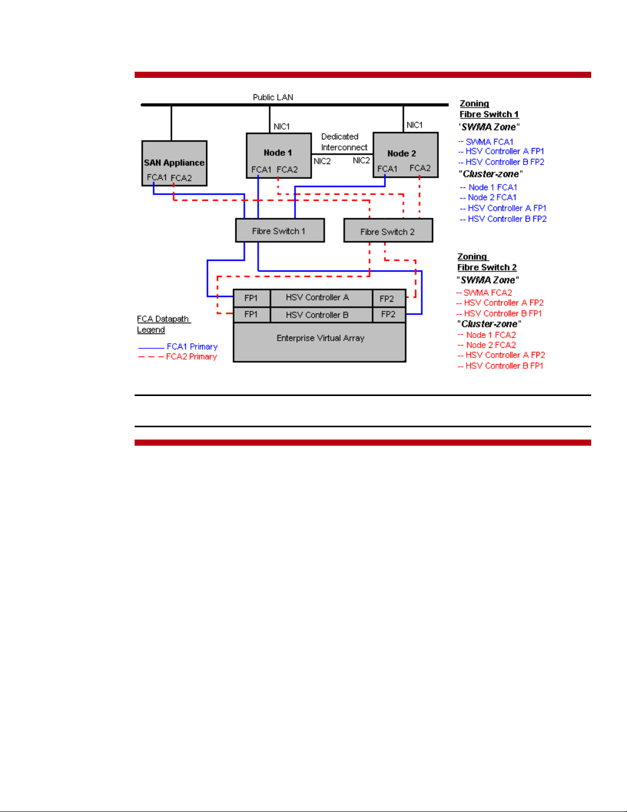
Hardware Cabling and Zoning Scheme
Figure 1. Hardware cabling and zoning scheme
Note: This diagram depicts a two-node cluster. Using Microsoft Windows Server 2003, Enterprise
Edition, HP supports up to eight (8) nodes in a ProLiant Cluster F500 for EVA.
Introduction
Microsoft Windows Server 2003, Enterprise Edition is an extension of the Microsoft Windows 2000
operating system environment developed to enhance the customer experience and to improve the
overall usability and deployment.
General cluster improvements for Microsoft Windows Server 2003, Enterprise Edition include:
• Larger cluster sizes – Enterprise Edition now supports up to 8 nodes.
• Enhanced cluster installation wizard – built-in validation and verification function to
help ensure base components are ready to be clustered.
• Installation – cluster binaries are automatically copied during the operating system
installation.
• Multi-node addition – multiple nodes can be added in a single operation instead of one
by one.
• Active Directory integration – tighter integration including a “virtual” computer object,
Kerberos authentication, and a default location for services to publish service control points.
Users can access the virtual server just like any other Windows server.
3
Page 4

This checklist provides step-by-step ProLiant Cluster F500 for EVA operating system installation and
cluster configuration directions using Microsoft Windows Server 2003, Enterprise Edition.
Software and Hardware Pre-Checks
The following table provides a checklist of the required software versions and, if applicable, any items
to execute before beginning the installation. Place a checkmark (3) in the box after completing each
step.
3
Before installing your HP ProLiant F500 for EVA cluster solution, it is very important to refer to the HP Cluster
Configuration Support website for details on components that make up a valid cluster configuration. There is a support
matrix for each HP Cluster that details components that represent quality tested and supported HP Cluster
configurations.
Using the link below, select the appropriate operating system and storage platform and then refer to the row of
deliverables that are relevant to the configuration you require.
The HP Cluster Configuration Support website can be found at
http:/h18022.www1.hp.com/solutions/enterprise/highavailability/answercenter/configuration-all.html
SmartStart CD.
Two to eight supported ProLiant Servers, two supported Fibre Channel Adapters (FCA) per server, two or more
supported network adapters per server, two supported fibre channel switches or hubs, and one or more EVAs per
cluster.
Review and understand any Read This First (RTF) and Getting Started cards that were shipped with the product.
Microsoft Windows Server 2003, Enterprise Edition software and documentation.
If applicable, Microsoft Windows Server 2003, Enterprise Edition Service Pack.
HP Insight Manager (optional).
One HP OpenView Storage Management Appliance.
HP StorageWorks Command View EVA software.
Software and Hardware Pre-Checks
HP StorageWorks Windows Kit for Enterprise Virtual Array for FCA driver.
EVA firmware for EVA5000 or EVA firmware for EVA3000.
FCA firmware and boot bios.
Fibre Channel switch firmware.
HP StorageWorks Secure Path for Windows (Included in the ProLiant Cluster F500 for the Enterprise SAN Cluster Kit).
Sufficient software rights to install the operating system and software applications on each node.
Ensure all hardware is installed and properly cabled as shown in figure 1 - hardware cabling diagram on page 3.
Install the NICs for the private network (cluster heartbeat interconnect) and the public network in each cluster node.
Install the FCAs in each cluster node.
Best Practice: If the server is equipped with multiple buses, it is recommended to install each FCA on a different bus.
Cable the private NIC in each cluster node. You may use the Ethernet Crossover cable included in your cluster kit if
desired for a two-node cluster.
Cable the FCAs to the switches (or hubs) in each cluster node.
4
Page 5

Note: The configuration steps detailed in this document are for a switched environment only.
Cable the EVA storage subsystem(s) to the switches or hubs.
Cable the LAN using an Ethernet cable from the public NIC in each cluster node to the public LAN switch or hub.
Gathering Information
The following table provides a checklist for the required input parameters that will facilitate the
operating system and cluster installation. Write the information in the values column next to each item.
Place a checkmark (3) in the box after completing each step.
3
Name for each node (Microsoft
Windows Server 2003, Enterprise
Edition supports up to eight (8) nodes
in a cluster):
Public network connection IP address
and subnet mask for each node:
Private network connection (cluster
heartbeat) IP address and subnet mask
for each node:
Item Values
Node 1: Node 2:
Node 3: Node 4:
Node 5: Node 6:
Node 7: Node 8:
Node 1 Node 2
IP address:
Subnet mask:
Node 3 Node 4
IP address:
Subnet mask:
Node 5 Node 6
IP address:
Subnet mask:
Node 7 Node 8
IP address:
Subnet mask:
Node 1 Node 2
IP address:
Subnet mask:
Node 3 Node 4
IP address:
Subnet mask:
Node 5 Node 6
IP address:
Subnet mask:
Node 7 Node 8
IP address:
Subnet mask:
IP address:
Subnet mask:
IP address:
Subnet mask:
IP address:
Subnet mask:
IP address:
Subnet mask:
IP address:
Subnet mask:
IP address:
Subnet mask:
IP address:
Subnet mask:
IP address:
Subnet mask:
5
Page 6

WWID, slot number, and bus of each
FCA for each node:
Node 1 Node 2
FCA 1 WWID:
FCA 1 slot and bus:
FCA 2 WWID:
FCA 2 slot and bus:
FCA 1 WWID:
FCA 1 slot and bus:
FCA 2 WWID:
FCA 2 slot and bus:
Cluster name:
Cluster IP address and subnet mask:
Default gateway address:
WINS server address:
DNS address:
Local machine Administrator password
(used during OS installation):
Domain name:
Domain administrator user name and
password (used during OS installation
to have the machine join the domain):
Domain account name and password
for cluster service (this account has
special privileges on each cluster
node):
Node 3 Node 4
FCA 1 WWID:
FCA 1 slot and bus:
FCA 2 WWID:
FCA 2 slot and bus:
Node 5 Node 6
FCA 1 WWID:
FCA 1 slot and bus:
FCA 2 WWID:
FCA 2 slot and bus:
Node 7 Node 8
FCA 1 WWID:
FCA 1 slot and bus:
FCA 2 WWID:
FCA 2 slot and bus:
IP address:
Subnet mask:
IP address:
IP address:
IP address:
Know the Administrator password
Know the user name and password
Know the user name and password
FCA 1 WWID:
FCA 1 slot and bus:
FCA 2 WWID:
FCA 2 slot and bus:
FCA 1 WWID:
FCA 1 slot and bus:
FCA 2 WWID:
FCA 2 slot and bus:
FCA 1 WWID:
FCA 1 slot and bus:
FCA 2 WWID:
FCA 2 slot and bus:
Configuring the HP OpenView Storage Management Appliance
The following table provides a checklist of the configuration steps for the HP OpenView Storage
Management Appliance. Place a checkmark (3) in the box after completing each step.
6
Page 7

3
p
Connect the EVA to the Fibre Channel switches. The F500 supports the cross-cable configuration. Please verify that the
cabling is configured using this supported method.
For more information regarding the F500, please visit
http://h18000.www1.hp.com/solutions/enterprise/highavailability/microsoft/haf500/index-eva.html
Power on the EVA subsystem.
Enter the WWID of the subsystem via the Operator Control Panel (OCP).
Power on the HP OpenView Storage Management Appliance. Refer to the HP OpenView Storage Management
Appliance documentation for detailed installation and configuration instructions.
http://h18000.www1.hp.com/products/sanworks/managementappliance/documentation.html
Log into the Storage Management Appliance from any network browser.
Note: The default username and password is administrator.
Install the HP StorageWorks Command View EVA software for the Storage Management Appliance.
Insert the HP StorageWorks Command View EVA CD. Select Application →Installation Services→Install
Products. Select CDROM→Next Step and follow the on-screen instructions to continue.
Cable the Storage Management Appliance to the SAN. Refer to figure 1 - hardware cabling diagram on page 3.
Connect the Storage Management Appliance to the ethernet network.
Note: You must have a working network to configure the storage subsystem via the Storage Management Appliance.
Configuring the HP OpenView Storage Management Appliance
Configure the zone for the Storage Management Appliance.
Using telnet or the Fibre Channel switch graphical user interface (GUI), create a Fibre Channel zone that consists of the
WWIDs of the FCAs in the Storage Management Appliance and the WWIDs of the HSV controller ports.
For more information regarding zoning, please refer to the Zoning User’s Guide located at
http://h18004.www1.hp.com/solutions/enterprise/highavailability/whitepapers/ms-eva.html
Installing Node 1 Operating System
The following table provides a checklist of the operating system installation steps for Node 1. Place a
checkmark (3) in the box after completing each step.
3
Power on Node 1.
After the array controller initializes, press the F8 key to enter the Option ROM Configuration for Arrays (ORCA).
Create a primary boot partition on the server.
Exit the ORCA utility.
Boot the server with the SmartStart CD in the CD-ROM drive.
Note: The instructions below are for SmartStart 6.x or later. Please refer to SmartStart 5.50 documentation for preGeneration 2 servers.
Installing Node 1 Operating System
Select the desired language from the Select Language screen.
Follow the SmartStart on-screen instructions. Insert the operating system CD when prompted to complete the installation
process.
Each cluster node requires at least two network adapters—one connected to a public network, and one connected to a
private network.
For the public network connection:
lex mode. The speed for the network adapter should be hard set (manually set) to be the same on all nodes
and du
If the network adapter can transmit at multiple speeds, then manually specify a speed
7
Page 8

according to the card manufacturer's specification.
Best Practice: To provide a maximum level of redundancy, use NIC Teaming capabilities for selected HP network
products to provide a redundant public network connection. Please note, however, that NIC Teaming is not supported
for the private network connection.
Configure the TCP/IP settings for the public network connection.
For the private network connection:
Microsoft Knowledge Base (KB) article 258750 to properly setup the private network.
http://support.microsoft.com/default.aspx?scid=kb;en-us;258750
Configure the TCP/IP settings for the private network connection.
Join the Microsoft Windows Domain and reboot when prompted.
After the reboot, log the machine into the domain.
Install the FCA device drivers.
Insert the HP StorageWorks Windows Kit for Enterprise Virtual Array CD into the server CD-ROM drive. If autorun is
enabled, the installation program starts. Otherwise, navigate to the root of the CD and double-click launch.exe.
Click Solution Software for Windows NT/2000/Server 2003. Click Perform Multi Driver
Update/Install to start the driver update utility.
Note: When the driver update utility installation finishes, DO NOT reboot. Proceed to the next step before rebooting.
Install the Fibre Channel software.
Select Run Fibre Channel Utility to start the Fibre Channel setup wizard. If more than 5 Windows servers will have
exclusive access to the same EVA, the Extended Configuration option should be selected.
Reboot after the installation of the Fibre Channel software.
Install HP StorageWorks Secure Path for Windows software.
Insert the HP StorageWorks Secure Path for Windows CD into the server CD-ROM drive. Select Install secure path
and follow the on-screen instructions.
To eliminate possible private network cluster communication issues, refer to
Note: Verify that reverse lookup is configured correctly on the Domain Name System (DNS) server if you are using Fully
Qualified Domain Names (FQDN).
Reboot Node 1.
Configure the cluster zone for Node 1.
Using telnet or the Fibre Channel switch graphical user interfaces (GUI), configure the cluster zone. The cluster zone will
consist of the WWIDs of the FCA in Node 1 and the WWIDs of the HSV controller ports.
For more information regarding zoning, please refer to Zoning User’s Guide located at
http://h18004.www1.hp.com/solutions/enterprise/highavailability/whitepapers/ms-eva.html
Note: After installing the FCA driver and Fibre Channel Software, the FCA will register its WWID with the fabric switch.
There should be a minimum of two zones created. One of the zones will consist of the Storage Management Appliance
and the HSV controller ports, and the other zone will consist of both cluster nodes and the HSV controller ports.
When the installation is complete, shutdown Node 1.
Installing Node 2+ Operating System
The following table provides a checklist of the operating system installation steps for Node 2+. Place
a checkmark (3) in the box after completing each step.
Note: Microsoft Windows Server 2003, Enterprise Edition supports a maximum of 8 cluster nodes.
Repeat the following operating system installation steps for each additional node.
8
Page 9

3
Power on Node 2.
After the array controller initializes, press the F8 key to enter the Option ROM Configuration for Arrays (ORCA).
Create a primary boot partition on the server.
Exit the ORCA utility.
Boot the server with the SmartStart CD in the CD-ROM drive.
Note: The instructions below are for SmartStart 6.x or later. Please refer to SmartStart 5.50 documentation for preGeneration 2 servers.
Select the desired language from the Select Language screen.
Follow the SmartStart on-screen instructions. Insert the operating system CD when prompted to complete the installation
process.
Each cluster node requires at least two network adapters—one connected to a public network, and one connected to a
private network.
For the public network connection:
and duplex mode. The speed for the network adapter should be hard set (manually set) to be the same on all nodes
according to the card manufacturer's specification.
Best Practice: To provide a maximum level of redundancy, use NIC Teaming capabilities for selected HP network
products to provide a redundant public network connection. Please note, however, that NIC Teaming is not supported
for the private network connection.
Configure the TCP/IP settings for the public network connection.
For the private network connection:
Microsoft Knowledge Base (KB) article 258750 to properly setup the private network.
http://support.microsoft.com/default.aspx?scid=kb;en-us;258750
Configure the TCP/IP settings for the private network connection.
Join the Microsoft Windows Domain and reboot when prompted.
After the reboot, log the machine into the domain.
Install the FCA device drivers.
Insert the HP StorageWorks Windows Kit for Enterprise Virtual Array CD
enabled, the installation program starts. Otherwise, navigate to the root of the CD and double-click launch.exe.
Click Solution Software for Windows NT/2000/Server 2003. Click Perform Multi Driver
Install/Update to start the driver update utility.
Note: When the driver update utility installation finishes, DO NOT reboot. Proceed to the next step before rebooting.
Installing Node 2+ Operating System
If the network adapter can transmit at multiple speeds, then manually specify a speed
To eliminate possible private network cluster communication issues, refer to
into the server CD-ROM drive. If autorun is
Install the Fibre Channel software.
Select Run Fibre Channel Utility to start the Fibre Channel setup wizard. If more than 5 Windows servers will have
exclusive access to the same EVA, the Extended Configuration option should be selected.
Reboot after the installation of the Fibre Channel Software.
Install HP StorageWorks Secure Path for Windows software.
Insert the HP StorageWorks Secure Path for Windows CD into the server CD-ROM drive. Select Install secure path
and follow the on-screen instructions.
Note: Verify that reverse lookup is configured correctly on the Domain Name System (DNS) server if you are using Fully
Qualified Domain Names (FQDN).
Reboot Node 2.
Configure the cluster zone for Node 2.
Using telnet or the Fibre Channel switch graphical user interfaces (GUI), configure the cluster zone. The cluster zone will
consist of the WWID of the FCAs in Node 2 and the WWIDs of the HSV controller ports. For more detail information
regarding zoning, please refer to the Zoning User’s Guide located at
http://h18000.www1.hp.com/solutions/enterprise/highavailability/whitepapers/ms-eva.html
Note: After installing the FCA driver and Fibre Channel software, the FCA will register its WWID with the fabric switch.
There should be a minimum of two zones created. One of the zones will consist of the Storage Management Appliance
and the HSV controller ports, and the other zone will consist of both cluster nodes and the HSV controller ports.
9
Page 10

When the installation is complete, shutdown Node 2.
Microsoft Windows Server 2003, Enterprise Edition supports up to 8 nodes in a cluster. Repeat the installation
instructions on any additional nodes that will join the cluster.
Configuring the Shared Storage
The following table provides a checklist of the steps necessary to configure the EVA shared storage.
Place a checkmark (3) in the box after completing each step.
3
Power on both nodes and log into the network domain.
Verify the FCAs have the most current supported firmware.
Verify the FCAs firmware by accessing the lputilnt utility. However, do not make any driver parameter changes using this
utility.
Select Start Æ run Æ \winnt\system32\lputilnt
Log into the Storage Management Appliance.
Launch HP StorageWorks Command View EVA.
Select Devices→Command view
Click on the uninitialized storage subsystem by clicking on Uninitialized Storage System→ Initialize.
Note: If this is the first time the Storage Management Appliance sees the EVA, a basic license is required to continue
configuring the subsystem.
Configure the disk groups. A disk group cannot contain less than eight disks.
Note: Decide how many disk groups are going to be created on the subsystem. The EVA can be configured with a
single default disk group that consists of all the physical disks in the subsystem or it can be configured with multiple disk
groups.
Set the storage subsystem time.
Add all cluster nodes to the EVA.
Select your EVA and then select Hosts. Click Add a Host and enter a host name and IP address. Click Next Step
and enter an adapter port World Wide ID (WWID). Use the information that was gathered before installing the FCAs in
the server. Select Microsoft Windows as the operating system. Click Next Step. Click Finish, OK.
Configuring the Shared Storage
Note: If the wrong IP address is entered and saved, it cannot be changed. You will have to delete and recreate the host.
Add the second FCA to the host.
Click Add a Port. Select the second FCA from the list that was installed in the host. Click Finish, OK.
Repeat these steps for the second host.
Create Virtual Disks.
Select Virtual Disks. Click Create VD Fam. Enter a virtual disk name. Select Vraid. Select a preferred path - either
Path A-Failover only or Path B-Failover only. Click Finish, OK.
Repeat these steps to create the virtual disks that are required.
Note: With Windows hosts, the only supported path settings are either Path A-Failover only or Path B-Failover
only. A windows host requires Secure Path to manage the failover/failback operations.
Present the Virtual Disks to the cluster nodes.
Select a virtual disk, click Present. Select a host. Click Finish, OK. Click Present. Select the second host. Click
Finish, OK.
Select another virtual disk and repeat these steps until all the virtual disks in the cluster are presented to all hosts.
Note: Verify that the LUNs are presented to all nodes with the same LUN number.
10
Page 11

Configure the Virtual Disks on Node 1.
Power down Node 2. From the desktop of Node 1, select Start Æ Programs Æ Administrative Tools Æ
Computer Management. Then select Disk Management to create volumes out of the logical drives.
Note: Configure the virtual disks on one node at a time. Do not upgrade the logical drives from Basic to Dynamic.
Microsoft Cluster Services does not support dynamic disks.
Be sure to assign drive letters and format the volumes as NTFS partitions. It is a good practice to provide a volume label
to help identify the drives.
Close Disk Management.
Creating the Cluster
The following table provides a checklist for creating the cluster from Node 1. Place a checkmark (3)
in the box after completing each step.
3
From the desktop of Node1:
Select Start Æ Programs Æ Administrative Tools Æ Cluster Administrator.
Select Create New Cluster from the Action drop-down box. Click OK.
Click Next on the welcome screen.
Select the domain to create the cluster in and enter a name for the cluster. Click Next.
Enter the name of the first server to be in the cluster. Click Next.
When the cluster configuration wizard finishes analyzing the configuration, click Next.
Enter the IP address for the cluster. Click Next.
Enter the username and password for the cluster. Click Next.
Verify the proposed cluster configuration. Click Next.
When the cluster configuration wizard has finished creating the cluster, click Next and then click Finish.
Select Start Æ Control Panel Æ HP Management Agents. In the list of Inactive Agents, select Clustering
Information and click Add to move this agent to the list of active agents and click OK.
Restart the agents when prompted.
Creating the Cluster
Joining Node 2+ to the Cluster
The following table provides a checklist for the process of joining Node 2+ to the cluster. Place a
checkmark (3) in the box after completing each step.
Note: Microsoft Windows Server 2003, Enterprise Edition supports a maximum of 8 cluster nodes.
Repeat the following steps for each additional node.
3
Power on Node 2.
From Node 2, select Start Æ Programs Æ Administrative Tools Æ Cluster Administrator.
Select Add nodes to cluster from the Action drop-down box. Enter the name of the cluster to join, click OK.
Click Next on the welcome screen.
Enter the name of the server that you want to join the cluster, click Add and the click Next.
When the cluster configuration wizard finishes analyzing the configuration, click Next.
Enter the user name and password for the cluster. Click Next.
Verify the proposed cluster configuration. Click Next.
Joining Node 2+ to the Cluster
11
Page 12

When the cluster configuration wizard has finished adding the node to the cluster, click Next and then click Finish.
Select Start ÆControl Panel Æ HP Management Agents. In the list of Inactive Agents, select Clustering
Information and click Add to move this agent to the list of active agents and click OK.
Restart the agents when prompted.
Microsoft Windows Server 2003, Enterprise Edition supports up to 8 nodes in a cluster. Repeat the joining node 2+
to the cluster installation instructions for each additional node.
Validating the Cluster Configuration
To validate the cluster installation, perform the following steps from any cluster node. Place a
checkmark (3) in the box after completing each step.
3
From the desktop of any node:
Select Start Æ Programs Æ Administrative Tools Æ Cluster Administrator, and connect to the cluster.
Right click on one of the cluster groups and select Move Group.
Verify the group fails over and all resources come online.
Right click on the same cluster group and select Move Group.
Verify that the group fails over and all resources come online.
Repeat the validating the cluster configuration steps, for each group.
Validating the Cluster Configuration
The installation is now complete.
12
Page 13

For more Information
To learn more about HP High Availability and ProLiant Clusters visit the following Web site:
http://www.hp.com/servers/proliant/highavailability
.
Feedback
Help us improve our technical communication. Let us know what you think about the technical
information in this document. Your feedback is valuable and helps us structure future communications.
Please send your comments to hawebserver@hp.com
.
365192- 001
© 2004 Hewlett-Packard Development Company, L.P. The information
contained herein is subject to change without notice. The only warranties for
HP products and services are set forth in the express warranty statements
accompanying such products and services. Nothing herein should be construed
as constituting an additional warranty. HP shall not be liable for technical or
editorial errors or omissions contained herein.
Microsoft and Windows are U.S. registered trademarks of Microsoft
Corporation.
Printed in the USA
5982-6050EN, 05/2004
13
 Loading...