

Page 1

HP StorageWorks
ESL E-Series Ta
pe Library users guide
350799-010
Part number: 350799-010
enth edition: September 2007
T
Page 2

Legal and notice information
© Copyright 2004-2007 Hewlett-Packard Development Company, L.P.
The information contained herein is subject to change without notice. The only warranties for HP products and ser vices are set forth
in the express warranty statements accompanying such products and services. Nothing herein should be construed as constituting
an additional warranty. HP shall not be liable for technical or editorial errors or omissions contained herein.
Page 3

Contents
Aboutthisguide ......................... 11
Relateddocumentation................................... 11
Documentconventionsandsymbols ............................. 11
HPtechnicalsupport.................................... 12
Subscriptionservice .................................... 12
OtherHPwebsites .................................... 12
HP-authorizedreseller ................................... 12
1 Library overview . . . ..................... 13
Librarycomponents .................................... 13
Librarycabinet .................................... 13
Frontpanel.................................... 13
Backpanel.................................... 14
Operatorcontrolpanel(OCP).............................. 15
Libraryrobotics .................................... 16
Switchfortheinternalnetwork.............................. 18
Tapedrives...................................... 18
Cleaningcartridges ................................ 18
Ultrium460,460-FC,960,and1840tapedrives ................... 19
SDLT320and600tapedrives ........................... 19
Tapecartridges .................................... 19
Ultriumtapecartridges............................... 20
SDLT320and600tapecartridges.......................... 21
Loadportsandmagazines ............................... 21
Cardcageandcontrollers ............................... 22
e2400-160 FC, e2400-FC 2G, and e2400–FC 4G interface controllers . . . . . . . . . . 23
LAN-freebackupandrestore ............................ 26
SCSIoverIPProtocol(SIPP) ............................... 27
InterfaceManagercard ................................ 27
CrossLinkedlibraries.................................... 29
CrossLinkcabinetsfunctionality ............................. 29
Spacerequirements .................................. 30
Systemcomponents .................................. 30
LockElementAddressing ................................ 32
Librarystoragelocationsandslotnumbering.......................... 32
Ultriumlibrary..................................... 36
SDLTlibrary...................................... 38
Mixedmedialibrary.................................. 40
2Libraryoperations ........................ 43
TakingESDprecautions................................... 43
Preparingtapecartridges.................................. 45
Labelingtapecartridges ................................ 45
Ultriumbarcodelabels............................... 46
SDLTbarcodelabels................................ 47
Media label identifiers............................... 48
Settingthewrite-protectswitch.............................. 49
Write-protectingUltriumtapecartridges........................ 49
Write-protectingSDLTtapecartridges......................... 49
Insertingtapecartridges .................................. 50
HP StorageWorks
3
Page 4

Closingthecabinetdoorsandaccesspanels ......................... 50
Poweringthelibraryonandoff ............................... 51
Poweringonthelibrary................................. 51
Placingthelibraryon-lineoroff-line ........................... 52
Poweringoffthelibrary................................. 52
UsingtheOCP ...................................... 52
Homescreen ..................................... 53
OCPbuttons ..................................... 54
OCPcomponents ................................... 55
Menuscreen ..................................... 57
Viewing library information (standalone libraries or primary cabinets only) . . . . . . . . . 58
Viewingcabinetinformation............................. 59
Viewing library health status information (standalone libraries only) . . . . . . . . . . . . 60
Viewingpartition(LockElementAddressing)information................. 61
Viewingandeditingsetupinformation ........................ 61
Viewing and editing the network settings (standalone libraries or primary cabinets only) . . . 64
Viewingtheeventlog ............................... 64
LoadPortsscreen ................................... 65
Operationsscreen................................... 66
Diagnosticsscreen................................... 67
Stopbutton...................................... 70
Inserting tape cartridges into a fixedloadport......................... 70
Usingremovablemagazines ................................ 70
Insertremovablemagazines............................... 71
Removeremovablemagazines.............................. 72
3Maintenanceandtroubleshooting................. 73
Start-upproblems ..................................... 73
Thelibrarydoesnotpoweron.............................. 73
The library or tape drives are not detected by the Interface Manager or Command View TL software 73
Duringinitialization,thelibraryreports“notready”..................... 73
Oneormoretapedrivesfailtospinupduringstart-up ................... 74
OCPproblems ...................................... 74
TheOCPisblank ................................... 74
TheOCPdoesnotrespondtobuttons........................... 74
Anerrormessageisdisplayed.............................. 74
Roboticsproblems..................................... 74
Therobotdoesnotmoveatpoweron........................... 74
Thepickerpartiallygripsatapecartridge......................... 74
Thebarcodereaderfails ................................ 74
Therobottimesoutorhangs .............................. 75
Therobotfailsduringanoperation............................ 75
Therobotdropsacartridge............................... 75
A cartridge is in the picker at start-up, when a move command is requested, or after a place command
isexecuted...................................... 75
The picker does not have a cartridge after completing a pick command . . . . . . . . . . . . 75
Operatingproblems .................................... 75
Thehostcomputercannotcommunicatewiththelibrary................... 75
Atapecartridge(medium)isreportednotpresent ..................... 75
Amovecommandfailed ................................ 76
A flashmemoryerrorisreported............................. 76
Amaximumtemperatureexceededwarningisdisplayed .................. 76
Switchproblems...................................... 76
Tapedriveproblems.................................... 77
Thelibraryisunabletocommunicatewithadrive ..................... 77
Thetapedrivedoesnotejectacartridge ......................... 77
InterfaceManagercardproblems .............................. 78
StatusLEDdiagnosticcodes............................... 78
Networklinkactivity/speedLEDs ............................ 78
4
Page 5

CommonInterfaceManagerissues............................ 78
CommandViewTLserverdoesnotdetecttheInterfaceManagercard........... 78
Interface Manager card does not detect one or more FC interface controllers . . . . . . . . 79
Interface Manager card does not detect drives or library . . . . . . . . . . . . . . . . . 79
CommandViewTLdoesnotruninthebrowser..................... 80
FCinterfacecontrollerproblems............................... 80
LEDindicators..................................... 80
Basictroubleshooting.................................. 82
Verifying SCSI bus configuration............................. 83
VerifyingFCportconnection .............................. 83
VerifyingFCandSCSIdevicesinWindowsNT....................... 83
Verifying the interface controller configuration ....................... 84
Verifyingdevices ................................... 84
Verifying the host configuration ............................. 84
VerifyingHBAdevicedriverinformation.......................... 84
Verifying serial port configuration ............................ 84
Maintainingtapecartridges................................. 85
Cleaningtapedrives.................................... 85
CleaningSDLTtapedrives ............................... 85
CleaningUltriumtapedrives .............................. 86
ALibrarycharacteristics ...................... 87
Physical specificationsandrequirements............................ 87
Performanceandreliabilitycharacteristics........................... 88
Environmental specifications................................. 88
BRelocatingthelibrary ...................... 91
Checkingthenewinstallationsite .............................. 91
Preparingthelibraryforrelocation.............................. 91
Removingtapecartridges................................ 92
Installingshippingrestraintsandpacking ......................... 92
Disconnectinglibrarycables............................... 99
Cratingthelibrary..................................... 100
Preparingthelibraryforoperation.............................. 102
CRegulatorystatements ...................... 103
FCCstatement ...................................... 103
BSMIstatement ...................................... 103
Japan statement (VCCI) . . . . . . . . . . . . . . . . . . . . . . . . . . . . . . . . . . . 103
Japan statement (AC power cords) . . . . . . . . . . . . . . . . . . . . . . . . . . . . . . 103
IndustryCanada(digitalapparatus) ............................. 103
CISPR-22WARNING! ................................. 104
ACHTUNG! ..................................... 104
ATTENTION! ..................................... 104
NoticeforUSAandCANADAonly ............................. 104
ATTENTION ..................................... 104
REMARQUE ..................................... 104
Laserstatement ...................................... 104
Class1laserproduct.................................. 104
Laserklasse1..................................... 105
Appareil à laser de classe 1 . . . . . . . . . . . . . . . . . . . . . . . . . . . . . . . 105
Productoláserdeclase1................................ 105
Luokan1laserlaite................................... 105
Batterystatement ..................................... 106
LETOP........................................ 106
VAROITUS ...................................... 106
ATTENTION ..................................... 106
ACHTUNG...................................... 106
HP StorageWorks
5
Page 6

Attenzione ...................................... 106
PRECAUCIÓN .................................... 107
VARNING!...................................... 107
WasteElectricalandElectronicEquipmentdirective....................... 107
DSensedatavalues........................ 113
EEventreporting ......................... 123
Criticalevents....................................... 123
Warningevents...................................... 126
Informationevents..................................... 128
Glossary............................. 135
Index .............................. 139
6
Page 7

Figures
1
2
3 OCP ..................................... 16
4
5
6
7
8
9
10
11
12
13
14 CLMarm ................................... 30
15
16
17
Librarycabinet—frontview............................ 14
Librarycabinet—backpanels........................... 15
Library robo
Portsontheswitchfortheinternalnetwork ..................... 18
LTO tape dri
Loadports(leftandright) ............................ 22
Cardcagewithcontrollers............................ 23
e2400-160FCinterfacecontroller ........................ 24
e2400-FC2Ginterfacecontroller......................... 24
e2400-FC4Ginterfacecontroller......................... 25
LAN-freebackupandrestore........................... 27
Multiplelibrariesconnectedtoasinglemanagementstation ............. 29
CLMroboticscontroller ............................. 31
CLMsensorboard ............................... 31
CLMmotorassembly .............................. 32
tics................................. 17
ves................................. 19
18
Slidingtheslotpanelsoutofthecabinet...................... 33
19
Binshelfnumbering,leftpanels.......................... 34
20
Binshelfnumbering,rightpanels ......................... 35
21
Binshelfnumbering,backpanel ......................... 36
22
23
24
25
26
27
28
29
3
31
32
33
34
0
chinganUltriumbarcodelabel........................ 46
Atta
ProperUltriumbarcodelabelplacement...................... 47
ertinganSDLTbarcodelabel ......................... 48
Ins
Write-protectingUltriumtapecartridges ...................... 49
Write-protectingSDLTtapecartridges ....................... 50
Closingthefrontdoor.............................. 51
osingthebackdoor.............................. 51
Cl
Homescreenonstandalonelibrary ........................ 54
omescreenonprimarylibrary ......................... 54
H
Homescreenonsecondarylibrary ........................ 54
Menuscreen.................................. 58
Libraryscreen(standaloneonly).......................... 59
Libraryscreen(primaryonly)........................... 59
HP StorageWorks
7
Page 8

35
Cabinetscreen................................. 60
36
HealthStatusscreenwhennoerrorsexist...................... 61
37
Setup screen (s
38
Setupscreen(primarycabinet) .......................... 62
39
Setupscreen(secondarycabinets)......................... 62
40
Network Settings screen on standalone libraries or primary cabinets . . . . . . . . . . 64
41
EventLogscreenonalllibrariesandcabinets.................... 65
42
LoadPortsscreenonalllibrariesandcabinets ................... 65
43
Operationsscreen(standalonelibrary)....................... 66
44
Operationsscreen(primarycabinet)........................ 66
tandalonelibrary) ......................... 62
45
Operatio
46
Diagnosticsscreen(standalonelibrary)....................... 69
47
Diagno
48
Diagnosticsscreenonsecondarycabinet...................... 69
49
Diagnostics confirmation remaining offline ..................... 70
50
Identifytheremovablemagazinemediatype.................... 71
51
Inserttheremovablemagazine.......................... 72
52
LEDsontheswitchfortheinternalnetwork ..................... 76
53
e2400
54
e2400-FC2GinterfacecontrollerLEDs....................... 81
55
e2400-FC4GinterfacecontrollerLEDs....................... 82
56
Retrievingthepanelshippingrestraints....................... 92
57
Attachingthepanelshippingrestraints....................... 93
58
Shippingrestraints-storagelocation........................ 94
59
Installingthecounterweightshippingrestraint.................... 95
60
Installingtheroboticshippingrestraint....................... 96
1
6
Installingtheinternallibraryframerestraint..................... 97
nsscreen(secondarycabinet)....................... 67
sticsscreen(primarycabinet)........................ 69
-160FCinterfacecontrollerLEDs ...................... 81
62
Addingtheshippingfoaminsidethelibrary .................... 98
3
6
Addingtheshippingfoamtothelibraryperimeter.................. 99
64
Cratingthelibrary ............................... 101
8
Page 9

Tables
1 Documentconventions.............................. 11
2
3
4
5
OCPfeatures ................................. 16
Ultriumcompatibility .............................. 20
Ultriumlibrarystorageelements(removablemagazines) ............... 37
Ultrium library storage elements (fixedmagazines).................. 38
6
SDLT library
7
SDLT library storage elements (fixedmagazines)................... 40
8
Media label
9
OCP components for a standalone library or the primary cabinet of a Cross Linked system . 56
10
OCPcomponentsforasecondarycabinetofaCrossLinkedsystem .......... 57
11
Diagnostictests................................. 67
12
SwitchLEDs .................................. 77
13
StatusLEDdiagnosticcodes ........................... 78
14
Networklinkactivity/speedLEDs......................... 78
15
Terminal configurationsettings .......................... 84
16
Physica
17
Interfaces ................................... 87
18
Performancecharacteristics............................ 88
19
Reliabilitycharacteristics............................. 88
20
21
22
23
24 Warningevents ................................ 127
onmental specifications ........................... 89
Envir
Sensedatavalues(hexadecimal) ......................... 113
HardwarefailureASCQvalues.......................... 122
Criticalevents ................................. 123
storageelements(removablemagazines) ................ 39
identifiers.............................. 48
lcharacteristics ............................. 87
25
Informationevents ............................... 129
HP StorageWorks
9
Page 10

10
Page 11

About this guide
This guide provides information to help you:
• Operate the tape library.
• Relocatethetapelibrary.
• Troubleshoot the tape library.
Related docum
The following documents provide related information:
• HP StorageWo
• HP StorageWorks ESL E-Series unpacking and installation guide
• HP StorageWorks ESL E-Series Tape Library service manual
entation
rks ESL E-Series Tape Library site survey
Document conventions and symbols
Table 1 Document conventions
Convention
Blue text: Table 1
Blue, underlined text: http://www.hp.com Web site addresses
Bold text
Italic text Text emphasis
Monospace text
Monospace, italic text
Monospace, bold text
Element
Cross-reference links and E-mail addresses
• Keys that are pressed
• Text typed into a GUI element, such as a box
• GUI elements that are clicked or selected, such as
menu and list items, buttons, tabs, and check boxes
• File and directory names
• System output
• Code
• Commands, their arguments, and argument values
• Code
• Comm
Emphasized monospace text
variables
and variables
WARNING!
Indicates that failure to follow directions could result in bodily harm or death.
CAUTION:
Indicates that failure to follow directions could result in damage to equipment or data.
HP StorageWorks
11
Page 12

NOTE:
Provides additional information.
HP technical support
Telephone numbers for worldwide technical support are listed on the HP support web site:
h
ttp://www.hp.com/support/.
Collect the following information before calling:
• Technical support registration number (if applicable)
• Product serial numbers
• Product model names and numbers
• Error messages
• Operating system type and revision level
• Detailed questions
For continuous qualit y improvement, ca lls may be recorded or monitored.
Subscription service
HP strongly recommends that customers register online using the Subscriber’s choice web site:
h
ttp://www.hp.com/go-e-updates.
Subscribing to this service provides you with E-mail updates on the latest product enhancements, newest
driver versions, and firmware documentation updates as well as instant access to numerous other product
resources.
After subscribing, locate your products by selecting Business support and then Storage under Product
Category.
Other HP web sites
For additional information, see the following HP web sites:
•h
ttp://www.hp.com
•http://www.hp.com/go/storage
•http://www.hp.com/service_locator
•http://www.docs.hp.com
HP-authorized reseller
For the name of your nea rest HP-authorized reseller:
• In the United States, call 1-800-282-6672.
• Elsewhere, visit the HP web site: h
telephone numbers.
ttp://www.hp.com.ThenclickContact HP to find locations and
12
About this guide
Page 13

1Libraryoverview
This chapter describes both the ESL E-Series tape library and its components. The chapter consists of:
• Library components
• Cross Linked libraries
• Library storage locations and slot numbering
Library components
The ESL E-Ser
•Librarycabinet
• Operator control panel (OCP)
• Library rob
• Switch for the internal network
• Tape drives
• Tape catrid
• Load por ts and m agazines
• Card cage and controllers
•SCSIoverI
• Interface Manager card
Library cabinet
The cabinet houses all library components, including:
• Media picker
• Storage bins
• Control electronics
• Power supply and distribution equipment
• Tape drives
• Card cage with Fibre Channel (FC) interface controllers and robotics controller
• Interface Manager card
ies tape library consists of the several major components, detailed in:
otics
ges
PProtocol(SIPP)
You can access these components through the front and back doors of the library cabinet.
Front panel
Thefrontofthelibrarycabinet(seeFigure 1) provides the following:
• The fr
• The viewing window m a kes it possible to visually monitor library operations.
• An Operator Control Panel (OCP) in the center of the do or enables you to monitor and control
• Two configurable load ports allow easy insertion of cartridges, or removable magazines, without
ont doors provide easy access to the media picker and the storage array.
ry operations.
libra
opening the library door.
HP StorageWorks
13
Page 14

1
3
4
5
6
2
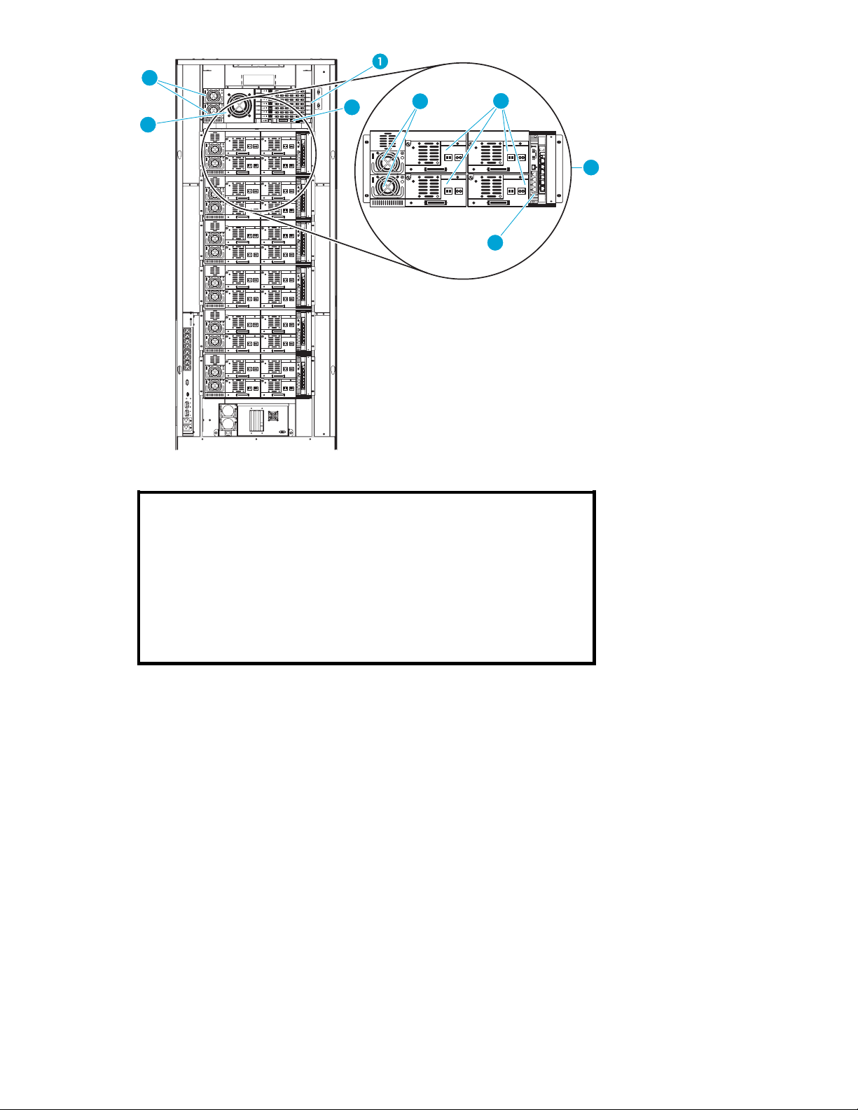
Back panel
The back of the library cabinet (see Figure 2)provideseasyaccessto:
• Cooling fans
• Power, control, and data interfaces
• Tape drives
• Tape drive communication (cluster controller card and Interface Mana ger card)
• Card cage with FC interface controllers and a robotics controller card
1
Viewing
2
Left load port
3OCP
4
Power but ton (lift button guard to access)
5
Right load port
6
Ventilation and air filters
Figure
windows
1 Library ca bin et—front view
14
Library overview
Page 15
10819
2
5
4
LNK
LNK
LNK
LNK
LNK
LNK
CHANNEL
CHANNEL
CHANNEL
CHANNEL
CHANNEL
CHANNEL
SERIAL
ACT/
ACT/
ACT/
ACT/
ACT/
ACT/
FIBRE
FIBRE
FIBRE
FIBRE
FIBRE
FIBRE
PWR
PORT 1 PORT 0 ETHERNET
PORT 2
PORT 1 PORT 3
PORT 2
LNK
LNK
LNK
LNK
LNK
LNK
CHANNEL
CHANNEL
CHANNEL
CHANNEL
CHANNEL
CHANNEL
SERIAL
ACT/
ACT/
ACT/
ACT/
ACT/
ACT/
FIBRE
FIBRE
FIBRE
FIBRE
FIBRE
FIBRE
PWR
PORT 1 PORT 0 ETHERNET
PORT 2
PORT 1 PORT 3
PORT 2
LNK
LNK
LNK
LNK
LNK
LNK
CHANNEL
CHANNEL
CHANNEL
CHANNEL
CHANNEL
CHANNEL
SERIAL
ACT/
ACT/
ACT/
ACT/
ACT/
ACT/
FIBRE
FIBRE
FIBRE
FIBRE
FIBRE
FIBRE
PWR
PORT 1 PORT 0 ETHERNET
PORT 2
PORT 1 PORT 3
PORT 2
LNK
LNK
LNK
LNK
LNK
LNK
CHANNEL
CHANNEL
CHANNEL
CHANNEL
CHANNEL
CHANNEL
SERIAL
ACT/
ACT/
ACT/
ACT/
ACT/
ACT/
FIBRE
FIBRE
FIBRE
FIBRE
FIBRE
FIBRE
PWR
PORT 1 PORT 0 ETHERNET
PORT 2
PORT 1 PORT 3
PORT 2
LNK
LNK
LNK
LNK
LNK
LNK
CHANNEL
CHANNEL
CHANNEL
CHANNEL
CHANNEL
CHANNEL
SERIAL
ACT/
ACT/
ACT/
ACT/
ACT/
ACT/
FIBRE
FIBRE
FIBRE
FIBRE
FIBRE
FIBRE
PWR
PORT 1 PORT 0 ETHERNET
PORT 2
PORT 1 PORT 3
PORT 2
LNK
LNK
LNK
LNK
LNK
LNK
CHANNEL
CHANNEL
CHANNEL
CHANNEL
CHANNEL
CHANNEL
SERIAL
ACT/
ACT/
ACT/
ACT/
ACT/
ACT/
FIBRE
FIBRE
FIBRE
FIBRE
FIBRE
FIBRE
PWR
PORT 1 PORT 0 ETHERNET
PORT 2
PORT 1 PORT 3
PORT 2
LNK
LNK
LNK
LNK
LNK
LNK
CHANNEL
CHANNEL
CHANNEL
CHANNEL
CHANNEL
CHANNEL
SERIAL
ACT/
ACT/
ACT/
ACT/
ACT/
ACT/
FIBRE
FIBRE
FIBRE
FIBRE
FIBRE
FIBRE
PWR
PORT 1 PORT 0 ETHERNET
PORT 2
PORT 1 PORT 3
PORT 2
7
2
3
6
Operat
1
2
3
4
5
6
7
Card cage
Power su
pplies (2 per drive cluster and 2 per card cage)
Tape drives (up to 4 per drive cluster)
Card cage cooling fan
0
Cluster
Cluster controller card (1 per drive cluster)
Interface Manager card (SIPP-enabled configuration shown)
Figure 2 Library ca binet—ba c k panels
or control panel (OC P)
The OCP features a menu system for determining library status, configuring the library, and performing
certain diagnostic functions (see Figure 3).
HP StorageWorks
15
Page 16

1
OCP buttons
2GreenLED
Figure 3 OCP
The OCP consists of the following features (see Table 2):
Table 2 OCP features
1 2
Feature
OCP
OCP buttons
LED indicator
NOTE:
You c an also perform diagnostics using HP StorageWorks Library and Tape Tools (L&TT), available
from h
ttp://www.hp.com/support/tapetools.Additionally,youcanconfigure the library and monitor
library status using HP StorageWorks Command View TL that shipped with your product. For suppor t
information, visit h
Library robotics
The library robotics consists of the m ain components identified in Figure 4.
Description
The O CP displays library status information and allows you to access the library
menus. These menus allow you to view or change the library settings, run
demonstration programs, or run diagnostic tests.
The OCP is discussed in Using the OCP.
Use these
options or c ommands. The functionality of these buttons changes depending on
the currently displayed screen.
The green LED lights when the library is fully operational and ready to accept
host commands. It flashes while the library is transitioning from a READY state to
a NOT READY state. The library will not be READY during power-on self-tests,
when ma gazines are being released, or during access to certain menu items.
buttons in combination with the OCP to scroll through screens and select
ttp://www.hp.com/support/cvtl.
16
Library overview
Page 17

1
2
1
2
assembly
Picker
Vertical motor
Figure 4 Library robotics
The vertical and horizontal motors m ove the library robotics into position to pick and place tape
cartridges, and rotate the assembly 180˚ to allow the library robotics to pass cartridges between the
side storage bins and the back storage bins or tape drives. The extension axis assembly is on top
of the large robotics tray. It extends and retracts the library robotics to remove and insert the tape
cartridges into bins and drives.
The library robotics includes the optical scanner that reads bar code labels (7 characters for Super Digital
Linear Tape (SDLT) and 8 characters for Ultrium). The scanner is used to maintain an inventory of the tape
cartridges within the library. A full inventory occurs automatically whenever the library is powered on or
when the doors have been opened. An inventory of just the load ports occurs when the load ports have
been opened. Inventories can also be initiated from the h ost computer.
Although the library does not require tape cartridges to have bar code labels, properly labeled tape
cartridges and full storage bins speed up the inventory process and greatly improve media management.
NOTE:
If you have more than 100 unlabeled tape cartridges, your library will hang during inventory or when
you power on the library. When this happens, Going on line displays in the OCP.
HP StorageWorks
17
Page 18

Switch for the i
CAUTION:
Do not connect this switch to your local LAN. It is for internal library use only. Connecting this switch to
the LAN could cause library components to perform incorrectly or report failures.
The 24-port Ethernet switch provides a private management net work to connect the Interface Manager
card to the LTO4 tape drives. You must install one switch in each library that contains LTO4 tape drives.
The ESL library uses a ProCurve Switch 2124. This switch has 24 auto-sensing 10/100Base-TX RJ-45
ports. This switch is a store-and-forward device that offers low latency for high-speed networking.
The switch does not have a power switch; it is powered on when connected to an active AC power
source. The switch autom a tically adjusts to any voltage between 100-240 volts and either 50 or 60 Hz.
There are no voltage range settings required. The reset button is used to reset the switch while it is
powered on. This action executes the self test, and may clear certain error conditions that have occurred.
2
nternal network
1
11654
1
2
Figure 5 Ports on the switch for the internal network
Ethernet ports
Reset button
Tape drives
The ESL E-Series tape library can hold up to 24 tape drives. When fewer than 24 drives are installed in
the library, the tape drives must occupy consecutive drive clusters, beginning with drive cluster 0 (see
Figure 2).
CAUTION:
It is critical to ensure that the media you use matches the format of your tape drive. Cleaning cartridges
and formatted data cartridges are unique for each drive technology. Damage may occur if inappropriate
media is used in tape drives.
Tape cartridges and cleaning cartridges are not included with the library, and must be ordered in
additio
Cleaning cartridges
NOTE:
By default, Autoclean is disabled. Ensure your application software supports this feature before enabling
it.
n to the library.
If a drive experiences read/write errors when the Autoclean function is enabled, the library issues an
error message stating that drive cleaning is required. Without user intervention, the media picker replaces
18
Library overview
Page 19
the data cartridge with a cleaning car tridge. When the cleaning procedure finishes, the media picker
returns the data cartridge to the drive.
NOTE:
Ultrium cleaning cartridges have a 50-use limit, while SDLT cleaning cartridges have a 20-use limit.
Once a cleaning cartridge has reached its use limit it must be replaced. If the drive continues to request
cleaning after a cleaning cartridge has been loaded, replace the cleaning cartridge with a new one.
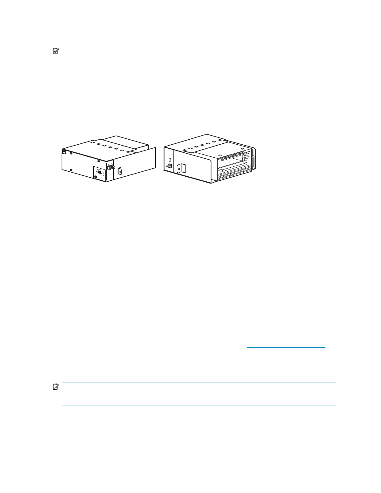
Ultrium 460, 460-FC, 960, and 1840 tape drives
The Ultrium tape drive is a high-performance streaming tape drive that uses Linear Tape-Open (LTO)
technology.
Figure 6 LTO tape drives
11598
• An Ultrium 460 or 460-FC tape drive is capable of storing up to 200 GB (native) of data per
cartridge, and has a sustained data transfer rate of up to 30 MBps (108 GBph) (native).
• An Ultrium 960 tape drive is capable of storing up to 400 G B (native) of data per car tridge, and
has a sustained data transfer rate of up to 80 MBps (native).
• An Ultrium 1840 tape drive is capable of storing up to 800 GB (native) of data per cartridge,
and has a sustained data transfer rate of up to 120 MBps (native).
Access the HP StorageWorks Ultrium Tape Drive users guide from h
information about its features and capabilities.
SDLT 320 and 600 tape drives
The SD LT tape drive is a high-capacity, high-performance streaming tape drive that uses Laser Guided
Magnetic Recording (LGMR) technology to maximize the amount of data that c an be stored on a tape.
• An SDLT 320 tape drive is capable of storing up to 160 GB (native) of data per cartridge and
has a sustained data transfer rate of 16 MBps (57.6 GBph) (native).
• AnSDLT600tapedriveiscapableofstoringupto300GB(native)ofdatapercartridgeand
has a sustained data transfer rate of 36 MBps (115.2 GBph) (native).
Access the HP StorageWorks SDLT Tape Drive Reference Guide from h
more information about its features and capabilities.
Tape cartridges
NOTE:
Tape cartridges are not include d in the purchase of a tape library. Purchase tape cartridges separately.
ttp://www.hp.com/support for more
ttp://www.hp.com/support for
HP StorageWorks
19
Page 20

Ultrium tape ca
rtridges
The Ultrium 960
and Ultrium 1840 include support for both rewriteable and Write-Once, Read-Many
(WORM) tape car tridges. WORM tape cartridges provide an enhanced level of data security
against alteration of data because you cannot erase or overwrite them. To check whether your
backup or archive software application supports WORM tape cartridges, see the following web site:
h
ttp://www.hp.com/go/connect.
For optimum performance, always use a tape cartridge that matches the specifications of your tape drive.
Table 3 on page 20 shows tape drive compatibility and tape capacity.
Table 3 Ultri
Tape drive
Ultrium 460
Ultrium 960 Read only
Ultrium
1840
1
Values assume a 2:1 compression ratio
um compatibility
Not
1
400 GB
Optimum
Read/write
Read/write Read/write Read/write
200 GB
Read/write
supported
1
800 GB
supported
Optimum Optimum
1
Not
WORM 800
1
GB
Not
supported
1600 GB
1
WORM
1600 GB
Not
supported
Not
supported
Optimum Optimum
Not
supported
Not
supported
1
NOTE:
In addition to the information provided in this manual, see the documentation provided with your media
for more information.
CAUTION:
Ultrium tape drives require special cleaning cartridges and data cartridges formatted specifically for
HP Ultrium. To avoid damage to your tape drive, it is critical to use appropriate cleaning cartridges
and properly formatted data cartridges.
Approved media has the Ultrium format trademark, which indicates the media has passed Ultrium
format compliance testing.
For best r
Librarie
esults, always use HP branded media and bar code labels. See the HP StorageWorks Tape
s Med ia and Bar Code Labels flyer for information on which media and bar code labels to
use in your tape drives.
CAUTION:
Do not bulk erase Ultrium formatted cartridges. This destroys prerecorded servo information and makes
the cart
ridge unusable.
Always visually inspect your tape cartridges when loading or removing them from your tape library.
Taking a few minutes to check the condition of your cartridges lowers the risk of repeated failures and
helps ensure uninterrupted backup.
CAUTION:
Always discard damaged tape cartridges. If a defective tape cartridge is loaded into a tape drive, it may
damage the drive, potentially requiring drive replacement.
20
Library overview
Page 21

NOTE:
For information on ordering tape cartridges and bar code labels, see the
Libraries Media and Bar Code Labels
information at h
ttp://www.hp.com/go/storagemedia
SDLT320and600tapecartridges
NOTE:
In addition to the information provided in this manual, see the documentation provided with your media
for more information.
CAUTION:
SDLT tape drives require special cleaning cartridges and data cartridges formatted specifically for SDLT.
To avoid damage to your tape drive, it is critical to use appropriate cleaning cartridges, and properly
formatted data cartridges. Do not use DLT Tape I, DLT Tape II, DLT Tape III, or DLT Tape IIIXT data
cartridges, or DLT cleaning cartridges with SDLT tape drives.
Make it a practice to visually inspect your tape cartridges when loading or removing them from your tape
library. Taking a few minutes to check the condition of your cartridges will lower the risk of repeated
failures and help ensure uninterrupted backup.
HP StorageWorks Tape
flyer that shipped with your library. You can also access this
CAUTION:
Always discard damaged tape cartridges. If a defective tape cartridge is loade d into a tape drive it may
damage the drive, potentially requiring drive replacement.
NOTE:
For informa
Libraries M
information at h
tion on ordering tape cartridges and bar code labels, see the
edia and Bar Code Labels
ttp://www.hp.com/go/storagemedia.
Load ports and magazines
The load ports are mechanical devices in the front panel of the library that enable you to import or export
tape cartridges to and from the library via three columns of tape cartridge magazines, two magazines
per column, without interrupting library operations. Removable magazines are available for both the left
and right load ports with either SDLT or LTO slots.
There are 2 tape cartridge magazines in the left load port, and 4 in the right (see Figure 7). The number of
tape ca r tridges in these magazines differs between the SDLT and LTO libraries. To find the number of tape
cartridges for any configuration, use the tables located in Library storage locations and slot numbering
HP StorageWorks Tape
flyer that shipped with your library. You can also access this
HP StorageWorks
21
Page 22

1
2
1
Left load port (16 SDLT or 18 Ultrium)
2
Rightloadport(32SDLTor36Ultrium)
Card cage and controllers
The library card cage is located in the top of the library cabinet, above cluster 0.
• The card cage holds up to six e2400-160 FC and/or e2400-FC 2G interface controllers.
• It holds a fan, and two power supplies.
• In a non-SIPP library the card cage contains the e1200-160 library robotics controller.
• In a library that contains an e2400–FC 4 G interface controller in cluster 0, the card cage houses
the Interface Manager card.
See Figure 8 for a sample card cage.
Figure 7 Lo
ad ports (left and right)
22
Library overview
Page 23
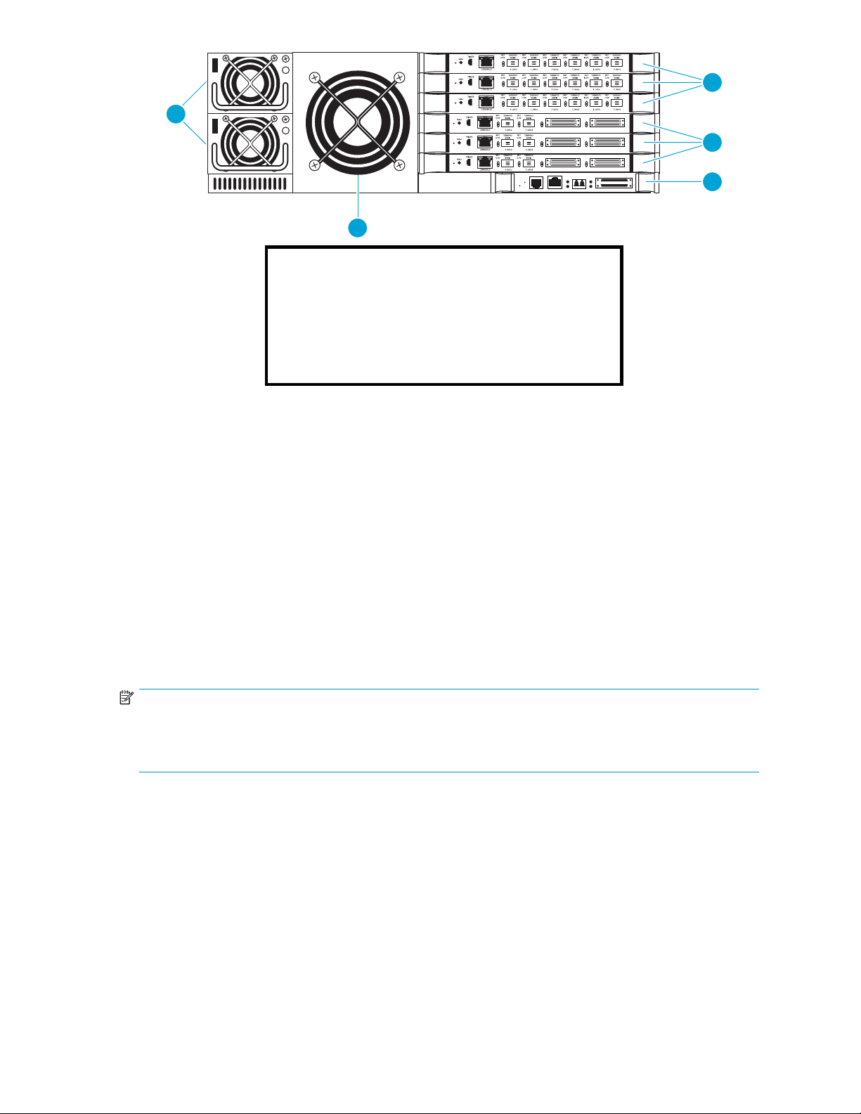
1
2
3
5
4
1
e2400-FC 2GB FC interface controllers
2
e2400-160 FC interface controllers
Library robotics controller e1200-160 (non-SIPP
3
libraries only.)
4
Card cage fa
5
Card cage power supplies
n
Figure 8 Card cage with controllers
e2400-160 FC, e2400-FC 2G, and e2400–FC 4G interface controllers
The FC inte
if necessary. It transfers commands, data, and status information to and from FC controllers and
FC and SCSI devices.
Supported
• Initiator devices – FC hosts
• Sequential access devices – tape drives
• Changer d
The e2400
Fibre Channel Switched Fabric (FC-SW) environment.
Thee2400-FC2Gand4Ginterfacecontrollersprovidefibre connectivity for native FC drives, such
as the Ult
NOTE:
For information on installing the HP StorageWorks e2400-160 FC, e2400-FC 2G, and e2400–FC 4G
interface controllers, see the
guide
rface controller translates the Fibre Channel Protocol (FCP) to and from the SCSI protocol,
devices include:
evices – tape libraries
-160 FC interface controller provides bidirectional connectivity for Ultra-3 SCSI buses in a
rium 460-FC or 960 drive.
HP StorageWorks ESL E- S eries tape library unpacking and installation
, or the documentation that shipped with the interface controller.
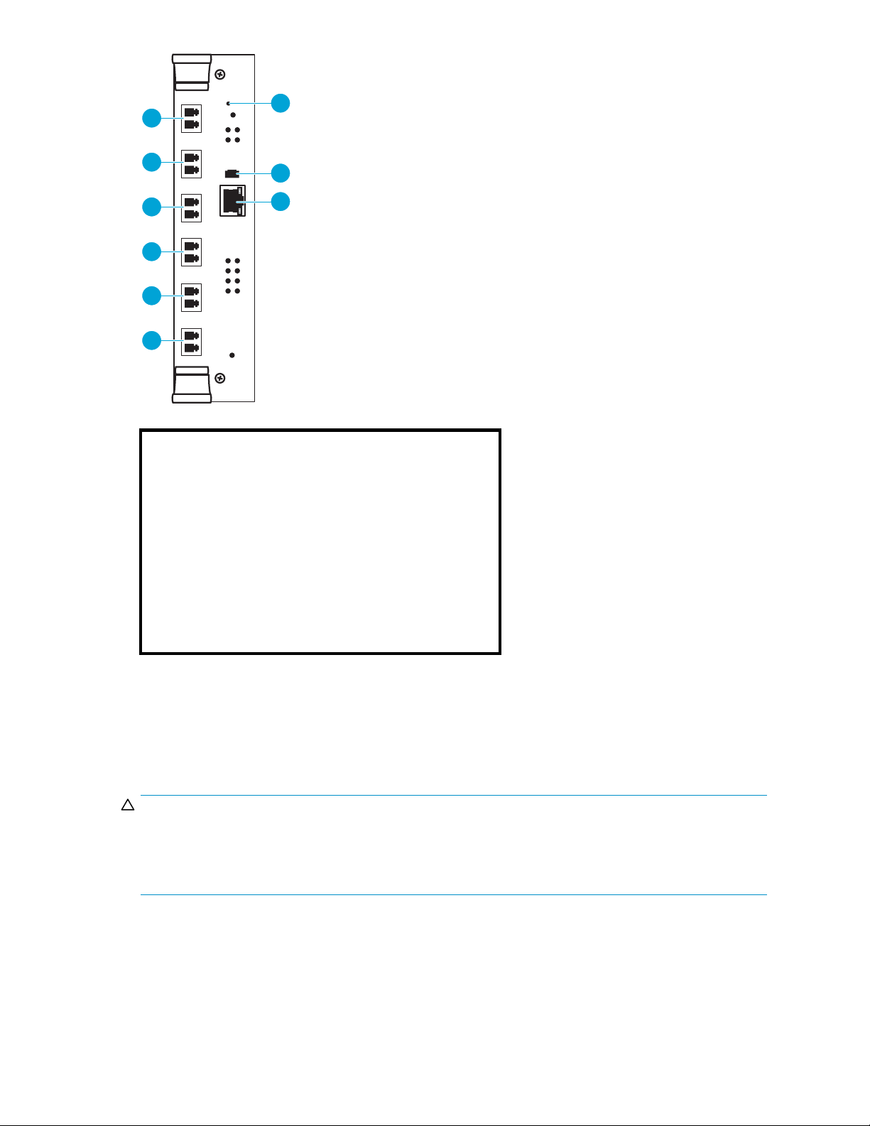
Figure 9 illustrates the I/O panel of the e2400-160 FC interface controller.
HP StorageWorks
23
Page 24

1 2 3 4 5 6 8
7 9
1
Reset button
2
Serial port
3
Ethernet por
FC port 1
4
5
FC port 2
6
SCSI bus port
7
SCSI bus port 1
8
SCSI bus port 2
9
SCSI bus port 3
t
0
Figure 9 e2400-160 FC inter fa ce controller
Figure 10 illustrates the I/O panel of the e2400-FC 2G interface controller.
1 2 3 4 5 6 7 8 9
1
Reset button
2
Serial port
3
Ethernet port
4
FC port 0 (external connection)
5
FC port 1
6
Tape drive FC port 0 (internal connection)
7
Tape drive FC port 1 (internal connection)
8
Tape drive FC port 2 (internal connection)
9
Tape drive FC port 3 (internal connection)
(external connection
Figure 10 e2400-FC 2G interface controller
Figure 11 illustrates the I/O panel of the e2400-FC 4G interface controller.
24
Library overview
Page 25
1
4
5
6
7
8
9
1
2
3
4
5
6
Reset button
Serial port
Ethernet
FC port 0 (external connection)
FC port 1 (external connection)
Tape drive F C port 0 (internal connection)
2
3
10817
port
7
8
9
Figure 11 e2400-FC 4G interface controller
Reset button
To force a manual reboot of the FC interface controller, use the reset button (see Figure 9,Figure 10,or
Figure 11). Press the button with a paper clip or other small object. You can also sele ct the Reboot menu
option in the Command View TL, as described later in this manual.
CAUTION:
Using the Reset button during an ongoing data backup, restore, or other data transfer process, can result
in a disruption of that process and a loss of data. Before selecting the Reset button, verify that no
data is currently transferring through the FC interface controller by visually i nspecting the Activity LEDs
of all I/O ports on the FC interface controller.
Power indicator
The interface controller has one power LED.
• Green - Power has been applied to this module
• Yellow - Power-On-Self-Test (POST) in process or processor problems
Tape drive F C port 1 (internal connection)
Tape drive F C port 2 (internal connection)
ive FC port 3 (internal connection)
Tape dr
HP StorageWorks
25
Page 26

Serial port
The interface co
the location of
NOTE:
The serial port is an HP service port not intended for customer use on the ESL E-Series library.
Ethernet port
One Ethernet port with an L ED indicator is included in the interface controller. See Figure 9,Figure 10,
or Figure 11 for the location of the Ethernet port.
• Activity -Portactivity
• Link - Valid Ethernet link
External FC ports
Two FC ports (for external connections) with LED indicators are found on the inter face controller: Port
F0 and Port F1. See Figure 9,Figure 10,orFigure 11 for the location of the FC ports.
• Green (ACT) - FC port activity
• Green (LINK) - Valid FC link
SCSI buses (e2400-160 FC interface controller only)
Four SCSI buses with LED indicators are included in the FC interface c ontroller. See Figure 9 for the
location of the LEDs.
• Green - SCSI bus activity on corresponding port
ntroller is equipped with one serial port. See Figure 9,Figure 10,orFigure 11 for
the serial port.
Internal FC ports (e2400-FC 2G or 4G interface controller only)
The native FC interface controller has 6 native FC ports with LED indicators: 2 ports (FC0 and FC1)
connect to the SAN; 4 ports (TD0 through TD3) connect to drives in the corresponding cluster. See
Figure 10 and Figure 11 for the location of these ports.
• Green (ACT) - FC port activity
• Green (LINK) - Valid FC link
LAN-free backup and restore
The e2400-160 FC, e2400-FC 2G, and e2400–FC 4G interface controllers can enable LAN-free
backup/restore to allow the bulk of data traffictobemovedfromtheLANtothestorageareanetwork
(SAN).
See Figure 12 foranillustrationofthisprocess.
26
Library overview
Page 27

SCSI over IP Protocol (SIPP)
Libraries can function in SIPP mode or non-SIPP mode, but not both. A library in SIPP mode looks the
same as a
absence of any e1200–160 interface controllers. The mode is recognized when the library is powered-on.
If a library is equipped with SIPP functionality, it transports SCSI commands through the interface
controller’s FC port to the library’s robotics controller Ethernet port. SIPP delivers the error handling
and retry capabilities of a TCP/IP connection.
SIPP is c
compatible with e1200–160 interface controllers. If there is more than one interface controller in the
library, the “master” interface controller receives the move c ommands. The Interface Manager assigns as
“IC SIPP Master” the first interface controller that it detects during the first boot of the library after SIPP is
enabled. Use Command View TL to find out which IC is the IC SIPP M aster.
library that is not in SIPP mode, except for the absence of the SCSI HBA and its cable, and the
ompatible with e2400–260, e2400–FC 2G, and e2400–FC 4G interface controllers. It is not
Interface Manager card
The HP StorageWorks Interface Manager is a mana gement card designed to consolidate and simplify
the management of multiple FC interface controllers i nstalled in the library. It also p rovides SAN-related
diagnostics a nd management for library compo nents including interface controllers, drives, and robotics.
The Interface Manager card, in conjunction with HP StorageWorks Command View TL software, provides
remote management of the library via a serial, telnet, or web-based graphical user interface.
In a SIPP-enabled library, the Interface Manager card is located in the bottom-most slot in the card cage;
otherwise, it is located to the right of the cluster controller in drive cluster 0
Figure 12 LAN-free backup and restore
HP StorageWorks
27
Page 28

NOTE:
Command View TL, provided with your library, is a utility that provides diagnostics and management
by accessing devices through a LAN infrastructure. For more information on Command View TL, go
to h
ttp://www.hp.com/support/cvtl.
Additional advanced SAN security and management features are available via permanent software
licenses. For more information, see the documentation that shipped with the Interface Manager and
Command View TL software kit. Details are also available at h
ttp://www.hp.com/support/cvtl.
HP StorageWorks Library and Tape Tools (L&TT) is a diagnostic utility that can access devices across a
FC infrastructure. For more information on L&TT, go to h
ttp://www.hp.com/support/tapetools.
The Interface Manager communicates with the mana gement station over the LAN. The management
station is a Microsoft® Windows-based PC (server) that hosts the Command View TL software. Ideally,
the management station should have a static IP address and be dedicated for use with the Interface
Manager and Command View TL software.
NOTE:
For information on using the Command View TL software, see the
Interface Manager and Command View TL user guide
h
ttp://www.hp.com/support/cvtl.
that shipped with your library or visit
HP StorageWorks
Any client machine on the LAN can communicate with the Interface Manager either through the graphical
user interface web interface, or through a Telnet command line interface (CLI). At a higher level, multiple
libraries, each containing an Interface Manager card, can be connected to a single management station.
Each Interface Manager card can communicate with only one manag em ent station, but the management
station can communicate with multiple Interface Manager cards (see Figure 13).
28
Library overview
Page 29
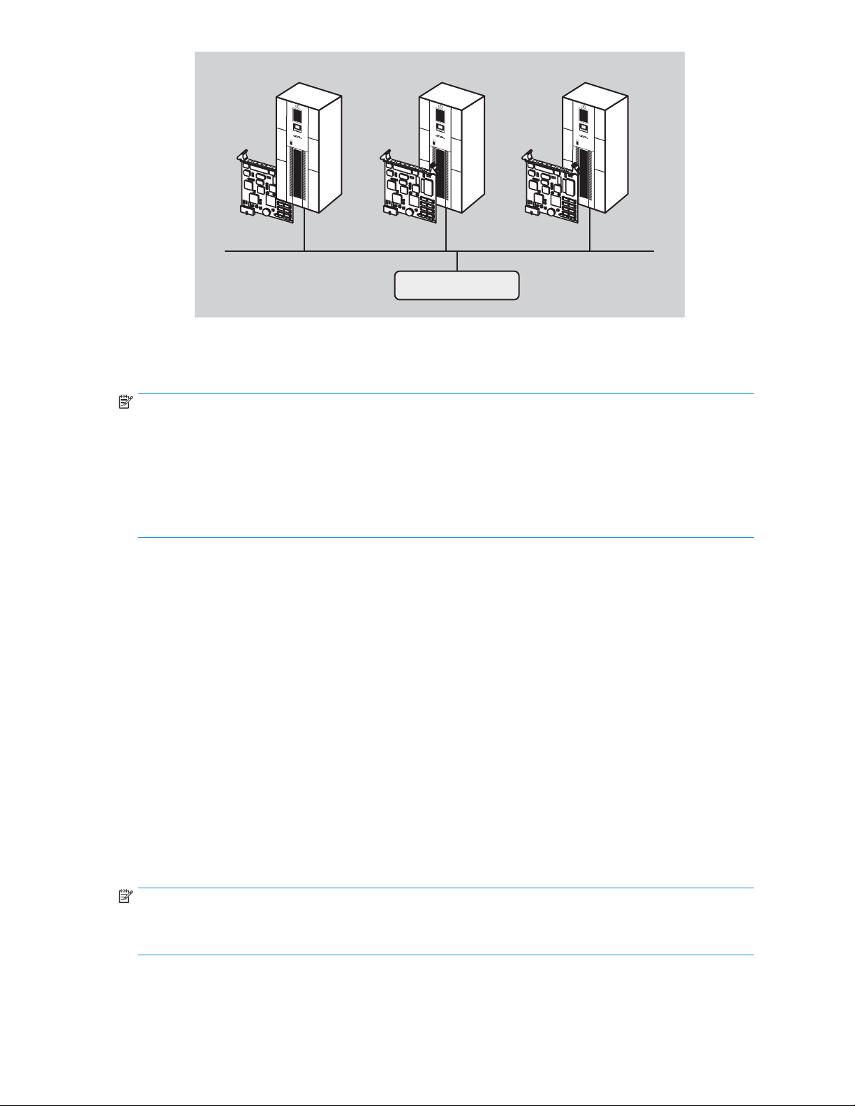
Library 1 Library 2 Library 3
10056
IP IP IP
Management Station
Figure 13 Multiple libraries connec ted to a single management station
NOTE:
IfyouarerunningCommandViewTLversion2.0orlater,youcaninstallCommandViewTLonmultiple
servers (management stations) and manage the library with more than one management station at the
same time. If you are running an earlier version of Command View TL, HP recommends that you install
Command View TL on a single dedicated server (management station) on the LAN. However, it is
possible to install Command View TL on multiple servers. In this scenario, if one management station
claims a library for management, then that same library cannot be managed by any other management
station. A library can only b e managed by one management station at a time.
Cross Linked libraries
A Cross Linked library is two to five library cabinets joined together by hardware, software, and firmware
to function as a single high-capacity library. The Cross Link Kit connects a designated primary cabinet
with another cabinet, which is called a secondary cabinet. Each Cross Link Expansion kit connects
another secondary cabinet to the system. The entire system is then referred to as a library. Specific
differences between primary and secondar y cabinets are explained in this section.
Cross Link cabinets functionality
The primary cabinet controls the robotics of the secondar y cabinets. The primary cabinet functions much
like a normal tape library, but it also retrieves data tapes from, sends data tapes to, and assigns storage
locations in the secondary cabinets. To do this, the OCP of a primary cabinet has functionality in
addition to that of a standalone library.
Secondary cabinets function mainly as storage units for the Cross Linked library. Their robotics are
controlled by the primary cabinet. Secondary cabinets have very limited options on the OCP.
OCPs for all three types of cabinets (standalone, primary, and secondar y) are presented in Operator
control panel (OCP).
NOTE:
In all other ways, the Cross Linked library has the same capabilities as a standalone system. Any
differences in the operation of a Cross Linked library are noted in this guide.
HP StorageWorks
29
Page 30

Space requirem
In addition to the space required for standalone libraries, a CLM library requires 52 inches (130 cm)
of clear space t
called Floor space in HP StorageWorks ESL E-Series Tape Library unpacking and installation guide
for further information.
ents
System components
NOTE:
TheprimarycabinetofaCrossLinkedLibrarymustbeanESL712eor630e,oranESL322eor286e
that has already been expanded to full capacity using purchased licenses installed using Command
View TL. Secondary cabinets must be ESL 712e or 630e libraries.
The primary cabinet must have between 1 and 5 fully-populated clusters (that is, each of these clusters
must contain 4 drives). Cabinet 2 in the library must have at least 1 drive cluster containing at least 1
drive, and may have up to 6 fully-populated clusters. Other secondary cabinets must have at least 1 drive
cluster containing at least 1 drive, and may have up to 2 fully-populated drive clusters. The entire library
can have up to 11 clusters and up to 44 drives. Maximum slot count in a 5 cabinet library is 3,560.
Cross Linked systems contain the following additional parts:
• Cross Link arm (CLM arm)
• Cross Link robotics controller (CLM robotics controller)
The CLM arm (see Figure 14) is used to send a shuttle between libraries. The shuttle carries a data tape
cartridge so that it can be stored in a secondary cabinet or retrieved for use, as necessary.
o the left of the primary cabinet as you face the front of the cabinets. See the section
10667
Figure 14 CLM arm
The CLM robotics controller (see Figure 15) is located on the primary library only, just above the cabinet
controller. In an individual library, this would be considered the number 5 drive bay. The controller
contains the power supplies, CLM electronics PWA, and Ethernet hub for the CLM robotics. It supplies
power to and controls the CLM.
30
Library overview
Page 31

10664
Figure 15 CLM robotics controller
The CLM sensor board (see Figure 16) is located near the CLM motor assembly, at the far right of the
CLM arm (in the primary cabinet) as you face the back of the libraries. It contains a spring loaded sensor
assembly which detects the CLM shuttle when it is in the home position.
1
10665
1
#1 Phillips screws
6 CLM sensor board
The CLM m
of the ca
binets. The CLM arm runs along the top of the back of the cabinets. The CLM motor assembly is
Figure 1
otor assembly (see Figure 17) is located on the far right of the CLM arm as you face the back
a single motor with a pulley that drives the CLM shuttle.
HP StorageWorks
31
Page 32

Lock Element Addressing
10636
Figure 17 CLM motor assembly
Lock Eleme
Lock Eleme
drives, h
feature i
To enable or disable Lock Element Addressing:
1. From the OCP of the primary cabinet, select Menu,thenSetup.
2. From the Setup screen, select Lock Element Addressing.
3. Use the U
Disable
drives
nt Addressing should be used on a CLM library with 3 or more cabinets. When enabled,
nt Addressing ensures that if a secondary cabinet goes off-line, locations and counts of
osts, and all other elements in the remaining cabinets stay the same. If a cabinet fails when this
s disabled, these elements will likely change.
p and Down arrows to highlight Enabled or Disabled,thepressSelect.
Lock Element Addressing in order to change locked elements such as load ports, number of
,ornumberofcabinets.
Library storage locations and slot numbering
The HP StorageWorks ESL E-Series standalone tape library is an automated tape storage and retrieval
library that may consist of up to 24 tape drives and up to 718 Ultrium tape cartridges, or 636 SDLT tape
cartridges, or a combination of Ultrium and SDLT tape cartridges in a mixed-media system.
NOTE:
CLM libraries have different storage capacities and requirements depending on how many cabinets are
in the library, among other considerations. Due to the number of variations possible, slot numbering
for CLM libraries is not provided. The panel and general slot information presented here does apply
to each cabinet within a CLM library.
The library stores tape cartridges in the following locations:
• Left panels
• Right panels
• Back panels
32
Library overview
Page 33

NOTE:
The number of tape cartridge slots depends on the drive technology used and, on a mixed-media system,
on the ratio of Ultrium and SDLT panels used and their locations. The number of back panel slots
depends on how many drive clusters are in the library. See SDLT library,andMixed media library for
tape cartridge quantity information.
To slide the slot panels out of the cabinet, press the slot panel latches down and pull the slot panel out of
the cabinet (see Figure 18).
1
2
3
1
Upper load port panel latch
2
Middle load port panel latch
3
Lower load port panel latch
Figure 18 Sliding the slot panels out of the cabinet
Figure 19 shows the left panel bins. Begin with panel 1 and load top to bottom and left to right. Continue
with panel 2 in the same manner, and finally, panel 3.
HP StorageWorks
33
Page 34

1
2
3
1
Panel 1
2
Panel 2
3
Panel 3
Figure 19 Bin shelf numbering, left panels
Figure 20 shows the right panel bins. Begin with panel 4 and load top to bot tom and left to right.
Continue with panel 5 in the same manner, and finally, panel 6.
34
Library overview
Page 35

1
2
3
1
Panel 4
2
Panel 5
3
Panel 6
Figure 20 Bin shelf numbering, right panels
21 shows the back panel bins. Each column has seven slots. Begin at the top, with the panel
Figure
ponding to cluster 0, and load top to bottom and left to right. Continue loading each sequential
corres
er, top to bottom and left to right.
clust
NOTE:
The number of slots located in the back panel varies with the number of drive clusters installed.
HP StorageWorks
35
Page 36

1
2
NOTE:
Upgrade capacity in ESL-E 322e and ESL-E 286e partial capacity units by activating one or more
panels. For more information, see the
guide
that shipped with your library or visit http://www.hp.com/support/cvtl.
Ultrium library
Table 4 shows storage capacity in Ultrium-only, standalone libraries with removable magazines.
1
Cluster 0
2
Back panel bins
Figure 21 Bin shelf n u m b ering, back panel
HP StorageWorks Interface Manager and Command View TL user
36
Library overview
Page 37

Table 4 Ultrium library storage elements (removable magazines)
Number of drives
1–4
1–4
1–4
1–4
5–8 0 0 698
5–8
5–8
5–8
9–12 0 0
9–12
9–12
9–12
13–16 0 0 670
13–16
13–16
13–16
17–20 0 0 656
Load ports used Load port capacity User slots
00712
Left only
Right only
Both
Left only
Right only
Both
Left only
Right only
Both
Left only
Right only
Both
16 696
32 680
48 664
16 682
32 666
48
16 668
32 652
48
16
32 638
48
650
684
636
654
622
17–20
17–20
17–20
21-24
21-24
21-24
21-24
Left only
Right only
Both
00
Left only
Right only
Both
16
32
48
16 626
32 610
48 594
640
624
608
642
NOTE:
Slots in e
nabled load ports cannot be used as data slots.
Table 5 shows storage capacity in Ultrium-only, standalone libraries with fixed magazines.
HP StorageWorks
37
Page 38

Table 5 Ultrium library storage elements (fixed magazines)
Number of drives
1–4
1–4
1–4
1–4
5–8 0 0 704
5–8
5–8
5–8
9–12 0 0 690
9–12
9–12
9–12
13–16 0 0 676
13–16
13–16
13–16
17–20 0 0 662
Load ports used Load port capacity User slots
00718
Left only
Right only
Both
Left only
Right only
Both
Left only
Right only
Both
Left only
Right only
Both
18 700
36 682
54 664
18 686
36 668
54
18 672
36
54
18 658
36
54
650
654
636
640
622
17–20
17–20
17–20
21-24
21-24
21-24
21-24
NOTE:
Slots in e
SDLT library
Table 6 shows storage capacity in an SDLT-only, standalone library with removable magazines.
Left only
Right only
Both
00
Left only
Right only
Both
18
36 626
54
18 630
36 612
54 594
nabled load ports cannot be used as data slots.
644
608
648
38
Library overview
Page 39

Table 6 SDLT library storage elements (removable magazines)
Number of drives
1–4
1–4
1–4
1–4
5–8 0 0 618
5–8
5–8
5–8
9–12 0 0 606
9–12
9–12
9–12
13–16 0 0
13–16
13–16
13–16
17–20 0 0 582
Load ports used Load port capacity User slots
00630
Left only
Right only
Both
Left only
Right only
Both
Left only
Right only
Both
Left only
Right only
Both
14
28 602
42
14 604
28 590
42
18 592
28 578
42 564
18 580
28 566
42
616
588
576
594
552
17–20
17–20
17–20
21-24
21-24
21-24
21-24
Left only
Right only
Both
00570
Left only
Right only
Both
18 568
28
42 540
18 556
28
42
554
542
528
NOTE:
Slots in e
nabled load ports cannot be used as data slots.
Table 7 shows storage capacity in an SDLT-only, standalone library with fixed magazines.
HP StorageWorks
39
Page 40

Table 7 SDLT library storage elements (fixed magazines)
Number of drives
1–4
1–4
1–4
1–4
5–8 0 0 624
5–8
5–8
5–8
9–12 0 0 612
9–12
9–12
9–12
13–16 0 0 600
13–16
13–16
13–16
17–20 0 0 588
Load ports used Load port capacity User slots
00636
Left only
Right only
Both
Left only
Right only
Both
Left only
Right only
Both
Left only
Right only
Both
16 620
32
48
16 608
32 592
48
16 596
32 580
48 564
16
32 568
48
604
588
576
584
552
17–20
17–20
17–20
21-24
21-24
21-24
21-24
NOTE:
Slots in e
nabled load ports cannot be used as data slots.
Mixed media library
An Ultrium or SDLT library at firmware level 2.0 or greater, can be converted into a mixed-media library
by exchanging existing panel 1; panels 1 and 2; or panels 1, 2, and 3 for the type of media panel not
yet in the library. Mixed-media libraries require library partitioning, with one media type per partition.
See HP StorageWorks Interface Manager and Command View TL users guide to learn about and use
library partitioning. Removable magazines are also required in a mixed-media library.
These requirements impact library operations in the following ways:
• If you convert panel 1 only to a new media type, neither load port ca n be used to insert or
remove media from that p anel. Because the left and right load ports are on panels 2 and 5, they
musthavethesamemediatypeastherestofpanels2and5.
Left only
Right only
Both
00576
Left only
Right only
Both
16 572
32 556
48 540
16 560
32
48
544
528
40
Library overview
Page 41

• If panels 1 and 2 (or 1, 2, and 3) are converted to a new media type, the left load port can
be used to insert or remove media from the converted panels. The right load port is used to
insert or remove media from the existing panels.
• The type of media added to your library is on the left side of the library only; therefore, the
additional media type has only one column of load port capacity, and the existing media type
hastwocolumnsofloadportcapacity.
These are important when determining the library storage capacity. Storage capacity in a mixed-media
library depends on the quantity of panels exchanged, the location of media t ypes you are using, whether
the load ports are enabled, and the number of drives in the library.
NOTE:
In order to use mixed media, the library must be at firmware revision level 2.0 or greater . Update the
firmware before installing mixed media in the library.
HP StorageWorks
41
Page 42

42
Library overview
Page 43

2 Library opera tions
This chapter describes the basic library operating procedures in:
• Taking ESD precautions
• Preparing tape cartridges
• Inser ting tape cartridges
• Closing the cabinet doors and access pa nels
• Powering the library on and off
•UsingtheOCP
• Inserting tape cartridges into a fixedloadport
• Using removable magazines
Taking ESD precautions
Components
performin
WARNING!
This product can only be used with an HP approved power cord for your specificgeographicregion.
Use of a non-HP approved power cord may result in: 1) not meeting individual country specificsafety
requirements; 2) insufficient conductor ampacity that could result in overheating with potential personal
injury and/or property damage; and 3) fracturing resulting in the internal contacts being exposed,
which potentially could subject the user to a shock hazard. HP disclaims all liability in the event a
non-HP a
• Keep the cabinet turned off during all installation, m a intenance, and replacement procedures.
• Keep the cabinet power cord c onnected to a grounded power outlet except when working with
AC electrical components.
within the library contain static-sensitive parts. To prevent damage to these parts while
g installation, maintenance, or replacement procedures, observe the following precautions:
pproved power cord is used.
ce produit ne peut être utilisé qu'avec un cordon
AVERTISSEMENT :
d'alimentation approuvé par HP pour votre zone géographique. L'emploi
d'un cordon d'alimentation non approuvé par HP peut avoir les conséquences
suivantes : 1) non-conformité aux spécifications de sécurité du pays concerné ;
2) intensité admissible du conducteur insuffisante pouvant provoquer une
surchauffe créant un risque de blessure ou d'endommagement du produit ;
et 3) rupture pouvant exposer les contacts internes et créer un risque
d'électrocution pour l'utilisateur. HP décline toute responsabilité en cas
d'utilisation d'un cordon d'alimentation non approuvé.
Dieses Produkt kann ausschließlich mit einem von HP für Ihre Region
VORSICHT:
zugelassenen Netzkabel verwendet werden. Die Verwendung eines nicht
von HP zugelassenen Netzkabels kann folgende Konsequenzen haben:
1) Nichteinhaltung der nationalen Sicherheitsbestimmungen, 2) Überschreiten
der Strombelastbarkeit des Netzkabels, was zu einer Überhitzung und in der
Folge zu Verletzungen und Sachschäden führen kann, 3) Stromschlaggefahr
durch Kabelbruch und Freilegen der Adern. Für den Fall, dass ein nicht von HP
zugelassenes Netzkabel verwendet wird, übernimmt HP keinerlei Haftung.
HP StorageWorks
43
Page 44

Il presente prodotto può essere utilizzato esclusivamente con
AVVERTENZA:
un cavo di alimentazione approvato da HP specifico per la regione geografica
dell'utente. L'utilizzo di un cavo di alimentazione non approvato da HP
potrebbe comportare: 1) la non conformità alle normative locali in materia di
antinfortunistica; 2) l'insufficienza della capacità di amperaggio del conduttore
con conseguente surriscaldamento e potenziali lesioni personali e/o danni alla
proprietà; 3) la rottura del prodotto con conseguente esposizione dei contatti
interni e potenziali lesioni da scosse. HP rifiuta ogni responsabilità in caso di
utilizzo di un cavo di alimentazione non approvato da HP.
Dit product mag ALLEEN worden gebruikt met een netsnoer
WAARSCHUWING:
dat door HP is goedgekeurd voor gebruik in uw regio. Als u een netsnoer
gebruikt dat niet door HP is goedgekeurd, kan dit ertoe leiden dat: 1) u niet
voldoet aan de specifieke veiligheidsvoorschriften van uw land, 2) de aderdikte
te klein is, waardoor oververhitting kan optreden met lichamelijk letsel en/of
beschadiging van de apparatuur tot gevolg, en 3) het netsnoer breekt, waardoor
de interne contacten bloot komen te liggen met het risico van letsel door
elektrische schok. HP wijst alle aansprakelijkheid af als u een netsnoer gebruikt
dat niet door HP is goedgekeurd.
ADVERTENCIA: este producto sólo puede utilizarse con un cable de
alimentación aprobado por HP para su región geográfica específica.
El uso de un cable de alimentación no aprobado por HP puede provocar
lo siguiente: 1) el incumplimiento de requisitos de seguridad específicos del país;
2) insuficiente corriente permanente admisible de conductor que puede provocar
un sobrecalentamiento y posibles lesiones personales o daños a la propiedad;
y 3) una rotura que deje expuestos los contactos internos, lo que supone
un peligro potencial de descarga eléctrica para el usuario. HP renuncia a
toda responsabilidad en caso de utilizarse un cable de alimentación no
aprobado por HP.
WARNING!
Avoid contact with the power supplies, EMI filter, and all other AC electrical components while the
cabinet is connected to a power outlet.
évitez tout contact avec les blocs d'alimentation, le filtre EMI
AVERTISSEMENT :
et tous les autres composants électriques CA pendant que l'armoire est connectée
à une prise de courant.
Wenn der Schrank an das Stromnetz angeschlossen ist, dürfen
VORSICHT:
keinesfalls Netzteile, EMI-Filter oder andere elektrische Komponenten berührt
werden.
44
Library operations
Page 45

Evitare il contatto con alimentatori, filtri EMI e qualsiasi altro
AVVERTENZA:
componente elettrico AC quando il cabinet è collegato a una presa di corrente.
Raak de voedingseenheden, het EMI-filter en de andere
WAARSCHUWING:
elektrische onderdelen niet aan als kast is aangesloten op een stopcontact.
• Use an antistatic wrist strap when touching internal cabinet components. To use the wrist strap
properly, place the band around your wrist and attach the clip to the cabinet frame. Keep the
strap on until you are ready to close the cabinet doors.
• Keep static-sensitive parts in their ship ping containers until ready for installation.
• Do not place static-sensitive parts on any metal surface. If you need to put down a static-sensitive
part, place it inside its protective shipping bag or on a grounded a ntistatic mat.
• Avoid direct contact with static-sensitive parts. Avoid touching connectors and discrete
components.
• Close cabinet door and access panel when not working on the cabinet.
• Be careful when installing the cabinet or handling components in dry climates or environments
where cold weather heating is used. Environments such as these with lower relative humidity have
greater potential to produce static electricity.
NOTE:
In environments with high potential for static electricity, take additional precautions, such as the use of
an antistatic smock or a grounded antistatic mat.
Preparing tape cartridges
CAUTION:
Handle tape cartridges with care. Do not drop or mishandle them, or place them near sources of
electromagnetic interference. Rough handling can da mage the cartridge, making it unusable and
potentially hazardous to the tape drives.
Labeling tape cartridges
CAUTION
The misu
To ensur
supplierandneverprintbarcodelabelsyourself. Formoreinformation,seetheorderformprovided
with the library, as well as the
available from h
NOTE:
For information on ordering tape cartridges and bar code labels, see the ordering sheet that shipped
with your library.
:
se and misunderstanding of bar code technology can result in backup and restore failures.
e that your bar codes meet HP’s quality standards, always purchase them from an approved
Bar Code Label Requirements, Compatibility and Usage
ttp://www.hp.com/support.
white paper
HP StorageWorks
45
Page 46

Attaching a bar code label to each tape cartridge enables the library and application software to
identify the cartridge quickly, thereby speeding up inventory time. Make it a practice to use bar
code labels on your tape cartridges. Your host software may need to keep track of the following
information and the associated bar code:
• Date of format or initialization
• Tape’s media pool
• Data residing on the tape
• Age of the backup
• Errors encountered while using the tape (to determine if the tape is faulty)
NOTE:
If you have more than 100 unlabeled tape cartridges, your library will hang during inventory or
when you power on the library. When this happens, Going on line displays in the OCP.
Ultrium bar code labels
Ultrium cartridges have a recessed area located on the face of the cartridge next to the write-protect
switch. Use this area for attaching the adhesive-backed ba r code label (see Figure 22). Do not apply
labels onto the cartridge except in this designated area.
CAUTION:
The bar code label should be applied as s hown in Figure 25, with the alphanumeric portion facing
the hub side of the cartridge. N ever apply multiple labels onto a cartridge, because extra labels can
cause the cartridge to jam inside a tape drive.
0 0 0 2 2 0 L3
0 0 0 2 2 0 L4
11657
Figure 22 Attaching an Ultrium bar code label
For successful operation of your tape library, p lace the bar code label entirely within the recessed area,
ensuring that no part of the label is outside of it (see Figure 23).
46
Library operations
Page 47

SDLT bar code labels
SDLTcartridgeshaveafrontslideslotlocatedonthefaceofthecartridgenexttothewrite-protectswitch
(see Figure 24). Inserting the bar code label by sliding it into the slot.
CAUTION:
Do not apply labels to the top, bottom, sides, or back of the cartridge as this may cause damage to the
tape drive, or interfere with reliable operation.
Figure 23 Proper Ultrium bar code label pla cement
HP StorageWorks
47
Page 48

Media label identifiers
Be sure to use the proper bar code labels for your drive technology. Table 8 lists the identifier that is
found at the end of 7- or 8-character SDLT and Ultrium bar code labels.
CAUTION:
To ensure that your bar codes meet HP’s quality standards, always purchase them from an approved
supplierandneverprintbarcodelabelsyourself. Formoreinformation,seetheorderformprovided
with the library, as well as the
available from h
Table 8 Media label identifiers
1
Barcode la
2
Orange window
3
Write-protect—slide left
4
Write enabled (default)—slide right
5Insertionarrow
bel
Figure 24 Inserting an SDLT bar code label
Bar Code Label Requirements, Compatibility and Usage
ttp://www.hp.com/support.
white paper
Cartridge type
SDLT
SDLT
SDLT 600
Ultrium 230
Ultrium 460
Ultrium 960 400/800 GB
Ultrium 1840
48
Library operations
Capacity
110/220 GB
160/320 GB
300/600 GB
100/200 GB
200/400 GB
800GB/1.6TB
Label identifier
SorS1
SorS2
2
L1
L2
L3
L4
Page 49

Setting the writ
e-protect switch
Each tape cartridge has a sliding write-protect switch. This switch determines whether new data can
be written to the tape cartridge (write-enabled) or whether da ta on the tape cartridge is protected
from being erased or overwritten (write-protected).
Write-protecting Ultrium tape cartridges
By moving the switch to the left (Figure 25), the tape cartridge is write-enabled. By moving the switch to
the right, the tape cartridge is write-protected.
1
3
1
Write enabled
2
Write protected
3
Write pro
4
Bar code label
5Insertionarrow
Figure 25
Write-protecting SDLT tape cartridges
2
4
tect switch
5
Write-protecting U l trium tape cartridges
By moving the switch to the left (Figure 26), the tape cartridge is write-protected (orange indicator is
visible). By moving the switch to the right, the tape cartridge is write-enabled (orange indicator is not
visible).
HP StorageWorks
49
Page 50

1
Barcode la
2
Orange window
3
Write-protect—slide left
4
Write enabled (default)—slide right
5Insertionarrow
Figure 26 Write-protecting SDLT tape cartridges
bel
Inserting tape cartridges
Load tape cartridges into the library starting with the left side panels, then the right side panels, and finally
the back panel (see Library storage locations and slot numbering for detailed installation procedures). Be
sure all cartridges are properly positioned with the barcode facing you and fully seated in the bins.
CAUTION:
Handle tape cartridges with care. Do not drop or bang them, or place them near sources of
electromagnetic interference. Rough handling can displace the tape leader, making the cartridge
unusable and p otentially hazardous to the tape drives.
Closing the cabinet doors and access panels
The library has two front doors and one back door.
1. Close and lock the front door using the key provided in the accessory kit (see Figure 27).
50
Library operations
Page 51

1
2
2
1
Front door latch
2
Power button
Figure 27 Closing the front door
2. Closeandlockthebackdoorusingthekeyprovidedintheaccessorykit(seeFigure 28).
1
1
Back door
2
Back door latch
Figure 28 Cl osin g the bac k door
Powering the library on and off
scussion contains:
This di
• Powering on the library
• Placingthelibraryon-lineoroff-line
•Power
Po wering on the library
To power on the library:
1. Verify that power cables are firmly in place.
2. Open the back door of the library cabinet and flip the breaker switches to the on position (right).
3. Close all library doors.
ing off the library
The breaker switches are on the power distribution unit located on the bottom right side of the
library cabinet.
HP StorageWorks
51
Page 52

4. Power on the power switch (see Figure 27).
NOTE:
The library requires several minutes to power on. Nothing displays on the OCP for the
firstfewminutesofthisprocess.
Placing the library on-line or off-line
To place the library on- or off-line:
1. With the library powered on, p ress the Ops button on the OCP to access the Operations screen.
2. Select Ca binet and use the Up and Down arrows to take the library off-line or place it on-line.
For more information on the Operations screen, see Operations screen.
Powering off the library
To power off the library:
1. Place the library off-line, see Placing the library on-line or off-line.
The library robotics completes any current commands and then stops.
2. Verify that the OCP display indicates “Off-line” from the Operations screen.
3. Verify that the media picker is empty.
4. Verify that no backups are in process.
5. Turn off the power switch located on the front of the library (see Figure 27).
6. Wait for the library to complete the shutdown process. (This usually takes 30 seconds, but may
take up to two minutes.)
7. Open the back door of the library cabinet and flip the breaker switches to the off position (left).
The breaker switches are on the power distribution unit located on the bottom left side of the
library cabinet.
NOTE:
When powering off the library, ensure that the two breaker switches on the power
distribution unit are in the off (left) p osition.
Using the OCP
The OCP is located on the front of the library. The menus on the OCP a llow you to obtain information
about the library, execute library commands, and test library functions.
The status bar at the top of the OCP displays library status at all times, at the left of the bar. The status
can be Online, Going Online,orOffline, followed by a warning level: OK, Warning, or Critical.
In addition, when a library firmware upgrade is in progress, Upgrading FW is displayed on the right
side of the status bar.
NOTE:
If the library reports a status of Warning or Critical, check the Health Status screen to see which
component is causing that status. See Viewing library health status information (standalone libraries
only) for details.
52
Library operations
Page 53

NOTE:
For Cross Linked systems, there will be different O C P menu options for the primary and secondary
cabinets in the system. The sections below present information for a standa lone library, the primary
cabinetinaCrossLinkedsystem,andthesecondarycabinetsinaCrossLinkedsystem.
Before using the OCP to perform library functions, familiarize yourself with:
• H ome screen
•OCPbuttons
Home screen
The first screen the O CP displays after library initialization is the home screen. This screen displays
library status and provides information on the IP address, number of bins, tape drives, ports, and date
(see Figure 29, Figure 30,andFigure 31).
HP StorageWorks
53
Page 54

Menu Ports Ops Diags STOP
10646
Figure 29 Home screen on standalone library
10642
Figure 30 Home screen on primary library
OCP buttons
At the
the five push buttons below the OCP. To select a function, press the push button directly below the
button label on the OCP screen.
54
10666
Figure 31 Home screen on secondary library
bottom of each OCP screen are up to five button labels. These labels indicate the functions of
Library operations
Page 55

OCP components
The OCP allows yo
functionality available from the Home screen of a standalone library or the Primary cabinet of a Cross
Linked library (see Figure 29).
u to perform various functions on the library. Table 9 provides a list of the OCP
HP StorageWorks
55
Page 56

Table 9 OCP components for a standalone library or the primary cabinet of a Cross
Linked system
Screen
Home
Menu
Ports
Ops Operations
Displays Options to view or select
Status
Menu items
Load Ports
Library Name, Date, Model Number, IP Address,
Configured Slots, Configured Drives, Ports, Partitioned
(primary only), Library State
Library, Cabinet, Health Status, Partitions (primary only),
Setup, Service, Event Log
Open Left Load Port, Open Right Load Port, Open Both
Load Ports
Library (primary only)
• Online
• Inventory Reboot
• Offline
Cabinet
• Online
• Offline
• Inventory
• Reboot (standalone only)
• Details
CLM (primary only)
• Details
• Reboot
Move Media
• Source Type
• Source Position
• Destination Type
• Destination Position
• Perform Move Now
Drive All
• Reset
• Unthread
• On
• Off
Drive #
• Details
• Reset
• Unthread
• On
• Off
botics Self Test, I ndividual Axis Self Test, Robotics to
Ro
ome Position, Calibrate Cabinet, Read Cabinet Serial
H
umbers, Read Cabinet IEEE Id, Read Cabinet Type, CLM
Diags
Diagnostics
N
elf Test (primary only), CLM to Home Position (primary
S
only), Sequential Slot Test, Sequential Drive Test, Random
Test, Random Slot Test, Random Slot to Drive Test, Element
to Element Test
Table 10 provides a list of the OCP functionality available from the Home screen of a standalone library
or the Primary cabinet of a Cross Linked library (see Figure 31).
56
Library operations
Page 57

Table 10 OCP components for a secondary cabinet of a Cross Linked system
Screen
Home
Menu
Ports
Ops Operation
Displays Options to view or select
Status
Menu items
Load Ports
Library Name, D
Drives, Ports
Cabinet,HealthStatus,Setup,EventLog
Open Left Load Port, Open Right Load Port, Open Both
Load Ports
Cabinet
• Online
• Offline
• Details
• Inventory
Drive All
• Reset
s
• Unthread
• On
• Off
Drive #
• Details
• Reset
• Unthrea
• On
• Off
ate, Model Number, IP Address, Slots,
d
Diags
NOTE:
The STOP button located in the bottom right-hand portion of the OCP is available from every OCP
screen. This button stops the cabinet robot from moving and takes the cabinet offline. To start the robotics
and re
The following sections provide information on each function available from the library OCP:
•Menuscreen
• Load Ports screen
•Operationsscreen
• D iagnostics screen
• Stop button
Menu screen
The Menu screen provides access to contact and cabinet information, as well as providing a way
to setup library information.
To access the Menu screen, press Menu from the Home screen. The OCP displays the Menu screen
(see Figure 32):
Diagnostics
Robotics Self Test, Individual Axis Self Test, Robotics to
Home Position, Calibrate Cabinet, Read Cabinet Serial
Number, Read Cabinet IEEE Id, Read Cabinet Type
turn the cabinet to the online state, press the Start button.
HP StorageWorks
57
Page 58

10389
Figure 32 Menu screen
The Menu screen provides choices detailed in:
• Viewing library information (standalone libraries or primary cabinets only) This is not available
on secondary cabinets of Cross Linked systems
• Viewing cabinet information
• Viewing library health status information (standalone libraries only)
• Viewing and editing setup information
• Viewing the library service menu (for service personnel only)
•Viewingtheeventlog
Viewing library information (standalon e libraries or primary cabinets only)
To view library information:
1. From the M
The Library screen displays (see Figure 33).
enu screen, use the Up and Down arrows to highlight Library,thenpressSelect.
58
Library operations
Page 59

10640a
Figure 33 Library screen (standalone only)
10640a
Figure 34 Library screen (primary only)
The Library screen displays the following information about the library:
• Software - software version currently loaded on the library
• Cabinet Contr - the firmware revision on the cabinet controller smart media
• Cabinet Robot - the firmware revision on the robotics controller smart media
• Serial Number - serial number of the library
• IEEE ID - internal network identification of the cabinet that includes the date of manufacture,
product type, and serial number
• Drives - shows the total number of drives for all cabinets combined (primary cabinet only)
• Slots - shows the total number of slots for all cabinets combined (primary cabinet only)
• Ports - shows the total number of ports for all cabinets combined (primary cabinet only)
2. When you are finished viewing library information, press Back to return to the Menu screen.
ng cabinet information
Viewi
w library cabinet information:
To vie
1. From the Menu screen, use the Up and Down arrows to highlight Cabinet,thenpressSelect to display
the Cabinet screen (see Figure 35):
HP StorageWorks
59
Page 60

Figure 35 Cabinet screen
The Cabinet screen displays the following information about the library cabinet:
• Cabinet - name of the cabinet
• M odel - model number of the cabinet
• Serial Number - serial number of the cabinet
• I EEE ID - internal network identification of the cabinet that includes the date of manufacture,
product type, and serial number
• Slots - number of slots configured in the cabinet
• Drives - number of drives configured in the cabinet
• Load Ports - number of load port slots configured in the cabinet
2. When you are finished viewing cabinet information, press Back to return to the Menu screen.
Viewing library health status information (standalone libraries only)
The Health Status screen captures current information about any errors present at the time Health Status is
d. Information about sensors with state of Down, Warning, or Critical is displayed, along with
selecte
informa
NOTE:
Library status is continually displayed on the left side of the black bar at the top of the OCP. Possible
status messages are: Online, OK; Online, Warning; and Online, Critical. When multiple errors exist, the
mostseriousstatusisreported. TheHealth Status screen is useful when the status bar shows warning
or crit
tion on any drives with Load Error, Not communicating, Cleaning requested, or Cleaning required.
ical status.
10648
To view the health status of the library:
1. From the Menu screen, use the Up and Down arrows to highlight Health Status then press Select.
2. If you are performing this task from the primary cabinet of a Cross Linked system, select the
appropriateCabinet#fromthelistdisplayed.
If there are no errors, the following Health Status screen displays (see Figure 36).
60
Library operations
Page 61

Figure 36 Health Status screen when no errors exist
If there are errors, present, they will be listed on the screen.
3. When you are finished viewing the error information, press Back to return to the Menu screen.
NOTE:
The Health Status information is not saved. When you exit this screen, the information is
gone.
Viewing partition (Lock Element Addressing) information
NOTE:
Although when Lock Element Addressing is enabled, some OCP screens show this as “Partitioned”,
this is not the same as HP library p artitioning.
To view information on the locked elements:
1. From the Menu screen, use the Up and Down arrows to highlight Partitions,thenpressSelec t.
2. From the Partition screen, which says “hpLibrary”, press the Down arrow once, then press Select.
3. Use the Back button to return to the home screen.
10496
Viewing
and editing setup information
To view o
1. From the Menu screen, use the Up and Down arrows to highlight Setup,thenpressSelect.
2. The library prompts you for your password. Enter the 6-digit password and wait for validation.
r e dit the setup information:
Theresponsemaynotbeimmediate.
NOTE:
The default password is 001122.
The Setup screen displays (see Figure 37 and Figure 39).
HP StorageWorks
61
Page 62

10641
Figure 37 Setup screen (standalone library)
10641a
Figure 38 Setup screen (primary cabinet)
10649
Figure 39 Setu p screen (secondary cabinets)
The Setup screen displays the following information:
• Change Network Settings (not present on secondary cabinets of a Cross Linked system)
• Change Password (not present on secondary cabinets of a Cross Linked system)
• Restore Factory Settings (not present on secondary cabinets of a Cross Linked system)
• Lock E lem ent Addressing (used on Cross Linked systems with 3 or more cabinets)
• Quick Loadport Open
• Drive Autoclean (not present on secondary cabinet of a Cross Linked system)
62
Library operations
Page 63

• Drive Autounload (not present on secondary cabinet of a Cross Linked system)
• Barcode Length (not present on secondary cabinet of a Cross Linked system)
•Configured Drive (not present on secondary cabinet of a Cross Linked system)
• Both Load Ports
• Left Load Port (1)
•RightLoadPort(2)
3. To edit the setup information, use the Up and Down buttons to highlight the section and press Select.
NOTE:
When Lock Element Addressing is enabled, the drive configuration and load port settings
cannot be changed from the Setup screen.
• To change network settings, use the Up and Down buttons to select Change Network
Settings and press Select.SeeViewing and editing the network settings (standalone libraries
or primary to take the next steps.
• To change the password, use the Up and Down buttons to select Change Password and press
Select. To change the password, enter a 6-digit password using the numbers provided on
the OCP. Press Select to accept the new password. When prompted, re-enter the password
to confirm.
• To enable Lock Element Addressing on a CLM library with 3 or more cabinets, use the Up
and Down buttons to select Lock Element Addressing,thenpresstheSelect button. Use the
Up and Down buttons to select Enabled or Disabled,thenpresstheSel ect button.
• To restore factory settings, use the Up and Down buttons to select Restore Factory Settings,
then press Select. When the confirmation screen displays, select Yes to begin the restoration.
• To enable faster opening of the load ports, use the Up and Down buttons to select Quick
Loadport Open, and then press Select. Use the Up and Down buttons to choose Enable or
Disable, and then press Select.TheOpen Ports button will appear which you can use to
open the load ports.
• To enable autoclean, use the Up and Down buttons to select Autoclean and press Select.The
default is disabled.
• To enable or disable autounload, use the Up and Down buttons to select Autounload and
press Select, then use the Up and Down buttons to choose Enable or Disable,thenpress
Select.
• To set the barcode length, use the Up and Down buttons to select Barcode Length and
press Select. Next, use the Up a nd Down buttons to display the appropriate number (from
1 to 9, or back to 0), then press Select. Default barcode length is 0, which means that
a barcode of any length will be accepted.
•Toconfigure the number of tape drives in the cabinet (when Lock Element Addressing is
disabled), use the Up and Down arrows to select the number of drives and press Select.
CAUTION:
If you have a partially filled drive cluster, change the number of tape drives to reflect the number
of installed drives. For example, a cluster with two drives will show as four drives total with two
being inactive. Use the Setup menu to change Configured Drives to 2 instead of 24, which is the
default. This helps avoid potential issues with your application software.
• To enable both load ports (when Lock Element Addressing is disabled), use the Up and Down
arrows to select Both Load Ports,thenpressSelect.Thedefaultisdisabled.
enable the left load por t (when Lock Element Addressing is disabled), use the Up and
•To
wn arrows to select Left Load Port (##),thenpressSel ect. The default is disabled.
Do
• To enable the right load port (when Lock Element Addressing is disabled) , use the Up and
Down arrows to select Right Load Port (##),thenpressSelect.Thedefaultisdisabled.
HP StorageWorks
63
Page 64

•Whenyouarefinished viewing/editing the setup information, press Back to return to the
Menu screen.
Viewing and editing the network settings (standalone libraries or primary cabinets only)
To view or edit the network settings:
1. From the Menu s
creen, use the Up and Down arro w s to highlight Setup,thenpressSelect.
2. The library pr
Theresponsemaynotbeimmediate.
NOTE:
The default password is 001122.
The Setup screen displays (see Figure 40).
Figure 40 Network Settings screen on standalone libraries or primary cabinets
3. Use the Up and Down buttons to select Change Network Settings and press Select.
ompts you for your password. Enter the 6-digit password and wait for validation.
The Setup screen displays the following information:
•IPAddress
•IPSubnetMask
•IPGateway
•DHCP
•SaveNetworkSettingsNow
4. To edit the Network Settings information, use the Up and Down buttons to highlight the section
and press Select.
NOTE:
Setting the IP address requires one additional step. After pressing Select,powerdown
from the Menu screen.
Viewing the event log
In some cases, HP telephone support will ask you to view the events log in order to prepare your service
representative to assist you. To view the event lo g:
1. Press Menu from the Home screen.
2. Use the Down button to highlight EVENT LOG,thenpressSelect.
3. Scroll through the events listed in the l og (see Figure 41)usingtheDownbutton.
64
Library operations
Page 65

The items are listed chronologically, with the most recent event listed first.
Load Ports screen
The Load Ports screen allows you to lock or unlock a load port. To access the Load Ports screen, press
Ports from the Home screen. The OCP displays the Load Ports screen (see Figure 42).
1. Use the Up and Down arrows to highlight the specifi c load port, then press Select.
2. Use the Up and Down arrows to choose Open,thenpressSelect.
Figure 41 Event Log screen on all lib raries and cabinets
Figure 42 Load Ports screen on all libraries and cabinets
A warning message appears to remind you to open the load port door.
CAUTION:
Ensurethattheloadportdoorisopensothatthedoor’sclipisnotdamagedwhenthe
load port ejects.
Open the load port door and press OK. The load port moves forward.
3. Pull the load port towards you to access the removable magazines.
4. The OCP displays Opening Left Load Port Done,orOpening Right Load Port Done,
depending on which port you selected.
5. Press OK to acknowledge that the load port is open.
6. When you a re done, push the load port back into the cabinet until you hear it click into place.
7. Close the load port door.
8. When you are finished viewing the load port status, press Back to return to the Menu screen.
HP StorageWorks
65
Page 66

NOTE:
When a load port is opened and closed, the load port is inventoried.
Operations screen
The Operations screen allows you to view the status and issue commands to the cabinet and tape drives.
To access the Operations screen, press Ops from the Hom e screen. The Operations screen is displayed
(see Figure 43 and Figure 45).
10643a
Figure 43 Operations screen (standalone library)
Operations
10643
Figure 44 Operations screen (p rim ary ca b inet)
The Library and CLM selections on the Operations screen appears only on a CLM library primary cabinet.
66
Library operations
Page 67

10650
Figure 45 Operations screen (secondary cabinet)
To view or manage the operations information, use the Up and Down buttons to highlight the section
and press Select.
• To toggle the cabinet between online and offline, use the Up and Down arrows to highlight
Cabinet,thenpressSelect. Use the Up and Down arrows to choose Online or Offline,then
press Select.
• To view the CLM firmware revision number, use the Up and Down arrows to highlight CLM,
then press Select. Use the Up and Down arrows to select Details,thenpressSelect again. The
firmware revision is displayed.
• To display details of each drive, use the Up and Down arrows to highlight Drive #,thenpress
Select. Use the Up and Down arrows to select Details,thenpressSelect again. Drive details
are displayed.
Diagnos
tics screen
The Diag
NOTE:
The library must be off-line to run diagnostic testing.
Table 11 Diagno stic tests
Test
Robotics Self Test Checks for unrestricted motion of the library robotics.
Individual Axis Self Test
Robotics to Home Position
Calibrate Cabinet
Read Cabinet Serial Number
Read Cabinet IEEE I d
nostics screen allows you to perform the following diagnostic tests on the library (see Table 11).
Description
Allows testing repeated motions of each axis for service
debug and verification purposes. When setting up the test
on a CLM library, specify the CLM axis to test.
Calibrates the library robotics and sets it to the bottom of
the library with the optical sensor facing the back.
Checks the position of all panels and columns, checks that
the picker is aligned with the slots.
Verifies that the serial number barcode can be read, then
displays the serial number of the cabinet.
Verifies that the IEEE Id barcode can be read, then
displays the IEEE Id of the cabinet.
HP StorageWorks
67
Page 68

Test
Read Cabinet Type
Description
Verifies that the cabinet type barcode can be read, then
displays the cabinet type.
• LTOHPF is an initial full LTO library.
• LTOHPC indicates an initial capacity-on-demand LTO
library.
• LTO indicates an LTO library purchased before
capacity-on-demand was introduced.
• SDLTHPF indicates an initial full SDLT library.
• SDLTHPC indicates an initial capacity-on-demand SDLT
library.
• SDLT indicates an SDLT library purchased before
capacity-on-demand was introduced.
Force Drive Unload
CLM Self Test (primary
cabinets only)
CLM to Home Position
(primary cabinets only)
Sequential Slot Test
(standalone or primary
cabinets only)
Sequential Drive Test
(standalone or primary
cabinets only)
Random Test (standalone or
primary cabinets only)
Random Slot Test (standalone
or primary cabinets only)
Random Slot to Drive Test
(standalone or primary
cabinets only)
Element to E lement Test
(standalone or primary
cabinets only)
Clears the
cartridge
Checks for unrestricted motion of the library robotics,
including between cabinets.
Moves the CLM shuttle along the entire CLM arm, ending
with the shuttle extended into the primar y cabinet.
Performs an inventory of the library, then checks each slot
in the library, sequentially, to determine whether there is
free movement of the tapes in and out of the slots.
Performs an inventory of the library, then checks drives
in the library, sequentially, to determine whether it is
communicating properly with the drives.
Performs an inventory of the library, then randomly selects
and runs one of the tests.
Performs an inventory of the library, then checks a
sampling of slots in the library, in random order, to
deter
and ou
Performs an inventory of the library, then checks a
sampling of drives in the library, in random order, to
determine whether it is communicating properly with the
drives and whether there is free movement of the tapes
into and out of the slots.
Moves media from any source location to any destination
location in the library, including di fferent cabinets in a
CLM library.
Prevent Media Removal bit. Unloads the tape
to the original slot or to the first empty slot.
mine whether there is free movement of the tapes in
toftheslots.
The Sequential Slot Test, Sequential Drive Test, Random Test, Random Slot Test, and Random Slot to Drive
Test can be run from 1-500 times, or continuously until the test is manually ended. For each drive or slot
test, running it once will check one drive or slot, whereas running it 100 times will check 100 drives or
slots. If tests are run mo re times than there are drives or slots, the library will test d rives or slots multiple
times until it has performed the requested number of tests.
For example, if a library has 25 full slots and a sequential slot test is set to run 50 times, the library will
test slots 1-25, then begin at 1 again and test through 25. If you set the same library to run the sequential
slot test 60 times, it will test 1-25, 1-25, then 1-10.
To access the Diagnostics screen, press Diags from the Home screen. The OCP displays the Diagnostics
screen (see Figure 46 and Figure 48).
68
Library operations
Page 69

10644a
Figure 46 Diagnostics s creen (s tan d a lon e library)
10644
Figure 47 Diagnostics sc reen (primary cabinet)
CLM-specific diagnostics tests are not available on a standalone library.
10651a
Figure 48 Diagnostics screen on secondary cabinet
To perform a diagnostic test:
1. Take the library off-line.
a. Press the Ops button on the OCP to access the Operations screen.
b. Select Cabinet.
c. Use the Up and Down arrows to select Offline,thenpresstheSelect button.
HP StorageWorks
69
Page 70

d. Press the Yes button when the Confirmation screen displays.
e. Press Back to return to the main screen.
2. Use the Up and Down arrows to select Diags, then press the Select button. Use the Up and Down
arrows to select the diagnostic test to perform and press Select.
3. If you d id not take the library off-line, the OCP displays a notification (see Figure 49).
10301
Figure 49 Diagnostics confirmation remaining of fline
4. Select Yes to take the lib rary off-line, then run the test.
The diagnostic test executes and the OCP displays a status screen indicating the test progress. When
the test completes, the test result is shown next to the completed test.
5. When you are finished performing diagnostic tests, press Back to return to the Menu screen.
Stop but
ton
The STOP button located in the bottom right portion of the OCP is available from every OCP screen. This
button stops the cabinet robot from moving. To start the robotics, press the Start button.
Inserting tape cartridges into a fixed load port
With load ports enabled, tape cartridges are inserted into fixed magazines on the first column of the
left panel and the first two columns of the right panel. Fixed magazines hold 18 Ultrium cartridges
or 16 SDLT cartridges.
To insert a tape cartridge into a fixed magazine:
1. Prepare the tape car tridges to be inserted by affixing a bar code label and write-protecting or
write-enabling each cartridge as desired.
For more information about these procedures, see Inserting tape car tridges.
2. With the load port door open, place the tape cartridges in any available load magazine slot.
The proper orientation for tape cartridge insertion is shown in Ultrium tape cartridges and SDLT
320and600tapecartridges.
3. Manually close the load port door by pushing the load port assembly into the cabinet. You will hear
a click when it locks into position.
Using removable magazines
Removable magazines are used to import and export several tape ca r tridges at one time from the library
without interrupting library operations. A removable magazine can hold 8 Ultrium tape cartridges, or 7
70
Library operations
Page 71

SDLT tape cartridges. A column can hold 2 removable magazines. Removable magazines can be used
2
in the first column of the left load port, and the first two columns of the right load port.
Insert removable magazines
To use the remo
1. Prepare the ta
vable magazines to load tape cartridges:
pe cartridges by affixing a bar code label and write-protecting or write-enabling e a ch
cartridge as desired. See Inserting tape cartridges.
2. Load the tape cartridges into the removable magazine(s), using the same media t ype of tape
cartridges and removable magazines (SDLT cartridges in an SDLT magazine; LTO cartridges in an
LTO magazin
e). A removable magazine is labeled with its media type (see Figure 50).
1
1
Removable magazine
2
Media t
ype label
Figure50Identifytheremovablemagazinemediatype
3. From the OCP, open the appropriate load port (right or left) .
CAUTION:
Ensurethattheloadportdoorisopensothatthedoor’sclipisnotdamagedwhenthe
ort ejects.
load p
a. From the Status screen, press Ports.
b. Use the Up and Down buttons to highlight the load port to open, then press Select.
c. When the curser highlights Open,pressSelect.
The display will show a note reminding you to open the load port door. If you have not
opened the l oad port door, do so now.
d. Press OK to continue.
4. With the load port open, place the loaded removable magazine in the library.
a. Place the base of the removable magazine into an empty location on the panel (see
Figure 51).
b. Push the top of the removable magazine a gainst the panel until it snaps into place.
HP StorageWorks
71
Page 72

1
2
5. Manually close the load port door by pushing the load por t assembly into the cabinet. You will hear
Remove re
To remove
1. From the O
2. Open the
3. When t
4. Pull t
5. Pull u
1
Empty panel
2
Removable magazine
location
Figure51Inserttheremovablemagazine
a click when it locks into position.
movable magazines
the removable magazines from the library:
CP,opentheappropriateloadport(rightorleft).
appropriateloadportdoor(rightorleft).
a. From the Status screen, press Ports.
b. Use the Up and Down buttons to highlight the load port to open, then press Select.
c. When th
The dis
opened the load port door, do so now.
d. Press OK to continue.
he top of the removable magazine away from the panel.
p on the handle at the top of the removable magazine and remove it from the panel.
e curser highlights Open,pressSelect.
play will show a note reminding you to open the load por t door. If you have not
he port is ejected, push down on the handle at the top of the removable magazine.
72
:
NOTE
an safely carry a fully loaded removable magazine by the handle.
You c
Library operations
Page 73

3 Maintenance and troubleshooting
This chapter describes problems you may encounter during the setup and operation of the library.
Corrective information is provided to help you resolve the problems. The information is organized into:
• Start-up problems
•OCPproblems
•Roboticsproblems
• Operating problems
• Switch problems
• Tape drive problems
• Interface Manager card problems
• FC interface controller problems
• Maintaining tape cartridges
•Cleaningtapedrives
NOTE:
Also see Sense data values for i nformation on values appearing i n library error codes and the
error log.
Start-up problems
This section describes corrective actions for problems which occur during star t-up.
The library does not power on
Verify that:
• The power cord is connected to a grounded electrical outlet.
• The power distribution unit’s two breaker switches are o n (left rear corner of cabinet).
• The power supply switches are on.
• The power switch behind the service tray is on. (Your library might not have a service tray.)
The library or tape drives are not detected by the Interface Manager or Command View TL software
• Verify cable connections and termination.
• Verify the cabling.
• Verify that the drives and lib rary are powered on and ready.
• Ensure that the interface controllers are powered on and ready.
During initialization, the library reports “not ready”
• Determine the failure type by checking any previous error codes returned to the host computer, or
by getting a library support ticket.
• Correct the cause of the error.
HP StorageWorks
73
Page 74

Oneormoretapedrivesfailtospinupduringstart-up
• Verify cable co
• Make sure the O CP does not show the drive power as off.
• Check that the power supplies are switched on for that level (clusters 0 - 5).
• Check that the c
nnections and termination.
luster controller is properly cabled and ready.
OCP problems
This section describes corrective actions for OCP problems.
The OCP is blank
• Confirm that p
• Use Command View TL software or the Interface Manager’s command line interface to check
for errors on the OCP.
The OCP does not respond to buttons
• Use Command View TL software or the Interface Manager’s command line interface to check
for errors on the OCP.
• Contact an authorized field service engineer.
An error message is displayed
• Write dow
Look up the code and try the suggested recovery procedures.
• Press OK to clear the message.
ower is on.
n the details of the error message, including the SK, ASC, and ASCQ numeric values.
Robotics problems
This section describes corrective actions for robotics problems.
The robo
The picker partially grips a tape cartridge
The barcode reader fails
t does not move at power on
• Make sure all internal packing materials (foam pads, tie wraps, and shipping restraints) have
been re
• Check the Stop button; make sure the library is on-line and not in the “stopped” mode.
• Issue a Move Cartridge command using your application software to move the cartridge from
the picker to an empty storage bin.
• If the problem continues, contact a field service engineer.
• Verify that nothing obstructs the reader.
• Make sure that approved bar-code labels are being used and are correctly applied.
• Then
moved.
, restart the library. If the problem continues, contact your service provider.
74
Maintenance and troubleshooting
Page 75

The robot times out or hangs
• Verify that nothing obstructs the robot.
• Recalibrate the library.
• Retry the opera
tion. If it still fails, contact a field service engineer.
The robot fails during an operation
• Write down the details of the error message, including the SK, ASC, and ASCQ numeric values.
Look up the code and try the suggested recovery procedures.
• Press OK to clear the message.
The robot drops a cartridge
• Open the door
storage bin. (Do not try to place the cartridge in the picker.)
• Perform an inventory.
NOTE:
If the opera
records the
tormanuallyplacesacartridgeinanemptybin,hemustthenrunaninventorysothelibrary
position of the manually-placed cartridge.
s. Retrieve the cartridge, orient it properly, and place the cartridge in an empty
A cartridge is in the picker at start-up, when a move command is requested, or after a place command is executed
• If possible, initiate a Move Cartridge command from the picker to a storage slot using your
application software.
• If the problem continues, contact a field service engineer.
The picker does not have a cartridge after completing a pick command
• Make sure a cartridge can be found in the source location.
• Perform an inventory.
• Retry the command. If the pick operation fails again, contact a field service engineer.
Operating problems
This section describes the corrective action for problems that occur during lib rary operation.
The host computer cannot communicate with the library
• Verify that the host computer has been added to the secure manager via the Command View TL
software, and has been given access to library components.
• Verify cable connections and termination.
• Verify that the FC port link LEDs show good status.
• Restart the host a nd the library.
• If the host and library still are not communicating, verify that there is not a zoning issue.
A tape cartridge (medium) is reported not present
• This indicates that the picker could not sense a tape car tridge in a particular storage bin, even
though the inventory reports that it is present.
HP StorageWorks
75
Page 76

• Verify that the designated cartridge is present and properly seated. (For a tape drive, make sure
the cartridge is completely unloaded.) Then, retry the comm and.
• Perform an inventory.
• If the error persists, contact a field service engineer.
A move command failed
• Check the source and destination. The source should hold the cartridge to be moved; the
destination should be empty.
• Make sure the
• Also, make sure the library is on-line and the Stop button is released.
• Retry the command.
picker is empty and that there are no obstructions.
A flash memory error is reported
Contact your service provider
A maximum temperature exceeded warning is displayed
• Turn off the library and allow it to cool down. Lower the room temperature, if possible, and
increase ventilation around the library.
• The air filt
• If the operating temperature is too high, the library automatically shuts down until the temperature
drops.
ers may need to be changed.
Switch problems
1
2
Figure 52 LEDs on t h e switch for the internal n etwork
Table 12 describes the meaning of the status indicator LEDs for the switch for the internal network.
3
4
11653
76
Maintenance and troubleshooting
Page 77

Table 12 Switch LEDs
Callout
1
2
LED
Power
(green)
Fault
(orange)
State
On
Off The switch is not receiving power.
Off The normal state; indicates that there are no fault conditions on the switch.
Description
The switch is receiving power.
On
Link
3
4
(green—overlaid with
the port
number)
Mode
(green)
On
Off
On
Tape drive problems
This section describes the corrective action for problems with the tape drives.
IMPORTANT:
On LTO4 tape drives, use only FC Port A to connect to the SAN.
On briefly after the switch is powered on or reset, at the beginning of switch
self test. If on for a prolonged time, the switch has a hardware failure, or has
failed its self test.
Indicates the port is enabled and receiving a link indication from the connected
device.
One of these conditions exists:
• no active network cable is connected to the port
• the port is not receiving link beat (RJ-45 ports)
If the Act LED Mode Select indicator is lit (5), indicates that the port Mode LEDs
are displaying network activity information.
If the FDx LED Mode Select indicator is lit (5), indicates that the p ort Mode LEDs
are lit for ports that are in Full Duplex Mode.
Ifthe100LEDModeSelectindicatorislit(5),indicatesthattheportModeLEDs
are lit for ports that are operating at 100 Mbps.
The library is unable to communicate with a drive
This is indicated by a Drive Communication Time-out error
• Reseat the drive.
• Verify that the drive is set to On from the OCP.
• Verify cable connections and termination.
The tape drive does not eject a cartridge
• Attempt the operation from the application software.
• Open the front door, and press and hold the eject button on the drive in question.
• Reset the drive from the OCP then attempt unload.
• If unsuccessful, power off the library, disconnect the FC cables from the tape drive, power the
library back on, open the front door, and press and hold the eject button on the drive in question.
HP StorageWorks
77
Page 78

Interface Manager card problems
This section describes the status and network LEDs for the Interface Manager card.
Status LED diagnostic codes
Table 13 describes the meaning of the status indicator LEDs for the Interface Manager card.
Table 13 Status LED diagnostic codes
Red LED
On
Blinks 1x per 5
second interval
s2xper5
Blink
dinterval
secon
Blinks 3x per 5
second interval
Blinks 4x per 5
second interval
Off
Green LED Description
Off BIOS code failed to run.
Off
Off
Off
Off
Blinks 1x per 5
second interval
Networklinkactivity/speedLEDs
Table 14 describes network link activity and speed as indicated by the LEDs for the Interface Manager.
Table 14 Network link activity/speed LEDs
Hardware POST failed. No firmware images are
loaded.
No CompactFlash disk or valid boot sector image
found. Be sure to transfer the memory module from
the old card to the new card if the Interface Manager
was replaced.
Specified firmware image files were not found.
Neither the current nor the previous image was found.
Load or execute command failed (boot code
remains at end of process). This indicates that load,
decompress,orexecutionfailedonboththecurrent
and previous image files.
Normal state. Load or execute command succeeded.
Boot code successfully loaded, decompressed, and
initiated execution of one of the image files.
LED
Link Activity LED (left
side of each Ethernet
port)
Link Speed LED (right
side of each Ethernet
port)
Status Description
Off
On
Flashing
On
Off
Port disconnected / no link
Port connected to another Ethernet device
Data is being transmitted / received
Port is operating at 100 Mbps
Port is operating at 10 Mbps, or is not connected
(see Link Activity LED)
Common Interface Manager issues
This section describes common symptoms relating to the Interface Manager card and how to resolve them.
Command View TL server does not detect the Interface Manager card
Bad network connection
• Verify that the Interface Manager card and the management station are correctly connected to
the LAN.
• UseLEDstotroubleshootEthernetcabling.
• Ping the Interface Manager to verify network health.
78
Maintenance and troubleshooting
Page 79

Interface Manager card not powered on or in ready state
• Power on the library. Observe status and link LEDs.
• Interface Manager must be at fi rmware I120 or higher on an ESL E-series library.
• Interface Manager must be at firmware I130 or higher if connected to an e2400-FC 2G.
• Interface Manager must be at firmware 1.6.1 or higher if connected to an e2400–FC 4G.
Incorrect IP address
Verify that the correct IP address of the Interface Manager card is entered in Command View TL.
• See the HP StorageWorks ESL E-Series unpacking and installation guide for information on
obtaining the correct IP address using the OCP.
• Configure Command View TL with the correct IP address. See the HP StorageWorks Interface
Manager and Command View TL user guide for information on adding a library or visit
h
ttp://www.hp.com/support/cvtl.
Interface Ma
nager card does not detect one or more FC interface controllers
Bad network connection
• Verify that
that the cables are good.
• Use LEDs to troubleshoot Ethernet cabling.
• See the HP S
Incorrect
• Make sure that the e2400-160 interface controller has lettering to the side of the ports. If
lettering is above or below the ports, then the wrong controller type was installed. Contact
your servi
NOTE:
If you hav
controll
• Update the firmwaretoversion5.6.78orhigheronane2400–160ande2400–FC2Ginterface
controllers and version 5.7.1 on the e2400–FC 4G; then restore defaults on the interface controller.
DefectiveInterfaceManagercardorFCinterfacecontroller
• Observe status and link LEDs. Replace defective card or controller.
the Interface Manager card is properly co nnected to the FC interface controllers and
torageWorks ESL E-Series unpacking and installation guide for more information.
interface controller, or controller has less than minimum required firmware
ce provider.
e the wrong controller type, it might still work if the firmware level is at least 5.3.06, the
er is set to DHCP, and its defaults are restored.
Interface Manager card does not detect drives or library
SCSI cables not connected properly
• Check cabling connections.
SCSI settings or termination not set properly
• Check the SCSI sett ings for the device.
• Check that the SCSI bus is properly terminated and ensure the terminator LEDs indicate a
normal state (green).
Timing issues
• Reset the corresponding FC interface controller.
Drivenotpoweredonorinreadystate
• Make sure the drive isn’t set to off.
• Troubleshoot the d rive.
HP StorageWorks
79
Page 80

Command View TL does not run in the browser
Incompatible browser version or Java support not enabled
• Make sure you are using a minimum of Microsoft Internet Explorer v6.0 SP1 or later, or Netscape
Navigator v6.2
• Make sure that Java support is enabled in the browser.
Java Runtime Environment (JRE) not installed
• Download and in
h
ttp://wwws.sun.com/software/download/technologies.html.
Bad network connection or network down
• Check all phys
administrator.
• Ping the management station. If pinging fails and the IP address is correct, contact your network
administrato
Wrong IP address
• Check the IP address of the management station. On the m anagement station, open a command
shell and enter ipconfig. You must use this IP address (or the network name of the management
station) in t
Management station not running, or Command View TL service not running on management station.
• Check to see if the m anagement station is operational.
• Use t he Serv
station. Click Start > Settings > Control Panel > Administrative Tools > Services.
or later.
stall the Java 2 Platform, Standard Edition v1.42 or later from
ical network connections. If the connections are good, contact your network
r.
he URL to access Command View TL.
ices applet to verify that the Command View TL service is running on the management
FC interface controller problems
Most problems occur during the initial installation of the interface controller. Before proceeding with
advanced troubleshooting techniques, verify all connections and review the configuration.
LED indicators
The LED indicators on the e2400-160 FC, e2400-FC 2G, and e2400–FC 4G interface controllers
are useful for diagnosing various problems:
(e2400-160FCinterfacecontrolleronly)—indicateSCSIactivity.Theseindicators
•
SCSI bus L
are lit during power on, configuration, and when the unit is transferring data. If the SCSI indicator
stays continually lit without any corresponding FC LED activity, it may indicate a problem with
the SCSI bus configuration. Verify the SCSI bus configuration.
•
FC port L
may indi
•
Ethernet LEDs
stays continuously lit, it may indicate a problem with the network connection or cabling. Verify
the network connection. The port must be connected to a 10/100BaseT Ethernet network
to function properly.
See Fig
EDs
— indicate FC activity (ACT) and link (LNK) status. If the link LED does not light it
EDs
cate a p roblem with a FC link. Verify the F C port configuration and cabling.
— indicate activity and link status. If one of these indicators does not light or
ure 53 for LED locations and functions on the e2400-160 FC interface controller.
80
Maintenance and troubleshooting
Page 81

5678 3 1
4 2
1
SCSI bus port 2
2
SCSI bus port 3 LED
3
SCSI bus port 1 LED
4
SCSI bus port 0 LED
5
FC port 0 LED
6FCport1LED
7
Ethernet po
8
Interface controller LED
LED
rt LED
Figure 53 e2400-160 FC interface controller LEDs
See Figure 54 for LED locations and functions on the e2400-FC 2G interface controller.
5678 4 3 2 1
1
FC drive port TD3 LED
2
FC drive port TD2 LED
3
FC drive port TD1 LED
4
FC drive p
5
External port FC1 LED
6
External port FC0 LED
7
Ethernet port LED
8
Interface controller LED
ort TD0 LED
Figure 54 e2400-FC 2G interface controller LEDs
See Figure 55 for LED locations and functions on the e2400-FC 4G interface controller.
HP StorageWorks
81
Page 82

9
8
7
6
5
4
3
2
1
10818
1
2
3
4
5
6
7
8
9
Figure
ID beacon
FC drive port TD3 LED
FC drive port TD2 LED
FC drive port TD1 LED
FC drive port TD0 LED
Ethernet port LED
lportFC1LED
Externa
External port FC0 LED
Power LED
55 e2400-FC 4G interface controller LEDs
Basic troubleshooting
Simplify the installation by reducing it to the most basic configuration. Then, add elements one at
a tim e, verifying the operation after each step.
Basic troubleshooting includes verifying the setup and the connections, including:
• Verifying SCSI bus configuration
• Verifying FC port connection
• Verifying FC and SCSI devices in Windows NT
• Verifying the interface controller configuration
• Verifying devices
• Verifying host configuration
• Verifying HBA device driver information
• Verifying serial port configuration
Each of these topics is discussed in the following sections.
82
Maintenance and troubleshooting
Page 83

Verifying SCSI b
Items to check include:
• Termination —P
mustbeterminatedonbothends. Terminationproblemsarecommonwhenbothnarrowand
wide devices are on the same bus.
• Bus Type —Onan
However, if one SE device is detected during power on, communication to all devices converts to
SE mode.
• Device ID —Ea
in use by other devices on the same SCSI bus.
• Cabling — Check SCSI cables to verify they are functional. Follow SCSI rules for total length,
distance between devices, and stub length. Check and re-seat connections if necessary.
• SCSI Device
Configuration Menu of the FC interface controller. If the FC interface controller cannot see the
devices, verify SCSI configuration,cabling,andtermination.
us configuration
roblems with termination can cause intermit tent or hard failures. A SCSI bus
LVD SCSI bus, SE and LVD devices can be connected to the same bus.
ch device on a SCSI bus must have a unique ID. Verify that configured IDs are not
s — Verify that the SCSI devices on a particular SCSI bus can be seen in the
Verifying FC port connection
IfSCSIdevicesarerecognizedontheSCSIbuses,butdonotappeartotheFChost,itmaybethattheFC
link is not properly established. Most hubs and switches have link indicators showing link status. When
the FC interface controller is connected and powered on, this link indicator shou ld be solid. If it is
not, check the cabling or connections.
One method of verifying link integrity when connected to a functional host involves disconnecting and
then reconnecting the FC cable. This procedure should cause momentary activity of this indicator as the
link reinitializes.
Additionally, verify that the cable type of the FC interface controller and the attached hub, HBA, or
switch a re of corresponding types. When using optical media, verify that the attached device is using
non-OFC type o ptical devices.
NOTE:
By default, the FC port speed is set to 2 Gb/s for the e2400–160 and e2400–FC 2G, and 4 Gb/s
for the e2400–FC 4G. Changes to the FC port speed must be manually set, such as for 1 Gb/s. If
set incorrectly and the FC interface controller is pluggedintoaLooporFabric,theunitmayreceive
framing errors, which c an be found in the trace logs, and the fiber link light will be off because of
the incorrect FC link speed.
Verifying FC and SCSI devices in Windows NT
When mapping FC and SCSI devices, verify the FC and SCSI devices are recognized by the FC interface
controller.
Windows NT may need to be rebooted with all SCSI devices and the FC interface controller powered on
before recognizing the devices.
To verify the FC and SCSI devices:
1. Navigate to the Windows NT Control Panel, and select SCSI Adapters.
2. Double-click the FC H BA.
The SCSI devices should be listed. If no devices are listed, verify the FC interface controller
configuration, FC HBA configuration, and cabling. If devices are listed, verify the FC HBA mapping
mode or the AL_PA addresses.
HP StorageWorks
83
Page 84

Verifying the interface controller c onfiguration
Verify the following:
• The FC interfac
• Theconnectiontypeissetcorrectly
• The host is added to Secure Manager and given permission to communicate with the library.
e controller speed is set correctly
Verifying devices
HP recommends using Command View TL to verify that the devices are functional.
Verifying the host configuration
In some cases, the FC HBA or host device driver may not be working properly. Check the configuration of
these elemen
It may be useful to check the release notes for the device driver to see if there are any specificissuesor
arequiredconfiguration. It may also be useful to ensure that the current version of the HBA driver is
being used.
Older applications can have expectations about what constitutes a valid SCSI ID, and thus may not
correctly handle certain mappings. This is not an issue for the operating system or most applications.
However, some applications may exhibit difficulties addressing target IDs greater than 15 (16 and higher.)
To resolve this situation in a direct attach configuration, configure the FC inter face controller to use hard
addressing
ts.
and set the AL_PA to a value that the HBA will be able to map with an ID less than 16.
Verifying HBA device driver information
Review the HBA device driver Readme.txt file for configuration specifics. An HBA may require a different
configuration. HBAs typically come with utility programs to view or change their con figurations.
Verifyin
g serial port configuration
If you are
terminal emulation program.
Table 15 Terminal configuration setting s
Baud rate Autobaud, 9600, 19200, 38400, 57600, 115200
Data Bits
Stop Bit
Parity
Flow Control None or XON/XOFF
If problems persist, verify the cabling.
If a valid Ethernet IP address is configured, serial configuration settings can also be set via Telnet.
having problems connecting via the serial inter face, verify the configuration of the terminal or
8
1
None
84
Maintenance and troubleshooting
Page 85

Maintaining tap
NOTE:
In addition to the information provided in this manual, access the
Tape Drive Reference Guide,
h
ttp://www.hp.com/support for more information.
For longer life of recorded or unrecorded tape cartridges:
• Do not carry cartridges loosely in a container that exposes them to unnecessary physical shock.
Dropping or bumping car tridges may dislodge and damage internal c omponents.
• Store tape cartridges vertically in their protective cases until needed. Store tape cartridges in a
clean environment that duplicates the conditions of the room in which they will be used.
• Use tape cartridges in temperatures between 50˚Fto104˚F(10˚Cand40˚C).
• If a tape cartridge has been exposed to extreme heat or cold, stabilize the tape cartridge at room
temperature for the same amount of time it was exposed for up to 24 hours.
• Keep cartridges out of direct sunlight and do not place tape cartridges near electromagnetic
interference sources, such as terminals, motors, and video or X-ray equipment. Doing so may
cause data on the tape cartridge to be altered or erased.
• Do not touch the tape medium or open the tape door unnecessarily. Dust and skin oils can
contaminate the tape, impact performance, and cause damage.
• Store tape car tridges in a dust-free environment where the relative humidit y is between 20 percent
and80percent.Forlongertapecartridgelife,storethetapecartridgeat40percentto60
percent relative humidit y.
• Use only HP qualified bar code labels. Apply them only in the designated areas of the tape
cartridge, and do not apply more than one per cartridge.
• Follow guidelines provided by the tape cartridge manufacturer.
If a tape cartridge is dropped or damage is suspected, gently shake the tape cartridge:
• If it rattles, it is damaged. Restore the data on the tape cartridge if possible and discard the
damaged tape cartridge.
• If it doesn’t rattle, check the tape leader inside the cartridge. To do this, open the door on the
rear of the tape car tridge by releasing the door lock. The tape leader should be visible at the
top-left of the tape cartridge.
ecartridges
and the
HP StorageWorks Ultrium Tape Drive users guide
HP StorageWorks SDLT
from
CAUTION:
Do not touch the tape leader or the tape medium. Dust or skin oils can contaminate the tape,
impact performance, and cause damage.
Clean
ing tape drives
e guidelines in the following sections to clean your tape drives.
Use th
Cleaning SDLT tape drives
Be aware of the following:
• Under normal conditions, the cleaning cartridge is effective for about 20 cleanings.
• SDLT tape drives typically do not need regular cleaning, as their design allows for minimal
head contamination.
• Use the cleaning tape only if the library indicates that the drive needs cleaning.
HP StorageWorks
85
Page 86

• Use the cleaning tape more than once if a tape has severely contaminated the drive heads. If
the problem persists after two cleanings, and the cleaning tape has not expired, contact your
authorized service provider.
NOTE:
DonotuseaDLT,DLT1,orVScleaningtape(almondincolor)inanSDLTdrive.SDLTcleaningtapes
are gray and use a 7- or 8-character bar code label, CLNxxxS or CLNxxxS1.
To clean the tape heads:
1. Move a cleaning cartridge into the drive using your application software. The tape drive
automatically loads the cartridge and cleans the heads.
During the cleaning cycle the drive’s green Ready LED flashes. At the end of the cleaning cycle,
the drive ejects the cartridge.
2. Remove the cleaning cartridge from the drive.
Cleaning Ultrium tape drives
Be aware of the following:
• Ultrium tape drives have been developed to have a minimal cleaning requirement.
• An HP Ultrium Universal Cleaning Cartridge can be used up to 50 times. If you are using an
older HP Ultrium cleaning ca rtridge, check the documentation that came with your media.
CAUTION:
Only use HP Ultrium Universal Cleaning Cartridges in Ultrium tape drives.
• If the cleaning cartridge is ejected immediately, then it has expired or is not a n Ultrium cleaning
cartridge. Discard it and use a new one.
To clean the tape heads:
1. Move a cleaning cartridge into the drive using your application software. The tape drive
automatically loads the cartridge and cleans the head s. The cleaning cycle can take up to five
minutes.
2. Move the cleaning cartridge back to the proper storage bin using your application software.
86
Maintenance and troubleshooting
Page 87

A Library characteristics
This appendix lists characteristics and specifications of the library. These characteristics and
specifications are presented in:
•Physicalspecifications and requirements
• Performance and reliability characteristics
•Environmentalspecifications
NOTE:
Tape drive and m edia spe cifications are described in Tape drives.
Physical specifications and requirements
Table 16 and Table 17 provide dimensions and other physical characteristics of the library unit.
Table 16 Physical characteristics
Library dimensions and weight
Width
Depth
Footprint
Height
Weight
Tape drives and cartridges
Tape Drives, Max. No.
Cartridges, Max. No.
Table 17 Interfaces
Host to library interfaces
Software
Power input
Power cord
Host to tape drive interface
30 in. (7 6 cm)
48 in. (122 cm)
30x48in. (76x122cm)
75 in. (191 cm)
Fullyloadedlibrary: 1700lbs. (771kg)
Drives: 13.5 lbs. (6.12 kg) each
Cartridges: 7.7 oz. (2.18 kg) each
Up to 24 tape drives
630 SDLT tapes / 712 Ultrium tapes
SCSI-2 medium changer command set
1 or 2 standard US C19 to NEMA L6–20P rated at
250 VAC and 16 amps
Software
SCSI-2
HP StorageWorks
87
Page 88

NOTE:
For HP StorageWorks FC Interface Controller specifications, see the documentation that shipped with
your controller.
Performance and reliability characteristics
Table 18 and Table 19 list performance and reliability characteristics of the library.
Table 18 Performance characteristics
Average swap time
Inventory
Table 19 Reliability characteristic s
MTBF
MSBF
MTTR
NOTE:
Tape drive and media specifications are described in Tape drives.
Environmental specifications
Table 20 provides various library environmental specifications.
18 to 20 seconds, consisting of two Move Medium
commands
Less than 3 minutes, fully loaded with labeled
cartridges
250,000 power-on hours
1 million load/unload cycles
Less than 30 minutes
88
Library characteristics
Page 89

Table 20 Environmental specifications
Power environm
ent
Electrical inputs Voltage
Rated frequency 50 / 60 Hz
Rated current
Power consumption
Electrical connection to power
Climatic
environment
Temperature
(operating)
Dry bulb
Wet bulb
Thermal transition 11oCperhour
Temperature
(shipping and
Dry Bulb
storage)
Wet bulb
Thermal tr
Relative humidity
Operating
ansition
200VACto240VAC
8A
VA max 1600W
IEC 320 C19 male connector inside back
door
o
15
Cto32oC(59oFto90oF)
o
25
C(77oF) maximum
o
–40
Cto66oC (-40oF to 151oF)
o
F (115oF) maximum
46
30oC(54oF
)perhour
20% to 80%, non-condensing
Altitude
Heat dissipation,
direct ESD
Sound power level
Sound pressure at
operator
Shipping and storage 5% to 95%, non-condensing
Operating
Shipping and storage
Operating
Contact d
ischarge
Air discharge
Operating
Sea level
Sea level to 12,000 ft. (3657 m)
5500 BTU/hr (1400 KCal/hr or 1600
watts)
up to 4.0 kV to all external metal panels
and doors
up to 8.0 kV to the front graphical user
interface display
7.6 B el
to 10,000 ft. (3,048 m)
Idle 7.8 Bel
Operating
5.5db
HP StorageWorks
89
Page 90

90
Library characteristics
Page 91

B Relocating th e library
CAUTION:
HP strongly recommends that an HP authorized service representative relocate a library to another
location.
This appendix explains how to relocate the library. As used in this appendix, the term relocate means
either to ship the library or simply to move it to a nearby location (for example, from one area in a
building to another).
NOTE:
These instructions address relocating a standalone library. To relocate a Cross Linked (CLM) Library,
you must remove the CLM co mponents including the brackets that connect the cabinets together, and
ensure that you have room for the entire system when selecting a new location. Otherwise, treat the
cabinets as if each were a separate library that you are relocating.
The instruct
• Checking the new installation site
• Preparing the library for relocation
• Crating the
• Preparing the library for operation
To ship the library or move it using a motor vehicle (for example, truck, or forklift), follow all of the
instructions in this appendix.
To move the l
appendix e
NOTE:
These procedures require the original packing materials of the library. If you do not have the original
packing materials, contact your support representative.
CAUTION:
Moving or shipping the library without proper packing materials can result in damage to library
components.
ions in this appendix are divided into the following:
library
ibrary to a new loca tion within the same building or facility, follow all instructions in this
xcept for those found in Crating the library.
Checking the new installation site
Check the new installation site for the library using the guidelines found in the HP StorageWorks ESL
E-Series
clearance, environmental, and power requirements.
Pre-Installation Site Survey Instructions. Make sure the new location meets all applicable
Preparing the library for relocation
To prepare the library for relocation, refer to:
• Removing tape cartridges
• Installing shipping restraints and packing
HP StorageWorks
91
Page 92

• Disconnecting library cables
CAUTION:
Always prepare the library for relocation before any move.
Removing tape cartridges
To remove tape cartridges:
1. Unload all tape car tridges from the tape drives using your application software.
2. Press Stop on the OCP to stop all library operation.
This places the library off-line after the completion of any currently executing operations.
3. Power the library off.
4. Unlockandopenbothfrontdoors.
5. Remove all tape cartridges from the library bins.
6. Carefully pack all tapes for shipment.
Installing shipping restraints and packing
To install internal shipping restraints:
1. Remove the six panel shipping restraints (three sets on each side) from their storage location on the
lower cabinet frame (see Figure 56).
1
1
Panel restraint storage location (left side shown)
Figure 56 Retrieving the panel shipping restraints
2. Attach the six panel shipping restraints (three on each side) with a 7/16-in socket wrench (see
Figure 57).
92
Relocating the library
Page 93

1
4
2
3
1
Upper shipping restraint
2
Middle shipping restraint
3
4
hipping restraint
Lower s
Load port latching mechanism
Figure 57 Attaching the panel shipping restraints
3. Remove the robot shipping restraints from their storage location under the left cartridge bin panel
(see Figure 58).
HP StorageWorks
93
Page 94

1
2
3
1
Shipping restraints in storage position
2SpareScrews
3
Shippin
grestraints
Figure 58 Shipping restraints - storage location
4. If the picker is not in the far right position, gently move it along the horizontal carriage until it
is as far front as possible.
5. Insta
ll the counterweight shipping restraint (see Figure 59).
94
Relocating the library
Page 95

6. Instal
2
1
1
Shipping restraint
2
Nuts
Figure 59 Installing the counterweight shipping restraint
l the robotic shipping restraints (see Figure 60).
HP StorageWorks
95
Page 96

1
2
1
Robot sh
2
Vertical axis shipping restraint
ipping restraint
Figure 60 Installing the robotic shipping restraint
7. Locate the two sheet metal pieces that form the internal library frame restraint and inser t them as
shown in Figure 61.
96
Relocating the library
Page 97

1
2
1
1
Bolt
Hex nut
2
s
Figure 61 Installing the internal library frame restraint
8. Attach the two pieces together using four 1/4 -inch hex nuts.
9. Secure the restraint to the frame with two 1/4-inch bolts, one at the top and one at the bottom
of the library frame.
10. From the front of the library, add the foam to the Y-axis cover plate, to the left front door, and
also to the back door frame (see Figure 62).
HP StorageWorks
97
Page 98

1
Foam on back of library
2
Foam on front of library
1
2
Figure 62 Adding the shipping foam inside the library
11. Close the library doors and add shipping foam to the bottom of the library perimeter (see Figure 63).
98
Relocating the library
Page 99

1Foam
Figure 63 Adding the s hipping foam to the librar y perimeter
Disconnecting library cables
To disconnect library cables:
1. Disconnect the FC cables connecting from the library to the host.
2. If you have LTO4 tape drives, disconnect the FC cables from the tape drives to the SAN.
3. Disconnect the Ethernet cable connecting to the local network.
4. Disconnect the power cord from the library to its power source.
5. Pack the removed cables in with other library accessories.
6. Disconnect the following cables but leave them routed in the channel:
• Drive cluster and card cage power cables
• D rive cluster Ethernet cables
• Drive cluster I2C cables
• Drive SCSI cables (not present on Ultrium tape d rives)
• Drive FC cables (not present on SCSI drives)
• Cabinet controller SCSI cable
1
HP StorageWorks
99
Page 100

• Robotics controller card (e1200-160) Ethernet cable
• e2400-160 or e2400-FC 2GB interface controller Ethernet cables
• Interface Manager card Ethernet cable
Crating the library
Use this sectio
• Ship the library to the new site.
• Transport the library by forklift o r similar means.
If you are movi
WARNING!
The library weighs approximately 1700 lb. (771 kg). Use at least two people to perform any steps that
involve lifting or guiding the library.
n if you need to:
ng the library within a facility, see Preparing the library for operation.
ADVERTENCIA: El peso aproximado de la biblioteca es de 771 kg. Utilice como
mínimo dos personas para llevar a cabo cualquiera de los pasos que impliquen
la elevación o conducción de la biblioteca.
Die Library wiegt ca. 771 kg (1.700 lb). Daher müssen alle Schritte,
VORSICHT:
die das Anheben oder das Führen der Tape Library erfordern, von mindestens
zwei Personen durchgeführt werden.
La libreria pesa circa 771 KG. Utilizzare almeno due persone
AVVERTENZA:
per eseguire qualsiasi operazione di sollevamento o di spostamento della
libreria.
De library weegt ongeveer 771 kg. Als de library moet
WAARSCHUWING:
worden opgetild of voortbewogen, doet u dat dan altijd met twee personen.
To crate the library for a new site (see Figure 64).
100
Relocating the library
 Loading...