

HP ENVY 700-000t, ENVY 700-000z, ENVY 700-010, ENVY 700-010xt, ENVY 700-019 Service Guide
...Page 1
Page 2

Copyright © 2011 Hewlett-Packard Development Company, L.P.
The information contained herein is subject to change without
notice.
Part Number: 655130–001
Version: 1.0
Page 3
Upgrading and Servicing Guide
HP Elite 7300 MT
HP Pavilion HPE h8-1000 Series PC
Computer features may vary by model.
Removing and Replacing a Hard Disk Drive on
●
page 2
Removing and Replacing a CD/DVD Drive on
●
page 9
Upgrading or Replacing Memory on page 14
●
Upgrading or Replacing an Add-in Card on
●
page 18
Features may vary by model. 1
Page 4
Removing and
Removing the hard disk drive
Replacing a Hard Disk
Drive
Computer features may vary by model.
15 – 20 minutes
Before you begin
Observe the following requirements before removing
and replacing the hard disk drive.
WARNING! Never open the cover with the power
applied. You might damage your computer or be
injured by the spinning the fan blades.
WARNING! Avoid touching sharp edge inside the
computer.
1. Remove any media or storage devices such as
CDs, DVDs, and USB.
2. Close all programs, and then shut down your
operating system.
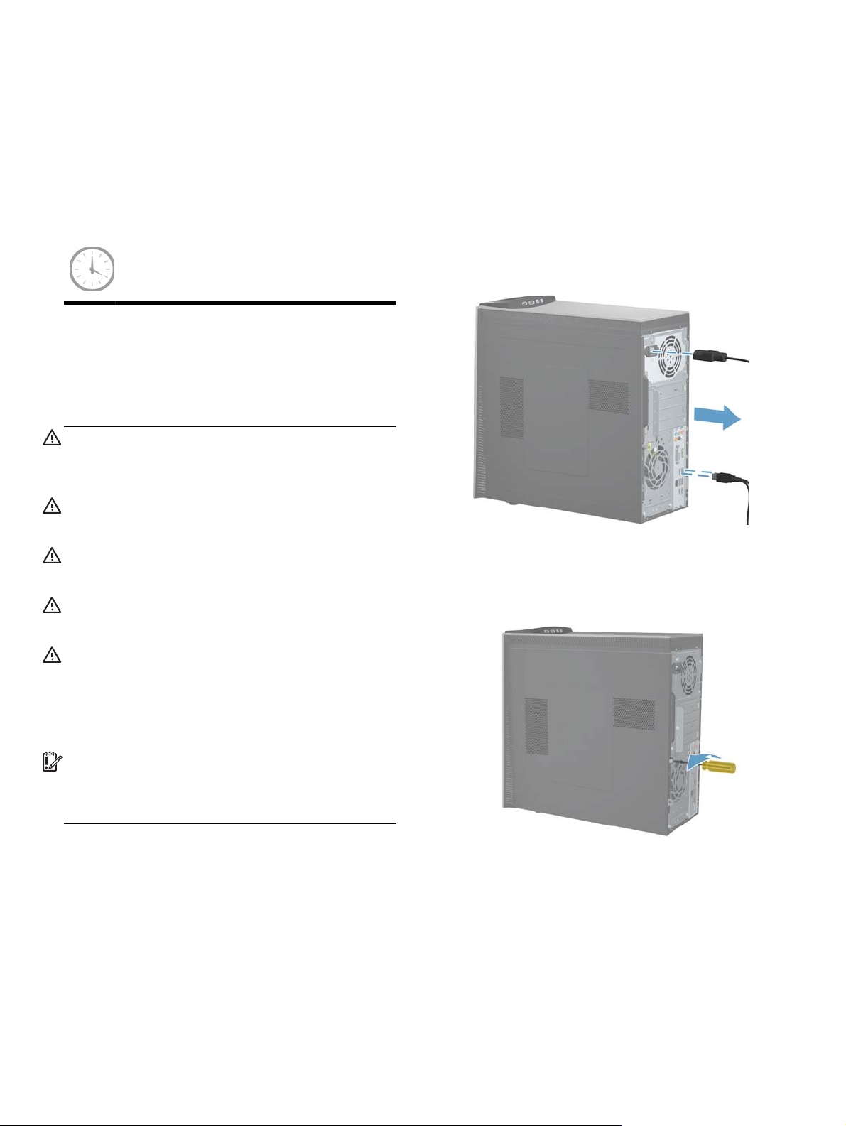
3. Unplug the computer by disconnecting the
power cord and all attached cables from the
back of the computer.
WARNING! Keep your hands away from the
moving fan.
WARNING! Keep fingers and tools clear of the
fan when the power is applied.
CAUTION: Static electricity can damage the
electronic components inside the computer. Discharge
static electricity by touching the metal cage of the
computer before touching any internal parts or
electronic components.
IMPORTANT: A hard disk drive is extremely
sensitive to shock impact. Do not bang or drop it. Do
not touch the circuit board. Static electricity can
damage the drive.
Tools Needed
Flathead/T15 Torx screwdriver
●
Small screws are easily lost. Remove screws over a
surface that enables you to retrieve them if they fall.
4. Using a flathead or Torx screwdriver, loosen the
screw on the back panel that secures the panel
to the computer.
2 Upgrading and Servicing Guide Features may vary by model.
Page 5
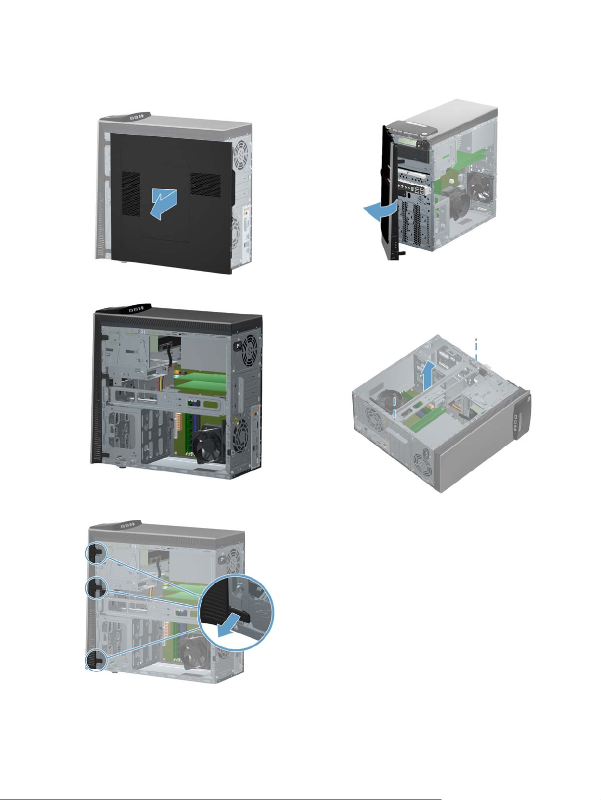
5. Slide the side panel toward the back of the
computer, and then pull the side panel away
from the computer.
7. Open the front bezel, and then remove it from
the computer.
The inside of the computer is exposed.
6. Lift the three tabs on the front bezel to release it.
8. Lay the computer on a flat surface.
9. Remove the two screws holding the retaining bar
in place.
Features may vary by model.
Removing and Replacing a Hard Disk Drive
3
Page 6
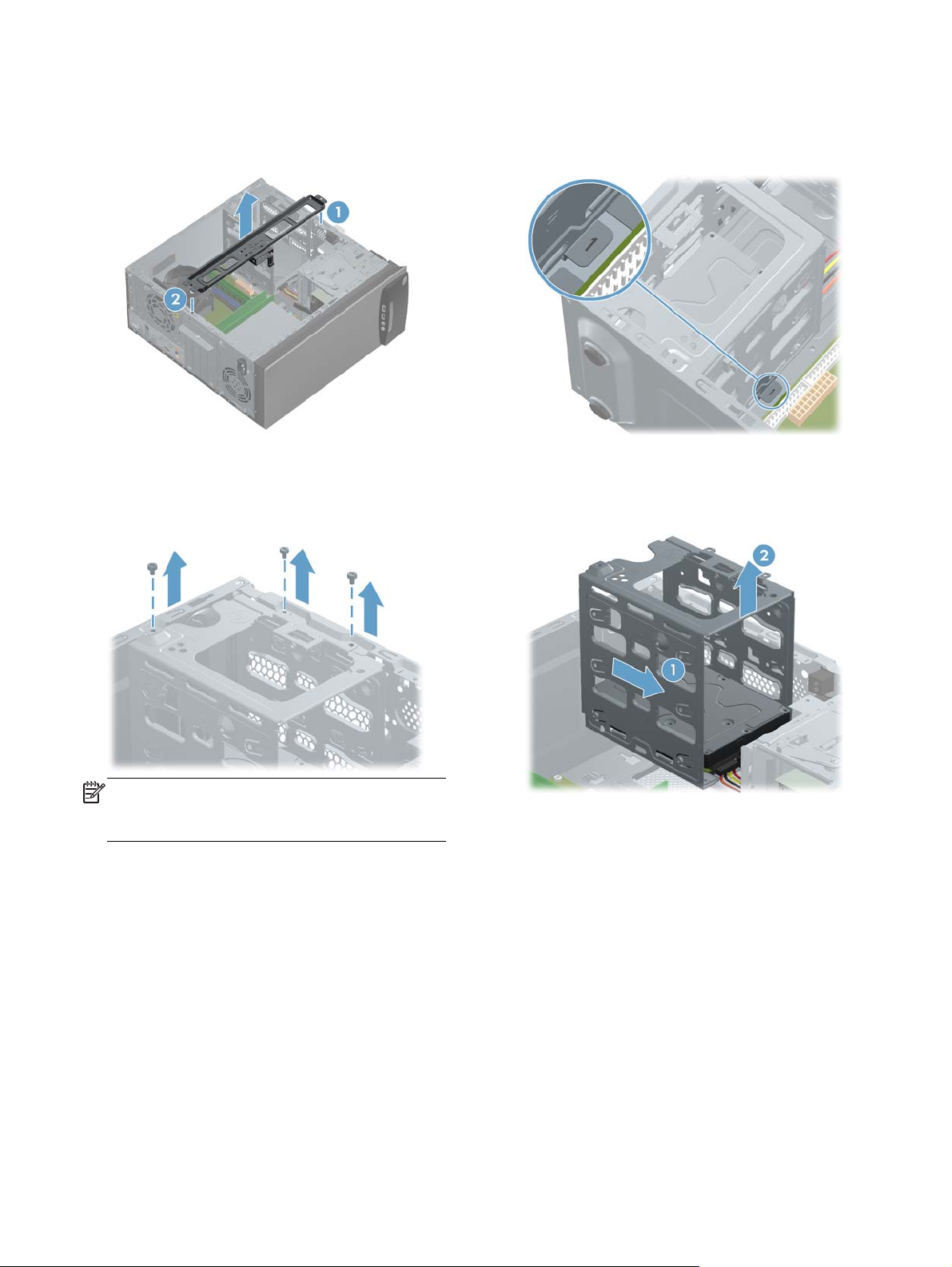
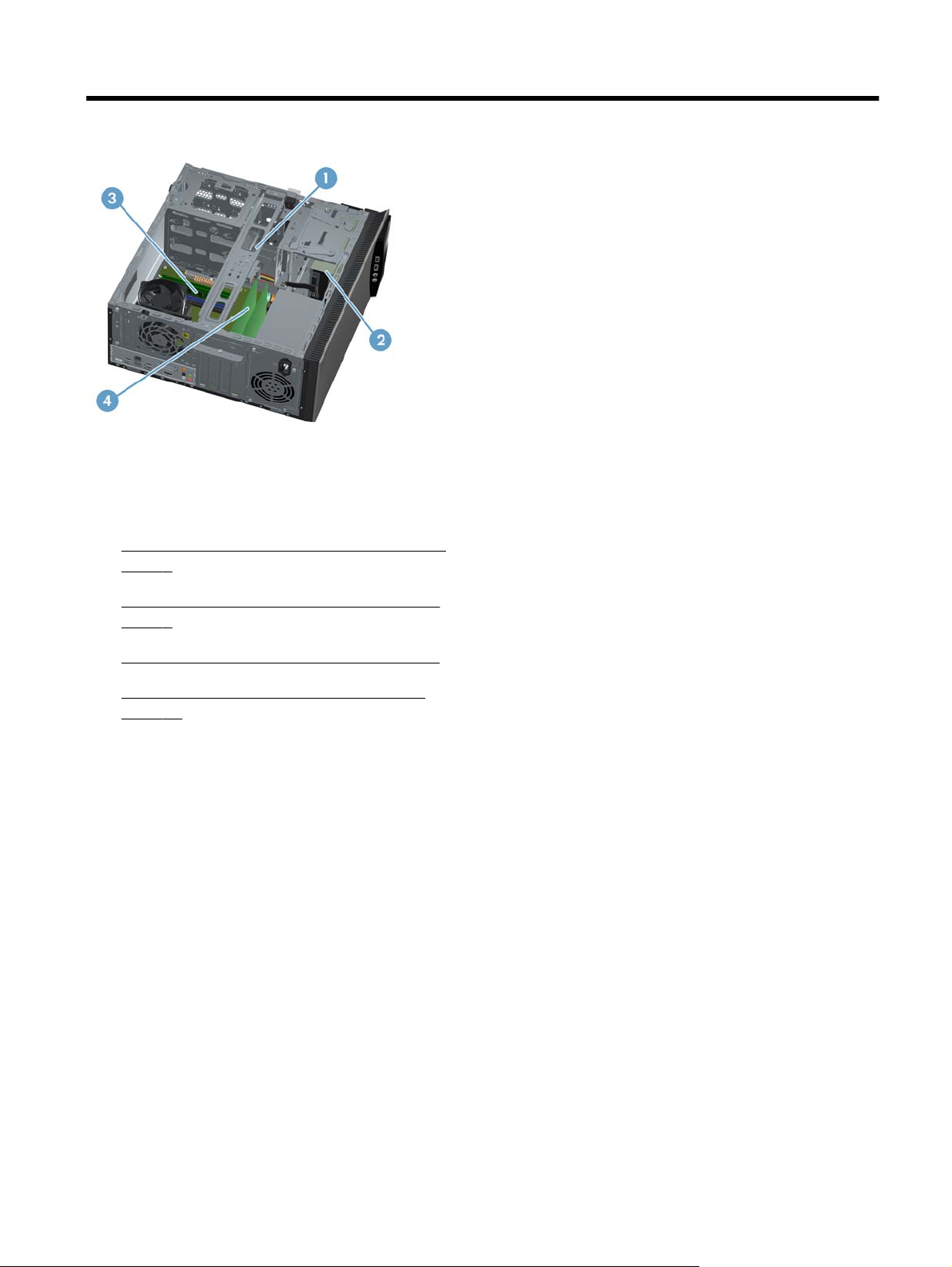
10. Lift the retaining bar at the front of the computer
(1), and then remove it from the back of the
computer (2).
12. Using a screwdriver, push the lever marked “1”
on the base of the right side of the hard drive
cage by the motherboard.
11. Remove the three screws that attach the hard
disk drive cage to the computer.
NOTE: Some models may have only two
screws attaching the hard disk drive cage to the
computer.
13. Grasp the hard drive cage and slide the cage
toward the CD/DVD drive (1), and then lift the
cage out of the computer (2).
4 Upgrading and Servicing Guide Features may vary by model.
Page 7
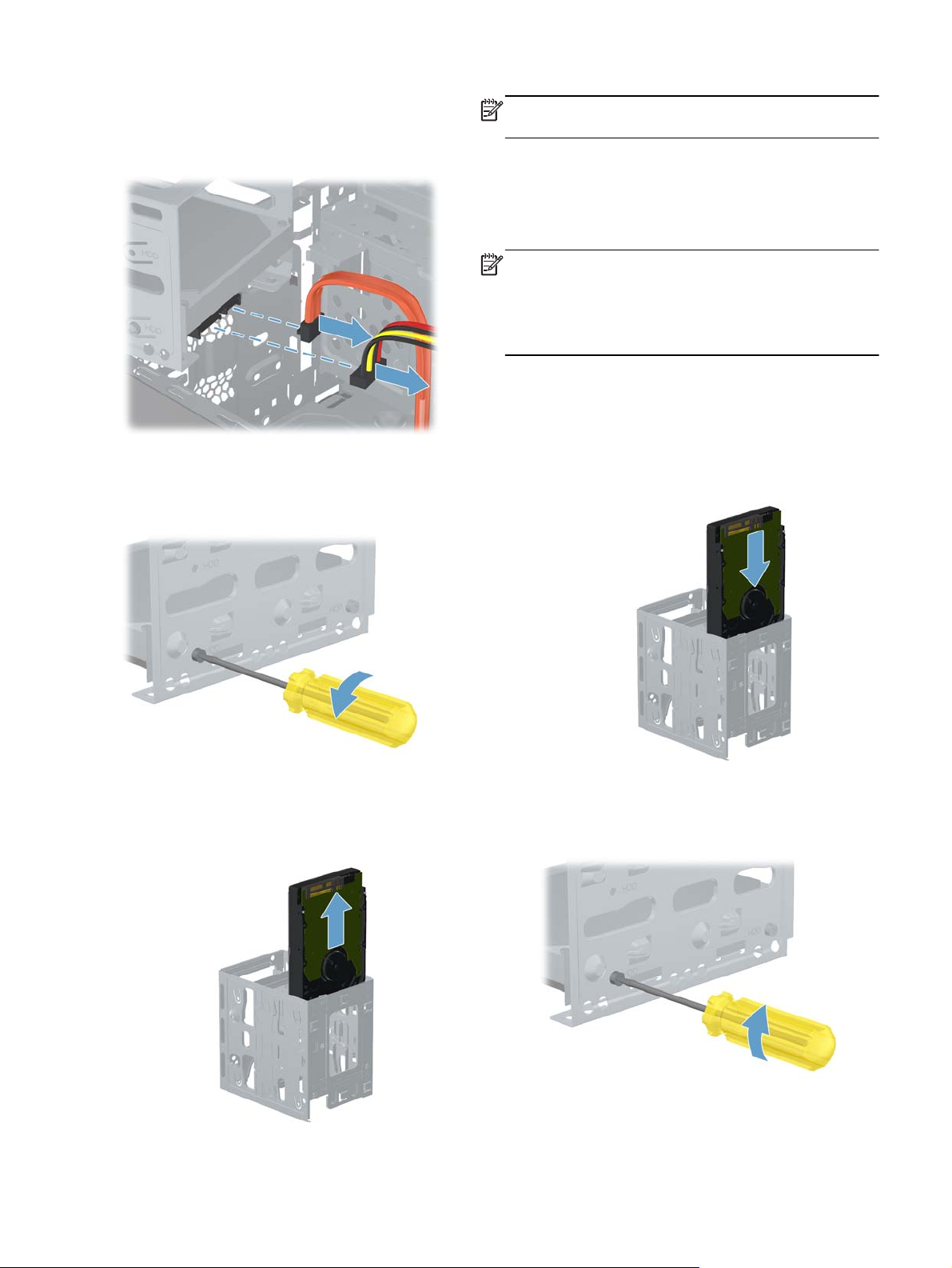
14. Disconnect the two cables from the end of the
hard disk drive. The cables may have a latch
that is pressed to release the cable.
15. To remove the hard disk drive from the cage,
remove two screws on each side of the cage
that secure the hard disk drive to the cage.
NOTE: Keep the four screws available as they will
be used in the new hard drive.
Installing a new hard disk drive
NOTE: The replacement part may look different
than the original part because of manufacturer or
model differences; however, the replacement part
meets or exceeds the specifications of the original
part.
1. Insert the new hard drive into the hard drive
cage, making sure that the connectors on the
hard drive are on the same end of the cage as
the handle. The hard drive rests on the metal
tabs located inside the cage.
16. Slide the hard disk drive out of the cage.
Features may vary by model.
2. Install the four screws that secure the hard drive
to the cage.
Removing and Replacing a Hard Disk Drive
5
Page 8
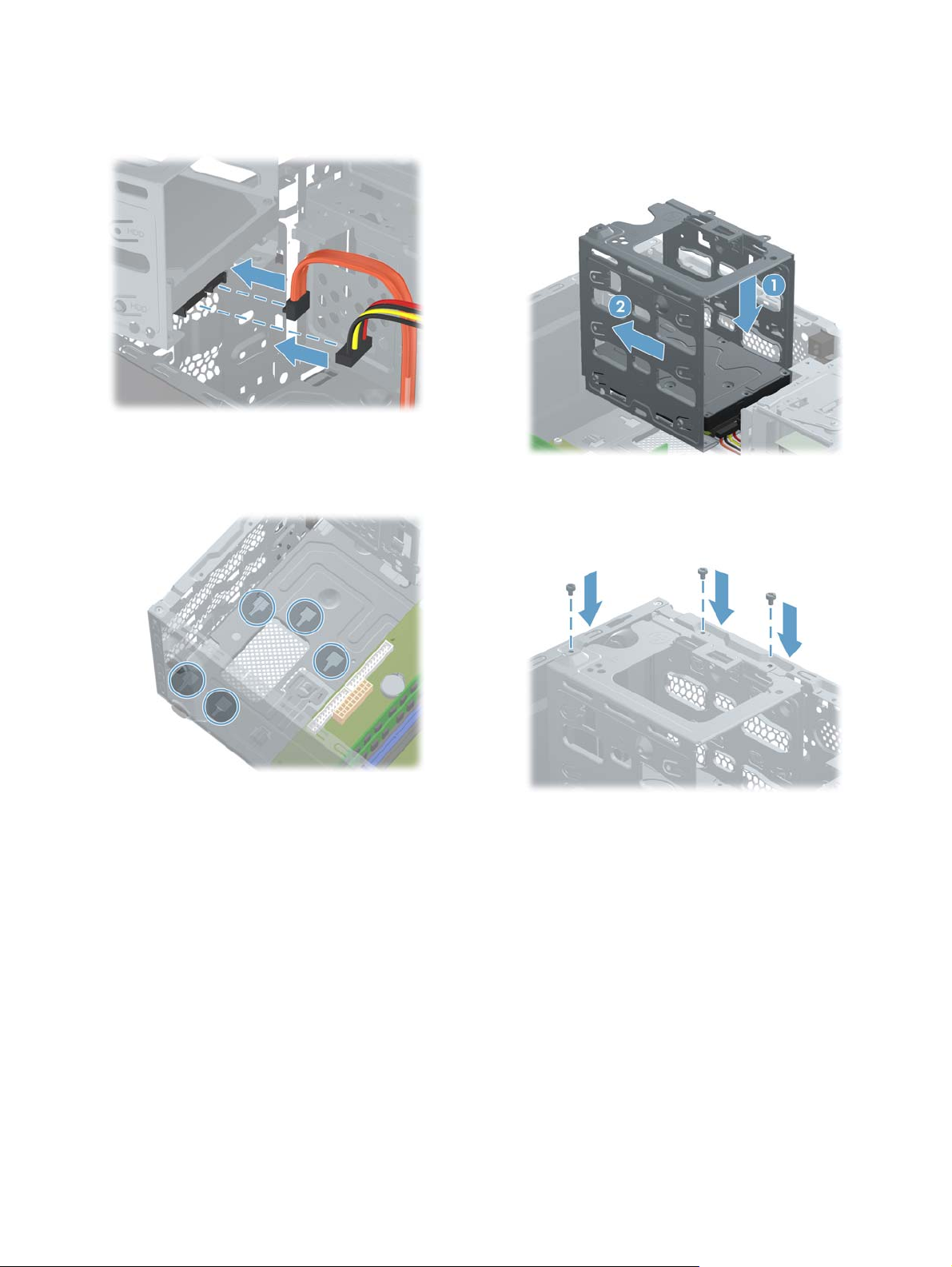
3. Reattach the cables to the bottom end of the
hard disk drive.
4. Set the hard drive cage down into the bay,
aligning the tabs on the bottom of the cage with
the slots on the chassis.
5. Once the cage is set on the slots (1), press down
and slide the cage toward the bottom of the
computer until it stops (2), ensuring that the three
screw holes are aligned.
6. Using a flathead or Torx screwdriver, secure the
hard disk drive cage in place.
6 Upgrading and Servicing Guide Features may vary by model.
Page 9

7. Insert the retaining bar in the back of the
computer (1), and then align the screw holes at
the front of the computer (2).
10. Insert the three tabs on the bezel door into the
slots on the computer, and then close the bezel
door until it locks in place.
8. Insert the two screws, securing the retaining bar
in place.
9. Place the computer in an upright position.
11. Install the side panel on the side of the
computer, and then slide it toward the front of
the computer.
NOTE: Make sure the panel is flush with the
computer. Failure to do so might cause the panel
to bend slightly outward and not close securely.
Features may vary by model.
Removing and Replacing a Hard Disk Drive
7
Page 10

12. Tighten the screw, securing the side panel to the
back of the computer.
13. Plug the power cord and any additional cables
into the back of the computer.
14. Press the power button to turn on the computer.
NOTE: If your hard disk drive was shipped
without an operating system installed, you will
need to reinstall it using the system recovery
discs.
To install the operating system, refer to the
instructions included with your system recovery
discs, or available from the HP support site
(www.hp.com/support).
After the operating system has been installed,
you will need to reinstall any applications and
restore any data you backed up.
8 Upgrading and Servicing Guide Features may vary by model.
Page 11

Removing and
Removing the CD/DVD drive
Replacing a CD/DVD
Drive
Computer features may vary by model.
10 – 15 minutes
Before you begin
Observe the following requirements before removing
and replacing the CD/DVD drive.
WARNING! Never open the cover with the power
applied. You might damage your computer or be
injured by the spinning the fan blades.
WARNING! Avoid touching sharp edge inside the
computer.
1. Remove any media or storage devices such as
CDs, DVDs, and USB.
2. Close all programs, and then shut down your
operating system.
3. Unplug the computer by disconnecting the
power cord and all attached cables from the
back of the computer.
WARNING! Keep your hands away from the
moving fan.
WARNING! Keep fingers and tools clear of the
fan when the power is applied.
CAUTION: Static electricity can damage the
electronic components inside the computer. Discharge
static electricity by touching the metal cage of the
computer before touching any internal parts or
electronic components.
IMPORTANT: A CD/DVD drive is extremely
sensitive to shock impact. Do not bang or drop it.
Tools Needed
Flathead/T15 Torx screwdriver
●
Small screws are easily lost. Remove screws over a
surface that enables you to retrieve them if they fall.
4. Using a flathead or Torx screwdriver, loosen the
screw at the back of the computer that secures
the side panel to the computer.
Features may vary by model.
Removing and Replacing a CD/DVD Drive
9
Page 12

5. Slide the side panel toward the back of the
computer, and then pull the side panel away
from the computer.
7. Open the front bezel, and then remove it from
the computer.
The inside of the computer is exposed.
6. Lift the three tabs on the front bezel to release it.
8. To unlock the CD/DVD drive, pull “Lever A”
slightly out and release the lever in the center
position. Numbers “1” and “2” will both be
exposed.
If you have more than one CD/DVD drive to
remove, repeat this step. However, instead of
moving “Lever A”, move “Lever B.”
10 Upgrading and Servicing Guide Features may vary by model.
Page 13

9. Remove the cables from the back of the CD/
DVD drive. The cables may have a latch that is
pressed to release the cable.
10. Push the CD/DVD drive from behind.
Installing a new CD/DVD drive
NOTE: The replacement part may look different
than the original part because of manufacturer or
model differences; however, the replacement part
meets or exceeds the specifications of the original
part.
1. Locate where the CD/DVD drive is to be
inserted.
11. Pull the CD/DVD drive out the front of the
computer.
2. Insert the new CD/DVD drive into the slot.
Features may vary by model.
Removing and Replacing a CD/DVD Drive
11
Page 14

3. Slide the CD/DVD drive all the way into the slot.
4. To lock the CD/DVD drive in place, move “Lever
A” to the number “2” position. Slide the CD/
DVD drive out slightly until “Lever A” latches into
position to secure the drive.
5. Connect the cables to the back of the CD/DVD
drive.
6. Reattach the front bezel by inserting the three
tabs into the slots on the computer, and then
close the bezel door until it locks in place.
If you have more than one CD/DVD drive to
install, repeat this step. However, instead of
moving “Lever A”, move “Lever B.”
12 Upgrading and Servicing Guide Features may vary by model.
Page 15

7. Install the side panel on the side of the
computer, and then slide it toward the front of
the computer.
9. Plug the power cord and any additional cables
into the back of the computer.
NOTE: Make sure the panel is flush with the
computer. Failure to do so might cause the panel
to bend slightly outward and not close securely.
8. Tighten the screw, securing the side panel to the
back of the computer.
10. Press the power button to turn on the computer.
Features may vary by model.
Removing and Replacing a CD/DVD Drive
13
Page 16

Upgrading or Replacing Memory
Computer features may vary by model.
10 – 15 minutes
Before you begin
most other DIMMs, so that they take less space in the
case. SO-DIMM modules must meet the following
requirements:
204-pin DDR3-DIMM
●
PC3-10600 (1333 MHz) DDR3-SDRAM
●
Unbuffered, non-ECC (64-bit) DIMMs
●
1.5 V memory only
●
16.0 GB maximum installable memory using
●
4GB Modules. Actual available memory that
can be used in Windows will be less.
Observe the following requirements before removing
and replacing memory.
WARNING! Never open the cover with the power
applied. You might damage your computer or be
injured by the spinning the fan blades.
WARNING! Avoid touching sharp edge inside the
computer.
WARNING! Keep your hands away from the
moving fan.
WARNING! Keep fingers and tools clear of the
fan when the power is applied.
CAUTION: Static electricity can damage the
electronic components inside the computer. Discharge
static electricity by touching the metal cage of the
computer before touching any internal parts or
electronic components.
IMPORTANT: A memory card is extremely
sensitive to shock impact. Do not bang or drop it.
Static electricity can damage the card.
Because the memory uses dual channels, you should
use the same DIMM type for both sockets.
NOTE: The actual memory transfer speed can vary
based on the CPU used in your computer.
Removing the memory
1. Remove any media or storage devices such as
CDs, DVDs, and USB.
2. Close all programs, and then shut down your
operating system.
3. Unplug the computer by disconnecting the
power cord and all attached cables from the
back of the computer.
Tools Needed
Flathead/T15 Torx screwdriver
●
Small screws are easily lost. Remove screws over a
surface that enables you to retrieve them if they fall.
Memory Compatibility
Verify that the memory installed is compatible with
this computer. SO-DIMMs are small outline dual inline
memory modules. They are smaller and thinner than
14 Upgrading and Servicing Guide Features may vary by model.
Page 17

4. Using a flathead or Torx screwdriver, loosen the
screw at the back of the computer that secures
the side panel to the computer.
6. Lay the computer on a flat surface.
7. Locate the memory inside the computer.
5. Slide the side panel toward the back of the
computer, and then pull the side panel away
from the computer.
The inside of the computer is exposed.
8. To release the memory card, press outwards on
the retaining clips on the left and right sides of
the top memory card (1). Holding the memory
card by the edges, gently remove it from the
compartment (2).
9. To remove additional memory cards, repeat step
8.
Features may vary by model.
Upgrading or Replacing Memory
15
Page 18

Installing a new memory card
NOTE: The replacement part may look different
than the original part because of manufacturer or
model differences; however, the replacement part
meets or exceeds the specifications of the original
part.
1. Orient the new memory card so that the notch in
the memory card aligns with the tab in the
socket.
5. Install the side panel on the side of the
computer, and then slide it toward the front of
the computer.
NOTE: Make sure the panel is flush with the
computer. Failure to do so might cause the panel
to bend slightly outward and not close securely.
6. Tighten the screw, securing the side panel to the
back of the computer.
2. Holding the memory card by the edges, press
the card into the socket. Make sure the memory
card is pressed completely into the socket, and
then gently push down on the card until it snaps
in place.
3. If you are replacing more than one memory
card, repeat step 2 for each memory card.
4. Place the computer in an upright position.
16 Upgrading and Servicing Guide Features may vary by model.
Page 19

7. Plug the power cord and any additional cables
into the back of the computer.
8. Press the power button to turn on the computer.
Troubleshooting
If the computer displays a memory error after you
have turned it back on:
1. Turn the computer off and unplug the power
cord.
2. Open up the memory compartment and make
sure the memory card is firmly seated.
3. To install the memory card correctly, make sure
it is inserted all the way into the compartment
and then push down on it to snap it into place.
Features may vary by model.
Upgrading or Replacing Memory
17
Page 20

Upgrading or Replacing
Removing the add-in card
an Add-in Card
Computer features may vary by model.
10 – 15 minutes
Before you begin
Observe the following requirements before removing
and replacing the add-in card.
WARNING! Never open the cover with the power
applied. You might damage your computer or be
injured by the spinning the fan blades.
WARNING! Avoid touching sharp edge inside the
computer.
WARNING! Keep your hands away from the
moving fan.
WARNING! Keep fingers and tools clear of the
fan when the power is applied.
1. Remove any media or storage devices such as
CDs, DVDs, and USB.
2. Close all programs, and then shut down your
operating system.
3. Unplug the computer by disconnecting the
power cord and all attached cables from the
back of the computer.
4. Using a flathead or Torx screwdriver, loosen the
screw at the back of the computer that secures
the side panel to the computer.
CAUTION: Static electricity can damage the
electronic components inside the computer. Discharge
static electricity by touching the metal cage of the
computer before touching any internal parts or
electronic components.
IMPORTANT: A add-in card is extremely sensitive
to shock impact. Do not bang or drop it. Static
electricity can damage the card.
Tools Needed
Flathead/T15 Torx screwdriver
●
Small screws are easily lost. Remove screws over a
surface that enables you to retrieve them if they fall.
18 Upgrading and Servicing Guide Features may vary by model.
Page 21

5. Slide the side panel toward the back of the
computer, and then pull the side panel away
from the computer.
8. Lift the retaining bar at the front of the computer
(1), and then remove it from the back of the
computer (2).
The inside of the computer is exposed.
6. Lay the computer on a flat surface.
7. Remove the two screws holding the retaining bar
in place.
9. On the back of the computer, locate the screw
holding the bracket in place.
10. Remove the screw that secures the bracket to the
computer.
Features may vary by model.
Upgrading or Replacing an Add-in Card
19
Page 22

11. Remove the bracket from the back of the
computer.
13. If the add-in card is in the large slot, press the
latch to release the card.
12. To make it easier to access the add-in cards,
disconnect the auxiliary power cable from the
motherboard.
Carefully lift the add-in card out by the edges.
14. If the add-in card is in one of the smaller slots,
gently lift the card out to remove it. If there are
connectors attached to the card, remove them.
15. If there are additional add-in cards to be
removed, repeat step 14 for each card.
20 Upgrading and Servicing Guide Features may vary by model.
Page 23

Installing a new add-in card
NOTE: The replacement part may look different
than the original part because of manufacturer or
model differences; however, the replacement part
meets or exceeds the specifications of the original
part.
1. Locate where the card will be seated inside the
computer.
2. Insert the add-in card into the slot on the
motherboard, making sure it is firmly seated in
place.
Features may vary by model.
3. If the auxiliary power cable was removed,
reconnect it to the motherboard.
Upgrading or Replacing an Add-in Card
21
Page 24

4. To secure the add-in card in place, replace the
bracket at the back of the computer.
7. Insert the two screws, securing the retaining bar
in place.
5. Reattach the screw holding the bracket in place.
6. Insert the retaining bar in the back of the
computer (1), and then align the screw holes at
the front of the computer (2).
8. Place the computer in an upright position.
9. Install the side panel on the side of the
computer, and then slide it toward the front of
the computer.
NOTE: Make sure the panel is flush with the
computer. Failure to do so might cause the panel
to bend slightly outward and not close securely.
22 Upgrading and Servicing Guide Features may vary by model.
Page 25

10. Tighten the screw, securing the side panel to the
back of the computer.
11. Plug the power cord and any additional cables
into the back of the computer.
12. Press the power button to turn on the computer.
Features may vary by model.
Upgrading or Replacing an Add-in Card
23
 Loading...