

Page 1
Product Category: Personal Computers
Marketing Name / Model
[List multiple models if applicable.]
HP Envy 23 TouchSmart All-in-One PC
1.0 Items Requiring Selective Treatment
Item Description
Notes
Quantity
of items
included
in product
Printed Circuit Boards (PCB) or Printed Circuit
Assemblies (PCA)
With a surface greater than 10 sq cm
MB, scalar, sidekey, webcam, b-cas,
converterboard, Graphic card
8
Batteries
All types including standard alkaline and lithium coin
or button style batteries
7
Mercury-containing components
For example, mercury in lamps, display backlights,
scanner lamps, switches, batteries
0
Liquid Crystal Displays (LCD) with a surface greater
than 100 sq cm
Includes background illuminated displays with gas
discharge lamps LED Panel
1
Cathode Ray Tubes (CRT)
0
Capacitors / condensers (Containing PCB/PCT)
0
Electrolytic Capacitors / Condensers measuring
greater than 2.5 cm in diameter or height
0
External electrical cables and cords
1
Gas Discharge Lamps
0
Plastics containing Brominated Flame Retardants
weighing > 25 grams (not including PCBs or PCAs
already listed as a separate item above)
0
Components and parts containing toner and ink,
including liquids, semi-liquids (gel/paste) and toner
Include the cartridges, print heads, tubes, vent
chambers, and service stations.
0
Components and waste containing asbestos
0
Components, parts and materials containing
0
Product End-of-Life Disassembly Instructions
Purpose: The document is intended for use by end-of-life recyclers or treatment facilities. It provides the basic instructions
for the disassembly of HP products to remove components and materials requiring selective treatment, as defined by EU
directive 2002/96/EC, Waste Electrical and Electronic Equipment (WEEE).
1.1 Items listed below are classified as requiring selective treatment.
1.2 Enter the quantity of items contained within the product which require selective treatment in the right column, as
applicable.
EL-MF877-00 Page 1
Template Revision B
PSG instructions for this template are available at EL-MF877-01
Page 2

refractory ceramic fibers
Components, parts and materials containing
radioactive substances
0
2.0 Tools Required
List the type and size of the tools that would typically be used to disassemble the product to a point where components
Tool Description
Tool Size (if
applicable)
Description #1 Electric screw driver
2# X10
Description #2 Electric screw driver
1# X10
3.0 Product Disassembly Process
and materials requiring selective treatment can be removed.
3.1 List the basic steps that should typically be followed to remove components and materials requiring selective treatment:
Please refer to the 3.1.2 disassemble hinge and real cover
Please refer to the 3.1.3 disassemble the stand
Please refer to the 3.1.4 Remove MB shielding
Please refer to the 3.1.5 disassemble HDD & ODD
Please refer to the 3.1.6 disassemble B-case
Please refer to the 3.1.7 disassemble visa mount.
Please refer to the 3.1.8 disassemble Speaker
Please refer the 3.1.9/10/11 disassemble CPU/thermal module/system fan
Please refer to 3.1.12/13 disassemble scalar & converter board.
Please refer to 3.1.14 disassemble webcam
Please refer to 3.1.15 disassemble microphone
Please refer to 3.1.16 disassemble wireless card
Please refer to 3.1.17 disassemble TV card.
Please refer to 3.1.18 disassemble MB and battery remove
Please refer to 3.1.19 disassemble CPU & DDR.
Please refer to 3.1.20 disassemble Base pan and touch module.
Please refer to 3.1.21 Remove Mouse/Keyboard Battery/MB
Please refer to 3.1.22 Remove power supply
3.2 Optional Graphic. If the disassembly process is complex, insert a graphic illustration below to identify the items
contained in the product that require selective treatment (with descriptions and arrows identifying locations).
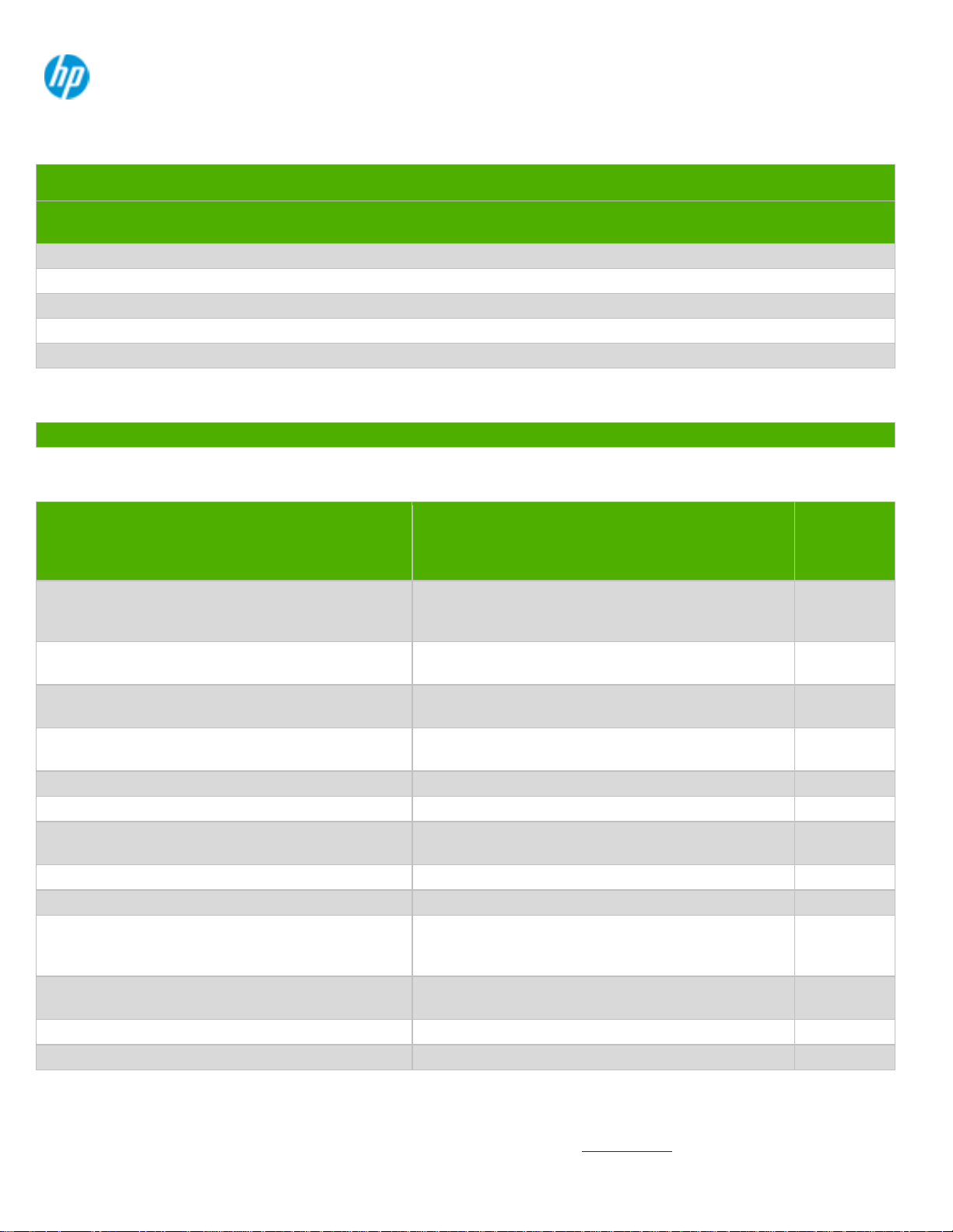
Figure 1 : Mechanical parts disassembly
1) Place the system
EL-MF877-00 Page 2
Template Revision B
PSG instructions for this template are available at EL-MF877-01
Page 3
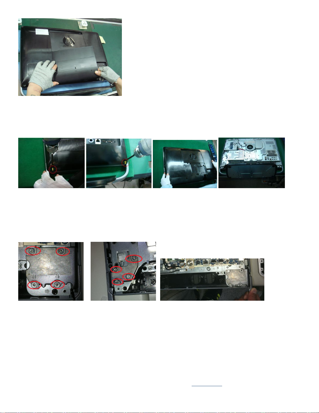
2) Disassemble hinge cover and real cover..
Remove the screws with circle in red.
3) Disassemble stand
Remove four screws on both left and right so you can remove stand with two hands.
4) Disassemble MB shielding
Remove the screws with circles in red.
EL-MF877-00 Page 3
Template Revision B
PSG instructions for this template are available at EL-MF877-01
Page 4
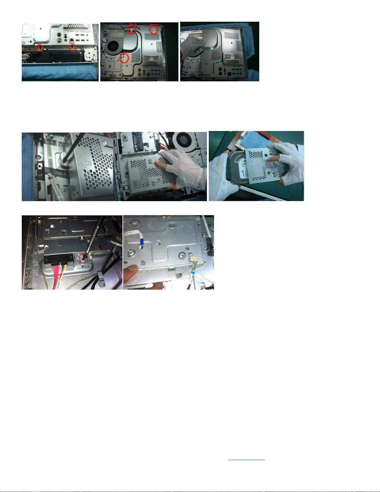
5) Disassemble HDD & ODD
Remove one screw from HDD and pull backward to disengage the HDD from base pan.
Remove one screw and push ODD forward to slide from ODD cage.
6) Disassemble B-case ( with Japan SKU that has B-case module)
Remove the following screws that have circulated in yellow
EL-MF877-00 Page 4
Template Revision B
PSG instructions for this template are available at EL-MF877-01
Page 5

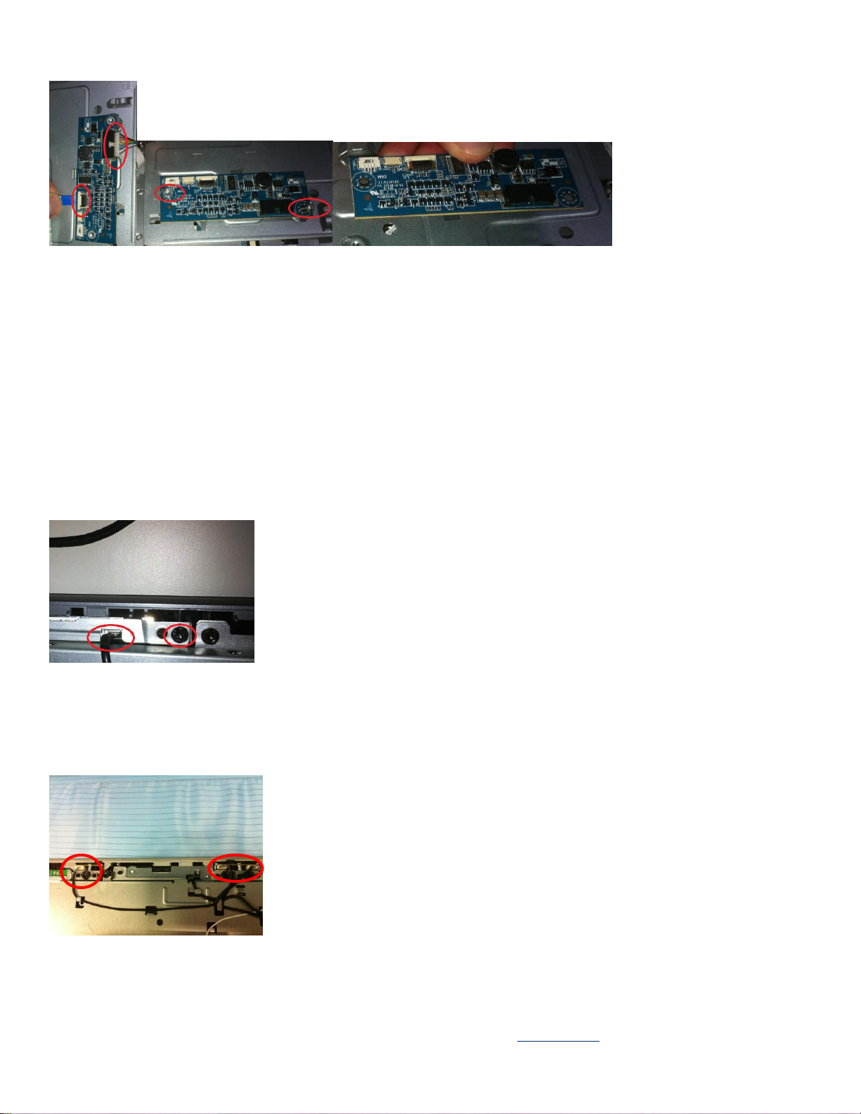
7) Disassemble for VESA mount ( only for the scalar)
Remove the following screws that have circulated in red.
8) Disassemble speaker
Remove two screws from left and right. Also remove the speaker cable in order to take out two speakers from system.
EL-MF877-00 Page 5
Template Revision B
PSG instructions for this template are available at EL-MF877-01
Page 6

9) Disassemble CPU thermal module
Remove five screws and remove away the thermal module.
10) Disassemble MXM thermal module and remove the graphic card (with Graphic card module)
Remove five screws to remove the thermal module and disengage the graphic card from slot.
11) Disassemble FAN
Remove three screws and remove one calbe to disassemble the fan.
EL-MF877-00 Page 6
Template Revision B
PSG instructions for this template are available at EL-MF877-01
Page 7

12) Disassemble Scalar Board ( that has scalar SKU) and side key.
Remove the following screws and cables that have circulated in yellow
13) Dissemble Converter board
Remove two cable and screws to disassemble the CVB.
EL-MF877-00 Page 7
Template Revision B
PSG instructions for this template are available at EL-MF877-01
Page 8
14) Disassemble webcam
Remove the cable and screw in order to disengage the webcam module and mechanical parts.
15) Disassemble MIC.
Remove the cable and screw in order to disengage the MIC module and mechanical parts.
EL-MF877-00 Page 8
Template Revision B
PSG instructions for this template are available at EL-MF877-01
Page 9

16) Disassemble Wireless card
Remove one screw and two cables in order to remove wireless card.
17) Remove TV card
Remove one screw and two connectors to remove the TV card.
18) Remove MB & MB battery
Remove 9 screws to disassemble the INTEL/AMD MB.
Pull backward the clip to release the battery
EL-MF877-00 Page 9
Template Revision B
PSG instructions for this template are available at EL-MF877-01
Page 10

19) Disassemble CPU and DDR
Remove the CPU by releasing the hook for Intel (above) & AMD (below).
(
Pull both clicks outward that holding the memory to remove the DDR
20) Separate BASE pan and touch module
Un-plug cable from touch control board(Left/Bottom)side.
Remove screws *4 to diassemble LCM and front bezel
EL-MF877-00 Page 10
Template Revision B
PSG instructions for this template are available at EL-MF877-01
Page 11
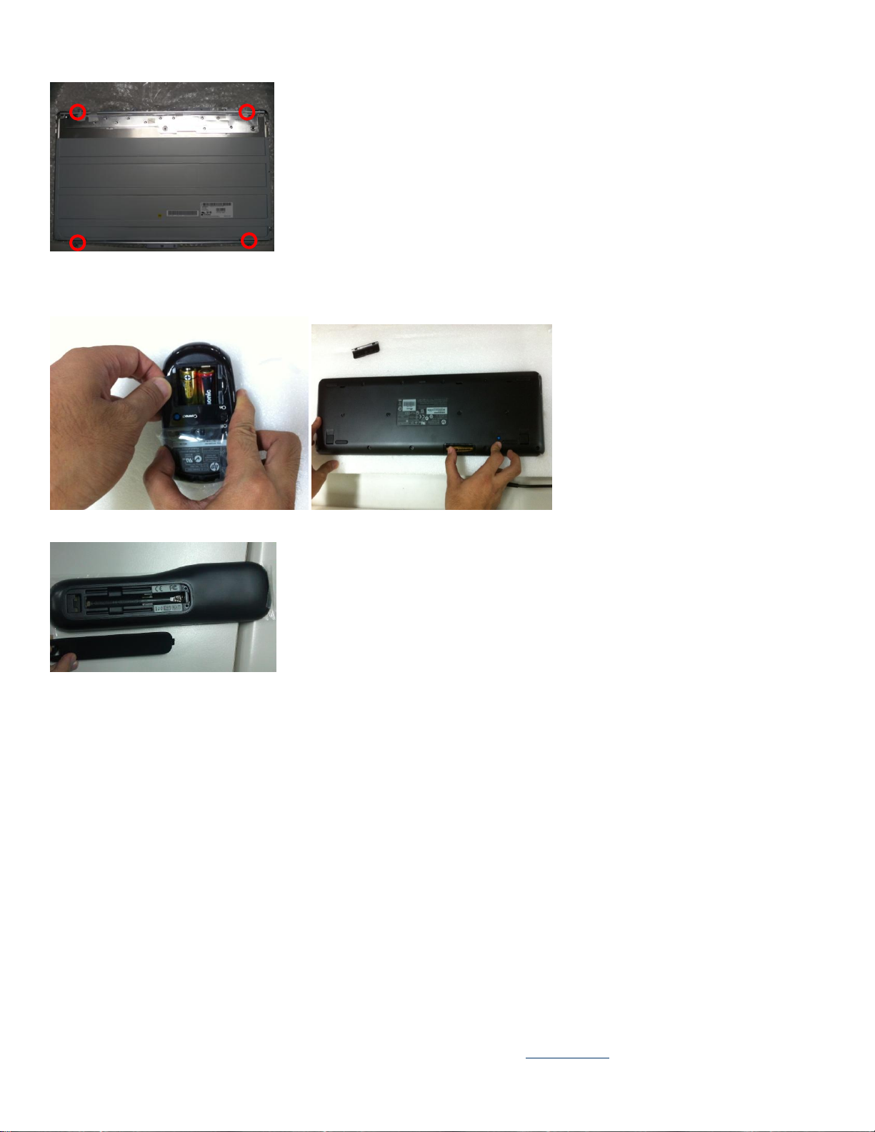
Remove Screws M3 x5 from LCM to disassemble LCD bracket.
21) Remove Mouse/Keyboard Battery/MB
22) Remove power supply
EL-MF877-00 Page 11
Template Revision B
PSG instructions for this template are available at EL-MF877-01
Page 12

EL-MF877-00 Page 12
Template Revision B
PSG instructions for this template are available at EL-MF877-01
 Loading...