

Page 1
Product Category: Monitors and Displays
Marketing Name / Model
[List multiple models if applicable.]
HP EliteDisplay E220t Touch Monitor
1.0 Items Requiring Selective Treatment
Item Description
Notes
Quantity
of items
included
in product
Printed Circuit Boards (PCB) or Printed Circuit
Assemblies (PCA)
With a surface greater than 10 sq cm
Power Board, USB Board, IF Board, Keypad
4
Batteries
All types including standard alkaline and lithium coin
or button style batteries
Mercury-containing components
For example, mercury in lamps, display backlights,
scanner lamps, switches, batteries
Liquid Crystal Displays (LCD) with a surface greater
than 100 sq cm
Includes background illuminated displays with gas
discharge lamps
Cathode Ray Tubes (CRT)
Capacitors / condensers (Containing PCB/PCT)
Electrolytic Capacitors / Condensers measuring
greater than 2.5 cm in diameter or height
External electrical cables and cords
Gas Discharge Lamps
Plastics containing Brominated Flame Retardants
weighing > 25 grams (not including PCBs or PCAs
already listed as a separate item above)
Components and parts containing toner and ink,
including liquids, semi-liquids (gel/paste) and toner
Include the cartridges, print heads, tubes, vent
chambers, and service stations.
Components and waste containing asbestos
Components, parts and materials containing
refractory ceramic fibers
Product End-of-Life Disassembly Instructions
Purpose: The document is intended for use by end-of-life recyclers or treatment facilities. It provides the basic instructions
for the disassembly of HP products to remove components and materials requiring selective treatment, as defined by EU
directive 2002/96/EC, Waste Electrical and Electronic Equipment (WEEE).
1.1 Items listed below are classified as requiring selective treatment.
1.2 Enter the quantity of items contained within the product which require selective treatment in the right column, as
applicable.
EL-MF877-00 Page 1
Template Revision B
PSG instructions for this template are available at EL-MF877-01
Page 2
Components, parts and materials containing
radioactive substances
2.0 Tools Required
List the type and size of the tools that would typically be used to disassemble the product to a point where components
Tool Description
Tool Size (if
applicable)
Cross Screwdriver
Ph2/Ph0
Six corner sleeve Screwdriver
Disassembly Tool / Slotted Screwdriver
Description #4
Description #5
3.0 Product Disassembly Process
Below action which may easily damage product .please notice it
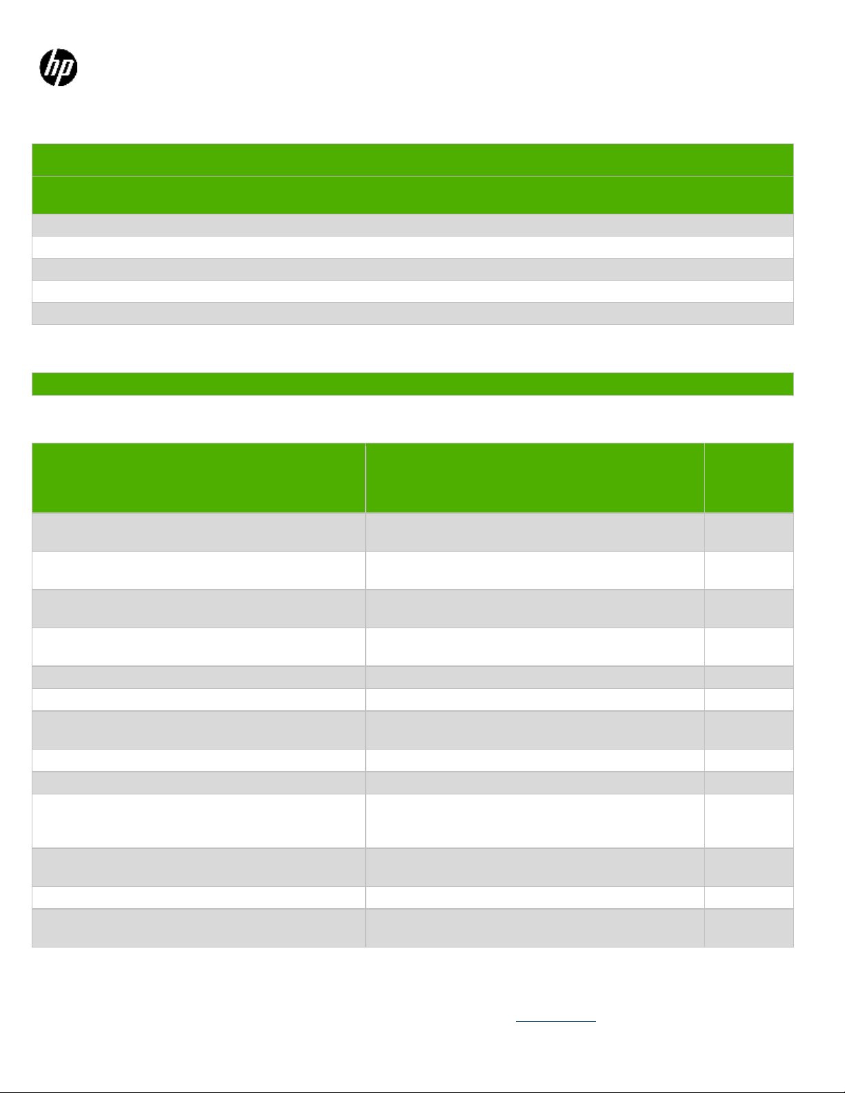
Lay the
monitor on
the desk,
pivot the
stand and
unlock the
4 screws.
Ph2 Cross
Screwdriver
Separate the
bottom of
Middle
Cover from
Bucket, and
then reverse
the monitor
head.
N/A
and materials requiring selective treatment can be removed.
3.1 List the basic steps that should typically be followed to remove components and materials requiring selective treatment:
1. Lay the monitor on the desk, pivot the stand and unlock the 4 screws.
2. Separate the bottom of Middle Cover from Bucket, then reverse the monitor head.
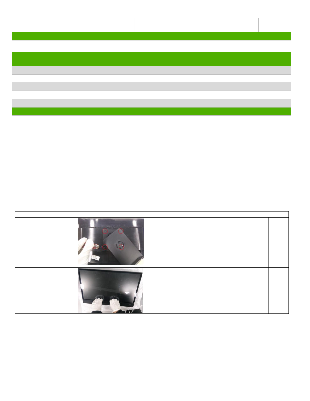
3. Separate Bucket from middle cover with a slotted screwdriver, by an order: bottom, sides and top.
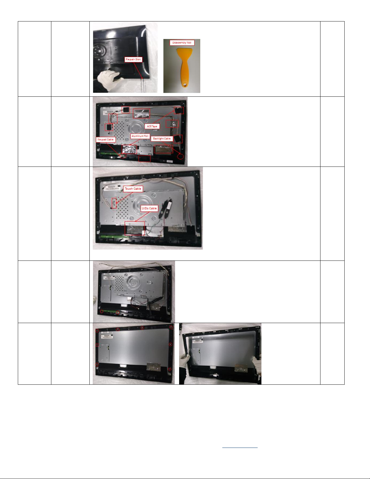
4. Take out all of ACE Tape and Aluminum Foil, then separate the Backlight Cable and Keypad Cable.
5. Move away the Speakers and Chassis, take out the ACE Tape and Aluminum Foil, then separate the Touch Cable and
LVDs Cable.
6. Unlock the 2 screws and take out the Keypad Board.
7. Unlock the 8 screws and separate Panel from Middle Cover.
8. Unlock the screws and 2 bolts.
9. Take away the ACE Tape and Mylar, then unlock the10 screws.
10. Take out the Power Board, USB Board and IF Board from Chassis, then separate all cables from connectors.
3.2 Optional Graphic. If the disassembly process is complex, insert a graphic illustration below to identify the items
contained in the product that require selective treatment (with descriptions and arrows identifying locations).
EL-MF877-00 Page 2
Template Revision B
PSG instructions for this template are available at EL-MF877-01
Page 3
Separate
Bucket
from
middle
cover with
a straight
screwdriver
, by an
order:
bottom,
sides and
top.
Disassembly
Tool (Better)/
Slotted
Screwdriver
Take out all
of ACE
Tape and
Aluminum
Foil, and
then
separate the
Backlight
Cable and
Keypad
Cable.
N/A
Move away
the
Speakers
and
Chassis;
take out the
ACE Tape
and
Aluminum
Foil, then
separate the
Touch
Cable and
LVDs
Cable.
N/A
Unlock the
2 screws
and take out
the Keypad
Board.
Ph0 Cross
Screwdriver
Unlock the
8 screws
and
separate
Panel from
Middle
Cover.
Ph2 Cross
Screwdriver
EL-MF877-00 Page 3
Template Revision B
PSG instructions for this template are available at EL-MF877-01
Page 4
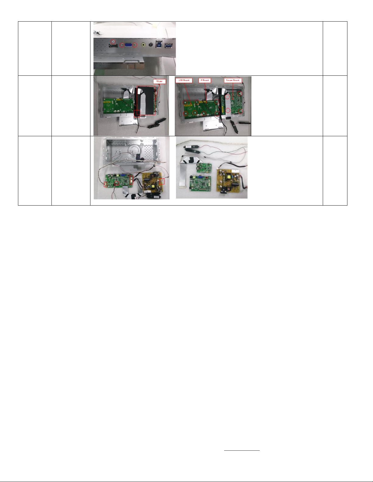
Unlock the
screw and 2
bolts.
Ph2 Cross
Screwdriver
and Six corner
sleeve
Screwdriver
Take away
the ACE
Tape and
Mylar, then
unlock
the10
screws.
Ph2 Cross
Screwdriver
Take out
the Power
Board, USB
Board and
IF Board
from
Chassis,
and then
separate all
cables from
connectors.
N/A
EL-MF877-00 Page 4
Template Revision B
PSG instructions for this template are available at EL-MF877-01
 Loading...