

Page 1

About this Manual
We’ve added this manual to the Agilent website in an effort to help you support
your product. This manual is the best copy we could find; it may be incomplete
or contain dated information. If we find a more recent copy in the future, we will
add it to the Agilent website.
Support for Your Product
Agilent no longer sells or supports this product. Our service centers may be able
to perform calibration if no repair parts are needed, but no other support from
Agilent is available. You will find any other available product information on the
Agilent Test & Measurement website, www.tm.agilent.com.
HP References in this Manual
This manual may contain references to HP or Hewlett-Packard. Please note that
Hewlett-Packard's former test and measurement, semiconductor products and
chemical analysis businesses are now part of Agilent Technologies. We have
made no changes to this manual copy. In other documentation, to reduce
potential confusion, the only change to product numbers and names has been in
the company name prefix: where a product number/name was HP XXXX the
current name/number is now Agilent XXXX. For example, model number
HP8648A is now model number Agilent 8648A.
Page 2

Installation Guide
Publication number E2494-92001
March 1998
Copyright Hewlett-Packard Company 1997, 1998
All Rights Reserved
HP E2494A Probe Adapter for
the Intel Pentium
®
II Mobile
Processor
Page 3
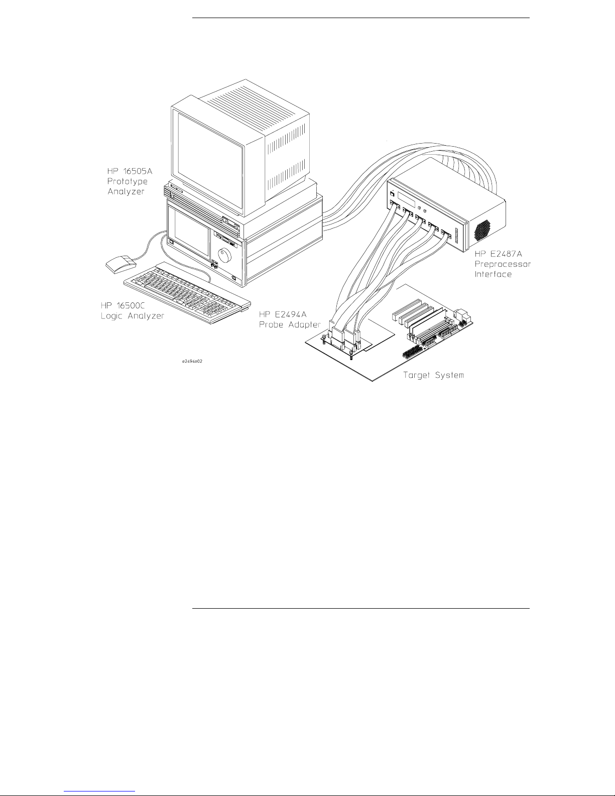
Installation at a Glance
This Installation Guide shows how to connect Hewlett-Packard’s
HP E2494A Probe Adapter to an Intel Mobile Pentium
This probe adapter provides a quick and reliable means of connecting
the HP E2487A Preprocessor Interface to supported target systems,
using the 190-pin Mictor connector. The supported target systems
include the Pentium II Instrumented Mobile Module, and the Pentium
II Mobile Processor mounted on Intel’s Instrumented Interposer board.
®
II processor.
Installation Overview
• Connect the preprocessor interface to the probe adapter.
• Connect the probe adapter to the target system 190-pin Mictor
connector, and adjust the adjustment screws.
Pentium® is a U.S. registered trademark of Intel Corporation.
2
Page 4
Equipment Supplied
• Probe adapter
• This Installation Guide
Minimum Equipment Required
• For target systems using a Pentium II Mobile Module, a Pentium II
Instrumented Mobile Module is required.
• For target systems using a Pentium II Mobile Processor, an
Instrumented Interposer board is required.
3
Page 5
CAUTION
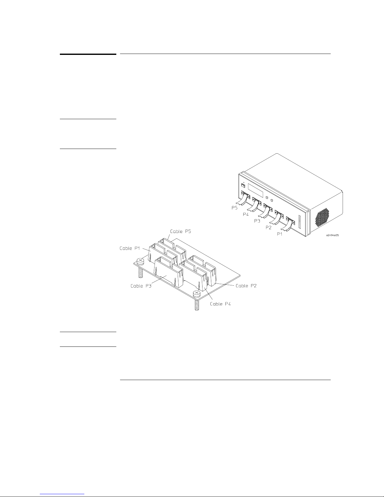
To connect the probe adapter to the HP E2487A Preprocessor Interface
To connect the probe adapter to the HP E2487A
Preprocessor Interface
The probe adapter has five high-density connectors, labeled Cable P1
through Cable P5. The HP E2487A Preprocessor Interface also has five
high-density cables, labeled P1 through P5. Connect the preprocessor cables
to the correspondingly-numbered probe adapter connectors.
To prevent equipment damage, you must connect the preprocessor interface
cables to the probe adapter before connecting the probe adapter to the
target system.
CAUTION
To prevent equipment damage, when disconnecting the preprocessor
interface from the probe adapter use the procedure on page 11.
4
Page 6

CAUTION
To connect to the target system
To connect to the target system
The HP E2494A probe adapter connects to both the Pentium II Instrumented
Mobile Module, and the Pentium II Mobile Processor mounted on Intel’s
Instrumented Interposer board, using the 190-pin Mictor connector. The
probe adapter connects to both types of target systems in a similar manner.
You must have the appropriate board for connecting the HP E2494 A to your
target system. For target systems using a Pentium II Mobile Module, a Pentium
II Instrumented Mobile Module is required. For target systems using a Pent ium
II Mobile Processor, an Instrumented Interpose r board is required. These
boards have the 190-pin Mictor connectors mounted on them. They are
available from Intel.
Connecting to Pentium II Instrumented Mobile Module systems
To protect your equipment, remove the power from both the preprocessor
interface and the target system before you make or break connections.
CAUTION
1
Remove the Pentium II Instrumented Mobile Module board from the
target system.
2 Connect the HP E2487A preprocessor interface cables to the
HP E2494A probe adapter, as shown on page 4.
Connecting the preprocessor interface cables to the probe adapter after the
probe adapter is already connected to the mobile module may exert
excessive stress on the mobile module and the probe adapter. Excessive
stress can damage the mobile module and/or the probe adapter.
5
Page 7

CAUTION
To connect to the target system
3 Plug the probe adapter into the 190-pin Mictor connector on the
Pentium II Instrumented Mobile Module, ensuring that Pin 1 is
properly aligned (see illustration below).
Damage to the connectors on the target system and probe adapter can result
from incorrect connection. Note the position of Pin 1 of the 190-pin Mictor
connectors on the probe adapter and the Instrumented Mobile Module board
prior to making any connection. Take care to align the probe adapter
connector with the pins on the Instrumented Mobile Module board
connector so that all pins are making contact. Also, ensure that the probe
adapter is firmly seated in the 190-pin Mictor connector, and that the probe
adapter is parallel within ±4° with the Pentium II Instrumented Mobile
Module.
Connecting the probe adapter to the Pentium II Instrumented Mobile Module board
4 Loosen the adjustment screws to ensure that there will be adequate
clearance once you connect the assembly to the target system.
6
Page 8

To connect to the target system
5 Attach the fully-connected probe adapter/Instrumented Mobile
Module assembly to the connectors on the mother board.
Connecting to the Pen tium II Instrumented Mobile Module target system
CAUTION
6 Adjust the screws until they are making contact with the mother
board. Ensure that the probe adapter is firmly seated in the 190-pin
Mictor connector, and that the probe adapter is parallel within ±4°
with the mother board (see below).
The adjustment screws must be properly adjusted so that they are touching
the mother board, and the probe adapter is parallel within ±4° with the
mother board. If the probe adapter is not supported by the adjustment
screws, or if the probe adapter is not seated so that it is parallel within ±4°
with the mother board, damage may occur to the Mictor connectors.
Required alignment for probe adapter and target system
7
Page 9

CAUTION
CAUTION
To connect to the target system
Connecting to the Pentium II Mobile Processor mounted on Intel’s
Instrumented Interposer board
To protect your equipment, remove the power from both the HP E2487A
Preprocessor Interface and the target system before you make or break
connections.
If you are already using an Instrumented Interposer board, remove
1
the Instrumented Interposer board from the target system. If you are
not already using an Instrumented Interposer board, remove the
microprocessor from the target system and plug it into the
Instrumented Interposer board.
2 Connect the HP E2487A preprocessor interface cables to the
HP E2494A probe adapter, as shown on page 4.
Connecting the preprocessor interface cables to the probe adapter after the
probe adapter is already connected to the interposer board may exert
excessive stress on the interposer board and the probe adapter. Excessive
stress can damage the interposer board and/or the probe adapter.
Loosen the adjustment screws to ensure that there will be adequate
3
clearance once you connect the probe adapter to the Instrumented
Interposer board.
8
Page 10

CAUTION
To connect to the target system
4 Plug the probe adapter into the 190-pin Mictor connector on the
Instrumented Interposer board (see illustration below).
Damage to the connectors on the target system and probe adapter can result
from incorrect connection. Note the position of Pin 1 of the 190-pin Mictor
connectors on the probe adapter and target system prior to making any
connection. Also, take care to align the probe adapter connector with the
pins on the target system connector so that all pins are making contact.
Connecting the probe adapter to the Instrumented Interposer board
9
Page 11

CAUTION
To connect to the target system
5 Adjust the adjustment screws until they are making contact with the
interposer board. Ensure that the probe adapter is firmly seated in
the 190-pin Mictor connector, and that the probe adapter is parallel
within ±4° with the interposer board (see illustration below).
The adjustment screws must be properly adjusted so that they are touching
the interposer board, and the probe adapter is parallel within ±4° with the
interposer board. If the probe adapter is not supported by the adjustment
screws, or if the probe adapter is not seated so that it is parallel within ±4°
to the interposer board, damage may occur to the Mictor connectors.
Required alignment for connecting probe adapter to Intel’s Instrumented Interposer board
6 Attach the fully-connected probe adapter/Instrumented Interposer to the
connectors on the mother board.
Connecting to the Instrumented Interposer target system
10
Page 12

CAUTION
To disconnect the preprocessor interface from the probe adapter
To disconnect the preprocessor interface from the
probe adapter
The Mictor connectors can be damaged by excessive stress. Always
disconnect using the reverse procedure as connecting. Disconnect the
assembly from the target system, then the probe adapter from the
instrumented board, then the preprocessor interface cables from the probe
adapter.
To protect your equipment, remove the power from both the HP E2487A
Preprocessor Interface and the target system before you make or break
connections.
Power requirements
The probe adapter draws a maximum 100 mA @ 5V, which is supplied by the
logic analyzer.
CAT I, Pollution degree 2.
This product is intended for indoor use only.
Cleaning
Remove any dust or debris from the probe adapter with precision dusting
cleaner (otherwise known as inert dusting gas or compressed air).
Replaceable parts
The repair strategy for this probe is product replacement.
11
Page 13

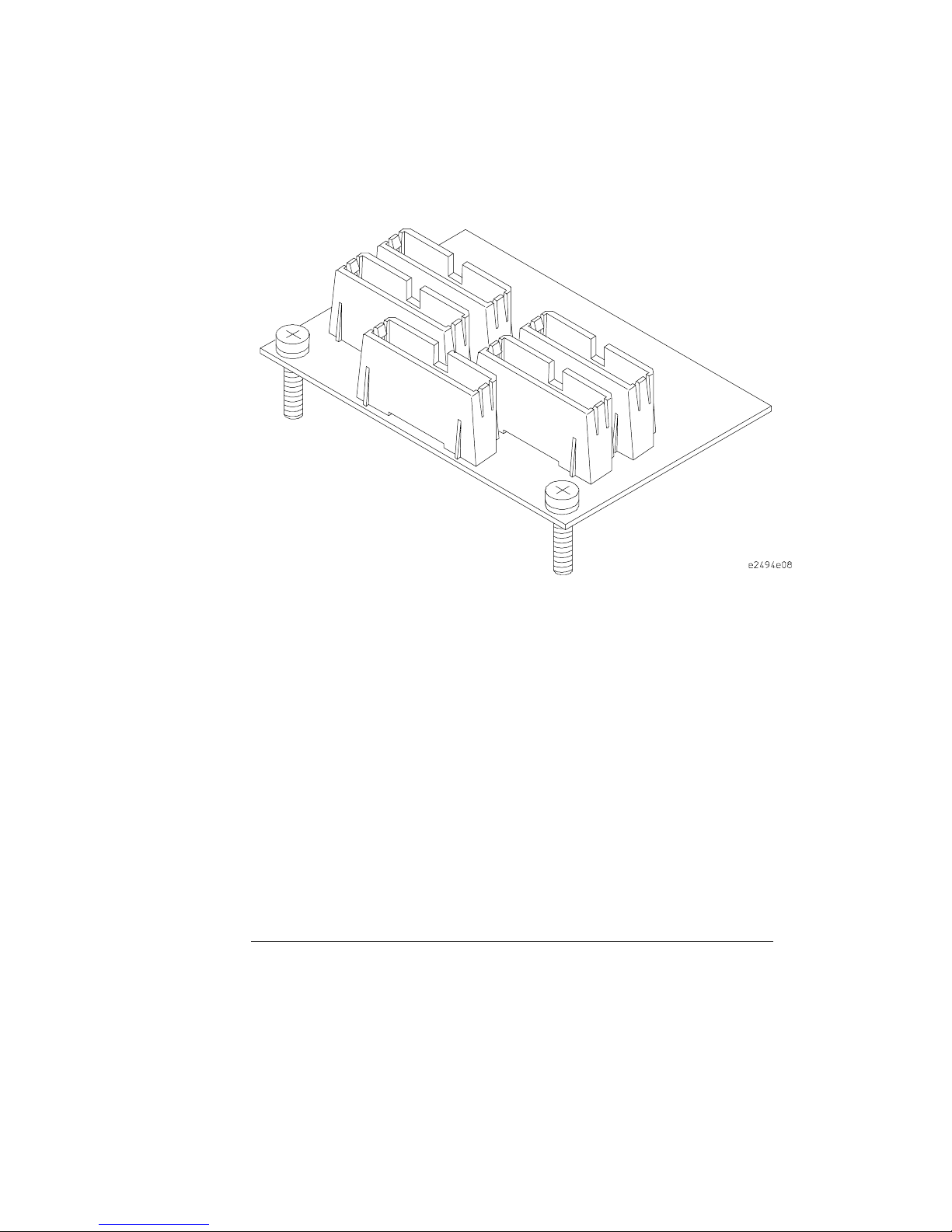
Probe dimensions
Probe dimensions
The figure below gives the dimensions for the HP E2494A Probe Adapter.
The dimensions are listed in inches and millimeters.
Dimensions
12
Page 14

© Copyright HewlettPackard Company 1997, 1998
All Rights Reserved.
Reproduction, adaptation, or
translation without prior
written permission is
prohibited, except as allowed
under the copyright laws.
Restricted Rights Legend
Use, duplication, or
disclosure by the U.S.
Government is subject to
restrictions set forth in
subparagraph (C) (1) (ii)
of the Rights in Technical
Data and Computer Software
Clause in DFARS
252.227-7013.
Hewlett-Packard Company,
3000 Hanover Street, Palo
Alto, CA 94304 U .S.A.
Rights for non-DOD U.S.
Government Departments
and Agencies are set forth in
FAR 52.227-19(c)(1,2).
Document Warranty
The information contained in
this document is subject to
change without notice.
Hewlett-Packard makes
no warranty of any k ind
with regard to this
material, including, but
not limited to, the implied
warranties of
merchantability or fitness
for a particular purpose.
Hewlett-Packard shall not be
liable for errors contained
herein or for damages in
connection with the
furnishing, performance, or
use of th is material.
Safety
This apparatus has been
designed and tested in
accordance with IEC
Publication 348, Safety
Requirements for Measuring
Apparatus, and has been
supplied in a safe condition.
This is a Safety Class I
instrument (provided with
terminal for protective
earthing). Before applying
power, verify that the correct
safety precautions are taken
(see the following warnings).
In addition, note the external
markings on the instrument
that are described under
"Safety Symbols."
Warning
• Service instructions are for
trained service personnel. To
avoid dangerous electric
shock, do not perform any
service unless qualified to do
so. Do not attempt internal
service or adjustment unless
another person, capable of
rendering first aid and
resuscitation, is present.
• Whenever it is likely that
the ground protection is
impaired, you must make the
instrument inoperative and
secure it against any
unintended operation.
• Do not operate the
instrument in the presence of
flammable gasses or fumes.
Operation of any electrical
instrument in such an
environment constitutes a
definite safety hazard.
• Do not install substitute
parts or perform any
unauthorized modification to
the instrument.
Safety Symbols
Instruction manual symbol:
the product is marked with
this symbol when it is
necessary for you to refer to
the instruction manual in
order to protect against
damage to the product.
Hazardous voltage symbol.
Earth terminal symbol: Used
to indicate a circuit common
connected to grounded
chassis.
WARNING
The Warning sign denotes a
hazard. It calls attention to a
procedure, practice, or the
like, which, if not correctly
performed or adhered to,
could result in personal
injury. Do not proceed
beyond a Warning sign until
the indicated conditions are
fully understood and met.
CAUTIO N
The Caution sign denotes a
hazard. It calls attention to
an operating procedure,
practice, or the like, which, if
not correctly performed or
adhered to, could result in
damage to or destruction of
part or all of the product. Do
not proceed beyond a
Caution symbol until the
indicated conditions are fully
understood or met.
Hewlett-Packard
P.O. Box 2197
1900 Garden of the Gods Road
Colorado Springs, CO 80901-2197, U.S.A.
Page 15

Product Warranty
This Hewlett-Packard system
product is warranted against
defects in material and
workmanship for a period of
one year from date of
purchase. During the
warranty period,
Hewlett-Packard Company
will, at its op tion, ei ther
repair or replace products
that prove to be defective.
Products must be returned to
a service facility designated
by HP.
For products returned to
Hewlett-Packard for warranty
service, the Buyer shall
prepay shipping charges to
Hewlett-Packard and
Hewlett-Packard shall pay
shipping charges to return
the product to the Buyer.
However, the Buyer shall pay
all shipping charges, duties,
and taxes for products
returned to Hewlett-Packard
from another country.
Hewlett-Packard warrants
that its software and firmware
designated by
Hewlett-Packard for use with
an instrument will execute its
programming instructions
when properly installed on
that instrument.
Hewlett-Packard does not
warrant that the operation of
the instrument software, or
firmware will be
uninterrupted or error free.
Limitation of Warranty
The foregoing warranty shall
not apply to defects resulting
from improper or inadequate
maintenance by the Buyer,
Buyer-supplied software or
interfacing, unauthorized
modification or misuse,
operation outside of the
environmental specifications
for the product, or improper
site preparation or
maintenance.
No other warranty is
expressed or implied.
Hewlett-Packard
specifically disclaims the
implied warranties of
merchantability or fitness
for a particular purpose.
Exclusive Remedies
The remedies provided herein
are the buyer’s sole and
exclusive remedies.
Hewlett-Packard shall not be
liable for any direct, indirect,
special, incidental, or
consequential damages,
whether based on contract,
tort, or any other legal theory.
Assistance
Product maintenance
agreements and other
customer assistance
agreements are available for
Hewlett-Packard products.
For any assistance, contact
your nearest Hewlett-Packard
Sales Office.
Certification
Hewlett-Packard Company
certifies that this product met
its published specifications at
the time of shipment from the
factory. Hewlett-Packard
further certifies that its
calibration measurements are
traceable to the United States
National Institute of
Standards and Technology, to
the extent allowed by the
Institute’s calibration facility,
and to the calibration
facilities of other
International Standards
Organization members.
About this edition
This is the first edition of the
HP E2494A Probe Adapter
for the Intel Pentium II
Mobile Processor
Installation Guide.
Publication number
E2494-92001
Printed in USA.
Edition dates are as follows:
E2494-92000, Sept. 1997
E2494-92001, Mar. 1998
New editions are complete
revisions of the manual.
Many product updates do not
require manual changes and
manual corrections may be
done without accompanying
product changes. Therefore,
do not expect a one-to-one
correspondence between
product updates and manual
updates.
*E2494-92001*
*E2494-92001*
HP Part Number E2494-92001
Printed March, 1998
 Loading...