

Page 1
HP E2479A UPGRADE INSTALLATION PROCEDURES
MODEL 16500A-C OR 16500B-C
Tools Required:
l T10 Torx Screwdriver
l T15 Torx Screwdriver
l T25 Torx Screwdriver
l Posidrive Screwdriver
l Small Slot Head Screwdriver
l Long Nosed Pliers
Tools Recommended:
l Frame protector (HP part # 5040-7231) to protect front frame from damage
l
Padded work service to protect parts from breakage
l Double-sided foam tape (HP part # 0460-1992) for cable management
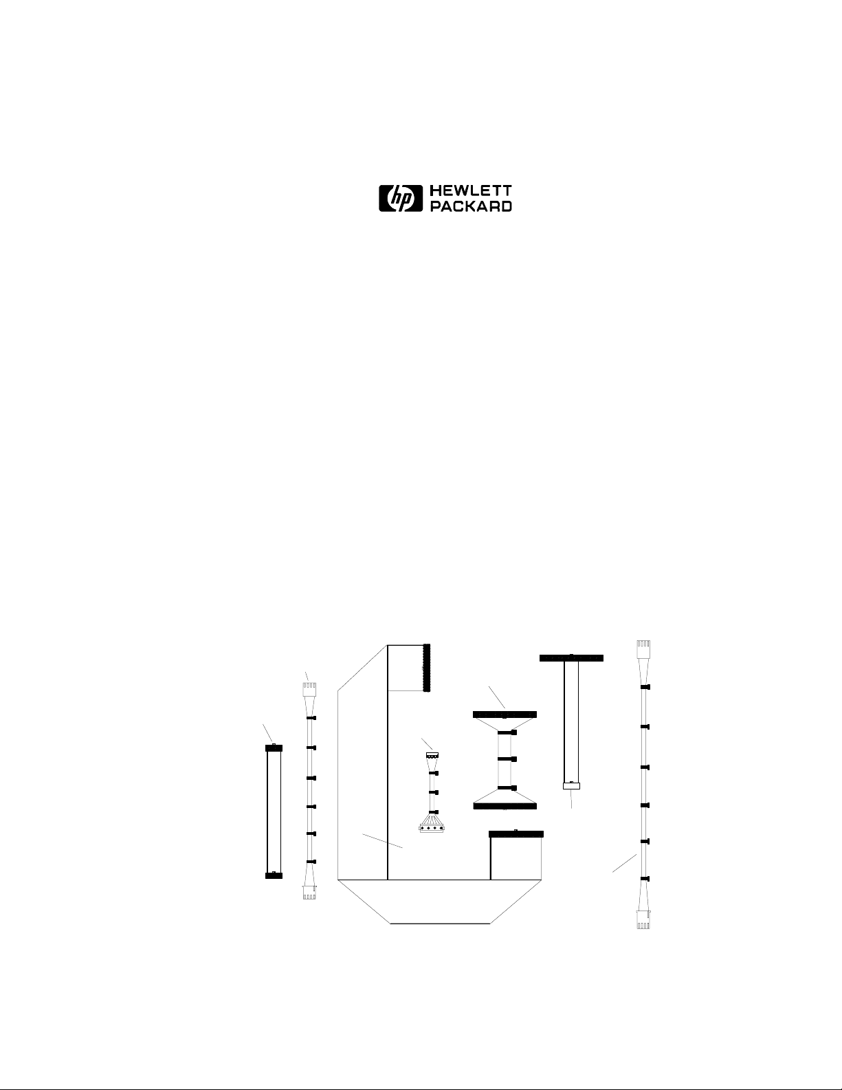
Cables included in the HP E2479A Upgrade Kit are shown below and listed in the
HP E2479A Upgrade Kit Parts List on page 3:
Video Control
10-pin
Front Panel
Cable
16500-61601
source: /std/16500/cables.pre freelance
Cable
16500-61605
Hard Disk
Drive
Power Cable
16500-61612
Flexible Disk
Drive Cable
16500-61609
Hard Disk
Drive
Data Cable
16500-61611
Video Signal
Cable
16500-61613
(10 x40)
Flexible Disk
Drive Power
Cable
16500-61622
HP E2479A Upgrade Procedures 1
Page 2
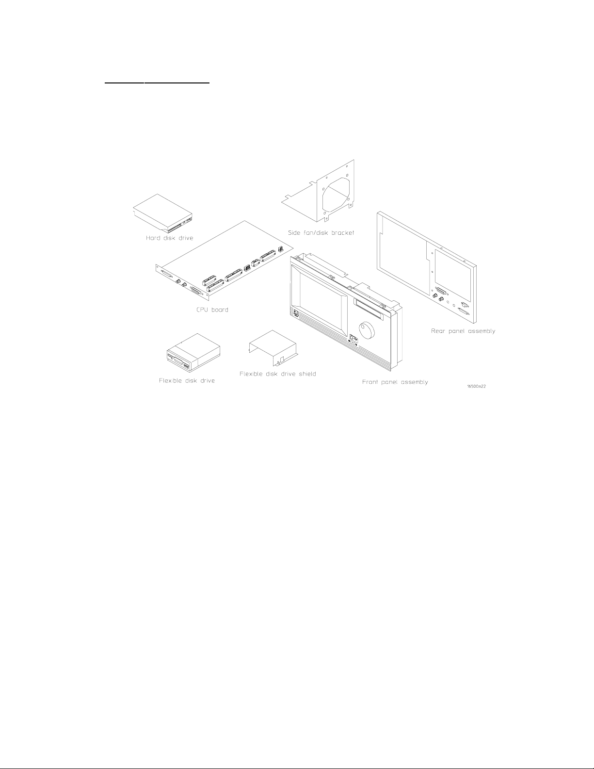
E2479A Upgrade Kit
The E2479A Upgrade Kit contains the following new assemblies, parts, and cables.
Part numbers for this kit are listed in the 16500C Upgrade Parts List table.
HP E2479A Upgrade Procedures 2
Page 3

Assembly/Part
HP E2479A UPGRADE KIT PARTS LIST
16500A 16500B 16500C Description Step
Front Panel Assembly discard
Front Panel 10-Pin Cable discard 16500-61601 16500-61601 Connects motherboard to front panel assembly 7
Video Control Cable discard 16500-61605 16500-61605 Connects front panel to color monitor 7
Rear Panel Assembly discard discard 16500-60203 New assembly for Model C 3
Side Fan Bracket Assembly discard discard 16500-01214 Attaches to side fan to frame 4
Flexible Disk Drive discard discard 0950-2656 New part for Model C 13
Rear Floppy Drive discard N/A N/A In Model A only
Flexible Disk Drive Cable discard 16500-61609 16500-61609 Connects to flex. disk drive and to CPU board 12
Flexible Disk Drive Power
Cable
Flexible Disk Drive Shield N/A discard 16500-00606 New shield for Model C 12
Hard Disk Drive N/A discard 0950-2983 New drive for Model C 5
Hard Disk Drive Data Cable N/A 16500-61611 16500-61611 Connects to hard disk drive and to CPU board 5
Hard Disk Drive Power Cable N/A 16500-61612 16500-61612 Connects to hard disk drive and CPU board 5
N/A N/A 16500-61622 Connects to flexible disk drive and CPU board 12
discard
16500-60202 New assembly for Model C 7
CPU Board Assembly discard discard 16500-66524 New board for Model C (includes pre-installed LAN
module
Video Signal Cable (10x40) discard 16500-61613 16500-61613 Connects to color monitor and CPU board 8
HP E2479A Upgrade Procedures 3
7
Page 4
Disassembly Procedure:
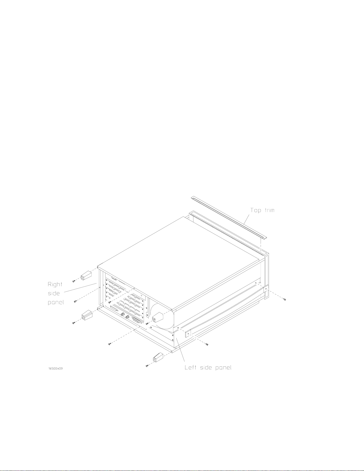
(See Figure 1 for Steps 1-6: Removing Outer Trim, Covers, and Panels)
1. Remove top trim from top front frame, using a small, flat blade screwdriver.
2. Remove 4 rear feet using a T10 Torx screwdriver.
3. Remove top cover using a T15 Torx screwdriver (one screw, at top of rear cover. Note that a
Posidrive screw was used on earlier units). Lift cover up and lift out.
4. Remove center screw in right side panel, using a T15 Torx (Note that a Posidrive screw was
used on earlier units).
5. Remove handle caps and handle straps from left side panel (1 screw on each end) using a T25
Torx screwdriver. Panel slides out.
6. Remove center screw in bottom panel and slide panel out.
ALL OF THE ABOVE PARTS WILL BE USED FOR REASSEMBLY
Figure 1. Removing Outer Trim, Covers, and Panels
HP E2479A Upgrade Procedures 4
Page 5
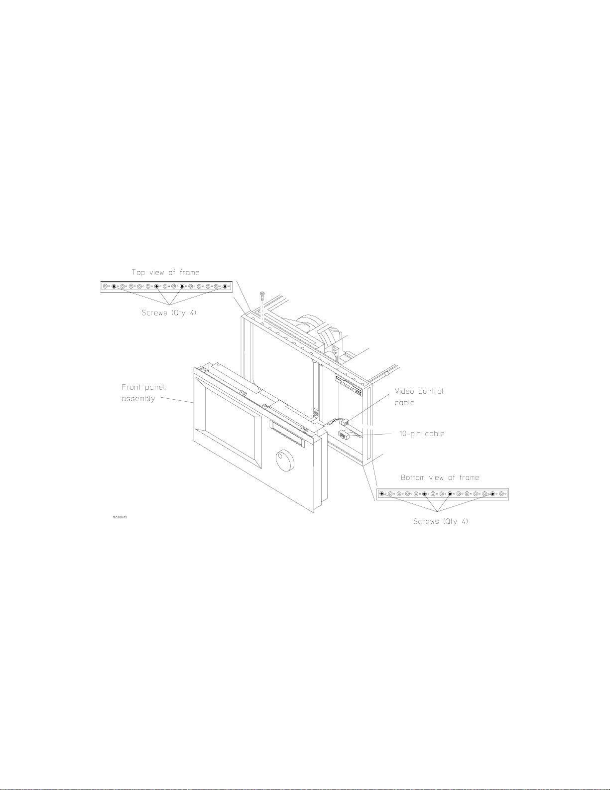
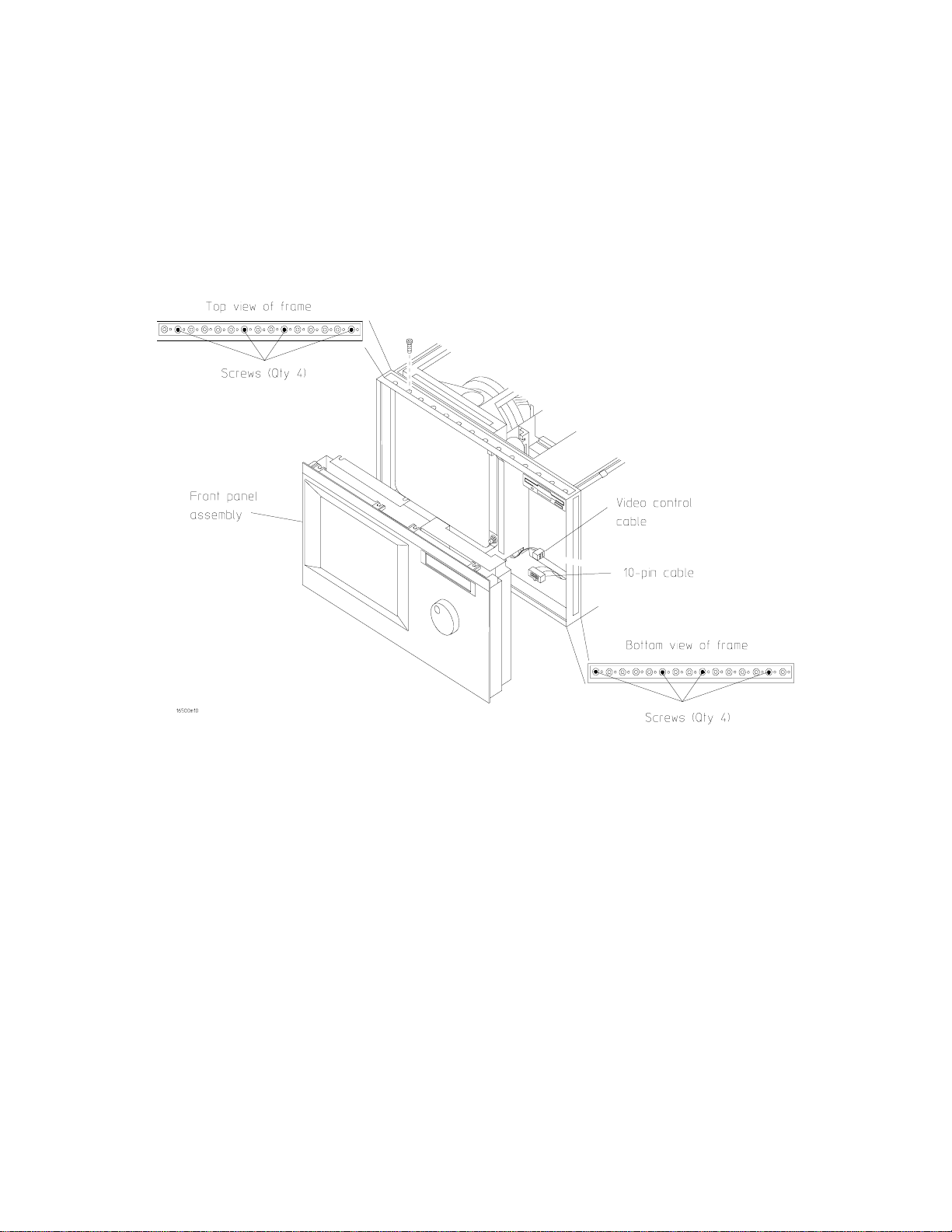
(See Figure 2 for Step 7: Removing the Front Panel Assembly)
7. Remove front panel assembly including the thin metal shield. The assembly will not be
reused.
a. Remove 4 screws from top of front panel assembly with T15 Torx screwdriver.
b. Turn unit over.
c. Remove 4 screws from bottom of front panel assembly.
d. Disconnect 10-pin and Video Control Cable.
e. Remove front panel assembly.
f. Turn unit over (right side up).
Figure 2. Removing the Front Panel Assembly
HP E2479A Upgrade Procedures 5
Page 6
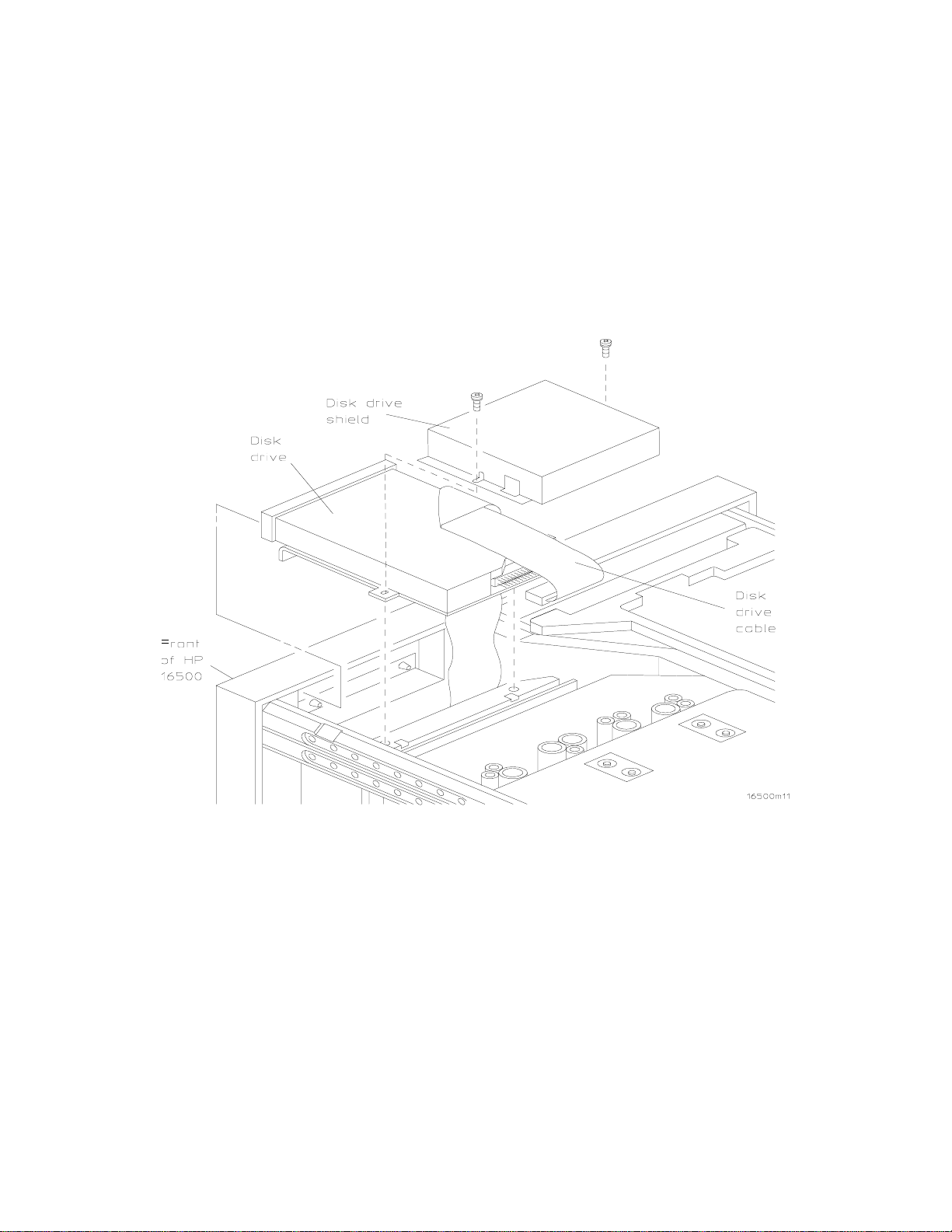
(See Figure 3 for Step 8: Removing the Front Disk Drive and Shield)
8. Remove front disk drive and disk drive shield. Disk drive and shield will not be reused.
a. Remove disk drive shield (2 screws) with a T10 Torx screwdriver. Save screws for
reassembly.
b. Disconnect disk drive cable located at rear of disk drive.
c. Remove disk drive.
Figure 3. Removing the Front Disk Drive and Shield
HP E2479A Upgrade Procedures 6
Page 7
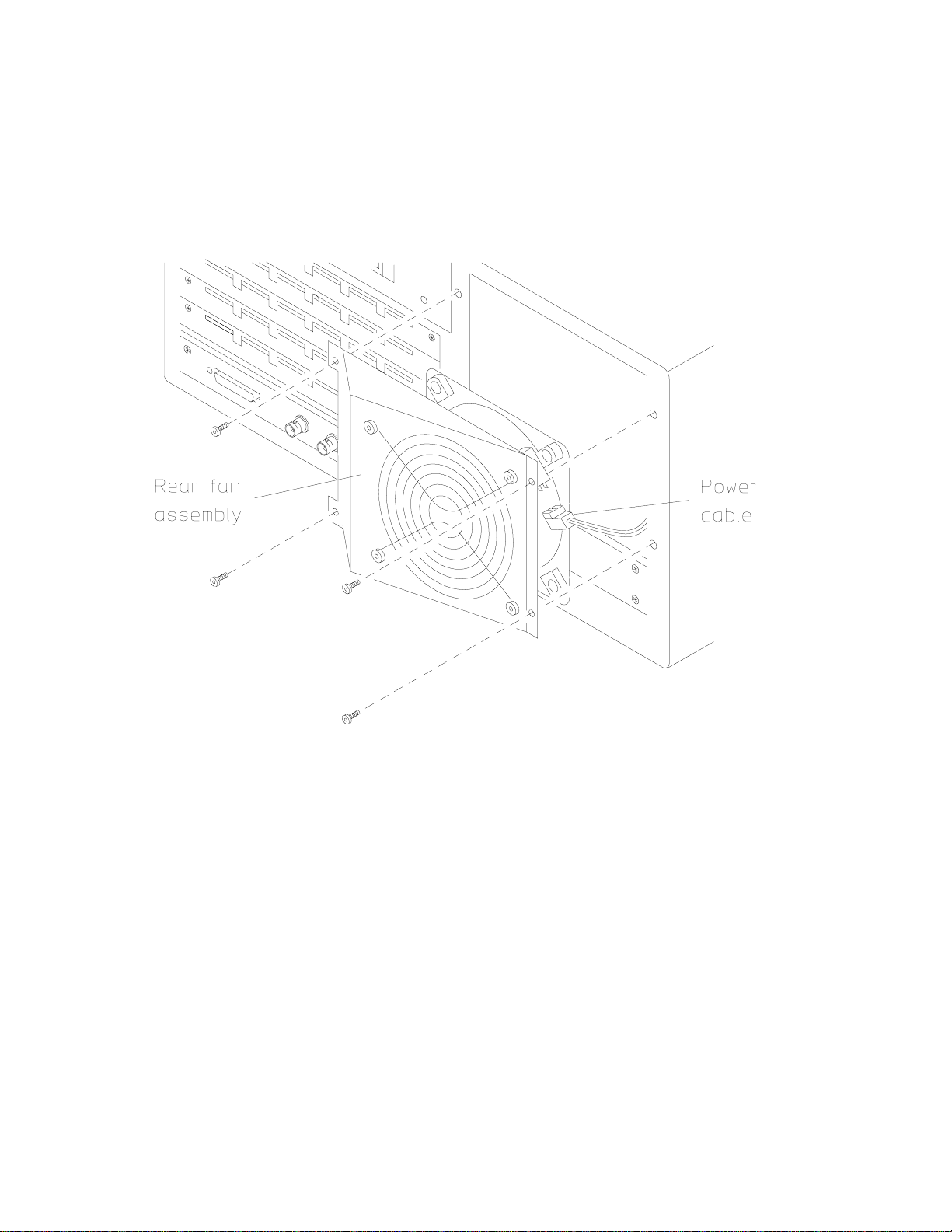
(See Figure 4 for Step 9: Removing the Rear Fan Assembly)
9. Remove rear fan assembly (4 screws, left and right sides) using a T10 Torx screwdriver.
Disconnect (sideways) power cord to fan (may require pliers). Save screws and fan assembly
for reassembly. Will be reused.
Figure 4. Removing the Rear Fan Assembly
HP E2479A Upgrade Procedures 7
Page 8
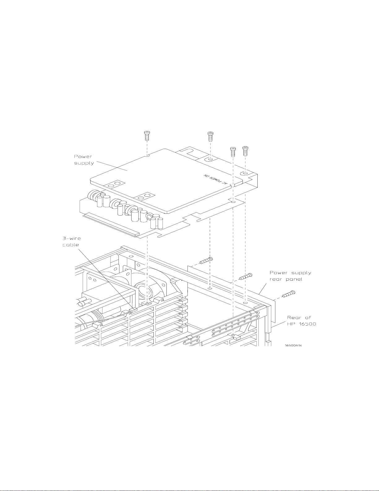
(See Figure 5 for Steps 10-11: Removing the Power Supply Rear Panel and Power
Supply)
10. Remove power supply rear panel (3 screws located by On/Off Switch), using a T10 Torx
screwdriver. Save for reassembly.
11. Remove power supply (4 screws, 2 in rear frame and 2 in bottom board of power supply)
using a T15 Torx screwdriver (slide toward rear of unit, lift up, then slide toward front of
unit). Disconnect 3-wire (5-pin) cable assembly at power supply end. Save for reassembly.
Figure 5. Removing the Power Supply Rear Panel and Power Supply
HP E2479A Upgrade Procedures 8
Page 9

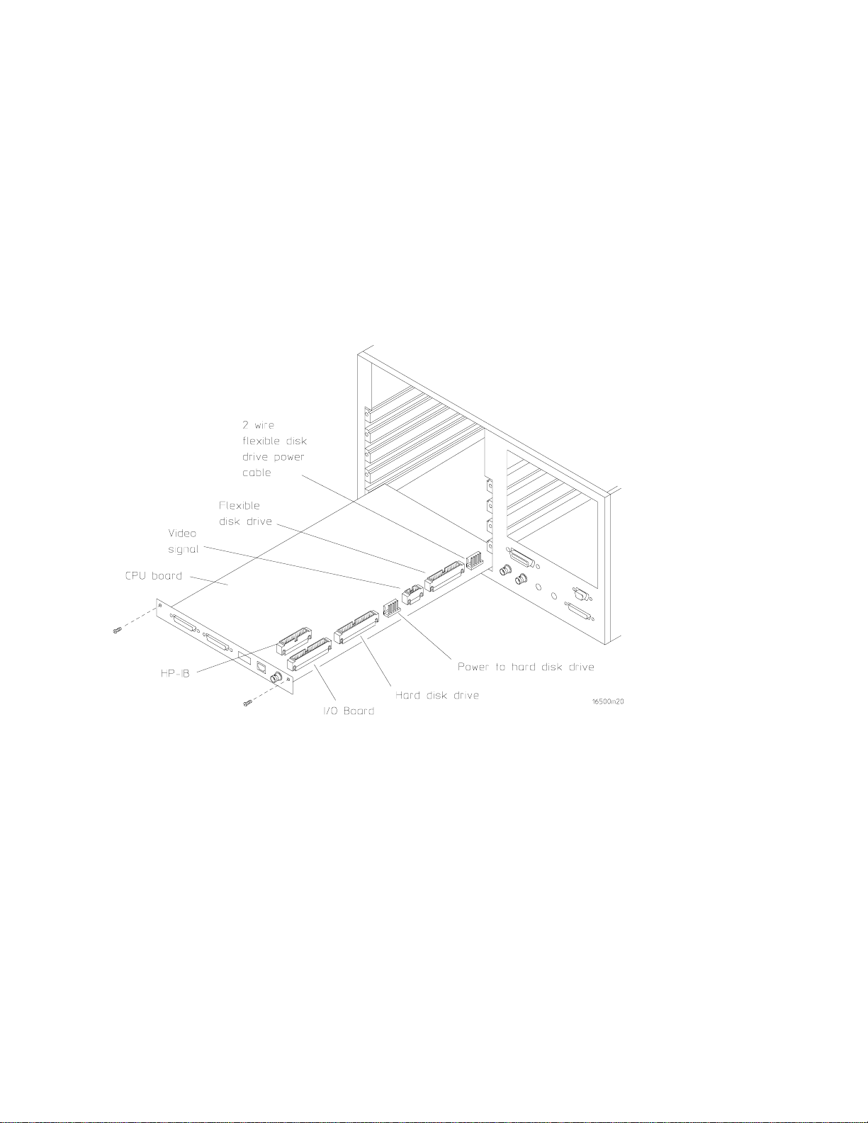
(See Figure 6 for Steps 12-13: Removing CPU cables and CPU Module)
12. Disconnect the following cables from the CPU board: video signal, flexible disk drive, hard
disk drive, and hard disk drive power cables (Model B only). If you have a LAN option,
remove LAN cable.
13. Remove CPU module (2 screws) using a T10 Torx screwdriver. Pull back and slide out CPU
module board. Save screws. CPU module will not be reused.
Figure 6. Removing the CPU Cables and CPU Module
HP E2479A Upgrade Procedures 9
Page 10

(See Figure 7 for Step 14: Removing the 10-Pin Cable from the Motherboard)
14. Remove 10-pin cable that goes from motherboard to front panel assembly. Cable will not be
reused.
Figure 7. Removing the 10-Pin Cable from the Motherboard
HP E2479A Upgrade Procedures 10
Page 11

(See Figure 8 for Step 15: Removing 4-Pin Video Control Cable)
(Model A only)
15. Remove 4-pin video control cable (pops out) (Model A only) that goes from side of monitor
to front panel. Cable will not be reused.
Figure 8. Removing the 4-Pin Video Control Cable (Model A only)
16. Remove ribbon cable that connects front and rear disk drive
be reused.
HP E2479A Upgrade Procedures 11
(Model A only).
Cable will not
Page 12

(See Figure 9 for Steps 17-20: Removing Side Fan and Fan/Disk Drive Bracket)
17. Remove side fan (4 screws) using a T15 Torx screwdriver. Unscrew fan and disconnect
power plug (may require pliers). Save fan and screws.
18. If you have a rear flexible disk drive (Model A), remove 4 screws using a T10 Torx
screwdriver and remove the rear flexible disk drive.
19. If you have a LAN option (Model B), remove the card (4 screws below fan opening and 2
screws on card inside) using a T10 Torx screwdriver. Disconnect cables and slide out. Card
and cables will not be reused.
20. Remove side fan/disk drive bracket (6 screws) using a T10 Torx screwdriver. Pull bracket
and slide out. Bracket will not be reused.
Figure 9. Removing Side Fan and Fan/Disk Drive Bracket
HP E2479A Upgrade Procedures 12
Page 13

(See Figure 10 for Step 21: Removing Hard Drive)
(Model B only)
21. Remove the hard drive (Model B only) (4 screws) from under the fan/disk bracket.
Disconnect data and power cables.
Figure 10. Removing Hard Drive
22. Remove rear panel (9 screws - keep in two groups for reassembly) using a T10 or T15 Torx
screwdriver. Rear panel will not be reused. Screws are shown in Figure 9.
HP E2479A Upgrade Procedures 13
Page 14

(Refer to Figure 11 for Step 23: Removing Video Signal Cable)
23. Remove video signal cable (10x40) from rear of monitor. Cable will not be reused.
Figure 11. Removing Video Signal Cable
HP E2479A Upgrade Procedures 14
Page 15

Reassembly Procedure:
(See Figure 1 for Steps 1-2: Connecting Video Signal and 4-pin Video Control Cables)
1. Connect video signal cable (10x40) to rear of monitor and feed through bottom slot of central
rib, third slot from rear.
Figure 1. Connecting the Video Signal and 4-Pin Video Control Cables
2. Connect 4-pin video-control cable to side area of monitor board.
HP E2479A Upgrade Procedures 15
(Model A-C only).
Page 16

(See Figure 2 for Steps 3-4: Installing Rear Panel, Fan/Disk Drive Bracket, and Side
Fan)
3. Attach prefabbed rear panel (new panel in Upgrade Kit). Panel should come with cover
plate attached, 5 grounding fingers in place, cables attached. Make sure panel is aligned with
plastic locators in card guides before tightening screws.
a. Line panel up with plastic tabs, left side first. Using a T15 Torx screwdriver, align 6
screws (4 on bottom and 2 on top of frame) with tabs, and tighten to 18 in-lbs.
b. Align 3 plasitight T10 screws in center of panel with tabs, and torque to 18 in-lbs.
4. Install fan/disk drive bracket (insert tabs into tab slots) and side fan.
a. Attach bracket to frame (4 screws), using a T10 Torx screwdriver.
b. Connect power plug to side fan and note the polarity on the cable and fan.
c. Install side fan (4 screws), using a T15 Torx screwdriver.
d. Feed cables through rear fan window.
Figure 2. Installing Rear Panel, Fan/Disk Drive Bracket, and Side Fan
HP E2479A Upgrade Procedures 16
Page 17

(See Figure 3 for Step 5: Installing Hard Drive Cables and Hard Drive)
5. Connect the hard disk drive data cable and power cable to the new hard disk drive. On the
40-pin hard disk drive data cable, the end that connects to the hard disk drive is the end that
contains the keying on cable side of connector. Outside keying end will connect to CPU
board. Install hard drive (4 screws), using a T10 Torx screwdriver. Feed cables from hard
drive through bottom slot of central rib, second slot from rear.
Figure 3. Installing Hard Drive Cables and Hard Drive
HP E2479A Upgrade Procedures 17
Page 18

(See Figure 4 for Step 6: Connecting 10-Pin Cable to Motherboard)
6. Connect 10-pin cable to motherboard and feed toward front of unit.
Figure 4. Connecting 10-Pin Cable to Motherboard
HP E2479A Upgrade Procedures 18
Page 19
(See Figure 5 for Steps 7-8: Installing CPU Board and Cables)
7. Install new CPU board (2 screws) using a T10 Torx screwdriver.
8. Connect the following cables to the CPU board: flexible disk drive cable, hard disk drive data
cable, video signal cable from monitor, hard disk drive 40-pin signal/data cable, power cable
to hard disk drive, I/O cable, HP-IB cable, and 2-wire cable providing power to front flexible
disk drive.
a. Remove strain relief from HP-IB cable.
b. Feed power cable to front flexible disk drive through bottom of central rib slot and
toward bottom of unit. Feed cable upwards. Feed all CPU board cables through bottom
slot of central rib.
Figure 5. Installing CPU Board and Cables
HP E2479A Upgrade Procedures 19
Page 20

(See Figure 6 for Steps 9-10: Installing Power Supply and Power Supply Rear Panel)
9. Connect 3-wire (5-pin) monitor cable to power supply. Install power supply by moving
power supply towards rear of unit, move board down and forward to connect pins to pin
connections on motherboard. Attach power supply (4 screws) using a T15 torx screwdriver.
10. Install power supply rear panel (3 screws located by On/Off Switch), using a T10 Torx
screwdriver.
Figure 6. Installing Power Supply and Po wer Supply Rear Panel
HP E2479A Upgrade Procedures 20
Page 21

(See Figure 7 for Step 11: Installing Rear Fan Assembly)
11. Connect (sideways) power cable to fan assembly. Install Rear Fan Assembly (4 screws, left
and right sides) using a T10 Torx screwdriver.
Figure 7. Installing Rear Fan Assembly
HP E2479A Upgrade Procedures 21
Page 22

(See Figure 8 for Steps 12-13: Installing Flexible Disk Drive, Disk Drive Shield, and
Cables)
12. Connect 34-pin ribbon cable and power cable to new flexible disk drive. Install disk drive
shield over flexible disk drive. Fold the flexible disk drive cable and the disk drive power
cables and position them forward on top of disk drive.
Figure 8. Installing Flexible Disk Drive, Disk Drive Shield, and Cables
13. Install flexible disk drive. The front of the disk drive is inserted through the front panel.
Make sure cables are not pinched or squeezed and front of disk drive is aligned at front of
panel. Using a T10 screwdriver, (2 screws) attach drive firmly.
HP E2479A Upgrade Procedures 22
Page 23
(See Figure 9 for Step 14: Installing Front Panel Assembly)
14. Connect cables to new front panel assembly. Install new front panel assembly onto the front
of the mainframe and insert screws (8) in the holes indicated in Figure 9. Using a T15 Torx
screwdriver, tighten screws (8) to 5 in-lbs. Do not overtorque. You may need to press down
the back of the flexible disk drive to allow it to fit in the slot on the front panel assembly.
Ensure front panel is recessed in metal frame before tightening screws.
Figure 9. Installing Front Panel Assembly
HP E2479A Upgrade Procedures 23
Page 24

(See Figure 10 for Steps 15-21: Installing trim, covers, panels, and feet)
15. Install trim on top of front frame (presses in place).
16. Attach left side panel and handle straps (1 screw on each end), using a T25 Torx screwdriver.
17. Attach right side panel (position unit to view from front). Install screw at center of panel,
using a T15 Torx screwdriver.
18. Attach top cover using a T15 Torx screwdriver (1 screw at top of rear cover. Note that a
posidrive screw was used on earlier units).
19. Attach bottom panel (1 screw in center of panel). Panel slides in.
20. Install 4 rear feet using a T10 Torx screwdriver.
21. Place E2479A serial number label on side of rear fan assembly.
Figure 10. Installing Trim, Covers, Panels, and Feet
HP E2479A Upgrade Procedures 24
Page 25

Install 16500C Operating System:
l. Power up the HP 16500C. The mainframe self-test screen comes on. The flexible disk drive
test will yield a "No Disk" error message. The hard disk drive may fail the power-up self test
if the hard drive is not pre-formatted. See that the other power-up self tests pass.
Note: The hard disk drive delivered with the HP E2479A upgrade kit should be
pre-loaded with the operating system software. Proceed with steps 2-9 only if the
hard disk drive power-up self test fails.
2. Turn off the HP 16500C. Get Disk 1 of the operating system flexible disks from the disk
pouch that was included with the HP E2479A kit. Insert Disk 1 in the mainframe flexible
disk drive.
3. Again, power up the HP 16500C. The hard disk drive will fail the power-up self test because
the hard drive is not formatted. This time the HP 16500C System Configuration menu should
appear. For safety, push the flexible disk drive eject button to pop the flexible disk from the
drive mechanism.
4. Select Configuration, then at the pop-up menu select Hard Disk. Select Load, then at the
pop-up menu select Format Disk. Select Execute and Continue to begin formatting the hard
disk drive.
5. When formatting is complete, select Format Disk, then at the pop-up menu select Make
Directory. Then select the directory name field, and using the pop-up keypad type in the
directory name
SYSTEM. Select Execute.
6. Select Make Directory, then at the pop-up menu select Change Directory. The
SYSTEM
subdirectory appears in the directory name field. Select Execute.
7. Re-insert Disk 1 in the flexible disk drive. Select Hard Disk, then at the pop-up menu select
Flexible Disk.
8. Select Load, then at the pop-up menu select Copy. Enter *.* in the filename field. Select the
field on Flexible Disk, then at the pop-up menu select Hard Disk. Select Execute.
9. All of the files on each of the disks (operating system disks and PV system disk) in the disk
pouch are to be copied onto the hard disk drive in the
SYSTEM subdirectory.
TESTING
Run Performance Verification procedures found in the HP16500C Service Guide.
HP E2479A Upgrade Procedures 25
 Loading...