

Page 1

Table of Contents
HP E1563A and HP E1564A Digitizer
HEWLETT-PACKARD WARRANTY STATEMENT ..............................................3
Safety Symbols ...........................................................................................................4
WARNINGS.................................................................................................................4
Declaration of Conformity............................................................................................5
WARNINGS.................................................................................................................6
Reader Comment Sheet ................................................................................................7
Chapter 1
Digitizer Module Set-up ................................................................................................9
Using This Chapter.............................................................................. .........................9
Installing the Digitizer in a Mainframe.......................................................................15
Cable Connector Assembly Instructions.....................................................................20
Chapter 2
Digitizer Application Information ..............................................................................25
Using this Chapter ......................................................................................................25
Digitizer Block Diagrams...........................................................................................25
Power-on and Reset State...........................................................................................27
Triggering the Digitizer..............................................................................................29
Input Overload Condition...........................................................................................34
HP E1563A and E1564A Digitizer Application Examples........................................35
Chapter 3
Digitizer Command Reference ...................................................................................39
ABORt........................................................................................................................42
CALCulate..................................................................................................................43
CALibration................................................................................................................47
DIAGnostic.................................................................................................................55
FORMat......................................................................................................................63
INITiate.......................................................................................................................64
INPut...........................................................................................................................66
OUTPut.......................................................................................................................68
[SENSe:].....................................................................................................................70
SAMPle.......................................................................................................................78
STATus.......................................................................................................................83
SYSTem......................................................................................................................87
TEST...........................................................................................................................88
TRIGger......................................................................................................................94
IEEE 488.2 Common Command Quick Reference..................................................100
Contents 1
Page 2

Appendix A
HP E1563A and E1564A Digitizer
Specifications ..............................................................................................................111
Appendix B
HP E1563A and E1564A
Register-Based Programming ...................................................................................113
About This Appendix................................................................................................113
Register Addressing..................................................................................................113
Register Descriptions................................................................................................116
Program Timing and Execution................................................................................130
Appendix C
HP E1563A and E1564A Digitizer
Error Messages ..........................................................................................................139
Execution Errors.......................................................................................................139
Self-Test Errors.........................................................................................................144
Calibration Errors .....................................................................................................144
Appendix D
HP E1563A and E1564A
Verification Tests .......................................................................................................145
Introduction...............................................................................................................145
Verification Tests......................................................................................................146
Performance Verification Test Programs .................................................................146
Functional Test .........................................................................................................147
Performance Verification.......................................... ......... .......................................148
Performance Test Record................................. ......... ................................................152
Appendix E
HP E1563A and E1564A
Adjustments ................................................................................................................157
Introduction...............................................................................................................157
Adjustment Procedures.............................................................................................158
2 Contents
Page 3

HEWLETT-PACKARD WARRANTY STATEMENT
HP PRODUCT: HP E1563A 2-Channel/E1564A 4-Channel Digitizer DURATION OF WARRANTY: 3 years
1. HP warrants HP hardware, accessori es and supplies against defects in materials and workmanship for the period specified above. If
HP receives notice o f such defects during the warranty peri od, HP will, at its option, either repair or replace products which prove to be
defective. Replacement products may be either new or like-new.
2. HP warrants that HP software will not fail to execut e its programming instructions, for the period specified above, due to defects in
material and workmanship when properly installed and used. If HP receives notice of such defe cts during the warranty period, HP will
replace software media which does not execute its programming instructions due to such defects.
3. HP does not warrant that the operation of HP products will be interrupted or error free. If HP is unable, within a reasonable time, to
repair or replace any product to a condition as warranted, customer will be entitled to a refund of the purchase price upon prompt return
of the product.
4. HP products may con tain remanufactured parts equivalent to new in performance or may have been subject to incidental use.
5. The warranty period begins on the date of delivery or on the date of installation if installed by HP. If customer schedules or dela ys HP
installation more than 30 days after delivery, warranty begins on the 31st day from delivery.
6. Warranty does not apply to defects resulting from (a) improper or inadequate maintenance or calibration, (b) software, interfacing, parts
or supplies not supplied by HP, (c) unauthorized modification or misuse, (d) operation outside of the published environmental
specifications for the product, or (e) improper site preparation or maintenance.
7. TO THE EXTENT ALLOWED BY LOCAL LAW, THE ABOVE WARRANTIES ARE EXCLUSIVE AND NO OTHER
WARRANTY OR CONDITION, WHETHER WRITTEN OR ORAL, IS EXPRESSED OR IMPLIED AND HP SPECIFICALLY
DISCLAIMS ANY IMPLIED WARRANTY OR CONDITIONS OF MERCHANTABILITY, SATISFACTORY QUALITY, AND
FITNESS FOR A PARTICULAR PURPOSE.
8. HP will be liable for damage to tangible property per incident up to the greater of $300,000 or the actual amount paid for the product
that is the subject of the claim, an d for damages for bodily injury or death, to the extent that all su ch damages are determined by a court
of competent jurisdiction to have been directly ca used by a defective HP product.
9. TO THE EXTENT ALLOWED BY LOCAL LAW, THE REMEDIES IN THIS WARRANTY STATEMENT ARE CUSTOMER’S
SOLE AND EXLUSIVE REMEDIES. EXCEPT AS INDICATED ABOVE, IN NO EVENT WILL HP OR ITS SUPPLIERS BE
LIABLE FOR LOSS OF DATA OR FOR DIRECT, SP ECIAL, INCIDENTAL, CONSEQUENTIAL (INCLUDING LOST PROFIT OR
DATA), OR OTHER DAMAGE, WHETHER BASED IN CONTRACT, TORT, OR OTHERWISE.
FOR CONSUMER TRANSACTIONS IN AUSTRALIA AND NEW ZEALAND: THE WARRANTY TERMS CONTAINED IN THIS
STATEMENT, EXCEPT TO THE EXTENT LAW FULLY PERM ITTED, DO NOT EXCLUDE, RESTRICT OR MODIFY AND AR E
IN ADDITION TO THE MANDATORY STATUTORY RIGHTS APPLICABLE TO THE SALE OF THIS PRODUCT TO YOU.
U.S. Government Restricted Rights
The Software and Documentation have been developed entirely at private expense. They are delivered and licensed as "commercial
computer software" as defined in DFARS 252.227- 7013 (Oct 1988), DFARS 252.211-7015 (May 1991) or DFARS 252.227-7014 (Jun
1995), as a "commercial item" as defined in FAR 2.101(a), or as "Restricted computer soft ware" as defined in FAR 52.227-19 (Jun
1987)(or any equivalent agency regulation or contract clause), whichever is applicable. You have only those rights provided for such
Software and Documentation by t he applicable FAR or DFARS clause or the HP standard software agreement for the product involved.
HP E1563A 2-Channel/E1564A 4-Channel Digitizer User's SCPI Programming Manual
Copyright © 1998 Hewlett-Packard Company. All Rights Reserved.
Edition 2
3
Page 4
or
Documentation History
All Editions and Updates of t his manu al and th eir creati on da te are list ed belo w. The first Edition of the m anual is Ed ition 1. The Edition
number increments by 1 whenever the manual is revised. Updates, which are issued between Editions, contain replacement pages to
correct or add additional information to the current Edition of the manual. Whenever a new Edition is created, it will contain all of the
Update information for the previous E dition. Each new Edition or Update also inc ludes a revised c opy of this do cumentation history page.
Edition 1 . . . . . . . . . . . . . . . . . . . . . . . . . . . . . . . . . . . . . . . . . . . . .October 1997
Edition 2 . . . . . . . . . . . . . . . . . . . . . . . . . . . . . . . . . . . . . . . . . . . . . . . April 1998
Safety Symbols
Instruction manual symbol affixed to
Instruction manual symbol affixed to
product. Indicates that the user must refer to
product. Indicates that the user must refer to
the manual for specific WARNING or
the manual for specific WARNING or
CAUTION information to av oid personal
CAUTION information to av oid personal
injury or damage to the product.
injury or damage to the product.
Indicates the field wiring te rminal that must
be connected to earth ground be fore
operating the equipmentÅprotects against
electrical shock in case of fault.
WARNING
Alternating current (AC)
Direct current (DC).
Indicates hazardous voltages.
Calls attention to a procedure, practice, or
condition that could cause bodily injury or
death.
Frame or chassis ground terminal —typically
connects to the equipment' s metal frame.
CAUTION
Calls attention to a procedure, practice, or
condition that coul d possibly cause damage to
equipment or perman ent loss of data.
WARNINGS
The following general safety precautions must be observed during all phases of operatio n, service, and repair of this product. Failure to
comply with these precautions or with specific warnings elsewhere in this manual violates safety standards of design, manufacture, and
intended use of the product. Hewlett-Packard Com pany assumes no liability for the customer's failure to comply with these requirements.
Ground the equipment: For Safety Class 1 equipment (equipment having a protective earth terminal), an uninterruptible safety earth
ground must be provided from the mains power source to the product input wiring terminals or supplied power cable.
DO NOT operate the product in an explosive atmosphere or in the presence of flammable gases or fumes.
For continued protection against fire, replace the line fuse(s) only with fuse(s) of the same voltage and current rating and type. DO NOT
use repaired fuses or short-circuited fuse holders.
Keep away from live circuits: Operating personnel must not remove equipment covers or shields. Procedures involving the removal of
covers or shields are for use by service-trained personnel only. Under certain conditions, dangerous voltages may exist even with the
equipment sw itche d off. To av oid danger ous ele ctric al sh ock, DO NOT perfor m pro cedure s inv olving cover or shi eld remova l unles s you
are qualified to do so.
DO NOT operate damaged equipmen t: Whenever it is possible that the safety protection features built into this product have been
impaired, either through physical damage, excessive mois ture, or any other reason, REMOVE POWER and do not use the product until
safe operation can be verified by service-trained personnel. If necessary, return the product to a Hewlett-Packard Sales and Service Office
for service and repair to ensure that safety features are maintained.
DO NOT service or adjust alone: Do not attempt internal service or adjustment unless another person, capable of rendering first aid and
resuscitation, is present.
DO NOT substitute parts or modify equipment: Becaus e of th e dang er of introd ucing addition al haz ards, do not i nstall subst itute pa rts
or perform any unauthorized modification to the product. Return the product to a Hewlett-Packard Sales and Service Office for service
and repair to ensure that safety features are maintained.
4
Page 5

Declaration of Conformity
according to ISO/IEC Guide 22 and EN 45014
Manufacturer’s Name: Hewlett-Packard Company
Loveland Manufacturing Center
Manufacturer’s Address: 815 14th street S.W.
Loveland, Colorado 80537
declares, that the product:
Product Name: 2-Channel and 4-Channel Digitizer
Model Number: HP E1563A and HP E1564A
Product Options: All
conforms to the following Product Specifications:
Safety: IEC 61010-1 (1990) Incl. Amend 2 (1996)/EN61010-1 (1993)
CSA C22.2 #1010.1 (1992)
UL 3111-1 (1994)
EMC: CISPR 11:1990/EN55011 (1991): Group 1, Class A
EN61000-3-2:1995 Class A
EN61000-3-3:1995
EN50082-1:1992
IEC 1000-4-2:1995 4kV CD, 8kV AD
IEC 1000-4-3:1995 3 V/m
IEC 1000-4-4:1995 1kV Power Line, 0.5kV Signal Lines
ENV50141:1993/prEN50082-1 (1995): 3 Vrms
EN61000-4-5:1995 1kV CM, 0.5kV DM
EN61000-4-8: 1993/prEN50082-1 (1995): 3 A/m
EN61000-4-11:1994/prEN50082-1 (1995): 30%,10ms 60%,100ms
Supplementary Information: The product herewith complies with the requirements of the Low Voltage Directive
73/23/EEC and the EMC Directive 89/336/EEC (inclusive 93/68/EEC) and carries the "CE" mark accordingly.
Tested in a typical configuration in an HP C-Size VXI mainframe.
November 15, 1997
European contact: Your local Hewlett-Packard Sales and Service Office or Hewlett-Packard GmbH, Depart-
ment HQ-TRE, Herrenberger Straße 130, D-71034 Böblingen, Germany (FAX +49-7031-14-3143)
Jim White, QA Manager
5
Page 6

WARNINGS
The HP E1563A and E156 4A Digitizers are capable of measuring voltages up to 256V maximum. Voltage levels above the levels
specified for accessible connectors or cable ends could cause bodily injury or death to an operator. Special precautions must be adhered
to (discussed below) when applying voltages in excess of 60 Vdc, 30 Vac rms or 42.4 Vac peak for a cont inuous, complex waveform.
Module connectors and test sign al cables connected to them cannot be operator accessibl e. Cables and connectors are considered
inaccessible if a tool (e.g., screwdriver, wrench, socket, etc.) or a key (equipment in a locked cabinet) is required to gain access to them.
Additionally, the operator cannot have access to a conductive surface connected to any cable conductor (High, Low or Guard).
Assure the equipment under test has adequate insulation between the cable connections and any operator-accessible parts (doors,
covers, panels, shields, cases, cabinets, etc.). Verify there are multiple and sufficient protective means (rated for the voltages you are
applying) to assure the operator will NOT come into contact with any energized conductor even if one of the protective means fails to
work as intended. For example, the inner side of a case, cabinet, door, cover or panel can be covered with an insulating material as well
as routing the test cables to the module’s front panel connectors through non-conductive, flexible conduit such as that used in electrical
power distribution.
6
Page 7
Please fold and ta pe for mailing
Reader Comment Sheet
HP E1563A 2-Channel and HP E1564A 4-Channel Digitizer User’s and SCPI Programming Manual
Edition 2
You can help us improve ou r manuals by s haring your commen ts and sug gestions. In appreciation of your time, we will
enter you in a quarterly drawing for a Hewlett-Packard Palmtop Personal Computer (U.S. government employees
are not eligible for the drawing).
Your Name
Company Name
Job Title
Address
City, State/Province
Country
Zip/Postal Code
Telephone Number with Area Code
Please list the system controller, operating system, programming language, and plug-in modules you are using.
fold here
BUSINESS REPLY MAIL
FIRST CLASS PERMIT NO. 37 LOVELAND, CO
POSTAGE WILL BE PAID BY ADDRESSEE
cut along this li ne
HEWLETT-PACKARD COMPANY
Measurement Systems Division
Learning Products Department
P.O. Box 301
Loveland, CO 80539-9984
NO POSTAGE
NECESSARY
IF MAILED
IN THE
UNITED STATES
fold here
Please pencil-in one circle for each statement below: Disagree Agree
• The documentation is well organized. OOOOO
• Instructions are easy to understand. OOOOO
The documentation is clearly written. OOOOO
•
Examples are clear and useful. OOOOO
•
• Illustrations are clear and helpful. OOOOO
The documentation meets my overall expectations. OOOOO
•
Please write any comments or suggestions below–be specific.
Page 8

Page 9

Note Your Digitizer may have experienced temperature extremes during ship-
Using This Chapter
Chapter 1
Digitizer Module Set-up
ment that can affect it’s calibration. It is recommened you perform a zero
offset calibration upon receipt using the
command for each channel to realize the accuracy specifications in
Appendix A. See Appendix E for the zero adjustment procedure.
This chapter pro vid es one page of general modul e information followed by
the tasks you must perform to set up your module and verify your
installation was successful. Chapter contents are:
CAL:ZERO<
•Adding DRAM (PC Memory SIMM) to the Module
•Setting the Module Address Switch
•Interrupt Line
•Input Terminals and Front Panel Indicators
•3-Wire and 2-Wi re Input Cabling Considerations
•Initial Operation
channel
>:ALL?
General Information The HP E1563A (2-channel) and HP E1564A (4-channel) are 800
kSample/second (14-bit resolution) digitizers capable of handling both
continuous and transient voltages up to 256V. They are ideal for
measurements in electomechanical design characterization, particularily in
environments with high levels of electrical noise. They are also ideal for
characterizing el ectronic and mechanic al trans ient wavef orms. You cannot
upgrade an E1563A 2-Channel to an E1564A 4-Channel Digitizer.
Both digitizers are designed to use PC SIMM memory. Memory sizes that
are supported are 4, 8, 16, 32, 64 and 128 Mbytes. The large memory can
easily capture tr ansients or act a s FIFO to allo w continuou s digiti zing while
unloading data with block mode transfers.
All channels sample simultaneously. The sample can be from an internal
clock derived from the internal time base or it can come from an external
source. Triggering ca n be set up for several sourc es with progra mmable pre
and post trigger reading counts. External time base, trigger and sample
inputs are provided on the front panel “D” subminiature connector.
Both the E1563A and E1564A digi tizers are re gister-based ins truments that
can be programmed at the regis ter le vel (regi ster programmin g infor mation
is covered in Appendix C) or at a higher level using SCPI or Plug&Play
drivers.
Digitizer Module Set-up 9
Page 10

Continuous voltages in a test set-up where the user has access to module
connectors and test signal cable ends are restricted to:
•60 Vdc
•30 Vac-rms
•42.4 Vac peak of a continuous, complex waveform
Continuous voltages in tes t set-ups where the module connector s and the test
signal cables connected to them are made non-accessible are:
•256 Vdc, 240 Vdc floating
•256 Vac peak
Transient voltages:
•Transient voltages are permitted providing the maximum amount of
charge transferred into a human body that contacts the voltage under
normal conditions, does not exceed 45 uCoulombs (45 uA-s).
Overload voltages (opens channel input relay):
Range V oltage Input Condition Vmax
62 mV to 4V High or Low to Guard >20V
4-channel and 2-channel
Module Differences
16V to 256V Low to Guard >40V
•The E1564A 4-Channel Digitizer has four selectable input filters per
channel (1.5 kHz, 6 kHz, 25 kHz and 100 kHz) that can be enabled.
•The E1563A 2-Channel Digitizer has a fixed 25 kHz input filter per
channel th at can be enabled.
•The E1564A 4-Channel Digitizer has a calibration bus output
(High, Low and Guard) and a programmable short.
•The E1563A 2-Channel Digitizer does not have a calibration bus
output however, a programmable short is provided for each channel.
An external calibration source must be provided for calibration.
The HP E1563A and E1564A Digitizers are c apable of measuring
voltages up to 256V maximum. Voltage levels above the levels
specified for accessible connectors or cable ends could cause
bodily injury or death to an oper ato r. Special precautions must
be adhered to (discussed below) when applying voltages in
excess of 60 Vdc, 30 Vac rms or 42.4 Vac peak for a continuous,
complex waveform.
Module connectors, and test signal cables connected to them,
must be made NON-accessible to an oper ator who has not bee n
told to access them: It is a supervisor’s res ponsibility t o advise
an operator that dangerous voltages exist when the operator is
instructed to access connectors and cables carrying these
10 Digitizer Module Set-up
Page 11

WARNING voltages. Making cables and connectors that carry hazardous
voltages inaccessible is a protective measure keeping an
operator from inadvertent or unknowing contact with these
harmful voltages. Cables and connectors are consi dered
inaccessible if a tool (e.g., screwdri ver, wrench, socket, etc.) or
a key (equipment in a locked cabinet) is required to gain access
to them. Additionally, the operator cannot have access to a
conductive surface connected to any cable conductor (High,
Low or Guard).
Assure the equipment under test has adequate insulation
between the cable connections and any operator-accessible
parts (doors, covers, panels, shields, cases, cabinets, etc.):
Verify there are multiple and sufficient protective means (rated
for the voltages you are applying) t o assure the operator will
NOT come into contact with any energized conductor even if
one of the protective means fails to work as intended. For
example, the inner side of a case, cabinet, door, cover or panel
can be covered with an insulating material as well as routing
the test cables to the module’s front panel connectors through
non-conductive, flexible conduit such as that used in electrical
power distribution.
WARNING Tighten the faceplate mounting screws after installing the
module in the mainframe to prevent electric shock in the case
of equipment or field wiring failure.
Caution To prevent equipment damage, do not connect this equipment
to mains or to any signal directly derived from mains.
Short-term temporary overvoltages must be limited to 500V or
less.
Caution To prevent equipment damage in the case of an overvoltage
condition, do not connect this equipment to any vol t age source
which can deliver greater than 2A at 500V in t he case of a fa ult.
If such a fault condition is possible, insert a 2A fuse in the input
line.
CLEANING THE FRONT PANEL AND TOP/BOTTOM SHIELDS:
Clean the outside surfaces of this module with a cloth slightly
dampened with water . Do not attempt t o clean the interior of th is
module.
Digitizer Module Set-up 11
Page 12
Adding RAM to the
Module
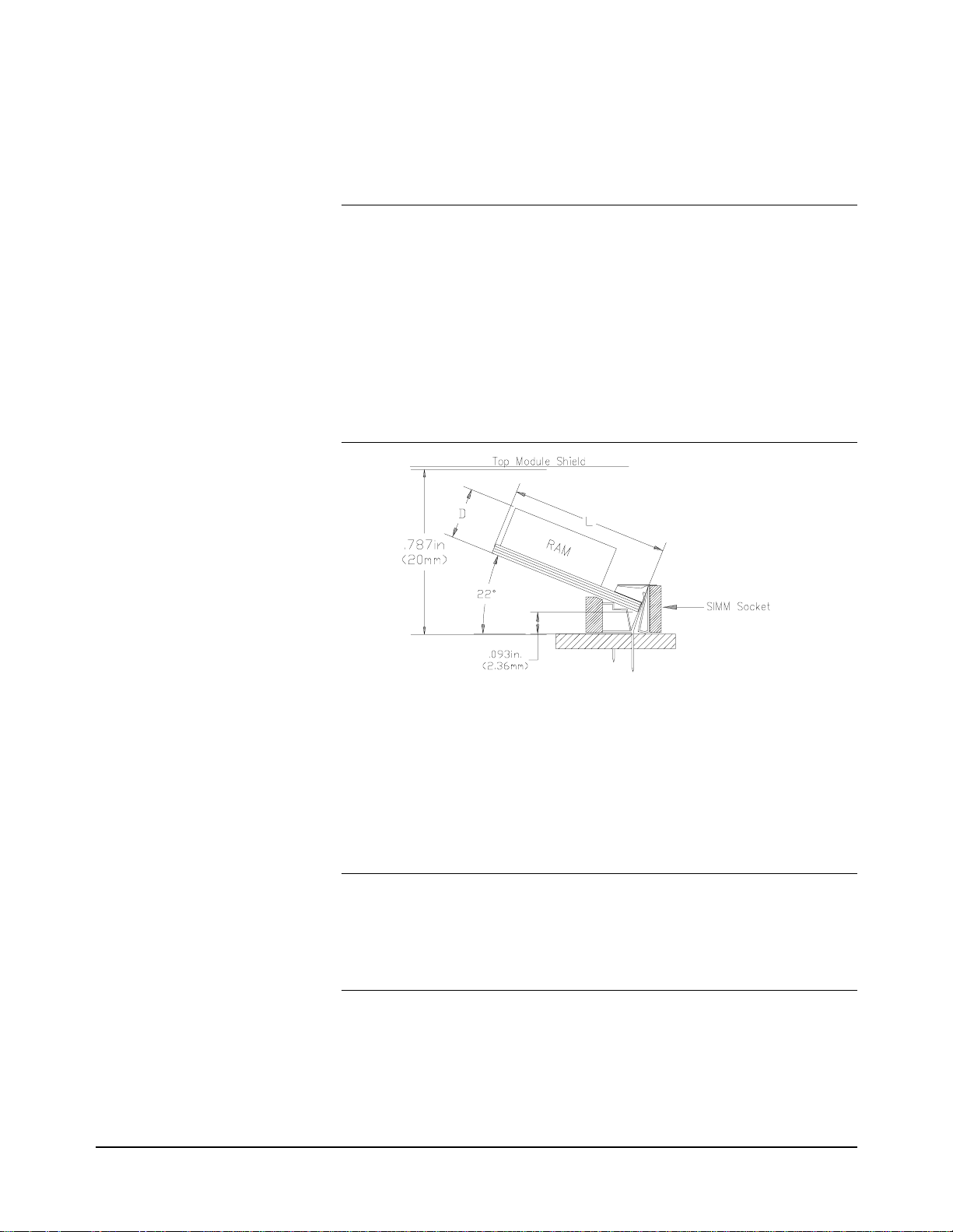
Note Although most commercially available PC SIMM RAM will work with
You can increase the size of RAM on your Digitize r mod ule by purchasing
PC SIMM memory and installing it on the module after you remove the
standard 4 Mbyte SIMM shipped with your digiti zer. Bot h FPM (Fast Page
Mode) and EDO (Extended Data Out) are supported.
your Digitizer, there are some that are physically too large and will make
contact with the top shield when installed. A standard 72 SIMM specifies
the length (L) or keying but does not spec if y the dept h (D). Cert ai n dept hs
are too large and not compatible. The E1563/E1564 has about 17.6 mm of
space from the bottom of the SIMM RAM inserted in the socket to the top
module shield (see diagram below). You must verify that the SIMM RAM
you purchase for replacement on the module has a depth (D) that will clear
the top module shield. You can use the 4 Mbyte SIMM RAM you remove
as a guide, as well as the dimensions in the diagram be low, when
purchasing your upgrade RAM .
RAM Install Procedure 1. Disconnect any field wiring from the module and remove power
from the mainframe before proceeding.
2. Remove the module from the mainframe and remove the top
shield from the module.
3. Remove the 4 Mbyte SIMM from t he PC boar d by f irst spr eadin g
the tabs at the ends of the SIMM connector. Store this SIMM in
an anti-static bag and save this part.
Note It is important that you retain the 4 Mbyte SIMM you remove from the
Digitizer. If you return your Digitizer to Hewlett-Packard for repair or
exchange, you must return it in the same configuration as it was shipped to
you. You must remove your large memory SIMM and replace it with the
standard 4 Mbyte SIMM shipped with the product.
4. Add your replacement SIMM to the module’s RAM socket.
5. Reinstall the module’s top shield.
6. Note the new memory configuration by checking the appropriate
12 Digitizer Module Set-up
Page 13

box on the module’s top shield.
7. Set both the “CALIBRATION CONSTANTS” switch and the
“FLASH” switch to the “Write Enable” position.
8. Install the module in your mainframe and apply power.
9. Set the new RAM memory size by sending the command:
DIAGnostic:MEMory:SIZE <
10. Query the memory size to verify the setting by sending:
DIAGnostic:MEMory:SIZE?
11. Remove mainframe power, remove the module and set the
“CALIBRATION CONSTANTS” and “FLASH” switches back
to the “Read Only” position.
12. Reinstall your module in your mainframe.
size
>
WARNING Tighten the faceplate mounting screws to prevent electric
shock in the case of equipment or field wiring failure.
Digitizer Module Set-up 13
Page 14
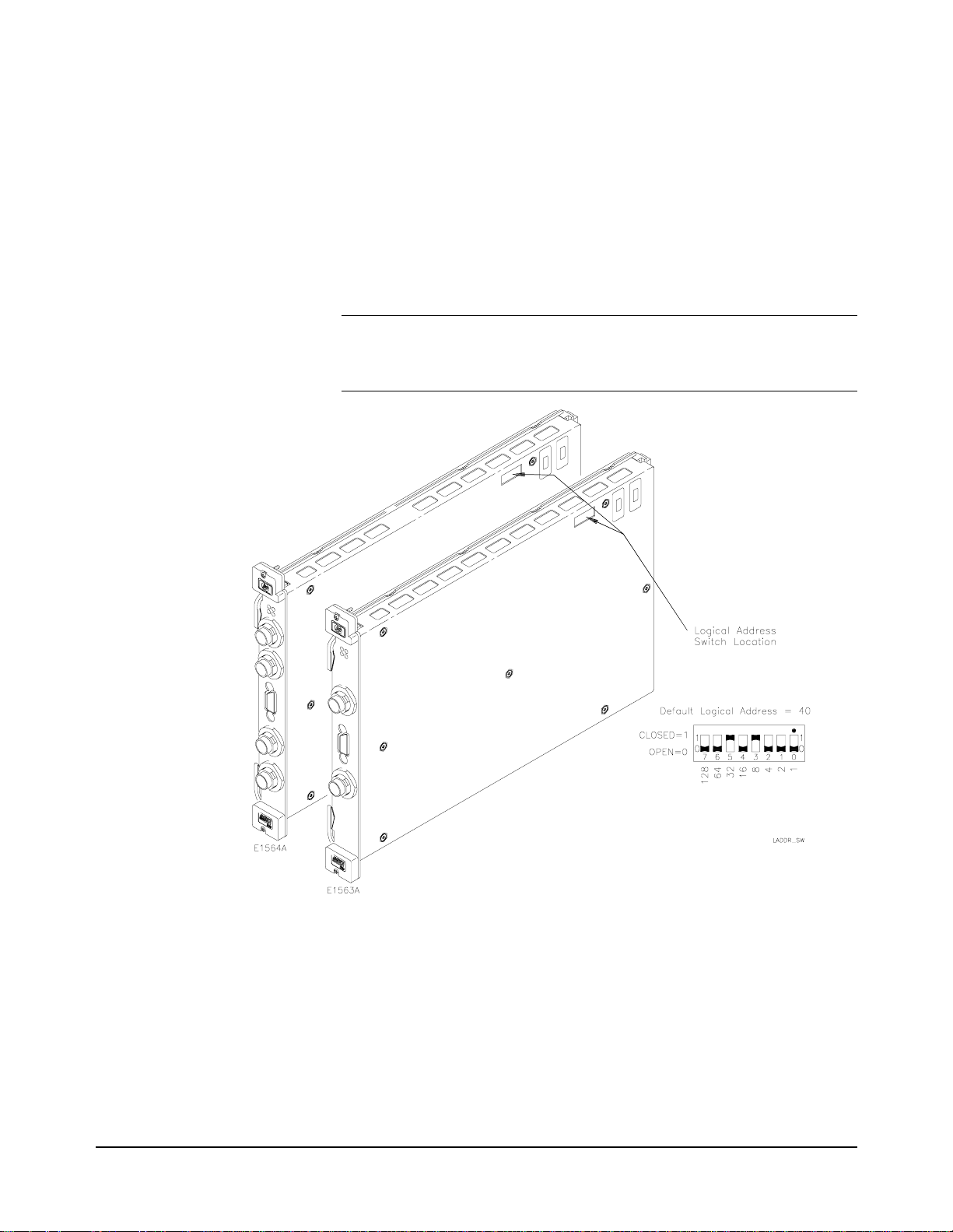
Setting the Module
Address Switch
Note When using an HP E1405A/B or E1406A as th e VXIb us r es ourc e man ager
The logical address switc h factory setting i s 40. Valid address are fro m 1 to
254 for static configuration (the address you set on the switch) and address
255 for dynamic configuration. The HP E1563A and HP E1564A do not
support dynamic configuration of the address.
If you install more than one digitizer, each module must have a different
logical address. If you use a VXIbu s command module, the l ogical addr ess
must be a multiple of eight (e.g., 32, 40, 48, 56, etc.). Each instrument must
have a unique secondary address which is the logical address divided by
eight. The Digitizer is shipped from the factory with logical address 40.
with SCPI commands, the digitizer’s address switch value must be a
multiple of 8.
Interrupt Line The HP E1563A and E1564A Digitizers are VXIbus interrupter s. You can
14 Digitizer Module Set-up
specify which interrupt line (1 through 7) the interrupt is transmitted. The
interrupt line is specified using the DIAGnost ic:INTerrupt:LINE comman d.
You can query the active interrupt line using the DIAGnostic:INTerrupt
:LINE? command. The default is no interrupt line enabled at power-up.
You specify “0” if y ou do not wa nt an inte rrupt . Res etting the module does
change the interrupt line setting and you must reset your interrupt setting.
Page 15
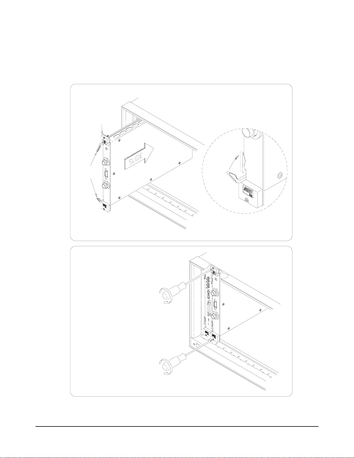
Installing the Digitizer in a Mainframe
The HP E1563A or E1564A can be installed in any slot (except slot 0) in a
C-size VXIbus mainframe. Refer to following diagram for the procedure to
install the Digitizer in a mainframe.
1. Set the extraction levers out.
2. Slide the HP E1563/E1564 into any
slot (except slot 0) until the backplane
connectors touch.
Extraction
Levers
4. Tighten the top and bottom
screws to secure the digitizer
module to the mainframe.
NOTE: The extraction levers will not seat
the backplane connectors on older VXIbus
mainframes. You must manually seat the
connectors by pushing in the module until
the module’s front panel is flush with the
front of the mainframe. The extraction levers may be used t o guide or remove the
digitizer.
Reverse the procedure to remove
the digitizer from the mainframe.
3. Seat the digitizer into the
mainframe by pushing in the
extraction levers.
Digitizer Module Set-up 15
Page 16
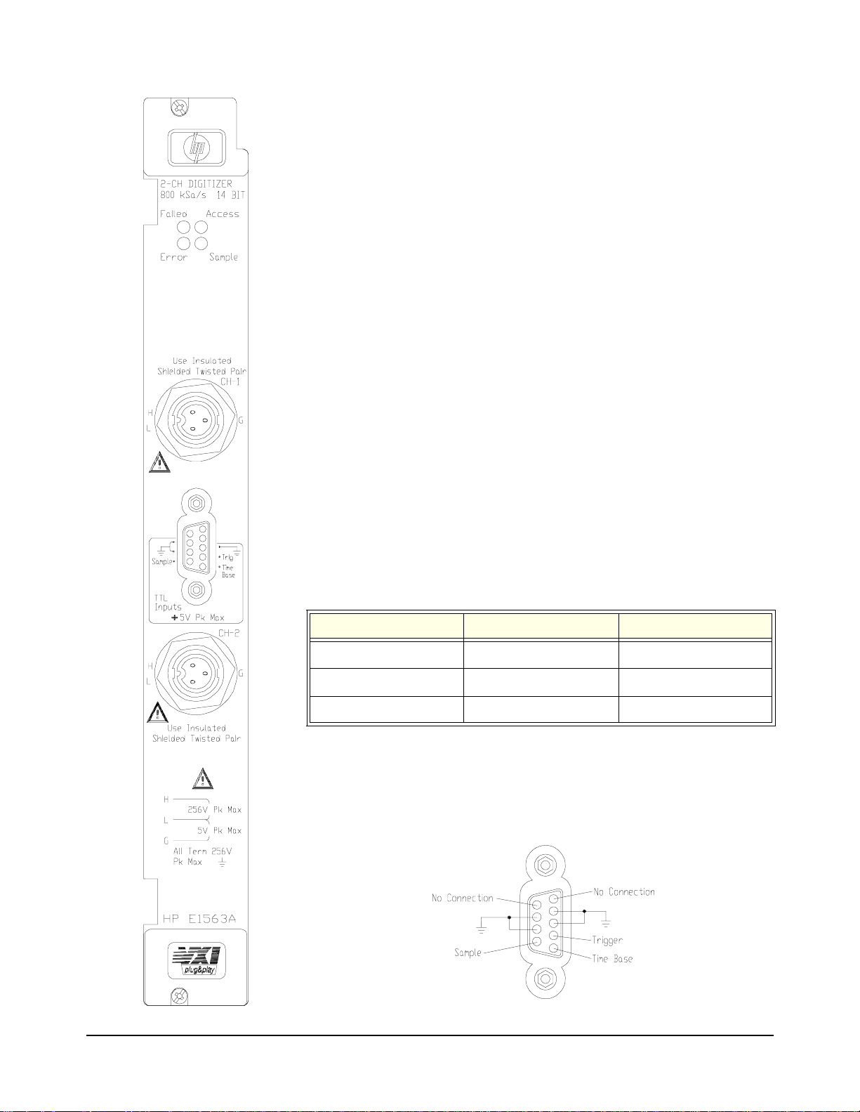
HP E1563A Front Panel Indicators
The “Failed” LED illuminates momentarily dur ing the digitizer’s
power-on boot.
The “Access” LED illuminates only when the backplane is
communicating with the digitizer.
The “Errors” LED illuminates only when an error is present in the
digitizer’s driver error queue. The error can result from improperly
executing a command or the digitizer being unable to pass self -test
or calibration. Use the SYST:ERR? comma nd repeatedly to read and
clear the error queue (or use *CLS to clear the error queue without
reading errors). A response of +0,”No error” indicates the error
queue is empty. See Appendix B, HP E15 63A and E1564A Digi tizer
Error Messages, for a list of all errors.
The “Sample” LED illuminates while t he digitizer samples the input for
a measurement. The “Sample” indicator typically will blink for slow
sample rates and is on steady-state for high sample rates .
HP E1563A Input Terminals
The HP E1563A Digitizer’s front panel contains two Switchcraft®
EN3™ Mini Weathertight Connectors (female) . Mating Switc hcraft®
Cord Connectors (male) are supplied with the module and the user
must provide the cable and ass emble the connector to the cable end.
Shielded twisted pair cab le is recommended with some reco mmendations shown in the following table that have an outside dimension
compatible with the cord connector.
Wire gauge Belden® cable P/N Alpha® cable P/N
20 AWG (7x28) 8762 none 22 AWG (7x30) 9462 5481C 24 AWG (7x32) 8641 5491C
HP E1563A D-subminiature Connector Pins
The front panel contains a 9-pin D-subminiature connector with the
following pin-out and associat ed SCPI commands (do not make any
connections to the top two pins):
SAMPle:SOURce EXT
TRIGger:SOURce EXT
ROSCillator:SOURce EXT
16 Digitizer Module Set-up
Page 17
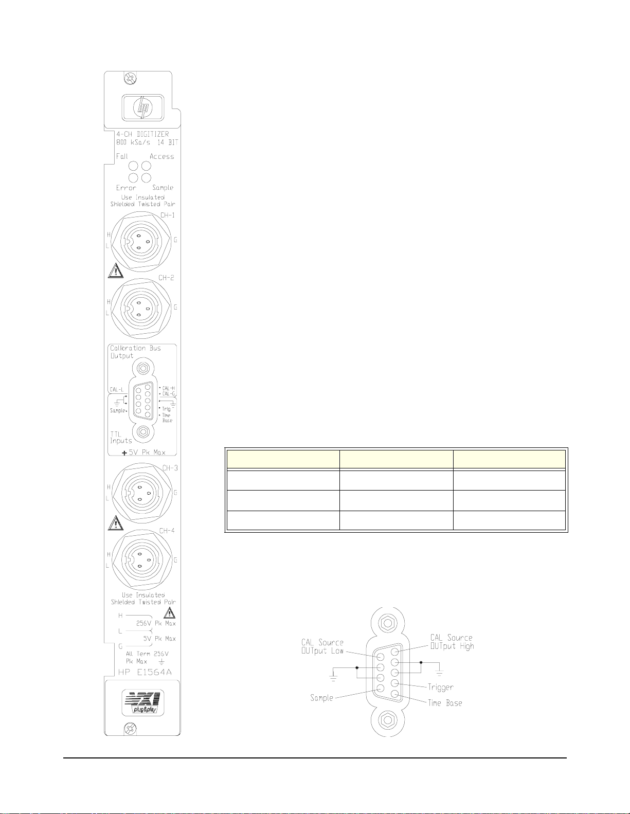
HP E1564A Front Panel Indicators
The “Failed” LED illuminates momentarily dur ing the digitizer’s
power-on boot.
The “Access” LED illuminates only when the backplane is
communicating with the digitizer.
The “Errors” LED illuminates only when an error is present in the
digitizer’s driver error queue. The error can result from improperly
executing a command or the digitizer being unable to pass self -test
or calibration. Use the SYST:ERR? comma nd repeatedly to read and
clear the error queue (or use *CLS to clear the error queue without
reading errors). A response of +0,”No error” indicates the error
queue is empty. See Appendix B, HP E15 63A and E1564A Digi tizer
Error Messages, for a list of all errors.
The “Sample” LED illuminates while t he digitizer samples the input for
a measurement. The “Sample” indicator typically will blink for slow
sample rates and is on steady-state for high sample rates .
HP E1564A Input Terminals
The HP E1564A Digitizer’s front panel contains four Switchcraft®
EN3™ Mini Weathertight Connectors (female) . Mating Switc hcraft®
Cord Connectors (male) are supplied with the module and the user
must provide the cable and ass emble the connector to the cable end.
Shielded twisted pair cable is recommended with some
recommendations shown in the following table that have an outside
dimension compatible with the cord connector.
Wire gauge Belden® cable P/N Alpha® cable P/N
20 AWG (7x28) 8762 none 22 AWG (7x30) 9462 5481C 24 AWG (7x32) 8641 5491C
HP E1564A D-subminiature Connector Pins
The front panel contains a 9-pin D-subminiature connector with the
following pin-out and associated SCPI commands:
CAL:SOURce INT
SAMPle:SOURce EXT
CAL:SOURce INT
TRIGger:SOURce EXT
ROSCillator:SOURce EXT
Digitizer Module Set-up 17
Page 18
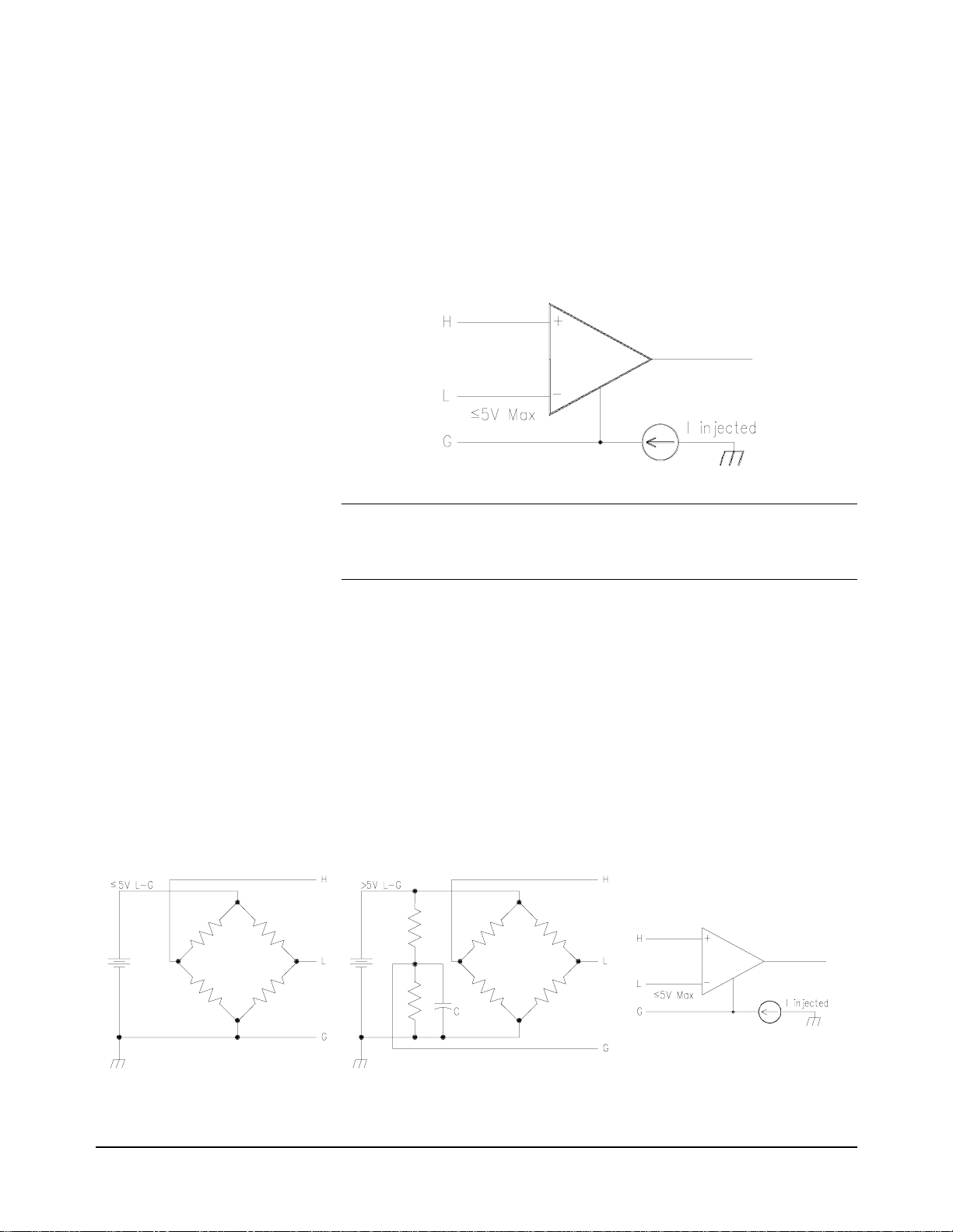
3-Wire and 2-Wire
Input Cabling
Considerations
The HP E1563A and E1564A Digitizers provide a three-terminal input
system (High, Low and Gu ard). An unavoidab le and u ndesirable current i s
injected from chassi s grou nd to t he Guard term inal. Dependen t on whet her
you measure on a low-voltage range or a high-voltage range, the way you
connect the Guard terminal may or may not i ntr oduce a measurement error
due to this current. This section describes some considerations you must
take to use the Guard terminal properly to minimize measurement error.
Digitizer Input Model The input model for the digitizer is shown below. Maximum voltage
between Low and Guard is 5V.
Note Maximum voltage between Low and Guard is 5V. Exceeding this
limitation will not damage your digitizer but will generate invalid data for
any measurement taken.
Three-Wire Connection This section shows two examples of connecting the i nput using a three-wi re
connection. Both example s can be const ructed using shi elded twis ted pair.
The first example shows making connections for a bridge measurement
where the L-to-G voltage is ≤ 5V and where the L-to-G voltage ex ceeds 5V.
A “Wagner ground” is used to satisfy the L-to-G restriction of ≤ 5V and to
make a Guard connec tion point that min imizes measuremen t error due to th e
digitizer’s injected current. A capacitor is added to the Wagner ground to
provide a signal path to ground to minimize common mode voltages. The
second example shows measuri ng the voltage across a smal l current sensing
resistor where the input to the digitizer is switched through a multiplexer
switch module.
3-Wire Cable Connection Example 1
18 Digitizer Module Set-up
Page 19
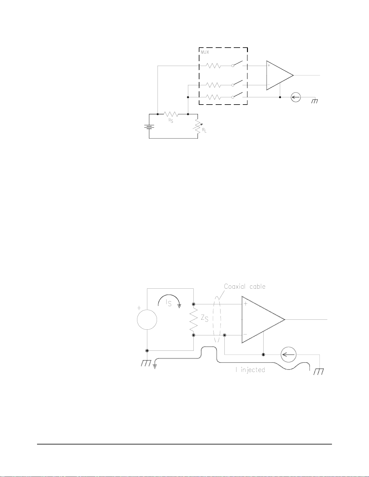
3-Wire Cable Connection Example 2
Two-Wire Connection When Low and Guard are simply connected together at the di gitizer ’s input
on a low-voltage range (4V and below), the injected current is directed to
flow through the source impedance (in a floating source) and the resultant
voltage drop will introduce a me asurement error . The result ant voltage d rop
through the source impedance can be a significant error on low-voltage
ranges where the volt ag e of inter est is small . It is n ot as s ignif icant a n err or
on high-voltage ranges simply because the error introduced is not a
significant part of a larger voltage; the percent of error is less signifi cant.
Measurement error can increase significantly when you connect Low to
Guard at the digitizer’s input AND use switches to switch input signals to
the digitizer. Some switches hav e input prote ction resist ors (usuall y 100Ω)
in series with the switch. The digitizer’s injected current now generates a
voltage drop across this resistor in addition to the voltage drop generated
across the source impedan ce. Even with a grounded source, an error volt age
is generated across the switches current limiting resistor .
2-Wire Cable Connection Example
Digitizer Module Set-up 19
Page 20

Cable Connector Assembly Instructions
Step 1. Strip cable as shown and feed the end of the cable throu gh the boot, cabl e clamp housing , and coupling
ring in the order and position shown. NOTE: The coupling ring can also be inserted onto the cable connector
from the front.
Step 2. Orient the HI, LO and Guard conductors with the corresponding pins.
Step 3. Solder conductors to pins. CAUTION - Excessive heat on the connector terminals can cause
damage to the connector.
20 Digitizer Module Set-up
Page 21

Step 4. Assemble the connector.
C
A. Align coupling ring’s tabs with cable connector’s side notches and push the coupling ring onto the cable
connector.
B. Push the cable clamp housing forward until it locks into the connector body and snap the two clamps into
their compartments to secure the cable.
C. Push the boot all the way forward to seat tightly onto the cable clamp housing.
A
B
Cable
Connector
oupling
Ring
Cable Clamp
Housing
Boot
C
To mate the cable connector to the instrument’s front panel connector...
1. Hold the cable connector by the rubber boot a nd align the no tched key slot with the key on t he left si de of the
instrument’s front pa nel conne ctor. Inse rt the c able con nector just en ough to enc ounter inserti on resi stance and
stay in plac e.
2. Grasp the coupling ring and slowl y rotate it clockwise, while you gently push the connector to ward the panel
mount, until the notches on the coupling ring drop into the front panel connector detents.
3. Continue rotating unti l y ou feel the coupling ring ride over the locking “bump” which secures t he c onnector
to the instrument’s front panel connector.
Digitizer Module Set-up 21
Page 22

Initial Operation To program the Digitizer using SCPI, you must select t he i nterface address
and SCPI commands to be used. General information about using SCPI
commands is presented at the beginning of Chapter 3. See the HP 75000
Series C Installation and Getting Started Guide for interface addressing.
Note This discussion applies only to SCPI (Standard Commands for
Programmable Instruments) programming. The program is written using
VISA (Virtual Instrument S oftware Architecture) function calls. VISA
allows you to execute on VXI Plug&Play s ystem fr ameworks t hat ha ve the
VISA I/O laye r installed (visa.h “in clude” file).
Programming the
Digitizer
Example: Query the Digitizer for its ID and for system errors.
Programming the digitizer using Standard Commands for Programmable
Instruments (SCPI) requir es tha t you selec t the contr oller lang uage (e .g., C,
C++, Basic, Visual Basi c, etc.), i nterface a ddress and SCPI commands to be
used. See the “C-Size Installation and Getting Started Guide” (or
equivalent) for interfacing, addressing and controller information.
The following C program verifies communication between the controller,
mainframe and digitizer. It resets the module (*RST), queries the identity
of the module (*IDN?) and queries the module for system errors.
#include <stdio.h>
#include <visa.h>
/*** FUNCTION PROTOTYPE ***/
void err_handler (ViSession vi, ViStatus x);
void main(void)
{
char buf[512] = {0};
#if defined(_BORLANDC_) && !defined(_WIN32_)
_InitEasyWin();
#endif
22 Digitizer Module Set-up
ViStatus err;
ViSession defaultRM;
ViSession digitizer;
/* Open resource manager and digitizer sessions */
viOpenDefaultRM (&defaultRM);
viOpen(defaultRM, “
/* Set the timeout value to 10 seconds. */
viSetAttribute (digitizer, VI_ATTR_TMO_VALUE, 10000);
/* Reset the module. */
err = viPrintf(digitizer, “*RST\n”);
if (err<VI_SUCCESS) err_handler (digitizer, err);
GPIB-VXI0::9::40”,VI_NULL,VI_NULL, &digitizer);
Page 23

/* Query for the module’s identification string. */
err = viPrintf(digitizer, “*IDN?\n”);
if (err<VI_SUCCESS) err_handler (digitizer, err);
err = viScanf(digitizer, “%t”, buf);
if (err<VI_SUCCESS) err_handler (digitizer, err);
printf (“Module ID = %s\n\n”, bu f);
/* Check the module for system errors. */
err = viPrintf(digitizer, “*SYST:ERR?\n”);
if (err<VI_SUCCESS) err_handler (digitizer, err);
err = viScanf(digitizer, “%t”, buf);
if (err<VI_SUCCESS) err_handler (digitizer, err);
printf (“System error response = %s \n\n”, buf);
viClose (digitizer); /* close the digitizer session */
} /* end of main */
/*** Error handling function ***/
void err_handler (ViSession digiti zer, ViStatus err)
{
char buf[1024] = {0};
viStatusDesc (digitizer, err, buf); /* retrieve error description */
printf (“ERROR = %s\n”, buf);
return;
}
Digitizer Module Set-up 23
Page 24

24 Digitizer Module Set-up
Page 25
Digitizer Application Information
Using this Chapter
This chapter provides digitizer application information in four parts.
•Digitizer Block Diagrams.
•Triggering the Digitizer.
•Master-Slave Operation.
•HP E1563A and E1564A Digitizer Application Examples.
Digitizer Block Diagrams
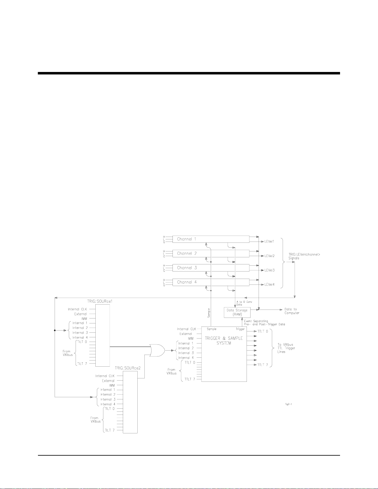
A block diagram of the HP E1564A 4-Channel Di gitizer is shown in Figure
2-1. The HP E1563A 2-Channel Digitizer has the same internal structure
without channels 3 and 4. Note the TRIG:LEVel< channel> signals drive the
internal trigger inputs, LEVel1 drives INT1, LEVel2 drives INT2, etc.
Chapter 2
Figure 2-1. Digitizer Block Diagram.
Digitizer Application Information 25
Page 26

Channel Block
Diagram
Figure 2-2 is a block diagram of an individual channel and the
interconnections between channels. Note that the sample signal goes to all
channels. The stai r-stepp ed commands b eneath t he dia gram show the SCPI
commands that are u sed t o pr ogr am e ach section of a channe l. In this case,
all the commands ar e written for c hannel 4. See Chapter 3, SCPI Co mmand
Reference, for a full description of the commands illustrated here.
RANGE SELECTION:
INPut4:STATe ON | 1 | OFF | 0
VOLTage4:DC:RANGe <range>
FILTER SETTING:
INPut4:FILTer:LPASs:FREQ <freq>
INPut4:FILTer:LPASs:STATe ON | 1 | OFF | 0
Figure 2-2. Digitizer Channel Block Diagram.
QUERY LAST READING (current value):
SENSe:DATA:CVTable? (@4)
LIMIT and LEVEL COMPARISON:
CALCulate4:LIMit:LOWer:DATA <value>
CALCulate4:LIMit:LOWer:STATe ON | 1 | OFF | 0
or
CALCulate4:LIMit:UPPer:DATA <value>
CALCulate4:LIMit:UPPer:STATe ON | 1 | OFF | 0
or
TRIGger:SOURce INTernal4
TRIGger:LEVel4 <voltage>
TRIGger:SLOPe4 POS | 1 | NEG | 0
26 Digitizer Application Information
Page 27
Pre-Trigger/
Post-Trigger Block
Diagram
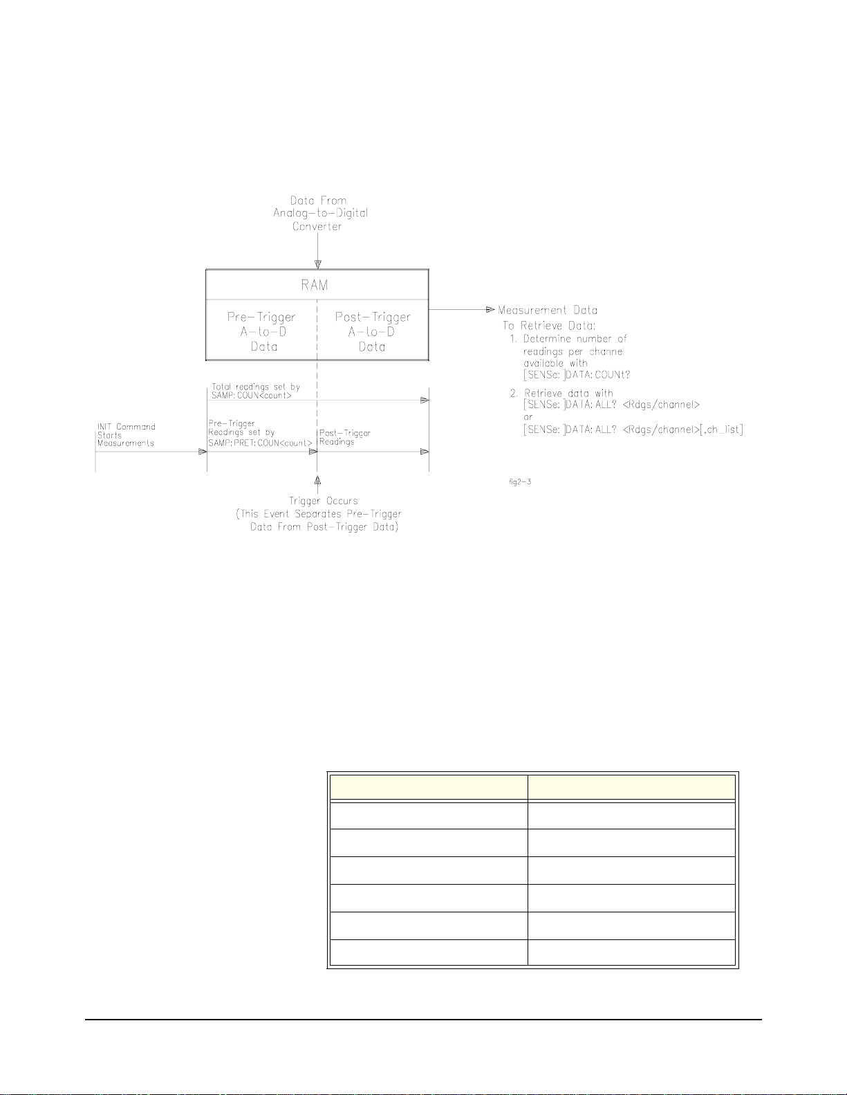
Figure 2-3 illustrates relationship of pre-trigger readings and post-trigger
readings with the trigger event. See Chapter 3, SCPI Command Reference,
for a full description of the commands illustrated here.
Figure 2-3. Pre-Trigger and Post-Trigger Block Diagram.
Power-on and Reset State
Table 2-1 describes all power -on and r eset sta tes for the digi tizer. The reset
state obtained after executing a *RST command is the same as the power-on
state.
DIAG:INTerrupt:LINE interrupt line #1
FORMat:DATA ASCii
INPut1:FILTer:FREQ 0 (no filter on channel 1 )
INPut2:FILTer:FREQ 0 (no filter on channel 2 )
INPut3:FILTer:FREQ 0 (no filter on channel 3 )
INPut4:FILT:FREQ 0 (no filter on channel 4 )
Table 2-1. Power- on and Reset States.
Parameter Power-on/Reset State
Digitizer Application Information 27
Page 28

Table 2-1. Power- on and Reset States.
Parameter Power-on/Reset State
INPut1:STAT e ON (channel 1 input state)
INPut2:STAT e ON (channel 2 input state)
INPut3:STAT e ON (channel 3 input state)
INPut4:STAT e ON (channel 4 input state)
OUTPut:TTLT0-7:SOURce TRIGger (all TTLTrigger lines)
OUTPut:TTLT0-7:STATe OFF (all TTLTrigger lines)
ROSCillator:SOURce INTernal
SWEep:POINts 1 (one sample)
SWEep:OFFSet:POINts 0 (no pretrigger samples)
VOLT1:RANGe 256V (channel 1 range)
VOLT2:RANGe 256V (channel 2 range)
VOLT3:RANGe 256V (channel 3 range)
VOLT4:RANGe 256V (channel 4 range)
VOLT1:RESolution 7.8125 mV (channel 1 res)
VOLT2:RESolution 7.8125 mV (channel 2 res)
VOLT3:RESolution 7.8125 mV (channel 3 res)
VOLT4:RESolution 7.8125 mV (channel 4 res)
SAMPle:COUNt 1 (one sample)
SAMPle:PRETrigger:COUNt 0 (no pretrigger samples)
SAMPle:SLOPe POSitive
SAMPle:SOURce TIMer (internal time base)
SAMPle:TIMer 1.3 µS
TRIGger:LEVel1 -256V (channel 1 level)
TRIGger:LEVel2 -256V (channel 2 level)
TRIGger:LEVel3 -256V (channel 3 level)
TRIGger:LEVel4 -256V (channel 4 level)
TRIGger:SOURce1 IMMediate (source 1 not ch 1)
TRIGger:SOURce2 HOLD (source 2 not ch 2)
28 Digitizer Application Information
TRIGger:SLOPe1 POSitive (slope 1 not ch 1)
TRIGger:SLOPe2 POSitive (slope 2 not ch 2)
Page 29

Triggering the Digitizer
Two Common
Trigger Sources per
Channel
Triggering digiti zer readi ngs acro ss all inpu t chan nels is acc omplished with
one or both of the two available trigger sources (TRIGger:SOURce1 and
TRIGger:SOURce2). The trigger event can be different for each source e.g.,
SOURce1 can be EXT and SOURce2 can be TTLT0. You use the
TRIG:SOURce<n> command to set the trigger source event options which
can be OFF | BUS | EXT | HOLD | IMMEDIATE | INTernal1-4 | TTLT0-7.
You must execute the TRIG:SOURce<n> command two times to set both
trigger sources (TRIG:SOUR1 and TRIG:SOUR2). At power-up and after
resetting the module with *RST, TRIG:SOUR1 defaults to IMM and
TRIG:SOUR2 defaults to HOLD. The number of readings set by the
SAMPle:COUNt command are taken after the trigger event occurs.
Note Do not confuse TRIG:SOUR1 as being associated with only channel 1 (as
well as TRIG:SOUR2 with only channel 2). Both sources are common to
ALL channels and the “1” and “2” are not chann el designator s but “sourc e”
designators.
Internal Triggers Using SCPI or Plug&Play, you can trigger internally off of a voltage level
from any channel. Trigger level is set using the
<
voltage
trigger event. You then set the trigge r source to trigg er in terna lly fro m that
channel using the
example, if you want to trigger from a 11.5V level on channel 2, you send
the following commands:
TRIG:SOUR INT2.
to the interna l trigger source.
> command for the particular channel you want to generate the
TRIG:SOURce<n> INT<channel> command. For
VOLT2:RANG 16; TRIG:LEV2 11.5;
Figure 2-1 illustrates the relationship of the trigger level
TRIG:LEVel<channel>
Internal Trigger Level
Detection
Each channel has a level compare circuit that compares the input signal to
the value se t by the TRIG:LEVel<channel> command. This level initiates
a trigger when the input signal equals OR EXCEEDS the value set by the
TRIG:LEVel command. This means the trigger can occur at a value other
than the value set by the TRIG:LEVel command. For example, assume a
trigger level of 0V on a ramp from -1V to +1V. The first samples may be
negative values close to ze ro. These values will not cause a trig ger because
they do not equal o r exceed the t rigger level value yet. Th e next sample may
be a positive value gr eater than the trig ger level. The trig ger compare circuit
(see Figure 2-2) det ects this level is equ al to or grea ter tha n the trigg er level
value set and a trigger is generated. It was not however, generated at the
exact trigger level value set by the TRIG:LEVel command.
Digitizer Application Information 29
Page 30

External Trigger You can provide an external trigger common to all channels. The external
trigger connection is on the digit izer’s front panel D-subminiature con nector
“Trig” pin. You set th is input as the trig ger source f or all c hannels using the
TRIGger:SOURce<n> EXT command. You use the TRIGger:SLOPe<n>
POSitive | NEGative
command to set which signal edge will trigger.
Master-Slave
Operation
The HP E1563A and HP E1564A Digitizers can be configured in a
master-slave configurat ion. This configur ation allows a master modul e and
one or more slave modules to have their measurements synchronized.
Synchronization occ urs by having all channels trigger off of the s ame trigger
event as well as all channels sampling from one sample signal.
•The sample synchronization signal is always generated by the master.
•The TTL trigger event can be generat ed by either the maste r modul e or
any of the slave modules. This allows a slave module (as well as the
master module) to use one of the four internal trigger sources or their
external trigger source to trigger a measurement.
Both the trigger signal and the sample signal are put on the VXI backplane
TTL trigger (TTLT) lines where the master module and all slave modules
receive the signals simultaneously. TTL trigger lines are used in pairs
between the master and slave(s) where one TTL trigger line carries the
sample signal and the other carries the trigger signal. The next section
describes how these TTL trigger lines are paired.
Trigger Mode The TRIGger:MODE command is used to configure Digitizers for master-
slave operation. The mode can be NORMal, MASTer or SLAVe.
NORMal Mode The default setting for trigger mode is TRIGger:MODE NORMa l which
configures the module as an individual instrument.
MASTer Mode Use the TRIGger:MODE MASTer<n> command to configure a module as
a master. The eight TTL trigger lines (TTLT0-TTLT7) on the VXI
backplane allow four different pairings as shown in Table 2-1 (MASTer0SLAVe0, MASTer2-SLAVe2, MASTer4-SLAVe4 and MASTer6SLAVe6). You must select an unused set of TTL trigger lines for the
master-slave coupling when det ermining which ma ster mode to set. Do not
use a TTLT line already used by
30 Digitizer Application Information
SAMPle:SOURce or TRIGger:SOURce.
Page 31

SLAVe Mode Use TRIGger:MODE SLAVe0 to configure a module as a slave to a
MASTer0 module. MASTer0 and SLAVe0 modules share TTL tr igger lines
TTLT0 and TTLT1. TTLT0 carries the sample signal and TTLT1 carries
the trigger signal. The following table shows all pairs of TTL trigger lines
for each master-slave mode.
Table 2-2. Trigger Sources for Master-Slave Modes.
MASTer-SLAVe
Trigger Sources
MASTer
MODE
MASTer 0 SLAVe0 TTLT1 Any source
MASTer 2 SLAVe2 TTLT3 Any source
MASTer 4 SLAVe4 TTLT5 Any source
MASTer 6 SLAVe6 TTLT7 Any source
SLAVe
MODE
TRIG:SOUR1 TRIG:SOUR2
(except TTLT0 & TTLT1)
(except TTLT2 & TTLT3)
(except TTLT4 & TTLT5)
(except TTLT6 & TTLT7)
Master-Slave Diagra ms Figures 2-4 illustrates a module confi gured a s a master module. Figu re 2-5
illustrates a module configured as a slave module.
Digitizer Application Information 31
Page 32

TRIG:MODE MASTer0 pairs TTLT0 (sample) with TTLT1 (trigger )
The MASTer0 module will function with all SLAVe0 modules.
1) The trigger source from the master can be
set with
| TTLT<n>
2)
lines as if OUTPut:TTLT0:SOURce SAMPle
TRIG:SOURce1,2 IMM | INT1-4 | EXT
.
TRIG:MODE MASTer0 drives the TTL
and OUTPut:TTLT1:SOURce TRIGger have
been set
.
3) The master module generates the sample
signal that all modules (master and slaves)
initiate a measurement from.
Figure 2-4. Master Module Configuration Block Diagram.
MODE MASTer Sample Signal
MASTer0 TTLT2-7 | INT1-4 | EXT MASTer2 TTLT0,1,4-7 | INT1-4 | EXT MASTer4 TTLT0-3,6-7 | INT1-4 | EXT MASTer6 TTLT0-5 | INT1-4 | EXT
4) MASTer0 sets the TTLT1 line as if it were
TRIG:SOUR1 TTLT1. However, the query
TRIG:SOUR? will not return this setting. This
line is simply dedicated for synchronization
between the two modules in the master- slave
mode. You should not use this line for any
other purpose with the OUTPut, SAMPle or
TRIGger commands.
32 Digitizer Application Information
Page 33

TRIG:MODE SLAVe0 pairs TTLT0 (sample) with TTLT1 (trigger)
A SLAVe0 module will function with other SLAVe0 modules and
the MASTer0 module.
1) The trigger source from the slave can be set
with
TRIG:SOURce2 IMM | INT1-4 | EXT |
TTLT<n>
.
SLAVe
MODE
SLAVe0 TTLT0
SLAVe2 TTLT2
SLAVe4 TTLT4
SLAVe6 TTLT6
Sample signal
Figure 2-5. Slave Module Configuration Block Diagram.
2) SLAVe0 sets the TTLT0 line as if it were
SAMP:SOUR TTLT0 and sets the TTLT1 line as
if it were
queries
TRIG:SOUR1 TTLT1. However, the
SAMP:SOUR? or TRIG:SOUR? will not
return these settings. These lines are simply
dedicated for synchronization between the
modules in the master- slave mode. You s hould
not use these lines fo r any other purpose with the
OUTPut, SAMPle or TRIGger commands.
Digitizer Application Information 33
Page 34

Input Overload Condition
Overload voltages may occur which will open the channel input relay
disconnecting the inpu t signal from th e channel. Overlo ad voltage by rang e
is shown in the following table.
Range Voltage Input Condition Vmax
62 mV to 4V High or Low to Guard >20V 16V to 256V Low to Guard >40V
Overload Reporting The overload is reported both when the readings are retrieved and when the
next measurement is initiated. If an overload occurred:
1. An error message is returned when data is retrieved informing you
that the data is questionable
2. An error message is also returned when you initiate the next
measurement
(Overload detected - attempting re-connect of input relays).
(Overload detected - data questionable).
34 Digitizer Application Information
Page 35

HP E1563A and E1564A Digitizer Application Examples
This section contains example programs that demonstrate several
applications of the HP E1563A or HP E1564A Digitizer. The examples
described in this section list only the SCPI commands (see Chapter 3, HP
E1563A and HP E1564A Command Reference) required to perform the
application. The programming language is not included in print but C
programs are included on the VXIplug&play driver media under the
subdirectory "examples ". You can use these examples to help you learn the
capabilities of the HP E1563A/E1564A and then to help you develop
programs for your specific application
C Language
Example Progra m s
C Programs All projects written in C programming language require the following
Hardware Used 486 IBM compatibl e computer running Windows 3.1. The computer h as an
Example programs are provided on the VXIplug&play media. These
programs have been compiled and tested using Microsoft® Visual C++™
Version 1.51 for the C progr ams. All of t he C Language example pro grams
in this section are writ ten for the HP 82341A HP-IB Interface Card using the
HP VISA I/O Library.
Microsoft® Visual C++™ Version 1.51 settings to work properly:
Project Type:QuickWin application (.EXE)
Project Files:<source code file name>.C
[drive:]\VXIPNP\WIN\LIB\MSC\VISA.LIB (Microsoft® compiler)
[drive:]\VXIPNP\WIN\LIB\BC\VISA.LIB (Borland® compiler)
Memory Model:Options | Project | Compiler | Memory Model
Directory Paths:Options | Directories
Include File Paths: [drive:]\VXIPNP\WIN\INCLUDE
Library File Paths: [drive:]\VXIPNP\WIN\LIB\MSC (Microsoft®)
[drive:]\VXIPNP\WIN\LIB\BC (Borland®)
Example programs: located on the Universal Instrument Drivers CD
HP 82341 HP-IB interface and HP SICL/ W ind ows 3.1 & Windows/NT for
HP-IB software. The VXI modules we re loaded i n a VXI C-size mainframe
using an HP E1406A Command Module as reso urc e mana ger conn ect ed t o
the computer via the HP 82341 HP-IB card.
⇒ Large
Compiling and
Linking a C
Program
You can find specific instructions for compiling C language programs for
the PC in the HP VISA User’s Guide. See the section "Compiling and
Linking an HP VISA Program.
Digitizer Application Information 35
Page 36

Making Digitizer
Measurements
This section provides three programs that demonstra te how to make digitizer
measurements and retrieve data. SCPI command sequences for each
program are contained in the boxes. The three programs are:
1. Use an IMMediate trigger to begin the sampling measurements on
two channels and retrieve the interleaved readings from FIFO
memory.
2. Use the internal level trigger to trigger off of an input ramp signal as
it crosses zero. This program takes pre-trigger readings as well as
post trigger readings.
3. Use an external trigger input at the D-connector “Trig” input to
trigger rea dings.
READINGS.C Use an IMMediate trigger to begin the sampling measurements on two
channels and retrieve the interleaved readings from FIFO memory.
SCPI COMMANDS IN THIS PROGRAM:
*RST
*CLS
VOLT1:RANG 4
VOLT2:RANG 4
SAMP:COUN 20
SAMP:PRET:COUN 10
INIT
DATA? 20,(@1,2)
Enter statement
reset the digitizer
clear the status system
set ch 1 to 4V range
set ch 2 to 4V range
set sample count to 20
(common to all channels)
set pre-trigger count to 10
(common to all channels)
initiate measurements
read 20 readings from chs 1 & 2
enter readings into the computer
Separate the interleaved readings and display them.
Comments • Resetting the module sets the data format to ASCII, sample source to
timer and trigger source to immediate.
36 Digitizer Application Information
Page 37

RAMP.C Use the internal level trigger to trigger off of an input ramp signal as it
crosses zero. This pr ogram takes pr e-trigger rea dings as well as post tri gger
readings.
SCPI COMMANDS IN THIS PROGRAM:
*RST
*CLS
VOLT1:RANG 4
SAMP:COUN 7
SAMP:PRET:COUN 3
SAMP:TIM 50e-6
TRIG:SOUR INT1
TRIG:LEV1 0
TRIG:SLOP POS
INIT
DATA? 7,(@1)
Enter statement
Display the readings.
Comments • Resetting the module sets the data format to ASCii, sample source to
TIMer and trigger source to IMMediate. The sample interval and the
trigger source are changed from the reset setting.
reset the digitizer
clear the status system
set ch 1 to 4V range
set sample count to 7
(common to all channels)
set pre-trigger count to 3
(common to all channels)
set sample interval to 50 µS
set trigger source to a level on
channel 1
set the trigger level to 0V
set trigger slope to positive
initiate measurements
read 7 readings from ch 1
enter readings into the computer
•Resetting the module also sets the trigger level to 0V and the trigger
slope to positive. Trigger level and slope commands are resent to
reiterate the level and slope of the trigger. In this case, these
commands are redundant.
EXT_TRIG.C Use an external trigger input at the D-connector “Trig” input to trigger
readings.
SCPI COMMANDS IN THIS PROGRAM:
*RST
*CLS
VOLT1:RANG 4
SAMP:COUN 7
SAMP:PRET:COUN 3
SAMP:TIM 100e-6
TRIG:SOUR EXT
TRIG:LEV1 0.5
TRIG:SLOP POS
INIT
DATA? 7,(@1)
Enter statement
Display the readings.
reset the digitizer
clear the status system
set ch 1 to 4V range
set sample count to 7
(common to all channels)
set pre-trigger count to 3
(common to all channels)
set sample interval to 100 µS
set trigger source to EXTernal
(requires an external input to the
“Trig” pin on the front panel
D-connector)
set the trigger level to 0.5V
set trigger slope to positive
initiate measurements
read 7 readings from ch 1
enter readings into the computer
Digitizer Application Information 37
Page 38

Comments • Resetting the module sets the data format to ASCii, sample source to
TIMer and trigger source to IMMediate. The sample interval and the
trigger source are changed from the reset setting.
•Resetting the module also sets the trigger level to 0V and the trigger
slope to positive. Trigger level and slope commands are resent to
reiterate the level and slope of the trigger. In this case, the slope
command is redundant.
38 Digitizer Application Information
Page 39

Digitizer Command Reference
Using This Chapter
This chapter describes the Standard Commands for Programmable Instruments
(SCPI) and IEEE 488.2 Common (*) commands applicable to the HP E1563A and
HP E1564A Digitizers.
Chapter 3
Command
Types
Common
Command Format
SCPI
Command
Format
Commands are separated into two types: IEEE 488.2 Common Commands and SCPI
Commands.
The IEEE 488.2 standard defines the Common commands that perform functions
like reset, self-test, status byte query, etc. Common commands are four or five
characters in length, always begin with the asterisk character (*), and may include
one or more parameters. The command keyword is separated from the first
parameter by a space character. Some examples of common commands are shown
below:
*RST *ESR 32 *STB?
The SCPI commands perform functions such as making measurements, querying
instrument states, or retrieving data. The SCPI commands are grouped into
command "subsystem structur es". A command subsystem struct ure is a hierarchica l
structure that usually consists of a top level (or root) command, one or more
low-level commands, and their paramete rs. The following exampl e shows the root
command CALibration and its lower-level subsystem commands:
CALCulate
:LIMit:FAIL?
:LIMit:LOWer[:STATe] ON | 1 | OFF | 0
:LIMit:LOWer[:STATe]?
:LIMit:LOWer:DATA <
:LIMit:LOWer:DATA?
:LIMit:UPPer[:STATe] ON | 1 | OFF | 0
:LIMit:UPPer[:STATe]?
:LIMit:UPPer:DATA <
:LIMit:UPPer:DATA?
value>
value
>
Command
Separator
CALCulate is the root command, LIMit is a second level command, FAIL?, LOWer
and UPPer are third level commands and DATA, DATA?, STATe and STATe? are
fourth level commands.
A colon (:) always separates one command from the next lower level command as
shown below:
CALCulate:LIMit:FAIL?
Colons separate the root command from the second level command
Digitizer Command Reference 39
Page 40

(CALCulate: LIMit) and the second le vel from the third level (LIMit:FAIL?).
Abbreviated
Commands
Implied
Commands
The command syntax shows most commands as a mixture of upper and lower case
letters. The upper case letters indicate the abbreviated spelling for the command.
For shorter program lines, send the abbreviated form. For better program
readability, you may send the entir e command. The inst rument will accept either the
abbreviated form or the entire command.
For example, if the command syntax shows CALCulate, then CALC and
CALCULATE are both acceptable forms. Other forms of CALCulate, such as
CALCU or CALCUL will generate an error. Addi tionally, SCPI commands are case
insensitive. Theref ore, you may use upper or lower case letters and commands of the
form CALCULATE, calculate, and CaLcUlAtE are all acceptable.
Implied commands are those which appear in square brackets ([]) in the command
syntax. (Note that the brac kets are not part of the command; do not s end them to the
instrument.) Suppose you send a second level command but do not send the
preceding implied command . In th is case, t he instru ment assumes you inten d to use
the implied command and it responds as if you had sent it. Examine the partial
SENSe subsystem shown below:
[SENSe:]
range
VOLTage[:DC]:RANGe <
VOLTage[:DC]:RANGe? [MIN|MAX]
The root command SENSe is an implied command; so is the third level command
DC. For example, to se t the di gitizer ’s DC voltage range to MAX, you can send one
of the following three command statements:
>|MIN|MAX
SENS:VOLT:DC:RANG MAX
VOLT:DC:RANG M AX
VOLT:RANG MAX
40 Digitizer Command Reference
Page 41

Parameters Parameter Types. The following table contains explanations and examples of
parameter types you might see later in this chapter.
Table 3-1.
Parameter
Type
Numeric Accepts all commonly used decimal representations of number
including optional signs, decimal points, and scientific notation.
123, 123E2, -123, -1.23E2, .123, 1.23E-2, 1.23000E-01.
Special cases include MINimum, MAXimum, and DEFault.
Boolean Represents a single binary condition that is either true or false.
ON, OFF, 1, 0
Discrete Selects from a finite number of values. These parameters
use mnemonics to represent each valid setting.
An example is the TRIGger:SOURce <source> command where
source can be OFF, BUS, EXT1-2, HOLD, IMM, INT1-4 or
TTLT0-7.
Explanations and Examples
Optional Parameters. Parameters shown within square brackets ([]) are optional
parameters. (Note that the brackets are not part of the command; do not send them
to the instrument.) If you do not specify a value for an optional parameter, the
instrument chooses a default value. For example, consider the
TRIGger:LEVel<chan>? [MIN | MAX] command. If you send the command
without specifying a MINimum or MAXimum parameter, the present
TRIGger:LE Vel value is returned for the specified channel. If you send the MIN
parameter, the command returns the minimum trigger level allowable. If you send
the MAX parameter, the command returns the maximum trigger level allowable. Be
sure to place a space between the command and the parameter.
Linking
Commands
Linking IEEE 488.2 Common Commands with SCPI Commands. Use only a
semicolon between the commands. For example:
*RST;OUTP:TTLT4 ON or SAMP:COUNt 25;*WAI
Linking Multiple SCPI Commands From the Same Subsystem. Use only a
semicolon between commands within the same subsystem. For example, to set
trigger level, tr igger slope and the trigge r source whi ch are all set using the TRI Gger
subsystem, send the following SCPI string:
TRIG:LEVel 1.5;SLOPe NEG;SOURce EXT
Linking Multiple SCPI Commands of Different Subsystems. Use both a
semicolon and a colon b etween co mmands of d ifferen t su bsyste ms. For exa mple, a
SAMPle and OUTPut command can be sent in the same SCPI string linked with a
semicolon and colon (;:) as follows:
SAMP:COUNt 10;:OUTP:TTLT4 ON
Digitizer Command Reference 41
Page 42

This command aborts a meas urement in progress or stops a measurement being made
continuously. The command is ignored without error if a measurement is not in
progress. This command also aborts a calibration in progress and will set the
CAL:STATe to OFF.
Subsystem Syntax ABORt
Comments • Use the DATA:COUNt? query to determine how many readings were taken
before the ABORt was received.
• ABORt does not affect any instrument settings.
• Execut able when initiated: YES
• Coupled command: No
• Reset (*RST) Condition: None
ABORt
42 Digitizer Command Reference
Page 43

The CALCulate subsystem enables the limit checking of measured data.
Subsystem Syntax CALCulate[<channel>]
:LIMit:FAIL?
:LIMit:LOWer[:STATe] ON | 1 | OFF | 0
:LIMit:LOWer[:STATe]?
:LIMit:LOWer:DATA <
:LIMit:LOWer:DATA? [MIN | MAX]
:LIMit:UPPer[:STATe] ON | 1 | OFF | 0
:LIMit:UPPer[:STATe]? [MIN | MAX]
:LIMit:UPPer:DATA <
:LIMit:UPPer:DATA? [MIN | MAX]
Comments • Only one limit can be enabled at a time e.g., either LOWer or UPPer can be
enabled but not LOWer and UPPer. If you enable the LOWer limit and later
enable the UPP er limit, the LOWer limit is disabled.
• The :LIMit:FAIL? command reports the limit was exceeded. You must be
aware of which limit you have enabled (LOWer or UPPer) to know which
limit was exceeded.
value
> | MIN | MAX
value
> | MIN | MAX
CALCulate
• Lower and upper limit failures can be moni tored by unmasking bi ts 9 and 1 0 in
the Questionable Data Register of the status system using the STATus
command.
:LIMit:FAIL?
CALCulate[<channel>]:LIMit:FAIL? queries the present status of the limit
checking on the speci fied chan nel. The return ed value of “ 0” indicates the limit wa s
not exceeded (test passed). The returned value of “1” indicates the limit was
exceeded (test failed).
Note Limit detection is reset with each new measurement, therefore, this command does
not give a cumulative record of limit f ailures only that the last measurement either
passed or failed.
:LIMit:LOWer[:STATe]
CALCulate[<channel>]:LIMit:LOWer[:STATe] OFF | 0 | ON | 1 enables the
lower limit checking for the specified channel. Use :LIMit:LOWer:DATA <value>
to set the actual limit value to be tested against. This command returns the voltage
level measured and the detection mode. A returned value of “0” indicates the
specified channel is disabled for lower limit checking. “1” returned indicates the
specified channel is enabled and will detect signals below the specified lower limit.
Digitizer Command Reference 43
Page 44

Comments • Executable when initiated: YES
• Coupled command: YES; setting the lower state ON will cause
LIMit:UPPe r[:STATe] to be set OF F (if it is ON).
Note An error will be generated if you have TRIG:SOURce set to INT1-4 and the
internal input is the same as the cha nnel y ou are at tempting to enabl e the lower li mit
testing. For exa mple, i f TRIG:SOUR INT2 is set. The trigger level from chan nel 2
is the trigger event that is the internal trigger input.
CALC:LIMit:LOWer:STATe ON is attempting to use this signal for limit testing
and creates a settings conflict. Either the trigger level can be used as an internal
trigger or the level can be used in limit testing, but not both.
• Reset (*RST) Condition: OFF
:LIMit:LOWer[:STATe]?
CALCulate[<channel>]:LIMit:LOWer[:STATe]? queries the lower limit
checking state to see if it is enabled or disabled for the specified channel. “1”
returned indicates the specified channel is enabled for lower limit checking. “0”
returned indicates the specified channel is disabled for lower limit checking.
:LIMit:LOWer:DATA
CALCulate[<channel>]:LIMit:LOWer:DATA <value> | MIN | MAX sets the
lower limit value you want to test against. The CALC<channel>:LIMit:FAIL?
command will return a “1” following the measurement (and prior to the next
measurement) if the input signal fell below the specified lower limit value and if
LIM:LOW:STATe is ON. A “0” is returned if the limit was not exceeded.
Parameters
Comments • Allowable maximu m values for the lower limit by range and the associated
Parameter
Name
value
resolution is given below:
Range
0.0625 ±0.061523438 0.000488281
0.250 ±0.246093750 0.001953125
1.00 ±0.984375000 0.00781250
4.00 ±3.937500 0.031250
16.00 ±15.750 0.1250
64.00 ±63.00 0.500
256.00 ±252.00 2.0
Maximum value Resolution
Parameter
Type
numeric -254 to +252 volts
Range of
Values
Default
Units
44 Digitizer Command Reference
Page 45

• Execut able when initiated: No
• Coupled Command: YES; Range changes will change the value; the
• Related Command: [SENSe:]VOLTage[<channel>][ : DC]:RANGe <range>
• Reset (*RST) Condition: -254 volts
:LIMit:LOWer:DATA?
CALCulate[<channel>]:LIMit:LOWer:DATA? [MIN | MAX] queries the
lower limit va lue set for the specified channel.
:LIMit:UPPer[:STATe]
CALCulate[<channel>]:LIMit:UPPer[:STATe] OFF | 0 | ON | 1 enables the
upper limit checking for t he speci fied ch annel. Use : LIMit :UPPer: DATA <value>
to set the actual limit value to be tested against.
percent of full scale of the range will be kept constant.
For example, on the 4 volt range, with a 2V limit, a
range change to 16V will set a new limit of 8V.
Comments • Executable when initiated: YES
• Coupled command: YES, setting the upper state ON will cause
LIMit:LOWer[:STATe] to be set OFF (if it is ON).
Note An error will be generated if you have TRIG:SOURce set to INT1-4 and the
internal input i s the sa me as the channel y ou are at tempting to enabl e the uppe r limit
testing. For exa mple, i f TRIG:SOUR INT2 is set. The trigger level from chan nel 2
is the trigger event that is the internal trigger input.
CALC:LIMit:UPPer:STATe ON is attempting to use this signal for limit testing
and creates a settings conflict. Either the trigger level can be used as an internal
trigger or the level can be used in limit testing, but not both.
• Reset (*RST) Condition: OFF
:LIMit:UPPer[:STATe]?
CALCulate[<channel>]:LIMit:UPPer[:STATe]? queries the upper limit
checking state to see if it is enabled or disabled for the specified channel. This
command returns the voltage level measured and the detection mode. A returned
value of “0” indicates the specified channel is disabled for upper limit checking. “1”
returned indicate s the specified chan nel i s ena bl ed and will detect sign als above the
specified upper limit.
Digitizer Command Reference 45
Page 46

:LIMit:UPPer:DATA
CALCulate[<channel>]:LIMit:UPPer:DATA <value> | MIN | MAX sets the
upper limit value you wa nt to te st against. The :LIMit: FAIL? command will return
a “1” following the measurement (and prior to the next measurement) if the input
signal rose above the specified upper limit val ue and LIM:UPP:STATe is ON. A “0”
is returned if the limit was not exceeded.
Parameters
Parameter
Name
value
Parameter
Type
numeric -254 to +252 volts
Range of
Values
Default
Units
Comments • The maximum allowed <value> depends on the range setting. An error will
occur if you try to set a level that exceeds the range setting.
• Changin g the range after settin g the limit value will change the limit value.
The percent of full scale is kept constant.
• Allowable maximum values for the upper limit by range and the associated
resolution is given below:
Range
0.0625 0.062011719 0.000488281
0.250 0.248046875 0.001953125
1.00 0.992187500 0.00781250
4.00 3.968750 0.031250
16.00 15.8750 0.1250
64.00 63.50 0.500
256.00 254.00 2.0
Maximum value Resolution
• Execut able when initiated: No
• Coupled Command: YES; Range changes will change the value; the
• Reset (*RST) Condition: +252 volts
:LIMit:UPPer:DATA?
CALCulate[<channel>]:LIMit:UPPer:DATA? [MIN | MAX] queries the upper
limit value set for the specified channel.
46 Digitizer Command Reference
percent of full scale of the range will be kept constant.
For example, on the 4 volt range, with a 2V limit, a
range change to 16V will set a new limit of 8V.
Page 47

The CALibration subsystem allows you to calibrate your digitizer.
Subsystem Syntax CALibration
:DAC:VOLTage <
:DAC:VOLTage? MIN | MAX
:DATA?
:GAIN[<
:SOURce INTernal | EXTernal
:SOURce?
:STATe ON | 1 | OFF | 0
:STATe?
:STORe
:VALue <
:VALue?
:ZERO[<
:ZERO[<
:DAC:VOLTage
CALibration:DAC:VOLTage <voltage> | MIN | MAX is only active if the
CALibration:SOURce is set to INTernal. The voltage specified is output by the
internal DAC to the cali bration bus (HP E1564A 4-Channel Digitizer only). You can
measure this voltage on the top two pi ns of the fr ont panel D-sub co nnector (CAL -H
and CAL-L) and is used for calibrating the digitizer’s gain as the CAL:VALue.
channel
voltage
channel
channel
voltage
>] [<
readings
>]
>] [<
readings
>]:ALL? [<
> | MIN | MAX
> | DEF][,<
>][,<
rate
readings
>][,<
CALibration
rate
> | DEF][,ON | 1 | OFF | 0]
>]
rate
>]
Parameters
Parameter
Name
voltage
Parameter
Type
numeric ±0.061256409 - ±15.00 volts
Range of
Values
Default
Units
Comments • The maximum output levels are limit ed to the l evels shown i n th e ta ble be low.
These are the HP E1564A DAC voltages recommended for calibrating each
range. The values are approximately 98% of full scale.
Voltage
Range
0.0625 0.061256409
0.2500 0.245025635
1.0000 0.980102539
4.0000 3.920410156
16.0000 15.00
64.0000 not used
256.0000 not used
Max DC Voltage
(absolute value)
Digitizer Command Reference 47
Page 48

:DAC:VOL Tage?
• There is no calibration DAC output for the 64 volt and 256 volt ranges. See
the CALibration:GAIN command for more information about the calibration
of these two ranges.
• An error will occur if the vol t age value specified is greater than that allowed
for the present range setting. You must set the desired range prior to setting
the calibration DAC voltage.
• Execut able when initiated: No
• Coupled Command: No
• Reset (*RST) Condition: 0.0 volts
CALibration:DAC:VOLTage? MIN | MAX queries the se tting of the calib ration
DAC (HP E1564A 4-Channel Digitizer only). The DAC voltage is output to the
calibration bus and accessible at the front panel D-connector only if the
CALibration:SOURce is set to INTernal. The MIN parameter returns the minimum
voltage available from the DAC and MAX returns the maximum voltage available
from the DAC.
:DATA?
:GAIN
CALibration:DATA? returns the calibration constants currently stored in
non-volatile calibration memory.
CALibration:GAIN[<channel>] [<readings>|DEF][,<rate>|DEF][,ON|1|OFF|0]
initiates a gain calibration on the channel specified. The ON parameter will cause
the 64V and 256V ranges to be indirectly calibrated from the 16V range gain
calibration. The ON/OFF parameter is ignored except for a gain calibration of the
16V range. The following steps must be completed prior to executing a gain
calibration:
• Set the digitizer to the desired range and filter on the channel you want
to calibrate with the VOLTage[<channel>]:RANGe <range> and
INPut[<channel>]:FILTer:FREQ <freq> and :FILTer:STATe ON|OFF
commands.
• Enable calibration with the CALibration:STATe ON command.
• Specify the calibration source with the CALibration:SOURce command.
• Specify a calibration value for the channel you ar e calibra ting. The value must
be between 85% and 98% o f eithe r a posit ive f ull scale read ing or nega tive full
scale reading. The ideal calibration value is 98% of positive or negative full
48 Digitizer Command Reference
Page 49

Parameters
scale (see CALibration:DAC:VOLTage command for the 4-Channel HP
E1564A internal calibration DAC outputs when CALibration:SOURce
INTernal is used).
• The calibration voltage must be applied to the input connector if
CALibration:SOURce EXTernal is used. You must enter the external
calibrator voltage value with the CAL:VALue command when an external
calibration sourc e is u sed. Th e HP E1564A 4-Cha nnel Di gitizer au tomati call y
applies the DAC voltage to the internal calibration bus when
CALibration:SOURce INTernal is used. You must measure the DAC voltage
at the front panel pins (for CAL:SOURce INTernal) and enter that value with
the CAL:VALue command.
Parameter
Name
readings
rate
Parameter
Type
numeric 25 to 4000 | DEFault none numeric 1.25E-6 to reference
Range of
Values
period * 8,388,607
| DEFault
Default
Units
Seconds
Comments • The number of readings and sampling rate will default to 100 readings and
0.001 second sampling rate resp ect iv el y, to provide averaging over an integral
number of either 50 Hz or 60 Hz power line cycles. This allows calibration to
cancel out any noise that is periodic with the power supply.
• The 64V and 256V ranges are calibrated indirectly when the 16V range is
calibrated and the ON (1) parameter is set. If the OFF (0) parameter is active,
only the 16V range is calibrated and the 64V and 256V ranges retain their old
cal constant. Thi s bool ea n ON/ OFF parameter is checked and used only when
calibrating the 16V range. It is ignored when calibrating any other range.
• All lower ranges (0.0625 through 4.0000) must be cali brated before cali brating
the 16V range and calculati ng new cali brat ion cons tants for the 64 V and 256V
ranges. The effects of the attenuators and amplifiers on the gain calibrations
for the lower ranges are extrapolated to derive a gain constant for the 64V
range and another for the 256V range.
• The absolute maximum voltages for each range are shown in the next table.
The values are approximately 98% of full scale.
Voltage Range Max DC Voltage (absolute value)
0.0625 0.061256409
0.2500 0.245025635
1.0000 0.980102539
4.0000 3.920410156
Digitizer Command Reference 49
Page 50

SOURce
Voltage Range Max DC Voltage (absolute value)
16.0000 15.68164062
64.0000 not used
256.0000 not used
• Optional parameters that are le ft blank are filled from left to right. Therefore,
it is necessary to use the syntax DEFault to note that a particular parameter is
to use the default value. For example, to specify a sample rate other than the
default, you must declare DEFault for the <readings> parameter or the <rate>
parameter value you int end ed wi ll be used to fill in the <re adi ngs > parameter.
The command for channel 1 would appear as: CAL:GAIN1 DEF,.002. If you
are calibrating the 16V range and you want to recalculate the 64V and 256V
calibration constants, the command is: CAL:GAIN1 DEF,.002,ON.
• Execut able when initiated: No
• Coupled Command: No
• Reset (*RST) Condition: None
:SOURce?
CALibration:SOURce INTernal | EXTernal specifies the calibration source to
be used for any subsequent gain calibrations. “EXTernal” is the default source, a
voltage must be provided from an external source to the channel being calibrated.
Note The “INTernal” source is available only on the HP E1564A 4-Channel Digitizer.
CAL:SOURce INTernal outputs the specified DAC voltage set by CAL:DAC:VOLT
<
voltage
is also available on the top two pins of the front panel D-subminiature connector
where you must measure the voltage with a transfer standard (accurate voltmeter)
and enter the measured value using the CAL:VALue command. The calibration
gain command then sets cali bra ti on constants for the value you input assumi ng it is
the value on the calibration bus.
> onto the calibration bus where it is applied internally to the channels. It
• Execut able when initiated: No
• Coupled Command: No
• Reset (*RST) Condition: EXTernal
CALibration:SOURce? queries which calibration source is set. This setting is
shared by all channe ls. Returns either “I NT” for INTerna l or “EXT” for EXTernal.
50 Digitizer Command Reference
Page 51

:STATe
:STATe?
CALibration:STATe ON | 1 | OFF | 0 enables the calibration of the instrument.
Many instrument operati ons ar e not al lowed whe n this stat e is ON an d will resul t in
an error “Illegal whil e ca li brating”. You must remember to set the ca li br ati on state
to OFF when calibration is finished.
Note Sending CAL:STAT OFF, without storing any modified cal constants with the
CAL:STORe command, will generate an error. Send the ABORt or *RST
command to abort a calibration without storing cal constants.
• Execut able when initiated: No
• Coupled Command: No
• Reset (*RST) Condition: OFF
CALibration:STATe? queries the present calibration state of the instrument. A
return value of “1” indicates the instrument is enabled and will accept calibration
commands and perform ca librati ons. A r eturn value of “0” indica tes t he ins trument
is not calibration ena ble d an d at te mpti ng t o e xecu te a ca li br at ion process command
such as CAL:GAIN or CAL:ZERO, will retu rn the erro r “Calibrati on not enabl ed”.
:STORe
:VALue
CALibration:STORe writes the calibration constants to non-volatile RAM after
calibration has been completed.
Note You must have the FLASH and CAL CONSTANTS switches set to the “Write
Enable” positions before calibration constants are stored in RAM.
• Execut able when initiated: No
• Coupled Command: No
• Reset (*RST) Condition: None
CALibration:VALue <voltage> specifi es the voltage value actually applied to th e
channel for calibrati on. This value info rms the digitiz er what voltage is ei ther being
placed on the front panel input connector (CAL:SOURce EXTernal) or the value
being generated by the internal DAC (HP E1564A 4-Channel Digitizer only) and
Digitizer Command Reference 51
Page 52

Parameters
being output onto the calibration bus.
Parameter
Name
voltage
Parameter
Type
numeric ±0.061256409 -
Range of
Values
±15.6800
Default
Units
volts
Comments The maximum voltage from an external source used to calibrate the 16V range is
15.68V or 98% of full scale. The maximum voltage attainable from the E1564A
internal DAC is 15V. See the following paragraphs.
HP E1564A 4-Channel Digitizer Internal DAC
The internal DAC on the HP E1564A can be used for the calibration source when
CAL:SOURce INTernal is specified. The outp ut level of this DAC is s pecified with
the CAL:DAC:VOLTage command. The ac tual output le vel must be measured with
a voltmeter by the pers on doing the calibrati on and t hat measured value is the input
for the <voltage> parameter of this CAL:VALue command. The voltage can be
measured across pins 5 (high) and 9 (low) of the D-subminiature calibration bus
connector.
The maximum output levels are limited to the levels shown in the table below. These
are the HP E1564A DAC voltages recommended for calibrating each range. The
values are approximately 98% of full scale (except for the 16V range which the
internal E1564A’s DAC has a maximum output of ±15V.
Voltage
Range
0.0625 0.061256409
0.2500 0.245025635
1.0000 0.980102539
4.0000 3.920410156
16.0000 15.00
64.0000 not used
256.0000 not used
Max DC
Voltage
(absolute
value)
• Execut able when initiated: No
• Coupled Command: No
• Reset (*RST) Condition: All channels set to 0.0 volts
52 Digitizer Command Reference
Page 53

:VALue?
:ZERO
Parameters
CALibration:VALue? queries the present setting of the calibration voltage.
CALibration:ZERO[<channel>] [<samples>][,<rate>] initiates an offset
calibration for the current range on the specified channel using an internal short.
The following steps must be completed prior to executing a zero calibration:
• Set the CAL:STATe ON to allow calibration to occur.
• Set the digitizer to the desired range and filter on the channel you
want to calibrate with the VOLTage[<channel>]:RANGe <range> and
INPut[<channel>]:FILTer:FREQ <freq> and :FILTer:STATe ON|OFF
commands.
• Errors will result if the above steps are not performed before CAL:ZERO.
Parameter
Name
samples
rate
Parameter
Type
numeric 25 to 4000 | DEFault none numeric 1.25E-6 to reference
Range of
Values
period * 8,388,607
| DEFault
Default
Units
Seconds
Comments • Optional parameters that are left blank are filled from left to right. Therefore,
it is necessary to use the syntax DEFault to note that a particular parameter is
to use the default value. For example, to specify a sample rate other than the
default, you must declare DEFault for the <readings> parameter or the <rate>
parameter value you int end ed wi ll be used to fill in the <re adi ngs > parameter.
The command for channel 1 would appear as: CAL:ZERO1 DEF,.002.
• The number of samples and the sample rate would normally be set to DEFault
values to provide averaging over an integral number of either 50 Hertz or 60
Hertz power line cycles. Th is allows the ca libration to can cel out any noise that
is periodic with the power supply. Specifying a value other than DEF for
<samples> and/or <rate> will result in those values being used for the zero
offset calibration.
• Execut able when initiated: No
• Coupled Command: No
• Reset (*RST) Condition: None
Digitizer Command Reference 53
Page 54

:ZERO:ALL?
Parameters
CALibration:ZERO[<channel>]:ALL? [<samples>][,<rate>] initiates a zero
offset calibrat ion for al l ranges o n the specified chan nel using an internal shor t. The
command returns “0” if the calib ration was s uccessful. I t returns a non -zero val ue if
an error occurred while calibrating one of the ranges. The non-zero return value
contains the failed ranges as high bits in the lower word. For example, a return value
of 0000000000100001 has a lower word of 00100001 which indicat es range 0 (bit 0
= 0.0625V) and range 5 (bit 5 = 64V) fail ed. The error string in SYST:ERR? contai ns
information about the failure on the highest range that failed (range 5, 64V). The
following steps must be completed prior to executing a zero calibration:
• Set the CAL:STATe ON to allow calibration to occur.
• Set the digitizer to the desired filter on the channel you want to calibrate
with the INPut[<channel>]:FILTer:FREQ <freq> and :FILTer:STATe
ON|OFF commands.
• Errors result if the above steps are not performed before CAL:ZERO:ALL?.
Parameter
Name
samples
rate
Parameter
Type
numeric 25 to 4000 | DEFault none numeric 1.25E-6 to reference
Range of
Values
period * 8,388,607
| DEFault
Default
Units
Seconds
Comments • Optional parameters that are left blank are filled from left to right. Therefore,
it is necessary to use the syntax DEFault to note that a particular parameter is
to use the default value. For example, to specify a sample rate other than the
default, you must declare DEFault for the <readings> parameter or the <rate>
parameter value you int end ed wi ll be used to fill in the <re adi ngs > parameter.
The command for channel 1 would appear as: CAL:ZERO1 DEF,.002.
• The number of samples and the sample rate would normally be set to DEFault
values to provide averaging over an integral number of either 50 Hertz or 60
Hertz power line cycles. Th is allows the ca libration to can cel out any noise that
is periodic with the power supply. Specifying a value other than DEF for
<samples> and/or <rate> will result in those values being used.
• If an error occurs on any range, calibration proceeds on to the next range, and
the bad range is noted.
• Execut able when initiated: No
• Coupled Command: No
• Reset (*RST) Condition: None
54 Digitizer Command Reference
Page 55

The DIAGnostic subsystem contains several commands which were developed to
test the instrument at the factory. Some of these commands may prove useful for
isolating problems or for use in special applications.
Subsystem Syntax DIAGnostic
:DAC:OFFSet[<
:DAC:OFFSet[<
:DAC:GAIN[<
:DAC:SOURce <
:DAC:SOURce:RAMP <
:INTerrupt:LINE 0 | 1 | 2 | 3 | 4 | 5 | 6 | 7
:INTerrupt:LINE?
:MEMory:SIZE <
:MEMory:SIZE?
:PEEK? <
:POKE? <
:SHORt[<
:SHORt[<
:STATus?
:DAC:OFFSet
channel
channel
channel
voltage
size
reg_number
reg_number
channel
channel
>] ON | 1 | OFF | 0
>]?
>] <
>]:RAMP <
>] <
value
>
count
>
>
>,<
data
voltage
>
>
>
>
count
DIAGnostic
>
DIAGnostic:DAC:OFFSet[<
value to the calibration offset DAC of the specified channel when the
command is sent. This offs et voltage value is not used unles s a DAC:GAIN <
is sent to the calibrati on gai n DAC. This command is a factory diagnostic routin e.
Parameters
Comments • Executable when initiated: No
• Coupled Command: No
• Reset (*RST) Condition: None
:DAC:OFFSet:RAMP
DIAGnostic:DAC:OFFSet[<
channel, a ramp of DAC values from 0 to 255 with the DAC code changing
approximately every 100 µS. This command is a factory diagnostic routine.
Parameter
Name
voltage
channel
Parameter
Type
numeric -2.5 to +2.5 none
channel
>] <voltage> writes the speci fied voltage
DAC:GAIN
Range of
Values
>]:RAMP <count> outputs to the specified
Default
Units
value
>
Digitizer Command Reference 55
Page 56

Parameters
Comments • The “count” parameter defi nes th e numb er of ramps t o outp ut. Approxi matel y
:DAC:GAIN
Parameter
Name
count
37.35 full ramps are output each second.
Parameter
Type
numeric 1 to 32767 none
Range of
Values
Default
Units
• A count of 2240 will output ramps for approximately 60 seconds.
• Execut able when initiated: No
• Coupled Command: No
• Reset (*RST) Condition: None
DIAGnostic:GAIN[<
calibration gain DAC of the specified channel. There must be a signal on the input
for this to work properly. Any offset value set by the DAC:OFFSet <voltage> is
used by the DAC when the DAC:GAIN command is sent. The gain is set on the
specified channel. This command is a factory diagnostic routine.
channel
>] <value> writes the specified value to the
Parameters
Parameter
Name
value
Parameter
Type
numeric 0 to 255 none
Range of
Values
Default
Units
Comments • A positive full scale input combined with a DAC gain value of 255 will result
in a +2.5V output from the DAC.
• A negative full scale input combined wi t h a DAC gain val ue of 255 will result
in a -2.5V output from the DAC.
• A DAC gain value of 0 will result in 0V output in both cases.
• Execut able when initiated: No
• Coupled Command: No
• Reset (*RST) Condition: None
56 Digitizer Command Reference
Page 57

:DAC:SOURce
Parameters
DIAGnostic:DAC:SOURce <voltage> outputs the specified voltage from the
internal calibra tion s ource DAC ont o the c al pi ns of t he fr ont pa nel co nnecto r. This
command is a factory diagnostic routine.
Comments • The channel’s input relay remains open until it is closed by an INPut:STATe
• Execut able when initiated: No
• Coupled Command: No
• Reset (*RST) Condition: DAC output is set to 0V
:DAC:SOURce:RAMP
DIAGnostic:DAC:SOURce:RAMP <count> outputs a ramp of DAC values
from 0 to 4095 with the DAC co de cha nging a bout e very 1 00 µS. This command is
a factory diagnostic routine.
Parameters
Parameter
Name
voltage
ON command or by a reset of the instrument.
Parameter
Type
numeric -15.0 to +15.0 none
Range of
Values
Default
Units
Parameter
Name
count
Parameter
Type
numeric 1 through 255 none
Range of
Values
Default
Units
Comments • The "count" variable specifies how many ramps to output. The timing is such
that about 2.3257 full ramps are output each second.
• A count of 139 will output ramps for just under 60 seconds.
• The signal will be output onto the cal pins on the front panel D-subminiature
connector.
• Execut able when initiated: No
• Coupled Command: No
• Reset (*RST) Condition: DAC output is set to 0V
Digitizer Command Reference 57
Page 58

:INTerrupt:LINE
Note The STATus subsystem will not work if interrupts are disabled (STATus:
Comments • The “0” parameter disables all interrupts.
:INTerrupt:LINE?
DIAGnostic:INTerrupt:LINE 0 | 1 | 2 | 3 | 4 | 5 | 6 | 7 sets the interrupt line to be
used. Specifying the “0” parameter disables interrupts.
OPEReration and STATus:QUEStionable commands). Use the DIAG:STATus?
command when you disable interrupts.
• Power-on default setting is interrupt line “1”.
• Execut able when initiated: No
• Coupled Command: No
• Reset (*RST) Condition: Interrupt line setting is unchanged.
:MEMory:SIZE
Note This command is required and used only when you change the size of RAM on the
Parameters
DIAGnostic:INTerrupt:LINE? queries the interrupt line setting. Ret urns a
number “0” through “7” to indicate interrupt line 1 through 7. A “0” returned
indicates interrupts are disabled. See Note in preceding DIAG:INTerrupt:LINE.
DIAGnostic:MEMory:SIZE <size> sets the memory size value in calibration
memory. Your module comes standard with 4 Mbytes of RAM. You can replace
this with PC SIMM modules of up to 128 Mbytes. See Chapter 1 for th e pr ocedure
for adding RAM to your module.
module. You then use this command to set the new memory size value in
calibration memory.
Parameter
Name
size
Parameter
Type
numeric 4E6, 8E6, 16E6, 32E6,
Range of
Values
64E6 and 128E6
Default
Units
none
Comments The <size> parameter will accept a va lue i n exc ess of the industry n ota ti on value of
58 Digitizer Command Reference
Page 59

:MEMory:SIZE?
:PEEK?
4M, 8M, 16M, etc. (e.g., 4E6, 8E6, 16E6, etc.) up to the actual size as noted in the
following DIAGnostic:MEMory:SIZE? command.
DIAGnostic:MEMory:SIZE? queries the RAM size value in calibration memor y.
The value returned is the actual amount of memory, not the abbreviated industry
notation for memory size. The value returned for each size is shown below:
RAM industry notation actual size value
4M 4,194,304
8M 8,388,608 16M 16,777,216 32M 33,554,432 64M 67,108,864
128M 134,217,728
DIAGnostic:PEEK? <reg_number> queries the specified register and returns the
contents of the register.
Parameters
Parameter
Name
reg_number
Parameter
Type
numeric 0 to 31 none
Comments • See Appendix B for register bit definitions.
• You can read the following digitizer registers using the register number:
reg_number
0 Manufacturer ID Register (base + 0016)
1 Device Type Register (base + 02
2 Status/Control Register (base + 04
3 Offset Register (base + 06
4** FIFO High Word Register (base + 08
5** FIFO Low Word Register (base + 0A
6 Interrupt Control Register (base + 0C
7 Interrupt Sources Register (base + 0E
8 CVTable Channel 1 Register (base + 10
9 CVTable Channel 2 Register (base + 12
10 CVTable Channel 3 Register (base + 14
11 CVTable Channel 4 Register (base + 16
Register Description (base + register offset)
16
Range of
Values
)
16
)
Default
Units
)
16
)
16
)
16
)
16
)
16
)
16
)
16
)
16
)
16
Digitizer Command Reference 59
Page 60

12 Samples Taken High Word Register (base + 1816)
13 Samples Taken Low Word Register (base + 1A
14 Calibration Flash ROM Address Register (base + 1C
15 Calibration Flash ROM Data Register (base + 1E
16 Calibration Source Register (base + 20
17 Cache Count Register (base + 22
16
)
16
)
18 Range, Filter, Connect Channels 1 and 2 Register (base + 24
19 Range, Filter, Connect Channels 3 and 4 Register (base + 26
20 Trigger/Interrupt Level Channel 1 Register (base + 28
21 Trigger/Interrupt Level Channel 2 Register (base + 2A
22 Trigger/Interrupt Level Channel 3 Register (base + 2C
23 Trigger/Interrupt Level Channel 4 Register (base + 2E
24 Sample Period High Word Register (base + 30
25 Sample Period Low Word Register (base + 32
26 Pre-Trigger Count High Register (base + 34
27 Pre-Trigger Count Low Register (base + 36
28 Post-Trigger Count High Register (base + 38
29 Post-Trigger Count Low Register (base + 3A
30 Trigger Control/Source Register (base + 3C
31 Sample Control/Source Register (base + 3E
)
16
)
16
)
16
)
16
)
16
)
16
)
16
)
16
)
16
)
16
)
16
)
16
)
16
)
16
)
16
)
16
)
16
• DIAG:PEEK? 4 or DIAG:PEEK? 5 may cause an error if they are read before
data has been taken.
:POKE
Example Read the Manufacturers ID register:
DIAG:PEEK? 0
returns -12289 (decimal) or FFFFFCFFF (hexadec imal). The three least signifi cant
characters (FFF) indicates a Hewlett-Packard A16 register-based module.
DIAGnostic:POKE <reg_number>,<data> places the specified value in the
specified register.
Parameters
Parameter
Name
reg_number
data
Parameter
Type
numeric 2-4, 14-16, 18-31 none numeric -32768 to +32767
Range of
Values
signed integer
0 to 65535
unsigned integer
Default
Units
none
Comments • See Appendix B for register bit definitions.
• You can write to the following digitizer registers using the register number:
60 Digitizer Command Reference
Page 61

reg_number Register Description (base + register offset)
2 Status/Control Register (base + 0416)
3 Offset Register (base + 06
6 Interrupt Control Register (base + 0C
)
16
)
16
14 Calibration Flash ROM Address Register (base + 1C
15 Calibration Flash ROM Data Register (base + 1E
16 Calibration Source Register (base + 20
)
16
18 Range, Filter, Connect Channels 1 and 2 Register (base + 24
19 Range, Filter, Connect Channels 3 and 4 Register (base + 26
20 Trigger/Interrupt Level Channel 1 Register (base + 28
21 Trigger/Interrupt Level Channel 2 Register (base + 2A
22 Trigger/Interrupt Level Channel 3 Register (base + 2C
23 Trigger/Interrupt Level Channel 4 Register (base + 2E
24 Sample Period High Word Register (base + 30
25 Sample Period Low Word Register (base + 32
26 Pre-Trigger Count High Register (base + 34
27 Pre-Trigger Count Low Register (base + 36
28 Post-Trigger Count High Register (base + 38
29 Post-Trigger Count Low Register (base + 3A
30 Trigger Control/Source Register (base + 3C
31 Sample Control/Source Register (base + 3E
)
16
)
16
)
16
)
16
)
16
)
16
)
16
)
16
• Execut able when initiated: No
)
16
)
16
)
16
)
16
)
16
)
16
)
16
)
16
:SHORt
• Coupled Command: No
• Reset (*RST) Condition: None
Example Write t o the Range, Filter, Connec t Chann els 1 and 2 register t o set c hannel 1 and 2
ranges to 64V and set the filters to 100 kHz:
DIAG:POKE 18,13621
The binary bit pattern for +13621 is 0011010100110101
DIAGnostic:SHORt[<channel>] ON | 1 | OFF | 0 connects an internal short
across the input of the specified channel when the “ON” or “1” parameter is used.
The internal short is enabled by “ON” or “1” and disabled by “OFF” or “0”.
Comments • The short remains in effect until a reset or until it is disabled with a
DIAG:SHORt[<channel>] OFF command .
• Execut able when initiated: No
• Coupled Command: No
• Reset (*RST) Condition: Short OFF
Digitizer Command Reference 61
Page 62

:SHORt?
:STATus?
DIAGnostic:SHORt[<channel>]? queries the specified channel to determine if
the internal s hort is connected. This command returns “1” if the short is present or
returns “0” if it is not present.
DIAGnostic:STATus? returns the status of bits in the instrument's interrupt
sources register (offset 08h; see Appendix B). A high val ue in a bit location in dicates
a particular event has occurred. The bit positions and their meanings are as follows:
Bit
0 Channel 1 limit was exceeded or channel 1 trigger level was exceeded.
1 Channel 2 limit was exceeded or channel 2 trigger level was exceeded.
2
Channel 3 limit was exceeded or channel 3 trigger level was exceeded.
3
Channel 4 limit was exceeded or channel 4 trigger level was exceeded.
4
An input overload occurred and the input relay opened.
5 The pre-trigger count has been met.
6 The measurement has completed normally, or available memory has
been filled and the measurement was halted.
7 A valid trigger event was received after the pretrigger acquisition (if any)
was completed.
Event Represented When Bit is High
• This command returns a binary-weighted number representing the bit pattern
of the register and therefore, the status of the above instrument events.
• Execut able when initiated: No
• Coupled Command: No
• Reset (*RST) Condition: None
62 Digitizer Command Reference
Page 63

The FORMat command subsystem is used to specify the output format of the
readings from the HP E1563A/E1564A Digitizer.
Subsystem Syntax FORMat
[:DATA] ASCii | PACKed | REAL
[:DATA]?
[:DATA]
FORMat[:DATA] ASCii | PACKed | REAL specifies the output format for
measurement data.
Comments • PAC Ked,16 format is signed 16 bits (16-bit intege rs). Data is returned as raw
data and must be converted to voltage by one of the following methods:
voltage = reading * range/32768
voltage = reading * resolution
FORMat
NOTE: Use the [SENSe:]VOLTage[:DC]:RESolution?
command to obtain the resolution value.
[:DATA]?
Comments The command returns “ASC,+7”, “PACK,+16”, or “REAL,+64”.
• REAL,64 format sends data back as IEEE-754 64-bit real numbers.
• Both PACKed,16 and REAL,64 formats return data preceded by the
IEEE-488.2 definite length arbitrary block header. The header is as follows:
# <num_digits> <num_bytes>
# signifies a block transfer
<num_digits> is a single digit (1 through 9) which specifies how many
digits (ASCII characters) are in the <num_bytes> descri ptor which follows.
<num_bytes> is the number of data bytes which immediately follow
the <num_bytes> field.
• Reset (*RST) Condition: FORMat:DATA ASCii
FORMat[:DATA]? queries the type of output format set for measurement data.
• ASC,+7 indicates ASCII data with seven significant digits.
• PACKed,+16 indicates the format is signed 16 bits.
• REAL,+64 indicates data is IEEE-754 64-bit real numbers.
Digitizer Command Reference 63
Page 64

The INITiate subsystem controls the initiation of the trigger system and prepares the
Digitizer to take voltage measurements. Once a trigger is received from the
programmed source (TRIGger:SOURce command), measurements begin on all
channels. Normally, all measurement setup (setting measurement ranges, sample
count and trigger sour ces, etc.) should be do ne before this command is sen t. Sending
this command will cause the Digitizer to begin the measurement process.
Subsystem Syntax INITiate
[:IMMediate]
:CONTinuous ON | 1 | OFF | 0
:CONTinuous?
[:IMMediate]
INITiate[:IMMediate] initiates the trigger system and prepares the Dig itizer to take
voltage measurement s. After initiation, th e Digitizer enters the wait-for-trigger state
and begins taking pretrigger readings until the pretrigger count is met (if there is a
pretrigger count set) . All incoming tr igger s are ignored unt il the pretri gger coun t is
met. Pretrigger readings continue until a trigger arrives. The first trigger received
after the pretri gge r r ea dings have been acquire d i s t he one accepted and it advan ces
the digitizer to t he wait-for-sampl e state whic h is where readings are actuall y taken.
When the number of readings specified by the TRIGger:COUNt and
SAMPle:COUNt have been taken, the trigger system returns to the idle state and
digitizer stops measuring.
INITiate
Comments • Executable when initiated: No
:CONTinuous
• Coupled Command: No
• Reset (*RST) Condition: Idle state
INITiate:CONTinuous ON | 1 | OFF | 0 is used to either start or stop a continuous
measurement. The ON (1) setting will start a measurement with an infinite sample
count. After initiation, the Digitizer enters the wait-for-trigger state and begins
taking pre trigger readings until the pretrigger count is met (if there is a p retrigger
count set). All incoming triggers are ignored until the pretrigger count is met.
Pretrigger readings continue until a trigger arrives. The first trigger received after
the pretrigger readings have been acquired is the one accepted and it advances the
digitizer to the wa it-for-sample st ate which is where rea dings are actually t aken. The
incoming trigger advanc es the Digiti zer to the wa it-for -sample stat e which i s where
readings are actually taken. The instrument will continuously sample until one of
the following three things occurs:
1. The measurement is stopped by the ABORt command.
2. The measurement is stopped by executing INITiate:CONTinuous OFF.
64 Digitizer Command Reference
Page 65

Note The INIT[:IMMediate] and INIT:CONTinuous commands return “1” to *OPC?
Comments • Executable when initiated: No
:CONTinuous?
3. The instrument’s FIFO memory is filled. This can be preven ted by fetching the
data from memory in blocks faster than the sample rate can fill memory.
when the instrument begins measurement not when measurements complete. To
determine when a non-continuous measurement is complete, use the
DIAG:STATus? command and monitor bit 6. You can also detect when
measurements are complete by monitoring the “measurement complete” bit (bit 9)
of the STATus:OPERation:CONDition register in the STATus system. See the
STATus command. *WAI, *OPC and *OPC? will all be fulfilled immediat ely after
the INIT command is processed not when the measurements are complete.
• Coupled Command: No
• Reset (*RST) Condition: Idle state
INITiate:CONTinuous? queries the instrument to determine if the
INITiate:CONTinuous is enabled or disabled.
Digitizer Command Reference 65
Page 66

INPut
The INPut command subsyst em controls characteri stics of the input sign al, including
ON/OFF state and low-pass f ilte ring. The command default s to c hannel 1 if y ou do
not specify a channe l in the co mmand syntax (e.g., INP ON is same as INP1 ON).
Subsystem Syntax INPut[<
:FILTer[:LPASs]:FREQ 1.5E3 | 6E3 | 25E3 | 100E3 (
:FILTer[:LPASs]:FREQ?
:FILTer[:LPASs][:STATe] ON | 1 | OFF | 0
:FILTer[:LPASs][:STATe]?
[:STATe] ON | 1 | OFF | 0
[:STATe]?
:FILTer[:LPASs]:FREQ
INPut[<channel>]:FILTer[:LPASs]:FREQ 1.5E3 | 6E3 | 25E3 | 100E3
command sets the filter frequency fo r the 4-channel E1564A Digitizer. The filters
are 2-pole Bessel filters. <channel> is 1 through 4. The 2- channel E1563A Digitizer
only has a fixed 25 kHz filter but will accept this command without error.
Note The 2-channel E1563A Digitizer has a fixe d 25 k Hz fil ter. The E156 3A will a cce pt
this command but cannot change the filter and will not generate an error.
Comments • In the E1564A 4-channel di gitizer, the filter will be set to the nearest value that
can be achieved by the value specified in the command e.g., if you specify
10E3, the filter is set to 6K, if you specify 20E3, the filter is set to 25K. In the
E1563A 2-channel digitizer, the filter will be 25 kHz regardless of what value
you input (see above note).
channel>
]
valid for E1564A only
)
• Execut able when initiated: No
• Coupled Command: No
• Reset (*RST) Condition: filter state OFF
:FILTer[:LPASs]:FREQ?
INPut[<channel>]:FILTer[:LPASs]:FREQ? command queries the present filter
frequency setting on the specified channel.
66 Digitizer Command Reference
Page 67

:FILTer[:LPASs][:STATe]
INPut[<channel>]:FILTer[:LPASs][:STATe] ON | 1 | OFF | 0 command is
used to enable or disable the low-pass filter on the specified channel.
Comments Executable Command: No
Couple Command: No
Reset (*RST) Condition: filter OFF
:FILTer[:LPASs][:STATe]?
INPut[<channel>]:FILTer[:LPASs][:STATe]? command is used to query the
specified channel to determi ne if th e low-pass filter is enab led or disa bled. A retur n
value of “0” indicates the filter is OFF, “1” indicates the filter is ON.
[:STATe]
INPut[<channel>][:STATe] ON | 1 | OFF | 0 is used to connect or disconnect th e
input signal to the Digitizer’s measurement circuitry.
Comments Executable when intitiated: No
[:STATe]?
Note OFF State Connections:
HP E1563A 2-Channel Digitizer:
INPut<channel>:STATe OFF connects the specified channel to ground.
HP E1564A 4-Channel Digitizer:
INPut<channel>:STATe OFF connects the specified channel to the internal
calibration bus (calibration DAC).
Coupled command: No
Reset (*RST) Condition: all channels ON (connected)
INPut[<channel>][:STATe]? command queries the spec ified channel t o determine
if the input signal is con nected to, or disconnected from, the Digitizer’s measurement
circuitry. If connected, a “1” is returned; if disconnected, a “0” is returned.
Digitizer Command Reference 67
Page 68

The OUTPut command subsystem s ets the sour ce of out put pulses for the specified
TTL Trigger line (TTLT0-TTLT7) and enables or disables the output.
Subsystem Syntax OUTPut
:TTLT<n>:SOURce TRIGger | SAMPle | BOTH
:TTLT<n>:SOURce?
:TTLT<n>[:STATe] ON | 1 | OFF | 0
:TTLT<n>[:STATe]?
:TTLT<n>:SOURce
OUTPut:TTLT<n>:SOURce TRIG | SAMP | BOTH sets the source of output
pulses for the specified TTL Trigger line.
Comments • <n> can have the value 0 through 7 (TTLT0 - TTLT7).
• The Digitizer allows separate control of the trigger signal and the sample
signal output to the TTL trigger lines. Each can output to only a single line;
however , they can both output onto the same line when the BOTH par ameter is
used. When BOTH is used, no other lines can be enabled.
OUTPut
:TTLT<n>:SOURce?
OUTPut:TTLT<n>:SOURce? queries the specified TTL Trigger line (TTLT0-
TTLT7) to identify the sour ce of out put pulses. A respon se of “TRIG” indicat es the
source is a trigger event, a “SAMP” indicates the source is a sample event and a
response of “BOTH” indica tes the source is both a trigger event and a sample e vent.
• Output pulses will not be sent until the TTL trigger line state is set to ON.
• Resource conflicts will occur if either the trigger or sample source is already
using a TTL line you attempt to enable. The trigger source will be set to
IMMediate if it is the conflict. The sample source will be set to T IMer if it is
the conflic t. A “Settings Conflict” error will occur.
• Setting the trigger or sample source to a TTL trigger line that has its output
state ON will result in a “Settings Conflict” error and the output state will be
changed to OFF. The specified trigger line will be assigned to the sample or
trigger source.
• Execut able when initiated: No
• Coupled Command: Yes
• Reset (*RST) Condition: Source is SAMPle for all TTL lines
68 Digitizer Command Reference
Page 69

:TTLT<n>[:STATe]
Comments • <n> can have the value 0 through 7 (TTLT0 - TTLT7).
OUTPut:TTLT<n>[:STATe] ON | 1 | OFF | 0 ena bles or disables the spe cified
TTL Trigger line for outputting the source set by the OUTPut:TTLT<n>:SOURce
command.
• Resource conflicts will occur if either the trigger or sample source is already
using a TTL line you attempt to enable as an OUTPut line. The OUTPut
TTLT line will no t be enabled and a “Settings Conflict” error will occur.
• Setting the trigger or sample source to a TTL trigger line that has its output
state ON will result in a settings conflict error and the output state will be
changed to OFF. The specified trigger line will be assigned to the sample or
trigger source.
• TRIG:MODE MASTer<n> | SLAVe<n> will disable all other
OUTPut:TTLT<n>:STATe se tt ing s. The only outputs that will occur are those
defined in the MASTer-SLAVe relationship.
• Execut able when initiated: No
:TTLT<n>[:STATe]?
OUTPut:TTLT<n>[:STATe]? queries the specified TTL Trigger line (TTLT0TTLT7) to determine if it is enabled (1) or disabled (0).
• Coupled Command: Yes
• Reset (*RST) Condition: All lines set to OFF.
Digitizer Command Reference 69
Page 70

The SENSe command subsystem is used to change low-level parameters such as
voltage range, sweep and sweep offset points and to set the reference oscillator
source and frequency. It is also used to obtain measurement data from the modul e.
Subsystem Syntax [SENSe:]
DATA? <
DATA:ALL? <
DATA:COUNt?
DATA:CVTable? [
ROSCillator:EXTernal:FREQuency <
ROSCillator:EXTernal:FREQuency?
ROSCillator:SOURce INTernal | EXTernal
ROSCillator:SOURce?
SWEep:POINts <
SWEep:POINts? MIN | MAX
SWEep:OFFSet:POINts <
SWEep:OFFSet:POINts? MIN | MAX
VOLTage[<channel>][:DC]:RANGe <
VOLTage[<channel>][:DC]:RANGe?
VOLTage[<channel>][:DC]:RESolution?
rdgs_per_channel
rdgs_per_channel
channel_list
neg_value
>[,
channel_list
>
]
freq
> | MIN | MAX
neg_value
]
>l
> | MIN | MAX
range
> | MIN | MAX
[SENSe:]
DATA?
[SENSe:]DATA? <rdgs_per_channel>[,channel_list] command returns voltage
formatted data from all channels (default) or only from the specified channel list.
Parameters
Parameter Name Parameter
Type
rdgs_per_channel
channel_list
numeric 1 to MAX samples
numeric 1-2 (E1563A)
Range of
Values
which depends on size
of RAM on module
(see SAMPle:COUNt
command)
1-4 (E1564A)
Default
Units
none
N/A
Comments • channel_list has the form (@1) or (@2), (@1,2), (@1:4) or (@1,2,3,4) or for
specific channels but not all, the fo rmat is (@1,3,4)
• The readings are returned in an array in an interleaved configuration. That is,
the array contains the fi rst reading from each specified ch annel followed by the
second reading from each specified channel. The readings are in channel
number order starting with the lowest to highest specified channel in the
channel list. For example, the channel list (@2,1) returns channel 1 readings
followed by channel 2 readings and returns the same as channel list (@1,2).
70 Digitizer Command Reference
Page 71

Note 1. Measurement data on channels not in the specified channel list is thrown away
by this command and is not recoverable.
2. This command can read the data from a measurement only once. It is a
destructive read and the data cannot be retrieved a second time.
• The number of readings this co mmand will return for each channel is
determined by the number of samples set by the SAMPle:COUNt command.
The total number of readings returned is the number of sampl es X the number
of specified chan nels. If a measure ment is abor ted wi th the ABORt command,
there may be less readings available than indicated by (samples X channels).
For ABORted measurements, use DATA:COUNt? to determine how many
readings are available.
• Data is returned as raw data (16- bit integers) when the data format is set to
PACKed (see the FORMat[:DATA] PACKed command). Use either of the
two methods shown below to convert the raw readings to voltages:
voltage = reading * range/32768
voltage = reading * resolution
NOTE: Use the [SENSe:]VOLTage[:DC]:RESolution?
command to obtain the resolution value.
• Data is returned as real numbers when the data format is set to REAL (see the
FORMat[:DATA] REAL command). The data is returned in voltage units
and no scaling conversion is required as with the PACKed format. Readings
are in an interleaved configuration as described in the first bullet item.
• Both PACKed and REAL formats return data preceded by the IEEE-488.2
definite length arbitrary block header. The header is as follows:
# <num_digits> <num_bytes>
# signifies a block transfer
<num_digits> is a single digi t (1 thro ugh 9) whi ch spe cif i es how many digits
(ASCII characters) are in the <num_bytes> descriptor which follows
<num_bytes> is the number of data bytes which immediately follow the
<num_bytes> field
• A full scale reading may actually be an overload.
• A deadlock can occur when trigger events are set to BUS or HOLD because a
software trigger could not break in after this command is sent.
• Executable when initiated: Y es
• Coupled command: No
• Reset (*RST) condition: none
Digitizer Command Reference 71
Page 72

DATA:ALL?
Parameters
[SENSe:]DATA:ALL? <rdgs_per_channel> command returns voltage formatted
data from each active channel.
Parameter Name Parameter
Type
rdgs_per_channel
**(memory size in bytes) / (number of channels * 2) = 128M/4 or 128M/8 (MAX)
numeric 1 to 32M** (E1563A)
Range of
Values
1 to 16M** (E1564A)
Default
Units
none
Comments • The readings are returned in an array in an interleaved configuration. That is,
the array contains the first reading from channel 1, channel 2, etc. This is
followed by the second reading from channel 1, channel 2, etc.
Note This command can read the data from a measurement only once. It is a
destructive read and the data cannot be retrieved a second time.
• The number of readings this co mmand will return for each channel is
determined by the number of samples set by the SAMPle:COUNt command.
The total number of readings returned is the number of sampl es X the number
of channels. If a measurement is aborted with the ABORt command, there
may be less readings available than indicated by (samples X channels). For
ABORted measurements, use DATA:COUNt? to determine how many
readings are available.
• Data is returned as raw data (16- bit integers) when the data format is set to
PACKed (see the FORMat[:DATA] PACKed command). Use either of the
two methods shown below to convert the raw readings to voltages:
voltage = reading * range/32768
voltage = reading * resolution
• Data is returned as real numbers when the data format is set to REAL (see the
FORMat[:DATA] REAL command). The data is returned in voltage units
and no scaling conversion is required as with the PACKed format. Readings
are in an interleaved configuration as described in the first bullet item.
• Both PACKed and REAL formats return data preceded by the IEEE-488.2
definite length arbitrary block header. The header is as follows:
# <num_digits> <num_bytes>
72 Digitizer Command Reference
NOTE: Use the [SENSe:]VOLTage[:DC]:RESolution?
command to obtain the resolution value.
Page 73

DATA:COUNt?
# signifies a block transfer
<num_digits> is a single digi t (1 thro ugh 9) which specifies how many digits
(ASCII characters) are in the <num_bytes> descriptor which follows
<num_bytes> is the number of data bytes which immediately follow the
<num_bytes> field
• A full scale reading may actually be an overload.
• A deadlock can occur when trigger events are set to BUS or HOLD because a
software trigger could not break in after this command is sent.
• Executable when initiated: Y es
• Coupled command: No
• Reset (*RST) condition: none
[SENSe:]DATA:COUNt? command returns the number of read ings available t o be
read by the DATA? command per channel. This is useful for determining the
amount of data taken in an aborted measurement. The data count from a completed
measurement is equal to the sample count set by the SAMPle:COUNt command.
DATA:CVTable?
Parameters
Comments • channel_list has the form (@1) or (@2), (@1,2), (@1:4) or (@1,2,3,4) or for
[SENSe:]DATA:CVTable? @channel_list command returns the most recent
reading taken from each spec ified channel. The la st reading, or Current Val ue, fro m
each channel is returned in channel number order starting with the first one in the list.
Parameter
Name
channel_list
specific channels but not all, the format is (@1,3,4). If you specify channels
not in ascending order e.g., (@2,1) or (@3,4,2), they are rearranged as 1,2 or
2,3,4 respectively.
Parameter
Type
numeric 1-2 (E1563A)
Range of
Values
1-4 (E1564A)
Default
Units
N/A
• Data is returned as raw data (16- bit integers) when the data format is set to
PACKed (see the FORMat[:DATA] PACKed command). Use either of the
two methods shown below to convert the raw readings to voltages:
voltage = reading * range/32768
voltage = reading * resolution
Digitizer Command Reference 73
Page 74

NOTE: Use the [SENSe:]VOLTage[:DC]:RESolution?
command to obtain the resolution value.
• Data is returned as real numbers when the data format is set to REAL (see the
FORMat[:DATA] REAL command). The data is returned in voltage units
and no scaling conversion is required as with the PACKed format.
• Both PACKed and REAL formats return data preceded by the IEEE-488.2
definite length arbitrary block header. The header is as follows:
# <num_digits> <num_bytes>
# signifies a block transfer
<num_digits> is a single digit (1 through 9) specifying how many digits
(ASCII characters) are in the <num_bytes> descriptor which follows
<num_bytes> is the number of data bytes which immediately follow the
<num_bytes> field
ROSCillator:EXTernal:FREQuency
[SENSe:]ROSCillator:EXTernal:FREQuency <freq> is used to specify the
externally supplied timebase frequency. This command is not required unless
ROSCillator:SOURce is EXTernal. The default timebase is the INTernal timebase.
Parameters
Parameter
Name
freq
Parameter
Type
numeric 9.9E3 to 30E6 Hz
Comments • The frequency parameter value is used to calculate sample periods when the
sample source is set to TIMer.
• The sample period must be at least 1.250E-6 seconds (800 kHz), and must be
an integral multiple of the timebase period (this is 1.0E-7 sec onds when the
timebase source is INTernal). Period values will be rounded to the nearest
period the instrument can obtain.
• Execut able when initiated: NO
• Coupled command: NO
• Reset (*RST) Condition: frequency = 10.0 MHz
ROSCillator:EXTernal:FREQuency?
Range of
Values
Default
Units
[SENSe:]ROSCillator:EXTernal:FREQuency? queries the external frequency.
74 Digitizer Command Reference
Page 75

ROSCillator:SOURce
[SENSe:]ROSCillator:SOURce INTernal | EXTernal is used to sp ecify the
timebase source. The defa ult timeba se is the IN Ternal timeba se which uses the VXI
CLK10, 10 MHz reference. The E XTe rn al input is the TTL “Time Base” i nput pi n
on the front panel D-subminiature connector (right pin column, bottom pin).
HP E1563A HP E1564A
(“Time Base” input - bottom right pin)
Note The EXTernal source requires you also send the ROSC:EXT:FREQ <
command to specify the frequency of the external timebase.
Comments • The timebase reference set by SAMPle:TIMer <
sample source is TIMer (
• Execut able when initiated: NO
• Coupled command: Yes, The SAMPle:TIMer <
interval nearest the old value when source is changed from EXTernal to
INTernal or vice versa.
• Reset (*RST) Condition: INTernal source, freq = 10.0 MHz
ROSCillator:SOURce?
[SENSe:]ROSCillator:SOURce? queries to determine the timebase source.
Returns either INTernal or EXTernal.
SWEep:POINts
interval
SAMPle:SOURce TIMer).
interval
freq>
> is used when the
> is set to a period or
[SENSe:]SWEep:POINts <count> | MIN | MAX command sets t he number of
sweep points. The number of points set is common to all channels. You cannot have
two different channels with different a sweep point count.
Digitizer Command Reference 75
Page 76

Parameters
Parameter
Name
<count>
**(memory size in bytes) / (number of channels * 2) = 128M/4 or 128M/8 (MAX)
Comments • This command is the same as SAMPle:COUNt and is included for SCPI
compatibility.
SWEep:POINts?
[SENSe:]SWEep:POINts? [MIN | MAX] command retur ns the sweep p oints.
SWEep:OFFSet:POINts
[SENSe:]SWEep:OFFSet:POINts <count> | MIN | MAX command sets the
number sweep offset points.
Parameters <count> must be a negative number.
Parameter
Type
numeric 1 to 32M** (E1563A)
Range of
Values
1 to 16M** (E1564A)
Default
Units
N/A
Note <count> must be a negative number.
Comments • This command is the same as SAMPle:PRETrigger:COUNt (except t he si gn on
<count> is negative here, whereas, it is positive for pretrigger count) and is
included for SCPI compatibility.
SWEep:OFFSet:POINts?
[SENSe:]SWEep:OFFSet:POINts? [MIN | MAX] command ret urns the swe ep
offset points.
VOLTage[<
channel
[SENSe:]VOLTage[<channel>][:DC]:RANGe <range> command is used to
change the range on the specifi ed cha nnel . There ar e sev en dif fe re nt ra nge s. If the
range specified falls between two of the instrument’s ranges, the range is set to the
next higher range setting. The command defaults to channel 1 if no channel is
specified.
>][:DC]:RANGe
76 Digitizer Command Reference
Page 77

Parameters The crossover points for range changes are as follows:
Comments • Executable when initiated: No
VOLTage[<
Voltage Range
0.0625 .000007629
0.2500 .000030518
1.0000 .000122070
4.0000 .000488281
16.0000 .007812500
64.0000 .007812500
256.0000 .03125
channel
Resolution
• Coupled command: YES; TRIGger:LEVel may be affected if one of the
levels is the trigger event on the channel that had the
range change . The level set for CALCulate:LIMit
:LOWer (and :UPPer) will be modified to be the same
percent of full range. This will generate a different
voltage value for the limit level.
• Reset condition: range is set to 256 for all channels
>][:DC]:RANGe?
VOLTage[<
[SENSe:]VOLTage[<channel>][:DC]:RANGe? queries the specified channel for
its present range setting. The command defaults to channel 1 if no channel is
specified.
channel
[SENSe:]VOLTage[<channel>][:DC]:RESolution? queries the specified channel
for its present resolution setting. Resolution versus range setting is shown in the
VOLTage[:DC]:RANGe command. The command defaults to channel 1 if no
channel is specified.
>][:DC]:RESolution?
Digitizer Command Reference 77
Page 78

The SAMPle command subsystem sets the number of samples to be taken for each
trigger. It also sets the number of samples to be taken prior to the trigger and the
source of the sample s ignal and its s lope. When the sample source is TIMer , you can
also set the sample interval.
Subsystem Syntax SAMPle
:COUNt
count
:COUNt <
:COUNt? [MIN | MAX]
[:IMMediate]
:PRETrigger:COUNt <
:PRETrigger:COUNt? [MIN | MAX]
:SLOPe POS | 1 | NEG | 0
:SLOPe?
:SOURce HOLD | TIMer | TTLT0-7 | EXT
:SOURce?
:TIMer <
:TIMer? [MIN | MAX]
interval
> | MIN | MAX
count
> | MIN | MAX
> | MIN | MAX
SAMPle
SAMPle:COUNt <count> | MIN | MAX command sets the number of total
samples which includes the pre-trigger and post-trigger samples. The number of
samples set is common to all channels. You cannot h ave two or more cha nnels with
different sample settings.
Comments The total number of readings is limited to at most 16,777,216 for the 4-channel
78 Digitizer Command Reference
Page 79

:COUNt?
E1564A Digitizer and 33,554,432 for t he 2-channel E1563A Digitizer, dependi ng on
the amount of memory on the card. The following describes the limits with the
different memory options:
HP E1563A (2-channel) HP E1564A (4-channel)
Memory Size
4 MBytes 1,048,576 524,288
8 MBytes 2,096,152 1,048,576
16 MBytes 4,194,304 2,097,152
32 MBytes 8,388,608 4,194,304
64 MBytes 16,777,216 8,388,608
128 MBytes 33,554,432 16,777,216
Maximum Samples Maximum Samples
• One pre-trigger sample is requir ed to get th e above maxi mums. The maximum
is one less if p re-trigger count is zero .
• Execut able when initiated: No
• Coupled command: No
• Reset (*RST) condition: all channels set to 1 sample
SAMPle:COUNt? [MIN | MAX] command returns the number of samples each
channel will ma ke. The number of samples returned is common to all channels.
:PRETrigger:COUNt
SAMPle:PRETrigger:COUNt <count> | MIN | MAX command sets the number
of pretriggers (number of readings that will occur before the trigger event occurs).
The count is common to all channels.
• <count> must be a positive number and not greater than the sample count -1.
Digitizer Command Reference 79
Page 80

• A trigger is ignored if it occurs before the pretrigger count is met.
• If the specified nu mber of pretrigge r sam pl es (<count>) have been taken and a
• Execut able when initiated: No
• Coupled command: No
• Reset (*RST) condition: 0 pretriggers
:PRETrigger:COUNt?
SAMPle:PRETrigger:COUNt? [MIN | MAX] command returns the number of
pretrigger samples each channel will make prior to each trigger. The number of
pretriggers returned is common to all channels.
This count specifies the portion of the total SAMPle:COUNt that will be
sampled prior to the trigger.
trigger has not yet occurred, the di gitiz er conti nues to sa mple the inp ut signal .
The digitizer retains the most recent pretrigger samples specified by the
number “<count>” when the trigger does occur.
[:IMMediate]
:SLOPe
Comments • This command is effective only when the sample source is EXTernal. The
SAMPle[:IMMediate] command is generally used only when the sampl e source is
HOLD to take a single reading when the digi ti zer i s i n t he wait-for-sample sta te.
SAMPle:SLOPe POS | 1 | NEG | 0 command sets the slope of the sample signal
(the active edge, risi ng or falling, of the sample si gnal). The slope setting i s common
to all channels.
slope is set but will be ignored if the sample source is a source other than
EXTernal.
• Execut able when initiated: No
• Coupled command: No
• Reset (*RST) condition: POSitive (1)
:SLOPe?
SAMPle:SLOPe? command queries the present setting of the slope of the sample
signal. The sample slope is effective only when the sample source is EXTernal.
80 Digitizer Command Reference
Page 81

:SOURce
Parameters
SAMPle:SOURce HOLD | TIMer | TTLT0-7 | EXT command sets the so urce of
the sample signal which causes a measurement to be made. The sample source is
common to all channels. TIMe r uses the in ternal ti me base. The EXTerna l input is
the TTL “Sample” input pin on the front panel D-subminiature connector (left pin
column, bottom pin).
HP E1563A HP E1564A
(“Sample” input - bottom left pin)
Parameter
Name
HOLD discrete SAMPle[:IMMediate]
TIMer discrete uses specified
TTLT0-7 discrete VXIbus TTL trigger lines none
EXTernal discrete “Sample” pin on front
Parameter
Type
Point of
Source
command
SAMPle:TIMer
as sample rate
panel D-sub connector
<interval>
Default
Units
none
none
none
Comments • A rising or fall ing edge for the sample slope ca n be spec ified i f the s ource is s et
to the EXTernal source, (see SAMPle:SLOPe command).
• A sampling period can be specified if the sample source is set to TIMer (see
SAMPle:TIMer command).
• TRIG:MODE SLAVe<n> forces the sample source to be the appropriate TTL
trigger line. Attempts to change the sample source while TRIG:MODE is
SLAVe<n> will result in a settings conflict error message.
• Execut able when initiated: No
• Coupled command:Yes; TRIG:MODE SLAVe<n> forces a certain TTL
trigger line to the sample s ource. A setti ngs con flict occur s
if you attempt to change thid dedicated line with the
Digitizer Command Reference 81
Page 82

:SOURce?
:TIMer
Parameter
SAMPle;SOURce command. TTL sources may conflict
with the output subsystem. Specifying a TTL source will
force the output to be disabled. See OUTPut command.
• Reset (*RST) condition: TIMer source with 0.0000013 second sampling
interval per reading.
SAMPle:SOURce? command queries the present source setting for the sample
signal. The returned string is either HOLD, TIMer, TTLT0-7 or EXT.
SAMPle:TIMer <interval> | MIN | MAX command sets the time interval for
each sample event when the s ample source is TIMer. Me asurements are made on t he
input signal at this rate. This interval is common to all channels for sample source
TIMer.
Parameter
Name
interval
** See SENSe:ROSC:EXT:FREQ <freq> command
Parameter
Type
numeric 1.25E-6 to 0.8
(in multiples of the reference
oscillator period**; default
Range of
Values
TIMer period is 1.3E-7
seconds)
Default
Units
seconds
Comments • The sample interval specified by the period parameter must be a multiple of
the reference oscillator period. The specified time, if not a correct multiple of
the reference oscil la tor per io d, wil l be rou nded to the nearest value that can be
attained. For SAMPle:SOURce INTernal, if not a correct multiple of 1E-7, it
will be rounded to the nearest value that can be attained by the internal clock.
• Execut able when initiated: No
• Coupled command: Yes, the value is changed to the nearest possible value if
an external re ference is specified.
• Reset (*RST) condition: 0.0000013 (1.3 µS)
:TIMer?
SAMPle:TIMer? [MIN | MAX] command queries the sample interval when the
sample source is TIMer.
82 Digitizer Command Reference
Page 83

The STATus subsystem re ports the bit val ues of the Operation Dat a/Signal Register
and Questionable Data/Signal Register. It also allows you to unmask the bits you
want reported from the Standard Event Register and to read the summary bits from
the Status Byte Register.
The Operation Data/Signal Register and Questionable Data/Signal Register groups
consist of a condition regi ster, an event register an d an enable register. The STATus
:OPERation and :QUEStionable commands control and query these registers.
Subsystem Syntax STATus
:OPERation:CONDiton?
:OPERation[:EVENt]?
:OPERation:ENABle <
:OPERation:ENABle?
:PRESet
:QUEStionable:CONDition?
:QUEStionable[:EVENt]?
:QUEStionable:ENABle <
:QUEStionable:ENABle?
unmask
unmask
STATus
>
>
Status System
Registers
Questionable Data
Register
The STATus system contains seven registers, four of which are under IEEE 488.2
control: the Standard Event Status Register (*ESR?), the Standard Event Enable
Register (*ESE and *ESE?), the Status Byte Register (*STB?) and the Status Byte
Enable Register (*SRE and *SRE?).
The QUEStionable data register indicates fai lures as described in t he following table.
Limit failures occur at the sample rat e so the condition register bits change rapidly
and cannot be read until the measurement completes. You should read the EVENt
register which latches the CONDit ion regi st er once a measurement cycle to see if a
limit failure occurred. You will then have to determine which reading failed by
printing the reading number and the measurement value.
Bit # Description
0 voltage overload 8 calibration failure
9 Chan 1 limit failure 10 Chan 2 limit failure 11 Chan 3 limit failure 12 Chan 4 limit failure
Digitizer Command Reference 83
Page 84

84 Digitizer Command Reference
Page 85

Operation Data
Register
The OPERation data register indicates operational status as follows:
Bit # Description
0CAL:STATeON
(calibration in progr ess) 5 waiting for trigger 8 pretrigger count is met 9 measurement complete
Status Byte
Register
Standard Event
Register
The OPR Operational Status bit, RQS Request Service bit, ESB Standard Event
summary bit, MAV Message Available bit and QUE Questionable Data bit in the
Status Byte Register (bi ts 7, 6, 5, 4 and 3 respectively) can be queried with the *STB?
command but will be executed when previous commands are finished. Using the
VISA I/O library, you can query the value of the status byte without going through
the digitizer’s command par ser by using th e viReadSTB funct ion call. The OPR bit
is the summary bit for the Oper ation Data Regi ster. The QUE bit is t he summary bit
for the Questionable Data Register.
Use the *ESE? command t o query the "u nmask" value f or the Standar d Event Statu s
Register (bits you want lo gic al ly OR'd i nto the summary bit). Query usi ng decimal
weighted bit values.
:OPERation:CONDition?
STATus:OPERation:CONDition? returns a decimal-weighted number
representing the bits set in the Operation Data condition register.
:OPERation[:EVENt]?
STATus:OPERation[:EVENt]? returns a decimal-weighted number representing
the bits set in the Operation Data/Signal Register's event register. This command
clears all bits in the event register when executed.
:OPERation:ENABle
STATus:OPERation:ENABle <unmask> enables (unmasks) bits in the Operation
Data/Signal Register's enable register to be reported to the summary bit (setting
Status Byte Register bit 3 true). The eve nt register bit s are not reported in th e Status
Bytes Register unless specifically enabled.
:OPERation:ENABle?
STATus:OPERation:ENABle? returns a decimal-weighted number representing
the bits enabled in the Operation Data/Signal Register's enable register signifying
which bits will set OPR (bit 7) in the Status Byte.
Digitizer Command Reference 85
Page 86

:PRESet
STATus:PRESet command affects only the enable register by setting all enable
register bits to 0. It does not affect either the "status byte" or the "standard event
status". PRESet does not clear any of the event registers.
:QUEStionable :CONDition?
STATus:QUEStionable:CONDition? returns a decimal-weighted number
representi ng the bits set in the Q uestionable Data condition register.
:QUEStionable [:EVENt]?
STATus:QUEStionable[:EVENt]? returns a decimal-weighted number
representin g the bits set in the Questionable Data/Signal Register’s event register .
This command clears all bits in the event register when executed.
:QUEStionable :ENABle
STATus:QUEStionable:ENABle <unmask> enables (unmasks) bits in the
Questionable Data/Signal Register’s enable register to be reported to the summary bit
(setting Status Byte Register bit 3 true). The event register bits are not reported in
the Status Bytes Register unless specifically enabled.
:QUEStionable :ENABle?
STATus:QUEStionable:ENABle? returns a decimal-weighted number
representin g the bits enabled in the Q uestionable Data/Signal Register’s enable
register signifying which bits will set QUE (bit 3) in the Status Byte.
86 Digitizer Command Reference
Page 87

The SYSTem command subsystem returns error numbers and their associated
messages from the error queue. You can also query the SCPI version to which this
instrument complies.
Subsystem Syntax SYSTem
:ERRor?
:VERSion?
:ERRor?
SYSTem:ERRor? returns the error numbers and corresponding error messages in
the error queue. See Appendix B in this manual for a listing of the error numbers,
messages and descriptions.
Comments • When an error is generated by the digitizer, it stores an error number and
corresponding message in the error queue.
• One error is removed from the error queue each time the SYSTem:ERRor?
command is executed. The errors are cleared in a first-in, first-out order. This
means that if several errors are waiting in the queue, each SYSTem:ERRor?
query returns the old est (n ot the mo st rec ent) e rror. That error is then remove d
from the queue.
SYSTem
Example Reading the Error Queue
:VERSion?
Comments The inf ormation returned is in the format "YYYY.R" where "YYYY" is the year and
• When the error queue is empty, subsequent SYSTem:ERRor? queries return
+0,"No error". To clear all errors from the queue, execute the *CLS
command.
• The error queue has a maximum capacity of 20 erro rs. If the que ue over flows,
the last error is replaced with -350,"Too many errors". No additiona l
errors are accepted by the queue until space becomes available.
SYST:ERR?
enter statement
SYSTem:VERSion? returns the SCPI version number this instrument complies.
"R" is the revision number within that year.
Query the error queue
Enter readings into computer.
Digitizer Command Reference 87
Page 88

The TEST command subsystem allows you to run a particular self-test and returns
information about self-test errors and results from the
Subsystem Syntax TEST
:ERRor?
TEST:ERRor? <test_number> returns a binary coded decimal (BCD) nu mber and
a string giving d etails abou t the err or associat ed with the test number r eturned by the
*TST? command or the array of errors returned by the TEST:TST[:RESults]?
command. The string returns parameters of the test such as span, min, max and
standard deviation. See the “Self-Test Error Definitions” section for details.
Parameter
:ERRor? <
:NUMBer? <
:TST[:RESults]?
test_number
test_number
>
>,<
cycles
TEST
*TST? command.
>
Comments • The *TST? command returns only the first test that failed. Use the
:NUMBer?
Parameter
Name
test_number
TEST:TST[:RESults]? command to obtain the complete list of all
failures resulting from a *TST? command.
Parameter
Type
numeric 1 through 94 None
Range of
Values
Default
Units
• The response may indicate, in detail, what caused the self-test error.
• See Appendix C, Error Messages, for retrieving information on self-test errors.
TEST:NUMBer? <test_number>,<cycles> allows you to cycle through a
particular self- te st a spe ci fi ed number of t imes i nst ead of running the entire sui te of
self-tests as is performed with the
returns the number of times the specified test failed out of the specified number of
times the test was cycled. For example, send the command TEST:NUMB? 2,5 to
cycle through te st number “2” five times. A “5” is retu rned if all fiv e test c ycles fail.
*TST? command. This command is a query and
88 Digitizer Command Reference
Page 89

Parameter
Comments
Parameter
Name
test_number
cycles
test_number
1 General register read/write test
2 Cal constant/flash ROM read test
3 Channel 1: 62 mV range filter OFF, offset noise test
4 Channel 2: 62 mV range filter OFF, offset noise test
5* Channel 3: 62 mV range filter OFF, offset noise test
6* Channel 4: 62 mV range filter OFF, offset noise test
7 Channel 1: 62 mV range filter ON, offset noise test
8 Channel 2: 62 mV range filter ON, offset noise test
Parameter
Type
numeric 1 through 94 None numeric 1 through 32767 None
Range of
Values
Description
Default
Units
9* Channel 3: 62 mV range filter ON, offset noise test
10* Channel 4: 62 mV range filter ON, offset noise test
11 Channel 1: 0.25V range filter OFF, offset noise test
12 Channel 2: 0.25V range filter OFF, offset noise test
13* Channel 3: 0.25V range filter OFF, offset noise test
14* Channel 4: 0.25V range filter OFF, offset noise test
15 Channel 1: 0.25V range filter ON, offset noise test
16 Channel 2: 0.25V range filter ON, offset noise test
17* Channel 3: 0.25V range filter ON, offset noise test
18* Channel 4: 0.25V range filter ON, offset noise test
19 Channel 1: 1V range filter OFF, offset noise test
20 Channel 2: 1V range filter OFF, offset noise test
21* Channel 3: 1V range filter OFF, offset noise test
22* Channel 4: 1V range filter OFF, offset noise test
23 Channel 1: 1V range filter ON, offset noise test
24 Channel 2: 1V range filter ON, offset noise test
25* Channel 3: 1V range filter ON, offset noise test
Digitizer Command Reference 89
Page 90

test_number
26* Channel 4: 1V range filter ON, offset noise test
27 Channel 1: 4V range filter OFF, offset noise test
28 Channel 2: 4V range filter OFF, offset noise test
29* Channel 3: 4V range filter OFF, offset noise test
30* Channel 4: 4V range filter OFF, offset noise test
31 Channel 1: 4V range filter ON, offset noise test
32 Channel 2: 4V range filter ON, offset noise test
33* Channel 3: 4V range filter ON, offset noise test
34* Channel 4: 4V range filter ON, offset noise test
35 Channel 1: 16V range filter OFF, offset noise test
36 Channel 2: 16V range filter OFF, offset noise test
37* Channel 3: 16V range filter OFF, offset noise test
38* Channel 4: 16V range filter OFF, offset noise test
39 Channel 1: 16V range filter ON, offset noise test
Description
40 Channel 2: 16V range filter ON, offset noise test
41* Channel 3: 16V range filter ON, offset noise test
42* Channel 4: 16V range filter ON, offset noise test
43 Channel 1: 64V range filter OFF, offset noise test
44 Channel 2: 64V range filter OFF, offset noise test
45* Channel 3: 64V range filter OFF, offset noise test
46* Channel 4: 64V range filter OFF, offset noise test
47 Channel 1: 64V range filter ON, offset noise test
48 Channel 2: 64V range filter ON, offset noise test
49* Channel 3: 64V range filter ON, offset noise test
50* Channel 4: 64V range filter ON, offset noise test
51 Channel 1: 256V range filter OFF, offset noise test
52 Channel 2: 256V range filter OFF, offset noise test
53* Channel 3: 256V range filter OFF, offset noise test
54* Channel 4: 256V range filter OFF, offset noise test
55 Channel 1: 256V range filter ON, offset noise test
56 Channel 2: 256V range filter ON, offset noise test
57* Channel 3: 256V range filter ON, offset noise test
90 Digitizer Command Reference
Page 91

test_number
58* Channel 4: 256V range filter ON, offset noise test
59* Channel 1: Offset DAC test
60* Channel 2: Offset DAC test
61* Channel 3: Offset DAC test
62* Channel 4: Offset DAC test
63* Channel 1: Gain DAC test
64* Channel 2: Gain DAC test
65* Channel 3: Gain DAC test
66* Channel 4: Gain DAC test
67* Channel 1: 62 mV uncalibrated gain
68* Channel 2: 62 mV uncalibrated gain
69* Channel 3: 62 mV uncalibrated gain
70* Channel 4: 62 mV uncalibrated gain
71* Channel 1: 0.25V uncalibrated gain
Description
72* Channel 2: 0.25V uncalibrated gain
73* Channel 3: 0.25V uncalibrated gain
74* Channel 4: 0.25V uncalibrated gain
75* Channel 1: 1V uncalibrated gain
76* Channel 2: 1V uncalibrated gain
77* Channel 3: 1V uncalibrated gain
78* Channel 4: 1V uncalibrated gain
79* Channel 1: 4V uncalibrated gain
80* Channel 2: 4V uncalibrated gain
81* Channel 3: 4V uncalibrated gain
82* Channel 4: 4V uncalibrated gain
83* Channel 1: 16V uncalibrated gain
84* Channel 2: 16V uncalibrated gain
85* Channel 3: 16V uncalibrated gain
86* Channel 4: 16V uncalibrated gain
87* Channel 1: 64V uncalibrated gain
88* Channel 2: 64V uncalibrated gain
89* Channel 3: 64V uncalibrated gain
Digitizer Command Reference 91
Page 92

test_number
90* Channel 4: 64V uncalibrated gain
91* Channel 1: 256V uncalibrated gain
92* Channel 2: 256V uncalibrated gain
93* Channel 3: 256V uncalibrated gain
94* Channel 4: 256V uncalibrated gain
Description
* These tests require the HP E1564A 4-Channel Digitizer.
Self-Test Error
Definitions
A failed self-test will return a number other than zero. The binary value of that
number defines the failure mode. More than one failure mode may result from one
self-test. The failure modes are defined in the following sections for each type of
self-test.
The bits and their weighting are shown below.
bit # 76543210
weight1286432168421
Offset Noise Test (self-test numbers 3 - 58)
BCD weight Failure mode
1 Span is zero
2 Span is too large
4 Mean is too low
8 Mean is too high
16 Standard deviation is too large
Offset DAC Test (self-test numbers 59-62)
(HP E1564A 4-Channel Digitizer)
BCD weight Failure mode
16 Offset DAC span does not include 0
32 Bit weight is out of limits; the offending bit is in B15-B8.
92 Digitizer Command Reference
1 DAC measurement is noisy
2 Measured data span is too small
4 Lower end point to upper end point span is too small
8 Lower end point to upper end point span is too large
Page 93

Gain DAC Test (self-test numbers 63-66)
(HP E1564A 4-Channel Digitizer)
BCD weight Failure mode
1 DAC measurement is noisy
2 Measured data span is too small
4 Lower end point to upper end point span is too small
8 Lower end point to upper end point span is too large
16 Gain DAC span does not include 0
32 Bit weight is out of limits; the offending bit is in B15-B8.
64 Gain DAC nominal setting is out of limits.
Uncalibrated Gain Test (self-test numbers 67-94)
(HP E1564A 4-Channel Digitizer)
BCD weight Failure mode
1 The max-to-min span is 0.0.
:TST[:RESults]?
Comments • A response of “0” indicates there is no error.
2 Gain span is too large.
4 Gain mean is too low.
8 Gain mean is too high.
16 Gain standard deviation is too large.
32 Gain is out of limits.
TEST:TST[:RESults]? returns an array of integers that re sult from the self-test
command *TST?.
• Use the TEST:ERR? <test_number> command to re trieve details about the
failed test number(s) returned by the TEST:TST:RESults? command .
Digitizer Command Reference 93
Page 94

The TRIGger command subsystem controls the behavior of the trigger system.
Subsystem Syntax TRIGger
[:IMMediate]
TRIGger[:IMMediate] causes the instrument to transit ion to the wait-for-sam ple
state immediately, regardle ss of t he trigge r source select ed. The instrument must be
initiated (INITiate command) and be in the wait-for-trigger state when TRIG:IMM
is executed. A “Trigger ignored” error will be generated if the instrument has not
been initiate d prior to this command o r if it is not in the wait-for-trigger state.
TRIGger
[:IMMediate]
:LEVel<channel> <level> | MIN | MAX
:LEVel<channel>?
:MODE NORMal | MASTer0,2,4,6 | SLAVe0,2,4,6
:MODE?
:SLOPe[<n>] POS | 1 | NEG | 0
:SLOPe[<n>]?
:SOURce[<n>] OFF | BUS | EXT | HOLD | IMMediate |
INTernal1-4 | TTLT0-7
:SOURce[<n>]?
:LEVel
Comments • Executable when initiated: Yes
• Coupled command: No
• Reset (*RST) condition: none
TRIGger:LEVel<channel> <voltage> | MIN | MAX sets the level on the
specified channel that can be used for internally triggering the instrument.
Note This command is valid only for TRIGger:SOURce INTernal1-4.
Parameters
Parameter
Name
level
Parameter
Type
numeric see Comments volts
Range of
Values
Default
Units
Comments • The present range setting will determine the maximum and minimum values
that can be entered without error.
94 Digitizer Command Reference
Page 95

:LEVel?
• Changing range will keep the level at the same percentage of the new range.
For example, if level is set to 2.0 on the 4V range, the level is set to 8.0 if you
change to the 16V range (50% of full range).
• Changing range will change an existing level to the same percent of full scale
on the new range (e.g., an 8.0 level on the 16V range and then cha nge range to
4V range changes the level to 2.0V; still 50%) and an error message to be
generated. In this situation, the lev el is set to the maximum or minimum the
new range will support.
• The TRIG:SLOPe command specifies which direction of signal movement
through the level will trigger the digitizer.
trigger when the signal passes through the level and rises above the specified
level. A trigger occurs when
passes through the level and falls below the specified level.
TRIG:SLOPe is NEGative and the trigger signal
TRIG:SLOPe is POSitive causes a
• Execut able when initiated: No
• Coupled command: Yes, range setting
• Reset (*RST) condition: 0.00 on all channels
:MODE
Parameters
TRIGger:LEVel<channel>? queries the value of the trigger level set on the
specified channel.
TRIGger:MODE NORMal | MASTer<n> | SLAVe<n> sets the trigger mode.
Master and slave parameters set the modules for use in connecting more than one
module together for simult aneous meas urement s from the same trig ger and sampl e.
Parameter
Name
n
Parameter
Type
numeric 0, 2, 4, 6 None
Range of
Values
Default
Units
• NORMal sets standard trigger operation and the specified trigger and sample
sources are used.
Digitizer Command Reference 95
Page 96

Comments • Executable when initiated: Yes
:MODE?
• MASTer<n> and SLAVe<n> pairs a sample line and a trigger line which are
then used for multiple unit synchronization. See the section titled “MasterSlave Operation” in Chapter 2 for more information including diagrams.
TTLT pairs to SLAVe modules
MASTer MODE SLAVe MODE Sample line Trigger line
MASTer0 SLAVe0 TTLT0 TTLT1 MASTer2 SLAVe2 TTLT2 TTLT3 MASTer4 SLAVe4 TTLT4 TTLT5 MASTer6 SLAVe6 TTLT6 TTLT7
• Coupled command: No
• Reset (*RST) condition: NORMal mode
:SLOPe[<n>]
Parameters
Note Trigger slope is active only when the trigger source is one of the four INTernal
TRIGger:MODE? queries the trigger mode setting. Returns NORMal, MASTer
or SLAVe.
TRIGger:SLOPe[<n>] POS | 1 | NEG | 0 sets the active edge of the trigger signal
which causes a measurement t o be made. There are two trigger source s and you must
designate which sour ce you are se tting the sl ope. n = 1 for the slope of trigger source
number 1. n = 2 for the slope of trigger source number 2. Trigger slope defaults to
n=1 if “n” is not designated.
Parameter
Name
n
levels (TRIG:SOURce INT1-4) or when the EXTernal trigger source is specified
(TRIG:SOURce EXTernal).
Parameter
Type
numeric 1 or 2 None
Range of
Values
Default
Units
Comments • Executable when initiated: Yes
• Coupled command: TRIG:SOURce INT1-4 and TRIG:SOURce EXTernal
96 Digitizer Command Reference
Page 97

:SLOPe[<n>]?
Parameters
• Reset (*RST) condition: SLOPe1 = POSitive; SLOPe2 = POSitive
TRIGger:SLOPe[<n>]? queries the present setting for the slope of the trigger
signal for the trig ger sour ce (1 o r 2) spe cifi ed. Trig ger sl ope for source number 1 is
returned if “n” is not designated .
Note Trigger slope applies onl y for TRIG:LEVel when the trigger source is INTernal or
:SOURce[<n>]
Note Two trigger sources are allowed, TRIG:SOUR1 and TRIG:SOUR2, which are common to
Parameter
Name
n
when EXTernal trigger sources are specified.
Parameter
Type
numeric 1 or 2 None
Range of
Values
Default
Units
• Returns either “POS” or “NEG”.
TRIGger:SOURce[<n>] BUS | EXTernal | HOLD | IMMediate | INTernal1-4 |
TTLT0-7 sets the source of the trigger for all channels or can disable the trigger source.
command defaults to trigger source number 1 if “n” is not designated.
channels on the E1563A and E1564A. S OUR1 i s no t associated only with chan nel 1
ALL
and SOUR2 is not associated only with channel 2.
The
Parameters
Parameter
Name
n
Parameter
Type
numeric 1 or 2 None
Range of
Values
Default
Units
Comments • The TRIGger:SOURce command only selects the trigger source. You must
use the INITiate command to place the digitizer in the wait-for-trigger state.
• TRIGger:SOURce EXT uses the digitizer’s front panel “Trig” pin in the D
sub-miniature connector as the trigger source. The digitizer triggers on the
falling (negative-going) edge of a ±5V TTL input signal (maximum input is
+5V peak to the front panel D sub-miniature connector “Trig” pin).
• TRIGger:IMMediate causes a trigger to occur immediately provided the
Digitizer Command Reference 97
Page 98

digitizer is placed in the wait-for-trigger state using the INITiate command.
• When a Group Execute Trigger (GET) bus command or *TRG common
command is executed and the digitizer is not in the wait-for-trigger state, the
“Trigger ignored” error is generated.
• TRIGger:SOURce INTernal1-2 (E1563A) or TRIGger:SOURce:INTernal1-4
(E1564A) triggers a reading when the level specified by the
TRIG:LEVel<channel> command is met. The TRIG:SLOPe setting
determines whether the trigger occurs when the signal rises above (POSitive)
or falls below (NEGative) the specified level on that channel.
Note If TRIGger:SOURce INT<n> is set, CALCulate<n>:LIMit:LOWer[:STATe] or
CALCulate<n>:LIMit:UPPer[:STATe] are disabled if they were enabled.
<n> represents the channel number used for the internal trigger source and the
channel used for testing a limit. Refe r to the first block diagram in chapter 2 for
information about how the internal trigger source is driven by the level signal.
• TRIG:SOURce1 is set to the appropriate TTLT<n> line by the TRIG:MODE
MASTer | SLAVe co mmand. TRIG:SOURce1 can not be changed unless the
trigger mode is NORMal. Attempting to change TRIG:SOURce1 when mode
is MASTer or SLAVe will cause a “settings conflict” error.
• TRIG:SOURce2 is not affected by TRIG:MODE MASTer | SLAVe
operation.
• Execut able when initiated: No
• Coupled command: Yes; TRIGger:LEVel, TRIGer:MODE,
OUTPut:TTLT<n>:SOURce TRIG and CALC:LIMit:LOWer[:STATe] and
CALC:LIMit:UPPer[:STATe]. Changes to TRIG:SOURce1 will cause a
“settings conflict” error if TRIG:MODE is set to MASTer or SLAVe.
• Reset (*RST) condition: TRIGger:SOURce1 IMMediate
TRIGger:SOURce[<n>]?
TRIGger:SOURce[<n>]? queries present setting for the specified trigger source (1 or 2 ).
The command defaults to trigger source number 1 if “n” is not designated.
Parameters
Parameter
Name
TRIGger:SOURce2 HOLD
Parameter
Type
Range of
Values
Default
Units
98 Digitizer Command Reference
n
numeric 1 or 2 None
Page 99

Comments • This command returns one of the following responses indicating the trigger
source setting: BUS, EXT, HOLD, IMM, INT, INT2, INT3, INT4, TTLTn
(where n = 0 to 7).
Note Inter nal level trigger on channel 1 is returned as INT versus INT1; th e “1” is
implied. The internal level trigger for channels 2, 3 and 4 return INT2, INT3 and
INT4.
Digitizer Command Reference 99
Page 100

IEEE 488.2 Common Command Quick Reference
The table below lists, by functional group, the IEEE 488.2 Common (*) Commands
that can be executed by the HP E1563A and HP E1564A Digitizers. However,
commands are listed al phabetical ly in the foll owing refere nce. Examples a re shown
in the reference when the comman d has parameters or ret urns a non-trivial r esponse;
otherwise, the command string is as sho wn in t he tab le. For addit ional info rmation ,
refer to IEEE Standard 488.2-1987.
Category Command Title Description
System Data *IDN Identification Returns the identification string of the
Digitizer which includes the latest
firmware version.
Internal
Operations
Internal
Operations
Synchronization *OPC
Status & Event *CLS
*RST Reset Resets the Digitizer to:
*TST Self-Test Returns “0” if self-test passes. Returns
*OPC?
*WAI
*ESE <
*ESE?
*ESR?
*SRE <
*SRE?
*STB?
unmask
unmask
Operation Complete
Operation Complete Query
Wait to Complete
Clear Status
Event Status Enable
>
Event Status Enable Query
Event Status Register Query
Service Request Enable
>
Service Request Query
Read Status Byte Query
range: 256V
input state: ON
input filter: OFF
TTLT states: OFF
data format: ASCii
See Table 2-1 in Chapter 2 for the
module’s complete reset state.
a non-zero value if self-test fails. Use
SYST:ERR? to retrieve the error from
the Digitizer. See “Self-Test Errors” in
Appendix B for a complete list of error
numbers and their description. Return
the digitizer to Hewlett-Packard for
repair if repair is required.
Operation Complete Command
Operation Complete Query
Wait-to-Continue Command
Clear Status Command
Standard Event Status Enable Cmd
Standard Event Status Enable Query
Standard Event Status Register Query
Service Request Enable Command
Service Request Enable Query
Read Status Byte Query
Bus Operation *TRG Bus Trigger When the digitizer is in the
wait-for-trigger state and the trigger
source is TRIGger:SOURce BUS, use
*TRG to trigger the digitizer.
100 Digitizer Command Reference
 Loading...