

Page 1

Artisan Technology Group is your source for quality
new and certied-used/pre-owned equipment
• FAST SHIPPING AND
DELIVERY
• TENS OF THOUSANDS OF
IN-STOCK ITEMS
• EQUIPMENT DEMOS
• HUNDREDS OF
MANUFACTURERS
SUPPORTED
• LEASING/MONTHLY
RENTALS
• ITAR CERTIFIED
SECURE ASSET SOLUTIONS
SERVICE CENTER REPAIRS
Experienced engineers and technicians on staff
at our full-service, in-house repair center
Instra
Remotely inspect equipment before purchasing with
our interactive website at www.instraview.com
Contact us: (888) 88-SOURCE | sales@artisantg.com | www.artisantg.com
SM
REMOTE INSPECTION
View
WE BUY USED EQUIPMENT
Sell your excess, underutilized, and idle used equipment
We also offer credit for buy-backs and trade-ins
www.artisantg.com/WeBuyEquipment
LOOKING FOR MORE INFORMATION?
Visit us on the web at www.artisantg.com for more
information on price quotations, drivers, technical
specications, manuals, and documentation
Page 2
HP
75000
SERIES
C
21
MHz
Synthesized
Generator
HP
E1440A
User's
Manual
SERIAL NUMBERS
This manual applies to
all
instruments.
Fa
HEWLETT
PACKARD
HP Part No.
E1440-90011;
Microfiche Part
Number:
E1440-95011
Printed
in
the Federal Republic of Germany, April
1992
Second Edition
E0492
Artisan Technology Group - Quality Instrumentation ... Guaranteed | (888) 88-SOURCE | www.artisantg.com
Page 3
Notices
Subject Matter
Restricted Rights
Legend
Front Cover Photograph
The information contained in this document is subject to change
without notice. HEWLETT-PACKARD
(HP)
MAKES
NO
WARRANTY OF ANY KIND WITH REGARD TO THIS
MATERIAL, INCLUDING, BUT NOT LIMITED TO, THE
IMPLIED WARRANTIES OF MERCHANTABILITY AND
FITNESS FOR A PARTICULAR PURPOSE. HP shall not be
liable for errors contained herein or for incidental or consequential
damages in connection with the furnishing, performance or use of this
material.
Hewlett-Packard Company assumes no responsibility for the use or
reliability of its software on equipment that is not furnished by HP.
Use, duplication, or disclosure by the Government is subject to
restrictions as set forth in subdivision
(b)(3)(ii) of the Rights in
Technical Data and Computer Software clause at 52.227-7013.
Hewlett-Packard Company; 3000 Hanover Street; Palo Alto,
California 94304
--.-
The instrument photograph on the front cover shows the HP E1440A
This document contains proprietary information which is protected
by copyright. All rights are reserved.
No part of this document may be photocopied, reproduced, or
translated to another language without the prior written consent of
Hewlett Packard GmbH.
@
Copyright 1992 by Hewlett-PaLkard GmbH
Herrenberger Str. 130, D-7030 Boeblingen
Federal Republic of Germany
Artisan Technology Group - Quality Instrumentation ... Guaranteed | (888) 88-SOURCE | www.artisantg.com
Page 4
-
Printing History
The Printing History shown below lists
of this manual and the printing date(s). The first printing of the
manual is Edition
The Edition number increments by 1 whenever the manual is revised.
Updates, which are issued between Editions, contain replacement
pages to correct the current Edition of the manual. Updates are
numbered sequentially starting with Update
is created, it contains
Edition. Each new Edition or Update also includes a revised copy of
this printing history page. Many product updates or revisions do
not require manual changes and, conversely, manual corrections may
be done without accompanying product changes. Therefore, do not
expect a one-to-one correspondence between product updates and
manual updates.
Control Serial Number: Edition
1.
all
the Update information for the previous
Printing History
Edition Date
Edition
Edition
1
May
2
April 1992 E1440-90011 E0492
2
1990 E1440-90011 E0590
all
Editions and Updates
1.
When a new Edition
applies directly to all instruments.
Part
Number
CODE
Operational Safety
This product has been designed and tested according to International
Safety Requirements. To ensure safe operation, and to keep the
product safe, heed the symbols, warnings and cautions contained in
this section.
The following general safety precautions must be observed during
all
phases of operation, service, and repair of this product. Failure
to comply with these precautions or with specific warnings elsewhere
in this manual violates safety standards of design, manufacture, and
intended use of the product. Hewlett-Packard Company assumes no
liability for the customer's failure to comply with these requirements.
DO NOT operate the product in an explosive atmosphere or in the
presence of flammable gases or fumes.
Keep away from live circuits: Operating personnel must not remove
equipment covers or shields. Procedures involving the removal of
covers or shields are for use by service-trained personnel only. Under
certain conditions, dangerous voltages may exist even with the
equipment switched off.
To avoid dangerous electrical shock, DO NOT perform procedures
involving cover or shield
removal unless you are qualified to do so.
Artisan Technology Group - Quality Instrumentation ... Guaranteed | (888) 88-SOURCE | www.artisantg.com
Page 5
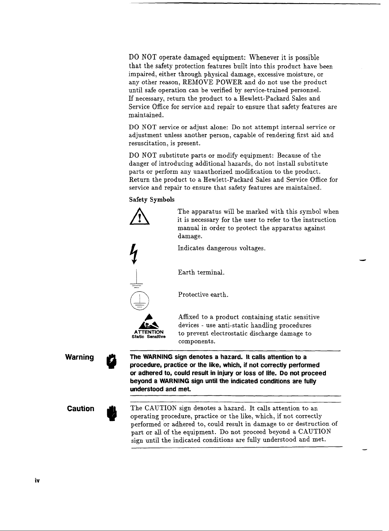
DO
NOT
operate damaged equipment: Whenever it is possible
that the safety protection features built into this product have been
impaired, either through physical damage, excessive moisture, or
any other reason, REMOVE POWER and do not use the product
until safe operation can be verified by service-trained personnel.
If
necessary, return the product to a Hewlett-Packard Sales and
Service Office for service and repair to ensure that safety features are
maintained.
DO NOT service or adjust alone: Do not attempt internal service or
adjustment unless another person, capable of rendering first aid and
resuscitation, is present.
DO NOT substitute parts or modify equipment: Because of the
danger of introducing additional hazards, do not install substitute
parts or perform any unauthorized modification to the product.
Return the product to a Hewlett-Packard Sales and Service Office for
service and repair to ensure that safety features are maintained.
Warning
@
Safety
A
I
The WARNING sign denotes a hazard. It calls attention to a
procedure, practice or the like, which, if not correctly performed
or adhered to, could result in injury or loss of life. Do not proceed
beyond a WARNING sign until the indicated conditions are fully
understood and met.
Symbols
I
-
-
A
ATTENTION
Static Sensltlve
The apparatus will be marked with this symbol when
it is necessary for the user to refer to the instruction
manual in order to protect the apparatus against
damage.
Indicates dangerous voltages.
Earth terminal.
Protective earth.
Affixed to a product containing static sensitive
-
devices
to prevent electrostatic discharge damage to
components.
use anti-static handling procedures
The CAUTION sign denotes a hazard. It calls attention to an
Caution
Artisan Technology Group - Quality Instrumentation ... Guaranteed | (888) 88-SOURCE | www.artisantg.com
1)
operating procedure, practice or the Like, which, if not correctly
performed or adhered to, could result in damage to or destruction
part or
sign until the indicated conditions are fully understood and met.
all
of the equipment. Do not proceed beyond a CAUTION
of
Page 6
Warranty
This Hewlett-Packard product is warranted against defects in
materials and workmanship for a period of three years from date of
shipment. Duration and conditions of warranty for this product may
be superseded when the product is integrated into (becomes a part
of) other HP products. During the warranty period, Hewlett-Packard
Company will, at its option, either repair or replace products which
prove to be defective.
For warranty service or repair, this product must be returned to a
service facility designated by Hewlett-Packard (HP). Buyer shall
prepay shipping charges to
return the product to Buyer. However, Buyer shall pay all shipping
charges, duties, and taxes for products returned to HP from another
country.
HP warrants that its software and firmware designated by HP
for use with a product will execute its programming instructions
when properly installed on that product. HP does not warrant
that the operation of the product, or software, or firmware will be
uninterrupted or error free.
HP
and
HP
shall pay shipping charges to
Limitation
of
Warranty
Exclusive Remedies
The foregoing warranty shall not apply to defects resulting from
improper or inadequate maintenance by Buyer, Buyer-supplied
products or interfacing, unauthorized modification or misuse,
operation outside of the environmental specifications for the product,
or improper site preparation or maintenance.
The design and implementation of any circuit on this product is the
sole responsibility of the Buyer. HP does not warrant the Buyer's
circuitry or malfunctions of HP products that result from the Buyer's
circuitry. In addition, HP does not warrant any damage that occurs
as a result of the Buyer's circuit or any defects that result from
Buyer-supplied products.
NO OTHER WARRANTY IS EXPRESSED OR IMPLIED. HP
SPECIFICALLY DISCLAIMS THE IMPLIED WARRANTIES
MERCHANTABILITY AND FITNESS FOR A PARTICULAR
PURPOSE.
The remedies provided herein are Buyer's sole and exclusive
remedies. Hewlett Packard shall not be liable for any direct, indirect,
special, incidental, or consequential damages whether based on
contract, tort, or any other legal theory.
OF
Artisan Technology Group - Quality Instrumentation ... Guaranteed | (888) 88-SOURCE | www.artisantg.com
Page 7
Assistance
Product maintenance agreements and other customer assistance
agreements are available for Hewlett-Packard products. For any
assistance contact your nearest Hewlett-Packard Sales and Service
Office. Addresses are provided at the back of this manual.
Radio Frequency
Interference Statement
Deutsche Bundespost
Manufacturer's
Declaration
(Federal Republic of Germany only)
Herste]lerbescheinigUng
Hiermit wird bescheinigt, dass dieses Geraet/System
C
betrieben im HP 75000 Series
den Bestimmungen von Postverfuegung 1046 184 funkentstoert ist
Der Deutschen Bundespost wurde das Inverkehrbringen dieses
Geraetes/Systems angezeigt und die Berechtigung zur Ueberpruefung
der Serie auf Einhalt ung der Bestimmungen eingeraeumt
Zusatzinformation fuer Mess- und Testgeraete:
Werden Mess- und Testgeraete mit ungeschirmten Kabeln
und/oder in offenen Messaufbauten verwendet, so ist vom Betreiber
sicherzustellen, dass die Funk-Ent st oerbestimmungen unt er
Betriebsbedingungen an seiner Grundstuecksgrenze eingehalten
werden.
This is to certify that the equipment HP E1440A meets the radio
frequency interference requirements of Directive FTZ 1046184, when
used in the
been notified that this equipment was put into circulation and has
been granted the right to check the product type for compliance with
these requirements.
HP
75000 Series C System. The German Bundespost has
System in Uebereinstimmung mit
HP
E1440A,
.
.
&
Certification
Additional Information for Test and Measurement Equipment:
If
test and measurement equipment is operated with unscreened
cables and/or used for measurements on open set-ups, the user has to
assure that under operating conditions the Radio Interference Limits
are still met at the border of the user's premises.
Hewlett-Packard Company certifies that this product met its
published specifications at the time of shipment from the factory.
Hewlett-Packard further certifies that its calibration measurements
are traceable to the United States National Institute of Standards
and Technology (formerly National Bureau of Standards), to the
extent allowed by that organization's calibration facility, and to the
calibration facilities of other International Standards Organization
members.
Artisan Technology Group - Quality Instrumentation ... Guaranteed | (888) 88-SOURCE | www.artisantg.com
Page 8
--
Introduction
This manual is arranged into five categories:
General Information
General descriptions of the equipment and preparation for use
instructions
-
Chapters 1 and
2
Operating Information
Setting up and sample programs, programming techniques
-
Chapters 3 and
4
Programming Informat ion
Explanation of each software command applicable to the
HP
E1440A
-
Chapter
5,
Appendix B and Appendix
D
Specifications
Appendix
A
Customer Assistance
Sales and Service information: Appendix
F.
vii
Artisan Technology Group - Quality Instrumentation ... Guaranteed | (888) 88-SOURCE | www.artisantg.com
Page 9
Contents
1
.
Getting Started
...............
Using this Chapter
...............
General Description
................
Key Features
.............
Instrument Overview
.............
Physical Description
............
Introduction to Operation
................
Programming
Self Test
..................
...............
The Error Queue
...............
Sample program
........
Checking the Instrument Output
....................
Reset
............
Front Panel Connections
Marker TTL
.................
X-Drive
...................
...................
Pen lift
Sync-Out TTL
................
Output
...................
...............
Ref Out lOMHz
Ref
In
1/1OMHz
...............
.................
AM
(f
5V)
..................
PM
(f
5V)
Front Panel Indicators
.............
Failed
....................
...................
Access
Error
....................
Output On
.................
....................
Caution
2
.
Coniiguring the
HP
E1440A
Using this Chapter
...............
...................
Inspection
Claims and Repackaging
............
.............
Storage and Shipment
Return Shipments to HP
...........
.................
Configuration
..........
The Logical Address Switch
............
Changing Module Settings
Installation
..................
...........
Installing the HP E1440A
Artisan Technology Group - Quality Instrumentation ... Guaranteed | (888) 88-SOURCE | www.artisantg.com
Page 10
3
.
Using
the
HP
E1440A
Using
this Chapter
...............
3-1
Sample Programs
................
3-1
...............
Typical Commands 3-2
.........
[:S 0URceI:OUTPut Command 3-2
:ROSCillator Command
............
3-2
...............
FUNC Command 3-2
...............
FREQ Command 3-3
Programming Examples
.............
3-3
Function Generator
..............
3-3
Multi-Interval Sweep Generator
........
3-4
Multi-Marker Sweep Generator
.........
3-5
Using the Command Group Feature
......
3-6
..............
Sample program 3-6
Using *OPC? to Synchronize the HP E1440A
. .
3-
7
Using *WAI to Synchronize the HP E1440A
...
3-11
4
.
Understanding the HP
E1440A
Using this Chapter
...............
...............
A System Overview
The VXIbus Interface
.............
The Microprocessor System
..........
The Synthesizer
...............
The Function Generator
............
The Output Unit
...............
Amplifier
.................
Attenuator
................
Sweep Generator
..............
Front Panel
................
Planning and Programming
...........
The HP E1440Ain a Test Environment
......
..............
Signal Parameters
FREQuency
................
AMPLitude
................
OFFSet
..................
PHASe
..................
.................
Value Coupling
General
...................
.................
Example
Example of processing value coupled commands
Sweep
....................
Example
:
.................
Functional Coupling
..............
[:SOURce]:FREQuency [:CW]
.........
........
[:SOURce]:ROSCillator :SOURce
......
[:SOURce]:SWEep :TIME:RETRace
..............
Programming Pitfalls
Sweep
....................
Minimal MARKer distances
..........
FUNC TTL and FUNC DC limitations
.....
:VOLT <due> <unit> / :VOLT:UNIT
....
Artisan Technology Group - Quality Instrumentation ... Guaranteed | (888) 88-SOURCE | www.artisantg.com
Page 11
"WAI and *OPC?
..............
4-18
Connections
..................
4-18
5
.
Command
Reference
Using This Chapter
...............
5-1
Command Types
................
5-1
SCPI Command Format
............
5-1
Command Separator
.............
5-1
The SCPI command parser
...........
5-2
Definition of terms
..............
5-2
Common commands
/
SCPI commands
....
5-2
Program message
..............
5-2
Program message unit (command)
......
5-2
Command node
..............
5-3
Optional node
...............
5-3
End node
.................
5-4
Implied root node
.............
5-4
Current base node
.............
5-4
How the parser works
.............
5-4
Example
.................
5-5
Parameters
.................
5-6
Linking Commands
..............
5-7
Common Command Format
..........
5-7
SCPI Command Reference
............
5-8
....................
ABORt 5-8
Subsystem Syntax
..............
5-8
Comments
..................
5-8
..................
Example 5-8
CALibration
..................
5-9
Subsystem Syntax
..............
5-9
..................
Comments 5-9
CAL? Results
................
5-9
...................
INITiate 5-11
Subsystem Syntax
..............
5-11
................
:CONTinuous 5-11
Parameters
.................
5-11
Comments
..................
5-11
[:IMMediate]
.................
5-11
Comments
..................
5-11
...................
OUTPut 5-12
Subsystem Syntax
..............
5-12
..................
[:STATe] 5-12
Parameters
.................
5-12
Comments
..................
5-12
..................
[:STATe]? 5-13
:AMPLify
..................
5-13
High Voltage Option 001
..........
5-13
Parameters
.................
5-13
Comments
..................
5-13
:TTLTrg<n> [:STATe]
.............
5-14
Parameters
.................
5-14
Artisan Technology Group - Quality Instrumentation ... Guaranteed | (888) 88-SOURCE | www.artisantg.com
Page 12

..................
Comments
:TTLTrg<n>:SOURce
............
.................
Parameters
:TTLTrg<n>:AOFF
.............
[:SOURce]
...................
Subsystem Syntax
..............
..................
Comments
.................
[:SOURce]:AM
Subsystem Syntax
..............
.................
Parameters
Comments
..................
.............
[:
SOURce] :FREQuency
Subsystem Syntax
..............
:FREQuency[:CW I :FIXed]
..........
:FREQuency:MODE
.............
:FREQuency :STARt :STOP
..........
:FREQuency:CENTer
.............
:FREQuency:SPAN
..............
..............
[:SOURce]:FUNCtion
..............
Subsystem Syntax
..................
Comments
................
[:SOURce]:LIST
Subsystem Syntax
..............
:LIST:FREQuency
..............
................
:LIST:DWELl
...............
:LIST:SEQuence
[:SOURce] :MARKer[<n>]
...........
..............
Subsystem Syntax
..................
Comments
[:SOURce]:PHASe
...............
Subsystem Syntax
..............
..................
Comments
Example:
..................
.................
[:SOURce]:PM
Subsystem Syntax
..............
Parameters
.................
..................
Comments
.............
[:SOURce] :ROSCillator
Subsystem Syntax
..............
..................
Comments
...............
[:SOURce]:SWEep
Subsystem Syntax
..............
:SWEep:TIME
................
:S WEep:TIME:RETRace
...........
.................
Comments
.STATUS
....................
.............
:STATus:OPERation
Subsystem Syntax
..............
comments
..................
:STATus:QUEStionable
............
:STATus:QUEStionable :FREQUENCY
.....
Artisan Technology Group - Quality Instrumentation ... Guaranteed | (888) 88-SOURCE | www.artisantg.com
Page 13
...............
:STATus:PRESet
...................
:SYSTem
..............
Subsystem Syntax
..............
:SYSTem:ERRor?
..............
:SYSTem:PRESet
.............
:SYSTem:VERSion?
....
IEEE 488.2 Commands for the HP E1440A
....................
*CLS
....................
*ESE
...................
*ESE?
...................
*ESR?
...................
*IDN?
....................
*OPC
...................
*OPC?
....................
*RCL
....................
*RST
....................
*SAV
....................
*SRE
...................
*SRE?
*STB?
...................
...................
*TST?
....................
*WAI
A
.
Specifications
..................
Waveforms
Frequency
...................
..........
Main Signal Output (Typical)
...............
Amplitude into 50fl
............
Sinewave Spectral Purity
.......
Squarewave Characteristics (Typical)
..........
Triangle/Ramp Characteristics
...................
DC Offset
Phase Offset
..................
Sinewave Amplitude Modulation (Typical)
.....
...........
Phase Modulation (Typical)
................
Frequency Sweep
...........
Auxiliary Outputs (Typical)
...........
Auxilliary Inputs (Typical)
VXIbus Interface Capabilities
..........
Option
001
High-Voltage Output Amplifier
....
General (Typical refer to VXI System Specification)
Artisan Technology Group - Quality Instrumentation ... Guaranteed | (888) 88-SOURCE | www.artisantg.com
Page 14
B
.
Register Programming
Registers
...................
...............
Status Reporting
.................
Error Queue
Status Registers
................
Using the Registers
...............
...............
Sample Program
.................
Program
Performance tests
Introduction
.................*
Test Record
..................
Recommended Test Equipment
..........
Functional Verification Tests
...........
Performing a Self-test
.............
Starting the test
..............
Reading the Error Queue
..........
Example program
.............
Checking the Instrument Output
........
Operational Verification Tests
..........
Without a Controller
.............
With a Controller
..............
Performance Verification Tests
..........
.................
Introduction
Harmonic Distortion
.............
Specifications
...............
............
Equipment Required
Procedure
.................
High-Voltage Output (Option 001)
......
Spurious Signal
...............
...............
Specifications
Equipment Required
............
Mixer Spurious Procedure
..........
Close-in Spurious (Fractional N Spurs) Procedure
Integrated Phase Noise
............
...............
Specifications
............
Equipment Required
Procedure
.................
Frequency Accuracy
.............
...............
Specifications
............
Equipment Required
Procedure
.................
Phase Increment Accuracy
...........
Specifications
...............
............
Equipment Required
.................
Procedure
.............
Amplitude Accuracy
Specifications
...............
Equipment Required
............
Amplitude Accuracy at Frequencies upto 100
kHz
Procedure
...............
Artisan Technology Group - Quality Instrumentation ... Guaranteed | (888) 88-SOURCE | www.artisantg.com
Page 15
......
High-Voltage Output (Option 001)
Amplitude Accuracy (Frequencies
>
100
kHz)
.
......
High-Voltage Output (Option 001)
.........
DC Offset Accuracy (DC only)
...............
Specifications
............
Equipment Required
.................
Procedure
.............
Attenuator Test
......
High-Voltage Output (Option 001)
.....
DC Offset Accuracy with AC Functions
...............
Specifications
............
Equipment Required
.................
Procedure
..............
Triangle Linearity
...............
Specifications
............
Equipment Required
.................
Procedure
.................
Test Facility
:
................
Test Conditions
:
..............
Installed Options
:
............
Ambient Temperature
:
..............
Relative Humidity
:
Line Frequency
:
...............
Special Notes
:
.................
Test Equipment Used
:
.............
Harmonic Distortion
..............
Spurious Signals
................
Integrated Phase Noise
.............
Frequency Accuracy
..............
Phase Increment Accuracy
............
Amplitude Accuracy
..............
DC Offset Accuracy (DC only)
..........
DC Offset Accuracy with AC Function
......
Triangle Linearity
...............
D
.
Command Quick Reference
..................
Introduction
E
.
Error Messages
..................
Introduction
..................
Message List
Artisan Technology Group - Quality Instrumentation ... Guaranteed | (888) 88-SOURCE | www.artisantg.com
Page 16

F
.
Sales
and
Service Offices
Information
..................
F-
1
Asia
....................
F-
1
Canada
...................
F-1
Eastern Europe
...............
F-
1
Northern Europe ...............
F-
1
South East Europe ..............
F-
1
Middle East and Central Africa
........
F-
2
United Kingdom
...............
F-2
United States of America
...........
F-2
Eastern USA .................
F-2
Midwestern USA
...............
F-2
Southern USA
................
F-2
Western USA
................
F-2
Other International Areas
............
F-3
Index
Artisan Technology Group - Quality Instrumentation ... Guaranteed | (888) 88-SOURCE | www.artisantg.com
Page 17
Figures
1.1
.
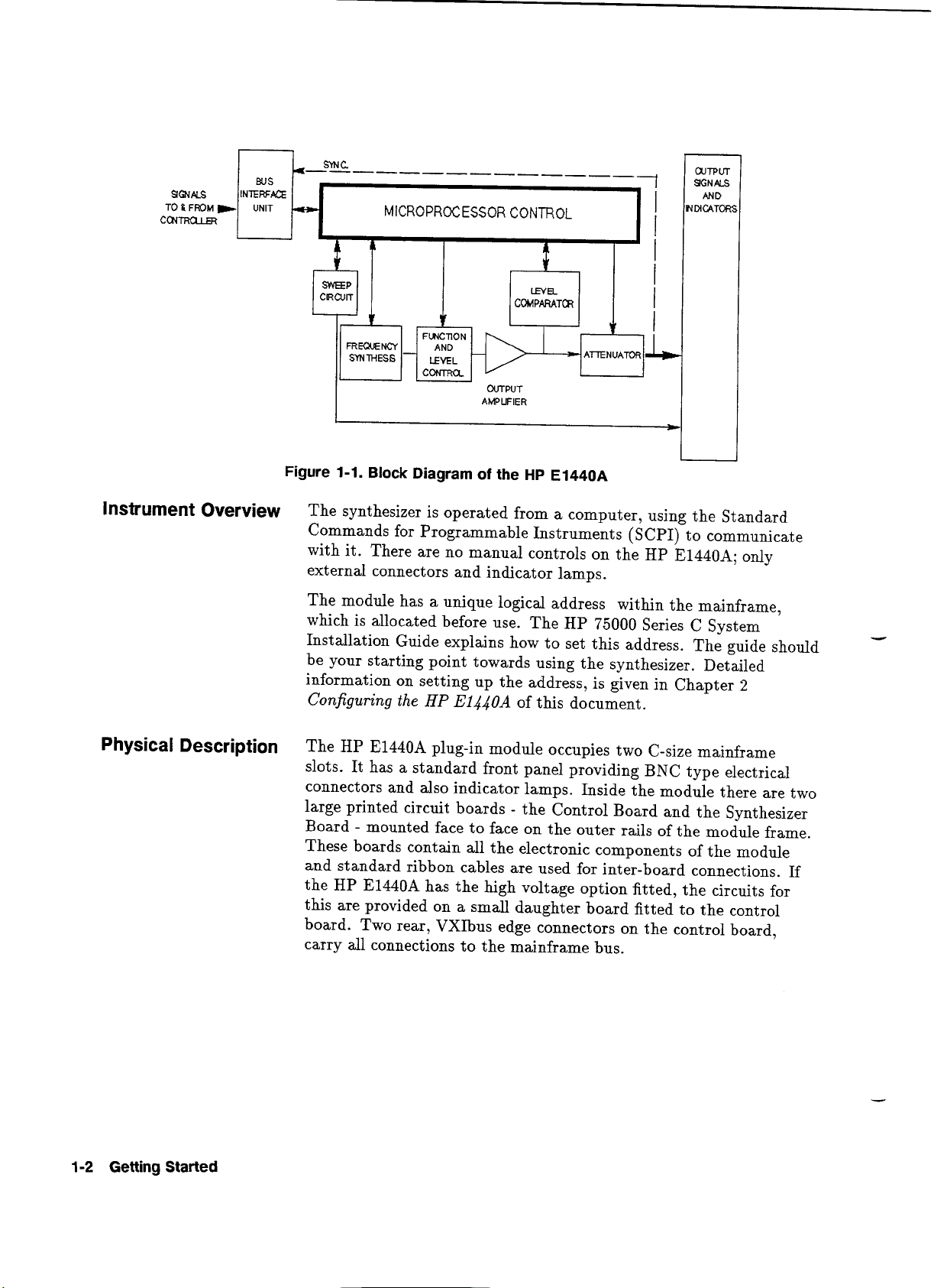
Block Diagram of the HP E1440A
.......
1-2
1.2
.
HP E1440A Front panel
............
1-6
2.1
.
Address Switch and Jumper Location
......
2-3
2.2 . Address Switch Settings
............
2-4
2.3
.
Jumper JlOl Links Settings
..........
2-5
4.1
.
Simplified Block Diagram
...........
4-1
4.2
.
Synthesizer Block Diagram
..........
4-2
4.3
.
Handling of Value Coupled Commands
.....
4-12
B.1
.
Status Register Subset
............
B-2
C.1
.
Service Switch
................
C- 7
C.2
.
Example Service Switch Setting
........
C-7
C.3
.
Harmonic Distortion Verification Test Set-Up
(High-Voltage Output)
...........
C-12
C.4
.
Mixer Spurious Test Set-Up
..........
C-14
C.5
.
Integrated Phase Noise Test Set-Up
.......
C-17
C.6
.
Phase Increment Accuracy Test Set-Up
.....
C-20
C.7
.
Function Amplitude Accuracy Test Set-Up
...
C-23
C.8
.
High voltage sinewave accuracy test set.up
....
C-26
C.9
.
Function Amplitude Accuracy Test Set-Up
(High-Voltage Output)
...........
C-27
C.10
.
Test set-up for Amplitude Accuracy Adjustment
(Frequency
>
100 kHz)
...........
C-28
C.11
.
500 0 300 pF loadlvoltage divider
.......
C-30
C.12
.
DC Offset Test Set-Up
............
C-34
.........
C.13 . Triangle Linearity Test Set-Up
C-36
Artisan Technology Group - Quality Instrumentation ... Guaranteed | (888) 88-SOURCE | www.artisantg.com
Page 18
Tables
1.1
. Instrument Reset State
............
3.1
. Values for FUNC Command
..........
3.2 . Frequency Controls
..............
4-
1
. Frequency Ranges
..............
4.2 . Amplitude Limits of AC Functions
.......
4.3 . High-Voltage Output Amplitudes
........
4.4 . Maximum DC Offset with any AC Function
...
4.5 . El440 Command Group Assignment
......
4.6 . Illegal El440 Commands in FREQ:MODE LIST
/
.................
SWEEP
5.1
. Operation Status Register
...........
5.2 . Questionable Status Register
..........
5.3 . Questionable Frequency Register
........
5.4 . Common Command Summary
.........
5.5 . Reset State (Standard Setting)
.........
C.1 . Recommended Test Equipment for Tests
....
.
..............
C.2 Self-test result bits
C.3
. Service Switch Parameter Settings
.......
.......................
C.4
Artisan Technology Group - Quality Instrumentation ... Guaranteed | (888) 88-SOURCE | www.artisantg.com
Page 19
Getting Started
Using this Chapter
This chapter introduces you to the VXIbus, HP E1440A Synthesized
FunctionJSweep Generator. The main sections of the chapter are:
..............................................
rn
General Description
1-1
Introduction to Operation
....................................
1-3
Front Panel
........................................................
1-6
General Description
The HP E1440A Synthesized FunctionJSweep Generator is a
multi-task signal generator, built as a C-size (double slot) plug-in
module, for use with other similar modules in a VXI mainframe. It
can be used as:
a reference source
Produces a sine wave of a specified frequency, amplitude, DC offset
and phase.
a function generator
Produces various waveforms at a specified frequency, amplitude,
DC offset and phase.
a sweep generator
Produces logarithmic and linear frequency sweeps.
Key
Features
Key features of the HP E1440A are as follows:
5
different waveforms can be output
Variable offsets and amplitudes
rn
Can be used as a DC source
rn
Multi-interval or multi-marker sweep capabilities
rn
Sweep sequencing
rn
Combined linear and logarithmic sweeps
rn
Phase-continuous sweep
Message based module (responds to
high
level ASCII SCPI
commands)
rn
Save/recall instrument settings
rn
Compatible with VXIbus mainframe unit and associated modules
Getting
Started
1-1
Artisan Technology Group - Quality Instrumentation ... Guaranteed | (888) 88-SOURCE | www.artisantg.com
Page 20
Artisan Technology Group - Quality Instrumentation ... Guaranteed | (888) 88-SOURCE | www.artisantg.com
Page 21
-
Introduction to
Operation
This section contains information on checking communication
between the synthesizer, mainframe and the computer. It includes
information on returning the synthesizer to a known operating state
if
(reset), should programming errors occur or
a restart is necessary.
Note
Programming
Before the
adjustments may need to be made to the module and then it has
to be installed in the mainframe. Details of these tasks are given in
Chapter 2
The HP El4408 has been designed so that it can be controlled by
an external computer. Its operations are therefore performed by a
series of programmable commands using SCPI. There are no manual
controls.
This section gives only brief general information on how to control
the HP
the commands specific to the HP E1440A, see Appendix
Quick
Programming information in this chapter is restricted to HP
E1440A specifics, and assumes that you are familiar with VXIbus or
VMEbus intrinsics.If you are not familiar with these, then refer to
industry standard publications about the VMEbus and the following
publications:
rn
The "VXIbus System Specification7' published by The VXIbus
Consortium, Inc.
HP
E1440A can be used, some system configuration
Configuring the
E1440A using a controller module. For a short form list of
Reference.
HP
E1440A.
D
Command
Self
Note
Test
)46
rn
ANSIIIEEE-488.2-1987, "Digital Interface for Programmable
Instrumentation" published by the Institute of Electrical and
Electronic Engineers
A complete syntax list of the HP E1440A programming commands
can be found in Chapter
Once the mainframe and module have been powered up (see Chapter
2 for instructions on how to check and set the module address),
the synthesizer is ready for use. During power-up, the HP
automatically executes an internal check and makes sure it is able to
communicate with the back plane of the VXI mainframe.
The HP E1440A has a "Failed" indicator that remains on if the
synthesizer is not able to communicate with the controller.
This self test routine can also be executed on command and therefore
sending the self test command is an easy way to check that you
are correctly addressing the synthesizer. Self test is also useful in
locating intermittent problems which might occur during operation.
5
Command Syntax Reference.
E1440A
Getting
Artisan Technology Group - Quality Instrumentation ... Guaranteed | (888) 88-SOURCE | www.artisantg.com
Started
1-3
Page 22
The command used to execute self test is:
On execution of this command, the synthesizer performs a self test
routine which is built into the module firmware. The result of the self
test is placed in the error queue, which is subsequently interrogated
by the controller.
*TST?
The
Error
Queue
Sample program
When an error occurs during operation, a suitable error code and
message are stored in the synthesizer error queue. These errors can
be read out using the
(zero) means there are no more errors. The error queue can store up
to 30 codes and messages on a 'first in first out'
messages are described in Appendix
The following BASIC program executes self test; this program
assumes the mainframe is at a primary interface address
the synthesizer is at a secondary address of
assumes that an
!Send the self-test command to the synthesizer
I
'SYS:ERR?'command. A returned value of 0
(FIFO)
E
Error
Messages
11.
The program also
HP
9000 Series 200/300 computer is used.
basis. Error
of
09 and
OUTPUT 7091 1 ; ll*TST?l'
I
!Enter
I
and
display the self test code
ENTER70911;A
PRINT
!
A
!Reset the synthesizer
I
OUTPUT 709 11 ; *RSTI1
END
Note
Checking the
Instrument Output
1-4
Getting
Started
3
Last line of program
After testing, always reset the synthesizer to a known state.
After using the above program to reset the
test with an oscilloscope will check that the module is functional.
Connect an oscilloscope to the output BNC and then send the
following short program:
!
10
20
30
Set frequency value
!
OUTPUT 7091
!
!
Set function to sinewave
OUTPUT 70911
!
!
Set output level to
!
1
;
"FREQ
;
"FUNC
lE3
SIN"
"
1
V
HP
E1440A, a simple
OUTPUT 70911 ; "VOLT 1"
Artisan Technology Group - Quality Instrumentation ... Guaranteed | (888) 88-SOURCE | www.artisantg.com
Page 23
110
!
120
Switch
!
130
140 OUTPUT
END
150
on
the
70911
output
;
"OUTP ON"
Reset
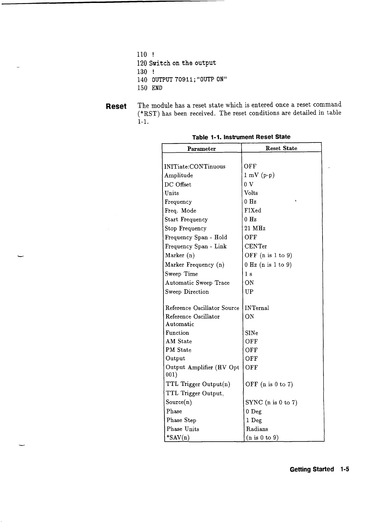
The module has a reset state which is entered once a reset command
(*RST)
has been received. The reset conditions are detailed in table
-
N1Tiate:CONTinuous
lmplitude
IC Offset
Tnits
?requenc y
?req. Mode
Start Frequency
stop Frequency
Frequency Span
Frequency Span
Marker (n)
Marker Frequency (n)
Sweep Time
Automatic Sweep Trace
Sweep Direction
Table 1-1. Instrument Reset State
Parameter
-
-
Hold
Link
IFF
:
1
dolts
1
FIXed
3
21
3FF
SENTer
3FF (n
I Hz
I
3N
UP
Reset State
mV
(P-P)
V
Hz
Hz
MHz
(n is 1 to 9)
s
is
1
to 9)
Reference Oscillator Source
Reference Oscillator
Automatic
Function
AM State
PM
State
Output
(HV
Output Amplifier
001)
TTL
Trigger Output(n)
TTL Trigger Output,
Source(n)
Phase
Phase Step
Phase Units
*
SAV(n)
Opt
SINe
OFF
OFF
OFF
OFF
OFF (n is
SYNC (n is 0 to
0 Deg
1
Deg
Radians
(n is
0 to
0
9)
to
7)
7)
Getting Started
1-5
Artisan Technology Group - Quality Instrumentation ... Guaranteed | (888) 88-SOURCE | www.artisantg.com
Page 24
Front
Panel
Connections
The
HP
E1440A
front panel is illustrated below
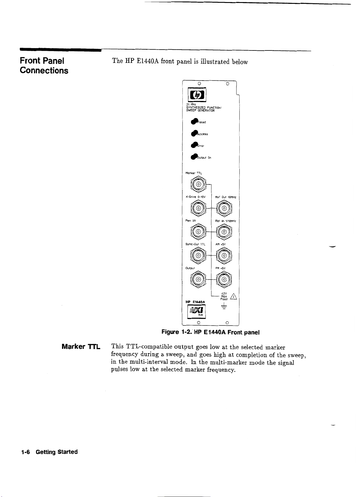
Faled
Access
Error
~utput
On
0
21 MHz
SYNTHESIZED PJNCTIONI
SWEEP GENERATOR
Wrker
TTL
@
(-Dnve
0-10V
@
'en
lift
wc-Out
TTL
@
utput
@
IP
E1440A
W]
,-.
Ref
Out lotiHz
@
Ref
In
11lOMHr
@
@
@
-
6%
Float
i
-
Figure
1-2.'HP
E1440A
Front panel
Marker
TTL
This TTL-compatible output goes low at the selected marker
frequency during a sweep, and goes high at completion of the sweep,
in the multi-interval mode.
In
the multi-marker mode the signal
pulses low at the selected marker frequency.
1-6
Getting Started
Artisan Technology Group - Quality Instrumentation ... Guaranteed | (888) 88-SOURCE | www.artisantg.com
Page 25
X-Drive
This output ramps from 0 V to 10 V during a sweep.
Pen
lift
This output provides a pen lift signal for a plotter at the end of a
signal.
Sync-Out
TTL
A
TTL
compatible square wave synchronized output signal, is
available at this connector. The signal is synchronized with the
output signal crossover point (zero volts or
DC
offset voltage). The
connector functions for frequencies up to 60 MHz.
Output
Standard output impedance is 50R. High-voltage option (001) output
impedance is nominally
<
3Q
at
DC,
and < 10R at 1 MHz.
Ref
Out
10MHz
A 10 MHz signal from the
HP
E1440A reference circuits is available
here.
Ref
In
1/1OMHz
This external frequency reference may be used to phase-lock the
internal 30 MHz oscillator.
AM
(f
5V)
An Amplitude Modulation input reference can be connected here for
input to the synthesizer circuit. Range is
*5
volts in all modes, i.e.
sine, square, triangle, ramps.
PM
(f
5V)
A Phase Modulation input reference can be connected here for input
to the synthesizer circuit. Range is
f
5
volts in all modes, i.e. sine,
square, triangle, ramps.
Front Panel
Indicators
Failed
This red lamp illuminates as soon as power is applied to the module.
The module then checks out it's connections to the VXIbus i.e. it
checks that it is able to communicate with the mainframe. When
that check is verified, the module extinguished the Failed lamp.
Note
Absence of the
Failed
lamp does not necessarily mean that the
module is suit able for use.
Getting
Started
1-7
Artisan Technology Group - Quality Instrumentation ... Guaranteed | (888) 88-SOURCE | www.artisantg.com
Page 26
Access
This green lamp flickers when the
communication between the module and mainframe is taking place.
HP
E1440A
is in use, showing
that
Caution
Error
Output
On
This red lamp illuminates to indicate there are error codes queued in
the
store, ready for collection
This green lamp illuminates when there is a signal available at the
output connector.
The outputs and externally applied voltages may be
floating at upto
exist
The
input/output connectors should not be subjected
to overload. Carefully note the max. applicable
voltage for each connector as specified in Appendix A
to this manual.
by
the controller.
42
V.
Risk of electric shock may
1-8
Getting
Started
Artisan Technology Group - Quality Instrumentation ... Guaranteed | (888) 88-SOURCE | www.artisantg.com
Page 27
Configuring
the
HP
E1440A
Using this Chapter
This chapter provides instructions on preparation for use and how
to install the HP
E1440A
module. It also includes information
about initial inspection and damage claims, packaging, storage and
shipment.
Before operation, the instrument and manual, including the red
safety page, should be reviewed for safety markings and instructions.
These must then be observed to ensure safe operation and to
maintain the instrument in safe condition.
............................................................
Inspection
2-1
........................................................
Configuration
2-2
Changing Module Settings
...................................
2-4
Installation
..........................................................
2-5
-
l
nspection
Warning
Inspect the shipping container for damage. If the container or
cushioning is damaged, it should be kept until the contents of the
shipment have been checked for completeness and the instrument has
been verified both mechanically and electrically.
Procedures for checking the operation of the instrument are given
in Chapter
1
Getting
Started.
If the contents are incomplete,
mechanical damage or defect is apparent, or if an instrument does
not pass the operator's checks, notify the nearest Hewlett-Packard
office. Keep the shipping materials for carrier's inspection. The
HP office will arrange for repair or replacement without awaiting
settlement.
To avoid hazardous electrical shock, do not perform electrical tests
0
when there are signs of shipping damage to any portion of the outer
enclosure (covers, panels, etc.).
Configuring the
HP
E1440A
2-1
Artisan Technology Group - Quality Instrumentation ... Guaranteed | (888) 88-SOURCE | www.artisantg.com
Page 28
Claims and
Repackaging
If physical damage is evident or if the instrument does not meet
specification when received, notify the carrier and the nearest
Hewlett-Packard Service Office. The Sales/Service Office will arrange
for repair or replacement of the unit without waiting for settlement of
a claim against the carrier.
Storage and Shipment
Return Shipments to
HP
The instrument can be stored or shipped at temperatures between
-40°C
and
f75"C.
The instrument should be protected from
temperature extremes which may cause condensation within it.
If the instrument is to be shipped to a Hewlett-Packard Sales/Service
F),
Office (see Appendix
attach a tag showing owner, return address,
model number and full serial number and the type of service
required.
The original shipping carton and packing material may be re-usable,
but the Hewlett-Packard Sales/Service Office will also provide
information and recommendations on
materials to be used if
the original packing is no longer available or reusable. General
instructions for repacking are as follows:
1.
Wrap instrument in heavy paper or plastic.
2.
Use strong shipping container. A double wall carton is adequate.
3.
Use enough shock-absorbing material
all
sides of the instrument to provide a firm cushion and prevent
(3
to 4 inch layer) around
movement inside container.
4.
Seal shipping container securely.
5.
Mark shipping container
FRAGILE
to encourage careful handling.
I
Configuration
2-2
Configuring
the
HP
E1440A
6.
In any correspondence, refer to instrument by model number and
serial number.
As detailed in the VXIbus Mainframe System Installation Guide,
each plug-in module has a row of switches which are used to set the
logical address of the module. The mainframe operating system uses
these unique addresses, to combine different modules into virtual
is
instruments within the mainframe slots. The module
addressed by
the computer program, using the logical address to distinguish it
from other modules in the system.
4
ATTENTION
Static Sensltlve
ATTENTION STATIC SENSITIVE Handle the
module, only at 'Static Safe' work stations
!
Artisan Technology Group - Quality Instrumentation ... Guaranteed | (888) 88-SOURCE | www.artisantg.com
Page 29
The
Logical
Address
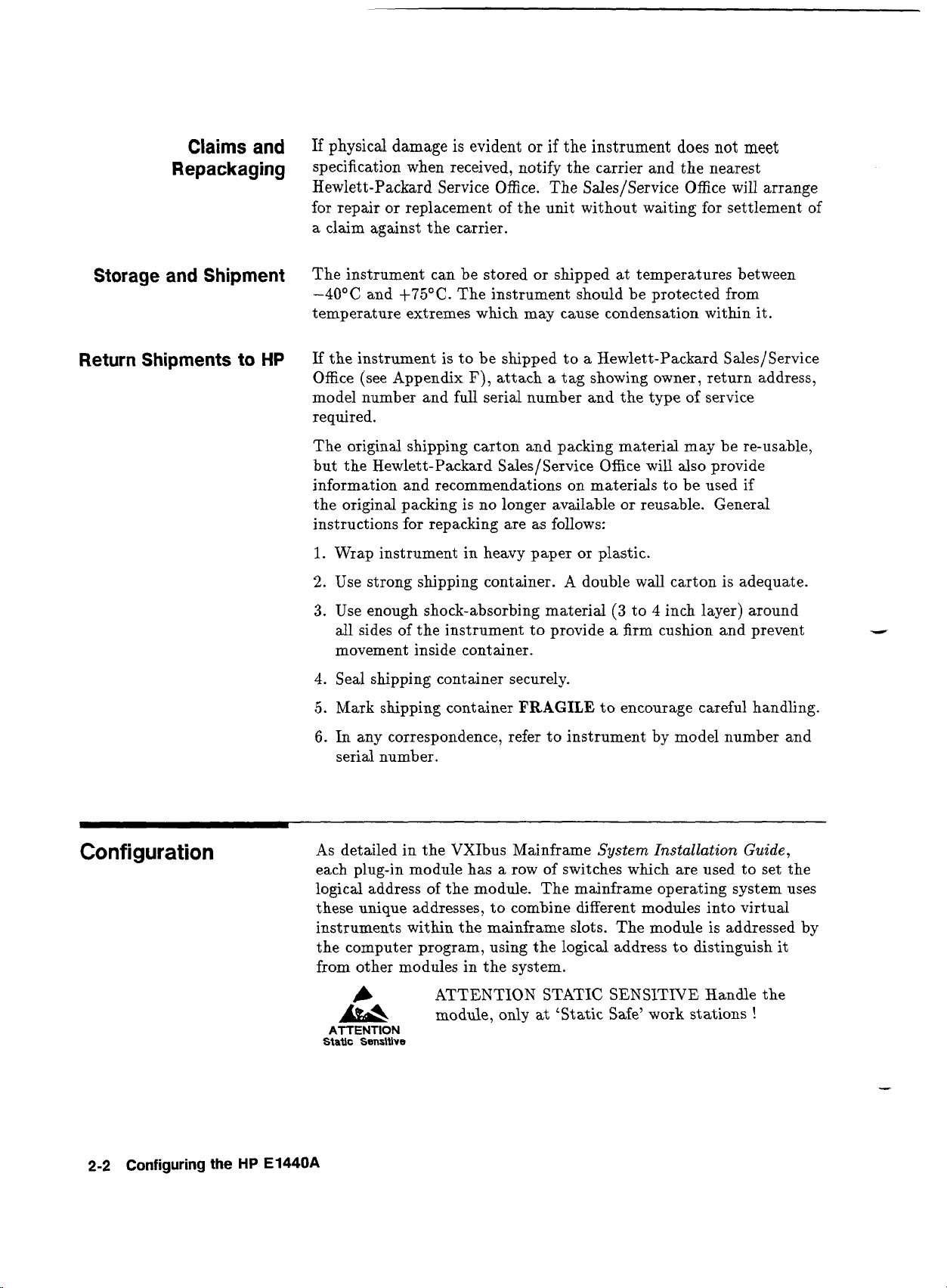
Figure 2-1 shows the location of the
HP
E1440A
logical address
Switch
switch. Access to alter the switch settings may be gained through a
cutout in the module cover.
Logical
Address
Switch
\
/
Cutaway
view
J101
to
J106
(on
rear)
Figure
2-1.
Address Switch and Jumper Location
The Logical Address switch has a factory setting of 88 which is
equivalent to a secondary address of
11.
Figure
2-2
shows how a primary address setting of 88, transposes
to a secondary address of
11
by shifting three places (ignoring the
first three switches). Make sure you apply this rule when altering the
switch setting to a number of your choice. Remember, the module
secondary address must be the one present in
all
control programs for
this module.
Configuring the
HP
E1440A
2-3
Artisan Technology Group - Quality Instrumentation ... Guaranteed | (888) 88-SOURCE | www.artisantg.com
Page 30
,
Service
Switch - DO
NOT
ALTER
,
Logical
Address
128
switch
MSB LSB
MSB LSB
Figure
2-2.
Address
Switch
Settings
This view of the switch settings is the one you will see when looking
directly into the top of the module. The switch positions are shown
from the same viewpoint.
Note
If
there is no other identical
HP
E1440A module in the mainframe
with this address, and this factory set address does not conflict with
one of the other modules, then the factory setting may be left as it is
set.
A
The service switch beside the logical address switch
-
is factory set as shown and is for use by service
personnel only. It must not be altered!
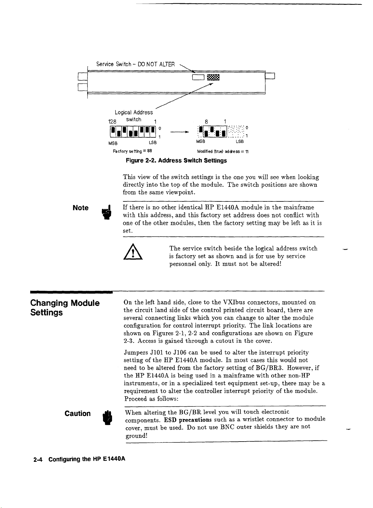
Changing
Settings
Module
On the left hand side, close to the VXIbus connectors, mounted on
the circuit land side of the control printed circuit board, there are
several connecting links which you can change to alter the module
configuration for control interrupt priority. The link locations are
shown on Figures 2-1,
2-2
and configurations are shown on Figure
2-3. Access is gained through
a
cutout in the cover.
Jumpers JlOl to J106 can be used to alter the interrupt priority
setting of the HP E1440A module.
In
most cases this would not
need to be altered from the factory setting of
BG/BR3.
However, if
the
HP
E1440A is being used in a mainframe with other non-HP
instruments, or in a specialized. test equipment set-up, there may be a
requirement to alter the controller interrupt priority of the module.
Proceed as follows:
When altering the
BG/BR
level you will touch electronic
components.
ESD
precautions
such as a wristlet connector to module
cover, must be used. Do not use
BNC
outer shields they are not
ground!
2-4
Configuring
the
HP
E1440A
Artisan Technology Group - Quality Instrumentation ... Guaranteed | (888) 88-SOURCE | www.artisantg.com
Page 31

1.
Place module on a bench with the jumper access cutout
uppermost
2.
Refer to figure
2-3
and remove the single jumper from the column
where you want the full column jumpered according to the
BG/BR
level you require
3.
Move the three jumpers that are together, across to the column
you have just emptied
4.
Place the single jumper in the vacated column in line with the
other two single jumpers
5.
Check that the final jumper positions are correct for the
BG/BR
level you require and that
all
jumpers are secure on their pins
3210 3210 3210 3210
BGiBRO BGIBR1 BGiBR2
BGiBR3
(Factory setting)
Figure 2-3. Jumper 5101 Links Settings
A
The Jumper positions are factory set as shown. Do
LA
not alter unless absolutely necessary.
l
nstallation
In
addition to C-Size modules, the mainframe also accepts A- and
B-Size modules. If you intend using the
HP
E1440A with these
smaller size modules, it is better to install them first. Refer to the
mainframe manual for details.
SHOCK HAZARD. Remove all sources of power from the mainframe
Warning
@
before removing or installing the HP E1440A module.
A
ATTENTION STATIC SENSITIVE Handle the
module, only at 'Static Safe' work stations
!
ATTENTION
Static
Sensitive
Configuring the HP E1440A
2-5
Artisan Technology Group - Quality Instrumentation ... Guaranteed | (888) 88-SOURCE | www.artisantg.com
Page 32

Installing the
E
IUOA
HP
Choose the mainframe location for the module and place the module
card edges into the front mainframe guides (top and bottom). Fit the
module as follows:
a
Slide the module towards the rear of the mainframe until the
connectors approach the backplane
I
Check that the module connectors align with the backplane
receptacles
Caution
#I
There are
receptacles, which could be damaged or altered, if the module
connectors are pushed against them
Carefully push the module home so that the connectors mate
solidly with the back plane receptacles, the screening fingers rest
comfortably against the adjacent module, and the front panel is
flush against the front bar of the mainframe
rn
Secure the module using the captive screws in the front panel to
lock the module into the mainframe
Power can now be restored to the mainframe.
DIL
switches on the backplane beside the connector
2-6
Configuring the
HP
E1440A
Artisan Technology Group - Quality Instrumentation ... Guaranteed | (888) 88-SOURCE | www.artisantg.com
Page 33

Using
the
HP
E1440A
Using
this
Chapter
The purpose of this chapter is to provide example programs that
show you how to operate the synthesizer. With minor modifications,
these programs can also be used for many of your applications. The
examples in this chapter include:
Function Generator
....................................................
3-3
Multi-Interval Sweep Generator
.................................
3-4
Command Group Feature
..........................................
3-5
Synchronizing the
E1440A
.........................................
3-
7
Sample Programs
This chapter provides only basic programming information for the
HP
E1440A.
More advanced examples may be found in Chapter
4
Understanding
the
HP
Eld40A
After power-on of the VXI mainframe, check that the
Failed
lamp
on the HP
E1440A
front panel, has extinguished. This means that
the microprocessor within the unit, has checked that it is connected
properly to the VXIbus and can operate with the rest of the system.
To check if the controller and the HP
E1440A
are talking with each
other, send a query and look at the response from the
HP
E1440A.
For example:
Program
Result
10
DIM
A$[2551
Dimensions
A$.
20
OUTPUT
70911;
Queries the type of output waveform the
"
:
FUNC?"
HP
E1440A
is set to.
30
ENTER
70911;A$
The HP
E1440A
waveform type is received by
the
controller.
40
PRINT
A$
The type is displayed.
50
END
Program end.
The display should read SIN (Sine wave) because after a reset, that is
what the HP
E1440A
is set to.
Note
Whilst messages (Command strings and responses) are being
exchanged between the
HP
E1440A
and the controller, the
Access
lamp will flash intermittently on the front panel.
Using
the
HP
E1440A
3-1
Artisan Technology Group - Quality Instrumentation ... Guaranteed | (888) 88-SOURCE | www.artisantg.com
Page 34

If
the function is not shown, the first thing to check is that the
HP
address set on the
E1440A is the same as the one you are using
(in this case 11). Details of address set up are given in Chapter
Configuring
the
HP
EI&OA.
2
Typical
Commands
[:SOURce]:OUTPut
Command
:ROSCiliator Command
FUNC
Command
Any commands shown here in square
([
I)
brackets, are optional.
They are included to help your understanding of the command logic.
The
[:SOUR]:OUTP ON/OFF command is used to switch a relay
that applies the instrument output signal to the output connector, or
isolates the connector. The command switches the output signal.
The
HP
E1440A may use alternative reference oscillators as follows:
Source Keyword Description
:ROSC:SOUR
An internal 30 MHz crystal
INTernal
A
:ROSC:SOUR
EXTernal
:ROSC:SOUR
CLK
10
reference input to the front panel connector in
the range
A
10
(available to
1
MHz to 10 MHz
MHz signal taken from the VXIbus
all
mainframe modules)'
The function, FUNC[:SHAPe], command allows you to set the shape
and frequency of your waveform.
Table
3-1.
Values
for
FUNC
Command
3-2
Using
the
HP
E1440A
Function
DC
SINusoid
SQUare
TRIangle
RUP
(Pos. slope ramp)
RDOWn
TTL
(Neg.
slope ramp)
1
pHz
1
pHz
1
pHz
1
pHz
1
pHz
1
pHz
Range
DC
to
to
to
to
to
to
level
21
11
11
11
11
60
MHz
MHz
kHz
kHz
kHz
MHz
Artisan Technology Group - Quality Instrumentation ... Guaranteed | (888) 88-SOURCE | www.artisantg.com
Page 35

FREQ
Command
The frequency sweep controls are as follows:
Table
3-2.
Frequency
Controls
Range
CW,
FIXed,
SWEep or
LIST
numeric value sets start frequency
numeric value sets stop frequency
numeric value sets center frequency
numeric value sets frequency span
Note
3
Changing the span alters the start and stop frequencies but not
center
Programming
The following sections give programming examples for the
Examples
HP E1440A. The examples are divided into three different sections,
a simple function generator, a multi-interval sweep generator and
a multi-marker sweep generator.
All
of the programs assume the
following:
rn
an HP 9000, Series 200 or 300 Computer as controller
rn
that BASIC is the programming language
rn
that the HP E1440A is preset to HP-IB address
11
rn
that the slot 0 commander (E1405) is set to primary HP-IB
address 9
Function Generator
The following program shows an example of how to program the
HP
E1440A as a function generator. The program shows how to:
1.
Clear all devices (resets E1440A)
2.
Set the waveform as a square wave
3. Set the frequency to 10
kHz
4. Set the amplitude to 1 V(p-p)
5.
Set the DC offset to 4.5 V
6.
Set the phase to
45'
7.
Switch the output on
Using
the
HP
E1440A
3-3
Artisan Technology Group - Quality Instrumentation ... Guaranteed | (888) 88-SOURCE | www.artisantg.com
Page 36

Program
10
OUTPUT 70911; "*RST;*CLS"
20
OUTPUT 70911; ":SOUR:WC
sqult
30
OUTPUT 70911; ":FREQ 10000"
40
OUTPUT 70911; ":VOLT
1"
50
OUTPUT 70911; ":VOLT:OFFS
4.5"
60
OUTPUT 70911; ":PHAS 45 DEG"
70
OUTPUT 709 11 ; I' : OUTP ON"
Result
Clears all status registers.
selects square wave
sets frequency to 10 kHz
sets amplitude to
1
volt
sets offset to 4.5 volts
sets phase to
45'
switches output signal to the front
panel
BNC
connector
Program end.
Note
Lines
20
to 70 could have been sent as one composite instruction
$
OUlPUT70911;":SOUR:FIMCSQU;:FREQ10000;:VOLT1;:VOLT:OFFS
4.5
;
:
PHAS
45
DEG"
Multi-Interval Sweep
Generator
The following program shows
an
example of how to program the
HP
E1440A as a multi-interval sweep generator. The program
assumes that the amplitude, waveform,
DC
offset and phase, are the
same as set in the previous example, retrace time is set to
5
seconds
and the sweep is to run continuously. The program then shows how
to set five sweep intervals with the following parameters:
Interval
1:
start frequency
1
kHz
stop frequency 3 kHz
marker frequency
2
kHz
sweep time
1
sec.
sweep mode linear
Interval
2
start frequency 500 Hz
stop frequency 10 kHz
sweep time
1
sec.
sweep mode logarithmic
Interval 3 start frequency
2
kHz
stop frequency
4
kHz
marker frequency
3
kHz
sweep time
1
sec.
sweep mode linear
Interval
4
start frequency 900 Hz
stop frequency 10 kHz
sweep time
1
sec.
sweep mode logarithmic
Interval
5:
start frequency 3 kHz
stop frequency 5 kHz
marker frequency
4
kHz
sweep time
1
sec.
sweep
mode
linear
3-4
Using
the
HP
E1440A
Artisan Technology Group - Quality Instrumentation ... Guaranteed | (888) 88-SOURCE | www.artisantg.com
Page 37

10
OUTPUT 70911; ":LIST:FREQ:STAR 1000,500,2000,900,3000"
20
OUTPUT 70911; ":LIST:FREQ:STOP 3000,10000,4000,10000,5000"
30
OUTPUT 70911; ":LIST:FREQ:MARK 2000,200,3000,500,4000"
40
OUTPUT 70911; I1:LIST:FREQ:MARK:STAT ON,OFF,ON,OFF,ON"
50
OUTPUT 70911; ":LIST:FREQ:SPAC LIN,LOG,LIN,LOG,LIN"
60
OUTPUT 70911; ":LIST:DWELL 1"
70
OUTPUT 70911; ":SWE:RTIM 5"
80
OUTPUT 70911; ":LIST:SEQ (1:5)"
90
OUTPUT 70911; ":FREQ:MODE LIST"
100
OUTPUT 70911; ":INIT:CONT ON"
110
END
Multi-Marker Sweep
The following program shows an example of how to program the
Generator
HP
E1440A
as a multi-marker sweep generator. The program sets up
the following continuous sweep:
Interval Start Frequency 1.0 kHz
Interval
Stop
Frequency 5.0 kHz
Interval Sweep Time 1.0
s
with the following markers:
Marker 1 1.5 kHz
Marker 2 2.0 kHz
Marker 3 2.5 kHz
Marker 4 3.0 kHz
Marker 5 3.5 kHz
Marker
6
4.0 kHz
Marker 7 4.5 kHz
1
OUTPUT 70911
;
It
:
FREQ : STAR 1E3"
2
OUTPUT 709 11
;
It
:
FREQ : STOP 5E3"
3
OUTPUT 70911;":MARKl:FREQ l.SE3;:MARK2:FREQ 2E3"
4
OUTPUT 70911;":MARK3:FREQ 2.5E3;:MARK4:FREQ 3E3"
5
OUTPUT 7091l;":MARKS:FREQ 3.5E3;:MARKG:FREQ 4E3"
6
OUTPUT 70911;":MARK7:FREQ 4.5E3"
7
OUTPUT 70911;":MARKl:STAT ON;:MARK2:STAT
ON"
8
OUTPUT 70911;":MARK3:STAT ON;:MARK4:STAT
ON"
9
OUTPUT 70911;":MARK5:STAT 0N;:MARKG:STAT
ON"
10
OUTPUT 709 11
;
"
:
MARK7 : STAT ON"
11
OUTPUT 70911;":SWE:TIME 1"
12
OUTPUT 7091 1
;
"
:
FREQ :MODE SWE"
13
OUTPUT 70911
;
"
:
INIT : CONT ON"
14
END
Using
the
HP
E1440A
3-5
Artisan Technology Group - Quality Instrumentation ... Guaranteed | (888) 88-SOURCE | www.artisantg.com
Page 38

Using
the
Command
Group
Feature
This
example program in RMBASIC (Rocky Mountain
demonstrates the benefits of the 'Command Group Feature'
implemented in the El440 See Chapter
HP
E1440A.
The :VOLT and :VOLT:OFFSet commands are used as an example
and the measurement task is
Base setup:
Frequency
Function
First measurement:
Voltage
Voltage offset
:
:
:
:
11
MHz
SIN
0.1
V
0.2 V
:
4
Understanding
BASIC),
the
Second
Volt age
Voltage offset
Third
Voltage
Voltage offset
The problem here is that, if parameters are programmed in separate
output statements, you would enter temporarily incompatible states.
Referring to the example above, if you always program in the order
:VOLT and then :VOLT:OFFS, you will get an error at the beginning
of the third measurement because an offset of 0.1
with an amplitude of 2 V (leftover from second measurement).
Reverting the order of programming (first offset then amplitude) will
just move the problem, not eliminate it. In this case you will get an
error at the first
incompatible with an amplitude of 0.001 (value after "RST).
There are three ways out of the dilemma
1.
2. Keep track of the current value and select programming sequence
3.
measurement:
:
:
measurement:
:
:
:VOLT:OFFS command because an offset of 0.1
Every time you want to program amplitude and offset set them to
save values first. This doubles the programming effort.
(amplitude/offset or offset/amplitude) accordingly. Very time
consuming.
Send amplitude and offset in one string. The most efficient
method.
2.0
V
3.0
V
0.1 V (again
0.2 V (again)
V
is incompatible
V
:
-
is
3-6
10
20
3
0
40
Using
Sample program
!
REAL
El440
!
the
HP
E1440A
Artisan Technology Group - Quality Instrumentation ... Guaranteed | (888) 88-SOURCE | www.artisantg.com
for the instrument HP-IB address.
!
Note that
!
a HP-IB address with secondary addressing.
an
INTEGER is too small to hold
Page 39

E1440=70911
!
assumed slot 0 commander
is
connected to
!
HP-IB interface with select code
7,
!
primary
HP-IB
address of slot 0 commander
is
9
!
and logical address of
El440
is
11
(secondary
!
HP-IB address
is
logical add. shifted left 3 bits)
!
!
At
the start we put instrument into a known state.
CLEAR El440
OUTPUT El440
;
I1*RST
;
:
STATUS : PRESET ; *CLS1'
!
!
Base setting
I
OUTPUT E1440;I1:FUNC SIN; :FREQ 11
MHz;
:OUTP ON"
!
!
Setup
1
!
OUTPUT El440
;
"
:VOLT :AWL 0.1
V;
OFFSET 0.2 V"
!
!
Do measurement
1
I
OUTPUT El440
;
I'
:VOLT :AWL
2.0
V
;
OFFSET 3.0 V"
!
!
Do measurement
2
!
OUTPUT El440;":VOLT:AMPL 0.1
V;
OFFSET 0.2 V"
!
!
Do measurement
3
!
END
Using
*OPC?
to
This example program demonstrates the use of the "OPC? to
Synchronize the
HP
synchronize the controller with the
E1440.
It also shows how one
~1440~
can deal with the
LIST
subsystem which can sometimes be slightly
unwieldy.
The requirement is to set up a list sweep comprising:
rn
one lin interval 1 MHz to 13 MHz
,
1
second
one equi interval 13 MHz to 13 MHz
,
2
seconds
rn
one lin interval 13 MHz to 1 MHz
,
1
second
one log interval 1 MHz to
13
MHz , 3 seconds
Output function is
SIN,
amplitude is
5
V.
When the sweep stops we will print the message
List
sweep finished
on the computer screen
Using
the
HP
E1440A
3-7
Artisan Technology Group - Quality Instrumentation ... Guaranteed | (888) 88-SOURCE | www.artisantg.com
Page 40

Note
I
We will not program markers because we do not need
them.
r
After
*RST
the
L1ST:FREQ:MARK:STAT
list contains one entry
with the value
OFF.
This entry can be thought of as being replicated
as many times as imposed by the other non-singular lists. We will
store the parameters
in
data lines.
The
first data line is the sweep sequence as a string and the number
of intervals is defined by the succeeding data lines.
10 List-data:
!
20
!
30 DATA "(1:4)",4
40
!
50
!
The following 4 data lines contain
:
60
!
start
,
stop , "spacing" , time
70 DATA lE6
,
13E6
,
"LIN"
,
1
80 DATA 13E6 , 13E6
,
"LIN"
,
2
90 DATA 13E6
,
1E6
,
"LIN"
,
1
100 DATA 1E6 , 13E6 , "LOG"
,
3
110
!
120
!
some variables
130
!
140
!
first the arrays for the
list
parameters
150
!
160 REAL
Lstart
(1
:
10)
!
start
frequencies
170 REAL Lstop(1: 10)
!
stop frequencies
180 REAL Ltime (1
:
10)
!
dwell times
190
DIM
Lspac$ (1 : 10) C51
!
spacing modes
200
DIM
Lseq$[801
!
sequence
210
DIM
Opc-resp$ C31
!
for entering the *OPC? response
220
!
230 INTEGER
I
!
the famous all purpose
I
240 INTEGER No-of-int
!
number of intervals
250
!
260 REAL El440
!
for the instruments HP-IB address.
270
!
Notice that
an
INTEGER
is
too small to hold
280
!
a HP-IB address with secondary addressing.
290
!
300 E1440=70911
!
assumed slot 0 commander
is
connected to
310
!
HP-IB interface with select code 7,
320
!
primary
HP-IB
address of slot 0 commander
is
9
330
!
and logical address of El440
is
11
(secondary
340
!
HP-IB address
is
logical add shifted left 3 bits)
350
!
360
!
lets fill the parameter arrays first
370
!
380 RESTORE List-data
!
not necessary in a program as short as this
3-8
Using
the
HP
E1440A
Artisan Technology Group - Quality Instrumentation ... Guaranteed | (888) 88-SOURCE | www.artisantg.com
Page 41

!
but always good style.
READ
Lseq$,No-of-int
!
FOR 1=1 TO No-of-int
READ Lstart(1) ,Lstop(I) ,Lspac$(I) ,Ltime(I)
NEXT I
!
!
To start with, we put instrument into known state.
CLEAR El440
OUTPUT El440
;
"
*RST
;
:
STATUS :PRESET ; *CLStl
!
!
Setup the list
!
OUTPUT El440 ; I' :LIST : FREQ : START I'
;
!
mind the
';'!
it suppresses
!
the <CR/LF> at the end of
!
the output statement.
!
also watch the space
' '
!
after START
!
now output the parameters in a loop
FOR 1=1 TO No-of-int
OUTPUT
E1440;Lstart (I)
;
IF I<No-of-int THEN OUTPUT E1440;","; ! insert
'
,'
if not last param.
NEXT I
OUTPUT
El440
;
I'
;
"
!
output
'
;
<CR/LF> ' at end of list
I
!
now we do the same as above for stop, spacing
and
dwell list.
I
OUTPUT El440
;
I'
:LIST : FREQ : STOP
"
;
FOR I=1 TO No-of-int
OUTPUT E1440;Lstop(I)
;
IF I<No,of -int THEN OUTPUT El44O; ,I1;
NEXT I
OUTPUT El440
; " ;
I'
!
OUTPUT El440;":LIST:FREQ:SPAC
";
FOR I=1 TO No-of-int
OUTPUT El44O; Lspac$ (I)
;
IF I<No-of-int THEN OUTPUT E1440;1f,tl;
NEXT I
OUTPUT El440
;
" ; "
!
OUTPUT El440
;
"
:LIST : DWELL
"
;
FOR I=l TO No-of-int
OUTPUT E1440;Ltime(I)
;
IF I<No-of -int THEN OUTPUT El44O; ,I8;
NEXT I
OUTPUT
El440
;
"
;
"
!
!
last but not least the sequence
!
OUTPUT El440
;
"
:LIST : SEQ I' ; Lseq$
Using
the
HP
E1440A
3-9
Artisan Technology Group - Quality Instrumentation ... Guaranteed | (888) 88-SOURCE | www.artisantg.com
Page 42

900
!
910
!
The lists are in the box
--
base setting
920
!
930
OUTPUT
E1440;":FUNC SIN; :VOLT
5
V;
:OUTP
ON"
940
!
950
!
set instrument in
list
mode
and
initiate one sweep cycle
960
!
970
OUTPUT
EI440;":FREQ:MODE LIST; :INIT1'
980
!
990
!
issue
*OPC?
command and read response.
1000
!
the response
will
not be sent by the
El440
until the currently
1010
!
running sweep stops.
1020
!
note that this may cause an
I/O
timeout on the controller if
1030
!
timeout
is
set too short for the
HP-IB
interface.
1040
!
1050
OUTPUT
El440 ; "*OPC?"
1060 ENTER
E1440;0pc,resp$
1070
!
1080
!
ready, print the message and end
1090
!
1100 PRINT
"List
sweep finished"
1110
!
1120 END
3-10
Using
the
HP
E1440A
Artisan Technology Group - Quality Instrumentation ... Guaranteed | (888) 88-SOURCE | www.artisantg.com
Page 43

Using
*WAI
Synchronize the
~1440~
to
HP
This example
RMBASIC
program demonstrates the use of the
command to synchronize commands with the overlapping sweep
operation of the
El440
*WAI
Note that we do NOT synchronize the controller with the
for that You need
*OPC
or
*OPC?
HP
E1440,
The requirement is to set up a sweep with the following parameters:
1.33
Start
MHz
frequency
Stop frequency
Sweep time
4.5
1
MHz
sec
Function SIN
and we want to have the following dynamic operation
:
output is off
rn
switch output on and do one sweep cycle with an amplitude of
3
volts .
do one sweep cycle with an amplitude of 6 volts.
do one sweep cycle with an amplitude of
9
volts and switch output
off.
REAL El440
!
E1440=70911
!
!
To
start
with, we put instrument into a known state.
!
for the instruments
!
Note that an
!
a
HP-IB
!
assumed slot 0 commander
!
HP-IB
!
primary
!
and logical address of
!
HP-IB
interface with select code
address
INTEGER
address with secondary addressing.
HP-IB
address of slot 0 commander
is
logical add, shifted left 3 bits)
HP-IB
address.
is
too small to hold
is
connected to
El440
is
7,
11
(secondary
is
9
CLEAR El440
OUTPUT E1440;"*RST; :STATUS:PRESET; *CLSt'
!
!
Base setting
!
OUTPUT E1440;":FUNC SIN; :FREQ:START 1.33 MHz; STOP 4.5 MHz; :SWEEP:TIME 1"
!
!
Set first amplitude and set instrument into sweep mode (notice
!
that output is
!
OUTPUT El440 ; 'I :VOLT 3
I
!
Switch output on
!
OUTPUT El440
!
!
Wait for completion of the sweep cycle, set amplitude and init next cycle
;
"
:
OUTP ON
still
off)
;
:
FREQ :MODE SWEEP"
an
init one sweep cycle
;
:
INIT"
Using
the
HP
Artisan Technology Group - Quality Instrumentation ... Guaranteed | (888) 88-SOURCE | www.artisantg.com
E1440A 3-1 1
Page 44

!
OUTPUT
El440
;
"*WAI ; :VOLT
6
;
:
INIT"
!
!
Last
cycle
!
OUTPUT E1440;"*WAI; :VOLT 9; :INITu
!
!
Wait
for
completion
of
last sweep cycle
and
switch
output
off
!
OUTPUT E1440;"*WAI; :OUTP OFF"
!
END
3-12
Using
the
HP
E1440A
Artisan Technology Group - Quality Instrumentation ... Guaranteed | (888) 88-SOURCE | www.artisantg.com
Page 45

Understanding
the
HP
E1440A
Using this Chapter
This chapter describes the main features of the synthesizer and how
they are used.
It
provides an extension to information contained
in
Chapter
3
Using
the
HP
EI&OA
and describes additional features
and techniques by extending the user's understanding of the
instrument. The main sections of this chapter are as follows:
A
System Overview
....................................................
4-1
Planning and Programming
.......................................
4-4
....................
The HP
E1440A
in a Test Environment
4-5
Value Coupling
....................................................
4-9
.................................................
Functional Coupling
4- 13
Programming Pitfds
..............................................
4-14
A
System Overview
The
E1440A
Synthesizer consists of five main sub-units
as
follows:
1.
VXIbus Interface
2.
Microprocessor System
3.
Synthesizer
4.
Function Generator
5.
Output Unit
These units are illustrated in Figure
4-1
below.
Mbus
H
Microcomputer
and
Interface
Externd
AM and
PM
Inputs
Figure
4-1.
Simplified
Block
Diagram
Understanding the
HP
E1440A
4-1
Artisan Technology Group - Quality Instrumentation ... Guaranteed | (888) 88-SOURCE | www.artisantg.com
Page 46

The
VXlbus
Interface
The Microprocessor
System
The Synthesizer
The interface allows the
VXI
mainframe controller to communicate
with the
HP
E1440A.
It accepts Standard Commands for
Programmable Instruments (SCPI) from the controller and
converts the commands (via a resident interpreter) into a form the
HP
E1440A
understands. The interface also passes information
obtained from the
HP
E1440A
back to the controller system.
Included in the interface, is the power supply
(
a DC-DC Converter)
module which takes it's supply from the mainframe bus and converts
it into the supplies required by the
HP
E1440A.
In doing so it also
isolates the HP
E1440A
from the mainframe bus, thus filtering out
external noise and possible voltage variations.
This part of the HP
E1440A
includes the microprocessor, associated
ROM and RAM areas, decoders and peripheral devices. It maintains
overall control of the whole unit.
Wbvs
-
Interface
.(
Conhoi
-
Sample
8
Hold
30 to 6OMHz
30 to 60MHz
sync
Out
l7L
. . . . . .
. .
.
. . . . .
0-60MM
If-vcol
-
If-re6
0 to 21MHz mto
'
samde
&
boa
Func.
Generator
Figure
4-2.
Synthesizer
Block
Diagram
The synthesizer produces basic reference frequencies for the external
outputs. To do this it uses
a
crystal source reference frequency
(30
MHz) and applies mathematical, phase detection, averaging
techniques etc. to produce
an
output from a voltage controlled
oscillator. Overall control of the synthesizer circuits is exercised by a
digital control unit, slaved to the
HP
E1440A
microprocessor.
4-2
Understanding the
HP
E1440A
Artisan Technology Group - Quality Instrumentation ... Guaranteed | (888) 88-SOURCE | www.artisantg.com
Page 47

The
Function Generator
The Function Generator takes synthesizer outputs and combines
--
them into composite signals of various types, for output. To produce
composite signals it generates up two source waveforms, sine and
triangular. The sine wave is operated upon if necessary, to convert
into a square wave. Filtering and current buffering are carried out by
the function generator.
The
Output
Unit
This unit consists of several sub units, including the
HP
E1440A
front panel.
Amplifier
The amplifier takes the function generator output, synchronizes it
with the set requirements and amplifies the signal to the required
levels.
Attenuator
The attenuator circuit buffers the
HP
E1440A from external loads
imposed by the UUT, ensures that output signals are of the correct
impedance, and applies a multiplication factor if required.
Sweep Generator
This circuit generates control signals required by external equipment
such as plotters and chart recorders, that require synchronization and
markers for subsequent analysis of traces. A normal test requirement
would be for test frequencies generated by the
HP
E1440A, to be
applied to the unit under test (UUT), and it's output recorded by a
plotter or recorder.
In
these cases it is necessary to show the exact
relationships including timing, between application of the input to
the UUT and the output characteristics of the UUT.
Front Panel
The front panel carries four indicator lamps and nine
BNC
input/output connectors. The identity and function of these are
described in Chapter
1
Getting Started.
Some of the outputs are also
made available to the back plane trigger bus.
Understanding
the
HP
E1440A
4-3
Artisan Technology Group - Quality Instrumentation ... Guaranteed | (888) 88-SOURCE | www.artisantg.com
Page 48

Planning
and
Programming
All
operations performed
response to computer program instructions. The user is therefore
forced to accept a method of use, that is imposed by the need to plan
requirements of the
that when a test procedure is available, all the test requirements and
numerous sequential changes in control settings for the synthesizer,
must be written and assembled into a logically sequenced program.
Preferably flow charted.
HP
by
the
E1440A
HP
E1440A
and implement them. This means
are carried out in
Note
With conventional test equipment the approach is less disciplined,
llrC
because in most cases a user can pause in the task, manually
reset and select alternative control settings as required by the test
procedure he is following, and then continue.
Description of available programming commands and their syntax
notation, are provided in Chapter
sample programs are provided here and in Chapter
HP
help you to correlate commands with the separate facilities of the
HP
El&OA.
E1440A.
5
Command
The following paragraphs of this chapter, should
Reference.
3
Using
Some
the
4-4
Understanding
the
HP
E1440A
Artisan Technology Group - Quality Instrumentation ... Guaranteed | (888) 88-SOURCE | www.artisantg.com
Page 49

-
The
HP
E1440A
in
Test Environment
a
This section describes features of the instrument and the commands
used to control those features.
Signal
Parameters
The Parameter commands FREQuency, AMPLitude, OFFSet and
PHASe enable you to set the frequency, amplitude, DC offset and
phase values, respectively, of your output signal.
FREQuency
The command is [:SOURce]:FREQ followed by a numerical value
representing the number of cycles per second (Hz). For example 10
for 10 Hz and 10000 for 10 kHz
Resolution of the frequency value is
99,999.999
1
MHz upwards the resolution is 100 mHz. The frequency range is
dependent on the waveform selected. During a frequency change,
the main output is phase-continuous; that is, there are no phase
discontinuities in the output waveform.
999
Hz, independent of the waveform selected, and from
Table
4-1.
I
SINE WAVE
SQUARE WAVE
TRIangle
Function
1
pHz for frequencies up to
Frequency Ranges
I
Ranee
1
pHz
to
1
pHz
to 11
1
pHz
to
21
11
I
MHz
MHz
kHz
High-Voltage Option (Output Amplifier :OUTPut:AMPLify)
When the high-voltage output is used (option 001 is installed), the
load resistance must be greater than 500
particularly at higher frequencies. The maximum frequency for the
1
sine and square waveforms is
11
ramps is
AMPLitude
AMPLitude is an optional command which follows the type of source
definition VOLTage, P OWer or CURRent
The full command is [SOURce:] followed by the voltage, power or
current sub command. The optional commands [:LEVel] and/or
[:IMMediate], and then :AMPL followed by a numeric value and an
OFFSet value.
The amplitude range for each waveform is given in Table
ranges given are only applicable when no DC offset has been set.
When this is the case, see Table
kHz.
MHz, while that for the triangle and
4-4.
I2
or distortion will result,
.
Understanding the
4-2.
HP
E1440A 4-5
The
Artisan Technology Group - Quality Instrumentation ... Guaranteed | (888) 88-SOURCE | www.artisantg.com
Page 50

Table
Function
+
SINE
WAVE
4-2.
Amplitude Limits of AC Functions
RMS
I
Note
SQUARE
TRIangle
RUP
RDOWn
At output amplitudes of <50 mV in extreme environmental
4
conditions, it is recommended you use a double shielded
For example, use
High-Voltage Option (Output Amplifier :OUTPut:AMPLify)
When the high-voltage output is used (option 001 is installed),
a maximum output of 40
impedance. The load resistance must be more than 5000 or
distortion will result, particularly at higher frequencies. To ensure
square wave overshoot of <5% of the peak-to-peak output, the total
capacitance connected to the output should be
will occur if the amplitude is given in dBm for the high-voltage
option.
The amplitude limits for the high-voltage option are shown
4-3.
been specified. When this is the case, see Table 4-4.
WAVE
(Pos.
slope ramp)
(Neg.
slope
ramp)
HP
p/n 5180-2459 (1.22 m, RG58V Triax, 500).
V
peak-to-peak is available into a high
The ranges given, are only applicable when no
BNC
cable.
<500 pF. An error
in
Table
DC
offset has
4-6
Understanding the
Note
When the high-voltage option is switched on, the output
3
HP E1440A
amplitude/offset "jumps" to its 4-fold value. When it is switched off,
it is automatically decreased by a factor of four.
For example, the
on causes the amplitude output to be 4 V(p-p). Turning the
high-voltage off causes the amplitude output to be
amplitude=l V(p-p). Turning the high-voltage
1
V(p-p) again.
Artisan Technology Group - Quality Instrumentation ... Guaranteed | (888) 88-SOURCE | www.artisantg.com
Page 51

Table
4-3.
High-Voltage Output Amplitudes
Function
SINe wave
SQUare wave
TRIangle
RUP
(Pos.
slope
ramp)
RDOWn
(Neg.
slope ramp)
min.
4
mv
4 mv
4
mV
4
mV
4
mv
RMS
min.
max.
1.42 mV 14.14
V
2.00 mV 20.00
V
1.16 mV 11.55
V
1.16 mV 11.55
V
1.16 mV 11.55
V
t
OFFSet
The command is [:AMPL]:OFFSet followed by a numerical value
representing the required DC offset.
The DC offset range is dependent upon amplitude and the
high-voltage option (if installed). See Table 4-4 for a list of the DC
offsets allowed.
If
a DC offset is specified that is too large for the amplitude already
programmed, or if the AC amplitude is increased beyond the level
where the amplitude and offset are compatible, the
Error
lamp will
illuminate on the front panel and the entry value is not accepted.
Offset Only,
No AC Function
When the DC function is activated, then no AC function is activated.
The DC voltage output may then be programmed from
0
mV to
f
5
V,
with 4 digit resolution.
AC with DC
Offset
When DC offset is added to any AC function, there are minimum
and maximum offset limits which must be observed. These limits are
affected by the AC voltage and internal attenuator settings listed
in Table 4-4. Resolution of a DC offset entry (with AC function) is
determined by the resolution of the AC amplitude. The following
equation may be used to determine maximum offset voltage:
Maximum DC offset
=
(5/A)
-
(Amptd/2)
where A
=
Attenuation factor (from Table 4-4) and
Amptd
=
Amplitude in V(p-p) of the AC function.
Understanding the
HP
E1440A
4-7
Artisan Technology Group - Quality Instrumentation ... Guaranteed | (888) 88-SOURCE | www.artisantg.com
Page 52

Table 4-4. Maximum
DC
Offset with any
AC
Function
Entry
1.000 mV
with
4.500 mV
0.001 mV
3.334 mV
with
14.99 mV
to
0.001 mv
9.999 mV
with
11.66 mV
10.00 mV
with
45.00 mV
to
0.010 mv
33.33 mV
with
33.33 mV
33.34 mV
with
149.9
mV
to
0.010 mV
99.99 mV
with
116.6 mV
100.0 mV
with
450.0 mV
to
0.100 mV
333.3 mV
with
333.3 mV
333.4 mV
with
1.499 V
to
0.100 mV
999.9 mV
with
1.166
V
1.000 V
with
4.500 V
1.000 mV
High-Voltage Option
Fact
or
When the high-voltage output is used (option
001
is installed),
the minimum and maximum permissible DC offset voltages may
be determined by multiplying the amplitude and offset values in
Table 4-4 by four. The equation given on the previous page must be
changed to:
Maximum DC offset
=
(201~) - (Amptdl2)
where
A
=
Attenuation factor (from Table 4-4) and
Amptd
=
Amplitude in V(p-p) of the AC function.
Resolution of a DC offset entry is determined by the resolution of the
-
AC amplitude.
4-8 Understanding the
HP
E1440A
Artisan Technology Group - Quality Instrumentation ... Guaranteed | (888) 88-SOURCE | www.artisantg.com
Page 53

PHASe
The command is :PHASe followed
by
a decimal value representing
the amount (in degrees of angle) of phase shift required between the
output signal, and an external reference signal.
Another synthesized function generator (for example, another
HP E1440A or an HP 33248, can be synchronized with the
HP E1440A (or vice versa). Either a reference frequency signal
from the other instrument is connected to the external frequency
reference input of the
HP
E1440A , or the signal from the output of
the HP E1440A is connected to the other instrument. Changing the
phase of the
HP
E1440A will then cause the phase between the two
instruments to change accordingly.
Note
In
this case the phase relationships of the two instruments are not
calibrated, just locked.
For square wave frequencies below 25 kHz, phase changes greater
than
25'
may result in a phase shift of f 180' from the desired
amount.
The phase limit is
f
720.0°, with a resolution of 0.1'
After entering
a
phase shift, the new phase may be assigned the
zero-phase position; subsequent changes in phase are made with
reference to this value.
Value
Coupling
General
Value coupled commands are managed by means of command groups
as illustrated in Table 4-5 and Figure 4-3.
Understanding
the
HP
E1440A
4-9
Artisan Technology Group - Quality Instrumentation ... Guaranteed | (888) 88-SOURCE | www.artisantg.com
Page 54

Table
4-5.
El440
Command Group Assignment
Command
4-10
Understanding the HP
E1440A
Artisan Technology Group - Quality Instrumentation ... Guaranteed | (888) 88-SOURCE | www.artisantg.com
Page 55

(*)
Param. evaluation deferred until "FREQ:MODE SWE" is set.
Note
$
(**)
Param. evaluation deferred until "FREQ:MODE LIST" is set.
(***)
Param. evaluation deferred until "FREQ:MODE SWE" or
"FREQ:MOD LIST" is set.
All
commands that have the same command group (except 0) are
coupled. The following commands are un coupled:
All commands in group 0
rn
All queries
All common commands
The pseudo command 'program message terminator'
<CR/LF>
The algorithm used to manage value coupled commands is described
in pseudo code, see Listing below for the pseudo code and for an
example. The following pseudo variables and functions are used in
the description
:
Variable Description
LAST-GROUP is the group-id of the most recent received command,
it is set to 0 after power on.
THIS-GROUP is the group id of the current command.
CLEAN-UP() is a routine that executes pending commands.
STORE()
is a routine that 'stores' pending commands.
EXEC()
is a routine that executes the current command.
Example
if
(
LAST-GROUP
==
0
)
if
(
THIS-GROUP
==
0
)
C
EXEC
(
)
;
3
else
C
STORE
(1
;
LAST-GROUP = THIS-GROUP
;
3
else
{
/*
LAST-GROUP
!=
0,
commands
are pending
*/
if
(
THIS-GROUP
!=
LAST-GROUP
)
C
CLEAN-UP
(1
;
if
(
THIS-GROUP
==
0
)
C
EXEC
(
)
;
Understanding the
HP
E1440A 4-1 1
Artisan Technology Group - Quality Instrumentation ... Guaranteed | (888) 88-SOURCE | www.artisantg.com
Page 56

>
else
LAST-GROUP = THIS-GROUP
;
3
else
/*
THIS-GROUP
(
STORE
(
)
;
==
LAST-GROUP & LAST-GROUP
!=
0
*/
3
1
Figure
For ease of understanding, exception handling is not shown in the
pseudo code.
In
words : An execution error in EXEC() discards the current
command and sets LAST-GROUP to 0.
An execution error in CLEAN-UP() discards all pending commands
and sets LAST-GROUP to 0.
A parser error forces execution of
LAST-GROUP to 0.
Example of processing value coupled commands
4-3.
Handling of Value Coupled Commands
all
pending commands and sets
-C
Assume a program message composed of commands with the
following group assignments (sufi)
AO;
B1;
C1; DO; E2; F2; G3; H3 <CR/LF>
:
Such a program message would be processed in the following manner:
:
THIS-GROUP=O, LAST-GROUP (assumed)=O, A is
A
executed.
B
:
THIS-GROUP
!=
0, LAST-GROUP
==
0, B is made
pending.
:
THIS-GROUP
C
:
THIS-GROUP
D
==
LAST-GROUP
==
0
!=
LAST-GROUP, B and C are
!=
0, C is made pending.
executed, D is executed.
:
THIS-GROUP
E
!=
0, LAST-GROUP
==
0, E is made
pending.
F
:
THIS-GROUP
:
THIS-GROUP
G
==
LAST-GROUP
!= 0 !=
LAST-GROUP, E and F are executed,
!=
0,
F
is made pending.
G is made pending.
:
THIS-GROUP
H
<CR/LF>
:
all
==
LAST-GROUP
!=
pending commands (G and
0, H is made pending.
H)
are executed.
4-12
Understanding the
Artisan Technology Group - Quality Instrumentation ... Guaranteed | (888) 88-SOURCE | www.artisantg.com
HP
E1440A
Page 57

Sweep
For the sweep systems, a second level of evaluation delay
is
implemented. Sweep parameter conflicts (with 'outer' parameters,
e.g. FUNCtion) are not evaluated (no error is generated) as long as
they are not 'active7.
Sweep parameters are active when they are used in
a
sweep and when
the FREQuency:MODE is set to SWEep or LIST.
In
other words,
a
sweep parameter error (e.g. stopfreq. too high for function) is not
generated until the interval containing the parameter is selected for
sequencing and
FREQ:MODE is set away from CWIFIXed.
This implementation allows a programmer to change the output
function temporarily, without having to re-program dozens of
parameters, if he does not want to sweep this function.
Example
:
Assume a user has set up 50 intervals, all sweeping in the range of
10 to 21 MHz, and he wants to switch the waveform to triangle
temporarily. In a strict approach this is not allowed unless he
reprograms
dl
50 intervals, because the maximum frequency for
output function triangle is
11
kHz.
b
Functional Coupling
[:SOURce]:FREQuency
Setting the frequency through its CW node switches
FREQ:MODE
[:CW]
to
CW.
[:SOURce]:ROSCillator
Setting the reference oscillator source switches
:SOURce
[SOURce]:ROSCillator:AUTO
to OFF.
[:SOURce]:SWEep
Setting the sweep retrace time switches
:TIME:RETRace
[SOURce]:SWEep:TIME:RETRace:AUTO
to OFF.
Understanding
the
HP
E1440A 4-13
Artisan Technology Group - Quality Instrumentation ... Guaranteed | (888) 88-SOURCE | www.artisantg.com
Page 58

Programming Pitfalls
Certain combinations of commands and changes of values, can cause
conflict within the instrument. Sometimes, this is merely because the
instrument refers to a stored value that is no longer compatible. The
known pitfalls detailed in this section should be of help.
Sweep
When the instrument is controlled by the sweep or list subsystem
several commandsJqueries are not allowed. Table
4-6
shows all
commands and whether they (or their query) is allowed/has a
special effect when issued while the instrument is in
FREQ:MODE
SWEEP or in
FREQ:MODE
LIST. The commands are given in their
short form with optional command nodes deleted; trailing ellipses
("
. . .
")
on a command, indicate that the table entry is valid for all
sub commands that might follow the command. Command aliases
(e-g. VOLT
I
POW I CURR) are not shown.
Table
4-6.
Illegal
El440
Commands in
FREQMODE
LIST
/
SWEEP
I
Command
cmd
-
(1)
-
-
-
-
(2)
-
ILL
ILL
ILL
ILL
-
-
ILL
ILL
ILL
ILL
ILL
ILL
ILL
ILL
-
-
ILL
Mode
List
Mode
cmd
sweep
-
-
4-14
Understanding the
HP E1440A
Artisan Technology Group - Quality Instrumentation ... Guaranteed | (888) 88-SOURCE | www.artisantg.com
Page 59

Table
4-6.
Illegal El440 Commands in FREQ:MODE LIST / SWEEP
(continued)
Command
.AM:STAT
:PM:STAT
:OUTP
:OUTP:AMPL
:OUTP:TTLT<
:OUTP:TTLT<
:OUTP:TTLT<
:PHASe
:PHAS:STEP
:PHAS:REF
:PHAS:UNIT
:CAL
:STAT:
. . .
:SYST:
.
.
.
*CLS
*ESE
*ESR
*SRE
*STB
*IDN
*
WAI
*OPC
*RST
*SAV
*RCL
*TST
*OPT
cmd
-
-
-
ILL
ILL
ILL
-
ILL
-
-
NAP
-
-
-
-
-
-
NAP
NAP
-
-
-
ILL
-
NAP
NAP
Mode
sweep
-
Mode
List
cmd
-
-
-
ILL
ILL
ILL
-
ILL
-
-
-
NAP
-
-
-
-
-
-
NAP
NAP
-
-
-
ILL
-
NAP
NAP
The symbols in the table have the following meaning
:
(1)
INIT is legal IN MODE sweepjlist ONLY. An error is
generated if it is received while in mode
CW
I
FIX, or while a
sweep is already running.
(2)
If
a frequency is entered while in mode sweepllist then the
frequency mod is switched to
CW.
NAP
Not Applicable, that means that either the query only, or the
non-query form of a command exists.
ILL
ILLegal, the commandjquery is not allowed. In the case of
a
query, a fake value of
0.0
is returned but an error is generated.
-
No restriction.
Understanding
the
HP
E1440A 4-15
Artisan Technology Group - Quality Instrumentation ... Guaranteed | (888) 88-SOURCE | www.artisantg.com
Page 60

Minimal
MARKer
When setting up a sweep with markers in it, or a list sweep with
distances
intervals with markers in it, a minimum distance must be observed
between START
-
b
MARKER, MARKER
-
b
MARKER and
MARKER
-
b
STOP. Unfortunately this minimum distance is not a
fixed frequency distance, but
a
fixed TIME distance of
1.5
msec.
The minimal frequency distance is determined by the sweep
frequency span
(
ABS(ST0P-START) ) and the sweep (dwell) time.
The equation is
:
Example
:
:FREQ:START 1 kHz
;
:FREQ:STOP 3 kHz
;
:SWE:TIME
2
min-dist[Hz]
=
(2000[Hz]
*
I.~E-~)
2[sec]
The pitfall here is that one can turn a legal marker into an illegal
marker, by touching nothing except the sweep (dwell) time.
Example
2
:
(identical but sweep time is significantly shorter)
I
:FREQ:START 1 kHz
;
:FREQ:STOP 3 kHz
;
:SWE:TIME
0.1
FUNC
TTL
and FUNC
For the output FUNCtions TTL and DC, some instrument
DC
limitations
parameters are fixed. The commands affected for FUNCtion TTL are
VOLT and VOLT:OFFS, the commands affected for FUNCtion DC
are FREQ and VOLT.
If FUNCtion is TTL
:
:VOLT <value>
->
error
:VOLT?
->
error, fixed return is
2.4
(typical TTL
level)
:VOLT:OFFS <value>
->
error
:VOLT:OFFS?
->
error, fixed return is
0.0
If FUNCtion is DC
:
:FREQ <value>
->
error
:FREQ?
->
error, fixed return is
0.0
:VOLT <value>
->
error
:VOLT?
->
error, fixed return is
0.0
4-16 Understanding the
HP
E1440A
Artisan Technology Group - Quality Instrumentation ... Guaranteed | (888) 88-SOURCE | www.artisantg.com
Page 61

:VOLT
<value> <unit>
/
The
El440
accepts three different 'base units' in the
VOLT
-
:VOLT:
UN
IT
~~mmand-
V
(
Volts peak - peak
)
VRMS
(
Volts root mean square
)
dBm ( dB ref. to 1 mW on
50R
-
0
dBm-b
1
mW on
5OR)
There are two ways to tell the instrument which unit to use:
set the default unit via :VOLT:UNIT command. (e.g.
':VOLT:UNIT dBm;')
append the unit string to the parameter in the :VOLT command.
(e.g. ':VOLT
1.3
dBm;')
A unit appended to the :VOLT command has higher priority than
the default unit, however the default unit is NOT changed by the
:VOLT command.
To keep track of all this, the instrument deals internally with two
units. One is the default unit (entered via
':VOLT:UNIT7), the other
is the so-called effective unit (entered implicitly via ':VOLT7). The
effective unit is not queryable by the user but has a much higher
impact on the instrument operation than the default unit.
The default unit is used in only two situations
:
When a VOLT command has no unit then effective = default.
All query responses are given in the default unit.
The effective unit is used when
:
the volt value is checked against bounds. (observe that the
transformation rules from dBm or VRM to V are different for
different output functions. The hardware limits are V
-
limits!)
rn
an attempt is made to switch the output amplifier on, this is not
possible when the real unit is dBm! (the dBm value is only correct
for a
500
load, and the output amplifier cannot drive a
500
load.)
the output function is changed. The instrument always keeps the
output voltage in the effective unit: that means that the volt
peak-peak value for example, measured on the output connector,
changes when the
FUNCtion is changed from SIN to SQU and the
effective unit is not V.
This implementation
-
although straightforward - might lead to little
confusion when not understood. It is quite usual for the following
odd-looking thing to happen
:
Error 'NO dBm allowed when output amplifier is active' on command
':AMPL ON' and response for ':VOLT:UNIT?' is 'V'.
REASON
:
effective unit is dBm.
Understanding the
HP E1440A
4-17
Artisan Technology Group - Quality Instrumentation ... Guaranteed | (888) 88-SOURCE | www.artisantg.com
Page 62

and
*OPC?
Both commands cause the command parser to stop parsing further
commands until a currently running sweep terminates. If one uses
these commands without care, the instrument might enter a state
where it appears to have 'hung up'.
There are two things to consider:
be
First, sweeps can
might sequence up to 100 intervals and each interval might have a
dwell time of up to
sweep might last for up to 10E6 seconds (about 116 days!).
Second, a continuous sweep (1NIT:CONT ON) NEVER stops!
To bring a HP El440 back to life, that has been blocked by a
command such as:
incredibly long. Especially in
100000 seconds. This means a 'full blown' LIST
LIST
sweep, one
'FREQ:MODE SWE;:INIT:CONT ON;*WAI..
>
commands
('<more commands>' might be whatever You want - it does not
matter because it
issue a <Device Clear> or <Selected Device Clear> command to the
instrument. Using
follows:
!
1000
1010
!
1020 ! (Primary VXIbus address of Slot 0 commander : 09
1030 ! (El440 logical address
1040
!
1050
CLEAR
1060
1080
CLEAR
'
will
never be seen by the parser)
HP
Rocky Mountain BASIC this can be done as
El440 is at VXIbus address 70911
(Select code of controllers VXIbus interface card
=
88
right shifted 3 bits
7 ! All instruments connected to this
!
VXIbus receives a
70911
!
El440 alone is cleared.
DCL.
. .
<more
:
7
)
)
:
11
)
Connections
4-18
Understanding
Artisan Technology Group - Quality Instrumentation ... Guaranteed | (888) 88-SOURCE | www.artisantg.com
the
HP
Connection to other VXI mainframe modules or external test
equipment, is achieved through the front panel BNC connectors in a
conventional way.
E1440A
Page 63

Command Reference
Using This Chapter
Command Types
SCPl Command Format
This chapter describes the Standard Commands for Programmable
Instruments (SCPI)
common
Synthesizer. The chapter contains the following main sections:
rn
Command Types
rn
The SCPI Command Parser
rn
SCPI Command Reference 5-8
rn
IEEE 488.2 Commands for the HP E1440A
Commands are separated into two types: IEEE 488.2 Common
Commands and SCPI Commands.
The SCPI commands perform functions for making measurements
and setting output levels, or data retrieval.
structure is hierarchical, usually consisting of a top (root) level
command, with one or more low level commands and their
parameters. The following example shows a typical subsystem:
(*)
commands that are applicable to the HP E1440A
commands and indicates the IEEE 488.2
.............................................................
..............................................
................................................
......................
A
command subsystem
5-1
5-2
5-29
Command Separator
Artisan Technology Group - Quality Instrumentation ... Guaranteed | (888) 88-SOURCE | www.artisantg.com
SOURce is the root command, VOLTage, POWer are secondary level
commands and LEVel, UNIT are third level commands. The precise
syntax for these commands and others, is given later in this chapter.
A
colon
(:)
always separates one command from the next lower level
command as shown below:
:SOURce:VOLTage:LEVel <CR/LF> (return)
Command
Reference
5-1
Page 64

The
SCPl
parser
command
The
HP
E1440A
SCPI command parser, which is responsible for decoding the program
strings entering the instrument. For efficient programming of the
instrument, it is helpful to understand how this parser operates.
firmware contains a piece of software, called the
Definition of terms
Before explaining the parser operation, we should explain some of the
terms used in the text.
Common commands / SCPI commands
There are two command types understood by the
commands and SCPI commands.
w
Common commands all begin with an asterisk
organized in a non-hierarchical ('flat') manner.
A
common command is allowed where a program message unit (see
below) is allowed.
Common commands do not affect the current base node (see
below).
w
SCPI commands are all those commands that do not begin with an
asterisk. They are organized hierarchically.
Program message
A
program message consists of one or more program message units
(see below) separated by program message unit separators (semicolon
(';') and terminated by a program message terminator (carriage
-
return
An example for a program message
':VOLT:OFFS 1 V ; :FREQ 5 kHz <CR/LF>'
line feed (abbreviated as
<CR/LF>)
is
:
E1440,
('*').
They are
sequence).
common
-
Note
5-2
Command Reference
3
As
you see, the final
'<CR/LF7)
This program message actually consists of two program message
units:
':VOLT:OFFS
Program message unit (command)
A
program message unit is what we commonly call a command. The
term 'command' is used below, because it sounds more familiar and
is not as typing-intensive as 'program message unit7.
A
command consists of one or more command nodes (see below)
separated by colons
prepended by a colon as well, but that has a special effect.
command has a parameter, then the parameter must be separated
by at least one space character (no tab) from the end node (see
can be omitted.
';'
(which should be between
1
V' and ':FREQ 5 kHz'
0:').
The first command node might be
'
. . .
kHz' and
If
a
--
Artisan Technology Group - Quality Instrumentation ... Guaranteed | (888) 88-SOURCE | www.artisantg.com
Page 65

below).
If
the command is a query,
then
a question mark
('?')
must
immediately follow the end node without a space.
An example for a command is
:
':VOLT:OFFS 1 V7
This command consist of two command nodes
:
'VOLT7 and
'OFFS7
Command node
Command nodes are the short mnemonic words that are chained
together to form commands. Nodes can usually be given in a short
form or in a long form; the two forms are indicated by
upper/lower
case typing in the language reference.
The entry 'FREQuency7 in the language reference, for instance,
means that either 'FREQ7 or 'FREQUENCY' might be used but
nothing else, for instance 'FREQU' is not allowed.
Notice that case in the language reference, is for clarification only
-
the parser is NOT case sensitive, 'freq', 'FREQ' or 'FrEq7 are all the
same.
Optional node
An optional node is a node that, as the name implies, can be
supplied or not. Optional nodes are shown within square brackets in
the language reference.
Given the following command definition
:
('VOLTage7, 'POWer7 and
'CURRent7 are synonyms; they have exactly the same meaning.)
:VOLTage
I
POWer I CURRent
[:LEVel]
[:IMMediate]
[:AMPLitude] <numeric value>
:OFFSet <numeric value>
:UNIT
V
I
DBM ( VRMS
the following commands are
all
equivalent
:
Although they are equivalent in their effect on the instrument
hardware, they are not equivalent for the parser (see current base
node).
Command Reference
5-3
Artisan Technology Group - Quality Instrumentation ... Guaranteed | (888) 88-SOURCE | www.artisantg.com
Page 66

End node
The end node is simply the last command node in a command
STRING.
Example
':VOLT..
':VOLT:AMPL..
Implied root node
The implied root node is a theoretical, unnamed and not really
existent command node, that prepends all root-level command nodes
of a given SCPI language.
Example
[:IMMediate] <event
:AB
can be equated to:
<root
:
.
.
.'
end node is 'VOLT'.
. .
.'
end node is 'AMPL'.
:
the partial command ref.
>
:CONTinuous <boolean>
ORt <event
>
:INITiate
>
Remember
How
the parser works
The <root> node does not really exist. Do not try programming
strings such as ":ROOT:INIT"
Current base node
The current base node is a virtual node like the <root> node. It is
a role that many nodes can play temporarily during the process of
parsing.
The current base node is not in the language definition, it is in the
parser. It is the node from where the parser starts when it tries to
match an incoming command string against the language definition.
In this section we deal with the parsing of program messages and
program message units (commands) only.
Parameters (numbers, suffixes, enumerated values) have to be parsed
too of course, but this is quite straightforward and is not discussed
here.
The base operation of the parser is quite simple
Accept input characters until a node is gathered (until
check the gathered node is below the current base node,
skip optional nodes if necessary.
:
':')
5-4
Command Reference
Artisan Technology Group - Quality Instrumentation ... Guaranteed | (888) 88-SOURCE | www.artisantg.com
Page 67

IF
node is ok
AND
node is potential end node,
AND
blank
('
')
follows
AND
command takes parameter,
THEN
parse parameter.
IF
node is ok AND node is potential end node AND question
mark
('?')
follows AND command has query form, THEN do query.
IF
node is ok AND node is not end node AND colon
(':')
follows
THEN gather next node..
.
. . . .
ELSE generate syntax error.
A
complication is introduced by the current base node. However the
rules that determine which node is the current base node, are very
simple:
After reset, any syntax error, receipt of a program message
terminator
(<CR/LF>) and if a command starts with a colon(':')
the root node is the current base node.
H
After successful parsing (and execution) of a command, the node
in front of the end node of the command string, becomes the
current base node for the next program message unit. If the
command consisted of only one node then the current base node is
untouched.
Example
In case this might sound a little complex, an example should help.
Assume the following language definition
:
:ABORt <event
>
[:
S OURce]
:VOLTage
I
POWer 1 CURRent
[:LEVel]
[:IMMediate]
[:AMPLitude] <numeric value>
:OFFSet <numeric value>
:UNIT V
1
DBM 1 VRMS
Again, keep in mind that the <root> node does not exist in reality.
Assume further that after power on, <root> is the current base node.
Now the following programming string is sent to the instrument
:
Inside the parser
:
H
':VOLT:UNIT' is found under current base node <root> (the
optional node 'SOURce7 has been skipped), the parameter ('DBM7)
is parsed and the command is executed without error.
b
':VOLT7 is
the new current base node.
H
'LEV' is found under the current base node ':VOLT7, the optional
nodes 'IMM7 and 'AMPL' are skipped, the parameter
'1'
is parsed
Command Reference
5-5
Artisan Technology Group - Quality Instrumentation ... Guaranteed | (888) 88-SOURCE | www.artisantg.com
Page 68

and the command is executed without error.
The command 'LEV' has only one node, therefore the current base
node is not changed.
rn
'OFFS' is found under the current base node ':VOLT7 (the optional
nodes 'LEV' and 'IMM' have been skipped), the parameter
parsed and the command is executed without error.
The command 'OFFS' has only one node, therefore the current
base node is not changed.
rn
The colon
current base node,
rn
'ABOR' is found under the current base node <root>, the
command takes no arguments and executes without error.
The command 'ABOR' has only one node, therefore the current
base node is not changed.
rn
The program message terminator ('<CR/LF>') is seen. b <root>
is the new current base node.
One final note:
The term 'command executes' means that the command is executed
from the point of view of the parser.
instrument user, you should refer to the section "Value coupling" in
chapter
0:')
prepending 'ABOR' is seen. b <root> is the new
If
You look at it as an
4
for more information about command execution.
'0.5'
is
Parameters
Parameter types.The following table contains explanations and
examples of parameter types which might be encountered later on in
this chapter.
Parameter
Numeric Accepts all commonly used decimal representations of
numbers including optional signs, decimal points, and
scientific notation.
123, 123E2, -123, -1.23E2, 0.123, 1.23E-2, 1.23000E-01.
Special cases include MIN, and MAX.
Boolean
Event
Discrete
1
Represents a single binary condition that is either true
false, parameters are ON/OFF or 110
synonymous).
1
Identifies a command which has no parameter.
I
Selects from a finite number
use mnemonics to represent each valid setting.
I
An example is [:SOURce]:FUNCtion
command, where
Explanations and Examples
(1
and ON are
of
values. These parameters
<output function>
output function
could be "TRI" or "SIN".
or
w
5-6
Command
Artisan Technology Group - Quality Instrumentation ... Guaranteed | (888) 88-SOURCE | www.artisantg.com
Reference
Page 69

Optional
([
I)
part of the command and are not sent to the instrument
you do not specify a value for an optional parameter, then the
instrument chooses a default value. For example, consider the
[:SOURce]:FUNCtion[:SHAPe]
TRIangle parameter. This would be sent to specify a saw tooth
output waveform. The command could be sent as :SOUR:FUNC
TRI, or :FUNC:SHAP TRI, or :FUNC TRI. Each form is correct. Be
sure to place a space between the command and it's parameter.
Command Nodes:
brackets are optional parameters (The brackets are not
Parameters shown between square
.)
command accompanied by the
If
Linking Commands
Common Command
Format
Linking
a semicolon between commands. For example:
*RST;:OUTPut:TTLTrgS ON
Linking Multiple SCPI Commands.
colon between commands. For example:
:SOURce:VOLTage:UNIT V;:VOLTage:AMPLitude
The IEEE
perform universal functions such as reset, self-test, status byte query
etc. Common commands are always four or five characters in length,
always begin with the asterisk
or more parameters. The command keyword is separated from the
first parameter by a space character. Some examples of Common
commands are:
*RST,
IEEE
488.2
*STB?,
488.2
Common Commands with
Use both a semicolon and
standard defines the Common commands that
(*)
character, and may include one
SCPI
Commands.
2.5
*ESR
Use
a
Command
Artisan Technology Group - Quality Instrumentation ... Guaranteed | (888) 88-SOURCE | www.artisantg.com
Reference
5-7
Page 70

ABORt
ABORt
SCPl
Command
Reference
ABORt
Subsystem Syntax
Comments
This section describes the Standard Commands for Programmable
Instruments (SCPI commands) that may be used for the
HP
E1440A.
Commands are listed alphabetically by subsystem and also within
each subsystem.
The ABORt command subsystem removes the synthesizer from the
INITiate state and places it in an idle state.
:ABORt <event>
Related commands:
rn
*RST Condition:
:INITiate:CONTinuous, :INITiate[:IMMediate]
After a reset, the synthesizer acts as though an
:ABORt has occurred
:ABORt cancels any impending commands
Example
Stopping a Sweep with :ABORt
Program
10 OUTPUT 70911;
20 OUTPUT 70911; ":FREq:MODE
30 OUTPUT 70911; ":ABORV
or:
10
OUTPUT 70911; ":INIT:CONT OFF"
20
OUTPUT 70911; ":FREq:MODE SWE"
30 OUTPUT 70911; ":INIT"
40 OUTPUT 70911; ":ABORU
" :
INIT: CONT ON"
SWE"
Result
Select continuous sweep and
initialize
Sets in sweep made and
starts immediately
Sweep stops and resets, then
restarts immediately
Select single sweep
Sets to sweep mode (sweep is
in reset state)
Sweep starts
Sweep stops and is set
reset state, (asynchronous)
to
5-8
Command Reference
Artisan Technology Group - Quality Instrumentation ... Guaranteed | (888) 88-SOURCE | www.artisantg.com
Page 71

CALibration CALibration
CALibration
Subsystem
CAL?
Syntax
Comments
Results
The CALibrate subsystem performs a system calibration. In the
HP
E1440A
allows the command module to calibrate and check the synthesizer.
:CALibration[:ALL]? (Query only)
Related commands:
rn
:CAL? Performs a full calibration of the synthesizer. The query
response is a zero if calibration is successful, and a non-zero
number (error code), accompanied by an error message, if
calibration is unsuccessful.
Possible responses to the
':CAL?' response is a single number that is to be interpreted as
enumeration.
For the user the actual value of the calibration result is of minor
interest, the main distinction here is 'zero or non-zero'. However, the
actual value should be reported to the service people.
Code Meaning
0
,
only one implementation (:ALL?) is supported, which
[:ALL]
:CAL? command are listed below. The
No error detected during calibration.
'c-
3
4
Level comparator is defect. Hardware stated out that
compare level is, at the same time, above signal high
peak and below signal low peak.
Level never below low signal. It is not possible to set
the compare level lower than the signal low peak.
Level never above low signal. It is not possible to set
the compare level higher than the signal low peak.
Level never above high signal. It is not possible to
set the compare level higher than the signal high
peak.
Level never below high signal. It is not possible to
set the compare level lower than the signal high
peak.
Calibration offset and/or gain
The correction factors for the amplitude
offset correction that were found during the calibration are out of range. That means that with these
values it is not possible to reach the maximum
output voltages without exceeding the capabilities of
the internal analog signal circuitry.
value is out of range.
/
amplitude
AC ripple on DC signal is too high. For output
function DC only-the AC ripple of the DC output
signal is out of specified limits.
Command
Artisan Technology Group - Quality Instrumentation ... Guaranteed | (888) 88-SOURCE | www.artisantg.com
Reference
5-9
Page 72

CALibration
CALibration
Self test was called while instrument was in
:FREQ:MODE SWEEP or
meta-error message, the calibration
fail-it is just illegal to call it in :FREQ:MODE
SWEEPILIST. Note that no calibration has been
done!
LIST.
This
did
is a
not
5-10
Command
Artisan Technology Group - Quality Instrumentation ... Guaranteed | (888) 88-SOURCE | www.artisantg.com
Reference
Page 73

-
INlTiate
Subsystem Syntax
The :INITiate command subsystem controls
sweep generator for one cycle. INITiate enables the module whilst
ABORt disables it.
the
initiation of the
:CONTinuous
Parameters
Comments
:INITiate:CONTinuous ONJOff1110 enables or disables continuous
sweep or waveform output from the
Parameter
Name
ONIOFF(110
w
Continuous Sweep Operation:
the :INIT:CONT ON or :INIT:CONT
w
Non Continuous Operation:
HP
the
:INIT:CONT
rn
Stopping Continuous Sweep:
":INIT:CONT 0FF;:ABORt
Related Commands:
E1440A is enabled with the :INIT:CONT OFF or
0
command.
HP
E1440A
Parameter I Range
Continuous sweep is enabled with
1
Non Continuous operation of
Send the
"
command.
.
of
command.
[:IMMediate]
Comments
The :INITiate:IMMediate command causes the module to start
sweep immediately.
r
If the instrument is not in an idle state, then this command has no
effect and an error code is generated
:INIT[:IMM] is an event and therefore has no *RST state. A *RST
command will however set the instrument to idle.
w
If :INIT:CONT OFF is selected, when :INIT[:IMM] is commanded,
the system is enabled for one cycle only. The instrument then
reverts to idle awaiting another :INIT[:IMM] command.
w
If
:INIT:CONT ON is selected, the instrument starts sweeping as
soon as it enters :FREQ:MODE, SWEep or LIST
Command Reference
a
5-
11
Artisan Technology Group - Quality Instrumentation ... Guaranteed | (888) 88-SOURCE | www.artisantg.com
Page 74

OUTPut OUTPut
OUTPut
Subsystem Syntax
[:STATe]
Parameters
The :OUTPut command subsystem controls how the
output signal is made available.
:OUTPut ON (or I), or :OUTPut OFF (or 0), switches the
HP E1440A output signal at the front panel BNC connector.
:OUTPut
:[STATe] <boolean>
:AMPLify
[:STATe] <boolean>
:TTLTrg<n>
[:
S TATe] <boolean>
:SOURce SYNClMARKer
:AOFF <event
:OUTPut [:STATe]
HP
E1440A output signal at the front panel BNC connector.
>
ONlOFFlllO
Parameter Parameter Range
1
Name
ONIOFFIl/O
In
it's simplest form the command
enables or disables the
/
e
boolean
-
1
Vaives
-
ONlOFFlllO
of
-
HP
E1440A
1
Comments
Note
rn
F'ront Panel Output:
command.
F'ront Panel Output: Is removed from the front panel output BNC
connector with the :OUTP OFF or :OUTP 0 command
rn
Related Commands:
:TTLTrg<n>:SOURce:MARKer,
*RST Condition: OUTPut[:STATe] OFF (no output available)
The SYNC output is not affected by the OUTPut command, it is
always active
Is
available with the :OUTP ON or :OUTP 1
:
AMPLify [:STATe]
:TTLTrg<n>:AOFF
,
5-12
Command Reference
Artisan Technology Group - Quality Instrumentation ... Guaranteed | (888) 88-SOURCE | www.artisantg.com
Page 75

OUTPut
OUTPut
[:STATe]?
:AMPLify
Parameters
Comments
OUTP[:STAT]?
output is meant to be available at the front panel connector.
High Voltage Option 001
The :OUTP:AMPL[:STAT] command takes a boolean argument and
switches the Option 001 high-voltage amplifier into the output signal
path. This amplifier has a fixed amplification factor of 4.
queries the
1
Parameter Parameter
HP
E1440A
to discover whether an
1
Range
of
I
I
Name
ONlOFFlllO
rn
The high-voltage amplifier is specified for a load of 500
normal output impedance is 50
Type
boolean
0.
Values
ONlOFFlllO
a,
the
rn
The HP E1440A treats the high-voltage amplifier as an external
accessory. This means that the programmed output voltage is not
changed when the high-voltage amplifier is switched ON or OFF,
but the output level will increase or decrease by a factor of four.
When queried, the HP
voltage, provided the impedance of the connected device matches
that of the module.
rn
The high-voltage amplifier is an installable option, if it is not
installed, an error is generated. See *OPT? in
section later in this chapter.
rn
The high-voltage amplifier has a maximum frequency of 1MHz. It
cannot be switched on if
is limited to SlMHz.
E1440A responds with the true output
Common Commands
:FREQ
>
1MHz. Whilst it is ON,
:FREQ
Command
Artisan Technology Group - Quality Instrumentation ... Guaranteed | (888) 88-SOURCE | www.artisantg.com
Reference 5-13
Page 76

OUTPut OUTPut
:TiLTrg<n>[:STATe]
This command controls the TTL <n> trigger line driver output.
The
suffix <n> is in the range 0 to
7.
Parameters
I
Name
1
Type
1
Values
1
Parameter
Comments
w
:TTLTrg
ON/1:
The TTL line is driven by the
HP
E1440A
w
:TTLTrg
OFF/O:
The TTL line driver is in a high impedance sta
and the line is available to be used by another test instrument
w
Every TTL trigger line is associated with one of two possible
sources (see next sub-command).
Parameter
w
The HP E1440A limits the number of "ON" TTL lines to one per
source.
Range
of
:TTLTrg<n>:SOURce
This command selects the source for the TTL trigger line <n> driver
output. The suffix <n> is in the range 0 to
7.
w
Parameters
Parameter Description
SYNC
If the specified TTL line driver is enabled, the TTL
output is driven by the SYNC signal. Only one
driver linked to SYNC may be enabled at
a
time.
MARKer
If the specified TTL line driver is enabled, the line
is driven by the sweepllist marker signal. Only one
driver linked to MARKer may be enabled at a time.
Note
1. It is permissible to have one SYNC and one MARKer signal set to
$
ON at the same time. But two or more SYNCIMARK lines set to
ON at the same time is not allowed.
2.
The VXI back plane limits the TTL-trigger signal to a frequency
of SlOMHz.
If
one TTLTrig is ON and has SOURce SYNC, then the
maximum frequency of the instrument is 10MHz. If current FREQ is
>10MHz, then no SYNC trigger can be switched
ON.
:TiLTrg<n>:AOFF
This command switches OFF
all
TTL trigger lines.
5-
14
Command
Reference
Artisan Technology Group - Quality Instrumentation ... Guaranteed | (888) 88-SOURCE | www.artisantg.com
Page 77

[SOURce]
[SOURce]
-
[:SOURce]
Subsystem Syntax
Comments
This command is the
many subsets described below. The command is an implied command
by
followed
:VOLTage
[:LEVel]
:UNIT V
a parameter specifying the type of signal source.
I
:Power I :CURRent
[:IMMediate]
[:AMPLitude] <numeric value>
:OFFSet <numeric value>
1
[:SOUR]:VOLT POW CURR
and amplitude characteristics. VOLT, POWer and CURRent are
synonymous.
rn
[:LEV]
level when the instrument is operating in a continuous or fixed
mode.
rn
[:IMM]
next command should be processed without waiting for further
commands.
Is an optional command which controls the signal amplitude
Is optional. The command is used to indicate that the
main
command for the
DBM I VRMS
HP
E1440A and it has
Specify the type of signal source
m
[:AMPL]
the type (Volt, Current, Power) parameter. It sets the actual
magnitude of the un swept output signal. The command may
be used to specify the level for either
time-varying signal.
used to specify a time-varied signal.
rn
:VOLT:OFFS
that is added to the time-varied signal specified by [:AMPL]. Offset
is
always specified in volts.
rn
:VOLT:UNIT
therefore, precede the amplitude numeric value. This unit is also
the unit in which queried values are reported.
This command is implied by a numeric value following
a
time varying or non
If
:OFFSet is also specified, then [:AMPLI is
Specifies the non time-varying component of a signal
Defines the default unit for amplitude and should
Command
Artisan Technology Group - Quality Instrumentation ... Guaranteed | (888) 88-SOURCE | www.artisantg.com
Reference
5-15
Page 78

[:SOURce]:AM
This command allows an external amplitude modulation signal to be
HP
applied to the synthesizer circuit of the
E1440A.
Subsystem Syntax
Parameters
Comments
[:SOURce]
:AM
:STATe <boolean>
Parameter Parameter
1
Name
-
--
ONlOFFlllO
External
command. Using this command does not automatically turn OFF
any other external modulation signal that may be in use.
Disable
command.
Related command:
The command is only allowed with :FUNC SIN.
AM:
Is enabled with the :AM:STAT ON or :AM:STAT
AM:
Is disabled with the :AM:STAT OFF or :AM:STAT
*RST (sets to OFF).
1
Type
boolean
Range
1
ONlOFFlllO
of
Values
1
1
0
5-16
Command Reference
Artisan Technology Group - Quality Instrumentation ... Guaranteed | (888) 88-SOURCE | www.artisantg.com
Page 79

-
[SOURce]
This command defines the frequency characteristics
of
an output
:FREQuency
signal.
Subsystem Syntax
[:SOURcel
:FREQuency
[:CW
1
FIXed] <numeric value>
:MODE CW
I
FIXed ( SWEep I LIST
:
STARt <numeric value>
:STOP <numeric value>
:
CENTer <numeric value>
:SPAN <numeric value>
:HOLD <boolean>
:LINK
CENTer
I
STARt ( STOP
:FULL <event
>
:FREQuency[:CW
I
This command sets non-swept frequency of the instrument output
:FIX&]
signal. The value is specified by a digital number representing
Hz
i.e.
10000
specifies
10kHz.
:FREQuency:MODE
Determines which set of commands control the frequency subsystem.
The settings have the following meanings:
rn
CW I FIXed: the frequency is determined by :FREQ[:CW] or
:FREQ[:FIX].
rn
Sweep: The source is in swept mode and frequency is determined
by :FREQ:STAR, :STOP, :CENT and :SPAN
rn
LIST: The source is in list sequence mode and frequency is
determined by the :LIST:FREQ command.
:FREQuency :STARt
These two commands set the start and stop frequencies for a sweep.
:STOP
Changing the start frequency will change the centre and span settings
but not the stop.
Command Reference
5-17
Artisan Technology Group - Quality Instrumentation ... Guaranteed | (888) 88-SOURCE | www.artisantg.com
Page 80

:FREQuency:CENTer
Sets the center frequency of a sweep. Changing
the
center frequency
will alter the start and stop but not the span if the command is not
accompanied by other commands. When more than two settings are
issued in one message, only the last two will be effective.
:FREQuency:SPAN
This command sets the frequency span. Changing the span alters the
start and stop but not center. When more than two span values are
issued in one message, only the last two will be effective. The SPAN
command has three sub commands as follows:
:FREQ:SPAN:HOLD
The hold command provides a facility for
maintaining the span frequency as set, so that it is not altered
by variations in other associated settings, such as STARt and
CENTer. Hold has boolean values ON and OFF. When
:HOLD:ON
is specified, Span can only be changed by issuing a new :SPAN
value.
:FREQ:SPAN:LINK
This command allows the default coupling for
Span to be overridden. Link selects a parameter which is either
CENTer, STARt or STOP, that shall not be changed when the
value of SPAN changes. For example, if Link is set to STARt, then
changing Span causes Center and Stop to change but not Start.
1
:FREQ:SPAN:FULL
When this command is received, the Start
frequency is set to the minimum available value and Stop is
set to the maximum value. This provides a sweep setting that
encompasses the full instrument range. Center and Span will be set
to their coupled values. :FULL is an event and therefore has no
associated query or reset value.
There is a difference between
:FREQ:SPAN:FULL and
:FREQ:SPAN MAX. The former command sets START to MIN
and STOP to MAX whilst probably changing the SPAN and
CENTER. The latter command enlarges the SPAN but maintains
CENTER,
i.e. SPAN expands equally either side of CENTER until
either STARt or STOP reaches its currently allowed limit.
5-18
Command
Reference
Artisan Technology Group - Quality Instrumentation ... Guaranteed | (888) 88-SOURCE | www.artisantg.com
Page 81

The
-
[:SOURce]:FU
NCtion
[:SOURce]:FUNCtion command
and attributes of the HP E1440A output signal.
subsystem
controls
the
shape
Subsystem Syntax
Comments
[:S OURce]
:FUNCtion
I
[:SHAPe] DC
(TTL
The following signal characteristics may be specified using the
:FUNCtion:SHAPe command:
rn
:DC
The value is unchanging with respect to time.
rn
:SINusoid
rn
:SQUare
rn
:TRIangle
rn
:RUP
amplitude as a TRI waveform but it steadily ramps upwards from
zero and returns sharply to zero again.
rn
:RDOWn
zero, and returns sharply to zero again.
:TTL
functions because if FUNC
(as if OUTP
output. The purpose of FUNC TTL is to supply
signal on the SYNC output that has
than the "true" output functions
A
A
square wave signal is specified.
A triangular (sawtooth) waveform is specified.
The output signal will have the same frequency and
The output signal will steadily ramp downwards from
The TTL function is somewhat different to all of the output
SINusoid 1 SQUare ( TRIangle I RUP IRDOWn
sinusoidal waveform is specified.
=
TTL, the main signal is disconnected
OFF).
The only active signal output is the SYNC
a
TTL compatible
a
much larger frequency range
(
1pHz to 6OMHz).
Command
Artisan Technology Group - Quality Instrumentation ... Guaranteed | (888) 88-SOURCE | www.artisantg.com
Reference
5-19
Page 82

[:SOURce]:LIST
Subsystem Syntax
Note
d
The List command subsystem controls automatic sequencing through
associated lists of specified signal values which are specified by
the LIST command. The individual points defined in the list are
combined to produce one composite signal configuration.
:LIST
:FREQuency
:STARt <numeric list
:POINts? <query only>
:STOP <numeric list
:POINts? <query only>
:M
ARKer <numeric list only>
:POINts? <query only>
:STATe <booleanlist>
:P
OIN t s? <query only>
:SPACing din-log list
:POINts? <query only>
:DWELl <numericlist>
:POINts? <query only>
:SEQuence <extended numeric list
:POINts? <query only>
:LENGth? <query only>
The lists :FREQ:STAR I STOP I MARK, DWEL, SEQ, are not
affected by *RST or SYSTTRE?? i.e. they do not change
>
>
>
>
--C
5-20
:LIST:FREQuency
Command
Reference
This command lists the frequency points of the list set. The
command has several subsets as follows:
:FREQuency:STARt
each sweep of a multiple sweep. For example :FREQ:STAR 5,
1000, 10500 would specify three sweeps with individual start
frequencies of
:FREQ:STAR:POIN?
START LIST.
:FREQuency:STOP
sweep of a multiple sweep. This list must have an identical number
of entries to the start list and vice versa, unless the same value
applies to all entries, then the value need only be stated once and
the parser will apply that
5Hz
is a numeric list of the start frequency for
1
kHz and 10.5kHz.
would return the number of entries in the
is a numeric list of the stop frequency for each
value to each sweep in turn.
-
Artisan Technology Group - Quality Instrumentation ... Guaranteed | (888) 88-SOURCE | www.artisantg.com
Page 83

:FREQuency:MARKer
as start and stop lists. The
be used with ON and
you require to be present or one entry ON or OFF that applies to
all markers.
is a numeric list structured in the same way
:FREQ:MARK:STATe
OFF
entries to correspond with the markers
command can
:LIST:DWELI
:LIST:SEQuence
:FREQuency:SPACing
containing the entries LO G(arithmetic) or LIN(ear
with the other lists, the number of entries must be the same and in
the same order or one common value.
This command list specifies the dwell time occurances for
the frequency lists. The Dwell time is the sweep time for the
corresponding interval.
This command takes the form of an extended numeric list separated
by commas, containing numbers and/or ranges as shown in the
example
is a list similar to the marker list but
)
as required. As
Example
5,
2,
3,
4,
5,
12 or
5,
(2:5),
12
(equivalent)
These numbers define a sequence for stepping through a list.
Individual points may be specified as many times as desired
single sequence. The points specified by the command, are indexes
into the lists. For example, if 3 was selected, the third point in
the frequency, dwell, lists would be
separate and un associated with the other lists described above.
sequenced.The sequence list is
in
a
The command has two query functions associated with it:
w
:SEQuenee:POINts?
would be sequenced at run time, not the number of entries in the
sequence. Example:
w
:SEQuence:LENGth?
the internal sweep sequence array.
but a range takes up three entries. For example
(one entry), 3:10 (three entries) would return a length of
Although this value is of minor interest, it can be used to
interrogate how much of the available sequence storage space (300
entries) has been used.
Artisan Technology Group - Quality Instrumentation ... Guaranteed | (888) 88-SOURCE | www.artisantg.com
This query returns the number of steps that
b
(1:5)
This query returns the number of entries in
5
A
number takes up one entry
1
(one entry),
Command
Reference
2
5.
5-21
Page 84

The :MARKer command subsystem selects between different marker,
and adjusts the marker settings. The suffix
<n>
selects a particular
marker number to which the command is applied. The default
number is
1,
the range is 1 to
9.
Subsystem Syntax
Comments
:MARKer[:STATe]
ON1 OfflllO
enables or disables the specified
marker.
Parameters
Parameter Parameter Range
of
1
Name
I
Type
1
Values
1
rn
:MARKer[<n>]:FREQuency
Controls the absolute frequency at
which the marker will appear.
:MARKer:AOFF
Turns all markers off.
ONlOFFlllO
5-22
Command
Reference
boolean
ONlOFFlllO
Artisan Technology Group - Quality Instrumentation ... Guaranteed | (888) 88-SOURCE | www.artisantg.com
Page 85

-
[:SOURce]:PHASe
The :PHASe command subsystem allows control
of
the phase of the
output signal against a reference.
Subsystem Syntax
[:SOURce]
:PHASe
[:AD Just] <numeric value>
:STEP <numeric value>
:REFerence <event
>
:UNIT RADian I DEGree
Comments
:PHAse[:ADJust]
Controls the phase offset value relative to the
reference. The command allows steps by substituting UP or
DOWN for the parameter.
:PHASe[:ADJust]:STEP
Controls the step size in radians.
A
DEGree or RADian suffix can be applied.
:PHASe:REFerence
Is an event which allocates the current phase
to be the reference for future phase adjustments. This function is
non-query able.
rn
:PHASe:UNIT
This command specifies the default unit (radian
or degree). When querying a value without adding :UNIT?, only
a numeric value will be returned. It is always advisable to use
:UNIT?
Example:
:PHASe?;:PHAS:UNIT? <CR (return)>
may provide a response "24.3;DEGU
Command
Reference
5-23
Artisan Technology Group - Quality Instrumentation ... Guaranteed | (888) 88-SOURCE | www.artisantg.com
Page 86

[SOURce]:PM
[:SOURce]:PM
[SOURce]:PM
The
:PM
command applies the phase modulation subsystem it is
used to allow an external modulation signal to set the modulation
controls of the HP
the modulating signal.
E1440A
and also the parameters associated with
Subsystem Syntax
Parameters
Comments
[:SOURce]
:PM
:STATe <boolean>
Parameter
I
I
Name
External
command. Using this command does not automatically turn OFF
any other external modulation signal that may be in use.
Disable
command.
Related command:
PM:
PM:
Is enabled with the :PM:STAT ON or :PM:STAT
Is
disabled with the :PM:STAT OFF or :PM:STAT
"RST (sets to OFF).
Type
boolean
I
Values
ONlOFFlllO
1
0
5-24
Command Reference
Artisan Technology Group - Quality Instrumentation ... Guaranteed | (888) 88-SOURCE | www.artisantg.com
Page 87

The :ROSCillator command subsystem controls the reference
oscillator.
Subsystem Syntax
Comments
[:SOURce]
:ROSCillator
1
:SOURce
:AUTO <boolean>
H
:ROSC:SOUR
HP
E1440A is to be locked. The parameters have the following
meanings
INTernal
EXTernal
source applied via the BNC connector on the front panel. If no
external reference signal can be detected, then the command is
rejected and an error is generated. The signal toggles to INT if
EXT is specified again when the command is re-programmed.
This default is necessary in case the external source has been
removed.
CLK
applied via the bus interface.
rn
:ROSC:AUTO
the following algorithm:
if external ref is detected, then use EXTERNAL
else
use INTERNAL.
INTernal
Controls selection of the oscillator to which the
:
The internal crystal reference source is used.
The
HP
10
The
10
The instrument determines what reference to use
EXTernal 1 CLK 10
I
ONCE
E1440A is locked to an external reference
MHz
VXIbus mainframe generated reference is
by
Command Reference
Artisan Technology Group - Quality Instrumentation ... Guaranteed | (888) 88-SOURCE | www.artisantg.com
5-25
Page 88

[:SOURce]:SWEep
The :SWEep command subsystem controls the generation of a sweep
signal output
Subsystem Syntax
:SWEep:TIME
:SWEep:TIME:RETRace
[:SOURce]
:SWEep
:TIME <numeric value>
:RETRace <numeric value>
I
:AUTO <boolean>
1
:DIRection UP
This command sets the duration of the sweep. Using this command
does not turn sweeping on, it merely specifies duration.
This command is similar to :TIME and sets the duration of the
sweep retrace time.
DOWN
ONCE
-
Comments
:SWE:TIME:RETRace;
LIST
:SWEep:TIME:RETRace:AUTO
ON:
RETRace adopts the same value as TIME and follows any
change in the value of TIME.
OFF:
RETRace is independent from TIME. Setting RETRace
via the SWE:RETRace <num> command, switches AUTO to
OFF.
ONCE
follows TIME and AUTO is OFF.
Is equivalent to :AUTO:ON;:AUTO:OFF, then RETRace
Defines the retrace time for SWEep and
has the following parameters:
5-26
Command Reference
Artisan Technology Group - Quality Instrumentation ... Guaranteed | (888) 88-SOURCE | www.artisantg.com
Page 89

This
command
is
a reporting command which allows examination
and manipulation of the various
HP
E1440A status registers.
Appendix
B
Register Programming
explains the relationship and use
of these registers. The commands to access each register are always
the same and are described below.
:STATus:OPERation
This command allows access to the Operation Status register as
detailed below in the syntax list.
Subsystem Syntax
STATUS
Comments
[:EVENt]?
This query returns the contents of the event register
associated with the status structure defined in the command.
Note
Reading the event register automatically clears it's contents
m
:CONDition
This query returns the contents of the condition
register associated with the status structure defined in the
command. Reading the condition register is non-destructive.
:ENABle <integer number>
Sets the enable mask which allows
true conditions in the event register, to be reported in the
summary bit. If a bit in the enable register is a
"I",
and it's
associated event bit undergoes a transition to true, a positive
transition will occur in the associated summary bit.
The parameter is
a
decimal number.
:ENABle?
This command is the query form of the above
command, it always returns an <integer number> value.
:PTRansition <integer number>
:
Sets the positive transition filter.
After setting a bit in the positive transition filter, a
"0"
to
"1"
transition in the corresponding bit of the associated condition
register, causes a
"1"
to be written to the associated bit of the
corresponding event register.
The parameter is a decimal number.
Command
Reference
5-29
Artisan Technology Group - Quality Instrumentation ... Guaranteed | (888) 88-SOURCE | www.artisantg.com
Page 90

rn
:PTRansition?
command, it always returns an <integer number> value.
rn
:NTRansition <integer number>: Sets the negative transition
filter. After setting a bit in the negative transition filter, a
"0"
transition in the corresponding bit of the associated condition
register, causes a
corresponding event register.
The parameter is a decimal number.
:NTRansition? This command is the query form of the above
command, it always returns an <integer number> value.
This command is the query form of the above
"1"
to be written to the associated bit of the
"1"
to
:STATus:QUEStionable
:STATus:QUEStionable
:FREQUENCY
:STATus:PRESet
This command allows the same operations on the QUESTIONABLE
status register, as on the OPERATIONAL status register. The same
list of sub commands are valid.
This command allows the same operations on the QUESTIONABLE
FREQUENCY status register, as on the OPERATIONAL status
register. The same list of sub commands are valid.
This command allows the status registers to be pre loaded with the
following bit patterns.
Table
5-1.
Operation Status Register
ENAB All
0
-
5-28
Command Reference
Artisan Technology Group - Quality Instrumentation ... Guaranteed | (888) 88-SOURCE | www.artisantg.com
Table
PTR
NTR
5-2.
Questionable Status Register
ENAB All
PTR
NTR
All
All
All
All
1
0
0
1
0
Page 91

:STATUS
Table
5-3.
Questionable Frequency Register
Command
Reference
5-29
ENAB
PTR
NTR
All
Bit
2
(main
VCO
unlock)
All
others
All
0
1
0
0
Artisan Technology Group - Quality Instrumentation ... Guaranteed | (888) 88-SOURCE | www.artisantg.com
Page 92

:SYSTem
This command collects the functions that are not related to
instrument performance, for example those that perform general
houskeeping and contain information.
Subsystem Syntax
:SYSTem
:ERRor? <query only>
:PRESet <event>
:VERSion? <query only>
:SYSTem:ERRor?
The ERRor? command is a request for an error message from the
error queue in the HP E1440A. This queue contains integers related
to the type of error encountered (if any), in the form of an error
number followed by a string describing the error and/or device
dependent information. For example
-222,
"Data out of range; Start
Frequency is too low".
Maximum length of a string is
255
characters.
The integer ranges from
-32768
to
32767
and individual numbers
within this range are fixed to, or reserved for, specific errors. In
general, negative error numbers tend to be associated with command
syntax type errors such as conflict between values specified within
1
a command, which would cause execution errors. Positive error
numbers are associated with instrument errors, whether they are
hardware faults or attempts to 'misuse' the instrument. A zero value
signifies NO ERRORS.
Refer to Appendix
E
Error Messages
for details of error strings.
As errors occur they are placed in an error queue on a FIFO (first in
first out) basis from which they are read by the system controller.
:SYSTem:PRESet
This command sets the HP E1440A to its "local" state in a similar
manner to *RST (see following section on IEEE
488.2
Commands).
:SYSTem:VERSion?
The VERSion? command is a query only command that returns
a language version identity with which the instrument parser is
-
compatible i.e. it returns the level of SCPI with which it complies.
5-30
Command Reference
Artisan Technology Group - Quality Instrumentation ... Guaranteed | (888) 88-SOURCE | www.artisantg.com
Page 93

-
IEEE
488.2
Commands
for
the
HP
E1440A
Table
5-4.
Common Command Summary
Command
Function
Clear Status
Standard Event Status Enable
Standard Event Status Enable Query
Standard Event Status Register Query
Identification Query
Operation Complete
Operation Complete Query
Recall setting n
Reset
Save setting n
Service Request Enable
Service Request Enable Query
Read Status Byte Query
Self Test Query
Wait to Continue
Command
Reference
5-31
Artisan Technology Group - Quality Instrumentation ... Guaranteed | (888) 88-SOURCE | www.artisantg.com
Page 94

*CLS
Clear status command.
Syntax
Definition
*as
The *CLS command clears the following:
Error queue
Standard event status register (ESR)
Status byte register bit 5 (STB)
A service request
m
OCAS and OQAS (see IEEE 488.2 specification)
No changes are made to the following:
Status byte register bits
Output queue
Event status enable register (ESE)
Service request enable register (SRE)
*CLS
After the
instrument setting is unaltered
actions are canceled.
If
the "CLS command occurs directly after a program message
terminator, the output queue and MAV, bit
register are cleared, and if condition bits
register are zero, MSS, bit
command the instrument is left in the idle state. The
6,
4,
2-0
(STB)
by
the command, though *OPC/*OPC?
4,
in the status byte
2-0
of the status byte
6
of the status byte register is also zero.
Related Command
5-32
Command
Example
Reference
SDc
OUTPUT
70911
;
"*CLSt'
Artisan Technology Group - Quality Instrumentation ... Guaranteed | (888) 88-SOURCE | www.artisantg.com
Page 95

-
*ESE
Syntax
Definition
Related Commands
Example
Standard event status enable command.
*ESE <value>
0
<
value
5
255
The *ESE command sets bits
in
the standard event status enable
register
(ESE)
which enable the corresponding bits in the standard
event status register (ESR).
The register is cleared:
At power-on
By
sending a value of zero
The register is not changed by the *RST and
*CLS
commands.
BIT
MNEMONIC
BIT
VALUE
7
PON
6
Not
used
5
CME
4
EXE
3
DDE
2
QYE
1
Not
used
0
OPC
The Event Status Enable Register
OUTPUT
7091
1
;
"*ESE
21"
Command Reference
5-33
Artisan Technology Group - Quality Instrumentation ... Guaranteed | (888) 88-SOURCE | www.artisantg.com
Page 96

*ESE?
Standard event status enable query.
Syntax
*EX?
Definition
The standard event status enable query returns the contents of the
standard event status enable register.
0
5
contents
5
255
BIT
MNEMONIC
BIT
VALUE
7
PON
6
Not
used
5
CME
4
EXE
3
DDE
2
&YE
1
Not
used
0
OPC
The Event Status Enable Register
Related Commands
*ESE
Example
OUTPUT 7091
1
;
"*ESE?"
ENTER70911;
A$
PRINT
;A$
5-34
Command Reference
Artisan Technology Group - Quality Instrumentation ... Guaranteed | (888) 88-SOURCE | www.artisantg.com
Page 97

*ESR?
-
*ESR?
Standard event status register query.
Definition
The standard event status register query returns the contents of the
standard event status register. The register is cleared after being
read.
0
5
contents
<
255
BITS MNEMONICS BIT VALUE
PON
Not
used
CME
EXE
DDE
QYE
Not
used
OPC
The Standard Event Status Register
Related Commands
None.
Example
OUTPUT 70911 ; "*ESR?"
ENTER 70911
;
A$
PRINT ; A$
Command Reference
5-35
Artisan Technology Group - Quality Instrumentation ... Guaranteed | (888) 88-SOURCE | www.artisantg.com
Page 98

*IDN?
Identification query.
Syntax
*IDN?
Definition
The identification query commands the instrument to identify itself
over
the
interface.
Response:
HEWLETT-PACKARD , ElMOA, 0,
n .
n
HEWLETT-PACKARD: manufacturer
Ei440A: instrument model number
0:
indicates serial numbers
are not provided.
n
.
n:
firmware revision level
Related Commands
None.
Example
DIM
A$
[lo01
OUTPUT
70911 ; "*IDN?I1
ENTER70911; A$
PRINT A$
5-36
Command
Reference
Artisan Technology Group - Quality Instrumentation ... Guaranteed | (888) 88-SOURCE | www.artisantg.com
Page 99

*OPC
-
*oPc
Operation complete command.
Syntax
*OX
Definition
If
"*OPC" is sent to the
HP
E1440A
while a sweep is running, then
the OPC-bit in the standard event status register is set when the
current sweep stops. If no sweep is running at the time
"OPC is sent
to the
HP
E1440A
the bit is set immediately.
The following actions cancel
*OPC
(device goes to Operation
Complete, Command Idle State):
Power-on
the
dcas
line on the interface is asserted.
rn
*CLS
*RST
Related Commands
*oPc?,
*MI
Example
OUTPUT 70911; Ii*CLS; *ESE
1
;
*SRE 32"
OUTPUT 7091
1
;
il*OPC1'
Command Reference
5-37
Artisan Technology Group - Quality Instrumentation ... Guaranteed | (888) 88-SOURCE | www.artisantg.com
Page 100

*OPC?
Syntax
Definition
Related Commands
Example
1
Example
2
Operation complete
query.
If
a sweep is currently driving the instrument, the command parser
prevents any further commands from being processed. When the
sweep stops, ASCII character
'1'
is placed in the output queue and
the instrument processes further commands.
If no sweep is running, ASCII
'1'
is immediately placed in the output
If this command is used carelessly, the instrument may appear to
have entered a "hung up" state because:
Sweeps can be very long, especially in LIST
Continuous sweeps do not stop!
This means that a
Device clear
command or
Selected Device
Clear
command must be sent to the instrument if the succeeding
commands are to be executed (see example below)
The following actions cancel
'OPC? (device goes to Operation
Complete, Command Idle State):
the
dcas
line on the interface is asserted
OUTPUT 70911; "*OPC?"
ENTER70911;A$
PRINT A$
1000
!
E1440A is set at HPIB address 70911
1010
!
(Select code of controller
HPIB
interface card is
7)
1020
!
(Primary
HPIB
address of slot 0 commander is 09)
1030
!
(E1440A logical address
=
88
right shifted 3 bits is 11)
1040
!
1050 CLEAR
7
!
All
instruments connected to bus receive DCL
1060
!
Ov
1070 CLEAR 70911
!
Only the
HP
E1440A receives SDC
5-38
Command
Reference
Artisan Technology Group - Quality Instrumentation ... Guaranteed | (888) 88-SOURCE | www.artisantg.com
 Loading...