

Page 1

Artisan Technology Group is your source for quality
new and certied-used/pre-owned equipment
• FAST SHIPPING AND
DELIVERY
• TENS OF THOUSANDS OF
IN-STOCK ITEMS
• EQUIPMENT DEMOS
• HUNDREDS OF
MANUFACTURERS
SUPPORTED
• LEASING/MONTHLY
RENTALS
• ITAR CERTIFIED
SECURE ASSET SOLUTIONS
SERVICE CENTER REPAIRS
Experienced engineers and technicians on staff
at our full-service, in-house repair center
Instra
Remotely inspect equipment before purchasing with
our interactive website at www.instraview.com
Contact us: (888) 88-SOURCE | sales@artisantg.com | www.artisantg.com
SM
REMOTE INSPECTION
View
WE BUY USED EQUIPMENT
Sell your excess, underutilized, and idle used equipment
We also offer credit for buy-backs and trade-ins
www.artisantg.com/WeBuyEquipment
LOOKING FOR MORE INFORMATION?
Visit us on the web at www.artisantg.com for more
information on price quotations, drivers, technical
specications, manuals, and documentation
Page 2

Contents
HP E1418A 8/16-Ch D/A Converter User Manual
Warranty . . . . . . . . . . . . . . . . . . . . . . . . . . . . . . . . . . . . . . . . . . 7
WARNINGS . . . . . . . . . . . . . . . . . . . . . . . . . . . . . . . . . . . . . . . . 8
Safety Symbols . . . . . . . . . . . . . . . . . . . . . . . . . . . . . . . . . . . . . . 8
Declaration of Conformity . . . . . . . . . . . . . . . . . . . . . . . . . . . . . . . . . 9
Reader Comment Sheet . . . . . . . . . . . . . . . . . . . . . . . . . . . . . . . . . . 11
Chapter 1. Module Setup and Installation . . . . . . . . . . . . . . . . . . . . . . . . . . . 13
Using This Chapter . . . . . . . . . . . . . . . . . . . . . . . . . . . . . . . . . . . . 13
Module Description . . . . . . . . . . . . . . . . . . . . . . . . . . . . . . . . . . . . 13
Ordering Options . . . . . . . . . . . . . . . . . . . . . . . . . . . . . . . . . . . 15
Field Kits . . . . . . . . . . . . . . . . . . . . . . . . . . . . . . . . . . . . . . . 15
Terminal Modules . . . . . . . . . . . . . . . . . . . . . . . . . . . . . . . . . . 15
Functional D escription . . . . . . . . . . . . . . . . . . . . . . . . . . . . . . . . . . . 16
Front Panel Connectors . . . . . . . . . . . . . . . . . . . . . . . . . . . . . . . . . . 18
Setting the Logical Address Switch . . . . . . . . . . . . . . . . . . . . . . . . . . . . 19
Module Installation . . . . . . . . . . . . . . . . . . . . . . . . . . . . . . . . . . . . 20
Installation in a Mainframe . . . . . . . . . . . . . . . . . . . . . . . . . . . . . . 20
Terminal Modules . . . . . . . . . . . . . . . . . . . . . . . . . . . . . . . . . . . . . 22
Scre w-T ype Terminal M odu le (Standard) . . . . . . . . . . . . . . . . . . . . . . 22
Wiring the Terminal Module . . . . . . . . . . . . . . . . . . . . . . . . . . . . . . . 23
Attaching the Terminal Module . . . . . . . . . . . . . . . . . . . . . . . . . . . . . . 25
Removing the Ter minal Module . . . . . . . . . . . . . . . . . . . . . . . . . . . . . . 26
Terminal Module Options . . . . . . . . . . . . . . . . . . . . . . . . . . . . . . . . . 27
Option A3E . . . . . . . . . . . . . . . . . . . . . . . . . . . . . . . . . . . . . . 27
Option A3H . . . . . . . . . . . . . . . . . . . . . . . . . . . . . . . . . . . . . . 29
Option 135 . . . . . . . . . . . . . . . . . . . . . . . . . . . . . . . . . . . . . . 29
Terminal Module Connectors . . . . . . . . . . . . . . . . . . . . . . . . . . . . . . . 30
Configuring the Term inal Modul e . . . . . . . . . . . . . . . . . . . . . . . . . . . . . 31
P/J Jumper . . . . . . . . . . . . . . . . . . . . . . . . . . . . . . . . . . . . . . . 31
V/I Jumper . . . . . . . . . . . . . . . . . . . . . . . . . . . . . . . . . . . . . . 31
Termina l Module Conne ctions . . . . . . . . . . . . . . . . . . . . . . . . . . . . . . 33
Voltage and Current Output Connecti ons . . . . . . . . . . . . . . . . . . . . . . 33
Combining Channels . . . . . . . . . . . . . . . . . . . . . . . . . . . . . . . . . 34
Conne cting an Exter nal Trigger Source . . . . . . . . . . . . . . . . . . . . . . . 35
Using the CAL Output Ter m inal s . . . . . . . . . . . . . . . . . . . . . . . . . . 36
Initial Opera ti on . . . . . . . . . . . . . . . . . . . . . . . . . . . . . . . . . . . . . . 37
Device Driver . . . . . . . . . . . . . . . . . . . . . . . . . . . . . . . . . . . . . 37
Module Iden tification . . . . . . . . . . . . . . . . . . . . . . . . . . . . . . . . . 38
Chapter 2. Programming E xamples . . . . . . . . . . . . . . . . . . . . . . . . . . . . . . 39
Using This Chapter . . . . . . . . . . . . . . . . . . . . . . . . . . . . . . . . . . . . 39
Program Exam ples . . . . . . . . . . . . . . . . . . . . . . . . . . . . . . . . . . 39
Querying M odule Identification and Configuration . . . . . . . . . . . . . . . . . . . . 40
HP E1418A 8/16-Ch D/A Converter User Manual Contents 1
Artisan Technology Group - Quality Instrumentation ... Guaranteed | (888) 88-SOURCE | www.artisantg.com
Page 3

Configuration Example . . . . . . . . . . . . . . . . . . . . . . . . . . . . . . . . 42
APPLy Output . . . . . . . . . . . . . . . . . . . . . . . . . . . . . . . . . . . . . . . 45
Error Che cking . . . . . . . . . . . . . . . . . . . . . . . . . . . . . . . . . . . . . . . 47
I/O Error Checking . . . . . . . . . . . . . . . . . . . . . . . . . . . . . . . . . . 47
SCPI Error Checking . . . . . . . . . . . . . . . . . . . . . . . . . . . . . . . . . 47
SOURce Output . . . . . . . . . . . . . . . . . . . . . . . . . . . . . . . . . . . . . . 50
Setting the Output M ode . . . . . . . . . . . . . . . . . . . . . . . . . . . . . . . . . . 52
Controlling the Output Rel ay . . . . . . . . . . . . . . . . . . . . . . . . . . . . . . . 53
Triggerin g . . . . . . . . . . . . . . . . . . . . . . . . . . . . . . . . . . . . . . . . . 54
Using *OPC? . . . . . . . . . . . . . . . . . . . . . . . . . . . . . . . . . . . . . . . 56
Combining Output Channels . . . . . . . . . . . . . . . . . . . . . . . . . . . . . . . 57
Chapter 3. HP E1418A SCPI Command Refer ence . . . . . . . . . . . . . . . . . . . . . . 59
Using This Chapter . . . . . . . . . . . . . . . . . . . . . . . . . . . . . . . . . . . 59
Command Types . . . . . . . . . . . . . . . . . . . . . . . . . . . . . . . . . . . . 59
Common Command Format . . . . . . . . . . . . . . . . . . . . . . . . . . . . . . 59
SCPI Command F ormat . . . . . . . . . . . . . . . . . . . . . . . . . . . . . . . . 60
Linking Commands . . . . . . . . . . . . . . . . . . . . . . . . . . . . . . . . . . 62
SCPI Command Reference . . . . . . . . . . . . . . . . . . . . . . . . . . . . . . . 62
ABORt . . . . . . . . . . . . . . . . . . . . . . . . . . . . . . . . . . . . . . . . . . . 63
APPLy . . . . . . . . . . . . . . . . . . . . . . . . . . . . . . . . . . . . . . . . . . . 64
APPLyn:C URRent . . . . . . . . . . . . . . . . . . . . . . . . . . . . . . . . . . 64
APPLyn:VOLTage . . . . . . . . . . . . . . . . . . . . . . . . . . . . . . . . . . 65
CALibration . . . . . . . . . . . . . . . . . . . . . . . . . . . . . . . . . . . . . . . . 66
CALibration:CONDit ion ? . . . . . . . . . . . . . . . . . . . . . . . . . . . . . . 67
CALibration:CONFig ure:RESi sta nce? . . . . . . . . . . . . . . . . . . . . . . . . 68
CALibration:RE Set . . . . . . . . . . . . . . . . . . . . . . . . . . . . . . . . . . 68
CALibration:STORe . . . . . . . . . . . . . . . . . . . . . . . . . . . . . . . . . 69
CALibration:TEST? . . . . . . . . . . . . . . . . . . . . . . . . . . . . . . . . . 69
CALibration:VALue:RESistance . . . . . . . . . . . . . . . . . . . . . . . . . . . 70
CALibrationn:CONFigure: CURRent? . . . . . . . . . . . . . . . . . . . . . . . . 71
CALibrationn:CONFigure:VOLTage? . . . . . . . . . . . . . . . . . . . . . . . . 72
CALibrationn:VALue:CURRent? . . . . . . . . . . . . . . . . . . . . . . . . . . 73
CALibrationn:VALue:VOLTage? . . . . . . . . . . . . . . . . . . . . . . . . . . 74
DIAGnostic . . . . . . . . . . . . . . . . . . . . . . . . . . . . . . . . . . . . . . . . 76
DIAGnostic:CALibr a tion: OUTPut[:MODE] . . . . . . . . . . . . . . . . . . . . 76
DIAGnostic:CALibr a tion: OUTPut[:MODE]? . . . . . . . . . . . . . . . . . . . . 77
DIAGnostic:CONFigure? . . . . . . . . . . . . . . . . . . . . . . . . . . . . . . . 77
DIAGnostic:OUTPut:ALL[:STATe] . . . . . . . . . . . . . . . . . . . . . . . . . 78
DIAGnostic:S O URc en:F UNCtion: MODE . . . . . . . . . . . . . . . . . . . . . . 78
DIAGnostic:T RIGger ed? . . . . . . . . . . . . . . . . . . . . . . . . . . . . . . . 79
INITiate . . . . . . . . . . . . . . . . . . . . . . . . . . . . . . . . . . . . . . . . . . 80
INITiate[:I M M ediate] . . . . . . . . . . . . . . . . . . . . . . . . . . . . . . . . . 80
OUTPut . . . . . . . . . . . . . . . . . . . . . . . . . . . . . . . . . . . . . . . . . . 81
OUTPut:TTLTrgn[:STATe] . . . . . . . . . . . . . . . . . . . . . . . . . . . . . 81
OUTPut:T TLTrgn[:STAT e]? . . . . . . . . . . . . . . . . . . . . . . . . . . . . . 82
OUTPutn[:STATe] . . . . . . . . . . . . . . . . . . . . . . . . . . . . . . . . . . 82
OUTPutn[:STATe]? . . . . . . . . . . . . . . . . . . . . . . . . . . . . . . . . . 83
SOURce . . . . . . . . . . . . . . . . . . . . . . . . . . . . . . . . . . . . . . . . . . 84
2 HP E1418A 8/16-Ch D/A Con verter User Manual Contents
Artisan Technology Group - Quality Instrumentation ... Guaranteed | (888) 88-SOURCE | www.artisantg.com
Page 4

SOURcen:CURRent[:LEVel][:IMMediate][: AMPLitude] . . . . . . . . . . . . . 85
SOURcen:CURRent[:LEVel][:IMMediate][: AMPLitude]? . . . . . . . . . . . . . 86
SOURcen:CURRent [:LEVel]:TRIGgered[:AMPLitude] . . . . . . . . . . . . . . 87
SOURcen:CURRent[:LEVel]:TRIGgered[ :AMPLitude]? . . . . . . . . . . . . . . 88
SOURcen:FUNCtion:MODE . . . . . . . . . . . . . . . . . . . . . . . . . . . . . 89
SOURcen:FUNCtion:MODE? . . . . . . . . . . . . . . . . . . . . . . . . . . . . 90
SOURcen:VOLTage[:LEVel][:IMMediate][: AMPLit ude] . . . . . . . . . . . . . 91
SOURcen:VOLTage[:LEVel][:IMMediate][:AMPLitude]? . . . . . . . . . . . . . 92
SOURcen:VOLTage[:LEVel]:TRIGgered[ :AMPLitude] . . . . . . . . . . . . . . 93
SOURcen:VOLTage[:LEVel]:TRIGgered[ :AMPLitude]? . . . . . . . . . . . . . . 94
STATus . . . . . . . . . . . . . . . . . . . . . . . . . . . . . . . . . . . . . . . . . . 95
STATus:OPE Ra tion:CONDition? . . . . . . . . . . . . . . . . . . . . . . . . . . 96
STATus:OPE Ra tion:ENABle . . . . . . . . . . . . . . . . . . . . . . . . . . . . 96
STATus:OPE Ra tion:ENABle? . . . . . . . . . . . . . . . . . . . . . . . . . . . . 97
STATus:OPE Ra tion[:EVENt]? . . . . . . . . . . . . . . . . . . . . . . . . . . . . 97
STATus:PRESet . . . . . . . . . . . . . . . . . . . . . . . . . . . . . . . . . . . 97
STATus:QUEStionable:CONDition? . . . . . . . . . . . . . . . . . . . . . . . . 98
STATus:QUEStionable:ENABle . . . . . . . . . . . . . . . . . . . . . . . . . . . 98
STATus:QUEStionable:ENABle? . . . . . . . . . . . . . . . . . . . . . . . . . . 99
STATus:QUEStionable[:EVENt]? . . . . . . . . . . . . . . . . . . . . . . . . . . 99
SYSTem . . . . . . . . . . . . . . . . . . . . . . . . . . . . . . . . . . . . . . . . . . 100
SYSTem:ER Ror? . . . . . . . . . . . . . . . . . . . . . . . . . . . . . . . . . . . 100
SYSTem:VERSion? . . . . . . . . . . . . . . . . . . . . . . . . . . . . . . . . . 100
TEST . . . . . . . . . . . . . . . . . . . . . . . . . . . . . . . . . . . . . . . . . . . . 101
TEST:NUMBer? . . . . . . . . . . . . . . . . . . . . . . . . . . . . . . . . . . . 101
TEST:TST[:RE Sults]? . . . . . . . . . . . . . . . . . . . . . . . . . . . . . . . . 102
*TST? . . . . . . . . . . . . . . . . . . . . . . . . . . . . . . . . . . . . . . . . . 103
TRIGger . . . . . . . . . . . . . . . . . . . . . . . . . . . . . . . . . . . . . . . . . . 104
TRIGger[:IMMediate] . . . . . . . . . . . . . . . . . . . . . . . . . . . . . . . . 104
TRIGger:SOURce . . . . . . . . . . . . . . . . . . . . . . . . . . . . . . . . . . 105
TRIGger:SOURce? . . . . . . . . . . . . . . . . . . . . . . . . . . . . . . . . . . 105
IEEE-488. 2 Common Command Qu ick Reference . . . . . . . . . . . . . . . . . . . . 106
HP E1418A Comma nd Quick Reference . . . . . . . . . . . . . . . . . . . . . . . . . 107
Appendix A. HP E1418A Speci fications . . . . . . . . . . . . . . . . . . . . . . . . . . . . 111
DC Voltage . . . . . . . . . . . . . . . . . . . . . . . . . . . . . . . . . . . . . . 111
DC Current . . . . . . . . . . . . . . . . . . . . . . . . . . . . . . . . . . . . . . 111
General Cha ra cteristics . . . . . . . . . . . . . . . . . . . . . . . . . . . . . . . . 112
Power Requirements . . . . . . . . . . . . . . . . . . . . . . . . . . . . . . . . . 112
Cooling Requiremen ts . . . . . . . . . . . . . . . . . . . . . . . . . . . . . . . . 112
Appendix B. HP E1418A Register-Based Programming . . . . . . . . . . . . . . . . . . . 113
Address ing the Reg isters . . . . . . . . . . . . . . . . . . . . . . . . . . . . . . . . . 114
A16 Registers . . . . . . . . . . . . . . . . . . . . . . . . . . . . . . . . . . . . . 114
A24 Registers . . . . . . . . . . . . . . . . . . . . . . . . . . . . . . . . . . . . . 115
The Base Addres s . . . . . . . . . . . . . . . . . . . . . . . . . . . . . . . . . . . 117
Register Offset . . . . . . . . . . . . . . . . . . . . . . . . . . . . . . . . . . . . 118
HP E1418A 8/16-Ch D/A Converter User Manual Contents 3
Artisan Technology Group - Quality Instrumentation ... Guaranteed | (888) 88-SOURCE | www.artisantg.com
Page 5

Reset and Registers . . . . . . . . . . . . . . . . . . . . . . . . . . . . . . . . . . . . 119
Register Maps . . . . . . . . . . . . . . . . . . . . . . . . . . . . . . . . . . . . . . . 120
A16/A24 REGIST ERS . . . . . . . . . . . . . . . . . . . . . . . . . . . . . . . . . 120
A24 REGISTERS . . . . . . . . . . . . . . . . . . . . . . . . . . . . . . . . . . . 121
Register Descriptions . . . . . . . . . . . . . . . . . . . . . . . . . . . . . . . . . . . 126
Manufacturer ID Register . . . . . . . . . . . . . . . . . . . . . . . . . . . . . . . 126
Logical Address Register . . . . . . . . . . . . . . . . . . . . . . . . . . . . . . . 126
Device T ype Register . . . . . . . . . . . . . . . . . . . . . . . . . . . . . . . . . 127
VXI Status/Control Register . . . . . . . . . . . . . . . . . . . . . . . . . . . . . 127
VXI Offset Register . . . . . . . . . . . . . . . . . . . . . . . . . . . . . . . . . . 128
Calibration Control Register . . . . . . . . . . . . . . . . . . . . . . . . . . . . . 129
Card Configuration Register . . . . . . . . . . . . . . . . . . . . . . . . . . . . . 130
Software T ri gger Register . . . . . . . . . . . . . . . . . . . . . . . . . . . . . . 131
Trigger Control Register . . . . . . . . . . . . . . . . . . . . . . . . . . . . . . . 131
Interrupt Status Register . . . . . . . . . . . . . . . . . . . . . . . . . . . . . . . 133
Isolation Status Register . . . . . . . . . . . . . . . . . . . . . . . . . . . . . . . 133
Channel Pr ogram Jumper Re gister . . . . . . . . . . . . . . . . . . . . . . . . . . 134
Channel Tr igger Register . . . . . . . . . . . . . . . . . . . . . . . . . . . . . . . 135
Channel M ode Regist er . . . . . . . . . . . . . . . . . . . . . . . . . . . . . . . . 136
Channel Relay Control Register . . . . . . . . . . . . . . . . . . . . . . . . . . . 136
Card Contr ol Reg ister . . . . . . . . . . . . . . . . . . . . . . . . . . . . . . . . . 137
Main_DAC Im mediate Registers . . . . . . . . . . . . . . . . . . . . . . . . . . . 138
Main_DAC Tr iggered Regist ers . . . . . . . . . . . . . . . . . . . . . . . . . . . 138
Offset_DAC Registers . . . . . . . . . . . . . . . . . . . . . . . . . . . . . . . . 139
Gain_DAC Regist er s . . . . . . . . . . . . . . . . . . . . . . . . . . . . . . . . . 139
Undefined Regi sters . . . . . . . . . . . . . . . . . . . . . . . . . . . . . . . . . 140
Channel Voltage Offset Cali bra tion Register s . . . . . . . . . . . . . . . . . . . . 140
Channel Voltage Gain Calibra tion Registers . . . . . . . . . . . . . . . . . . . . . 141
Channel Cur rent Offset Cal ibration Regi sters . . . . . . . . . . . . . . . . . . . . 142
Channel Curr en t Gain Calibration Registers . . . . . . . . . . . . . . . . . . . . . 143
Calibrati on R esistor Value Register s . . . . . . . . . . . . . . . . . . . . . . . . . 144
Voltage Ca libration Status Regi ster . . . . . . . . . . . . . . . . . . . . . . . . . 144
Current Calibration Status Register . . . . . . . . . . . . . . . . . . . . . . . . . . 145
Calibration Isolation Status Register . . . . . . . . . . . . . . . . . . . . . . . . . 146
Calibration Car d Configuration Register . . . . . . . . . . . . . . . . . . . . . . . 147
Calibration Checksum Register . . . . . . . . . . . . . . . . . . . . . . . . . . . . 147
Module S erial Number Registers . . . . . . . . . . . . . . . . . . . . . . . . . . . 148
Register Example . . . . . . . . . . . . . . . . . . . . . . . . . . . . . . . . . . . . . 148
Appendix C. HP E1418A Error M e ssages . . . . . . . . . . . . . . . . . . . . . . . . . . . 150
Error Types . . . . . . . . . . . . . . . . . . . . . . . . . . . . . . . . . . . . . . . . 150
Error Message s . . . . . . . . . . . . . . . . . . . . . . . . . . . . . . . . . . . . . . . 151
Appendix D. Voltage/Current Out p ut Adjus t ment . . . . . . . . . . . . . . . . . . . . . . 154
Using This Appen dix . . . . . . . . . . . . . . . . . . . . . . . . . . . . . . . . . . . 154
Calibrati on Constants and Non-Volatile Memory . . . . . . . . . . . . . . . . . . . . . 155
Equipment Require d . . . . . . . . . . . . . . . . . . . . . . . . . . . . . . . . . . . . 155
4 HP E1418A 8/16-Ch D/A Con verter User Manual Contents
Artisan Technology Group - Quality Instrumentation ... Guaranteed | (888) 88-SOURCE | www.artisantg.com
Page 6

Making Connections . . . . . . . . . . . . . . . . . . . . . . . . . . . . . . . . . . . . 155
Adjustment Procedure . . . . . . . . . . . . . . . . . . . . . . . . . . . . . . . . . . . 156
Preparation . . . . . . . . . . . . . . . . . . . . . . . . . . . . . . . . . . . . . . 156
Voltage Adjustment . . . . . . . . . . . . . . . . . . . . . . . . . . . . . . . . . . 157
Current Adjustment . . . . . . . . . . . . . . . . . . . . . . . . . . . . . . . . . . 159
Storing the Adjustments . . . . . . . . . . . . . . . . . . . . . . . . . . . . . . . 162
Return the Module t o Use . . . . . . . . . . . . . . . . . . . . . . . . . . . . . . 162
Example Program . . . . . . . . . . . . . . . . . . . . . . . . . . . . . . . . . . . 162
Appendix E. Configuration and Disasse mbly . . . . . . . . . . . . . . . . . . . . . . . . . 166
Using This Appen dix . . . . . . . . . . . . . . . . . . . . . . . . . . . . . . . . . . . 166
Configuration . . . . . . . . . . . . . . . . . . . . . . . . . . . . . . . . . . . . . . . 166
Checking Configuration . . . . . . . . . . . . . . . . . . . . . . . . . . . . . . . 166
Changing Configuration . . . . . . . . . . . . . . . . . . . . . . . . . . . . . . . 167
Adding 8 Channe l s . . . . . . . . . . . . . . . . . . . . . . . . . . . . . . . . . . 168
Installing Isol ate d/Non-Isolated Plug-on Modul es . . . . . . . . . . . . . . . . . . 171
Troubleshooting . . . . . . . . . . . . . . . . . . . . . . . . . . . . . . . . . . . . . . 173
Isolating an Assembly (Self-Test) . . . . . . . . . . . . . . . . . . . . . . . . . . 173
Assembly Exchange . . . . . . . . . . . . . . . . . . . . . . . . . . . . . . . . . 174
To Exchange an Assembly . . . . . . . . . . . . . . . . . . . . . . . . . . . . . . 174
HP E1418A 8/16-Ch D/A Converter User Manual Contents 5
Artisan Technology Group - Quality Instrumentation ... Guaranteed | (888) 88-SOURCE | www.artisantg.com
Page 7

Notes
6 HP E1418A 8/16-Ch D/A Con verter User Manual Contents
Artisan Technology Group - Quality Instrumentation ... Guaranteed | (888) 88-SOURCE | www.artisantg.com
Page 8

Certification
Hewlett-Packard C ompa n y certifi es that this produ ct met its publi sh ed speci fica tions a t the time of shipme nt from the factor y. HewlettPackard furth er cert ifi es that its cali brat ion mea sureme nt s are tracea bl e to the Unit ed Sta tes Na tion al Inst itute of Stan dards and Technology (formerly National Bureau of Standards), to the extent allowed by that organization’s calibration facility, and to the calibration
facilities of other International Standards Organization members.
Warranty
This Hewlet t-Pa ck ar d product is warr ante d agai nst de fect s in mate rials and w orkmansh ip for a period of three yea rs from date of shipment. Duration and conditions of warranty for this product may be superseded when the product i s i nt egrated into (be com es a part of)
other HP products. During the warranty period, Hewlett-Packard Company will, at its option, either repai r or re pl ace pr oducts which
prove to be defective.
For warrant y se r vice or repair, this product must be returned to a service facility de si gnated by Hewlett -Packard (HP). Buyer shall prepay shippin g charges to HP and HP sh al l pay shipping charges t o re tu rn t he p r oduct to Buyer. Howe ver, Buyer shall pay all shipping
charges, dutie s, an d taxe s for products ret urned to HP from an other cou ntry.
HP warrants tha t its softwar e and fir mwar e designa t ed b y HP for use with a product will exe cu te its pr ogrammin g instru cti ons wh en
properly installe d on that product . HP does not warrant that t he operat ion of the product, or software, or firmware wi ll be uninterrupted
or er ro r f r ee.
Limitation Of Warranty
The foreg oin g warranty shall not appl y t o defects resulting from i mproper or inadequate maintenance by Bu yer, Buyer-supplied products or interfacing, unauthori ze d m odificati on or misus e, opera tion outside of the environmental specificat ions for the product, or improper site prep arat i on or maint ena nce.
The design an d imp le mentation of any circuit on this product is the sole responsibility of th e Buyer. HP does not warrant th e Buyer’s
circuitr y or malfunction s of HP products that result from the Bu yer’s circuit r y. In addition, HP does not warrant an y damage tha t occurs as a result o f the Buyer’s circuit or any defects th at re sult fr om Buyer-supplied products.
NO OTHER WARRANTY IS EXPRESSED OR IMPLIED. HP SPECIFICALLY DISCLAIMS THE IMPLIED WARR ANTIES OF
MERCHANTABILITY AND FITNESS FOR A PAR TICULAR PURPOSE.
Exclusive Remedie s
THE REMED IES PROVIDED HEREIN ARE BUYER’S SOLE AND EXCLUSIVE REMEDIES. HP SHALL NOT BE LIABLE
FOR ANY DIRECT, INDIRECT, SPECIAL, IN C IDENTAL, OR CONSEQUENTIAL DAMAGES, WHETHER BASED ON CONTRACT, TORT, OR ANY OTHER LEGAL THEORY.
Notice
The information contained in this document is subject to change without notice. HEWLETT-PACKARD (HP) MAKES NO WARRANTY OF ANY KIND W ITH REGARD TO THIS MATERIAL, INCLUDING, BUT NOT LIMITED TO, THE IMP LIED WARRANTIES OF MERCHANTABILIT Y AND FITNESS FOR A PARTICULAR PURPOSE. HP shall not be liable for errors contained
herein or for incidental or consequentia l damages in connection wit h the furnishing, performance or use of this material. This document c ontai ns proprietary information which is prote ct ed by copyright. A ll ri ghts are reserved. No part of thi s document may be photocopied, reproduced, or tran slate d to anothe r langua ge wit h out the prior written c onsent of Hewlett -P ackar d Company. HP assumes no
responsibility for the use or reliability of its software on equipment that is not furnished by HP.
U.S. Government Restricted Rights
The Software and Do cumentat ion ha ve bee n develope d entir ely at privat e expe nse . The y are delivered and lice nsed as "c omme rcia l
computer software" as defin ed in DF ARS 252.227-701 3 (October 1988 ), DF ARS 252.211.701 5 (May 1991) or DFARS 252.227-7014
(June 1995), as a "comme rcia l item" as defined in F AR 2.101(a ), or as "Restrict e d comp uter software " as define d in FAR 52.227-19
(June 1987) (or any equival en t agen cy re gula tion or c ontract cla use ), whi ch ever is appl ica bl e. You have only those right s provided for
such Software and D ocum ent at ion by the applicable FAR or DFARS clause or the H P st andar d software agreement for t he pr oduct invol ved.
HP E1418A User’s Manual
Copyright © 1996 He wle tt-Pa cka rd Company. All Right s Reser ve d.
Edition 2
HP E1418A User’s Man ual 7
Artisan Technology Group - Quality Instrumentation ... Guaranteed | (888) 88-SOURCE | www.artisantg.com
Page 9
Documentatio n History
All Editions and Updates of this manual and their creation date are listed below. The first Edition of the manual is Edition 1. The Edition number increment s by 1 whenever the manua l is revised . Updates , which are issued betw een Edi ti ons, c ontain repla ce ment pa ges
to correct or add additional information to the current Edi tion of the manua l. Whene ver a new Edition is creat ed, it will c ontain all of
the Update information for the pre vious Edit ion. Each new Ed ition or Update also include s a revised c op y of this documentation hi story page.
Edition 1 . . . . . . . . . . . . . . . . . . . . . . . . . . . . . . . . . . . . . . . . . . . . . October 1995
Edition 2 . . . . . . . . . . . . . . . . . . . . . . . . . . . . . . . . . . . . . . . . . . . . . October 1996
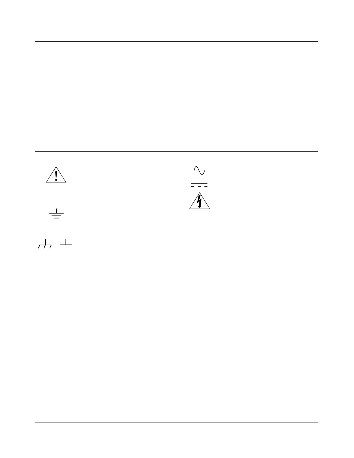
Safety Symbols
Instruction manual symbol affixed to product. Indicat es that the user must refe r t o the
manual for specific WARNING or CAUTION information to avoid personal injury
or damage to the product.
Indicates the field wiring terminal that must
be connected to earth ground before operating the equipment—protects against electrical shock in case of fault.
Frame or chassis ground termi nal — t ypi-
or
cally connects to the equipment’s metal
frame.
WARNING
CAUTION
Alternating current (AC).
Direct curren t (DC).
Indicate s ha za rdous voltage s.
Calls at te nt i on t o a pr ocedure, practi ce, or
condition that could cause bodily injury or
death.
Calls at te nt i on t o a pr ocedure, practi ce, or condition that could possibly cause damage to
equipme nt or perma nen t los s of data.
WARNINGS
The following ge ner al safet y prec aut ions mu s t be observed du ri ng al l phas es of oper ation, service, and re pai r of this pr oduct .
Failure to comply with these prec aut ions or with specific war nings elsewhe re in this manual violates safety stand ard s of design ,
manufacture, and intended use of the product. H ewl ett-Packard Company assumes no liability for the customer’s failu re to
comply with these requirements.
Ground the equipment: For Safety Cl as s 1 equipmen t (equ ipment ha vin g a protective ea rth ter mi nal) , an unint erru ptib le sa fety earth
ground must be provide d from the ma in s power sour ce to the produ ct input wi rin g termi nals or suppli ed power cable .
DO NOT operate the produc t in an explosive at mospher e or in the presen ce of flammable gases or fumes.
For continued protect ion a gainst fire, repl ace the li ne fuse(s) only with fuse(s) of the same voltage and current rating and type .
DO NOT use repaired fuses or short-circui ted fuse holders.
Keep away from live circuits: Operatin g personnel must not remove equipment covers or shields. Procedures involving the removal
of covers or shields are for use by service-trained personn el onl y. Under certain conditions , dangerous voltages m ay exist even with the
equipment switched off. To avoid dangerous ele ctrical shock , DO NOT perf orm procedures involving cover or shield removal unless
you are qualified to do so.
DO NOT operate damaged equipment: Whenever it is possible that the safety protection features built into this pr oduct have been impaired, either t hr ough physical dama ge, excessive moisture, or an y ot her re as on, REMOVE POWER and do not use the product until
safe operation can be verified by service-trained personnel. If necessar y, return the produ ct to a Hewlett -Packar d Sa les and Se rvice O ffice for service and repair to ensure that safety features are maintained.
DO NOT service or adjust alon e: Do not attempt internal service or adjustment unless another person, capable of rendering first aid
and resuscitation, is present.
DO NOT substitute par ts or modify equipme nt: Because of the danger of introducing additional hazards, do not install substitute
parts or perform any unauth orized modifica tion to the product. Ret urn the produ ct to a Hewlett -Packar d Sa les and Ser vice O ffice for
service and repair to ensure that safety features a re ma i nt ai ned.
8 HP E1418A User’s Manual
Artisan Technology Group - Quality Instrumentation ... Guaranteed | (888) 88-SOURCE | www.artisantg.com
Page 10

Declaration of Conformity
according to ISO/IEC Guide 22 and EN 45014
Manufacturer’s Name: Hewlett-Pa ckar d C ompany
Loveland Manufacturing Center
Manufact ure r’s Addre s s: 815 14th Street S.W.
Loveland, Colorado 80537
declares, that the product:
Product Name: 8/16-Ch an nel D/A Con ver ter Modul e
Model Number : HP E1 418A
Produc t Opt ion s: All
conforms to the following Pr od uct Spe cifi cati ons :
Safety: IEC 1010-1 (1990) Incl . Amend 1 (1992) /E N610 10-1 (1993)
CSA C22.2 #1010.1 (1 992)
UL 3111
EMC: CISPR 11:1990/EN55011 (1991): Group 1 Class A
IEC 801-2:1991/ E N5008 2-1 (1 992) : 4 kVCD, 8 kVAD
IEC 801-3:1984/ E N5008 2-1 (1 992) : 3 V/m
IEC 801-4:1988/ E N5008 2-1 (1 992) : 1 kV Power Line
.5 kV Signal Lin es
Supplementary Information: The product herewith c omplies wit h th e requirements of the Low Voltage
Directive 73/23/EEC and the EMC Directive 89/336/ EEC (inclu sive 93/68/E EC) and carr ies the "CE" mark ing
accordingly.
Tested in a typical HP C-Si ze VXI Ma infr ame configuration .
November 6, 1995 Jim White, QA Manager
European c ontact : Your loca l He wlett-Pa cka rd Sa les and Ser vi ce O ffic e or Hewlett- Packa rd GmbH,
Department HQ- TRE, Herrenberg er Stra ße 130, D-71034 Böblingen, German y (FAX +4 9-7031-14-3143).
HP E1418A User’s Man ual 9
Artisan Technology Group - Quality Instrumentation ... Guaranteed | (888) 88-SOURCE | www.artisantg.com
Page 11

Notes
10 HP E1418A User’s Manual
Artisan Technology Group - Quality Instrumentation ... Guaranteed | (888) 88-SOURCE | www.artisantg.com
Page 12
Please fold and tape for mailing
Reader Comment Sheet
HP E1418A User’s Manual
Editio n 2
You can help us improve our manual s b y sharing your commen ts and sug gesti ons. In apprec iat i on of your time, we will
enter yo u in a quarterly drawing for a Hewle tt -Pac kar d Palmt op Per s onal C omputer (U.S. government employees
cannot par ticipate in the drawing).
Your Name
C ompany N a me
Job Title
Address
Please list the s ystem c ontroller, opera ting system, programmi ng lan gua ge, and plug-in modules you are using.
City, State/Province
Country
Zip/Postal C ode
Telephone Number with Area Code
fold here
BUSINESS REPLY MAIL
FIRST CLASS PERMIT NO. 37 LOVELAND,CO
HEWLETT-PACKARD COMPANY
cut along this line
Measurement Systems Division
Learning Products Department
P.O. Box 301
Loveland, CO 80539-9984
NO POSTAGE
NECESSARY
IF MAILED
IN THE
UNITED STATES
fold here
Please pencil- in on e circle for each statement below: Disagree Agree
• The documentation is well organized. OOOOO
• Instructions are easy to understand. OOOOO
• The documentation is clearly written. OOOOO
• Examples are clear and useful. OOOOO
• Illustrations are clear and helpful. OOOOO
• The documentation meets my overall expectations. OOOOO
Please write any comments or suggestions below--be specific.
Artisan Technology Group - Quality Instrumentation ... Guaranteed | (888) 88-SOURCE | www.artisantg.com
Page 13

12 HP E1418A User’s Manual
Artisan Technology Group - Quality Instrumentation ... Guaranteed | (888) 88-SOURCE | www.artisantg.com
Page 14

Using This Chapter
This chapter provides general module information and tasks you must
perform to install a nd pr e pa re your module. A procedur e to verify your
installation is also given. The chapter is divided into the followin g s ections:
Chapter 1
Module Setup and In stalla tion
• Module Description . . . . . . . . . . . . . . . . . . . . . . . . . . . . . . . . Page 13
• Functional Description. . . . . . . . . . . . . . . . . . . . . . . . . . . . . . Page 16
• Fron t Pan el C onne ctors . . . . . . . . . . . . . . . . . . . . . . . . . . . . . Page 18
• Setting the Logical Address Switch. . . . . . . . . . . . . . . . . . . . Page 19
• Module Installation . . . . . . . . . . . . . . . . . . . . . . . . . . . . . . . . Page 20
• Terminal Modules . . . . . . . . . . . . . . . . . . . . . . . . . . . . . . . . . Page 22
• Wiring the Terminal Modu le. . . . . . . . . . . . . . . . . . . . . . . . . Page 23
• Atta ching t he Ter minal Module. . . . . . . . . . . . . . . . . . . . . . . Page 2 5
• Removin g the Terminal Mo dule . . . . . . . . . . . . . . . . . . . . . . Page 26
• Terminal Module Options . . . . . . . . . . . . . . . . . . . . . . . . . . . Page 27
• Terminal Modul e Connect ors . . . . . . . . . . . . . . . . . . . . . . . . Page 30
• Configuring the Terminal Module. . . . . . . . . . . . . . . . . . . . . Page 31
• Terminal Modul e Connect ions . . . . . . . . . . . . . . . . . . . . . . . Page 33
• Initial Operation . . . . . . . . . . . . . . . . . . . . . . . . . . . . . . . . . . . Page 37
Module Description
The HP E1418A is an 8 or 16 channel digital- t o-ana log converter module
for use in a VXIbus C-s ize mainframe. The modu le is a regis ter-based
device. The module can be programmed via direct register access or, with
the appropriat e driver , by high level commands. This manual de scribes
programming the module using SCPI (Standard Commands for
Programmable Instruments) a nd the SCPI driver.
Each HP E1418A module is a unique instrument having its own output
buffer and error queu e. Multiple modules cannot be combined into a single
instrument.
Each channel can be configured to eith er voltage or current output mo de.
When configu r ed f or voltage output, voltages in the range of -16.0 to
+16.0 Volts can be set. When configured f or current output, current in the
range of -0.02 to + 0.02 Amps can b e s et. The c hannel output mode can be
programmatically set, or, can be forced to either voltage or current by
mechanical jumpers on the terminal module.
Chapter 1 Module Setup and Insta ll ation 13
Artisan Technology Group - Quality Instrumentation ... Guaranteed | (888) 88-SOURCE | www.artisantg.com
Page 15
Each output channel is individually configurable to be either an isolated
output or a non-isolated output. Cha nne l configuration to is olated or
non-isolat ed is made by individual plu g- on modules for each channel.
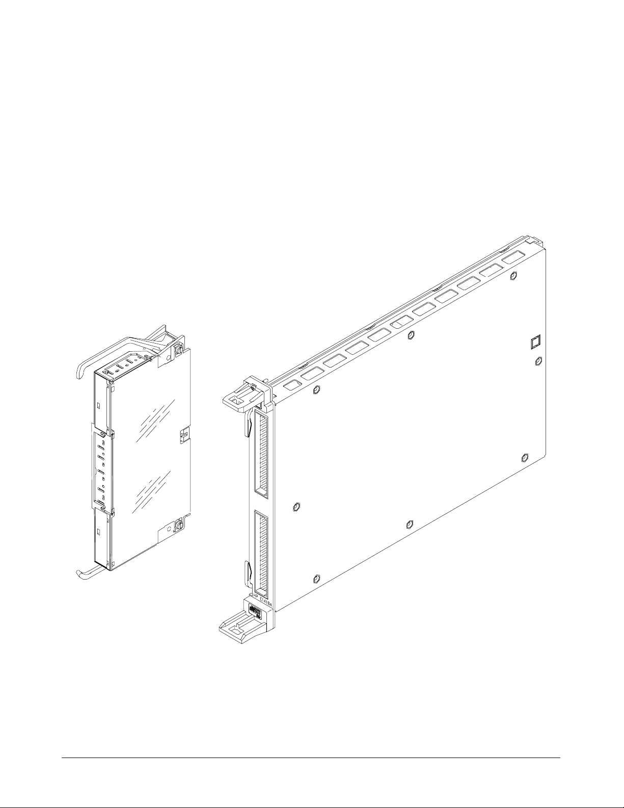
Figure 1-1 shows the module.
Figure 1-1. T h e HP E1418A 8/16-Channel D/A Converter
with Terminal Module
14 Module Setup and Instal lation Chapter 1
Artisan Technology Group - Quality Instrumentation ... Guaranteed | (888) 88-SOURCE | www.artisantg.com
Page 16

Ordering Opti ons The HP E1418A may be ordered from Hewlett-Pa c kard in a va r iety of
configurations. As ordered, the module has t he following options:
Description
HP E1418A 8-Channel D/A Converter with Non-Isolated Outpu ts
HP E1418A Option 001 16-Channel D/A Converter with Non-Isolated Outp uts
HP E1418A Option 002 8-Channel D/A Converter with Isolated Outpu ts
HP E1418A Option 003 16-Channel D/A Converter with Isolated Output s
Field Kits The module can also be us er configured as described beginning on page 166
of this manual. The following field expansion and configuration kits are
available:
Description Use
HP E1523A Single Channel Isolated
plug-on modul e
HP E1524A Expansion kit, 8-Channel
Non-Isolated Out put s
HP E1525A Expansion kit, 8-Channel
Isolated Out pu t s
To change a single channel from
non-isolated to isolated ou tput.
To add 8 additional non-isolated
channels to an existing 8- cha n nel
module .
To add 8 addit io nal isol at e d cha n n els to
an existing 8-cha n n el modul e.
Terminal Modules The standard HP E1418A Terminal Module provides screw terminals for
connections. Two other terminal options are available with the HP E1418A:
– Crimp an d Ins er t ( O ptio n A3E )
– Ribbon Cable (Option A3H)
– Terminal Module Housing wit hout a terminal module PC board or
connectors included (Option 135)
Chapter 1 Module Setup and Insta ll ation 15
Artisan Technology Group - Quality Instrumentation ... Guaranteed | (888) 88-SOURCE | www.artisantg.com
Page 17
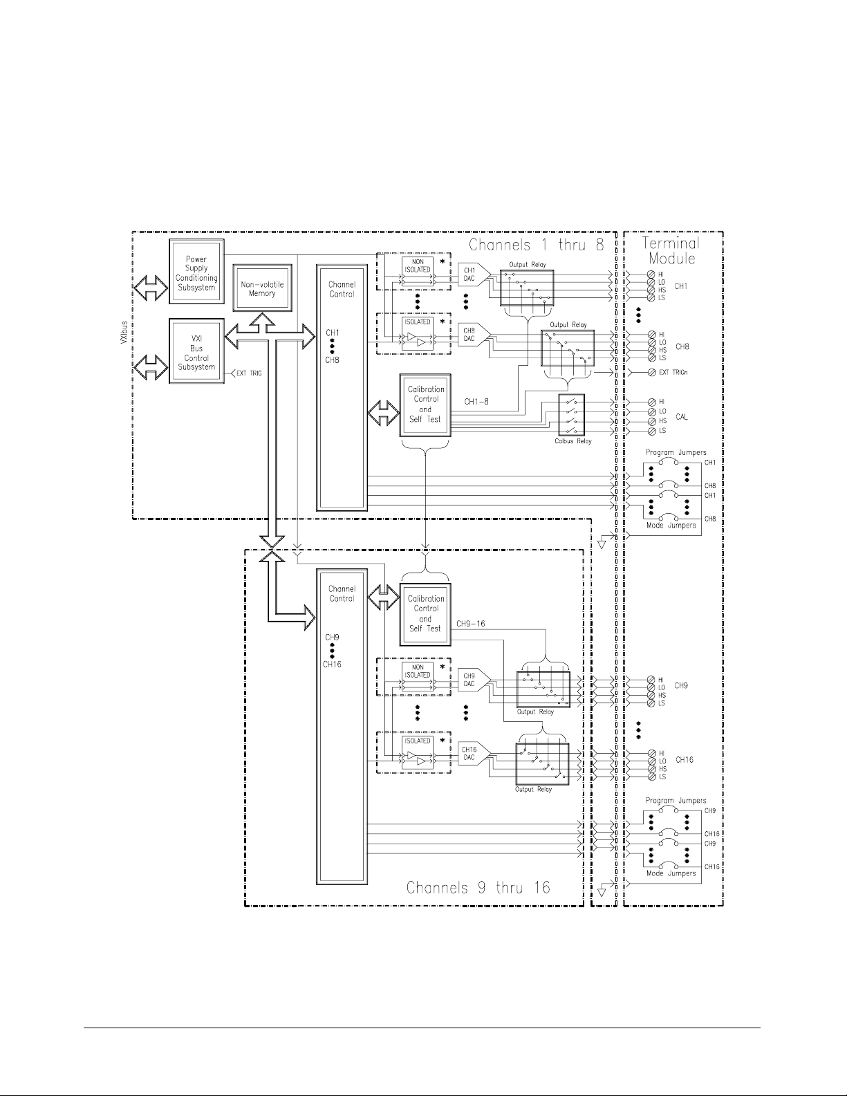
Functional Description
The HP E1418A provides great flexibility in configuration. This functional
description will help you become famil iar with the various configurations
and how th e module is structured. A functio nal bloc k diagra m is shown in
Figure 1-2.
Figure 1-2. A Function al Blo ck Diag ra m
Each channel MUST have either an isolated or non-isolated plug-on module installed. Channels may be configured
*
using any combination of Isola ted and Non -Isol ated plug-on modules.
16 Module Setup and Instal lation Chapter 1
Artisan Technology Group - Quality Instrumentation ... Guaranteed | (888) 88-SOURCE | www.artisantg.com
Page 18

As shown, there are four major assemblies that m a k e up an HP E1418A:
– Channels 1 through 8 main board and VXIbus backplane circuitry.
– Channels 9 through 16 expansion board.
– Isolated or Non- isola ted plug-on modules.
– Terminal Module.
Cha nnels 1–8 m ain board and VXIbus backplane circuitry.
This assembly contains all the VXIbus interface and decoding circuitry.
Isolated and Non-Isolated plug-on modules f or channels 1–8 connect to this
assembly. The panel connectors for the terminal module are also mounte d
on this assemb ly.
The optional C hannels 9–16 expansion board is electrically connected and
mechanically mounted to the main board. I s olated and Non-Isolated
plug-on modules for channels 9–16 connect to this assembly.
Isolated or Non-isolated plug-on modules are required for every channel.
Eight plug-on modules mount to the main board and 8 plug-on modules
mount to the expansion board. Any c omb inati on of is olated or non-isolated
plug-on modules may be used, but every channel must ha ve a plug-on
module ins ta lle d.
The Terminal Module shown i n Figure 1-2 is the standard screw-type
terminal module. This module provides screw connections for each channel
output, the calibration connections, and the external trigger in connections.
This module also contains two jumpers for each channel; one, called the P/J
Jumper, to enable or disable VXIbu s programming of the channel mode
(either voltage or current) and one, called the V/I Jumper, to set the channel
mode when the P/J Jumper is in the Jumper position.
Chapter 1 Module Setup and Insta ll ation 17
Artisan Technology Group - Quality Instrumentation ... Guaranteed | (888) 88-SOURCE | www.artisantg.com
Page 19
Front Panel Connectors
Figure 1-3 shows the connections at the front panel connectors of the main
module.
Figure 1-3. HP E1418A Front Panel Connector Pinout
18 Module Setup and Instal lation Chapter 1
Artisan Technology Group - Quality Instrumentation ... Guaranteed | (888) 88-SOURCE | www.artisantg.com
Page 20
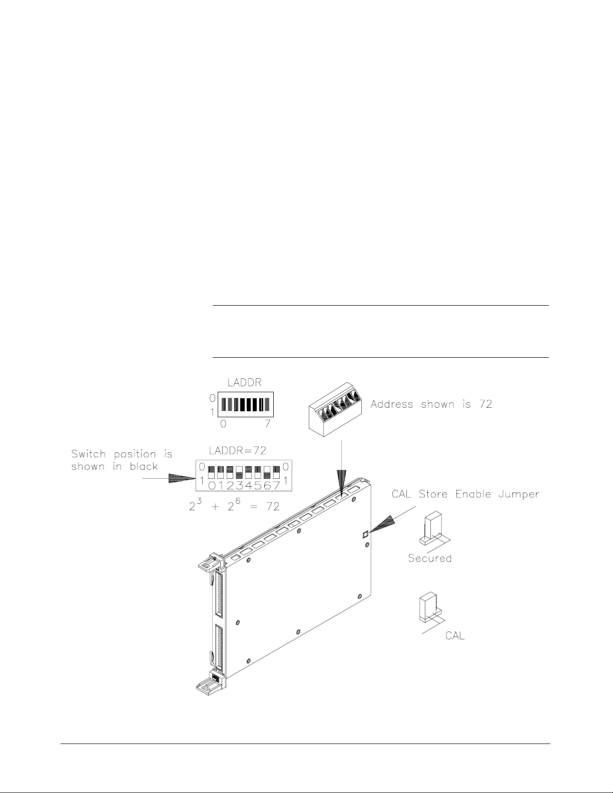
Setting the Logical Address Switch
Figure 1-4 shows the logical address switch location and setting. The logical
address switch factory setting is 72. Valid addresses range from 1 to 255.
When used with an HP Command Module the fac t ory set address of
decimal 72 results in a module address of 9 (72 divided by 8). The module
address is used as a secondary address when using HP-IB and a Command
Module. For ex ample, the module address may be 7 09 09, wher e 7 is the
HP-IB interfac e address, 09 is the command module addr ess, and 09 is the
HP E1418A addre ss.
The HP E1418A supports dynamic address configuratio n. When you set the
logical address to 255, the res o ur ce manager s ets the logical address
programmatically.
Note When using an HP C-size mainframe with the HP E1405/E1406 Command
Modules, the logical address setting must be a multipl e of 8.
Figure 1-4. Setting the Logical Address
Chapter 1 Module Setup and Insta ll ation 19
Artisan Technology Group - Quality Instrumentation ... Guaranteed | (888) 88-SOURCE | www.artisantg.com
Page 21
Module Installation
To install t he module:
1. Verify the position of the CAL Store Enable Jumper for your
application. The Jumper, as shipped, is in the CAL position. In this
position, a calibration may be performed and the results stored in
non-volatil e memory. In the Secured positio n, a calibration may be
performed , but may NOT be stored in no n- volat ile memory. This
jumper is described in more detail on page 156.
2. Verify or set the logical address switch as shown in Figure 1-4.
3. Install the module in a mainframe as shown in Figure 1-5.
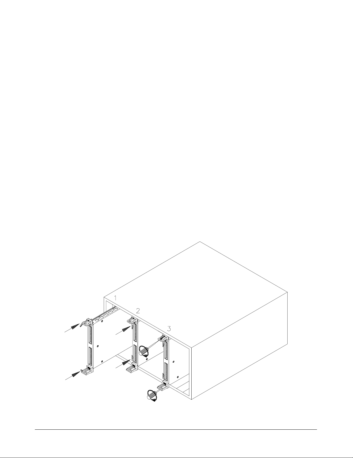
Installation in a
Mainframe
The HP E1418A may be installed in any slot (except slot 0) in a C-size
VXIbus mainframe. To install in a mainframe:
1. Set the extraction levers out. Slide t he module into an y s lot ( ex cept
slot 0) until the backplane connectors touch.
2. Seat the mo dule by moving the levers toward each other.
3. Tighten the top and bottom screws to secure the modu le in the
mainframe.
Figure 1-5. Installing the HP E1418A in a VXIbus Mainframe
20 Module Setup and Instal lation Chapter 1
Artisan Technology Group - Quality Instrumentation ... Guaranteed | (888) 88-SOURCE | www.artisantg.com
Page 22

To Remove a Module: To remove a module from a mainframe:
1. Remove any terminal modules.
2. Loosen the top and bottom screws securing the module in the
mainframe.
3. Move the extraction levers away from each other. As the levers are
moved, the module will detach from t he ba ck plane connectors.
4. Slide the module out.
Note The extraction levers will not seat and unseat the backplane connectors on
older HP VXIbus mainframes and n on-HP ma inframes . You must
manually seat the connectors by pushing the module into the mainframe
until the front panel is flush with the front of the mainframe. The extraction
levers may be used to guide or remove the module.
Chapter 1 Module Setup and Insta ll ation 21
Artisan Technology Group - Quality Instrumentation ... Guaranteed | (888) 88-SOURCE | www.artisantg.com
Page 23
Terminal Modules
Four terminal modules are available for the HP E1418A; a screw- type, a
crimp-and-insert type, a ribbon cable type, and an empty terminal housing
(without a PC board or connectors).
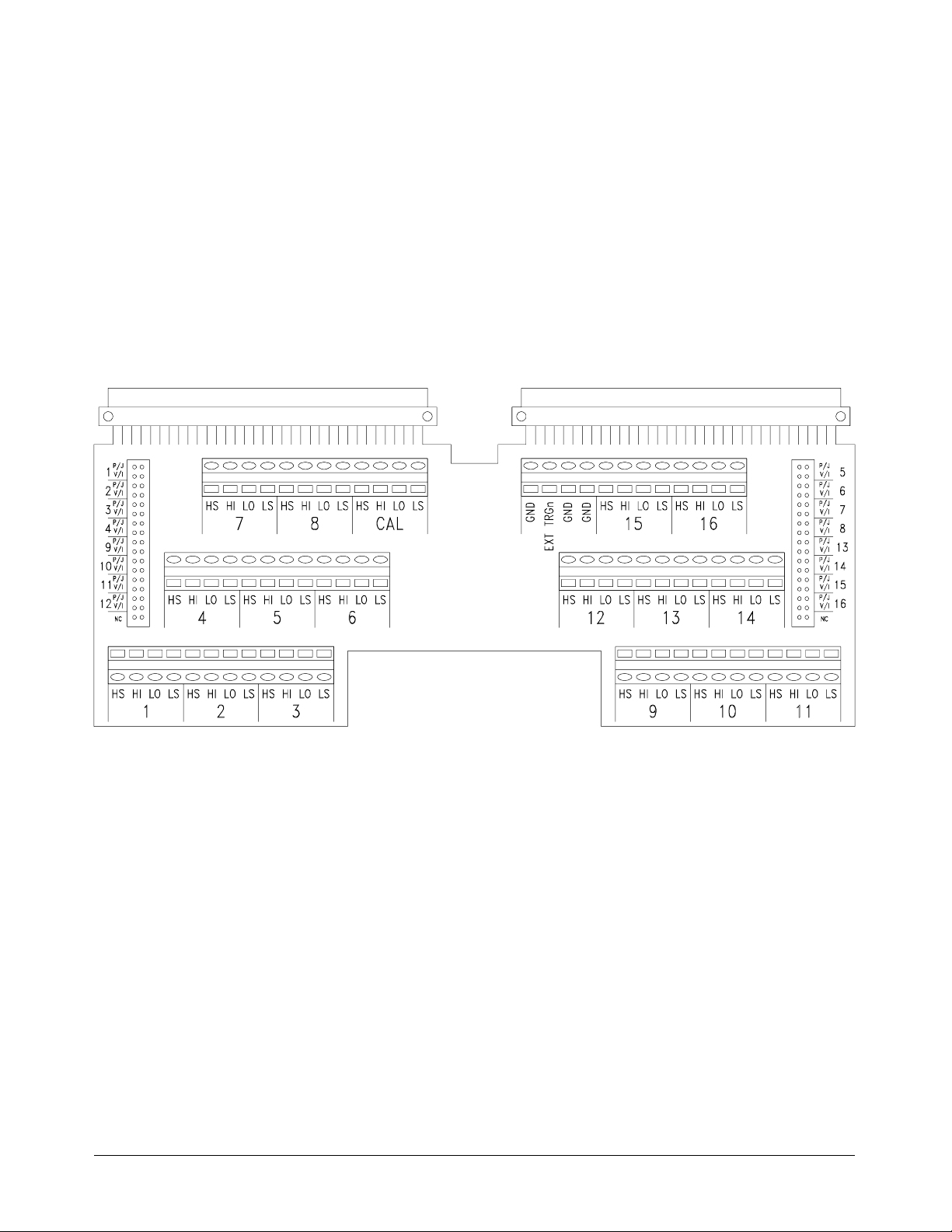
Screw-Type
Terminal Module
(Standard)
The standard terminal module uses screw-type terminals to make
connectio ns. Figure 1-6 may be photocop ied a nd used for wiring layout .
Figure 1-6. Screw-Type Termin al Modu le Layou t
22 Module Setup and Instal lation Chapter 1
Artisan Technology Group - Quality Instrumentation ... Guaranteed | (888) 88-SOURCE | www.artisantg.com
Page 24
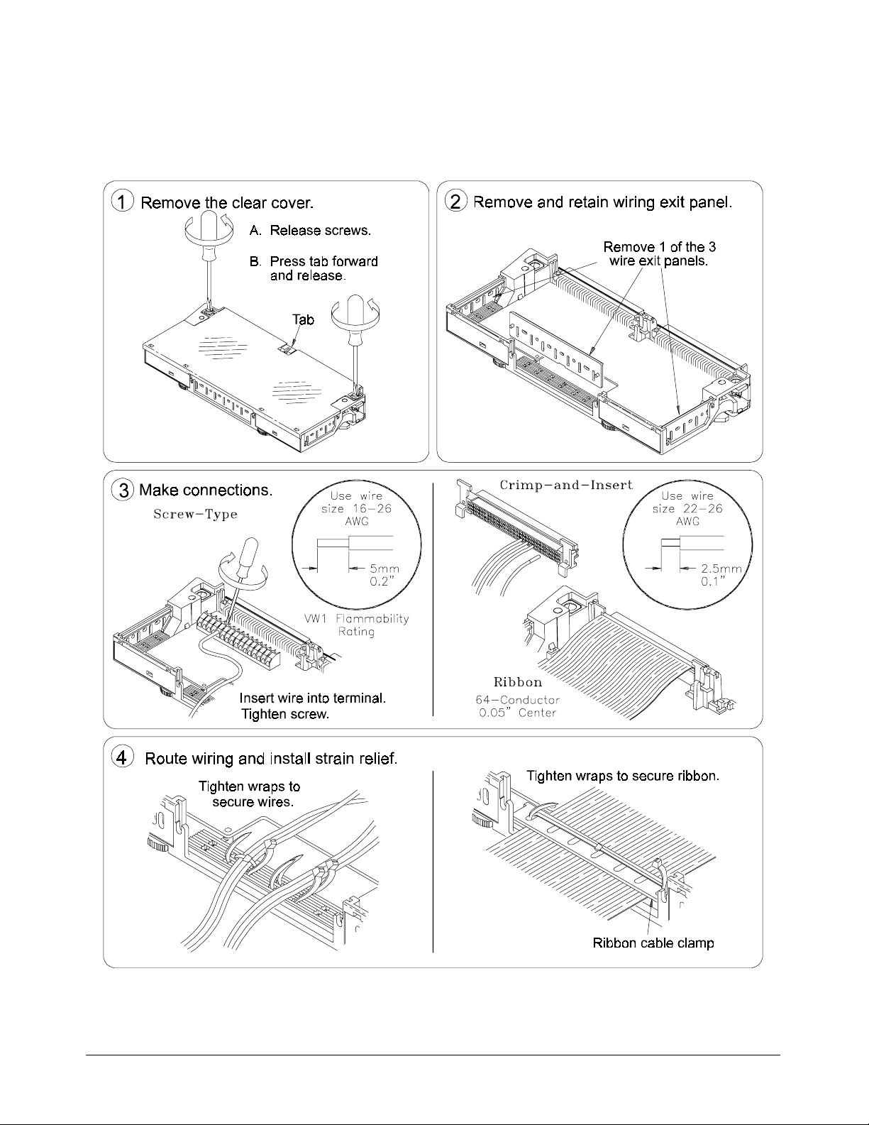
Wiring the Terminal Module
Figure 1-7 shows how to open and wire the HP E1418A terminal module.
Figure 1-7. Wiring the HP E1418A Terminal Module
(
continued on next page)
Chapter 1 Module Setup and Insta ll ation 23
Artisan Technology Group - Quality Instrumentation ... Guaranteed | (888) 88-SOURCE | www.artisantg.com
Page 25
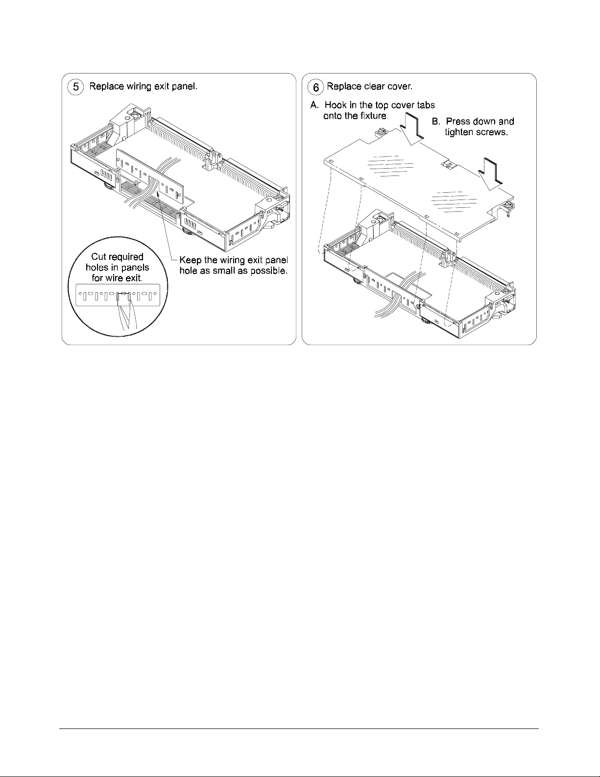
Figure 1-7. Wiring the HP E1418A Terminal Module
(
continued from previous page)
24 Module Setup and Instal lation Chapter 1
Artisan Technology Group - Quality Instrumentation ... Guaranteed | (888) 88-SOURCE | www.artisantg.com
Page 26
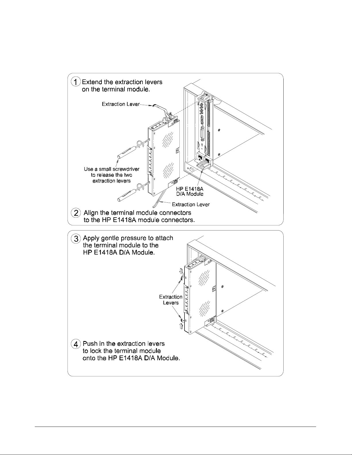
Attaching the Terminal Module
Figure 1-8 shows how to attach the HP E1418A terminal module.
Figure 1-8. Attaching the HP E1418A Terminal Module
Chapter 1 Module Setup and Insta ll ation 25
Artisan Technology Group - Quality Instrumentation ... Guaranteed | (888) 88-SOURCE | www.artisantg.com
Page 27
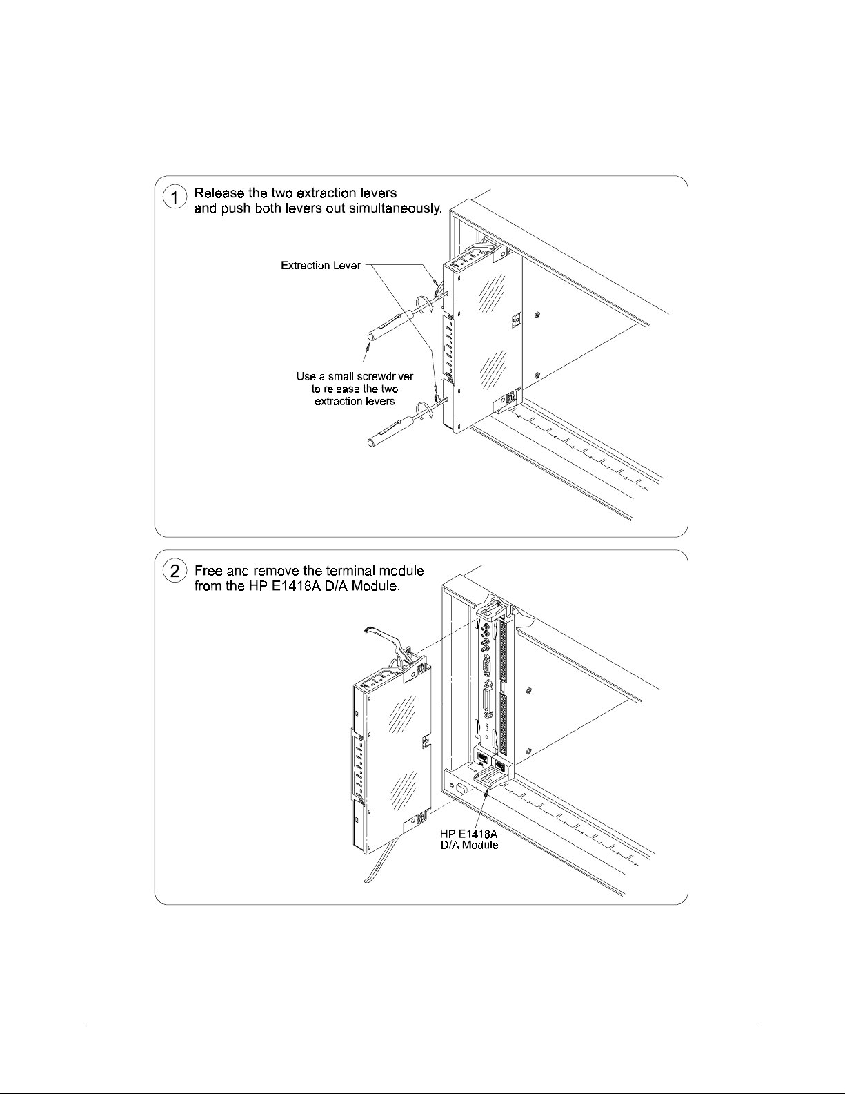
Removing the Terminal Module
Figure 1-9 shows ho w to remove the HP E1418A terminal module.
Figure 1-9. Removing the HP E1418A Termi nal Module
26 Module Setup and Instal lation Chapter 1
Artisan Technology Group - Quality Instrumentation ... Guaranteed | (888) 88-SOURCE | www.artisantg.com
Page 28
Terminal Module Options
Besides the standard screw-type terminal module, the HP E1418A can be
ordered with the following two optio ns. One option (A3E) provides
crimp-and-insert connectors and terminal housing. The other option (A3H)
provides a ribbon cable con nector and termina l hous ing.
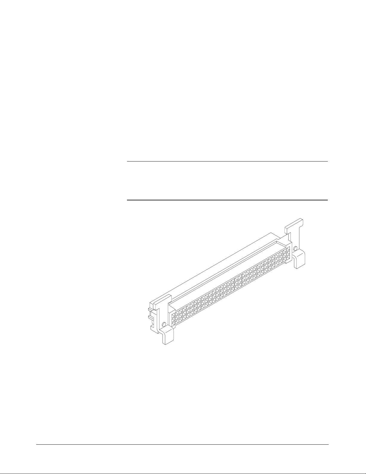
Option A3E HP E1418A Option A3E can be ordered if a crimp-an d -insert terminal
module is desired. This allows you to crimp connectors onto wires which
are then inserted directly into the HP E1418A faceplate connector. Ref er to
the pin-out diagram on page 30 to make the connections. The
crimp-and-insert connector is shown in Figure 1-10.
Note The pin numbering on th e crimp-and-insert conn ector may not agree with the
pin nu mberi ng on the HP E1418’s fa ceplate connector. Use the pin
numbering on the faceplate connector to wire the crimp-and-insert connector.
Figure 1-10. Option A3E Crimp- and-I nsert Con necto r
Chapter 1 Module Setup and Insta ll ation 27
Artisan Technology Group - Quality Instrumentation ... Guaranteed | (888) 88-SOURCE | www.artisantg.com
Page 29
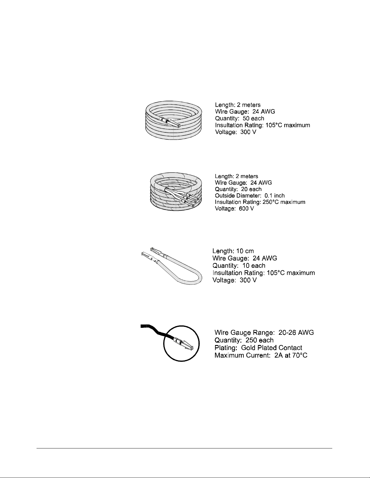
Crimp-and-Insert
Terminal Module
Accessories
The following accessories are necessary f or use with crimp-and-insert
Option A3E:
Single-Conductor and
Contact
Shielded-Twisted-Pair and
Contacts
A crimp-and-insert contact is crimped onto o ne end of a wire. The other
end is not t erminated. Order HP 91510A.
A crimp-and-insert contact is cr im ped onto each conductor at one e nd of a
shi elded- t wist ed -pair cable. The other end is not terminated. Order
HP 91511A.
Jumper Wire and Contacts A crimp-and-insert contact is crimped onto each end of a single-conductor
ju mper wire. This jump er is typica l ly used to tie t wo p i n s togethe r in a
single crimp-and-insert connector. Order HP 91512A.
Crimp-and-Insert Co ntacts These co ntacts ma y be crimped onto a conductor and then ins erted into a
crimp-and-insert connector. The crimp too l kit is required to crimp the
contacts ont o a conductor and remove the contact from the connector.
Order HP 91515A.
Crimp-and-Insert Tools The hand crimp tool (part number HP 91518A) is used for crimping
contacts ont o a conductor. The pin extractor to ol (pa rt number HP 91519A)
is required f or removing contacts from the crimp-a nd-insert connector.
These products are not included with Option A3E or with the terminal
option accessories listed earlier.
28 Module Setup and Instal lation Chapter 1
Artisan Technology Group - Quality Instrumentation ... Guaranteed | (888) 88-SOURCE | www.artisantg.com
Page 30
Extra Crimp-and-Insert
Connectors
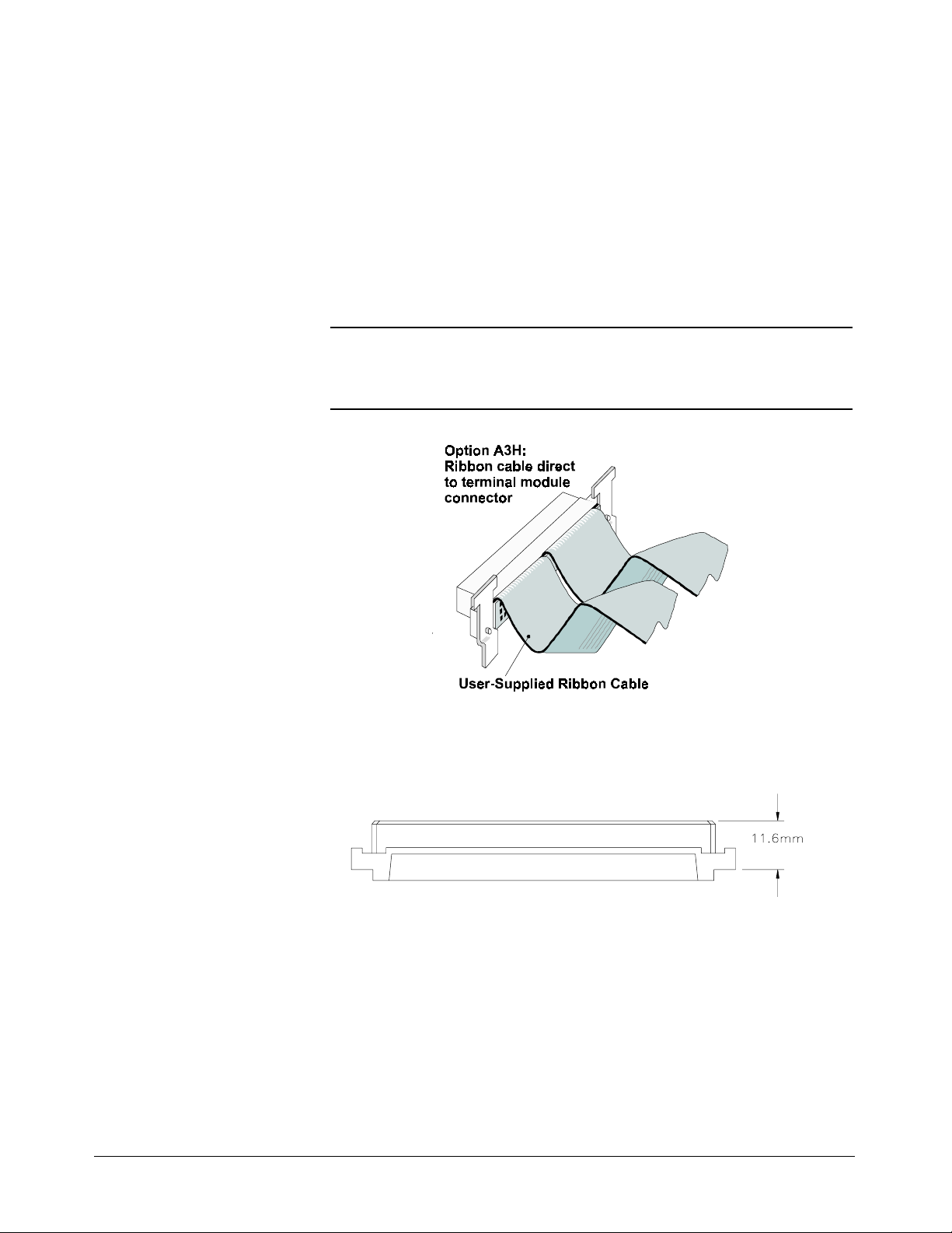
Option A3H The Ribb on Cable Connector Terminal Option provides a terminal housing
Note In Figure 1-12, t he center row of each connector is not u s ed in t he ribbon
The crimp-and-insert connector is normally supplied with Option A3E.
Contact H ewl ett-Pa c kard if addit ional connectors are need ed.
Order HP 91484B.
and ribbon cabl e connectors. The connectors ar e designed to be used with
64-pin 0.05 inch center ribbon cables (not provided). Us e Figure 1-12 to
make the connections.
cable. The center row of both connectors is module ground (GND).
Figure 1-11. Option A3H Ribbon Cable Con nect or
Option 135 The Terminal Module H ousing Option provides a termina l housing with no
connectors of any type.
The user-supplied connector must be a DIN 41612 type C female,
11.6 mm dime ns ion as shown above.
Chapter 1 Module Setup and Insta ll ation 29
Artisan Technology Group - Quality Instrumentation ... Guaranteed | (888) 88-SOURCE | www.artisantg.com
Page 31

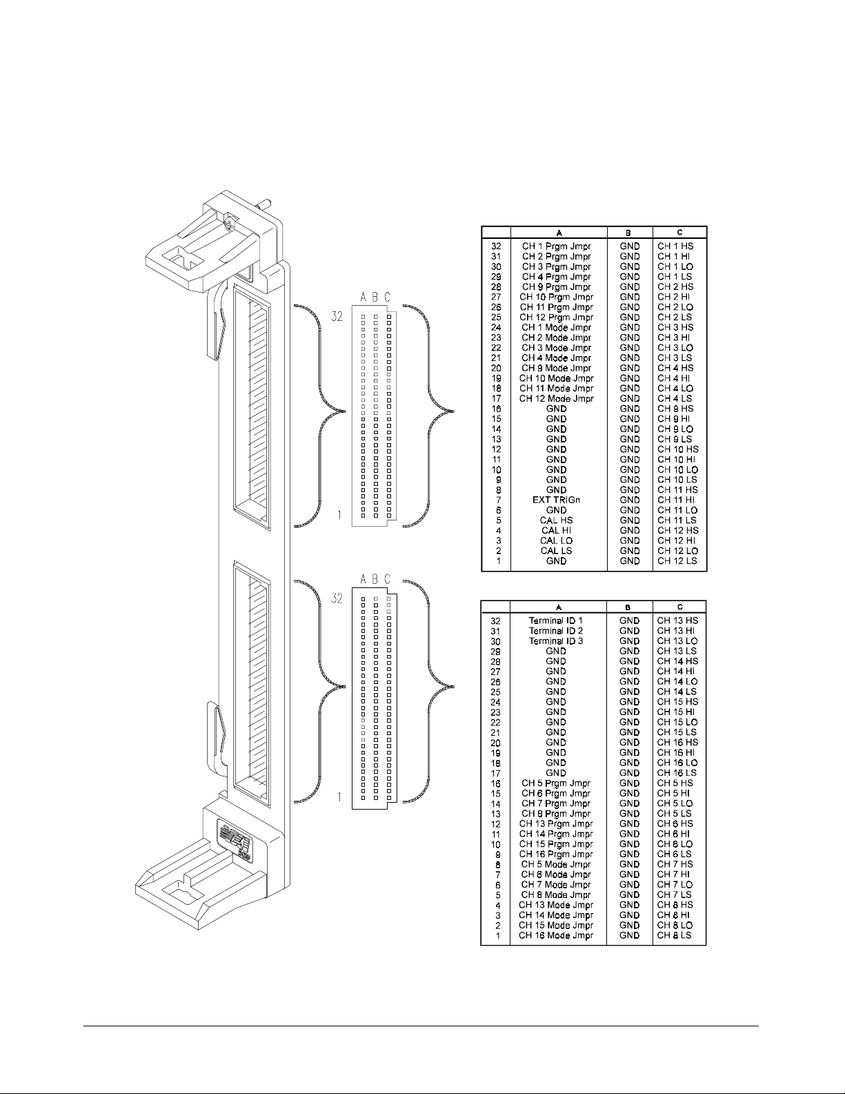
Terminal Module Connectors
Figure 1-12 s hows the connections at the terminal module connectors.
Figure 1-12. HP E1418A Terminal Module Connector Pinout
30 Module Setup and Instal lation Chapter 1
Artisan Technology Group - Quality Instrumentation ... Guaranteed | (888) 88-SOURCE | www.artisantg.com
Page 32

Configuring the Terminal Module
The screw-type terminal mod u le contains jumpers that control how the
HP E1418A operates. The jumpers are shipped in a separate bag with the
terminal module. The HP E1418A will operate without any jumpers
installed. You can, however, store the jumpers on the terminal module for
later reconfiguration. Figure 1-13 shows the jumper locations and example
settings.
There are two j u mpers for each channel; a P/J jumper and a V/I jumper.
The two j umpers work together.
Figure 1-13. P/J and V/I Jumpers
P/J Jumper The P/J jumper s ets the channel output mode to b e either Progra m
Selectable or Jumper Sel ectable. When the jumper is in the program
selectable position, the channel output mode can be s et via progra m ming
commands. In the jumper selectable position, the channel output mode is
set via the V/I jumper.
V/I Jumper The V/I jumper sets the channel output mode to either voltage or cur r ent
when the P/J jumper is set to the Jumper Sel ectable position. When the P/J
ju mper is set t o Pr o g r am Selectab l e , this j umper has no effect.
Notes With no jumpers installed, the module will be in the Program S electa b le
output mo de.
When the P/J Jumper is set to the Jumper Selectab le position, the output
mode cannot be changed with SCPI co mman ds. The output mode follo wing
*RST common command will be the mode s et by t he V/I jumper.
a
Chapter 1 Module Setup and Insta ll ation 31
Artisan Technology Group - Quality Instrumentation ... Guaranteed | (888) 88-SOURCE | www.artisantg.com
Page 33

Options A3E and A3H
Terminals
The P/J jumper connectio n for each channel is named CH X PRGM JMPR
in the conn ection diagram on page 30. W ith no connection to this pin, the
module will operate in the Program Selectable mode. Shorting this pin to
GND will set the Jumper Selectable mode for channel X.
When CH X PRGM JMPR is short ed to GND, th e CH X MODE JMPR pin
(corresponding to the V/I Jumper) sets the output mode f or channel X. If
the pin is op en, volt age output mode is s elec ted. If the pin is shorted to
GND, current output m ode is selec t ed for channel X.
32 Module Setup and Instal lation Chapter 1
Artisan Technology Group - Quality Instrumentation ... Guaranteed | (888) 88-SOURCE | www.artisantg.com
Page 34

Terminal Module Connections
Each channel has four output l ines; HI, LO, HS (Hi Sense), and LS (Low
Sense). Wh en using a c hannel in the voltage output mo de, you can use t he
sense lines to increase accuracy or to compensate f or long lead lengths. The
sense leads ar e not used in the current output mode.
Voltage and
Current Output
Connections
Note The sense leads are internally disconnected for current output. External
Figure 1-14 shows connections for three types of output. Channel 1 is
connected in t he 2-wire voltage output mode, the sense leads are not used
(and the sense connections need not be made). Channel 2 is connected in
the 4-wire v oltage output mode. Us e this connection for the hig hest volta ge
accuracy and to compensat e for long lead lengths. Channel 3 is connected
for current output m ode (sen s e is not used for current output).
wiring may be left connected to th e sense outputs on the terminal module
with no effect.
Figure 1-14. Typical Output Connecti o ns
Options A3E and A3H
HI, HS, LO, a nd LS connections are shown on the diagram on pa ge 30.
Terminals
Chapter 1 Module Setup and Insta ll ation 33
Artisan Technology Group - Quality Instrumentation ... Guaranteed | (888) 88-SOURCE | www.artisantg.com
Page 35

Combining
Channels
You can combine channels in s eries t o obt a in higher output vo ltage s or in
parallel to obtain higher output cur r ents.
Channels in Series • All channels conn ected in series MUS T be configured as isolated
channels ( with isolated plug-on modules installed).
• Up to 3 c hannels may be c ombined, but the output volta g e MUST
NOT exceed 42 Vdc/42 Vpeak.
Channels in Parallel • Channels may be either Isolated or Non-Isolated.
• Up to 16 channels may be combined.
Figure 1-15 s hows h ow to c ombine volt age channels (in series) and current
channels (in para llel).
CAUTIONS All SERIES CONNECTED o utp ut channels MUST be configure d as
ISOLATED O U T PUTS.
When combin i ng output v olt ag e chan nels, be s ure not to exc e ed the
maximum module isolation rating of 42 Vdc or 42 Vpeak.
Figure 1-15. Combined Chann els Outpu t Connecti ons
34 Module Setup and Instal lation Chapter 1
Artisan Technology Group - Quality Instrumentation ... Guaranteed | (888) 88-SOURCE | www.artisantg.com
Page 36

Connecting an
External Trigger
Source
An external trigger input is provided on the terminal module. Use the
external trigger to externally synchronize multiple outputs or multiple
instruments. The External Trigger us es TTL levels. The trigger occurs
when the EXT TRIGn connection is pulled low for at least 1 µS. T ypical
connections to th e external trigger is shown in Figure 1-16.
Options A3E and A3H
Terminals
Figure 1-16. External Trigger Con necti ons
The external tri gger l ine is loca ted on the upper conn ector and is lab eled
EXT TRIGn in the diagram on page 30.
Chapter 1 Module Setup and Insta ll ation 35
Artisan Technology Group - Quality Instrumentation ... Guaranteed | (888) 88-SOURCE | www.artisantg.com
Page 37

Usi ng the CAL
Output Terminals
The CAL Output Terminals provide one set of connections that can be used
to calibrate the output on all 16 channels. Calibration and adjustment
procedures are described in Appendix D beginning on pa g e 154.
The CAL out put terminals ar e ava ila ble on the terminal module. There ar e
four lines; HI, LO, HS (Hi Sense), an d LS (Low Sense). Typical CAL
output t erminal connections are shown in Figure 1-17.
Options A3E and A3H
Terminals
Figure 1-17. Calbus Connect ions
The CAL Output Terminals are located on the upper connector and are labeled
CAL HI, CAL HS, CAL LO, and CAL LS in the diagram on page 30.
36 Module Setup and Instal lation Chapter 1
Artisan Technology Group - Quality Instrumentation ... Guaranteed | (888) 88-SOURCE | www.artisantg.com
Page 38

Initial Operation
Note This discussion applies to SCPI programming using the driv er provided
Device Driver The HP E1418A module is shipped a driver CD. This CD contains the SCPI
This section provides a programming example to help verify correct module
installation and operation. Additional programming exa mpl es and procedures
are given in the next chapter.
The examples shown here use HP BASIC and SCPI (Standard Commands for
Programmable Instruments). The example assumes a f ac tory set logical
address of 72 for the HP E1418A module and uses an HP Command Modul e
for co mmand interpretation. Examples in A NSI C are given in the next chapter.
with the module. The SCPI commands are described in Chapter 3 of this
manual. Appendix B of this manual describes direct register access.
instrument driver, VXIplug&play drivers, example programs, and HP VIC
(VXI Installation Consultant). Follow the instructions contai ned on the CD to
properly install the device driver.
The following example shows how to query the command module and
verify that the correct device driver is installed:
10 DIM A$[256]
20 OUTPUT 70900;"DIAG:DRIV:LIST?"
30 ENTER 70900;A$
40 PRINT A$
50 END
In this exam ple, the co mmand modu le is loca ted on H P- IB ( inter face a ddr es s 7)
and uses a primary address of 09. Responses to this example vary depending
upon the drivers loaded on your system. A typical response might look like:
E1418,E1418,A.01.00,RAM;SWITCH,SWITCHBOX,A.08.00,RAM;
SYSTEM,E1405A,A.08.00,ROM;IBASIC,IBASIC,A.04.02,ROM;
VOLTMTR,E1326A,A.05.00,ROM;SWITCH,SWITCHBOX,A.07.00,
ROM;COUNTER,E1332A,A.04.02,ROM;COUNTER,E1333A,A.04.02,
ROM;DIG_I/O,E1330A,A.04.03,ROM;D/A,E1328A,A.04.02,ROM
Verify that the string “E1418,E1418,A.01.00,” is loca ted somewhere
within the returned string.
Chapter 1 Module Setup and Insta ll ation 37
Artisan Technology Group - Quality Instrumentation ... Guaranteed | (888) 88-SOURCE | www.artisantg.com
Page 39

Module
Identification
This example can be used to verify that the logical addr e ss ha s been
correctly set, that the module is corr e c t ly installe d, and that the module is
communicat ing with the command module . The terminal module do es not
need to be instal led for t h is example to work. This example qu eries t he
module for the identific ation st ring.
10 DIM A$[256]
20 OUTPUT 70909;"*IDN?"
30 ENTER 70909;A$
40 PRINT A$
50 END
The response should be similar to one of the fo llowing:
HEWLETT-PACKARD,E1418A_8CH,xxxxAxxxx,A.01.00
or
HEWLETT-PACKARD,E1418A_16CH,xxxxAxxxx,A.01.00
The xxxxAxxxx port ion of the response string is the module serial number.
38 Module Setup and Instal lation Chapter 1
Artisan Technology Group - Quality Instrumentation ... Guaranteed | (888) 88-SOURCE | www.artisantg.com
Page 40

Using This Chapter
This chapter provides examples and descriptions of the mo st c ommon
operations using the HP E1418A. Use this chapter to gain an overview of how
to program the module, and to obtain programming hints. The examples
shown in this chapter are in ANSI C and use SCPI commands to control the
module. The SCPI commands are described in detail in Chapter 3 of this
manual. SCPI usag e conventions and synta x r ules are described beginning on
page 60.
This chapter is divided into the following sections:
Chapter 2
Programming Examples
• Querying Module Identification and Configuration. . . . . . . . . Page 40
• APPLy Output . . . . . . . . . . . . . . . . . . . . . . . . . . . . . . . . . . . . Pa ge 45
• Error Check ing. . . . . . . . . . . . . . . . . . . . . . . . . . . . . . . . . . . . Page 47
• SOURce Output . . . . . . . . . . . . . . . . . . . . . . . . . . . . . . . . . . . Page 50
• Setting the Output M ode . . . . . . . . . . . . . . . . . . . . . . . . . . . . Page 52
• Controlling th e Output R elay. . . . . . . . . . . . . . . . . . . . . . . . . Page 53
• Trig geri ng. . . . . . . . . . . . . . . . . . . . . . . . . . . . . . . . . . . . . . . . Pa ge 54
• Using *OP C? . . . . . . . . . . . . . . . . . . . . . . . . . . . . . . . . . . . . . Page 56
• Combining Output Cha nne ls . . . . . . . . . . . . . . . . . . . . . . . . . Page 57
Program Examples Example programs in ANSI C format are included on the driver CD
supplied with the HP E1418A. Most examp les in this chapter are included.
The examples are ASCII files wit h the *.c extension.
Note The int data type is system dependent. Thes e exa mples were developed on
a system where int is a 16-bit integer. Other systems may define int to be a
different width.
In the examples, t he HP VI S A Trans ition L ib rary is used for I/O operations
with the VXIbus. An HP command module (HP E1405/ E1406) is used and
controlled via HP-IB.
To use the HP VISA Transition Library (ab br eviated as VTL), include th e
visa.h header fil e.
#include visa.h
Chapter 2 Programming Examples 39
Artisan Technology Group - Quality Instrumentation ... Guaranteed | (888) 88-SOURCE | www.artisantg.com
Page 41

Hewlett-Packard V T L function calls and data types typically begin with the
lower cas e let ters vi. Output and enter are performed with functions na med
viPrintf and viScanf. Both these functions require a s ession (a VTL
defined I/O funct ion ) to uniquely identify the d evice being controlled. In
the examples, the session has b een name d dac.
Querying Module Identification and Configuration
This examp le will query the modu le for the identificati on string and
determine the module configuration.
The module identification is obtained using the IEEE-488 Command
!Send query to the module.
*IDN?
!Enter a string.
The string retur ne d should be similar to one of the f ollowing:
HEWLETT-PACKARD,E1418A_8CH,xxxxAxxxxx,A.01.00
or
HEWLETT-PACKARD,E1418A_16CH,xxxxAxxxxx,A.01.00
The xxxxAxxxxx portion of t he respon se string is the module seria l
number.
The module co nfiguration is obtained using the
query.
!Send query to the module.
DIAG:CONF?
DIAGnostic:CONFiguration ?
*IDN?.
!Enter six inte gers and decod e the integ ers.
40 Programming Examples Chapter 2
Artisan Technology Group - Quality Instrumentation ... Guaranteed | (888) 88-SOURCE | www.artisantg.com
Page 42

The DIAG:CONF? query returns six integers. The six integers returned
contain the module configuration and have the following meaning.
Integer
Returned Meaning
1st Expansion Board ID in the form : 0 = present, 7 = none
(expansion board contains channels 9 through 16)
2nd Terminal Modul e ID in the form
0 = screw type, 7 = none or other
3rd Isolated/Non-isolated Channel status
A bit set to 0 indicates an isolated channel
A bit set to 1 indic ates a non-isolated channel or no plug-on
module installed (DO NOT operate the module without a plug-on
module)
Bits 0 – 15 correspond to channels 1 – 16, respectively*
4th Channel Mode
A bit set to 0 indi c ates a current out put channel
A bit set to 1 indic ates a voltage output channel
Bits 0 – 15 correspond to channels 1 – 16, respectively*
5th Channel Output State
A bit set to 0 indicates the channel output relay is closed
A bit set to 1 indicates the channel output relay is open
Bits 0 – 15 correspond to channels 1 – 16, respectively*
6th Channel Mode Programmable State (P/J Jumper)
A bit set to 0 indi c ates a channel is not mode programmabl e
A bit set to 1 indi c ates a channel is mode programmable
Bits 0 – 15 correspond to channels 1 – 16, respectively*
* For 8-channe l configurations, the upper 8 bits of integers 3, 4, 5, and 6 are set to 1’s.
For example, if the f ollo wing six integers ar e returned, the module has the
configurat i on indicated.
Decimal
Integer
1st 7 No expansion board installed
2nd 7 No Terminal Module installed or
3rd -1 All channels are non-isolated.
4th -1 All channels are voltage output channels.
5th -1 All channel outputs are disabled
6th -1 All channels are output mode
Value Configuration
(Only channels 1 through 8).
unknown terminal module installed.
(all output relays are open).
programmable.
Chapter 2 Programming Examples 41
Artisan Technology Group - Quality Instrumentation ... Guaranteed | (888) 88-SOURCE | www.artisantg.com
Page 43

Configuration
Example
The following program segment demo nstrat es how to rea d the module
identification string and the configurat ion. The configuration integers are
bit manipulated using the C operator for bit shifting result = result <<1
(a one bit shift to the left).
•
•
•
/** FUNCTION PROTOTYPE S **/
void main (void);
void err_handler(ViS ession vi, ViStat u s x); /* VTL error routine */
void sys_err(ViS e ssion re source); /* Checks for SCPI programming error s */
/** GLOBAL **/
ViStatus err;
ViSession defaultRM, cmd, dac;
•
•
•
void main (void)
{
int i,num_chan,result = {0},config [6]={0};
char buf[256] = { 0 };
/*** Check the module identification ***/
err=viPrintf(dac, “*IDN?\n”); /* request id from the module */
err=viScanf(dac, “%t”, &buf ) ; /* enter string returned */
printf (“Module is identified as a %s\n”, buf); /* print the result */
/*** Get the module conf i gurati on ***/
err=viPrintf(dac, “DIAG:CONF?\n”); /* request m odul e configurat ion */
err=viScanf (dac, “%,6d”, &config); /* ret urns six integers */
/* Decode the first integer */
result=conf ig[0] ; /* Expansion board */
if (result < 7)
{
printf (“Module is a 16 channel dev ic e\n”);
num_chan = 16;
}
else
{
printf (“Module is an 8 channel device\n”);
num_chan=8;
}
42 Programming Examples Chapter 2
Artisan Technology Group - Quality Instrumentation ... Guaranteed | (888) 88-SOURCE | www.artisantg.com
Page 44

/* Decode the second integer */
result = config [1]; /* Term inal Modul e */
if (result > 0)
{
printf (“Module does NOT have a terminal module installed\n” );
}
else
{
printf (“Module has a screw-type terminal module installed\n”);
}
/* Decode the third integer */
result=conf ig[2] ; /* Isolated or non-isol ated output s */
if (num_chan < 9) result = re sult << 8; /* strip upper 8 bits */
for (i=num_chan;i>0;i – –)
{
if (result >= 0x8000)
{
printf (“Channel %d is configured for non-isolated output\n”,i);
}
else
{
printf(“Channel %d is configured for isol ated output\ n”,i);
}
result = result < < 1;
}
/* Decode the fourth integer */
result=conf ig[3] ; /* Output Mode Volt age or Current */
if (num_chan < 9) result = re sult << 8; /* strip upper 8 bits */
for (i=num_chan;i>0;i – –)
{
if (result >= 0x8000)
{
printf (“Channel %d is set to v ol tage out put mode\n”,i);
}
else
{
printf(“Channel %d is set to current output mode\n”,i);
}
result = result < < 1;
}
Chapter 2 Programming Examples 43
Artisan Technology Group - Quality Instrumentation ... Guaranteed | (888) 88-SOURCE | www.artisantg.com
Page 45

/* Decode the fifth integer */
result=conf ig[4] ; /* Channel relay open or closed */
if (num_chan < 9) result = re sult << 8; /* strip upper 8 bits */
for (i=num_chan;i>0;i – –)
{
if (result >= 0x8000)
{
printf (“Channel %d output is disabled\n”,i);
}
else
{
printf(“Channel %d output is enabled\n”,i);
}
result = result < < 1;
}
/* Decode the sixth integer */
result=conf ig[5] ; /* P/J Jumper p osition */
if (num_chan < 9) result = re sult << 8; /* strip upper 8 bits */
for (i=num_chan;i>0;i – –)
{
if (result >= 0x8000)
{
printf (“Channel %d output mode is programmable\n”,i);
}
else
{
printf(“Channel %d output mode is fixed and jumper selected\n”,i);
}
result = result < < 1;
}
•
•
•
}
44 Programming Examples Chapter 2
Artisan Technology Group - Quality Instrumentation ... Guaranteed | (888) 88-SOURCE | www.artisantg.com
Page 46

APPLy Output
The APPLyn subsystem commands provide th e easiest method to output
voltages or currents.
/* Set channel 1 for 5.0 Volt output */
APPLy1:VOLTage 5.000
/* Channel is se t to volta ge outp ut and 5. 000 V appl ie d */
/* Set channel 8 for 10 mA output */
APPLy8:CURRent 0.0100
/* Channel is set to curre nt output and 10 mA applie d */
The APPLyn subsyst em outpu ts t he volta ge or cur r ent s pecified on the
channel specified immediately. The output relay for that channel is closed.
Other channel outputs and output states are not disturb ed.
APPLyn subsystem command performs several actions with a single
An
command. Each
– Sets the channel output mode ( voltage or current).
– Sets the output value (volts or amps).
APPLyn c omma nd a ffects a single channel and:
– Enables th e outputs (closes the output relay).
The output c hannel rem a ins e na b led, a nd outputs the last progra mm ed
voltage or current valu e, unless you take explic it action to turn off the
output. For exa mple, if you send two
APPLyn commands to the same
channel, t he first command sets an outp ut va lue and closes th e output relay.
The second c omma nd changes only the outp ut va lue (since the relay is
already closed).
/* Set cha n ne l 1 f o r 5. 0 Volt output */
APPLy1:VOLTage 5.000
/* Channel 1 is se t to vol ta ge output an d 5. 000 V appl ie d */
/* No w set channel 1 for 6.0 Vol t out put */
APPLy1:VOLTage 6.000
/* Channel 1 is se t to vol ta ge output an d 6. 000 V appl ie d */
The comman ds ab ove will s et a 5.000 Volt output on Channe l 1, a nd then
set a 6.000 Volt outpu t on channel 1. The output rela y is not affected by the
second command.
Chapter 2 Programming Examples 45
Artisan Technology Group - Quality Instrumentation ... Guaranteed | (888) 88-SOURCE | www.artisantg.com
Page 47

The output can also be disabled before changing the mode or output value.
Use the
OUTPutn commands to disab le t he output.
/* Set channel 1 for 5.0 Volt output */
APPLy1:VOLTage 5.000
/* Disable the output */
OUTPut1 OFF
/* Channel 1 output rel ay is ope ne d */
/* No w, enabl e t he outp ut */
OUTPut1 ON
/* Channel 1 is se t to vol ta ge output an d 5. 000 V appl ie d */
/* Disable the output */
OUTPut1 OFF
/* Now set channel 1 for 20 mA curre nt outpu t */
APPLy1:CURRent .0200
/* Channel 1 is set to current out put and 20 mA appl ie d */
The OUTPut subs ys tem commands only affect the output relay. The
programmed mode and output value for a given channel is not changed.
Once the mode is set and the desired output value programmed, the output
can be turned on or off as needed with the
OUTPutn[:STATe] command.
It is also possible, with the
APPLyn commands, to change the channel
output mode from volt age to current.
/* Set channel 1 for 5.0 Volt output */
APPLy1:VOLTage 5.000
/* Channel 1 is se t to vol ta ge output an d 5. 000 V appl ie d */
/* Now set channel 1 for 20 mA curre nt outpu t */
APPLy1:CURRent .0200
/* Channel 1 is set to current out put and 20 mA appl ie d */
During the c hange from voltage t o current (or current to voltage), the
channel out put r e la y is opened. Sendi ng a c omma n d sequenc e similar to the
one above performs the following actions:
– Programs channel 1 to th e voltage mode and 5.000 Volts output.
– Closes th e channel 1 output relay.
– Opens the channel 1 output relay.
– Programs channel 1 to current mode and 20 mA outp ut.
– Closes th e channel 1 output relay.
46 Programming Examples Chapter 2
Artisan Technology Group - Quality Instrumentation ... Guaranteed | (888) 88-SOURCE | www.artisantg.com
Page 48

Error Checking
To develop pro gra ms you wi ll need t o creat e one or more error checking
routines. For example, you will need routines to check for errors in the
fol lo wi ng operations:
– I/O operations to t he VXIb us, a n d
– SCPI commands to the module.
I/O Error Checking I/O error checking is specific to th e type of I/O library you are using to
communicate with the VXIbus. In this manual and on the CD, the
HP VISA Transition Library is used.
Function calls to the HP VISA Transition Library (VTL) typically begin
with a lower case vi. For example, viPrintf is a VTL output function call.
The HP VTL I/O function calls return a var iable that can be tested for errors
against the VTL variable VI_SUCCESS. In the examp les, the variable err
is used to trap the VTL errors and is declared as a gl obal variab le of the
ViStatus type (defined in visa.h).
I/O error checking is illustrated in the f ollowing program example. The
VTL error chec king function is named error_handler. Errors found are
report ed to the standard output device.
SCPI Error
Checking
You must also c hec k for errors r eported by t he SCPI drive r. The SCPI
driver reports errors in response to the
/* Repeat … */
SYST:ERR?
/* …until no errors found */
The query returns two values: an int eger error code and an error description
string. The integer value returns +0 and the string returns “No Error” if
no errors are fou nd.
SCPI error s are reported in an error q ueue. The error queue is a first in, f irst
out queue. Each response to the
from the queue. Multiple SCPI errors may be generated by a single
incorrect command and the error queue should be read until it reports +0,
"No Error".
SYSTem:ERRor ? query.
SYSTem:ERRor? query removes one error
Chapter 2 Programming Examples 47
Artisan Technology Group - Quality Instrumentation ... Guaranteed | (888) 88-SOURCE | www.artisantg.com
Page 49

SCPI error checking is illustrated in the following program example. The
SCPI error routine is named sys_error. Errors found are reported to the
standard output device.
•
•
•
/** FUNCTION PROTOTYPE S **/
void main (void);
void err_handler(ViS e ssion vi, ViStat u s x); /* VTL error routine */
void sys_err(ViS ession resource); /* SCPI error routine */
•
•
•
/** GLOBAL **/
ViStatus err;
ViSession defaultRM, cmd, dac;
•
•
•
void main (void)
{
/*** Open the resource manager, command module, and dac sessions ***/
viOpenDefaultRM (&defaultRM);
viOpen (default RM, CMD_ADDRESS, VI_NULL, VI_NULL, &cmd);
viOpen(defaul tRM , DAC_ADDRESS, VI_NULL, VI_NULL, &dac);
/*** Set the timeout for the dac ***/
viSetAttribute(dac , VI_ATTR_T MO_VA LUE, 10000); /* 10 second timeout */
err=viPrintf(dac, “*RST\n”); /* reset the dac */
if(err < VI_SUCCESS) err_handler(dac, err) ; /* VTL error check */
sys_err (dac); /* SCPI error check */
•
•
•
}
/***VTL Error handling function ***/
void err_handler (ViSe ssion dac, ViStatus err)
{
char buf[1024]={0};
viStatusDesc(dac,err,buf);
printf(“VTL ERROR = %s\n”, buf);
return;
}
/***End of VTL error handler ***/
48 Programming Examples Chapter 2
Artisan Technology Group - Quality Instrumentation ... Guaranteed | (888) 88-SOURCE | www.artisantg.com
Page 50

•
•
•
/*** SCPI Error check ***/
void sys_err(ViSession resource)
{
char buf [1024] = {0};
int err_no;
err = viPrint f (resource, “SYST:ERR?\n”); /* query error queue */
if (err < VI_SUCCESS) err_handler(resource,err);
err = viScanf (resource,"%d%t",& err_no, &buf ); / * get error num ber and string */
if (err < VI_SUCCESS) err_handler(resource,err);
while (err_no != 0)
{
printf (“\nCommand Error: %d,%s\n”,err_no,buf);
err = viPrint f (resource, “SYST:ERR?\n”); /* query error queue */
if (err < VI_SUCCESS) err_handler(resource,err);
err = viScanf (resource,"%d%t",& err_no, &buf ) ; /* get error number and stri ng */
if (err < VI_SUCCESS) err_handler(resource,err);
}
return;
}
/*** End of SCPI error check ***/
Chapter 2 Programming Examples 49
Artisan Technology Group - Quality Instrumentation ... Guaranteed | (888) 88-SOURCE | www.artisantg.com
Page 51

SOURce Output
Setting an output on a channe l is a three step pro cess:
– Set the channel mode (v oltage or cu rrent)
– Set the channel ou tput value (vo lts or amps)
– Enable the output (close the channe l output relay)
As described previously, a single
APPLyn command performs all three of
these actions. I n some ca ses you may need more contr o l of each step in the
output process. T he followin g commands perform the same action as a
APPLyn command.
single
/* Set channel 1 voltage mode */
SOURce1:FUNCtion:MODE VOLTage
/* Channel 1 is set to volta ge output */
/* Set channel 1 voltage output */
SOURce1:VOLTage 5.000
/* Channel 1 is set to outp ut 5.00 0 Volt s */
/* Turn on the ou tpu t */
OUTPut1 ON
/* Channel 1 output is en abl ed */
The SOURcen subsystem contains two types of commands to set curre nt or
voltage output. The type used in the above examples has the form:
SOURcen:CURRent[:LEVel][:IMMediate][:AMPLitude] <value>
SOURce
n:VOLTage[: LEVel ] [:IM Medi at e][ :AM PLi tude] <val ue>
The implied commands (enclosed in brackets [ ]) are not shown in the
exampl es. The commands shown above imme dia tely program the output
values. The
SOURcen:CURRent[:LEVel]:TRIGgered[ :AMPLi tude] <valu e>
SOURce
SOURcen subs ystem also contains c omma nd s of t he form:
n:VOLTage[: LEVel ]:T RIG gered[ :AMPLi t ude] < value>
These co mmands are us ed with t he trigger system to control when the
outputs are applied. The trigger system is described on page 54.
50 Programming Examples Chapter 2
Artisan Technology Group - Quality Instrumentation ... Guaranteed | (888) 88-SOURCE | www.artisantg.com
Page 52

Like the APPLyn comma nds, you can change the output value by sending
additional
SOURcen commands does not open the output relay.
SOURcen commands. Changing the output value with the
/* Set channel 1 voltage mode */
SOURce1:FUNCtion:MODE VOLTage
/* Set channel 1 voltage output */
SOURce1:VOLTage 5.000
/* Turn on the ou tpu t */
OUTPut1 ON
/* Channel 1 output is en abl ed */
/* Send a new output voltage */
SOURce1:VOLTage 15.000
Changing the output mode with the SOURcen commands opens the outp ut
relay.
/* Set channel 1 voltage mode */
SOURce1:FUNCtion:MODE VOLTage
/* Set channel 1 voltage output */
SOURce1:VOLTage 5.000
/* Turn on the ou tpu t */
OUTPut1 ON
/* Channel 1 output is en abl ed and 5 v olt s appl ie d */
/* Send a new output mode */
SOURce1:FUNCtion:MODE CURRent
/* Channel 1 output is disable d */
/* Set channel 1 output current */
SOURce1:CURRent .01
/* Channel 1 is programmed for 10 mA */
/* Turn on the ou tpu t */
OUTPut1 ON
/* Channel 1 out put is enabled and 10 mA appl ied */
Chapter 2 Programming Examples 51
Artisan Technology Group - Quality Instrumentation ... Guaranteed | (888) 88-SOURCE | www.artisantg.com
Page 53

Setting the Output Mode
The ou t put mode can b e set using co mmands in the SOURce subsystem.
SOURcen:FUNCtion:MODE VOLTage
SOURce
The mode can also be set on the terminal module with the P/J ju mpers and
V/I ju mp ers ( s ee pa ge 3 1). I f t he mode is set to Jumper selectable with the
P/J jumper on the term ina l module, t he mode cannot be changed with the
SCPI comma nds a nd the output mode is s et by the V/I ju mper (also on the
terminal module, see page 31).
For example , if on th e termi nal modu le, c hannel 1 P/J jump er is set to
Jump er Selectab le and the V/I jumper is set to current mod e, the following
command will each generate an error:
SOURce1:FUNCtion:MODE VOLT
The error retur n ed is:
+3012 Channel cannot be program med to this mode, check jumper s
Appendix C, starting on page 150 contains a full list of t he errors that may
be generated by the SCPI commands for t he HP E1418A.
n:FUNCtion:MODE CURRent
52 Programming Examples Chapter 2
Artisan Technology Group - Quality Instrumentation ... Guaranteed | (888) 88-SOURCE | www.artisantg.com
Page 54

Controlling the Output Relay
There are three programming methods to enable the output of a channel
(close the output relay).
• The APPLyn:VOLTage <value> or APPLyn:CURRent <value>
command both program an outp ut va lue and close the out put r e la y
on a single channel.
• The OUTPutn:STATe ON c omma nd closes the output relay for a
single channel. The last programmed mode and output value remains
in effect.
• The DIAGnostic:OUTPut:ALL:STATe ON command closes all ou tput
relays. The order of relay closure is not guaranteed.
There are three programming methods to disable the output of a channel
(open the out put r e la y).
• Send the OUTPutn:STATe OFF command to op en a si ngle channel
output rela y wit hout changing the programm ed mode or output value
for that channel or affecting any other channels.
• Send *RST to program all channels to voltage mode, 0 volts output,
and open all ou tput relays.
the P /J jum per is set to Jum per Sele c table.
*RST will not change the output mode if
• Send the DIAGnostic:OUTPut:ALL OFF command to open all output
relays without cha nging t he progr amm ed mode or output value.
The output relay will also be opened and then closed by a change of output
mode u sing the
APPLy commands .
• An APPLyn:VOLTage <value> followed by an
APPLyn:CURRent <value> c omma nd (or vice versa) will op en an d
then close the output relay.
All output relays wil l be opened, and l eft open, by the following commands.
• The SOURcen:FUNCtion:MODE VOLTage or
SOURcen:FUNCtion:MODE CURRent commands s et output mode
for a single channel and opens the output relay for that channel.
Other channels are not affected.
• The *RST command perf orms a r es et and le a ve s the output rela ys
open on all channels (the command also programs all channels to
voltage mode, 0 volts output unless the P/J jumper is set to Jumper
Selectab le).
• The *TST? command performs a self-test and leaves t he output
relays open on all c hannels . Progra mmed output mode s a r e restored
following the self-test.
Chapter 2 Programming Examples 53
Artisan Technology Group - Quality Instrumentation ... Guaranteed | (888) 88-SOURCE | www.artisantg.com
Page 55

Triggering
To synchronize outputs to external events, ba ckplane events, or software
events use the
TRIGge r subsystem c omma nds. Triggering an out put from
the module involves four steps:
1. Set the trigger source.
2. Set on e or mor e c hannels for triggered output.
3. Put the trigger system in the wait-for-trigger state.
4. Send the trigger event.
TRIGger:SOURce <source> command sets the trigger source. One of
The
four trigger s ources can be specified.
• VXIbus backplane tr igger — one of the eight TTL trigger lines
defined in the VXIbus P2 connector. The lines are named
*TTLTRG0 throu gh *TTLTRG7. Any one of these trigger lines
may be used as a trigger source.
• Software trigger — generated within the c ontrolling program.
• Immediate trigger — places the trigger system in the wait-for-trigger
state and then imme diately triggers the output.
• External Trigger — an input on the terminal module (see page 35).
Use this source to synchronize the outputs to a n external e ve nt.
SOURcen:VOLTage[:LEVel]:TRIGgered[:AMPLitude] and
The
SOURcen:CURRent[:LEVel]:TRIGgered[:AMPLitude] commands program a
channel output value when the trigger conditions are met.
INITiate:IMMediate command places the trigger system in the
The
wait-for-trigger state. The trigger event depends upon the trigger source set.
The trigger syst em is common to all channels in the mo dule. That is, a
single trigger ev ent triggers t he output on all c hannels that are waiting for
the trigger. The
SOURce sub syst em contains commands t o p ut each
channel in the wait-for-trigger state.
/* Set the trigger source for software trigger */
TRIGger:SOURce HOLD
/* Set channels 1 and 2 for trigge red output */
SOURce1:VOLTage:TRIGgered 1.5000
SOURce2:VOLTage:TRIGgered -2.5000
/* Close the output relays */
OUTPut1 ON
OUTPut2 ON
/* Put the trigger sy stem in the wait-for-t rigg er st ate */
54 Programming Examples Chapter 2
Artisan Technology Group - Quality Instrumentation ... Guaranteed | (888) 88-SOURCE | www.artisantg.com
Page 56

INITiate
/* Send the trigger event */
TRIGger:IMMediate
/* Channels 1 and 2 outpu t the programme d volt age s */
Note that th e channels must be set for triggered output (using the SOURce
subsystem) before the trigger system is changed to the wait-for-trigger state
(using the
the
INITiate command). If you send the SOURcen commands after
INITiate command, t he fo llowi ng error is re ported:
+3014 Illegal while initiated
Once the outputs have been triggered (using
TRIGger:IMMediate in the
previous example) the trigger syste m is set back to the trigger idle state. New
triggered channel output values can be progr am med and the trigger system put
in the wait-for-trigger state. The triggering process is illustrated below.
Note Once an output is enabled and a voltage or current output, t hat value
remains on th e output . S ending subsequent
SOURn:CURR:TRIG co mmands will not change the output value until the
trigger ev ent is received. The output may be disabl ed (output rela y opened)
with the
OUTPn OFF command.
The trigger source set using the TRIGger:SOURce command re ma ins in
effect until it is changed or a reset occurs. Following a reset (
trigg er source is set to
HOLD.
SOURn:VOLT:TRIG or
*RST) the
Chapter 2 Programming Examples 55
Artisan Technology Group - Quality Instrumentation ... Guaranteed | (888) 88-SOURCE | www.artisantg.com
Page 57

Using *OPC?
As shown, the examples have made no attempt to coordinate the program
execution with the HP E1418A module. In some cases, you may need to pause
program execution until the module has completed executing the co mmands.
The IEEE-488 common command
and the module synchronized. The
*OPC? can be used to k eep the pr ogram
*OPC? query returns a 1 when all
programmed operations are complet e. The program can wait for the
response before executing additional statements. The returned value is
uni mportant (always a 1).
/* Set channel 1 voltage mode */
SOURce1:FUNCtion:MODE VOLTage
/* Set channel 1 voltage output */
SOURce1:VOLTage 5.000
/* Turn on the ou tpu t */
OUTPut1 ON
*OPC?
/* enter the response */
*OPC?
is used to synchronize the program with the module since program
execution waits for the response. The command may be combined using the ;
as described under “Linking Commands” on pag e 62. For example,
/* Set channel 1 voltage mode */
SOURce1:FUNCtion:MODE VOLTage;*OPC?
/* enter the response */
56 Programming Examples Chapter 2
Artisan Technology Group - Quality Instrumentation ... Guaranteed | (888) 88-SOURCE | www.artisantg.com
Page 58

Combining Output Channels
As described on pag e 34, multiple outputs may be combined to obtain higher
voltage or current outputs. A triggered output is recommended for combined
channels. The general sequence used to control combined channels is:
1. Set the trigger source.
2. Close the output relays.
3. Set the desired output on all combined channels.
4. Trigger the outp ut.
For example , when three current channels are combined in parallel as
shown on page 34, the following commands ca n be used.
/* Set the tri gger source for external tri gger */
TRIGger:SOURce EXT
/* Close the output relays */
OUTPut9 ON
OUTPut10 ON
OUTPut11 ON
/* Set channe l s 9, 10, an d 11 fo r trig ge red outp ut */
SOURce9:CURRent:TRIGgered MAX
SOURce10:CURRent:TRIGgered MAX
SOURce11:CURRent:TRIGgered .0100
/* Put the trigger sy stem in the wait-for-t rigg er st ate */
INITia te
/* Wait for the trigger event */
/* When the trigger occurs… */
/* …output 50 mA */
When combining channels in parallel, for increased current output, channels
may be configured with either isolated or non-isolated plug-on modules.
When combinin g channels in series, for increased voltage output , all
combined channels MUST be configured with isolated plug-on modules.
CAUTION When combining output voltage channels (series connections) you must
ensure that the output does not exceed the maximum isolation rating of ±42
Vdc/42 Vpeak. Up to three channels may be co mbined, but the controlling
program must ensure that all three channels together are NEVER set
beyond ±42 Vdc.
Chapter 2 Programming Examples 57
Artisan Technology Group - Quality Instrumentation ... Guaranteed | (888) 88-SOURCE | www.artisantg.com
Page 59

Notes
58 Programming Examples Chapter 2
Artisan Technology Group - Quality Instrumentation ... Guaranteed | (888) 88-SOURCE | www.artisantg.com
Page 60

HP E1418A SCPI Command Reference
Using This Chapter
This chapter describes Standard Commands for Programmable Instrumentatio n
(SCPI) and su mmar izes IEEE 488.2 C omm on (*) Commands applicab le to th e
HP E1418A D/A Converter Module. This chapter contains the followin g s ections:
• Command Types . . . . . . . . . . . . . . . . . . . . . . . . . Page 59
• SCPI Command Reference . . . . . . . . . . . . . . . . . . . . Page 62
• ABORt Subsystem . . . . . . . . . . . . . . . . . . . . . . . . Page 63
• APPLy Subsystem . . . . . . . . . . . . . . . . . . . . . . . . Page 64
• CALibration Subsystem . . . . . . . . . . . . . . . . . . . . . . Page 66
• DIAGnostic Subsystem . . . . . . . . . . . . . . . . . . . . . . Page 76
• INITiate Subsystem . . . . . . . . . . . . . . . . . . . . . . . . Page 80
• OUTPut Subsystem . . . . . . . . . . . . . . . . . . . . . . . . Page 81
• SOURce Subsystem . . . . . . . . . . . . . . . . . . . . . . . . Page 84
• STA T us Su bsystem . . . . . . . . . . . . . . . . . . . . . . . . Page 95
• SYSTem Subsystem . . . . . . . . . . . . . . . . . . . . . . . Page 100
• TEST Subsystem . . . . . . . . . . . . . . . . . . . . . . . . . Page 101
• TRIGger Subsystem . . . . . . . . . . . . . . . . . . . . . . . . Page 104
• IEEE 488.2 Common Command Quick R ef erence . . . . . . . . Page 106
• HP E1418A Command Quick Reference . . . . . . . . . . . . . Page 107
Chapter 3
Command Types
Comman ds are s eparat ed i nto two types: IEEE 488.2 Common C omm a nds a nd
SCPI Commands.
Common
Command
Format
The IEEE 488.2 standard defines the c ommon c ommands that perform functions
like reset, self-t est , status byte query, etc. Common commands ar e four or five
characters in length, always begin with the asterisk character ( *), and may include
one or more parameters. The c ommand keyword is separated from the f irst
parameter by a space character. Common commands are not documented, except in
a general manner, in this manual. Some examp les of common commands are:
*RST
*ESR 32
*STB?
Chapter 3 HP E1418A SCPI Command Reference 59
Artisan Technology Group - Quality Instrumentation ... Guaranteed | (888) 88-SOURCE | www.artisantg.com
Page 61

SCPI Command Format
SCPI comma nds perform functions like setting output s, querying instrument states,
or retrieving data. The command structure is a hierarchical structure that usually
consists of a top level (or root) command, one or more lower level commands, a n d
their parameters. The fo llowing example shows part of a typical subsystem:
SOURcen:
FUNCtion:
MODE <CURRent | VOLTage>
Command
Separator
Abbreviated and
Short Commands
SOURce
range o f 1 to 16),
command, and
n: is the root command (where n is replaced by the channel number in the
FUNCtion: is a second level comman d, MODE is a third level
<CURRent | VOLTage> is an input parameter.
A colon (:) always separat es one command from the next lower level command.
This is illustrated as follows:
SOURcen:FUNCtion:MODE VOLT
Colons separate the root command from the second level (SOURcen:FUNCtion) and
the second from t hird level (
FUNCtion:MODE ), a nd so forth.
The comman d syntax shows most commands as a mix o f upper and lower case
letters. The upper case l etters i ndica te an abbreviated spelling for th e comma nd.
For shorter program lines, s end only the abbreviated form. For better program
readability use the entire command. The instrument will accept either the
abbreviated form or the entire command.
For example, if the c ommand ref eren ce syntax s hows the command
TRIG and TRIGGER are both acceptable forms. Other forms of TRIGger, such as
TRIGG or TRIGGE will generate an error.
TRIGger, then
The instrument do es not distinguish between upper case and lower case characters.
Therefore
TRIGGE R , trigger, and Tr igGeR a r e a ll a cceptable.
Comman d keywords can be entered in th eir full form, as shown above, or can be
entered i n t heir short form. In this manual, the entry required in short form
commands is always cap ita l iz ed. The short form is gen erally us ed for examp le s in
this manual.
60 HP E1418A SCPI Command Reference Chapter 3
Artisan Technology Group - Quality Instrumentation ... Guaranteed | (888) 88-SOURCE | www.artisantg.com
Page 62

Implied
Commands
Implied commands appear in square brackets ([ ]) in the command syntax. (Note
that the brackets are not part of the command and are not sent to the instrument.)
Suppose you send a second level command but do not send the preceding implied
command. I n this case, the instrument assumes you intend to use the imp lied
command and it resp on ds as if you had sent it. Examine this excerpt from the
STATus subsystem shown below:
STATus:
OPERation
[:EVENt]?
The third level command, EVENt, is implied. To read the value of the Event
Register, you can use either:
STATu s:OPERation?
Parameters
STATus:OPERation:EVENt?
or
Parameters are enclosed in greater than/less than symbols (< >) in the command
syntax. When more than one parameter is allowed, the parameters are separated by
a vertical line ( | ).
Parameter Types. The following table contains explanations and examples of
parameter types you might see later in this chapter. Parameters mus t a lways be
separated from the keywords by a space.
Parameter T ype Explanatio ns and Ex am pl es
Numeric Accepts all commonly used decimal representations of
Boolean Represents a single binary condition tha t is either
Discrete Selects from a finite numb er of values. Th ese param eters
numbers including opti onal signs, decima l points, and
scientif ic not at ion.
123, 123E2, -123, -1.23E2 , .123, 1.23E-2, 1.230 00E- 01.
Special cases include MIN, MAX, and DEF.
true or fals e.
ON, OFF, 1, 0.
use mnemo nics to r epr esent each valid setting .
An example is the SOURce
command where the <
CURRent or VOLTage.
n:FUNCtion:MODE <mode>
mode> param eter can be either
Optional Parameters. Parameters shown within square brackets ([ ]) are optional
parameters. (Note that the brackets are not part of the command and are not sent to
the instrument.) If you do not specify a value for an opt iona l pa r a me ter, the
instrument chooses a default value.
Chapter 3 HP E1418A SCPI Command Reference 61
Artisan Technology Group - Quality Instrumentation ... Guaranteed | (888) 88-SOURCE | www.artisantg.com
Page 63

Linking
Commands
Linking IEEE 488.2 Common Commands with SCPI Commands. Use a
semicolon between the commands. For example:
*RST;APPLy2:VOLT 10 or INIT:IMM;*IDN?
Linking M ul tiple SCPI C omman d s . Use both a semicolon and a colon b etween
the commands. For example:
SOURce2:FUNCtion:MODE VOLT;:SOURce2:VOLTage 10
SCPI Command Reference
The following s ections describe the Standard Commands for Programmable
Instruments (SC PI) commands for the HP E1418A D/A Conv erter Module.
Commands are listed alphabetically by subsyst em and within each subsystem. A
command guide is printed in the top margin of each page. The guide indicates the
current subsystem on that page.
62 HP E1418A SCPI Command Reference Chapter 3
Artisan Technology Group - Quality Instrumentation ... Guaranteed | (888) 88-SOURCE | www.artisantg.com
Page 64

The ABORt subsystem disables the trigger system and places the trigger system in
the trigger idle state.
Subsystem Syntax ABORt
Parameters None.
Comments • Following this comma nd, the trigger system is in the idle stat e. Sending an
INITiate command after ABORt returns the trigger system to the wait-for-trigger
state.
• Triggering is described i n more de ta il on pa ge 54.
ABORt
ABORt
• Related Commands: INITiate[:IMMediate]
Chapter 3 HP E1418A SCPI Command Reference 63
Artisan Technology Group - Quality Instrumentation ... Guaranteed | (888) 88-SOURCE | www.artisantg.com
Page 65

APPLy
The APPLy subsystem enables and outputs a current or voltage on the specified cha nn el.
Subsystem Syntax APPLyn
:CURRent <value | MIN | MAX | DEF>
:VOLTage <
APPLyn:CURRent
APPLyn:CURRent <value | MIN | MAX | DEF> outputs a current on the specified
channel, n.
Parameters
APPLy
value | MIN | MAX | DEF>
Parameter
Name
APPLy
n
<
value> numeric (float 32) or
Parameter
Type
keyword 1 to 8 or 1 to 16 1
-0.02 Am ps to +0. 02 Amps or
discrete
Comments • In the keyword, APPLyn, the vali d range of n is:
1 to 8 for E1418A, E1418A Option 002
1 to 16 for E1418A Option 001, E1418A Option 003.
Values of n outside thes e ranges will generate an error.
• The <value> parameter can range from -0.02 to +0.02 Amp s.
MIN sets -0.02 Amps output.
MAX sets +0.0 2 Amps output.
DEF sets 0 Am ps out put.
• This command is affected by the state of the P/J jumper for this channel on the
terminal module. To use the
the P/J jumper must be s et to program sel ectab le or, if set to ju mp er s electable,
–
– the V/I jump er must b e set to th e current mode.
These jumpers are described on page 31.
APPLyn:CURRent command:
Range of
Values
MIN | MAX | DEF
Default
0
• Equivalent Commands: SOURcen:FUNCtion:MODE CURR,
SOURcen:CURRent[:LEVel][:IMMediate][:AMPLitude], OUTPutn[:STATe] ON
•
*RST Condition:
– If t he P/J jumper is set to program s electable:
output mode is set to voltage, 0 volts output, outp ut r elay open.
– If t he P/J jumper is set to jumper selectable:
output mode is set by the V/I jumper, 0 volts or amps, output relay open.
64 HP E1418A SCPI Command Reference Chapter 3
Artisan Technology Group - Quality Instrumentation ... Guaranteed | (888) 88-SOURCE | www.artisantg.com
Page 66

APPLyn:VOLTage
Parameters
APPLy
APPLyn:VOLTage <value | MIN | MAX | DEF> outputs a volta ge on the specified
channel, n.
Parameter
Name
APPLy
n keyword 1 to 8 or 1 to 16 1
<
value>
Parameter
Type
numeric (float 32) or
discrete
-16 V to +16 V or MIN | MAX | DEF 0
Comme nt s • In the keyword, APPLyn, the valid range of n is:
1 to 8 for E1418A, E1418A Option 002
1 to 16 for E1418A Option 001, E1418A Option 003.
Values of n outside thes e ranges will generate an error.
• The <value> parameter can range from -16 Volts to +16 Volts.
MIN sets -16 Volts output.
MAX sets +16 Volts output.
DEF sets 0 Volts output.
• This command is affected by the state of the program jumper on the terminal
module f or this channel. To use the
– the P/J ju mper must be set to progra m selectable or, if set to ju mp er s electa ble,
– the V/I ju mper must be set to the voltage mode.
This jumper is described on page 31.
APPLyn:VOLT command:
Range of
Values
Default
• Equivalent Commands: SOURcen:FUNCtion:MODE VOLT,
SOURcen:VOLTage[:LEVel][:IMMediate][:AMPLitude], OUTPutn[:STATe] ON
•
*RST Condition:
– If t he P/J jumper is set to program s electable:
output mode is set to voltage, 0 volts output, outp ut r elay open.
– If t he P/J jumper is set to jumper selectable:
output mode is set by the V/I jumper, 0 volts or amps, output relay open.
Chapter 3 HP E1418A SCPI Command Reference 65
Artisan Technology Group - Quality Instrumentation ... Guaranteed | (888) 88-SOURCE | www.artisantg.com
Page 67

CALibration
The CALibration commands are used durin g periodic calibration of th e module.
Calibration is described in App endix D o f this manual, beginning on page 154. You
should rev iew Appendix D before using any of these commands.
Subsystem Syntax CALibration
:CONDition?
:CONFigure
:RESistance?
:RESet
:STORe
:TEST?
:VALue
:RESistance <
CALibration
:CONFigure
:CURRent?
:VOLTage?
:VALue
:CURRent? <
:VOLTage? <
CALibration
value>
n
value>
value>
66 HP E1418A SCPI Command Reference Chapter 3
Artisan Technology Group - Quality Instrumentation ... Guaranteed | (888) 88-SOURCE | www.artisantg.com
Page 68

CALibration:CONDition?
CALibration:CONDition? qu eri es the module type and calibration status. The
query returns f our 16-bit unsigned integers.
Parameters Retur ns: four unsigned 16-bit integers ( u int16).
Comments • The integers returned indicate the module configuration and status at the last
calibration, not the current configuration of the module. The first and second
integ ers returned from this query can be compared to the first and third integers
returned from the
configurat ion has c hanged sin ce the last calibra tio n.
CALibration
DIAGnostic:CONFigure? query to determine if t he module
Integer
Returned
1 Expansion Board ID in the form :
0 = prese nt, 7 = none
(expansio n board cont ains chann els 9–16 )
2 2nd 16-bi t value indicates how the chan n els are confi gur ed (is olat ed
or non-isolated). A bit set to 0 indicates an isolated chann el, a bit set
to 1 indicates a non-isolat ed channel. Bi ts 0–15 corr espo nd to
channels 1–16, respectively.
3 3rd 16-bit value indicates the current calibrati on status for each
channel. A bit set to 0 indicates th e chann el is not calibrated for
current, a bit set to 1 indicates the channel has been calibra ted fo r
current. Bits 0–15 correspond to channels 1–16, respectively.
4 4th 16-bit value i nd ic at es the voltage calibration status for each
channel. A bit set to 0 indicates th e chann el is not calibrated for
voltag e, a bit set to 1 indicates the channel has been calibrated fo r
voltage. Bits 0–15 correspond to channels 1–16, respectively.
Meaning
Chapter 3 HP E1418A SCPI Command Reference 67
Artisan Technology Group - Quality Instrumentation ... Guaranteed | (888) 88-SOURCE | www.artisantg.com
Page 69

CALibration
CALibration:C ONF igure:RESistance?
CALibration:CONFigure:RESistance? configures t he module to perfor m
calibration of the internal calibration resistor and returns a
readiness of the module.
Parameters Retur ns: signed 16-bit int eger (int16). 1 = ready, 0 = not ready.
Comme nt s • The internal calibration res istor should be calibrated b efore calibrating the
channels in current mo de.
• This query configures the module for a 4-wire resistance measurement at the CAL
output terminals when the calibration point is set to
DIAGnostic:CALibration:OUTPut[:MODE] CALBus command).
• This query may also be us ed to s et an ex ternal calibration resistor va lue when
calibrating at each channel output.
0 or 1 ind icat ing the
CALB (following a *RST or
• This query is used together with the CALibration:VALue:RESistance c ommand to
• Refer to Appendix D, “Voltage/Current Output Adjustment”, starting on pa ge 154,
• Related Commands: CALibration:VALue:RESistance
CALibration:RESet
CALibration:RESet reloads, for module use, the calibration constants stored in
non-volatile mem ory.
Parameters • None.
Comments • This command, with respect to the calibratio n constants, performs the same action
• At power-on, or following t his command, calibration constants stored in
calibrate the cu rrent calibration resistor.
for additional infor ma tion about this command.
as power-o n.
non-volatil e memory are loaded into the module where they are us ed during
output opera tions.
• If the trigger syst em is wait ing for a trigger when this comman d is received,
an error is generated.
• This c ommand opens all output relays.
• Related Commands: CALibration:STORe
68 HP E1418A SCPI Command Reference Chapter 3
Artisan Technology Group - Quality Instrumentation ... Guaranteed | (888) 88-SOURCE | www.artisantg.com
Page 70

CALibration:STORe
CALibration:STORe loads the stored non-volatile memory calib rat i on c onstants
with the calib rat ion constants curr ently in use by the module.
Parameters None.
Comments • This command s ets the ca libration constants in non- volatile memory if the C AL
• At power-on, calibration constants stored in non-volatile memory are loaded into
• When this command is received, the checksum is verif ied using the constants
CALibration
Store Enab le Jumper is properly set (see page 156). Non-volatile memory has
finite life, based upon the nu mber of writes. Use this command sparingly.
the module where they are used during output operat ions.
currently in use by t he module . I f the checksum does not v erify, the non-volatile
memory is not updat ed and an error is generat ed.
• Refer to Appendix D, “Voltage/Current Output Adjustment”, starting on pa ge 154,
• Related Commands: CALibration:RESet
CALibration:TEST?
CALibration:T EST? performs an internal rough check of the calibration of each
channel and returns an integer indicating the channel calibration condition.
Calibration is c hecked to approximately ± 2%.
Parameters Retur ns: unsigned 16-bit integer (uint16).
Comments • Following the co mpletion of this query a ll outputs are dis abled and set to 0 Volts
• This query returns a 16-bit integer indicating the calibration st atus of each channel.
– Bits set to 0 indicate no calibration errors were found.
– Bits set to 1 indicat e a channel wit h questionable calibration.
– Bits 0–15 correspond to channels 1–16, respectively.
for additional infor ma tion about this command.
or 0 Amps based on the channel mode.
• If the trigger syst em is wait ing for a trigger when this comman d is received, an
error is generated.
Chapter 3 HP E1418A SCPI Command Reference 69
Artisan Technology Group - Quality Instrumentation ... Guaranteed | (888) 88-SOURCE | www.artisantg.com
Page 71

CALibration
CALibration:VALue:RESistance
CALibration:VALue:RESistance <value> enters a new measured value to be used
as the int ernal calibration resistor co nstant by the module.
Parameters
Parameter
Name
<
value> numeric (float 32 ) Mus t be > 0 ohms none
Parameter
Type
Range of
Values
Default
Comments • The new calibratio n co nstant is u s ed by t he module but not stored in non-volatile
memory.
• This command is used together with the CALibration:CO NFi gu r e:RESistance?
query to calibr a te the internal current calibrati on resistor.
• The internal calibration resistor should b e calib ra ted before calib rating channels in
current mode. When calibrating at the CAL c onnections and using the internal
calibration resistor, the value need only be entered once to calibrate all channels.
• If using an external resistor to calibrate current mode, you must calibrate at each
channel output. External resistances in th e range of 50 Ω to 500 Ω are recommended.
• Refer to Appendix D, “Voltage/Current Output Adjustment”, starting on pa ge 154,
for additional infor ma tion about this command.
• Related Commands: CALibration:STORe, CALibration:CONFigure:RESistance?
70 HP E1418A SCPI Command Reference Chapter 3
Artisan Technology Group - Quality Instrumentation ... Guaranteed | (888) 88-SOURCE | www.artisantg.com
Page 72

CALibrationn:CONFigure:CURRent?
CALibrationn:CONFigure:CURRent? configures the channel f or current mode
calibration and returns a
Parameters
Parameter
Name
CALibration
n
Returns: an u nsigned 16-bit integer (uint16). 1 = r eady, 0 = not ready.
Comme nt s • In the keyword, CALibrationn, the valid range of n is:
1 to 8 for E1418A, E1418A Option 002
1 to 16 for E1418A Option 001, E1418A Option 003.
Values of n outside thes e ranges will generate an error.
• This command is used together with the CALibrationn:VALue:CURRent? <value>
query to perform current mode calibration.
0 or 1 to indicate the channel’s readiness for calibration.
Parameter
Type
keyword 1 to 8 or 1 to 16 1
Range of
Values
CALibration
Default
• The calibrat ion is performed either at the C AL output t erminals or at an individual
channel. The choice is made using t he
DIAGn ostic:CALibration:OUTPut[:MODE]
command.
– When the DIAG:CAL:OUTP:MODE CALBus command (also the reset state)
is used, the outpu t r elay routes the calibrat ion current to the CAL output
terminals (and opens all channel output terminals).
– When the DIAG:CAL:OUTP:MODE CHANnel command is used, the output relay
routes the calibration current to the channel terminals (the CAL terminals are
not connected).
DIAG:CAL:OUTP:MODE command must be s ent t o the modu le b efore the
The
CALibratio nn:CONFigure:CURRent? query.
• This query will generate an error if the trigger system is waiting for a trigger event
when this command is received.
• This query returns a 0 to indi cate that the channel is not ready f or calibration, and
1 to indicate the channel is ready for calibration.
a
• This query is affected by the state of the program jumper for this c hannel on the
terminal module. To use this command:
– the P/J ju mper must be set to progra m selectable or, if set to ju mp er s electa ble,
– the V/I ju mper must be set to the current mode. The jumpers are described on
page 31.
• Refer to Appendix D, “Voltage/Current Output Adjustment”, starting on pa ge 154,
for additional infor ma tion about this command.
• Related Commands: CALibrationn:VALue:CURRent?,
DIAGnostic:CALibration:OUTPut[:MODE]
Chapter 3 HP E1418A SCPI Command Reference 71
Artisan Technology Group - Quality Instrumentation ... Guaranteed | (888) 88-SOURCE | www.artisantg.com
Page 73

CALibration
CALibrationn:CONFigure:VOLTage?
CALibrationn:CONFigure:VOLTage? configures the channe l for voltage m ode
calibration and returns a
Parameters
0 or 1 to indicate the channel’s readiness for calibration.
Parameter
Name
CALibration
n keyword 1 to 8 or 1 to 16 1
Parameter
Type
Range of
Values
Returns: an u nsigned 16-bit integer (uint16). 1 = r eady, 0 = not ready.
Comme nt s • In the keyword, CALibrationn, the valid range of n is:
1 to 8 for E1418A, E1418A Option 002
1 to 16 for E1418A Option 001, E1418A Option 003.
Values of n outside thes e ranges will generate an error.
• This command is used together with the CALibrationn:VALue:VOLTage? query to
perform voltage mode calibration.
• The calibrat ion is performed either at the C AL output t erminals or at an individual
channel. The choice is made using t he
command.
– When the DIAG:CAL:OUTP:MODE CALBus command (also the reset state)
is used, the outpu t r elay routes the calibrat ion voltage to the CAL output
terminals (and opens all channel output terminals).
– When the command DIAG:CAL:OUTP:MODE CHANnel is used, the output
relay routes the calibration voltage to the channel terminals (the CAL terminals
are not connected).
DIAGn ostic:CALibration:OUTPut[:MODE]
Default
DIAGnostic:CALibration:OUTPut[:MODE] command must be sent to the
The
module before the
• This query will generate an error if the trigger system is waiting for a trigger event
CALibrationn:CONFigure:VOLTage? query.
when this command is received.
• This query returns a 0 to indi cate that the channel is not ready f or calibration,
1 to indicate the channel is ready for calibration.
and a
• This command is affected by the state of the program jumper for this channel on
the terminal module. To use this command:
– the P/J ju mper must be set to progra m selectable or, if set to ju mp er s electa ble,
– the V/I ju mper must be set to the voltage mode.
The jumpers are described on page 31.
• Refer to Appendix D, “Voltage/Current Output Adjustment”, starting on pa ge 154,
for additional infor ma tion about this command.
• Related Commands: CALibrationn:VALue:VOLTage?,
DIAGnostic:CALibration:OUTPut[:MODE]
72 HP E1418A SCPI Command Reference Chapter 3
Artisan Technology Group - Quality Instrumentation ... Guaranteed | (888) 88-SOURCE | www.artisantg.com
Page 74

CALibrationn:VALue:CURRent?
CALibrationn:VALue:CURRent? <value> enters a measured calibration value
and returns a value indicating the present state of the current calibration process.
Parameters
CALibration
Parameter
Name
CALibration
<
value>
n keyword 1 to 8 or 1 to 16 1
Parameter
Type
num eric (float 32) 0.0 to 6.0 V none
Range of
Values
Returns: unsigne d 16-bit integer (uint16).
Comments • In the keyword, CALibratio nn, the valid range of n is:
1 to 8 for E1418A, E1418A Option 002
1 to 16 for E1418A Option 001, E1418A Option 003.
Values of n outside thes e ranges will generate an error.
• This command is used together with the CALibrationn:CONFigure:CURRent?
query to perform voltage mode calibration. Following the CALn:CONF:CURR?
query, this command is used repetitively until the return value indicates that the
calibration is complete.
• The <value> parameter is the measured output voltage. A minimum of
9 measurements must be taken to calibrate a channel for current mode output
(a maximu m of 50 mea sur eme nt s ma y b e required).
• This query returns one of the f ollowing values:
Return
Value
0 Calibration is com plete.
New constants are in RAM.
1 More measuremen t s are n eeded.
2 Calibration is com plete.
New constants are in RAM.
Resistance is not calibrated.
3 More Measurements are needed.
Resistance is not calibrated.
5 Calibration aborted.
Meaning
Resistance is calibra ted.
Resistance is calibra ted.
Default
Chapter 3 HP E1418A SCPI Command Reference 73
Artisan Technology Group - Quality Instrumentation ... Guaranteed | (888) 88-SOURCE | www.artisantg.com
Page 75

CALibration
• A returned valu e of 5 (calibration ab ort ed) is given if either:
a. The co mman d is received when the modu le is in voltage calibration or
resistance calibrat ion mode, or
b. The calibration in process has entered mor e than 50 values without a
successful calibration.
• If the interna l calibration resistor is not calibrated, the channel is not ma rked as
calibrated following the completion of calibration (se e the
CALibration:CONDition?
query). The new calibration constants are used, however.
• When the channel current calibration is completed, the new calibration constants
are used by the module , bu t not st or ed in non-volatile memory.
• If a calib ration is interrupted before completion (that is, by another command
being rec eived), no c onstants wi ll be changed.
• Refer to Appendix D, “Voltage/Current Output Adjustment”, starting on pa ge 154,
for additional infor ma tion about this command.
• Related Commands: CALibration:STORe, CALibrationn:CONF igure:CURRent?
CALibrationn:VALue:VOLTage?
CALibrationn:VALue:VOLTage? <value> enters a measured calibr ation value and
returns a value indicating the present state of the voltage calibration process.
Parameters
Parameter
Name
CALibration
value> numeric (float 32) 0 to 19.2 V none
<
Returns: unsigne d 16-bit integer (uint16).
Comments • In the keyword, CALibratio nn, the valid range of n is:
1 to 8 for E1418A, E1418A Option 002
1 to 16 for E1418A Option 001, E1418A Option 003.
Values of n outside thes e ranges will generate an error.
• This command is used together with the CALibrat ionn:CONFigure:VOLTage? query
to perform voltage mode calibration. Following th e
command is used repetitively until the return value indica tes that the calibration is
complete.
n
Parameter
Type
keyword 1 to 8 or 1 to 16 1
Range of
Values
CALn:CONF:VO L T? query, this
Default
• The <value> parameter is the measured output voltage. A mini mum of
9 measurements must be taken to calibrate a voltag e output c hannel
(a maximu m of 50 mea sur eme nt s ma y b e required).
74 HP E1418A SCPI Command Reference Chapter 3
Artisan Technology Group - Quality Instrumentation ... Guaranteed | (888) 88-SOURCE | www.artisantg.com
Page 76

CALibration
• This query returns one of the f ollowing values:
Return
Value
0 Calibration i s complete.
New constants are in RAM.
1 More measurements are needed.
5 Calibrati on aborted .
• A return valu e of 5 (calibration ab ort ed) is given if either:
a. The command is received when the module is in current calibration or
resistance calibrat ion mode, or
b. The calibration in process has entered mor e than 50 values without a
successful calibration.
• When the channel voltage calibration is completed, the new calibration constants
are used by the module , bu t not st or ed in non-volatile memory.
• If a voltage calibration is interrupted before completion (that is, by another
command b eing received), no constants are chang ed.
Meaning
• Refer to Appendix D, “Voltage/Current Output Adjustment”, starting on pa ge 154,
for additional infor ma tion about this command.
• Related Commands: CALibration:STORe, CALibrationn:CONF igure:VOLTage?
Chapter 3 HP E1418A SCPI Command Reference 75
Artisan Technology Group - Quality Instrumentation ... Guaranteed | (888) 88-SOURCE | www.artisantg.com
Page 77

DIAGnostic
The DIAGnostic subsystem contains commands used to check the module
configurat i on, enable or disable al l outputs simultaneously, change a channel’s
mode without opening and closing the outp ut r elay, and check the state of the tri gger
on all channels .
Subsystem Syntax DIAGnostic
:CALibration
:OUTPut
:CONFigure?
:OUTPut
:ALL
:SOURce
:FUNCtion
:TRIGgered?
[:MODE] <
[:MODE]?
[:STATe] <
n
:MODE <
DIAGnostic
path>
state>
mode>
DIAGnostic:CALibration:OUTPut[:MODE]
DIAGnostic:CALibration:OUTPut[:MODE] <path> sets the voltage calibratio n
path for t he module to either the CAL output t erminals or at each output channe l.
Parameters
Parameter
Name
<
path> discrete CALBus or CHANnel none
Comments • The typical calibration mode for the module is through the CAL out put t erminals.
Following
output terminals (and this command is not needed).
• This command with the CHANnel parameter, sets calibration to be performed at
each channel’s output terminals (and so in cludes the channel out put r e la y
contacts).
• This command must b e s ent b efore any CA Li brati onn:CONFigure:VOLTage? or
CALibrationn: CONFigure:CURRent? query.
• *RST State: Calibration paths set to use the CAL output terminals.
*RST or power-on, the default calibration mod e is through the CAL
Parameter
Type
Range of
Values
Default
76 HP E1418A SCPI Command Reference Chapter 3
Artisan Technology Group - Quality Instrumentation ... Guaranteed | (888) 88-SOURCE | www.artisantg.com
Page 78

DIAGnostic:CALibration:OUTPut[:MODE]?
DIAGnostic:CALibration:OUTPut[:MODE]? queries the voltage calibration path
for the m odule.
Parameters Returns: stri ng.
Comme nt s • The returned string will be one of CALB or CHAN.
DIAGnostic:CONFigure?
DIAGnostic:CONFigure? returns six 16-bit words indicating the pr esent settings of
the module.
Parameters Retur ns: six unsigned 16-bit integers (uint16).
Comments • This query returns six 16-bit words with the following meanings:
DIAGnostic
Integer
Returned
1st Expansion Board ID in the form: 0 = present, 7 = none
(expansio n board cont ains chann els 9–16 ).
2nd Terminal Module ID in the form :
0 = screw type, 7 = none or other.
3rd Isolated/Non- Isol ated Chan n el Status
A bit set to 0 indicates an isolated channel.
A bit set to 1 indicates a non- isol at ed chan n el or no plug- on m odul e
installed (DO NOT o p erat e t he module without a plug-on mo dule).
Bits 0–15 correspond to channels 1–16, respectively*.
4th Channel Mode
A bit set to 0 indicates a current output channel .
A bit set to 1 indicates a voltage output channel.
Bits 0–15 correspond to channels 1–16, respectively*.
5th Channel Output State
A bit set to 0 indicates the channel output relay is closed.
A bit set to 1 indicates th e channel output relay is open.
Bits 0–15 correspond to channels 1–16, respectively*.
6th Channel Mode Programmabl e St ate (P/J Jumper)
A bit set to 0 indicates a chan n el is not program m abl e.
A bit set to 1 indicates a chan n el is program mabl e.
Bits 0–15 correspond to channels 1–16, respectively*.
* For 8 channel configurations, the upper 8 bits of integers 3, 4, 5, and 6 are set to 1’s.
Meaning
Chapter 3 HP E1418A SCPI Command Reference 77
Artisan Technology Group - Quality Instrumentation ... Guaranteed | (888) 88-SOURCE | www.artisantg.com
Page 79

DIAGnostic
DIAGnostic:OUTPut:ALL[:STATe]
DIAGnostic:OUTPut:ALL[:STATe] <state> opens or closes all channel output
relays at once.
Parameters
Parameter
Name
<
state> boolean OFF | ON | 0 | 1 0
Parameter
Type
Comments • This command performs the same function as the OUTPutn[:STATe] command,
but enabl es or disables all out puts simu ltane ous ly.
• Related Commands: OUTPutn[:STATe]
DIAGnostic:SOURcen:FUNCtion:MODE
DIAGnostic:SOURcen:FUNCtion:MODE <mode> changes the output mode of the
channel without disabling the channel output.
Parameters
Parameter
Name
SOURce
<
n keyword 1 to 8 or 1 to 16 1
mode>
Comments • In the keyword, SOURcen, the valid range of n is:
1 to 8 for E1418A, E1418A Option 002
1 to 16 for E1418A Option 001, E1418A Option 003.
Values of n outside thes e ranges will generate an error.
Parameter
Type
discrete CURRent or VOLTage none
Range of
Values
Range of
Values
Default
Default
• Use this command with caution. The output voltage or current is not
predictable during the mode change and transients will occur.
• This command performs the same function as the SOURcen:FUNCtion:MODE
command, but does not disable the output during the mode c hange. This
command can reduce the settling time required to disable and enable the outputs.
• Following a mode change with this command, the appropriate calibration constants
are used, the channel mode is changed, and the output is set to either 0 V or 0 A.
• This command will generate an error if the trigger system is waiting for a trigger
event when this command is received.
• This command is affected by the state of the P/J jumper on the terminal module.
If the P/J jumper is not set to Program Selectable, this command will generate an
error. This jumper is described on page 31.
• Related Commands: SOURcen:FUNCtion:MODE
78 HP E1418A SCPI Command Reference Chapter 3
Artisan Technology Group - Quality Instrumentation ... Guaranteed | (888) 88-SOURCE | www.artisantg.com
Page 80

DIAGnostic:TRIGgered?
DIAGnostic:TRIGgered? returns a 16-bit word indicating the current trigger status
of the module.
Parameters Retur ns: unsigned 16-bit integer (uint16).
Comments • This query returns a 16-bit word indicatin g the trigger status of each chann el.
– A bit is set to 0 to indicate the channel is not waiting for a trigger.
– A bit is set to 1 to indicate the channel is in the wait-for-trigger state.
– Bits 0–15 correspond to channels 1–16, respectively.
• Related Commands: TRIGger:SOURce
DIAGnostic
Chapter 3 HP E1418A SCPI Command Reference 79
Artisan Technology Group - Quality Instrumentation ... Guaranteed | (888) 88-SOURCE | www.artisantg.com
Page 81

INITiate
The INITiate subsystem changes the tr i gger sta te from idle to wait-for-trigger.
Subsystem Syntax INITiate
[:IMMediat e]
INITiate[:IMMediate]
Changes the trigger system from the idle state to the wait-for-trigger state.
Parameters None.
INITiate
Comments • If this command is rec eived and the trigger system is not idle, an error is
generated.
• If this command is received and no channels are waiting for a trigger event, an
error is generated.
• Triggering is described i n more de ta il on pa ge 54.
• Related Commands: TRIGger:SOURce, SOURcen:VOLTage:TRIGgered,
SOURcen:CURRent:TRIGgered, ABORt
80 HP E1418A SCPI Command Reference Chapter 3
Artisan Technology Group - Quality Instrumentation ... Guaranteed | (888) 88-SOURCE | www.artisantg.com
Page 82

The OUTPut subsystem pro vides c omma nds to open or close the output relay on
each channel and to enable the module to output the selected trigger source on one
of the VXIbus TTL trigger lines.
Subsystem Syntax OUTPut
:TTLTrg
OUTPut
[:STATe] <state>
[:STATe]?
OUTPut:TTLTrgn[:STATe]
OUTPut
OUTPut
n
[:STATe] <state>
[:STATe]?
n
OUTPut:TTLTrgn[:STATe] <state> specifies which VXIbus TTLTRG line is
enabled to source a VXIbus trigger when the module is triggered.
Parameters
Parameter
Name
TTLTrg
n keyword 0 to 7 none
<
state>
Parameter
Type
boolean OFF | ON | 0 | 1 0
Range of
Values
Default
Comments • VXIbus TTLTRG l ines ar e numb ered from 0 to 7. Only o ne lin e can be enabled
at a time.
• If a different line is already enabled when this command is received, a settings
conflict error is rep ort ed.
• This command sources a trigger from the module. The TRIGger:SOURce TTLTn
command programs the module to accept triggers from the VXIbus TTLTRG
lines. The module can be programmed to both accept and source triggers on the
VXIbus TTLTRG lines but the source TTLTRG line and the accepted TTLTRG
line must be dif ferent.
• This command should be sent before the TRIGger:SOURce TTLTn command.
• *RST Condition: All lines d isa bled.
• Related Commands: TRIGger:SOURce TTLTn, OUTPut:TTLTn[:STATe]?
Chapter 3 HP E1418A SCPI Command Reference 81
Artisan Technology Group - Quality Instrumentation ... Guaranteed | (888) 88-SOURCE | www.artisantg.com
Page 83

OUTPut
OUTPut:TTLTrgn[:STATe]?
OUTPut:TTLTrgn[:STATe]? querie s if the specified VX Ib us T TLT RG line is set to
be a source of trigger from the module.
Parameters
Comments • This query returns a 1 if the specified VXIbus TTLTRG line is enabled as a
OUTPutn[:STATe]
Parameters
Parameter
Name
TTLTrg
n keyword 0 to 7 none
Parameter
Type
Range of
Values
Default
Returns : unsigned 16-bit integ er (uint16).
trigger sourc e. This query returns a
0 if the specified VXIbus TTLTRG line is
disabled as a trigger source.
• Related Commands: OUTPut:TTLTn[:STATe]
OUTPutn[:STATe] <state> opens or closes the specified channel output relay.
Parameter
Name
OUTPut
<
state>
n
Parameter
Type
keyword 1 to 8 or 1 to 16 none
boolean OFF | ON | 0 | 1 none
Range of
Values
Default
Comments • In the keyword, OUTPutn, the valid range of n is :
1 to 8 for E1418A, E1418A Option 002
1 to 16 for E1418A Option 001, E1418A Option 003.
Values of n outside thes e ranges will generate an error.
• This command sets the output stat e of individual channel output rela ys. U se the
DIAGnostic:OUTPut:ALL[:STATe] command to set all channels with a single
command.
• *RST Condition: All output relays open.
• Related Commands: OUTPutn[:STATe]?, DIAGnostic:OUTPut:ALL[:STATe]
82 HP E1418A SCPI Command Reference Chapter 3
Artisan Technology Group - Quality Instrumentation ... Guaranteed | (888) 88-SOURCE | www.artisantg.com
Page 84

OUTPutn[:STATe]?
OUTPutn[:STATe]? queries the state of the specified channel output relay and
returns a
Parameters
OUTPut
0 or 1.
Parameter
Name
OUTPut
n keyword 1 to 8 or 1 to 16 none
Parameter
Type
Returns: unsigne d 16-bit integer (uint16).
Comments • In the keyword, OUTPutn, the valid range of n is :
1 to 8 for E1418A, E1418A Option 002
1 to 16 for E1418A Option 001, E1418A Option 003.
Values of n outside thes e ranges will generate an error.
• The query returns a 0 if the specified channel output relay is open. The query
returns a
• Related Commands: OUTPutn[:STATe]
1 if the spec if ied channel output re la y is closed.
Range of
Values
Default
Chapter 3 HP E1418A SCPI Command Reference 83
Artisan Technology Group - Quality Instrumentation ... Guaranteed | (888) 88-SOURCE | www.artisantg.com
Page 85

SOURce
The SOURce subsyst em pr ovides commands used to output a volta ge or current at
each channel.
Subsystem Syntax SOURcen
:CURRent
:FUNCtion
:VOLTage
[:LEVel]
[:IMMediat e]
[:AMPLitude] <
[:AMPLitude] ?
:TRIGgered
[:AMPLitude] <
[:AMPLitude] ?
:MODE <
:MODE?
[:LEVel]
[:IMMediat e]
[:AMPLitude] <
[:AMPLitude] ?
:TRIGgered
[:AMPLitude] <
[:AMPLitude] ?
SOURce
value | MIN | MAX | DEF>
value | MIN | MAX | DEF>
mode>
value | MIN | MAX | DEF>
value | MIN | MAX | DEF>
84 HP E1418A SCPI Command Reference Chapter 3
Artisan Technology Group - Quality Instrumentation ... Guaranteed | (888) 88-SOURCE | www.artisantg.com
Page 86

SOURcen:CURRent[:LEVel][:IMMediate][:AMPLitude]
SOURcen:CURRent[:LEVel][:IMMediate][:AMPLitude] <value | MIN | MAX | DEF>
immediately outputs the current set in valu e at channel n when th e output relay is closed .
Parameters
SOURce
Parameter
Name
SOURce
<
value>
n keyword 1 to 8 or 1 to 16 1
Parameter
Type
numeric (float 32) or
discrete
-0.02 Am ps to +0. 02 Amps or
MIN | MAX | DEF
Comments • In the keyword, SOURcen, the valid range of n is:
1 to 8 for E1418A, E1418A Option 002
1 to 16 for E1418A Option 001, E1418A Option 003.
Values of n outside thes e ranges will generate an error.
• The <value> parameter is a floating point 32-bit number in the range of -0.02 A
to +0.02 A.
MIN sets -0.02 Am ps.
MAX sets +0.0 2 A m p s.
DEF sets 0 Amps.
• This command immediatel y programs the specified current on channel n. The
output st at e of the channel must be enab le d for the current t o ap pear at the output
terminals.
• If the channel is in the v oltage mode when this command is received, an error is
generated.
Range of
Values
Default
0
• Related Commands: SOURcen:CURRent[:LEVel][:IMMediate][:AMPLi tude]?,
SOURcen:FUNCtion:MODE CURRent, OUTPutn[:STATe]
Chapter 3 HP E1418A SCPI Command Reference 85
Artisan Technology Group - Quality Instrumentation ... Guaranteed | (888) 88-SOURCE | www.artisantg.com
Page 87

SOURce
SOURcen:CURRent[:LEVel][:IMMediate][:AMPLitude]?
SOURcen:CURRent[:LEVel][:IM Med iat e][:AMPLitude]? [< MIN | MAX | DEF>
queries the last output value written by
SOURcen:CURRent[:LEVel][:IMMediate][:AMPLitude].
Parameters
Parameter
Name
SOURce
<MIN | MAX | DEF> discrete (optional) MIN | MAX | DEF none
n keyword 1 to 8 or 1 to 16 1
Parameter
Type
Returns : 32-bit fl oating point number (float 32).
Comments • In the keyword, SOURcen, the valid range of n is:
1 to 8 for E1418A, E1418A Option 002
1 to 16 for E1418A Option 001, E1418A Option 003.
Values of n outside thes e ranges will generate an error.
• If no para meter is given, this query returns the sourc e current set on channel n by
the last
value returne d is the value last programmed on that channel, not an actual
measurement of the hardware output value.
• If a parameter is given,
SOURcen:CURRent[:LEVel][:IMMediate][:AMPLitude] command. The
MIN returns -0.02 Amps.
MAX returns +0.02 Amps.
DEF returns 0 Amps.
Range of
Values
Default
• This command generates an error i f c hannel n is in the voltag e output mode.
• Related Commands: SOURcen:CURRent[:LEVel][:IMMediate][:AMPLitude],
SOURcen:FUNCtion:MODE CURRent
86 HP E1418A SCPI Command Reference Chapter 3
Artisan Technology Group - Quality Instrumentation ... Guaranteed | (888) 88-SOURCE | www.artisantg.com
Page 88

SOURcen:CURRent[:LEVel]:TRIGgered[:AMPLit ude]
SOURcen:CURRent[:LEVel]:TRIGgered[:AMPLitude] <value | MIN | MAX | DEF>
outputs the current set in value at chann el n when the trigger conditions are satisfied and
the output relay is closed. Use this co mmand to synchronize multiple cha nn el outputs.
Parameters
SOURce
Parameter
Name
SOURce
<
value>
n keyword 1 to 8 or 1 to 16 1
Parameter
Type
numeric (float 32) or
discrete
-0.02 Am ps to +0. 02 Amps or
MIN | MAX | DEF
Comments • In the keyword, SOURcen, the valid range of n is:
1 to 8 for E1418A, E1418A Option 002
1 to 16 for E1418A Option 001, E1418A Option 003.
Values of n outside thes e ranges will generate an error.
• The <value> parameter is a floating point 32-bit number in the range of -0.02 A
to +0.02 A.
MIN sets -0.02 Am ps.
MAX sets +0.0 2 A m p s.
DEF sets 0 Amps.
• This command sets chann el n to outp ut t he current specifi ed fol lowing a valid
trigger condition. F o llowing this command, the trigger system must be ena b led
using an
for additional information.
INITiate command. See the TRIGger subs ystem discus sion on page 54
Range of
Values
Default
0
• If the module is in a wait-for-trigger state (INIT has been r e cei ve d) when th is
command is received, an error is generat ed.
• The output stat e of the channel must be enabled and the trigger event satisfied for
the current to appear at the output terminals.
• If the channel is in the v oltage mode when this command is received, an error is
generated.
• Related Commands: SOURcen:CURRent[:LEVel]:TRIGgered[:AMPLitude]?,
SOURcen:FUNCtion:MODE CURRent, OUTPutn[:STATe]
Chapter 3 HP E1418A SCPI Command Reference 87
Artisan Technology Group - Quality Instrumentation ... Guaranteed | (888) 88-SOURCE | www.artisantg.com
Page 89

SOURce
SOURcen:CURRent[:LEVel]:TRIGgered[:AMPLit ude]?
SOURcen:CURRent[:LEVel]:TRI Ggered ][: AMPLi tu de]? [< M IN | MAX | DEF>
queries the last va lu e written by either
SOURcen:CURRent[:LEVel]:TRIGgered[:AMPLitude] or
SOURcen:CURRent[:LEVel][:IMMediate][:AMPLitude].
Parameters
Parameter
Name
SOURce
<MIN | MAX | DEF> discrete (optional) MIN | MAX | DEF none
n keyword 1 to 8 or 1 to 16 1
Parameter
Type
Returns: 32-bit fl oating point number (float 32).
Comments • In the keyword, SOURcen, the valid range of n is:
1 to 8 for E1418A, E1418A Option 002
1 to 16 for E1418A Option 001, E1418A Option 003.
Values of n outside thes e ranges will generate an error.
• If no para meter is given, this query returns the last value set on channel n by the
SOURcen:CURRent[:LEVel]:TRIGgered[:AMPLitude] or
last
SOURcen:CURRent[:LEVel][:IMMediate][:AMPLitude] command. The value
returned is t he value last programmed on that chann el, not an actua l measurement
of the hard ware output value.
• If a parameter is given,
MIN returns -0.02 Amps.
MAX returns +0.02 Amps.
DEF returns 0 Amps.
Range of
Values
Default
• This command generates an error i f c hannel n is in the voltag e output mode.
• Related Commands: SOURcen:CURRent[:LEVel]:TRIGgered[:AMPLitude],
SOURcen:FUNCtion:MODE CURRent
88 HP E1418A SCPI Command Reference Chapter 3
Artisan Technology Group - Quality Instrumentation ... Guaranteed | (888) 88-SOURCE | www.artisantg.com
Page 90

SOURcen:FUNCtion:MODE
SOURcen:FUNCtion:MODE <mode> configures channel n for either current or
voltage output.
Parameters
SOURce
Parameter
Name
SOURce
<
mode>
n keyword 1 to 8 or 1 to 16 1
Parameter
Type
discrete CURRent or VOLTage none
Comments • In the keyword, SOURcen, the valid range of n is:
1 to 8 for E1418A, E1418A Option 002
1 to 16 for E1418A Option 001, E1418A Option 003.
Values of n outside thes e ranges will generate an error.
• Following this command, t he output is disabl ed and set to ei t her 0 A or 0 V.
• If the module is in the wait-for-trigger sta te when this command is received, an
error is generated.
• This command is affected by the state of the P/J jumper for this channel on the
terminal module. If the P/J jumper is not set to program selectable this command
will return an error. This ju mper is described on page 31.
• *RST Condition:
– If t he P/J jumper is set to program s electable:
output mode is set to voltage, 0 volts output, outp ut r elay open.
Range of
Values
Default
– If t he P/J jumper is set to jumper selectable:
output mode is set by the V/I jumper, 0 volts or amps, output relay open.
• Related Commands: SOURcen:FUNCtion:MO DE?, SOURcen:CURRent…
commands, SOURcen:VOLTage… commands
Chapter 3 HP E1418A SCPI Command Reference 89
Artisan Technology Group - Quality Instrumentation ... Guaranteed | (888) 88-SOURCE | www.artisantg.com
Page 91

SOURce
SOURcen:FUNCtion:MODE?
SOURcen:FUNCtion:MODE? queries channel n for curr ent or voltage out put
mode. The qu ery r eturns a string.
Parameters
Parameter
Name
SOURce
n keyword 1 to 8 or 1 to 16 1
Parameter
Type
Returns: str i ng.
Comme nt s • In the keyword, SOURcen, the valid range of n is:
1 to 8 for E1418A, E1418A Option 002
1 to 16 for E1418A Option 001, E1418A Option 003.
Values of n outside thes e ranges will generate an error.
• This query returns CURR or VOLT.
• Related Commands: SOURcen:FUNCtion:MODE
Range of
Values
Default
90 HP E1418A SCPI Command Reference Chapter 3
Artisan Technology Group - Quality Instrumentation ... Guaranteed | (888) 88-SOURCE | www.artisantg.com
Page 92

SOURcen:VOLTage[:LEVel][:IMMediate][:AMPLitude]
SOURcen:VOLTage[:LEVel][:IMMediate][:AMPLitude] <value | MIN | MAX | DEF>
immediately outputs the voltage set in value at channel n w h en the output rela y is closed.
Parameters
SOURce
Parameter
Name
SOURce
<
value>
n keyword 1 to 8 or 1 to 16 1
Parameter
Type
numeric (float 32) or
discrete
-16 V to +16 V or
MIN | MAX | DEF
Comments • In the keyword, SOURcen, the valid range of n is:
1 to 8 for E1418A, E1418A Option 002
1 to 16 for E1418A Option 001, E1418A Option 003.
Values of n outside thes e ranges will generate an error.
• The <value> parameter is a floating point 32-bit number in the range of -16 Volts
to +16 Volts.
MIN sets -16 Volts.
MAX sets +16 Vo lts.
DEF sets 0 Volts.
• This command immediatel y programs the specified voltage on channel n. The
output rela y for that channel must be closed for the voltage to appear at the outp ut
terminals.
• This command generates an error i f c hannel n is in the current output mode.
Range of
Values
Default
0
• Related Commands: SOURcen:FUNCtion:MODE VOLTage,
SOURcen:VOLTage[:LEVel][:IMMediate][:AMPLitude]?, OUTPutn[:STATe]
Chapter 3 HP E1418A SCPI Command Reference 91
Artisan Technology Group - Quality Instrumentation ... Guaranteed | (888) 88-SOURCE | www.artisantg.com
Page 93

SOURce
SOURcen:VOLTage[:LEVel][:IMMediate][:AMPLitude]?
SOURcen:VOLTage[:L EV el][ :IM Med iate][: A MPL itu de] ? [<M IN | M AX | DEF>
queries the last output value written by
SOURcen:VOLTage[:LEVel][:IMMediate][:AMPLitude].
Parameters
Parameter
Name
SOURce
<MI N | M A X | DEF > discret e (option al ) MIN | MAX | DEF none
n keyword 1 to 8 or 1 to 16 1
Parameter
Type
Returns: 32-bit fl oating point number (float 32).
Comments • In the keyword, SOURcen, the valid range of n is:
1 to 8 for E1418A, E1418A Option 002
1 to 16 for E1418A Option 001, E1418A Option 003.
Values of n outside thes e ranges will generate an error.
• If no para meter is given, this query returns the last value set on channel n with the
SOURcen:VOLTage[:LEVel][:IMMediate][:AMPLitude] command. The value
last
returned is t he value last programmed on that chann el, not an actua l measurement
of the hard ware output value.
• If a parameter is given,
MIN returns -16.000.
MAX returns +16.000.
DEF returns 0.0 000.
Range of
Values
Default
• This command generates an error i f c hannel n is in the current output mode.
• Related Commands: SOURcen:VOLTage[:LEVel][:IMMediate][:AMPLitude],
SOURcen:FUNCtion:MODE VOLTage
92 HP E1418A SCPI Command Reference Chapter 3
Artisan Technology Group - Quality Instrumentation ... Guaranteed | (888) 88-SOURCE | www.artisantg.com
Page 94

SOURcen:VOLTage[:LEVel]:TRIGgered[:AMPLitude]
SOURcen:VOLTage[:LEVel]:TRIGgered[:AMPLitude] <value | MIN | MAX | DEF>
outputs the voltage set in value at chan n el n when the trigger conditions are satisfied
and the channel output relay is closed. Use this co mmand to synchronize multiple
channel outputs.
Parameters
SOURce
Parameter
Name
SOURce
<
value>
n keyword 1 to 8 or 1 to 16 1
Parameter
Type
numeric (float 32) or
discrete
-16 V to +16 V or
MIN | MAX | DEF
Comments • In the keyword, SOURcen, the valid range of n is:
1 to 8 for E1418A, E1418A Option 002
1 to 16 for E1418A Option 001, E1418A Option 003.
Values of n outside thes e ranges will generate an error.
• The <value> parameter is a floating point 32-bit number in the range of -16 Volts
to +16 Volts.
MIN sets -16 Volts.
MAX sets +16 Vo lts.
DEF sets 0 Volts.
• This command sets chann el n to output the voltage specifi ed following a valid
trigger condition. F o llowing this command, the trigger system must be ena b led
using an
additional information.
INITiate command. See the TRIGger subs ystem discussion, page 54, for
Range of
Values
Default
0
• The channel output relay must be closed f or the voltage to appear at the output
terminals.
• If the module is in a wait-for-trigger state (INIT has been r e cei ve d) when th is
command is received, an error is generat ed.
• If the channel is in the current mode when this command is rec eived, an error is
generated.
• Related Commands: SOURcen:VOLTage[:LEVel]:TRIGgered[:AMPLitude]?,
SOURcen:FUNCtion:MODE VOLTage
Chapter 3 HP E1418A SCPI Command Reference 93
Artisan Technology Group - Quality Instrumentation ... Guaranteed | (888) 88-SOURCE | www.artisantg.com
Page 95

SOURce
SOURcen:VOLTage[:LEVel]:TRIGgered[:AMPLitude]?
SOURcen:VOLTage[:L EV el]: TRIG gered ][ : AMPLi tud e]? [<MIN | M AX | DEF>
queries the latest value writt en by ei t her
SOURcen:VOLTage[:LEVel]:TRIGgered[:AMPLitude] or
SOURcen:VOLTage[:LEVel][:IMMediate][:AMPLitude].
Parameters
Parameter
Name
SOURce
<MI N | M A X | DEF > discret e (option al ) MIN | MAX | DEF none
n keyword 1 to 8 or 1 to 16 1
Parameter
Type
Returns: 32-bit fl oating point number (float 32).
Comments • In the keyword, SOURcen, the valid range of n is:
1 to 8 for E1418A, E1418A Option 002
1 to 16 for E1418A Option 001, E1418A Option 003.
Values of n outside thes e ranges will generate an error.
• If no para meter is given, this query returns the last value set on channel n by the
SOURcen:VOLTage[:LEVel][:IMMediate][:AMPLitude] or
SOURcen:VOLTage[:LEVel]:TRIGgered[:AMPLitude] command. The value
returned is t he value last programmed on that chann el, not an actua l measurement
of the hard ware output value.
• If a parameter is given,
MIN returns -16.000.
MAX returns +16.000.
DEF returns 0.000.
Range of
Values
Default
• This command generates an error i f c hannel n is in the current output mode.
• Related Commands: SOURcen:VOLTage[:LEVel]:TRIGgered[:AMPLitude],
SOURcen:FUNCtion:MODE VOLTage
94 HP E1418A SCPI Command Reference Chapter 3
Artisan Technology Group - Quality Instrumentation ... Guaranteed | (888) 88-SOURCE | www.artisantg.com
Page 96

The STATus subsyst em c ontrols the SCPI-defined Op erat ion and Q uestionable
Status Registers and the Standard Event Register. Each is comprised of a Condition
Register, an Event Register, and an Enable mask. The SCPI Status System is shown
in the figure below.
Subsystem Syntax STATus
:OPERation
:CONDition?
:ENABle <
:ENABle?
[:EVENt]?
:PRESet
:QUEStionable
:CONDition?
:ENABle <
:ENABle?
[:EVENt]?
STATus
STATus
mask>
mask>
Chapter 3 HP E1418A SCPI Command Reference 95
Artisan Technology Group - Quality Instrumentation ... Guaranteed | (888) 88-SOURCE | www.artisantg.com
Page 97

STATus
STATus:OPERation:CONDit io n?
STATus:OP ERation:CONDition? re turns th e contents of the Operation Status
Condition Reg ister. Reading the register does not affect its contents.
Parameters Returns: 16-bit signed integer (int16).
Comments • Bit 0 of this register (decimal 1) is the Calibrating bit. This bit is set when:
– the CALibration:CONFigure:RESistance?, CALibrationn:CONFigure:VOLTage?,
CALibrationn: CONFigure:CURRent? command has been received and,
or
– measurements with the corresponding CALi bration:VALue:RESistance,
CALibrationn:VALue:VOLTage?, or CALibrationn:VALue:CURRent? commands
are no t complete.
• *RST Condition: clears all conditions.
• *CLS and STATus:PRESet do not affect bits in the Status Operation Condition
Register.
STATus:OPERation:ENABle
STATus:OPERation:ENABle <mask> specifi e s which bits of the Oper ationa l
Status Event Register are OR’d together to create the Operational Status bit (bit 7)
in the Summary Reg i ster of the Status By te.
Parameters
Parameter
Name
<
mask> nu mer ic (int16) or
Comme nt s • Only bit 0 (decimal 0) is used or defined in the Operation Reg ister. B it 0 is
defined as the Calibrating bit. A 1 in this bit indicates the module is currently in
the calibration mode.
• The non-decimal numeric forms are the #H, #Q, or #B formats specified by
IEEE-488.2.
• *RST clears all conditions.
• *CLS and STATus:PRESet do not affect bits in the O peration Status Condition
Register.
Parameter
Type
non-decimal numeric
Range of
Values
-32768 to +32767 or #H0000 to #HFFFF none
Default
96 HP E1418A SCPI Command Reference Chapter 3
Artisan Technology Group - Quality Instrumentation ... Guaranteed | (888) 88-SOURCE | www.artisantg.com
Page 98

STATus:OPERation:ENABle?
STATus:OPERation:ENABle? returns the value of the mask set for the Operation
Status Register.
Parameters Retur ns: 16-bit signed integer (int16).
STATus:OPERatio n[:EVENt]?
STATus:OPERation[:EVENt]? returns the value of the contents of the Operatio n
Status Event Register. Reading the register clears all bits in the register.
Parameters Retur ns: 16-bit signed integer (int16).
Comments • Bit 0 of this register (decimal 1) is the only defined bit in this register.
• This bit is set if the CALibration:CONF igure:RESi stance? ,
CALibrationn:CONFigure:VOLTage?, or CALibrationn:CONF igure:CURRent?
command has been rec eived and the calibration process is not yet complete.
STATus
STATus:PRESet
• *RST Condition: no effect.
• *CLS clear s t he c on t en t s of th e Op er a t ion Sta tus Register.
• STATus:PRESet does not affect the contents of the Operation Status Regist er, but
does disable reporting the Summary bit to the Status Byte Register.
STATus:PRESet presets all Enable Registers to 0 (zero). The command has no
effect on Co ndition or Event Registers.
Chapter 3 HP E1418A SCPI Command Reference 97
Artisan Technology Group - Quality Instrumentation ... Guaranteed | (888) 88-SOURCE | www.artisantg.com
Page 99

STATus
STATus:QUEStionable:CONDition?
STATus:QUEStionable:CONDition? returns the value of the Questionabl e Status
Condition Reg ister. Reading the register does not affect its contents. Since only
two bits are used in the HP E1418A and both those bits are defined to be events, this
command always returns
Parameters Returns: 16-bit signed integer (int16).
Comments • Bit 8 of this register (decimal 256) indicates the calibration condition. Bit 9 of
this register (decimal 512) indicates the trigger-ignored ev ent.
• *RST Condition: clears all conditions.
• *CLS and STATus:PRESet do not affect bits in the Questionable Status Condition
Register.
STATus:QUEStionable:ENABle
0 and is included for compatibility purposes.
STATus:QUEStionable:ENABle <mask> sp ec ifies which bits of th e Questionable
Event Reg ister are OR’d together to create the Questionable Data bit (bit 3) in the
Sta tus Byte Sum mary Reg i ster.
Parameters
Parameter
Name
<
mask>
Parameter
Type
nu mer ic (int16) or
non-decimal numeric
Range of
Values
-32768 to +32767 or #H0000 to #HFFFF none
Default
Comme nt s • Only bits 8 and 9 of the Questionable Data Register are used or defined. Bit 8
indicates a qu estionab le calibration and bit 9 indicat es a trig ger was ign ored.
• Either bit 8 or bit 9 ca n be used to generate an SRQ interrupt. Use the *SRE <mask>
common command to set the enable mask for the Status Byte Register to include the
Questionable Data bit (bit 3 ) in the Requ est for Service bit ( b it 6 ) . The reques t for
Service bit (bit 6) is used to generate the SRQ interrupt.
• The non-decimal numeric forms are the #H, #Q, or #B formats specified by
IEEE-488.2.
• *RST clears all conditions.
• *CLS and STATus:PRESet do not affect bits in the Questionable Status Condition
Register.
98 HP E1418A SCPI Command Reference Chapter 3
Artisan Technology Group - Quality Instrumentation ... Guaranteed | (888) 88-SOURCE | www.artisantg.com
Page 100

STATus:QUEStionable:ENABle?
STATus:QUEStionable:ENABle? r etu rns t he ma sk set for the Questionable Status
Enable Register.
Parameters Returns: 16-bit signed integer (int16).
STATus:QUEStionable[:EVENt]?
STATus: QUEStionable[:EVENt]? returns the value of the Questionabl e Status
Event Reg ister. Reading the register clears all bits in the register.
Parameters Retur ns: 16-bit signed integer (int16).
Comments • Bit 8 of this register (decima l 256) is set when eit h er:
– A channel is set to an output mode that has not been calibrat ed, or
– A channel fails the CALibration:TEST? query.
STATus
• Bit 9 o f this register (decimal 512) is s et when a tr igge r-ignored event occurs.
• *RST Condition: no effect.
• *CLS clears the contents of the Questionable Status Register.
• STATus:PRESet does not affect the contents of the Questionable Status Register,
but does disabl e reporting the Summary bit to the Status Byte Register.
Chapter 3 HP E1418A SCPI Command Reference 99
Artisan Technology Group - Quality Instrumentation ... Guaranteed | (888) 88-SOURCE | www.artisantg.com
 Loading...