

Page 1

Artisan Technology Group is your source for quality
new and certied-used/pre-owned equipment
• FAST SHIPPING AND
DELIVERY
• TENS OF THOUSANDS OF
IN-STOCK ITEMS
• EQUIPMENT DEMOS
• HUNDREDS OF
MANUFACTURERS
SUPPORTED
• LEASING/MONTHLY
RENTALS
• ITAR CERTIFIED
SECURE ASSET SOLUTIONS
SERVICE CENTER REPAIRS
Experienced engineers and technicians on staff
at our full-service, in-house repair center
Instra
Remotely inspect equipment before purchasing with
our interactive website at www.instraview.com
Contact us: (888) 88-SOURCE | sales@artisantg.com | www.artisantg.com
SM
REMOTE INSPECTION
View
WE BUY USED EQUIPMENT
Sell your excess, underutilized, and idle used equipment
We also offer credit for buy-backs and trade-ins
www.artisantg.com/WeBuyEquipment
LOOKING FOR MORE INFORMATION?
Visit us on the web at www.artisantg.com for more
information on price quotations, drivers, technical
specications, manuals, and documentation
Page 2

HP 75000 Series C
HP E1403C and HP E1407A
C-Size Active Adapter Module
Installation and User’s Manual
Where to Find it - Online and Printed Information:
System installation (hardware/software)............VXIbus Configuration Guide*
HP VIC (VXI installation software)*
Module configuration and wiring.......................This Manual
VXIplug&play programming ............................VXIplug&play Online Help
VXIplug&play example programs .....................VXIplug&play Online Help
VXIplug&play function reference......................VXIplug&play Online Help
Soft Front Panel information...... .... ... .... .............VXIplug&play Online Help
VISA language information................................HP VISA User’s Guide
HP VEE programming information....................HP VEE User’s Manual
*Supplied with HP Command Modules, Embedded Controllers, and VXLink.
Manual Part Number: E1403-90034
Printed in U.S.A. E0397
Artisan Technology Group - Quality Instrumentation ... Guaranteed | (888) 88-SOURCE | www.artisantg.com
Page 3

Artisan Technology Group - Quality Instrumentation ... Guaranteed | (888) 88-SOURCE | www.artisantg.com
Page 4

Contents
Warranty ....................................... ......... ......... ......... ......... ......... ......... ......... ......... ........3
Safety Symbols.............................................................................................................4
WARNINGS.................................................................................................................4
Declaration of Conformity............................................................................................5
Reader Comment Sheet ................................................................................................7
Chapter 1
General Information ......................................................................................................9
Introduction...................................................................................................................9
C-Size Adapter Description..........................................................................................9
HP E1403C Adapter Description .......................................................................... 9
HP E1407A Adapter Description ........................................................................10
Chapter 2
Installation/Removal Instructions ..............................................................................11
Preparing for Installation............................................................................................11
Installing A-Size VMEbus Modules (HP E1403C Only)...........................................11
Installing an Adapter Module with a B-Size VXIbus Module...................................12
Removing the Adapter Module and B-Size Module ..................................................15
Chapter 3
Using the Adapters .............................................................................. ......... ...............17
HP E1403C Block Diagram ........................................................................................17
HP E1403C Connector Pinout....................................................................................18
HP E1407A Block Diagram ....................................................................................... 19
HP E1407A Connector Pinout....................................................................................20
Installing the J2 Connector Cable (HP E1407A Only)...............................................21
Purpose of the J2 Cable .......................................................................................21
Install the J2 Cable ..............................................................................................21
Ribbon Cable (J2) Connector Pinout ..................................................................23
Selecting the TTL Trigger Direction (HP E1407A Only)..........................................24
Selecting the ECL Trigger Direction (HP E1407A Only)..........................................25
SUMBUS Configurations (HP E1407A Only)...........................................................26
Disconnecting the SUMBUS ..............................................................................26
Adding Buffer Circuitry to the SUMBUS ...........................................................26
Appendix A
HP E1403C and HP E1407A Specifications ..............................................................27
Product Characteristics.............................................................. .................................27
Power Requirements...................................................................................................27
Cooling Requirements................................................................................................27
Index ................................................................................................................................ 29
Contents 1
Artisan Technology Group - Quality Instrumentation ... Guaranteed | (888) 88-SOURCE | www.artisantg.com
Page 5

2 Contents
Artisan Technology Group - Quality Instrumentation ... Guaranteed | (888) 88-SOURCE | www.artisantg.com
Page 6

Certification
Hewlett-Packard Company certifies that this product met its published specifications at the time of shipment from the factory. HewlettPackard further certifies that its calibration measurements are traceable to the United States National Institute of Standards and
Technology (formerly National Bureau of Standards), to the extent allowed by that organization’s calibration facility, and to the
calibration facilities of other International Standards Organization members.
Warranty
This Hewlett-Packard product is warranted against defects in materials and workmanship for a period of three years from date of shipment.
Duration and conditio ns of wa rrant y for this p roduc t may be su perseded when th e pro duct is in tegrate d in to (bec omes a part of) other HP
products. During the warranty period, Hewlett-Packard Company will, at its option, either repair or replace products which prove to be
defective.
For warranty service or repai r, this produc t must be return ed to a service facility design ated by Hewlett-Pa ckard (HP). Bu yer sha ll prep ay
shipping charges to HP and HP shall pay shipping charges to return the product to Buyer. However, Buyer shall pay all shipping charges,
duties, and taxes for products returned to HP from another country
HP warrants that its software and firmware designated by HP for use with a product will execute its programming instructions when
properly installed on that product. HP does not warrant that the operation of the product, or software, or firmware will be uninterrupted
or error free.
Limitation Of Warranty
The foregoing warranty sh all not apply to defects resu lting from im proper or ina dequate ma intenance by Buyer, Bu yer-supplie d products
or interfacing, unauthorized modification or misuse, operation outside of the environmental specifications for the product, or improper
site preparation or ma intenance.
The design and implementation of any circuit on this product is the sole responsibility of the Buyer. HP does not warrant the Buyer’s
circuitry or malfunctions of HP products that result fr om the Buyer’s circuitry. In addition, HP does not warrant any damage that occurs
as a result of the Buyer’s circuit or any defects that result from Buyer-supplied products.
NO OTHER WARRANTY IS EXPRESSED OR IMPLIED. HP SPECIFICALLY DISCLAIMS THE IMPLIED WARRANTIES OF
MERCHANTABILITY AND FITNESS FOR A PARTICULAR PURPOSE.
Exclusive Remedies
THE REMEDIES PROVIDED HEREIN ARE BUYER’S SOLE AND EXCLUSIVE REMEDIES. HP SHALL NOT BE LIABLE FOR
ANY DIRECT, INDIRECT, SPECIAL, INCIDENTAL, OR CONSEQUENTIAL DAMAGES, WHETHER BASED ON CONTRACT,
TORT, OR ANY OTHER LEGAL THEORY.
Notice
The information contained in this document is subject to change without notice. HEWLETT-PACKARD (HP) MAKES NO
WARRANTY OF ANY KIND WITH REGARD TO THIS MATERIAL, INCLUDING, BUT NOT LIMITED TO, THE IMPLIED
WARRANTIES OF MERCHANTABILITY AND FITNESS FOR A PARTICULAR PURPOSE. HP shall not be liable for errors
contained herein or for incidental or consequential damages in connection with the furnishing, performance or use of this material. This
document contains proprietary information which is protected by copyright. Al l rights are reserved. No part of this document may be
photocopied, reproduced, or translated to another language without the prior written consent of Hewlett-Packard Company. HP assumes
no responsibility for the use or reliability of its software on equipment that is not furnished by HP.
U.S. Government Restricted Rights
The Software and Documentation have been developed entirely at private expense. They are delivered and licensed as "commercial
computer software" a s defined in DFARS 252.227- 7013 (Oct 1988), DFARS 252.211-7015 (May 1991) or DFARS 252.227-7014
(June 1995), as a "commercial item" as defined in FAR 2.1 01(a), or as "Restricted computer software" as defined in FAR 52.227-19
(June 1987)(or any equivalent agency regulation or contract clause), whichever is applicable. You have only those rights provided for
such Software and Documentation by the applicable FAR or DFARS clause or the HP standard software agreement for the product
involved
HP E1403C/E1407A User’s Manual
Edition 4
Copyright © 1997 Hewlett-Packard Company. All Rights Reserved.
Artisan Technology Group - Quality Instrumentation ... Guaranteed | (888) 88-SOURCE | www.artisantg.com
3
Page 7
Documentation History
All Editions and Updates o f this manu al and t heir cre ation da te are li sted belo w. The first Edi tion o f the m anual i s Edition 1. The Edition
number increments by 1 whenever the manual is revised. Updates, which are issued between Editions, contain replacement pages to
correct or add additional information to the current Edition of the manual. Whenever a new Edition is created, it will contain all of the
Update information for the previous Edi tion. Each ne w Edition or Upd ate also incl udes a revised copy of this d ocumentation h istory page.
Edition 1 . . . . . . . . . . . . . . . . . . . . . . . . . . . . . . . . . . . . . . . . . . . . . . . .May 1993
Edition 2 . . . . . . . . . . . . . . . . . . . . . . . . . . . . . . . . . . . . . . . . . . . . .January 1995
Edition 3 . . . . . . . . . . . . . . . . . . . . . . . . . . . . . . . . . . . . . . . . . . . December 1996
Edition 4 . . . . . . . . . . . . . . . . . . . . . . . . . . . . . . . . . . . . . . . . . . . . . .March 1997
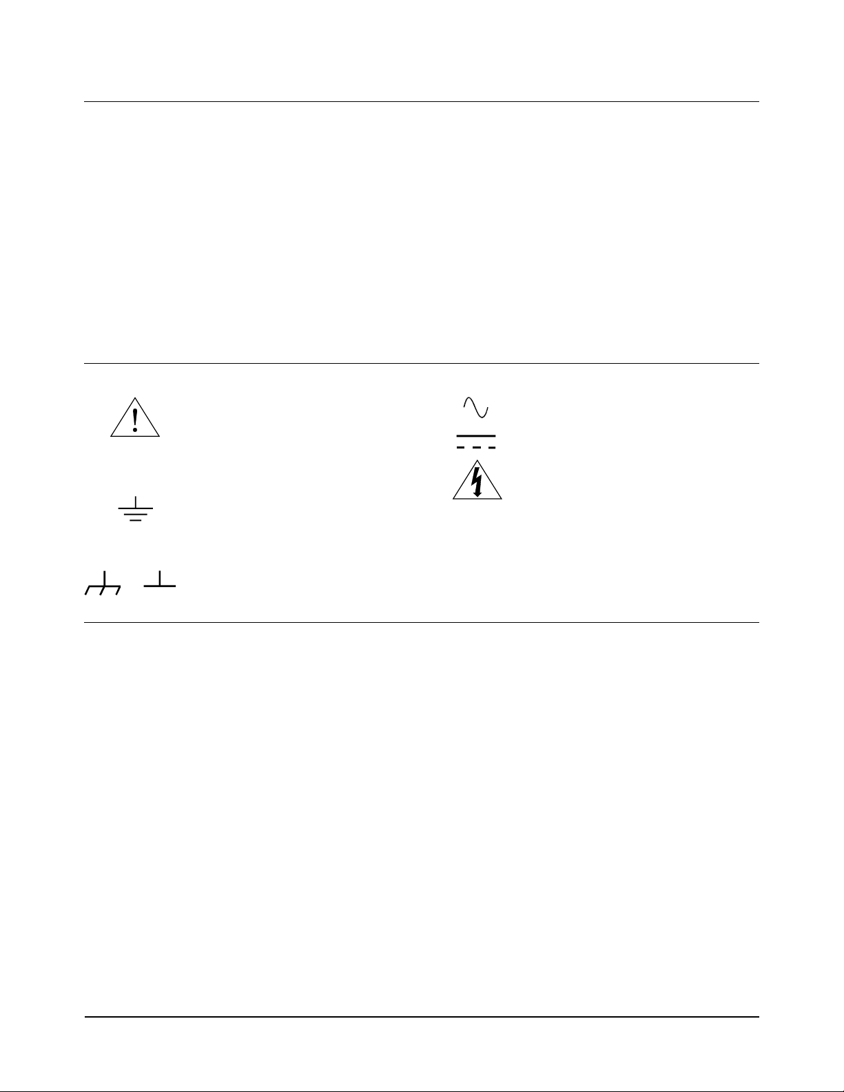
Safety Symbols
Instruction manual symbol affixed to
Instruction manual symbol affixed to
product. Indicates that the user must refer to
product. Indicates that the user must refer to
the manual for specific WARNING or
the manual for specific WARNING or
CAUTION information to avoid personal
CAUTION information to avoid personal
injury or damage to the product.
injury or damage to the product.
Indicates the field wiring terminal that must
be connected to earth ground before
operating the equipmentÅprotects against
electrical shock in case of fault.
WARNING
Alternating current (AC)
Direct current (DC).
Indicates hazardous voltages.
Calls attention to a procedure, practice , or
condition that could cause bodily injury or
death.
or
Frame or chassis ground terminal—typically
connects to the equipment' s metal frame.
CAUTION
Calls attention to a procedure, practice , or
condition that could p ossibly cause damage to
equipment or permane nt loss of data.
WARNINGS
The following genera l safety precautions must be observed during all phases of operation, service, and repair of this produ ct. Failure to
comply with these precautions or with specific warnings elsewhere in this manual violates safety standards of design, manufacture, and
intended use of the product. Hewlett-Packar d Company assumes no liabilit y for the customer's failu re to comply with these requirements.
Ground the equipment: For Safety Class 1 equipment (equipment having a protective earth terminal), an uninterruptible safety earth
ground must be provided from the mains power source to the product input wiring terminals or su pplied power cable.
DO NOT operate the product in an explosive atmosphere or in the presence of flammable gases or fume s.
For continued protection against fire, replace the line fuse(s) only with fuse(s) of the same voltage and current rating and type. DO NOT
use repaired fuses or short-circuited fuse holders.
Keep away from live circuits: Operating personnel must not remove equipment covers or shields. Procedures involving the removal of
covers or shields are for use by service-trained personnel only. Under certain conditi ons, dangerous voltages may exist even with the
equipment swi tched off . To avoid da ngerous el ectrica l shock, DO N OT perform procedure s involvin g cover or sh ield remova l unless you
are qualified to do so.
DO NOT operate damaged equipmen t: Whenever it is possible that the safety protection features built into this product have been
impaired, either through physical damage, excessive moisture, or any other reason, REMOVE POWER a nd do not use the product until
safe operation can be verified by service-trained personnel. If necessary, return the product to a Hewlett-Packard Sales and Service Office
for service and repair to ensure that safety features are maintained.
DO NOT service or adjust alone: Do not attempt internal service or adjustment unless another person, capable of rendering first aid and
resuscitation, is present.
DO NOT substitute parts or modify equipment: Because of the dange r of introd ucing addi tional h azards, do not install substitute parts
or perform any unauthorized mod ification to the product. Return the product to a Hewlett-P ackard Sales and Service Office for service
and repair to ensure that safety features are maintained.
4
Artisan Technology Group - Quality Instrumentation ... Guaranteed | (888) 88-SOURCE | www.artisantg.com
Page 8

Declaration of Conformity
according to ISO/IEC Guide 22 and EN 45014
Manufacturer’s Name: Hewlett-Packard Company
Loveland Manufacturing Center
Manufacturer’s Address: 815 14th Street S.W.
Loveland, Colorado 80537
declares, that the product:
Product Name: A/B to C-Size Active Adapter
Model Number: HP E1403C/HP E1407A
Product Options: All
conforms to the following Product Specifications:
Safety: IEC 1010-1 (1990) Incl. Amend 1 (1992)/EN61010-1 (1993)
CSA C22.2 #1010.1 (1992)
UL 3111-1 (1994)
EMC: CISPR 11:1990/EN55011 (1991): Group1 Class A
EN50082-1:1992
IEC 801-2:1991: 4kVCD, 8kVAD
IEC 801-3:1994: 3 Vm
IEC 801-4:1988: 1 kV Power Line, 0.5 kV Signal Lines
ENV50141: 1993/prEN50082-1 (1995): 3 Vrms
ENV50142: 1994/prEN50082-1 (1995): 1 kVCM, 0.5 kVDM
IEC1000-4-8:1993/prEN50082-1 (1995): 3 A/m
EN61000-4-11: 1994/prEN50082-1 (1995): 30%, 10ms 60%, 100 ms
Supplementary Information: The product herewith complies with the requirements of the Low Voltage Directive
73/23/EEC and the EMC Directive 89/336/EEC (inclusive 93/68/EEC) and carries the "CE" marking acco rdingly.
Tested in a typical configuration in an HP C-Size VXI mainframe.
May 1, 1996
Jim White, QA Manager
European contact: Your local Hewlett-Packard Sales and Service Office or Hewlett-Packard GmbH, Depart-
ment HQ-TRE, Herrenberger Straße 130, D-71034 Böblingen, Germany (FAX +49-7031-14-3143)
5
Artisan Technology Group - Quality Instrumentation ... Guaranteed | (888) 88-SOURCE | www.artisantg.com
Page 9

Notes:
6
Artisan Technology Group - Quality Instrumentation ... Guaranteed | (888) 88-SOURCE | www.artisantg.com
Page 10

Introduction
Chapter 1
General Information
The manual is separated into the following chapters.
Chapter 1 - Gen eral Information. Describes the different adapters.
Chapter 2 - Installation/Removal Instructions. This chapter shows how
to install/remove B-Size VXIbus modules into/from the HP E1403C or
HP E1407A C-Size Adapter Module, and how to ins tall/remove the adapter
module into a C-Size VXIbus Mainframe.
Chapter 3 - Using the Adapters. This chapter shows h ow to use the adapter
modules. It includes a block diagram for both the HP E1403C and
HP E1407A Adapter Modules. The chapter also includes, for the
HP E1407A Adapter Module, instructions on how to use and install the J2
Connector Cable, how to select the direction (to or from the mainframe’s
backplane) of the tr igger signal s on the ECL and TTL tr igger lines , and how
to select unbuffered or buffered SUMBUS connections. Connector pinout
diagrams for both the HP E1403C and HP E1407A are also provided.
Appendix A - Specifications. This appendix details specifications for the
HP E1403C and HP E1407A C-Size Adapter Module.
C-Size Adapter Description
The HP E1403C and HP E1407A Adapter Modules allow an A- or B-Size
VMEbus/VXIbus module to connect to a C-Size VXIbus Mainframe. The
regular adapters connect a single slot VMEbus/VXIbus module to the
mainframe. Option 10 connects two-slot modules to the mainframe
(however, it only conne cts the modul e to the P1 and/or P2 connec tor of only
one slot). The following gives the features of the adapters.
HP E1403C Adapter
Description
Use this adapter to make buffere d connect ions bet ween an A-siz e or B-size
module’s J1 connector and the mainframe’s P1 connector. The adapter has
the following features:
•Mounts with the VMEbus/VXIbus module’s front panel flush with the
front of the adapter.
•Provides direct access to the VMEbus/VXIbus module’s front panel
I/O connections.
•Provides connections to t he J1 connec tor wi th pi n-to- pin co mpat ibilit y
to the mainframe’s P1 connector.
General Information 9Chapter 1
Artisan Technology Group - Quality Instrumentation ... Guaranteed | (888) 88-SOURCE | www.artisantg.com
Page 11

•Meets VMEbus driving and loading specifications.
•Provides proper timing for data Transfer Acknowledgment (DTACK)
and Interrupt Signals (IRQ).
•Provides connectivity for HP B-size modules or any P1-only VXIbus
slave module (Bus Master signals are not provided. These include:
BBSY*, BLCR*, BR0*, BR1*, BR2*, BR3*, SERCLK, SERDAT.)
HP E1407A Adapt er
Description
Use this adapter to make buffere d connect ions bet ween an A-siz e or B-size
module’s J1 connector and the mainframe’s P1 connector, and buffered
connections between a B-size module’s J2 connector and the mai nframe’s P2
connector. The adapter has the following features:
•Mounts with the VMEbus/VXIbus module’s front panel flush wit h the
front of the adapter.
•Provides direct access to the VMEbus/VXIbus module’s front panel
I/O connections.
•Provides connections to t he J1 connec tor wi th pi n-to- pin co mpat ibilit y
to the mainframe’s P1 connector.
•Provides direct connections to the J2 connector with pin-to-pin
compatibility to the mainframe’s P2 connect or.
•Provides buffered data, address, and trigger lines (either ECL or TTL).
•Provides direct SUMBUS connections, or provides fu sed
supply connections to add user provided circuitry (op-amps, for
example) for buffered SUMBUS connections (jumper selectable).
±
12V power
•Provides access to the pins on the outer rows of the J2 connector for
VME modules. These pins may be isolated from the backplane.
•Meets VMEbus driving and loading specifications.
•Provides proper timing for data Transfer Acknowledgment (DTACK)
and Interrupt Signals (IRQ).
•Provides connectivity for HP B-size modules or any P1-only VXIbus
slave module (Bus Master signals are not provided. These include:
BBSY*, BLCR*, BR0*, BR1*, BR2*, BR3*, SERCLK, SERDAT.)
10 General Information Chapter 1
Artisan Technology Group - Quality Instrumentation ... Guaranteed | (888) 88-SOURCE | www.artisantg.com
Page 12

Installation/Removal Instructions
This chapter shows how to install/ remove B-size VXIbus modules into/ from
the HP E1403C or HP E1407A C-Size Adapter Module, and how to
install/remove the adapter module into a C-Size VXIbus Mainframe.
Note The procedures in this chapter shows installation/removal o f the Adapter
Module into/from the HP E1401A High Power Mainframe. The
procedures for other mainframes are similar to these procedures.
Preparing for Installation
•Be sure to set the logical address of the module to be installed into the
adapter to the correct address (see the module manual).
•Be sure to use clean handling and anti-static handling of the module.
Chapter 2
•Be sure there are no external connections to the modules.
Installing A-Size VMEbus Modules (HP E1403C Only)
Install A-Size VMEbus Modules only in the HP E1403C Adapter Module.
Use the following B-Si ze Module in stallation pr ocedure to i nstall an A-Siz e
Module into the adapter module.
Installation/Removal Instructions 11Chapter 2
Artisan Technology Group - Quality Instrumentation ... Guaranteed | (888) 88-SOURCE | www.artisantg.com
Page 13

Installing an Adapter Module with a B-Size VXIbus
Module
The procedure starti ng on the next page sho ws how to install an HP E1403C
or HP E1407A C-Size Adapter Module into an HP E1401A Mainframe.
(The installation procedures for other ma inframes is similar.) Th e procedure
then shows how to install a B-Size VXIb us Mod ule int o the ada pter modul e.
Note During power-up, the resource manager recognizes a module in the slot
with the HP E1403C or HP E1407A Adapter Module installed with or
without a B-Size module installed in the adapter module. Thus, to prevent
any error generation, be sure a B-Size module is installed in the adapter
module before power-up.
Line up the C-Size Adapter Module’s Rails with the Module Guides of an Empty
1
Slot in the Mainframe.
12 Installation/Removal Instructions Chapter 2
Artisan Technology Group - Quality Instrumentation ... Guaranteed | (888) 88-SOURCE | www.artisantg.com
Page 14

Slide the C-Size Adapter Module into the Mainframe.
2
Line up the B-Size Module with the C-Size Adapter Module’s Front Slot and the
3
Mainframe’s Module Guides.
Installation/Removal Instructions 13Chapter 2
Artisan Technology Group - Quality Instrumentation ... Guaranteed | (888) 88-SOURCE | www.artisantg.com
Page 15

Slide the B-Size Module into the C-Size Adapter Module.
4
Tighten the B-Size Module’s Upper and Lower Retainer Screws.
5
14 Installation/Removal Instructions Chapter 2
Artisan Technology Group - Quality Instrumentation ... Guaranteed | (888) 88-SOURCE | www.artisantg.com
Page 16

Removing the Adapter Module and B-Size Module
The following procedure shows how to remove a B-Size VXIbus Module
from an HP E1403C or HP E1407A C-Size Adapter Module and the adapter
module from the mainframe.
Loosen the Upper and Lower Retainer Screws of the B-Size Module inside the
1
C-Size Adapter Module.
Continued on Next Page
Installation/Removal Instructions 15Chapter 2
Artisan Technology Group - Quality Instrumentation ... Guaranteed | (888) 88-SOURCE | www.artisantg.com
Page 17

Using the handles on the B-Size Module, pull the Module out of the C-Size Adapter
2
Module.
NOTE:
When removing the B-size
Module from the Adapter
Module, the Adapter Module
may be pulled out of the
mainframe. If that happens,
carefully pull the B-size Module
out of the Adapter Module,
without damaging any exposed
components on the B-size
Module.
Using the “D” Ring, pull the C-Size Adapter Module out of the Mainframe.
3
16 Installation/Removal Instructions Chapter 2
Artisan Technology Group - Quality Instrumentation ... Guaranteed | (888) 88-SOURCE | www.artisantg.com
Page 18

This chapter shows how to use the adapter modules. It includes a block
diagram for both the HP E1403C and HP E1407A Adapter Modules as well
as connector pinouts. This chapter also includes, for the HP E1407A
Adapter Module, instructions on how to use and install the J2 connector
cable, how to select the di rect ion (t o or fro m the mainf rame’s back plane) of
the trigger signals on the ECL and TTL trigger lines, and how to select
unbuffered or buffered SUMBUS connections.
HP E1403C Block Diagram
Figure 3-1 shows the block diagram for the HP E1403C C-Size Adapter
Module.
Chapter 3
Using the Adapters
Figure 3-1. HP E1403C Block Diagram
Using the Adapters 17Chapter 3
Artisan Technology Group - Quality Instrumentation ... Guaranteed | (888) 88-SOURCE | www.artisantg.com
Page 19

HP E1403C Connec tor Pinout
Figure 3-2 shows the P1 and J1 connector’s pinout for the HP E1403C
Adapter Module.
Figure 3-2. HP E1403C P1 and J1 Connector Pinout
18 Using the Adapters Chapter 3
Artisan Technology Group - Quality Instrumentation ... Guaranteed | (888) 88-SOURCE | www.artisantg.com
Page 20

HP E1407A Block Diagram
Figure 3-3 shows the block diagram for the HP E1407A C-Size Adapter
Module.
Figure 3-3. HP E1407A Block Diagram
Using the Adapters 19Chapter 3
Artisan Technology Group - Quality Instrumentation ... Guaranteed | (888) 88-SOURCE | www.artisantg.com
Page 21

HP E1407A Connec tor Pinout
Figure 3-4 shows the P1 and J1 connecto r’s pinout, and Figure 3-5 sho ws the
P2 and J2 connector’s pinout for the HP E1407A Adapter Module.
Figure 3-4. HP E1407A P1 and J1 Connector Pinout
Figure 3-5. HP E1407A P2 and J2 Connector Pinout
20 Using the Adapters Chapter 3
Artisan Technology Group - Quality Instrumentation ... Guaranteed | (888) 88-SOURCE | www.artisantg.com
Page 22

Installing the J2 Connector Cable (HP E1407A Only)
Purpose of the
J2 Cable
Caution Damage to a VMEbus module, adapter module, mainframe, or
The HP E1407A C-Size Adapter Module is shipped with a long and short J2
Connector Cables. The long J2 cable allows for direct access to the outer
rows of the J2 connector of the B-Size module (that is, VMEbus modules
that utilize the outer rows of J2) inside the adapter module. The short J2
cable makes internal connections between the P2 and J2 connectors of the
adapter module to allow for connections between the J2 connector of the
B-Size module inside the adapter module and the P2 connector of the
mainframe. Use this for VXIbu s modul es t hat uti li ze the outer rows of J2.
If your module has no outer row connections of J2, do not install either
cable.
See Figure 3-6 for the J2 connector’s pinout diagram.
all three may result if using the short cable in an adapter
module with a VMEbus module.
Install the J2 Cable Do the following to install either J2 Cable:
On the C-Size VXIbus Adapter Module, remove the 7 Top Shield Retainer Screws
1
and Top Shield.
Using the Adapters 21Chapter 3
Artisan Technology Group - Quality Instrumentation ... Guaranteed | (888) 88-SOURCE | www.artisantg.com
Page 23

Plug in either the Short or Long Ribbon (J2) Cable.
2
Reinstall the Top Shield and Retainer Screws on the C-Size Adapter Module.
3
22 Using the Adapters Chapter 3
Artisan Technology Group - Quality Instrumentation ... Guaranteed | (888) 88-SOURCE | www.artisantg.com
Page 24

Ribbon Cable (J2)
Connector Pinout
Figure 3-6 shows the pinout for the HP E1407A ribbon cable connectors
(J2).
Figure 3-6. HP E1407A Ribbon Cable Connectors (J2)
Using the Adapters 23Chapter 3
Artisan Technology Group - Quality Instrumentation ... Guaranteed | (888) 88-SOURCE | www.artisantg.com
Page 25

Selecting the TTL Trigger Direction (HP E1407A Only)
The HP E1407A C-Size Adapter Module has a switch that allows you t o set
the trigger signal direction of the TTL0–TTL7 Trigger Lines. Figure 3-7
shows that the TTL7 Trigger Signal comes from the B-Size Module, and
TTL0–TTL6 from the Mainframe's VXI Backplane. Use the illustra tion as
a guide to set the appropriate trigger directions for your application.
Figure 3-7. Selecting the TTL Trigger Signal Direction
24 Using the Adapters Chapter 3
Artisan Technology Group - Quality Instrumentation ... Guaranteed | (888) 88-SOURCE | www.artisantg.com
Page 26

Selecting the ECL Trigger Direction (HP E1407A Only)
The HP E1407A C-Size Adapter Module has a switch that allows you t o set
the trigger signal di rection of the ECL0 and ECL1 Trigge r Lines. Figure 3-8
shows that the ECL1 Trigger Signal comes from the B-Size Module, and
ECL0 from the Mainframe’s VXI Ba ckplane. Use the i llustrati on as a guide
to set the appropriate trigger directions for your application.
Figure 3-8. Selecting the ECL Trigger Signal Direction
Using the Adapters 25Chapter 3
Artisan Technology Group - Quality Instrumentation ... Guaranteed | (888) 88-SOURCE | www.artisantg.com
Page 27

SUMBUS Configurations (HP E1407A Only)
Disconnecting
the SUMBUS
The ribbon cable and a pai r of ju mpers connect the SUMBUS to the outpu t
connectors (i.e., to the B-Size Module). Use Figure 3-9 to disconnect
(i.e., remove the jumpers) or connect the SUMBUS.
Figure 3-9. SUMBUS Jumper Configurations
Adding Buffer
Circuitry to the
SUMBUS
26 Using the Adapters Chapter 3
Artisan Technology Group - Quality Instrumentation ... Guaranteed | (888) 88-SOURCE | www.artisantg.com
The adapter module has no circuitry available to buffer the SUMBUS.
However, there is a breadboard area on the PC board in the HP E1407A
Adapter that allows you to add your own circuitry ( e.g., op-amps) to provide
buffering for the SUMBUS. The bre adboard area also incl udes connecti ons
to the ±12V Power Supplies.
You can add buffer circuitry either for SUMBUS signals coming from the
B-Size Module in the Adapter Module or from the Mainframe’s VXI
Backplane. Use Figure 3-9 to select the appropriate jumpers for your
application, and to locate the breadboard area.
Page 28

Appendix A
HP E1403C and HP E1407A Specifications
Product Characteristics
•P1 and P2 extension fully buffered (P1 only on HP E1403C).
•Slave-only capability; cannot be used in Slot 0 with bus masters.
•Unlimited number of adapters per mainframe.
•1-slot wide.
•Option 10 is 2-slot wide. Only the P1 an d/o r P2 connect ors of a singl e
slot are used.
•Replacement fuses are subminiature 4A, 125V
(Littelfuse is recommended).
Power Requirements
Cooling Requirements
0.02mm H2O @0.10Liter/sec Air Flow for 10°C rise.
Voltage:
Peak Module Current (A): 0.10 0.07
Dynamic Module Current ( A): 0.01 0.01
* HP E1407A Only
+5V +12V*
HP E1403C and HP E1407A Specifications 27Appendix A
Artisan Technology Group - Quality Instrumentation ... Guaranteed | (888) 88-SOURCE | www.artisantg.com
Page 29

Notes:
28 HP E1403C and HP E1407A Specifications Appendix A
Artisan Technology Group - Quality Instrumentation ... Guaranteed | (888) 88-SOURCE | www.artisantg.com
Page 30

Index
A
Adapter Description , 9
HP E1403C, 9
HP E1407A, 10
option 10, 9
Adding SUMBUS Buffer Circuitry, 26
A-Size VMEbus Modules, installing, 11
B
Backplane
ECL trigger signals
SUMBUS buffer circuitry, 26
TTL trigger signals, 24
Block Diagram
HP E1403C
HP E1407A, 19
B-Size VXIbus Modules
ECL trigger signal
installing, 12–14
removing, 15–16
SUMBUS buffer circuitry, 26
TTL trigger signal, 24
, 17
, 25
, 25
C
Cable
ribbon cable (J2)
description
installing, 21, 23
pinouts, 23
Certification, 3
Connecting the SUMBUS, 26
Cooling Requirements, 27
, 21
D
Declaration of Conformity, 5
Description
adapters
HP E1403C, 9
HP E1407A, 10
, 9
ECL trigger, 25
ribbon cable (J2), 21, 23
SUMBUS, 26
TTL trigger, 24
Descriptio n (continued)
option 10
ribbon cable (J2), 21, 23
Disconnecting the SUMBUS, 26
Documentation History, 4
, 9
E
ECL Trigger Direction, 25
F
Fuses, 27
H
HP E1403C
A-size VMEbus modules, installing
block diagram, 17
B-size VXIbus modules
installing
removing, 15–16
description, 9
pinout, 18
specifications, 27
HP E1407A
block diagram
B-size VXIbus modules
ECL trigger signals
installing, 12–14
removing, 15–16
SUMBUS buffer circuitry, 26
TTL trigger signals, 24
description, 10
ECL trigger direction, 25
pinout, 20
ribbon cable (J2), 23
ribbon cable (J2), installing, 21, 23
specifications, 27
SUMBUS, 26
TTL trigger direction, 24
, 12–14
, 19
, 25
, 11
Index 29
Artisan Technology Group - Quality Instrumentation ... Guaranteed | (888) 88-SOURCE | www.artisantg.com
Page 31

I
Installation
and removal instructions
A-size VMEbus modules, 11
B-size VXIbus modules, 12–14
HP E1407A, ribbon cable (J2), 21, 23
preparation, 11
, 11
M
Mainframe
backplane
ECL trigger signals
SUMBUS buffer circuitry, 26
TTL trigger signals, 24
installing
A-size VMEbus modules
B-size VXIbus modules, 12–14
removing modules from, 15–16
, 25
O
Option 10, description, 9
P
Pinouts
HP E1403C
HP E1407A, 20
ribbon cable (J2), 23
Power Requirements, 27
Preparing for Installation, 11
, 18
, 11
Switches
ECL trigger
TTL trigger, 24
, 25
T
Triggers
B-size modules
ECL, 25
mainframe VXI backplane, 24–25
TTL, 24
, 24–25
trigger direction, 24
U
Using the Adapters, 17
V
VXIplug&play Example Programs
See VXIplug&play Online Help
VXIplug&play Function Reference
See VXIplug&play Online Help
VXIplug&play Programming
See VXIplug&play Online Help
VXIplug&play Soft Front Panel
See VXIplug&play Online Help
W
WARNINGS, 4
R
Removing B-size VXIbus Modules, 15–16
Ribbon Cable (J2)
description
installing, 21, 23
pinouts, 23
, 21
S
Safety Warnings, 4
Selecting
ECL trigger direction
TTL trigger direction, 24
Specifications, 27
SUMBUS
adding buffer circuitry
configurations, 26
30 Index
Artisan Technology Group - Quality Instrumentation ... Guaranteed | (888) 88-SOURCE | www.artisantg.com
, 25
, 26
Page 32

Artisan Technology Group is your source for quality
new and certied-used/pre-owned equipment
• FAST SHIPPING AND
DELIVERY
• TENS OF THOUSANDS OF
IN-STOCK ITEMS
• EQUIPMENT DEMOS
• HUNDREDS OF
MANUFACTURERS
SUPPORTED
• LEASING/MONTHLY
RENTALS
• ITAR CERTIFIED
SECURE ASSET SOLUTIONS
SERVICE CENTER REPAIRS
Experienced engineers and technicians on staff
at our full-service, in-house repair center
Instra
Remotely inspect equipment before purchasing with
our interactive website at www.instraview.com
Contact us: (888) 88-SOURCE | sales@artisantg.com | www.artisantg.com
SM
REMOTE INSPECTION
View
WE BUY USED EQUIPMENT
Sell your excess, underutilized, and idle used equipment
We also offer credit for buy-backs and trade-ins
www.artisantg.com/WeBuyEquipment
LOOKING FOR MORE INFORMATION?
Visit us on the web at www.artisantg.com for more
information on price quotations, drivers, technical
specications, manuals, and documentation
 Loading...