

Page 1

Contents
HP E1368A/69A/70A Modules User’s Manual
Warranty . . . . . . . . . . . . . . . . . . . . . . . . . . . . . . . . . . . . . . . . . . 5
WARNINGS . . . . . . . . . . . . . . . . . . . . . . . . . . . . . . . . . . . . . . . . 6
Safety Symbols . . . . . . . . . . . . . . . . . . . . . . . . . . . . . . . . . . . . . . 6
Declaration of Conformity . . . . . . . . . . . . . . . . . . . . . . . . . . . . . . . . . 7
Reader Comment Sheet . . . . . . . . . . . . . . . . . . . . . . . . . . . . . . . . . . 9
1. Getting Star ted w it h th e HP E 1368A/69A/70A . . . . . . . . . . . . . . . . . . . . . . . . . 11
Using This Chapter . . . . . . . . . . . . . . . . . . . . . . . . . . . . . . . . . . . . 11
Microwave S witch Description . . . . . . . . . . . . . . . . . . . . . . . . . . . . . . 11
Power Suppl y Circuit . . . . . . . . . . . . . . . . . . . . . . . . . . . . . . . . . 13
HP E1368A Switches . . . . . . . . . . . . . . . . . . . . . . . . . . . . . . . . . 13
Instrument Definition . . . . . . . . . . . . . . . . . . . . . . . . . . . . . . . . . . . 14
Programming the Microwave Switch . . . . . . . . . . . . . . . . . . . . . . . . . . . 14
Card Numbers . . . . . . . . . . . . . . . . . . . . . . . . . . . . . . . . . . . . . 14
Channel Numbers . . . . . . . . . . . . . . . . . . . . . . . . . . . . . . . . . . . 15
Channel Address . . . . . . . . . . . . . . . . . . . . . . . . . . . . . . . . . . . 15
SCPI Command F ormat Used in Th is Ma nua l . . . . . . . . . . . . . . . . . . . . 16
Initial Opera ti on . . . . . . . . . . . . . . . . . . . . . . . . . . . . . . . . . . . . . . 16
2. Configuring the HP E1368A/69A/70A Modules . . . . . . . . . . . . . . . . . . . . . . . . 17
Using This Chapter . . . . . . . . . . . . . . . . . . . . . . . . . . . . . . . . . . . . 17
Warnings and Cautions . . . . . . . . . . . . . . . . . . . . . . . . . . . . . . . . . . 17
Setting the Address Switch . . . . . . . . . . . . . . . . . . . . . . . . . . . . . . . . 18
Selecting the Interrupt Pri ori ty . . . . . . . . . . . . . . . . . . . . . . . . . . . . . . 19
Installing Switches on the HP E1369A . . . . . . . . . . . . . . . . . . . . . . . . . . 20
Installing Switches on the Modul e . . . . . . . . . . . . . . . . . . . . . . . . . . 20
Connecting Switches External to the Module . . . . . . . . . . . . . . . . . . . . 23
Selecting Switch Power . . . . . . . . . . . . . . . . . . . . . . . . . . . . . . . . 24
Connecting Field Wiring . . . . . . . . . . . . . . . . . . . . . . . . . . . . . . . 25
Installing a Switch or Atten uator on the HP E 1370A Microwa ve Switch/At ten ua tor
Card . . . . . . . . . . . . . . . . . . . . . . . . . . . . . . . . . . . . . . . . . . . 26
Installing a Switch or Attenuator on the Module . . . . . . . . . . . . . . . . . . . 26
Connecting Field Wiring . . . . . . . . . . . . . . . . . . . . . . . . . . . . . . . 28
3. Using the HP E1368A/69A/70A Modules . . . . . . . . . . . . . . . . . . . . . . . . . . . 29
Using This Chapter . . . . . . . . . . . . . . . . . . . . . . . . . . . . . . . . . . . . 29
Microwave Switch Comma nd s . . . . . . . . . . . . . . . . . . . . . . . . . . . . . . 29
Reset Conditions . . . . . . . . . . . . . . . . . . . . . . . . . . . . . . . . . . . . . . 30
Switching Channels . . . . . . . . . . . . . . . . . . . . . . . . . . . . . . . . . . . . 31
Example: Single Ch annel S witching . . . . . . . . . . . . . . . . . . . . . . . . . 31
Examp le: Single Ch an n el S wit ch in g using EXTer n a l POWER . . . . . . . . . . . 32
Example: Channel Switchin g usin g the E 1370 A and the 3336 6K Micr ow av e Switch 33
Examp le: Multipl e Ch an n el S wit ch in g using EXTer n a l POWER . . . . . . . . . . 35
HP E1368A/69A/70A Modules User’s Manual Con te nts 1
Page 2

Examp le: Transfer S witch Usin g Two 3-P ort Switch es . . . . . . . . . . . . . . . 36
Examp le: Transfer S witch Usin g On e 5 -Port Switch . . . . . . . . . . . . . . . . 37
Examp le: 4 x 1 Multiplexer . . . . . . . . . . . . . . . . . . . . . . . . . . . . . . 38
Scannin g Cha nne ls . . . . . . . . . . . . . . . . . . . . . . . . . . . . . . . . . . . . . 39
Example: S c anning Channels . . . . . . . . . . . . . . . . . . . . . . . . . . . . . 40
Example: U sing the Sc an Compl et e Bit . . . . . . . . . . . . . . . . . . . . . . . 41
Recalling and Saving States . . . . . . . . . . . . . . . . . . . . . . . . . . . . . . . . 43
Storing Sta te s . . . . . . . . . . . . . . . . . . . . . . . . . . . . . . . . . . . . . 43
Recalling State s . . . . . . . . . . . . . . . . . . . . . . . . . . . . . . . . . . . . 43
Detecting Error Conditi ons . . . . . . . . . . . . . . . . . . . . . . . . . . . . . . . . 43
Synchronizing the Microwave Switch . . . . . . . . . . . . . . . . . . . . . . . . . . . 45
Synchronizing Instruments . . . . . . . . . . . . . . . . . . . . . . . . . . . . . . 45
Querying the Micr ow a ve Switch . . . . . . . . . . . . . . . . . . . . . . . . . . . . . 46
4. HP E1368A/ 69A/70A Comma nd Referenc e . . . . . . . . . . . . . . . . . . . . . . . . . . 47
Using This Chapter . . . . . . . . . . . . . . . . . . . . . . . . . . . . . . . . . . . . 47
Command Types . . . . . . . . . . . . . . . . . . . . . . . . . . . . . . . . . . . . . . 47
Common Command Format . . . . . . . . . . . . . . . . . . . . . . . . . . . . . 47
SCPI Command F ormat . . . . . . . . . . . . . . . . . . . . . . . . . . . . . . . 47
Linking Commands . . . . . . . . . . . . . . . . . . . . . . . . . . . . . . . . . . 49
SCPI Command Reference . . . . . . . . . . . . . . . . . . . . . . . . . . . . . . . . 50
ABORt . . . . . . . . . . . . . . . . . . . . . . . . . . . . . . . . . . . . . . . . . . . 50
ARM . . . . . . . . . . . . . . . . . . . . . . . . . . . . . . . . . . . . . . . . . . . . 51
:COUNt . . . . . . . . . . . . . . . . . . . . . . . . . . . . . . . . . . . . . . . . 51
:COUNt? . . . . . . . . . . . . . . . . . . . . . . . . . . . . . . . . . . . . . . . 52
DISPlay . . . . . . . . . . . . . . . . . . . . . . . . . . . . . . . . . . . . . . . . . . 53
:MONitor:CARD . . . . . . . . . . . . . . . . . . . . . . . . . . . . . . . . . . . 53
:MONitor[:STATe] . . . . . . . . . . . . . . . . . . . . . . . . . . . . . . . . . . 54
:MONitor[:STATe]? . . . . . . . . . . . . . . . . . . . . . . . . . . . . . . . . . 54
INITiate . . . . . . . . . . . . . . . . . . . . . . . . . . . . . . . . . . . . . . . . . . 55
:CONTinuous . . . . . . . . . . . . . . . . . . . . . . . . . . . . . . . . . . . . . 55
:CONTinuous? . . . . . . . . . . . . . . . . . . . . . . . . . . . . . . . . . . . . 56
[:IMMediate] . . . . . . . . . . . . . . . . . . . . . . . . . . . . . . . . . . . . . 56
OUTPut . . . . . . . . . . . . . . . . . . . . . . . . . . . . . . . . . . . . . . . . . . 57
[:STATe] . . . . . . . . . . . . . . . . . . . . . . . . . . . . . . . . . . . . . . . 57
[:STATe] ? . . . . . . . . . . . . . . . . . . . . . . . . . . . . . . . . . . . . . . . 57
[ROUTe:] . . . . . . . . . . . . . . . . . . . . . . . . . . . . . . . . . . . . . . . . . 58
CLOSe . . . . . . . . . . . . . . . . . . . . . . . . . . . . . . . . . . . . . . . . 58
CLOSe? . . . . . . . . . . . . . . . . . . . . . . . . . . . . . . . . . . . . . . . . 59
OPEN . . . . . . . . . . . . . . . . . . . . . . . . . . . . . . . . . . . . . . . . . 59
OPEN? . . . . . . . . . . . . . . . . . . . . . . . . . . . . . . . . . . . . . . . . 60
SCAN . . . . . . . . . . . . . . . . . . . . . . . . . . . . . . . . . . . . . . . . . 60
SCAN:MODE . . . . . . . . . . . . . . . . . . . . . . . . . . . . . . . . . . . . . 61
SCAN:MODE? . . . . . . . . . . . . . . . . . . . . . . . . . . . . . . . . . . . . 61
STATus . . . . . . . . . . . . . . . . . . . . . . . . . . . . . . . . . . . . . . . . . . 62
:OPERati on:E N ABle . . . . . . . . . . . . . . . . . . . . . . . . . . . . . . . . . 63
:OPERati on:E N ABle? . . . . . . . . . . . . . . . . . . . . . . . . . . . . . . . . 63
:OPERati on[:E VENt]? . . . . . . . . . . . . . . . . . . . . . . . . . . . . . . . . 64
2 HP E1368A/69A/70A Modules User’s Manual Contents
Page 3

SYSTem . . . . . . . . . . . . . . . . . . . . . . . . . . . . . . . . . . . . . . . . . . 65
:CDEScript i on? . . . . . . . . . . . . . . . . . . . . . . . . . . . . . . . . . . . . 65
:CPON . . . . . . . . . . . . . . . . . . . . . . . . . . . . . . . . . . . . . . . . 65
:CTYPe? . . . . . . . . . . . . . . . . . . . . . . . . . . . . . . . . . . . . . . . 66
:ERRor? . . . . . . . . . . . . . . . . . . . . . . . . . . . . . . . . . . . . . . . . 66
TRIGger . . . . . . . . . . . . . . . . . . . . . . . . . . . . . . . . . . . . . . . . . . 67
[:IMMediate] . . . . . . . . . . . . . . . . . . . . . . . . . . . . . . . . . . . . . 67
:SOURce . . . . . . . . . . . . . . . . . . . . . . . . . . . . . . . . . . . . . . . 67
:SOURce? . . . . . . . . . . . . . . . . . . . . . . . . . . . . . . . . . . . . . . . 69
IEEE 488.2 Common Commands . . . . . . . . . . . . . . . . . . . . . . . . . . . . . 70
Command Quick Reference . . . . . . . . . . . . . . . . . . . . . . . . . . . . . . . . 71
A. HP E1368A/69A/70A Specifications . . . . . . . . . . . . . . . . . . . . . . . . . . . . . . 73
B. HP E1368A/ 69A/70A Regi sters . . . . . . . . . . . . . . . . . . . . . . . . . . . . . . . . 75
Register Definiti on s . . . . . . . . . . . . . . . . . . . . . . . . . . . . . . . . . . . . 75
Address ing the Register s . . . . . . . . . . . . . . . . . . . . . . . . . . . . . . . . . 76
Reading the Re gisters . . . . . . . . . . . . . . . . . . . . . . . . . . . . . . . . . . . 76
ID and Device T ype Register s . . . . . . . . . . . . . . . . . . . . . . . . . . . . 76
Status/C ont rol Register . . . . . . . . . . . . . . . . . . . . . . . . . . . . . . . . 77
Channel Enable Register . . . . . . . . . . . . . . . . . . . . . . . . . . . . . . . 77
Writing to the Registers . . . . . . . . . . . . . . . . . . . . . . . . . . . . . . . . . . 77
Channel Enable Register . . . . . . . . . . . . . . . . . . . . . . . . . . . . . . . 77
C. HP E1368A/69A/70A Error Messages . . . . . . . . . . . . . . . . . . . . . . . . . . . . . 79
HP E1368A/69A/70A Modules User’s Manual Con te nts 3
Page 4

Notes
4 HP E1368A/69A/70A Modules User’s Manual Contents
Page 5

Certification
Hewlett-Pac kard Compa ny certif ies that this product m et its published sp ecifi cation s at the time of shipment from the factory. H ewlettPackard further certifies that its calibration measurements are traceable to the United Stat es Nation al Instit ute of Stand ard s and Technology (for m erl y Nat ional Bur ea u of Standar ds ), to the ex tent allo wed by that orga ni zati on’ s cal ib rat ion f ac ili t y, and t o th e calibration
facilities of ot her International Standards Organiz at i on members.
Warranty
This Hewlet t-Pa ck ar d product is warr ante d agai nst de fect s in mate rials and w orkmansh ip for a period of three years from date of shipment. Duration and cond iti ons of warranty for this produ ct ma y be super seded when the product i s i nt egrated into ( becomes a part of)
other HP product s. Du ring the warranty period, Hewlet t -Pa ckard Company will, at its option, either repair or repl ace products whi ch
prove to be defective.
For warranty se r vice or repair, this product must be retur ned to a service faci l ity designated by Hewlett-Packar d (HP). Buyer sha l l prepay shipping cha rges to HP and HP sh all pay shipping charge s t o re tu rn the product to B uyer. However, Buyer shall pay all shi p ping
charges, duties, and taxe s for products returned to HP from anot her count r y.
HP warrants that its softwar e and firmwar e designa ted b y HP for use with a product will execute its programmin g instru cti ons wh en
properly installe d on that product. HP does not warrant that the operat ion of the product, or software , or firmware will be uninterrupted
or er ro r f r ee.
Limitation Of Warrant y
The foreg oin g warra nt y sh al l not apply t o defects resul ting from improper or inade quate mainte nance by Buyer, Buyer-supplied products or interfacing, unauthori ze d m odificati on or misus e, operation outside of the environmenta l specificat i ons for the product, or improper site prep arat i on or maint ena nce.
The design and imp le mentation of any circuit on this product is the sole responsibility of th e Buyer. HP does not warra nt th e Buyer’s
circuitr y or malfunctions of HP products that result from the Bu yer’s circuitry. In addition, HP does not warrant any damage that occurs as a result of the B uyer’s circuit or any defects that result from Buyer-supplied pr oduct s.
NO OTHER WARRANTY IS EXPRESSED OR IMPLIED. HP SPECIFICALLY DISCLAIMS THE IMPLIED W ARR ANTIES OF
MERCHANTABILITY AND FITNESS FOR A PARTICULAR PURPOSE.
Exclusive Remedie s
THE REMED IES PROVIDED HEREIN ARE BUYER’S SOLE AND EXCLUSIVE REMEDIES. HP SHALL NOT BE LIABLE
FOR ANY DIRECT, INDIRECT, SPECIAL, INCIDENTAL, OR CONSEQUENTIAL DAMAGES, WHETHER BASED ON CONTRACT, TORT, OR ANY OTHER LEGAL THE ORY.
Notice
The information contained in this document is subject to change without notice. HEWLETT-PACKARD (HP) MAKES NO WARRANTY OF ANY KIND W ITH REGARD TO THIS MATERIAL, INCLUDING, BUT NOT LIMITED TO, THE IMPLIED WARRANTIES OF MERCHANTABILITY AND FITNESS FOR A PARTICULAR PURPOSE. HP shall not be liable for errors contained
herein or for incidental or consequential damages in connection with the furnishing, performance or use of this material. This document c ontains proprieta ry information which is protected by copyright. A ll rights are rese rved. No part of this document may be photocopied, reproduced, or translate d to another lan guage wit h out the prior written consent of Hewlett -Packar d C ompany. HP assumes no
responsibility for the use or reliability of its software on equipment that is not furnished by HP.
Restricted Rights Legen d
Use, dupli ca tion or discl osu re by the U. S. Go vernme nt is subje ct to rest rict i ons as set fort h in subparagraph (c)(1) (i i) of the Right s in
Technical Data and Comp uter Softwa re clause in D F ARS 252.227-701 3.
Hewlett-Packar d Company
3000 Hanover Street
Palo Alto, Cal if ornia 943 04 U.S. A.
Rights for non-DOD U.S. Government Departments and Agen ci es are as set f orth in F AR 52.227 -19 (c) (1,2).
HP E1368A, E1369A, E1370A Microwave Swit ch and Driver Modules User’s Manu al
Copyright © 1995 He wle tt-Pa cka rd Company. All Right s Reser ve d.
Edition 3
HP E1368A, E1369A, E1370A Microwave Switch and Driver Modules User’s Manual 5
Page 6

Documentatio n History
All Editions and Updates of this manual and their creation date are listed below. The first Edition of the manual is Edition 1. The Edition number increment s by 1 whenever the manua l is revised . Updates , which are issued betw een Edi ti ons, c ontain repla ce ment pa ges
to correct or add additional information to the current Edition of the manual. Whenever a new Edition is created, it wil l contain all of
the Update inf ormat ion for the pre viou s Editi on. Each new Ed iti on or Update also incl ude s a revis ed c op y of this documentation history page.
Edition 1 . . . . . . . . . . . . . . . . . . . . . . . . . . . . . . . . . . . . . . . . . . . Dece mbe r, 1989
Edition 2 . . . . . . . . . . . . . . . . . . . . . . . . . . . . . . . . . . . . . . . . . . . . . August, 1990
Edition 3 . . . . . . . . . . . . . . . . . . . . . . . . . . . . . . . . . . . . . . . . . . . . . . . June, 1995
Safety Symbols
Instruction manual symbol affixed to product. Indicat es that the user must re fer to the
manual for specific WARNING or CAUTION information to avoid personal injury
or damage to the product.
Indicates the field wiring terminal that must
be connected to earth ground before operating the equipment—protects against electrical shock in case of fault.
Frame or chassis ground termi nal — t ypi-
or
cally connects to the equipment’s metal
frame.
WARNING
CAUTION
Alternating current (AC).
Direct curren t (DC).
Indicate s ha za rdous voltage s.
Calls at te nt i on t o a pr ocedure, practice, or
condition that could cause bodily injury or
death.
Calls at te nt i on t o a pr ocedure, practice, or condition that could possibly cause damage to
equipme nt or perma nen t los s of data.
WARNINGS
The following ge ner al safet y prec aut ions mus t be observed du ring al l phas es of oper ation , ser vice , and repai r of this pr oduct.
Failure to comply with these precautions or with specific warnings elsewhere in this manual violates safety standards of design,
manufacture, and inten ded use of the product. Hewlett-Pac kar d Company assumes no liabilit y for the cust o mer’s fai lure to
comply with these requirements.
Ground the equipment: For Safety Cl as s 1 equipmen t (equ ipment ha vin g a protective ea rth ter mi nal) , an unint erru ptib le sa fety earth
ground must be provide d from the ma in s power sour ce to the produ ct input wi rin g termi nals or suppli ed power cable .
DO NOT operate the produc t in an explosive at mospher e or in the presen ce of flammable gases or fume s.
For continued protect ion a gainst fire, repl ace the line fuse (s) only with fuse(s) of the same voltage and curre nt rating and ty pe .
DO NOT use repaired fuses or short-circui ted fuse holders.
Keep away from live circuits: Operatin g personnel must not remove equipment covers or shields. Procedures involving the removal
of covers or shields are for use by service-trained personn el only. Under certain conditi ons , danger ous v oltage s m ay exist even with the
equipment switched off. To avoid dangerous ele ctrical shock , DO NOT perf orm procedures involving cover or shield removal unless
you are qualified to do so.
DO NOT operate damaged equipment: Whene ver it i s p ossibl e tha t the sa fe ty protection features bui l t int o thi s pr oduct have been impaired, eithe r t hr ough physical da mage, excessive moisture, or any other reason, REMOVE POWER and do not use the product until
safe operation can be verified by service-trained personnel. If necessary, return the product to a Hewlett -P ackar d Sales and Se rvice Office for service and repair to ensure that safety features are maintai ned.
DO NOT service or adjust alon e: Do not attempt internal service or adjustment unless another person, capable of rendering first aid
and resuscitation, is present.
DO NOT substitute parts or modify equipment: Because of the danger of introducin g additional hazar ds, do not install substitute
parts or perform any unauthorized modifica tion to the product. Retur n the product to a Hewlet t-P ackar d Sales and Ser vice O ffice for
service and repair to ensure th at safety feature s are maintai ned.
6 HP E1368 A, E1 36 9A , E13 70 A Microwave Switch a nd Driver Modules User’s Manual
Page 7

Declaration of Conformity
according to ISO/IEC Guide 22 and EN 45014
Manufacturer’s Name: Hewlett-Pa ckar d C ompany
Loveland Manufacturing Center
Manufact urer’s Addre s s: 815 14th Street S.W.
Loveland, Colorado 80537
declares, that the product:
Product Name: HP E1368A Microwave Switch, E1 369A Microwave Switch Dri v er ,
E1370A Microw a ve S witch/ Att en uator
Model Number : E1368A, E1369A, E1370 A
Produc t Opt ion s: All
conforms to the following Pr od uct Spe cifi cati ons :
Safety: IEC 1010-1 (1990) Incl . Amend 1 (1992) /E N610 10-1 (1993)
CSA C22.2 #1010.1 (1 992)
UL 1244
EMC: CISPR 11:1990/EN55011 (1991): Group1 Class A
IEC 801-2:1991/ E N5008 2-1 (1 992) : 4kVCD, 8k VA D
IEC 801-3:1984/ E N5008 2-1 (1 992) : 3 V/m
IEC 801-4:1988/ E N5008 2-1 (1 992) : 1kV P ower Lin e
.5kV Signal Line s
Supplementary Information: The product her ewi th c ompl ies wit h th e requiremen ts of t he Low Voltage Directive
73/23/EEC and the EMC Directive 89/336/ EEC and carri es the CE-mark ing acc ordingly.
Tested in a typical c onfigur at ion in an HP B-Size VXI mainframe.
April, 1995 Jim White, QA Manager
European conta ct: Your loca l He wlett-Pa cka rd Sales a nd Servi ce O ffic e or Hewlett- Packa rd GmbH, Departm ent
HQ-TRE, Herr en ber ger Straß e 13 0, D- 71034 Böblingen, Germany (FAX +49-7031-14-3143).
HP E1368A, E1369A, E1370A Microwave Switch and Driver Modules User’s Manual 7
Page 8

Notes
8 HP E1368 A, E1 36 9A , E13 70 A Microwave Switch a nd Driver Modules User’s Manual
Page 9
Please fold and t ape for mailing
Reader Comment Sheet
HP E1368A, E1369A, E1370A Microwave S witch and Driver Module s User’s Manual
Editio n 3
You can help us improve our manual s b y sharing your commen ts and sug gesti ons. In apprec iat ion of your time, we will
enter yo u in a quarterly drawing for a Hewlett -Pac kar d Palmt op Personal Computer (U.S. government employees
cannot participate in the drawing).
Your Name
C ompany N a me
Job Title
Address
City, State/Province
Country
Zip/Postal Code
Telephone Number with Area Code
Please list the syste m contr ol ler , oper ati ng syste m, pr ogr a m ming la ng uage, and pl ug-in mo dules you are using.
fold here
BUSINESS REPLY MAIL
FIRST CLASS PERMIT NO. 37 LOVELAND,CO
HEWLETT-PACKARD COMPANY
cut along this line
Measurement Systems Division
Learning Products Department
P.O. Box 301
Loveland, CO 80539-9984
NO POSTAGE
NECESSARY
IF MAILED
IN THE
UNITED STATES
fold here
Please penci l-in one circl e for each statement below: Disagree Agree
• The documentation is well organized. OOOOO
•Instructions are easy to understand. OOOOO
•The documentation is clearly written. OOOOO
•Examples are clea r a nd useful. OOOOO
•Illustrati ons are clear and help ful. OOOOO
•The documentation meets my overall expectations. OOOOO
Please write any c omments or suggestions below--be specific.
Page 10

10 HP E1368A, E1369A, E1370A Microwave Switch and Driver Modules User’s Manual
Page 11

Chapter 1
Getting Started with the HP E1368A/69A/70A
Using This Chapter
This chapter describes the Microwave Switch modules, and contains
information on h ow to program them using SCPI (Standard Commands for
Programmable Instruments) commands. This chapter contains the
follo wing:
• Microwave Switch Description . . . . . . . . . . . . . . . . . . . . . . . Page 11
• Instrume nt Definiti on. . . . . . . . . . . . . . . . . . . . . . . . . . . . . . . Page 14
• Pr ogram ming the Microwave Swit ch . . . . . . . . . . . . . . . . . . Page 14
• Initial Operation. . . . . . . . . . . . . . . . . . . . . . . . . . . . . . . . . . . Page 16
Microwave Switch Description
All three Microwave Switch modules provide switching of up to five
microwave coaxial switches or channels. The difference between the HP
E1368A Microwave Switch, the HP E1369A Microwave Switch Driver,
and the HP E1370A Microwave Switch/Attenuator Driver modules are
describ ed below:
• The HP E1368A Microwave Switch is a 3-channel, single-pole,
double-throw coaxial switch module. The three coaxial switches
provided have excellent electrical charact eristics for 502
transmission systems operating from DC to 18 GHz. The module
panels are numbered 00, 01, a nd 02 to indicat e the c hannel number
of each coaxial switch installed.
• The HP E1369A Microwave Switch Driver is identical to the HP
E1368A, except the coaxial switches are not installed. The module
panel has three cutouts and various mounting holes that allow the
user to install up to three 3-port, 4-port, or 5-port, 42Vpk drive level
coaxial switches. Drive le ve l voltage can be internal (+5 and
+12Vdc) or external (42 Vpk). The modul e panel is numbered 00,
01, and 02 to indicate the channel number of each coaxial switch.
Channel 03 and 04 are not labeled on the panel. Up to five coaxial
switches can be controlled (e.g. three internal, two external; five
external; etc) using the 14-pin connector.
• The HP E1370A Microwave Switch/Att enuator Driver is ident ical to
the HP E1369A, except the module panel and mounting holes have
been modified to allow th e user to install on e Singl e-pole,
Multi-throw Switch or one Step Attenuator. Because of the size of
the switches and the attenuators, the module takes up two B-size
slots. Driv e level vo ltage can be internal (+5 and +12Vdc) or
external (42Vpk). Up to a Single-pole, Six-throw Switch can be
mounted on to the assembly or used externally using the 14-pin
connector.
Chapter 1 Getting Started with the HP E1368A/69A/70A 11
Page 12
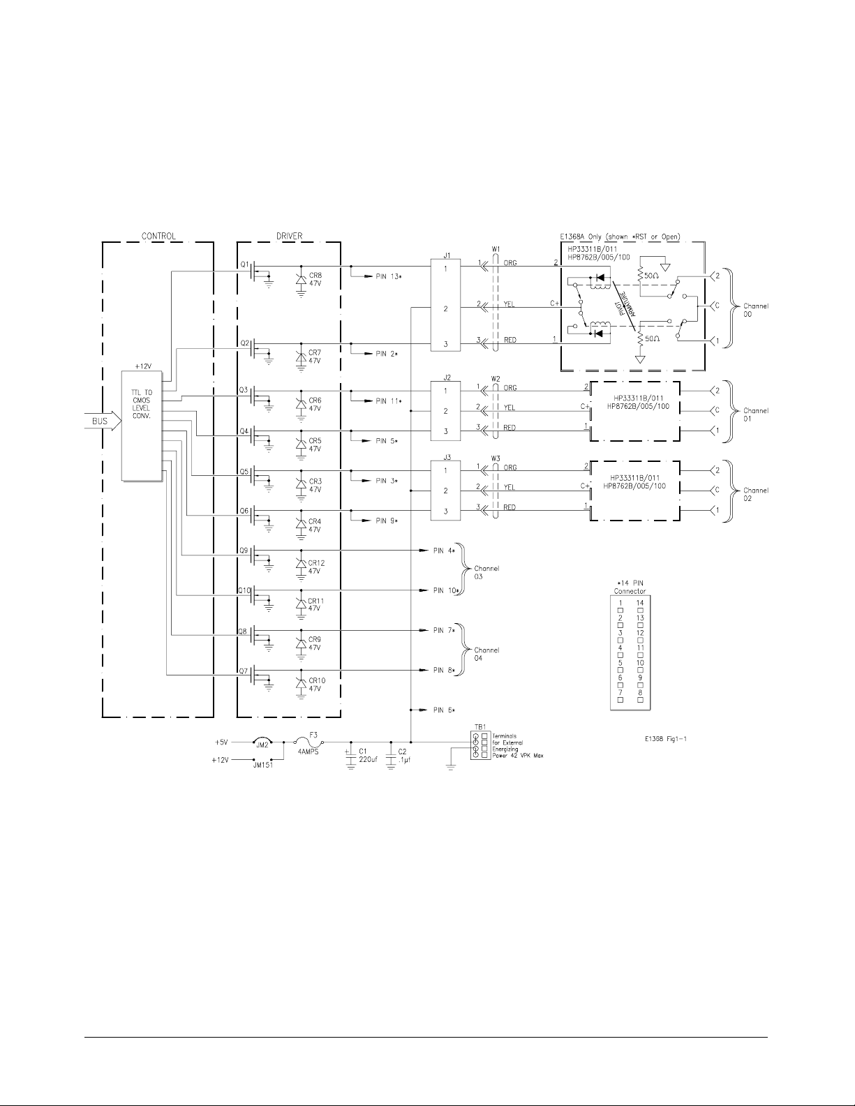
Figure 1-1. HP Microwave Switch Block Diagram
12 Getting Started with the HP E1368A/69A/70A Chapter 1
Page 13

Power Supply
Circuit
Note Check mainframe power availability before using internal voltages.
Caution MAXIMUM VOLTAGE. The maximum voltage that may be
Power to operate the coaxial switches can be supplied internally or
externally, dependent on the type of coaxial switch used.
• Internal voltages of either +5V or +12V can be selected using
jumpers on the board. Th ese voltages are routed through the module
from the mainframe backplane.
• External voltages of up to 42Vpk can be connected using the
EXTernal POWER terminal block.
applied to the EXTernal POWER terminal is 42Vpk. Remove the
F3 fuse when using external switch power.
MAXIMUM CURRENT. The maximum current that the control
circuit can accommodate is 1 amp per switch. Maximum
current also depends on the output capacity of the mainframe
or power supply used.
HP E1368A
Switches
The HP E1368A Microwave Switch module contains three HP 33311B
Option 011 (8672B Option 005 and 100) microwave Switches:
• Broad bandwidth (DC - 18 GHz).
• High isolation (>90 dB to 18 GHz).
• Excellent repeatability (typically 0.03 dB after 1,000,000 switchings).
• Internal 50Ω terminations.
These coaxial switches allow +5V coil voltage electrical chara cteristics
(drive volta ge) operation inst ead of t he standa rd +24V. This is necess ary
since the Microwave Switch module provides only +5V or +12V for driving
microwave switches.
These coaxial switches are break-before-make switches controlled by a
latching solenoid. Internal coil contacts open and remove coil voltage after
a switching operation to minimize the amount of heat dissipated near the
swit ch contact s.
When a coil is energized and a switching operation occurs, a pivot armature
in the microwave switch also operates both sets of contacts, either closing
the switch or connecting it to the 50Ω termination.
Chapter 1 Getting Started with the HP E1368A/69A/70A 13
Page 14

Instrument Definition
HP plug-in modules installed in an HP mainframe or used with an HP
command module are treated as independent instruments each having a
unique secondary HP-IB address. Each instrument is also assigned a
dedicated error queue, input and output buffers, status registers and, if
applicable, dedicated mainframe/command module memory space for
readings or data. An instrument may be composed of a single plug-in
module (such as a counter) or multiple plug-in modules (for a switchbox or
scannin g voltme ter instrument).
Programming the Microwave Switch
To program the modules using SCPI commands, you must select the
controller Modu le language, int erfac e address, and a ppr opria te commands.
See the HP 75000 Series B Install atio n and Getti ng Sta rted Guid e or the
appropriate HP Command Module Ma nual for interface addressing and
controller language informat io n of Microwave Switch modul es in a
switchb ox or sca nning voltmeter configurat ion.
Note This discussion applies to SCPI programming. See Appendix B
(Microwave Switch Registers) for details on Microwave Switch modules
registers.
Selecting Channels: To address specific channels within a Microwave
Switch module in a switchbox, you must:
• send the appropr ia te SCPI command string to the s witchbox (e.g.,
CLOSe, OPEN, etc.). For the Microwave Switch modules, use the
CLOSe command to connect the 2-port to the C-port. Use the OPEN
command to connect the 1-port to the C-port.
• sp ecify t he card numb er (01-99)
• specify the channel number (00-04)
channel_list
=
}
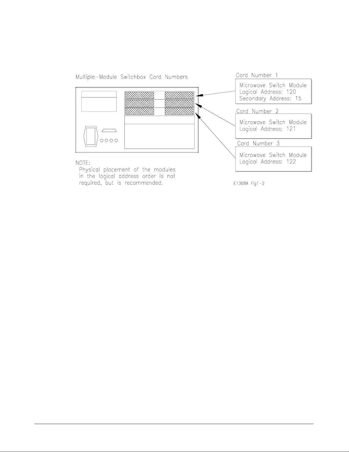
Card Numbers The card number identifies the module within a switchbox. The Microwave
Switch card number depends on the switchbox configuration (single-module
or multiple-module) set for the switches.
• Single-module. For a single-module switchbox, the card number is
always 01.
• M ultiple-module. For a multiple-module switchbox, the switch
module with the lowest log ical addr ess is always card nu mb er 01.
The card number with the next successive logical address is 02, and
so on. Figure 1-2 i llustr at es the card numbers and logical addre s s es
of a typical multiple-module switchbox.
14 Getting Started with the HP E1368A/69A/70A Chapter 1
Page 15
The logical addres s es no ted in Figure 1-2 app ly t o modules installed in an
HP 75000 Series B M a inframe (HP Model Number E1300/E1301) or in a
mainframe with a n HP E1405/E1406 Command Module. See the HP 75000
Series B Installation an d Getting Start ed Guide or the appropriate HP
Command Module Manual for mor e infor mation on switchboxes and log ical
addressing.
Figure 1-2. Card Numbers for Multip le-M odu le Swi tch box es
Channel Numbers The channel number identifies the channel within a module. The
Microwave Switch channel number depends on the module (HP E1368A
Microwave Switch or HP E1369A Microwave Switch Driv er).
• HP E1368A. Valid channel numbers ar e 00-04 (c hannels 03 a n d 04
are valid but not connected).
• HP E1369A. Valid c hannel nu mbers are 00-04.
• HP E1370A. Valid c hannel numbers are 00-04.
Channel Address For th e Microwave Switch Modules, the channel address (channel_list) is in
the form:
• (@ccnn) for a single channel
• (@ccnn, ccnn) for multiple channels
• (@ccnn:ccnn) for sequential channels
• (@ccnn:ccnn, ccnn:ccnn) for groups of sequential channels
• or any combination of the above
whe re "cc" is the card n umber an d "nn" is t he chan n e l number . F o r
example, command str ing to close channel 02 of card number 1 is:
CLOSe (@0102)
Since "cc" (the card number) must be sent, it becomes part of the channel
number. Also, you can ignore leading zeros in the card nu mb ers. Thus, to
close channel 02, s end "102" instead of "0102". To close th e abov e channel,
execute:
CLOSe (@102)
Chapter 1 Getting Started with the HP E1368A/69A/70A 15
Page 16

SCPI Command
Format Used in
This Manual
Initial Operation
You can send SCPI commands in either s hort or long form. R efer to
Chapter 4 for more informati on. A long form examp le is:
CLOSe (@102)
The same co mmand shown without the lower case letters is the short form.
The co mmand then becomes:
CLOS (@102)
Some commands in this manual are shown with brackets ([ ]). These are
implied or optional c ommands that you do not have to ex ecute. For
example, the
manual as:
[ROUT:]CLOS (@102)
Thus, to execute these commands, simply enter:
CLOS (@102)
Use the following program example to verify initial Microwave Switch
operation by closin g a channel and queryi ng channel c losure. Th e example
first resets the switchbox and then closes chann el 02 of a single Microwave
Switch module (card number 1) in the switchbox. The program next queries
the channel closure stat e. A returne d "1" shows that the command t o c lose
the channel has been sent to the switchbox. A returned "0" shows that the
command to close t he channel has not b een sent to the switch box.
ROUTe command is an implied command and is shown in this
The comput er used in the exa mple is an HP Series 200/300 comput er with
HP BASIC as t he pro gr am la ngu a g e. The comput er interfaces to the
mainframe using the Hewlett-Packard Interfac e Bus (HP-IB).* The HP-IB
interface s elect co de is 7, the HP-IB prima ry addr ess is 09 , and the HP-IB
secondary address is 15. Ref er to the HP 75000 Series B Installation and
Getting Started Guide for add ressing in fo rmation.
Example: Reset the switchbox and close channel 02.
10 OUTPUT 70915;"*RST" !Resets the module; opens al l
20 OUTPUT 70915;"CLOS (@102)" !Close channel 02.
30 OUTPUT 70915;"CLOS? (@102)" !Query ch annel 02.
40 ENTER 70915;Value !Enter r e su l ts in to v alue.
50 PRINT Val ue !Display resul ts (should return
60 END !Terminate prog ram.
* HP-IB is Hewlett-Packard’s impl emen ta tion of IEEE Std 488. 1-1984
channels.
"1").
16 Getting Started with the HP E1368A/69A/70A Chapter 1
Page 17

Configuring the HP E1368A/69A/70A
Using This Chapter
This chapter shows how to connect ext ernal wiring to the Microwave
Switch Modules connectors, and how to configure the module for operation.
• Setting the Add ress Switch . . . . . . . . . . . . . . . . . . . . . . . . . . Page 18
• Selecting the Interrupt Priority . . . . . . . . . . . . . . . . . . . . . . . Page 19
• Installing Switches on the HP E1369A . . . . . . . . . . . . . . . . . Page 20
• Installing a Switch or Attenuator on the
HP E1370A. . . . . . . . . . . . . . . . . . . . . . . . . . . . . . . . . . . . . Page 26
Warnings and Cautions
Chapter 2
Modules
Warning SHOCK HAZARD. Only service-trained personnel who are
aware of the hazards involved should install, remove, or
configure the Microwave Switch modules. Before you remove
any installed module, disconnect AC power from the mainframe
and from other modules that may be connected to the
Microwave Sw itch.
Caution MAXIMUM POWER. The maximum power that may be applied
to any SMA input connector is 1 W (CW). The maximum voltage
that may be applied to the EXTERNAL B+ terminal is 42Vpk.
CONNECTING +5V/+12V. For t he Microwave Switch, the
mainframe backplane +5V is fused at 4A, and the +12V line at
4A. The total current drawn by all coaxial switches connected
to the Microwave Switch module must not exceed the fuse
rating of the supplies (mainframe and/or external) used.
STATIC ELECTRICITY. Static electricity is a major cause of
component failure. To prevent damage to the electrical
components in the Microwave Switch modules, observe
anti-static techniques whenever removing a module from the
mainframe or whenever working on a module.
Chapter 2 Configuring the HP E1368A/69A/70A Modules 17
Page 18

Setting the Address Switch
The logical address switch (LADDR) factory setting is 120. You may have
changed the setting during module installation. Valid address values are
from 0 to 255. If the Microwave Switch modules are used in a HP
E1300/E1301 Mainframe, refer to the HP 75000 Series B System
Installation an d Getting Start ed Guide for addressing information.
Otherwise, us e Figure 2-1 to c hange the setting.
Note The address switc h selec t ed valu e must b e a multiple of 8 if the module is
the first modu le in a " switchb ox" u sed in a VXIbus ma inframe, and being
inst ru cted by SCPI comman ds.
Figure 2-1. Logical Address Selecti on
18 Configuring the HP E1368A/69A/70A Modules Chapter 2
Page 19
Selecting the Interrupt Priority
The Microwave Switch modules generate interrupts after a channel has been
closed or opened. The se interrupts ar e sent to, and ac knowledgments are
received from, the slot 0 module via the VXIbus backplane interrupt lines.
For most applications where the Microwave Switch modules are installed in
an HP 75000 Series B or Series C mainframe, these jumpers do not have to
be moved. This is because the VXIbus interrupt lines have the same
priority a nd interrupt priority is established by installing modules in slots
numerically closest to the slot 0 m odule. T hus, slot 1 (intern al to the Series
B mainframe) has a higher priority than slot 2 (also internal), s lot 2 has a
higher priority than slot 3, etc.
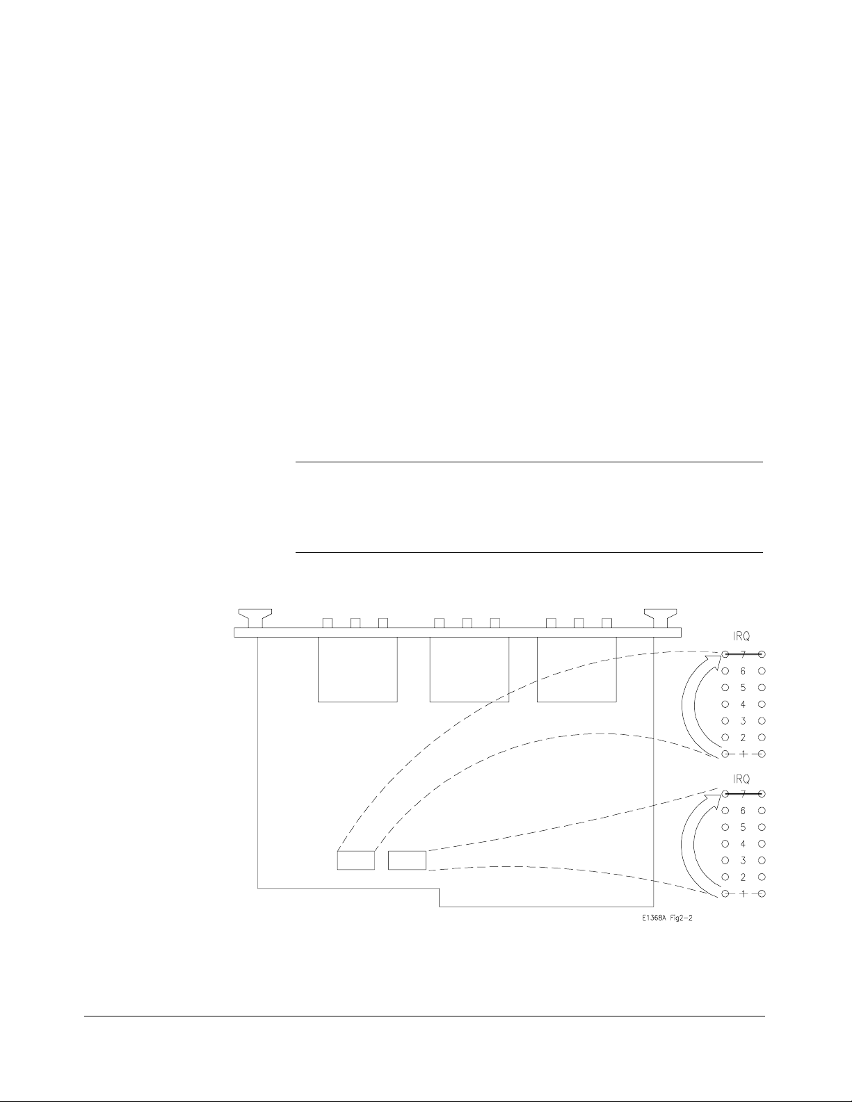
Refer to Figure 2-2 t o c hange t he int errupt pri ority. You can select seven
different interrupt priority levels. Level 1 is the lowest priority an d Level 7
is the highest priority. The Module’s factory setting is Level 1. To change,
clip out and remove two jumpers from the old priority location. Install and
solder two n ew jumpers in th e new priorit y location (Figure 2-2 shows a
priority change from 1 to 7).
Note Both jumper locations must have the same interrupt priority level jumper
NOTE:
In this example, the priority
jumpers are moved f rom
position 1 t o posi ti on 7
(lowest priority to highest
priority).
installed. Changing the priority level ju mpers is n ot rec ommen ded. Do not
change unless specifically instructed to do so.
Figure 2-2. Interrupt Priority Selecti on
Chapter 2 Configuring the HP E1368A/69A/70A Modules 19
Page 20

Installing Switches on the HP E1369A
Because the HP E1369A Microwave Switch module s do not have
Microwave Switches installed by the factory, it is necessary to install or
connect s witches before operating. Determine t he number of switches, and
whether the switches are to be installed on, or connected to, the mo dule and
proceed as instructed below.
Installing Switches
on the Module
Installation described for up to three coaxial switches (channels 00-02) is
below. Figure 2-3 s hows the wiring d iagram and mount ing hole c enters for
each switch installed.
HP SWITCHES. The following 5V HP 333XX series and HP 876X series
switches will function in the HP E1369A Microwave Switch module.
Note The corresponding HP 876X and 33 3XX series switc hes s hown in the table
below are electrically and physically identical. The HP 8761, 8766 (33363),
8767 (33364),876 8 (33365 ),8769 (3336 6) series c oaxial switches will not
function in the HP E1369A Microwave Switch module beca u se the switch
coils are not split (separate for e ach conta ct).
HP Part Number Frequency Characteristic
33311B/011 or 8762B/005/100
33311C/011 or 8762C/005/100
33312B/011 or 8763B/005/100
33312C/011 or 8763C/005/100
33313B/011 or 8764B/005/100
33313C/011 or 8764C/005/100
33314A/011 or 8765A/005/100
33314B/011 or 8765B/005/100
33314C/011 or 8765C/005/100
DC to 18 GHz
DC to 26.5 GHz
DC to 18 GHz
DC to 26.5 GHz
DC to 18 GHz
DC to 26.5 GHz
DC to 4 GHz
DC to 20 GHz
DC to 26.5 GHz
Impedance
50
Ω
50Ω
50Ω
50Ω
50Ω
50Ω
50Ω
50Ω
50Ω
Ports Internal 50Ω
3
3
4
4
5
5
3
3
3
Termination
All ports
All ports
One port
One port
No ports
No ports
No ports
No ports
No ports
Auto Co i l
Interrupt
Yes
Yes
Yes
Yes
Yes
Yes
No
No
No
MTG
Hole
C
C
D
D
D
D
B
B
B
NON-HP SWITCHES . K&L Microwave Inc., Dynatech Microwave
Technology Inc., and RLC Electronics Inc. currently manufacture split coil
coaxial switches that will physically mount in the HP E1369A Microwave
Switch module rear panel. All switches mount using the "A" hole centers
(see Figure 2-3). When select ing switches, refer to the diagram shown in
Figure 1-1 to verify that the switch will electrically function in the HP
E1369A Microwave Switch module. R emember, switches must have split
coil operat ion with 42V maximum drive level.
Caution The maximum current that the control circuit can accommodate
is 1 amp per switch. Maximum current also depends on the
output capacity of the mainframe or power supply used.
20 Configuring the HP E1368A/69A/70A Modules Chapter 2
Page 21

After selec t ing the coaxial switch, install as follows:
1. Position the coaxial switch behind the channel 00 panel cut-out.
Secure to rear panel using two M2.5 x .45 metric screws
(P/N 0515-1373).
2. Route the 3-wire cable (P/N E1368-61601) from J1 to the coaxial
switch terminals. Solder the "RED" wire to pin 1. Solder the "YEL"
wire to pin C. Solder the "ORN" wire to pin 2.
Note On the HP 33314 (8765) series switches, it is necessary to jumper the two C
terminals so that both connect to the "YEL" wire.
3. Repeat steps 1 and 2 with remaining coaxial switches. The channel
01 switch connects to J2 connector, and channel 02 c onnects to J3.
Caution Do not leave an unused 3-wire cable installed in J1, J2, or J3 if
a coaxial switch is not installed. The center conductor of all
three connectors is connected to the switch operating voltage
at all times. Contact of this conductor to ground may cause the
fuse to open, or damage to the power supply or module.
4. Route the 3-wire cables behind the coaxial switches as not to catch or
snag on any o b jects dur ing module installation in the mainfra me or
control module (see Figure 2-3).
5. Select correct switch o p erati ng voltages (see “Selecting Switch
Power” later in t his ch a pter).
Chapter 2 Configuring the HP E1368A/69A/70A Modules 21
Page 22
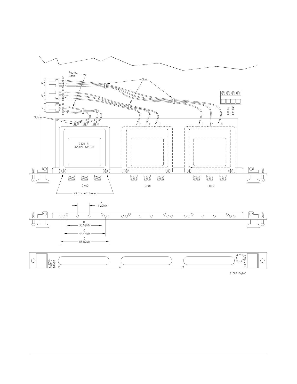
Figure 2-3. Microwave Switch Installation
22 Configuring the HP E1368A/69A/70A Modules Chapter 2
Page 23
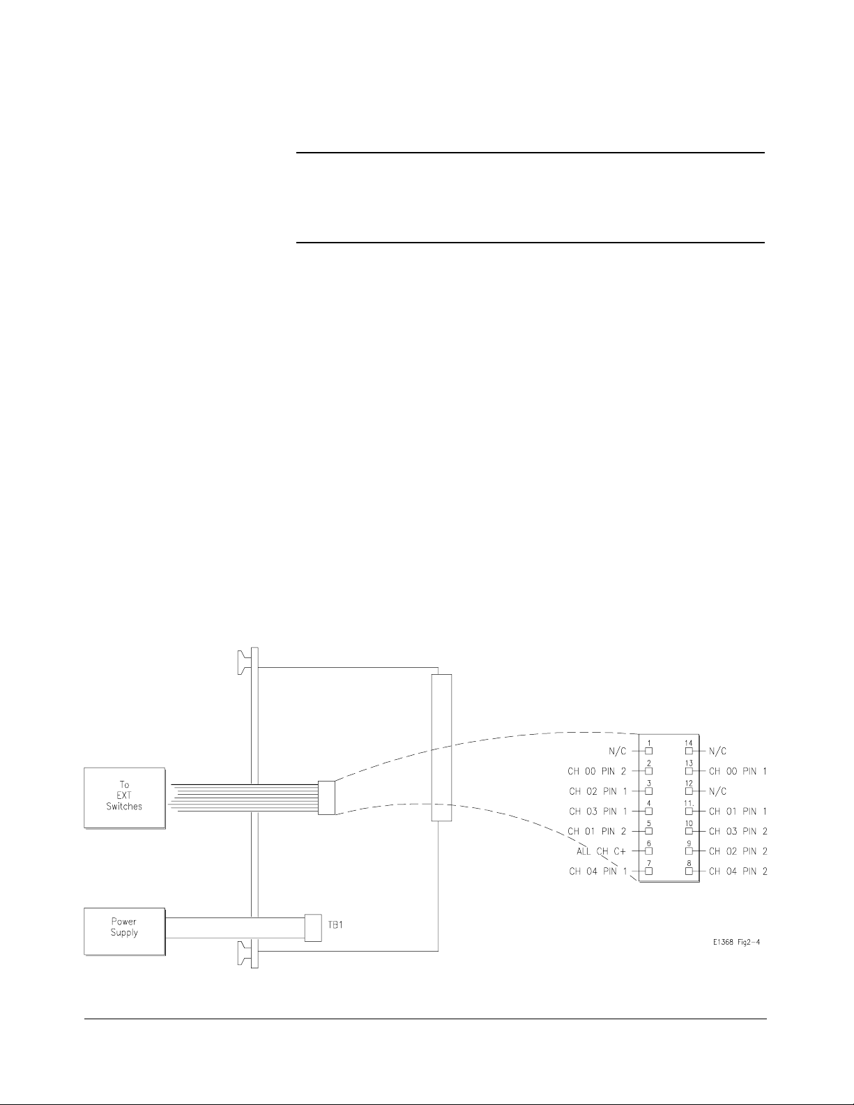
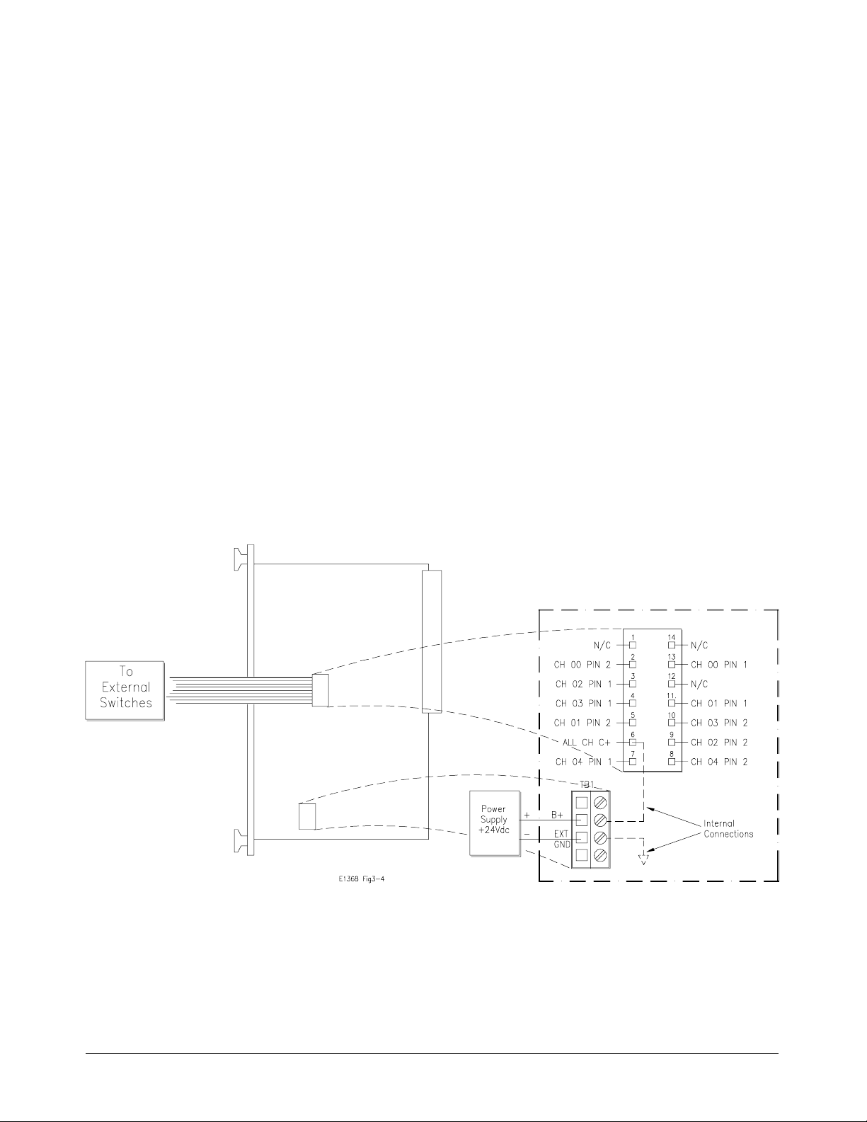
Connecting
Switches Ext ernal
to the Module
Caution The maximum current that the control circuit can accommodate
Connection of up to five coaxial switc hes (channels 00-04) is described
below. Figure 2-4 shows the wiring diagram for each switch c onnected.
is 1 amp per switch. Maximum current also depends on the
output capacity of the mainframe or power supply used.
After selecting the coaxial switches, c onnect to the 14-pin connector as
follows:
1. Route an 11-wire cable (not-supplied) from the 14-pin connector on
the Microwave Switch module to the switch location. Route the
wires through the panel holes as not to catch or snag on any objects
during module installation in the mainframe or control module.
2. Connect all C+ terminals on all the coaxial switches to pin 6.
3. Connect CH00 through CH04 s witch terminals as required.
CH00 1 terminal to pin 13, and the 2 t erminal to pin 2.
CH01 1 terminal to pin 11, and the 2 t erminal to pin 5.
CH02 1 terminal to pin 3, and t he 2 terminal to pin 9.
CH03 1 terminal to pin 4, and t he 2 terminal to pin 10.
CH04 1 terminal to pin 7, and t he 2 terminal to pin 8.
4. Select correct switch o p erati ng voltages (see “Selecting Switch
Power” later in t his ch a pter).
Figure 2-4. Microwave Switch Connecti on
Chapter 2 Configuring the HP E1368A/69A/70A Modules 23
Page 24

Selecting Switch
Power
After the coaxial switches have been installed (refer to “Install ing Switches
on the HP E1369A” earlier in this chapter), the correct operating voltage
mu s t be selected. See installed swit ch specifications .
The Microwave Switch modules are capabl e of providing +5V (set at
factory) or +12V using the mainframe power supply, or external voltages of
up to 42Vpk can be connected. Determine the required operating vo ltage
and proceed as instr ucted below. Refer to Figure 2-5 as required.
Caution MAXIMUM CURRENT. The maximum current that the control
circuit can accommodate is 1 amp per switch. Maximum
current also depend s on the output capacity of the mainframe
or power supply used.
Internal Power Verify that the F3 fuse (P/N 2110-0712) is installed. Position jump ers as
instructed:
• For 5V, jump er JM2 installed, and jumper JM151 remo ved.
• For 12V, jumper JM151 installed, and jumper JM2 removed.
External Power Verify that the F3 fuse (P/N 2110-0712) is removed (unsolder if necessary).
Connect the positive lead to EXT B+ on TB1, and the negative lead to EXT
GND on TB1. Connect leads to external power supply. Observe polarity.
Caution MAXIMUM VOLTAGE. The maximum voltage that may be
applied to the EXTernal POWER terminal is 42Vpk.
• Maximum wire size is No. 16 AWG. Wire ends should be stripped 6
mm (~ 0.25 in.) and tinned to prevent single strands from shorting
adjac ent ter minals .
• It is recommended that each channel wire be identified (color coded
or marked) as the connection is not visible when the Microwave
Switch module is installed.
• Verify that wires make good connections on screw termina ls.
24 Configuring the HP E1368A/69A/70A Modules Chapter 2
Page 25
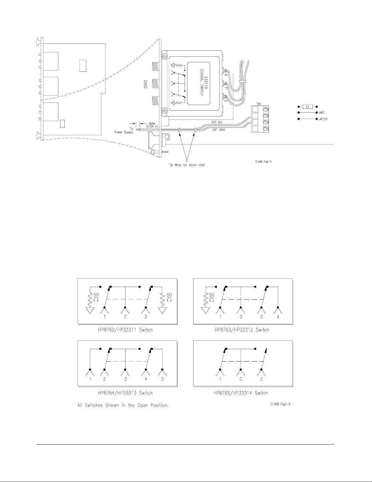
Figure 2-5. Selecting Switch Voltage
Connecting Field
Wiring
Figure 2-6 shows the int ernal swit ch diagram f or t he various HP 3-por t,
4-port, and 5-port coaxial switches. All switches are shown in the "OPEN"
positio n. To minimize loss at high frequenc ies, u se the following guidelines
when maki ng c onnect ions.
Cabling Guideli nes For frequencies to 18 GHz, use a goo d qualit y flexible typ e ca ble and SMA
connectors. For frequencies 18 GHz, use semi-rigid type cable and APC 3.5
connectors.
Figure 2-6. Switch Configu ratio ns
Chapter 2 Configuring the HP E1368A/69A/70A Modules 25
Page 26

Installing a Switch or Attenuator on the HP E1370A
Microwave Switch/Attenuator Card
Because the HP E1370A Microwave Switch/Attenuator modules do not
have a Microwave Switch of Attenuator installed by t he fac tory, it is
necessary to inst a l l or connect a switch or attenuator bef ore operating.
Determine wh e t her the switch or a t t enuator is to b e installed on, or
connected to, t he module and proceed as instructed below.
Installing a Switch
or Att enuator on
the Module
Installation of a Microwave Switch of Attenuator is described below.
Figure 2-7 shows the wiring diagram and mou nti ng hol e centers for the
switch of att enu at or i nstalled.
HP SWITCHES. The following 5V HP 3336xx series s wit ches will
function in the HP E1370A Microwave Switch/Attenuator module.
HP Part Number Frequency Ports
33363K
33364K
33365K
33366K
DC to 26.5GHz
DC to 26.5GHz
DC to 26.5GHz
DC to 26.5GHz
Single-Pole, thr ee-throw
Single-Pole, four-throw
Single-Pol e, five-thr ow
Single-Pol e, six-thr ow
Order all of the above with Option 011 (5 volt solenoi d assembl y) and
Option 008 (8 inch ribbon cable).
HP ATTENUATORS. The following 5V HP 3332X Step Attenuators will
function in the HP E1370A Microwave Switch/Attenuator module.
HP Part
Number
Frequency Attenuation Attenuation Step
Size
33320G
33320H
33321G
33321H
33322G
33322H
33323K
DC to 4 GHz
DC to 18 GHz
DC to 4 GHz
DC to 18 GHz
DC to 4 GHz
DC to 18 GHz
DC to 26.5 GHz
0 - 11 dB
0 - 11 dB
0 - 70 dB
0 - 70 dB
0 - 110 dB
0 - 110 dB
0 - 90 dB
1 dB
1 dB
10 dB
10 dB
10 dB
10 dB
10 dB
Order all of the above with Option 011 (5 volt solenoi d operation) and
Option 008 (8 inch ribbon cable).
26 Configuring the HP E1368A/69A/70A Modules Chapter 2
Page 27

After select ing the coaxial switch or att enuator, install as follows:
1. Position the coaxial switch or attenuator behind the panel cut-out.
Use two M3.0 x 8mm (P/N 0515-0372) metric screws to secure the
rear panel. Use two 4-40 x .25 inch screws (P/N 2200-0521) to
secure the attenuator to the rear panel.
2. Route the ribbon cable from the Microwave Switch or Attenuator to
the 14-pin connector on the PC board.
3. Install the c orrect f il ler panel on t h e switch so that minimal air can
flow through the slot.
Figure 2-7. Microw ave Swi tch / Attenu ato r Instal lati o n
Chapter 2 Configuring the HP E1368A/69A/70A Modules 27
Page 28
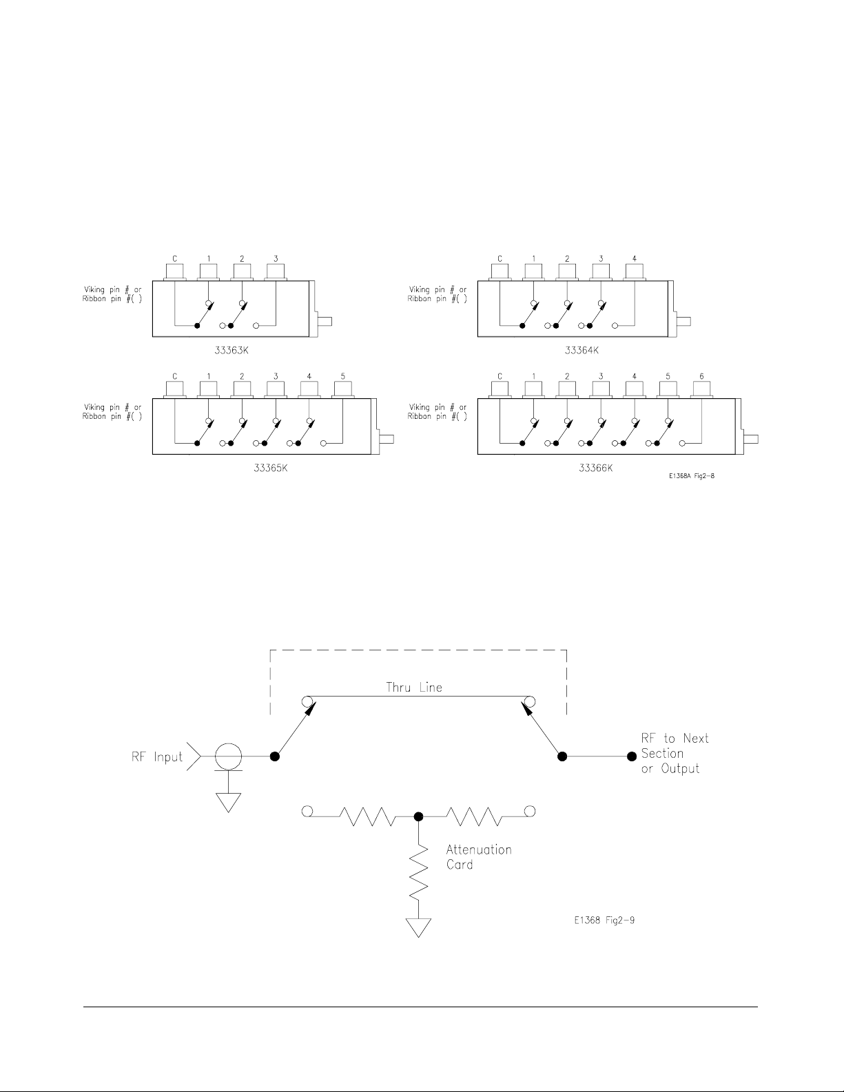
Connecting Field
Wiring
Figure 2-8 shows the int ernal swit ch diagram f or t he various HP
single-pole, multi-throw switches. All switches are shown in the "OPEN"
positio n. To minimize loss at high frequenc ies, u se the following guidelines
when maki ng c onnect ions.
• For frequencies up to 18 GHz, use a good quality flexible type cable
and SMA connectors.
• For frequenci es >18 GHz, use semi-rigid type cable and APC 3.5
connectors.
Figure 2-8. Internal Switch Diagrams
Figure 2-9 shows t he internal schematic of a single attenuator section.
Figure 2-9. Attenuat or
28 Configuring the HP E1368A/69A/70A Modules Chapter 2
Page 29

Using the HP E1368A/69A/70A Modules
Using This Chapter
This chapter uses typical examples to show how to use the Microwave
Switch modules. This chapter contains the following sections:
• Microwave Switch Commands . . . . . . . . . . . . . . . . . . . . . . . Page 29
• Reset Conditions . . . . . . . . . . . . . . . . . . . . . . . . . . . . . . . . . . Page 30
• Switching Channels . . . . . . . . . . . . . . . . . . . . . . . . . . . . . . . . Page 31
• Scanning Channels. . . . . . . . . . . . . . . . . . . . . . . . . . . . . . . . . Page 39
• Recalling and Savin g Stat es. . . . . . . . . . . . . . . . . . . . . . . . . . Page 43
• Detectin g Error Conditions . . . . . . . . . . . . . . . . . . . . . . . . . . Page 43
• Synchronizing the Microwave Switch. . . . . . . . . . . . . . . . . . Page 45
• Queryin g the M i crowave Swi tch. . . . . . . . . . . . . . . . . . . . . . Page 46
Microwave Switch Commands
Chapter 3
Table 3-1. Microwave Switch Commands in Chapter 3
Command Command Description
INIT[:IMM] Starts the scan sequence and closes the first channel in
the
channel list.
OUTP[:STAT] ON Enables the HP E1300A/E1301A "Trig Out" port to
output pulses.
[ROUT:]CLOS <
[ROUT:]CLOS? <
[ROUT:]OPEN <
[ROUT:]SCAN <
TRIG:SOUR BUS|EXT|HOLD|IMM S e lect the trigger source to advance the scan.
*CLS Clears all switchbox Status Registers.
*ESE Enables the Event Status Register.
*RST Sets the hardware and software to a known state.
*SRE Enabl es the Status Register.
channel_list> Close the channels in the channel list.
channel_list> Query the state of the channels in the channel list.
channel_list> Open t he channels in the channel list.
channel_list> Closes the channels in the cha nnel lis t one at a time.
Chapter 3 Using the HP E1368A/69A/70A Modules 29
Page 30

Reset Conditions
When the Microwave Switch is switched on or *RST (reset), a ll channels
are set to open (refer to Figure 2-6), and the current channel list for scanning
is invalidat ed. Table 3-2 l ists the parame t ers and defau lt values for the
functions described in Chapter 3.
Table 3-2. *RST (Reset) Default Conditions and Values
Parameter Default Description
ARM:COUNt 1 Number of scanning cycles is one.
TRIGger:SOURce IMM Will advance scanning cycles automatically.
INITiate: CO NTi nuous OFF Number of scanning cycles is determined by
ARM:COUNt.
OUTPut:STATe OFF "Trig Out" port on mainframe is disabled.
SCAN:MODE NONE Not used by the Microwave Switch module s.
SCAN:PORT NONE Not used by the Microwave Switch modul e s.
Caution When the Microwave Switch is powered up, signals connected
to the normally closed (N/C) port will also be connected to the
output port (refer to Figure 2-6).
Note The Microwave Swit c h modules do not sup p ort 4- wire r esistance scann ing
(FRES).
30 Using the HP E1368A/69A/70A Modules Chapter 3
Page 31

Switching Channels
For general purpose switch operation, you can connect or disconnect a
signal b y opening or closing a specific channel.
• Use CLOS <channel_list> to close coaxial swit ch channel (s), and
OPEN <
Figure 2-6 for the various HP coaxia l switch configurations.
<channel_list > has the form (@ccnn) where cc = card number
(01-99) and nn = channel number (00-04).
channel_list> to open coaxial switch c hannel(s). Refer to
Example: Single
Channel Switching
This exam ple illustrates closing and op ening channel 00 in a HP E1368A
Microwave Switch module. Figure 3-1 shows how the channel is
configured.
To close channel 00, execu te:
CLOS (@100) Connect channe l 00 s witch port 2
to port C, and te rminate port 1 int o
50; 1 is the card number and 00 is
the channel number.
To open channel 00, execute:
OPEN (@100) Connect channe l 00 s witch port 1
to port C, and te rminate port 2 int o
50; 1 is the card number and 00 is
the channel number.
Figure 3-1. Example: HP E1368A Single Channel Switching
Chapter 3 Using the HP E1368A/69A/70A Modules 31
Page 32

Example: Single
Channel Switching
using EXTernal
POWER
This example illustra tes closing and op ening coaxia l switch channe l 01 in a
HP E1369A Microwave Switch Driver module. For the example, the type
of switch installed in the HP E1369A is a HP 33311 B (8762 B), wit h 24Vd c
drive requirements. Figure 3-2 shows how to connect an external power
supply to the EXTerna l POWER terminals to provide the nec essary 2 4 Vdc
drive for the coaxial switch.
To close channel 01, execu te:
CLOS (@101) Connect channe l 01 s witch port 2
to port C, and te rminate port 1 int o
50; 1 is the card number and 01 is
the channel number.
To open channel 01, execute:
OPEN (@101) Connect channe l 01 s witch port 1
to port C, and te rminate port 2 int o
50; 1 is the card number and 01 is
the channel number.
Figure 3-2. Examp le: Sing le Chan nel Switch in g usi ng Extern al Po we r
32 Using the HP E1368A/69A/70A Modules Chapter 3
Page 33

Example: Chann el
Switching using the
E1370A and the
33366K Microwave
Switch
This example illustra tes how to make connections to different ports on the
HP E1370A Microwave Switch/Attenuator Driver and the HP 33366K
Single-pole, Six-throw Microwave Switch. Figure 3-3 shows how the b oard
and switch are configured.
Figure 3-3. Example: HP E1370A Multiple Channel Switching
To connect C to Port 1, execute:
CLOS (@103)
To connect C to Port 2, execute:
OPEN (@103) Opens the connec t ion to port 1.
CLOS (@101) Closes the co nne c ti on to port 2.
To connect C to Port 3, execute:
OPEN (@101) Opens the connec t ion to port 2.
CLOS (@102) Closes the co nne c ti on to port 3.
To connect C to Port 2, execute:
OPEN (@102) Opens the connec t ion to port 3.
CLOS (@100) Closes the co nne c ti on to port 4.
To connect C to Port 2, execute:
OPEN (@100) Opens the connec t ion to port 4.
CLOS (@104) Closes the co nne c ti on to port 5.
Chapter 3 Using the HP E1368A/69A/70A Modules 33
Page 34

Note: Because of the specific ribbon cable configurations, the channel number
does not directly correspond to the same port number. Tabl e 3-3 maps t he
port numb ers t o the corresponding channel numbers for all of the
HP333XXK Microwa ve S witches. For example, to con nect C to port 3 on
the HP3365K Single-pole, Four-throw Switch, channel 2 wou ld ha ve t o b e
closed.
Table 3-3. Map of Channel Nu mbers to Port Numbe rs.
Switch
Part
Number
33363K 0 1
33364K 1 2 0
33365K 3 1 2 0
33366K 3 1204
12345
C (Connected to Port )
34 Using the HP E1368A/69A/70A Modules Chapter 3
Page 35
Example: Multiple
Channel Switching
using EXTernal
POWER
This exam ple illustrates closing and op ening coaxia l switch channels 00
through 04 in a HP E1369A Microwave Switch Driver module. For the
example, the switches are not installed on the HP E1369A card, and have
24Vdc drive requirements (HP 33311B or 8762B). Figure 3-4 sho ws how
to connect an external power supply to the EXTernal POWER termi nals to
provide the necessary 24Vd c drive for the coaxial switches, and how t o
connect the 14-pin cable to the external switches.
To close channels 00 through 04, execute:
CLOS (@100:104) Connect channels 00, 01, 02, 03,
and 04 switch port 2 to port C, and
terminate port 1 into 50; 1 is the
card number and 00-04 are the
channel numbers.
To open channel 00 through 04, execute:
OPEN (@100:104) Connect channels 00, 01, 02, 03,
and 04 switch port 1 to port C, and
terminate port 2 into 50; 1 is the
card number and 00-04 are the
channel numbers.
Figure 3-4. Example: Mult iple External Chan nel
Switching using External Power
Chapter 3 Using the HP E1368A/69A/70A Modules 35
Page 36
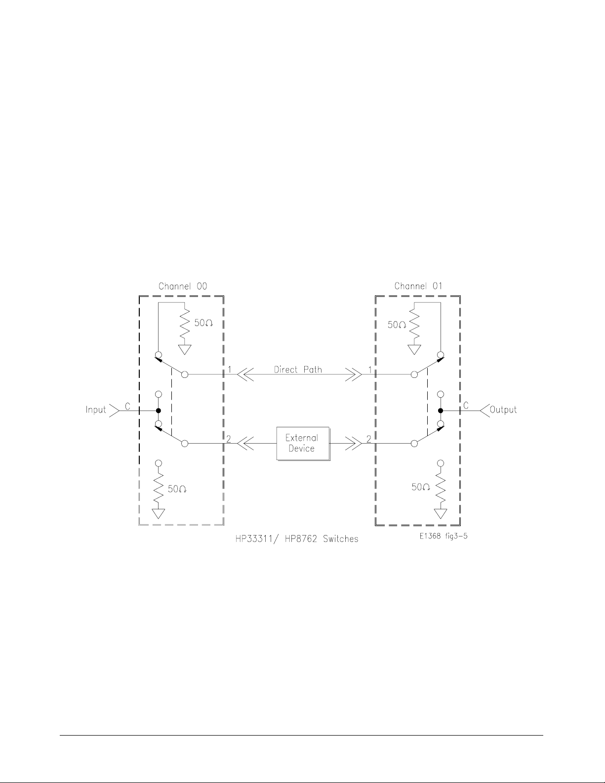
Example: Transfer
Switch Using Two
3-Port Switches
This example shows how to configure the HP E1368A Microwave Switch
to either route a signal directly to the output, or route it through an external
device before being output. For the example, two switches (channels 00
and 01) will be used. F igure 3-5 shows how to connect channels 00 and 01.
To ro ute the signal directly, execu te:
OPEN (@100,101) Connects port C to port 1 of both
channels and ro u tes the signal
direct ly to the outp ut.
To route the signal through the external device, execute:
CLOS (@100,101) Connects port C to port 2 of both
channels and ro u tes the signal
through the external device to the
output.
Figure 3-5. Example: T ransf er Switch (two chan n el)
36 Using the HP E1368A/69A/70A Modules Chapter 3
Page 37

Example: Transfer
Switch Using One
5-Port Switch
Comments The one channel 5-port transfer switch example does not terminate the
This example shows how to configure the HP E1369A Microwave Switch
Driver with a 5-port switc h (HP 33313 or 8764 ) installed, to either route a
signal directly to th e output, or r oute it through an external device before
being output. For the example, one switch (channel 02) will be used.
Figure 3-6 shows how to connect channel 02.
To ro ute the signal directly, execu te:
OPEN (@102) Connects port 3 to port 2 and
routes the signal direct ly to the
output.
To route the signal through the external device, execute:
CLOS (@102) Connects port 1 to port 2 and port
3 to port 4 routi ng th e si gnal
through the external device to the
output.
External Device into 50Ω when not connected to the input.
Figure 3-6. Example: Transfer Switch (one chan nel)
Chapter 3 Using the HP E1368A/69A/70A Modules 37
Page 38

Example: 4 x 1
Multiplexer
This example shows how to configure the HP E1368A Microwave Switch
to select one of four signals for output. For the example, all three switches
(channels 00 through 02) will be used. Figure 3-6 shows how to connect
channels 00 through 02.
To route signal "A" to the output, execute:
OPEN (@100,102) Connects signal "A" (chann el 00
port 1) to the output (channel 02
port C).
To route sig nal "B" to the output , execute:
CLOS (@100);OPEN ( @102) Connects signal "B" (channel 00
port 2) to the output (channel 02
port C). To route signal "C" to the
output, execute:
OPEN (@101);CLOS (@102) Con ne cts sign al "C " (channe l 01
port 1) to the output (channel 02
port C).
To route signal "D" to the output, execute:
CLOS (@101,102) Connects sign al "D " (channe l 01
port 2) to the output (channel 02
port C).
Comments Unused signals are terminated into 50Ω (internal to the switch).
Figure 3-7. Example: 4-Channel Multiplexer
38 Using the HP E1368A/69A/70A Modules Chapter 3
Page 39

Scanning Channels
Scanning the Microwave Switch module channels consists of closing a set
of channels (connecting the 2 port to the C port) one channel at a time.
Single scan, multiple scans (2 t o 32767), or continuous sca nning modes are
available.
TRIGger:SOURc e command specifies the source to advance the scan.
The
OUTPut comman d can b e us ed to enable th e HP E1300/ E1301 or HP
The
E1405/E1406 "Tr ig Ou t " port. Fi gure 3-8 i llustrates the scanning sequence.
Sets number of Scanni ng Cycles
ARM:COUN <
command .
Selects the Trigger Source
TRIG:SOUR defines the trigger source to adva nce the scan.
TRIG:SOUR? queries the current trigg er so urce . So u r ces are :
BUS = Defines trigger source as a *TRG or HP-IB GET command
executed over the HP-IB. With TRIG:SOUR BUS, the scan list is
advanced for each *TRG o r GET command received.
EXT = TRIG:SOUR EXT sets external triggering. The trigger source is a
(user supplied) input to the Event In BNC. Use a +5 V Negative-going
pulse to trigger.
number> sets 1 to 32767 scanning cycles per INIT
HOLD = Prevents execution of triggers until trigger source is changed.
Can use TRIG command to trigger a switchbox set to TRIG:SOUR HOLD.
IMM = Sets immediate (internal) triggering. The scan list is automatically
advan ce d through the s can li st . This is the default trigg er mo de .
Enables TRIG OUT Port
The Trig Out Port is shared by all instruments in the mainframe. With the
port enabled (OUTP ON), it generates an output trigger each time after a
channel closure for ANY switchbox in the mainframe. The Trig Out port
outputs a +5 V ne gativ e-going pulse.
Selects Continuous Scanning Cycles
Use INIT ON or I NI T 1 to enable continuous cycles. INIT OFF or I NI T 0
is fixed number of scans determ ined by the ARM:C OUN comma nd .
Selects the Channel List for Scanning
channel_list> de fines channels to be scanned using trigger
SCAN <
source by TRIG:SOUR command.
Enables Scanning
Enables scanning for any trigger so urce and closes the first channel in
the
channel list.
Advance s Chan nel List
This command advances the channel list when the trigger source is
TRIG:SOUR BUS or TRIG:SOUR HOLD. Command not usable with
TRIG:SOUR EXT or TRIG:SOUR IMM.
Figure 3-8. Example: Scan ning Command s
Chapter 3 Using the HP E1368A/69A/70A Modules 39
Page 40

Example: Scanning
Channels
This example uses the mainframe’s "Trig Ou t " port to sync hronize
Microwave Switch channel 00 to 02 closures to an external measurement
device (e.g. Frequency Counter, Spectrum Analyzer). For measurem ent
synchronization, the HP E1300A/E1301A "Trig Out" port is conn ected to
the external inst ru me nt’s "EXT Trig In" port.
Figure 3-9 shows how to connect the Microwave S witch module to the
external instrume nt. The mainfr ame and external instr ument are co nnec ted
to the computer’s HP-IB port, and the measurement results are transferred
directly to the computer. For the example, use:
• an HP-IB select cod e of 7, primary address of 09, and secondary
address of 15 for the Microwave Switch
• an HP-IB select code of 7, primary address of 22 for the External
Instr ument
• an HP Series 200/300 C omp u t er with HP B ASIC
Execute:
10 OUTPUT 722;"T RI G E XT; …" !Configure s th e exte rnal
instrument. Appropriate instrument
commands must be added to make
the measurement .
20 OUTPUT 70915;"*RST" !Opens all channels, reset s
Micro wave S witch module to
known state.
30 OUTPUT 70915;"OUT P ON" !Enable "Trig Out" port.
40 OUTPUT 70915;"TRI G:SO UR B US" !Sets trigger source to bus
triggering.
50 OUTPUT 70915;"SCAN (@100:102)"!Define s ch anne l list to scan
channels 00, 01, and 02.
60 OUTPUT 70915;"INIT" !Closes ch anne l 00 and enables the
scan. Causes a trigger output from
mainframe’s "Trig Out" port which
initiates the extern al instrumen t to
make a measurement.
70 FOR I=1 to 3 !Start counti ng loop (3 channe ls).
80 WAIT 1 !Allows external instrument time to
settle and mak e measurement.
90 ENTER 722;A !Enters measure me nt result.
100 PRINT A !Displays measurement resul t.
110 TRIGGER 70915 !Advance scan to chan ne l 01 (then
02).
120 NEXT I !Increme nt the count and re peats
measureme nt process for a total of
three measure me nts (c ha nne ls 00 ,
01, and 02).
130 END !Terminate prog ram.
40 Using the HP E1368A/69A/70A Modules Chapter 3
Page 41

Figure 3-9. Example: Multiple Chan n el Scannin g
Example: Using the
Scan Complete Bit
You can use the Scan Complete Bit (bit 8) in the Op erat ion S tatus Register
of a switchbox to determine when a scanning cycle completes (no other bits
in the register apply to the switchbox). Bit 8 has a decimal value of 256 and
you can read it directly with the
STATu s:OPERation[ :EVENt ]? command in Chapter 4 for an example).
When enabled by the
Bit will b e reported as bit 7 of the Status Register. Us e the HP - IB Serial
Poll or the IEEE 488.2 Commo n Command
Register.
When b it 7 of the Status Register is enabled by the
Comman d to assert an HP-IB Service Request (SRQ), you can int errupt the
comput er wh en the Scan Com p lete Bit is set, after scanning cycle
complet es. This al lows the controller to do ot her operations while t he
scannin g cycle is in progress.
The following exampl e monitors bit 7 in the Status Register to determi ne
when the scanning cycle completes. For the example, use:
STAT:OPER:E NAB 2 5 6 command, the Scan Complete
STAT:OPER? command (r ef er to th e
*STB? to read the Status
*SRE 128 Common
• an HP-IB select code of 7, primary a ddress of 09, a nd secondary
address of 15 for the Microwave Switch
• an HP Series 200/300 Comp u t er with HP B ASIC
Chapter 3 Using the HP E1368A/69A/70A Modules 41
Page 42

Execute:
10 OUTPUT 70915;"*CLS" !Clear all switchbox sta tus
structure.
20 OUTPUT 70915;"STAT:O PER: ENAB 256"!Enable Scan Co mple t e Bit to
set bit 7 in Stat us R eg ist er.
30 OUTPUT 70915;"*SRE 128" !Enable bit 7 of Status Register to
assert SRQ.
40 OUTPUT 70915;"TRI G:SO UR EXT " !Set to external trigger mode.
50 OUTPUT 70915;"SCAN (@100:103)" !Se lec t chann els to be sc anne d.
60 OUTPUT 70915;"INIT" !Start scanning cycle.
70 WHILE NOT BIT (SPOLL(70915),7) !Waiting for scan complete.
80 PRINT “DO OTHER OPERATION HERE”!Enter program lines for
computer to do othe r ope rat ion s.
90 END WHILE
100 PRINT “INTERRUPT GENERA TED” !Program goes to this line after
interrupt is generat ed by a
complete d scanni ng cyc le.
110END !Terminate prog ram.
Comments Channel List Can Be Extended Across Boundaries. For multiple module
switchbox instruments, the channels to be scanned can extend across switch
modules. For example, for a t wo module switchb ox instrument,
(@100:203)
will scan all channels of both Microwave Switch modules.
SCAN
Setting Multiple Continuous Scans. Use
1 to 32767 scans. Use
INITiate:CONTinuous O N t o set continuous scanning.
ARM:COUNt number to set from
42 Using the HP E1368A/69A/70A Modules Chapter 3
Page 43

Recalling and Saving States
This section contains information about saving and recalling switch states.
Storing States The *SAV <numeric_s tate> command saves the current instrument state.
The state number (0-9) is specified in th e
following settings are saved:
• Cha n nel Sta tes (op en o r closed )
• ARM:COUNt
• TRIGger:SOURce
• OUTPut:STA Te
• INITiate:CO NTinuous
• SCAN:MODE (not used)
• SCAN:PORT (not used)
Recalling States The *RCL <numeric_state> comman d reca lls a previously saved state.
Enter the number (0-9) in the
saved state. If
number, the Microwave Switch will configure to the reset values.
*SAV was not previously executed using the selected
<numeric_state> parameter of the desired
<numeric_state> parameter. The
Detecting Error Conditions
This section discusses using the various Microwave Switch registers to
detect if a switching operatio n has generat ed an error. There are two
general approaches to error checking. The simplest, but most time
consuming, is to ask the instrument whether there are errors at every step of
the switch ing process. This is calle d "polling" and is illustrat ed in t he
fol l ow i n g ex am pl e .
05 DIM Err_num$ [256]
10 OUTPUT 70915; “CLOS(@100);:SYST:ERR?”
20 ENTER 70915;Err_num$
30 IF VAL (Err_num$) 0 THEN
40 PRINT “Error”;Err_num$
50 STOP
60 END IF
70 …(program continues)
The other approach involves the use of int errupts. The following program is
a method of checking for errors using int errupts as you program the
Microwave Switch. The program monitors the Microwave Switch’s
Standard Ev ent Status Register for an error conditi on. If no errors occur,
the Microwave Switch functions as programmed. If errors do occur, the
Microwave Switch interrupts the computer, and the error codes and
messages are read from the error queue. This approach requires less
checking, but is more complex.
Chapter 3 Using the HP E1368A/69A/70A Modules 43
Page 44

For the example , use:
• an HP-IB s elect c ode of 7, prima r y a ddr e ss of 09, and secondar y
address of 15 for the Microwave Switch
• an HP Series 200/300 Comp u t er with HP B ASIC
Execute:
10 !Call computer subprogram “Errmsg” if a Micro wave
20 !Switch programming error occur s. Enable the com puter to r espond
30 !to an interrupt from the Microwave Switch.
35 !
40 ON INTR 7 CALL Errmsg
50 ENABLE INTR 7:2
60 !
70 !Unmask the Event Status bit in the Microwave Switch’s Status
80 !Register. Unma sk the Microwave Switch error condit io n s in its
90 !Standard Event Status Register.
95 !
100 OUTPUT 70915;"*S RE 32"
110 OUTPUT 70915;"*E SE 60"
120 !
130 !At this point, the Microwave Switch is programmed for the intended
140 !application.
145 !
150 OUTPUT 70915;" . . .
160 OUTPUT 70915;" . . .
170 ENTER 70915; . . .
180 PRINT . . .
190 END
200 !
210 !When an error occurs, clear the Microwave Switch to regain
220 !control. Execute a Serial Poll to clear the service request
230 !bit in the Statu s Register . Read all error messages in the
240 !Microwave Switch error queue. Clear all bits in the counter
250 !Standard Event Status Register.
255 !
260 SUB Errmsg
270 DIM Message$[256]
280 CLEAR 70915
290 B=SPOLL (70915
300 REPEAT
310 OUTPUT 70915; “SYST:ERR?”
320 ENTER 70915; Code, Message$
330 PRINT Code,M essage$
340 UNTIL Code=0
44 Using the HP E1368A/69A/70A Modules Chapter 3
Page 45

350 OUTPUT 70915;"*CLS"
360 STOP
370 SUBEND
Comments If you have an HP 75000 Series B mainframe wit h a front pa n el keyb oard,
errors can be monitored by selecting “Monit or” from the Switch menu. If
errors occur when the pro gra m executes , t he “err” annunciator will appear.
Entering
messages in the error queue. The HP 75000 Series B Mainframe User’s
Manual contain s detailed informa tion on the Status a n d Standard Event
Statu s Registers .
SYST:ERR? repeatedly from the keyboard reads all of the
Synchronizing the Microwave Switch
This section discusses synchronizing the Microwave Switch module to
other instruments when making measurements.
Synchronizing
Instruments
The following example shows how you synchroniz e instruments. In this
example, the Microwave Switch switches a signal to be measured by a
counter. This program verifies that the switching is complete before the
counter begins a measurement. For the example, use:
• an HP-IB select code of 7, primary address of 09, a nd seco ndar y
address of 06 for the Counter
• an HP-IB select c ode of 7, prima r y a ddr e ss of 09, and secondar y
address of 15 for the Microwave Switch
• an HP Series 200/300 Comp u t er with HP B ASIC
Execute:
10 !Close channel 101 and request confirm ation that the channel is
15 !closed.
20 OUTPUT 70915;"CLOSE (@101); *O PC?"
30 !Read confirmat i o n .
35 OUTPUT 70915;"CLOSE? (@101)"
40 ENTER 70915;A
50 !At this point (channel is closed) the measurement can be made.
60 OUTPUT 70906: “MEAS1:FREQ? ”
70 ENTER 70906:Meas_value
80 END
Chapter 3 Using the HP E1368A/69A/70A Modules 45
Page 46

Querying the Microwave Switch
This section summarizes the query commands you can use to determine the
configuration or state of the Microwa ve Swit c h. All commands end wit h
the quest io n mark (?) which puts the data into t he output buffer where you
can retrieve it to your comput er. Se e Chapter 4 for more information.
Channel Closed:
Channel Opened:
Mainframe TRIG OUT State:
Module Description:
Module Type:
Number of Scanning Cycles:
Scannin g Mode:
Scanning State
Statu s Operati on E na b le :
Statu s Operati on E ve nt:
System Error:
Trigger Sou rce:
CLOS?
OPEN?
OUTP:STAT?
SYST:CDES?
SYST:CTYP?
ARM:COUN?
SCAN:MODE?
INIT:CO NT?
STAT:OPER:ENA B?
STAT:OPER:EV EN ?
SYST:ERR?
TRIG:SOUR?
46 Using the HP E1368A/69A/70A Modules Chapter 3
Page 47

HP E1368A/69A/70A Command Reference
Using This Chapter
This chapter describes Standard Commands for Programmable Instruments
(SCPI) commands and summarizes IEEE 488.2 Common (*) Commands
applicable to the Microwave Switch. See the HP 75000 Series B
Mainframe HP E1300A/E130 1A User’s Manua l or the HP 75000 Series C
HP E1406 User’s Ma nual for additional informat ion on SCPI and common
commands. This chapt er contains the fol lowin g sections:
Command Types
Chapter 4
• Command Types . . . . . . . . . . . . . . . . . . . . . . . . . . . . . . . . . . Page 47
• SCPI Command Reference . . . . . . . . . . . . . . . . . . . . . . . . . . Page 50
• IEEE 488.2 Common C ommands . . . . . . . . . . . . . . . . . . . . . Page 70
• Command Quick Reference. . . . . . . . . . . . . . . . . . . . . . . . . . Page 71
Common
Command Format
SCPI Command
Format
Comman ds are s eparat ed i nto two types: IEEE 488.2 C omm on Commands
and SCPI Commands.
The IEEE 488.2 standard defines the Co mmon Co mmands that perform
functions like reset, sel f- test, st atus byte query, e tc. Common Co mmands
are four or five characters in length, always begin with the asterisk character
(*), and may include one or more parameters. The command keyword is
separated from the first parameter by a space character. Some examples of
Common Commands are sh`own below:
*RST *ESR 32 *STB?
SCPI commands perform functions like closing switches, making
measurement s, q u ery ing instrument states, or retrie ving data. A subsystem
command structure is a hierarchical structure that usually consists o f a t op
level (or root) command, on e or more lower level commands, and their
parameters. The following example shows part of a typical subsystem:
[ROUTe:]
CLOSe <
SCAN <
channel_list>
channel_list>
:MODE?
[ROUTe:] is the root command, CLOSe and SCAN are second level
commands with parameters, and
Chapter 4 HP E1368A/69A/70A Command Reference 47
:MODE? is a third level command.
Page 48

Command Separator A colon (:) always separates one co mmand from the next lower le ve l
command as shown below:
ROUTe:SCAN:MODE?
Colons separate the root command from the second level command
ROUTe:SCAN) and the second level from the third level (SCAN:MODE?).
(
Abbreviated
Commands
The command syntax shows most commands as a mixture of upper and
lower cas e letters. The upper case letters indicate the abbreviated spelling
for the command. For shorter program lines, s end the abbreviated form.
For better progra m r e adability, you may send the entir e command. The
instrument will accept either the abbreviated form or the entire command.
For example, if t he comma nd synta x s hows
MEASURE are both acceptable forms. Other forms of MEASure, such as
MEASU or MEASU R w ill ge ne r a te an error. Y ou may use upper or lower
case letters. Th erefore,
MEASURE, measure, and MeAsUrE are all
MEASure, th en MEAS and
acceptable.
Implied Commands Implied commands are those which appear in square brack ets ([ ]) in the
command syntax. (Note that the brackets are not part of the command and
are not sent to the instrument.) Suppose you send a second level command
but do not send the preceding implied command. In this case, the
instru ment assu mes you intend to us e the implied c ommand and it res ponds
as if you had sent it. Examine the
[SOURce:]
PULSe
:COUNt <
:COUNt? [<MIN | MAX>]
:PERiod <
:PERiod? [<MIN | MAX>]
count>
period>
SOURce subsystem shown below:
The root command [SOURce:] is an implied command. To set the
instru ment’s puls e count to 25, you can s end either of the fol lowin g
command statements:
SOUR:PULS:COUN 25 or PULS:COUN 25
48 HP E1368A/69A/70A Command Reference Chapter 4
Page 49

Parameters Parameter Types. The following table contains explanations and examp les
of parameter t ypes you mi ght s ee lat er in this chapt er.
Parameter T ype Explanations and Ex am pl es
Numeric Accepts all commonly used decimal representations of
numbers including opt ional signs, decimal poi nts, a nd
scientific notation.
123, 123E2, -123, -1.23E2, .123, 1.23E-2, 1.23000E-01.
Special cases include MIN, MAX, and DEF. MIN selects
minimum valu e avai labl e, MA X selects m ax imum val ue
available, and DEF select s default or reset value.
Boolean Represents a single binary condition that is either true or
false .
1 or ON; 0 or OF F.
Discrete Selects from a finite number of values. These paramete r s
use mnemonics to represent each valid setting.
An example is the TRIGger:S OURc e <
source can be BUS, EXT, HOLD, or IMM.
where
source> command
Optional Parameters. Parameters shown within square brackets ([ ]) are
optional parameters. (Note that the brackets are not part of the command
and are not sent to the instr ument.) If you d o not spec if y a value for an
optional parameter, the instrument chooses a default value. For example,
consider the
com mand wi thout specifying a parameter, th e p r esent
returned. If you send the
minimum count available (1). If you send the
ARM:COUNt ? [<MIN | MAX>] co mmand. If you send the
ARM:COUNt valu e is
MIN parameter, the command returns the
MAX pa ra meter, the
command ret ur n s t he ma ximum count availab le (32,767). Be sur e to plac e a
space between t he command and t he parameter.
Linking Commands Linking IEEE 488.2 Common Commands with SCPI Commands. Use
a semicolon between the commands. For example:
*RST;OUTP ON or TRIG:SOUR HOLD;*TRG
Linking Multip le S CPI Co mm a n d s. Use both a semicolon and a colon
between the commands. For example:
ARM COUN 1;:TRIG:SOUR EXT
SCPI allows s everal commands within the same subsystem to be linked
with a semicolon. For example:
ROUT:CLOS (@100);:ROUT:O PEN (A101)
or
ROUT:CLOS (@100);OPEN (@101)
Chapter 4 HP E1368A/69A/70A Command Reference 49
Page 50

SCPI Command Reference
This section describes the Standard Commands for Programmable
Instru ments (SCPI) commands for the Microwave Switc h modu l es.
Commands are listed alphabetically by subsystem and also within eac h
subsystem.
ABORt
The ABORt subsystem stops a scan in progress when the scan is enabled via
the interface, and the trigger modes are
TRIGger:SOURce HOLD.
Subsystem Syntax ABORt
Comments • ABORt Operation invalidates the curre nt channel list and sets
ARM:COUNt 1 (o ne scanning cycle per INITiate command), sets
INITiate CONT inuous OFF (no continuous scanning cycles), and sets
TRIGger:SOURce IMMediate (continuous internal triggering).
• Stopping Scans Enabled from Interface: When a scan is enabled
from the interface, use an interface
E1301 front panel "Reset Instr" or "Clear Instr" key to stop the scan.
TRIGger:SOURce BUS or
CLEAR command or the HP
When the scan is enabled from the interface and the trigger source is
TRIGger:SOURce BUS or TRIGger:SOURce HO L D, use ABORt or
the HP E1301 front panel "Reset Instr" or "Clear Instr" keys to stop
the scan.
• Stopping Scans Enabled from Front Panel: When a scan is
enabled from the HP E1301 front panel, execute
interface or the front panel "Reset Instr" or "Clear Instr" keys to stop
the scan.
• Related Commands: ARM, INITiate:CONTinuous, [ROUTe:]SCAN,
TRIGger
Example Stopping a Sca n with ABORt
This example stops a (continuous) scan in progress.
TRIG:SOUR BUS BUS is trigger sourc e.
INIT:CONT ON Set continuous scann ing .
SCAN (@100:102) Scan cha n ne ls 00 - 02.
INIT Starts scanning cycle, close
*RST over the
channel 00.
ABOR Aborts scan in progress.
50 HP E1368A/69A/70A Command Reference Chapter 4
Page 51

ARM
The ARM subs ystem selects t he number of scanning cycles (1 through
32767) for each
ARM
:COUNt <
:COUNt? [MIN | MAX]
INITiate command.
number
>
MIN | MAX
:COUNt ARM:COUNt <number> MIN | MAX allows scanning cycles to occur a
multiple of ti mes (1 to 32767) with on e
INITiate:CONTinuous OFF | 0 is set. MIN sets 1 cycle and MAX sets 32,767
cycles.
Parameters
Parameter Name Parameter Type Range of Values Default Value
INITia te command when
number
numeri c 1 - 32767 | MIN | MAX 1
Comme nt s • Number of Scans: Use on ly numeric values betw een 1 and 32767
for the number of scanning cycles (default is 1).
• Related Commands: ABORt, INITiate:IMMediate
• *RST Co ndit io n: ARM:COUNt 1
Example Setting Ten Scann in g Cycles
This example sets a Microwave Switch for 10 scans of channels 00 through
02. When the scan sequ ence completes, channels 00 through 02 (switches
00 through 02) are closed.
ARM:COUN 10 Set 10 scan s per INIT co mmand.
SCAN (@100:102) Scan cha n ne ls 00 - 02.
INIT Start scan, close channel 00.
Chapter 4 HP E1368A/69A/70A Command Reference 51
Page 52

:COUNt? ARM:COUNt? [MIN | MAX] returns the current number of scanning cycl es
ARM:COUNt. The current number of scans cycles is returned when
set by
MIN or MAX parameter is sent. With MIN or MAX passed as para mete r s,
no
MIN returns 1 a n d MAX returns 32767.
Parameters
Parameter Name Parameter Type Range of Values Value
MIN | MAX numeric MIN = 1, MAX = 32767 cycles
Comme nt s • Related Commands: INITiate:IMMediate
Example Query Number of Scanning Cycles
This example sets a Microwave Switch for 10 scanning cycles of channels
00 through 02, and queries the number of scan cycles set. Th e
ARM:COUN? comman d retu rns 10.
ARM:COUN 10 Set 10 scan s per INIT co mmand.
ARM COUN? Query number of sc ann ing cycle s.
52 HP E1368A/69A/70A Command Reference Chapter 4
Page 53

DISPlay
Subsystem Syntax DISPlay
:MO Nitor:CA R D DISPlay:MONitor:CARD <number | AUTO> selects the module in a
Parameters
The DISPlay subsystem monitors the channel state of a selec ted module (or
card) in a switchbox. This subsystem only operates with mainframes that
have a display, such as the HP 75000 Series B Mainframe (HP Model
Number E1301A).
:MONitor
:CARD <
[:STAT e] <
[:STATe]?
number | AUTO>
mode>
switchbox to be monitored wh en the monitor mode is enabled. Use the
DISPlay:MO Ni tor :STAT e command to enable and disable the monitor mod e.
Parameter Name Parameter Type Range of Values Default Value
number
|
AUTO
numeric 1 - 99 or AUTO AUTO
Comme nt s • Selecting a Specific Module to be Monitored: Use the
DISPlay:MONitor:CARD command to send the card nu mb er in a
switchbox to be monitored.
• Selecting the Present Module to be Monitored: Use the
DISPlay:MONitor AUTO comman d t o select the last module
addressed by a switching c ommand (e.g.,
[ROUTe:]CLOSe).
• *RST Co ndit ion: DISPlay:MONitor:CARD AUTO
Example Select Module #2 in a Switchbox for Monitoring
DISP:MON:CARD 2 Se le c ts m od ule #2 i n a switchbox
to be monitored when the mode is
enabled.
Chapter 4 HP E1368A/69A/70A Command Reference 53
Page 54

:MONitor[:STATe ] DISPlay:MONitor[:S TATe] <mode> turns the monitor mo de ON or OFF.
Parameters
Parameter Name Parameter Type Range of Values Default Value
mode
boolean 0 | 1 | ON | OFF 0 | OFF
Comme nt s • M onitoring Sw it chbox Channe ls: DISPlay:MONit or[: ST AT e] O N or
DISPlay:MO Ni tor [:ST AT e] 1 turns t he mo nitor mode ON to show the
channel stat e of t he selected module .
OFF
or DISPlay:M ONitor[:STATe] 0 tu rns the mon itor mode OFF.
DISPlay:MO Ni tor[:STATe]
• Selecting the Module to be Monitored: Use the
DISPlay:MONi tor :CARD <number> | AUTO comma nd to select t he
module.
• Mo nitor Mode on an HP E1301A Mainframe Display: A typical
display for the HP E1368A/E1369A Microwave Switch module
follows, where all channels (all relays) are closed.
SWITCH_120: Chan: 0,1,2,3,4, , , , , ,
The example shows that channels 00, 01, 02, 03, and 04 are closed.
• Disabling Monitor Mode: Pressing any HP E1301A front panel key
while in monitor mode will automatically disable the function.
• *RST Condit io n: DISPlay:MONitor[:S TATe] OFF | 0
Example Enabling the Monitor Mode
DISP:MON:CARD 2 Se le c ts m od ule #2 i n a switchbox .
DISP:MO N 1 Turns the monitor mode ON.
:MONitor[:STATe]? DISPlay:MONitor[:ST AT e]? returns a number indicating whe ther the
monitor mode is e n a bled or disab led: "1" = ON, "0" = OFF. The value is
sent to the output buffer.
Comments • This command is valid only when executed from your computer via
the interface. The monitor mode is automatically disabled if you
attempt to execute the command from the mainframe’s front panel.
Example Querying the Monitor Mode
DISP:MON? Query the presen t state of the
monitor mode.
54 HP E1368A/69A/70A Command Reference Chapter 4
Page 55

INITiate
Subsystem Syntax INITiate
:CONTinuous INITiate:CONTinuous <mode> enables or disables continu ous scanning
Parameters
The INITiate subsystem selects continu ous scanning cycles and starts the
scannin g cycle.
:CONTinuous <
:CONTinuous ?
[:IMMediate]
cycles for the switchbox.
Parameter Name Parameter Type Range of Values Default Value
mode>
mode
boolean 0 | 1 | ON | OFF OFF | 0
Comme nt s • Continuous Scanning Operation: Continuous scannin g is enabled
with the
command. Sending the INITiate[:IM Mediate] command closes the
first channel in the channel list. Each trigger from a trigger source
selected by the
through the channel list. A trigger at th e end of the channel li st
closes the first channel in the list and the scan cycle repeats.
INITiate:CONTinuous ON or INITiate:CONT i nuous 1
TRIGger:SOURce command advances the scan
• Non-Continuous Scanning Operation: Non-continuous scanning is
enabled with the
0
command. Sending the INITiate[:IMMediate] command clos es the
first channel in the channel list. Each trigger from a trigger source
selected by the
through the channel list. At the end of the scanning cycle, the last
channel in t he channel list is c losed.
INITiate:CONTinuous OFF or INITiate:CONTinuous
TRIGger:SOURce command advances the scan
• Stopping Continuous Scans: See the ABORt command.
• Related Commands: ABORt, ARM:COUNt, TRIGger,
TRIGger:SOURce
Example Enabling Continuous Scans
This example enables continuous scanning of channels 00 through 02 of a
single-module switc hbox. Since
set, use an interface clear command (such as CLEAR) to stop the scan.
INIT:CONT ON Enables continuous scanning.
SCAN (@100:102) Define s cha nnel list.
INIT Start scan c y cl e, close channel 00.
TRIGger:SOURce IMMediate (default) is
Chapter 4 HP E1368A/69A/70A Command Reference 55
Page 56

:CONTinuous? INITiate:CONTinuous? queries the scanning state. With continuous
scannin g enabled, the c omma nd r e turns
disabled, the command returns
0.
Example Query Co nt in uous Scanni ng Sta te
This example enables continuous scanning of a switchbox and queries the
state. Since continuous scann ing is enab l ed, query should return 1.
INIT:CONT ON Enables continuous scanning.
INIT:CONT? Query cont inuous scanning state.
1. With continuous scanning
[:IMMediate]
INITiate[:IMMedi at e] starts the scanning process and closes the first
channel in t he channel list. Successive triggers from the source specified by
TRIGger:SOURce command advances the scan through the channel list.
the
Comme nt s • Starting the Scanning Cycle: The INITiat e[:IMMediate] command
starts scanni ng b y closing the first channel in the channel lis t . Each
trigger rec eived adva nces the scan to the next channel in t he cha nnel
list. An invalid channel list definition generates an error (see the
[ROUTe:]SCAN c ommand).
• Stopping Scanning Cycles: See the ABORt command.
Example Enabling a Single Scan
This example enable s a s ingle scan of channels 00 throu gh 02 of a
single-module switchbox. Th e trigger source to advanc e the scan is
immediat e (internal) trigge ring, set with (default)
IMMediate
SCAN (@100:102) Scan cha n ne ls 00 - 02.
INIT Begin scan, close channel 00 (use
.
TRIGger:SOURce
immediate trigg ering).
56 HP E1368A/69A/70A Command Reference Chapter 4
Page 57

OUTPut
Subsystem Syntax OUTPut
The OUTPut subsystem enables or disables t he "Trig Out" port of the HP
E1300/E1301 Ma inframe or on the HP Command M odule.
[:STAT e] <
[:STATe]?
state>
[:STATe] OUTPut[:STATe ] <s tate> enables/disables the "Trig Out" port on the rear
panel of the HP E1300A/E1301A Mainframe or on the HP Comm an d
Module.
OFF | 0
Parameters
Parameter Name Parameter Type Range of Values Default Value
OUTPut[:ST ATe] ON | 1 enables the port and OUTPut[:ST ATe]
disables the port.
state
boolean 0 | 1 | ON | OFF OFF | 0
Comme nt s • Enabling "Trig Out" Port: When enabled, a pu ls e is output from
the "Trig Out" port after each switchbox channel is closed. If
disabled, a pulse is not output from the "Trig Out" port after c hannel
closures. The output pulse is a +5V negat i ve-g oing puls e.
• "Trig Out" Port Shared by Switchboxes: When enabled, the "Trig
Out" port may be pulsed by any switchbox each time a scanned
channel is closed. To disable the output for a specific switchbox,
send the
that switchbox.
OUTPut[:STATe] OFF or OUTPut[:STATe] 0 command f or
• Related Commands: [ROUTE:]SCAN, TRIGger:SOURce
• *RST Condit ion: OUTPu t [: ST AT e] OF F (port disabled)
Example Enab lin g "Trig Out" Port
OUTP :STAT ON Enables "Trig Out" port t o output
pulse after e ac h sc anne d chan ne l is
closed.
[:STATe]? OUTPut[:STA Te]? queries the present state of the "Trig Out" port. The
command returns 1 if the port is enabled, or 0 if disabled.
Example Query "Trig Out" Port Enable State
This example enable s t he "Trig Out" port and queries the enable stat e. The
OUTP ut[:STATe]? command returns 1 since the port is enabled.
OUTP :STAT ON Enables "Trig Out" port f or pul se
OUTP :STAT? Query port enable state.
output.
Chapter 4 HP E1368A/69A/70A Command Reference 57
Page 58

[ROUTe:]
Subsystem Syntax [ROUTe:]
The ROUTe subsystem controls switching and scanning operations for the
Microwave Switch modules in a switchbox.
CLOSe <
CLOSe? <
OPEN <
OPEN? <
SCAN <
channel_list>
channel_list>
channel_list>
channel_list>
channel_list>
:MODE NONE | VOLT
:MODE?
CLOSe [ROUTe:]CLOSe <channel_list> closes the Microwave Switch channels
specified in the channel_list. The channel_list is in the form (@ccnn)
where cc = card number (00-99) and nn = chann el nu mber (00-04).
Parameters
Parameter Name Parameter Type Range of Values Default Value
channel_list
numeric cc00 - cc04 N/A
Comme nt s • Closing Channels: To cl ose:
– a single channel, use [ROUT e: ]CLO Se (@ ccnn);
– multiple channels, use [ROUTe:]CLOSe (@ccnn,ccnn);
– sequential channels, u s e [ROUTe:]CLOSe (@ccnn:ccnn);
– a group of sequential channels, use
[ROUTe:]CLO Se (@ccnn: ccnn, ccnn: ccnn) ;
– or any combination.
Closure order for multiple channels with a single command is not
guaranteed.
• Related Commands: [ROUTe:]OPEN, [ROUTe:]CLOSe?
• *RST Condition: All channels are open.
Example Closing Microwave Switch Channels
This examp le clos es channe ls 100 a n d 202 of a two- module s witchb ox (car d
numbers 01-02).
CLOS (@100,202) 100 closes cha nne l 00 of card #1;
202 closes cha nne l 02 of card #2.
58 HP E1368A/69A/70A Command Reference Chapter 4
Page 59

CLOSe? [ROUTe:]CLOSe? <channel_list> returns the current state of the
channel(s) qu eried. The channel_lis t is in the form (@ccnn). The
command returns 1 if the channel is closed or returns 0 if the channel is
open.
Comments • Query is Software Readback: The [ROUTe:]CLOSe? command
returns the current software state of the channel specified. It does
not account for relay hardware failures. A maximu m of 127
channels at a time can be queried for a multi-module switchbox.
Example Query Channel Closure
This examp le clos es channe ls 100 a n d 202 of a two- module s witchb ox (car d
numbers 01 and 02) a nd queries channel closure. Since the channels are
programmed t o b e cl os ed 1,1 is re turne d.
CLOS (@100,202) 100 closes cha nne l 00 of card #1;
202 closes cha nne l 02 of card #2.
CLOS? (@202) Query channel 02 of card #2.
OPEN [ROUTe:]OPEN <channel_list> opens the Microwave Switch channels
specified in the channel_list. The channel_list is in the form (@ccnn)
where cc = card number (00-99) and nn = chann el nu mber (00-04).
Parameters
Parameter Name Parameter Type Range of Values Default Value
channel_list
numeric cc00 - cc04 N/A
Comme nt s • Opening Channels: To open:
– a single channel, use [ROUTe: ]OPEN (@ccnn);
– for multiple channels, use [ROUTe:]OPEN (@ccnn,ccnn);
– sequential channels, us e [ROUT e:] O PEN (@ccnn:cc n n) ;
– a group of sequential channels, use
[ROUTe:]OPEN (@ccnn:ccnn,ccnn:ccnn);
– or any combination.
Opening order for multiple channels with a single command is not
guaranteed.
• Related Commands: [ROUTe:]CLOSe, [ROUTe:]OPEN?
• *RST Co ndition: All channels are open.
Example Opening Microwave Switch Channels
This example opens channel 00 of a card number #1 and channel 02 of a
card number #2 in a two-module switchbox.
OPEN (@100,202) 100 opens ch anne l 00 of card #1;
202 opens channe l 02 of card #2
Chapter 4 HP E1368A/69A/70A Command Reference 59
Page 60

OPEN? [ROUTe:]OPEN? <channel_list> returns the current state of the channel(s)
queried. The channel_list is in the form (@ccnn). The command returns 1
if the channel is open or returns 0 if the channel is closed.
Comments • Query is Software Readback: The [ROUTe:]OPEN? command
returns the current software state of the channels specified. It does
not account for relay hardware failures. A maximu m of 127
channels at a time can be queried for a multi-module switchbox.
Example Query Channel Open State
This examp le opens channels 100 and 202 of a two-module switchb ox (car d
numbers 01 a nd 02) a nd queries channel state. Since the channels are
programmed t o b e op en 1,1 is re tur ne d.
OPEN (@100,202) 100 opens ch anne l 00 of card #1;
202 opens channe l 02 of card #2.
OPEN? (@202) Query channe l 02 of card #2.
SCAN [ROUTe:]SCAN <channel_list> defines the channels to be scanned. The
channel_list is in the form (@ccnn) where cc = card number (00-99) and nn
= channel number (00-04).
Parameters
Parameter Name Parameter Type Range of Values Default Value
channel_list
numeric cc00 - cc04 N/A
Comme nt s • Defining the Scan List: When executing [ROUTe:]SCAN, the
channel list is checked for valid card and channel numbers. An error
is generated for an invalid channel list.
• Scanning Channels: To sca n:
– a single channel, use [ROUTe:]SCAN (@ccnn);
– for multiple channels, use [ROUTe:]SCAN (@ccnn,ccnn,…);
– sequential channels, us e [ROUTe:] SCAN (@ccnn:ccnn);
– a group of sequential channels, use
[ROUTe:]SCAN (@ccnn:ccnn,ccnn:ccnn);
– or any combination.
• Scanning Operation: With a valid cha nnel lis t , INITiat e[: IMMedi at e]
starts the scanning cycle and closes the first channel in the channel
list. Successive triggers from the source specified by
TRIGger:SOURce advances the scan through the channel list.
• Stopping Scan: See the ABORt command.
• Related Commands: TRIGger, TRIGger:SOURce
• *RST Co ndition: All channels open.
Example Scanning Using External Device
See the section in Chapter 3 titled “Scanning Channels” for examples of
scannin g progra ms using external instruments.
60 HP E1368A/69A/70A Command Reference Chapter 4
Page 61

SCAN:MODE [ROUTe:]SCAN:MODE <mode> is accepted by the Microwave Switch.
NONE, VOLT, and RES set the mode for "no measurements" while FRES is
not supported and wi ll gener ate an e rror. This comma nd ha s no e f fect on
Microwave Switch operation.
SCAN:MODE? [ROUTe:]SCAN:MODE? returns the current scannin g mod e of the
Microwave Switch.
a result.
NONE, VOLT, or RES are placed in the output buffer as
Chapter 4 HP E1368A/69A/70A Command Reference 61
Page 62

STATus
Subsystem Syntax STATus
The STATus subsystem reports the bit values of the Op eration Status
Register. Only bit 8 in the Standard Operation Status Register is used to
notify that a scan is complete.
:OPERation
:ENABle <
:ENABle?
[:EVENt]?
number>
The STATus system contains four registers, two of which are under IEEE
488.2 control. These are the Standard Event Status Register (
Status By t e Register (
*STB?). Ref er to the appropr iate mainfra me or
*ESE) and th e
com mand m odule opera ting manual for more inf ormation on these r egist ers.
The two registers under Microwave Switch control are the Standard
Operation Status Register, and the Questionab le Data /S ignal R e gister. The
Questionable Data/Signal Register is not used in the Microwave Switch and
will not be discussed. The Standard Operation Status Register is discussed
below. Th e f igure shown below illustrates the Status System Registers.
The various registers are set and queried using decimal weighted bit values.
The decimal equivalent for bits 0 to 15 is shown below.
Bit Number to Decimal Val ue
Bit Number 0 1 2 3 4 5 6 7 8 9 10 11 12 13 14 15
Decimal Value 1 2 4 8 16 32 64 128 256 512 1024 204 8 4096 8192 16384 32768
For example, s end ing a deci mal value of 4608 will set bits 9 and 12 true (1).
62 HP E1368A/69A/70A Command Reference Chapter 4
Page 63

:OPERation:ENABle STATus:OP ERati on:E NABle <number> enables the Standard Operation
Status Register to set a bit in the Status Byt e Register. For the Microwave
Switch, when bit 8 in the Standard Operation Status Register is set to 1, bit
7 in the Status Byte Register is s et t o 1.
Parameters
Parameter Name Parameter Type Range of Values Default Value
number
nume r i c 0 - 32767 0
Comme nts • Summary Bit: If bit 8 is 1 in t he St andard Oper a t ion Status E na b le
Register, a transition of Event Register bit 8 to 1 will cause the
associated summary bit to be true.
• Maximum Value Entered: The maximum decimal weighted value
used in the Microwa ve Swit ch modu l e is 256 (bit 8 set true).
• Setting Bit 7 of the Status Byte Register:
STATus:OPERation:ENABle 256 sets bit 7 of the Status Byte
Register to 1 after bit 8 of the Standard Operation Status Enable
Register is set to 1.
• Related Commands: [ROUTe:]SCAN
Example Enable the Status Byte Register Bit 7
STAT:OPER:ENAB 256 Enables bit 7 of the Standard
Operation Status Enable Register,
which en abl es bi t 7 of Sta tus B y te
Regist er.
:OPERation:ENABle? STATus:OP ERati on:E N ABle? returns the bit valu e of the Standard
Operat ion Status Enable Regist er.
Comme nts • Output Format: Returns a decimal weighted value from 0 to 65535
indicating which bits are set true.
• Maximum Value Returned: The maximum decimal weighted value
used in the Microwa ve Swit ch modu l e is 256 (bit 8 set true).
Example Query the Standard Operation Status Enable Register
STAT:OPER:ENA B ? Queries th e Stand ard Ope rat ion
Status Enable Register.
Chapter 4 HP E1368A/69A/70A Command Reference 63
Page 64

:OPERation[:EVENt]? STATus:OPERation[:EVENt]? quer ies the stat us of t he Sta n da r d
Operat ion Status Event Register.
Comme nts • Output Format: Returns a decimal weighted value from 0 to 256
indicating which bits are set true.
• Related Commands: [ROUTe:]SCAN
Example Reading the Operation Status Event Register after a Scanning Cycle
STAT:OPER? Returns the bit values of the
Standard Ope rati on St atus Ev e nt
Register. Returns +25 6 if bit 8 is
set to 1; +0 if bit 8 is set to 0.
64 HP E1368A/69A/70A Command Reference Chapter 4
Page 65

SYSTem
Subsystem Syntax SYSTem
:CDEScription? SYSTem:CDEScription? <number> returns t he descriptio n of a select ed
Parameters
The SYSTem subsyste m retu rns error numbers / messa ge s in t h e error qu eu e
of a switchbox, and returns the types and descriptions of modules (cards) in
a switchbox.
:CDEScription?
:CPON
:CTYPe? <
:ERRor?
module (card) in a switchbox.
Parameter Name Parameter Type Range of Values Default Value
<
number | ALL>
<
number
number
>
>
number
nume r i c 01 - 99 N/A
Comme nts • M icrow av e Switch Switch Mo dule Descrip tion: The
SYSTem:CDEScription? <number> command returns:
18 GHz Microwave Switch/Switch Driver
for both the HP E1368A Microwave Switch and the HP E1369A
Microwave Switch Driver.
Example Reading the Description of a Card #1 Module
SYST:CDES? 1 Returns the descripti on.
:CPON SYSTem:CPON <number | ALL> sets th e selec ted mo dule ( car d) in a
switchbox to its power-on state.
Parameters
Parameter Name Parameter Type Range of Values Default Value
number
numeric 01 - 99 | ALL ALL
Comme nts • Microwave Switch Switch Module Power-On State: The
power-on state is all channels (relays) open. Note that
SYSTem:CP ON AL L and *RST opens all channels of all modules in a
switchbox, while
only the module (card) specified in the command.
SYSTem:CPON <number> opens the channels i n
Example Setting Card #1 Module to its Power-On State
SYST:CPON 1 Sets card #1 to po wer- on sta te.
Chapter 4 HP E1368A/69A/70A Command Reference 65
Page 66

:CTYPe? SYSTem:CTYPe? <number> returns the module (card) type of a selected
module in a switchbox.
Parameters
Parameter Name Parameter Type Range of Values Default Value
number
nume r i c 01 - 99 N/A
Comme nts Microwave Switch Module Model Number:
SYSTem:CT YPe? < number> command returns (for both modules):
The
HEWLETT-PACKARD,E1368A,0,A.01.00
Note: The 0 after the module number is the serial number of the module
(always 0). A.01.00 is an e xample of the modul e revision code number.
Example Reading the Model Number of a Card #1 Module
SYST:CTYP? 1 Returns the model number.
:ERRor? SYSTem:ERRo r? returns the error numbers and corresponding error
messages in the error queue of a switchbox. See Appendix C for a listing of
the switchbox error numbers and messages.
Comme nts • Error Numbers/Messages in the Error Queue: Errors generated
by a switchbox store an error number and corresponding error
message in the error queue. Each error message can be up to 255
characters long.
• Clearing the Error Queue: An error number/message is removed
from the queue each time the
The errors are cleared first-in, first-out. When the queue is empty,
each following
To c le ar all error n umbers /messages i n the queu e, execute the
command.
SYSTem:ERRor? command returns 0, "No error".
• Maximum Error Numbers/Messages in the Error Queue: The
queu e hol ds a max imum of 30 error numbers/messa ge s f or each
switch box. If the queu e overflows, the la st e rror number/messag e in
the queue is replac ed by -350, "Too many errors". The old est error
numbers/ messages r ema i n in the qu eu e and the most recent are lost.
• *RST Co ndition: *RST does not clear the error queue.
Example Reading the Error Queue
SYST:ERR? Query the error que ue, read an d
SYSTem:ERRor? command is sent.
*CLS
print the numbers/messag e.
66 HP E1368A/69A/70A Command Reference Chapter 4
Page 67

TRIGger
Subsystem Syntax TRIGger
[:IMMediate] TRIGger[:I MM ediate] causes a trigger to occur when the defined trigger
The TRIGger subsys t em c ontrols the trig geri ng op erat ion o f the Microwave
Switch modules in a switchbox.
[:IMMediat e]
:SOURce BUS | EXTernal | HOLD | IMMediate
:SOURce?
source is
TRIGger:SOURce HOLD or TRIGger:SOURce BUS.
Comments • Executing the TRIGger[:IMMediate] Command: A channel list
must be defi ned wit h
INITiate[: IMMediate] command must be executed before
TRIGger[:IMMediate] can trigger the switchbo x .
[ROUTe:]SCAN <channel_list> and an
• HOL D o r BU S Source R emains : If selected, the TRIGger:SOURce
HOLD
or TRIGger:SO URce BUS c ommands re main in effect after
triggering the switchbox with the
TRIGger[: IMMediate] command.
• Related Commands: INITiate, [ROUTe:]SCAN
Example Advancing Scan Using the TRIGger Command
This example uses the
single-module switchbox from channel 00 through 02. Since
TRIGger:SOURce HOLD is set, the scan is advanced one channel each time
TRIGger is executed.
TRIG:SOUR HO L D Sets trigger source to HOLD.
SCAN (@100:202) Define s cha nnel list.
INIT Begin scan, close channel 00.
loop statement Start coun t lo op.
TRIG Advance scan to next chann el.
increment l oo p Increme nt loop c oun t.
TRIGger command to advance the scan of a
:SOURce TRIGger:SOURce BUS | EXTernal | HOLD | IMMediate specifies the
trigger sour c e to advance the channel list during scanning.
Parameters
Parameter Name Parameter Type Range of Values
BUS discrete *TRG command
EXTernal discr ete Event In BNC port
HOLD discr ete Hold triggerin g
IMMediate discrete Continuous triggering
Chapter 4 HP E1368A/69A/70A Command Reference 67
Page 68

Comments • E nabling the Trigger Source: The TRIGger:SOURce command
only selects t he trigger s ource. The
enables the trigger source.
INITiate[: IMMediate] command
• Using the TRIG Command: You can use TRIGger[: IMMediate] to
advance the scan when
HOLD
is selected.
TRIGger:SOURce BUS or TRIG ger:S OURce
• Using External Trigger Inputs: With TRIGger:SOURce EXTernal
selected, only one switchbox at a time can use the external trigger
input at the HP E1300/E1301 Main frame’s "E vent In" port. The
trigger input is assigned to the first switchbox requesting the external
trigger source (with a
TRIGger:SOURce E XTernal command).
• Assigning External Trigger: A switchbox assigned with
TRIG:SOUR EXT remains assigned to that source until it receives a
command to c hange the sourc e to
BUS, HOLD, or IMMediate . When
the source is c hanged, the external tri gger sour ce is available to the
next switchbox which requests it (with a
EXTernal
command). If a switchbox requests an external trigger
TRIGger:SOURce
input already ass igned to a nother switchbox, an error is generated.
• Using Bus Triggers: To trigg er the switchbox with
TRIGger:SOURce BUS selected, use the IEEE 488.2 common
command
*TRG or the HP-IB Group Execute Trigger (GET).
• "Trig Out" Port Shared by Switchboxes: See the OUTPut
command.
• Related Commands: [ROUTe:]SCAN, TRIGger, ABORt
• *RST Co ndit io n: TRI Gger :SOURce IMMedi at e
Example Scanning Using External Triggers
This example uses external triggering (
00 through 02 of a single-module switchbox. The trigger source to advance
the scan is the input to the "Event In" port on an HP E1300A/E1301A
mainframe . W h en
closed. Then each trigger received at the "Event In" port advances the scan
to the next channel.
TRIG:SOUR EXT Sets trigger source to externa l.
SCAN (@100:102) Scan channels 00 through 02.
INIT Begin scan, close channel 00.
trigger externally Advance scan to next channel .
INIT is executed, the scan is started and channel 00 is
TRIG:SOUR EXT) to scan channels
68 HP E1368A/69A/70A Command Reference Chapter 4
Page 69

Scanning Using Bus Triggers
This example uses bus triggering (
TRIG:SOUR BUS) t o sca n channels 00
through 02 of a single-module switchbox. The trigger source to advance the
scan is the
INIT is execut ed, the scan is started and channel 00 is clos ed. Then, each
*TRG command a dva nces the scan to the next channel.
TRIG:SOUR BUS Select interf ac e (BUS) trig gering .
SCAN (@100:102) Scan channels 00 through 02.
INIT Start scan, close channel 00.
*TRG Advances scan using BUS
increment l oo p Increme nt loop c oun t.
*TRG command (as set with TRIGger:SOURce BUS). When
triggering.
:SOURce? TRIGger:SOURce? returns the current trigger source for the switchbox.
Command returns either
EXTernal, HOLD, or IMMediate, respective ly.
Example Query the Trigger Source
TRIG:SOUR EXT Sets trigger source to externa l.
TRIG:SOUR? Query trigger source.
BUS, EXT, HOLD, or IMM for trigger sources BUS,
Chapter 4 HP E1368A/69A/70A Command Reference 69
Page 70

IEEE 488.2 Common Commands
The following table lists the IEEE 488.2 C ommon (*) Commands that can
be executed by the Microwave Switch modules. The operation of some of
these commands is described in Chapter 3 of this manual. For more
information on Common Comma nds, refer to the HP 75000 Series B
Mainframe User’s Manual (HP Model Number E1300/E1301), appropriate
HP Command Modu le Us er ’s Ma nual, or the ANSI/IEEE Standard
488.2-1987.
Command Title Description
*IDN? Identification query Returns identification string of the switchbox.
*RST Reset Opens all channels, and invalidat es current
*TST? Self-Test Always return s 0.
*OPC Operation Complete Sets the request for OPC flag when all pending operations have
*OPC? Operation Complete Qu ery Returns a 1 to the output queue when all pending operations have
*WAI Wait to Complete Halts execution of commands and queries un til the "No Opera tion
*CLS Clear status Clears all Event Registers, the Request for OPC flag, and all queues
*ESE<
mask>
*ESE? Event status enable query Queries the current contents in the Event Status Enable R egister.
*ESR? Event status register q uery Queries and clears the conten ts in th e Standard Event Sta tus R egister .
mask>
*SRE<
*SRE? Service request enable query Queries the current cont ents in the S ervic e R equ est Enab le Regi ster.
*STB? Read status byte query Queries the current contents in th e Status Byt e Register.
*TRG Trigger Trigg ers th e switchbo x to advan c e the scan wh en scan is enabled and
Event status enable Used to set the bits in the Event Status Enable R egister.
Service request enable Used to set the Service Request Enable Register bits, and corresponding
Sets ARM:COUN 1, TRIG:SOUR IMM, and INIT:CONT OFF.
completed. Also sets OPC bit in the Sta ndar d Ev ent Register.
completed. Used to sync hro nize b etw een multipl e instru ment s.
Pending" message is true.
(except output queue).
Serial Poll Status Byte Register bits, to generate a service request.
trigger source is TRIGger:SOURce BUS.
channel list f or sc anning.
n> Recall saved state Recalls previousl y stored Mic rowa v e Switch module con figu ration.
*RCL<
n>
*SAV<
Note: See the
more infor ma tio n about t hese commands.
Save state Stores present settings of ARM:CO UNt, TRI Gg er:SO URce,
HP 75000 Series B E1300/E1301 Mainframe Use r’s Ma nual or th e ANSI/ IEEE St and ard 488.2-1987 for
<
n> (0 to 9) is the location in memory where the desired (previously
stored) set-up is located.
OUTPut[:STATe], INIT ia te:CO N T in uous , SCAN:MODE, and
SCAN:PORT. <
set-up is located .
n> (0 to 9) is the location in memory where the current
70 HP E1368A/69A/70A Command Reference Chapter 4
Page 71

Command Quick Reference
The following tab les su mm arize SCPI an d IEEE 488. 2 Commo n (*)
Commands for the Microwave Switch modules.
SCPI Commands for Quick Reference
Command Description
ABORt Abort a scan in progre ss.
ARM :COUNt <
:COUNt? [MIN | MAX]
DISPlay:MONit or:CARD <
:MONitor[:STATe] <
:MONitor[:STATe]?
INITiate :CONTinu ous <
:CONTinu ous?
[:IMMediate]
OUTPut [:STATe] <
[:STATe]?
[ROUT e : ] CLOSe <
CLOSe? <
OPEN <
OPEN? <
SCAN <
SCAN:MODE NONE | VOLT | RES
SCAN:MODE?
STATus:OPERation:ENABle
:OPERation:ENABl e
:OPERation[:EVENt]?
SYSTem :CDEScription? <
:CPON <
:CTYPe? <
:ERRor?
number> MIN | MAX
number> | AUTO
mode>
channel _list>
channel _list>
channe l _l ist >
channel _list>
channe l _l ist >
number> | ALL
number>
mode>
mode>
number>
Multiple scans p er INIT command.
Query number of scans.
Selects module to be monitored.
Selects monitor mode.
Query the monitor mode state.
Enables/ di sa ble s contin u ous sc anni ng .
Query continuous scan state.
Starts a scanni ng cyc le.
Enables/ di sa bl es "Tri g Out " pul s e.
Query port enable state.
Close channel(s).
Query channel(s ) closed.
Open chann el(s).
Query channel(s ) opened.
Define channels for scanning.
Selects scan mode.
Query state of scan mode.
Enables th e Operation St at us R egis ter to s et a bit in the
Status Regist er.
Query the contents in the Operation Status Register.
Returns status o f the Operation Status Register.
Returns description of module in a switchbox.
Sets specified module t o i ts po wer-on state.
Returns the module type.
Returns error number/message in a switchbox Error Queue.
TRIGger [:IMMediate]
:SOURce BUS
:SOURce EXTernal
:SOURce HOLD
:SOURce IMMediate
:SOURce?
Causes a trigger to occur.
Trigger source is *TRG .
Trigger source is "Event In" BNC.
Hold off triggering.
Continuous (internal) triggers.
Query scan trig g er sourc e.
IEEE 488.2 Common Commands Quick Reference
Command Title Description
*RST Reset
*TRG Bus Trigger When scan is enabled and trigger source is TRIG:SO UR BUS, use the *TRG
*TST? Self Test query Always returns 0.
Opens all channels, and invalida tes cur r ent
Sets ARM:COUN 1, TRIG:SOUR I MM, and INI T:CO NT O FF.
command t o tri g g er the swi tc hbox t o ad vance the scan.
channel list for scann in g.
Chapter 4 HP E1368A/69A/70A Command Reference 71
Page 72

72 HP E1368A/69A/70A Command Reference Chapter 4
Page 73

Appendix A
HP E1368A/69A/70A Specifications
HP E1368A Microwave Switch
Fr equency Range:
DC-18 GHz
Characteristic Impedence:
50Ω
Insertion Loss:
DC-2GHz: <0.25dB
DC-18GHz: <0.50dB
Isolation:
DC-18GHz: >90dB
VSWR (50Ω load):
DC-2GHz: <1.15dB
DC-12.4GHz: <1.25dB
DC-18GHz: <1.40dB
Maximum Input Power:
1 Watt average.
100 Watts peak.
<±7Vdc
Repeatability (typical):
0.03dB after 10
HP E1369A Microwave
Switch Driver
Switching Dwell Time:
35msec
Driver OutPut per switc h:
5V or 12V (see note 1)
Maximum Energizi ng Voltage:
42Vpk (see note 1)
6
switchi ng
STANDARD VXIbus
INFORMATION
(Applies to both the HP E1368A
and E1369A unl ess otherwis e noted)
Module Size/Device Type:
B, register-ba sed
Connectors Used: P1
No. Slots:
E1368, E1369 1
E1370 2
VXIbus interface capability:
Slave, Interrupter, A16, D16
Interrupt level:
1-7, selectable
POWER REQUIRE MENT S:
HP E1368A
Voltage: +5
Peak module current,
IPM(A): 1.30
Dyna mic modu le current,
IDM(A): 0.01
Watts/ s lot: 5.00
Cooling/slot :
0.08mm H
HP E1369A
Voltage: +5
Peak module current,
IPM(A): 0.01
Dyna mic modu le current,
IDM(A): (see note 2)
Watts/slot: 0.50
Cooling/slot:
0.08mm H
(see note 2)
0 @ 0.42 liter/sec
2
0 @ 0.05 liter/sec
2
HP E1370A
Voltage: +5
Peak module current,
IPM(A): 0.01
Dynamic modu le current,
IDM(A): (see note 2)
Watts/slot : 0 .5 0
0.08mm H
@0.05 liter/s ec
(see note 2)
MISCELLANEOUS:
Humidity:
65%, 0°to 40°C
Operating Temperature:
0° to +55° C
Storage Temperature:
-40° to +75° C
EMC, RFI, Safe ty:
meets FTZ 1046/1984, CSA 556B,
IEC 348, UL 1244
Net weight (kg):
HP E1368A: 0.5
HP E1369A: 0.2
HP E1370A: ??
O
2
NOTES:
1. Control circuit can switch a
maximum of 1A per switch.
Maximum current also dep ends on
the output capability of the
mainframe u sed.
2. Power and cooli ng requ ireme nts
depend on switches installed; see
HP E1368A for an example of the
requirements f or 3 HP 3331X or
HP 876X switches.
Appendix A HP E1368A/69A/70A Specifications 73
Page 74

74 HP E1368A/69A/70A Specifications Appendix A
Page 75

HP E1368A/69A/70A Registers
Register Definitions
All three Microwave Switch modules are register-based devices. See the
tables below for register definitions.
b + 00161514131211109876543210
Write Undefined
Read** Manufacturer ID
*Returns FFFF16 = Hewlett-P a c kard A 16 only register-based.
b + 021615 14 13 12 11 10 9 8 7 6 5 4 3 2 1 0
Appendix B
Manufacturer ID Register
Device Type Register
Write Undefined
Read** Manufacturer ID
Status/Control Register
b + 04161514131211109876543210
Write* Undefined
Read** Manufacturer ID B 7 F
*R = Switch reset to power-on state (all switches open)
**R = Status “busy” is tru e low in bit #7 (FF7F
Channel Enable Registers
b + 08
Write*
Read* Always R eturns FFFF
1514131211109876543210
16
16
)
16
CH04 CH03 CH02 CH01 CH00
16
Appendix B HP E1368A/69A/70A Registers 75
Page 76

Addressing the Registers
To read or write to specific registers, you must use the register address.
Registe r ad dre s se s for HP 75000 Series C plug-in module s are in address
space VXI A
module mem or y ma p de pends on the mainframe/comma nd m odule used.
For example, t h e A16 location of the HP E1300/E1 301 M a i nframe starts at
1F0000
The A16 space is divided so modules are addres s ed only at locations
beginning wit h C000
register addresses (40
address s et by the modul e’s logical address switch (LADDR). The modul e
address is:
16 (16
16
= HEX).
. The location of A16 within the mainframe/command
within A16. Allocated for each module are 64
16
). Th e module base address is re la ted to the log ical
16
module address 16 = (logical address 16) * 4016 + C000
For the Microwave Switch modules, the default logical address is 120
), thus the module address within A16=
(78
16
7816 * 4016 + C00016 = DE00
For example, to add r ess the Status /Control Register of a Microwave Switch
module in an HP E13 00/E1301 Mainframe, the command register ad dress is :
[A16 location]16 + [module address]16 + [register offset]16 =
1f000
Reading the Registers
You can read the following Microwave Switch registers:
• Manufacturer ID Regist er (bas e + 00
• Device Type Register (base + 02
• Status/Control Register (base + 08
• Channel Enable Register (base + 08
16
+ DE0016 + 0416 = 1FDE04
16
16
16
16
16
)
16
)
)
)
16
ID and Device Type
Registers
ID Register: Reading the register returns: FFFF16. This shows
Hewlett-Packard as the manufacturer and that t he modu le is an A16
register-based device.
Device Type Register: Read ing th is register returns FF28
if the device is
16
either the E1368A Microwave Switch module, or the E1369A Microwave
Switch Driver module.
76 HP E1368A/69A/70A Registers Appendix B
Page 77

Status/Control
Register
Each coaxial switch requires about 30 msec execution time (close to open or
open to close) during which time the switch is "busy". A read of the
Status/Cont r o l R egister (base + 04
not busy or returns FF7F
(bit 7 is low-true) when the module is busy.
16
) retur ns F FFF16 when the module is
16
Chann el Ena b le
Register
A read of the Channel Register (base + 0816) alw a y s r eturns FFFF16,
regardless of the channel states.
Writing to the Registers
You can write the following Microwave Switch registers:
Channel Enable Register (base + 0816)
Chann el Ena b le
Register
Note All HP 3331X and HP 876X Microwave Switches are latching and will
Writes to the Channel Enable Register (base + 0816) enable you to open or
close the desired channel. For example, write a "1" to bit 2 of the Channel
Enable Register to close channel 02. Or, write a "0" to bit of the regist er to
open channel 00 .
remain in the last state dur i ng power down. Performing a reset ( or at
power-up) opens all channels (refer to Figure 2-6). Any co mbination of
channel open or closed states is allowed.
Appendix B HP E1368A/69A/70A Registers 77
Page 78

78 HP E1368A/69A/70A Registers Appendix B
Page 79

Appendix C
HP E1368A/69A/70A Error Messages
Table C-1 lists the error messages associated with the Microwave Switch
module progr a mm ed by SCPI. See the approp riate mainframe manual for a
complete list of error mess ages.
Table C-1. Microwave Switch Error Messages
No. Title Potential Cause(s)
-211 Trigger ignored Trigger received when scan not enabled. Trigger received aft er scan
complete. Trigger too fast.
-213 INIT ignored Attempted to execute an INIT command when a scan is already in
progress.
-224 Illegal param eter value Attempting to execute a command with a parameter not applicabl e to
the command.
1500 External trigger source
already allocated
2000 Invalid card number Addressing a modul e (card) in a switchbox that is not part of the
2001 Invalid channel number Attempting to address a channel of module in a switchbox that is not
2006 Command not supported
on this card
2008 Scan list not initialized Executing a scan without the INIT command.
2009 Too many channels in
channel list
2010 Scan mode not supported
on this card
2012 Invalid Channel Range Invalid channel(s) specified in SCAN <
2600 Function not supported on
this card
2601 Channel list required Sending a command requiring a channel list without the channel list.
Assigning an external trigger source to a switchbox when the trigger
source has already been assigned to another switchbox.
switchbox.
supported by the module (e.g., channel 99 of a multiplex er module).
Sending a command to a module (card) in a switchbox that is
unsupported by the module.
Attempting to address more channels than av ai labl e in the switc hbox .
Sending a command to a module (card) in a switchbox that is
unsupported by the module
channel_list> command.
Attempting to begin scanning when no val id channel list is defined.
Sending a command to a module (card) in a switchbox that is not
supported by the module or switchbox.
Appendix C HP E1368A/69A/70A Error Messages 79
Page 80

Page 81

Index
HP E1368A/69A/70A Modules User’s Manual
C
*CLS, 29, 70
*ESE, 29, 70
*ESE ?, 70
*ESR ?, 70
*IDN, 70
*OPC, 70
*OPC?, 70
*RCL, 43, 70
*RST, 29 - 30, 70 - 71
*SAV, 43, 70
*SRE, 29, 70
*SRE?, 70
*STB ?, 41, 70
*TRG, 70 - 71
*TST ?, 70 - 71
*WAI, 70
A
Abbreviated Comma nds, 48
ABORt Subsystem, 50, 71
Address
channels, 14 - 15, 31
logical, 15, 18
primary HP-IB, 40 - 41
register, 76
secondary HP-IB, 14, 40 - 41
switch, setting, 18
ARM Subsy stem, 51 - 52, 71
ARM:COUNt, 30, 51, 71
ARM:CO UNt?, 46, 52, 71
Attenuators
installing on E1370A, 26 - 27
internal schem at ic, 28
listing of, 26
B
Block Diagram , 12
Boolean Command Par ameters, 49
Bus Triggers, 69
Cabling, 25
Card Numbers, 14 - 15, 31
Cauti on s, 17
CDEScripti on?, (SYSTem :C DEScri pt ion?) , 46, 65, 71
Certification, 5
Channel
address, 14 - 15, 31
closing, 31, 58
enable register, 75 - 77
lists, 15, 58 - 60
number , 14 - 15, 31, 34
opening, 31, 59
query open/closed, 59 - 60
scanning, 39 - 40, 60
states, 43
switching, 31 - 33, 35
switching multiple, 33, 35
switching with E13 69A, 35
switching with E13 70A, 33
CLOSe, ([ROUTE:]CLOSe), 14, 29, 58, 71
CLOSe?, ([ROUTE:]CLOSe?), 29, 46, 59, 71
Closing
channels, 31, 58
*CLS, 29, 70
Coaxial Switches
coil voltage allowed, 13
connecting externally, 23
descrip tion, 13
electrical characteristics, 11
execution time, 77
installing, 20 - 22
listing, 20
split coil, 20
Coil Voltage Allowed, 13
Command Re ference, 47 - 69
Commands
abbr eviated, 48
IEEE 488.2, 47 , 70
implied, 16, 48
linking, 49
optiona l, 16, 48
optional paramet er s, 49
HP E1368A/69A/70A Modules User’s M an ual Index 8 1
Page 82

param et ers, 49
query, 46
Quick Reference, 71
SCPI, 47
SCPI format, 16, 47
separator, 48
types, 47
Comment sheet, reader, 9
Common (*) Commands, 47
*CLS, 29, 70
*ESE, 29, 70
*ESE?, 70
*ESR?, 70
*IDN?, 70
*OPC, 70
*OPC?, 70
*RCL, 43, 70
*RST, 29 - 30, 70 - 71
*SAV, 43, 70
*SRE , 29, 70
*SRE?, 70
*STB?, 41, 70
*TRG, 70 - 71
*TST?, 70 - 71
*WAI, 70
format, 47
list of, 70
Quick Reference, 71
Conformity, declaration, 7
Connecting
field wiring, 25, 28
ribbon cable to devices, 35
switches exter nal to module, 23
switches to connector, 23
to different ports, 14, 33
Continuous Scanning, 42, 55
query, 56
stopping, 50
CONTinuous, (INITiate:C ONTinuous), 30, 55, 71
CONTinuous?, (INITi ate:CONT i nuous ?), 46, 56, 71
Control Register , 77
COUNt, (ARM:COUNt), 30, 51, 71
COUNt?, (ARM:C O UNt?) , 46, 52, 71
CPON, (SYSTem:CPON), 65, 71
CTYPe?, (SYSTem:CTYPe?), 46, 66, 71
Current
maxim um allowed, 13, 17, 20, 23 - 24 , 73
D
Decimal Wei ghted Bit Values, 62
Declarati on of conformity, 7
Detecting Error Conditions, 43 - 44
Device Type Register, 75
Discrete Comm a nd Pa rameters, 49
DISPlay Subs ystem, 53 - 54, 71
DISPlay:MONit or:CARD, 53, 71
DISPlay:MONitor[:STATe], 54, 71
DISPlay:MONit or[:ST AT e]?, 54 , 71
Documentatio n history, 6
E
E1368A
channel number s, 15
coax ia l s wi tch e s, 11
descrip tion, 11
module panel, 11
power requirements, 73
routing a signal, 36, 38
single chan nel s witch in g, 31
switches, 13
E1369A
channel number s, 15
channel switching, 35
coax ia l s wi tch e s, 11
descrip tion, 11
drive level voltage, 11
installing switches, 20 - 22
module panel, 11
power requirements, 73
routing a signal, 37
single chan nel s witch in g, 32
E1370A
channel number s, 15
channel switching, 33
descrip tion, 11
field wiring, 28
installing attenuators, 26 - 27
installing switches, 26 - 27
module panel, 11
power requirements, 73
Error
conditions, detecting, 43 - 44
messages, 66, 79 - 80
number s, 66, 79 - 80
queue, 45, 66
ERRor?, (SYSTem: ERRor ?) , 46, 66, 71
*ESE, 29, 70
*ESE ?, 70
82 HP E1368A/69A/70A Modules User’s Manual Index
Page 83

*ESR ?, 70
Event In Port, 68
Examples
channel s witchin g with E1 369A, 35
channel s witchin g with E1 370A, 33
checking for errors, 43 - 44
multipl e cha nnel switchin g , 35
multiplexer (4x1 ), 38
resetting the switchbox, 16
scan complete bit, 41
scanning channe ls, 40
sing le channel s wit ching, 31 - 32
synchronizing instruments, 45
transfer switch, 36 - 37
Externa l
power supply, 13, 35
power terminals, 13, 32, 35
switch es, 23 - 24
voltage, 13
F
extern al switches, 23
jumpers, 24
switches on E1369A, 20 - 22
switches on E1370A, 26 - 27
Instrument D e fini tion, 14
Internal
power, 13, 24
swi tch diagram, 25
switch es, 20 - 22
voltage, 13
Interrupt
checking for errors, 43 - 44
jumpers, 19
priority, selecting, 19
J
Jumpers
installing, 24
interrupt priority, 19
removing, 24
Field Wiring, connecti ng, 25, 28
Fuse, 24
removing, 13
G
Getting Started, 11
H
HP 33311B Microwave Switches, 13
HP-IB
description of, 16
primary address, 40 - 41
secondary address, 14, 40 - 41
select code, 40 - 41
service request (SRQ), 41
I
*IDN, 70
IMMediate, (INIT iate[:IMMediate]), 29, 56, 71
IMMediate, (TRIGger[:IMMediate]), 67, 71
Implied C ommands, 16, 48
Initial Operati on, 16
INITiate Subsystem, 55 - 56, 71
INITiate:CONT inu ous, 30, 55, 71
INITiate:CONTi nuous?, 46, 56, 71
INITiate[:I M Mediate], 29, 56, 71
Installing
attenuators on E13 70A, 26 - 27
L
Linking Commands, 49
Logical Address, 15, 18
changing, 18
factory setting, 18
switch, setting, 18, 76
switchbox, 15
M
Manufacturer ID Register , 75 - 76
Maxim um
current, 13, 17, 20, 23 - 24, 73
input p ower, 73
voltage, 13, 17, 24, 73
wire size, 24
Module Descri pt ion , 11
MONitor:CARD, (DISPlay:MONitor:CA RD), 53, 71
MONitor[:STAT e], (DISPla y: MONit or[:ST ATe]) , 54,
71
MONitor[:STAT e] ?, (DISPlay:MONitor[:STATe]?),
54, 71
Multi-throw S witches, 11 , 28
Multiple
channel switching, 35
continuous scans, 42
module switchbox, 14 - 15, 42
SCPI commands, linking , 49
Multiplexer, example, 38
HP E1368A/69A/70A Modules User’s M an ual Index 8 3
Page 84

N
Q
Non-HP Switches, 20
Numeric Comm and Pa ramet er s, 49
O
*OPC, 70
*OPC?, 70
OPEN, ([RO UTe:]OPEN), 14, 29, 59, 71
OPEN?, ([ROUTe:]OPEN?), 46, 60, 71
Opening
channels, 31, 59
Operation Status Reg ister, 41, 62 - 63
OPERation:ENABle, (STATus:OPERation:ENABle),
41, 63, 71
OPERation:ENABle?,
(STATus:OPE Ra t i on:E N ABle?), 46, 63, 71
OPERation[:E VENt]?,
(STATus:OPE Rat i on[:EVE Nt] ?) , 41, 46, 64, 71
Optional Command Parameters, 49
Optional Comma nds, 16, 48
OUTPut Subsystem, 57, 71
OUTPut[:STATe], 29 - 30 , 57, 71
OUTPut[:STATe]?, 46, 57, 71
P
Parameter s, 49
Pin-out, ribbo n cable, 33
Pivot Armature, 13
Polling for Errors, 43
Port
connecting to differen t, 14, 33
Event In, 68
ext trig i n, 40
numbers, 34
trig out, 39, 57
Power Supply, 13, 24
Programming the Switches, 14
Query
commands, 46
error queue, 66
monitor mode state, 54
number of scanning cycles, 52
open/closed channels, 59 - 60
scanning mode state, 61
scanning states, 56
the micr ow a ve switch, 46
trig out port, 57
trigger sourc es, 69
R
*RCL, 43, 70
Reader com m en t sh eet , 9
Reading the Regi ster s, 76
Recalling Switch Stat es, 43
Register s, 75 - 78
addressing, 76
channel ena ble, 75 - 77
definitions, 75
device type, 75
manufacturer ID, 75 - 76
operation st at us, 41, 62 - 63
reading, 76
standar d even t status, 43
standard operation status, 62
status, 4 1 , 63
status/co n tr o l, 75 , 77
writing to, 77
Removing Jumper s, 24
Reset
conditions, 30
default values, 30
switchbox, 16
Ribbon Cable
connecting to external devic e, 35
pi n numbe rs , 33
ROUTe: Subsystem, 58 - 61, 71
ROUTe:CLOSe, 14, 29, 58 , 71
ROUTe:CLOSe?, 29, 46, 59, 71
ROUTe:OPEN, 14 , 29, 59, 71
ROUTe:OPEN?, 46 , 60, 71
ROUTe:SCAN, 29, 60, 71
ROUTe:SCAN:MODE, 30, 61, 71
ROUTe:SCAN:MODE?, 46, 61, 71
ROUTe:SCAN:PORT, 30
Routing Signals, 36 - 38
*RST, 29 - 30, 70 - 71
84 HP E1368A/69A/70A Modules User’s Manual Index
Page 85

S
Safety warnings, 6, 17
*SAV, 43, 70
Saving Switch States, 43
Scan Com plete Bit, 41
SCAN, ([ROUTe:]SCAN), 29, 60, 71
SCAN:MODE, ([ROUTe:]SCAN:MODE), 30, 61, 71
SCAN:MODE?, ([ROUTe:] SCAN:MODE ?), 46, 61,
71
SCAN:PORT, ([RO UTe:]SCAN: PO RT), 30
Scannin g
channels, 39 - 40, 60
channels, example, 40
continuous cycles, 55
cycle, 56
cycles, 51 - 52
cycles, c ontinu ous, 55
modes, 39
query state, 56
trigger sources, 39, 67 - 69
using bu s tr iggers, 69
using ex ter na l trigger s, 68
with external inst ruments, 40
SCPI Commands, 47
abbr eviated, 48
ABORt subsystem, 50, 71
ARM subs ystem, 51 - 52, 71
DISPlay subsystem, 53 - 54, 71
format used, 16, 47
implied, 16, 48
INITiate subsystem, 55 - 56, 71
linking, 49
optiona l, 16, 48
optional paramet er s, 49
OUTPut subs ystem, 57, 71
param et ers, 49
query c omm an ds, 46
quick reference, 71
reference, 50, 71
ROUTe: su bsystem, 58 - 61, 71
STATus subsystem, 62 - 64, 71
SYSTem subsystem, 65 - 66, 71
TRIGger subsystem, 67 - 69, 71
Selecting
channels, 14
interrupt priority, 19
swi tch power, 24
Service Request (SRQ), HP-IB, 41
Setting
address switch, 18
multiple continuous scans, 42
Signals
routing, 36 - 38
unused, 38
Single Chann el S witch ing, 31 - 32
Single-pole S witches, 11 , 26
listing, 26
SOURce, (TRIGger :SOURce), 29, 67 - 68, 71
SOURce?, (TRIGger:SOU Rce?), 46, 69, 71
Specifications, 73 - 74
*SRE, 29, 70
*SRE?, 70
Standard Ev ent Status Regist er , 43
Standar d Opera tion Sta tus Register, 62
STATe, ( O UTPut[ :STATe]), 29 - 30, 57, 71
STATe?, (OUTPut[:STATe]?), 46, 57, 71
Static Electricity, 17
Status Register, 41 , 63
STATus Subsystem, 62 - 64, 71
Status/C ontrol Regist er , 75, 77
STATus:OPE Ra ti on: ENABle, 41, 63, 71
STATus:OPERat ion:ENABle?, 46, 63, 71
STATus:OPE Ra tion[:EVENt]?, 41, 46, 64, 71
*STB ?, 41, 70
Storing States, 43
Switchbox
card numbers, 14 - 15
channel li st, 42
continuous scanning, 55 - 56
logical address, 15, 18
module identification, 14 - 15
multiple mod ule, 14 - 15, 42
resetting, 16
scan complete bit, 41
single module, 14
Switches
coaxia l, 13, 20 - 23
connecting externally, 23
E1368A, 13
extern al coaxial, 2 3
HP 33311B Micr owave, 13
installing on E1369A, 20 - 22
installing on E1370A, 26 - 27
internal diagram, 25
logical address, 18
multi-thro w, 11, 28
non-HP, 20
power supply, 24
programming, 14
recalling sta t es, 43
saving states, 43
single-pole, 11, 26
split coil coaxial , 20
synchronizi ng, 45
HP E1368A/69A/70A Modules User’s M an ual Index 8 5
Page 86

transfer, 36 - 37
Switching
channels, 31, 33, 35
channels with E1369 A, 35
channels with E1370 A, 33
multiple channels, 33, 35
single channels, 31 - 32
Synchronizi ng
instruments, 45
switches, 45
SYSTem Subsystem, 65 - 66, 71
SYSTem:CDES cription?, 46 , 65, 71
SYSTem:CPON, 65, 71
SYSTem:CTYPe?, 46, 66, 71
SYSTem:ER Ror?, 46, 66, 71
T
Transfer Switch
exampl e, 3 6 - 37
one channel, 37
two channel, 36
*TRG, 70 - 71
Trig In Port, 40
Trig Out Port, 39, 57
Trigger Sources, scanning, 67 - 69
TRIGger Subsystem, 67 - 69, 71
TRIGger:SOURce, 29, 67 - 68 , 71
TRIGger:SOURce?, 46, 69, 71
TRIGger[:IMMediate], 67, 71
*TST ?, 70 - 71
W
*WAI, 70
WARNINGS, 6, 17
Warrant y, 5
Wire Size, 24
Wiring, 25, 28
Writing to the Registers, 77
U
Using
the modules, 29 - 46
V
Voltage
drive level, 11, 13
extern a l , 13
internal, 13
maxim um allowed, 13, 17, 24, 73
operating, 24
86 HP E1368A/69A/70A Modules User’s Manual Index
 Loading...