

Page 1

Contents
HP E1366A/67A RF Multiplexers User’s Manual
Warranty . . . . . . . . . . . . . . . . . . . . . . . . . . . . . . . . . . . . . . . . . 5
WARNINGS . . . . . . . . . . . . . . . . . . . . . . . . . . . . . . . . . . . . . . . 6
Safet y Symbols . . . . . . . . . . . . . . . . . . . . . . . . . . . . . . . . . . . . . . 6
Declaration of Conformity . . . . . . . . . . . . . . . . . . . . . . . . . . . . . . . . 7
Reader Comment Sheet . . . . . . . . . . . . . . . . . . . . . . . . . . . . . . . . . . 9
1. Getting Started wit h the H P E1366A/E1367A RF Multiplexers . . . . . . . . . . . . . . 11
Using This Chapter . . . . . . . . . . . . . . . . . . . . . . . . . . . . . . . . . . . . 11
Multiplexer Module Description . . . . . . . . . . . . . . . . . . . . . . . . . . . . . 11
Basic Operati on . . . . . . . . . . . . . . . . . . . . . . . . . . . . . . . . . . . 11
Typical Confi gura tion . . . . . . . . . . . . . . . . . . . . . . . . . . . . . . . . 13
Programming th e Mul ti pl ex er Modul e . . . . . . . . . . . . . . . . . . . . . . . . . . 13
Specifying SCPI Commands . . . . . . . . . . . . . . . . . . . . . . . . . . . . . 13
Initial Opera ti on . . . . . . . . . . . . . . . . . . . . . . . . . . . . . . . . . . . . . . 15
2. Configuring the HP E1 366A/E1367A RF Mu ltiplexer s . . . . . . . . . . . . . . . . . . . 17
Using This Chapter . . . . . . . . . . . . . . . . . . . . . . . . . . . . . . . . . . . . 17
Warnings and Cautions . . . . . . . . . . . . . . . . . . . . . . . . . . . . . . . . . . 17
Connecting User Inputs . . . . . . . . . . . . . . . . . . . . . . . . . . . . . . . . . 18
Typical Multiplexer Configurations . . . . . . . . . . . . . . . . . . . . . . . . . . . 20
Standard Configuration . . . . . . . . . . . . . . . . . . . . . . . . . . . . . . . 20
Tree Configuration . . . . . . . . . . . . . . . . . . . . . . . . . . . . . . . . . . 21
Matrix-Type Configuration . . . . . . . . . . . . . . . . . . . . . . . . . . . . . . 22
Changing Multipl exer Components . . . . . . . . . . . . . . . . . . . . . . . . . . . 23
3. Using the HP E1366A/E1367A RF Multiplexer Mod ule . . . . . . . . . . . . . . . . . . 25
Using This Chapter . . . . . . . . . . . . . . . . . . . . . . . . . . . . . . . . . . . . 25
Multiplexer Commands . . . . . . . . . . . . . . . . . . . . . . . . . . . . . . . . . . 25
Switching Channels . . . . . . . . . . . . . . . . . . . . . . . . . . . . . . . . . . . . 25
Example: Standa rd Switchin g . . . . . . . . . . . . . . . . . . . . . . . . . . . . 26
Examp le: T r e e Switchi n g . . . . . . . . . . . . . . . . . . . . . . . . . . . . . . 27
Examp le: Matrix- Type Switching . . . . . . . . . . . . . . . . . . . . . . . . . . 28
Switching Channels Comments . . . . . . . . . . . . . . . . . . . . . . . . . . . 28
Scannin g Cha nne ls . . . . . . . . . . . . . . . . . . . . . . . . . . . . . . . . . . . . 29
Example: S c anning Using Tr ig Out Port . . . . . . . . . . . . . . . . . . . . . . 29
Scannin g Ch a nne ls Comments . . . . . . . . . . . . . . . . . . . . . . . . . . . . 30
4. Understanding the HP E1366A/ E1367A RF Multiplexers . . . . . . . . . . . . . . . . . 31
Using This Chapter . . . . . . . . . . . . . . . . . . . . . . . . . . . . . . . . . . . . 31
Scannin g Cha nne ls Command s . . . . . . . . . . . . . . . . . . . . . . . . . . . . . . 31
Using S canning Trigger Sources . . . . . . . . . . . . . . . . . . . . . . . . . . . . . 31
Scanning with Ex ternal I nstruments . . . . . . . . . . . . . . . . . . . . . . . . . . . 31
Example: S ca nni ng wit h Exter nal Device . . . . . . . . . . . . . . . . . . . . . . 34
HP E1366A/67A R F Multiplexers User’s Manual Contents 1
Page 2

Example: S c anning Using "Trig Out" and " Event In" Por ts . . . . . . . . . . . . 35
Using the Scan Complet e Bi t . . . . . . . . . . . . . . . . . . . . . . . . . . . . . . . 36
Examp le: S c an Complete Interrupt . . . . . . . . . . . . . . . . . . . . . . . . . . 36
5. HP E1366A/E1367A RF Multiplexe r s Command Referenc e . . . . . . . . . . . . . . . 37
Using This Chapter . . . . . . . . . . . . . . . . . . . . . . . . . . . . . . . . . . . . 37
Command Types . . . . . . . . . . . . . . . . . . . . . . . . . . . . . . . . . . . . . 37
Common Command Format . . . . . . . . . . . . . . . . . . . . . . . . . . . . . 37
SCPI Command F ormat . . . . . . . . . . . . . . . . . . . . . . . . . . . . . . . 37
Linking Commands . . . . . . . . . . . . . . . . . . . . . . . . . . . . . . . . . . 39
SCPI Command Reference . . . . . . . . . . . . . . . . . . . . . . . . . . . . . . . . 40
ABORt . . . . . . . . . . . . . . . . . . . . . . . . . . . . . . . . . . . . . . . . . . 40
ARM . . . . . . . . . . . . . . . . . . . . . . . . . . . . . . . . . . . . . . . . . . . 41
:COUNt . . . . . . . . . . . . . . . . . . . . . . . . . . . . . . . . . . . . . . . . 41
:COUNt? . . . . . . . . . . . . . . . . . . . . . . . . . . . . . . . . . . . . . . . 42
DISPlay . . . . . . . . . . . . . . . . . . . . . . . . . . . . . . . . . . . . . . . . . . 43
:MONitor[:STATe] . . . . . . . . . . . . . . . . . . . . . . . . . . . . . . . . . . 43
:MONitor:CARD . . . . . . . . . . . . . . . . . . . . . . . . . . . . . . . . . . . 44
INITiate . . . . . . . . . . . . . . . . . . . . . . . . . . . . . . . . . . . . . . . . . . 45
:CONTinuous . . . . . . . . . . . . . . . . . . . . . . . . . . . . . . . . . . . . . 45
:CONTinuous? . . . . . . . . . . . . . . . . . . . . . . . . . . . . . . . . . . . . 46
[:IMMediate] . . . . . . . . . . . . . . . . . . . . . . . . . . . . . . . . . . . . . 46
OUTPut . . . . . . . . . . . . . . . . . . . . . . . . . . . . . . . . . . . . . . . . . . 47
[:STATe] . . . . . . . . . . . . . . . . . . . . . . . . . . . . . . . . . . . . . . . 47
[:STATe] ? . . . . . . . . . . . . . . . . . . . . . . . . . . . . . . . . . . . . . . . 47
[ROUTe:] . . . . . . . . . . . . . . . . . . . . . . . . . . . . . . . . . . . . . . . . . 48
CLOSe . . . . . . . . . . . . . . . . . . . . . . . . . . . . . . . . . . . . . . . . 48
CLOSe? . . . . . . . . . . . . . . . . . . . . . . . . . . . . . . . . . . . . . . . . 49
OPEN . . . . . . . . . . . . . . . . . . . . . . . . . . . . . . . . . . . . . . . . . 49
OPEN? . . . . . . . . . . . . . . . . . . . . . . . . . . . . . . . . . . . . . . . . 50
SCAN . . . . . . . . . . . . . . . . . . . . . . . . . . . . . . . . . . . . . . . . . 51
SCAN:MODE . . . . . . . . . . . . . . . . . . . . . . . . . . . . . . . . . . . . . 52
SCAN:MODE? . . . . . . . . . . . . . . . . . . . . . . . . . . . . . . . . . . . . 52
STATus . . . . . . . . . . . . . . . . . . . . . . . . . . . . . . . . . . . . . . . . . . 53
:OPERati on[:E VENt]? . . . . . . . . . . . . . . . . . . . . . . . . . . . . . . . . 53
:OPERati on:E N ABle . . . . . . . . . . . . . . . . . . . . . . . . . . . . . . . . . 53
SYSTem . . . . . . . . . . . . . . . . . . . . . . . . . . . . . . . . . . . . . . . . . . 54
:ERRor? . . . . . . . . . . . . . . . . . . . . . . . . . . . . . . . . . . . . . . . . 54
:CDEScript i on? . . . . . . . . . . . . . . . . . . . . . . . . . . . . . . . . . . . . 54
:CTYPe? . . . . . . . . . . . . . . . . . . . . . . . . . . . . . . . . . . . . . . . 54
:CPON . . . . . . . . . . . . . . . . . . . . . . . . . . . . . . . . . . . . . . . . 55
TRIGger . . . . . . . . . . . . . . . . . . . . . . . . . . . . . . . . . . . . . . . . . . 56
[:IMMediate] . . . . . . . . . . . . . . . . . . . . . . . . . . . . . . . . . . . . . 56
:SOURce . . . . . . . . . . . . . . . . . . . . . . . . . . . . . . . . . . . . . . . 57
:SOURce? . . . . . . . . . . . . . . . . . . . . . . . . . . . . . . . . . . . . . . . 58
IEEE 488.2 Common Commands . . . . . . . . . . . . . . . . . . . . . . . . . . . . 59
Command Quick Reference . . . . . . . . . . . . . . . . . . . . . . . . . . . . . . . . 60
2 HP E1366A/67A RF Multip lexers User’s Manual Contents
Page 3

A. HP E1366A/E1367A RF Multiplexer Spec i fic ations . . . . . . . . . . . . . . . . . . . . 61
Relay Life . . . . . . . . . . . . . . . . . . . . . . . . . . . . . . . . . . . . . . . . . 63
End of Life Detection . . . . . . . . . . . . . . . . . . . . . . . . . . . . . . . . . 63
Replacement Strategy . . . . . . . . . . . . . . . . . . . . . . . . . . . . . . . . . 63
B. HP E1366A/ E1367A Multiplexer Regi sters . . . . . . . . . . . . . . . . . . . . . . . . . 65
Register Definiti ons . . . . . . . . . . . . . . . . . . . . . . . . . . . . . . . . . . 65
Address ing the R eg isters . . . . . . . . . . . . . . . . . . . . . . . . . . . . . . . . . 66
Reading the Re gisters . . . . . . . . . . . . . . . . . . . . . . . . . . . . . . . . . . . 66
ID/Device Type Regi sters . . . . . . . . . . . . . . . . . . . . . . . . . . . . . . 66
Status/C ont rol Register . . . . . . . . . . . . . . . . . . . . . . . . . . . . . . . . 66
Channel Enable Registers . . . . . . . . . . . . . . . . . . . . . . . . . . . . . . 66
Writing to the Registers . . . . . . . . . . . . . . . . . . . . . . . . . . . . . . . . . . 67
Status/C ont rol Register . . . . . . . . . . . . . . . . . . . . . . . . . . . . . . . . 67
Channel Enable Registers . . . . . . . . . . . . . . . . . . . . . . . . . . . . . . 67
C. HP E1366A/E1367A RF Multiplexer Error M essages . . . . . . . . . . . . . . . . . . . 69
HP E1366A/67A R F Multiplexers User’s Manual Contents 3
Page 4

Notes
4 HP E1366A/67A RF Multip lexers User’s Manual Contents
Page 5

Certification
Hewlett-Pac kard Compa ny certif ies that this product m et its published sp ecifi cation s at the time of shipment from the factory. H ewlettPackard further certifies that its calibration measurements are traceable to the United Stat es Nation al Instit ute of Stand ard s and Technology (for m erl y Nat ional Bur ea u of Standar ds ), to the ex tent allo wed by that orga ni zati on’ s cal ib rat ion f ac ili t y, and t o th e calibrat ion
facilities of ot her International Sta ndards Organizat i on members.
Warranty
This Hewlet t-Pa ck ar d product is warr ante d agai nst de fect s in mate rials and w orkmansh ip for a period of three years from date of shipment. Duration and conditions of warrant y for this produ ct may be superseded when the product is i nt egrated into (becomes a part of)
other HP product s. Du ring the warranty period, Hewlett -Pa ckard Company will, at its option, eith er rep ai r or re pl ace pr oducts which
prove to be defective.
For warranty se r vice or repair, this product must be returned to a service faci l ity de si gnated by Hewlett-Packard (HP ). Bu yer shall prepay shipping cha rges to HP and HP shal l pay shipping charges t o re tu rn the product to B uyer. However, Bu yer shall pay all shipping
charges, duties, and taxe s for products returned to HP from anot her count r y.
HP warrants that its softwar e and firmwar e designa ted b y HP for use with a product will execute its programmin g instru cti ons wh en
properly installe d on that product. HP does not warrant that the operat ion of the product, or software , or firmware will be uninterrupted
or er ro r f r ee.
Limitation Of Warrant y
The foreg oin g warra nt y sh al l not apply t o defects resulting from i mproper or inadequate mainte nance by Buyer, Buyer-supplied pr oducts or interfacing, unauthori ze d m odificati on or misus e, operation outside of the environmenta l specificat i ons for the product, or improper site prep arat i on or maint ena nce.
The design and imp le mentation of any circuit on this product is the sole responsibility of th e Buyer. HP does not warrant th e Buyer’s
circuitr y or malfunctions of HP products that result from the Bu yer’s circuitry. In addition, HP does not warrant any damage that occurs as a result of the B uyer’s circuit or an y defects th at re sult fr om Buyer-supplied product s.
NO OTHER WARRANTY IS EXPRESSED OR IMPLIED. HP SPECIFICALLY DISCLAIMS THE IMPLIED W ARRANT IES OF
MERCHANTABILITY AND FITNESS FOR A PARTICULAR PURPOSE.
Exclusive Remedie s
THE REMED IES PROVIDED HEREIN ARE BUYER’S SOLE AND EXCLUSIVE REMEDIES. HP SHALL NOT BE LIABLE
FOR ANY DIRECT, INDIRECT, SPECIAL, INCIDENTAL, OR CONSEQUENTIAL DAMAGES, WHETHER BASED ON CONTRACT, TORT, OR ANY OTHER LEGAL THEORY.
Notice
The information contained in this document is subject to change without notice. HEWLETT-PACKARD (HP) MAKES NO WARRANTY OF ANY KIND W ITH REGARD TO THIS MATERIAL, INCLUDING, BUT NOT LIMITED TO, THE IMPLIED WARRANTIES OF MERCHANTABILITY AND FITNESS FOR A PARTICULAR PURPOSE. HP shall not be liable for errors contained
herein or for incidental or consequential damages in connection with the furnishing, performance or use of this material. This document c ontains proprieta ry informati on which is prote ct ed by copyrigh t. A ll rights are rese rved. No part of thi s document may be photocopied, reproduced, or translate d to another lan guage wit h out the prior written consent of Hewlett -Packar d C ompany. HP assumes no
responsibility for the use or reliability of its software on equipment that is not furnished by HP.
Restricted Rights Legen d
Use, dupli ca tion or discl osu re by the U. S. Go vernme nt is subje ct to rest rict i ons as set fort h in subparagraph (c)(1) (ii ) of the Rights i n
Technical Data and Comp uter Softwa re clause in D F ARS 252.227-701 3.
Hewlett-Packar d Company
3000 Hanover Street
Palo Alto, Cal if ornia 943 04 U.S. A.
Rights for non-DOD U.S. Government Departments and Agen ci es are as set f orth in F AR 52.227 -19 (c) (1,2).
HP E1366A & E1367A RF Multiplexer Modules User’s Manu al
Copyright © 1995 He wle tt-Pa cka rd Company. All Right s Reser ve d.
Edition 3
HP E1366A & E1367A RF Multiplexe r Modules User’s Manual 5
Page 6
Documentatio n History
All Editions and Updates of this manual and their creation date are listed below. The first Edition of the manual is Edition 1. The Edition number increment s by 1 whenever the manua l is revised . Updates , which are issued betw een Edi ti ons, c ontain repla ce ment pa ges
to correct or add additional information to the current Edition of the manual. Whenever a new Edition is created, it wil l contain all of
the Update inf ormat ion for the pre viou s Editi on. Each new Ed iti on or Update also incl ude s a revis ed c op y of this documentation history page.
Edition 1 . . . . . . . . . . . . . . . . . . . . . . . . . . . . . . . . . . . . . . . . . . . S epte mber 1989
Edition 2 . . . . . . . . . . . . . . . . . . . . . . . . . . . . . . . . . . . . . . . . . . . . . . March 1993
Edition 3 . . . . . . . . . . . . . . . . . . . . . . . . . . . . . . . . . . . . . . . . . . . December 1995
Safety Symbols
Instruction manual symbol affixed to product. Indicat es that the user must refer to the
manual for specific WARNING or CAUTION information to avoid personal injury
or damage to the product.
Alternating current (AC).
Direct curren t (DC).
Indicates the field wiring terminal that must
be connected to earth ground before operating the equipment—protects against electrical shock in case of fault.
Frame or chassis ground termi nal — t ypi-
or
cally connects to the equipment’s metal
frame.
WARNING
CAUTION
Indicate s ha za rdous voltage s.
Calls at te nt i on t o a pr ocedure, practice, or
condition that could cause bodily injury or
death.
Calls at te nt i on t o a pr ocedure, practice, or c ondition that could possibly cause damage to
equipme nt or perma nen t los s of data.
WARNINGS
The following ge ner al safet y prec aut ions mus t be observed du ring al l phas es of oper ation , ser vice , and repai r of this pr oduct.
Failure to comply with these precautions or with specific warnings elsewhere in this manual violates safety standards of design,
manufacture, and inten ded use of the product. Hewlett-Pac kar d Company assumes no liability for the cust o mer’s fai lure to
comply with these requirements.
Ground the equipment: For Safety Cl as s 1 equipmen t (equ ipment ha vin g a protective ea rth ter mi nal) , an unint erru ptib le sa fety earth
ground must be provide d from the ma in s power sour ce to the produ ct input wi rin g termi nals or suppli ed power cable .
DO NOT operate the produc t in an explosive at mospher e or in the presen ce of flammable gases or fume s.
For continued protect ion a gainst fire, repl ace the line fuse (s) only with fuse(s) of the same voltage and curre nt rating and type.
DO NOT use repaired fuses or short-circui ted fuse holders.
Keep away from live circuits: Operatin g personnel must not remove equipment covers or shields. Procedures involving the removal
of covers or shields are for use by service-trained personn el onl y. Unde r ce rta in c onditi ons , dangerous voltages m ay exist even with the
equipment switched off. To avoid dangerous ele ctrical shock , DO NOT perf orm procedures involving cover or shield removal unless
you are qualified to do so.
DO NOT operate damaged equipment: Whene ver it i s p ossibl e tha t the sa fe ty protection features buil t int o t hi s product have been impaired, eithe r t hr ough physical da m age, excessive mois t ure , or any other reason, REMOVE POWER and do not use the product until
safe operation can be verified by service-trained personnel. If necessary, return the produ ct to a Hewlett -Packar d Sa les and Ser vice Office for service and repair to ensure that safety features are maintaine d.
DO NOT service or adjust alon e: Do not attempt internal service or adjustment unless another person, capable of rendering first aid
and resuscitation, is present.
DO NOT substitute parts or modify equipment: Because of the danger of introducing additional hazards , do not install substitute
parts or perform any unauthorized modifica tion to the product. Retur n the product to a Hewlet t-P ackar d Sales and Ser vice O ffice for
service and repair to ensure th at sa fe ty features are ma i nt ai ne d.
6 HP E1366A & E1367A RF Multiplex er Modules User’s Man ual
Page 7

Declaration of Conformity
according to ISO/IEC Guide 22 and EN 45014
Manufacturer’s Name: Hewlett-Pa ckar d C ompany
Loveland Manufacturing Center
Manufact urer’s Addre s s: 815 14th Street S.W.
Loveland, Colorado 80537
declares, that the product:
Product Name: RF Multiplexer
Model Number : HP E1366A/E1367A
Produc t Opt ion s: All
conforms to the following Pr od uct Spe cifi cati ons :
Safety: IEC 1010-1 (1990) Incl . Amend 1 (1992) /E N610 10-1 (1993)
CSA C22.2 #1010.1 (1 992)
UL 1244
EMC: CISPR 11:1990/EN55011 (1991 ): Group1, Cl ass A
IEC 801-2:1991/ E N5008 2-1 (1 992) : 4kV CD, 8kV AD
IEC 801-3:1984/ E N5008 2-1 (1 992) : 3 V/m
IEC 801-4:1988/ E N5008 2-1 (1 992) : 1kV P ower Lin e
.5kV Signal Lines
Supplementary Information: The product her ewi th c ompl ies wit h th e requirements of the Low Voltage Dire ctive
73/23/EEC and the EMC Directive 8 9/336/ EEC (inclu si ve 93/68/EEC ) and carr ies the "CE" mark acc ordingly.
Tested in a typical HP B-size m ainfr am e.
December 5, 1995 Jim White, QA Manager
European conta ct: Your loca l He wlett-Pa cka rd Sales a nd Servi ce O ffic e or Hewlett- Packa rd GmbH, Departm ent
HQ-TRE, Herr en ber ger Straße 130, D- 71034 Böblingen, Germ any (FAX +49-7031-143143).
HP E1366A & E1367A RF Multiplexe r Modules User’s Manual 7
Page 8

Notes
8 HP E1366A & E1367A RF Multiplex er Modules User’s Man ual
Page 9
Please fold and tape for mailing
Reader Comment Sheet
HP E1366A & E1367A RF Multiplexer Module User’s Manual
Editio n 3
You can help us improve our manual s b y sharing your commen ts and sug gesti ons. In apprec iat ion of your time, we will
enter yo u in a quarterly drawing for a Hewlett -Pac kar d Palmt op Personal Computer (U.S. government employees
cannot participate in the drawing).
Your Name
C ompany Na me
Job Title
Address
City, State/Province
Country
Zip/Post al C ode
Telephone Number with Area Code
Please list the syste m contr ol ler , oper ati ng syste m, pr ogr a m ming la ng uage, and pl ug-in mo dules you are using.
fold here
BUSINESS REPLY MAIL
FIRST CLASS PERMIT NO. 37 LOVELAND, CO
HEWLETT-PACKARD COMPANY
cut along this line
Measurement Systems Division
Learning Products Department
P.O. Box 301
Loveland, CO 80539-9984
NO POSTAGE
NECESSARY
IF MAILED
IN THE
UNITED STATES
fold here
Please penci l-in one circl e for each statement below: Disagree Agree
• The documentation is well organized. OOOOO
•Instructions are easy to understand. OOOOO
•The documentation is clearly written. OOOOO
•Examples are clea r a nd useful. OOOOO
•Illustrati ons are clear and help ful. OOOOO
•The documentation meets my overall expectations. OOOOO
Please write any c omments or sugge stions be l ow--be specific.
Page 10

10 HP E1366A & E1367A RF Multiplexe r Mod ule User’s Manual
Page 11

Getting Started with the
HP E1366A/E1367A RF Multiplexers
Using This Chapter
This chapter includes an RF multiplexer’s description, addressing
guidelines, and an example to check initial op eration. Chap ter contents are:
• Multiplexer Module Description . . . . . . . . . . . . . . . . . . . . . Page 11
• Prog ram min g the Mult iplex er Module. . . . . . . . . . . . . . . . . Page 1 3
• Initial O peration . . . . . . . . . . . . . . . . . . . . . . . . . . . . . . . . . . Page 15
Multiplexer Module Description
The HP E1366A 50Ω RF Multiplexer (2 x 4:1) and the HP E1367A 75Ω RF
Multiplexer (2 x 4:1) are VXIbus and VMEbus B-size register-based
products which provide bidirectional switching and scanning for user inputs
and outputs. The multipl exers can operate in a B-size VXIbus or VMEbus
mainframe or (with an adapter) in a C-size VXIbus mainframe.
Chapter 1
For the RF multip le x ers, s witching consists of connecting a channel to its
common terminal. Scanning consists of connecting a series of channels
(one at a time) to the app ropriate common terminal.
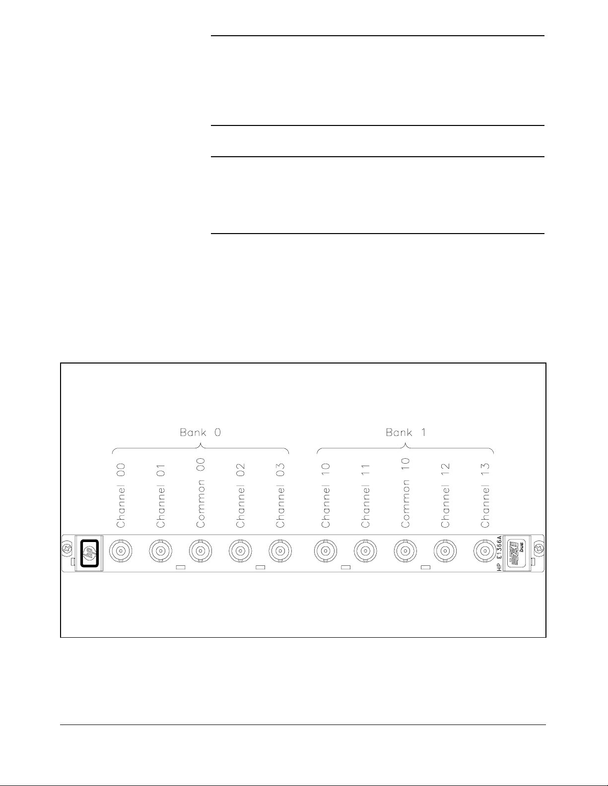
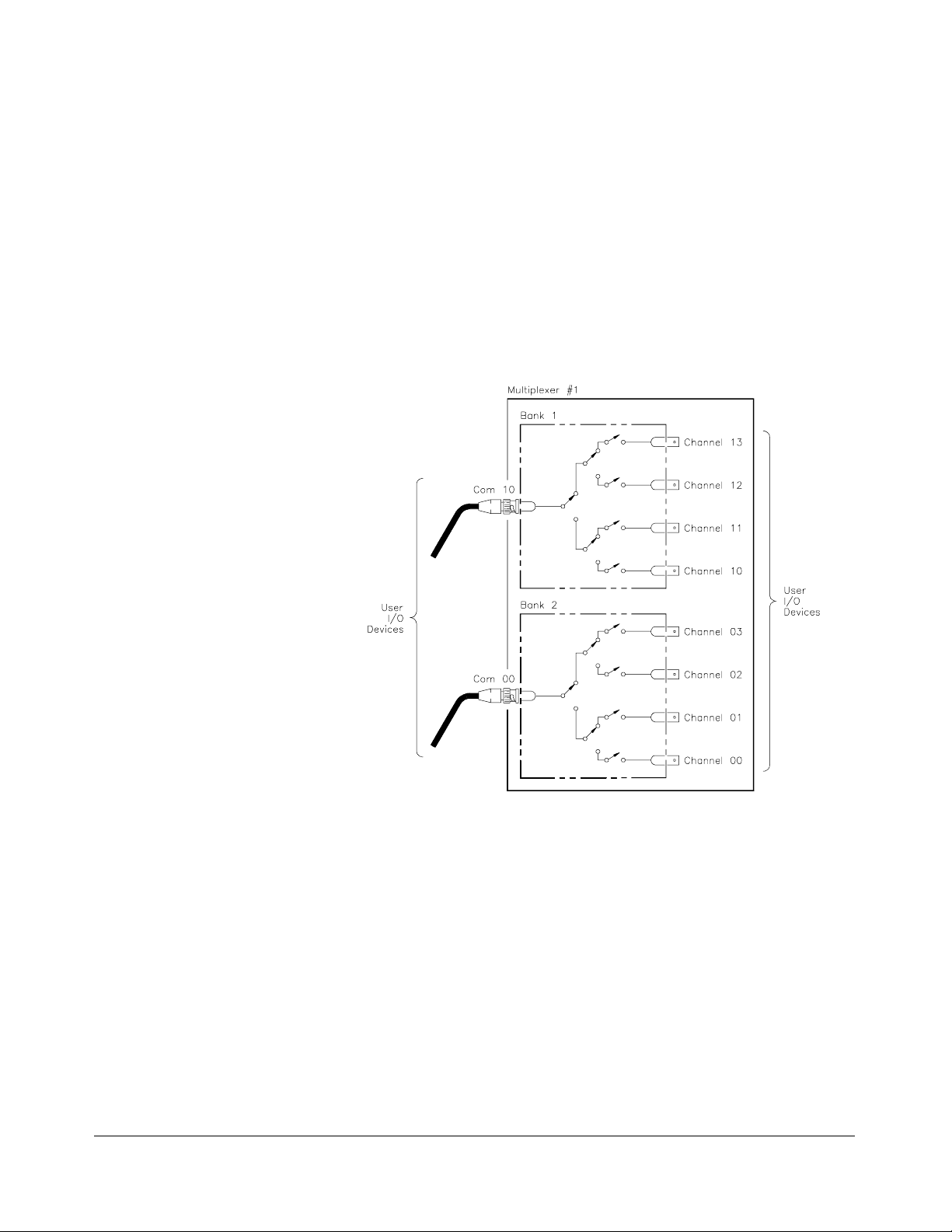
Basic Operation The multiplexers consist of two banks of channels (bank 0 and bank 1) to
form two 4:1 multiplexers. Bank 0 includes channels 00 through 03 and
com 00. Bank 1 includes channels 10 through 13 and com 10. S`ee Figure
1-1 for a simpli fied switching diagra m.
Each chann el is switched (c onnec t ed to its common) by closing the
appropriate (nonlatch ing) relays. Channels 00 through 03 can be switched
to com 00, and channels 10 through 13 can be switched to com 10. Only
one channel in ea ch ba nk can be connected to its common at a time.
User inputs a nd outp uts to eac h channel are made through BNC connectors.
When open (disconnected from common), each channel is terminated in its
characteristic impedance (50Ω for the E1366A, 75Ω for the E1367 A).
A terminati on resistor (5 0Ω for the HP E1366A or 75Ω for the HP E1367A)
is mounted on each channel, but can be remo ved as desired. At power- on or
reset, all channels are open and terminated in their characteristic impedance,
and both commons are open.
Chapter 1 Getting Started with the HP E1366A/E1367A RF Multiplexers 11
Page 12

Figure 1-1. Multiplexers Switching Diagr am
12 Getting Started with the HP E1366A/E1367A RF Multiplexers Chapter 1
Page 13

Typi cal
Configuration
The multiplexer relays are configured in a “ tree” structure which provides
high isolation and low VSWR (voltage standing wave ratio). Each channel
can switch user inputs up to 42 Vdc or 42 Vac peak. User input frequenc ies
to the multiplexers can be from dc to 1.3 GHz.
The multiplexers can be configured for several arrangements, such as
standard, tree, or matrix. You can use single scanning, multiple scanning,
or continuous scanning for any configuration.
For a SCPI (Standard C o mmands for Programm ab le Instruments)
environment, one or more multiplexers can be defined as a switchbox
instru ment. For a switchbo x instr ument, all multiplexer channels within the
instru ment can b e ad dressed using a single interfa ce a ddre ss.
Programming the Multiplexer Module
To program th e RF multip lexers using SCPI, you must select the contr olle r
language, interface address, and SCPI commands to be used. Guidelines to
select SCPI commands for the RF multiplexers follow. See the appropriate
HP B-size or C-size configuration guide for interface addressing and
controller language informatio n.
Note This discussion applies to SCPI programming. See Appendix B,
Specifying SCPI
Commands
Multip lexe r C han nel
Address
RF Multiplexers Registers, for information on multiplexer registers.
To address specific channels within an RF multiplexer, you must specify the
SCPI command and multiplexer channel address. For the RF multiplexers,
CLOSe <channel_list> to switch (close) channels and use
use
OPEN<chann el_list> to disconnec t channe ls . Use SCAN <channel_ list > to
scan (sequentially close) multiplexer channels.
For the RF multiple xers, the channel addre ss ( chann el_lis t) is in the form:
• (@ccnn) for a single channel
• (@ccnn,ccnn) for multiple channels
• (@ccnn:ccnn) for sequential channels
• (@ccnn:ccnn,ccnn:ccnn) for groups of sequential channels
• or any combination of the above
where "cc" is the multiplexer card number (01-99) and "nn" is the channel
numbers (00-03 and 10-13).
Chapter 1 Getting Started with the HP E1366A/E1367A RF Multiplexers 13
Page 14
Multiplexer Card
Numbers
The multiplexer card number depends on the switchbox configuration
(single-module or multiple-module) set for the multiplexers. (Leading
zeroes can be ignored for the card number.) For a single-module switchbox,
the card nu mber is always 01.
For a multiple-module switchbox, the card numbers are 01, 02,...,n. The
switch modu le with the lowest l ogica l a ddr e ss is a lwa ys card n u mber 01.
The card number with the next successive logical address is card number
02, and so on. See the HP B-size configuration guide for a definition of
logical addresses.
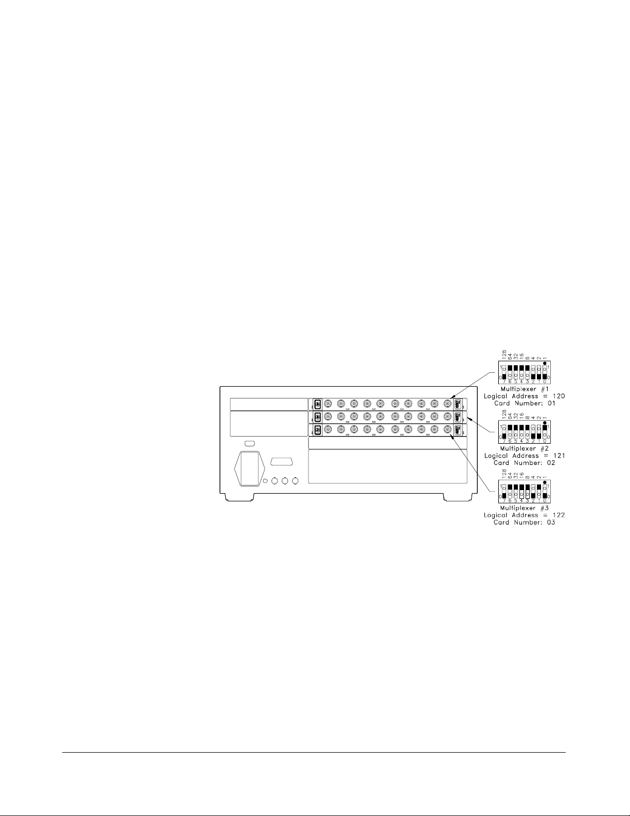
Example: Multi ple-Module Switchbox Card Numbers
Assume the three multiplexers in the following figure form a
multiple -mu ltip lex er s witc hbox ins trument with mult iple x er logica l
addresses of 120, 121, and 122. Since card nu mber 01 is assign ed to the
module with the lowest log ical addr ess , etc., t h e card numbers are as sho wn.
Figure 1-2. Multiple-Multi plexer Switch box Instru men t
Multiplexer Channe l
Numbers
RF multiplexer channel numbers are 00 through 03 and 10 through 13.
The channels can be addressed using channel numbers or channel ranges.
For a single-module switchbox, channel ranges can span across the two
channel banks. For multiple-module switchboxes, channel ranges can
span across the channels of all modules.
14 Getting Started with the HP E1366A/E1367A RF Multiplexers Chapter 1
Page 15

Use commas (,) to form a c hannel list or u se a colon (:) to form a channel
range. Only valid channels can be accessed in a channel list or channel
range. Also, the channel list or channel range must be from a lower channel
number to a higher channel numb er. For example,
acc epta ble, but
SCAN (@213:100) generates an error.
SCAN (@100:213) is
Example: RF Multiplexer Channel Lists/Ranges
Channel Lists:
Initia l Oper atio n
CLOS (@100,112)
OPEN (@203,210)
Channel Ranges:
OPEN (@100:113)
SCAN (@100:213)
!Close channels 00 and 12 on card 01
!Ope n ch anne ls 03 a nd 10 on card 02
!Open all channels on card 01
!Scan all channels on cards 01 and 02
An example program follows which uses Hewlett-Packard BASIC and SCPI
language to get you started using the RF multiplexers. The computer used in
the example is an HP 9000 Series 200/300 (or equivalent) controller with HP
BASIC as the program language. The computer interfaces to the mainframe
using the Hewlett-Packard Interface Bus (HP-IB)
*
.
This program closes channel 02 of an RF multiplexer at logical address 120
(secondary address = 120/8 = 15) and queries the channel closure state. The
result is returned to the controller and display ed (1 = chann el closed, 0 =
channel open). See the HP B-size configuration guide for information on
addressing.
Example: Close Multiplexer Channel
OUTPUT 70915;"CLOS (@102)"
OUTPUT 70915;"CLOS? (@102)" ! Query channel 02 state
ENTER 70915;Value
PRINT Valu e
END
* HP-IB is Hewlett-Packard ’s implem entat ion of IEEE Std 488. 1-1 984
! Close channel 02
Enter result into Value
!
Display result
!
Chapter 1 Getting Started with the HP E1366A/E1367A RF Multiplexers 15
Page 16

Notes
16 Getting Started with the HP E1366A/E1367A RF Multiplexers Chapter 1
Page 17

Configuring the HP E1366A/E1367A
Using This Chapter
This chapter shows how to make user connections to the RF multiplexers
and how to configure the multiplexer modules. Chapter contents are:
• Warnin gs and Cau tions . . . . . . . . . . . . . . . . . . . . . . . . . . . . . Page 17
• Connecting User Inputs . . . . . . . . . . . . . . . . . . . . . . . . . . . . . Page 18
• Typical Multiplexer Configurations . . . . . . . . . . . . . . . . . . . Page 20
• Changing Multiplexer Components. . . . . . . . . . . . . . . . . . . . Page 23
Warnings and Cautions
Warning SHOCK HAZARD. Only qualified, service-trained personnel
who are aware of the hazards involved should install, configure,
or remove the RF multiplexers. Remove all power sources from
the mainframe and installed modules before installing or
removing a module.
Chapter 2
RF Multiplexers
Warning CHANNEL WIRING INSUL ATION. All channels that have a
common connection must be insulated so that the user is
protected from electrical shock in the event that two or more
channels are connected together. This means wiring for all
channels must be insulated as though each channel carries the
voltage of the highest voltage channel.
Caution MAXIMUM VOLTAGE/CURRENT. Maximum voltage between
any RF multiplexer center conductor or shield to any other
center conductor, shield, or chassis ground is 42 Vdc or 42 Vac
peak. Maximum current per channel or common is 1 A dc or
1 A ac RMS. Maximum switching power is 24 W or 24 VA per
channel or common. Maximum power per resistive termination
is 1 W or 1 VA. Exceedin g any limit may damage the module.
Chapter 2 Configuring the HP E1366A/E1367A RF Multiplexers 17
Page 18
Caution CENTER CONDUCTOR MAY SHORT TO SHIELD. Each
channel’s center conductor may momentarily short to the
shield when the channel is opened or closed. Use only
resistive (5 0Ω or 75Ω) or current-limited (<1 A) inputs with less
th an 0.1 µF total capa cita nce .
Caution STATIC-SENSITIVE DEVICE. Use anti-static procedures when
removing, configuring, and installi n g a module . The
multiplexer modules are susceptible to static discharges. Do
not install a multiplexer without its metal shield attached.
Connecting User Inputs
User inputs to the RF multiplexers are made through user-supplied male BNC
connectors to the female BNC connectors on the modules. Figure 2-1 shows
the multiplexer femal e BNC connectors and associated chan nel numbers.
Figure 2-1. BNC Connector Locati on s
18 Configuring the HP E1366A/E1367A RF Multiplexers Chapter 2
Page 19

Some guidelines for user input cabling are:
• For best high-frequency performance, user cabling should have at
least two braided sh ields or one br a id and a f oi l wrap.
• Always use shielded coaxial cables with the characteristic
impedance of the multiplexer used ( 5 0Ω or 75Ω). Keep cables as
short as possible, especially in high-frequency circuits or pulse
circuits where a rise/fall time of <50 nsec is critical.
• Long cables can add delay time which can cause timing problems.
All test equipment, such as counters, spectrum analyzers, and
oscilloscopes, m ust be terminated i n the chara cteristic impedance to
minimize reflection loss.
• To maintain low dc offset voltages, cables should have copper center
conductors, not copper-clad steel. RG-233/U cable is recommended.
Table 2-1 lists H ewl ett-Pa c kard BNCca b les whi ch meet these
guidelines.
Table 2-1. Hewlett-Packard BNC Cabl es
Type Length Part Number
50 Ω coaxial 30 cm (12 in)
61 cm (24 in )
122 cm (48 in)
75 Ω coax i al 30 cm (12 in)
61 cm (24 in )
8120-1838
8120-1839
8120-1840
5062-6452
5063-0061
Chapter 2 Configuring the HP E1366A/E1367A RF Multiplexers 19
Page 20
Typical Multiplexer Configurations
Typical RF mult iplexer configurations are:
• Standard configuration (2 x 4:1 multiplex er)
• Tree configuration (1 x 12:1 multiplexer)
• Matrix-type configuration (4:1 to 4:1 multiplexer)
Standard
Configuration
Figure 2-2 shows the standard configuration (2 x 4:1) for the RF
multiplex ers. With this configuration, you can switch c hannels 00-03 to
com 00 and switch channels 10-13 to com 10. One channel per bank can be
connected to its common at a ti me.
Figure 2-2. Typi cal Stan d ard Co nfig uratio n
20 Configuring the HP E1366A/E1367A RF Multiplexers Chapter 2
Page 21

Tree Configuration Figure 2-3 shows a typical tree configuration which uses two RF
multiplexers to provide a 1 x 12:1 multiplexer. This configuration provides
isolation of test points while maintainin g charact eristic imp edance. With
tree configuration, signal delay time is more than doubled s ince the signal
must pass through two channel banks plus extra cabling. Keep cables as
short as possible, especially between channel banks, to minimize delay.
Figure 2-3. Typical Tree Conf iguratio n
Chapter 2 Configuring the HP E1366A/E1367A RF Multiplexers 21
Page 22

Matrix-Type
Configuration
Figure 2-4 shows the two banks of an RF multiplexer connected to form a
matrix-type arrangement. This con fi gurat ion pr o vides a way to co nnect
multiple devices under test (DUTs) to multiple test instruments. With this
configurati on, only one channel in bank 0 (one “row”) can be connected to
one channel in bank 1 ( one “colu mn”) at a time.
Figure 2-4. T ypi cal Mat rix-Type Con fi gurati o n
22 Configuring the HP E1366A/E1367A RF Multiplexers Chapter 2
Page 23
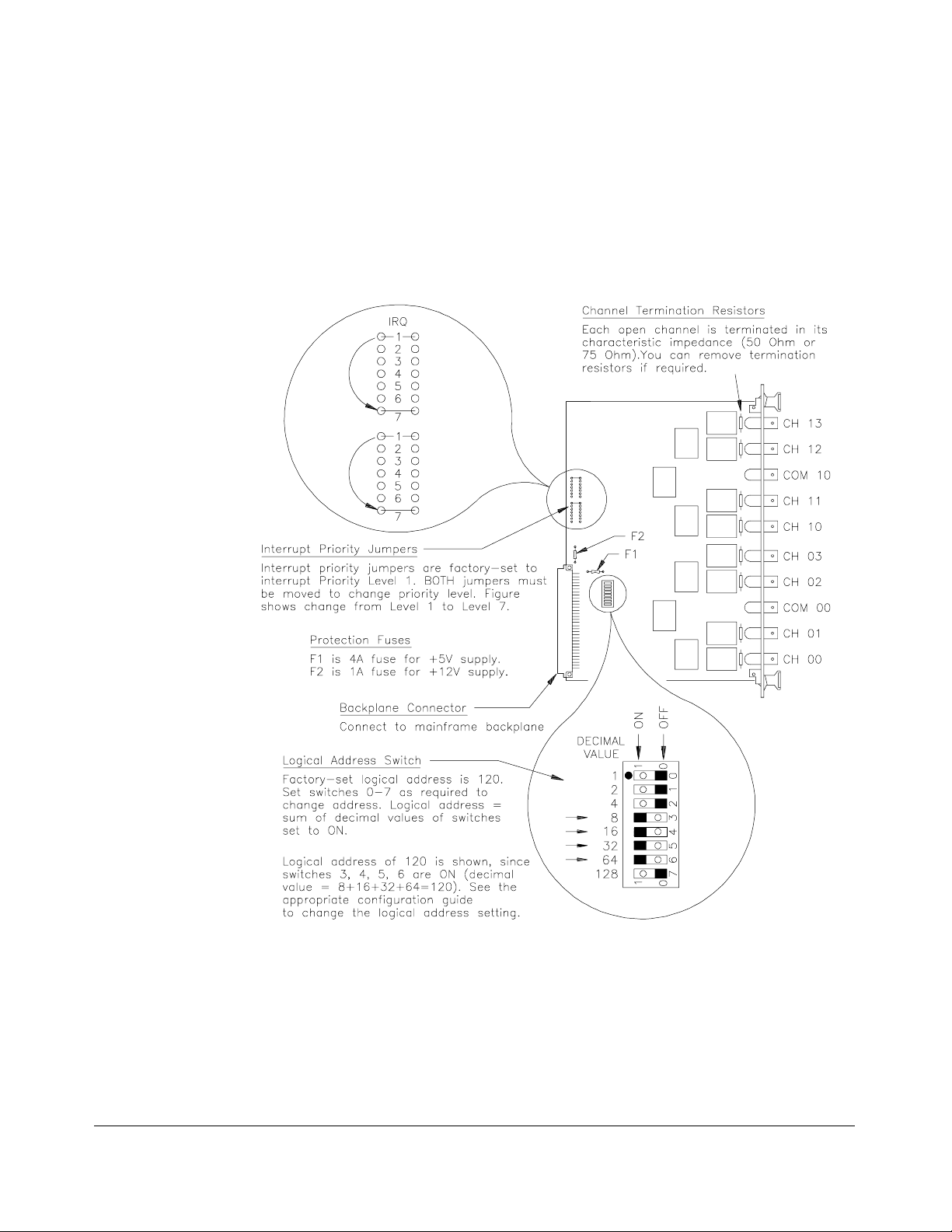
Changing Multiplexer Components
As required, you can change the logical address switch setting, replace the
protection fuses, change the interrupt priority jumper setting, or remove
channel t erminat ion r e sistors. See Figure 2 -5 f or loca tions.
Figure 2-5. RF Multiplexer Component Locations
Chapter 2 Configuring the HP E1366A/E1367A RF Multiplexers 23
Page 24

Notes
24 Configuring the HP E1366A/E1367A RF Multiplexers Chapter 2
Page 25

Using the HP E1366A/E1367A
Using This Chapter
This chapter provides examples to switch multiplexer channels and to scan
multiplexer channels. As require d see Chap t er 4, Und erstan ding the RF
Multiplexers, to modify the examples for your application. Also, see
Chapter 5, RF Multiplexers Command Reference, for command
information. C hapt er contents are:
• Mul tip lexer Commands . . . . . . . . . . . . . . . . . . . . . . . . . . . . . Page 25
• Switching Channels . . . . . . . . . . . . . . . . . . . . . . . . . . . . . . . . Page 25
• Scanning Channels. . . . . . . . . . . . . . . . . . . . . . . . . . . . . . . . . Page 29
Multiplexer Commands
Chapter 3
RF Multiplexer Module
Table 3-1. RF Multiplexer Commands Used in Chapter 3
Command Description
CLOS <channel_list>
OPEN <channel_list>
TRIG:SOUR BUS |EXT |HOLD |IMM
SCAN
INIT
Switching Channels
Close chann els
Open channels
Set scanning trigger source
<channel_list>
• Switching channels consists of closing or opening a channel. Close
channels 00-03 by connecting a channel to com 00 or close channels
10-13 by connecting a c hannel to c om 10. Only one channel per
bank can b e closed at a time.
• Use CLOSe <channel_list> to close channels use
OPEN <channel_list> to open channels. channel_list has the form
(@ccnn) for a single channel, (@ccnn,ccnn,...) for two or more
channels, or (@ccnn:ccnn) for a set of channels where cc = card
number, nn = channel number.
Define channels to be scann ed
Start scan, close fir st channel
• Switching configurations include standar d, matrix , and tree. See
Chapter 2 for configuration details.
Chapter 3 Using the HP E1366A/E1367A RF Multiplexer Module 25
Page 26

Example: Standard
Switching
This example co nnects channel 02 to com 00 of an RF multiplexer in
standard conf igurat ion. The multip lexer is defined as a single-multiplex er
switchb ox instrument. See the following figure for typ ical user
connections. To connect channel 02 to com 00, execute:
CLOS (@102) ! Connect ch anne l 02 to com 00.
To open th e channel, u s e OPEN (@102).
1 is the card numbe r and 02 is the
channel numbe r.
Figure 3-1. Standard Switching
26 Using the HP E1366A/E1367A RF Multiplexer Module Chapter 3
Page 27

Example: Tree
Switching
This example uses two RF multiplexers in a tree configuration to connect
com 10 of multiplexer #1 with channel 12 of multiplexer #2. The two
multiple x ers form a multip le-m u ltip lex er switc hb ox instr ument with
multiplexer #1 as card 01 and multiplexer #2 as card 02. See the following
figure for typical user connections. To make this connection, execute:
CLOS (@112,212) ! Con nect com 10 of multipl exer #1
To open th e channels, use OPEN (@112,212).
to channel 12 of multiplexer #2.
Figure 3-2. Tree Swi tchin g
Chapter 3 Using the HP E1366A/E1367A RF Multiplexer Module 27
Page 28

Example:
Matrix-Type
Switching
This examp le co nnects c hanne l 13 to channel 01 of an RF multiplexer in
matrix-type configuration. The multiplexer is defined as a single-module
switchb ox instrument. See the following figure for typ ical user
connectio ns.
To connect channel 13 to channel 01, execute:
CLOS (@101,113) ! Connect channel 01 to c hannel 13.
1 is the card number and 01 , 13
are channel numbers.
Figure 3-3. Matrix-Typ e Switch i ng
To open the channels, u s e OPEN (@101,113).
Switching
Channels
Comments
Query Channel States. Use CLOSe? <channel_ list > or
OPEN? <channel_list> to query the channel states (open/cl os ed). CLOSe?
returns a 1 for channels closed, 0 for channels open. OPEN? returns a 0 for
channels closed, 1 for channels open. (Commands do not account for relay
hardware failures.)
Channel Closure Order.
multiple c hannels (o ne at a time). Ho wever, the sequ ence in which multiple
channels are closed wit h a single command is n ot guarant eed.
CLOSe <channel_ list > can b e us ed to close
28 Using the HP E1366A/E1367A RF Multiplexer Module Chapter 3
Page 29

Scanning Channels
• Scanning channels consists of closing a set of channels, on e channel
at a time. You can scan any combination of channels for a
single-multiplexer or multiple-multiplexer switchbox.
• Single, multiple, or continuous scanning modes are available. Any
switching c onfigurat ion can be used for scanning. See Chapt er 4.
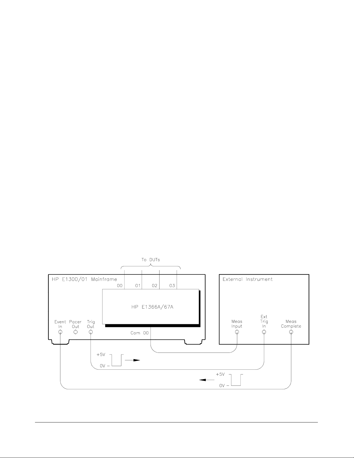
Example: Scanning
Using Trig Out Port
This example shows one way to synch ronize instrument meas urements of DUTs
with RF multiplexer channel closures. For measurement synchronization, the HP
E1300A/E1301A Trig Out B NC port is conne cted to the instrument External
Trigger In port. See the following figure for typical user connections.
For this exa mple, the main fra me a nd instru ment are c onnected via HP-IB
with mainfra me address of 709 an d instrume nt a ddr e ss of 722. The RF
multiplexer is at logical address 120 ( s econdary addre ss 15). (You must add
required inst rume nt c ommands to line 10.)
10 OUTPUT 722;"TRIG EXT;...." ! Ext triggering
20 OUTPUT 70915;"OUTP ON" ! Enable Trig Out
30 OUTPUT 70915;"TRIG:SOUR BUS" ! Bus triggering
40 OUTPUT 70915;"SCAN (@100:103)" ! Scan channe ls
50 OUTPUT 70915;"INIT" ! Enable scan
60 FOR I=1 TO 4 ! Start loop
70 ENTER 722;A ! Enter re sult
80 PRINT A ! Display result
90 TRIGGER 70915 ! Advance scan
100 NEXT I ! Incre me nt coun t
110 END
Figure 3-4. Scann i ng Usin g Trig Out Po rt
Chapter 3 Using the HP E1366A/E1367A RF Multiplexer Module 29
Page 30

Scanning Channels
Comments
Scan List Can Extend Across Boundaries. For multiple-multiplexer
switchbox instruments, the scan list can extend across multiplexer
boundaries. For example, for a two-multiplexer switchbox instrument,
SCAN (@100:213) will scan all channels in both multiplexers.
Setting Multiple/Continuous Scans. Use
from 1 to 32767 scans through the scan list. Use
continuous scanning. See Chapter 4.
ARM:COUN <number> to set
INIT:CO NT O N to set
30 Using the HP E1366A/E1367A RF Multiplexer Module Chapter 3
Page 31

Understanding the HP E1366A/E1367A
Using This Chapter
This chapter explains techniques to scan RF multiplexer channels and
shows how to use th e Sca n Complete bit. The c ha pter contents are:
• Scanning Channels Commands . . . . . . . . . . . . . . . . . . . . . . Page 31
• Using Scanning Trigger Sources . . . . . . . . . . . . . . . . . . . . . Page 31
• Scanning with External Instruments. . . . . . . . . . . . . . . . . . . Page 31
• Using the Scan Complete Bit . . . . . . . . . . . . . . . . . . . . . . . . Page 36
Scanning Channels Commands
Scanning RF multiplexer channels consists of closing a set of channels, one
at a time. Single scan, multiple (2 to 32767) scans, or continuous scanning
modes are available. See Figure 4-1 for scanning commands.
Chapter 4
RF Multiplexers
Using Scanning Trigger Sources
The TRIG:SOUR command specifies the source to advance the scan. You
can use the
TRIG:SOUR HO L D is set. The OUTP command can be used to enable the
HP E1300A/E1301A Trig Out or the HP E1405A/E1406A port. Figure 4-2
shows scanning trigger sources.
TRIG command to advance the scan when TRIG:SOUR BUS or
Scanning with External Instruments
Scanning RF multiplexer channels has the same effect as executing multiple
CLOSe command s. Thus, scanning is useful when the outputs 7from a
number of DUTs are to be measured with an instrument. Two examples
using HP BASIC programmin g language f ollow.
Chapter 4 Understanding the HP E1366A/E1367A RF Multiplexers 31
Page 32

Sets Number of Scanning Cycle s
ARM:COUN<number> sets 1 to 32767 scans
through the channel list per INIT command.
Default is one scanning cycle.
Selects the Trigger Source
TRIG:SOUR defines the trigger source to
advance th e scan. Default is TRIG:SOUR IMM.
TRIG:SOUR?
queries the current trigger source.
Sources are:
BUS = *TRG via HP-IB interface
EXT = Ev ent In connector
HOLD = Hold trigge ring
IMM = Automatic advance
Selects Continuous Scanning Cycles
Use INIT:CONT ON or INIT:CONT 1 to enable
continuous scanning cycles. Default made is
fixed number of scans, with number set by
ARM:COUN<number>.
Selects Scan Mode
SCAN:MODE sets the RF multiplexers for
NONE, VOLT, RES, or FRES. NONE, VOLT,
and RES have no effect on RF multiplexer
operation.
FRES sets "paired-channel"
scanning.
Selects the Scan List
SCAN<channel_list> defines channels to
be scanned using the trigger source set by
TRIG:SOUR command.
the
Enables Scanni ng
INIT starts scanning for any trigger source
and closes the first channel in the channel list
Advances the Scan
TRIG can be used to advance th e sca n for
TRIG:SOUR BUS or TRIG:SOUR HOLD. The
command is not functional when TRIG:SOU R IM M
or TRIG:SOUR EXT is set.
Figure 4-1. Scanning Channels Commands
.
32 Understanding the HP E1366A/E1367A RF Multiplexers Chapter 4
Page 33

Immediate Tr igg ering (TRI G: SO UR IMM)
TRIG:SOUR IMM sets immediate
(internal) triggeri ng. The scan list is
automatical ly advanc ed. This is th e
default trigger mode .
External Trigger (TRIG)
TRIG:SOUR EXT s ets external
triggering . The trigger sour ce is a
(user supplied) input to the Event In
port. Use a +5V negative-g oing pul s e
to trigger.
Trigger Hold (TRIG:SO UR HO LD)
TRIG: S O UR HOLD pre v en ts execu tio n
of triggers until trigger source is changed.
Can use TRIG command to trigger a
switchbo x set to TRIG:SO UR HOL D.
Advance Scan (TRIG)
Can use TRIG command to ad-
vance the scan list when switchbox is in TRIG:SOUR HOLD or
TRIG:SOUR BUS. Fo r eith er
trigger sourc e, the scan l ist
advances one channel per
TRIG command .
Bus Triggering (TRIG :SO UR BUS)
TRIG:SOUR BUS defines trigger
source as a *TRG or GET
command ex ecuted ov er the HP-I B.
With TRIG:SOUR BUS, t he scan list
is advanced for each *TRG or GET
command received.
With two or more switchb o xes in a
mainframe, t he first switchbo x set for
EXT trigger keeps the trigger resource
until the switchbox source is changed
to BUS, HOLD, or IMM.
Enabling Trig Out Port (OUTP ON)
The Trig Out port is shared by all
instr uments i n the mainfram e. With
the port enabled (with OUTP ON), it
generates an output trigger after
each channel closure for ANY
switchbox in the mainframe. T h e
Trig Out port outputs a +5V
negative-going pulse.
Figure 4-2. Scanning Trigger Sources
Chapter 4 Understanding the HP E1366A/E1367A RF Multiplexers 33
Page 34

Example: Scanning
with External Device
This example uses the HP E1300A/E1301A mainframe "Trig Out" port to
synchronize the RF multiplexer channel closures to an external
measurement device. See the figure below for typical user connections.
For measur em ent synchro ni za t ion, t he HP E1300A/E1301A Trig Out BNC
port is connected to the instrument External Trigger In port.
For this example, the HP E1300A/E1301A and the instrument are
connected via HP-IB with HP E1300A/E1301A address of 709 and
instrument address of 722. The RF multiplexer logical address is 120
(secondary address =120/8 =15). The measurements are transferred
directly to the computer. (Appropriate instrument commands must be
added to line 10.) The sequence of operation is:
1. INIT (line 50) closes channel 100.
2. The channel closure causes a trigger output from the "Trig Out" port.
3. Trigger t o Ext Trig In initiates c hanne l 100 measurement.
4. Result is sent to the co mput er (lin es 60 to 80).
5. TRIGGER command (line 90) advances the scan to channel 101.
6. Steps 2-5 are repeated for chann els 101 through 102.
10 OUTPUT 722;"TRIG EXT;..." ! Configure inst rument
20 OUTPUT 70915;"OUTP ON" ! Enables "Trig Out" port
30 OUTPUT 70915;"TRIG:SOUR BUS" ! HP-IB bus trigge ring
40 OUTPUT 70915;"SCAN (@100;102)" ! Scan c han nels 00- 02
50 OUTPUT 70915;"INIT" ! Enable scan
60 FOR I = 1 TO 3 ! Start count lo op
70 ENTER 722;A ! Enter readi ng
80 PRINT A ! Display reading
90 TRIGGER 70915 ! Advance scan
100 NEXT I ! Increment coun t
110 END
Figure 4-3. Scanning with External Device
34 Understanding the HP E1366A/E1367A RF Multiplexers Chapter 4
Page 35
Example: Scanning
Using "Trig Out"
and " Event In"
Ports
This example uses the HP E1300A/E1301A mainframe "Trig Out" and
"Event In " ports to sync hron iz e RF multiple x er channel c losur es wit h an
external measurement device. See the figure below for typical user
connections. For this example, the mainframe and instrument are connected
via HP-IB with mainframe address of 709 and instrument address of 722.
The RF multiplexer’s logi cal addre ss is 120 ( seco ndary ad dress =1 20/8 =15).
With this example, since synchronization with the computer cannot be
ensured, the external instrument must have internal memory capacity to
store the readings. Also, you must add the appropriate instru ment
commands to l ine 10. The sequ ence of operation is:
1. INIT (line 50) closes channel 100.
2. The channel closure causes a trigger output from the "Trig Out" port.
3. Trigger to Ext Trig In star ts channel 100 me a surement.
4. Channel 100 measurement r esult is stor ed i n instru me nt.
5. Trigger is t hen ou tput from multimeter’s "MEASUREMENT
COMPLET E " p or t.
6. Trigger to "Event In" port advances scan to channel 101 .
7. Steps 2-6 are repeated for chann els 101 through 102.
10 OUTPUT 722;"TRIG EXT;..." ! Configure instrument
20 OUTPUT 70915;"OUTP ON" ! Enables "Trig Out" port
30 OUTPUT 70915;"TRIG:SOUR EXT" ! Event In trigge ri ng
40 OUTPUT 70915;"SCAN (@100:102)" ! Scan c han nels 00- 02
50 OUTPUT 70915;"INIT" ! Enable scan
60 END
Figure 4-4. Scan Usin g "Tri g Out" and "Even t In" Ports
Chapter 4 Understanding the HP E1366A/E1367A RF Multiplexers 35
Page 36

Using the Scan Complete Bit
You can u se the Scan Complet e Bit (bit 8) in the Operation Status re g ister
of a switchbox to determine when a scanning cycle completes (no other bits
in the register apply to the switchbox). Bit 8 has a decimal value of 256 and
you can read it directly with the
STATu s:OPERati o n[ :E VENt ]? command in Chapter 5 for an example.
STAT:OPER ? command. R efer to
Example : Scan
Complete Interrupt
When enabled by the
STAT:OPER:E NAB 2 5 6 comma nd, the Scan Comp lete
Bit will be reported as bit 7 of the Status register. Use the HP-IB Serial Poll
or the IEEE 488.2 C ommon Command
When b it 7 of the Status r egister is e n a bled by the
*STB? to read the Status register.
*SRE 128 Common
Comman d to assert an HP-IB Service Request (SRQ), you can int errupt the
comput er when the Scan Complet e Bit is set, after a scanning cycle
complet es. This al lows the controller to do other operations while the
scannin g cycle is in progress.
The following example monitors bit 7 in the Status register to determine
when the scanning cycle completes. The computer used in this example is
an HP 9000 Series 200/ 300 us ed wit h HP B ASIC as the progr amm ing
language. The computer interfaces wit h an HP E1300A/E1301 A mainfra me
over HP-IB. The HP-IB select code is 7, the HP-IB primary address is 09,
and the HP-IB secondary address is 15.
10 OUTPUT 70915;"*CLS" ! Clear all switchbox status structure
20 OUTPUT 70915;"STAT:OPER:ENAB 256"
30 OUTPUT 70915;"*SRE 128" ! Enable bit 7 of Status register to
40 OUTPUT 70915;"TRIG:SOUR EXT" ! External trigger mode
50 OUTPUT 70915;"SCAN (@100:105)" ! Select channe ls to be scann ed
60 OUTPUT 70915;"INIT" ! St art sc ann ing cycle
70 WHILE NOT BIT(SPOLL(70915),7)
80 PRINT "DO OTHER OPERATION HERE"
90 END WHILE
100 PRINT "INTERRUPT GENERATED" ! Program goe s to this l ine after
110 END
! Enable Scan Complete Bit to
set bit 7 in Status r egister
assert SRQ
! Wait ing for scan compl et e
! Enter program lines for
computer to do other oper ations
interrupt generated by a completed
scanning cycle
36 Understanding the HP E1366A/E1367A RF Multiplexers Chapter 4
Page 37

HP E1366A/E1367A RF Multiplexers
Using This Chapter
This chapter describes Standard Commands for Programmable Instruments
(SCPI) and su mmar izes IEEE 488.2 C omm on (*) commands applicable to
both RF Mu lt iplexer modules. See the appropriate HP B-siz e or C-s ize
configurat ion guide for additional information on SCPI and Common
commands. This chapter contains the following sections.
Command Types
Chapter 5
Command Reference
• Command Types . . . . . . . . . . . . . . . . . . . . . . . . . . . . . . . . . . Page 37
• SCPI Command Reference . . . . . . . . . . . . . . . . . . . . . . . . . . Page 40
• IEEE 488.2 Common Commands . . . . . . . . . . . . . . . . . . . . . Page 59
• Command Quick Reference. . . . . . . . . . . . . . . . . . . . . . . . . . Page 60
Common
Command Format
SCPI Command
Format
Comman ds are s eparat ed i nto two types: IEEE 488.2 Comm on commands
and SCPI commands.
The IEEE 488.2 standard de fines the Common comma nds that perform
functions like reset, sel f-test, stat us byte query , etc. Common commands
are four or five characters in length, always begin with the asterisk character
(*), and may include one or more parameters. The command keyword is
separated from the first parameter by a space character. Some examples of
Common c ommands a r e s hown below:
*RST *ESR 32 *STB?
SCPI commands perform functions like closing switches, and querying
instru ment states or retrieving data. A subsystem c omma nd structure is a
hierarchical st ru ct ur e that usua lly consists of a t op-level (or root) c omma nd,
one or more lower-level commands, and their parameters. The following
example shows part of a typical subsystem:
[ROUTe:]
CLOSe<
SCAN<
channel_list>
channel_list>
:MODE?
[ROUTe:]
commands with parameters, and
Chapter 5 HP E1366A/E1367A RF Multiplexers Command Reference 37
is the root command, CLOSe and SCAN are second-level
:MODE? is a third-level command.
Page 38

Command Separator A colon (:) always separates one command from the next lower-level
command as shown below:
ROUTe:SCAN:MODE?
Colons separate the root command from the second-level command
[ROUTe:]SCAN) and the second level from the third level (SCAN:MODE?).
(
Abbreviated
Commands
The command syntax shows most commands as a mixture of upper- and
lowercase le tters. The uppercase let ters indicate the abbrevia ted spelling f or
the command. For shorter program lines, send the abbreviated f orm. For
better program reada b ility, you may s end the entire command. The
instrument will accept either the abbreviated form or the entire command.
For example, if t he comma nd synta x s hows
MEASURE are both acceptable forms. Other forms of MEASure, such as
MEASU or MEASU R w ill ge ne r a te an error. You ma y use upper- or
lowercas e letter s. The refore,
MEASURE, m e a s ur e, a nd MeAsUrE are all
MEASure, then MEAS and
acceptable.
Implied Commands Implied co mmands are thos e which appear in square brack ets ( [ ] ) in the
command syntax. (Note that the brackets are not part of the command and
are not sent to the instrument.) Suppose you send a second-lev el command
but do not send the preceding implied command. In this case, the
instru ment assu mes you intend to us e the implied c ommand and it res ponds
as if you had sent it. Examine the
[SOURce:]
PULSe
:COUNt <
:COUNt? [<MIN | MAX>]
:PERiod <
:PERiod? [<MIN | MAX>]
count>
period>
SOURce subsystem shown below:
The root command SOURce: is an implied command. To set the
instru ment’s puls e count to 25, you can s end either of the fol lowin g
command statements:
SOUR:PULS:COUN 2 5 or PULS:COUN 25
38 HP E1366A/E1367A RF Multiplexers Command Reference Chapter 5
Page 39

Parameters Parameter Types. Th e following table contains explanations and examples
of parameter t ypes you mi ght s ee lat er in this chapt er.
Table 5-1. SCPI Parameter T yp e s
Parameter Type Explanations and Examples
Numeric Accepts all commonly used decimal representations of
Boolean Repres ents a single binar y conditi on that is eith er
Discrete Selects from a finite number of values. These parameters
numb ers i ncluding o pt ional signs, decimal points, and
scientific notation.
123, 123E2, -123 , -1. 23E2, .123, 1.23E- 2, 1. 23000E-01.
Special cases include MIN, MAX, and INF.
true or f als e.
ON, OFF, 1, 0.
use mnemonics to represent each valid setting.
An example is the TRIGger:SOURce <
where <
source> can b e BUS, EXT, HOL D, or IMM.
source> command
Optional Parameters. Parameters shown within square brackets ( [ ] ) are
optional parameters. (Note that the brackets are not part of the command
and are not sent to the instr ument.) If you do not specif y a value for an
optional parameter, the instrument chooses a default value. For example,
consider the
com man d w i t hout s pec ifying a p ar ame ter, the pr esent
returned. If you send the
minimum count available. If you send the
ARM:COUNt ? [<MIN | MAX>] co mmand. If you send the
ARM:COUNt value is
MIN parameter, the command returns the
MAX parameter, the command
returns the maximum count available. Be sure to place a space between the
command and t he par ameter.
Linking Commands Linking IEEE 488.2 Common Commands with SCPI Commands. Use
a semicolon (;) between the commands. For example:
*RST;OUTP ON or TRIG:SOUR HOLD;*RST
Linkin g Mul tip le S CPI Co mma nds . U se both a s emicolon (;) and a colon
:) between the commands. For example:
(
ARM COUN 1;:TRIG:SOUR EXT
Chapter 5 HP E1366A/E1367A RF Multiplexers Command Reference 39
Page 40

SCPI Command Reference
This section describes the Standard Commands for Programmable
Instru ments (SCPI) commands for the RF multiplexers. Commands are
listed alphabetically by subsystem and within each subsystem.
ABORt
The ABORt subsystem stops a scan in pr o gress when t he scan is enabled via
the interface, and the trigger modes are
TRIGger:SOURce HOLD.
Subsystem Syntax ABORt
Comments • ABORt operation invalidat es the current channel list and s ets
ARM:COUNt 1 (o ne scanning cycle per INITiate command), sets
INITiate CONT inuous OFF (no continuous scanni ng cycles) , an d sets
TRIGger:SOURce IMMediate (continuous internal triggering).
• Stopping Scans Enabled from Interface: When a scan is enabled
from the interface, use an interface
HP E1301A front panel “Reset Instr” or “Clear Instr” key to stop
the scan.
TRIGger:SOURce BUS or
CLEAR command or the
When the scan is enabled from the interface and the trigger source is
TRIGger:SOURce BUS or TRIGger:SOURce HOL D, u se ABORt or
the HP E1301A front panel “Reset Instr” or “Clear Instr” key to
stop the scan.
• Stopping Scans Enabled from Front Panel: When a scan is
enabled from the HP E1301A front panel, execute
the interface or the front panel “Reset Instr” or “Clear Instr” key to
stop the scan.
• Related Commands: ARM, INITiate:CONTinuous, [ROUTe:]SCAN,
TRIGge r
Example Stopping a Scan with ABORt
TRIG:SOUR BUS !
INIT:CONT ON ! Set continuous sc ann ing
SCAN (@100:103) ! Scan channe ls 00-03
INIT ! Start scan, close c hannel 00
.
.
ABOR ! Abort scan in progress
*RST entered via
*TRG
command is trigger source
40 HP E1366A/E1367A RF Multiplexers Command Reference Chapter 5
Page 41

ARM
Subsystem Syntax ARM
The ARM subs ystem selects the number of scanni ng cycles (1 through
32767) for each
:COUNt <
:COUNt? [MIN | MAX]
INITiate command.
number> MIN | MAX
:COUNt ARM:COUNt <number> MIN | MAX allows scanning cycles to occur a
multiple of ti mes (1 to 32767) with on e
INITiate:CONTinuous OFF |0 is set. MIN sets 1 cycle and MAX sets 32767
cycles.
Parameters
Parameter Name Parameter T ype Range of Values
INITia te command when
<number>
numeric 1 |32767 |MIN |MAX
Comments • Number of Scans: Use only values between 1 to 32 767 for the
numb er of sca nning cycles .
• Related Commands: ABORt, INITiate:IMMediate
• *RST Condit ion: ARM:COUNt 1
Example Setting Ten Scannin g Cycles
This example sets an RF multiplexer for 10 scans of channels 00 through
03. When the scan sequence completes, channel 03 is closed.
ARM:COUN 10 ! Set 10 scans per INIT command
SCAN (@100:103) ! Scan channe ls 00-03
INIT ! Start sc an, close c hannel 00
Chapter 5 HP E1366A/E1367A RF Multiplexers Command Reference 41
Page 42

:COUNt? ARM:COUNt? [MIN | MAX] returns cur r e nt number of scanning cycles s et
ARM:COUNt. The current number of scan cycles is returned when MIN
by
or MAX is not supplied. With MIN or MAX pass ed a s pa ra meter s, MIN
returns 1 and MAX returns 3276 7.
Parameters
Parameter Name Parameter T ype Range of Values
MIN | MAX numeric MIN = 1, MAX = 32767
Comme nt s • Related Commands: INITiat e[: IM Mediate]
Example Query Number of Scanning Cycles
This example sets a switchbox for 10 scanning cycles of channels 00
through 03 and queries the number of scan cyc les set. The
command retur ns 10.
ARM:COUN 10 ! Set 10 scans per INIT command
ARM COUN? ! Que ry number of scans
ARM:COUN?
42 HP E1366A/E1367A RF Multiplexers Command Reference Chapter 5
Page 43

DISPlay
The DISPlay subsystem monitors the channel state of a selected module
(or card) in a switchbox. This subsystem operates only with mainframes
which have a display, su ch as the HP 75000 Ser ies B Mainframe
(HP E1301A).
Subsystem Syntax DISPlay
:MONitor
[:STAT e] <
:CARD <
:MONitor[:STATe ] DISPlay:MONitor[:STATe] <boolean > turns the monitor mode on or off.
Parameters
Parameter Name Parameter T ype Range of Values
ON | OFF | 1 | 0 boolean ON | OFF | 1 | 0
Comme nt s • Moni toring Swit chbo x Chan n els : DISPlay[:STATe] ON or
DISPlay[:STATe] 1 turns the monitor mode on to show the channel
state of the selected module .
DISPlay[:STATe] 0 turns the monitor mode off.
boolean>
number> | AUTO
DISPlay[:STATe] OFF or
• Selecting the Module to be Monitored: Use the
DISPlay:MONi tor :CARD <number> AUTO command to select the
module.
• Monitor Mode on an HP E1301A Mainframe Display: A typical
display for the HP E1366A or HP E1367A RF Multiplexer module
follows, where channel 00 (in bank 0) and channel 13 (in bank 1) are
closed.
B0:0 B1:3
• *RST Condit io n: DI SPl a y :MONit or [ :ST ATe] OF F | 0
Example Enabling the Monitor Mode
DISP:MON:CARD 2 ! Selects m od ule #2 in a s witchbox
DISP:MO N 1 ! Turns the monitor mode ON
Chapter 5 HP E1366A/E1367A RF Multiplexers Command Reference 43
Page 44

:MONitor:CARD DISPlay:MONitor:CARD <number> | A UTO selects the module in a
switchbox to be monitored.
Parameters
Parameter Name Parameter T ype Range of Values
number> | AUTO
<
numeric 1-99
Comments • Selecting a Specific Module to be Monitored: Use the
DISPlay:MONitor:CARD c ommand to s end the module nu mber for
the switchbox to be monitored.
• Selecting the Present Module to be Monitored: Use the
DISPlay:MONitor:AUTO command to select t he la st module
addressed by a switching command (e.g.,
[ROUTe:]CLOSe).
• *RST Co ndition: DISPlay:MONitor:CARD AUTO
Example Select Module #2 in a Switchbox for Monitoring
DISP:MON:CARD 2 ! Selects m od ule #2 in a s witchbox
44 HP E1366A/E1367A RF Multiplexers Command Reference Chapter 5
Page 45

INITiate
Subsystem Syntax INITiate
:CONTinuous INITiate:CONTinuous ON | OFF | 1 | 0 enab les or disables continuous
The INITiate subsystem selects continuous scanning cycles and starts the
scanning cycle.
:CONTinuous ON | OFF | 1 | 0
:CONTinuous ?
[:IMMediate]
scanning cycles for the switchbox.
Parameters
Parameter Name Parameter T ype Range of Values
ON | OFF | 1 | 0 boolean ON | OFF | 1 | 0
Comme nt s • Continuous Scanning Operation: Continuous scanning is enabled
with the
command. Sending the INITiate[:IMMediate] command closes the
first channel in the channel list.
INITiate:CONTinuous ON or INITiate:CONTinuous 1
• Each trigger from a trigger source selected by the TRIGger:SOURce
command advances the scan through the channel list. A trigger at
the end of the channel list closes the first channel in the channel list
and the scan cycle repeats.
• Non-Continuous Scanning Operat io n: This is enabled with the
INITiate:CONTi nuous OFF or INIT:CONT 0 command. Sending the
INIT:IMM command closes the first channel in the channel list.
Each trigger from a trigger source selected by the
command advances the scan through the channel list. At the end of
the scanning cycle, all channels in the channel list are closed.
• Stopping Continuous Scans: See the ABORt command.
• Related Commands: ABORt, ARM:COUNt, TRIGger
• *RST Co ndition: INITiate:CONTinuous OFF
Example Enabling Continuous Scans
This example enables continuous scanning of channels 00 through 03 of a
single-module switchbox. Since
set, use an interface clear command (such as
TRIGger:SOURce
TRIGger:SOURce IMMediate (default) is
CLEAR) to stop the scan.
INIT:CONT ON ! Enable continuous scanning
SCAN (@100:103) ! Define channel list
INIT ! St art sc an c y cle , clo se c han ne l 00
Chapter 5 HP E1366A/E1367A RF Multiplexers Command Reference 45
Page 46

:CONTinuous? INITiate:CONTinuous? queries the scanning state. With continuous
scannin g enabled, the c omma nd r e turns 1. With continuous scanning
disabled, the command returns 0.
Example Query Continuo us Sc an ning Sta te
This example enables continuous scanning of a switchbox and queries the
state. Since co ntinu ous scanning is enabl ed,
INIT:CONT ON ! Enable continuous scanning
INIT:CONT? ! Query continuous scanning state
INIT:CO NT? returns 1.
[:IMMediate] INITiate[:IMMediate] starts the scanning cycle and closes the first channel
in the channel list. Successive triggers from the source selected by the
TRIGger:SOURce command advances the scan through the channel list.
Comments • Starting the Scanning Cycle: The INITiate[: IMMediate] command
starts scanning by closing the first channel in the channel list. Each
trigger rec eived adva nces the scan to the next channel in the channel
list. An invalid channel list def inition ge ne r a tes an error (see
[ROUTe:]SCAN c ommand).
• Stopping Scanning Cycles: See the ABORt command.
Example Enabling a Single Scan
This example enable s a s ingle scan of channels 00 through 03 of a
single-module switchbox. Th e trigger source to advanc e the scan is
immediate (internal) triggering set with (default)
IMMediate.
SCAN (@100:103) ! Scan channe ls 00-03
INIT ! Begin scan, close channel 00 (use
TRIGger:SOURce
immediate trigg eri n g)
46 HP E1366A/E1367A RF Multiplexers Command Reference Chapter 5
Page 47

OUTPut
Subsystem Syntax OUTPut
The OUTPut subsystem enab les or disables the “Trig Out” port of the
HP E1300A/E130 1 A mainframe or the HP E1405A/E1406A module.
[:STATe] ON | OFF | 1 | 0
[:STATe]?
[:STATe] OUTP u t [:STATe] ON | O FF | 1 | 0 enables/disables the “Trig Out” port on
the rear panel of the HP E1300 A/E1301A mainframe or the
HP E1405A/E140 6 A module.
OUTP ut[ :ST AT e ] OF F | 0 disables the port.
and
Parameters
Parameter Name Parameter T ype Range of Values
ON | OFF | 1 | 0 boolean ON | OFF | 1 | 0
Comme nt s • Enabling “Trig Out” Port: When enabled, a pu ls e is ou tput from
the “Trig Out” port after each scanned switchbox channel is closed.
If disabled, a puls e is not output from the port after channel closur es.
The output pulse is a +5 V negative-going pulse.
OUTPut [: ST AT e] ON | 1 enables th e port
• “Trig Out” Port Shared by Switchboxes: When enabled, the
“Trig Out” port is pulsed by any switchbox each time a scanned
channel is closed. To disable the output for a specific switchbox,
send the
that switchbox.
OUTP ut[:STAT e] OFF or OUTPut[:STATe] 0 command for
• Related Commands: [ROUTE:]SCAN, TRIGger:SOURce
• *RST Condition: OUTPut[:STATe] OFF (port disabled)
Example Enable "Trig Out" Port
OUTP :STAT ON ! Enable “Trig Out” port to output
pulse after each scanned channel is
closed
[:STATe]? OUTPut[:STATe]? queries the present state of the “ Trig Out” port. The
command returns 1 if the port is enabled or 0 if the port is disabled.
Example Query “Trig Out” Port Enable State
This example enables the “Trig Out” Port and queries the enable state. The
OUTPut[:STATe]? command returns 1 since the port is enabled.
OUTP :STAT ON ! Enable “Trig Out” port
OUTP:STAT? ! Query port enable state
Chapter 5 HP E1366A/E1367A RF Multiplexers Command Reference 47
Page 48

[ROUTe:]
Subsystem Syntax [ROUTe:]
The ROUTe subsystem controls switching and scanning operations for RF
multiplexer modules in a switchbox.
CLOSe <
CLOSe? <
OPEN <
OPEN? <
SCAN <
channel_list>
channel_list>
channel_list>
channel_list>
channel_list>
:MODE NONE | VOLT | RES | FRES
:MODE?
CLOSe [ROUTe:]CLOSe <channel_list> closes the RF multiplexer channels
specified by channel_list. The channel_list has the form (@ccnn) where
cc = card nu mber (01-99) and nn = channel number (00-03 and 10-13).
Parameters
Parameter Name Parameter T ype Range of Values
<channe l_list>
numeric cc00-cc03 , cc10- cc13
Comme nt s • Closing Channels: To close:
– a single channel, use [ROUTe:] CLO Se (@c cnn)
–
multiple channels, use [ROUTe:]CLOSe (@ccnn,ccnn)
–
sequential channels, use [ROUTe:] CLOS e (@cc nn:ccnn)
– groups of sequential channels, use
[ROUTe:]CLO Se (@ccnn: ccnn, ccnn: ccnn)
–
or any combina tion.
Closure order for multiple channels with a single command is not
guaranteed.
• Related Commands: [ROUTe:]OP EN , [ROUTe:]CLOSe?
• *RST Condition: All channels open.
Example Clos i n g M ultiplexe r Cha n nels
This examp le clos es channe ls 100 a n d 213 of a two- module s witchb ox (car d
numbers 01 and 02).
CLOS (@100,213) ! Close channels 100 and 21 3.
100 closes channe l 00 of card #1;
213 closes cha nne l 13 of card #2
48 HP E1366A/E1367A RF Multiplexers Command Reference Chapter 5
Page 49

CLOSe? [ROUTe:]CLOSe? <channel_list> returns the current state of the channel(s)
queried. The channel_list is in the form (@ccnn) (see
definition). The command returns 1 for channel(s) closed or returns 0 for
channel(s) op ened.
Comme nt s • Query is Software Readback: The [ROUTe:]CL OSe? command
returns the current software state of the channel(s) sp ecifi ed. It does
not account for relay hardware failures. A maximu m of 127
channels at a time can be queried for a multi-module switchbox.
Example Query Channel Closure
This examp le clos es channe ls 100 a n d 213 of a two- module s witchb ox and
queries channel closure. Since the channels are programmed to be closed,
1,1 is returned as a string.
CLOS (@100,213) ! Close cha nne ls 10 0 and 21 3
CLOS? (@100,213) ! Query channe ls 10 0 and 213 stat e
[ROUTe:]CLOSe for
OPEN [ROUTe:]OPEN < channel_list> opens the RF multiplex er channels
specified by channel_list. The channel_list has the form (@ccnn) where
cc = card nu mber (00-99) and nn = channel number (00-03 and 10-13).
Parameters
Parameter Name Parameter T ype Range of Values
<channe l_list> numeric cc00-cc03 , cc10- cc13
Comme nt s • Opening Channels: To open:
– a single channel, use [ROUTe:]OPEN (@ccn n )
–
for multiple channels, use [ROUTe:]O PEN (@ccnn,c cnn)
–
sequential channels, use [ROUTe:] OP EN (@ccnn: ccnn)
–
groups of sequential channels, use
[ROUTe:]OPEN (@ccnn:ccnn,ccnn:ccnn)
–
or any co mbination.
Opening order for multiple channels with a single command is not
guaranteed.
• Related Commands: [ROUTe:]CLOSe, [ROUTe:]OPEN?
• *RST Condit io n: All channels open.
Example Opening Channels
This examp le opens channels 100 and 213 of a two-module switchbox (card
numbers 01 and 02).
OPEN (@100,213) ! Open c hann els 100 an d 213.
100 opens channe l 00 of card #1;
213 opens channe l 13 of card #2
Chapter 5 HP E1366A/E1367A RF Multiplexers Command Reference 49
Page 50

OPEN? [ROUTe:]OPEN? <channel_list> returns the cur rent state of t h e channel(s)
queried. The channel_list is in the form (@ccnn) (see
definition). The command returns 1 for channel(s) open or returns 0 for
channel(s) clos ed.
Comme nt s • Query is Software Readback: The [ROUTe:]OPEN? co mmand
returns the current software state of the channels specified. It does
not account for relay hardware failures. A maximu m of 127
channels at a time can be queried for a multi-module switchbox.
Example Query Channel Open State
This examp le opens channels 100 a nd 213 of a two- mo dule s witch box and
queries channel 213 state. Sinc e channel 21 3 is progr a mm e d to be open, 1
is returned.
OPEN (@100,213) ! Ope n c hann els 100 an d 213
OPEN? (@213) ! Query cha nne l 213 state
[ROUTe:]OPEN for
50 HP E1366A/E1367A RF Multiplexers Command Reference Chapter 5
Page 51

SCAN [ROUTe:]SCAN <channel_list> defines the channels to be scanned. The
channel_list has the form (@ccnn) where cc = card number (01-99) and
nn = channel numb er (00-03 and 10-13).
Parameters
Parameter Name Parameter T ype Range of Values
<channe l_list>
numeric cc00-cc03 , cc10- cc13
Comme nt s • Defining Scan List: When ex ec u ting [ROUTe:]SCAN, the c hannel
list is checked for valid card and channel numbers. An error is
generated for an invalid channel list.
• Scanning Channels: You can scan single channels (@ccnn);
multiple channels (@ccnn,ccnn,...); sequential channels
(@ccnn :ccnn); groups of sequ ential channels
(@ccnn:ccnn,ccnn:ccn n); or any combination.
• Scanning Operation: When a valid channel list is defined,
INITiate[:IMMediate] begi ns the sca n and closes the f irst c hanne l in
the channel list. Successive triggers from the source specified by
TRIGger:SOURce advances the scan through the channel list.
• Stopping Scan: See the ABORt command.
• Related Commands: TRIGger, TRIGger:SOURce
• *RST Condition: All channels open.
Example Scanning Using External Devices
See Chapter 4, “Example: Scanning With External Device” or “Example:
Scanni ng Using "Trig Out" and "Event In" Ports” for example scanning
programs using external instruments.
Chapter 5 HP E1366A/E1367A RF Multiplexers Command Reference 51
Page 52

SCAN:MODE [ROUTe:]SCAN:MODE NONE | VOLT | RES | FRES sets the scan mode for
the RF multiplexers.
operation. With
That is, when a channel in bank 0 is closed, the associated channel in bank 1
is simultaneously closed.
Parameters
Parameter Name Parameter T ype Range of Values
NONE, VOLT, and RES have no effect on multiplexer
FRES, the switch is set for “paired-channel” scanning.
NONE | VOLT |
RES | FRES
discret e NONE | VOLT |
RES | FRES
Comme nts • Order of Command Execution: The [ROUTe:]SCAN:MODE
command must be executed before the [ROUTe:]SCAN <channel_list>
command.
• FRES Mode Description: With FRES, and channel closed in bank 0
automatically closes the paired channel in bank 1. For example, with
FRES, closing channel 00 also simultaneously closes channel 10,
closing channel 01 closes channel 11, etc. Use only channels 00 -0 3
for t he channel_list. Specifying channels 10-13 causes an error.
• *RST Condition: ROUT:SCAN:MODE NONE
Example Selecting Paired-Channel Scanning
TRIG:SOUR EXT ! External trigger source
SCAN:MODE FRES ! Paired-channel scanning mode
SCAN (@100:103) ! Select channels for scanning
INIT ! Start sc ann ing , clo se c han ne ls
100 and 110
SCAN:M O DE? [ROUTe:]SCAN:MODE? returns the current state of the scan mode. Th e
command retur n s
[ROUTE: ]SCAN:MODE parameter setting.
the
Example Quer y Scan Mode
Sinc e this exa mple selects the
command return s "FRES".
SCAN:MODE FRES ! Selec ts pa ire d-c ha nne l sc ann ing
SCAN:MODE? ! Query scanning mode
52 HP E1366A/E1367A RF Multiplexers Command Reference Chapter 5
"NONE", "VOLT", "RES", or "FRES" depending on
FRES (paired-channel scanning), the query
Page 53

STATus
Subsystem Syntax STATus
The STATus subsyst em reports the bit valu es of a Standard Operation
Status register. It enables the Status register to set a bit after a bit is set to 1
by the Standard Operation register.
:OPERation
[:EVENt]?
:ENABle <
number>
:OPERation[:EVENt]?
STATus:OPERation[:EVENt]? returns the bit value of the Operation Status
register (only bit 8 is used by the multiplexer modules).
Comments • Setting Bit 8 of the Operation Status Register: Bit 8 (Scan
Complete) is set to 1 after a scanning cycle completes. Bit 8 returns
0 after sending the
STATu s:OPE Ration[:EV ENt]? command.
• Returned Data after sending the STATus:OPERat ion [:EV ENt]?
Command: The co mman d returns +256 if bit 8 of the Operation
Status register is set to 1. The command returns +0 if bit 8 of the
Operat ion S tatus r e gist er is s et to 0.
• Related Commands: [ROUTe:]SCAN
Example Reading the Operation Status Register After a Scanning Cycle
STAT:OPER? ! Returns t he bit values of the
Standard Ope rati on St atu s
register. Returns + 25 6 if bit 8 is
set to 1 or returns +0 if bit 8 is set
to 0.
:OPERation:ENABle STATus: OP ERati on:E NABle <number> enables the Operation Status
regist er to set a bit in the Status r e g ister. For RF multip lexer modules,
setting bit 8 in the Operation Status register to 1 sets bit 7 in the Status
register to 1.
Parameters
Parameter Name Parameter T ype Range of Values
<number>
numeric 1-3276 7
Comme nt s • Setting Bit 7 of the Status Register:
STATus:OPERation:ENABle 256 sets bit 7 of the Status register to 1
after bit 8 of the Opera tion Sta tus r egister is se t to 1.
• Related Commands: [ROUTe:]SCAN
Example Enabling Status Register Bit 7
STAT:OPER:ENAB 256 ! Enables bit 7 of Status register
Chapter 5 HP E1366A/E1367A RF Multiplexers Command Reference 53
Page 54

SYSTem
Subsystem Syntax SYSTem
The SYSTem subsystem returns error numbers / messa g es in t h e error qu eu e
of a switchbox, and returns module types and descriptions in a switchbox.
:ERRor?
:CDEScription? <
:CTYPe?
:CPON
<
<
number
number>
number
> |
>
ALL
:ERRor? SYSTem:ERRor? returns the error numbers/messages in the error queue of
a switchbox. See Appendix C for error message information.
Comments • Error Numbers/Messages in the Error Queue: Each error
generated by a switchbox stores an error number and corresponding
error message in the error queue. The error number is always
negat ive and the error message can be up to 255 char acters long.
• Clearing the Error Queue: An error number/message is removed
from the queue each time the
The errors are cleared first-in, first-out. When the queue is empty,
each following
To c le ar all error n umbers/messages i n the queue, execute
SYSTem:ERRor? command re turns 0, “No error”.
• Maximum Error Numbers/Messages in the Error Queue: The
queu e hol ds a max imum of 30 error nu mb ers / messages f or eac h
switchbox. If it overflows, the last error in the queue is replaced by
-350, “Too many errors”. The least recent error numbers/messages
remain in the queue and the most recent are d iscarded.
SYSTem:ERRor? command is sent.
*CLS.
Example Reading the Error Queue
SYST:ERR? ! Query the error queue
:CDEScription? SYSTem:CDEScription? <number> returns the description of a selected
module (card) in a switchbox.
Parameters
Parameter Name Parameter T ype Range of Values
<number> numeric 1-9 9
Comme nt s • RF Multiplexers Module Description:
SYST:CDESciption? <number> command returns: “50 Ohm RF
The
Mux
” for the HP E1366A or “75 Ohm RF Mux” for the HP E1367A.
Example Reading the Description of a Card #1 Module
SYST:CDES? 1 ! Return the description
:CTYPe? SYSTem:CTYPe? <number> returns the module (card) type of a selected
module in a switchbox.
54 HP E1366A/E1367A RF Multiplexers Command Reference Chapter 5
Page 55

Parameters
Parameter Name Parameter T ype Range of Values
<number>
numeric 1-99
Comme nt s • R F Multiple xers M odel Numb er:
SYSTem:CT YPe? < number> command retur ns
The
"HEWLETT-PACKARD,E1366A,0,A.01.00" (E1366 A), or
returns
(E1367A), where the "0" after "E1366A" or "E1367A" is the
module serial n umber ( alway s 0) and
of the modu le r evis ion c ode number.
"HEWLETT-PACKARD,E1367A,0,A.01.00"
"A.01.0 0" is an examp le
Example Reading the Model Number of a Card #1 Module
SYST:CTYP? 1 ! Return the model number
:CPON SYSTem:CPON <number> | ALL sets the selected module (card) in a
switchbox to its power-on state.
Parameters
Parameter Name Parameter T ype Range of Values
<number>
numeric 1-99
Comme nt s • RF Multiplexers Power-On State: The power-on state is all
channels (relays) open. Note that
modules in a switch b ox, wh ile
in only the module (card) specified in the command.
*RST opens all channels of all
SYSTem:CPO N op ens the channels
Example Setting Card #1 Module to its Power-on State
SYST:CPON 1 ! Sets mod ule #1 to p o wer-o n stat e
Chapter 5 HP E1366A/E1367A RF Multiplexers Command Reference 55
Page 56

TRIGger
Subsystem Syntax TRIGger
[:IMMediate] TRIGger[:IMMediate] causes a trigger to occur when the defined trigger
The TRIGger subsystem controls the triggering operat ion o f RF mu ltiplexer
modules in a switch b ox.
[:IMMediat e]
:SOURce BUS | EXTernal | HOLD | IMMediate
:SOURce?
source is
TRIGger:SOURce HOLD or TRIGger:SOURce BUS.
Comments • Executing the TRIGger[:IMMediate] Command: A channel list
must be defi ned wit h
INITiate[:IMMediate] com ma n d must be execut ed before
TRIGger[:IMM ediate] will be executed.
[ROUTe:]SCAN < ch annel_ list> and an
• HOLD or BUS So urce R emains : The TRIGger:SOURce HOLD or
TRIGger:SOURce BUS commands remain in effect, if s elected, after
triggering a switchbox with the
TRIGger[:IMMediate] command.
• Related Commands: INITiate, [ROUTe:]SCAN
Example Advancing Scan Using the TRIGger Command
This example uses the
single-module switchbox from channel 00 through 03. Since
TRIGger:SOURce HOLD is set, the scan is advanced one channel each time
TRIGger is e xecut ed .
TRIG:SOUR HO L D
SCAN (@100:103) ! Defines channe l list
INIT ! Begin scan, close c hannel 00
loop statement ! Start c oun t loop
TRIG ! Advanc e scan to next chann el
increment l oo p ! Increme nt loop c oun t
TRIGger command to advance the scan of a
! Sets trigger source to
HOLD
56 HP E1366A/E1367A RF Multiplexers Command Reference Chapter 5
Page 57

:SOURce TRIGger:SOURce BUS | EXTernal | HOLD | IMMediate specifies the
trigger sour c e to advance the chann el list duri ng scanning.
Parameters
Parameter Name Parameter T ype Range of Values
BUS discrete *TRG or GET command
EXTernal discrete “Event In” BNC port
HOLD discrete Hold triggering
IMMediate discrete Immediate triggering
Comments • Enabling the Trigger Source: The TRIGger:SOURce command
only selects t he trigger s ource. The
enables the trigger source.
• Using the TRIG Command: You c an use TRIGger[:IMMediate] to
advance the scan when
TRIGger:SOURce BUS is select ed.
TRIGger:SOURce HOLD or
• Using External Trigger Inputs: With TRIGger:SOURce EXTernal
selected, only one switchbox at a time can use the external trigger
input at the HP E1300A/E1301 A mainframe “Event In” BNC port.
The trigger input is a ss igned to the first switchb ox that requested the
external trigger source (with a
command).
INITiate[:IMMediate] command
TRIGger:SOURce EXT ernal
• Assigning External Trigger: A switchbox assign ed with
TRIGger:SOURce EXTernal remains assigned to that source until the
switchbox trigger source is changed to
BUS, HOLD, or IMMediate.
When the sour c e is c hanged, the external trigger source is available
to the next switchbox which requests it (with a
TRIGger:SOURce EXTernal command). If a switchbox requests a n
external trigger input already assigned to another switchbox an error
is generated.
• Using Bus Triggers: To trigger the s witchbox with
TRIGger:SOURce BUS selected, us e the IEEE 488.2 common
command
*TRG or the HP-IB Group Execute Trigger (GET)
command.
• Trig Out Port Shared by Switchboxes: See the OUTPut
command.
• Related Commands: ABORt, [ROUTe:]SCAN, TRIGger
• *RST Condition: TRIGger:SOURce IMMedi at e
Chapter 5 HP E1366A/E1367A RF Multiplexers Command Reference 57
Page 58

Example Scanning Using External Triggers
This example uses external triggering (
00 through 03 of a single-module switchbox. The trigger source to advance
the scan is the inp ut to the “Event In” BNC on an HP E1300A/E1301A
mainframe . W h en
INIT is executed, the scan is started and channel 00 is
closed. Then each trigger received at the “Event In” BNC advances the
scan to the next channel.
TRIG:SOUR EXT ! Select ex ternal tri gge rin g
SCAN (@100:103) ! Scan channels 00 through 03
INIT ! Begin scan, close c hannel 00
trigger externally ! Advanc e scan to next chann el
Example Scanning Using Bus Triggers
This example uses bus triggering (
through 03 of a single-module switchbox. The trigger source to advance the
scan is the
INIT is executed, the scan is started and channel 00 is closed. Then each
*TRG command advances the scan to the next channel.
TRIG:SOUR BUS ! Select interfac e (bus) trigge ring
SCAN (@100:103) ! Scan channe ls 00 through 03
INIT ! Start scan, close c hannel 00
loop statement ! Loop to scan all chann els
*TRG ! Advance scan using bus triggering
increment loop ! Incre me nt loop c oun t
*TRG command (as set with TRIGger:SOURce BUS). When
TRIG:SOUR EXT) to scan channels
TRIG:SOUR BUS) t o sca n channels 00
:SOURce? TRIGger:SOURce? returns the current trigger source for the switchbox.
Command returns either
sources
BUS, EXTernal, HOLD, or IMMediate, respectively.
Example Query Trigger Source
This example sets external triggering and queries the trigger source. Since
external triggering is s et,
TRIG:SOUR EXT ! Set external trigger source
TRIG:SOUR? ! Query trigger source
58 HP E1366A/E1367A RF Multiplexers Command Reference Chapter 5
"BUS", "EXT", " HOLD", or "IMM" for trigger
TRIG:SOUR? returns "EXT".
Page 59

IEEE 488.2 Common Commands
The following table lists the IEEE 488.2 C ommon (*) Commands that apply
to the RF Multip le xer module. The operation of some of these commands is
described in Chapt er 4 o f this manual. For informat ion on Common
Comman ds , r efer to the HP B-size configu ra tion guide or the ANSI/IEEE
Standard 488.2-19 87 .
Command Title De scription
*IDN?
*RST
*TST? Self-Test Always returns 0.
*OPC
*OPC?
*WAI
*CLS
*ESE
*ESE?
*ESR?
*SRE
*SRE?
*STB?
*TRG Trigger Triggers the switchbo x to advanc e the scan w hen scan is ena bl ed and
*RCL
*SAV
Note: These comma nds ap pl y to many inst rumen ts and are not documen t ed in d etail here. S ee the
appropriate HP B-size or C-si ze configur at ion guid e, or the
Identification
Reset
Operation Complete
Operation Complete Query
Wait to Complete
Clea r status
Event status enable
Event status enable query
Even t st at u s regi ster q u ery
Service request enable
Service request enable query
Read status byte query
Recall instrument state
Store instrument state
Returns identification string of the switchbox.
Opens all chann els, and inva lida tes cur rent channel l ist for Op ens all
channels, and i nval i dat es current channel list for scanning. Sets
ARM:COUN 1, TRIG:SOUR I MM, and INI T:CO NT O FF.
See note below.
See note below.
See note below.
Clears all status registers (see STATus:O PERat ion[: EVENt ]?).
See note below.
See note below.
See note below.
Enables status register bits (see Chapter 4 for operation).
See note below.
See note below.
trigger source is TRIGger:SOURce BUS.
See note below.
See note below.
ANSI/I EE E Standard 488. 2-1987 for more information.
Chapter 5 HP E1366A/E1367A RF Multiplexers Command Reference 59
Page 60

Command Quick Reference
The following tab les su mm arize SCPI and IEEE 488.2 C ommon (*)
commands f or the RF Multip lex er modu les us ed in a switchb ox.
SCPI Commands Quick Referenc e
Command Descriptio n
ABORt Abort a scan in progress .
ARM
DISPlay
INITiate :CONTinuous ON |OFF
OUTPut [:STATe] ON |OF F
[ROUT e : ]
STATus :OPERation[:EVENt]?
SYSTem :ERRor?
TRIGger [:IMMediate]
:COUNt <
:COUNt? [MIN |MAX]
:MONitor[:STATe] <
:MONitor:CARD <
:CONTinuous?
[:IMMediate]
[:STAT e]?
CLOSe <
CLOSe? <
OPEN <
OPEN? <
SCAN <
SCAN:MODE NONE |VOLT |
:OPERation:ENABle
:CDEScription? <
:CTYPe? <
:CPON <
:SOURce BUS
:SOURce EXTernal
:SOURce HOLD
:SOURce IMMediate
:SOURce?
number>
channel_list>
channel_lis t >
channel_list>
channel_list>
channel_list>
RES |FRES
number>
number>|ALL
boolean>
number>|AUTO
number>.
Multiple scans per INIT comm and.
Query number of scans.
Sele cts moni to r mode.
Sele cts module to be monitored.
Enables/ disab les cont i nuo us sca nni ng.
Query continuous scan state.
Starts a scanning cycle.
Enables/disab les "T rig Out" pul s e.
Query port enable state.
Close channel(s).
Query channel(s) clos ed.
Open channel(s).
Query channel(s) op ened.
Define channels for scan ni ng.
Sets scan mo d e.
Returns status of Operation Status regist er.
Enables the Operati on St atus regi ster to set a bit in the Status regi ster .
Returns error number/m essa g e in a switchbox Error Queue.
Returns description of module in a switchbox
Returns the module type.
Sets specified modul e to its pow er-on state.
Causes a trigger to occur.
Trigg er sour ce is *TRG.
Trigg er source is "Event In".
Hold off tri ggering.
Continuous ( interna l) tri gg ers.
Query scan trigger source.
IEEE 488.2 Common Comman ds Quick Referen c e
Command Ti tl e Description
*RST Reset Opens all channels, and invalidates curr ent channel list for scanni ng. S ets
*TRG Bus Trigger When scan is enabled and trig ger sourc e is TRIG:SO UR BUS, use the
*TST? Self-Test Always returns 0.
ARM:COUN 1, TRIG:SOUR I MM, and INI T:CO NT O FF.
*TRG command to trigger th e switchbox to advanc e th e scan.
60 HP E1366A/E1367A RF Multiplexers Command Reference Chapter 5
Page 61

Appendix A
HP E1366A/E1367A RF Multiplexer
Specifications
Input Characteristics
Maximum Voltage - any center or shie ld
to any other center, shield, or chassi s :
42 V Peak
Maximum Current per Channel or
Common:
1 Adc or ac
rms
Maximum Power p er Channel or
Common:
24 W or 24 VA
General
Channels c onsist of non-latc hing
armature relays.
Typical Relay Life:
Wit h no load: 5 x 10⁶ operations
With max. rated load: 10
Note: Relays are subject to normal wearout
based on the number of operations.
5
operat ions
DC Performance
Thermal Offset:
Typical Closed Channel Resistance:
<1Ω
End of Relay Life Closed Channel
Resistance:
Insulation Resistance
(any terminal to any terminal):
≤
(40° C, 65% RH): >108Ω
<6µV
<3Ω
AC Performance
For ZL= ZS = 50Ω (E1366A)
For ZL= ZS = 75Ω (E1367 A )
<10MHz <100MHz <500MHz <1.3GHz
Insertion Loss (dB)
≤(40°C, 65% RH)
Crosstalk(dB) (Channel-Channel*, or Channel-Common)
<-90 <-80 <-60 <-40
VSWR <1.2 <1.25 <1.35 <1.55
* With one channel closed.
1 Specification assumes 50Ω or 75Ω ter mina ti on. If all chann els
unte rminat ed, derate specification by 6dB.
Risetime: <300psec
Signal Delay: <3nsec ± 50psec
Capacitance:
Center-shield <60pF
Chassis-shield <0.15
µF
Module Size/Devic e Type: B, register- base d
Connectors Used: P1
Number of Slots: 1
VXIbus Interface Capability:
Slave, Interru pter, A16, D1 6
Interrupt Level: 1-7, selectable
Power Requirements:
Voltage +5 +12
Peak module curren t, IPM (A): 0.10 0.18
Dynamic m o dule curren t , IDM (A): 0.01 0.01
<0.3 <0.7 <1.5 <3.0
1
Watts/Slot: 3.0
Appendix A HP E1366A/E1367A RF Multiplexer Specifications 61
Page 62

Cooling/Slot:
0.05 mm H2O @ 0.25 liter/sec
Humidity: 65% 0° to 40° C
Operating Temperature: 0° to 55° C
Storage Temperature: - 40° to 75° C
EMC, RFI, Safety:
meets FTZ1046/ 198 4, CSA556B, IEC3 48, UL1244
Net Weight (kg): 0.7
Typical Return/Loss VSVR
Typical Crosstalk (channel-channel)
Typical Insertion Loss
62 HP E1366A/E1367A RF Multiplexer Specifications Appendix A
Page 63

Relay Life
Electromechanical relays are subject to normal wear-out. Relay life
depends o n s everal fa ct or s. The effects of loading and switching fr equency
are briefly discussed below:
Relay Load. In general, higher po wer switching reduc es relay li fe. I n
addition, capacitive/inductive loads and high inrush currents (e.g., turning
on a lamp or starting a motor) redu ces rela y lif e. Exceeding specified
maximum inputs can cause catastrophic failure.
Switching Frequency. Relay contacts heat up whe n s witched. As the
switching fr equency increases, the c ontacts ha ve le ss time to dissipate heat.
The resulting increa se in contact temperature also red uces relay life.
End of Life
Detection
Replacement
Strategy
A preventative main tenance routine can pre ve nt pr oblems caus ed by
unexpect ed rela y failure. The end of the life of the relay can be determined
by using the three methods described below. The best method (or
combination of methods), as well as the failure criteria, depends on the
application in which the relay is used.
Contact Resistance. As the relay begins to wea r ou t, its contact resistance
increases. When the resistance exceeds a predeterminded value, the relay
should be replaced.
Stability of Contact Resistance. The stability of the contact resistanc e
decreas es with age. Using this method, the contact r esista nce is measured
several (5-10) times, and the variance of the measurements is de termined.
An increase in the variance indicates deteriorating performance.
Number of Operations. Relays can be replaced after a predetermined
number of contact c losures . However , this meth od requ ires knowledge of
the applied load and life specifications for the applied load.
The replacement strategy depends on the application. If some relays are
used more often, or at a higher load, than the ot hers, the relays ca n be
individually replaced as needed. If all the relays see similar loads and
switching frequencies, the entire c ircu it board should be replaced when the
end of life approaches. The sensitivity of the application should be weighed
against the cost of replacing relays with some useful life remaining.
Note Relays that wea r out normall y or fail due to misuse sho uld not be
considered defective and are not covered by the product’s warranty.
Appendix A HP E1366A/E1367A RF Multiplexer Specifications 63
Page 64

Notes
64 HP E1366A/E1367A RF Multiplexer Specifications Appendix A
Page 65

Appendix B
HP E1366A/E1367A Multiplexer Registers
Register Definitions The HP E1366A and HP E1367 A RF multiplexers are register-bas ed slave
devices. Regist er definitions are:
ID Register
b +00h1514131211109876543210
Write Undefined Undefined
Read* Reg-Bas A16 Manufacturer ID
* Returns FF F F
Device Type Register
b +02h1514131211109876543210
Write Undefined
Read* 1 (A16 only) Module ID Code
* Return s: FF80
=Hewlett-Pac kar d A16 onl y r egist er -ba s ed
h
(E1366A) or FF84h (E1367A)
h
Status/Control Register
b +04h1514131211109876543210
Write* Undefined R
Read** FF
* R =Multiplexer reset t o pow er-on state ( a ll switches open) ** Status "busy" i s lo w-true i n bi t #7 (FF7Fh)
h
B7F
h
Bank 0 Channel Enable Register
b +08h1514131211109876543210
Write* Undefined 03 02 01 00
Read Always returns FFFF
* W r ite "1" closes channel, write "0" opens chan n el
h
Bank 1 Channel Enable Registers
b +0Ah1514131211109876543210
Write* Undefined 13 12 11 10
Appendix B HP E1366A/E1367A Multiplexer Registers 65
Page 66

Addressing the Registers
To read or write to specific registers, you must use the register address.
Since the addresses for HP 75000 Series B or Series C plug-in modules are
A00 through A15, use the VME A16 mnemonic for the address space. The
address space within t he mainframe/command mo du le memory map
depends on the mainfr a me / c ommand module used. For exam p le, the add r ess
of the HP E1300A/E1301 A Mainframe starts at 1F0000
For th e HP E1300/ E1301, the A16 space is divided so module s are
addressed only at locations beginning with C000
module is allocat ed 64 register addresses (40
related to the logical address set by the logical address s witch (LADDR) on
the module:
.
h
within A16. Each
h
). The module base addr e ss is
h
base address (h) = (logical addressh)*40
For the RF multiple xers, the factory- s et logical addr ess is 120 (78h), so the
base address = (78
the Status/C ontrol register of an RF multiplexer in an HP E1300A/E1301A,
the register address = [A16 location]
= 1F0000h + DE00h + 04h = 1FDE04h.
Reading the Registers
You can r ead the follo wing RF multiplexer registers:
• ID register (base + 00
• Device Type register (base + 02
• Status/Control regis t er (bas e + 04
• Bank 0 Channel Enab le register (base + 08
• Bank 1 Channel Enable register (base + A
ID/Device Type
Registers
For either RF multiplexer, a read of the ID register (address base + 00h)
returns FFFF
and are A16 only, register-based devices. The Device Type register (base +
) return s FF80h for the HP E1366A (50Ω) multiple xer and returns FF84
02
h
for the HP E1367A (75Ω) multiplexer.
C000
h +
)*(40h) + C000h = DE00h. Then, for example, to address
h
+ [b ase address]h + [register offset]
h
)
h
)
h
)
h
since the multiplexers are manufactured b y Hewlett-Pa ckard
h
h
)
h
)
h
h
h
Status/Control
Register
Chann el Ena b le
Regis te r s
Each relay requires about 15 msec execution time (close to open or open to
close) during which time the RF multiplexers are “busy” . A read of the
Status/Cont rol register (base + 04
busy or returns FF7F
(bit 7 is low-true) when the module is busy.
h
) retur ns F FFFh when the module is not
h
A read of either of the two Channel Enable registers (base + 08h for bank 0
or base + A
for bank 1) always returns FFFFh, regardless o f t he channel
h
states.
66 HP E1366A/E1367A Multiplexer Registers Appendix B
Page 67

Writing to the Registers
You can write to the following RF multiplexer registers:
Status/Control
Register
Chann el Ena b le
Regis te r s
• Status/Control regist er (bas e + 04
• Bank 0 Channel Enab le register (base + 08
• Bank 1 Channel Enab le register (base + A
The only write allo wed to the Status/Contr ol regis ter (base + 04h) is to bit 0.
Writing a “1” to bit 0 resets the multiplexer to its power-on state with all
channels open and terminat ed and both co mmons open.
Writes to the Channel Enable registers (base + 08h and base + Ah) enabling
you to open or close the desired channel (see Register Defintions at the
beginning of this chapter). For example, write a “1” to bit 2 of the bank 0
Channel Enable register to close channel 02. Or, write a “1” to bit 3 of the
Bank 1 Channel Enable register to close channel 13. Writing a “0” to bits
0 - 3 results in all c hannels open and t er minat ed and the common o p en.
Only one channel per bank can be closed at a time. Any bit pat t ern not
shown in Register Defintions at the beginning of this chapter, results in the
lowest-numbered channel being c losed.
)
h
)
h
)
h
Appendix B HP E1366A/E1367A Multiplexer Registers 67
Page 68

68 HP E1366A/E1367A Multiplexer Registers Appendix B
Page 69

Appendix C
HP E1366A/E1367A RF Multiplexer Error
Messages
The table below lists the error messages associated with the multiplexer
modules programmed b y SCP I. See the appropr ia te mainfra me manua l for
a complete list of error messages.
No. Title Potential Cause(s)
-211 Trigger ignored Trigger received wh en scan not en abled. Trig g er received aft er scan compl et e.
-213 Init Ignored Attempting to execute an INIT command when a scan is already in progress.
-224 Illegal parameter value Attempting to ex ecute a comman d with a pa ramet er not appli cab le to th e comman d.
1500 External trigger source
already allocated
2000 Invalid card number Addr ess in g a module (card ) in a switchbox that is not part of the switchb o x.
2001 Invalid channel number Attempting to address a channel of a module in a switchbox that is not supported by
2006 Co mmand not supported
on this card
2008 Scan list not initialized Executing a scan without th e INIT command.
2009 Too many channels in
channel list
2012 Invalid Channel Range
2600 Function not supported
on this card
2601 Channel list required Sending a command requiring a chann el list without the chan n el list.
Trigger too fast.
Assigning an ext ernal trigger sou rce to a swit chb o x when the trig g er sourc e has
already been assign ed to anoth er switchb o x.
the module (e.g. , channel 99 of a multipl exer modul e).
Sending a command t o a modul e (car d) in a switchbo x th at is unsupported by the
module.
Attempting to address more chann els than ava ilab le in the switchb o x.
Invalid chan nel(s) specif ied in SCAN <
scanning when no valid channel l t is defined.
Sending a comm and to a modul e ( car d) in a switchbo x th at is not suppor t ed by the
module or swi tc hbox.
channe l_list> command. Attempting to begin
Appendix C HP E1366A/E1367A RF Multiplexer Error Messages 69
Page 70

70 HP E1366A/E1367A RF Multiplexer Error Messages Appendix C
Page 71

A
Abbreviated Comma nds, 38
ABORt, 40, 60
ABORt subsystem, 40
AC Performanc e, 61
Addres s
logical, 14
Address ing
registers, 66
ARM subsystem, 41 - 42
ARM:COUNt, 39, 41, 60
ARM:CO UNt?, 42, 60
B
Bank
channels, 11
BNC cables, 19
BNC connect or, 11 - 12, 18
BNC port, 29, 34, 57 - 58
C
Cables, gui delines, 19
Cables, list of, 19
Capac i tance, 61
Card Numbers, 14
multiple module switchbox, 14
CDEScription?, (SYStem:CDEScription?), 54
Certification, 5
Changing Multipl exer Components, 23
Channel
address, 13
closing, 25
common, 11
descrip tion, 11
numbers, 14
opening, 25
query open /close, 28
scanning, 29
selecting, 13
switching, 25
termination resistor, 11, 23
Index
HP E1366A/67A RF Multiplexers User’s Manual
Channel Closur e Or der, 28
CLOS? (CLOSe?), 15
CLOSe, (ROUTe:CLOSe), 48
CLOSe?, (ROUTE:CLOSe?), 49
Command Quick R eferen ce, 60
Command Reference
ABORt subsystem, 40
ARM subs ystem, 41 - 42
DISPlay subsystem, 43 - 44
INITiate subsystem, 45 - 46
OUTPut subs ystem, 47
ROUTe: su bsystem, 48 - 52
STATus subsystem, 53
SYSTem subs ystem, 54
TRIGger subsystem, 56 - 58
Command Separat or, 38
Command Types, 37
Commands
abbr eviated, 38
ABORt, 40, 60
ARM:COUNt, 30, 39, 41, 60
ARM:COUNt?, 42, 60
DISPlay:MONitor:CARD, 44, 60
DISPlay:MONitor[ :ST AT e], 43, 60
IEEE 488.2, 59
implied, 38
INITiate:CONTinuous, 45, 60
INITiate:CONTin uous?, 46, 60
INITiate[:IMMediate], 46, 60
linking, 39
optional paramet er s, 39
OUTPut[:ST ATe], 47, 60
OUTPut[:STATe]?, 47, 60
param et ers, 39
Quick Reference, 60
ROUTe:CLOSe, 37, 48, 60
ROUTe:CLOSe?, 49, 60
ROUTe:OPEN, 49, 60
ROUTe:OPEN ?, 50, 60
ROUTe:SCAN, 37, 51, 60
ROUTe:SCAN:MODE, 52, 60
ROUTe:SCAN:MODE?, 37, 52
SCPI, 13, 37
STATus:OPERation:ENABle, 36, 53, 60
STATus:OPERation[:EVENt]?, 36, 53, 60
HP E1366A/67A RF Multiplexers User’s Manual Index 71
Page 72

SYSTem:CDEScri pt i on?, 54, 60
SYSTem:CPON, 55, 60
SYSTem:CTYPe?, 54, 60
SYSTem:ERRor?, 54, 60
TRIGger:SOURce, 25, 31, 57, 60
TRIGger:SOURce?, 58, 60
TRIGger[:IMMediate], 56, 60
types, 37
Comment sheet, reader, 9
Common (*) Commands, 37
*CLS, 36, 59
*ESE, 5 9
*ESE?, 59
*ESR?, 37, 59
*IDN?, 59
*OPC, 59
*OPC?, 59
*RCL, 59
*RST, 37, 39, 59 - 60
*SAV, 59
*SRE , 36, 59
*SRE?, 59
*STB?, 36 - 37, 59
*TRG, 59
*TST?, 59
*WAI, 59
list of, 59
Quick Reference, 60
Common Command F ormat, 37
Common, ch a nnel, 11
Components
changing, 23
Configurations, 20
matrix - t ype, 22
standard, 20
tree, 21
Conformity, declaration of, 7
Connecting fiel d wiring, 19
Connecting User Inputs, 18
Connectors, locations of, 19
CONTinuous, (INITiate:CONTi nuous), 45
CONTinuous?, (INIT i at e:CONT inuous?), 46
COUNt, (ARM:COUNt), 30, 41
COUNt?, (A RM:COUNt?), 42
CPON, (SYSTem:CPON), 55
CTYPe?, (SYSTem:CTYPe?), 54
D
DC Performanc e, 61
Declarati on of conformity, 7
DISPlay, 43
DISPlay subs ystem, 43 - 44
DISPlay:MONit or:CARD, 44, 60
DISPlay:MONitor[:STATe], 60
Documentation history, 6
DUT, 29, 31
defined, 22
E
Error Messag e
Channel list required, 69
Command not sup ported on t his ca rd, 69
External tri gger source a lread y alloca ted, 69
Function not supported on this card, 69
Illegal paramet er va lue, 69
Init ignored, 69
Invalid card number, 69
Invalid channel number, 69
Invalid channe l range, 69
Scan list not initialized, 69
Too many channels in channel list, 69
Trigger ig nored, 69
Error Messages, 69
Error numbers, 69
ERRor?, (SYSTem:ERRor?), 54
Examples
matrix-type switching, 28
scan complete interrupt, 36
scanning using Event In Port, 35
scanning using Trig Out Port, 29, 35
scanning with external device, 34
standard switching , 26
tree switching, 27
F
FRES , 32, 48, 52, 60
Fuses, location of, 23
G
Guidelines, wi ring, 19
H
HP-IB
primary address, 36
secondary address, 36
select code, 36
Service Request (SRQ), 36
72 HP E1366A/67A RF Multiple xers User’s Manua l Index
Page 73

sequentia l cha nnels, 13
I
single channels, 13
IEEE 488.2 Commands, see Common (*) Command s,
37
IMMediate, (INITiate[: IMMedi ate]), 46
IMMediate, (TRIGger[: IMMedia te] ), 56
Implied Comm ands, 38
Initial Operati on, 15
INITiate subsystem, 45 - 46
INITiate:CONT inu ous, 45, 60
INITiate:CONTi nuous?, 46, 60
INITiate[:I M Mediate], 46, 60
Input Charact er ist ics, 61
Insulation resi stance, 61
Interrupt Level, 61
Interrupt Priorit y Jumpers, 23
L
Linking Commands, 39
Logical Address, 14
Logical Address Switch, setting of, 23
M
Matri x-Type Switch ing, exampl e of, 28
Module Descri pt ion , 11
MONitor:CARD, (DISPlay:MONitor:CA RD), 44
MONitor[:STAT e], (DISPla y: MONit or[:ST ATe]) , 43
Multiplexer
basic operati on, 11
card nu mbe rs , 14
channel number s, 14
channels, 11
commands, 25
components, cha ngi ng of, 23
configurations, 20 - 22
defined as switchbox instrument, 13
description of module , 11
error messages, 69
error numb ers, 69
logical address switch, 23
programming, 13
reading regist er s, 6 6
register t ypes, 66
swi tching diag ram , 12
typical configur at ion , 13
writing to registers, 67
Multiplexer Channel Address, 13
groups of sequential channel s, 13
multiple channels, 13
N
NONE, 48, 52, 60
O
OPEN,(ROUTe:OPEN), 49
OPEN?, (ROUTe:OPEN?), 50
Operation
initial , 15
OPERation:ENABle,
(STATus:OPE Rat ion:E NA Ble), 53
OPERation[:E VENt ]?,
(STATus:OPE Ra t i on:E VENt?), 53
Optional Parameters, 39
OUTPut subsystem, 47
OUTPut[:ST AT e] , 47, 60
OUTPut[:STATe]?, 47, 60
P
Parameter s, 39
Power Requirements, 61
Programming th e Multiplexer Modul e, 13
Q
Query Chan nel States, 28
Quick Ref eren ce
command, 60
R
Reader com m en t sh eet , 9
Rea ding
channel en a ble regi sters, 66
device type register s, 66
ID type registers, 66
registers, 66
status/control registers, 66
Registers
addressing, 66
definitions, 65
reading channel enable, 66
reading device type, 66
reading ID type, 66
reading status/control, 66
status, 3 6
types of multiplex er modules, 66
writing to, 67
HP E1366A/67A RF Multiplexers User’s Manual Index 73
Page 74

writing to channel enable, 67
writing to Status/C ontrol, 67
Relay Life, 61
Relay Replacement Strategy, 63
RES, 32, 48, 52, 60
ROUTe: subs ystem, 48 - 52
ROUTe:CLOSe, 37, 48, 60
ROUTe:CLOSe?, 49, 60
ROUTe:OPEN, 49, 60
ROUTe:OPEN?, 50 , 60
ROUTe:SCAN, 37, 51, 60
ROUTe:SCAN:MODE, 52, 60
ROUTe:SCAN:MODE?, 37, 52
S
Safety warnings, 6
Scan Complete Bit
setting and using, 36
Scan Com plete Interrupt, ex ample of, 36
Scan List, ex ten di ng acr oss bou ndaries, 30
SCAN, (ROUTe:SCAN), 51
SCAN:MODE, (RO UTe:SC AN:MODE ), 52
SCAN:MODE?, (RO UTe:SCAN:MODE?), 52
Scannin g
channels, 29 - 31
channels comment s, 30
commands, 31
external inst rum ents, 31
trigger sources, 31, 33
using E v en t In P or t, ex am pl e o f, 35
using Trig Out P ort, exa mple of, 29, 35
with external device, 34
SCPI Commands, 13, 37
format, 37
linki ng m ult iple commands , 39
optional paramet er s, 39
param et ers, 39
quick reference, 60
reference, 40
specifying, 13
with IEEE 488 .2 commands, 39
Service Request (SRQ), HP-IB, 36
Setting
continuous scans, 30
multiple scans, 30
scan complete bit, 36
SOURce, (TRIGger :SOURce), 57
SOURce?, (TRIGger:SOURce?), 58
Standar d Comm ands for Progr a m mabl e Instr um en ts
see SCPI Commands, 13
Standard Switching, example of, 26
STATe, ( O UTPut[:STATe]), 47
STATe?, (OUTPut[:STATe]?), 47
Status Register , 36
STAtus subsystem, 53
STATus:OPE Ra ti on: ENABle, 36, 53, 60
STATus:OPE Rati on:E VENt ?, 36 , 53
STATus:OPE Ra ti on[:EVENT] ?, 60
Switch
logical address, 23
setting of, 23
Switchbox
card nu mbe rs , 14
configuration, 14
multiple module, 14
multiple module, example of, 14
scanning channe ls, 29, 31
selecting channels, 13
single module, 14
Switching Ch a nn els, 25
Switch in g Dia gr a m, 12
SYSTem subs ystem, 54
SYSTem:CDES cription?, 54 , 60
SYSTem:CPON, 55, 60
SYSTem:CTYPe?, 54, 60
SYSTem:ER Ror?, 54, 60
T
Termination res i st or, 11, 23
Tre e Switching, example of, 2 7
Trigger Sources, scanning, 31
TRIGger subsystem, 56 - 58
TRIGger:S O URce, 25, 31, 57, 60
TRIGger:SOURce?, 58, 60
TRIGger[:IMMediate], 56, 60
U
User Inputs, connecti ng, 18
V
VOLT, 32, 48, 52, 60
W
WARNINGS, 6
Warrant y, 5
Writing
to registers, 67
74 HP E1366A/67A RF Multiple xers User’s Manua l Index
 Loading...