

Page 1

Contents
HP E1328A Service Manual
Edition 2
Click here to return to HP TS-5400 Systems On-Line Manuals Main Contents
Chapter 1. General Informa tio n . . . . . . . . . . . . . . . . . . . . . . . . . . . . . . . . . 9
Introduction . . . . . . . . . . . . . . . . . . . . . . . . . . . . . . . . . . . . . . . . 9
Safety Considerations . . . . . . . . . . . . . . . . . . . . . . . . . . . . . . . . . . . 10
Warnings and Cautions . . . . . . . . . . . . . . . . . . . . . . . . . . . . . . . . . 10
DAC Description . . . . . . . . . . . . . . . . . . . . . . . . . . . . . . . . . . . . . 12
DAC Specifications . . . . . . . . . . . . . . . . . . . . . . . . . . . . . . . . . . 12
DAC Serial Numbers . . . . . . . . . . . . . . . . . . . . . . . . . . . . . . . . . . 13
DAC Options . . . . . . . . . . . . . . . . . . . . . . . . . . . . . . . . . . . . . . 13
Recommended Test Equipment . . . . . . . . . . . . . . . . . . . . . . . . . . . . . . 14
Chapter 2. Ins tallation . . . . . . . . . . . . . . . . . . . . . . . . . . . . . . . . . . . . . . 15
Introduction . . . . . . . . . . . . . . . . . . . . . . . . . . . . . . . . . . . . . . . . 15
Initial Inspection . . . . . . . . . . . . . . . . . . . . . . . . . . . . . . . . . . . . . . 15
Preparation for Use . . . . . . . . . . . . . . . . . . . . . . . . . . . . . . . . . . . . 15
Shipping Guidelines . . . . . . . . . . . . . . . . . . . . . . . . . . . . . . . . . . . . 16
Chapter 3. Operating Instructions . . . . . . . . . . . . . . . . . . . . . . . . . . . . . . . 17
Introduction . . . . . . . . . . . . . . . . . . . . . . . . . . . . . . . . . . . . . . . . 17
D/A Converter Operation . . . . . . . . . . . . . . . . . . . . . . . . . . . . . . . . . 17
Operator’s Chec k . . . . . . . . . . . . . . . . . . . . . . . . . . . . . . . . . . . . . 17
Self-Test Procedure . . . . . . . . . . . . . . . . . . . . . . . . . . . . . . . . . . 18
Example: D/A Converter Self-Test . . . . . . . . . . . . . . . . . . . . . . . . . . 18
Chapter 4. Verification Tests . . . . . . . . . . . . . . . . . . . . . . . . . . . . . . . . . . . 19
Introduction . . . . . . . . . . . . . . . . . . . . . . . . . . . . . . . . . . . . . . . . 19
Test Conditions / Procedures . . . . . . . . . . . . . . . . . . . . . . . . . . . . . . 19
Performance Test Record . . . . . . . . . . . . . . . . . . . . . . . . . . . . . . . . 20
Verification Test Examples . . . . . . . . . . . . . . . . . . . . . . . . . . . . . . 20
Function al Verification Tests . . . . . . . . . . . . . . . . . . . . . . . . . . . . . . . 21
DAC Self-Test . . . . . . . . . . . . . . . . . . . . . . . . . . . . . . . . . . . . . 21
Voltage Compliance Tests . . . . . . . . . . . . . . . . . . . . . . . . . . . . . . . 21
Test Procedure (Positive Voltage Compliance) . . . . . . . . . . . . . . . . . . . 22
Test Procedure (Negative Voltage Compliance) . . . . . . . . . . . . . . . . . . . . 23
Example: Positive Voltage Compliance . . . . . . . . . . . . . . . . . . . . . . . . 23
Current Compliance Tests . . . . . . . . . . . . . . . . . . . . . . . . . . . . . 24
Test Procedure (Positive Current Compliance) . . . . . . . . . . . . . . . . . . . . 26
Test Procedure (Negative Current Compliance) . . . . . . . . . . . . . . . . . . . . 26
Example: Positive Current Compliance . . . . . . . . . . . . . . . . . . . . . . . . 27
Operatio n Verification Tests . . . . . . . . . . . . . . . . . . . . . . . . . . . . . . . . 28
Performance Verification Tests . . . . . . . . . . . . . . . . . . . . . . . . . . . . . . 29
Voltage Accuracy Measurements Test . . . . . . . . . . . . . . . . . . . . . . . . . 29
HP E1328A Service Manual Contents 1
Page 2

Counter Accuracy Measurements Test . . . . . . . . . . . . . . . . . . . . . . . . . 31
Performance Test Record . . . . . . . . . . . . . . . . . . . . . . . . . . . . . . . . . 33
Chapter 5. Adjustments . . . . . . . . . . . . . . . . . . . . . . . . . . . . . . . . . . . . . 37
Introduction . . . . . . . . . . . . . . . . . . . . . . . . . . . . . . . . . . . . . . . . 37
Voltage Adjustments . . . . . . . . . . . . . . . . . . . . . . . . . . . . . . . . . . . 37
Equipment Setup . . . . . . . . . . . . . . . . . . . . . . . . . . . . . . . . . . . . 38
Adjustment Procedures . . . . . . . . . . . . . . . . . . . . . . . . . . . . . . . . . 39
Example: Voltage Adjustments . . . . . . . . . . . . . . . . . . . . . . . . . . . . 39
Current Ad justments . . . . . . . . . . . . . . . . . . . . . . . . . . . . . . . . . . . . 40
Equipment Setup . . . . . . . . . . . . . . . . . . . . . . . . . . . . . . . . . . . . 40
Adjustment Procedures . . . . . . . . . . . . . . . . . . . . . . . . . . . . . . . . . 41
Example: Current Adjustments . . . . . . . . . . . . . . . . . . . . . . . . . . . . 41
Chapter 6. Replaceable Parts . . . . . . . . . . . . . . . . . . . . . . . . . . . . . . . . . . 43
Introduction . . . . . . . . . . . . . . . . . . . . . . . . . . . . . . . . . . . . . . . . 43
Exchange Assemblies . . . . . . . . . . . . . . . . . . . . . . . . . . . . . . . . . 43
Ordering Information . . . . . . . . . . . . . . . . . . . . . . . . . . . . . . . . . . 43
Replaceabl e
Parts List . . . . . . . . . . . . . . . . . . . . . . . . . . . . . . . . . . . . . . . . . 44
Chapter 7. Manual Changes . . . . . . . . . . . . . . . . . . . . . . . . . . . . . . . . . . . 47
Introduction . . . . . . . . . . . . . . . . . . . . . . . . . . . . . . . . . . . . . . . . 47
Chapter 8. Service . . . . . . . . . . . . . . . . . . . . . . . . . . . . . . . . . . . . . . . . . 49
Introduction . . . . . . . . . . . . . . . . . . . . . . . . . . . . . . . . . . . . . . . . 49
Equipment Required . . . . . . . . . . . . . . . . . . . . . . . . . . . . . . . . . . 49
Service Aids . . . . . . . . . . . . . . . . . . . . . . . . . . . . . . . . . . . . . . 49
Troubleshooting Techniques . . . . . . . . . . . . . . . . . . . . . . . . . . . . . . . 49
Identifyi ng the Problem . . . . . . . . . . . . . . . . . . . . . . . . . . . . . . . . 49
Testing the DAC . . . . . . . . . . . . . . . . . . . . . . . . . . . . . . . . . . . . 50
Repair / Maintenance Guidelines . . . . . . . . . . . . . . . . . . . . . . . . . . . . . 52
ESD Precautions . . . . . . . . . . . . . . . . . . . . . . . . . . . . . . . . . . . . 52
Soldering Printed Circuit Boards . . . . . . . . . . . . . . . . . . . . . . . . . . . . 53
Post-Repair Safety Checks . . . . . . . . . . . . . . . . . . . . . . . . . . . . . . . 53
Appendix A. Calculating D/A Converter Accuracy . . . . . . . . . . . . . . . . . . . . . . 55
Introduction . . . . . . . . . . . . . . . . . . . . . . . . . . . . . . . . . . . . . . . . 55
DAC Accuracy Calculations . . . . . . . . . . . . . . . . . . . . . . . . . . . . . . . . 56
DC Voltage Accuracy Equations . . . . . . . . . . . . . . . . . . . . . . . . . . . . 56
DC Current Accuracy Equations . . . . . . . . . . . . . . . . . . . . . . . . . . . . 56
HP 3458A Measurement Uncertainty Calculations . . . . . . . . . . . . . . . . . . . . 57
Calculate DCV Measurement Uncertainty . . . . . . . . . . . . . . . . . . . . . . . 57
Calculate DCI Measurement Uncertainty . . . . . . . . . . . . . . . . . . . . . . . 57
Test Accuracy Ratio (T A R) Calculations . . . . . . . . . . . . . . . . . . . . . . . . 58
Appendix B. Verification Tests - C Programs . . . . . . . . . . . . . . . . . . . . . . . . . 61
Function al Verification Test . . . . . . . . . . . . . . . . . . . . . . . . . . . . . . . . 61
Example: Self Test . . . . . . . . . . . . . . . . . . . . . . . . . . . . . . . . . . . 61
Example: Positive Voltage Compliance . . . . . . . . . . . . . . . . . . . . . . . . 62
2 Contents HP E1328A Service Manual
Page 3

Example: Positive Current Compliance . . . . . . . . . . . . . . . . . . . . . . . . 63
Performance Verification Tests . . . . . . . . . . . . . . . . . . . . . . . . . . . . . . 65
Example: Voltage Accuracy Measurements . . . . . . . . . . . . . . . . . . . . . . 65
Example: Current Accuracy Measurements . . . . . . . . . . . . . . . . . . . . . . 66
Adjustments . . . . . . . . . . . . . . . . . . . . . . . . . . . . . . . . . . . . . . . . 68
Example: Voltage Adjustments . . . . . . . . . . . . . . . . . . . . . . . . . . . . 68
Example: Current Adjustments . . . . . . . . . . . . . . . . . . . . . . . . . . . . 69
HP E1328A Service Manual Contents 3
Page 4

Notes
4 Contents HP E1328A Service Manual
Page 5

Hewlett-Packard Company certifies that this product met its published specifications at the time of shipment from the factory. Hewlett-P a ck a r d
further certifies that its calibration measurements are traceable to the United States National Institute of Standards and Technology (formerly Na-
tional Bureau of Standards), to the extent allowed by that organization’s calibration facility, and to the calibration facilities of other International
Standards Organization members.
WARRANTY
CERTIFICATION
This Hewlett-Packard product is warrante d against defects in materials and workmanship for a period of three years from date of shipment. Duration and conditions of warranty for this product may be superseded when the product is integrated into (becomes a part of) other HP products.
During the warranty period, Hewlett-Packard Company will, at its option, either repair or replace products which prove to be defective.
For warranty service or repair, this product must be returned to a service facility designated by Hewlett-Packard (HP). Buyer shall prepay shipping charges to HP and HP shall pay shipping charges to return the product to Buyer. However, Buyer shall pay all shipping charges, duties, and
taxes for products returned to HP from another country.
HP warrants that its software and firmware designated by HP for use with a product will execute its programming instruct ions when properly installed on that product. HP does not warrant that the operation of the product, or software, or firmware will be uninterrupted or error free.
LIMITATION OF WARRANTY
The foregoing warranty shall not apply to defects resulting from improper or inadequate maintenance by Buyer, Buyer-supplied products or interfacing, unauthorized modification or misuse, operation outside of the environmental specifications for the product, or improper site preparation or
maintenance.
The design and implementation of any circuit on this product is the sole responsibility of the Buyer. HP does not warrant the Buyer’s circuitry or
malfunctions of HP products that result from the Buyer’s circuitry. In addition, HP does not warrant any damage that occurs as a result of th e
Buyer’s circuit or any defects that result from Buyer-supplied products.
NO OTHER WARRANTY IS EXPRESSED OR IMPLIED. HP SPECIFICALLY DISCLAIMS THE IMPLIED WARRANTIES OF MERCHANTABILITY AND FITNESS FOR A PARTICULAR PURPOSE.
EXCLUSIVE REMEDIES
THE REMEDIES PROVIDED HEREIN ARE BUYER’S SOLE AND EXCLUSIVE REMEDIES. HP SHALL NOT BE LIABLE FOR ANY DIRECT, INDIRECT, SPECIAL, INCIDENTAL, OR CONSEQUENTIAL DAMAGES, WHETHER BASED ON CONTRACT, TORT, OR ANY
OTHER LEGAL THEORY.
NOTICE
This manual and any examples contained herein are proveded “as is” and are subj ect to change without notice. HEWLETT-PACKARD (HP)
COMPANY MAKES NO WARRANTY OF ANY KIND WITH REGARD TO THIS MANUAL, INCLUDING, BUT NOT LIMITED TO,
ANY IMPLIED WARRANTY OF MERCHANTABILITY AND FITNESS FOR A PARTICULAR PURPOSE. Hewlett-Packard Company
shall not be liable for any errors or for incidental or consequential damages in connection with the furnishing, performance or use of this material.
This document contains proprietary information which is protected by copyright. All rights are reserved. No part of this document may be photocopied, reproduced, or translated to another language without the prior written consent of Hewlett-Packard Company. HP assumes no responsibility for the use or reliability of its software on equipment that is not furnished by HP.
Restricted Rights Legend
Use, duplication, or disclosure by the Government is subject to restrictions as set forth in subdivision (b)(3)(ii) of the Rights in Technical Data and
Computer Software clause at 52.227-7013. Hewlett-Packard Company; 3000 Hanover Street; Palo Alto, California 94304
Declaration of Conformity
According to ISO/IEC Guide 22 and EN 45014
The Hewlett-Packard Company declares that the HP E1328A conforms to the following Product Specifications.
Safety: IEC 1010-1 (1990) Incl. Amend 1 (1992)/EN61010 (1993)
EMC: CISPR 11:1990/EN 55011 (1991): Group1 Class A
IEC 801-2:1991/EN 50082-1 (1992): 4kVCD, 8kVAD
IEC 801-3:1984/EN 50082-1 (1992): 3 V/m
IEC 801-4:1988/EN 50082-1 (1992): 1kV Power Line
Supplementary Information: The product herewith complies with the requirements of the low voltage Directive 73/23/EEC and the EMC Directive 89/336/EEX.
Tested in a typi ca l co n f i g u r at io n in an H P C-size VXI mainf r ame.
Hewlett-Packard Company
P.O. Box 301
815 14th Street S.W.
Loveland, Colorado 80539 U.S.A.
CSA C22.2 #1010.1 (1992)
UL 1244
Q.A. Manager
June 1996
5
Page 6
The Printing History shown below lists all Editions and Updates of this manual and the printing date(s). The first printing of the manual is Edition 1. The Edition number increments by 1 whenever the manual is revised. Updates, which are issued between Editions, contain replacem en t
pages to correct the current Edition of the manual. Updates are numbered sequentially starting with Update 1. When a new Edition is created, it
contains all the Update information for the previous Edition. Each new Edition or Update also includes a revised copy of this printing history
page. Many product updates or revisions do not require manual changes and, conversely, manual corrections may be done without accompanying
product changes. Therefore, do not expect a one-to-one correspondence between product updates and manual updates.
Edition 1 (Part Number E1328-90010) . . . . . . . . . . . . . . . . . . . . . . . . . . . . . . . . June 1991
Edition 2 (Part Number E1328-90011) . . . . . . . . . . . . . . . . . . . . . . . . . . . . . . . . June 1996
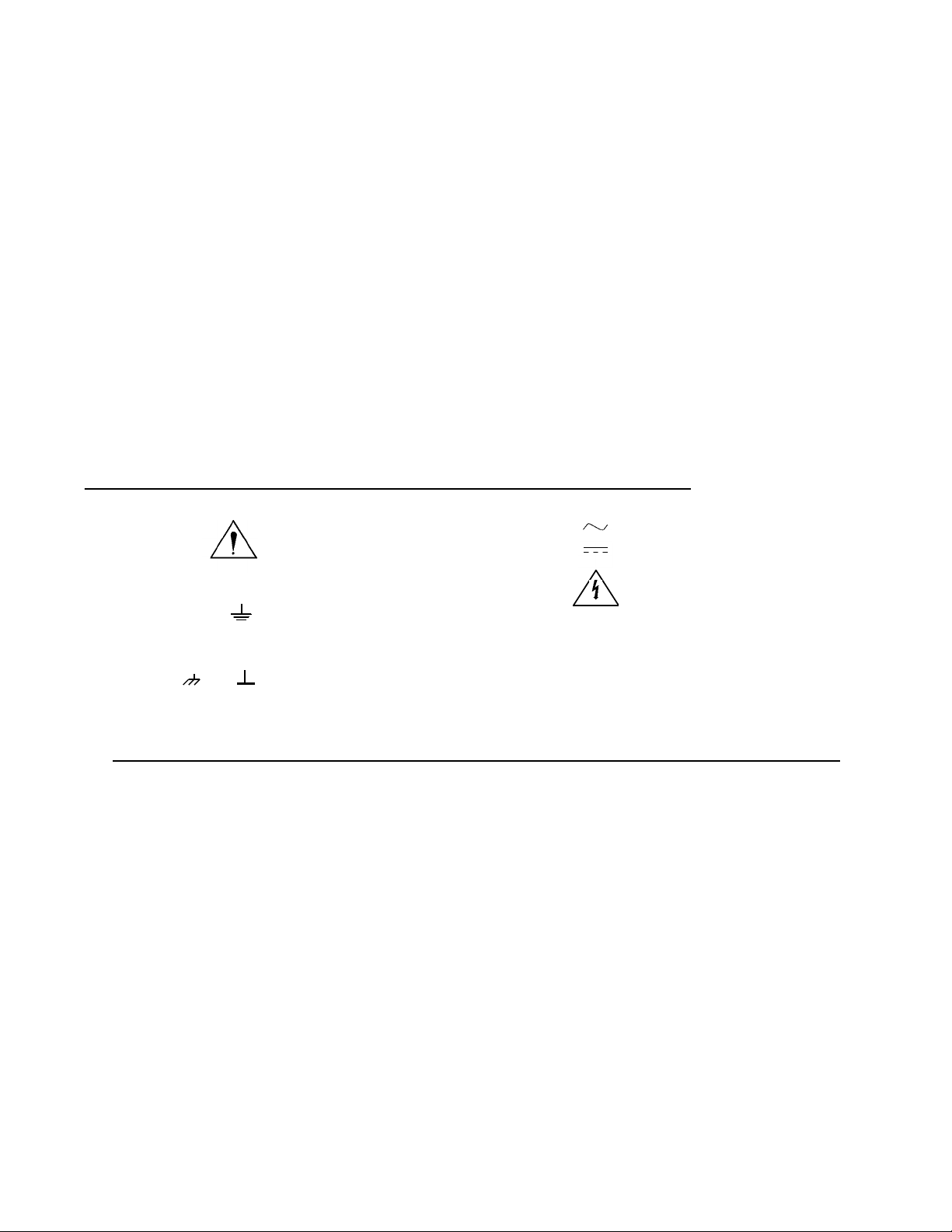
Safety Symbols
Printing History
Instruction
manual symbol
affixed to product. Indicates
Caution information to avoid personal injury or
damage to the
field wiring terminal that must be connected
to earth ground before operating the equip-
ment—protects against elect rical shock in
case of fault.
OR
that the user
must refer to
the manual
for specific
Warning or
product.
Indicates the
Frame or chassis ground tercally connects to
WARNING
CAUTION
Indicates
minal—typi
the equipment’s metal
frame.
Alternating
current (AC).
Direct current
(DC).
hazardous
voltages.
WARNINGS
The following general safety precautions must be observed during all phases of operation, service, and repair of this product. Failure to
comply with these precautions or with specific warnings elsewhere in this manual violates safety standards of design, manufacture, and
intended use of the product. Hewlett-Packard Company assumes no liability for the customer’s failure to comply with these requirements.
Ground the equipment: For Safety Class 1 equipment (equipment having a protective earth terminal), an uninterruptible safety earth ground
must be provided from the mains power source to the product input wiring terminals or supplied power cable.
DO NOT operate the product in an explosive atmosphere or in the presence of flammable gases or fumes.
For continued protection against fire, replace the line fuse(s) only with fuse(s) of the same voltage and current rating and type.
DO NOT use repaired fuses or short-circuited fuse holders.
Keep away from live circuits: Operating personnel must not remove equipment covers or shields. Procedures involving the removal of covers or
shields are for use by service-trained personnel only. Under certain conditions, dangerous voltages may exist even with the equipment switched
off. To avoid dangerous electrical shock, DO NOT perform procedures involving cover or shield removal unless you are qualified to do so.
DO NOT operate damaged equipment: Whenever it is possible that the safety protection features built into this product have been impaired,
either through physical damage, excessive moisture, or any other reason, REMOVE POWER and do not use the product until safe operation can
be verified by service-trained personnel. If necessary, return the product to a Hewlett-Packard Sales and Service Office for service and repair to
ensure that safety features are maintained.
DO NOT service or adjust alone: Do not attempt internal service or adjustment unless another person, capable of rendering first aid and resuscitation, is pr esent.
DO NOT substitute parts or modify equipment: Because of the danger of introducing additional hazards, do not install substitute parts or perform any unauthorized modification to the product. Return the product to a Hewlett-Packard Sales and Service Office for service and repair to ensure that safety features are maintained.
6
Page 7
What’s in this Manual
Manual Overview
This manual shows how to service the HP E1328A 4-Channel D/A Converter. Additional manuals which may
be required for servicing the D/A Converter include the HP E1328A User’s Manual which contains D/A
Converter operation, installation, and configuration information, and the appropriate mainframe user’s
manual(s) for mainframe operation, installation and configuration information.
Manual Content
Chapter Title Content
1
2
3
4
5
6
7
8
A
General
Information
Installation Procedures to install the D/A Converter, perform initial inspection,
Operating
Instructions
Verification
Tests
Adjustments Procedures to adjust the D/A Converter to within its rated
Replaceable
Parts
Manual
Changes
Service Procedures to aid in fault isolation and repair of the D/A Converter.
Calculating
D/A Converter
Accuracy
Provides a basic description, and lists available options and
accessories. Also lists the tools and test equipment required for
service.
prepare for use, and store and ship the D/A Converter.
Procedures to operate the D/A Converter and perform operator’s
check.
Functional verification, operation verification, and performance
verification tests to test the D/A Converter.
specifications.
Lists part numbers for user replaceable parts in the D/A Converter.
Provides information on ordering spare parts and module exchange.
Information to adapt this manual to instruments whose serial
numbers are lower than those listed on the title page.
Shows how D/A Converter accuracy, measurement uncertainty,
and test accuracy ratios (TARs) are calculated.
B
Verification
Tests - C
Programs
Gives example C programs to implement the the verification tests
and adjustments.
What’s in this Manual 7
Page 8
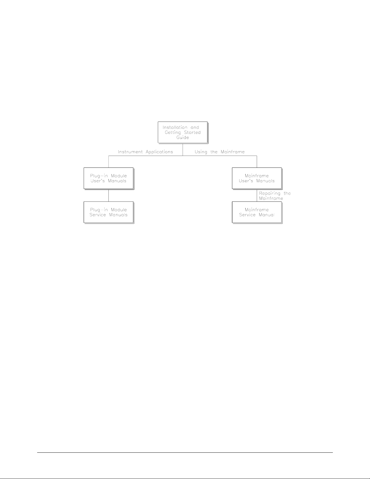
HP 75000 Series B Service Documentation
Suggested Sequence to Use Manuals
Manual Descriptions
Installation and Getting Started Guide. This manual contains step-by-step instructions for all aspects of
plug-in module and mainframe installation. Introductory programming information and examples are also
included.
Mainframe User’s Manual. This manual contains programming information for the mainframe, front panel
operation information ( for the HP E1301A mainframe) , and genera l programming information for instruments
installed in the main frame.
Plug-In Module User’s Manuals. These manuals contain plug-in module programming and configuration
information. Each manual contains examples for the most-used module functions, and a complete SCPI
command re fe re nc e fo r th e pl ug-in module.
Mainframe Service Manual. This manual contains service information for the mainframe. It contains
information for ordering replaceable parts and exchanging assemblies. Information and procedures for
performance verification, adjustment, preventive maintenance, troubleshooting, and repair are also included.
Plug-In Module Service Manuals. These manual s co nt ain pl ug -i n m od ul e se rv ic e in formation. Each m an u a l
contains information for exchanging the module and/or ordering replaceable parts. Depending on the module,
information and procedures for functional verification, operation verification, performance verification,
adjustment, preventive maintenance, troubleshooting, and repair are also provided.
8 HP 75000 Series B Ser vi ce D ocu m en ta ti o n
Page 9
Chapter 1
General Information
Introduction This HP E1328A Service Manual contains information required to test,
adjust, troubleshoot, and repair the HP E1328A B-Size VXI 4-Channel D/A
Converter (DAC). See the HP E1328A User’s Manual for additional
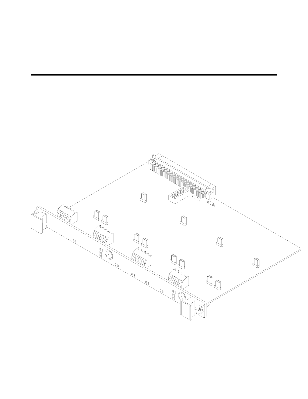
information on the HP E1328A DAC. Figure 1-1 shows the HP E1328A
DAC.
Figure 1-1. HP E1328A 4-Channel D/A Converter
Chapter 1 General Information 9
Page 10

Safety
Considerations
This product is a Safety Class I instrument that is provided with a protective
earth terminal when installed in the mainframe. The mainframe, DAC, and
all related documentation should be reviewed for familiarization with safety
markings and instructions before operation or service.
Refer to the WARNINGS page (page iii) in this manual for a summary of
safety information. Safety information for preventive maintenance, testing,
adjusting, and service follows and is also found throughout this manual.
Warnings and
Cautions
WARNING
This section contains WARNINGS which must be followed for your
protection and CAUTIONS which must be followed to avoid damage to the
equipment when performing instrument maintenance or repair.
SERVICE-TRAINED PERSONNEL ONLY. The information in
this manual is for service-trained personnel who are familiar
with electronic circuitry and are aware of the hazards involved.
To avoid personal injury or damage to the instrument, do not
perform procedures in this manual or do any servicing unless
you are qualified to do so.
CHECK MAINFRAME POWER SETTINGS. Before applying
power, verify that the mainframe setting matches the line
voltage and the correct fuse is installed. An uninterruptible
safety earth ground must be provided from the main power
source to the mainframe input wiring terminals, power cord, or
supplied power cord set.
GROUNDING REQUIREMENTS. Interruption of the protective
(grounding) conductor (inside or outside the mainframe) or
disconnecting the protective earth terminal will cause a
potential shock hazard that could result in personal injury.
(Grounding one conductor of a two-conductor outlet is not
sufficient protection.)
IMPAIRED PROTECTION. Whenever it is likely that instrument
protection has been impaired, the mainframe must be made
inoperative and be secured against any unintended operation.
REMOVE POWER IF POSSIBLE. Some procedures in this
manual may be performed with power supplied to the
mainframe while protective covers are removed. Energy
available at many points may, if contacted, result in personal
injury. (If maintenance can be performed without power
applied, the power should be removed.)
10 General Information Chapter 1
Page 11

USING AUTOTRANSFORMERS. If the mainframe is to be
energized via an autotransformer (for voltage reduction) make
sure the common terminal is connected to neutral (that is, the
grounded side of the main’s supply).
WARNING
CAUTION
CAPACITOR VOLTAGES. Capacitors inside the mainframe may
remain charged even when the mainframe has been
disconnected from its source of supply.
USE PROPER FUSES. For continued protection against fire
hazard, replace the line fuse(s) only with fuses of the same
current rating and type (such as normal blow, time delay, etc.).
Do not use repaired fuses or short-circuited fuseholders.
MAXIMUM VOLTAGE. Maximum voltage that may be applied
between any two terminals within the same channel is ± 15 Vdc. Do not
apply voltage between any pair of terminals if the D/A Converter is
turned off.
STATIC ELECTRICITY. Static electricity is a major cause of
component failure. To prevent damage to the electrical components in
the DAC, observe anti-static techniques when removing a DAC from
the mainframe or when working on the DAC. Also, when installing a
DAC in a mainframe slot, be sure to tighten the front panel screws.
POWER-UP/DOWN OUTPUTS. At power-up or down, potentials up
to 12V may appear across the channel outputs for up to 10 msec.
Chapter 1 General Information 11
Page 12

DAC
Description
The HP E1328A DAC is an "instrument" in the slots of a VXIbus
mainframe. As su ch, it is assigned an er ro r qu eue, input and ou tput buffers,
status registers, and is allocated a portion of mainframe memory for reading
storage.
NOTE
Instruments are based on the logical addresses of the plug-in modules. See
the HP 75000 Series B Installation and Getting Started Guide to set the
addresses to create an instrument.
There are two E1328A DAC functions (see Table 1-1):
• Isolated Voltage DACs
• Isolated Current DACs
Table 1-1. HP E1328A 4-Channel D/A Converter Functions
Function/
Feature
Voltage
DAC
Chs Description
1,2,3,4
Output DC voltage up to ± 10.92 V independently on
each channel. Can use remote voltage sensing w ith
"no-fault" operation. Connect multiple channels in
series to increase th e ou tp ut to ± 48 Vdc for a si ng le
module. All four channels are independently isolated
and may be floated up to 350 Vdc from ground. Each
channel can be calibrated electronically to 24-hour
specifications.
Current
DAC
1,2,3,4
Output DC current up to ± 21.8 mA independentl y on
each channel. Connect multiple channels in parallel
to increase the outp ut to ± 96 mA for a single module.
All four channels are independently isolated and may
be floated up to 350 Vdc from ground. Each channel
can be calibrat ed electronically to 24-hour
specifications.
DAC Specifications DAC specifications are listed in Appendix A of the HP E1328A Users
Manual. These sp ec ific ai ti on s ar e th e pe rf or mance standards or lim its
against which the instrument may be tested.
12 General Information Chapter 1
Page 13

DAC Serial
Numbers
DACs covered by this manual are identified by a serial number prefix listed
on the title page. Hewlett-Packard uses a two-part serial number in the form
XXXXAYYYYY, where XXXX is the serial prefix, A is the country of
origin (A = USA), and YYYYY is the serial suffix. The serial number
suffix is assigned sequentially to each instrument.
If the serial num b er pre fi x of yo u r in st ru me n t is gre at er th a n th e on e li st ed
on the title page , a M an ua l U pd at e (a s re qu ir ed ) w ill ex pl ain how to adapt
this manual to your instrument. If the serial number prefix is lower than the
one listed on the title page, information contained in Chapte r 7 - M an ua l
Changes explains how to adapt this manual to your instrument.
DAC Options There are no electrical or mechanical options available for the HP E1328A
DAC. However, you can order Option 1BN which provides a
MIL-STD-45662A Calibration Certificate, or Option 1BP which provides
the Calibration Certificate and measurement data. Contact your nearest
Hewlett-Packard Sales and Service Office for information on Options 1BN
and 1BP.
Chapter 1 General Information 13
Page 14

Recommended
Test Equipment
Table 1-2 lists the te st equipment recom m en ded for testing, adj us ti ng , and
servicing the HP E1328A DAC. Essential requirements for each piece of
test equipment are described in the Requirements column.
Table 1-2. Recommended Test Equipme nt
Instrument Requirements Recommended
Model
Controller, HP-IB HP-IB compatibility as def ined by IEEE
Standard 488-1978 and the identical
ANSI Standard MC1.1: SH1, AH1, T2,
TE0, L2, LE0, SR0, RL0, PP0, DC0, DT0,
and C1, 2, 3, 4, 5
Mainframe Compatible with DAC HP E1300A, E1301A,
DC Standard Voltage Range: -20.0 V to +20.0 V Datron 4708 with
Digital Mult im et er
*F = Functional Verification Tests, O = Operation Verification Tests, P = Performance Verification Tests,
A = Adjustments, T = Trou bl es hoooting
Voltage Range: ± 10 VDC
Current Range: ± 20 mA DC
Accuracy: ± (.015% reading + 1 mV)
± (.02% read ing + 1 µA)
HP 9000 Series 300
or
IBM compatib le PC with
HP BASIC
E1302A, or E1401B/T,
E1421A (requires HP
E1306A)
Option 10
HP 3458A multimeter
or
HP E1326B multimeter
Use*
A,F,O,
P,T
A,F,O,
P,T
F,O,P
A,F,O,
P,T
14 General Information Chapter 1
Page 15

Chapter 2
Installation
Introduction This chapter provides information to install the HP E1328A D/A Converter,
including initial inspection, preparation for use, environment, storage and
shipment.
Initial
Inspection
WARNING
Preparation for
Use
Inspect the shipping container for damage. If the shipping container or
cushioning material is damaged, keep the container until the shipment
contents have been checked and the instrument has been checked
mechanically and electrically. See Chapter 1 (Figure 1-1) for shipment
contents. See Chapter 4 for procedures to check electrical performance.
To avoid possible hazardous electrical shock, do not perform
electrical tests if there are signs of shipping damage to any
portion of the outer enclosure (covers, panels, etc.).
If the contents are incomplete, if there is mechanical damage or defect, or if
the instrument does not pass the electrical performance tests, notify your
nearest Hewlett-Packard Sales and Service Office. If the shipping container
is damaged or the cushioning material shows signs of stress, notify the
carrier as well as Hewlett-Packard, and keep the shipping materials for the
carrier’s inspection.
See Chapter 2 of the HP E1328A User’s Manual to prepare the
HP E1328A D/A Converter for use. See the appropriate mainframe user’s
manual(s) to prepare your mainframe. If your mainframe is not
manufactured by Hewlett-Pack a rd , co ns ul t th e m an uf ac tu re r fo r a list of
available manual(s).
Recommended operating environment for the HP E1328A D/A Converter is
o
C to +55oC with humidity <65% re la ti ve (0 oC to +40oC). The instrument
0
should be stored in a clean, dry environment. For storage and shipment, the
temperature range is -40
o
C to +40oC).
(0
Chapter 2 Installation 15
o
C to +75oC with humidity <65% relative humidity
Page 16
Shipping
Guidelines
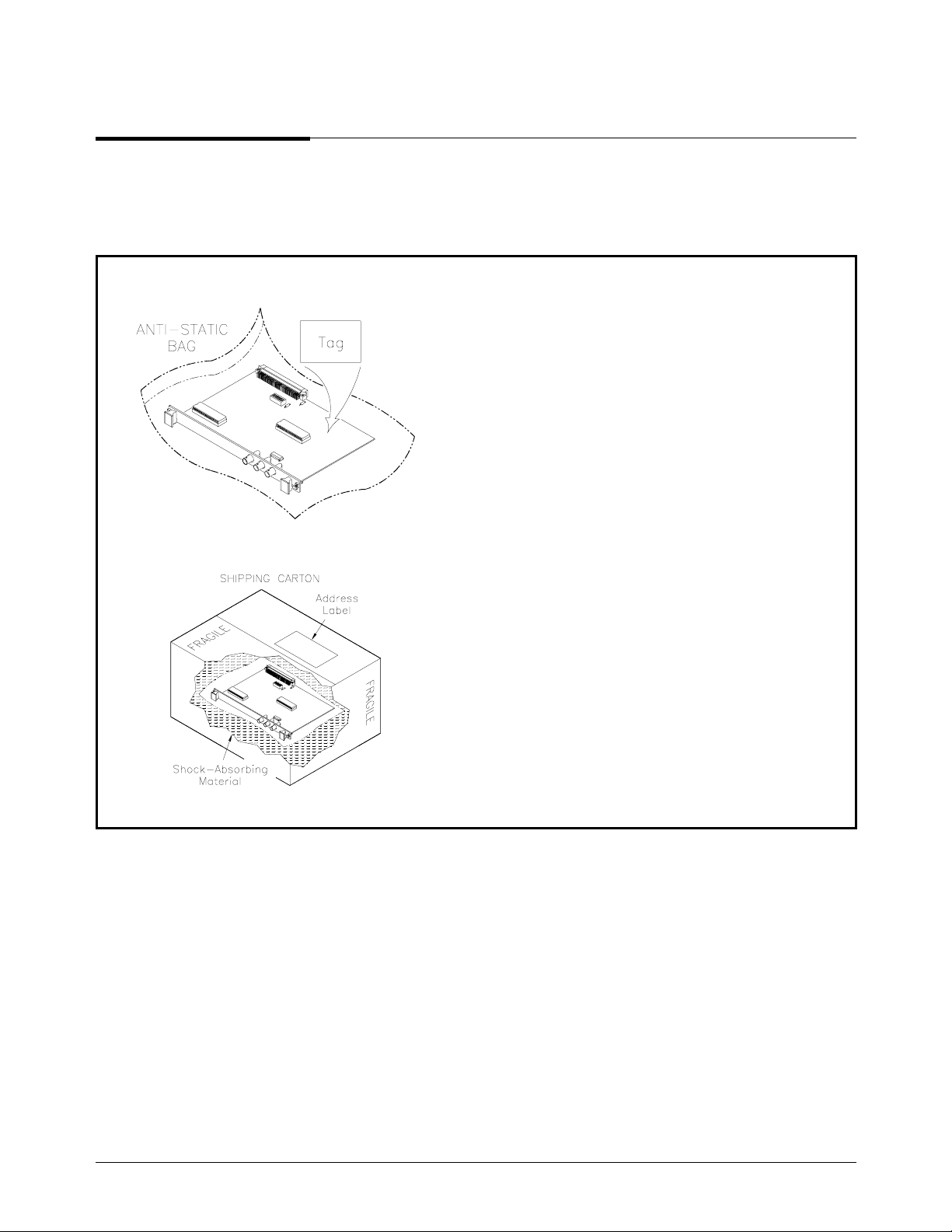
Follow the steps in Figure 2-1 to return the HP E1328A D/A Converter to a
Hewlett-Packard Sales and Support Office or Service Center.
1 Prepare the D/A Converter
•
Remove user wiring from the module
•
Attach tag to module/pod that identifies
- Owner
- Model Number/Serial Number
- Service Required
•
Place tagged device in approved anti-static bag
2 Package the D/A Converter
•
Place packaged D/A Converter in shipping carton*
•
Place 75 to 100 mm (3 to 4 inches) of shockabsorbing material around the D/A Converter
•
Seal the shipping carton securely
•
Mark the shipping carton FRAGILE
3 Ship the D/A Converter to Hewlett-Packard
•
Place address label on shipping carton
•
Send carton to Hewlett-Packard
Figure 2-1. Packaging/Shipping Guidelines
* We recommend that you use the same shipping materials as those used in factory packaging (available from Hewlett-Packard). For
other (commercially-available) shipping materials, use a double wall-carton with minimum 2.4 MPa (350 psi) test.
16 Installation Chapter 2
Page 17

Chapter 3
Operating Instructions
Introduction This chapter lists operating information for the HP E1328A D/A Converter,
including:
• D/A Converter operation
• Operator’s check (s elf- te st )
D/A Converter
Operation
Operator’s
Check
CAUTION
See the HP E1328A 4-Channel D/A Converter User’s Manual for D/A
Converter operation, including:
• Getting started
• Configuring the D/A Converter
• Using the D/A Converter
• Understanding the D/A Converter
• D/A Converter command reference
• D/A Converter specifications
• D/A Converter error messages
The Operator’s Check for the HP E1328A D/A Converter consists of
sending the self-test (*TST?) command and checking the return. The
operator’s check can be used at any time to verify the D/A Converter is
connected properly and is responding to the self-test command. See
Chapter 8 - Servic e for a list of D/A Converter self-test errors.
The *TST? command temporarily resets the D/A Converter (to
0 V or 0 A output) on each channel. Make sure any devices
connected to the DAC will not be adversely affected before
using *TST?.
As required, see the mainframe user’s manual for information on address
selection. See the HP E1328A User’s Manual for info rmation on D/A
Converter SCPI commands.
Chapter 3 Operating Instructions 17
Page 18

Self-Test Procedure 1. Verify the D/A Converter is properly installed in the mainframe and
the mainframe has passed its power-on sequence test. See the HP
75000 Series B System Installation and Getting Started Guide for
information on mainframe power-on sequence tests.
2. Execute the D/A Converter self-test using the *TST? command (see
example following).
3. A "0" returned means no self-test failure, while "-330" returned
means a failure was detected. See Chapter 8 - Service for trouble
shooting information (see NOTE following).
NOTE
Example: D/A
Converter Self-Test
Test failures can be caused by improper cabling, improper selection of the
interface select code, primary, and/or secondary address setting. Verify
proper connection and address selection before trouble shooting.
An example follows which uses an HP 9000 Series 300 computer with HP
BASIC and a D/A Converter address of 70909.
10 OUTPUT 70909;"*TST?" Send the self-test command
20 ENTER 70909;A Enter self-test result
30 PRINT A
40 END
18 Operating Instructions Chapter 3
Page 19

Chapter 4
Verification Tests
Introduction The three levels o f te st p ro ce du re s de sc ri be d in this chapter are us ed to
verify that the HP E1328A D/A Converter (DAC):
• is fully functional (Functional Verification)
• meets selected testable specifications (Operation Verification)
• meets all testable specifications (Performance Verification)
WARNING
Test Conditions /
Procedures
Do not perform any of the following verification tests unless
you are a qualified, service-trained person and have read the
WARNINGS and CAUTIONS in Chapter 1.
For valid tests, all test equipment and the HP 3458A multimeter must have a
one-hour warmup, the line voltage must be 115/230 Vac ± 10%, and HP
3458A ACAL must be performed no more than 24 hours before the tests.
See Table 1-2, Recommended Test Equipment for test equipment
requirements.
For best test accuracy, the ambient temperature of the test area should be
between 18°C and 28°C and stable to within ± 1°C. You should perform the
Performance Verification tests at least once a year. For heavy use or severe
operating environments, perform the tests more often.
The verification tests assume the person performing the tests understands
how to operate the mainframe, the DAC and specified test equipment. The
test procedures do not specify equipment settings for test equipment except
in general terms. It is assumed a qualified, service-trained person will select
and connect the cables, adapters, and probes required for the test.
Chapter 4 Verification Tests 19
Page 20

Performance Test
Record
Table 4-2, Performance Test Record for the HP E1328A DAC, at the end of
this chapter, pro v ide s space to enter the res ul ts of ea ch Perf or mance
Verification test and to compare the results with the upper and lower limits
for the test. You can make a copy of this form, if desired.
NOTE
Verification Test
Examples
The upper and lo wer limi ts in th e Per fo rm a nc e Tes t Rec or d as su m e th e te st
equipment used is calibrated and operating at peak performance. If this is
not the case/ problems can occur.
For example, an un ca lib ra ted HP 34 5 8A mul tim eter ma y ca us e wh a t seem s
to be an inaccurate measurement. This condition must be considered when
observed measurements do not agree with the performance test limits.
The value in the "Measurement Uncertainty" column of Table 4-2 is derived
from the specifications for the HP 3458A multimeter used for the test, and
represents the expected accuracy of the HP 3458A. The value in the "Test
Accuracy Ra tio (TA R) " col um n of Tab le 4-2 is th e ra ti o of DAC ac curacy
to HP 3458A measuremen t un cert aint y. If the TAR is ≤ 10:1, the ratio is
rounded to the nearest inte ge r. If the TAR is ≥ 10:1, the TAR is shown as
>10:1.
Each Performance Verification Test includes an example program to
perform the te st. Eac h ex am p le u se s ad dr es s 70 90 9 fo r th e D A C, an d an
HP 9000 Series 200/300 computer running HP BASIC commands. You
may need to change the DAC address and/or command syntax to perform
the examples for your setup.
As required, see the mainframe user’s manual for information on address
selection and cabling guidelines. See the HP E1328A User’s Manual for
information on Standard Commands for Programmable Instruments (SCPI
commands) for the DAC.
20 Verification Tests Chapt er 4
Page 21

Functional
Verification
Tests
DAC Self-Test This test verifies the DAC is communicating with the mainframe, external
The functional verification tests for the HP E1328A DAC can be performed
at any time to verify the DAC is functional and is communicating with the
mainframe , external comp ut er and /or external ter m in al . The fun ct io nal tests
for the HP E1328A DAC are:
• DAC Self-Test
• Voltage Compliance Tests (Optional)
• Current Compliance Tests (Optional)
controller, and/or external terminal by performing a self-test (*TST?
command). See "Operator’s Checks" in Chapter 3 for a description of the
DAC self-test.
Voltage
Compliance Tests
These OPTIONAL tests measure the voltage compliance on each channel of
the DAC.
Positive Voltage Compliance Tests
For positive voltage compliance tests, each channel to be tested is set for
UNCALIBRATED MAX voltage output (+ 12V). A DC source is
connected to V+ and S+ of the channel to be tested. The source is set to
+5V and increased in +0.5V steps until the channel output (as measured
with an HP 3458A multimeter) stops increasing. If the channel maximum
output is ≥ + 15V , th e te st pas se s.
Negative Voltage Compliance Tests
For negative voltage compliance tests, each channel to be tested is set for
UNCALIBRATED MIN voltage output (-12V). A DC source is connected
to V- and S- of the channel to be tested. The source is set to -5V and
increased in -0.5V steps until the channel output (as measured with an HP
3458A multimeter) stops increasing. If the channel minimum output is ≤
-15V, the te st p as se s.
Equipment Setup Connect the DC source (Datron 4708 with Option 10) and HP 3458A
multimeter to Channel 1 as shown in Figure 4-1. (Be sure to set all three
jumpers on the channel to the V position.) Set the DC source output to +5.0
V dc. Set the HP 3458A to DCV function and set NPLC 100.
Chapter 4 Verification Tests 21
Page 22

NOTE
For best measurement accuracy, perform an HP 3458A multimeter ACAL
not more than 24 hours prior to these tests.
Figure4-1. Voltage Compliance Test Connections
Test Procedure
(Positive Voltage
Compliance)
1. Set three jumpers on each channel to the V position
2. Connect DC Source and HP 3458A to Channel 1 (see Figure 4-1 )
3. Set non-cal mode on Channel 1 with CAL1:STAT OFF
4. Set Channel 1 to max voltage output ( + 12V) with VOLT1 MAX
5. Set DC source to + 5V and measure channel output (in V)
6. Increase DC so ur ce out pu t by +0. 5 V an d m ea su re new ch an ne l ou tput
(in V)
7. Repeat step 6 until channel output stops increasing. If the output voltage
is ≥ + 15.0V when the output stops increasing, the test passes.
8. Repeat steps 2 through 7 for Channels 2, 3, and 4 (use CALchan: STAT
OFF and VOLTchan MAX)
9. Remove power and disconnect test equipment
22 Verification Tests Chapt er 4
Page 23

Test Procedure
(Negative Voltage
Compliance)
1. Set three jumpers on each channel to the V position
2. Connect DC Source and HP 3458A to Channel 1 (see Figure 4-1 )
3. Set non-cal mode on Channel 1 with CAL1:STAT OFF
4. Set Channel 1 to min voltage output (-12V) with VOLT1 MIN
5. Set DC source to -5V and measure channel output (in V)
6. Increase DC source output by -0.5V and measure new channel output
(in V)
7. Repeat step 6 until channel output stops increasing. If the output
voltage is ≤ -15.0V when the output stops increasing, the test passes.
8. Repeat steps 2 through 7 for Channels 2, 3, and 4 (use CALchan:
STAT OFF and VOLTchan MIN)
9. Remove power and disconnect test equipment
Example: Positive
Voltage Compliance
NOTE
This program checks the MEASURED voltage output from the DAC
channel being tested. If the measured channel output is ≥ 15.0V when the
output stops increasing, the program generates a "test PASSED" indication.
If the measured channel output is < 15.0V when the output stops increasing,
the program generates a "test FAILED" indication.
To use this program for negative voltage compliance tests, change the
indicated lines as shown:
50 OUTPUT 70909;"VOLT"&VAL$(Chan)&" MIN"
60 Source = -4.5
90 Source = Source-.5
180 IF Value <= -15 THEN Pass$ = "PASSED"
190 IF Value > -15 THEN Pass$ = "FAILED"
Chapter 4 Verification Tests 23
Page 24

10 ! Positive Voltage Compliance Tests
20 !
30 FOR Chan = 1 TO 4
40 OUTPUT 70909;"CAL"&VAL$(Chan)&":STAT OFF"
50 OUTPUT 70909;"VOLT"&VAL$(Chan)&" MAX"
60 Source = 4.5
70 REPEAT
80 PRINT TABXY(1,1),"Voltage Compliance Tests on Channel";Chan
90 Source = Source + .5
100 Old_value = Value
110 PRINT TABXY(4,9),"Set source to ";Source;"Volts DC "
120 PRINT TABXY(4,10),"Measure channel output (in V) "
130 INPUT " Enter channel output (in V) ",Value
140 PRINT TABXY(4,5),"DC Source value = ";Source;"VDC "
150 PRINT TABXY(4,6),"Channel";Chan;"output = ";Value;"VDC "
160 Result = Value-Old _value
170 UNTIL Result = 0
180 IF Value >= 15 THEN Pass$ = "PASSED"
190 IF Value < 15 THEN Pass$ = "FAlLED"
200 CLEAR SCREEN
210 PRINT TABXY(1,8),"Maximum Channel";Chan;"output =
";Value;"Volts"
220 PRINT TABXY(1,9),"Test ";Pass$;" for Channel";Chan
230 DISP " Press Continue for next channel"
240 PAUSE
250 CLEAR SCREEN
260 NEXT Chan
270 END
Current
Compliance
Tests
These tests mea su re the cur ren t com p li an ce on ea ch cha nn el of th e D A C.
Positive Current Compliance Tests
For positive current compliance tests, each channel to be tested is set for
UNCALIBRATED MAX current output (+24 mA). A DC source and
HP 3458A are connected to the channel to be tested. The source is set to
+ 12V and increa se d in + 0.5 V step s unt il the cha nnel output decrea se s to
90% of the maximum current value (decreases to +21.6 mA). If the DC
SOURCE voltag e is ≥ + 13 V wh en the chan n el out pu t de crea se s to 90 % of
maximum cu rr en t th e te st p as se s.
24 Verification Tests Chapt er 4
Page 25

Negative Current Compliance Tests
For negative current compliance tests each channel to be tested is set for
UNCALIBRATED MIN current output (-24 mA). A DC source and
HP 3458A are connected to the channel to be tested. The source is set to
-12V and increased in -0.5V steps until the channel output decreases to 90%
of the maximum current value (decreases to -21.6 mA). If the DC SOURCE
voltage is ≤ -13V when the channel output decreases to 90% of maximum
current, the test passes.
Equipment Setup Connect the DC source (Datron 4708 with Option 10) and HP 3458A
multimeter to Channel 1 as shown in Figure 4-2. (Be sure to set all three
channel jumpers to the I position.) Then, set the DC source output to
+12.0 Vdc. Set the HP 3458A to DCI function and set NPLC 100.
NOTE
For best measurement accuracy, perform an HP 3458A multimeter ACAL
not more than 24 hours prior to these tests.
Figure 4-2. Current Compliance Test Connections
Chapter 4 Verification Tests 25
Page 26

Test Procedure
(Positive Current
Compliance)
1. Set three jum pe rs o n ea ch ch a nn el to the I position
2. Connect source and HP 3458A to Channel 1 (see Figure 4-2)
3. Set non-cal mode on Channel 1 with CAL1:STAT OFF
4. Set Channel 1 max output (+24 mA) with CURR1 MAX
5. Set DC source to + 12.0V and measure channel output (in mA)
6. Increase DC source output by +0.5V and measure channel output (in mA)
7. Repeat step 6 until channel output is 90% of max (21.6 mA). If the
SOURCE voltag e is ≥ 13.0V when the output decreases to 90% of max, the
test passes.
8. Repeat steps 2 through 7 for Channels 2, 3, and 4. (Use CALchan:STAT
OFF and CURRchan MAX.)
Test Procedure
(Negative Current
Compliance)
9. Remove power and disconnect test equipment
1. Set three jum pe rs o n ea ch ch a nn el to the I position
2. Connect source and HP 3458A to Channel 1 (see Figure 4-2)
3. Set non-cal mode on Channel 1 with CAL1:STAT OFF
4. Set Channel 1 min current output (-24 mA) with CURR1 MIN
5. Set DC source to -12.0V and measure channel output (in mA)
6. Increase DC source output by -0.5V and measure channel output (in mA)
7. Repeat step 6 until channel output is 90% of min (-21.6 mA). If the
SOURCE voltag e is ≤ -13.0V when the output decreases to 90% of min, the
test passes.
8. Repeat steps 2 through 7 for Channels 2, 3, and 4 (use CAL chan:STAT
OFF and CURR chan MIN)
26 Verification Tests Chapt er 4
Page 27

9. Remove power and disconnect test equipment
Example: Positive
Current Compliance
NOTE
This program checks the MEASURED current output from the DAC
channel being tested. If the DC SOURCE voltage is ≥ 13.0V when the
output current drops to 90% of maximum current, the program generates a
"test PASSED" indication. If the DC SOURCE voltage is < 13.0V when the
output current drops to 90% of maximum current, the program generates a
"test FAILED" indication.
To use this program for negative current compliance tests, change the
indicated lines as shown:
50 OUTPUT 70909;"CURR"&VAL$(Chan)&" MIN"
60 Source = -11.5
90 Source = Source-.5
180 IF Source <= -13.0 THEN Tst$="PASSED"
190 IF Source > -13.0 THEN Tst$ ="FAILED"
10 ! Current Compliance Tests
20 !
30 FOR Chan = 1 TO 4
40 OUTPUT 70909;"CAL"&VAL$(Chan)&":STAT OFF"
50 OUTPUT 70909;"CURR"&VAL$(Chan)&" MAX"
60 Source = 11.5
70 REPEAT
80 PRINT TABXY(1,1),"Current Compliance Tests on Channel";Chan
90 Source = Source + .5
100 PRINT TABXY(4,10),"Set DC source to ";Source;"Volts DC "
110 PRINT TABXY(4,11),"Measure channel output (in mA)"
120 INPUT " Enter channel output (in mA) ",Value
130 Result = ABS(100*Value/24.0)
140 PRINT TABXY(4,5),"DC Source value = ";Source;"VDC "
150 PRINT TABXY(4,6),"Channel";Chan;"output = ";Value;"mA"
160 PRINT TABXY(4,7),"Output = ";Result;"% of max value "
170 UNTIL Result <= 90.0
180 IF Source >= 13.0 THEN Tst$ = "PASSED"
190 IF Source < 13.0 THEN Tst$ = "FAILED"
200 CLEAR SCREEN
210 PRINT TABXY(4,14),"DC Source value for output 90% of max =
";Source;"VDC"
220 PRINT TABXY(4,15),"Test ";Tst$;" for Channel";Chan
230 NEXT Chan
240 END
Chapter 4 Verification Tests 27
Page 28

Operation
Verification
Tests
Operation verification tests objectives are to instill a high degree of
confidence that the HP E1328A 4-Channel D/A Converter is meeting
selected specifications from those listed in Appendix A - Specifications in
the HP E1328A User’s Manual.
Operation verification tests can be used in applications such as incoming
inspection and af te r HP E132 8A re pa ir. To pe rf or m o pe ratio n verif icat io n
tests, do the parts of the performance verification tests shown in Table 4-1.
See Performance Verification Tests for details on the test procedures.
NOTE
For best results, pe rfor m an ACAL on th e HP 3 45 8A mul tim et er n ot mo re
than 24 hours prior to performing the operation verification tests.
If the operation verification test FAILS on any channel, you may want to
perform the Voltage Adjustment and/or Current Adjustment procedures in
Chapter 5 - Adjustments and then rerun the operation verification tests.
Table 4-1. HP E1328A DAC Operation Verification Tests
For this test: Make these measurements:
Voltage Accuracy -10V, 0V, +10V
Current Accuracy -20 mA, 0 mA, +20 mA
28 Verification Tests Chapt er 4
Page 29

Performance
Verification
Tests
Performance verification tests objectives are to instill a high degree of
confidence that the HP E1328A 4-Channel D/A Converter (DAC) is
meeting the specifications listed in Appendix A - Specifications of the HP
E1328A User’s Manual. Performan ce ver if icat io n te st s ar e re qu ir ed
whenever a calibration is required. The HP E1328A DAC performance
verificatio n te st s ar e:
• Voltage Accuracy Measurements
• Current Accuracy Measurements
NOTE
Voltage Accuracy
Measurements Test
Equipment setup Connect the equipment as shown in Figure 4-3. Be sure the three jumpers in
For best results you should ACAL the HP 3458A multimeter not more than
24 hours prior to the tests. If a DAC channel does not pass the performance
tests, you may want to do the Voltage Adjustment and/or Current
Adjustment (see Chapter 5 - Adjustments) and then rerun the performance
verification tests.
This test checks voltage output accuracy on Channels 1, 2, 3, and 4 of the
DAC. The voltage output levels checked are: -10V, -8V, -5V, -2V, 0V,
+2V, +5V, +8V, and +10V.
each DAC channel are set to the V (voltage) position. Then, set the HP
3458A to DCV function and set NPLC 100.
Figure 4-3. Voltage Accuracy Measurements Connections
Chapter 4 Verification Tests 29
Page 30

NOTE
The value of 1 kΩ in Figure 4-3 is the factory value used for original
measurements. If you previously calibrated your DAC with a different
resistance value, use that resistance value rather than 1 kΩ .
Test Procedure 1. Set three jumpers on each channel to the V position
2. Connect HP 3458A and 1 kΩ resistor to Channel 1 (see Figure 4-3)
3. Set HP E1328A DAC to default with *RST
4. Set Channel 1 to calibrated mode with CAL1:STAT ON
5. Output -10V on Channel 1 with VOLT1 -10.0000
6. Measure Channel 1 output voltage with HP 3458A and compare
with limits in Table 4-2
7. Repeat steps 5 and 6 for -8V, -5V, -2V, 0V, +2V, +5V, +8V, and
+10V
Example: Voltage
Accuracy
Measurements
8. Repeat steps 2 through 7 for Cha nn el s 2, 3, an d 4 (u se
CALchan:STAT ON and VOLTchan value)
9. Remove power and disconnect test equipment
This program checks the MEASURED output voltage on each DAC
channel and compares the result with the 1-year accuracy specifications for
the DAC (see Appendix A - Calculating D/A Converter Accuracy for a
discussion of DAC accuracy).
10 ! Voltage Accuracy Measurements Test
20 !
30 OPTION BASE 1
40 DIM Volts(4,9)
50 DATA -10,-8,-5,-2,0,2,5,8,10
60 DATA -10,-8,-5,-2,0,2,5,8,10
70 DATA -10,-8,-5,-2,0,2,5,8,10
80 DATA -10,-8,-5,-2,0,2,5,8,10
90 READ Volts(*)
100 OUTPUT 70909;"*RST"
110 FOR Chan = 1 TO 4
120 FOR I = 1 TO 9
130 OUTPUT 70909;"VOLT"&VAL$(Chan)&" ";Volts(Chan,I)
140 PRINT TABXY(1,2),"Voltage Accuracy Measurements on Channel
";Chan
30 Verification Tests Chapt er 4
Page 31

150 PRINT TABXY(1,10),"New voltage output on Channel";Chan;" =
":Volts(Chan,I);"V "
160 PRINT
170 INPUT " Enter MEASURED voltage value (in V) ",Meas(Chan,I)
180 GOSUB Accuracy
190 Accuracy: !
200 Acc(Chan,I) = .0035*ABS(Volts(Chan,I)) + .11334
210 Llim(Chan,I) = Volts(Chan,I) - Acc(Chan,I)
220 Ulim(Chan,I) = Volts(Chan,I) + Acc(Chan,I)
230 IF Meas(Chan,I) < Llim(Chan,I) OR Meas(Chan,I) > Ulim(Chan,I)
THEN
240 PRINT TABXY(1,9),"Test FAILED on Channel";Chan;"for
";Volts(Chan,I);"V"
250 ELSE
260 PRINT TABXY(1,9),"Test PASSED on Channel";Chan;"for
";Volts(Chan,I);"V "
270 END IF
280 NEXT I
290 NEXT Chan
300 PRINT TABXY(1,18) ,"Voltage Accuracy Tests Complete"
310 END
Counter Accuracy
Measurements Test
Equipment Setup Connect the equipment as shown in Figure 4-4. Be sure the three jumpers
This test checks current output accuracy on Channels 1, 2, 3, and 4 of the
DAC. The current output levels checked are: -20 mA, -16 mA, -10 mA, -4
mA, 0 mA, 4 mA, 10 mA, 16 mA, and 20 mA.
in each DAC chan ne l ar e se t to the I (cu rr en t) p os itio n. Th en , se t th e
HP 3458A to DCI function and set NPLC 100.
Figure 4-4. Current Measurement Accuracy Connections
Chapter 4 Verification Tests 31
Page 32

NOTE
The value of 500 Ω in Figure 4-4 is the factory value used for original
measurements. If you previously calibrated your DAC with a different
resistance value, use that resistance value rather than 500 Ω .
Test Procedure 1. Set three jumpe rs on ea ch ch a nn el to th e I po si tion
2. Connect HP 3458A and 500 Ω resistor to Channel 1 (see Figure 4-4)
3. Set HP E1328A DAC to default with *RST
4. Set Channel 1 to calibrated mode with CAL1:STAT ON
5. Output -20 mA on Channel 1 with CURR1 -.02000
6. Measure Channel 1 output current with HP 3458A and compare with
limits in Table 4-2
7. Repeat steps 5 and 6 for -16 mA, -10 mA, -4 mA, 0 mA, 4 mA, 10
mA., 16 mA, and 20 mA
Example: Current
Accuracy
Measurements
8. Repeat steps 2 through 7 for Channels 2, 3, and 4 (use CALchan:
STAT ON and CURRchan value)
9. Remove power and disconnect test equipment
This program checks the MEASURED output current on each DAC channel
and compares the result with the 1-year accuracy specifications for the DAC
(See Appendix A - Calculating D/A Converter Accuracy for a discussion of
DAC accura cy ).
10 ! Current Accuracy Measurements Test
20 !
30 OPTION BASE 1
40 DIM Amps(4,9)
50 DATA -.02,-.016,-.01,-.004,0,.004,.01,.016,.02
60 DATA -.02,-.016,-.01,-.004,0,.004,.01,.016,.02
70 DATA -.02,-.016,-.01,-.004,0,.004,.01,.016,.02
80 DATA -.02,-.016,-.01,-.004,0,.004,.01,.016,.02
90 READ Amps(*)
100 OUTPUT 70909;"*RST"
110 FOR Chan = 1 TO 4
120 FOR l=1 TO 9
130 OUTPUT 70909;"CURR"&VAL$(Chan)&" ";Amps(Chan,I)
140 PRINT TABXY(1,2)," Current Accuracy Measurements on Channel
";Chan
32 Verification Tests Chapt er 4
Page 33

150 PRINT TABXY(1,10),"New current output on Channel";Chan;" =
";Amps(Chan,I)*1.E + 3;"mA "
160 INPUT " Enter MEASURED current value (in mA) ",Meas(Chan,I)
170 GOSUB Accuracy
180 Accuracy: !
190 Acc(Chan,I) = .0035*ABS(Amps(Chan,I)) + 2.2665E-4
200 Llim(Chan,I) = Amps(Chan,I) - Acc(Chan,I)
210 Ulim(Chan,I) = Amps(Chan,I) + Acc(Chan,I)
220 IF Meas(Chan,I)*1.E-3 < (Chan,I) OR Meas(Chan,I)*1.E-3 >
Ulim(Chan,I) THEN
230 PRINT TABXY(1,9),"Test FAILED on Channel";Chan;"for
";Amps(Chan,I)*1.E + 3;"mA "
240 ELSE
250 PRINT TABXY(1,9),"Test PASSED on Channel";Chan;"for
";Amps(Chan,I)*1.E + 3;"mA "
260 END IF
270 NEXT I
280 NEXT Chan
290 PRINT TABXY(1,18),"Current Accuracy Tests Complete"
300 END
Performance
Test Record
NOTE
Table 4-2, Performance Test Record for the HP E1328A DAC, can be used
to record the res ul ts of ea ch Op erat io n V er ific at io n an d Per fo rma nc e
Verification test for the HP E1328A DAC (this record can be copied if
desired). The record includes the DAC upper and lower limits, HP 3458A
measurement uncertainty, and the Test Accuracy Ratio (TAR) for the test.
The values for DAC accuracy, HP 3458A measurement uncertainty and
TAR in Table 4-2 assume the following conditions. If your test conditions
differ from thes e co nd it io ns , you will need to compu te the app ro pr ia te
values.
• Calibration ON state (CAL x :STAT O N) fo r ea ch channel
• 1 kΩ load for voltage accuracy measurements
• 500 Ω load for current accuracy measurements
• Test temp ASSUMED to be ± 5° C different than cal temp
• 1-year specifications for DAC accuracy
• 1-year specifications for HP 3458A meas uncertainty
For the conditions listed, all Test Accuracy Ratios (TARs) exceed 4:1
Chapter 4 Verification Tests 33
Page 34

Table 4-2. Performance Test Record for the HP E1328A DAC (Page 1 of 3)
Test Facility:
Name ____________ __ __ ______________ _______
Address ________ __ __ ______________ __ _________
City/State ___________________________________
Phone __________ __ __ __ ______________ __ _____
Special Notes:
____________________________________________________________________________________________
____________________________________________________________________________________________
____________________________________________________________________________________________
____________________________________________________________________________________________
____________________________________________________________________________________________
____________________________________________________________________________________________
Report No. __________________________________
Date ______________________ __ ______________ _
Customer ___________________________________
Tested by __________________________________
Test Equipment Record
Model __________ __ __ __ ___________ Report No. ______________ __ ____ Date _________ __ __ __ __ _____
Test Equipment Used:
Description Model No. Trace No. Cal Due Date
1. ____________ ___________________
2. ____________ ___________________
3. ____________ ___________________
4. ____________ ___________________
5. ____________ ___________________
6. ____________ ___________________
7. ____________ ___________________
______________
______________
______________
______________
______________
______________
______________
______________
______________
______________
______________
______________
______________
______________
______________
______________
______________
______________
______________
______________
______________
34 Verification Tests Chapt er 4
Page 35

Table 4-2. Performance Test Record for the HP E1328A DAC (Page 2 of 3)
Voltage Accuracy Measurements*
Ch Output
Value (V)
1
-10.00000
1
1
1
1
1
1
1
1
2
2
2
2
2
2
2
2
2
3
3
3
3
3
3
3
3
3
-8.00000
-5.00000
-2.00000
0.00000
+2.00000
+5.00000
+8.00000
+10.00000
-10.00000
-8.00000
-5.00000
-2.00000
0.00000
+2.00000
+5.00000
+8.00000
+10.00000
-10.00000
-8.00000
-5.00000
-2.00000
0.00000
+2.00000
+5.00000
+8.00000
+10.00000
Low
Limit (V)
-10.14833
-8.14134
-5.13084
-2.12033
-.11334
+1.87967
+4.86916
+7.85867
+9.85167
-10.14833
-8.14134
-5.13084
-2.12033
-.11334
+1.87967
+4.86916
+7.85867
+9.85167
-10.14833
-8.14134
-5.13084
-2.12033
-.11334
+1.87967
+4.86916
+7.85867
+9.85167
Measured Value
(V)
__________________
__________________
__________________
__________________
__________________
__________________
__________________
__________________
__________________
__________________
__________________
__________________
__________________
__________________
__________________
__________________
__________________
__________________
__________________
__________________
__________________
__________________
__________________
__________________
__________________
__________________
__________________
High
Limit (V)
-9.85167
-7.85867
-4.86916
-1.87967
+.11334
+2.12033
+5.13084
+8.14134
+10.14833
-9.85167
-7.85867
-4.86916
-1.87967
+.11334
+2.12033
+5.13084
+8.14134
+10.14833
-9.85167
-7.85867
-4.86916
-1.87967
+.11334
+2.12033
+5.13084
+8.14134
+10.14833
Measurement
Uncertainty (
103.60
103.60
103.60
103.60
103.60
103.60
µV)
83.30
52.85
22.40
2.10
22.40
52.85
83.30
83.30
52.85
22.40
2.10
22.40
52.85
83.30
83.30
52.85
22.40
2.10
22.40
52.85
83.30
Test Acc
Ratio (TAR)
>10:1
>10:1
>10:1
>10:1
>10:1
>10:1
>10:1
>10:1
>10:1
>10:1
>10:1
>10:1
>10:1
>10:1
>10:1
>10:1
>10:1
>10:1
>10:1
>10:1
>10:1
>10:1
>10:1
>10:1
>10:1
>10:1
>10:1
4
4
4
4
4
4
4
4
4
-10.00000
-8.00000
-5.00000
-2.00000
0.00000
+2.00000
+5.00000
+8.00000
+10.00000
-10.14833
-8.14134
-5.13084
-2.12033
-.11334
+1.87967
+4.86916
+7.85867
+9.85167
__________________
__________________
__________________
__________________
__________________
__________________
__________________
__________________
__________________
-9.85167
-7.85867
-4.86916
-1.87967
+.11334
+2.12033
+5.13084
+8.14134
+10.14833
103.60
83.30
52.85
22.40
2.10
22.40
52.85
83.30
103.60
>10:1
>10:1
>10:1
>10:1
>10:1
>10:1
>10:1
>10:1
>10:1
* 1-year DAC and HP 3458A specifications
±5°C temp difference from cal temperature
HP 3458A ACAL within previous 24-hours
Chapter 4 Verification Tests 35
Page 36

Table 4-2. Performance Test Record for the HP E1328A DAC (Page 3 of 3)
Current Accuracy M ea sur eme n ts*
Ch Output
Value (mA)
1
-20.00000
1
-16.00000
1
-10.00000
1
1
1
1
1
1
2
2
2
2
2
2
2
2
2
3
3
3
3
3
3
3
3
3
-4.00000
0.00000
+4.00000
+10.00000
+16.00000
+20.00000
-20.00000
-16.00000
-10.00000
-4.00000
0.00000
+4.00000
+10.00000
+16.00000
+20.00000
-20.00000
-16.00000
-10.00000
-4.00000
0.00000
+4.00000
+10.00000
+16.00000
+20.00000
Low Limit
(mA)
-20.29665
-16.28265
-10.26165
-4.24065
-.22665
+3.75935
+9.73835
+15.71735
+19.70335
-20.29665
-16.28265
-10.26165
-4.24065
-.22665
+3.75935
+9.73835
+15.71735
+19.70335
-20.29665
-16.28265
-10.26165
-4.24065
-.22665
+3.75935
+9.73835
+15.71735
+19.70335
Measured Val u e
(mA)
____________ ____
____________ ____
____________ ____
____________ ____
____________ ____
____________ ____
____________ ____
____________ ____
____________ ____
____________ ____
____________ ____
____________ ____
____________ ____
____________ ____
____________ ____
____________ ____
____________ ____
____________ ____
____________ ____
____________ ____
____________ ____
____________ ____
____________ ____
____________ ____
____________ ____
____________ ____
____________ ____
High Limit
(mA)
-19.70335
-15.71735
-9.73835
-3.75935
+.22665
+4.24065
+10.26165
+16.28265
+20.29665
-19.70335
-15.71735
-9.73835
-3.75935
+.22665
+4.24065
+10.26165
+16.28265
+20.29665
-19.70335
-15.71735
-9.73835
-3.75935
+.22665
+4.24065
+10.26165
+16.28265
+20.29665
Meas Uncert
(µA)
1.440
1.272
.330
.168
.060
.168
.330
1.272
1.440
1.440
1.272
.330
.168
.060
.168
.330
1.272
1.440
1.440
1.272
.330
.168
.060
.168
.330
1.272
1.440
Test Acc
Ratio (TAR)
>10:1
>10:1
>10:1
>10:1
>10:1
>10:1
>10:1
>10:1
>10:1
>10:1
>10:1
>10:1
>10:1
>10:1
>10:1
>10:1
>10:1
>10:1
>10:1
>10:1
>10:1
>10:1
>10:1
>10:1
>10:1
>10:1
>10:1
4
4
4
4
4
4
4
4
4
-20.00000
-16.00000
-10.00000
-4.00000
0.00000
+4.00000
+10.00000
+16.00000
+20.00000
-20.29665
-16.28265
-10.26165
-4.24065
-.22665
+3.75935
+9.73835
+15.71735
+19.70335
____________ ____
____________ ____
____________ ____
____________ ____
____________ ____
____________ ____
____________ ____
____________ ____
____________ ____
-19.70335
-15.71735
-9.73835
-3.75935
+.22665
+4.24065
+10.26165
+16.28265
+20.29665
1.440
1.272
.330
.168
.060
.168
.330
1.272
1.440
>10:1
>10:1
>10:1
>10:1
>10:1
>10:1
>10:1
>10:1
>10:1
* 1-year DAC and HP 3458A specifications
±5°C temp difference from cal temperature
HP 3458A ACAL within previous 24-hours
36 Verification Tests Chapt er 4
Page 37

Chapter 5
Adjustments
Introduction This chapter contains procedures to adjust the HP E1328A D/A Converter
(DAC), including voltage adjustments and current adjustments.
The DAC should be adjusted after repair to ensure peak performance.
Equipment required for the adjustment procedures is listed in Table 1-2,
Recommended Test Equipment.
Before performing adjustments, the DAC must have a minimum 60-minute
warm up and the line voltage must be 115/230 Vac ± 10%. For best
accuracy, the test area temperature should be between 18°C and 28°C, and
stable to ± 1°C.
WARNING
Voltage
Adjustments
Do not perform any of the following adjustments unless you are
a qualified, service trained person and have read the
WARNINGS and CAUTIONS in Chapter 1.
This adjustment is used to update the stored voltage constants for each DAC
channel, and should be perfomed:
• On initial setup
• Periodically (24 hours or 90 days) to maintain specified output accuracy
(see Appendix A - Specifications of the HP E1328A User’s Manual)
• When temperature has changed more than ± 5°C from last adjustment
temperature
• When the type of load is changed
• Any time accuracy is in d ou bt
Chapter 5 Adjustments 37
Page 38

NOTE
For best measurement accuracy, perform an HP 3458A multimeter ACAL
not more than 24 hours prior to these adjustments. Each DAC channel to
be adjusted MUST be in the non-calibrated mode (CALx:STAT OFF), or
errors in the adjustment constants will occur.
Equipment Setup
NOTE
Connect a 1 kΩ resistor and HP 3458A multimeter to the channel to be
adjusted, as shown in figure 5-1. Be sure to set all three channel jumpers to
the V (voltage) position. Set the HP 3458A to DCV function and set NPLC
100.
The value of 1 kΩ in Figure 5-1 is the factory value used for original
adjustments. If you previously adjusted your DAC with a different
resistance value, use that resistance value rather than 1 kΩ .
Figure 5-5. Voltage Adjustment Connections
38 Adjustments Chapter 5
Page 39

Adjustment
Procedures
1. Set three jumpers on Channel 1 to the V position.
2.
Connect a 1 kΩ resistor and HP 3458A to Channel 1 (see Figure
5-1).
3. Set Channel 1 to non-calibrated mode with CAL1:STAT OFF.
4. Set Channel 1 to minimum output (-12V) with VOLT1 MIN.
Measure and record to 5 1/2 digits the actual output voltage.
5. Set Channel 1 to default output (0V) with VOLT1 DEF. Measure
and record to 5 1/2 digits the actual output voltage.
6. Set Channel 1 to maximum output (+12V) with VOLT1 MAX.
Measure and record to 5 1/2 digits the actual output voltage.
7. Enter recorded minimum, default, and maximum values with
CAL1:VOLT min,def,max. The adjustment constants are
automatica lly up da te d and stored.
8. Repeat steps 1 through 7 for channels 2, 3, and 4 as desired (use
CALchan:STAT OFF, VOLTchan value, and CALchan:VOLT
values).
9. Remove power and disconnect power equipment.
Example: Voltage
Adjustments
This program uses the measured minimum, default, and maximum values
you enter to update the voltage adjustment constants for Channels 1, 2, 3,
and 4.
10 ! Voltage Adjustments
20 !
30 DISP CHR$(129)
40 FOR Chan= 1 TO 4
50 PRINT TABXY(1,1),"Voltage Adjustments on Channel";Chan
60 OUTPUT 70909;"CAL"&VAL$(Chan)&":STAT OFF"
70 OUTPUT 70909;"VOLT"&VAL$(Chan)&" MIN"
80 PRINT TABXY(1,18),"Channel";Chan;"is set to minimum (-12V)"
90 INPUT "Enter measured value (in V to 5.5 digits) ",Min
100 OUTPUT 70909;"VOLT"&VAL$(Chan)&" DEF"
110 PRINT TABXY(1,18),"Channel";Chan;"is set to default (0V) "
120 INPUT "Enter measured value (in V to 5.5 digits) ",Def
130 OUTPUT 70909;"VOLT"&VAL$(Chan)&" MAX"
140 PRINT TABXY(1,18),"Channel";Chan;"is set to maximum (+12V)"
150 INPUT "Enter measured value (in V to 5.5 digits) ",Max
160 OUTPUT 70909;"CAL"&VAL$(Chan)&":VOLT ";Min,Def,Max
170 NEXT Chan
180 CLEAR SCREEN
190 PRINT "Voltage Adjustments Complete"
200 END
Chapter 5 Adjustments 39
Page 40

Current
Adjustments
This adjustment is used to update the stored current constants for each DAC
channel, an d sh ou ld be pe rf or m ed :
• On initial setup
• Periodically (24 hours or 90 days) to maintain specified output accuracy
(see Appendix A - Specifications of the HP E1328A User’s Manual)
• When temperature has changed more than ± 5°C from last adjustment
temperature
• When the type of load is changed
• Any time accuracy is in d ou bt
NOTE
Equipment Setup
For best measurement accuracy, perform an HP 3458A multimeter ACAL
not more than 24 hours prior to these adjustments. Each DAC channel to
be adjusted MUST be in the non-calibrated mode (CALx:STAT OFF), or
errors in the adjustment constants will occur.
Connect the HP 3458A multimeter and a 500 Ω resistor to the channel to be
adjusted, as sh ow n in Fig ur e 5- 2. Be su re to se t al l th re e ch an ne l ju m pe rs to
the I (current) position. Set the HP 3458A to DCI function and set NPLC
100.
Figure 5-6. Current Adjustment Connection s
40 Adjustments Chapter 5
Page 41

NOTE
Adjustment
Procedures
The value of 500 Ω in Figure 5-2 is the factory value used for original
adjustments. If you previously adjusted your DAC with a different
resistance value, use that resistance value rather than 500 Ω .
1. Set three jumpers on C ha n n el 1 to the I position.
2.
Connect a 500 Ω resistor and HP 3458A to Channel 1 (see Figure
5-2).
3. Set Channel 1 to non-calibrated mode with CAL1:STAT OFF.
4. Set Channel 1 to minimum output (-.024 A) with CURR1 MIN.
Measure and record to 5 1/2 digits the actual output current (in
Amps).
5. Set Channel 1 to default output (0 A) with CURR1 DEF. Measure
and record to 5 1/2 digits the actual output current (in Amps).
6. Set Channel 1 to maximum output (+.024 A) with CURR1 MAX.
Measure and record to 5 1/2 digits the actual output current (in
Amps).
7. Enter recorded minimum, default, and maximum values with
CAL1:CURR min,def,max. The adjustment constants are
automatica lly up da te d and stored.
8. Repeat steps 1 through 7 for channels 2, 3, and 4 as desired (use
CALchan:STAT OFF, CURRchan value, and CALchan:CURR
values).
9. Remove power and disconnect power equipment.
Example: Current
Adjustments
This program uses the measured minimum, default, and maximum values
you enter to update the current adjustment constants for Channels 1, 2, 3,
and 4.
10 ! Current Adjustments
20 !
30 DISP CHR$(129)
40 FOR Chan= 1 TO 4
50 PRINT TABXY(1,1),"Current Adjustments on Channel";Chan
60 OUTPUT 70909;"CAL"&VAL$(Chan)&":STAT OFF"
70 OUTPUT 70909;"CURR"&VAL$(Chan)&" MIN"
80 PRINT TABXY(1,18),"Channel";Chan;"is set to minimum (-.024 A)"
90 INPUT "Enter measured value (in A to 5.5 digits) ",Min
100 OUTPUT 70909;"CURR"&VAL$(Chan)&" DEF"
110 PRINT TABXY(1,18),"Channel";Chan;"is set to default (0 A) "
120 INPUT "Enter measured value (in A to 5.5 digits) ",Def
130 OUTPUT 70909;"CURR"&VAL$(Chan)&" MAX"
140 PRINT TABXY(1,18),"Channel";Chan;"is set to maximum (+.024 A)"
150 INPUT "Enter measured value (in A to 5.5 digits) ",Max
Chapter 5 Adjustments 41
Page 42

160 OUTPUT 70909;"CAL"&VAL$(Chan)&":CURR ";Min,Def,Max
170 NEXT Chan
180 CLEAR SCREEN
190 PRINT "Current Adjustments Complete"
200 END
42 Adjustments Chapter 5
Page 43

Chapter 6
Replaceable Parts
Introduction This chapter co n ta in s in formation to or de r re pl ac ea bl e pa rt s fo r th e H P
E1328A D/A Converter.
Exchange
Assemblies
Ordering
Information
Table 6-1 lists assemblies that may be replaced on an exchange basis
(EXCHANGE ASSEMBLIES). Exchange, factory-repaired, and tested
assemblies are available only on a trade-in basis. Defective assemblies
must be return ed for cre di t. Assem b li es req ui re d fo r sp ar e pa rt s st oc k
must be ordered by the new assembly part number. Contact your nearest
Hewlett-Packard Sales and Service Office for details.
To order a part listed in Table 6-1, specify the Hewlett-Packard part number
and the quantity required. Send the order to your nearest Hewlett-Packard
Sales and Service Office.
Chapter 6 Replaceable Parts 43
Page 44

Replaceable
Parts List
Table 6-1, HP E1328A Replaceable Parts, lists the replac ea bl e pa rt s fo r th e
HP E1328A D/A Converter. See Figure 6-1 (page 6-4) for locations of
parts listed in Table 6-1.
Table 6-1. HP E1328A Replaceable Parts
Reference*
Designator
A1 E1328-66501 1 PRINTED CIRCUIT ASSY [a] 28480 E1328-66501
A1BRK1
A1BRK2
A1F1-2 2110-0712 2 FUSE-SUBMINIATURE 4A 125V NTD AX 75915 R251004T1
A1J101
A1J102
A1J103
A1J201
A1J202
A1J203
A1J301
A1J302
A1J303
A1J401
A1J402
A1J403
HP Part
Number
E1328-66201
E1328-69201
0500-2183
0361-1295
0500-2183
0361-1295
1251-4682
1251-4682
1251-4682
1251-4682
1251-4682
1251-4682
1251-4682
1251-4682
1251-4682
1251-4682
1251-4682
1251-4682
Qty Description Mfr**
Code
EXCHANGE ASSEMBLIES
1
4-CHAN D/A CONVERTER (NEW)
1
4-CHAN D/A CONVERTER (EXCH)
2
BRACKET-RIGHT ANGLE,MTG;PNL-PCB
2
RIVET-SEMITUBULAR .095 DIA .406 LNG
BRACKET-RIGHT ANGLE,MTG;PNL-PCB
RIVET-SEMITUBULAR .095 DIA .406 LNG
12 CONN-POST TYPE-.100-PIN-SPCG 3-CONT
CONN-POST TYPE-.100-PIN-SPCG 3-CONT
CONN-POST TYPE-.100-PIN-SPCG 3-CONT
CONN-POST TYPE-.100-PIN-SPCG 3-CONT
CONN-POST TYPE-.100-PIN-SPCG 3-CONT
CONN-POST TYPE-.100-PIN-SPCG 3-CONT
CONN-POST TYPE-.100-PIN-SPCG 3-CONT
CONN-POST TYPE-.100-PIN-SPCG 3-CONT
CONN-POST TYPE-.100-PIN-SPCG 3-CONT
CONN-POST TYPE-.100-PIN-SPCG 3-CONT
CONN-POST TYPE-.100-PIN-SPCG 3-CONT
CONN-POST TYPE-.100-PIN-SPCG 3-CONT
28480
28480
28480
00000
28480
00000
26742
26742
26742
26742
26742
26742
26742
26742
26742
26742
26742
26742
Mfr Part Number
E1328-66201
E1328-69201
0050-2183
ORDER BY DESCRIP
0050-2183
ORDER BY DESCRIP
1102-1-103-02
1102-1-103-02
1102-1-103-02
1102-1-103-02
1102-1-103-02
1102-1-103-02
1102-1-103-02
1102-1-103-02
1102-1-103-02
1102-1-103-02
1102-1-103-02
1102-1-103-02
A1P1
A1SW1
A1TB1
A1TB2
A1TB3
A1TB4
MP1
MP2
PNL1
SCR1-SCR2
SCR3-SCR4
SCR5-SCR6
SHD1
MNL1
1252-1596
0361-1294
3101-3066
0360-2390
0360-2390
0360-2390
0360-2390
E1300-45101†
E1300-45102†
E1328-00202†
0515-1968
0515-2140
0515-2743
E1300-80601
E1328-90004
1
CONN-POST-TYPE;2.54-PIN-SPCG96-CONT
2
RIVET-SEMITUBULAR .095 DIA .328 LNG
1
SWITCH-DIP RKR SPST 0.1A 5VDC
4
TERMINAL BLOCK 4POS. SCREW TYPE
TERMINAL BLOCK 4POS. SCREW TYPE
TERMINAL BLOCK 4POS. SCREW TYPE
TERMINAL BLOCK 4POS. SCREW TYPE
MECHANICAL PARTS
HNDL-KIT TOP, HP
1
HNDL-KIT BTM, VXI
1
PNL-RR 4 CH DAC
1
SCR-THD-RLG M2.5 X0.45 14mm
2
SCR
2
SCR-FH M2.5 X 8 THREAD ROLLING
2
SHIELD SAFETY
1
MNL-USERS E1328A
1
06776
00000
81073
28480
28480
28480
28480
28480
28480
28480
28480
28480
28480
28480
28480
DIN-96CPC-SRI-TR
ORDER BY DESCRIP
76YY22968S
0360-2390
0360-2390
0360-2390
0360-2390
E1300-45101
E1300-45102
E1328-00202
0515-1968
0515-2140
0515-2743
E1300-80601
E1328-90004
* See Table 6-2 for Reference Designator definitions.
** See Table 6-3 for Code List of Manufacturers
[a] Repair limited to replacement of parts listed - see Introduction for ordering information
† These parts are not compatible with older version fixed handles or their corresponding front panels. To replace one or
more of these old parts, you must order all three new parts (Top and Bottom Handle Kits AND External Panel).
44 Replaceable Parts Chapter 6
Page 45

Table 6-2. HP E1328A Reference Designators
HP E1328A Reference Designators
A .......................................... assembly
BRK ............ .. .. .. .............. .. ....... bracket
F ................................................... fuse
J ................ electrical connector (jack)
MNL ........................................ manual
MP .................. misc. mechanical part
P .............. electrical connector (plug)
PNL ............................................ panel
SCR ............ .. .. .. .............. .. ......... screw
SHD ............ .. .. .. .............. .. ......... shield
SW ............................................ switch
TB .......... ....................... terminal block
Table 6-3. HP E1328A Code List of Manufacturers
Mfr
Manufacturer Name Address
Code
00000
06776
26742
28480
75915
81073
Any satisfac tory supplier
Robinson Nugent Inc
Methode Electronics, inc
Hewlett-Packard Company
Littelfuse Inc
Grayhill Inc
New Albany, IN US 47150
Chicago, IL 60656
Palo Alto, CA US 94304
Des Plaines, IL US 60016
La Grange, IL US 60525
Chapter 6 Replaceable Parts 45
Page 46

Figure 6-7. HP E1328A DAC - Replaceable Parts
46 Replaceable Parts Chapter 6
Page 47

Chapter 7
Manual Changes
Introduction This chapter co n ta in s in formation to ad ap t this manual to in st ru m en ts for
which the content does not directly apply. Since this manual applies
directly to instr um e nt s w ith se ri al num bers listed on the ti tl e pa ge , ch ange
information is not required. See D/A Converter Serial Numbers in Chapter
1 for HP E1328A D/A Converter serial number information.
Chapter 7 Manual Changes 47
Page 48

48 Manual Changes Chapter 7
Page 49

Chapter 8
Service
Introduction This chapter contains information to service the HP E1328A D/A Converter
(DAC), including trouble shooting guidelines and repair/maintenance
guidelines.
WARNING
Equipment
Required
Do not perform any of the service procedures shown unless
you are a qualified, service-trained person, and have read the
WARNINGS and CAUTIONS in Chapter 1.
Equipment required for DAC trouble shooting and repair is listed in Table
1-2, Recommended Test Equipment. To avoid damage to the screw head
slots, use Pozidrive or Torx drivers as required.
Service Aids Service aids on printed circuit boards include pin numbers, some reference
designations, and assembly part numbers. See Chapter 6 - Replaceable
Parts for descriptions and location of HP E1328A replaceable parts.
Service notes, manual updates , an d se rv ic e li te ra tu re for the HP E13 28 A
DAC may be available through Hewlett-Packard. For information, contact
your nearest H ewl et t- Pac ka rd Sale s an d Ser vi ce Offi ce .
Troubleshooting
Techniques
Identifying the
There are two main steps to trouble shoot an HP E1328A DAC problem:
(1) identify the problem, and (2) test the DAC to isolate the cause to a
user-replaceable component.
DAC problems can be divided into four general categories:
Problem
• Self-test errors
• Operator errors
• Catastrophic failures
• Performance out of specification
Chapter 8 Service 49
Page 50

Self-Test Errors
An error number (-330) is returned when the DAC self-test fails. If a
self-test error occurs, recycle power and repeat the self-test. If the error
repeats, see "Testing the DAC" to trouble shoot the DAC.
Operator Errors
Apparent failures may result from operator errors in sending SCPI messages
to the DAC. See Chapter 5 - 4-Channel D/A Converter Command
Reference in the HP E1328A User’s Manual for informati o n on po ss ible
SCPI command errors.
Catastrophic Failure
If a catastroph ic fai lu re o cc ur s, se e "Te st in g the DAC" to trou ble shoot the
DAC.
Performance Out of Specification
If the DAC performance is out of specification limits, use the adjustment
procedures in Chapter 5 - Adj us tments to correct the problem.
If the condition repeats, see "Testing the DAC" to trouble shoot the DAC.
Testing the DAC Table 8-1 lists the erro r mes sa g e s as so ciat ed wi th the DAC . Based on the
error returned from the DAC, you can use the tests and checks in Table 8-2
to isolate the problem to a user replaceable part on the DAC rear panel or to
the A1 PCA. See Figure 6-1 in Chapter 6 - Replaceable Parts for locations
of user-repla ceable parts.
NOTE
If the problem cannot be traced to a user-replaceable part listed in Table
6-1, return the counter to Hewlett-Packard for exchange. See Chapter 6 Replaceable Parts for procedures.
50 Service Chapter 8
Page 51

Table 8-1. HP E1328A DAC Error Messages
No. Title Potential Cause(s)
-330
-240
-221
2801 Channel 1 current
2802 Channel 2 current
2803 Channel 3 current
2804 Channel 4 current
2805 Channel 1 voltage
2806 Channel 2 voltage
2807 Channel 3 voltage
2808 Channel 4 voltage
Self-Test Failure
Hardware Failure
Jumper Setti ngs
checksum error
checksum error
checksum error
checksum error
checksum error
checksum error
checksum error
checksum error
Module malfunction
Module malfunction
Channel’s V/I jumper in incorrect position
Channel 1 stored adjustment constant
(current) is corrupted
Channel 2 stored adjustment constant
(current) is corrupted
Channel 3 stored adjustment constant
(current) is corrupted
Channel 4 stored adjustment constant
(current) is corrupted
Channel 1 stored adjustment constant
(voltage) is corrupted
Channel 2 stored adjustment constant
(voltage) is corrupted
Channel 3 stored adjustment constant
(voltage) is corrupted
Channel 4 stored adjustment constant
(voltage) is corrupted
Table 8-2. HP E1328A Tests/Checks
Test/Check Reference
Check:
Designator
Heat Damage - - - - - - - - - - Discolored PC boards
Damaged insulation
Evidence of arcing
Switch Setting SW1 LADDR setting
A1 PCA F1, F2
J101 - J402
P1
TB1 - TB4
Fuse continuity
Mating connector contacts
jumper in wrong position
Connector contacts
Checking Heat Damage
Chapter 8 Service 51
Page 52

Inspect the DAC for signs of abnormal internally generated heat such as
discolored printed circuit boards or components, damaged insulation, or
evidence of arcing. If there is damage, do not operate the DAC until you
correct the problem.
Checking Switches/Jumpers
Verify the logical address setting is set correctly (factory set at 72). See the
HP E1328A User’s Manual for information.
Testing the A1 Assembly
To test the A1 Assembly, remove mainframe power and remove the DAC
from the mainframe. Then, see table 8-2 for guidelines to isolate the
problem to a user-replaceable part.
Repair /
Maintenance
This section gives guidelines to repair and maintain the HP E1328A DAC,
including:
Guidelines
• ESD precautions
• Soldering printed circuit boards
• Post-repair safety checks
ESD Precautions Electrostatic discha rg e (ESD) may da m ag e M OS, CM OS and oth er static
sensitive devices in the HP E1328A DAC. This damage can range from
slight parameter degradation to catastrophic failure. When handling DAC
assemblies, follow these guidelines to avoid damaging DAC components:
• Always use a static-free work station with a pad of conductive
rubber or similar material when handling DAC components.
• After you remove the DAC from the mainframe, place the DAC on
a conductive surface to guard against ESD damage.
• Do not use pliers to remove a MOS or CMOS device from a
high-grip socket. Instead, use a small screwdriver to pry the device
up from one end. Slowly lift the device up, one pair of pins at a
time.
52 Service Chapter 8
Page 53

• After you remove a MOS or CMOS device from an assembly, place
the device onto a pad of conductive foam or other suitable holding
material.
• If a device requires soldering, be sure the assembly is placed on a
pad of conductive material. Also, be sure you, the pad, and the
soldering iron tip are grounded to the assembly. Apply as little heat
as possible when soldering.
• When you replace a MOS or CMOS device, ground the foam to the
DAC before removing the device from the foam.
Soldering Printed
Circuit Boards
CAUTION
The etched circuit boards in the DAC have plated-through holes that allow a
solder path to both sides of the insulating material. Soldering can be done
from either side of the board with equally good results. When soldering to
any circuit board, keep in mind the following guidelines.
Do not use a sharp metal object such as an awl or twist drill, since
sharp objects may damage the plated-through conductor.
• Avoid unnecessary com p on en t unsoldering an d so ld er in g.
Excessive replacement can result in damage to the circuit board
and/or adjacent components.
• Do not use a high power soldering iron on etched cir cu it boa rd s
(a 38-watt soldering iron is recommended), as excessive heat may
lift a conductor or damage the board.
• Use a suction device or wooden toothpick to remove solder from
component mounting holes. When using a suction device, be sure
the equipment is properly grounded to prevent electrostatic
discharge from damaging CMOS devices.
Post-Repair Safety
Checks
After making repairs to the HP E1328A DAC, inspect the DAC for any
signs of abnormal internally generated heat, such as discolored printed
circuit boards or components, damaged insulation, or evidence of arcing.
Determine and correct the cause of the condition. Then run the self-test
(*TST? command) to verify that the DAC is functional.
Chapter 8 Service 53
Page 54

54 Service Chapter 8
Page 55

Appendix A
Calculating D/A Converter Accuracy
Introduction This appendix shows how D/A Converter (DAC) accuracy, HP 3458A
multimeter measurement uncertainty, and test accuracy ratio (TAR) values
are defined and calculated for the performance verification tests for the
HP E1328A DAC.
See Table 4-2, "Performance Test Record for the HP E1328A DAC" for
1-year specification values for DAC accuracy, 1-year measurement
uncertainty val ue s fo r th e H P 34 5 8A mul ti met er , an d as so ci at ed DAC te st
accuracy ratios (TARs).
NOTE
DAC Accuracy
Definition
Measurement
Uncertainty Definition
Test Accuracy Ratio
(TAR) Definition
DAC accuracy, multimeter measurement uncertainty, and test accuracy
ratios in Table 4-2 are valid ONLY for the specified test conditions and
assumptions described in this manual. For the test conditions described, in
TARs exceed 4:1
DAC accuracy is the expected accuracy of the measurement due ONLY to
the D/A Converter. The "Low Limit" entry in Table 4-2 is the lower (-)
value of DAC accuracy, while the "High Limit" entry is the upper (+) value
of DAC accuracy.
Measurement Uncertainty is the expected accuracy of the HP 3458A
multimeter for specified conditions. This value is shown in the
"Measurement Uncertainty" column of Table 4-2. See the HP 3458A
Multimeter Operating, Programming, and Configuration Manual for
additional information on calculating HP 3458A multimeter measurement
uncertainty.
Test Accuracy Ratio (TAR) is the ratio of DAC accuracy to HP 3458A
multimeter measurement uncertainty. For the HP E1328A DAC
performance tests, Test Accuracy Ratio = (High Limit value - Test Output
value)/Measurement Uncertainty value. This value is shown in the "Test
Accuracy Ratio (TAR)" column of Table 4-2.
Appendix A Calculating D/A Converter Accuracy 55
Page 56

DAC Accuracy
Calculations
For the HP E1328A DAC performance verification tests, accuracy is
defined for DC Voltage and DC Current outputs using the 1-year
specifications in Appendix A - Specifications of the HP E1328A User’s
Manual. The assumed test conditions are:
• 1 year since calibration
• At least 1-hour warmup
• Temperature ± 5°C different than calibration temp
• Calibration ON state (CAL x :STAT O N ) fo r ea ch cha nn el
• Same load as at calibration
DC Voltage
Accuracy Equations
DC Current
Accuracy Equations
From Appendix A of the HP E1328A User’s Manual, DC Voltage
Accuracy (1-year) = Accuracy + Temperature Coefficient = ± [(.3% of
output + 110 mV) + (0.01% output +.667 mV)/°C]. For 1-year
specifications and ± 5°C difference from calibration temperature:
DC Voltage Accuracy (in Volts) = ± (.0035 x output + .11334),
where output is in Volts.
Example: Calculate DC Voltage Output Accuracy
For a 5.0 V dc output:
DCV Accuracy (1-year) = ± [.0035 x 5.0 + .11334] = ± 0.13084V. Thus,
for a 5.0 V output, the Upper Limit value in Table 4-2 = 5.13084 V and the
Lower Limit value = 4.86916 V.
From Appendix A of the HP E1328A User’s Manual, DC Current
Accuracy 1-year) = Accuracy + Temperature Coefficient = ± [(.3% of
output + 220 µA) + (.01% of output + 1.33 µA)/°C]. For 1-year
specifications and ± 5°C difference from calibration temperature:
DC Current Accuracy (in A) = ± (.0035 x output + 226.65 X 10⁻⁶),
where output is in Amps.
Example: Calculate DC Current Output Accuracy
For a 10.0 mA dc outpu t, Ac cur ac y (1 -year) = ± [.0035 x 10.0 x 10
226.65 x 10
-6
) = ± 0.26165 mA. Thus, for a 10.0 mA output, the Upper
-3
+
56 Calcul ating D/A Converter Accuracy Appendix A
Page 57

Limit value in Table 4-2 = 10.26165 mA and the Lower Limit value =
9.73835 mA.
HP 3458A
Measurement
Uncertainty
Calculations
Calculate DCV
Measurement
Uncertainty
Measurement uncertainties for the HP 3458A multimeter are calculated
using the 1-year accuracy specifications in Appendix A - Specifications of
the HP 3458A Multimeter Operating, Programming, and Configuration
Manual
The assumed test conditions are:
• Test within 24 hours of last HP 3458A ACAL
• 1 year since last HP 3458A calibration
• At least a 1-hour warmup fo r HP 345 8A
• (For DCV) 10V fixed range, PRESET, and NPLC 100
• (For DCI ) 10 mA or 100 mA fixed range, PRESET, and NPLC
100
For HP 3458A 1 Year specif ic atio ns , M ea sur eme n t Unce rt ai nty (DC
Voltage) = Accuracy (1 year) + Temperature Coefficient + Additional
reading error for Absolute Accuracy.
Accuracy = ± [8.0 ppm of Reading + 0.2 ppm of Range]
Temp Coeff = ± [0.15 ppm of Reading + 0.01 ppm of Range]
Absolute Accuracy Factor = ± [2.0 ppm of Reading]
Meas Uncert (V) = ± [10.15 ppm of Reading + 0.21 ppm of Range]
Reading and Range in Volts DC
Example: Calculate DCV Measurement Uncertainty
For a 5.0 V dc reading on the 10V range for the conditions specified in this
manual:
Calculate DCI
Measurement
Uncertainty
-6
Measurement Uncertainty (V) = ± (10.15 x 10
x Range) = ± [1 0-6 x (10.15 x 5.0 + 0.21 x 10.0)] = ± 52.85 x 10⁻⁶ V =
± 52.85 µV.
For HP 3458A 1 Year specif ic atio ns , M ea sur eme n t Unce rt ai nty (DC
Current) = Accuracy (1 year) + Temperature Coefficient + Additional
reading error for Absolute Accuracy.
For the 10 mA range:
x Reading + 0.21 x 10
-6
Appendix A Calculating D/A Converter Accuracy 57
Page 58

Accuracy (10 mA range) = ± [20.0 ppm of Reading + 5.0 ppm of Range]
Temp Coeff = ± [2.0 ppm of Reading + 1.0 ppm of Range]
Absolute Accuracy Factor = ± [5.0 ppm of Reading]
Meas Uncertainty (A) = ± [27.0 ppm of Reading + 6.0 pp of Range]
Reading and Range in Amps DC
For the 100 mA range:
Accuracy (100 mA range) = ± [35.0 ppm of Reading + 5.0 ppm Range]
Temp Coeff = ± [2.0 ppm of Reading + 1.0 ppm of Range]
Absolute Accuracy Factor = ± [5.0 ppm of Reading]
Meas Uncertainty (A) = ± [42.0 ppm of Reading + 6.0 ppm of Range]
Reading and Range in Amps DC
Example: Calculate DCI Measurement Uncertainty
Test Accuracy
Ratio (T A R)
Calculations
For a 4.0 mA dc reading on the 10 mA range for the conditions specified in
this manual:
Measurement Uncertainty (Amps) = ± [10
Range)] = ± [10
-6
x (27.0 x .004 + 6.0 x .010)] = ± 0.168 x 10⁻⁶ A =
-6
x (27.0 x Reading + 6.0 x
± 0.168 µA.
For a 16.0 mA dc reading on the 100 mA range for the conditions specified
in this manual:
-6
Measurement Uncertainty (Amps) = ± [10
Range)] = ± [10
-6
x (42.0 x .016 + 6.0 x .100)] = ± 1.272 x 10⁻⁶ A=
x (42.0 x Reading + 6.0 x
± 1.272 µA.
For the HP E1328A D/A Converter:
Test Accuracy Ratio (TAR) =
High Limit − Output
Measurement Uncertainty
Example: Calculate Voltage Output Test Accuracy Ratio
58 Calcul ating D/A Converter Accuracy Appendix A
Page 59

For an 8.0 V dc output, if the High Limit value = 8.14134 V and
Measurement Uncertainty = ± 83.3 µV, Test Accuracy Ratio (TAR) =
(8.14134 V - 8.00000 V)/83.3 x 10
-6
V = 1696.76. Since this value is
> 10:1, the entry in Table 4-2 is "> 10:1".
Appendix A Calculating D/A Converter Accuracy 59
Page 60

60 Calcul ating D/A Converter Accuracy Appendix A
Page 61

Appendix B
Verification Tests - C Programs
Functional
These programs are designed to do the Functional Verification Tests found
in Chapter 4 - Verification Tests.
Verification
Test
Example: Self Test This example performs a DAC self test (*TST? command) to ensure that the
DAC is communicating with the mainframe, external controller, and/or
external terminal.
#include <stdio.h>
#include <sicl.h>
#define ADDR "hpib7,9,9" /* Address of Device */
void main ()
{
INST id; /* Define id as an instrument */
char a[256] = {0}; /* Result variable */
id = iopen (ADDR); /* Open instrument session */
itimeout (id, 10000); /* Set 10 sec timeout */
ipromptf (id, "*TST?\n", "%t", a); /* Self test command */
printf ("\n %s", a); /* Print result */
getchar (); /* Pause */
iclose (id); /* Close instrument session */
}
Appendix B Verification Tests - C Programs 61
Page 62

Example: Positive
Voltage Compliance
This program checks the MEASURED voltage output from the DAC
channel being tested. If the measured channel output is ≥ 15.0V when the
output stops increasing, the program generates a "Test PASSED" indication.
If the measured channel output is < 15.0V when the output stops increasing,
the program generates a "Test FAILED" indication.
/* Positive Voltage Compliance Test E1328A */
#include <stdio.h>
#include <sicl.h>
#define ADDR "hpib7,9,9" /* Address of device */
void main ()
{
INST id; /* Define id as an instrument */
float source = 0, value = 0, old_value = 0, result = 0;
int chan;
char *pass;
#if defined(__BORLANDC__) && !defined(__WIN32__)
_InitEasyWin();
#endif
ionerror(I_ERROR_EXIT); /* Exit on error */
id = iopen (ADDR); /* Open instrument session */
itimeout (id, 10000); /* Set 10 sec timeout */
for(chan = 1; chan <= 4; chan++)
{
iprintf (id, "CAL%u:STAT OFF\n", chan);
iprintf (id, "VOLT%u MAX\n", chan);
source = 4.5;
value = 0;
printf ("\nVoltage Compliance Tests on Channel %u", chan);
do
{
source = source + 0.5;
old_value = value;
printf("\n Set source to %.1f Volts DC", source);
printf("\n Measure channel output (in V)");
printf("\n Enter channel output (in V): ");
scanf ("%f", &value);
printf("\n DC Source value = %.1f VDC", source);
printf("\n Channel %u output = %.1f VDC", chan, value);
result = value - old_value;
}
while (result != 0);
62 Verification Tests - C Programs Appendix B
Page 63

if (value >= 15)
pass = "PASSED";
else
pass = "FAILED";
printf("\n\nMaximum channel %u output = %.1f volts", chan, value);
printf("\nTest %s for channel %u\n", pass, chan);
}
iclose (id); /* Close instrument session */
}
Example: Positive
Current Compliance
This program checks the MEASURED current output from the DAC
channel being tested. If the DC SOURCE voltage is ≥ 13.0V when the
output current drops to 90% of maximum current, the program generates a
"Test PASSED" indication. If the DC SOURCE voltage is < 13.0V when
the output current drops to 90% of maximum current, the program generates
a "Test FAILED" indication.
/* Positive Current Compliance Test E1328A */
#include <stdio.h>
#include <math.h>
#include <sicl.h>
#define ADDR "hpib7,9,9" /* Address of device */
void main ()
{
INST id; /* Define id as an instrument */
float source = 0, value = 0, result = 0;
int chan;
char *pass;
#if defined(__BORLANDC__) && !defined(__WIN32__)
_InitEasyWin();
#endif
ionerror(I_ERROR_EXIT); /* Exit on error */
id = iopen (ADDR); /* Open instrument session */
for(chan = 1; chan <= 4; chan++)
{
iprintf (id, "CAL%u:STAT OFF\n", chan);
iprintf (id, "CURR%u MAX\n", chan);
Appendix B Verification Tests - C Programs 63
Page 64

source = 11.5;
value = 0;
printf ("\nCurrent Compliance Tests on Channel %u", chan);
do
{
source = source + 0.5;
printf("\n Set source to %.1f Volts DC", source);
printf("\n Measure channel output (in mA)");
printf("\n Enter channel output (in mA): ");
scanf ("%f", &value);
result = abs(100 * value / 24.0);
printf("\n DC Source value = %.1f VDC", source);
printf("\n Channel %u output = %.1f mA", chan, value);
printf("\n Output = %.2f %% of max value", result);
}
while (result > 90.0);
if (source >= 13.0)
pass = "PASSED";
else
pass = "FAILED";
printf("\n\nDC Source value for 90\% of max = %.1f VDC", source);
printf("\nTest %s for channel %u\n", pass, chan);
}
iclose (id); /* Close instrument session */
}
64 Verification Tests - C Programs Appendix B
Page 65

Performance
Verification
Tests
These programs are designed to do the Performance Verification Tests
found in Chapter 4 - Verification Tests.
Example: Voltage
Accuracy
Measurements
This program checks the MEASURED output voltage on each DAC
channel and compares the result with the 1-year accuracy specifications for
the DAC.
/* Voltage Accuracy Measurements Test E1328A */
#include <stdio.h>
#include <math.h>
#include <sicl.h>
#define ADDR "hpib7,9,9" /* Address of device */
void main ()
{
INST id; /* Define id as an instrument */
float volts[9] = {-10, -8, -5, -2, 0, 2, 5, 8, 10};
float acc, ulim, llim, meas;
int chan,i;
#if defined(__BORLANDC__) && !defined(__WIN32__)
_InitEasyWin();
#endif
ionerror(I_ERROR_EXIT); /* Exit on error */
id = iopen (ADDR); /* Open instrument session */
iprintf (id, "*RST\n");
for(chan = 1; chan <= 4; chan++)
{
printf ("\nVoltage Accuracy Measurements on Channel %u\n", chan);
for (i = 0; i < 9; i++)
{
iprintf (id, "VOLT%u %f\n", chan, volts[i]);
printf ("\n New voltage output on channel %u = %f V", chan, volts[i]);
printf ("\n Enter MEASURED voltage value (in V) : ");
scanf ("%f", &meas);
acc = 0.0035 * abs(volts[i]) + .11334;
llim = volts[i] - acc;
ulim = volts[i] + acc;
Appendix B Verification Tests - C Programs 65
Page 66

if ((meas < llim) || (meas > ulim))
printf ("Test FAILED on channel %u for %.1f V", chan, volts[i]);
else
printf ("Test PASSED on channel %u for %.1f V", chan, volts[i]);
}
}
printf ("Voltage Accuarcy Tests Complete");
iclose (id); /* Close instrument session */
}
Example: Current
Accuracy
Measurements
This program checks the MEASURED output current on each DAC channel
and compares the result with the 1-year accuracy specifications for the DAC.
/* Current Accuracy Measurements Test E1328A */
#include <stdio.h>
#include <math.h>
#include <sicl.h>
#define ADDR "hpib7,9,9" /* Address of device */
void main ()
{
INST id; /* Define id as an instrument */
float amps[9] = {-.02, -.016, -.01, -.004, 0, .004, .01, .016, .02};
float acc, ulim, llim, meas;
int chan,i;
#if defined(__BORLANDC__) && !defined(__WIN32__)
_InitEasyWin();
#endif
ionerror(I_ERROR_EXIT); /* Exit on error */
id = iopen (ADDR); /* Open instrument session */
iprintf (id, "*RST\n");
for(chan = 1; chan <= 4; chan++)
66 Verification Tests - C Programs Appendix B
Page 67

{
printf ("\nCurrent Accuracy Measurements on Channel %u\n", chan);
for (i = 0; i < 9; i++)
{
iprintf (id, "CURR%u %f\n", chan, amps[i]);
printf ("\n New current output on channel %u = %f A", chan, amps[i]);
printf ("\n Enter MEASURED current value (in mA) : ");
scanf ("%f", &meas);
acc = 0.0035 * abs(amps[i]) + .00022665;
llim = amps[i] - acc;
ulim = amps[i] + acc;
if ((meas*.001 < llim) || (meas*.001 > ulim))
printf ("Test FAILED on channel %u for %f A", chan, amps[i]);
else
printf ("Test PASSED on channel %u for %f A", chan, amps[i]);
}
}
printf ("Current Accuarcy Tests Complete");
iclose (id); /* Close instrument session */
}
Appendix B Verification Tests - C Programs 67
Page 68

Adjustments These programs are designed to assist with the adjustment procedures found
in Chapter 5 - Adjustments.
Example: Voltage
Adjustments
This program uses the measured minimum, default, and maximum values
you enter to update the voltage adjustment constants for Channels 1, 2, 3,
and 4.
/* Voltage Adjustments E1328A */
#include <stdio.h>
#include <sicl.h>
#define ADDR "hpib7,9,9" /* Address of device */
void main ()
{
INST id; /* Define id as an instrument */
float min, def, max;
int chan;
#if defined(__BORLANDC__) && !defined(__WIN32__)
_InitEasyWin();
#endif
ionerror(I_ERROR_EXIT); /* Exit on error */
id = iopen (ADDR); /* Open instrument session */
for(chan = 1; chan <= 4; chan++)
{
printf ("\nVoltage Adjustments on Channel %u", chan);
iprintf (id, "CAL%u:STAT OFF\n", chan);
iprintf (id, "VOLT%u MIN\n", chan);
printf ("\n\nChannel %u is set to minimum (-12V)", chan);
printf ("\nEnter measured value (in V to 5.5 digits) : ");
scanf ("%f", &min);
iprintf (id, "VOLT%u DEF\n", chan);
printf ("\nChannel %u is set to default (0V)", chan);
printf ("\nEnter measured value (in V to 5.5 digits) : ");
scanf ("%f", &def);
iprintf (id, "VOLT%u MAX\n", chan);
printf ("\nChannel %u is set to maximum (+12V)", chan);
printf ("\nEnter measured value (in V to 5.5 digits) : ");
scanf ("%f", &max);
iprintf (id, "CAL%u:VOLT %f,%f,%f\n",chan,min,def,max);
68 Verification Tests - C Programs Appendix B
Page 69

}
printf ("\n\nVoltage Adjustments Complete");
iclose (id); /* Close instrument session */
}
Example: Current
Adjustments
This program uses the measured minimum, default, and maximum values
you enter to update the current adjustment constants for Channels 1, 2, 3,
and 4.
/* Current Adjustments E1328A */
#include <stdio.h>
#include <sicl.h>
#define ADDR "hpib7,9,9" /* Address of device */
void main ()
{
INST id; /* Define id as an instrument */
float min, def, max;
int chan;
#if defined(__BORLANDC__) && !defined(__WIN32__)
_InitEasyWin();
#endif
ionerror(I_ERROR_EXIT); /* Exit on error */
id = iopen (ADDR); /* Open instrument session */
for(chan = 1; chan <= 4; chan++)
{
printf ("\nCurrent Adjustments on Channel %u", chan);
iprintf (id, "CAL%u:STAT OFF\n", chan);
iprintf (id, "CURR%u MIN\n", chan);
printf ("\n\nChannel %u is set to minimum (-.024 A)", chan);
printf ("\nEnter measured value (in A to 5.5 digits) : ");
scanf ("%f", &min);
iprintf (id, "CURR%u DEF\n", chan);
printf ("\nChannel %u is set to default (0 A)", chan);
printf ("\nEnter measured value (in A to 5.5 digits) : ");
scanf ("%f", &def);
Appendix B Verification Tests - C Programs 69
Page 70

iprintf (id, "CURR%u MAX\n", chan);
printf ("\nChannel %u is set to maximum (+.024 A)", chan);
printf ("\nEnter measured value (in A to 5.5 digits) : ");
scanf ("%f", &max);
iprintf (id, "CAL%u:CURR %f,%f,%f\n",chan,min,def,max);
}
printf ("\n\nCurrent Adjustments Complete");
iclose (id); /* Close instrument session */
}
70 Verification Tests - C Programs Appendix B
 Loading...