

Page 1

Contents
HP E1312A/E1412A User’s Manual and SCPI Programming Guide
Edition 4
Warranty ................................................ ......... ......... ......... ......... ......... ......... ......... ........9
Safety Symbols...........................................................................................................10
WARNINGS...............................................................................................................10
HP E1312A Declaration of Conformity.....................................................................11
HP E1412A Declaration of Conformity.....................................................................12
Reader Comment Sheet ..............................................................................................13
Chapter 1
HP E1312A and HP E1412A Multimeter Module Setup .........................................15
Using This Chapter.....................................................................................................15
General Information ............................................................................................15
Setting the Module Address Switch............................................................................16
Interrupt Priority.........................................................................................................17
Setting the Line Frequency Reference........................................................................17
Checking the Line Frequency Reference ............................................................17
Multimeter Functional Connections ....................................................................19
Initial Operation..........................................................................................................22
Chapter 2
HP E1312A/E1412A Multimeter Application Information .....................................25
Using This Chapter....................................................................................................25
Measurement Tutorial.................................................................................................25
DC Voltage Measurements.........................................................................................25
Thermal EMF Errors ...........................................................................................25
Loading Errors (dc volts) ....................................................................................26
Leakage Current Errors .......................................................................................26
Rejecting Power Line Noise Voltages ................................................................27
Common Mode Rejection (CMR) .......................................................................27
Noise Caused by Magnetic Loops .......................................................................28
Noise Caused by Ground Loops ..........................................................................28
Resistance Measurements...........................................................................................29
4-Wire Ohms Measurements ...............................................................................29
Removing Field Wiring Resistance Errors in 2-Wire Ohms Measurements ......30
Power Dissipation Effects ...................................................................................31
Settling Time Effects ...........................................................................................31
Errors in High Resistance Measurements ...........................................................31
Making High-Speed DC and Resistance Measurements .....................................31
DC Current Measurement Errors................................................................................32
True RMS AC Measurements.....................................................................................32
Crest Factor Errors (non-sinusoidal inputs) ........................................................33
Loading Errors (ac volts) .....................................................................................34
AC Measurements Below Full Scale ..................................................................34
Function and Range Change Internal Offset Correction .....................................34
Low-Level Measurement Errors .........................................................................35
AC Turnover Errors ............................................................................................35
AC Current Measurement Errors................................................................................36
Making High-Speed AC Voltage or Current Measurements......................................36
Contents 1
Page 2

Chapter 2
HP E1312A/E1412A Multimeter Application Information (continued)
Frequency and Period Measurement Errors................................................................36
Measurement Configuration.......................................................................................37
AC Signal Filter ..................................................................................................37
DC Input Resistance ............................................................................................37
Resolution ............................................................................................................38
Integration Time ..................................................................................................39
Autozero .............................................................................................................. 40
Ranging ............................................................................................................... 40
Math Operations (CALCulate Subsystem).................................................................41
AVERage Function .............................................................................................41
NULL (Relative) Function ..................................................................................41
dB Measurements ................................................................................................42
dBm Measurements .............................................................................................43
LIMit Function ....................................................................................................44
Triggering the Multimeter ..........................................................................................45
The Trigger Source ..............................................................................................46
External Triggering .............................................................................................47
Internal Triggering ..............................................................................................47
Bus Triggering .....................................................................................................48
The Wait-for-Trigger State ..................................................................................48
The Trigger Count ...............................................................................................48
Checking the Trigger Count ................................................................................49
Inserting a Trigger Delay ....................................................................................49
Default Delays .....................................................................................................50
Querying the Delay Time ...... ............................................................... ...............51
The Sample Count ...............................................................................................51
Checking the Sample Count ................................................................................51
HP E1312A and HP E1412A Multimeter Application Examples..............................52
HP VTL Software (VISA) ...................................................................................52
Example Programs ..............................................................................................52
Making Multimeter Measurements .....................................................................53
Synchronizing the Multimeter With a Switch Module .......................................57
Multimeter Status System Examples ...................................................................60
HP VEE Programming Example .........................................................................64
2 Contents
Chapter 3
Multimeter Command Reference ...............................................................................67
Using This Chapter.....................................................................................................67
Command Types.........................................................................................................67
Common Command Format ................................................................................67
SCPI Command Format ......................................................................................67
Linking Commands .............................................................................................69
Multimeter Range and Resolution Tables ..................................................................70
SCPI Command Reference.........................................................................................71
ABORt........................................................................................................................72
Page 3

Chapter 3
Multimeter Command Reference (continued)
CALCulate..................................................................................................................73
:AVERage:AVERage? ........................................................................................ 74
:AVERage:COUNt? ............................................................................................ 74
:AVERage:MAXimum? ...................................................................................... 74
:AVERage:MINimum? .......................................................................................74
:DB:REFerence ................................................................................................... 75
:DB:REFerence? ..................................................................................................75
:DBM:REFerence ................................................................................................ 75
:DBM:REFerence? .............................................................................................. 75
:FUNCtion ........................................................................................................... 76
:FUNCtion? ......................................................................................................... 76
:LIMit:LOWer ..................................................................................................... 77
:LIMit:LOWer? ................................................................................................... 77
:LIMit:UPPer .......................................................................................................77
:LIMit:UPPer? .....................................................................................................77
:NULL:OFFSet ....................................................................................................78
:NULL:OFFSet? ..................................................................................................78
:STATe ................................................................................................................ 78
:STATe? .............................................................................................................. 78
CALibration................................................................................................................79
:COUNt? ..............................................................................................................79
:LFRequency ....................................................................................................... 79
:LFRequency? ..................................................................................................... 80
:SECure:CODE ...................................................................................................80
:SECure:STATe ..................................................................................................81
:SECure:STATe? .................................................................................................81
:STRing ............................................................................................................... 81
:STRing? ..............................................................................................................82
:VALue ................................................................................................................82
:VALue? .............................................................................................................. 82
:ZERO:AUTO ..................................................................................................... 83
:ZERO:AUTO? ...................................................................................................83
CALibration? ..............................................................................................................84
CONFigure..................................................................................................................85
:CURRent:AC ..................................................................................................... 87
:CURRent[:DC] ...................................................................................................88
:FREQuency ........................................................................................................ 89
:FRESistance ....................................................................................................... 90
:PERiod ............................................................................................................... 91
:RESistance ......................................................................................................... 92
:VOLTage:AC .....................................................................................................93
[:VOLTage[:DC]] ................................................................................................94
[:VOLTage[:DC]] :RATio ................................................................................... 95
CONFigure?................................................................................................................ 96
DATA ......................................................................................................................... 97
:POINts? .............................................................................................................. 97
Contents 3
Page 4

Chapter 3
Multimeter Command Reference (continued)
FETCh?.......................................................................................................................98
INITiate.......................................................................................................................99
[:IMMediate] ....................................................................................................... 99
INPut......................................................................................................................... 100
:IMPedance:AUTO ...........................................................................................100
:IMPedance:AUTO? ..........................................................................................100
MEASure ..................................................................................................................101
:CURRent:AC? ..................................................................................................102
:CURRent[:DC]? ............................................................................................... 103
:FREQuency? .................................................................................................... 104
:FRESistance? ................................................................................................... 105
:PERiod? ............................................................................................................106
:RESistance? ......................................................................................................107
:VOLTage:AC? ................................................................................................. 108
[:VOLTage[:DC]]? ............................................................................................ 109
[:VOLTage[:DC]]:RATio? ................................................................................110
OUTPut.....................................................................................................................111
:TTLTrg[:STATe] ............................................................................................. 111
:TTLTrg[:STATe]? ........................................................................................... 112
READ?......................................................................................................................113
SAMPle.....................................................................................................................114
:COUNt ............................................................................................................. 114
:COUNt? ............................................................................................................115
[SENSe:]...................................................................................................................116
FUNCtion .......................................................................................................... 118
FUNCtion? ........................................................................................................ 118
CURRent:AC:RANGe ......................................................................................119
CURRent:AC:RANGe? ....................................................................................119
CURRent:AC:RANGe:AUTO .......................................................................... 120
CURRent:AC:RANGe:AUTO? ........................................................................ 120
CURRent:AC:RESolution .................................................................................121
CURRent:AC:RESolution? ............................................................................... 121
CURRent[:DC]:APERture ................................................................................122
CURRent[:DC]:APERture? ..............................................................................122
CURRent[:DC]:NPLC ......................................................................................123
CURRent[:DC]:NPLC? .....................................................................................123
CURRent[:DC]:RANGe ....................................................................................124
CURRent[:DC]:RANGe? .................................................................................. 124
CURRent[:DC]:RANGe:AUTO .......................................................................125
CURRent[:DC]:RANGe:AUTO? ......................................................................125
CURRent[:DC]:RESolution .............................................................................. 126
CURRent[:DC]:RESolution? ............................................................................ 126
DETector:BANDwidth ......................................................................................127
DETector:BANDwidth? .................................................................................... 128
FREQuency:APERture ......................................................................................128
FREQuency:APERture? .................................................................................... 128
4 Contents
Page 5

Chapter 3
Multimeter Command Reference (continued)
[SENSe:] (continued)
FREQuency:VOLTage:RANGe ........................................................................129
FREQuency:VOLTage:RANGe? ...................................................................... 129
FREQuency:VOLTage:RANGe:AUTO ...........................................................130
FREQuency:VOLTage:RANGe:AUTO? ..........................................................130
FRESistance:APERture .....................................................................................131
FRESistance:APERture? ................................................................................... 131
FRESistance:NPLC ...........................................................................................132
FRESistance:NPLC? ......................................................................................... 132
FRESistance:RANGe ........................................................................................ 133
FRESistance:RANGe? ...................................................................................... 133
FRESistance:RANGe:AUTO ............................................................................ 134
FRESistance:RANGe:AUTO? .......................................................................... 134
FRESistance:RESolution ..................................................................................135
FRESistance:RESolution? .................................................................................135
PERiod:APERture .............................................................................................136
PERiod:APERture? ........................................................................................... 136
PERiod:VOLTage:RANGe ............................................................................... 137
PERiod:VOLTage:RANGe? ............................................................................. 137
PERiod:VOLTage:RANGe:AUTO ...................................................................138
PERiod:VOLTage:RANGe:AUTO? ................................................................. 138
RESistance:APERture .......................................................................................139
RESistance:APERture? ..................................................................................... 139
RESistance:NPLC ............................................................................................. 140
RESistance:NPLC? ........................................................................................... 140
RESistance:RANGe ..........................................................................................141
RESistance:RANGe? ........................................................................................141
RESistance:RANGe:AUTO .............................................................................. 142
RESistance:RANGe:AUTO? ............................................................................ 142
RESistance:RESolution .....................................................................................143
RESistance:RESolution? ...................................................................................143
VOLTage:AC:RANGe ...................................................................................... 144
VOLTage:AC:RANGe? .................................................................................... 144
VOLTage:AC:RANGe:AUTO ..........................................................................145
VOLTage:AC:RANGe:AUTO? ........................................................................ 145
VOLTage:AC:RESolution ................................................................................146
VOLTage:AC:RESolution? ..............................................................................146
VOLTage[:DC]:APERture ................................................................................ 147
VOLTage[:DC]:APERture? .............................................................................. 147
VOLTage[:DC]:NPLC ...................................................................................... 148
VOLTage[:DC]:NPLC? .................................................................................... 148
VOLTage[:DC]:RANGe ................................................................................... 149
VOLTage[:DC]:RANGe? .................................................................................149
VOLTage[:DC]:RANGe:AUTO ....................................................................... 150
VOLTage[:DC]:RANGe:AUTO? ..................................................................... 150
VOLTage[:DC]:RESolution ..............................................................................151
Contents 5
Page 6

Chapter 3
Multimeter Command Reference (continued)
[SENSe:] (continued)
VOLTage[:DC]:RESolution? ............................................................................ 151
ZERO:AUTO ....................................................................................................152
ZERO:AUTO? ..................................................................................................152
STATus.....................................................................................................................153
:PRESet ............................................................................................................. 153
:QUEStionable:CONDition? .............................................................................153
:QUEStionable:ENABle ....................................................................................153
:QUEStionable:ENABle? .................................................................................. 154
:QUEStionable[:EVENt]? ................................................................................. 154
SYSTem.................................................................................................................... 155
:ERRor? ............................................................................................................. 155
:VERSion? .........................................................................................................155
TRIGger....................................................................................................................156
:COUNt ............................................................................................................. 156
:COUNt? ............................................................................................................157
:DELay .............................................................................................................. 157
:DELay? ............................................................................................................158
:DELay:AUTO .................................................................................................. 158
:DELay:AUTO? ................................................................................................ 159
:SOURce ............................................................................................................160
:SOURce? ..........................................................................................................161
IEEE 488.2 Common Command Quick Reference..................................................162
*CLS ..................................................................................................................163
*ESE and *ESE? ...............................................................................................163
*ESR? ................................................................................................................164
*IDN? ................................................................................................................ 164
*OPC ................................................................................................................. 164
*OPC? ............................................................................................................... 165
*RST ..................................................................................................................165
*SRE and *SRE? ...............................................................................................165
*STB? ................................................................................................................166
*TST? ................................................................................................................ 166
*WAI ................................................................................................................. 166
SCPI Command Quick Reference............................................................................167
6 Contents
Appendix A
HP E1312A and HP E1412A Multimeter Specifications ........................................171
DC Characteristics....................................................................................................171
AC Characteristics....................................................................................................174
Frequency and Period Characteristics.......................................................................177
General Specifications..............................................................................................179
To Calculate Total Measurement Error ....................................................................180
Interpreting Multimeter Specifications.....................................................................182
Configuring for High Accuracy Measurements........................................................184
Page 7

Appendix B
HP E1312A and HP E1412A Multimeter Error Messages ....................................185
Execution Errors.......................................................................................................185
Self-Test Errors .................................................................................................189
Calibration Errors ..............................................................................................190
Appendix C
Measurement Speed and Accuracy Trade-offs .......................................................193
HP E1312A/E1412A Special Function and Range Commands (Non-SCPI )..........193
Speed Advantage Using the Special Non-SCPI Commands
(F1-F4 and R1-R7) ......................................................................................194
HP E1312A/E1412A Resolution Using Special Functions and Ranges...................195
Resolution Example ......................................... ......... ......... ...............................195
General Guidelines for Increasing Measurement Speed...........................................196
Avoid Function Changes ............................................................. ......... .............196
Avoid Aperture Changes ............................................................. ......... ......... ....196
Minimize the Number of Command/Response Sessions ..................................196
Set Autozero to ONCE or OFF .........................................................................197
Turn Autorange OFF .........................................................................................197
Decrease Aperture Time or NPLCs ..................................................................197
Store the Readings in Multimeter R AM Instead of Sen ding them Directly
to the Computer ...........................................................................................198
Index ..............................................................................................................................199
Contents 7
Page 8

Notes:
8 Contents
Page 9

Certification
Hewlett-Packard Company certifies that this product met its published specifications at the time of shipment from the factory. HewlettPackard further certifies that its calibration measurements are traceable to the United States National Institute of Standards and
Technology (formerly National Bureau of Standards), to the extent allowed by that organization’s calibration facility, and to the
calibration facilities of other International Standards Organization members.
HEWLETT-PACKARD WARRANTY STATEMENT
HP PRODUCT: HP E1312A/E1412A DURATION OF WARRANTY: 3 years
1. HP warrants HP hardware, accessories and supplies against defects in materials and workmanship for the period specified above. If
HP receives notice of such defects during the warranty period, HP will, at its option, either repair or replace products which prove to be
defective. Replacement products may be either new or like-new.
2. HP warrants that HP software will not fail to execute its programming instructions, for the period specified above, due to defects in
material and workmanship when properly installed and used. If HP receives notice of such defects during the warranty perio d, HP will
replace software media which does not execute its progra mming instructions due to such defects.
3. HP does not warrant that the operation of HP products will be interrupted or error free. If HP is unable, within a reasonable time, to
repair or replace any product to a condition as warranted, customer will be entitled to a refund of the purchase price upon prompt return
of the product.
4. HP products may contain remanufactured parts equivalent to new in performance or may have been subject to incidental use.
5. The warranty period begins on the date of delivery or on the date of installation if installed by HP. If customer schedules or delays HP
installation more than 30 days after delivery, warranty begins on the 31st day from delivery.
6. Warranty does not apply to defects resultin g from (a) improper or inadequate ma intenance or calibration, (b ) software, interfacing, parts
or supplies not supplied by HP, (c) unauthorized modification or misuse, (d) operation outside of the published environmental
specifications for the product, or (e ) improper site preparat ion or maintenance.
7. TO THE EXTENT ALLOWED BY LOCAL LAW, THE ABOVE WARRANTIES ARE EXCLUSIVE AND NO OTHER
WARRANTY OR CONDITION, WHETHER WRITTEN OR ORAL, IS EXPRESSED OR IMPLIED AND HP SPECIFICALLY
DISCLAIMS ANY IMPLIED WARRANTY OR CONDITIONS OF MERCHANTABILITY, SATISFACTORY QUALITY, AND
FITNESS FOR A PARTICULAR PURPOSE.
8. HP will be liable for damage to tangible property per incident up to the greater of $300,000 or the actual amount paid for the product
that is the subject of the claim, and for damages for bodily injury or death, to the extent that all such damages are determined by a court
of competent jurisdiction to have been directly caused by a defective HP product.
9. TO THE EXTENT ALLOWED BY LOCAL LAW, THE REMEDIES IN THIS WARRANTY STATEMENT ARE CUSTOMER’S
SOLE AND EXLUSIVE REMEDIES. EXCEPT AS INDICATED ABOVE, IN NO EVENT WILL HP OR ITS SUPPLIERS BE
LIABLE FOR LOSS OF DATA OR FOR DIRECT, SP ECIAL, INCIDENTAL, CONSEQUENTIAL (INCLUDING LOST PROFIT OR
DATA), OR OTHER DAMAGE, WHETHER BASED IN CONTRACT, TORT, OR OTHERWISE.
FOR CONSUMER TRANSACTIONS IN AUSTRALIA AND NEW ZEALAND: THE WARRANTY TERMS CONTAINED IN THIS
STATEMENT, EXCEPT TO THE EXTENT LAWFULLY PERMITTED, DO NOT EXCLUDE, RESTRICT OR MODIFY AND ARE
IN ADDITION TO THE MANDATORY STATUTORY RIGHTS APPLICABLE TO THE SALE OF THIS PRODUCT TO YOU.
U.S. Government Restricted Rights
The Software and Documentation have been developed entirely at private expense. They are delivered and licensed as "commercial
computer software" as defined in DFARS 252.227- 7013 (Oct 1988), DFARS 252.211-7015 (May 1991) or DFARS 252.227-7014 (Jun
1995), as a "commercial item" as defined in FAR 2.101(a), or as "Restricted computer software" as defined in FAR 52.227-19 (Jun
1987)(or any equivalent agency regulation or contract clause), whichever is applicable. You have only those rights provided for such
Software and Documentation by the applicable FAR or DFARS clause or the HP standard software agreement for the product involved.
HP E1312A/E1412A 6½-Digit Multimeter User's Manual
Copyright © 1997 Hewlett-Packard Company. All Rights Reserved.
Edition 4
9
Page 10

Documentation History
All Editions and Updates o f this manu al and t heir cre ation da te are li sted belo w. The first Edi tion o f the m anual i s Edition 1. The Edition
number increments by 1 whenever the manual is revised. Updates, which are issued between Editions, contain replacement pages to
correct or add additional information to the current Edition of the manual. Whenever a new Edition is created, it will contain all of the
Update information for the previous Edi tion. Each ne w Edition or Upd ate also incl udes a revised copy of this d ocumentation h istory page.
Edition 1 . . . . . . . . . . . . . . . . . . . . . . . . . . . . . . . . . . . . . . . . . . . . . August 1995
Edition 2 . . . . . . . . . . . . . . . . . . . . . . . . . . . . . . . . . . . . . . . . . . . . . January 1996
Edition 3 . . . . . . . . . . . . . . . . . . . . . . . . . . . . . . . . . . . . . . . . . . . . . . . .June 1996
Edition 4 . . . . . . . . . . . . . . . . . . . . . . . . . . . . . . . . . . . . . . . . . . . . .October 1997
Trademarks
Microsoft® is a U.S. registered trademark of Microsoft Corporation
Windows NT® is a U.S. registered trademark of Microsoft Corporation
Windows® and MS Windows® are U.S. registered trademarks of Microsoft Corporation
Safety Symbols
Instruction manual symbol affixed to
Instruction manual symbol affixed to
product. Indicates that the user must refer to
product. Indicates that the user must refer to
the manual for specific WARNING or
the manual for specific WARNING or
CAUTION information to avoid personal
CAUTION information to avoid personal
injury or damage to the product.
injury or damage to the product.
Indicates the field wiring terminal that must
be connected to earth ground before
operating the equipme nt—protects against
electrical shock in case of fault.
WARNING
Alternating current (AC)
Direct current (DC).
Indicates hazardous voltages.
Calls attention to a procedure, practice , or
condition that could cause bodily injury or
death.
or
Frame or chassis ground terminal—typically
connects to the equipment' s metal frame.
CAUTION
Calls attention to a procedure, practice , or
condition that could p ossibly cause damage to
equipment or permane nt loss of data.
WARNINGS
The following genera l safety precautions must be observed during all phas es of operation, service, and re pair of this product. Failure to
comply with these precautions or with specific warnings elsewhere in this manual violates safety standards of design, manufacture, and
intended use of the product. Hewlett-Packar d Company assumes no liabilit y for the customer's failu re to comply with these requirements.
Ground the equipment: For Safety Class 1 equipment (equipment having a protective earth terminal), an uninterruptible safety earth
ground must be provided from the mains power source t o the product input wiring terminals or supplied power cable.
DO NOT operate the product in an explosive atmosphere or in the presence of flammable gases or fumes.
For continued protection against fire, replace the line fuse(s) only with fuse(s) of the same voltage and current rating and type. DO NOT
use repaired fuses or short-circuited fuse holders.
Keep away from live circuits: Operating personnel must not remove equipment covers or shields. Procedures involving the removal of
covers or shields are for use by service-trained personnel only. Under cer tain conditions, dangerous voltages may exist even w ith the
equipment swi tched off . To avoid da ngerous el ectrica l shock, DO N OT perform procedure s involvin g cover or sh ield remova l unless you
are qualified to do so.
DO NOT operate damaged equipmen t: Whenever it is possible that the safety protection features built into this product have been
impaired, either through physical damage, excessive moisture, or any other reason, REMOVE POWER and do not use the product until
safe operation can be verified by service-trained personnel. If necessary, return the product to a Hewlett-Packard Sales and Service Office
for service and repair to ensure that safety features are maintained.
DO NOT service or adjust alone: Do not attempt internal service or adjustment unless another person, capable of rendering first aid and
resuscitation, is present.
DO NOT substitute parts or modify equipment: Because of the dange r of introd ucing addi tional h azards, do not install substitute parts
or perform any unauthorized mod ification to the product. Return the product t o a Hewl ett-Packard Sales and Service Office for service
and repair to ensure that safety features are maintained.
10
Page 11

HP E1312A Declaration of Conformity
according to ISO/IEC Guide 22 and EN 45014
Manufacturer’s Name: Hewlett-Packard Company
Loveland Manufacturing Center
Manufacturer’s Address: 815 14th Street S.W.
Loveland, Colorado 80537
declares, that the product:
Product Name: VXI 6½-Digit Multimeter
Model Number: HP E1312A
Product Options: All
conforms to the following Product Specifications:
Safety: IEC 1010-1 (1990) Incl. Amend 1 (1992)/EN61010-1 (1993)
CSA C22.2 #1010.1 (1992)
UL 3111
EMC: CISPR 11:1990/EN55011 (1991): Group1 Class A
IEC 801-2:1991/EN50 082 -1 (19 92): 4kVCD, 8kVAD
IEC 801-3:1984/EN50082-1 (1992): 3 V/m
IEC 801-4:1988/EN50082-1 (1992): 1kV Power Line
.5kV Signal Lines
Supplementary Information: The product herewith complies with the requirements of the Low Voltage Directive
73/23/EEC and the EMC Directive 89/336/EEC and carries the "CE" marking accordingly.
Tested in a typical configuration in an HP B-Size VXI mainframe.
May 8, 1996
European contact: Your local Hewlett-Packard Sales and Service Office or Hewlett-Packard GmbH, Depart-
ment HQ-TRE, Herrenberger Straße 130, D-71034 Böblingen, Germany (FAX +49-7031-14-3143)
Jim White, QA Manager
11
Page 12

HP E1412A Declaration of Conformity
according to ISO/IEC Guide 22 and EN 45014
Manufacturer’s Name: Hewlett-Packard Company
Loveland Manufacturing Center
Manufacturer’s Address: 815 14th Street S.W.
Loveland, Colorado 80537
declares, that the product:
Product Name: VXI 6½-Digit Multimeter
Model Number: HP E1412A
Product Options: All
conforms to the following Product Specifications:
Safety: IEC 1010-1 (1990) Incl. Amend 1 (1992)/EN61010-1 (1993)
CSA C22.2 #1010.1 (1992)
UL 3111-1
EMC: CISPR 11:1990/EN55011 (1991): Group1 Class A
IEC 801-2:1991/EN50 082 -1 (19 92): 4kVCD, 8kVAD
IEC 801-3:1984/EN50082-1 (1992): 3 V/m
IEC 801-4:1988/EN50082-1 (1992): 1kV Power Line
.5kV Signal Lines
Supplementary Information: The product herewith complies with the requirements of the Low Voltage Directive
73/23/EEC and the EMC Directive 89/336/EEC (inclusive 93/68/EEC) and carries the "CE" marking acco rdingly.
Tested in a typical configuration in an HP C-Size VXI mainframe.
July 31, 1995
European contact: Your local Hewlett-Packard Sales and Service Office or Hewlett-Packard GmbH, Depart-
ment HQ-TRE, Herrenberger Straße 130, D-71034 Böblingen, Germany (FAX +49-7031-14-3143)
Jim White, QA Manager
12
Page 13

Pl
ease fold and tape for ma
ili
ng
Reader Comment Sheet
HP E1312A/E1412A 6½-Digit Multimeter User’s Manual and SCPI Programming Guide
Edition 4
You can help us improve our manuals by sharing your comments and sug gestions . In appreciation of your time, we will
enter you in a quarterly drawing for a Hewlett-Packard Palmtop Personal Computer (U.S. government employees
are not eligible for the drawing).
Your Name
Company Name
Job Title
Address
City, State/Province
Country
Zip/Postal Code
Telephone Number with Area Code
Please list the system controller, operating system, programming language, and plug-in modules you are using.
fold here
BUSINESS REPLY MAIL
FIRST CLASS PERMIT NO. 37 LOVELAND, CO
POSTAGE WILL BE PAID BY ADDRESSEE
cut along this li ne
HEWLETT-PACKARD COMPANY
Measurement Systems Division
Learning Products Department
P.O. Box 301
Loveland, CO 80539-9984
NO POSTAGE
NECESSARY
IF MAILED
IN THE
UNITED STATES
fold here
Please pencil-in one circle for each statement below: Disagree Agree
• The documentation is well organized. OOOOO
Instructions are easy to understand. OOOOO
•
The documentation is clearly written. OOOOO
•
•Examples are clear and useful. OOOOO
Illustrations are clear and helpful. OOOOO
•
The documentation meets my overall expectations. OOOOO
•
Please write any comments or suggestions below–be specific.
Page 14

Page 15

HP E1312A and HP E1412A Multimeter
Using This Chapter
Chapter 1
Module Setup
This chapter provides one page of gen eral mo dule informa tion fol lowed by
the tasks you must perform to set up your module and verify your
installation was successful. Chapter contents are:
•Setting the Module Address Switch
•Interrupt Priority
•Setting and Checking the Line Frequency Reference
•Input Terminals and Front Panel Indicators
•Multimeter Functional Connections
•Initial Operation
General Information • The HP E1312A is not recommended for use in the HP E1300A or
HP E1301A B-size mainframe.
•The HP E1312A (VXI B-size) and HP E1412A (VXI C-size)
Multimeters are VXIbus message-based slave devices.
•Programming the multimeter can either be through a co mmand module
using an HP-IB interface or an embedded controller. You use the
Standard Commands for Programmable Instruments (SCPI; see
Chapter 3) with the Standard Instrument Control Language (SICL) or
VISA (Virtual Instrument Software Architecture).
•Maximum voltage is 300 V
• Maximum current is 3A AC
or 300 Vdc.
rms
or DC.
rms
•Resolution is from 4½-digits for fast measurements to 6½-digi ts for
more accuracy. Resolution is set by specifying the integration time in
number of power line cycles (NPLCs ) or cor respond ing aper ture t ime.
Table 1-1 shows the correlation between NPLCs and resolution.
Table 1-1. Resolution of Power Line Cycles
Power Line Cycles Resolution
0.02 0.0001 x Full-Scale
0.2 0.00001 x Full-Scale 1 0.000003 x Full-Scale
10 0.000001 x Full-Scale
100 0.0000003 x Full-Scale
HP E1312A and HP E1412A Multimeter Module Setup 15Chapter 1
Page 16

Setting the Module Address Switch
The logical address switch factory setting is 24. Valid addresses are from
1 to 254 for static configuration (the address you set on the switch) and
address 255 for dynamic configuration. The HP E1312A and HP E1412A
support dynamic configura tion of the addr ess. This means the address is set
programmatically by the resource manager when it encounters a module
with address 255 that supports dynamic configuration.
If you install more t han o ne mul ti m ete r, e ach mo dul e must have a different
logical address. If you use a VXIbus command modul e, the logical address
must be a multiple of eight (e.g., 32, 40, 48, etc.) Each instrument must have
a unique secondary address which is the logical address divided by eight.
Note When using an HP E1405A/B or HP E1406A as the VXIbus resource
manager with SCPI commands, the multime ter’s addres s switch value must
be a multiple of 8.
Figure 1-1. Setting the Logical Address
16 HP E1312A and HP E1412A Multimeter Module Setup Chapter 1
Page 17

Interrupt Priority
The HP E1312A and HP E1412A Multimeters are VXIbus interrupters.
However, there is no interrupt priority level setting to be made on the
module. Interrupt prior it y le vel , set up, an d act ivation are configured on the
resource manager which is the interface to the VXIbus and contains any
instrument drivers required to communicate with a VXI module. Your
resource manager could be a VXI command module, embedded PC
controller, the PC-based VXLink Interface (ISA-to-VXI), the Series 700
workstation VXI-MXIbus interf ace or another VXI controlle r. To configure
the interrupt priority on the HP E1405B and HP E1406A Command
Modules, you would use the
Refer to your resource manager’s documentation for information on setting
the system’s interrupt priority.
DIAGnostic:INTerrupt command subsystem.
Setting the Line Frequency Reference
You must set the line frequency re ference to t he line fre quency of the power
source to your mainframe for maximum normal mode rejection (NMR).
NMR is the multimeter’s ability to reject p ower line freque ncy noise in a DC
voltage or ohms measurement. You should set the multimeter’s line
frequency reference to the exact power line frequency (50, 60 or 400Hz).
Failure to set the line frequency reference to that of your source will cause
reading errors.
Checking the Line
Frequency
Reference
You use the
reference. The default setting at power-on is 60Hz. If you use 50Hz or
400Hz you need to set the line frequency reference for maximum NMR.
Specifyin g 400Hz actually sets the line fre quency reference to 50Hz since
50Hz is a sub harmonic of 400Hz. Executing a
will return +50 after executing
reference to 400Hz.
The line frequency reference setting is also useful when the device being
measured operates at a different frequency than the multimeter. For
example, if the multimet er has a power line frequency re ference of 60Hz and
the device being measured has a power line frequency of 50Hz, maximum
NMR is achiev ed by setting the multimeter’s reference frequency to 50H z
by executing:
The CALibration:LFRequency? command retu rns the present setting of the
power line frequency reference. The command returns +50 or +60. For a
setting of 400Hz, +50 is returned since 50Hz is a sub harmonic of 400Hz.
CALibration:LFRequency command to set the line frequency
CALibration:LFRequency?
CAL:LFR 400 to set the line frequency
CAL:LFR 50
HP E1312A and HP E1412A Multimeter Module Setup 17Chapter 1
Page 18

Figure 1-2. Multimeter Measurement Terminals
18 HP E1312A and HP E1412A Multimeter Module Setup Chapter 1
Page 19

Multimeter Functional Connections
Figure 1-3. Switch Module Analog Bus Connections
Figure 1-4. Frequency or Period Measurement Connections
HP E1312A and HP E1412A Multimeter Module Setup 19Chapter 1
Page 20

Figure 1-5. Voltage Measurement Connections
Figure 1-6. Voltage Ratio (Vdc) Measurement Connections
20 HP E1312A and HP E1412A Multimeter Module Setup Chapter 1
Page 21

Figure 1-7. 2-Wire Ohms Measurement Connections
Figure 1-8. 4-Wire Ohms Measurement Connections
HP E1312A and HP E1412A Multimeter Module Setup 21Chapter 1
Page 22

Initial Operation
Note This discussion applies only to SCPI (Standard Commands for
Figure 1-9. Current Measurement Connections
To program the Multimeter using SCPI, you must select the interface
address and SCPI commands to be used. General information about using
SCPI commands is presented at the beginning of Chapter 3. See the
HP 75000 Series C Installation and Getting Started Guide for interface
addressing.
Programmable Instruments) programming. The program is written using
VISA (Virtual Instrument Software Architecture) function calls. VISA
allows you to execute on VXIplug&play system frameworks that have the
VISA I/O layer installed (visa.h include file).
Programming the
Multimeter
22 HP E1312A and HP E1412A Multimeter Module Setup Chapter 1
Example: Perform a Self-Test of the Multimeter and Read the
Result.
Programming the multimeter usi ng Standard Commands for Pro grammable
Instruments (SCPI) requir es tha t you selec t the contr oller lang uage ( e.g., C,
C++, Basic, etc.), interface address and SCPI commands to be use d. See the
HP 75000 Series C Installation and Getting Started Guide (or equivalent)
for interfacing, addressing and controller info rmation.
The following C program verifies communication between the controller,
mainframe and multimeter. It resets the module (
of the module (
*IDN?) and initiates a self-test of the multimeter.
*RST), queries the identity
Page 23

#include <stdio.h> #include <visa.h>
/*** FUNCTION PROTOTYPE ***/
void err_handler (ViSession vi, ViStatus x);
void main(void)
{
char buf[512] = {0};
#if defined(_BORLANDC_) && !defined(_WIN32_)
_InitEasyWin();
#endif
ViStatus err; ViSession defaultRM; ViSession dmm;
/* Open resource manager and multimeter sessions. */
viOpenDefau ltRM (&defaultRM);
viOpen(defaultRM, "GPIB-VXI0::9::24", VI_NULL, VI_NULL, &dmm);
/* Set the timeout value to 10 seconds. */
viSetAttribute (dmm, VI_ATTR_TMO_VALUE, 10000);
/* Reset the module. */
err = viPrintf (dmm, "*RST/n");
if (err<VI_SUCCESS) err_handler (dmm, err);
/* Query the module identification. */
err = viPrintf(dmm, "*IDN?/n");
if (err<VI_SUCCESS) err_handler (dmm, err);
err = viScanf(dmm, "%t", buf);
if (err<VI_SUCCESS) err_handler (dmm, err);
printf ("Module ID = %s/n/n", buf);
/* Perform a module self-test. */
err = viPrintf (dmm, "*TST?/n");
if(err<VI_SUCCESS) err_handler (dmm, err);
err = viScanf (dmm, "%t", buf);
if (err<VI_SUCCESS) err_handler (dmm, err);
printf ("Self-test response = %s/n/n", buf);
/* Check for system errors. */
err = viPrintf (dmm, "SYST:ERR?/n");
if (err<VI_SUCCESS) err_handler (dmm, err);
err = viScanf (dmm, "%t", buf);
if (err<VI_SUCCESS) err_handler (dmm, err);
printf ("System error response = %s/n/n", buf);
} / * end of main */
/*** Error handling function ***/
void err_handler (ViSession dmm, ViStatus err)
{
char buf[1024] = {0};
viStatusDesc (dmm, err, buf);
printf ("ERROR = %s/n", buf);
return;
}
HP E1312A and HP E1412A Multimeter Module Setup 23Chapter 1
Page 24

Notes:
24 HP E1312A and HP E1412A Multimeter Module Setup Chapter 1
Page 25

Chapter 2
HP E1312A/E1412A Multimeter Application
Information
Using This Chapter
This chapter provides multimeter application information in five parts.
•Measurement Tutorial.
•Measurement Configuration.
•Math Operations.
•Triggering the Multimeter.
•HP E1312A and HP E1412A Multimeter Application Examples.
Measurement Tutorial
The HP E1312A and HP E1412A are capable of making highly accurate
measurements. In order to achieve the greatest accuracy, you must take the
necessary steps to eliminate potential measurement errors. This section
describes common errors found in measurements and gives suggestions to
help you avoid these errors.
DC Voltage Measurements
Thermal EMF
Errors
Thermoelectric voltages are the most common source of error in low-level
dc voltage measurements. Th ermoele ctri c volt ages ar e gener ated when you
make circuit connections using dissimilar metals at different temperatures.
Each metal-to -metal junction fo rms a thermocouple, which generates a
voltage proportional to the junction temperature. You should take the
necessary precautions to minimize thermocouple voltages and temperature
variations in low-level voltage measurements. The best connections are
formed using copper-to-copper crimped connections. Table 2-1 shows
common thermoelectric voltages for connections between dissimilar metals.
HP E1312A/E1412A Multimeter Application Information 25Chapter 2
Page 26

Table 2-1. Thermoelectric Voltages
Copper-to-… Approx. µV/°C
Copper <0.3
Gold 0.5
Silver 0.5
Brass 3
Beryllium Copper 5
Aluminum 5
Kovar or Alloy 42 40
Silicon 500
Copper-Oxide 1000
Cadmium-Tin Solder 0.2
Tin-Lead Sold er 5
The HP E1312A
and HP E1412A
input terminals are
copper alloy.
Loading Errors
(dc volts)
Leakage Curren t
Errors
Measurement loading errors occur when the resistance of the deviceunder-test (
DUT) is an appreciable percentag e of the multimet er’s own input
resistance. The diagram below shows this error source.
To reduce the effects of loading errors, and to minimize noise pickup, you
can set the multimeter’s input resistance to greater than 10GΩ for the
100mVdc, 1Vdc, and 10Vdc ranges. The input resistance is maintained at
10MΩ for the 100Vdc and 300Vdc ranges.
The multimeter's input capacitance will “charge up” due to input bias
currents when the terminals are open-circuited (if the input resistance is
10GΩ). The multimeter's measuring circ uitry exhibi ts approximately 30pA
of input bias current for ambient temperatures from 0°C to 30°C. Bias
current will double ( ×2) for every 8°C ch ange in ambient tempe rature above
30°C. This current generates small voltage offsets dependent upon the
source resista nce of the device-und er-test. T his effect becomes ev ident for a
source resistanc e of greater than 100kΩ, or when the multimeter's operating
temperature is significantly greater than 30°C.
26 HP E1312A/E1412A Multimeter Application Information Chapter 2
Page 27

Rejecting Power
Line Noise
Voltages
A desirable characteristic of integrating analog-to-digital (A/D) converters
is their ability to reject spurious signals. The integrating techniques reject
power-line relate d noise prese nt wit h a dc sig nal on the in put. Thi s is calle d
normal mode rejection or
NMR. Normal mode noise rejection is achieved
when the multimeter measures the average of the input by “integrating” it
over a fixed period. If you set the integration time to a whole number of
power line cycles (
PLCs) these errors ( and thei r harmonics ) will aver age out
to approximately zero.
The HP E1312A and HP E1412A provide three A/D integ ration times (1, 10
and 100PLCs) to reject power line frequency noise (and power-line
frequency harmonics). Power line frequency defaults to 60Hz unless you
specifically set it to 50Hz with the
CAL:LFR command. The multimeter
determines the pro per integrat ion time based on which power li ne frequency
is set. Table 2-2 shows the noise rejection achieved with various
configurations. Select a longer integration time for better resolution and
increased noise rejection.
Table 2-2. Noise Rejection
Integration Time
Power Line
Cycles (PLCs)
0.02 400µs(400µs) NONE
60Hz (50Hz)
NMR
Common Mode
Rejection (CMR)
0.2 3ms (3ms) NONE
1 16.7ms (20ms) 60dB
10 167 m s (200ms) 60dB
100 1.67sec (2sec) 60dB
Ideally, a multimeter is completely isolated from earth-referenced circuits.
However, there is finite resistance between the multimeter's input LO
terminal and earth ground as shown below. This can cause errors when
measuring small voltages which are floating relative to earth ground.
HP E1312A/E1412A Multimeter Application Information 27Chapter 2
Page 28

Noise Caused by
Magnetic Loops
If you are making measurements near magnetic fields, you should take the
necessary precautions to avoid inducing voltages in the measurement
conductors. You s hould be especially careful when wor king near conducto rs
carrying large currents. Use twisted-pair connections to the multimeter to
reduce the noise picku p loop area, or dress the inp ut cables as c lose together
as possible. Also, loose or vibrat ing inpu t cable s will i nduce er ror volt ages.
Make sure your input cables are tied down securely when operating near
magnetic fields. Whenever possible, use magnetic shielding materials or
physical separation to reduce problem magnetic field sources.
Noise Caused by
Ground Loops
When measuring voltages in circuits where the multimeter and the deviceunder-test are both referenced to a common earth ground but at different
points, a “ground loo p” is formed. As shown bel o w, an y vo lt age difference
between the two ground reference points (V
through the measurement leads. This causes errors such as noise and offset
voltage (usu ally power-line related), which are added to the measured
voltage.
The best way to eliminate gro und loops is to maintain t he multimeter's input
isolation from earth; do not connect the input terminals to ground. If the
multimeter must be earth-referenced, be sure to connect it, and the
device-under-test, to the same common ground point. This will reduce or
eliminate any voltage difference between the devices. Also make sure the
multimeter and device -under-tes t are connecte d to the same el ectrical out let
whenever possible.
ground) causes a current to flow
28 HP E1312A/E1412A Multimeter Application Information Chapter 2
Page 29

Resistance Measurements
The HP E1312A and HP E1412A offer two methods for measuring
resistance: 2-wire and 4-wire ohms. For both me thods, the test curr ent flows
from the input HI termi nal and then through t he resistor bein g measured. For
2-wire ohms, the voltage drop across the resistor being measured is sensed
internal to t he multimeter. Therefore, input cable resista nce is also
measured. For 4-wire ohms, separate “sense” connections are required.
Since no current flows in the HI-LO “Se nse” terminal cables, the res istances
in these cables do not give a measurement error.
The errors discussed previously for dc voltage measurements also apply to
resistance measurements. Additional error sources unique to resistance
measurements are discussed in the following sections.
4-Wire Ohms
Measurements
The 4-wire ohms method provides the most accurate way to measure small
resistances. Errors due to test cable resistances and contact resistances are
reduced using this method. Four-wire ohms is often used in automated test
applications where long cable lengths, numerous connections, or switches
exist between the multimeter and the device-under-test. The recommended
connections for 4-wire ohms measurements are shown below.
HP E1312A/E1412A Multimeter Application Information 29Chapter 2
Page 30

Removing Field
Wiring Resistance
Errors
in 2-Wire Ohms
Measurements
Field wiring can cause an offset error in 2-w i re resistance measurements.
You can use the following procedure to minimize offset errors associated
with field wiring resistance in 2-wire ohms measurements. You short the
field wiring at the DUT location and measure the 2-wire lead resistance.
This value is subtracted fr om subsequent DUT 2-wire ohms measuremen ts.
There are two ways to effect ivel y null ou t the le ad resi stanc e. The fi rst way
is to character ize your f ield le ad resist ance b y shorting the lead s at th e DUT
location and measure and record the lead resistance. Then enable the math
operation and store the 2-wire lead measurement value using the
CALCulate:NULL:OFFSet <value> command (CALC:STATe must be ON to
do this).
The following program shows SCPI examples used to store a
CONF:RES Set to 2-wire ohms function.
Short the lead resistance at the DUT location.
READ? Measure the 2-wire ohms lead resistance.
Enter lead resistance value into computer.
CALCulate:FUNCtion NULL Set math operation to NULL.
CALCulate:STATe ON Turn math operation ON.
CALCulate:NULL:OFFSet <value> Store the NULL offset value.
NULL value.
Subsequent 2-wire ohms measurements will subtract the null offset value
from the measurement thereby removing the lead resistance from the
measurement.
The second way to s tore the 2-wir e lea d resi stanc e as the
NULL offset value
is to let the multimeter automatically do this with the first measurement. The
first measurement made after
STATe is set to ON stores the measured value as the null offset.
CONF:RES Set to 2-wire ohms function.
Short the lead resistance at the DUT location.
CALCulate:FUNCtion NULL Set math operation to NULL.
CALCulate:STATe ON Turn math operation ON.
READ? Measure the 2-wire ohms lead resistance.
Enter lead resistance value into computer. The value is automatically
stored in the multimeter’s null offset register.
Remove the short from the lead resistance at the DUT location
and connect leads to your DUT.
READ? Make a 2-wire ohms resistance measurement.
Enter lead resistance value into computer. The NULL value is
subtracted from the measurement to more accurately provide the
DUT resistance.
CALCulate function is set to NULL and the
30 HP E1312A/E1412A Multimeter Application Information Chapter 2
Page 31

Power Dissipation
Effect s
When measuring resi stors designe d for temper ature measu rements (or other
resistive devices with large temperature coefficients), be aware that the
multimeter will dissipate some power in the device-under-test. If power
dissipation is a problem, you should select the multimeter’s next higher
measurement range to reduce the errors to acceptable levels. Table 2-3
shows several examples.
Table 2-3. DUT Power Dissipation
DUT
Range Test Current
100Ω 1mA 100µW
1kΩ 1mA 1mW
10kΩ 100µA100µW
100kΩ 10µA10µW
1MΩ 5µA25µW
10MΩ 500nA 2.5 µW
Power at Full Scale
Settling Time
Effects
Errors in High
Resistance
Measurements
Making High-Speed
DC and Resistance
Measurements
Both the HP E1312A and HP E1412A have the ability to insert automatic
measurement settli ng delays with the
adequate for resistance measurements with less than 200pF of combined
cable and device capacitance. This is particularly important if you are
measuring resistances above 100kΩ. Settling due to RC time constant
effects can be quite long. Some precision resistors and multi-function
calibrators use large parallel capacitors (1000pF to 0.1µF) with high resistor
values to filter out noise cu rrents injected by their interna l circuitry.
Non-ideal capacitances in cables and other devices may have much longer
settling times than expected just by RC time constants due to dielectric
absorption (soak) effects. Errors will be measured when settling after the
initial connection and after a range change.
When you are measuring large resistances, signifi cant er rors can occur due
to insulation resistance and surface cleanliness. You should take the
necessary precautions to maintain a “clean” high-resistance system. Test
cables and fixtures are susc eptible to leakage due to moistur e abs orption in
insulating materi als and “di rty” surfa ce films. Nyl on and PVC are relatively
poor insulators (10
13
ohms). Leakage fro m nylo n or PVC ins ul ators can eas il y contr ibute a
(10
0.1% error when measuring a 1MΩ resistance in humid conditions.
The multimeter incorporates an automatic zero measurement procedure
(autozero) to eliminate internal thermal
measurement actually consists of a measurement of the input terminals
followed by a measurem ent of the interna l offset volta ge. The internal offset
voltage error is subtracted from the measurement for improved accuracy.
This compensates for offset voltage changes due to temperature. For
maximum reading speed, t urn autozer o off. T his will more t han double your
reading speeds for dc vo ltage, resistance, and dc current functions. Autoze ro
does not apply to other measurement functions.
9
ohms) when compared to PTFE Teflon insulators
TRIG:DEL command. These delays are
EMF and bias current errors. Each
HP E1312A/E1412A Multimeter Application Information 31Chapter 2
Page 32

DC Current Measurement Errors
When you connect the multimeter in series with a test circuit to measure
current, a measurement error is introduced. The error is caused by the
multimeter’s series burden voltage. A voltage is developed across the wirin g
resistance and current shunt resistance of the multimeter as shown below.
True RMS AC Measurements
True RMS responding multimeters, like the HP E1312A and HP E1412A,
measure the “heating” potential of an applied signal. Unlike an “average
responding” measurement, a true
determine the power dissipated in a resistance, even by non-sinusoidal
signals. The power is proportional to the square of the measured true
voltage, independen t of waveshape. An average re sponding ac multimeter is
calibrated to read t he same as a true
other waveform shapes, a n average responding mete r will exhibit substa ntial
errors as shown below.
RMS measurement can be used to
RMS
RMS meter for sin ewave inputs only. Fo r
The multimeter's ac voltage and ac current functions measure the ac-c oupled
RMS value. This is in contr ast to the ac+dc t rue RMS value shown abo ve.
true
Only the “heating value” of the ac components of the input waveform are
measured (dc is rejected). For non-offset sinewaves, triangle waves, and
square waves, the ac and ac+dc values are equal since these waveforms do
not contain a dc offset. Non-symmetrical waveforms, such as pulse trains,
contain dc voltages which are rejected by ac-coupled true
RMS
measurements.
An ac-coupled true
RMS measurement is desirable in situations where you
are measuring small ac signals in the presence of large dc offsets such as
when measuring ac ripple present on dc power suppli es. There are situations,
however, where you might want to kn ow the ac+dc true
32 HP E1312A/E1412A Multimeter Application Information Chapter 2
RMS value. You can
Page 33

determine this va lue by c om bin ing results from dc and a c mea sur em ent s a s
shown below. You should perform the dc measurement using at least 10
power line cycles of integration (6 digit mode) for best ac rejection
2
+=
RMS value .
2
T
--t
Crest Factor Erro rs
(non-sinusoidal
inputs)
RMS
+
ac(dc)
A common misconception is “ if an ac multimet er is a true RMS inst rumen t,
the multimeter's sinewav e ac curacy speci ficatio ns appl y to al l wavef orms .”
Actually, the shape of the input signal can dramat ically af fect measure ment
accuracy. A common way to describe signal waveshapes is crest factor.
ac2dc
Crest factor of a waveform is the ratio of its peak value to its
Common Crest Factors The crest fact or for a sine wave is =1.414. For a triangula r wave the cres t
factor is = 1.732. For a square wave with pulse width t and duty cycle T,
(see the graphic in the previous section), the crest factor is .
3
For a pulse train, the crest factor is approximatel y equal to the square roo t of
the inverse of the duty cycle. In general, the greater the crest factor, the
greater the energy c ontained in higher fr equency harmonics. All mult imeters
exhibit measurement errors that are cr est factor de pendent. HP E1312A and
HP E1412A crest factor errors are shown in the AC Characteristics
Accuracy Specifications listed in Appendix A with the exception that crest
factor errors are not sp ecifi ed for non si ne wave inp ut sig nals b elow 100Hz
when using the slow ac filter (3Hz filter).
You can estimate the measurement error for a non-sinusoidal input signal
shown below:
Total Error = Error (sine) + Error (crest factor) + Error (bandwidth)
Error (sine): error for sinewave as shown in Appendix A, Specifications.
Error (crest factor): crest factor additional error as shown in Appendix A.
Error (bandwidth): estimated bandwidth error as shown below.
2
-(C.F.)
ERROR
C.F. = signal's crest factor
f = signal's fundamental frequency
BW = multimeter's -3dB bandwidth
(1MHz for the HP E1312A/E1412A)
(bandwidth)
------------------------
4π BW×
f×
100%×=
Example Calculate the approximate measurement error for a pulse train input with a
crest factor of 3 and a fundamental frequency of 20kHz. For this example,
assume the multimeter's 90-day accuracy specifications:
±(0.05% + 0.03%).
Total Error = 0.08% + 0.15% + 1.4% = 1.6%
HP E1312A/E1412A Multimeter Application Information 33Chapter 2
Page 34

Loading Errors
(ac volts)
In the ac voltage function, the input of the HP E1312A and HP E1412A
appears as a 1MΩ resistance in parallel with 100pF of capacitance. The
cabling that you use to connect signals to the multimeter will also add
additional capacitance and loading.
(f R
×
s
Ω
× ) 15(10
s
For low frequencies where :
-100 R
Error (%) =
For any frequency:
----------------------
R
+ 1M
s
6
)ΩHz:•≤
AC Measurements
Below Full Scale
Function and Range
Change Internal
Offset Correction
Temperature Coefficient
Errors
1M
--------------------
(
1MΩ+R
Ω
)-1]
s
π f C
1
(1MΩ)R
------------------------ -)
⋅
in
1MΩ+R
2
s
s
Error (%) = 100 x [
R
= source resistance
s
f = input frequency
C
= input capacitance (100pF) plus cable capacitance
in
You can make the most accurate ac meas urements when the multimete r is at
full scale of the selecte d range. Autorang ing occurs at ≤10% and ≥120% of
full scale. This enabl es you to measure some inp uts at full scale on one range
and 10% of full scale on t he next higher range (e.g., 10V on the 10V range
or 10V on the 100V range). The accuracy will be sig nific antly differ ent fo r
these two cases. For highest accura cy, you should specify t he range to assur e
the lowest range possible for the measurement (this turns autorange off).
The HP E1312A and HP E1412A uses an ac measurement technique that
measures and removes internal offset voltages when you select a different
function or range. T he next two sections di scuss two ways these o ffset errors
can be generated and how the multimeter deals with them.
If you leave the multimeter in the same range for an extended peri od of time,
and the ambient temperature changes significantly (or if the multimeter is
not fully warmed up), the internal offsets may change. This temperature
coefficient is typically 0.002% of range per °C and is automatically r emoved
when you change functions or ranges.
--------------------------------------------------------------- -
1 + (2
Overload Errors When you specify a new range in an overload condition , the internal offset
measurement may be degraded for the selected range. Typically, an
additional 0.01% of range error may be introduced. This additional error is
automatically re moved when you remove the overload condi tion and change
function or range; the error remains if the function or range is not changed.
34 HP E1312A/E1412A Multimeter Application Information Chapter 2
Page 35

Low-Level
Measurement
Errors
When measuring ac voltages less than 100mV, be aware that these
measurements are espec iall y susc eptibl e to error s introd uced by ext raneou s
noise sources. Exposed (unshielded) cabling will act as an antenna and a
properly functioning multimeter will measure the signals received. The
entire measurement path, including the power line, acts as a loop antenna.
Circulating currents in the loop will create error voltages across any
impedances in serie s with the multimeter’s input. For this reason, you shou ld
apply low-level ac vo lt age s t o t he mul t imet er th rou gh shielded cables. You
should connect the shield to the input LO terminal.
Make sure the multimeter and the ac source are connected to the same
electrical outlet whenever possible. You should also minimize the area of
any ground loops that canno t be avoided. Measur ements of high-impe dance
sources are more susceptible to noise pickup than measurements of lowimpedance sources. You can reduce the noise pick-up by placi ng a capacitor
in parallel with the multimeter’s input terminals. You may have to
experiment to determine the correct capacitor value for your application
since this capacitance will contribute some loading error.
Most extraneous noise is not correlated with the input signal. You can
determine th e error as shown below.
Voltage Measured = Vin2+ Noise
Correlated noise, while rare, is especially detrimental because it will always
add directly to the inpu t signa l. Meas uring a low-le vel sig nal wit h the same
frequency as the local power line is a common situation prone to this error.
2
AC Turnover Errors Errors are generated when the multimeter’ s input LO terminal is driven with
an ac voltage relative to earth. The mos t common situation where
unnecessary turnover er rors are created is when the output of an ac calibrator
is connected to the multi meter “backwa rds.” Ideal ly, a multime ter reads the
same regardless of how the source is connected . Both source a nd multimeter
effects can degrade this ideal situation.
Because of the capacitance between the input LO terminal and earth
(approximately 200 pF for the HP E1312A and HP E1412A), the source will
experience different loading depending on how the input is applied. The
magnitude of the error is dependent upon the source's response to this
loading. The multimeter's measurement circuitry, while extensively
shielded, responds differently in the backward input case due to slight
differences in stray capacitance to earth. Because of this, the 100Vac and
300Vac ranges may latch up for high voltage, high frequency “backward”
inputs. Therefore , only drive the high terminal when measuring ac v oltages.
You can use the grounding techniques described for dc common mode
problems to minimize ac common mode voltages (see Common Mode
Rejection (CMR) on page 27).
HP E1312A/E1412A Multimeter Application Information 35Chapter 2
Page 36

AC Current Measurement Errors
Burden voltage errors, which apply to dc current, also apply to ac current
measurements. However, the burden voltage for ac current is larger due to
the multimeter’s series inductance and your mea sur ement con nec ti ons . The
burden voltage increases as the input frequency increases. Some circuits
may oscillate when perform ing current mea surements due t o the
multimeter’s series inductance and your measurement connections.
Making High-Speed AC Voltage or Current Measurements
The multimeter’s ac voltage and ac cu rrent functions imp lement three
different low-frequency filters. These filters allow you to trade low
frequency accuracy for faster reading speed. The fast filter settles in
0.1 seconds, and is useful for frequencies above 200Hz. The medium filter
settles in 1 second, and is useful for measurements above 20Hz. The
slow filter settles in 7 seconds, and is useful for frequencies above 3Hz.
With a few precautions, you can perform ac measurements at speeds up to
50 readings per second. Use manual ranging to eliminate autoranging
delays. By setting the preprogrammed settling (trigger) delays to 0, each
filter will allow up to 50 readings per second. However, the measurement
might not be very accura te since the filter is not fully sett led. In appli cations
where sample-to-sample levels vary widely, the medium filter (20Hz) will
settle adequately at almos t 1 reading per second, and th e fast filter ( 200Hz)
will settle adequately at almost 10 readings per second.
If the sample-to-sample levels are similar, little settling time is required for
each new reading. Under this specialized condition, the medium filter will
provide reduced accuracy results at 5 readings per second, and the fast filter
will provide reduced accuracy results at 50 readings per second. Additional
settling time may be required when the dc level varies from sample to sample.
DC Blocking Circuitry The multimeter’s dc blocking circuitry has a settling time constant of
0.2 seconds. This time constant only affects measur ement accuracy when dc
offset levels vary from sample to sample. If maximum measurement speed
is desired in a scanni ng system, you may want to add an external dc blocki ng
circuit to those channels with significa nt dc voltages present . This circuit can
be as simple as a resistor and a capacitor.
Frequency and Period Measurement Errors
The multimeter uses a reciprocal counting technique to measure frequency
and period. This meth od generates cons tant measuremen t resoluti on for any
input frequency. The multimete r’s ac voltage measurement section performs
input signal conditioning. All frequency counters are susceptible to errors
when measuring low-voltage, low-frequency signals. The effects of both
internal noise and external noise pi ckup are c ritical wh en measuri ng “slow”
signals. The error is inversely proportional to frequency. Measurement
errors will also occur if you attempt to mea sure the fr equency (or period) of
an input following a dc offset voltage change. You must allow the
multimeter's input dc blocking c apacitor to fully settle before making
frequency measurements.
36 HP E1312A/E1412A Multimeter Application Information Chapter 2
Page 37

Measurement Configuration
This section contains information to help you configure the multimeter for
making measurements. The parameters discussed in this section give you
measurement flexibility when using the
AC Signal Filter The HP E1412A Multimeter has three different ac filters which enable you to
either optimize low frequency accuracy or achieve faster ac settling times for
ac voltage or ac current measurements. Only these functions use the ac filter.
CONFigure command.
Table 2-4. AC Signal Filters
DC Input
Resistance
AC Voltage or Current
Input Frequency
3 Hz to 300 kHz Slow filter 1 reading/7 seconds
20 Hz to 300 kHz M edium filter 1 reading/second
200 Hz to 300 kHz Fast filter 10 readings/second
NOTE: These reading rates account for only the AC filters behavior.
See Page 36 for the effect of DC blocking circuitry.
AC Filter Selected
Max Reading Rate for
Adequate Settling
•The ac filter selection is stored in volatile memory. Default is the
medium filter (20Hz - 300kHz) at power-on or after a module reset.
•The CONFigure and MEASure:<function>? commands automatically
select the medium (20Hz) filter.
•Use the [SENSe:]DETector:BANDwidth 3 | 20 | 200 | MIN | MAX
command to change the ac filter selection f ollowing a
command. The
MIN parameter will select the 3Hz filter and the MAX
parameter will select the 200Hz filter.
The HP E1412 Multimeter’s input resistance is normally fi xed at 10MΩ for
all dc voltage ranges to minimize noise pickup. You can set the input
resistance to gr eater tha n 10GΩ for the 100mVdc, 1Vdc and 10Vdc ranges
to reduce the effects of measurement loading errors. You select increased
input resistance using the
INPut:IMPedance:AUTO ON command and this
applies to the dc voltage function only.
CONFigure
Table 2-5. DC Voltage Input Resistance
DC Input Resistance
100mV, 1V, 10V Ranges
INP:IMP:AUTO OFF
(DEFAULT)
INP:IMP:AUTO ON >10GΩ 10MW
10MΩ 10MΩ
DC Input Resistance
100V and 300V Ranges
•The input resistance setting is stored in volatile memory.
INPut:IMPedance:AUTO OFF is set at power-on and after a module
reset.
•The CONFigure command and the MEASure:<function>? command
automatically turn
after a
CONFigure command to set it ON.
HP E1312A/E1412A Multimeter Application Information 37Chapter 2
AUTO OFF. Use INPut:IMPedance:AUTO ON
Page 38

Resolution Resolution is expressed in terms of number of digits the multimeter can
measure. You can set the resolution to 4½, 5½ or 6½-digits by specifying
the integration time (PLCs or aperture time), which is the period the
multimeter's analog-to-digital (A/D) converter samples the input signal for
a measurement. To increase measurement accuracy and improve noise
rejection, specify more PLCs (l onger integration time). To increase
measurement speed, specify fewer PLCs (shorter integration time).
This applies to all measurement functi ons.
The resoluti on for math operatio ns is the same resolution for the
measurement function bei ng measured. Table 2-6 il lustrates the correl at ion
between Number of Power Line Cycles and Resolution. See the tables
beginning on page 70 for detail ed cross-reference of function ranges to
resolution as a function of NPLCs or Aperture Time.
Table 2-6. Resolution of Power Line Cycles
Number of Power Line Cycles (NPLC) Resolution
0.02 0.0001 X Full-Scale
0.2 0.00001 X Full-Scale 1 0.000003 X Full-Scale
10 0.000001 X Full-Scale
100 0.0000003 X Full-Scale
•Resolution is stored in volati le memory. The multimeter sets itself to
10 PLCs at power-on or after a module reset.
•DC voltage ratio measurements use both the HI-LO input terminals
(input signal) and the HI-LO “Ω 4W Sense” terminals (the reference
signal). The resolution specified applies to the input signal applied to
the HI-LO input terminals for ratio measurements and not the
reference signal applied to the “Sense” termina ls.
•Set the resolution using the following commands:
CONFigure:<function><range>|MIN|MAX,<resolution>|MIN|MAX
MEASure:<
[SENSe:]<
function>? <range>|MIN|MAX,<resolution>|MIN|MAX
function><resolution>|MIN|MAX
38 HP E1312A/E1412A Multimeter Application Information Chapter 2
Page 39

Integration Time Integration time is the period during which the multimeter’s analog-to-digital
(A/D) converter samples the input signal for a measurement. Integration time
affects the measurement resolution (for better resolution, use a longer
integration time), and measurement speed (for faster measurement, use a
shorter integration time).
•Integration time applies to dc voltage, dc current, resistance and
four-wire resist ance functions on ly. The integration time for the math
operations is the same as the integration time for the measurement
function in use.
•Except for FREQuency and PERiod functions, integration time is
usually specified in number of power line cycles (NPLC). The default
NPLC is 10. You can also specify an integration time in se conds for dc
voltage, dc current, resistance, four-wire resistance, frequ ency and
period using the aperture time command for each function. Aperture
time has a direct correlation to NPLC (except for the
PERiod functions which do not use NPLC) and is shown in the tables
beginning on page 70. See the
[SENSe:]PER:APER commands for setting frequency and period
aperture tim e.
[SENSe:]FREQ: AP ER and
FREQuency and
•The integration time i s stored in volatile memory. The multimeter
selects 10 PLCs at power-on or after a module reset. See following
information for
FREQuency and PERiod aperture time.
•Only integral numbers of power line cycles (1, 10 or 100 PLCs)
provide normal mode (line frequency noise) rejection.
•You cannot control the reading rate for ac measurements with
integration time b eca use i ntegration time is fi xed at 10 PLCs for all ac
measurements. You must use a trigger delay to pace ac voltage and ac
current measurements.
•NPLCs are not applicable to the FREQuency and PERiod functions.
Frequency and period measurements set resolution by specifying
aperture tim e. The aperture time for the
functions default to 100mS. Specify an aperture time of 10mS for
4½-digits, 100mS for 5½-dig its or 1 second for 6½-digits of
resolution.
FREQuency and PERiod
•Set integration time using the following commands:
[SENSe:]<function>:NPLC <number>
(NPLC
[SENSe:]<
s are not applicable for the FREQ and PER functions)
function>:APER <seconds>
HP E1312A/E1412A Multimeter Application Information 39Chapter 2
Page 40

Autozero Autozero applies to dc voltage, dc current and 2-wire resistance
measurements. The multimeter internally disconnects the input signal
following each measurement and takes a zero reading when autozero is
enabled. Autozero enabled is the default setting. It then subtracts the zero
reading from the pre ceding reading. This prevents offset voltages present on
the multimeter’s input circuitry from affecting measurement accuracy.
•When autozero is disabled (OFF), the multimeter takes one zero
reading and subtracts it from all subsequent measurements. It takes a
new zero reading each time you change function, range or integration
time. You can disable autozero on dc voltage, dc current and 2-wire
ohms measurements only (it is always disabled for ACV and ACI
functions). Autozero is always enabled when you select 4-wire ohms
or ratio measurements.
•The autozero mode is stored in volatile memory. The multimeter
automatically enables autozero at power-on and after a module reset.
•Use the following command to disable autozero or select the ONCE
parameter. The
Autozero
ONCE performs an immediate zero measurement.
[SENSe:]ZERO:AUTO OFF|ONCE|ON
OFF and ONCE parameters have a similar effect.
OFF does not perform a new zero measurement. Autozero
Ranging You can let the multimeter automatically select the range using autoranging
or you can specify a range. If you specify an expected value for the signal
you are measuring, the multimeter selects the range to accommodate the
expected input signal and turns autoranging off. Specify a range for faster
measurements to eliminate the autoranging time.
•The multimeter has autorange mode enabled at power-on and after a
module reset.
•Autorange thresholds:
Down range at <10% of range.
Up range at >120% of range.
•The multimeter will provide an overload indi cat ion b y returning
"9.90000000E+37" if the input signal is g rea ter tha n the present
range can measure and a utoranging is disabl ed or at the maximum r ange
setting.
•The multimeter uses one “range” for all inputs between 3Hz and
300kHz for the frequency and period functions. The multimeter
determines an internal resolution based on a 3Hz signal. If you query
the range, the multimeter will respond with
period measurements return
"0" with no input signal applied.
"3Hz". Frequency and
•The specified range applies to the signal connected to the Input
terminals for ratio measurements. Autoranging is automatically
selected for reference voltage measurements on the Sense terminals.
•You can set the range using any of the following commands:
CONFigure:<function><range>|MIN|MAX|DEF,<resolution>|MIN|MAX|DEF
MEASure:<
[SENSe:]<
[SENSe:]<
function>? <range>|MIN|MAX|DEF ,<resolution>|MIN|MAX|DEF
function>:RANGe <range>|MIN|MAX
function>:RANGe:AUTO OFF|ON
40 HP E1312A/E1412A Multimeter Application Information Chapter 2
Page 41

Math Operations (CALCulate Subsystem)
This sections provides more information about using the math functions in
CALCulate command. The math operations and registers used to store
the
mathematical data are controlled using the
See Chapter 3, “Multimeter Command Reference”. There are two steps to
initiating a math operation.
1. Select the desired math function:
CALCulate:FUNCtion AVERage|DB|DBM|LIMit|NULL
2. Enable the selected math function by turning the calculate state on:
CALCulate:STATe ON
AVERage Function The AVERage function all ows you to store the min imum and the max imum
reading from a group of measurements then calculate the average value of
all the readings. It also records the number of readings taken since the
average function was activated.
•The first reading that the multim eter takes is stored as both th e minimum
and maximum value following activat ion of t he ave rag e function. The
minimum value is replaced with any s ubsequent value that is less. The
maximum value is replaced with any subsequent value that is greate r.
CALCulate command subsystem.
NULL (Relative)
Function
• The minimum, maximum, average and count are stored in volatile
memory. The multimeter clears the values when the average function
is turned on, when power is turned off or after the module is reset.
•You use the following commands to activate the average function and
query the results from the group of measurements made following
activation.
CALCulate:FUNCtion AVERage Selects the average function.
CALCulate:STATe OFF|ON Activates the average function.
Take measurements her e.
CALCulate:AVERage:MINimum? Read the minimum value.
CALCulate:AVERage:MAXimum? Read the maximum value.
CALCulate:AVERage:AVERage? Read the average value.
CALCulate:AVERage:COUNt? Read the number of measurements.
A null measurement, also cal led re lati ve, provi des the differen ce betwe en a
stored null value and the input signal. On e possibl e applic ation i s in makin g
more accurate two-wire ohms measurements by nulling the test lead
resistance.
Result = reading - null value
•Does not apply to the DC-to-DC Ratio measurements.
•The null value is adjustable and you can set it to any value between
0 and ±120% of the highest range, for the present function.
•Clearing the NULL value. The null value is stored in volatile memory;
the value is cl eared when power is removed, after re setting the
multimeter or after a function cha nge.
HP E1312A/E1412A Multimeter Application Information 41Chapter 2
Page 42

Two Ways to Store the
NULL Offset Value
•The n ull value is stored in the multimeter’s Null Register. Yo u can
enter a spec ific number into the null register using the
CALCulate:NULL:OFFSet <value> command. Any previously stored
value is replaced with the new value. Use the following commands to
activate the
must be enabled before you can store a value in the Null Register.
CONF:<function> Clears the null offset value.
CALCulate:FUNCtion NULL Set math function to NULL.
CALCulate:STATe ON Enable math operation.
CALCulate:NULL:OFFSet <value> Store a null offset value.
NULL function and input a null value. The calculate state
•Another way to enter the null value is to let the multimeter store the
first reading in the register. After you enable the
CALC:STATe ON command, the first mea surement y ou obtain wi ll
the
be zero (if you have not stored a value as described in the previous
bullet). The measured value is stored as the
subtracted from itself to result in the zero reading. All subsequent
measurements will have the offset value subtracted from them. If you
previously stored a
CALC:NULL:OFFS <value> as in the commands in the above bullet,
the first reading does not overwrite the stored offset value but returns
with the previous offset value subtracted.
CONF:<function> Clears the null offset value.
CALCulate:FUNCtion NULL Set math function to NULL.
CALCulate:STATe ON Enable math operation.
** Set up the system to generate the offset of concern (e.g., short
** input leads for 2-wire ohms measurements that will follow).
READ? Measures and stores the offset value.
NULL offset value using
NULL function with
NULL offset value and
dB Measurements Each dB measurement i s the difference between the input sig nal and a stored
relative value, with both values converted to dBm.
dB = reading in dBm - relative value in dBm
•Applies to dc voltage and ac voltage measurements only.
•The relative value is adjustabl e and you can set it to any val ue between
0dBm and ±200.00dBm (well beyond the multimeter’s measurement
capabilities).
•Clearing the relative v alue. The relative value is stored in volatile
memory; the value is cle ared when power is removed, after the module
is reset or after a function change.
42 HP E1312A/E1412A Multimeter Application Information Chapter 2
Page 43

Storing the dB
Reference Value
Do not confuse this operation with the dBm refere nce (DBM) function. See
the next section, “dBm Measurements”, and take note of the multimeter's
reference resistan ce setting (dB use s a reference level , dBm uses a reference
resistance).
•The dB reference value is stored in the multime ter’s dB Relative
Register. You can enter a specific number into the register using the
CALCulate:DB:REFerence <value> comma nd. Any pre viousl y stor ed
value is replaced with the new value. Use the following commands to
activate the dBm function and input a reference value. The calculate
state must be enabled before you can store a value in the dB Relative
Register.
CALCulate:FUNCtion DB Set math function to DB.
CALCulate:STATe ON Enable math operation.
CALCulate:DB:REFerence <value> Store a dB reference value.
dBm Measurements The dBm operation calculates th e power delivere d to a resis tance referenced
to 1 milliwatt.
Storing the dBm
Reference Resistance
Value
2
dBm =
10 log10×
------------------------------------------------------------------------------------
(reference resistance) (1 mW)×
reading
•Applies to dc voltage and ac voltage measurements only.
•You can choose from 17 different reference resistance values. The
factory setting for the reference resistance is 600Ω. Set your desired
value with the
The choices for
300, 500, 600, 800, 900, 1000, 1200, or 8000 ohms.
CALC:DBM:REF <value> command.
<value> are: 50, 75, 93, 110, 124, 125, 135, 150, 250,
• The reference resistance is stored in nonvol atil e memory, and does not
change when power is removed or after the multimeter is reset.
Do not confuse this operation with the dB reference (DB) function. See the
previous section, “dB Measurements”, and take note of the multimeter's dB
reference setting (dB uses a reference level, dBm uses a reference resistance).
•Use the following commands to activate the dBm func ti on an d input a
reference resistance valu e. The calculate state must be enabled before
you can store a value in the Reference Resistance Register.
CALCulate:FUNCtion DBm Set math function to DBm.
CALCulate:STATe ON Enable math operation.
CALCulate:DBM:REFerence <value> Store a dBm reference.
HP E1312A/E1412A Multimeter Application Information 43Chapter 2
Page 44

LIMit Function The limit test operation enables you to perform pass/fail testing against
limits you specify using the
commands.
CALCulate:LIMit:UPPer and LOWer
•Applies to all measurement functions.
•You can set the upper and lower limits to any value between 0 and
±
120% of the highest range, for the present function. The upper limit
selected should alway s be a more posit ive number than the lower limit.
The default upper and lower limits are both “0”.
•The upper and lower limits are stored in volatile memory; the
multimeter sets both limits to 0 when power is removed from the
multimeter, after the multimeter is reset or after a function change.
•You can configure the multimeter to generate a request for service
(SRQ) on the first occurren ce of a failed reading. See the Statu s
System Register Diagra m in F igure 3 -1 on pa ge 154. Bits 11 and 12 of
the Questionable Data Register provide the high and low limit error
signals that can be enabled in the st atus byt e to generat e the re quest for
service.
•Use the following commands to activate the LIMit function and input
upper and lower limit values . The calcula te state must be enabled befor e
you can store a value in the Upper Limi t and Lower Limit Registers.
CALCulate:FUNCtion LIMit
CALCulate:STATe ON
CALCulate:LIMit:UPPer <
CALCulate:LIMit:LOWer <
value>
value>
•The STATus:QUEStionable:CONDition register will indicate when an
upper or lower limit has been exceeded failing either a HI or LO limit
test. Use the
questionable register and determine what failure occurred. Sending this
command also clears the questionable data register (or send a Clear
Status
STAT:QUES[:EVEN]? command to query the status
*CLS command to clear the register before testing begins).
44 HP E1312A/E1412A Multimeter Application Information Chapter 2
Page 45
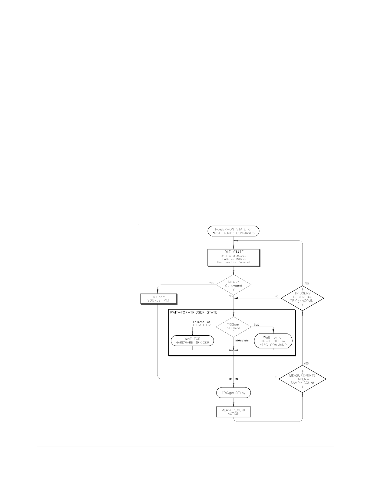
Triggering the Multimeter
This section discusses the multimeter’s trigger system and outlines the
different triggering configurations and programming methods used to
control the trigg er system. Keep i n mind that you do not have to pro gram the
trigger system to make measurements. You can avoid having to learn the
information in this section by using the default trigger configuration set by
MEASure and CONFigure commands. However, you will need the
information in this section to ta ke advantage of the flexibility of the
HP E1312A/E1412A trigger system when using the
The multimeter’s trigger system synchronizes measurements with specified
internal or external events. These events include software trigger commands,
negative-going edges on the VXIbus trigger lines (TTLT0 - TTLT7), and
negative-going pulses on the multimeter's external trigger (“Trig”) BNC
connector. The trigger system also allows you to specify the number of
triggers that will be accepted, the number of readings per trigger (sample
count), and the delay between the trigger and each reading.
Figure 2-1 illustrates the multimeter's trigger system and the programming
commands that control the trigger system. The multimeter operates in one of
two trigger states. When you are configuring the multimeter for
measurements, the multimeter must be in t he idle state. After configuring
the multimeter, the multimeter must be placed in the wait-for-trigger state.
CONFigure command.
Figure 2-1. Multimeter Triggering Flow Chart
HP E1312A/E1412A Multimeter Application Information 45Chapter 2
Page 46

Triggering t he multimeter is a multi-step process that offers triggering
flexibility.
1. You must configure the multimeter for the measurement by selecting
the function, range, resolution, etc.
2. You must specify the source from which the multimeter will accept
the trigger. The multimeter will accept a BUS trigger from the
VXIbus, an external trigger from the front panel “Trig” BNC
connector or an immediate trigger from the multimeter's internal
trigger system.
3. You must make sure that the multimeter is ready to accept a trigger
from the specified trigger source (this is called the wait-for-trigger
state) by issuing a
always uses an immediate t ri gger (s ee t he f lo w char t i n Fi gur e 2- 1 on
page 45).
READ? or INIT command. A MEASure command
The Trigger Source The TRIGger:SOURce <source> command configures the multimeter's
trigger system to respond to the specified source. The following trigger
sources are available:
•BUS: Trigger source is the HP-IB Group Execute Trigger (GET) or
*TRG common command. Within the HP 75000 Series C
the
mainframes, the instrument whose trigger source is “
the last instrument ad dressed to lis ten will respond t o the HP-IB Group
Execute Trigger. The
sent to a specific inst rument not a gr oup of instr uments. NOTE: B-si ze
controllers do not support the BUS trigger (e.g., HP E1306A
command module, HP E1300/E1301A B-size mainframes).
*TRG command differs from GET because it is
BUS” and was
•EXTernal: Trigger source is the mul ti me ter ’s external trigger BNC
connector (labeled “Trig” on the front panel). A falling (negative- going)
edge of the input signal tr igge rs t he mul ti met er. The external pulse
signal must be >1µs, +5V maximum to 0V (TTL levels).
• IMMediate: Internal trigger is always present. If the multimeter is in
the wait-for-trigger state (
sends the trigger. The
automatically set the trigger source to
INITiate), TRIGger:SOURce IMMediate
MEASure and CONFigure commands
IMMediate.
•TTLTrg0 through TTLTrg7: Trigge r source is the VXIbus TTL tr igger
lines. The multimeter is triggered on the falling (negative- going) edge
of a TTL input signal. NOTE: B-size controllers do not support
VXIbus TTL triggers (e.g., HP E1306A Command Module,
HP E1300/E1301A B-Size Mainframes).
For example, the following program statem ent selects the external trigger
BNC connector as the trigger source.
TRIGger:SOURce EXTernal
You can change the trigger source only when the multimeter is in the idle
state. Attempting to change the trigger source while the multimeter is in the
wait-for-trigger state will generate the “Settings conflict” error.
46 HP E1312A/E1412A Multimeter Application Information Chapter 2
Page 47
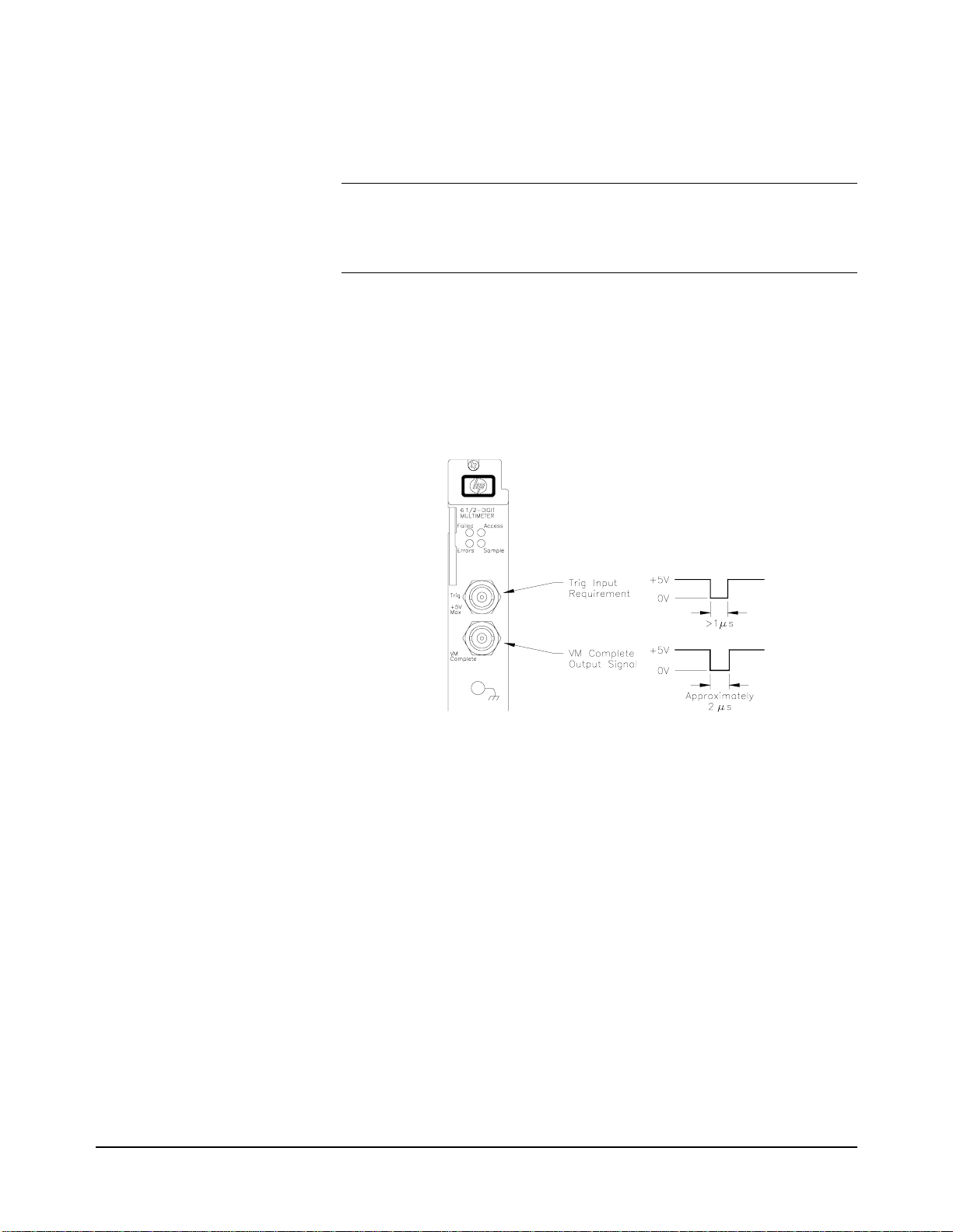
Checking the
Trigger Source
The TRIGger:SOURce? command returns “BUS”, “EXT”, “IMM”, or
“TTLTn” to show the present trigger source. The string is sent to the
output buffer.
Note Note that a CONFigure or MEASure? command automatically sets the
trigger source to
with the
or to TTLTrg<n>. The MEAS? command always uses TRIG:SOUR IMM.
TRIG:SOUR command to set the trigger source to BUS, EXTernal
IMMediate. You must follow the CONFigure command
External Triggering Use TRIGger:SOURce EXTernal to set the trigger source to external.
•The trigger signal must be a low-true pulse with a pulse width greater
than 1µs. The trigger signal level accepted is TTL (+5V maximum
negative-going to 0V). See the following diagram for the “Trig” input
requirement. The diagram also shows the “VM Complete” output you
can use to synchronize with a switch module.
•The multimeter takes one reading (or the number specified by
SAMPle:COUNt) for eac h external trigger received on the front panel
“Trig” BNC connector.
Internal Triggering The trigger signal is always present in the internal triggering mode. This
mode is selected with the
TRIGger:SOURce IMMediate command.
•The multimeter takes one reading (or the number specified by
SAMPle:COUNt) immediately after a READ? or INITiate command.
The multimeter takes only one reading immediately following a
MEAS? command.
•See the triggering process diagram in Figure 2-1 on page 45.
HP E1312A/E1412A Multimeter Application Information 47Chapter 2
Page 48

Bus Triggering The multimeter is triggered from the VXIbus. Thi s mode is selected with the
TRIGger:SOURce BUS command.
•Use the *TRG comman d from the HP-IB to trigger the mul timeter
TRIG:SOUR BUS is used. The *TRG command will not be
when
accepted unless the multimeter is in the wait-for-trigger state.
•You can also trigger the multimeter from the HP-IB interface by
sending the IEEE-488 Group Execute Trigger (GET) message. The
multimeter must be in the wait-for-trigger state. Send a GET from a
Hewlett-Packard controller with the following command:
TRIGGER 70903
Note TRIG:SOUR BUS is not implemented on B-size resource managers, such
as the HP E1306A Command Module or the HP E1300A/E1301A B-size
Mainframes.
The Wait-for-Trigger
State
You must place the multimeter in the wait-for-trigger state after you have
configured it and selected a trigger source. A trigger will not be accepted
until the multime ter is in this stat e. The measureme nt sequence begins when
the multimeter is in the wait-for-trigger state and it receives a trigger.
You can place the multimeter in the “wait-for-trigger” state by executing
one of the following commands:
READ?
INITiate
Note The multimeter requires approximately 20ms of set up time after you send
a command to change to the “wait-for-trigger” state. Any triggers that
occur during this set up time are ignored.
The Trigger Count The TRIG ger:COUNt <number> command sets the number of triggers the
multimeter will accept in the wait-for-trigger sta te before returning to the
idle state. Use the number parameter to set the trigger count to a value
between 1 and 50,000. The
count to 1.
Substituting
Substituting
MIN for the number parameter sets the trigger count to 1.
MAX for the number parameter sets the t rigge r count to 50,0 00.
MEASure and CONFigur e commands set trigge r
48 HP E1312A/E1412A Multimeter Application Information Chapter 2
Page 49

Example: Setting the
Trigger Count
In the following example, one DC voltage measurement is made each time the
multimeter’s external trigger BNC connector is pulsed low. After 10 external
triggers are received, the multimeter returns to the idle state.
Checking the
Trigger Count
Inserting a
Trigger Delay
dimension array
CONF:VOLT:DC
TRIG:SOUR EXT
TRIG:COUN 10
READ?
timeout may occur
enter statement
Dimension computer array.
Function: DC voltage.
Trigger source is external BNC on multimeter front
panel.
Multimeter will accept 10 external triggers (one
measurement is taken per trigger).
Place multimeter in wait-for-trigger state; ma ke
measurements when external trigger is received; send
readings to output buffer.
May require INIT, monitor the status byte for
completion (standard event bit 0), FETC? to transfer
readings to the output buffer (vs. READ?).
Enter readings into computer.
The TRIGger:COUNt? [MINimum|MAXimum] command returns one of the
following numbers to the output buffer:
•The present trigger count (1 through 50, 000) if nei ther MIN nor MAX is
specified.
•The mini mum trigger count available (1) if MIN is specified.
•The maximum trigger count available (50,000) if MAX is specified.
The TRIGger:DELay <seconds> command inserts a delay betw een the
trigger and each measur ement. This includes a dela y between the trigger and
the first measurement and again bef ore each subsequent measurement when
sample count is greater than one. The
delay to a value between 0 and 3600 seconds (with 1µs resolution ).
<seconds> time parameter sets the
Example: Inserting a
Trigger Delay
Substituting
Substituting
MIN for the <seconds> time parameter sets the trigger delay to 0.
MAX for the <seconds> time parameter sets the trigger delay to
3600 seconds.
In the following example, the multimeter will accept 5 triggers from the
external trigger BNC connector. Four measurements are taken per trigger
(sample count is set to 4) and the trigger delay is 2 seconds.
dimension array
CONF:VOLT:DC
TRIG:SOUR EXT
TRIG:COUN 5
SAMP:COUN 4
TRIG:DEL 2
READ?
timeout may occur
enter statement
Dimension computer array.
Function: DC voltag.e
Trigger source is external BNC on multimeter front
panel.
Multimeter will accept 5 external triggers (one
measurement is taken per trigger).
Take 4 measurements for each trigger.
Wait 2 seconds between trigger and start of first
measurement and each subsequent measurement till
sample count reached.
Place multimeter in wait-for-trigger state; ma ke
measurements when external triggers are received;
send readings to output buffer.
May require INIT, monitor the status byte for
completion (standard event bit 0), FETC? to transfer
readings to the output buffer (vs. READ?).
Enter readings into computer.
HP E1312A/E1412A Multimeter Application Information 49Chapter 2
Page 50

Default Delays If you do not specify a trigger delay, the multimeter automatically
determines a delay time (default delay) based on the present measurement
function, range, resolut ion, integration time and AC filter bandwid th setting.
The delay time is actually the settling time required before measurements to
ensure measurement accuracy. The default delay time is automatically
updated whenever you change the function or range. Once you specify a
delay time value, however, the value does not change until you specify
another value, reset the multimeter or do a
table below shows the default trigger delay times for all functions. This
delay will occur before each measurement (see the trigger system diagram
in Figure 2-1 on page 45).
NOTE: You can specify a s horter d elay ti me than the default values shown.
However, the shorter settli ng time may not produce accurate meas urements.
Table 2-7. Default Trigger Delays
Default Trigger Delays for DC Voltage and DC Current (all ranges):
Integration Time Trigger Delay
NPLC ≥11.5ms
NPLC <1 1.0ms
Default Trigger Delays for 2-Wire and 4-Wire Resistance:
CONF or MEAS command. The
Range Trigger Delay
(For NPLC ≥1)
100Ω 1.5ms 1.0ms
1kΩ 1.5ms 1.0ms
10kΩ 1.5ms 1.0ms
100kΩ 1.5ms 1.0ms
1MΩ 1.5ms 10ms
10MΩ 100ms 100ms
100MΩ 100ms 100ms
Default Trigger Delays for AC Voltage and AC Current (all ranges):
AC Filter Trigger Delay
3Hz - 300kHz filter 7.0sec
20Hz - 300kHz filter 1.0sec
200Hz - 300kHz filter 600ms
Default Trigger Delay for Frequency and Period:
Trigger Delay
(For NPLC <1)
1.0s
50 HP E1312A/E1412A Multimeter Application Information Chapter 2
Page 51

Querying the
Delay Time
The TRIGger:DELay? [MINimum|MAXimum] command returns one of the
following numbers to the output buffer:
•The present trigger delay (1
not specified.
µ
s through 3600 seconds) if MIN or MAX is
•The mini mum trigger delay avai lable (1
µ
s) if MIN is specified.
•The maximum trigger delay available (3600 seconds) if MAX is
specified.
The Sample Count The SAMPle:COUNt <number> command designates the number of
readings per trigger. The number parameter sets the number of readings to
a value between 1 and 50,000.
MIN for the number parameter sets the number of readi ngs per
MAX for the number param ete r sets the number of
Dimension computer array.
Function: DC voltage.
Trigger source is external BNC on multimeter front
panel.
Specify 10 readings per trigger.
Place multimeter in wait-for-trigger state; ma ke
measurements when external trigger is received; send
readings to output buffer.
May require INIT, monitor the status byte for
completion (standard event bit 0), FETC? to transfer
readings to the output buffer (vs. READ?).
Enter readings into computer.
Example: Setting the
Sample Count
Substituting
trigger to 1. Substi tuting
readings per trigger to 50,000.
In the following exampl e, 10 DC vol tage measu rements are mad e when th e
multimeter’s external trigger BNC connector is pulsed low. After the
10 readings are taken, the multime ter returns to the idle state.
dimension array
CONF:VOLT:DC
TRIG:SOUR EXT
SAMP:COUN 10
READ?
timeout may occur
enter statement
Checking the
Sample Count
The SAMPle:COUNt? [MINimum|MAXimum] command returns one of the
following numbers to the output buffer:
•The present sample count (1 through 50,000) if neither MIN nor MAX
is specified.
•The minimum sample count available (1) if MIN is specified.
•The maximum sample count available (50,000) if MAX is specified.
HP E1312A/E1412A Multimeter Application Information 51Chapter 2
Page 52

HP E1312A and HP E1412A Multimeter Application Examples
This section contains exampl e programs that demonstrate sever al applications
using the HP E1312A or HP E1412A Multimeter. The examples des cribed in
this section list only t he SCPI commands (see Chapter 3, “Multime ter
Command Reference”) required t o perform the application. The pr ogramming
language is not included in pri nt but C and Visual Basic programs are included
on the VXIplug&play driver medi a under the subdirectory “example s”.
HP VTL Software
(VISA)
Application example programs pr ovided with the HP E1312A or HP E1412A
Multimeter are written usin g VTL 3.0 (VI S A Transi ti on Lan guage). VISA
(Virtual Instrument Softwar e Arc hit ect ure) is an I/O library that can be used
to create instrument driv ers and I /O appl ications. Application programs
written with VTL function call s ca n use VXI plug&play drivers (or SCPI
commands) in systems that have the VTL I/O layer . VTL all ows you t o use
software from different ve ndors together on the same platform. VTL can be
used for I/O application de velo pme nt on Microsoft
supported on the VXI, GPIB-VXI, and GPIB inter faces. VI SA 1.0 pro vide s
more VISA functionality and is full y operational on Windows
Windows NT
®
.
®
Windows 3.1, and is
®
95 and
Example Programs Example programs are provided on the VXIplug&play media. These
programs have been compiled and tested using Microsoft Visual C++
Version 1.51 for the C programs and Microsoft Visual Basic 3.0.
C Programs All projects written in C programming language require the followi ng
settings to work properly.
Project Type: QuickWin application (.EXE)
Project Files: <source code file name>.C
[drive:]\VXIPNP\WIN\LIB\MSC\VISA.LIB (Micro soft compiler)
[drive:]\VXIPNP\WIN\LIB\BC\VISA.LIB (Borland compiler)
Memory Model: Opti ons | Project | Compiler | Memory Model
⇒ Large
Directory Paths: Options | Directories
Include File Paths:
Library File Paths: [drive:]\VXIPNP\WIN\LIB\MSC (Microsoft)
Example Programs:
[drive:]\DSCPI\e1412 (on driver CD)
[drive:]\DSCPI\e1312 (on driver CD)
[drive:]\VXIPNP\WIN\INCLUDE
[drive:]\VXI PNP\WIN \LIB\BC (Borland)
Visual Basic Programs All projects written in the Visual Basic programming language require the
following settings to work properly.
Project Files: <source code file name>.FRM
[drive:]\VXIPNP\WIN\INCLUDE\VISA.BAS
Note If using W indows 3 .1, change “ spc” to “ cps” in t he Memory I/ O Operation s
section of VISA.BAS
52 HP E1312A/E1412A Multimeter Application Information Chapter 2
Page 53

Hardware Used 486 IBM compa tible compute r run nin g Windows 3.1. The c omputer has a n
HP 82341 HP-IB interface and HP SICL/Windows 3.1 and Windows NT
for HP-IB software. The VXI modules were loaded in a VXI C-size
mainframe using an HP E1406A or B-size mainframe with HP E1306A
Command Module as resource manager connected to the computer via the
HP 82341 HP-IB card.
Making Multimeter
Measurements
This section provides four programs that demonstrate different ways of
making measurements and retrieving the readings. SCPI command
sequences for each program are contained in the boxes. The four programs:
1. Use the
2. Make several externally triggered measurements.
3. Maximize measurement speed on multiple measurements.
4. Maximize measurement accuracy on multiple measurements.
NOTE: Review the section titled “Triggering the Multimeter” beginning on
page 45 to fully understa nd the triggering system.
MEASure command to make a single measurement.
MEASure Command The simplest measurement method is using the MEASure command which
configures the function to be measured, initiates the measurement(s) and
places the reading(s) directly into the output buffer. You then must provide
the I/O construct to retrieve the readings and enter them into the computer.
MEASure command will initiate multiple measurements if the tri gger
One
count or the sample count is greater than 1. The measurement process stops
when the output buffer fills if readings are not retrieved fast enough. The
measurement process restarts when there is again room to store readings in the
output buffer.
READ? Command The READ? command requires that you configure the multimeter for the
function you want to measure prior to issuing the command. The command
initiates the measurement(s) and places the reading(s) directly into the output
buffer like the
to retrieve the readings and enter them into the computer. One
command will initiate multiple measurements if the trigger count or the
sample count is greater than 1. The measurement process stops when the
output buffer fills if readings are not retrieved fast enough. The measurement
process restarts when there is room to store readings in the output buffer.
MEASure command. You then must provide the I/O construct
READ?
INIT and FETC?
Commands
The READ? command is broken down into two op erations with the INIT and
FETC? commands. The INIT and FETC? commands require that you
configure the multimeter for the function you want to measure prior to
issuing the commands. T he
places the reading(s ) into the multimeter 's RAM memory. This memory will
hold a maximum of 512 readings. You use the
the readings from memory to the output buffer. You then must provide the
I/O construct to retrieve the readings and enter them into the computer. One
INIT command will initiate multiple measurements if the trigger count or the
sample count is greater than 1. If more than 512 measurements are made,
only the last 512 readings are stored. Use the
than 512 reading s si nce readings are immediatel y put into the out put b uff er
and retrieved with an I/O construct you supply. The measurement process
stops when the output buffer fills if readings are not retrieved fast enough.
HP E1312A/E1412A Multimeter Application Information 53Chapter 2
INIT command initiates the measurem ent(s) and
FETC? command to transfer
READ? command for more
Page 54

The measurement process rest arts when there is again room to stor e readings
in the output buffer.
Measurement Format Readings in the output buffer have the following characteristics:
•Readings sent to the output buffer can consist of two different lengths
(bytes or characters) in Real ASCII format:
±
1.23456E±12
±
1.234567E±12
LF
or
LF
•Each measurement is terminated with a Line Feed (LF). The HP-IB
End-or-Identify (EOI) signal is sent with the last byte transferred. If
multiple measurements are returned, the measurements are separated
by commas and EOI is sent only with the last byte. For example:
±
1.23456E±12
LF
,
±
1.234567E±12
LF
,
±
1.23456E±12
• The multimeter’s internal memory stores 512 readings maximum.
LF EOI
MEASURE1
Source Code File
Comments •The MEASure command configures the multimeter for the function
MEASURE2
Source Code File
Use the MEAS Command to Make a Single Measurement
*RST
MEAS:VOLT:DC?
enter statement
Reset the multimeter.
Configure dc volts (default settings) and measure
retrieve the reading from the multimeter.
Enter reading into computer
specified and initiates the measurement. The reading is stored in the
output buffer and you must provide the I/O construct to retrieve the
reading and enter it into the computer.
Making Externally T riggered Measurements (multiple triggers/samples)
*RST
CONF:VOLT:DC 18
TRIG:SOUR EXT
TRIG:COUN 3
SAMP:COUN 10
INIT
FETC?
enter statement
Reset the multimeter.
Configure for dc volts, expected input = 18V.
Set trigger source to external.
Set trigger count to 3.
Set sample count to 10 per trigge r.
Puts multimeter in wait-for-trigger state. EXTernal
triggers occur here to initiate measurements.
Measurements are stored in multimeter intern al
memory.
Transfer measurements from the multimeter internal
memory to the output buffer and retrieve them with
the computer.
Enter reading into computer.
Comments •You must provide a TTL e xternal trigger signal to the HP E1312A or
HP E1412A front panel “Trig” input BNC. Measurements are triggered
by low pulses of this signal. Each trigger results in 10 readings.
•The CONFigure command configures the multimeter for the function
specified. This
18 (expected input is 18V; the multimeter sets a range to
accommoda te that input which will be 100V). It does not init iate the
measurement.
54 HP E1312A/E1412A Multimeter Application Information Chapter 2
CONFigure command specifies a range parameter of
Page 55

•Trigger source (TRIG:SOUR) is set for an external trigger. A trigger
count (
external triggers.
TRIG:COUN) of 3 is set; the multimeter will accept three
•The sample count (SAMP:COUN) is set for 10 samples per trigger.
•The INITiate command puts the multimeter in the wait-for-trigger state.
The trigger source is an “
trigger and input it on the “Ext Trig” BNC connector which initiates
the measurement process. This will cause the multimeter to make
30 measurements; 10 samples for each of three triggers.
EXTernal” hardware trigger. You provide this
•The FETCh? command causes the readings to be transferred to the
output buffer and you must provide the I/O construct to retrieve the
readings and enter them into the computer.
MEASURE3
Source Code File
Comments •The CONFigure command configures the multimeter for the function
Maximizing Measu remen t Spee d (no t rigge r dela y, short integration time )
*RST
CONF:VOLT:DC 18
CAL:ZERO:AUTO OFF
TRIG:SOUR IMM
TRIG:COUN 3
SAMP:COUN 10
INIT
FETC?
enter statement
specified. This
18 (expected input is 18V; the multimeter sets a range to
accommoda te that input which will be 100V). It does not init iate the
measurement.
CONFigure command specifies a range parameter of
Reset the multimeter.
Configure for dc volts, expected input = 18V.
Turn off autozero (makes faster measurements).
Set the trigger source to immediate.
Set trigger count to 3.
Set sample count to 10.
INITiate command puts multim eter in
wait-for-trigger state; internal trigger immediately
occurs here and measurements are stored in the
multimeter’s internal memory.
Transfer measurements from the multimeter’s
internal memory to the output buffer and retrieve
them with the computer.
Enter reading into computer.
•The autozero function is disabled to speed up the measurement
process. See the
Reference for more information.
CALibrate:ZERO:AUTO command in the Command
•Trigger source (TRIG:SOUR) is set for immediate internal triggers.
A trigger count (
three triggers.
TRIG:COUN) of 3 is set; the multimeter will accept
•The sample count (SAMP:COUN) is set for 10 samples per trigger.
•The INITiate command puts the multimeter in the wait-for-trigger
state. The trigger source is “
trigger source. This trigger occurs immediately and causes the
measurement process t o begin . Thi s wil l caus e the multimet er t o make
30 measurements ; 10 samples for each of three internal triggers.
IMMediate” which specifies the internal
•The FETCh? command causes the readings to be transferred to the
output buffer and you must provide the I/O construct to retrieve the
readings and enter them into the computer.
HP E1312A/E1412A Multimeter Application Information 55Chapter 2
Page 56

MEASURE4
Source Code File
Comments •The CONFigure command configures the multimeter for the function
Maximizing Accuracy (most accurate resolution, longer integration time)
*RST
CONF:VOLT:DC AUTO,MIN
TRIG:SOUR EXT
TRIG:COUN 2
SAMP:COUN 10
READ?
enter statement
specified. This
minimum resolution (the smallest resolution value which is the best
resolution). It does not initiate the measurement.
CONFigure command specifies autorange and
Reset the multimeter.
Configure for dc volts, autorange, minimum
resolution (longest integration time).
Set trigger source to external.
Set trigger count to 2.
Set sample count to 10.
Initiate measurements putting them directly
into output buffer; retrieve them with the
computer.
Enter reading into computer.
•Specifying a small value for resolution provides the most a ccurate
measurements. This will increase the integration time (N PLCs) and
therefore require more time for the measurements.
•Trigger source (TRIG:SOUR) is set for an external trigger. A trigger
count (
external triggers.
TRIG:COUN) of 2 is set; the multimeter will accept two
•The sample count (SAMP:COUN) is set for 10 samples per external
trigger.
•The READ? command puts the multimeter in the wait-for-trigger state.
When the first external trigger is received, the measurement process
begins. This will cause the multimeter to make 10 measurements for
the first external trigger, go to the wait-for-trigger state and take 10
measurements for the second external trigger when received.
•The readings are stored in the output buffer and you must provide the
I/O construct to retrieve the readings and enter them into the computer.
•This example uses the READ? command. Measurements are initiated
with the
trigger state. Measurement occurs when the trigger arrives and readings
are subsequently stored di rect ly in the output buffer and mu st be
retrieved by the computer wit h an I /O construct you supply. An
alternative way of ini ti ati ng m eas urements is to use the
command as done in the previous example. Measurement s are made and
stored in the multimeter’s internal memory and must be retrie ved us ing
the
You must be careful when using the
Internal memory stores a maxi mum of 51 2 readin gs; the old est readin gs
exceeding 512 are lost.
READ? command which puts the multi me ter in the wait-for-
INITiate
FETCh? command which transfers the readings to the outpu t buf fer.
INITiate and FETCh? commands.
56 HP E1312A/E1412A Multimeter Application Information Chapter 2
Page 57

Synchronizing the
Multimeter With a
Switch Module
This program example demonstrates how to synchronize the multimeter
with a switch module. For the HP E1412A it uses the TTL t riggers fr om the
VXI backplane to trigger the multimeter and advance the channel scan list.
The example uses the HP E1476A 64-Channel Multiplexer Module b ut will
also work with any HP sw itch module as long as the ch annel list is specifie d
properly. Figure 2-2 illustrates the C-size set up. The switch module
(multiplexer) and multimeter use the VXI backplane to communicate the
trigger and VM Complete signals to each other to synchronize the scan.
Figure 2-2. HP E1412A Multimeter and Switch Module Synchronization
Figure 2-3 shows the HP E1312A set up using external triggering. B-size
command modules do not support VXIbus TTL triggers.
Figure 2-3. HP E1312A Multimeter and Switch Module Synchronization
HP E1312A/E1412A Multimeter Application Information 57Chapter 2
Page 58
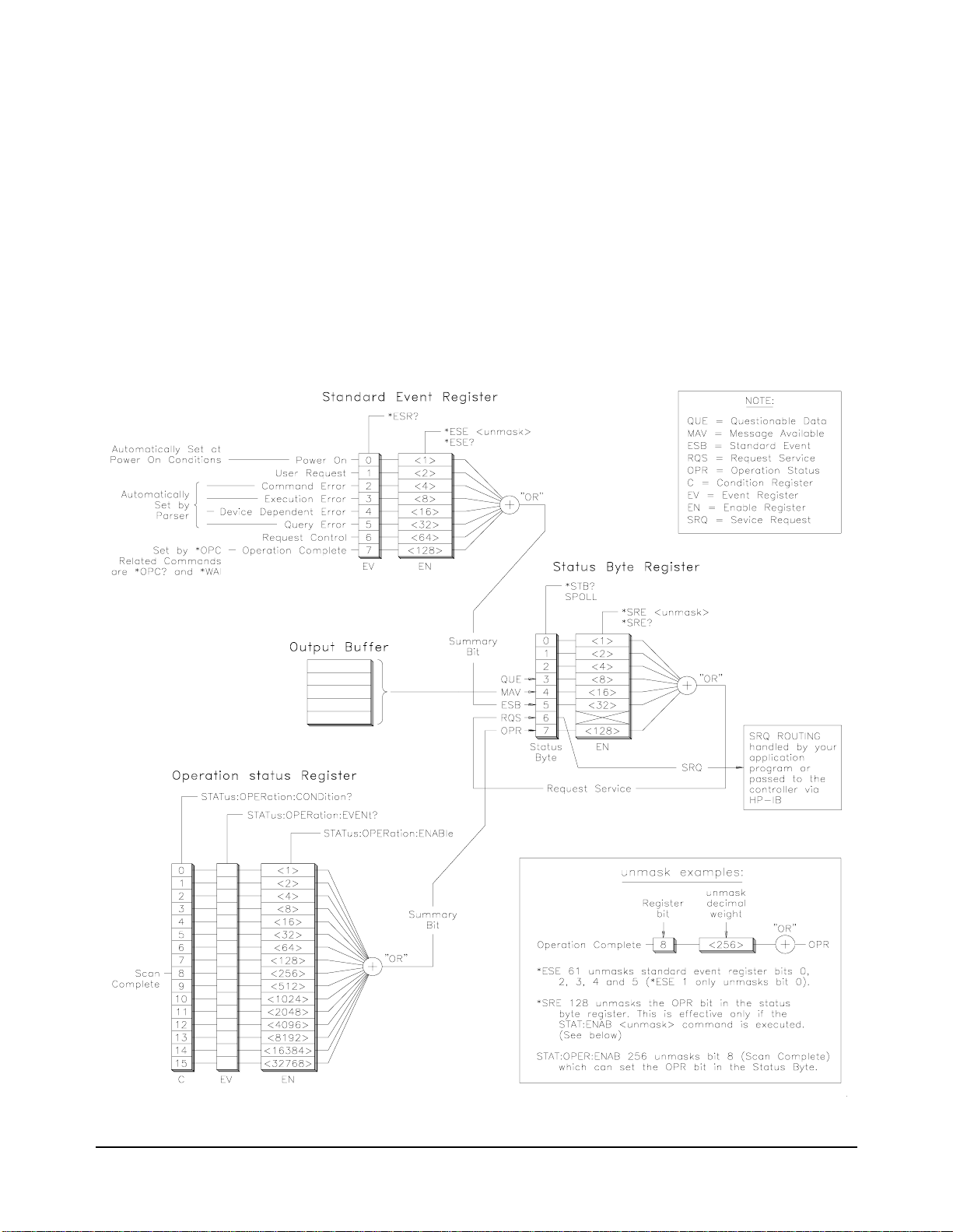
This example monitors the switch module’s status system. The switch
module’s status system (HP E1476A) is shown in Figure 2-4. This example
program enables the swit ch's “Scan Complete ” bit to allow it to set the OPR
bit in the switch's status byte when the scan is finished. The program
repeatedly reads the switch module's status byte until the OPR bit gets set
which returns a status byte value of 128. This indicates the switch module
has completed all closures in the scan list. The multimeter's
FETC?
command causes the multimeter to transfer readings to the output buffer
after completing the last measure ment. Readings are entered into the
computer using an I/O construct you provide.
NOTE: This is the HP E1476A Switch Module’s status system.
See Figure 2-5 for the HP E1312A/E1412A Multimeter status system.
Figure 2-4. HP E1476A Switch Module Status System
58 HP E1312A/E1412A Multimeter Application Information Chapter 2
Page 59

HP E1412 A SCAN
Source Code File
See SCAN1312 Example Program for HP E1312A Code
(The HP E1312A cannot use TTL triggers)
SCPI command sequences for the program are as follows.
**** Set up the Multimeter ****
*RST
*CLS
CONF:VOLT 12,MIN
TRIG:SOUR TTLT2
TRIG:COUN 8
TRIG:DEL 0.01
OUTP:TTLT1:STAT ON
CALC:FUNC AVER
CALC:STAT ON
*OPC?
INIT
**** Now set up the switch module ****
*RST
*CLS
ABOR
STAT:OPER:ENAB 256
OUTP:TTLT2:STAT ON
TRIG:SOUR TTLT1
SCAN (@100:107)
*OPC?
INIT
*****************************************************
Read switch’s status byte until all channels are scanned and scan
complete (bit 8 in the operation status register) sets the OPR bit in the
status byte.
*****************************************************
Retrieve the readings from the multimeter.
FETC?
Retrieve the AVERage math operation response from the
multimeter.
CALC:AVER:AVER?
CALC:AVER:MAX?
CALC:AVER:MIN?
Check the multimeter for system errors.
SYST:ERR?
Reset the multimeter.
Clear the multimeter’s status registers.
Configure for dc volts, 12V input, min res.
Let switch closure trigger multimeter.
Multimeter will accept 8 triggers.
Use a 10 ms delay before each
Output VM Complete to switch via TTLT1.
Select the math function AVERage.
Enable math operations.
Wait until above commands are processed. Read the
response to the *OPC? command from multimeter.
Puts multimeter in the "wait-for-trigger" state;
trigger source is TTLTrig2 line OUTPut by the
switch.
Reset the switch module.
Clear the switch module’s status registers.
Abort any switch operation in progress.
Enable bit 8 of operation status register.
Enable switch closure to trigger multimeter.
Allow VM Complete to advance the scan.
Specify a switch module scan list.
Wait until above commands are processed. Read the
response to the *OPC? command from switch.
Starts scanning by closure of the first channel in the
scan list; sends output signal to multimeter via
TTLTrig2 to trigger a measurement; multimeter
sends TTLT1 (VM Complete) back to switch module
to advance scan to the next channel; measurements
are stored in multimeter internal memory.
Transfer measurements from the multimeter internal
memory to the output buffer and retrieve them with
the computer.
Retrieve the average measurement value.
Retrieve the maximum measurement value.
Retrieve the minimum measurement value.
Retrieve the system error response from the
multimeter.
measurement,
HP E1312A/E1412A Multimeter Application Information 59Chapter 2
Page 60

Multimeter Status
System Examples
There are two program examples t hat demonstrate ho w the HP E1312A and
HP E1412A Multimeter status system works. In both programs the status
byte is repeatedly read to identify when actions by the Multimeter set the
appropriate bit in t he st at us b yte . The co mp ute r ca n id ent if y when rea dings
are available by monitoring the status byte and can retrieve readings when
they are available.
Figure 2-5 illustrates the HP E1312A and HP E1412A status system. A
Questionable Data Register , an Output Buffer and a Standard Event Regi ster
each have a respective status bit in the Status Byte Register. The Output
Buffer sets the MAV bit when there is data available such as measurement
readings or a response to a SCPI query command. The Questionable Data
Register and Standard Even t Reg is ter r equi re you to “ unmask” the bits you
want to be OR'd into a summary bit which sets the respective bit in the Status
Byte. You must also “unmask” the status bits you want OR'd into a summary
bit to set the Service Request bit (SRQ) if you want to generate an interrupt.
The B-size HP E1312A requires you unmask any bit with the
command that you want to read with a SPOLL (the HP E1412A does not
require this unmasking). The example programs illustrate this requirement.
*SRE
Figure 2-5. HP E1312A/E1412A Multimeter Status System
60 HP E1312A/E1412A Multimeter Application Information Chapter 2
Page 61

SYNCHOPC
Source Code File
This program has the multimet er take 10 measurements. The Standa rd Event
bit (ESB) in the status byte (s ee Figure 2-5 on page 60) is monitored to detect
when the operation is complete. Readings are tr ansferred to the outp ut buffer
FETC? command and retrieved by the computer following the
by a
indication that the opera tion has c omplete d. The Mu ltimeter then ca lculate s
the average, minimum and maximum reading.
**** Set up the Multimeter ****
*RST
*CLS
*ESE 1
CONF:VOLT 15
VOLT:DC:NPLC 10
TRIG:COUN 10
TRIG:DEL .01
CALC:FUNC AVER
CALC:STAT ON
*SRE 32
INIT
*OPC
Reset the multimeter.
Clear the multimeter’s status registers.
Enables bit 0 of the multimeter’s standard event
register.
Configure for dc volts, expected input of 15V.
Set number of power line cycles to 10.
Multimeter will accept 10 triggers.
Use a 10ms delay before each
Select the math function AVERage.
Enable math operations.
Required for the E1312A to detect the bit in an
SPOLL.
Puts multimeter in wait-for-trigger state; trig source
is "IMM"; internal trigger occurs "immediately" and
measurements are stored in multimeter internal
memory.
Waits for all measurements to complete then sets bit
0 in the standard event register (the operation
complete bit)
measurement.
Loop
SPOLL - read the multimeter’s status byte until bit 5 (ESB) goes high.
End Loop
FETC?
Transfer measurements from the multimeter internal
memory to the output buffer and retrieve them with
the computer.
Retrieve the AVERage math operation response from the multimeter.
CALC:AVER:AVER?
CALC:AVER:MAX?
CALC:AVER:MIN?
Retrieve the average measurement value.
Retrieve the maximum measurement value
Retrieve the minimum measurement value.
.
Check the multimeter for system errors.
SYST:ERR?
Retrieve the system error response from the
multimeter.
HP E1312A/E1412A Multimeter Application Information 61Chapter 2
Page 62

SYNCHMAV
Source Code File
This program has t he multimeter take 10 measurements just li ke SYNCHOPC.
Readings are transferred to the output buffer by a
FETC? command. The
Message Available bit (MAV) in the status byte (see Figure 2-5 on page 60) is
monitored to detect when the measur ements ar e complet e and the Multi meter
has readings in the output buffer. Readings are retrieved by the computer when
the MAV bit in the status byte indicates the measurements are complete and
readings are available. The Multimeter then calculates the average, minimum
and maximum reading.
**** Set up the Multimeter ****
*RST
*CLS
CONF:VOLT 15
VOLT:DC:NPLC 10
TRIG:COUN 10
TRIG:DEL .01
CALC:FUNC AVER
CALC:STAT ON
*SRE 16
INIT
FETC?
Reset the multimeter.
Clear the multimeter’s status registers.
Configure for dc volts, expected input of 15V.
Set number of power line cycles to 10.
Multimeter will accept 10 triggers.
Use a 10ms delay before each
Select a math function.
Enable the math operations.
Required by the E1312A to detect MAV bit in SPOLL.
Puts multimeter in wait-for-trigger state; trigger
source is "IMM"; internal trigger occurs
"immediately" and measurements are stored in
multimeter internal memory.
Transfer measurements from the multimeter internal
memory to the output buffer and retrieve them with
the computer.
measurement.
Loop
SPOLL - read the multimeter’s status byte until bit 4 (MAV) goes
high to indicate there is a message available in the output buffer.
End Loop
** NOTE: If
measurements complete.
TRIG:COUN is too big, FETC? can timeout before
FETC? expects a response before the timeout
interval specified in the program code. Using the previous program
detecting the OPC bit is recommended.
Retrieve the
CALC:AVER:AVER?
CALC:AVER:MAX?
CALC:AVER:MIN?
AVERage math operation response from the multimeter.
Retrieve the average measurement value.
Retrieve the maximum measurement value.
Retrieve the minimum measurement value.
Check the multimeter for system errors.
SYST:ERR?
Retrieve the system error response from the
multimeter.
62 HP E1312A/E1412A Multimeter Application Information Chapter 2
Page 63

LIMITTST
Source Code File
This program has the multimeter making measu reme nts conti nuously until
an upper or lower limit is exceeded. The lower test limit is set to 2V; the
upper test limit is set to 8V. Questionable Data Register bits 11 and 12 are
unmasked to allow th e LO and HI Limi t Test Failures to set the QUE bit in
the status byte. An input less the 2V or greater than 8V will report a test
failure and halt the program.
**** Set up the Multimeter ****
*RST
*CLS
CONF:VOLT 10
CALC:STAT ON
CALC:LIM:LOW 2
CALC:LIM:UPP 8
CALC:FUNC LIM
STAT:QUES:ENAB 6144
*SRE 8
Reset the multimeter.
Clear the multimeter’s status registers.
Configure for dc volts, 10V range.
Enable the math function.
Set lower limit to 2.
Set upper limit to 8.
Select a math function; set to LIMit.
Unmask the limit error bits.
Required by the E1312A to detect QUE bit in SPOLL.
Loop
READ?
Trigger measurement and place response into the
output buffer.
Enter response into the computer.
SPOLL - read the multimeter’s status byte until bit 3 (QUE) goes
high to indica te there is a Limit Test Failure (HI or LO).
Wait 1 second.
End Loop
Check the multimeter for system errors.
SYST:ERR?
Retrieve the system error response from the
multimeter.
HP E1312A/E1412A Multimeter Application Information 63Chapter 2
Page 64

HP VEE
Programming
Example
HP VEE is HP’s Visual Engineering Environment, a graphical programming
language for creating test systems and solving engineering problems. This
section provides an instrument control example using the “Direct I/O”
feature of HP VEE. Direct I/O allows yo u to direct ly specify messages to b e
sent to an instrument and to directly read the information sent back by an
instrument. Direct I/O also offers the most efficient I/O performance in
HP VEE.
The example provided here sync hronizes a measur ement scan with a swit ch
module. This is the same example previously discussed in this chapter with
programs provided in the C and Visual Basic programming languages.
Device Configuration You must configure your HP E1312A or HP E1412A Multimeter (and the
switch module) before you can communicate with them.
1. Select I/O ⇒ Instrument... from the menu bar. The Instrument
Select or Configure
dialog box pops up.
2. Select the
select
selection pops up the
3. Fill in the
Timeout.
select
pops up.
4. Verify
others).
5. Select
boxes.
6. Select the “name” you put in the name field of the device
configuration dialog box now appearing in the instrument list and
press the
Direct I/O button from the Instrument Type choices. Then
Add Instrument from the Instrument Configure choices. This
Device Configuration dialog box.
Device Configuration Name, Interface, Address and
Set Byte Ordering to MSB and Live Mode to ON. Then
Direct I/O Config... The Direct I/O Configuration dialog box
Conformance is set to IEEE 488 (use default settings for all
OK to close both the Direct I/O and Device Configuration
Get Instr button.
64 HP E1312A/E1412A Multimeter Application Information Chapter 2
Page 65

Program Description The instruments are programmed using Direct I/O objects connected as
required by the sequence of SCPI commands. Reading of the HP E1476A
status byte is perfor med using the
SPOLL whose action is set t o
I/O | Advanced I/O | Device Event object
ANY SET and its mask set to #H80. Thi s mask
allows reading only the OPR bit of the status byte (bit 7) which gets set by
bit 8 (Scan Complete) from the Operation Status Register when the switch
module completes the scan list. Following the detection of scan complete,
the readings are retr ieved with the Multimeter ’s
in an array format to an HP VEE
HP E1412A Measurements. The readings are also sent to a Strip Chart
Display
object which gives a plot of the measurements.
AlphaNumeric Display object titled
FETCh? command and sent
Strip Chart Object In parallel with the HP E1412A Measurements AlphaNumeric Display
object is a
channels. The
the horizontal a nd vertical axis to bes t display the measured data. Upper and
lower boundary traces could be added to the strip chart’s display.
Strip Chart Display object that displays the readings of the eight
Strip Chart has an Auto Scale button to automatically s cal e
HP E1312A/E1412A Multimeter Application Information 65Chapter 2
Page 66

See your HP VEE documentation and on-line help for more detail on test
and measurement I/O contro l. If you ar e not using HP VEE and are curious
about HP’s graphical programming language, call yo ur local HP sal es office
listed in your telephone directory for more information. You can get a free
HP VEE Evaluation Kit containing detailed technical information and a
demo disk that walks you through many of HP VEE’s features and functions.
The following brochures provide additional information about HP VEE:
•HP VEE Visual Engineering Environment
•HP VEE The Most Productive Language for Test and Measurement
•HP VEE Visual Engineering Environment Technical Data
66 HP E1312A/E1412A Multimeter Application Information Chapter 2
Page 67

Multimeter Command Reference
Using This Chapter
This chapter describes the Standard Commands for Programmable Instruments
(SCPI) and IEEE 488.2 Common (*) Commands applicabl e to the HP E1312A and
HP E1412A 6½-Digit Multimeters.
Command Types
Commands are separated into two types: IEEE 488.2 Common Commands and SCPI
Commands.
Chapter 3
Common
Command
Format
SCPI
Command
Format
The IEEE 488.2 standard defines the Common commands that perform functions like
reset, self-test, status byte query, etc. Common commands are four or five characters
in length, always begin with the asterisk character (*), and may include one or more
parameters. The command keyword is separated from the first parameter by a space
character. Some examples of common com mands are shown below:
*RST *ESR 32 *STB?
The SCPI commands perform functions such as making measurements, querying
instrument states, or retrieving data. The SCPI commands are grouped into command
“subsystem structures”. A command subsystem structure is a hierarchical structure
that usually consists of a top level (or root) command, one or more low-level
commands, and their parameters. The following example shows the root command
CALibration
CALibration
and its lower-level subsystem commands:
:COUNt?
:LFRequency 50|60|MIN|MAX
:LFRequency? [MIN|MAX]
:SECure:CODE <
:SECure:STATe OFF|ON, <
:SECure:STATe?
:STRing <
:STRing?
:VALue <
:VALue?
:ZERO:AUTO ON|OFF
:ZERO:AUTO?
quoted string>
value>
new code>
code>
CALibration
STRing, STRing?, VALue and VALue? are second level commands, and CODE,
STATe and STATe? are third level commands.
is the root command, COUNt?, LFRequency, LFRequency?, SECure,
Multimeter Command Reference 67Chapter 3
Page 68

Command
Separator
A colon (:) always separates one command from the next lower level command as
shown below:
CALibration:SECure:STATe?
Colons separate the root command from the second level command
CALibration:SECure) and the second level from the third level (SECure:STATe?).
(
Abbreviated
Commands
Implied
Commands
The command syntax shows most commands as a mixture of upper and lower case
letters. The upper ca se letters i ndicate the abbrevi ated spelling for the command. For
shorter program lines, send the abbreviated form. For bet ter program readability, you
may send the entire command. The instrument will accept either the abbreviated
form or the entire command.
For example, if the command syntax shows
are both acceptable forms. Other forms of
MEASure, then MEAS and MEASURE
MEASure, such as MEASU or MEASUR
will generate an erro r. Additionally, SCPI commands a re case insensitive. The refore,
you may use upper or lower case letters and commands of the form
measure, and MeAsUrE are all acceptable.
MEASURE,
Implied commands are those which appear in square brackets ([]) in the command
syntax. (Note that the brack et s are not part of t he c ommand; do no t se nd the m t o the
instrument.) Suppose you send a second level command but do not send the
preceding implied command. In thi s case, the inst rument as sumes you int end to use
the implied command and it responds as if you had sent it. Examine the partial
[SENSe:] subsystem shown below:
[SENSe:]
FUNCtion “<
FUNCtion?
RESistance
:RANGe <
:RANGe? [MIN|MAX]
function>” (e.g., <function> = VOLT:AC)
range>|MIN|MAX
The root command SENSe is an implied command. For example, to set the multimeter’s
function to AC volts, you can send either of the fol lowing command statements:
SENS:FUNC “VOLT:AC” or FUNC “VOLT:AC”
68 Multimeter Command Reference Chapter 3
Page 69

Parameters Parameter Types. The following table contains explanations and examples of
parameter types you might see later in this chapter.
Parameter Type Explanations and Examples
Numeric Accepts all commonly used decimal repres en tations of number
including optional signs, de cimal points, and scientific notation.
123, 123E2, -123, -1.23E2, .123, 1.23E-2, 1.23000E-01.
Special cases include MINimum, MAXimum, and DEFault.
Boolean Represents a single binary condition that is either true or false.
ON, OFF, 1, 0
Discrete Selects from a finite number of values. These parameters use
mnemonics to represent each valid setting.
An example is the TRIGger:SOU Rce <source> c ommand where
source can be BUS, EXT, or IMM.
Optional Parameters. Parameters shown within square brackets ([]) are optional
parameters. (Note that the brackets are not part of the command; do not send them
to the instrument.) If you do not specify a value for an optional parameter, the
instrument chooses a default value. For example, consider the
TRIGger:COUNt? [MIN|MAX] command. If you send the command without
specifying a
is returned. If you send the
trigger count allowable. If you send the
maximum trigger count allowable. Be sure to place a space between the command
and the parame ter.
MINimum or MAXimum parameter, the present TRIGger:COUNt value
MIN parameter, the command returns the minimum
MAX parameter, the command returns the
Linking
Commands
Linking IEEE 488.2 Common Commands with SCPI Commands. Use only a
semicolon between the commands. For example:
*RST;RES:NPLC 100 or SAMP:COUNt 25;*WAI
Linking Multiple SCPI Commands From the Same Subsystem. Use only a
semicolon between commands within the same subsystem. For example, to set
trigger count, trigger delay and the trigger source whic h are all set using the
TRIGger
subsystem, send the following SCPI string:
TRIG:COUNt 10;DELay .05;SOURce TTLT4
Linking Multiple SCPI Commands of Different Subsystems. Use both a
semicolon and a colon between commands of different subsystems. For example, a
SAMPle and OUTPut command can be sent in the same SCPI string linked with a
semicolon and colon (;:) as follows:
SAMP:COUNt 10;:OUTP:TTLT4 ON
Multimeter Command Reference 69Chapter 3
Page 70

Multimeter Range and Resolution Tables
The following tables list the voltage and resistance ranges available for the
multimeter. Also shown are the associ ated re solut ion val ues vers us ap ertur e time in
seconds or integration time in power line cycles (PLCs) for each range.
Table 3-1. DC Voltage Resolution versus Integration Time or Aperture Time
Integration Time in Power Line Cycles (PLCs)
Aperture Time for 60Hz Line Frequency (seconds)
Maximum
Range
100mV 120mV 30nV 100 nV 300nV 1µV10µV
1V 1.2V 300nV 1µV3µV10µV 100µV
10V 12V 3µV10µV30µV100µV1mV
100V120V30µV100µV 300µV1mV10mV
300V 300V 300µV 1mV 3mV 10mV 100mV
Reading
100 PLCs
1.67s
10 PLCs
167ms
1 PLC
16.7ms
0.2 PLC
3.33ms
0.02 PLC
0.333ms
Table 3-2. DC Current Resolution versus Integration Time or Aperture Time
Integration Time in Power Line Cycles (PLCs)
Aperture Time for 60Hz Line Frequency (seconds)
Maximum
Range
10mA 12mA 3nA 10nA 30nA 100nA 1µA
100mA 120mA 30nA 100 nA 300nA 1µA10µA
1A 1.2A 3nA 1µA3µA10µA 100µA
Reading
100 PLCs
1.67s
10 PLCs
167ms
1 PLC
16.7ms
0.2 PLC
3.33ms
0.02 PLC
0.333ms
3A 3A 900nA 3µA9µA30µA 300µA
70 Multimeter Command Reference Chapter 3
Page 71

Table 3-3. 2-Wire and 4-Wire Resistance Resolution versus Integration Time or Aperture Time
Integration Time in Power Line Cycles (PLCs)
Aperture Time for 60Hz Line Frequency (seconds)
Maximum
Range
100Ω 120Ω 30µΩ 100µΩ 300µΩ 1mΩ 10mΩ
1kΩ 1.2kΩ 300mΩ 1mΩ 3mΩ 10mΩ 100mΩ
10kΩ 12kΩ 3mΩ 10mΩ 30mΩ 100mΩ 1 Ω
100kΩ 120kΩ 30mΩ 100mΩ 300mΩ 1Ω 10Ω
1MΩ 1.2MΩ 300mΩ 1Ω 3Ω 10Ω 100Ω
10MΩ 12MΩ 3Ω 10Ω 30Ω 100Ω 1kΩ
100MΩ 100MΩ 30Ω 100Ω 300Ω 1kΩ 10kΩ
Reading
100 PLCs
1.67s
10 PLCs
167ms
1 PLC
16.7ms
0.2 PLC
3.33ms
0.02 PLC
0.333ms
Table 3-4. AC Voltage: Range versus Resolution
Resolution Choices versus Range
RANGE 100mV 1V 10V 100V 300V
MIN 100nV 1µV10µV 100µV1mV
power-on and
*RST setting
MAX 10µV100µV 1mV 10mV 100 mV
1µV10µV100µV 1mV 10 mV
Table 3-5. AC Current: Range versus Resolution
power-on and
*RST setting
SCPI Command Reference
This section describes the Standard Commands for Programmable Instruments
(SCPI) for the HP E1312A and HP E1412A 6½-Digit Multimeters. Commands are
listed alphabetically by subsystem and also within each subsystem.
Resolution Choices versus Range
RANGE 1A 3A
MIN 1µA3µA
10µA30µA
MAX 100µA300µA
Multimeter Command Reference 71Chapter 3
Page 72

The ABORt command subsystem removes the multimeter from the wait-for-trigger
state and places it in the idle state.
TRIGger:SOURce BUS.
is
Subsystem Syntax ABO R t
Example Aborting a Measurement
ABORt
ABORt is only effective when the trigger source
CONF:VOLT:DC
TRIG:SOUR BUS
INIT
ABOR
Function: DC voltage.
Trigger source is BUS trigger.
Place multimeter in wait-for-trigger state.
Abort waiting for a trigger and place
multimeter in idle state.
Comments • ABORt does not affect any other settings of the trigger system. When the
INITiate command is sent, the trigger system will respond as it did before
ABORt was executed.
• ABORt returns the multimeter to the idle state for TRIGger:SOURce BUS. The
“Trigge r ign ored” error is g enerat ed when a Grou p Execut e Trigger (GET) bus
command or
(which puts the multimeter into the idle state).
*TRG common command is executed after an ABORt command
• Related Commands: INITiate, TRIGger
• *RST Condition: After a a *RST, the mu ltimet er acts a s thoug h an ABORt has
occurred.
72 Multimeter Command Reference Chapter 3
Page 73

CALCulate
There are five math operations available (AVERage, DB, DBM, LIMit, and NULL), only
one can be enabled at a time . Each performs a mathematical operatio n on every reading
or stores data on a series of r eadi ngs. The selected math operation remain s in e ff ect
until you disable it, change functi ons, turn off the power, or perf orm a remote int erface
reset. The math operations use one or more internal registers. You can preset the values
in some of the registers, whil e ot her s hol d the results of the math operation .
The following table shows the math/measurement function combinations allowed.
X” indicates an allowabl e combination. If you choos e a math operation tha t is
Each “
not allowed with the pr esent measur ement funct ion, math is tu rned off. If you select
a valid math operation and then change to one that is invalid, a “Settings conflict”
error is generated over the remote interface. For null and dB measurements, you
must turn on the math operation before writing to their math registers .
Valid Math/Measurement Function Combinations
Measurements
DCV ACV DCI ACI Ω2W Ω4W Freq Per Ratio
AVERage XXXXXXXXX
DB XX DBM XX LIMit XXXXXXXXX
NULL XXXXXXXX
Subsystem Syntax CALCul ate
:AVERage:AVERage?
:AVERage:COUNt?
:AVERage:MAXimum?
:AVERage:MINimum?
:DB:REFerence <
:DB:REFerence? [MIN|MAX]
:DBM:REFerence <
:DBM:REFerence? [MIN|MAX]
:FUNCtion AVERage|DB|DBM|LIMit|NULL
:FUNCtion?
:LIMit:LOWer <
:LIMit:LOWer? [MIN|MAX]
:LIMit:UPPer <
:LIMit:UPPer? [MIN|MAX]
:NULL:OFFSet <
:NULL:OFFSet? [MIN|MAX]
:STATe OFF|ON
:STATe?
value> |MIN|MAX
value> |MIN|MAX
value> |MIN|MAX
value> |MIN|MAX
value> |MIN|MAX
Multimeter Command Reference 73Chapter 3
Page 74

:AV ERa ge :AVERage?
CALCulate:AVERage:AVERage? reads the average of all readings taken since
AVERage was enabled (CALC:FUNC AVER and CALC:STAT ON commands). The
average value is clea red when
the multimeter is reset. The average value is stored in volatile memory.
Example Query the Average of All Readings Taken Since the AVERage Math Operation
was Enabled
AVERage is enabled, when power is removed, or after
CALC:AVER:AVER?
:AVERage:COUNt?
CALCulate:AVERage:COUNt? reads the number of readings taken since
AVERage was enabled (CALC:FUNC AVER and CALC:STAT ON commands). The
count value is cleared when
CALC:STAT ON commands, when power has been off, or after a remote interface
reset. The number of readings taken is stored in volatile memory.
Example Query the Number of Readings Since the AVERage Math Operation was
Enabled
CALC:COUN?
:AVERage:MAXimum?
CALCulate:AVERage:MAXimum? reads the maximum value found from an
AVERage operation. The max value is cleared when AVERage is enabled
CALC:FUNC AVER and CALC:STAT ON commands), when power is removed, or
(
after the multimeter is reset. The maximum value is stored in volatile memory.
Query the average of all readings.
AVERage is enabled by the CALC:FUNC AVER and
Query number of readings.
Example Query the Maximum Value Found During an AVERage Math Operation
CALC:AVER:MAX?
Query the max value.
:AVERage:MINimum?
CALCulate:AVERage:MINimum? reads the minimum value found from an
AVERage function operation. Th e min value is clear ed when AVERage is enabled
CALC:FUNC AVER and CALC:STAT ON commands), when power is removed, or
(
after the multimeter is reset. The minimum value is store d in volatile memory.
Example Query the Minimum Value Found During an AVERage Math Operation
CALC:AVER:MIN?
74 Multimeter Command Reference Chapter 3
Query the min value.
Page 75

:DB:REFerence
Example Set the DB Reference Value
CALCulate:DB:REFerence <value>|MIN|MAX stores a relative value in the dB
Relative Register. You must turn on the math operation e.g., execute
CALC:STAT ON before writing to the math register . You can set the relative valu e
to any number between ±200dBm (the
MIN and MAX values). The dB reference is
stored in volatile memory.
:DB:REFerence?
Example Query the DB Reference Value Set for the DB Math Operation
:DBM:REFerence
CALC:STAT ON
CALC:DB:REF 60
CALC:FUNC DB
CALCulate:DB:REFerence? [MIN|MAX] queries dB reference value.
CALC:DB:REF?
CALCulate:DBM:REFerence <value>|MIN|MAX selects the dBm reference valu e.
Choose from:
900, 1000, 1200, or 8000 ohms. MIN = 50
50, 75, 93, 110 , 124, 125 , 135, 150, 250, 300, 500, 600 (defau lt), 80 0,
Turn on the math operation.
Sets DB reference to 60 dBm.
Select the DB math operation. You can select
the calculate function at any time before or
after enabling the calculate state.
Query the DB reference value.
Ω
. MAX = 8000Ω. You must turn on the
math operation e.g., ex ecute CALC:STAT ON before writing to the math register .
The dBm reference is stored in non-volatile memory.
Example Set the DBM Reference Value
:DBM:REFerence?
CALCulate:DBM:REFerence? [MIN|MAX] queries the dBm reference.
Example Query the DBM Reference Value Set for the DBM Math Operation
CALC:STAT ON
CALC:DBM:REF 135
CALC:FUNC DBM
CALC:DBM:REF?
Turn on the math operation.
Sets DBM reference value to 135.
Select the DBM math operation. You can select
the calculate function at any time before or
after enabling the calculate state.
Query the DBM reference value.
Multimeter Command Reference 75Chapter 3
Page 76

:FUNCtion
CALCulate:FUNCtion AVERage|DB|DBM |LIMit|NULL selects the math function
to be used. One function is enabled at a time with
function MUST be enabled with
CALC:STATe ON.
NULL the default. The selected
Parameter
Summary
• AVERage measurements store the minimum and maximum readings from a
number of measurements. The multimeter records the number of readings
taken since the ave ra ge fun cti on was enabled then ca lc ula te s t he ave rag e of all
the readings. You read these values with
AVERage? and COUNt?.
CALC:AVER:MIN?; MAX?;
• DB measurements are the difference between the input signal and a stored
relative value, with both values converted to dBm.
• DBM operations calculate the power delivered to a resistance referenced to
1 milliwatt.
• The LIMit parameter enables pass/ fail tes ting o n the upper and lowe r limits you
specify using the
LIMit:UPPer and LIMit:LOWer co mmands.
• NULL measurements (also called relative measurements) provide a reading
which is the difference between a stored null value and the input signal.
• See the section titled “Math Ope rati ons” be ginni ng on pa ge 41, for more deta il
on the
Example Set the Calculate Math Function to Make Upper and Lower Limit Tests on
Each Measurement
CALC:FUNC LIM
CALC:LIM:LOWer
CALC:LIM:UPPer
CALC:STATe ON
CALCulate operations.
Set calculate function to limit.
Set the lower limit to test against.
Set the upper limit to test against.
Enable the limit math operation.
:FUNCtion?
CALCulate:FUNCtion? queries the multimeter to determine the present math
function. Returns
Example Query the Calculate Math Function
CALC:FUNC?
76 Multimeter Command Reference Chapter 3
AVER, DB, DBM, LIM, or NULL.
Query the calculate function.
Page 77

:LIMit:LOWer
Example Set the Lower Limit
CALCulate:LIMit:LOWer <value>|MIN|MAX sets the lower limit for limit testing.
You can set the value to any number b etween 0 and ±120% of the highest range , for
the present function.
MIN = –120% of the highest range. MAX = 120% of th e highest
range. You must turn on the math operation e.g., exec ute CALC:STAT ON before
writing to the math register. The lower limit is stored in volatile memory.
:LIMit:LOWer?
Example Query the Lower Limit Set for the LIMit Math Operation
:LIMit:UPPer
CALC:STAT ON
CALC:LIM:LOW 1000
CALC:FUNC LIM
CALCulate:LIMit:LOWer? [MIN|MAX] quer ies the lower limit.
CALC:LIM:LOW?
CALCulate:LIMit:UPPer <value>|MIN|MAX sets the upper limi t for limit testing.
Turn on the math operation.
Set the lower limit.
Select the LIMit math operation. You can select
the calculate function at any time before or
after enabling the calculate state.
Query the lower limit.
You can set the va lue t o any numbe r bet ween 0 an d ±120% of the highest range, f or
the present functi on.
MIN = –120% of the highest range. MAX = 120% of the highest
range. You must turn on the math operation e.g., execute CALC:STAT ON before
writing to the math register. The upper limit is stored in volatile memory.
Example Set the Upper Limit
:LIMit:UPPer?
Example Query the Upper Limit Set for the LIMit Math Operation
CALC:STAT ON
CALC:LIM:UPP 3000
CALC:FUNC LIM
CALCulate:LIMit:UPPer? [MIN|MAX] queries the upper limit.
CALC:LIM:UPP?
Turn on the math operation.
Set the upper limit.
Select the LIMit math operation. You can select
the calculate function at any time before or
after enabling the calculate state.
Queries the upper limit.
Multimeter Command Reference 77Chapter 3
Page 78

:NULL:OFFSet
Example Set the Null Offset Value
CALCulate:NULL:OFFSet <value>|MIN|MAX stores a null value in the
multimeter’s Null Register. You must turn on the math operation e.g., execute
CALC:STAT ON before writing to the math register . You ca n set the nu ll value t o
any number between 0 and ±120% of the highest range, for the present function.
MIN = –120% of the highe st range. MAX = 120% of the highest range. The null value
is stored in volatile memory. See the section titled “Math Operations - NULL
Function” beginning on page 41 for another way to store the offset value.
:NULL:OFFSet?
Example Query the Null Offset Value Set for the NULL Ma th Operation
:STATe
Example Enable the Currently Selected Calculate Math Function
CALC:FUNC NULL
CALC:STAT ON
CALC:NULL:OFFS 500
CALCulate:NULL:OFFSet? [MIN|MAX] queries t he null value.
CALC:NULL:OFFS?
CALCulate:STATe OFF|ON disables or enables the selected math function. The
state is stored in volatile memory.
CALC:STAT ON
Set math function to NULL. You may choose to
set the math function after setting STATe ON.
Turn on math operation.
Set null offset to 500.
Query the null offset value.
The selected or default math function is
enabled.
:STATe?
CALCulate:STATe? queries the st ate of the math function. Returns “0” (OFF) or
1” (ON).
“
Example Query Whether a Math Function State is On or Off
CALC:STAT?
78 Multimeter Command Reference Chapter 3
Query the state.
Page 79

The CALibration command subsystem allows you to enter a security code to prevent
accidental or unauthorized calibrations of the multimeter. When you first receive your
multimeter, it is secured. You must unsecure it by entering the correct security code
before you can calibrate the multimeter (see
Subsystem Syntax CALibration
:COUNt?
:LFRequency 50|60|400
:LFRequency? [MIN|MAX]
:SECure:CODE <
:SECure:STATe OFF|ON,<
:SECure:STATe?
:STRing <
:STRing?
:VALue <
:VALue?
:ZERO:AUTO ON|OFF
:ZERO:AUTO?
:COUNt?
CALibration
CALibration:SECure:STATe command).
new code>
code>
quoted string>
cal_value>
Comments • *RST does not change the calibration count stored in non-volatile memory.
Example Query the Number of Occurrences of Point Calibrations
:LFRequency
Comments • The wrong line frequency setting will cause reading errors to occur.
CALibration:COUNt? queries the multimeter to determine the number of times a
point calibration has occurred. A complete calibration of the multimeter increases
the count by the number of points calibrated. It is not a record of complete
calibrations. The count is stored in non-volatile memory.
CAL:COUN?
CALibration:LFRequency 50|60|400 sets the line frequency to either 50Hz or
60Hz.
Query the calibration count.
• You must execute the CAL:LFR command with a parameter of 50 or 400 to
change the line frequency setting to 50Hz. Specifying 400Hz sets line
frequency to 50Hz since 400 is an even multiple of 50.
• Default Setting: 60Hz
• *RST does not change the line frequency setting.
Example Set the Line Frequency to 50Hz
CAL:LFR 50
Change the line frequency.
Multimeter Command Reference 79Chapter 3
Page 80

:LFRequency?
Comments This command returns +50 for line frequency set to 400 because 400 is an even
Example Query the Line Frequency Setting
CALibration:LFRequency? queries the line frequency setting.
multiple of 50.
:SECure:CODE
Comments • The security code is set to “HP_E141 2” for C-size (or “HP_E1312” for B-size)
CAL:LFR?
CALibration:SECure:CODE <new code> enters a new calibration s ecurity code.
To change the security code, first unsecure the multimeter using the old security code
CAL:SEC:STAT OFF, <old code>. Then, enter the new code. The calibration
with
security code may contain up to 12 characters. The security code is stored in
non-volatile memory.
when the multimeter is sh ipped f rom the f actor y. The security code is stored in
non-volatile memory, and does not change when power has been off or after a
remote interface reset.
Query the line frequency.
• The security code <new code> can contain up to 12 alphanumeric characters.
The first character must be a letter. The remaining characters can be letters or
numbers or an underscor e. You do not have to use all 12 characters but the firs t
character must be a letter.
• If you forget or lose the active security code, you can disable the security
feature by adding a jumper in side the multimeter (see Chapter 5 in the Service
Manual). You then enter a new code and remove the jumper.
Example Enter a New Calibration Security Code
CAL:SEC:STAT OFF, HP_E1412
CAL:SEC:CODE
80 Multimeter Command Reference Chapter 3
the_new_code
Unsecure with the old code.
Enter a new calibration code
(a maximum of 12 characters).
Page 81

:SECure:STATe
Parameters
CALibration:SECure:STATe OFF|ON, <code> unsecures or secures the
multimeter for calibration. The calibration code must be the code set by the
CAL:SEC:CODE command. The state is stored in non-volatile memory.
Parameter Name Parameter Type Range of Values Default Units
OFF|ON boolean OFF | 0 | ON | 1 none
Comments • You can substitute decimal values for the OFF (“0”) and ON (“1”) parameters.
Example Set the Calibration State to Unsecured
:SECure:STATe?
Example Query the Calibration Security State
<code>
discrete up to 12 characters
set by CAL:SEC:CODE
none
• The mu ltimeter calibration is secure d when shipped from the factory. The
security code is set to “
HP_E1412” (or “HP_E1312” for B-size).
• *RST does not change the state.
CAL:SEC:STAT OFF, HP_E1412
CALibration:SECure:STATe? returns a “1” or “0” to show whether the calibration
security state is enabl ed (
CAL:SEC:STAT?
enter statement
1) or disabled (0). The number is se nt t o the outpu t buf fe r.
Unsecure multimeter calibration.
Query multimeter calibration security state.
Enter value into computer.
:STRing
Parameters
Comments •The calibration message can contain up to 40 characters.
CALibration:STRing <quoted string> allows you to record calibration information
about your multimeter while
information such as the l ast calibrati on date and/or the next cal ibration due date. The
calibration message can contain up to 40 characters. Characters in excess of 40 are
truncated and no error is generated. The string is stored in non-volatile memory.
Parameter Name Parameter Type Range of Values Default Units
<quoted string>
CAL:SEC:STAT is OFF. For example, you can store
discrete alphanumeric none
•Calibration security state must be OFF to store a string.
•The calibration message is st ore d i n non-volatile memory and doe s not change
when power has been off or after a remote interface reset.
Multimeter Command Reference 81Chapter 3
Page 82

Example Enter Calibration Information to Record the Next Calibration Date
:STRing?
:VALue
Parameters
CAL:STR ’Cal 4/4/YY, Due 10/4/YY’
CALibration:STRing? queries the calibration message and returns a quoted string
(or a null string “ ” if nothing is present).
Example Query the Calibration Message
CAL:STR?
enter statement
CALibration:VALue <cal_value> specifies the value of the known calibration
signal used by the calibration procedure. See the HP E1312A and HP E1412A
Service Manual, Chapter 5 “Adjustments”, for a more detailed description of the
multimeter's calibration/adjustment procedures.
Parameter Name Parameter Type Range of Values Default Units
cal_value>
<
numeric See the service manual none
Enter a calibration message to record the cal
date of April 4 and next cal due date as
October 4 (YY = year of due date).
Query the calibration message.
Enter value into computer.
Comment • *RST does not affect the calibration value.
:VALue?
Example Enter the Known Value for the Calibration Source Signal
CAL:VAL 10.0
CALibration:VALue? queries the present calibration value.
Enter calibration value.
Example Quer y the Calibrati on Value
CAL:VAL?
enter statement
Query the calibration value.
Enter value into computer.
82 Multimeter Command Reference Chapter 3
Page 83

:ZERO:AUTO
Parameters
Comments • You can use “0” for OFF and “1” for ON in the mode parameter.
CALibrate:ZERO:AUTO <mode> enables or disables the autozero mode. Autozero
applies to dc voltage, dc cur rent and 2-wire ohms measurement s onl y. 4- wir e ohms
and dc voltage ratio measurements automatically enable the autozero mode.
Parameter Name Parameter Type Range of Values Default Units
<mode>
boolean OFF|0|ON|1|ONCE none
• The ON parameter enables autozero. This is the default parameter which
causes the multimeter to internally disconnect the input signal following each
measurement and make a zero measurement. The zero reading is subtracted
from the input signal reading to prevent offset voltages present on the
multimeter’s input circuitry from affecting measurement accuracy.
• The OFF parameter di sables autozero. In this mode the multimeter takes one
zero measurement and subtracts it from all subsequent input signal
measurements prior to a change in function, range or integration time. A new
zero measurement is made foll owing a change i n function , range or inte gration
time. This mode increases measurement speed because a zero measurement is
not made for each input signal measurement.
:ZERO:AUTO?
• Autozero ONCE issues a n immedi ate z ero measu rement and c an be us ed t o get
an update on the zero measurement for a specific input signal measurement.
This helps to increase measurement speed since you update the zero reading
without making zero measurements for every measurement.
• *RST Condition: CALibrate:ZERO:AUTO ON (autozero enabled)
CALibrate:ZERO:AUTO? queries the autozero mode. Ret urns “ 0” (OFF or ONCE)
1” ON.
or “
Multimeter Command Reference 83Chapter 3
Page 84

CALibration?
CALibration? performs a calibration using the specified c alibration value s et by the
CALibrat ion:VA Lue command and queries the calibration response to verify a
successful calibration.
Comments • Execution of this command begins the electronic adjustment for the function
and range the multimeter is set to. The adjustment is performed based on the
value stated in t he
the input terminals.
• The command returns “0” to indicate there are no calibration errors and the
calibration was perf or med. A “
calibration is unable to be performed. The error message is reported to the
output buffer.
• You must set CALibration:SECure:STATe OFF <code> to allow a calibration
to be performed. This requires that you know the calibration secure code. The
secure state enabled prevents unauthorized calibration of the multimeter.
Example Calibrate the Active Function and Range Using the CAL:VALue
CAL:VAL command and the multimeter expects that value at
1” is returned if a cali brati on error occu rs and a
CAL?
monitor the status byte to detect calibration operation complete
enter statement
Perform the calibration.
Enter cal response into computer to verify th e
calibration was successful.
84 Multimeter Command Reference Chapter 3
Page 85

CONFigure
The CONFigure command subsystem configures the multimeter to perform the
specified measurement with the given range and resolution.
make the measurement after setting the configuration. Executing
equivalent to setting the multimeter configuration as follows:
Command Setting
RANGe As specified (or AUTO).
RESolution As specified, or as a function of range, integration
time, or NPLCs.
CONFigure does not
CONFigure is
AC filter
([SENSe:]DET:BAND)
Autozero
([SENSe:]ZERO:AUTO)
Input resistance
([SENSe:]INP:IMP:AUTO)
Samples per trigger
(SAMP:COUN)
Trigger count
(TRIG:COUN)
Trigger delay
(TRIG:DEL)
Trigger source
(TRIG:SOUR)
VM Complete routing
(OUTP:TTLT<
Math function
(CALCulate:STATe)
n>:STAT)
After configuring the multimeter, use the
20 Hz - 300 kHz (medium filter)
OFF if resolution setting results in NPLC <1;
ON if resolution setting results in NPLC ≥1
Applies to dc voltage and is disabled for all other
functions. 10MΩ for all dc voltage ranges.
1 sample
1 trigger
AUTO (Automatic delay)
IMM (trigger signal is always true)
OFF (all trigger lines;
OFF
n = 0 - 7)
INITiate command to place the multimeter
in the wait-for-trigger state and store readings in the multi meter’s internal memory.
Or, use the
READ? command to make the measurement and send the reading s to the
output buffer when the trigger is received.
Subsystem Syntax CONFigure
:CURRent:AC [<range>|MIN|MAX|DEF|AUTO[,<resolution>|MIN|MAX|DEF]]
:CURRent[:DC] [<
:FREQuency [<
:FRESistance [<
:PERiod [<
:RESistance [<
:VOLTage:AC [<
[:VOLTage[:DC]] [<
[:VOLTage[:DC]]:RATio [<
The CONFigure command RANGe and RESolution parameters are optional. You
will get the default range and resolution settings if you do not specify a range or
resolution in the command. You wil l get these default settings even if you set a range
range>|MIN|MAX|DEF|AUTO[,<resolution>|MIN|MAX|DEF]]
range>|MIN|MAX|DEF|AUTO[,<resolution>|MIN|MAX|DEF]]
range>|MIN|MAX|DEF|AUTO[,<resolution>|MIN|MAX|DEF]]
range>|MIN|MAX|DEF|AUTO[,<resolution>|MIN|MAX|DEF]]
range>|MIN|MAX|DEF|AUTO[,<resolution>|MIN|MAX|DEF]]
range>|MIN|MAX|DEF|AUTO[,<resolution>|MIN|MAX|DEF]]
range>|MIN|MAX|DEF|AUTO[,<resolution>|MIN|MAX|DEF]]
range>|MIN|MAX|DEF|AUTO[,<resolution>|MIN|MAX|DEF]]
Multimeter Command Reference 85Chapter 3
Page 86

or resolution different from the default value prior to executing the CONFigure
command. The following table lists the default settings you can expect from the
CONFigure command for each function.
Default Settings for
FUNCTION RANGE RESOLUTION
CURR[:DC] 1A 1µA
CURR:AC 1A 10µA
FREQ FREQ:RANG = 3Hz
FRES 1kΩ 1mΩ
PER PER:RANG = 0.333sec
RES 1kΩ 1mΩ
VOLT[:DC] 10V 10µV
VOLT[:DC]:RAT 10V 10µV
VOLT:AC 10V 100µV
CONFigure Command by Function
30 µHz
VOLT:RANG = 10V
3.33µseconds
VOLT:RANG = 10V
86 Multimeter Command Reference Chapter 3
Page 87

:CURRent:AC
Parameters
CONFigure:CURRent:AC [<range>|MIN|MAX|DEF|AUTO
resolution>|MIN|MAX|DEF]] selects the AC current function and allows you to
[,<
specify the measur ement r ange and resolu tion . See the r ange versus res olu tion table
at the beginning of this chapte r for vali d resoluti on choices for each ac curre nt range.
Parameter Name Parameter Type Range of Values Default Units
range>
<
numeric 1A|3A|
MIN|MAX|DEF|AUTO
A
<resolution>
numeric
resolution|
| MIN | MAX | DEF
A
Comments • To select a standard measurement range, specify range as the input signal’s
maximum expected current. The multimeter then selects the correct range that
will accept the input.
• The AUTO or DEFault option for the range parameter enables autorange.
• The MIN and MAX parameters select the minimum or maximum values for
range and resolution:
For range:
For resolution:
selected range.
MIN = 1A; MAX = 3A
MIN selects the best resolution (the smallest value) for the
MAX selects the worst resolution (the largest value) for the
selected range. See Table 3-5 on page 71 for resolution choices.
• To select autorange, specify DEF for range or do not specify a value for the
range and resolution parameters (see next bullet comment). In the autorange
mode, the multimeter samples the input signal before each measurement and
selects the appropriate range.
• T o specif y the MIN or MAX reso lut i on whil e autoranging, you must specify the
AUTO or DEF parameter for range and specify MIN or MAX e.g.,
CONF:CURR:AC DEF,MIN or CONF:CURR:AC DEF,MAX or
CONF:CURR:AC AUTO,MIN or CONF:CURR:AC AUTO,MAX (you cannot
omit the range parameter
resolution from being interpreted as a range setting.
DEF or AUTO). This prevents the MIN or MAX
Example Making AC Current Measurements
CONF:CURR:AC 3,MAX
SAMP:COUN 3
READ?
enter statement
Function: dc current; range selected: 3A;
MAX resolution: 0.3 mA.
Take 3 readings; trigger source is IMMediate
by default.
Place multimeter in wait-for-trigger state and
make measurements; send readings to output
buffer.
Enter readings into computer.
Multimeter Command Reference 87Chapter 3
Page 88

:CURRent[:DC]
Parameters
CONFigure:CURRent[:DC] [<range>|MIN|MAX|DEF|AUTO
resolution>|MIN|MAX|DEF]] selects the DC current function and allows you to
[,<
specify the measurement range and resolution.
Parameter Name Parameter Type Range of Values Default Units
range>
<
numeric 10mA|100mA|1 A|3 A|
MIN|MAX|DEF|AUTO
A
<resolution>
numeric
resolution|
MIN|MAX|DEF
A
Comments • To select a standard measurement range, specify range as the input signal’s
maximum expected current. The multimeter then selects the correct range to
accept that input.
• The AUTO option for the range parameter enables autorange and will not
accept a resolution parameter but will default the integration time to 10 PLC.
• The DEFault option for the range parameter will also enable autorange.
DEF option for the resolution parameter defaults the integration time to
The
10 PLC.
• The MIN and MAX parameters select the minimum or maximum values for
range and resolution:
For range:
MIN = 10 mA; MAX = 3A
For resolution: See Table 3-1 on page 70 for valid resolution choices for
each range.
• To select autorange, specify AUTO or DEF for range or do not specify a value
for the range and resolution parameters (see next bullet comment). In the
autorange mode, the multimeter samples the input signal before each
measurement and selects the appropriate range.
• To specif y the MIN or MAX resolut i on while autoranging, yo u mu st s p eci f y t he
AUTO or DEF parameter for range and specify MIN or MAX
CONF:CURR:DC DEF,MIN or CONF:CURR:DC DEF,MAX or
e.g.,
CONF:CURR AUTO,MIN or CONF:CURR AUTO,MAX (you cannot omit the
range parameter
from being interpreted as a range setting.
DEF or AUTO). This prevents the MIN or MAX resolution
Example Making DC Current Measurements
CONF:CURR 3,MAX
SAMP:COUN 3
READ?
enter statement
88 Multimeter Command Reference Chapter 3
Function: dc current; range selected: 3A;
MAX resolution: 0.3mA.
Take 3 readings; trigger source is IMMediate
by default.
Place multimeter in wait-for-trigger state and
make measurements; send readings to output
buffer.
Enter readings into computer.
Page 89

:FREQuency
Parameters
CONFigure:FREQuency [<range>|MIN|MAX|DEF|AUTO
resolution>|MIN|MAX|DEF]] selects the frequency function.
[,<
Parameter Name Parameter Type Range of Values Default Units
<range>
numeric 3E+00 Hz
<resolution>
numeric 3E-04 | 3E-05 | 3E-06 Hz
Comments • The frequency function uses one “range” for all inputs between 3Hz and
300kHz. A frequency measurement returns “
0” if no input is applied.
• Range and resolution settings are listed below for the MIN, MAX, DEF and
AUTO parameters and the settings after a module reset (*RST).
PARAMETER RANGE RESOLUTION
MIN 3E+00 3E +06
MAX 3E+00 3E+04
DEF|AUTO
reset (
and module
*RST)
3E+00 3E+05
Multimeter Command Reference 89Chapter 3
Page 90

:FRESistance
Parameters
Comments • To select a standard measurement range, specify range as the input signal’s
CONFigure:FRESistance [<range>|MIN|MAX|DEF|AUTO
resolution>|MIN|MAX| DEF]] sel ect s t he 4- wire ohms function and allows you to
[,<
specify the measurement range a nd resolution.
Parameter Name Parameter Type Range of Values Default Units
range>
<
resolution>
<
numeric 100Ω|1kΩ|10kΩ|100kΩ|1MΩ
|10MΩ|100MΩ|
MIN|MAX|DEF|AUTO
numeric
resolution|MIN|MAX|DEF
ohms
ohms
maximum expected resistance. The multimeter then selects the correct range
that will accept the input.
• The AUTO or DEFault option for the range parameter enables autorange. Th e
DEFault option for resolution defaults the integration time to 10 PLC.
• The MIN and MAX parameters select the minimum or maximum values for
range and resolution:
For range:
MIN = 100
For resolution:
selected range.
Ω
; MAX =100M
MIN selects the best resolution (the smallest value) for the
MAX selects the worst resolution (the largest value) for the
selected range.
• To select autorange, specify DEF for range or do not specify a value for the
range and res olution parameters. In the autorange mode, the multimeter
samples the input signal before each measurement and selects the appropriate
range.
• To specify a MIN or MAX resolution while autoranging, you must
specify the
CONF:FRES DEF,MAX or CONF:FRES AUTO,MIN or
CONF:FRES AUTO,MAX (you cannot omit the range parameter). This
prevents the
AUTO or DEFault parameter; CONF:FRES DEF,MIN or
MIN or MAX resolution from being interpreted as a range setting.
• Related Commands: FETCh?, INITiate, READ?
Example Making 4-Wire Ohms Measurements
CONF:FRES 1500,MAX
SAMP:COUN 3
READ?
enter statement
Ω
Function: 4-wire ohms; range selected: 10kΩ;
MAX resolution: 1Ω.
Take 3 readings; trigger source is IMMediate
by default.
Place multimeter in wait-for-trigger state and
make measurements; send readings to output
buffer.
Enter readings into computer.
90 Multimeter Command Reference Chapter 3
Page 91

:PERiod
Parameters
CONFigure:PERiod [<range>|MIN|MAX|DEF|AUTO
resolution>|MIN|MAX|DEF]] selects the period functi on and allows you to specify
[,<
range and resolution.
Parameter Name Parameter Type Range of Values Default Units
<range>
numeric 3.33E-01 Sec
<resolution>
numeric 3.33E-05| 3.33E-06 | 3.33E-07 Sec
Comments • The period function uses one “range” for all inputs between 0.33 seconds and
3.3µSec. A period measuremen t will return “
0” if no input is applied.
• Range and resolution settings are listed below for the MIN, MAX, DEF and
AUTO parameters and the settings after a module reset (*RST).
PARAMETER RANGE RESOLUTION
MIN 3.33E-01 3.33E-07
MAX 3.33E-01 3.33E-05
DEF|AUTO
reset (
and module
*RST)
3.33E-01 3.33E-06
Multimeter Command Reference 91Chapter 3
Page 92

:RESistance
Parameters
Comments • To select a standard measurement range, specify range as the input signal’s
CONFigure:RESistance [<range>|MIN|MAX|DEF|AUTO
resolution>|MIN|MAX|DEF]] selects the 2-wire ohms functi on and allows yo u to
[,<
specify the range and resolution.
Parameter Name Parameter Type Range of Values Default Units
range>
<
resolution>
<
numeric 100Ω|1kΩ|10kΩ| 100kΩ|1MΩ|
10MΩ|100MΩ|
MIN |MAX| DEF|AUTO
numeric
resolution | MIN |MAX | DEF
ohms
ohms
maximum expected resistance. The multimeter then selects the correct range
that will accept the input.
• The AUTO or DEFault option for the range parameter enables autorange. Th e
DEFault option for resolution defaults the integration time to 10 PLC.
• The MIN and MAX parameters select the minimum or maximum values for
range and resolution:
For range:
MIN = 100
For resolution:
selected range.
Ω
; MAX =100M
MIN selects the best resolution (the smallest value) for the
MAX selects the worst resolution (the largest value) for the
selected range.
• To select autorange, specify DEF for range or do not specify a value for the
range and res olution parameters. In the autorange mode, the multimeter
samples the input signal before each measurement and selects the appropriate
range.
• To specify a MIN or MAX resolution while autoranging, you must specify
AUTO or DEFault for range; CONF:RES DEF,MIN or CONF:RES DEF,MAX
CONF:RES AUTO,MIN or CONF:RES AUTO,MAX (you cannot omit the
or
range parameter). This prevents the
interpreted as a range setting.
• Related Commands: FETCh?, INITiate, READ?
Example Making 2-Wire Ohms Measurements
CONF:RES 850,MAX
SAMP:COUN 3
INIT
FETC?
enter statement
Ω
MIN or MAX resolution from being
Function: 2-wire ohms; range selected: 1kΩ;
MAX resolution: 0.1Ω.
Take 3 readings.
Place multimeter in wait-for-trigger state;
store readings in internal memory; trigger
source is IMMediate by default.
Place readings in outpu t buffer.
Enter readings into computer.
92 Multimeter Command Reference Chapter 3
Page 93

:VOLTage:AC
Parameters
CONFigure:VOLTage:AC [<range>|MIN|MAX|DEF|AUTO
resolution>|MIN|MAX|DEF]] selects the AC-coup led RMS vol tag e f unc ti on and
[,<
allows you to specify the range and resolution.
Parameter Name Parameter Type Range of Values Default Units
range>
<
numeric 0.1V|1V|10V|100V|300V|
MIN|MAX|DEF|AUTO
volts
<resolution>
numeric
resolution|MIN|MAX|DEF
volts
Comments • To select a standard measurement range, specify range as the input signal’s
maximum expected voltage. The multimeter then selects the correct range that
will accept the input.
• The AUTO or DEFault option for the range parameter enables autorange. Th e
DEFault option for resolution defaults the integration time to 10 PLC.
• The MIN and MAX parameters select the minimum or maximum values for
range:
For range:
MIN = 0.1V; MAX = 300V.
For resolution: See Table 3-4 on page 71 for valid resolution choices for
each range.
• To select autorange, specify AUTO or DEF for range or do not specify a value
for the range and resolut ion para meters. In the autoran ge mode, th e multimet er
samples the input signal before each measurement and selects the appropriate
range.
• To specify a MIN or MAX resolution while autoranging, you must specify
AUTO or DEFault for range; CONF:VOLT:AC DEF,MIN or
CONF:VOLT:AC DEF,MAX or CONF:VOLT:AC AUTO,MIN or
CONF:VOLT:AC AUTO,MAX (you cannot omit the range parameter). This
prevents the
MIN or MAX resolution from being interpreted as a range setting.
Example Making AC Voltage Measurements
CONF:VOLT:AC 0.54,MAX
SAMP:COUN 3
READ?
enter statement
Function: AC volts; range selected: 1A;
MAX resolution: 100 µA.
Take 3 readings; source is IMMediate by
default.
Place multimeter in wait-for-trigger state and
make measurements; send readings to output
buffer.
Enter readings into computer.
Multimeter Command Reference 93Chapter 3
Page 94

[:VOLTage[:DC]]
Parameters
CONFigure[:VOLTage[:DC]] [<range>|MIN|MAX|DEF|AUTO
resolution>|MIN|MAX|DEF]] selects the DC voltage function and allows you to
[,<
specify the range and resolution.
Parameter Name Parameter Type Range of Values Default Units
range>
<
numeric 100mV|1V|10V|100V|300V|
MIN|MAX|DEF|AUTO
volts
<resolution>
numeric
resolution|MIN|MAX |DEF
volts
Comments • To select a standard measurement range, specify range as the input signal’s
maximum expected voltage. The multimeter then selects the correct range to
accept the input.
• The AUTO or DEFault option for the range parameter ena bles autorange. Th e
DEFault option for resolution defaults the integration time to 10 PLC.
• The MIN and MAX parameters select the minimum or maximum value for
range and resolution:
For range:
For resolution:
selected range.
MIN = 100mV; MAX = 300V.
MIN selects the best resolution (the smallest value) for the
MAX selects the worst resolution (the largest value) for the
selected range. See Table 3-1 on page 70 for valid resolution choices for
each range.
• To select autorange, specif y DEFault for range or do not s pecify a va lue for t he
range and res olution parameters. In the autorange mode, the multimeter
samples the input signal before each measurement and selects the appropriate
range.
• To specify a MIN or MAX resolution while autoranging, you must specify
AUTO or DEFault for range; CONF:VOLT:DC DEF,MIN or
CONF:VOLT:DC DEF,MAX or CONF:VOLT:DC AUTO,MIN or
CONF:VOLT:DC AUTO,MAX (you cannot omit the range parameter). This
prevents the
MIN or MAX resolution from being interpreted as a range setting.
• Related Commands: FETCh?, INITiate, READ?
Example Making DC Voltage Measurements
CONF:VOLT 0.825,MAX
SAMP:COUN 3
INIT
FETC?
enter statement
94 Multimeter Command Reference Chapter 3
Function: DC voltage; range selected: 1A;
MAX resolution: 100 µA.
Take 3 readings.
Place multimeter in wait-for-trigger state;
store readings in internal memory; trigger
source is IMMediate by default.
Place readings in outpu t buffer.
Enter readings into computer.
Page 95

[:VOLTage[:DC]]:RATio
CONFigure[:VOLTage[:DC]]:RATio [<range>|MIN|MAX|DEF|AUTO
resolution>|MIN|MAX|DEF]] configures the multimeter for dc:dc ratio
[,<
measurements with the specified range and resolution.
DC:DC RATIO =
dc signal voltage
------------------------------------------------ dc reference voltage
Hi and LO input
------------------------------------------------------ -
=
Sense HI and LO input
The ratio is calculated from the voltage applied to the HI and LO input terminals
divided by the reference voltage applied to the “Sense” HI and LO terminals.
Autoranging is automatically selected for the reference voltage measurement on the
“Sense” HI and LO terminals. The specified range in the command applies to the
signal connected to the HI and LO input terminals.
Note Autorange on the “Sense” terminals is from 100mV to 10V range only. Maximum
voltage you can apply to the “Sense” terminals is 10V.
Parameters
Parameter Name Parameter Type Range of Values Default Units
<range>
(HI-LO input)
<
resolution>
numeric 100mV|1V|10V|100V|300V|
MIN|MAX|DEF|AUTO
numeric
resolution|MIN|MAX|DEF
volts
volts
Comments • To select a standard measurement range, specify range as the input signal’s
maximum expected voltage. The multimeter then selects the correct range to
accept the input.
• The AUTO or DEFault option for the range parameter ena bles autorange. Th e
DEFault option for resolution defaults the integration time to 10 PLC.
• The MIN and MAX parameters select the minimum or maximum values for
range and resolution:
For range:
For resolution:
selected range.
selected range.
MIN = 100mV; MAX = 300V.
MIN selects the best resolution (the smallest value) for the
MAX selects the worst resolution (the largest value) for the
Multimeter Command Reference 95Chapter 3
Page 96

CONFigure?
The CONFigure? command queries the multimet er to retu rn the conf iguration set by
the most recent
It returns a quoted string to the output buffer in the following format:
CONFigure or MEASure command.
Subsystem Syntax CONFigure?
Comments • When the multimeter is configured for current, voltage or resistance
measurements,
range and res olution. For example:
• If you sp ecify DEF, MIN, or MAX for the range or resolution parameters in
CONFigure or MEASure, the CONFigure? command returns the selected
value.
• Related Commands: CONFigure, MEASure
Example Querying the Multimeter Configuration
dimension string array
CONF:FRES 900,MAX
CONF?
enter statement
“<function
“CURR:AC +1.000000E+00,1.000000E-05”
“CURR +1.000000E+00,1.000000E-05”
“VOLT:AC +2.000000E+02,1.000000E-06”
“VOLT +3.000000E+02,1.000000E-06”
“FRES +100.0000E+03,1.000000E-05”
“RES +1.000000E+03,1.000000E-03”
“FREQ +3.000000+00,3.000000E-05”
“PER +3.333330E-01,3.333330E-06”
> <
parameter
CONFigure? returns the function follo wed by the selected
>,<
parameter
Dimension computer array to store string.
Function: 4-wire ohms; range selected: 1kΩ;
MAX resolution: 100mΩ.
Query configuration.
Enter string into computer.
>”
String Returned:
“FRES +1.000000E+003,9.999999E-02”
96 Multimeter Command Reference Chapter 3
Page 97

The multimeter can store up to 51 2 readings in internal memory. The DATA
command allows you to determine how many readings are currently stored.
Subsystem Syntax DATA
:POINts?
The INITiate command uses internal memory to store readings prior to a FETCh?
command e.g., when a measurement is initiated by the
query the number of stored readings in memory by sending the
command.
Comments • INITiate command uses internal memory to store readings prior to using a
FETCh? command. You use the DATA:POINts? command to query the
number of readings s tored in internal memo ry to det er mine t h e amount of d ata
space to allocate on your computer to receive the data.
DATA
:POINts?
INITiate command. You can
DATA:POINts?
Multimeter Command Reference 97Chapter 3
Page 98

The FETCh? command retrieves measurements stored in the module’s internal
memory by the most re cent
This command is most commonly used with
Subsystem Syntax FETCh?
Comments Execute INITiate befo re sending th e FETCh? command to place th e multimeter in the
wait-for-trigger state. If the multimeter h as not taken any d ata (i.e., if
not been executed), or if settings have been altered since the last
changing function or range), the “Data corrupt or stale” error will be generated.
Note If you do not alter settings, you could “FETCh?” the sa me da ta over and over again
without error.
• Readings sent to the output buffer can consist of two different lengths
(bytes or characters) in Real ASCII format:
FETCh?
INITiate command and pl aces them in the outpu t buffer.
CONFigure.
INITiate has
FETCh? (i.e.,
±
1.23456E±12
±
1.234567E±12
LF
or
LF
• Each measurement is te rminated with a Line Feed (LF). The HP-IB
End-or-Identify (EOI) signal is sent with the last byte transferred. If multiple
measurements are returned, the measurements are separated by commas and
EOI is sent only with the last byte. For example:
±
1.23456E±12
LF
,
±
1.234567E±12
LF
,
±
1.23456E±12
• The Multimeter’s internal memory stores 512 readings maximum.
• Related Commands: CONFigure, INITiate, READ?
• *RST Condition: Executing FETCh? after a *RST generates error “Data
corrupt or stale” (
Example Transferring Stored Readings to Output Buffer
dimension array
CONF:VOLT:DC
SAMP:COUN 100
INIT
FETC?
enter statement
*RST places the multimeter in the idle state).
Dimension computer array to store
100 readings.
Function: DC voltage.
100 readings per trigger.
Store readings in internal memory; trigger
source is IMMediate by default.
Place readings in outpu t buffer.
Enter readings into computer.
LF EOI
98 Multimeter Command Reference Chapter 3
Page 99

The INITiate command subsystem places the multimeter in the wait-for-trigger state.
This command is most commonly used with
“Triggering the Mult imeter” beg inning on page 45 for a complete description of the
HP E1312A and HP E1412 trigger system which discusses th e wait-for-tr igger stat e.
Subsystem Syntax INITiate
[:IMMediate]
[:IMMediate]
INITiate[:IMMediate] places the multimeter in the wait-for-trigger state. When a
trigger is received, readings are placed in multimeter internal memory.
Comments • After the trigger system is initiated u sing INITiate, use the TRIGger command
subsystem to control the be havior of the tri gger system.
• If TRIGger:SOURce is IMMediate, the measurement starts and readings are
stored in internal memory as soon as
memory from previous commands are replaced by the new readings.
INITiate
CONFigure. See the section titled
INITiate is execu ted. Readings stored in
• To transfer readings from memory to the output buffer, use the FETCh?
command.
• If TRIGger:SOURce is not IMMediate , the measurement starts as soon as a
trigger is received either from the external BNC connector, the VXIbus
backplane (
TTLT<n> trigger lines) or a BUS trigger.
• The READ? command executes INITiate implicitly. The MEASure command
executes
output buffer, bypassing the multimeter’s internal memory.
READ? implicitly. Executing READ? outputs data directly to the
• Related Commands: CONFigure, FETCh?, READ?
• *RST Condition: *RST places the multimeter in the idle state.
Example Placing Multimeter in Wait-For-Trigger State
CONF:VOLT:DC
TRIG:SOUR EXT
INIT
FETC?
INIT
Function: DC voltage.
Trigger source is the external BNC on the
multimeter.
Place multimeter in wait-for-trigger state;
store readings in internal memory when ext
trigger is received.
Place readings in outpu t buffer.
You must re-initiate the wait-for-trigger state
after each trigger cycle.
Multimeter Command Reference 99Chapter 3
Page 100

The INPut command enables or disables the automatic i nput impedance mode for DC
voltage measurements.
Subsystem Syntax INPut
:IMPedance:AUTO
INPut:IMPedance:AUTO <mode> enables or disables the automatic input
impedance mode for DC voltage measurements. When disabled (
multimeter maintains its input impedance of 10MΩ for all DC voltage ran g es . Thi s
is useful to prevent a change in input impedance, caused by changing ranges, from
affecting the measurements.
Parameters
Parameter Name Parameter Type Range of Values Default Units
:IMPedance:AUTO OFF|ON
:IMPedance:AUTO?
<mode>
boolean OFF|0|ON|1 None
INPut
AUTO OFF), the
Example Enable Automatic Input Impedance (use >10G
Comments • You can substitute decimal values for the OFF (“0”) and ON (“1”) parameters.
:IMPedance:AUTO?
INPut:IMPedance:AUTO? returns a number to show whether the automatic input
impedance mode is enabl ed or di sabled: “
to the output buffer.
Example Query the Input Impedance Mode
mode (Impedance)
Range for
Impedance
INP:IMP:AUTO ON
AUTO OFF
(10 M Ω)
all ranges 100mV, 1V and 10V
Enable automatic input impedance.
• *RST Conditions: INP:IMP:AUTO OFF
1” = ON, “0” = OFF. The number is sent
INP:IMP:AUTO ON
INP:IMP:AUTO?
enter statement
Enable automatic input impedance.
Query multimeter to return input impedance
mode (“1”).
Enter value into computer.
AUTO ON (>10GΩ)
(other ranges are at 10MΩ)
Ω
for 100mV, 1V and 10V ranges)
100 Multimeter Command Reference Chapter 3
 Loading...