

Page 1

HP Pavilion dv6 Entertainment PC
Maintenance and Service Guide
Page 2

© Copyright 2009 Hewlett-Packard
Development Company, L.P.
AMD Athlon, ATI Mobility Radeon, AMD
Sempron, and AMD Turion are trademarks of
Advanced Micro Devices, Inc. Bluetooth is a
trademark owned by its proprietor and used
by Hewlett-Packard Company under license.
Intel is a registered trademark of
Intel Corporation in the U.S. and
other countries. Microsoft, Windows, and
Windows Vista are U.S. registered
trademarks of Microsoft Corporation.
SD Logo is a trademark of its proprietor.
The information contained herein is subject
to change without notice. The only
warranties for HP products and services are
set forth in the express warranty statements
accompanying such products and services.
Nothing herein should be construed as
constituting an additional warranty. HP shall
not be liable for technical or editorial errors
or omissions contained herein.
Second Edition: May 2009
First Edition: March 2009
Document Part Number: 532395-002
Page 3

Safety warning notice
WARNING! To reduce the possibility of heat-related injuries or of overheating the computer, do not
place the computer directly on your lap or obstruct the computer air vents. Use the computer only on a
hard, flat surface. Do not allow another hard surface, such as an adjoining optional printer, or a soft
surface, such as pillows or rugs or clothing, to block airflow. Also, do not allow the AC adapter to contact
the skin or a soft surface, such as pillows or rugs or clothing, during operation. The computer and the
AC adapter comply with the user-accessible surface temperature limits defined by the International
Standard for Safety of Information Technology Equipment (IEC 60950).
iii
Page 4

iv Safety warning notice
Page 5

Table of contents
1 Product description
2 External component identification
Top components ................................................................................................................................... 6
TouchPad ............................................................................................................................ 6
Lights ................................................................................................................................... 7
Buttons, speakers and fingerprint reader ............................................................................. 9
Keys ................................................................................................................................... 11
Front components .............................................................................................................................. 12
Rear component ................................................................................................................................. 13
Right-side components ....................................................................................................................... 13
Left-side components ......................................................................................................................... 14
Bottom components ........................................................................................................................... 15
Display components ........................................................................................................................... 16
Cleaning the display .......................................................................................................... 16
Wireless antennas (select models only) ............................................................................................. 17
3 Illustrated parts catalog
Service tag ......................................................................................................................................... 18
Computer major components ............................................................................................................. 19
Display assembly components ........................................................................................................... 26
AntiGlare display assembly spare parts ............................................................................ 26
BrightView display assembly spare parts .......................................................................... 27
Plastics Kit .......................................................................................................................................... 28
Cable Kit ............................................................................................................................................. 29
Miscellaneous parts ............................................................................................................................ 30
Sequential part number listing ............................................................................................................ 31
4 Removal and replacement procedures
Preliminary replacement requirements ............................................................................................... 41
Tools required .................................................................................................................... 41
Service considerations ....................................................................................................... 41
Plastic parts ....................................................................................................... 41
v
Page 6

Cables and connectors ..................................................................................... 42
Drive handling ................................................................................................... 42
Grounding guidelines ......................................................................................................... 43
Electrostatic discharge damage ........................................................................ 43
Packaging and transporting guidelines ............................................. 44
Workstation guidelines ..................................................................... 44
Equipment guidelines ....................................................................... 45
Component replacement procedures ................................................................................................. 46
Service tag ......................................................................................................................... 46
Computer feet .................................................................................................................... 47
Battery ............................................................................................................................... 48
Webcam/microphone module ............................................................................................ 49
Optical drive ....................................................................................................................... 51
Memory module ................................................................................................................. 53
TV tuner module ................................................................................................................ 55
RTC battery ....................................................................................................................... 56
Hard drive .......................................................................................................................... 57
WLAN module .................................................................................................................... 60
Switch cover and keyboard ................................................................................................ 63
Power button board ........................................................................................................... 67
Display assembly ............................................................................................................... 68
Speaker ............................................................................................................................. 78
Bluetooth module ............................................................................................................... 79
Top cover ........................................................................................................................... 80
Modem module .................................................................................................................. 83
Audio/infrared board .......................................................................................................... 84
USB board ......................................................................................................................... 85
Power connector cable ...................................................................................................... 86
System board ..................................................................................................................... 88
TV tuner module cable ....................................................................................................... 90
Modem module cable ........................................................................................................ 91
Fan/heat sink assembly ..................................................................................................... 92
Processor ........................................................................................................................... 96
5 Setup Utility
Starting the Setup Utility ..................................................................................................................... 98
Using the Setup Utility ........................................................................................................................ 99
Setup Utility menus .......................................................................................................................... 101
vi
Changing the language of the Setup Utility ....................................................................... 99
Navigating and selecting in the Setup Utility ...................................................................... 99
Displaying system information ......................................................................................... 100
Restoring default settings in the Setup Utility .................................................................. 100
Exiting the Setup Utility .................................................................................................... 100
Page 7

6 Specifications
Computer specifications ................................................................................................................... 103
15.6-inch, WXGA display specifications ........................................................................................... 104
16.0-inch WXGA BrightView display specifications .......................................................................... 105
16.0-inch WXGA AntiGlare display specifications ............................................................................ 106
Hard drive specifications .................................................................................................................. 107
Blu-ray ROM DVD±R/RW SuperMulti Double-Layer Drive specifications ........................................ 108
DVD±RW SuperMulti Double-Layer Combo Drive specifications .................................................... 109
System DMA specifications .............................................................................................................. 110
System interrupt specifications ......................................................................................................... 111
System I/O address specifications ................................................................................................... 112
System memory map specifications ................................................................................................. 114
7 Screw listing
Phillips PM2.0×3.0 screw ................................................................................................................. 116
Phillips PM2.0×14.0 captive screw ................................................................................................... 119
Phillips PM2.5×3.0 screw ................................................................................................................. 121
Phillips PM2.5×4.0 screw ................................................................................................................. 122
Phillips PM2.5×6.0 screw ................................................................................................................. 124
Phillips PM2.0×2.0 broadhead screw ............................................................................................... 125
Phillips PM2.5×5.0 screw ................................................................................................................. 126
Phillips PM2.5×5.0 captive screw ..................................................................................................... 128
Phillips PM2.5×5.5 captive screw ..................................................................................................... 130
Phillips PM2.5×7.0 screw ................................................................................................................. 131
Phillips PM3.0×3.5 screw ................................................................................................................. 134
Main menu ....................................................................................................................... 101
Security menu .................................................................................................................. 101
System Configuration menu ............................................................................................ 101
Diagnostics menu ............................................................................................................ 102
8 Backup and Recovery
Recovering system information ........................................................................................................ 135
Creating recovery discs ................................................................................................... 136
Backing up your information ............................................................................................................. 137
When to back up .............................................................................................................. 137
Backup suggestions ......................................................................................................... 137
Using system restore points ............................................................................................ 137
Performing a recovery ...................................................................................................................... 139
Recovering from the recovery discs ................................................................................ 139
When to create restore points ......................................................................... 137
Create a system restore point ......................................................................... 138
Restore to a previous date and time ............................................................... 138
vii
Page 8

Recovering from the dedicated recovery partition (select models only) .......................... 139
9 Connector pin assignments
1394 ................................................................................................................................................. 140
Audio-in (microphone) ...................................................................................................................... 140
Audio-out (headphone) ..................................................................................................................... 141
External monitor ............................................................................................................................... 141
HDMI ................................................................................................................................................ 142
RJ-11 (modem) ................................................................................................................................ 143
RJ-45 (network) ................................................................................................................................ 143
Universal Serial Bus ......................................................................................................................... 144
10 Power cord set requirements
Requirements for all countries or regions ......................................................................................... 145
Requirements for specific countries or regions ................................................................................ 146
11 Recycling
Battery .............................................................................................................................................. 147
Display .............................................................................................................................................. 147
Index ................................................................................................................................................................. 153
viii
Page 9

1 Product description
Category Description Computers
with discrete
graphics
Product Name HP Pavilion dv6 Entertainment PC √ √
Processors AMD Turion™ ZM-87, 2.4-GHz with 2-MB L2 cache √ √
AMD Turion ZM-86, 2.4-GHz with 2-MB L2 cache √ √
AMD Turion ZM-85, 2.3-GHz with 2-MB L2 cache √ √
AMD Turion ZM-84, 2.3-GHz with 2-MB L2 cache √ √
AMD Turion ZM-82, 2.2-GHz with 2-MB L2 cache √ √
AMD Turion RM-77, 2.3-GHz with 2-MB L2 cache √ √
AMD Turion RM-75, 2.2-GHz with 2-MB L2 cache √ √
AMD Turion RM-74, 2.2-GHz with 2-MB L2 cache √ √
AMD Athlon™ QL-67, 2.2-GHz with 1-MB L2 cache √ √
AMD Athlon QL-65, 2.1-GHz with 1-MB L2 cache √ √
AMD Athlon QL-64, 2.1-GHz with 1-MB L2 cache √ √
AMD Sempron™ SI-42, 2.1-GHz with 512-KB L2 cache √ √
Chipset Northbridge: AMD M780G Chipset √
Computers
UMA
graphics
Northbridge: AMD M770 Chipset √
Southbridge: SB700 √ √
Graphics ATI Mobility Radeon™ HD 4650 (M96) with 1 GB of dedicated
video memory (64 MB × 16 DDR3 × 8 PCs)
ATI Mobility Radeon HD 4530 (M92) with 512 MB of dedicated
video memory (64 MB × 16 DDR3 × 4 PCs)
AMD internal graphics with 64-MB SidePort video memory (32
MB × 16)
Unified memory architecture (UMA) with shared video memory
(ATI Radeon HD 3200 graphics):
Up to 251 MB for = 1024-MB system RAM
●
Up to 358 MB for > 2048-MB system RAM
●
Memory size is dynamic change
●
√
√
√
√
1
Page 10

Category Description Computers
with discrete
graphics
Support for BD playback with HD Decode, and DX10 √ √
Computers
UMA
graphics
Panels
Memory 2 SODIMM slots √ √
Customer-accessible/upgradable √ √
PC2-6400, 800-MHz, DDR2 √ √
Dual-channel support √ √
Supports up to 8-GB system memory
15.6-inch WXGA (1366 × 768) BrightView LED
●
15.6-inch WXGA (1366 × 768) AntiGlare LED
●
16.0-inch WXGA (1366 × 768) BrightView LED
●
16.0-inch WXGA (1366 × 768) AntiGlare LED
●
15.6-inch cold cathode fluorescent lamps (CCFL) panel
●
16.0-inch CCFL panel
●
AntiGlare glass panel cover support
●
Support for lighted logo on display enclosure
●
Typical brightness 160 nits
●
1024-MB total system memory (1024 MB × 1, dual-
●
channel)
2048-MB total system memory (1024 MB × 2, dual-
●
channel)
√ √
√ √
√ √
√ √
√ √
√ √
√ √
√ √
√ √
√ √
2048-MB total system memory (2048 MB × 1, dual-
●
channel)
3072-MB total system memory (2048 MB + 1024 MB)
●
4096-MB total system memory (2048 MB × 2, dual-
●
channel)
6144-MB total system memory (2048 MB + 4096 MB)
●
8192-MB total system memory (4096 MB × 2, dual-
●
channel)
Hard drives Supports all Serial ATA (SATA) 9.5-mm, 6.35-cm (2.50-in)
hard drives
Supports one hard drive √ √
Support for HP ProtectSmart Hard Drive Protection √√
√ √
2 Chapter 1 Product description
Page 11

Category Description Computers
with discrete
graphics
Computers
UMA
graphics
Single hard drive configurations:
160 GB (5400 rpm)
●
250 GB (7200 rpm) (select models only)
●
250 GB (5400 rpm)
●
320 GB (7200 rpm) (select models only)
●
320 GB (5400 rpm)
●
500 GB (5400 rpm)
●
Optical drives 12.7-mm tray load √ √
Serial ATA (SATA) √ √
Fixed (removal of one screw required) √ √
Supports the following optical drives:
DVD±RW and CD-RW SuperMulti Double-Layer Combo
●
Drive
Blu-ray ROM with LightScribe DVD±R/RW SuperMulti
●
Double-Layer Drive
Webcam Standard VGA camera √ √
Fixed (no tilt) √ √
√ √
√ √
Activity LED √ √
640 × 480 by 24 frames per second √ √
Microphone 2 omnidirectional digital microphones, dual-array with
appropriate software (supports beam forming, echo
cancellation, and noise suppression)
Audio HD Audio √ √
Supports Microsoft® Premium Requirements √ √
Pavilion-branded Altec Lansing speakers √ √
Modem 56K V.92 data/fax modem (select models only) √ √
Supports all worldwide certification requirements √ √
Ethernet Integrated Realtek 10/100/1000 network interface card (NIC) √
Integrated Realtek 10/100 NIC √
Wireless Integrated wireless local area network (WLAN) options by way of wireless module:
Broadcom BCM4312 802.11b/g + Bluetooth with two antennas √ √
Atheros 9280AGN 802.11a/b/g/n + Bluetooth √ √
Broadcom BCM4312 802.11b/g + Bluetooth √ √
Atheros 9285G 802.11b/g + Bluetooth® with two antennas √ √
√ √
TV tuner Integrated DVB-T TV tuner (select models only) √√
3
Page 12

Category Description Computers
with discrete
graphics
Computers
UMA
graphics
Support for TV tuner antennas for both DVB-T and ATSC/
NTSC
External media card One ExpressCard 54 slot √ √
Digital Media Slot, supports SD, MMC, MS, MSP, xD. Supports
Internal card expansion Two Mini Card slots
Ports VGA, 15-pin supporting 1920 × 1200 resolution at 75Hz √
VGA, 15-pin supporting 1600 × 1200 resolution at 75Hz √
Hot Plug/Unplug and auto-detect for correct output to wide-
High-Definition Multimedia Interface (HDMI) v1.3b supporting
eSATA port combo with fourth USB port √ √
Four USB 2.0 ports √ √
IEEE 1394a √
mini versions of SD, MMC, MS Duo with adapter (adapter is
not included)
One slot for WLAN
●
One slot for TV tuner
●
aspect vs. standard-aspect video
1080p with HDCP key
√
√ √
√ √
√ √
√ √
RJ-11 modem (select models only) √ √
RJ-45 Ethernet √ √
Consumer infrared √ √
MCX connector for TV antennas (select models only) √ √
Two stereo headphone jacks (audio-out) √ √
Microphone input (audio-in) √ √
AC adapter plug √ √
Docking Expansion port 3 supports the HP Notebook Expansion Base
and HP Notebook QuickDock
Keyboard/pointing devices 16-inch full-size keyboard with numeric keypad √ √
Standard IMR keyboard √ √
UV painted keyboard (select models only) √ √
Textured (non-painted) keyboard (select models only) √ √
TouchPad supports 2-way scrolling √ √
Taps enabled as default √ √
Power requirements 6-cell 2.55-Ah Li-ion battery with target life of 2.5 hours √
6-cell 2.55-Ah Li-ion battery with target life of 3 hours √
√ √
6-cell 2.20-Ah Li-ion battery with target life of 2.2 hours √
4 Chapter 1 Product description
Page 13

Category Description Computers
with discrete
graphics
6-cell 2.20-Ah Li-ion battery with target life of 2.25 hours √
12-cell 8.80-Ah Li-ion battery with target life of 4 hours √
12-cell 8.80-Ah Li-ion battery with target life of 5 hours √
90-W AC adapter √
65-W AC adapter √
Security Security cable slot √ √
Fingerprint reader (select models only) √ √
Operating system Preinstalled:
Computers
UMA
graphics
Windows Vista Home Basic (32-bit) Service Pack 2 √ √
Windows Vista Premium (32-bit and-64 bit) Service Pack 2 √ √
Windows Vista Ultimate (64-bit) Service Pack 2 √ √
Serviceability AC adapter √ √
Battery (system) √ √
Hard drive √ √
Memory module √ √
Optical drive √ √
Mini Card components √√
Windows Vista® Business (32-bit) Service Pack 2 √ √
5
Page 14
2 External component identification
Top components
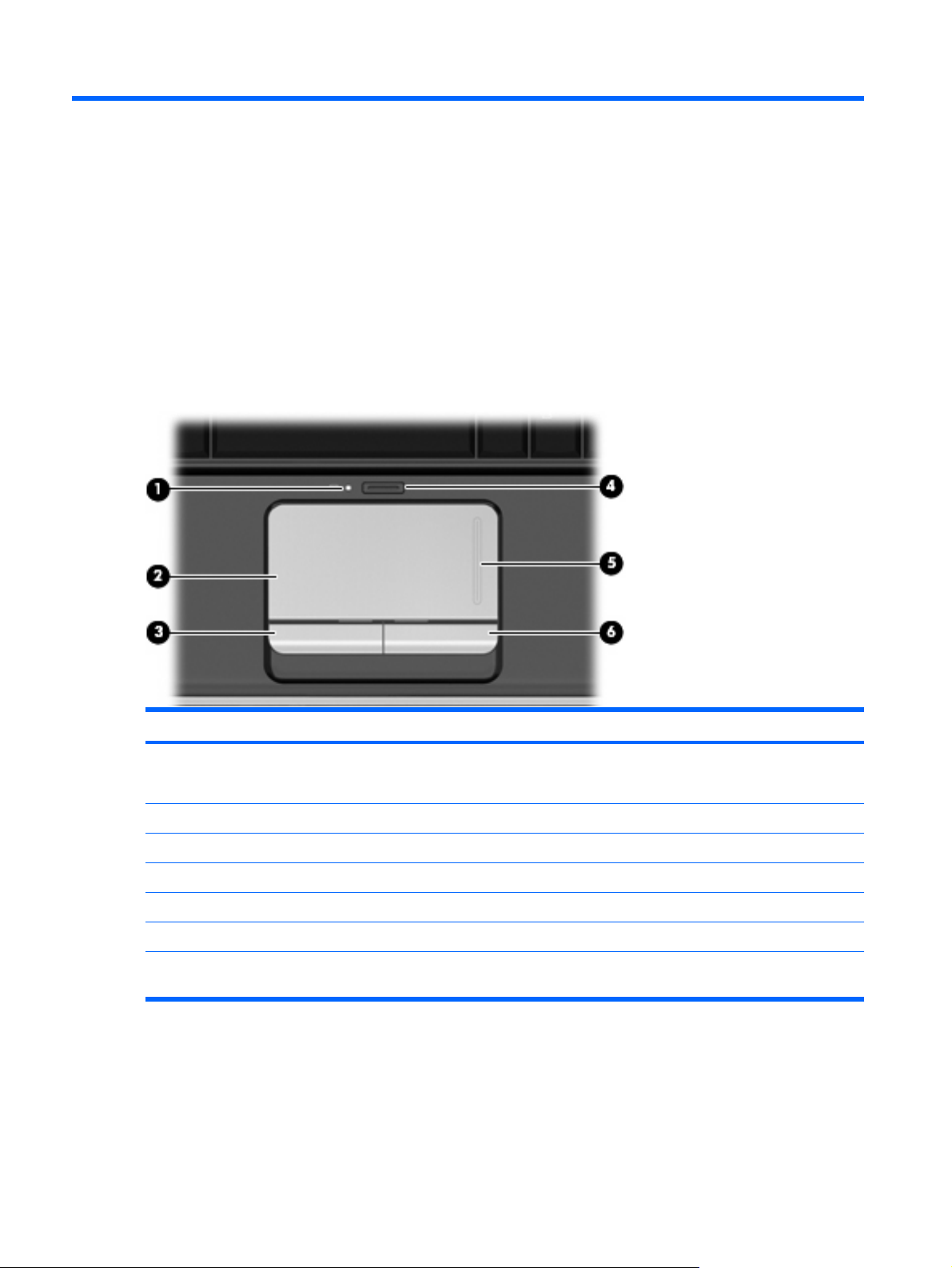
TouchPad
Component Description
(1) TouchPad light
(2) TouchPad* Moves the pointer and selects or activates items on the screen.
(3) Left TouchPad button* Functions like the left button on an external mouse.
(4) TouchPad on/off button Enables/disables the TouchPad.
(5) TouchPad vertical scroll zone Scrolls up or down.
(6) Right TouchPad button* Functions like the right button on an external mouse.
*This table describes factory settings. To view and change TouchPad preferences, select Start > Control Panel > Hardware
and Sound > Mouse.
White: TouchPad is enabled.
●
Amber: TouchPad is disabled.
●
6 Chapter 2 External component identification
Page 15
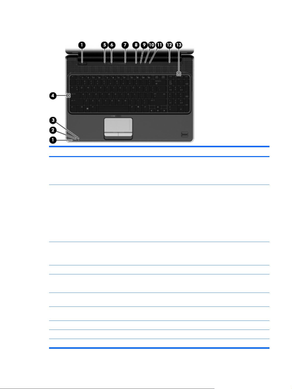
Lights
Component Description
(1) Power lights* (2)
(2) Battery light
(3) Drive light
(4) Caps lock light On: Caps lock is on.
(5) Volume mute light
(6) Volume down light On: The volume scroll zone is being used to decrease speaker
On: The computer is on.
●
Blinking: The computer is in the Sleep state.
●
Off: The computer is off or in Hibernation.
●
On: A battery is charging.
●
Blinking: A battery that is the only available power source has
●
reached a low battery level. When the battery reaches a
critical battery level, the battery light begins blinking rapidly.
Off: If the computer is plugged into an external power source,
●
the light is turned off when all batteries in the computer are
fully charged. If the computer is not plugged into an external
power source, the light stays off until the battery reaches a
low battery level.
Blinking: The hard drive or optical drive is being accessed.
●
Amber: HP ProtectSmart Hard Drive Protection has
●
temporarily parked the hard drive.
White: Computer sound is turned on.
●
Amber: Computer sound is turned off.
●
volume.
(7) Volume up light On: The volume scroll zone is being used to increase speaker
volume.
(8) Previous/rewind light (select models only) On: The previous/rewind button has been pressed.
(9) Play/pause light (select models only) On: The play/pause button has been pressed.
(10) Next/fast forward light (select models only) On: The next/fast forward button has been pressed.
Top components 7
Page 16

Component Description
(11) Stop light (select models only) On: The stop button has been pressed.
(12) Wireless light
(13) Num lock light On: The integrated numeric keypad is enabled, or num lock is
*The 2 power lights display the same information. The light on the power button is visible only when the computer is open. The
power light on the front of the computer is visible whether the computer is open or closed.
Blue: An integrated wireless device, such as a wireless local
●
area network (WLAN) device and/or a Bluetooth® device, is
turned on.
Amber: All wireless devices are turned off.
●
enabled on a connected optional numeric keypad.
8 Chapter 2 External component identification
Page 17
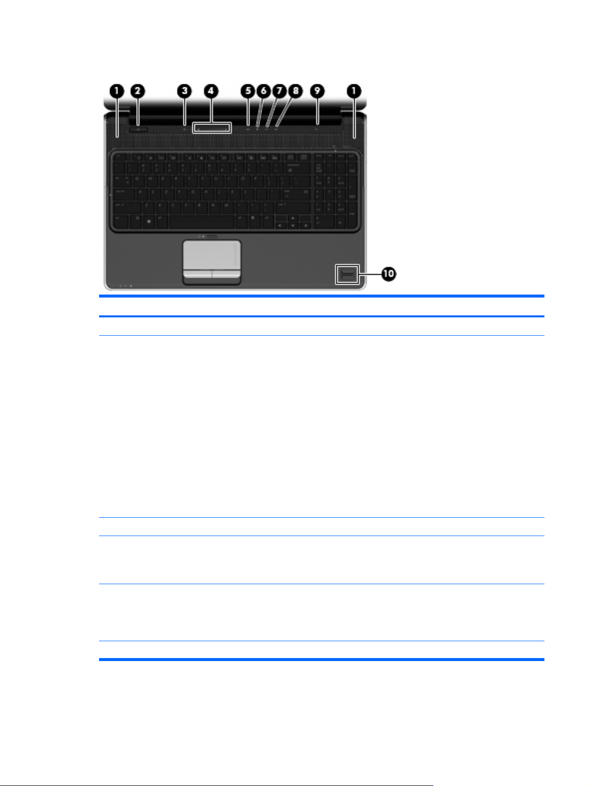
Buttons, speakers and fingerprint reader
Component Description
(1) Speakers (2) Produce sound.
(2) Power button*
(3) Volume mute button Mutes and restores speaker sound.
(4) Volume scroll zone Adjusts speaker volume. Slide your finger to the left to decrease
(5) Previous/rewind button (select models only)
When the computer is off, press the button to turn on the
●
computer.
When the computer is on, press the button briefly to initiate
●
Sleep.
When the computer is in the Sleep state, press the button
●
briefly to exit Sleep.
When the computer is in Hibernation, press the button briefly
●
to exit Hibernation.
If the computer has stopped responding and Windows® shutdown
procedures are ineffective, press and hold the power button for at
least 5 seconds to turn off the computer.
To learn more about your power settings, select Start > Control
Panel > System and Maintenance > Power Options.
volume and to the right to increase volume. You can also tap the
minus sign (-) on the scroll zone to decrease volume, or tap the
plus sign (+) on the scroll zone to increase volume.
Plays the previous track or chapter when the button is pressed
●
once.
Rewinds media when the button is pressed simultaneously
●
with the fn key.
(6) Play/pause button (select models only) Plays or pauses media.
Top components 9
Page 18

Component Description
(7) Next/fast forward button (select models only)
(8) Stop button (select models only) Stops playback.
(9) Wireless button Turns the wireless feature on or off, but does not create a wireless
(10) Fingerprint reader (select models only) Allows a fingerprint logon to Windows, instead of a password logon.
*This table describes factory settings. For information about changing factory settings, refer to the user guides located in Help
and Support.
Plays the next track or chapter when the button is pressed
●
once.
Fast forwards media when pressed simultaneously with the
●
fn key.
connection.
NOTE: A wireless network must be set up in order to establish a
wireless connection.
10 Chapter 2 External component identification
Page 19
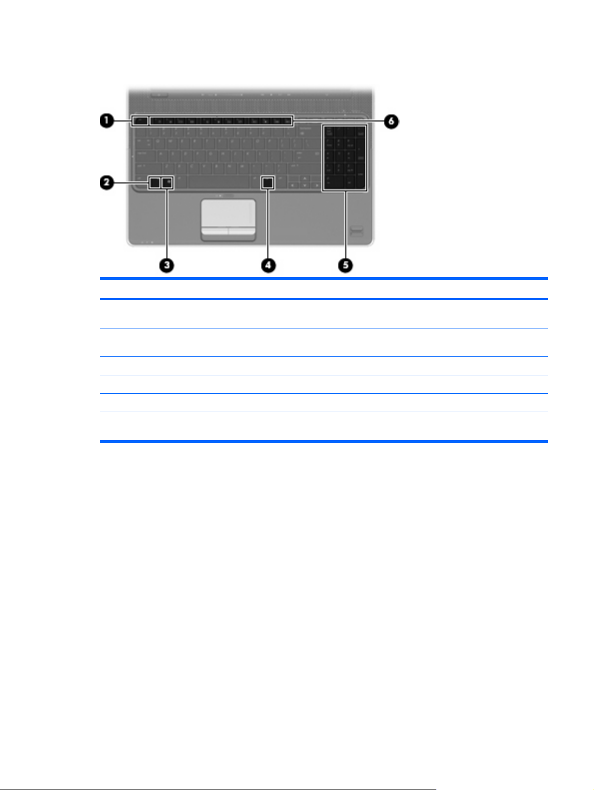
Keys
Component Description
(1) esc key Displays system information about your computer when pressed in
combination with the fn key.
(2) fn key Executes frequently used system functions when pressed in
(3) Windows logo key Displays the Windows Start menu.
(4) Windows applications key Displays a shortcut menu for items beneath the pointer.
(5) Integrated numeric keypad keys Can be used like the keys on an external numeric keypad.
(6) Function keys Execute frequently used system functions when pressed in
combination with a function key or the esc key.
combination with the fn key.
Top components 11
Page 20
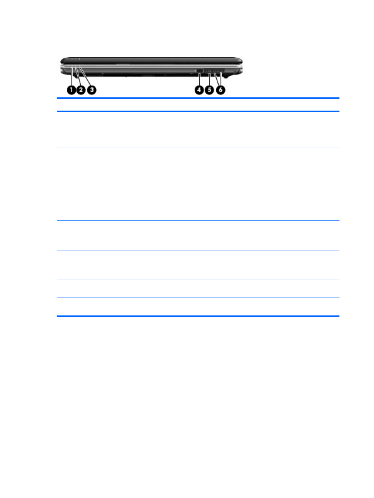
Front components
Component Description
(1) Power light
(2) Battery light
(3) Drive light
(4) Consumer infrared lens Receives a signal from the remote control.
(5) Audio-in (microphone) jack Connects an optional computer headset microphone, stereo array
(6) Audio-out (headphone) jacks (2) Produce sound when connected to optional powered stereo
On: The computer is on.
●
Blinking: The computer is in the Sleep state.
●
Off: The computer is off or in Hibernation.
●
On: A battery is charging.
●
Blinking: A battery that is the only available power source has
●
reached a low battery level. When the battery reaches a
critical battery level, the battery light begins blinking rapidly.
Off: If the computer is plugged into an external power source,
●
the light is turned off when all batteries in the computer are
fully charged. If the computer is not plugged into an external
power source, the light stays off until the battery reaches a low
battery level.
Blinking: The hard drive or optical drive is being accessed.
●
Amber: HP ProtectSmart Hard Drive Protection has
●
temporarily parked the hard drive.
microphone, or monaural microphone.
speakers, headphones, ear buds, a headset, or television audio.
NOTE: This table describes factory settings. For information about changing factory settings, refer to the user guides located
in Help and Support.
12 Chapter 2 External component identification
Page 21
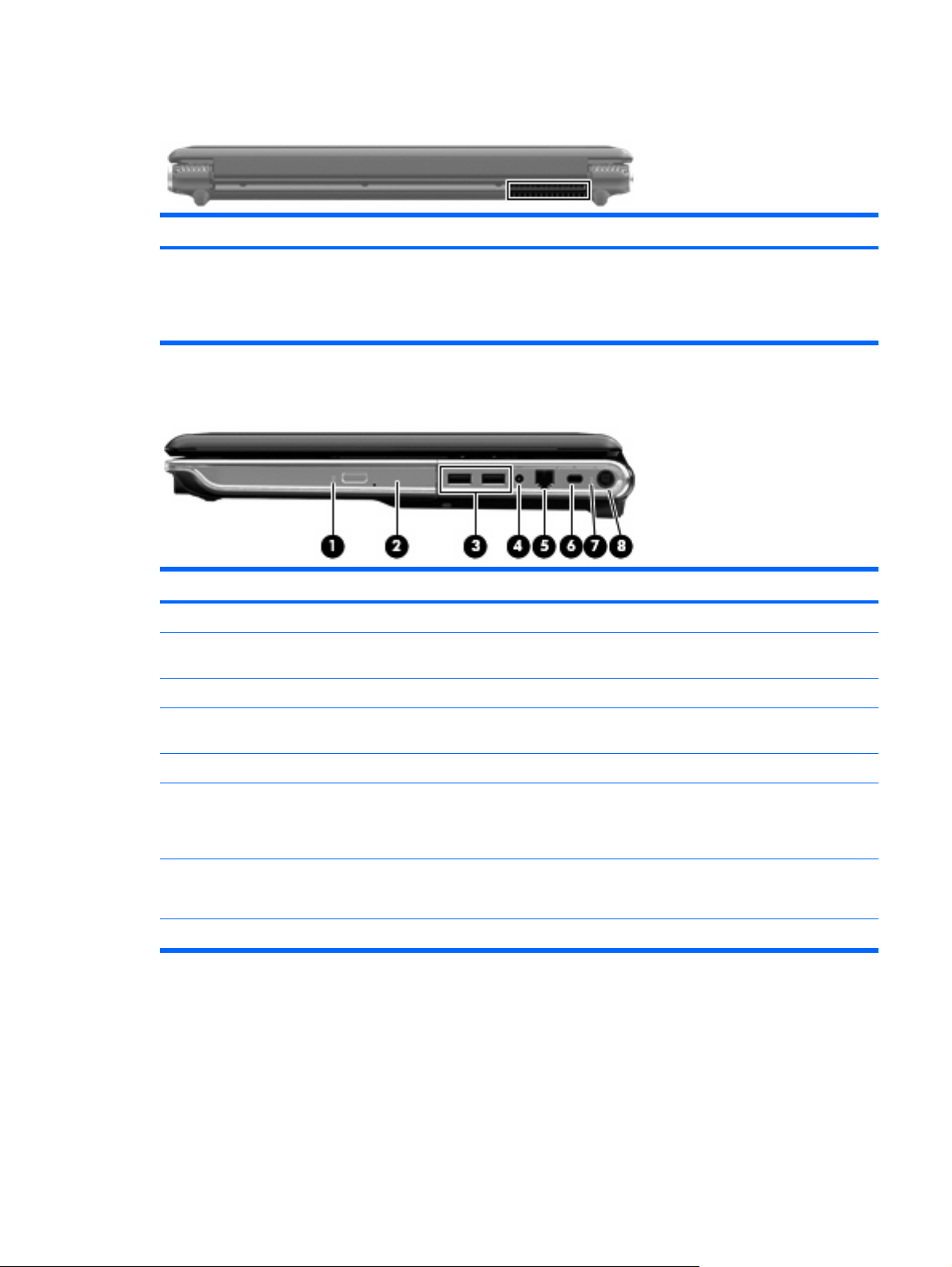
Rear component
Component Description
Vent Enables airflow to cool internal components.
Right-side components
NOTE: The computer fan starts up automatically to cool internal
components and prevent overheating. It is normal for the internal
fan to cycle on and off during routine operation.
Component Description
(1) Optical drive light Blinking: The optical drive is being accessed.
(2) Optical drive Reads optical discs and, on select models, also writes to optical
(3) USB ports (2) Connect optional USB devices.
(4) TV antenna/cable jack (select models only) Connects a TV antenna, a digital cable device, or a satellite device
(5) RJ-11 (modem) jack (select models only) Connects a modem cable.
(6) Security cable slot Attaches an optional security cable to the computer.
(7) AC adapter light
(8) Power connector Connects an AC adapter.
discs.
that receives standard or high-definition TV broadcasts.
NOTE: The security cable is designed to act as a deterrent, but
it may not prevent the computer from being mishandled or stolen.
On: The computer is connected to external power.
●
Off: The computer is not connected to external power.
●
Rear component 13
Page 22
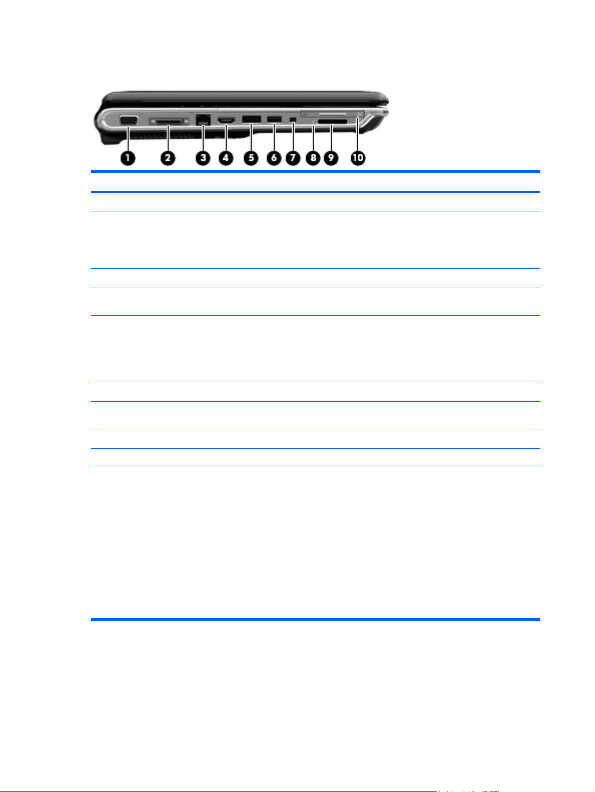
Left-side components
Component Description
(1) External monitor port Connects an external VGA monitor or projector.
(2) Expansion port 3 Connects the computer to an optional docking device or an optional
(3) RJ-45 (network) jack Connects a network cable.
expansion product.
NOTE: The computer has only one expansion port. The term
expansion port 3 describes the type of expansion port.
(4) HDMI port Connects an optional video or audio device, such as a high-
(5) eSATA/USB port (select models only) Connects an optional high-performance eSATA component, such
(6) USB port Connects an optional USB device.
(7) 1394 port (select models only) Connects an optional IEEE 1394 or 1394a device, such as a
(8) Digital Media Slot light Blinking: The media card is being accessed.
(9) ExpressCard slot Supports optional ExpressCard/54 cards.
(10) Digital Media Slot Supports the following optional digital card formats:
definition television, or any compatible digital or audio component.
as an eSATA external hard drive, or connects an optional USB
device.
NOTE: Depending on your computer model, the computer may
include a USB port only.
camcorder.
Memory Stick (MS)
●
Memory Stick Pro (MSP)
●
MultiMediaCard (MMC)
●
Secure Digital (SD) Memory Card
●
xD-Picture Card (XD)
●
14 Chapter 2 External component identification
xD-Picture Card (XD) Type H
●
xD-Picture Card (XD) Type M
●
Page 23

Bottom components
Component Description
(1) Hard drive bay Holds the hard drive.
(2) Vents (8) Enable airflow to cool internal components.
NOTE: The computer fan starts up automatically to cool internal
components and prevent overheating. It is normal for the internal
fan to cycle on and off during routine operation.
(3) Battery bay Holds the battery.
(4) Memory module compartment Contains the memory module slots.
Also holds the WLAN module, TV tuner card (select models only),
and the Intel® Turbo Memory card (select models only).
CAUTION: To prevent an unresponsive system, replace the
wireless module only with a wireless module authorized for use in
the computer by the governmental agency that regulates wireless
devices in your country or region. If you replace the module and
then receive a warning message, remove the module to restore
computer functionality, and then contact technical support through
Help and Support.
(5) Battery release latch Releases the battery from the battery bay.
Bottom components 15
Page 24
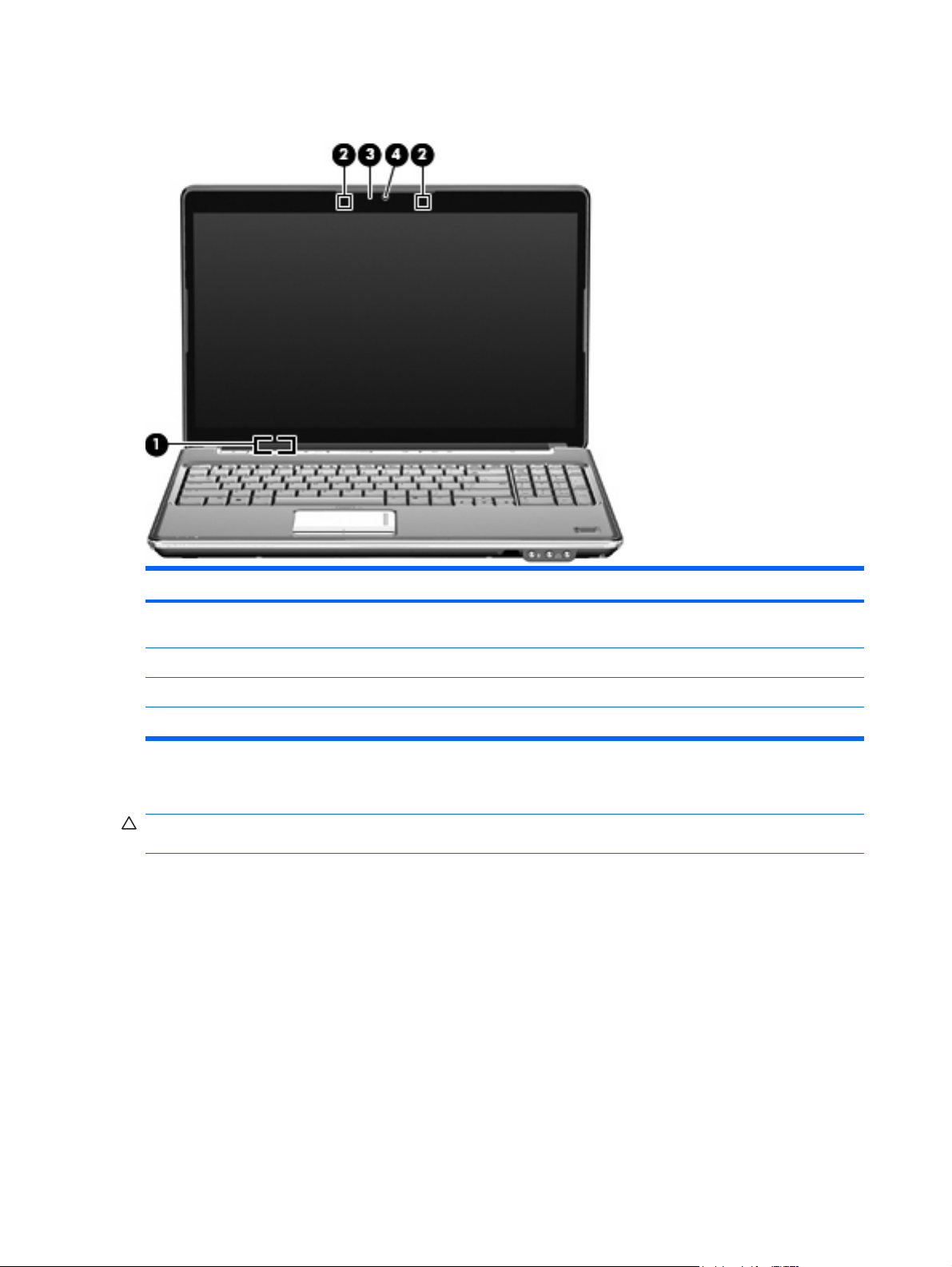
Display components
Component Description
(1) Internal display switch Turns off the display and initiates Sleep if the display is closed while
(2) Internal microphones (2) Record sound.
(3) Webcam light On: The webcam is in use.
(4) Integrated webcam Records audio and video and captures still photographs.
Cleaning the display
CAUTION: To prevent permanent damage to the computer, never spray water, cleaning fluids, or
chemicals on the display.
To remove smudges and lint, frequently clean the display with a soft, damp, lint-free cloth. If the screen
requires additional cleaning, use premoistened antistatic wipes or an antistatic screen cleaner.
the power is on.
16 Chapter 2 External component identification
Page 25

Wireless antennas (select models only)
On select computers, at least 2 antennas send and receive signals from one or more wireless devices.
NOTE: The antennas are not visible from the outside of the computer. For optimal transmission, keep
the areas immediately around the antennas free from obstructions.
To see wireless regulatory notices, refer to the section of the Regulatory, Safety and Environmental
Notices that applies to your country or region. These notices are located in Help and Support.
Wireless antennas (select models only) 17
Page 26

3 Illustrated parts catalog
Service tag
When ordering parts or requesting information, provide the computer serial number and model
description provided on the service tag.
(1) Product name: This is the product name affixed to the front of the computer.
(2) Serial number (s/n): This is an alphanumeric identifier that is unique to each product.
(3) Part number/Product number (p/n): This number provides specific information about the product's
hardware components. The part number helps a service technician to determine what components and
parts are needed.
(4) Model description: This is the alphanumeric identifier used to locate documents, drivers, and support
for the computer.
(5) Warranty period: This number describes the duration of the warranty period for the computer.
18 Chapter 3 Illustrated parts catalog
Page 27
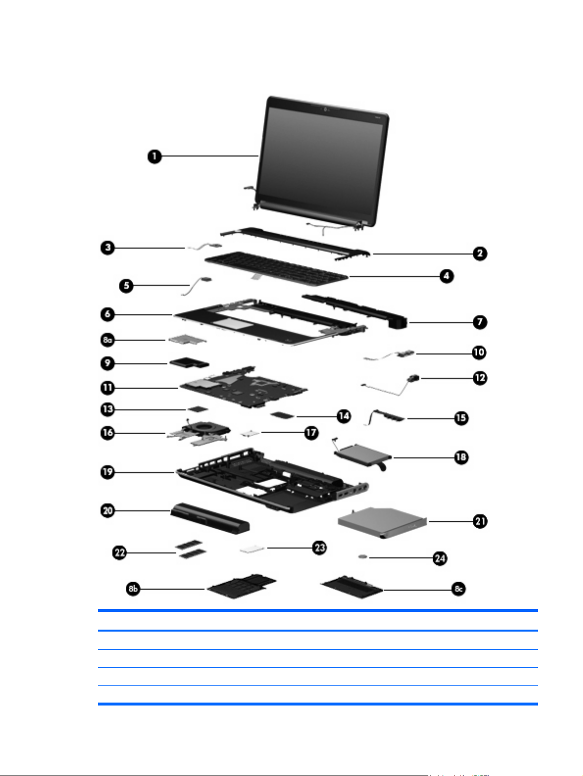
Computer major components
Item Description Spare part number
(1) Display assembly (includes webcam, 2 microphones, and 2 wireless antenna transceivers and cables)
16.0-inch WXGA BrightView display assemblies:
For use in white computers
●
For use in black computers 512358-001
●
512357-001
Computer major components 19
Page 28

Item Description Spare part number
16.0-inch WXGA AntiGlare display assemblies:
15.6-inch WXGA BrightView display assemblies:
15.6-inch WXGA AntiGlare display assemblies:
LED display for use in white computers
●
LED display for use in black computers
●
LED display for use in MTV2 artist edition computers
●
For use in white computers
●
For use in black computers
●
LED display assembly for use in white computers
●
LED display assembly for use in black computers
●
LED display assembly for use in MTV2 artist edition computers
●
For use in white computers
●
For use in black computers
●
LED display for use in white computers
●
LED display for use in black computers
●
For use in white computers
●
538349-001
538351-001
518771-001
518772-001
573304-001
538355-001
538313-001
538315-001
517862-001
518775-001
538348-001
538350-001
518776-001
NOTE: See Display assembly componentson page 26 for more information on display assembly spare part
(2)
For use in white computers 518110-001
For use in black computers 518790-001
For use in MTV2 artist edition computers 570205-001
(3) Power button board (includes cable) 512834-001
(4) Keyboard (includes keyboard cable)
White molded keyboard 517863-xxx
Black painted keyboard 518965-xxx
Black molded keyboard 518966-xxx
For use in black computers
●
LED display for use in white computers
●
LED display for use in black computers
●
LED display for use in MTV2 artist edition computers
●
numbers.
Switch cover (includes LED board and cable)
NOTE: For a detailed list of available keyboards, see
White painted keyboard 517864-xxx
Sequential part number listing on page 31.
518777-001
538312-001
538314-001
538354-001
Black textured keyboard 570228-xxx
(5) Bluetooth module 483113-001
20 Chapter 3 Illustrated parts catalog
Page 29

Item Description Spare part number
(6) Top cover (includes TouchPad and TouchPad buttons)
For use only with white computers not equipped with a fingerprint reader 518108-001
For use only with black computers equipped with a fingerprint reader 518789-001
For use only with black computers not equipped with a fingerprint reader 518788-001
For use only with MTV2 artist edition computers 570206-001
(7) Speaker assembly 533865-001
Plastics Kit, includes: 511890-001
(8a)
(8b)
(8c)
(9) ExpressCard module 464793-002
(10) USB board (includes cable) 516497-001
(11) System board (includes replacement thermal material)
For use with computers equipped with discrete graphics subsystem memory with 1 GB
For use only with white computers equipped with a fingerprint reader 518109-001
ExpressCard slot bezel
Memory module cover
Hard drive cover
NOTE: See
For use with computers equipped with UMA graphics subsystem memory 509449-001
of dedicated memory
Plastics Kit on page 28 for more information.
509450-001
For use with computers equipped with discrete graphics subsystem memory with 512
MB of dedicated memory
For use with computers equipped with SidePort memory 570379-001
(12) Power connector cable 533465-001
(13) Processor (includes replacement thermal material)
AMD Turion Ultra ZM-86, 2.40-GHz with 2-MB L2 cache 507974-001
AMD Turion Ultra ZM-85, 2.30-GHz with 2-MB L2 cache 532119-001
AMD Turion Ultra ZM-84, 2.30-GHz with 2-MB L2 cache 507975-001
AMD Turion Ultra ZM-82, 2.20-GHz with 2-MB L2 cache 507973-001
AMD Turion RM-77, 2.30-GHz with 1-MB L2 cache 572565-001
AMD Turion RM-75, 2.20-GHz with 1-MB L2 cache 532120-001
AMD Turion RM-74, 2.20-GHz with 1-MB L2 cache 507979-001
AMD Athlon QL-67, 2.20-GHz with 1-MB L2 cache 572566-001
AMD Athlon QL-65, 2.10-GHz with 1-MB L2 cache 532121-001
AMD Athlon QL-64, 2.10-GHz with 1-MB L2 cache 506053-001
AMD Sempron SI-42, 2.1-GHz with 512-KB L2 cache 508102-001
AMD Turion Ultra ZM-87, 2.40-GHz with 2-MB L2 cache 572564-001
509451-001
Computer major components 21
Page 30

Item Description Spare part number
(14) WLAN module
Atheros 9285G 802.11b/g WiFi Adapter for use in Afghanistan, Albania, Algeria,
Atheros 9285G 802.11b/g WiFi Adapter for use in Canada, the Cayman Islands, Guam,
Puerto Rico, the United States, and the U.S. Virgin Islands
Andorra, Angola, Antigua and Barbuda, Argentina, Armenia, Aruba, Australia, Austria,
Azerbaijan, the Bahamas, Bahrain, Barbados, Belgium, Belize, Benin, Bermuda,
Bhutan, Bosnia and Herzegovina, Botswana, Brazil, the British Virgin Islands, Brunei,
Bulgaria, Burkina Faso, Burundi, Cambodia, Cameroon, Cape Verde, the Central
African Republic, Chad, Chile, Colombia, Comoros, the Congo, Costa Rica, Croatia,
Cyprus, the Czech Republic, Djibouti, Dominica, the Dominican Republic, East Timor,
Ecuador, Egypt, El Salvador, Equatorial Guinea, Eritrea, Estonia, Ethiopia, Fiji, Finland,
France, French Guiana, Gabon, Gambia, Georgia, Germany, Ghana, Gibraltar,
Greece, Grenada, Guadeloupe, Guatemala, Guinea, Guinea-Bissau, Guyana, Haiti,
Honduras, Hong Kong, Hungary, Iceland, India, Indonesia, Ireland, Israel, Italy, the
Ivory Coast, Jamaica, Japan, Jordan, Kazakhstan, Kenya, Kiribati, Kuwait, Kyrgyzstan,
Laos, Latvia, Lebanon, Lesotho, Liberia, Liechtenstein, Lithuania, Luxembourg,
Macedonia, Madagascar, Malawi, Malaysia, the Maldives, Mali, Malta, the Marshall
Islands, Martinique, Mauritania, Mauritius, Mexico, Micronesia, Monaco, Mongolia,
Montenegro, Morocco, Mozambique, Namibia, Nauru, Nepal, the Nether Antilles, the
Netherlands, New Zealand, Nicaragua, Niger, Nigeria, Norway, Oman, Palau, Panama,
Papua New Guinea, Paraguay, the People’s Republic of China, Peru, the Philippines,
Poland, Portugal, the Republic of Moldova, Romania, Rwanda, Samoa, San Marino,
Sao Tome and Principe, Saudi Arabia, Senegal, Serbia, the Seychelles, Sierra Leone,
Singapore, Slovakia, Slovenia, the Solomon Islands, Somalia, South Africa, South
Korea, Spain, Sri Lanka, St. Kitts and Nevis, St. Lucia, St. Vincent and the Grenadines,
Suriname, Swaziland, Sweden, Switzerland, Syria, Taiwan, Tajikistan, Tanzania, Togo,
Tonga, Trinidad and Tobago, Tunisia, Turkey, Turkmenistan, Tuvalu, Uganda, the
United Arab Emirates, the United Kingdom, Uruguay, Uzbekistan, Vanuatu, Venezuela,
Vietnam, Yemen, Zaire, Zambia, and Zimbabwe
518436-001
518436-002
Atheros 9280AGN 802.11a/b/g/n WiFi Adapter for use in Canada, the Cayman Islands,
Guam, Puerto Rico, the United States, and the U.S. Virgin Islands
Atheros 9280AGN 802.11a/b/g/n WiFi Adapter for use in Canada, the Cayman Islands,
Guam, Puerto Rico, the United States, and the U.S. Virgin Islands for use in
Afghanistan, Albania, Algeria, Andorra, Angola, Antigua and Barbuda, Argentina,
Armenia, Aruba, Australia, Austria, Azerbaijan, the Bahamas, Bahrain, Barbados,
Belgium, Belize, Benin, Bermuda, Bhutan, Bosnia and Herzegovina, Botswana, Brazil,
the British Virgin Islands, Brunei, Bulgaria, Burkina Faso, Burundi, Cambodia,
Cameroon, Cape Verde, the Central African Republic, Chad, Chile, Colombia,
Comoros, the Congo, Costa Rica, Croatia, Cyprus, the Czech Republic, Djibouti,
Dominica, the Dominican Republic, East Timor, Ecuador, Egypt, El Salvador,
Equatorial Guinea, Eritrea, Estonia, Ethiopia, Fiji, Finland, France, French Guiana,
Gabon, Gambia, Georgia, Germany, Ghana, Gibraltar, Greece, Grenada, Guadeloupe,
Guatemala, Guinea, Guinea-Bissau, Guyana, Haiti, Honduras, Hong Kong, Hungary,
Iceland, India, Indonesia, Ireland, Israel, Italy, the Ivory Coast, Jamaica, Japan, Jordan,
Kazakhstan, Kenya, Kiribati, Kuwait, Kyrgyzstan, Laos, Latvia, Lebanon, Lesotho,
Liberia, Liechtenstein, Lithuania, Luxembourg, Macedonia, Madagascar, Malawi,
Malaysia, the Maldives, Mali, Malta, the Marshall Islands, Martinique, Mauritania,
Mauritius, Mexico, Micronesia, Monaco, Mongolia, Montenegro, Morocco,
Mozambique, Namibia, Nauru, Nepal, the Nether Antilles, the Netherlands, New
Zealand, Nicaragua, Niger, Nigeria, Norway, Oman, Palau, Panama, Papua New
Guinea, Paraguay, the People’s Republic of China, Peru, the Philippines, Poland,
Portugal, the Republic of Moldova, Romania, Rwanda, Samoa, San Marino, Sao Tome
and Principe, Saudi Arabia, Senegal, Serbia, the Seychelles, Sierra Leone, Singapore,
Slovakia, Slovenia, the Solomon Islands, Somalia, South Africa, South Korea, Spain,
Sri Lanka, St. Kitts and Nevis, St. Lucia, St. Vincent and the Grenadines, Suriname,
Swaziland, Sweden, Switzerland, Syria, Taiwan, Tajikistan, Tanzania, Togo, Tonga,
Trinidad and Tobago, Tunisia, Turkey, Turkmenistan, Tuvalu, Uganda, the United Arab
Emirates, the United Kingdom, Uruguay, Uzbekistan, Vanuatu, Venezuela, Vietnam,
Yemen, Zaire, Zambia, and Zimbabwe
518437-001
518437-002
22 Chapter 3 Illustrated parts catalog
Page 31

Item Description Spare part number
Broadcom BCM4312 802.11b/g WLAN module for use only with computers in
Antigua and Barbuda, Barbados, Belize, Canada, the Cayman Islands, Guam,
Puerto Rico, Trinidad and Tobago, the U.S. Virgin Islands, and the United States
Broadcom BCM4312 802.11b/g WLAN module for use only with computers in
Afghanistan, Albania, Algeria, Andorra, Angola, Antigua and Barbuda, Argentina,
Armenia, Aruba, Australia, Austria, Azerbaijan, the Bahamas, Bahrain, Bangladesh,
Barbados, Belarus, Belgium, Belize, Benin, Bermuda, Bhutan, Bolivia,
Bosnia and Herzegovina, Botswana, Brazil, the British Virgin Islands, Brunei, Bulgaria,
Burkina Faso, Burundi, Cameroon, Cape Verde, the Central African Republic, Chad,
Chile, the People's Republic of China, Colombia, Comoros, the Congo, Costa Rica,
Croatia, Cyprus, the Czech Republic, Denmark, Djibouti, Dominica,
the Dominican Republic, East Timor, Ecuador, Egypt, El Salvador, Equitorial Guinea,
Eritrea, Estonia, Ethiopia, Fiji, Finland, France, French Guiana, Gabon, Gambia,
Georgia, Germany, Ghana, Gibraltar, Greece, Grenada, Guadeloupe, Guatemala,
Guinea, Guinea-Bissau, Guyana, Haiti, Honduras, Hong Kong, Hungary, Iceland, India,
Ireland, Israel, Italy, the Ivory Coast, Jamaica, Jordan, Kazakhstan, Kenya, Kiribati,
Kyrgyzstan, Laos, Latvia, Lebanon, Lesotho, Liberia, Liechtenstein, Lithuania,
Luxembourg, Macedonia, Madagascar, Malawi, Malaysia, the Maldives, Mali, Malta,
the Marshall Islands, Martinique, Mauritania, Mauritius, Mexico, Micronesia, Monaco,
Mongolia, Montenegro, Morocco, Mozambique, Namibia, Nauru, Nepal,
the Nether Antilles, the Netherlands, New Zealand, Nicaragua, Niger, Nigeria, Norway,
Oman, Pakistan, Palau, Panama, Papua New Guinea, Paraguay, Peru, the Philippines,
Poland, Portugal, the Republic of Moldova, Romania, Russia, Rwanda, Samoa,
San Marino, Sao Tome and Principe, Saudi Arabia, Senegal, Serbia, the Seychelles,
Sierra Leone, Singapore, Slovakia, Slovenia, the Solomon Islands, Somalia,
South Africa, South Korea, Spain, Sri Lanka, St. Kitts and Nevis, St. Lucia,
St. Vincent and the Grenadines, Suriname, Swaziland, Sweden, Switzerland, Taiwan,
Tajikistan, Tanzania, Togo, Tonga, Trinidad and Tobago, Tunisia, Turkey,
Turkmenistan, Tuvalu, Uganda, Ukraine, the United Arab Emirates,
the United Kingdom, Uruguay, Uzbekistan, Vanuatu, Venezuela, Vietnam, Yemen,
Zaire, Zambia, and Zimbabwe
504593-001
504593-002
Broadcom BCM4312 802.11b/g WLAN module for use only with computers in
Antigua and Barbuda, Barbados, Belize, Canada, the Cayman Islands, Guam,
Puerto Rico, Trinidad and Tobago, the U.S. Virgin Islands, and the United States
504664-001
Computer major components 23
Page 32

Item Description Spare part number
Broadcom BCM4312 802.11b/g WLAN module for use only with computers in
Afghanistan, Albania, Algeria, Andorra, Angola, Antigua and Barbuda, Argentina,
Armenia, Aruba, Australia, Austria, Azerbaijan, the Bahamas, Bahrain, Bangladesh,
Barbados, Belarus, Belgium, Belize, Benin, Bermuda, Bhutan, Bolivia,
Bosnia and Herzegovina, Botswana, Brazil, the British Virgin Islands, Brunei, Bulgaria,
Burkina Faso, Burundi, Cameroon, Cape Verde, the Central African Republic, Chad,
Chile, the People's Republic of China, Colombia, Comoros, the Congo, Costa Rica,
Croatia, Cyprus, the Czech Republic, Denmark, Djibouti, Dominica,
the Dominican Republic, East Timor, Ecuador, Egypt, El Salvador, Equitorial Guinea,
Eritrea, Estonia, Ethiopia, Fiji, Finland, France, French Guiana, Gabon, Gambia,
Georgia, Germany, Ghana, Gibraltar, Greece, Grenada, Guadeloupe, Guatemala,
Guinea, Guinea-Bissau, Guyana, Haiti, Honduras, Hong Kong, Hungary, Iceland, India,
Ireland, Israel, Italy, the Ivory Coast, Jamaica, Jordan, Kazakhstan, Kenya, Kiribati,
Kyrgyzstan, Laos, Latvia, Lebanon, Lesotho, Liberia, Liechtenstein, Lithuania,
Luxembourg, Macedonia, Madagascar, Malawi, Malaysia, the Maldives, Mali, Malta,
the Marshall Islands, Martinique, Mauritania, Mauritius, Mexico, Micronesia, Monaco,
Mongolia, Montenegro, Morocco, Mozambique, Namibia, Nauru, Nepal,
the Nether Antilles, the Netherlands, New Zealand, Nicaragua, Niger, Nigeria, Norway,
Oman, Pakistan, Palau, Panama, Papua New Guinea, Paraguay, Peru, the Philippines,
Poland, Portugal, the Republic of Moldova, Romania, Russia, Rwanda, Samoa,
San Marino, Sao Tome and Principe, Saudi Arabia, Senegal, Serbia, the Seychelles,
Sierra Leone, Singapore, Slovakia, Slovenia, the Solomon Islands, Somalia,
South Africa, South Korea, Spain, Sri Lanka, St. Kitts and Nevis, St. Lucia,
St. Vincent and the Grenadines, Suriname, Swaziland, Sweden, Switzerland, Taiwan,
Tajikistan, Tanzania, Togo, Tonga, Trinidad and Tobago, Tunisia, Turkey,
Turkmenistan, Tuvalu, Uganda, Ukraine, the United Arab Emirates,
the United Kingdom, Uruguay, Uzbekistan, Vanuatu, Venezuela, Vietnam, Yemen,
Zaire, Zambia, and Zimbabwe
(15) Audio/infrared board (includes cable) 511892-001
504664-002
(16) Fan/heat sink assembly (includes replacement thermal material)
For use only with computers equipped with UMA graphics subsystems 532142-001
(17) Modem module
For use only in Australia and New Zealand 510100-011
(18) Hard drive (includes left and right bracket rails, connector cable, Mylar cover with tab, and four rubber isolators)
250-GB, 7200-rpm (select models only) 509412-002
250-GB, 5400-rpm 509414-002
320-GB, 7200-rpm (select models only) 509413-002
320-GB, 5400-rpm 509415-002
500-GB, 5400-rpm 509417-002
Hard Drive Hardware Kit (not illustrated, includes left and right bracket rails, connector
For use only with computers equipped with discrete graphics subsystems 532141-001
NOTE: The modem module spare part kit does not include a modem module cable. The modem module cable is
included in the Cable Kit, spare part number 533466-001. For more information, see Cable Kit on page 29.
For use in all countries and regions except Australia and New Zealand 510100-001
160-GB, 5400-rpm 537950-001
483862-001
cable, Mylar cover with tab, and 4 rubber isolators)
(19) Base enclosure (includes rubber feet)
24 Chapter 3 Illustrated parts catalog
Page 33

Item Description Spare part number
For use in computers with discrete graphics subsystems 532139-001
For use in computers with UMA graphics subsystems 532140-001
Rubber Feet Kit (not illustrated, includes 4 base enclosure rubber feet) 516499-001
(20) Battery
6-cell, 55-Wh, 2.55-Ah Li-ion battery 509459-001
6-cell, 47-Wh, 2.20-Ah Li-ion battery 509458-001
(21) Optical drive (includes bezel and bracket)
Blu-ray ROM DVD±R/RW SuperMulti Double-Layer Drive 509420-002
Blu-ray ROM with LightScribe DVD±R/RW SuperMulti Double-Layer Drive 509421-002
(22) Memory modules (DDR2, 800 MHz, PC2-6400, 1 DIMM):
2 GB 509410-002
1 GB 509411-002
(23) TV tuner module
TV tuner external antenna cable (not illustrated)
12-cell, 95-Wh, 8.8-Ah Li-ion battery 509460-001
DVD±RW and CD-RW SuperMulti Double-Layer Combo Drive 509419-002
4 GB 509409-002
NOTE: The TV tuner module spare part kit does not include a TV tuner module cable. The TV tuner module cable
is included in the Cable Kit, spare part number 533466-001.
DVB-T TV tuner module (for use only with computers equipped with discrete graphics
memory)
482899-003
(24) RTC battery 449729-001
With PAL jack 482900-002
Computer major components 25
Page 34
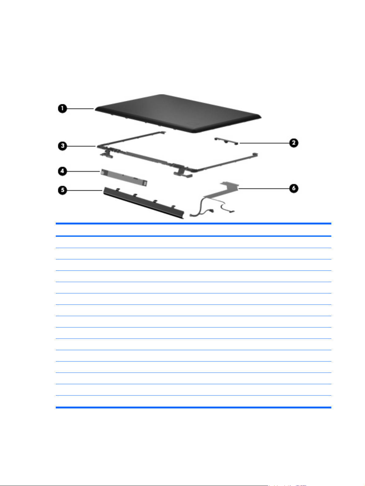
Display assembly components
The HP Pavilion dv6 Entertainment PC offers two types of display assemblies. Component spare parts
are listed in this section for AntiGlare display assemblies and BrightView display assemblies.
AntiGlare display assembly spare parts
Item Description Spare part number
(1) Display enclosure (includes wireless antenna transceivers and cables)
For use in white computers without LED displays 517861-001
For use in black computers without LED display 518774-001
For use in white computers with LED displays 570392-001
For use in black computers with LED displays 570393-001
For use in MTV2 artist edition computers 570394-001
(2) Webcam/microphone module (includes cable) 512827-001
(3) Display Hinge Kit (includes left and right hinges)
For use in computers with a 16.0-inch display 513477-001
For use in computers with a 15.6-inch display 519209-001
(4) Display inverter 488317-001
(5) Display inverter cover 533464-001
(6) Display cable 512825-001
Display Rubber Kit (not illustrated, includes display bezel rubber screw covers) 513479-001
Display Screw Kit (not illustrated) 512362-001
26 Chapter 3 Illustrated parts catalog
Page 35

BrightView display assembly spare parts
Item Description Spare part number
(1) Display bezel (includes logo and display lid switch actuator magnet)
For use with computers equipped with 16-inch displays 512359-001
For use with computers equipped with 15.6-inch displays 512364-001
(2) Webcam/microphone module (includes cable) 512827-001
(3) BrightView display panel (includes display panel cable)
For use only with computers equipped with 15.6-inch non-LED display panels 512363-001
For use only with computers equipped with 16-inch LED display panels 570094-001
For use only with computers equipped with 15.6-inch LED display panels 570095-001
(4) Display Hinge Kit (includes left and right hinges)
For use only with computers equipped with 16-inch display panels 512360-001
For use only with computers equipped with 15.6-inch display panels 512365-001
(5) Display inverter 488317-001
(6a) Display cable 512825-001
(6b) Wireless antenna cable (included with display enclosure)
For use only with computers equipped with 16-inch non-LED display panels 511868-001
(6c) Webcam/microphone cable (included with webcam/microphone module)
Display assembly components 27
Page 36

Item Description Spare part number
(7) Display enclosure (includes wireless antenna transceivers and cables and logo LED
board and cable)
For use in white computers 517860-001
For use in black computers 518773-001
For use in white computers with LED displays 570390-001
For use in black computers with LED displays 570391-001
For use in MTV2 artist edition computers 573305-001
Display Rubber Kit (not illustrated, includes display bezel rubber screw covers) 512361-001
Display Screw Kit (not illustrated) 512362-001
Plastics Kit
Item Description Spare part number
Plastics Kit 511890-001
(1) ExpressCard slot bezel
(2) Hard drive cover (includes 2 captive screws secured by C-clips)
(3) Memory module compartment cover (includes 3 captive screws secured by C-clips)
28 Chapter 3 Illustrated parts catalog
Page 37

Cable Kit
Item Description Spare part number
Cable Kit 533466-001
(1) Fingerprint reader cable
(2) Audio/Infrared module cable
(3) Modem module cable (includes RJ-11 jack)
(4) USB cable
(5) TV tuner module cable
Cable Kit 29
Page 38

Miscellaneous parts
Description Spare part number
Notebook sleeve, 16-inch, white 533534-001
AC adapters
65-W AC adapter
90-W AC adapter 463955-001
Power cords:
Argentina 490371-D01
Australia and New Zealand 490371-011
Belgium, Bulgaria, the Czech Republic, Finland, France, Germany, Greece, Hungary, Iceland, the
Netherlands, northwest Africa, Norway, Poland, Portugal, Russia, Slovakia, Spain, Sweden, and
Turkey
Brazil 490371-201
Asia/Pacific region, French Canada, Latin America, Thailand, and the United States 490371-001
Denmark 490371-081
India 490371-D61
Italy 490371-061
Japan 490371-291
South Africa 490371-AR1
South Korea 490371-AD1
Switzerland 490371-111
463958-001
490371-021
Taiwan 490371-AB1
The United Kingdom and Hong Kong 490371-031
Remote controls
Full-function remote control with teletext
Headset, wired with volume control 371693-001
465541-001
30 Chapter 3 Illustrated parts catalog
Page 39

Description Spare part number
Wireless laser mouse 430958-001
Screw Kit
Phillips PM2.0×3.0 screws
●
Phillips PM2.0×14.0 captive screws
●
Phillips PM2.5×3.0 screws
●
Phillips PM2.5×4.0 screws
●
Phillips PM2.5×5.0 screws
●
Phillips PM2.5×5.0 captive screws
●
Phillips PM2.5×5.5 captive screws
●
Phillips PM2.5×6.5 screws
●
Phillips PM3.0×3.5 screws
●
Sequential part number listing
Spare part
number
371693-001 Headset, wired with volume control
Description
516498-001
430958-001 Wireless laser mouse
449729-001 RTC battery
463955-001 90-W AC adapter
463958-001 65-W AC adapter
464793-002 ExpressCard module
465541-001 Full-function remote control with teletext
482899-003 DVB-T TV tuner module (for use only with computers equipped with discrete graphics memory)
482900-002 TV tuner external antenna cable with PAL jack
483113-001 Bluetooth module
483862-001 Hard Drive Hardware Kit (includes left and right bracket rails, connector cable, Mylar cover with tab, and
4 rubber isolators)
488317-001 Display inverter
489822-001 Bluetooth cable
490371-001 Power cord for use in the Asia/Pacific region, French Canada, Latin America, Thailand, and the United
490371-011 Power cord for use in Australia and New Zealand
490371-021 Power cord for use in Belgium, Bulgaria, the Czech Republic, Finland, France, Germany, Greece,
States
Hungary, Iceland, the Netherlands, northwest Africa, Norway, Poland, Portugal, Russia, Slovakia, Spain,
Sweden, and Turkey
Sequential part number listing 31
Page 40

Spare part
number
490371-031 Power cord for use in the United Kingdom and Hong Kong
490371-061 Power cord for use in Italy
490371-081 Power cord for use in Denmark
490371-111 Power cord for use in Switzerland
490371-201 Power cord for use in Brazil
490371-291 Power cord for use in Japan
490371-AB1 Power cord for use in Taiwan
490371-AD1 Power cord for use in South Korea
490371-AR1 Power cord for use in South Africa
490371-D01 Power cord for use in Argentina
490371-D61 Power cord for use in India
504593-001 Broadcom BCM4312 802.11b/g WLAN module for use only with computers in Antigua and Barbuda,
504593-002 Broadcom BCM4312 802.11b/g WLAN module for use only with computers in Afghanistan, Albania,
Description
Barbados, Belize, Canada, the Cayman Islands, Guam, Puerto Rico, Trinidad and Tobago,
the U.S. Virgin Islands, and the United States
Algeria, Andorra, Angola, Antigua and Barbuda, Argentina, Armenia, Aruba, Australia, Austria, Azerbaijan,
the Bahamas, Bahrain, Bangladesh, Barbados, Belarus, Belgium, Belize, Benin, Bermuda, Bhutan,
Bolivia, Bosnia and Herzegovina, Botswana, Brazil, the British Virgin Islands, Brunei, Bulgaria,
Burkina Faso, Burundi, Cameroon, Cape Verde, the Central African Republic, Chad, Chile,
the People's Republic of China, Colombia, Comoros, the Congo, Costa Rica, Croatia, Cyprus,
the Czech Republic, Denmark, Djibouti, Dominica, the Dominican Republic, East Timor, Ecuador, Egypt,
El Salvador, Equitorial Guinea, Eritrea, Estonia, Ethiopia, Fiji, Finland, France, French Guiana, Gabon,
Gambia, Georgia, Germany, Ghana, Gibraltar, Greece, Grenada, Guadeloupe, Guatemala, Guinea,
Guinea-Bissau, Guyana, Haiti, Honduras, Hong Kong, Hungary, Iceland, India, Ireland, Israel, Italy,
the Ivory Coast, Jamaica, Jordan, Kazakhstan, Kenya, Kiribati, Kyrgyzstan, Laos, Latvia, Lebanon,
Lesotho, Liberia, Liechtenstein, Lithuania, Luxembourg, Macedonia, Madagascar, Malawi, Malaysia,
the Maldives, Mali, Malta, the Marshall Islands, Martinique, Mauritania, Mauritius, Mexico, Micronesia,
Monaco, Mongolia, Montenegro, Morocco, Mozambique, Namibia, Nauru, Nepal, the Nether Antilles,
the Netherlands, New Zealand, Nicaragua, Niger, Nigeria, Norway, Oman, Pakistan, Palau, Panama,
Papua New Guinea, Paraguay, Peru, the Philippines, Poland, Portugal, the Republic of Moldova,
Romania, Russia, Rwanda, Samoa, San Marino, Sao Tome and Principe, Saudi Arabia, Senegal, Serbia,
the Seychelles, Sierra Leone, Singapore, Slovakia, Slovenia, the Solomon Islands, Somalia, South Africa,
South Korea, Spain, Sri Lanka, St. Kitts and Nevis, St. Lucia, St. Vincent and the Grenadines, Suriname,
Swaziland, Sweden, Switzerland, Taiwan, Tajikistan, Tanzania, Togo, Tonga, Trinidad and Tobago,
Tunisia, Turkey, Turkmenistan, Tuvalu, Uganda, Ukraine, the United Arab Emirates, the United Kingdom,
Uruguay, Uzbekistan, Vanuatu, Venezuela, Vietnam, Yemen, Zaire, Zambia, and Zimbabwe
504664-001 Broadcom BCM4312 802.11b/g WLAN module for use only with computers in Antigua and Barbuda,
Barbados, Belize, Canada, the Cayman Islands, Guam, Puerto Rico, Trinidad and Tobago,
the U.S. Virgin Islands, and the United States
32 Chapter 3 Illustrated parts catalog
Page 41

Spare part
number
Description
504664-002 Broadcom BCM4312 802.11b/g WLAN module for use only with computers in Afghanistan, Albania,
506053-001 AMD Athlon QL-64, 2.10-GHz processor with 1-MB L2 cache
507973-001 AMD Turion Ultra ZM-82, 2.20-GHz processor with 2-MB L2 cache
507974-001 AMD Turion Ultra ZM-86, 2.40-GHz processor with 2-MB L2 cache
507975-001 AMD Turion Ultra ZM-84, 2.30-GHz processor with 2-MB L2 cache
Algeria, Andorra, Angola, Antigua and Barbuda, Argentina, Armenia, Aruba, Australia, Austria, Azerbaijan,
the Bahamas, Bahrain, Bangladesh, Barbados, Belarus, Belgium, Belize, Benin, Bermuda, Bhutan,
Bolivia, Bosnia and Herzegovina, Botswana, Brazil, the British Virgin Islands, Brunei, Bulgaria,
Burkina Faso, Burundi, Cameroon, Cape Verde, the Central African Republic, Chad, Chile,
the People's Republic of China, Colombia, Comoros, the Congo, Costa Rica, Croatia, Cyprus,
the Czech Republic, Denmark, Djibouti, Dominica, the Dominican Republic, East Timor, Ecuador, Egypt,
El Salvador, Equitorial Guinea, Eritrea, Estonia, Ethiopia, Fiji, Finland, France, French Guiana, Gabon,
Gambia, Georgia, Germany, Ghana, Gibraltar, Greece, Grenada, Guadeloupe, Guatemala, Guinea,
Guinea-Bissau, Guyana, Haiti, Honduras, Hong Kong, Hungary, Iceland, India, Ireland, Israel, Italy,
the Ivory Coast, Jamaica, Jordan, Kazakhstan, Kenya, Kiribati, Kyrgyzstan, Laos, Latvia, Lebanon,
Lesotho, Liberia, Liechtenstein, Lithuania, Luxembourg, Macedonia, Madagascar, Malawi, Malaysia,
the Maldives, Mali, Malta, the Marshall Islands, Martinique, Mauritania, Mauritius, Mexico, Micronesia,
Monaco, Mongolia, Montenegro, Morocco, Mozambique, Namibia, Nauru, Nepal, the Nether Antilles,
the Netherlands, New Zealand, Nicaragua, Niger, Nigeria, Norway, Oman, Pakistan, Palau, Panama,
Papua New Guinea, Paraguay, Peru, the Philippines, Poland, Portugal, the Republic of Moldova,
Romania, Russia, Rwanda, Samoa, San Marino, Sao Tome and Principe, Saudi Arabia, Senegal, Serbia,
the Seychelles, Sierra Leone, Singapore, Slovakia, Slovenia, the Solomon Islands, Somalia, South Africa,
South Korea, Spain, Sri Lanka, St. Kitts and Nevis, St. Lucia, St. Vincent and the Grenadines, Suriname,
Swaziland, Sweden, Switzerland, Taiwan, Tajikistan, Tanzania, Togo, Tonga, Trinidad and Tobago,
Tunisia, Turkey, Turkmenistan, Tuvalu, Uganda, Ukraine, the United Arab Emirates, the United Kingdom,
Uruguay, Uzbekistan, Vanuatu, Venezuela, Vietnam, Yemen, Zaire, Zambia, and Zimbabwe
507979-001 AMD Turion RM-74, 2.20-GHz processor with 1-MB L2 cache
508102-001 AMD Sempron SI-42, 2.10-GHz processor with 512-KB L2 cache
509409-002 4 GB memory module (DDR2, 800-MHz, PC2-6400, 1-DIMM)
509410-002 2 GB memory module (DDR2, 800-MHz, PC2-6400, 1-DIMM)
509411-002 1 GB memory module (DDR2, 800-MHz, PC2-6400, 1-DIMM)
509412-002 250-GB, 7200-rpm hard drive (includes left and right bracket rails, connector cable, Mylar cover with tab,
and four rubber isolators) (select models only)
509413-002 320-GB, 7200-rpm hard drive (includes left and right bracket rails, connector cable, Mylar cover with tab,
and four rubber isolators) (select models only)
509414-002 250-GB, 5400-rpm hard drive (includes left and right bracket rails, connector cable, Mylar cover with tab,
and four rubber isolators)
509415-002 320-GB, 5400-rpm hard drive (includes left and right bracket rails, connector cable, Mylar cover with tab,
and four rubber isolators)
509417-002 500-GB, 5400-rpm hard drive (includes left and right bracket rails, connector cable, Mylar cover with tab,
and four rubber isolators)
509419-002 DVD±RW and CD-RW SuperMulti Double-Layer Combo Drive
509420-002 Blu-ray ROM DVD±R/RW SuperMulti Double-Layer Drive
509421-002 Blu-ray ROM with LightScribe DVD±R/RW SuperMulti Double-Layer Drive
509449-001 System board for use with computers equipped with UMA graphics subsystem memory (includes
replacement thermal material)
Sequential part number listing 33
Page 42

Spare part
number
Description
509450-001 System board for use with computers equipped with discrete graphics subsystem memory and 1 GB of
509451-001 System board for use with computers equipped with discrete graphics subsystem memory and 512 MB
509458-001 6-cell, 47-Wh, 2.20-Ah Li-ion battery
509459-001 6-cell, 55-Wh, 2.55-Ah Li-ion battery
509460-001 12-cell, 95-Wh, 8.8-Ah Li-ion battery
510100-001 Modem module for use in all countries and regions except Australia and New Zealand
510100-011 Modem module for use only in Australia and New Zealand
511868-001 BrightView display panel for use only with computers equipped with 16-inch non-LED display panels
511890-001 Plastics Kit (see Plastics Kit on page 28)
511892-001 Audio/infrared board
512357-001 16.0-inch WXGA BrightView display assembly for use in white computers (includes webcam, 2
512358-001 16.0-inch WXGA AntiGlare display assembly for use in white computers (includes webcam, 2
512359-001 Display bezel for use with computers equipped with 16-inch displays
dedicated memory (includes replacement thermal material)
of dedicated memory (includes replacement thermal material)
(includes display panel cable)
microphones, and 2 antenna transceivers)
microphones, and 2 antenna transceivers)
512360-001 Display Hinge Kit for use only with computers equipped with 16.0-inch BrightView display panels (includes
left and right hinges)
512361-001 Display Rubber Kit for BrightView displays (includes display bezel rubber screw covers)
512362-001 Display Screw Kit
512363-001 BrightView display panel for use only with computers equipped with 15.6-inch non-LED display panels
(includes display panel cable)
512364-001 Display bezel for use with computers equipped with 15.6-inch BrightView displays (includes logo and
display lid switch actuator magnet)
512365-001 Display Hinge Kit for use only with computers equipped with 15.6-inch BrightView display panels (includes
left and right hinges)
512825-001 Display cable
512827-001 Webcam/microphone module (includes cable)
512834-001 Power button board (includes cable)
513477-001 Display Hinge Kit for 16-inch AntiGlare displays (includes left and right hinges)
513479-001 Display Rubber Kit for AntiGlare displays (includes display bezel rubber screw covers)
516497-001 USB board (includes cable)
516498-001 Screw Kit
516499-001 Rubber Feet Kit
517860-001 Display enclosure for use only with white computers equipped with BrightView display panels (includes
wireless antenna transceivers and cables and logo LED board and cable)
34 Chapter 3 Illustrated parts catalog
Page 43

Spare part
number
Description
517861-001 Display enclosure for use in white computers equipped with AntiGlare display panels (includes wireless
517862-001 15.6-inch WXGA BrightView display assembly for use in white computers (includes webcam, 2
517863-001 White molded keyboard for use in the United States
517863-031 White molded keyboard for use in the United Kingdom
517863-041 White molded keyboard for use in Germany
517863-051 White molded keyboard for use in France
517863-061 White molded keyboard for use in Italy
517863-071 White molded keyboard for use in Spain
517863-111 White molded keyboard for use in Switzerland
517863-131 White molded keyboard for use in Portugal
517863-141 White molded keyboard for use in Turkey
517863-161 White molded keyboard for use in Latin America
517863-201 White molded keyboard for use in Brazil
517863-211 White molded keyboard for use in Hungary
517863-251 White molded keyboard for use in Russia
antenna transceivers and cables)
microphones, and 2 antenna transceivers)
517863-A41 White molded keyboard for use in Belgium
517863-AB1 White molded keyboard for use in Taiwan
517863-B31 White molded keyboard for use internationally
517863-DJ1 White molded keyboard for use in Greece
517864-001 White painted keyboard for use in the United States
517864-031 White painted keyboard for use in the United Kingdom
517864-041 White painted keyboard for use in Germany
517864-051 White painted keyboard for use in France
517864-061 White painted keyboard for use in Italy
517864-071 White painted keyboard for use in Spain
517864-111 White painted keyboard for use in Switzerland
517864-121 White painted keyboard for use in French Canada
517864-131 White painted keyboard for use in Portugal
517864-141 White painted keyboard for use in Turkey
517864-161 White painted keyboard for use in Latin America
517864-171 White painted keyboard for use in Saudi Arabia
517864-211 White painted keyboard for use in Hungary
Sequential part number listing 35
Page 44

Spare part
number
517864-221 White painted keyboard for use in the Czech Republic
517864-251 White painted keyboard for use in Russia
517864-281 White painted keyboard for use in Thailand
517864-291 White painted keyboard for use in Japan
517864-A41 White painted keyboard for use in Belgium
517864-AB1 White painted keyboard for use in Taiwan
517864-AD1 White painted keyboard for use in South Korea
517864-B31 White painted keyboard for use internationally
517864-DH1 White painted keyboard for use in the Netherlands
517864-DJ1 White painted keyboard for use in Greece
518108-001 Top cover for use only with white computers not equipped with a fingerprint reader
518109-001 Top cover for use only with white computers equipped with a fingerprint reader
518110-001 Switch cover for use in white computers (includes LED board and cable)
518436-001 Atheros 9285G 802.11b/g WiFi Adapter for use in Canada, the Cayman Islands, Guam, Puerto Rico, the
Description
United States, and the U.S. Virgin Islands
518436-002 Atheros 9285G 802.11b/g WiFi Adapter for use in Afghanistan, Albania, Algeria, Andorra, Angola, Antigua
and Barbuda, Argentina, Armenia, Aruba, Australia, Austria, Azerbaijan, the Bahamas, Bahrain,
Barbados, Belgium, Belize, Benin, Bermuda, Bhutan, Bosnia and Herzegovina, Botswana, Brazil, the
British Virgin Islands, Brunei, Bulgaria, Burkina Faso, Burundi, Cambodia, Cameroon, Cape Verde, the
Central African Republic, Chad, Chile, Colombia, Comoros, the Congo, Costa Rica, Croatia, Cyprus, the
Czech Republic, Djibouti, Dominica, the Dominican Republic, East Timor, Ecuador, Egypt, El Salvador,
Equatorial Guinea, Eritrea, Estonia, Ethiopia, Fiji, Finland, France, French Guiana, Gabon, Gambia,
Georgia, Germany, Ghana, Gibraltar, Greece, Grenada, Guadeloupe, Guatemala, Guinea, GuineaBissau, Guyana, Haiti, Honduras, Hong Kong, Hungary, Iceland, India, Indonesia, Ireland, Israel, Italy,
the Ivory Coast, Jamaica, Japan, Jordan, Kazakhstan, Kenya, Kiribati, Kuwait, Kyrgyzstan, Laos, Latvia,
Lebanon, Lesotho, Liberia, Liechtenstein, Lithuania, Luxembourg, Macedonia, Madagascar, Malawi,
Malaysia, the Maldives, Mali, Malta, the Marshall Islands, Martinique, Mauritania, Mauritius, Mexico,
Micronesia, Monaco, Mongolia, Montenegro, Morocco, Mozambique, Namibia, Nauru, Nepal, the Nether
Antilles, the Netherlands, New Zealand, Nicaragua, Niger, Nigeria, Norway, Oman, Palau, Panama,
Papua New Guinea, Paraguay, the People’s Republic of China, Peru, the Philippines, Poland, Portugal,
the Republic of Moldova, Romania, Rwanda, Samoa, San Marino, Sao Tome and Principe, Saudi Arabia,
Senegal, Serbia, the Seychelles, Sierra Leone, Singapore, Slovakia, Slovenia, the Solomon Islands,
Somalia, South Africa, South Korea, Spain, Sri Lanka, St. Kitts and Nevis, St. Lucia, St. Vincent and the
Grenadines, Suriname, Swaziland, Sweden, Switzerland, Syria, Taiwan, Tajikistan, Tanzania, Togo,
Tonga, Trinidad and Tobago, Tunisia, Turkey, Turkmenistan, Tuvalu, Uganda, the United Arab Emirates,
the United Kingdom, Uruguay, Uzbekistan, Vanuatu, Venezuela, Vietnam, Yemen, Zaire, Zambia, and
Zimbabwe
518437-001 Atheros 9280AGN 802.11a/b/g/n WiFi Adapter for use in Canada, the Cayman Islands, Guam, Puerto
Rico, the United States, and the U.S. Virgin Islands
36 Chapter 3 Illustrated parts catalog
Page 45

Spare part
number
Description
518437-002 Atheros 9280AGN 802.11a/b/g/n WiFi Adapter for use in Canada, the Cayman Islands, Guam, Puerto
518771-001 16.0-inch WXGA BrightView display assembly for use in black computers (includes webcam, 2
518772-001 16.0-inch WXGA AntiGlare display assembly for use in black computers (includes webcam, 2
Rico, the United States, and the U.S. Virgin Islands for use in Afghanistan, Albania, Algeria, Andorra,
Angola, Antigua and Barbuda, Argentina, Armenia, Aruba, Australia, Austria, Azerbaijan, the Bahamas,
Bahrain, Barbados, Belgium, Belize, Benin, Bermuda, Bhutan, Bosnia and Herzegovina, Botswana, Brazil,
the British Virgin Islands, Brunei, Bulgaria, Burkina Faso, Burundi, Cambodia, Cameroon, Cape Verde,
the Central African Republic, Chad, Chile, Colombia, Comoros, the Congo, Costa Rica, Croatia, Cyprus,
the Czech Republic, Djibouti, Dominica, the Dominican Republic, East Timor, Ecuador, Egypt, El Salvador,
Equatorial Guinea, Eritrea, Estonia, Ethiopia, Fiji, Finland, France, French Guiana, Gabon, Gambia,
Georgia, Germany, Ghana, Gibraltar, Greece, Grenada, Guadeloupe, Guatemala, Guinea, GuineaBissau, Guyana, Haiti, Honduras, Hong Kong, Hungary, Iceland, India, Indonesia, Ireland, Israel, Italy,
the Ivory Coast, Jamaica, Japan, Jordan, Kazakhstan, Kenya, Kiribati, Kuwait, Kyrgyzstan, Laos, Latvia,
Lebanon, Lesotho, Liberia, Liechtenstein, Lithuania, Luxembourg, Macedonia, Madagascar, Malawi,
Malaysia, the Maldives, Mali, Malta, the Marshall Islands, Martinique, Mauritania, Mauritius, Mexico,
Micronesia, Monaco, Mongolia, Montenegro, Morocco, Mozambique, Namibia, Nauru, Nepal, the Nether
Antilles, the Netherlands, New Zealand, Nicaragua, Niger, Nigeria, Norway, Oman, Palau, Panama,
Papua New Guinea, Paraguay, the People’s Republic of China, Peru, the Philippines, Poland, Portugal,
the Republic of Moldova, Romania, Rwanda, Samoa, San Marino, Sao Tome and Principe, Saudi Arabia,
Senegal, Serbia, the Seychelles, Sierra Leone, Singapore, Slovakia, Slovenia, the Solomon Islands,
Somalia, South Africa, South Korea, Spain, Sri Lanka, St. Kitts and Nevis, St. Lucia, St. Vincent and the
Grenadines, Suriname, Swaziland, Sweden, Switzerland, Syria, Taiwan, Tajikistan, Tanzania, Togo,
Tonga, Trinidad and Tobago, Tunisia, Turkey, Turkmenistan, Tuvalu, Uganda, the United Arab Emirates,
the United Kingdom, Uruguay, Uzbekistan, Vanuatu, Venezuela, Vietnam, Yemen, Zaire, Zambia, and
Zimbabwe
microphones, and 2 antenna transceivers)
microphones, and 2 antenna transceivers)
518773-001 Display enclosure for use only with black computers equipped with BrightView display panels (includes
wireless antenna transceivers and cables and logo LED board and cable)
518774-001 Display enclosure for use in black computers with AntiGlare display panels (includes wireless antenna
518775-001 15.6-inch WXGA AntiGlare display assembly for use in white computers (includes webcam, 2
518776-001 15.6-inch WXGA BrightView display assembly for use in black computers (includes webcam, 2
518777-001 15.6-inch WXGA AntiGlare display assembly for use in black computers (includes webcam, 2
518788-001 Top cover for use only with black computers not equipped with a fingerprint reader (includes TouchPad
518789-001 Top cover for use only with black computers equipped with a fingerprint reader (includes TouchPad and
518790-001 Switch cover for use in black computers (includes LED board and cable)
518965-001 Black molded keyboard for use in the United States
518965-031 Black molded keyboard for use in the United Kingdom
518965-041 Black molded keyboard for use in Germany
518965-051 Black molded keyboard for use in France
transceivers and cables)
microphones, and 2 antenna transceivers)
microphones, and 2 antenna transceivers)
microphones, and 2 antenna transceivers)
and TouchPad buttons)
TouchPad buttons)
518965-061 Black molded keyboard for use in Italy
518965-071 Black molded keyboard for use in Spain
Sequential part number listing 37
Page 46

Spare part
number
518965-111 Black molded keyboard for use in Switzerland
518965-131 Black molded keyboard for use in Portugal
518965-141 Black molded keyboard for use in Turkey
518965-161 Black molded keyboard for use in Latin America
518965-201 Black molded keyboard for use in Brazil
518965-211 Black molded keyboard for use in Hungary
518965-221 Black molded keyboard for use in the Czech Republic
518965-251 Black molded keyboard for use in Russia
518965-A41 Black molded keyboard for use internationally
518965-AB1 Black molded keyboard for use in Taiwan
518965-DJ1 Black molded keyboard for use in Greece
518966-121 Black painted keyboard for use in French Canada
518966-171 Black painted keyboard for use in Saudi Arabia
518966-281 Black painted keyboard for use in Thailand
518966-291 Black painted keyboard for use in Japan
Description
518966-AD1 Black painted keyboard for use in South Korea
518966-DH1 Black painted keyboard for use in the Netherlands
519209-001 Display Hinge Kit for 15.6-inch AntiGlare displays (includes left and right hinges)
532119-001 AMD Turion Ultra ZM-85 2.30-GHz processor with 2-MB L2 cache
532120-001 AMD Turion RM-75 2.20-GHz processor with 1-MB L2 cache
532121-001 AMD Athlon QL-65 2.10-GHz processor with 1-MB L2 cache
532139-001 Base enclosure for use in computers with discrete graphics subsystems (includes rubber feet)
532140-001 Base enclosure for use in computers with UMA graphics subsystems (includes rubber feet)
532141-001 Fan/heat sink assembly for use only with computers equipped with graphics subsystems with discrete
graphics memory (includes replacement thermal material)
532142-001 Fan/heat sink assembly for use only with computers equipped with graphics subsystems with UMA
graphics memory (includes replacement thermal material)
533464-001 Display inverter cover for use in computers with AntiGlare displays
533465-001 Power connector cable
533466-001 Cable Kit (see Cable Kit on page 29)
533534-001 Notebook sleeve, 16-inch, white
533865-001 Speaker assembly
537950-001 160-GB, 5400-rpm hard drive (includes left and right bracket rails, connector cable, Mylar cover with tab,
and four rubber isolators) (select models only)
538312-001 15.6-inch WXGA BrightView LED display assembly for use in black computers
38 Chapter 3 Illustrated parts catalog
Page 47

Spare part
number
538313-001 16.0-inch WXGA BrightView LED display assembly for use in black computers
538314-001 15.6-inch WXGA AntiGlare LED display assembly for use in black computers
538315-001 16.0-inch WXGA AntiGlare LED display assembly for use in black computers
538348-001 15.6-inch WXGA BrightView LED display assembly for use in white computers
538349-001 16.0-inch WXGA BrightView LED display assembly for use in white computers
538350-001 15.6-inch WXGA AntiGlare LED display assembly for use in white computers
538351-001 16.0-inch WXGA AntiGlare LED display assembly for use in white computers
538354-001 15.6-inch WXGA AntiGlare LED display assembly for use in MTV2 artist edition computers
538355-001 16.0-inch WXGA AntiGlare LED display assembly for use in MTV2 artist edition computers
570094-001 BrightView display panel for use only with computers equipped with 16-inch LED display panels (includes
Description
display panel cable)
570095-001 BrightView display panel for use only with computers equipped with 15.6-inch LED display panels
570205-001 Switch cover for use in MTV2 artist edition computers (includes LED board and cable)
570206-001 Top cover for use only with MTV2 artist edition computers
570228-001 Black textured keyboard for use in the United States
570228-031 Black textured keyboard for use in the United Kingdom
570228-041 Black textured keyboard for use in Germany
570228-051 Black textured keyboard for use in France
570228-061 Black textured keyboard for use in Italy
570228-071 Black textured keyboard for use in Spain
570228-111 Black textured keyboard for use in Switzerland
570228-121 Black textured keyboard for use in French Canada
570228-131 Black textured keyboard for use in Portugal
570228-141 Black textured keyboard for use in Turkey
570228-161 Black textured keyboard for use in Latin America
570228-171 Black textured keyboard for use in Saudi Arabia
570228-201 Black textured keyboard for use in Brazil
(includes display panel cable)
570228-211 Black textured keyboard for use in Hungary
570228-221 Black textured keyboard for use in the Czech Republic
570228-251 Black textured keyboard for use in Russia
570228-281 Black textured keyboard for use in Thailand
570228-291 Black textured keyboard for use in Japan
570228-B31 Black textured keyboard for use internationally
Sequential part number listing 39
Page 48

Spare part
number
570228-A41 Black textured keyboard for use in Belgium
570228-DJ1 Black textured keyboard for use in Greece
570228-AB1 Black textured keyboard for use in Taiwan
570228-AD1 Black textured keyboard for use in South Korea
570228-DH1 Black textured keyboard for use in the Netherlands
570379-001 System board for use with computers equipped with SidePort memory
Description
570390-001 Display enclosure for use only with white computers equipped with BrightView LED display panels
570391-001 Display enclosure for use only with black computers equipped with BrightView LED display panels
570392-001 Display enclosure for use in white computers with LED displays
570393-001 Display enclosure for use in black computers with LED displays
570394-001 Display enclosure for use in MTV2 artist edition computers
572564-001 AMD Turion Ultra ZM-87, 2.40-GHz processor with 2-MB L2 cache
572565-001 AMD Turion RM-77, 2.30-GHz processor with 1-MB L2 cache
572566-001 AMD Athlon QL-67, 2.20-GHz processor with 1-MB L2 cache
573304-001 16.0-inch WXGA BrightView LED display assembly for use in MTV2 artist edition computers
573305-001 Display enclosure for use only with MTV2 artist edition computers (includes wireless antenna transceivers
(includes wireless antenna transceivers and cables and logo LED board and cable)
(includes wireless antenna transceivers and cables and logo LED board and cable)
and cables and logo LED board and cable)
40 Chapter 3 Illustrated parts catalog
Page 49

4 Removal and replacement procedures
Preliminary replacement requirements
Tools required
You will need the following tools to complete the removal and replacement procedures:
Phillips P0 and P1 screwdrivers
●
Flat-bladed screwdriver
●
Service considerations
The following sections include some of the considerations that you must keep in mind during
disassembly and assembly procedures.
NOTE: As you remove each subassembly from the computer, place the subassembly (and all
accompanying screws) away from the work area to prevent damage.
Plastic parts
CAUTION: Using excessive force during disassembly and reassembly can damage plastic parts. Use
care when handling the plastic parts. Apply pressure only at the points designated in the maintenance
instructions.
Preliminary replacement requirements 41
Page 50

Cables and connectors
CAUTION: When servicing the computer, be sure that cables are placed in their proper locations
during the reassembly process. Improper cable placement can damage the computer.
Cables must be handled with extreme care to avoid damage. Apply only the tension required to unseat
or seat the cables during removal and insertion. Handle cables by the connector whenever possible. In
all cases, avoid bending, twisting, or tearing cables. Be sure that cables are routed in such a way that
they cannot be caught or snagged by parts being removed or replaced. Handle flex cables with extreme
care; these cables tear easily.
Drive handling
CAUTION: Drives are fragile components that must be handled with care. To prevent damage to the
computer, damage to a drive, or loss of information, observe these precautions:
Before removing or inserting a hard drive, shut down the computer. If you are unsure whether the
computer is off or in Hibernation, turn the computer on, and then shut it down through the operating
system.
Before handling a drive, be sure that you are discharged of static electricity. While handling a drive,
avoid touching the connector.
Before removing a diskette drive or optical drive, be sure that a diskette or disc is not in the drive and
be sure that the optical drive tray is closed.
Handle drives on surfaces covered with at least one inch of shock-proof foam.
Avoid dropping drives from any height onto any surface.
After removing a hard drive, an optical drive, or a diskette drive, place it in a static-proof bag.
Avoid exposing a hard drive to products that have magnetic fields, such as monitors or speakers.
Avoid exposing a drive to temperature extremes or liquids.
If a drive must be mailed, place the drive in a bubble pack mailer or other suitable form of protective
packaging and label the package “FRAGILE.”
42 Chapter 4 Removal and replacement procedures
Page 51

Grounding guidelines
Electrostatic discharge damage
Electronic components are sensitive to electrostatic discharge (ESD). Circuitry design and structure
determine the degree of sensitivity. Networks built into many integrated circuits provide some protection,
but in many cases, ESD contains enough power to alter device parameters or melt silicon junctions.
A discharge of static electricity from a finger or other conductor can destroy static-sensitive devices or
microcircuitry. Even if the spark is neither felt nor heard, damage may have occurred.
An electronic device exposed to ESD may not be affected at all and can work perfectly throughout a
normal cycle. Or the device may function normally for a while, then degrade in the internal layers,
reducing its life expectancy.
CAUTION: To prevent damage to the computer when you are removing or installing internal
components, observe these precautions:
Keep components in their electrostatic-safe containers until you are ready to install them.
Use nonmagnetic tools.
Before touching an electronic component, discharge static electricity by using the guidelines described
in this section.
Avoid touching pins, leads, and circuitry. Handle electronic components as little as possible.
If you remove a component, place it in an electrostatic-safe container.
The following table shows how humidity affects the electrostatic voltage levels generated by different
activities.
CAUTION: A product can be degraded by as little as 700 V.
Typical electrostatic voltage levels
Relative humidity
Event 10% 40% 55%
Walking across carpet 35,000 V 15,000 V 7,500 V
Walking across vinyl floor 12,000 V 5,000 V 3,000 V
Motions of bench worker 6,000 V 800 V 400 V
Removing DIPS from plastic tube 2,000 V 700 V 400 V
Removing DIPS from vinyl tray 11,500 V 4,000 V 2,000 V
Removing DIPS from Styrofoam 14,500 V 5,000 V 3,500 V
Removing bubble pack from PCB 26,500 V 20,000 V 7,000 V
Packing PCBs in foam-lined box 21,000 V 11,000 V 5,000 V
Preliminary replacement requirements 43
Page 52

Packaging and transporting guidelines
Follow these grounding guidelines when packaging and transporting equipment:
To avoid hand contact, transport products in static-safe tubes, bags, or boxes.
●
Protect ESD-sensitive parts and assemblies with conductive or approved containers or packaging.
●
Keep ESD-sensitive parts in their containers until the parts arrive at static-free workstations.
●
Place items on a grounded surface before removing items from their containers.
●
Always be properly grounded when touching a component or assembly.
●
Store reusable ESD-sensitive parts from assemblies in protective packaging or nonconductive
●
foam.
Use transporters and conveyors made of antistatic belts and roller bushings. Be sure that
●
mechanized equipment used for moving materials is wired to ground and that proper materials are
selected to avoid static charging. When grounding is not possible, use an ionizer to dissipate
electric charges.
Workstation guidelines
Follow these grounding workstation guidelines:
Cover the workstation with approved static-shielding material.
●
Use a wrist strap connected to a properly grounded work surface and use properly grounded tools
●
and equipment.
Use conductive field service tools, such as cutters, screwdrivers, and vacuums.
●
When fixtures must directly contact dissipative surfaces, use fixtures made only of static-safe
●
materials.
Keep the work area free of nonconductive materials, such as ordinary plastic assembly aids and
●
Styrofoam.
Handle ESD-sensitive components, parts, and assemblies by the case or PCM laminate. Handle
●
these items only at static-free workstations.
Avoid contact with pins, leads, or circuitry.
●
Turn off power and input signals before inserting or removing connectors or test equipment.
●
44 Chapter 4 Removal and replacement procedures
Page 53

Equipment guidelines
Grounding equipment must include either a wrist strap or a foot strap at a grounded workstation.
When seated, wear a wrist strap connected to a grounded system. Wrist straps are flexible straps
●
with a minimum of one megohm ±10% resistance in the ground cords. To provide proper ground,
wear a strap snugly against the skin at all times. On grounded mats with banana-plug connectors,
use alligator clips to connect a wrist strap.
When standing, use foot straps and a grounded floor mat. Foot straps (heel, toe, or boot straps)
●
can be used at standing workstations and are compatible with most types of shoes or boots. On
conductive floors or dissipative floor mats, use foot straps on both feet with a minimum of one
megohm resistance between the operator and ground. To be effective, the conductive strips must
be worn in contact with the skin.
The following grounding equipment is recommended to prevent electrostatic damage:
Antistatic tape
●
Antistatic smocks, aprons, and sleeve protectors
●
Conductive bins and other assembly or soldering aids
●
Nonconductive foam
●
Conductive tabletop workstations with ground cords of one megohm resistance
●
Static-dissipative tables or floor mats with hard ties to the ground
●
Field service kits
●
Static awareness labels
●
Material-handling packages
●
Nonconductive plastic bags, tubes, or boxes
●
Metal tote boxes
●
Electrostatic voltage levels and protective materials
●
The following table lists the shielding protection provided by antistatic bags and floor mats.
Material Use Voltage protection level
Antistatic plastic Bags 1,500 V
Carbon-loaded plastic Floor mats 7,500 V
Metallized laminate Floor mats 5,000 V
Preliminary replacement requirements 45
Page 54

Component replacement procedures
This chapter provides removal and replacement procedures.
There are as many as 112 screws, in 11 different sizes, that must be removed, replaced, or loosened
when servicing the computer. Make special note of each screw size and location during removal and
replacement.
Service tag
When ordering parts or requesting information, provide the computer serial number and model
description provided on the service tag.
(1) Product name: This is the product name affixed to the front of the computer.
(2) Serial number (s/n): This is an alphanumeric identifier that is unique to each product.
(3) Part number/Product number (p/n): This number provides specific information about the product's
hardware components. The part number helps a service technician to determine what components and
parts are needed.
(4) Model description: This is the alphanumeric identifier used to locate documents, drivers, and support
for the computer.
(5) Warranty period: This number describes the duration of the warranty period for the computer.
46 Chapter 4 Removal and replacement procedures
Page 55

Computer feet
The computer feet are adhesive-backed rubber pads. The feet are included in the Rubber Feet Kit, spare
part number 516499-001. There are 4 rubber feet that attach to the base enclosure in the locations
illustrated below.
Component replacement procedures 47
Page 56

Battery
Description Spare part number
12-cell, 95-Wh, 8.8-Ah Li-ion battery 509460-001
6-cell, 55-Wh, 2.55-Ah Li-ion battery 509459-001
6-cell, 47-Wh, 2.20-Ah Li-ion battery 509458-001
Before disassembling the computer, follow these steps:
1. Shut down the computer. If you are unsure whether the computer is off or in Hibernation, turn the
computer on, and then shut it down through the operating system.
2. Disconnect all external devices connected to the computer.
3. Disconnect the power from the computer by first unplugging the power cord from the AC outlet and
then unplugging the AC adapter from the computer.
Remove the battery:
1. Turn the computer upside down on a flat surface.
2. Slide the battery release latch (1) to release the battery.
3. Pivot the battery (2) upward and remove it from the computer (3).
To insert the battery, insert the rear edge of the battery into the battery bay and pivot the front edge of
the battery downward until it is seated. The battery release latch automatically locks the battery into
place.
48 Chapter 4 Removal and replacement procedures
Page 57

Webcam/microphone module
NOTE: This section applies only to computers equipped with BrightView display assemblies. See
Display assemblyon page 68 for webcam/microphone module removal instructions for computers
equipped with AntiGlare display assemblies.
NOTE: If it has been determined that the webcam/microphone module is the component that must be
replaced to complete the computer repair, the display assembly does not have to be removed. Follow
the procedures in this section to replace the webcam/microphone module. For information on replacing
the display assembly and other display assembly internal components, see
on page 68.
Description Spare part number
Display assembly
Webcam/microphone module for use only with computers equipped with BrightView display
assemblies (includes cable)
512827-001
Before removing the webcam/microphone module, follow these steps:
1. Shut down the computer. If you are unsure whether the computer is off or in Hibernation, turn the
computer on, and then shut it down through the operating system.
2. Disconnect all external devices connected to the computer.
3. Disconnect the power from the computer by first unplugging the power cord from the AC outlet and
then unplugging the AC adapter from the computer.
4. Remove the battery (see
Battery on page 48).
Remove the webcam/microphone module:
1. Turn the computer display-side up, with the front toward you.
2. Open the computer as far as possible.
3. Flex the inside edges of the top edge (1) and the left and right upper corners (2) of the display bezel
until the bezel disengages from the display enclosure.
Component replacement procedures 49
Page 58

4. Release the display bezel top edge (3) from the display enclosure.
5. Release the webcam/microphone module (1) from the display enclosure as far as the webcam/
microphone module cable allows.
6. Disconnect the webcam/microphone module cable (2) from the webcam/microphone module.
7. Remove the webcam/microphone module.
Reverse this procedure to install the webcam/microphone module.
50 Chapter 4 Removal and replacement procedures
Page 59

Optical drive
NOTE: The optical drive spare part kit includes an optical drive bezel and bracket.
Description Spare part number
Blu-ray ROM DVD±R/RW SuperMulti Double-Layer Drive 509420-002
Blu-ray ROM with LightScribe DVD±R/RW SuperMulti Double-Layer Drive 509421-002
DVD±RW and CD-RW SuperMulti Double-Layer Combo Drive 509419-002
Before removing the optical drive, follow these steps:
1. Shut down the computer. If you are unsure whether the computer is off or in Hibernation, turn the
computer on, and then shut it down through the operating system.
2. Disconnect all external devices connected to the computer.
3. Disconnect the power from the computer by first unplugging the power cord from the AC outlet and
then unplugging the AC adapter from the computer.
4. Remove the battery (see
Battery on page 48).
Remove the optical drive:
1. Position the computer with the front toward you.
2. Remove the Phillips PM2.5×6.5 screw (1) that secures the optical drive to the computer.
3. Insert a thin tool, such as a paper clip, into the disc tray release access hole (2). (The optical drive
disc tray is partially ejected from the optical drive.)
4. Use the disc tray frame to slide the optical drive (3) out of the computer.
5. Remove the optical drive.
6. If it is necessary to replace the optical drive bracket, position the optical drive with the optical drive
bracket toward you.
Component replacement procedures 51
Page 60
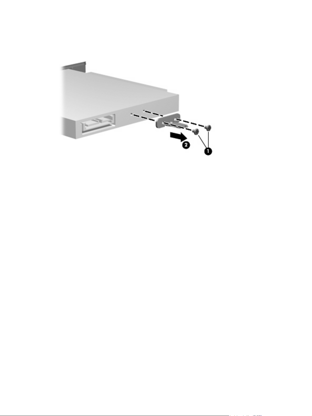
7. Remove the two Phillips PM2.0×3.0 screws (1) that secure the optical drive bracket to the optical
drive.
8. Remove the optical drive bracket (2).
Reverse this procedure to reassemble and install the optical drive.
52 Chapter 4 Removal and replacement procedures
Page 61

Memory module
Description Spare part number
4 GB memory module (DDR2, 800-MHz, PC2-6400, 1-DIMM) 509409-002
2 GB memory module (DDR2, 800-MHz, PC2-6400, 1-DIMM) 509410-002
1 GB memory module (DDR2, 800-MHz, PC2-6400, 1-DIMM) 509411-001
Before removing the memory module, follow these steps:
1. Shut down the computer. If you are unsure whether the computer is off or in Hibernation, turn the
computer on, and then shut it down through the operating system.
2. Disconnect all external devices connected to the computer.
3. Disconnect the power from the computer by first unplugging the power cord from the AC outlet and
then unplugging the AC adapter from the computer.
4. Remove the battery (see
Battery on page 48).
Remove the memory module:
1. Position the computer with the front toward you.
2. Loosen the three Phillips PM2.5×5.5 captive screws (1) that secure the memory module
compartment cover to the computer.
3. Lift the rear edge (2) of the cover, swing it up and to the front, and remove the cover (3). The
memory module compartment cover is included in the Plastics Kit, spare part number
511890-001.
4. Spread the retaining tabs (1) on each side of the memory module slot to release the memory
module. (The edge of the module opposite the slot rises away from the computer.)
Component replacement procedures 53
Page 62

5. Remove the module (2) by pulling it away from the slot at an angle.
NOTE: Memory modules are designed with a notch (3) to prevent incorrect insertion into the
memory module slot.
Reverse this procedure to install a memory module.
54 Chapter 4 Removal and replacement procedures
Page 63
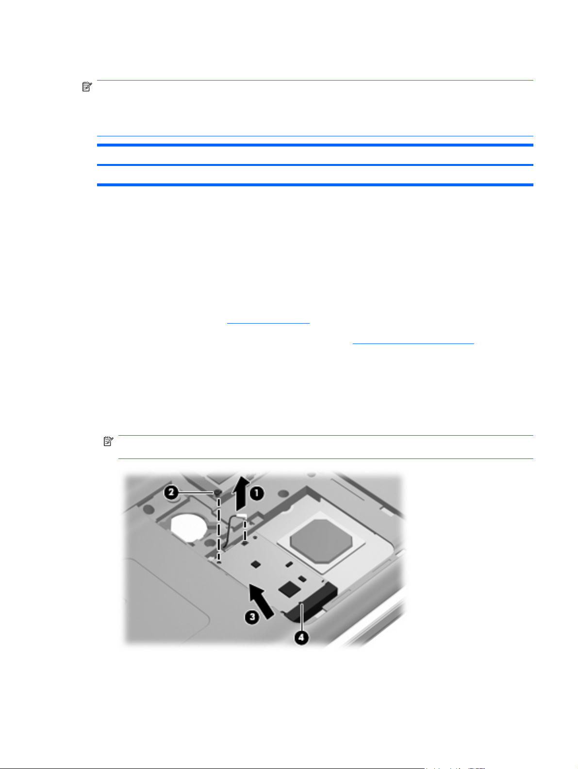
TV tuner module
NOTE: The TV tuner module spare part kit does not include a TV tuner module cable. The TV tuner
module cable is included in the Cable Kit, spare part number 533466-001.
NOTE: The TV tuner external antenna cable with PAL back is available using spare part number
482900-002.
Description Spare part number
DVB-T TV tuner module (for use only with computers equipped with discrete graphics memory) 482899-003
Before removing the TV tuner module, follow these steps:
1. Shut down the computer. If you are unsure whether the computer is off or in Hibernation, turn the
computer on, and then shut it down through the operating system.
2. Disconnect all external devices connected to the computer.
3. Disconnect the power from the computer by first unplugging the power cord from the AC outlet and
then unplugging the AC Adapter from the computer.
4. Remove the battery (see
5. Remove the memory module compartment cover (see
Battery on page 48).
Memory module on page 53).
Remove the TV tuner module:
1. Disconnect the TV tuner module antenna cable (1) from the terminal on the TV tuner module.
2. Remove the Phillips PM2.0×3.0 screw (2) that secures the TV tuner module to the computer.
3. Lift the edge of the TV tuner module (3), and pull the module away from the slot at an angle.
NOTE: The TV tuner module is designed with a notch (4) to prevent incorrect insertion into the
TV tuner module slot.
Reverse this procedure to install the TV tuner module.
Component replacement procedures 55
Page 64

RTC battery
Description Spare part number
RTC battery 449729-001
Before removing the RTC battery, follow these steps:
1. Shut down the computer. If you are unsure whether the computer is off or in Hibernation, turn the
computer on, and then shut it down through the operating system.
2. Disconnect all external devices connected to the computer.
3. Disconnect the power from the computer by first unplugging the power cord from the AC outlet and
then unplugging the AC adapter from the computer.
4. Remove the battery (see
5. Remove the memory module compartment cover (see
Battery on page 48).
Memory module on page 53).
Remove the RTC battery:
Use a non-conductive pointed tool to pry the RTC battery from the socket on the system board.
Reverse this procedure to install the RTC battery. Be sure that the RTC battery is installed with the “+”
sign facing up.
56 Chapter 4 Removal and replacement procedures
Page 65

Hard drive
NOTE: The hard drive spare part kit includes left and right bracket rails, a connector cable, Mylar cover
with tab, and 4 rubber isolators.
Description Spare part number
160-GB, 5400-rpm 537950-001
250-GB, 7200-rpm (select models only) 509412-002
250-GB, 5400-rpm 509414-002
320-GB, 7200-rpm (select models only) 509413-002
320-GB, 5400-rpm 509415-002
500-GB, 5400-rpm 509417-002
Hard Drive Hardware Kit (includes left and right bracket rails, connector cable, Mylar cover with
tab, and 4 rubber isolators)
483862-001
Before removing the hard drive, follow these steps:
1. Shut down the computer. If you are unsure whether the computer is off or in Hibernation, turn the
computer on, and then shut it down through the operating system.
2. Disconnect all external devices connected to the computer.
3. Disconnect the power from the computer by first unplugging the power cord from the AC outlet and
then unplugging the AC adapter from the computer.
4. Remove the battery (see
Battery on page 48).
Remove the hard drive:
1. Position the computer with the front toward you.
2. Loosen the two Phillips PM2.5×5.5 captive screws (1) that secure the hard drive cover to the
computer.
Component replacement procedures 57
Page 66

3. Lift the right side (2) of the hard drive cover, swing it up and to the left, and remove the cover (3).
The hard drive cover is included in the Plastics Kit, spare part number 511890-001.
4. Use the Mylar tab (1) to lift the hard drive up, and then slide it to the left (2) to release it from the
hard drive bay.
5. Disconnect the hard drive adapter cable (3) from the system board.
6. Remove the hard drive from the hard drive bay.
58 Chapter 4 Removal and replacement procedures
Page 67

7. If it is necessary to replace the hard drive bracket or any of the hard drive bracket components,
remove the following:
(1) Hard drive adapter cable
(2) Four rubber isolators
(3) Four Phillips PM3.0×3.5 screws that secure the hard drive bracket rails and Mylar cover to the
hard drive
(4) Left and right hard drive bracket rails with Mylar cover
Reverse this procedure to reassemble and install the hard drive.
Component replacement procedures 59
Page 68

WLAN module
Description Spare part number
Atheros 9285G 802.11b/g WiFi Adapter for use in Canada, the Cayman Islands, Guam, Puerto
Rico, the United States, and the U.S. Virgin Islands
Atheros 9285G 802.11b/g WiFi Adapter for use in Afghanistan, Albania, Algeria, Andorra, Angola,
Antigua and Barbuda, Argentina, Armenia, Aruba, Australia, Austria, Azerbaijan, the Bahamas,
Bahrain, Barbados, Belgium, Belize, Benin, Bermuda, Bhutan, Bosnia and Herzegovina,
Botswana, Brazil, the British Virgin Islands, Brunei, Bulgaria, Burkina Faso, Burundi, Cambodia,
Cameroon, Cape Verde, the Central African Republic, Chad, Chile, Colombia, Comoros, the
Congo, Costa Rica, Croatia, Cyprus, the Czech Republic, Djibouti, Dominica, the Dominican
Republic, East Timor, Ecuador, Egypt, El Salvador, Equatorial Guinea, Eritrea, Estonia, Ethiopia,
Fiji, Finland, France, French Guiana, Gabon, Gambia, Georgia, Germany, Ghana, Gibraltar,
Greece, Grenada, Guadeloupe, Guatemala, Guinea, Guinea-Bissau, Guyana, Haiti, Honduras,
Hong Kong, Hungary, Iceland, India, Indonesia, Ireland, Israel, Italy, the Ivory Coast, Jamaica,
Japan, Jordan, Kazakhstan, Kenya, Kiribati, Kuwait, Kyrgyzstan, Laos, Latvia, Lebanon, Lesotho,
Liberia, Liechtenstein, Lithuania, Luxembourg, Macedonia, Madagascar, Malawi, Malaysia, the
Maldives, Mali, Malta, the Marshall Islands, Martinique, Mauritania, Mauritius, Mexico, Micronesia,
Monaco, Mongolia, Montenegro, Morocco, Mozambique, Namibia, Nauru, Nepal, the Nether
Antilles, the Netherlands, New Zealand, Nicaragua, Niger, Nigeria, Norway, Oman, Palau,
Panama, Papua New Guinea, Paraguay, the People’s Republic of China, Peru, the Philippines,
Poland, Portugal, the Republic of Moldova, Romania, Rwanda, Samoa, San Marino, Sao Tome
and Principe, Saudi Arabia, Senegal, Serbia, the Seychelles, Sierra Leone, Singapore, Slovakia,
Slovenia, the Solomon Islands, Somalia, South Africa, South Korea, Spain, Sri Lanka, St. Kitts
and Nevis, St. Lucia, St. Vincent and the Grenadines, Suriname, Swaziland, Sweden, Switzerland,
Syria, Taiwan, Tajikistan, Tanzania, Togo, Tonga, Trinidad and Tobago, Tunisia, Turkey,
Turkmenistan, Tuvalu, Uganda, the United Arab Emirates, the United Kingdom, Uruguay,
Uzbekistan, Vanuatu, Venezuela, Vietnam, Yemen, Zaire, Zambia, and Zimbabwe
Atheros 9280AGN 802.11a/b/g/n WiFi Adapter for use in Canada, the Cayman Islands, Guam,
Puerto Rico, the United States, and the U.S. Virgin Islands
518436-001
518436-002
518437-001
Atheros 9280AGN 802.11a/b/g/n WiFi Adapter for use in Canada, the Cayman Islands, Guam,
Puerto Rico, the United States, and the U.S. Virgin Islands for use in Afghanistan, Albania, Algeria,
Andorra, Angola, Antigua and Barbuda, Argentina, Armenia, Aruba, Australia, Austria, Azerbaijan,
the Bahamas, Bahrain, Barbados, Belgium, Belize, Benin, Bermuda, Bhutan, Bosnia and
Herzegovina, Botswana, Brazil, the British Virgin Islands, Brunei, Bulgaria, Burkina Faso, Burundi,
Cambodia, Cameroon, Cape Verde, the Central African Republic, Chad, Chile, Colombia,
Comoros, the Congo, Costa Rica, Croatia, Cyprus, the Czech Republic, Djibouti, Dominica, the
Dominican Republic, East Timor, Ecuador, Egypt, El Salvador, Equatorial Guinea, Eritrea, Estonia,
Ethiopia, Fiji, Finland, France, French Guiana, Gabon, Gambia, Georgia, Germany, Ghana,
Gibraltar, Greece, Grenada, Guadeloupe, Guatemala, Guinea, Guinea-Bissau, Guyana, Haiti,
Honduras, Hong Kong, Hungary, Iceland, India, Indonesia, Ireland, Israel, Italy, the Ivory Coast,
Jamaica, Japan, Jordan, Kazakhstan, Kenya, Kiribati, Kuwait, Kyrgyzstan, Laos, Latvia, Lebanon,
Lesotho, Liberia, Liechtenstein, Lithuania, Luxembourg, Macedonia, Madagascar, Malawi,
Malaysia, the Maldives, Mali, Malta, the Marshall Islands, Martinique, Mauritania, Mauritius,
Mexico, Micronesia, Monaco, Mongolia, Montenegro, Morocco, Mozambique, Namibia, Nauru,
Nepal, the Nether Antilles, the Netherlands, New Zealand, Nicaragua, Niger, Nigeria, Norway,
Oman, Palau, Panama, Papua New Guinea, Paraguay, the People’s Republic of China, Peru, the
Philippines, Poland, Portugal, the Republic of Moldova, Romania, Rwanda, Samoa, San Marino,
Sao Tome and Principe, Saudi Arabia, Senegal, Serbia, the Seychelles, Sierra Leone, Singapore,
Slovakia, Slovenia, the Solomon Islands, Somalia, South Africa, South Korea, Spain, Sri Lanka,
St. Kitts and Nevis, St. Lucia, St. Vincent and the Grenadines, Suriname, Swaziland, Sweden,
Switzerland, Syria, Taiwan, Tajikistan, Tanzania, Togo, Tonga, Trinidad and Tobago, Tunisia,
Turkey, Turkmenistan, Tuvalu, Uganda, the United Arab Emirates, the United Kingdom, Uruguay,
Uzbekistan, Vanuatu, Venezuela, Vietnam, Yemen, Zaire, Zambia, and Zimbabwe
Broadcom BCM4312 802.11b/g WLAN module for use only with computers in
Antigua and Barbuda, Barbados, Belize, Canada, the Cayman Islands, Guam, Puerto Rico,
Trinidad and Tobago, the U.S. Virgin Islands, and the United States
518437-002
504593-001
60 Chapter 4 Removal and replacement procedures
Page 69

Description Spare part number
Broadcom BCM4312 802.11b/g WLAN module for use only with computers in Afghanistan,
Albania, Algeria, Andorra, Angola, Antigua and Barbuda, Argentina, Armenia, Aruba, Australia,
Austria, Azerbaijan, the Bahamas, Bahrain, Bangladesh, Barbados, Belarus, Belgium, Belize,
Benin, Bermuda, Bhutan, Bolivia, Bosnia and Herzegovina, Botswana, Brazil,
the British Virgin Islands, Brunei, Bulgaria, Burkina Faso, Burundi, Cameroon, Cape Verde,
the Central African Republic, Chad, Chile, the People's Republic of China, Colombia, Comoros,
the Congo, Costa Rica, Croatia, Cyprus, the Czech Republic, Denmark, Djibouti, Dominica,
the Dominican Republic, East Timor, Ecuador, Egypt, El Salvador, Equitorial Guinea, Eritrea,
Estonia, Ethiopia, Fiji, Finland, France, French Guiana, Gabon, Gambia, Georgia, Germany,
Ghana, Gibraltar, Greece, Grenada, Guadeloupe, Guatemala, Guinea, Guinea-Bissau, Guyana,
Haiti, Honduras, Hong Kong, Hungary, Iceland, India, Ireland, Israel, Italy, the Ivory Coast,
Jamaica, Jordan, Kazakhstan, Kenya, Kiribati, Kyrgyzstan, Laos, Latvia, Lebanon, Lesotho,
Liberia, Liechtenstein, Lithuania, Luxembourg, Macedonia, Madagascar, Malawi, Malaysia,
the Maldives, Mali, Malta, the Marshall Islands, Martinique, Mauritania, Mauritius, Mexico,
Micronesia, Monaco, Mongolia, Montenegro, Morocco, Mozambique, Namibia, Nauru, Nepal,
the Nether Antilles, the Netherlands, New Zealand, Nicaragua, Niger, Nigeria, Norway, Oman,
Pakistan, Palau, Panama, Papua New Guinea, Paraguay, Peru, the Philippines, Poland, Portugal,
the Republic of Moldova, Romania, Russia, Rwanda, Samoa, San Marino, Sao Tome and Principe,
Saudi Arabia, Senegal, Serbia, the Seychelles, Sierra Leone, Singapore, Slovakia, Slovenia,
the Solomon Islands, Somalia, South Africa, South Korea, Spain, Sri Lanka, St. Kitts and Nevis,
St. Lucia, St. Vincent and the Grenadines, Suriname, Swaziland, Sweden, Switzerland, Taiwan,
Tajikistan, Tanzania, Togo, Tonga, Trinidad and Tobago, Tunisia, Turkey, Turkmenistan, Tuvalu,
Uganda, Ukraine, the United Arab Emirates, the United Kingdom, Uruguay, Uzbekistan, Vanuatu,
Venezuela, Vietnam, Yemen, Zaire, Zambia, and Zimbabwe
Broadcom BCM4312 802.11b/g WLAN module for use only with computers in
Antigua and Barbuda, Barbados, Belize, Canada, the Cayman Islands, Guam, Puerto Rico,
Trinidad and Tobago, the U.S. Virgin Islands, and the United States
Broadcom BCM4312 802.11b/g WLAN module for use only with computers in Afghanistan,
Albania, Algeria, Andorra, Angola, Antigua and Barbuda, Argentina, Armenia, Aruba, Australia,
Austria, Azerbaijan, the Bahamas, Bahrain, Bangladesh, Barbados, Belarus, Belgium, Belize,
Benin, Bermuda, Bhutan, Bolivia, Bosnia and Herzegovina, Botswana, Brazil,
the British Virgin Islands, Brunei, Bulgaria, Burkina Faso, Burundi, Cameroon, Cape Verde,
the Central African Republic, Chad, Chile, the People's Republic of China, Colombia, Comoros,
the Congo, Costa Rica, Croatia, Cyprus, the Czech Republic, Denmark, Djibouti, Dominica,
the Dominican Republic, East Timor, Ecuador, Egypt, El Salvador, Equitorial Guinea, Eritrea,
Estonia, Ethiopia, Fiji, Finland, France, French Guiana, Gabon, Gambia, Georgia, Germany,
Ghana, Gibraltar, Greece, Grenada, Guadeloupe, Guatemala, Guinea, Guinea-Bissau, Guyana,
Haiti, Honduras, Hong Kong, Hungary, Iceland, India, Ireland, Israel, Italy, the Ivory Coast,
Jamaica, Jordan, Kazakhstan, Kenya, Kiribati, Kyrgyzstan, Laos, Latvia, Lebanon, Lesotho,
Liberia, Liechtenstein, Lithuania, Luxembourg, Macedonia, Madagascar, Malawi, Malaysia,
the Maldives, Mali, Malta, the Marshall Islands, Martinique, Mauritania, Mauritius, Mexico,
Micronesia, Monaco, Mongolia, Montenegro, Morocco, Mozambique, Namibia, Nauru, Nepal,
the Nether Antilles, the Netherlands, New Zealand, Nicaragua, Niger, Nigeria, Norway, Oman,
Pakistan, Palau, Panama, Papua New Guinea, Paraguay, Peru, the Philippines, Poland, Portugal,
the Republic of Moldova, Romania, Russia, Rwanda, Samoa, San Marino, Sao Tome and Principe,
Saudi Arabia, Senegal, Serbia, the Seychelles, Sierra Leone, Singapore, Slovakia, Slovenia,
the Solomon Islands, Somalia, South Africa, South Korea, Spain, Sri Lanka, St. Kitts and Nevis,
St. Lucia, St. Vincent and the Grenadines, Suriname, Swaziland, Sweden, Switzerland, Taiwan,
Tajikistan, Tanzania, Togo, Tonga, Trinidad and Tobago, Tunisia, Turkey, Turkmenistan, Tuvalu,
Uganda, Ukraine, the United Arab Emirates, the United Kingdom, Uruguay, Uzbekistan, Vanuatu,
Venezuela, Vietnam, Yemen, Zaire, Zambia, and Zimbabwe
504593-002
504664-001
504664-002
Before removing the WLAN module, follow these steps:
1. Shut down the computer. If you are unsure whether the computer is off or in Hibernation, turn the
computer on, and then shut it down through the operating system.
2. Disconnect all external devices connected to the computer.
Component replacement procedures 61
Page 70

3. Disconnect the power from the computer by first unplugging the power cord from the AC outlet and
then unplugging the AC adapter from the computer.
4. Remove the battery (see
5. Remove the hard drive (see
Remove the WLAN module:
CAUTION: To prevent an unresponsive system, replace the wireless module only with a wireless
module authorized for use in the computer by the governmental agency that regulates wireless devices
in your country or region. If you replace the module and then receive a warning message, remove the
module to restore computer functionality, and then contact technical support through Help and Support.
1. Disconnect the WLAN antenna cables (1) from the WLAN module.
NOTE: The black WLAN antenna cable is connected to the WLAN module “Main” terminal. The
white WLAN antenna cable is connected to the WLAN module “Aux” terminal.
2. Remove the Phillips PM2.0×3.0 screw (2) that secures the WLAN module to the computer.
3. Remove the WLAN module (3) by pulling it away from the slot at an angle.
NOTE: WLAN modules are designed with a notch (4) to prevent incorrect insertion into the WLAN
module slot.
Battery on page 48).
Hard drive on page 57).
Reverse this procedure to install a WLAN module.
62 Chapter 4 Removal and replacement procedures
Page 71

Switch cover and keyboard
NOTE: Only select models are equipped with media buttons on the switch cover.
Description Spare part number
Switch cover for use in white computers (includes LED board and cable) 518110-001
Switch cover for use in black computers (includes LED board and cable) 518790-001
Switch cover for use in MTV2 artist edition computers 570205-001
Keyboards Spare part number
White painted keyboard 517864-xxx
White molded keyboard 517863-xxx
Black painted keyboard 518966-xxx
Black molded keyboard 518965-xxx
Black textured keyboard 570228-xxx
NOTE: For a detailed list of available keyboards, see Sequential part number listing on page 31.
Before removing the switch cover and keyboard, follow these steps:
1. Shut down the computer. If you are unsure whether the computer is off or in Hibernation, turn the
computer on, and then shut it down through the operating system.
2. Disconnect all external devices connected to the computer.
3. Disconnect the power from the computer by first unplugging the power cord from the AC outlet and
then unplugging the AC adapter from the computer.
4. Remove the battery (see
Battery on page 48).
Remove the switch cover and keyboard:
1. Position the computer upside down with the front toward you.
Component replacement procedures 63
Page 72

2. Remove the following screws:
(1) Two Phillips PM2.5×6.5 screws that secure the switch cover to the computer
(2) Three Phillips PM2.5×5.0 screws that secure the switch cover to the computer (inside the battery
bay)
(3) Four Phillips PM2.5×6.5 screws that secure the keyboard to the computer
3. Turn the computer display-side up, with the front toward you.
4. Open the computer as far as possible.
5. Lift the rear edge of the switch cover until it detaches from the computer.
64 Chapter 4 Removal and replacement procedures
Page 73

6. Move the switch cover back so it rests on the display.
7. Remove the three Phillips PM2.0×3.0 screws that secure the keyboard to the computer.
8. Lift the rear edge (1) of the keyboard.
9. Slide the keyboard (2) back until the keyboard connector on the system board is accessible.
Component replacement procedures 65
Page 74

10. Release the zero insertion force (ZIF) connector (1) to which the keyboard cable is connected and
disconnect the cable (2) from the system board.
11. Remove the keyboard.
12. Disconnect the power button board cable (1) from the low insertion force (LIF) connector on the
system board.
13. Disconnect the LED board cable (2) from the LIF connector on the system board.
14. Remove the switch cover.
Reverse this procedure to install the switch cover and keyboard.
66 Chapter 4 Removal and replacement procedures
Page 75

Power button board
Description Spare part number
Power button board (includes cable) 512834-001
Before removing the power button board, follow these steps:
1. Shut down the computer. If you are unsure whether the computer is off or in Hibernation, turn the
computer on, and then shut it down through the operating system.
2. Disconnect all external devices connected to the computer.
3. Disconnect the power from the computer by first unplugging the power cord from the AC outlet and
then unplugging the AC Adapter from the computer.
4. Remove the battery (see
5. Remove the switch cover and keyboard (see
Battery on page 48).
Switch cover and keyboard on page 63).
Remove the power button board:
1. Turn the switch cover upside down with the front toward you.
2. Remove the Phillips PM2.5×4.0 screw (1) that secures the power button board to the switch cover.
3. Remove the power button board (2) and cable.
Reverse this procedure to install the power button board.
Component replacement procedures 67
Page 76

Display assembly
NOTE: The display assembly includes a webcam, 2 microphones, and 2 wireless antenna transceivers
and cables.
Description Spare part number
16.0-inch WXGA BrightView display assemblies:
Non-LED for use in white computers 512358-001
Non-LED for use in black computers 512357-001
LED for use in white computers 538349-001
LED for use in black computers 538351-001
LED for use in MTV2 artist edition computers 573304-001
16.0-inch WXGA AntiGlare display assemblies:
Non-LED for use in white computers 538355-001
Non-LED for use in black computers 518771-001
LED assembly for use in white computers 518772-001
LED assembly for use in black computers 538313-001
LED assembly for use in MTV2 artist edition computers 538315-001
15.6-inch WXGA BrightView display assemblies:
Non-LED for use in white computers 518775-001
Non_LED for use in black computers 517862-001
LED for use in white computers 538348-001
LED for use in black computers 538350-001
15.6-inch WXGA AntiGlare display assemblies:
Non LED for use in white computers 518776-001
Non-LED for use in black computers 518777-001
LED for use in white computers 538312-001
LED for use in black computers 538314-001
LED for use in MTV2 artist edition computers 538354-001
Before removing the display assembly, follow these steps:
1. Shut down the computer. If you are unsure whether the computer is off or in Hibernation, turn the
computer on, and then shut it down through the operating system.
2. Disconnect all external devices connected to the computer.
3. Disconnect the power from the computer by first unplugging the power cord from the AC outlet and
then unplugging the AC adapter from the computer.
4. Remove the battery (see
Battery on page 48).
68 Chapter 4 Removal and replacement procedures
Page 77

5. Disconnect the wireless antenna cables from the WLAN module (see WLAN module on page 60).
6. Remove the switch cover and keyboard (see
Switch cover and keyboard on page 63).
Remove the display assembly:
1. Disconnect the display panel cable (1) and the webcam/microphone cable (2) from the system
board.
2. Remove the WLAN antenna cables from the clip (3) built into the top cover.
CAUTION: Support the display assembly when removing the following screws. Failure to support
the display assembly can result in damage to the display assembly and other computer
components.
3. Remove the four Phillips PM2.5×6.5 screws (1) that secure the display assembly to the computer.
Component replacement procedures 69
Page 78

4. Remove the display assembly (2).
NOTE: Steps 5 through 27 provide display assembly internal component removal information for
computers equipped with AntiGlare display assemblies. See steps 28 through 38 for display
assembly internal component removal information for computers equipped with BrightView display
assemblies.
NOTE: See Webcam/microphone moduleon page 49 for webcam/microphone module
replacement instructions for computers equipped with BrightView display assemblies.
5. If it is necessary to replace the display enclosure or any of the display assembly internal
components, remove the following screw covers and screws:
(1) Two plastic screw covers on the display bezel bottom edge. The display plastic screw covers
are included in the Display Rubber Kit, spare part number 513479-001.
(2) Four Phillips PM2.5×7.0 screws.
6. Turn the display assembly upside down, with the bottom edge toward you.
7. Disconnect the display assembly from the display enclosure by prying them apart from one another
along the bottom edge (1).
8. Lift the display enclosure (2) as far as the display logo cable allows.
70 Chapter 4 Removal and replacement procedures
Page 79
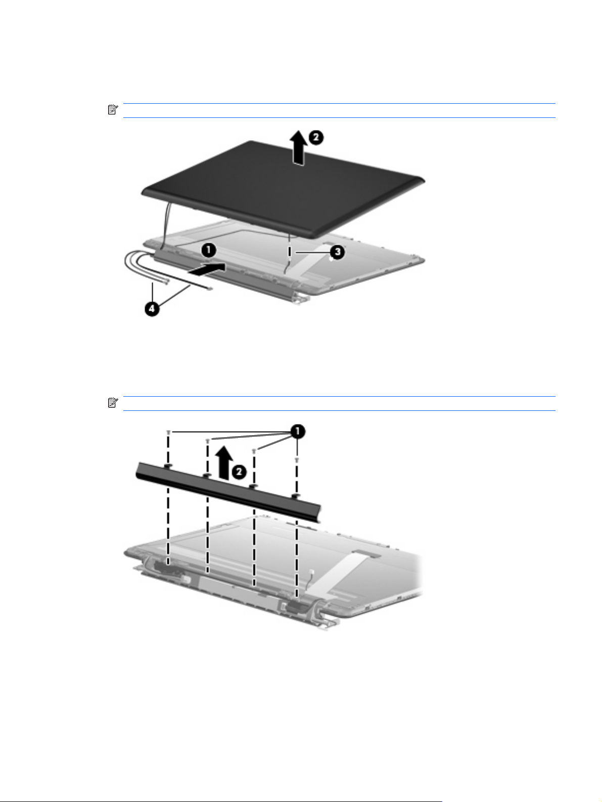
9. Disconnect the display logo cable (3) from the display panel cable.
10. Remove the WLAN antenna cables and the webcam cable (4) from the left hinge.
NOTE: You may have to flex the display hinge cover to remove the WLAN cables.
11. If it is necessary to replace the display inverter, remove the four Phillips PM2.5×5.0 screws (1) that
secure the display inverter cover to the display bezel. The display inverter cover is available using
spare part number 533464-001.
12. Remove the display inverter cover (2) by lifting it straight up.
NOTE: You must remove the display inverter cover to free the antenna cables.
13. Remove the display enclosure. The display enclosure is available using spare part number
517861-001 for white computers, and 518774-001 for black computers, and includes the display
logo LED board and the wireless antenna transceivers and cables.
14. If it is necessary to replace the webcam/microphone module, remove the PM2.0x3.0 screw (1) that
secures the webcam/microphone module to the display.
Component replacement procedures 71
Page 80

15. Slide the webcam/microphone module to the right, and then lift it from the display (2).
16. Disconnect the webcam/microphone module cable (3) from the webcam/microphone module.
17. Remove the webcam/microphone module. The webcam/microphone module is available using
spare part number 512827-001.
18. Disconnect the display inverter from the double-sided tape securing it to the display, and then
release the display inverter (1) as far from the display bezel as the display panel cable and backlight
cable allow.
19. Disconnect the backlight cable (2) and display panel cable (3) from the display inverter.
20. Remove the display inverter. The display inverter is available using spare part number
488317-001.
21. If it is necessary to remove the display panel cable, remove the adhesive reinforcement strip (1)
from the connector, and then disconnect the cable from the connector (2).
22. Remove the tape that secures the display panel cable to the bottom of the display (3).
72 Chapter 4 Removal and replacement procedures
Page 81

23. Remove the cable from the clip on the right display hinge (4).
24. If it is necessary to replace the display hinges, remove the four Phillips PM2.5×5.0 screws (1) that
horizontally secure the display hinge bracket to the display panel.
25. Remove the four Phillips PM2.5×5.0 screws (2) that vertically secure the display hinge bracket to
the display panel.
26. Remove the display hinge bracket (3). The Display Hinge Kit is available using spare part number
513477-001 for computers with 15.6-inch displays and 519209-001 for computers with 16-inch
displays.
Component replacement procedures 73
Page 82

27. If you need to remove the horizontal bracket from the vertical hinge brackets, remove the two
Phillips PM2.0×5.0 screws (1) that connect the brackets together, and then disconnect the
brackets (2).
NOTE: Steps 28 through 38 provide display assembly internal component removal information
for computers equipped with BrightView display assemblies. See steps 5 through 27 for display
assembly internal component removal information for computers equipped with AntiGlare display
assemblies.
NOTE: See Webcam/microphone moduleon page 49 for webcam/microphone module
replacement instructions for computers equipped with BrightView display assemblies.
28. If it is necessary to replace the display bezel or any of the display assembly internal components,
remove the following screw covers and screws:
(1) Two Mylar screw covers on the display bezel bottom edge. The display rubber screw covers
are included in the Display Rubber Kit, spare part number 512361-001.
(2) Two Phillips PM2.5×6.5 screws.
29. Flex the inside edges of the top edge (1), the left and right sides (2), and the bottom edge of the
display bezel (3) until the bezel disengages from the display enclosure.
74 Chapter 4 Removal and replacement procedures
Page 83

30. Remove the display bezel (4). The display bezel is available using spare part number 512359-001
(16-inch display) or 512364-001 (15.6-inch display).
31. If it is necessary to replace the display inverter, disconnect the display inverter from the double-
sided tape securing it to the display, and then release the display inverter (1) as far from the display
enclosure as the display panel cable and backlight cable allow.
32. Disconnect the display panel cable (2) and the backlight cable (3) from the display inverter.
33. Remove the display inverter. The display inverter is available using spare part number
488317-001.
Component replacement procedures 75
Page 84

34. If it is necessary to replace the display panel, remove the two Phillips PM2.5×5.0 screws (1) from
the top corners and the six Phillips PM2.5×5.0 screws (2) from the display hinges.
35. Flex the bottom of the display panel (1) back and release the display hinges. Disconnect the display
LED cable (2) from the display panel cable. Remove the display panel (3). Display panels are
available using spare part numbers 511868-001 (16-inch non-LED display), 570094-001 (16-inch
LED display), 512363-001 (15.6-inch non-LED display), and 570095-001 (15.6-inch LED
display).
36. If it is necessary to replace the display hinges, remove the two Phillips PM2.0×3.0 screws (1) that
secure each display hinge to the display panel.
76 Chapter 4 Removal and replacement procedures
Page 85
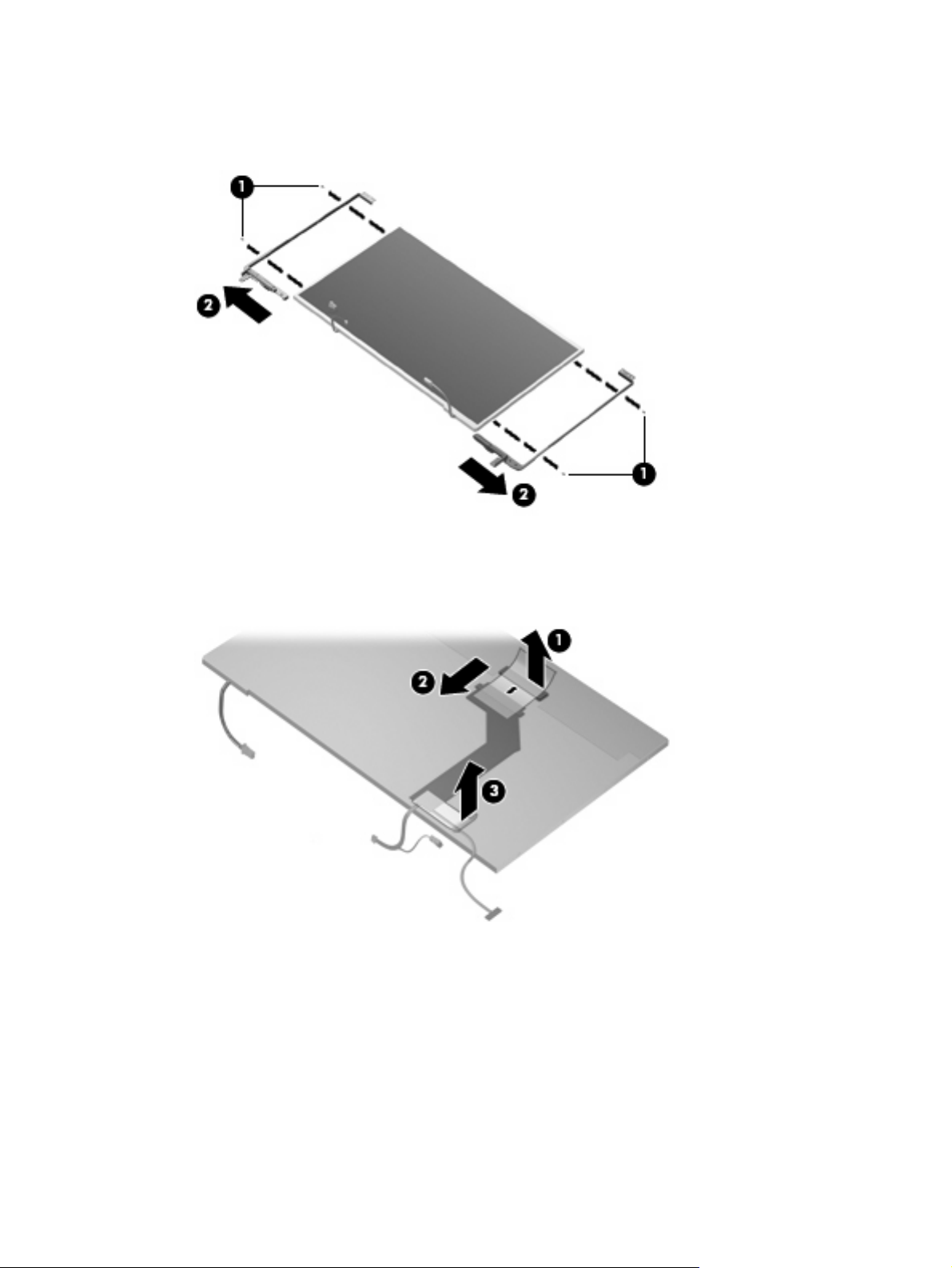
37. Remove the display hinges (2). The display hinges are available in the Display Hinge Bracket Kit,
spare part 512360-001 (16-inch display) or 512365-001 (15.6-inch display). The display hinge
screws are available in the Display Screw Kit, spare part number 512362-001.
38. If it is necessary to remove the display panel cable, remove the adhesive reinforcement strip (1)
from the display panel cable, and disconnect the display panel cable (2). Remove the tape (3) that
secures the cable to the display panel. The display panel cable is available using spare part number
512825-001.
Reverse this procedure to reassemble and install the display assembly.
Component replacement procedures 77
Page 86

Speaker
Before removing the speaker, follow these steps:
1. Shut down the computer. If you are unsure whether the computer is off or in Hibernation, turn the
2. Disconnect all external devices connected to the computer.
3. Disconnect the power from the computer by first unplugging the power cord from the AC outlet and
Description Spare part number
Speaker 533865-001
computer on, and then shut it down through the operating system.
then unplugging the AC adapter from the computer.
4. Remove the battery (see
Battery on page 48).
5. Remove the following components:
a. Hard drive (see
b. Optical drive (see
c. Switch cover and keyboard (see
d. Display assembly (see
Hard drive on page 57)
Optical drive on page 51)
Switch cover and keyboard on page 63)
Display assembly on page 68)
Remove the speaker:
1. Turn the right side up, with the front toward you.
2. Disconnect the speaker cable from the system board (1).
3. Remove the 5 Phillips PM2.5×6.0 screws (2) that secure the speaker to the top cover.
4. Lift the speaker up and off the top cover (3).
Reverse this procedure to install the speaker.
78 Chapter 4 Removal and replacement procedures
Page 87

Bluetooth module
NOTE: The Bluetooth module spare part kit does not include a Bluetooth module cable. The Bluetooth
module cable is available using spare part number 489822-001.
Description Spare part number
Bluetooth module 483113-001
Before removing the Bluetooth module, follow these steps:
1. Shut down the computer. If you are unsure whether the computer is off or in Hibernation, turn the
computer on, and then shut it down through the operating system.
2. Disconnect all external devices connected to the computer.
3. Disconnect the power from the computer by first unplugging the power cord from the AC outlet and
then unplugging the AC Adapter from the computer.
4. Remove the battery (see
5. Remove the switch cover and keyboard (see
Battery on page 48).
Switch cover and keyboard on page 63).
Remove the Bluetooth module:
1. Disconnect the Bluetooth module cable (1) from the system board.
2. Remove the Phillips PM2.0×3.0 screw (2) that secures the Bluetooth module to the top cover.
3. Remove the Bluetooth module from the top cover (3).
4. Remove the Bluetooth module.
Reverse this procedure to install the Bluetooth module.
Component replacement procedures 79
Page 88

Top cover
Description Spare part number
For use only with white computers equipped with a fingerprint reader 518109-001
For use only with white computers not equipped with a fingerprint reader 518108-001
For use only with black computers equipped with a fingerprint reader 518789-001
For use only with black computers not equipped with a fingerprint reader 518788-001
For use only with MTV2 artist edition computers 570206-001
Before removing the top cover, follow these steps:
1. Shut down the computer. If you are unsure whether the computer is off or in Hibernation, turn the
2. Disconnect all external devices connected to the computer.
3. Disconnect the power from the computer by first unplugging the power cord from the AC outlet and
computer on, and then shut it down through the operating system.
then unplugging the AC adapter from the computer.
4. Remove the battery (see
Battery on page 48).
5. Remove the following components:
a. Hard drive (see
b. Optical drive (see
c. Switch cover and keyboard (see
d. Display assembly (see
Hard drive on page 57)
Optical drive on page 51)
Switch cover and keyboard on page 63)
Display assembly on page 68)
Remove the top cover:
1. Turn the computer upside down, with the front toward you.
2. Remove the 10 Phillips PM2.5×7.0 screws (1) that secure the top cover to the computer.
80 Chapter 4 Removal and replacement procedures
Page 89

3. Remove the Phillips PM2.5×4.0 screw (2) that secures the top cover to the computer. This screw
is in the battery bay.
4. Turn the computer right-side up, with the front toward you.
5. Disconnect the following cables from the system board:
(1) TouchPad cable
(2) Fingerprint reader board cable
NOTE: This cable connects to a LIF connector on the system board.
Component replacement procedures 81
Page 90

6. Remove the four Phillips PM2.5×4.0 screws that secure the top cover to the computer.
7. Lift the rear edge (1) of the top cover until it rests at an angle.
8. Remove the top cover (2) by lifting it straight up.
Reverse this procedure to install the top cover.
82 Chapter 4 Removal and replacement procedures
Page 91

Modem module
NOTE: The modem module spare part kit does not include a modem module cable. The modem
module cable is included in the Cable Kit, spare part number 533466-001. See
for more Cable Kit spare part number information.
Description Spare part number
Modem module for use in all countries and regions except Australia and New Zealand 510100-001
Modem module for use only in Australia and New Zealand 510100-011
Before removing the modem module, follow these steps:
1. Shut down the computer. If you are unsure whether the computer is off or in Hibernation, turn the
computer on, and then shut it down through the operating system.
2. Disconnect all external devices connected to the computer.
3. Disconnect the power from the computer by first unplugging the power cord from the AC outlet and
then unplugging the AC Adapter from the computer.
Cable Kit on page 29
4. Remove the battery (see
Battery on page 48).
5. Remove the following components:
a. Hard drive (see
b. Optical drive (see
c. Switch cover and keyboard (see
d. Display assembly (see
e. Top cover (see
Hard drive on page 57).
Optical drive on page 51).
Switch cover and keyboard on page 63).
Display assembly on page 68).
Top cover on page 80).
Remove the modem module:
1. Disconnect the modem module cable (1) from the modem module.
2. Remove the two Phillips PM2.5×3.0 screws (2) that secure the modem module to the system board.
Component replacement procedures 83
Page 92

3. Lift the modem module (3) straight up to disconnect it from the system board.
Reverse this procedure to install the modem module.
Audio/infrared board
Description Spare part number
Audio/infrared board for use with computers equipped with discrete graphics memory (includes
cable)
Audio/infrared board for use with computers equipped with UMA graphics memory (includes cable) 511892-001
512836-001
Before removing the audio/infrared board, follow these steps:
1. Shut down the computer. If you are unsure whether the computer is off or in Hibernation, turn the
computer on, and then shut it down through the operating system.
2. Disconnect all external devices connected to the computer.
3. Disconnect the power from the computer by first unplugging the power cord from the AC outlet and
then unplugging the AC Adapter from the computer.
4. Remove the battery (see
Battery on page 48).
5. Remove the following components:
a. Hard drive (see
b. Optical drive (see
c. Switch cover and keyboard (see
d. Display assembly (see
Hard drive on page 57).
Optical drive on page 51).
Switch cover and keyboard on page 63).
Display assembly on page 68).
e. Top cover (see
Top cover on page 80).
84 Chapter 4 Removal and replacement procedures
Page 93

Remove the audio/infrared board:
1. Disconnect the audio/infrared board cable (1) from the LIF connector on the system board.
2. Remove the Phillips PM2.5x7.0 screw (2) that secures the audio/infrared board to the base
enclosure.
3. Release the clip (3) built into the base enclosure that secures the audio/infrared board.
4. Lift the audio/infrared board (4) straight up to remove it from the base enclosure.
Reverse this procedure to install the audio/infrared board.
USB board
Description Spare part number
USB board (includes cable) 516497-001
Before removing the USB board, follow these steps:
1. Shut down the computer. If you are unsure whether the computer is off or in Hibernation, turn the
2. Disconnect all external devices connected to the computer.
3. Disconnect the power from the computer by first unplugging the power cord from the AC outlet and
4. Remove the battery (see
5. Remove the following components:
computer on, and then shut it down through the operating system.
then unplugging the AC Adapter from the computer.
Battery on page 48).
a. Hard drive (see
b. Optical drive (see
Hard drive on page 57).
Optical drive on page 51).
c. Switch cover and keyboard (see
Switch cover and keyboard on page 63).
Component replacement procedures 85
Page 94

d. Display assembly (see Display assembly on page 68).
e. Top cover (see
Top cover on page 80).
Remove the USB board:
1. Disconnect the USB board cable (1) from the LIF connector on the system board.
2. Remove the Phillips PM2.5×7.0 screw (2) that secures the USB board to the base enclosure.
3. Remove the USB board (3) from the base enclosure.
Reverse this procedure to install the USB board.
Power connector cable
Description Spare part number
Power connector cable 533465-001
Before removing the power connector cable, follow these steps:
1. Shut down the computer. If you are unsure whether the computer is off or in Hibernation, turn the
computer on, and then shut it down through the operating system.
2. Disconnect all external devices connected to the computer.
3. Disconnect the power from the computer by first unplugging the power cord from the AC outlet and
then unplugging the AC Adapter from the computer.
4. Remove the battery (see
5. Remove the following components:
a. Hard drive (see
b. Optical drive (see
Battery on page 48).
Hard drive on page 57).
Optical drive on page 51).
c. Switch cover and keyboard (see
Switch cover and keyboard on page 63).
86 Chapter 4 Removal and replacement procedures
Page 95

d. Display assembly (see Display assembly on page 68).
e. Top cover (see
f. USB board (see
g. System board (see
Top cover on page 80).
USB board on page 85).
System board on page 88).
Remove the power connector cable:
1. Remove the power connector cable (1) from the clips and routing channel (2) built into the base
enclosure.
2. Remove the Phillips PM2.5×7.0 screw (3) that secures the power connector and bracket to the
base enclosure.
3. Remove the power connector bracket (4).
4. Remove the power connector cable assembly (5).
Reverse this procedure to install the power connector cable.
Component replacement procedures 87
Page 96

System board
NOTE: The system board spare kit includes replacement thermal material.
Description Spare part number
For use with computers equipped with discrete graphics subsystem memory and 1 GB of dedicated
memory
For use with computers equipped with discrete graphics subsystem memory and 512 MB of
dedicated memory
For use with computers equipped with UMA graphics subsystem memory 509449-001
For use with computers equipped with SidePort memory 570379-001
509450-001
509451-001
Before removing the system board, follow these steps:
1. Shut down the computer. If you are unsure whether the computer is off or in Hibernation, turn the
computer on, and then shut it down through the operating system.
2. Disconnect all external devices connected to the computer.
3. Disconnect the power from the computer by first unplugging the power cord from the AC outlet and
then unplugging the AC adapter from the computer.
4. Remove the battery (see
Battery on page 48).
5. Remove the following components:
a. Hard drive (see
b. Optical drive (see
Hard drive on page 57)
Optical drive on page 51)
c. Switch cover (see
d. Display assembly (see
e. Top cover (see
Switch cover and keyboard on page 63)
Display assembly on page 68)
Top cover on page 80)
When replacing the system board, be sure that the following components are removed from the defective
system board and installed on the replacement system board:
TV tuner module (see
●
RTC battery (see
●
Memory module (see
●
Bluetooth module (see
●
WLAN module (see
●
Modem module (see
●
Processor (see
●
TV tuner module on page 55)
RTC battery on page 56)
Memory module on page 53)
Bluetooth module on page 79)
WLAN module on page 60)
Modem module on page 83)
Processor on page 96)
Remove the system board:
1. Disconnect the modem module cable (1) from the modem module.
88 Chapter 4 Removal and replacement procedures
Page 97

2. Disconnect the following cables from the system board:
(2) Audio/infrared board cable
NOTE: The audio/infrared board cable connects to a LIF connector on the system board.
(3) USB board cable
NOTE: The USB board cable connects to a LIF connector on the system board.
(4) Power connector cable
3. Remove the Phillips PM2.5×7.0 screw (1) that secures the system board to the base enclosure.
4. Lift the right side (2) of the system board until it rests at an angle.
5. Remove the system board (3) by sliding it up and to the right at an angle.
Reverse this procedure to install the system board.
Component replacement procedures 89
Page 98

TV tuner module cable
NOTE: The TV tuner module cable is available in the Cable Kit, spare part number 533466-001.
Before removing the TV tuner module cable, follow these steps:
1. Shut down the computer. If you are unsure whether the computer is off or in Hibernation, turn the
computer on, and then shut it down through the operating system.
2. Disconnect all external devices connected to the computer.
3. Disconnect the power from the computer by first unplugging the power cord from the AC outlet and
then unplugging the AC Adapter from the computer.
4. Remove the battery (see
5. Remove the following components:
a. Hard drive (see
b. Optical drive (see
c. Switch cover and keyboard (see
d. Display assembly (see
e. Top cover (see
f. USB board (see
g. System board (see
Remove the TV tuner module cable:
1. Remove the TV tuner antenna connector from the clips (1) built into the base enclosure.
2. Remove the TV tuner module cable (2) from the clips and routing channel (3) built into the base
enclosure.
Battery on page 48).
Hard drive on page 57).
Optical drive on page 51).
Switch cover and keyboard on page 63).
Display assembly on page 68).
Top cover on page 80).
USB board on page 85).
System board on page 88).
Reverse this procedure to install the TV tuner module cable.
90 Chapter 4 Removal and replacement procedures
Page 99

Modem module cable
NOTE: The modem module cable is available in the Cable Kit, spare part number 533466-001. The
modem module cable includes the RJ-11 jack.
Before removing the modem module cable, follow these steps:
1. Shut down the computer. If you are unsure whether the computer is off or in Hibernation, turn the
computer on, and then shut it down through the operating system.
2. Disconnect all external devices connected to the computer.
3. Disconnect the power from the computer by first unplugging the power cord from the AC outlet and
then unplugging the AC Adapter from the computer.
4. Remove the battery (see
5. Remove the following components:
a. Hard drive (see
b. Optical drive (see
c. Switch cover and keyboard (see
d. Display assembly (see
e. Top cover (see
f. USB board (see
g. System board (see
Remove the modem module cable:
1. Remove the RJ-11 jack from the clips (1) built into the base enclosure.
2. Remove the modem module cable (2) from the clips and routing channel (3) built into the base
enclosure.
Battery on page 48).
Hard drive on page 57).
Optical drive on page 51).
Switch cover and keyboard on page 63).
Display assembly on page 68).
Top cover on page 80).
USB board on page 85).
System board on page 88).
Reverse this procedure to install the modem module cable.
Component replacement procedures 91
Page 100

Fan/heat sink assembly
NOTE: The fan/heat sink assembly spare kit includes replacement thermal material.
Description Spare part number
For use only with computers equipped with graphics subsystems with discrete memory 532141-001
For use only with computers equipped with graphics subsystems with UMA memory 532142-001
NOTE: To properly ventilate the computer, allow at least a 7.6-cm (3-inch) clearance on the right side
and rear panel of the computer. The computer uses an electric fan for ventilation. The fan is controlled
by a temperature sensor and is designed to turn on automatically when high temperature conditions
exist. These conditions are affected by high external temperatures, system power consumption, power
management/battery conservation configurations, battery fast charging, and software requirements.
Exhaust air is displaced through the ventilation grill located on the left side of the computer.
Before removing the fan/heat sink assembly, follow these steps:
1. Shut down the computer. If you are unsure whether the computer is off or in Hibernation, turn the
computer on, and then shut it down through the operating system.
2. Disconnect all external devices connected to the computer.
3. Disconnect the power from the computer by first unplugging the power cord from the AC outlet and
then unplugging the AC adapter from the computer.
4. Remove the battery (see
Battery on page 48).
5. Remove the following components:
a. Hard drive (see
b. Optical drive (see
c. Switch cover and keyboard (see
d. Display assembly (see
e. Top cover (see
f. USB board (see
g. System board (see
Hard drive on page 57).
Optical drive on page 51).
Switch cover and keyboard on page 63).
Display assembly on page 68).
Top cover on page 80).
USB board on page 85).
System board on page 88).
Remove the fan/heat sink assembly:
NOTE: Steps 1 through 5 apply only to models with discrete subsystem memory on the system board.
Steps 6 through 10 apply only to models with UMA subsystem memory on the system board.
1. Turn the system board upside down, with the expansion port 3 and external monitor port toward
you.
2. Disconnect the fan cable (1) from the system board.
3. Loosen the three Phillips PM2.5×14.0 spring-loaded, captive screws (2), (3), and (4) that secure
the fan/heat sink assembly to the system board.
92 Chapter 4 Removal and replacement procedures
 Loading...