

Page 1

HPE D6020 Disk Enclosure User
Guide
Abstract
This guide provides component information, as well as instructions on the operation, setup, and configuration of the HPE D6020
Disk Enclosure. Troubleshooting and product specifications are also included. This guide is intended for use by experienced
service technicians. HPE assumes that you are qualified in servicing this equipment, trained in recognizing product hazards,
and are familiar with weight and stability precautions.
Part Number: 839756-001
Published: June 2016
Edition: First
Page 2

© Copyright 2016 Hewlett Packard Enterprise Development LP
The information contained herein is subject to change without notice. The only warranties for Hewlett Packard Enterprise products and services
are set forth in the express warranty statements accompanying such products and services. Nothing herein should be construed as constituting
an additional warranty. Hewlett Packard Enterprise shall not be liable for technical or editorial errors or omissions contained herein.
Confidential computer software. Valid license from Hewlett Packard Enterprise required for possession, use, or copying. Consistent with FAR
12.211 and 12.212, Commercial Computer Software, Computer Software Documentation, and Technical Data for Commercial Items are licensed
to the U.S. Government under vendor's standard commercial license.
Links to third-party websites take you outside the Hewlett Packard Enterprise website. Hewlett Packard Enterprise has no control over and is not
responsible for information outside the Hewlett Packard Enterprise website.
Acknowledgments
Intel®, Itanium®, Pentium®, Intel Inside®, and the Intel Inside logo are trademarks of Intel Corporation in the United States and other countries.
Microsoft® and Windows® are trademarks of the Microsoft group of companies.
Adobe® and Acrobat® are trademarks of Adobe Systems Incorporated.
Java and Oracle are registered trademarks of Oracle and/or its affiliates.
UNIX® is a registered trademark of The Open Group.
Revision History
June 2016Revision 839756-001
Includes HPE D6020 Disk Enclosure details for the first edition.
Page 3

Contents
1 Component identification.....................................................................................5
Understanding front panel components................................................................................................5
Understanding front panel LEDs and buttons.......................................................................................5
Understanding rear panel components.................................................................................................7
Understanding rear panel LEDs and buttons.......................................................................................8
Understanding device bay ID numbers.................................................................................................9
Understanding hard drive LEDs..........................................................................................................10
Understanding hard drive LED combinations.....................................................................................10
2 Setting up the system........................................................................................12
Space and airflow requirements.........................................................................................................12
Temperature requirements..................................................................................................................12
Power requirements............................................................................................................................13
Grounding requirements.....................................................................................................................13
Rack warnings....................................................................................................................................14
Third-party racks.................................................................................................................................14
Site planning considerations...............................................................................................................14
Installing the chassis in the rack.........................................................................................................14
Installing hard drives...........................................................................................................................16
Installing the I/O module.....................................................................................................................19
Cabling................................................................................................................................................20
Installing mini-SAS I/O cables.......................................................................................................20
Cabling the system........................................................................................................................20
Selecting and connecting the power cord...........................................................................................24
Selecting an approved power cord................................................................................................24
Connecting the power cord............................................................................................................24
3 Operating the system........................................................................................25
Identifying, using, and installing firmware updates.............................................................................25
Powering up and powering down the D6020......................................................................................25
Powering up...................................................................................................................................25
Powering down..............................................................................................................................25
4 Configuring the system and using available utilities..........................................27
Using configuration tools....................................................................................................................27
HPE Smart Storage Administrator Diagnostics Utility...................................................................27
Smart Components for ROM Flash...............................................................................................27
Using management tools....................................................................................................................27
HPE Systems Insight Manager......................................................................................................27
Management Agents.....................................................................................................................27
Using diagnostic tools.........................................................................................................................28
Integrated Management Log.........................................................................................................28
Keeping the system current................................................................................................................28
Change control and proactive notification.....................................................................................28
Care Pack......................................................................................................................................28
5 Troubleshooting the system..............................................................................29
If the D6020 does not power up..........................................................................................................29
LED behavior......................................................................................................................................30
7-segment display status codes and actions.................................................................................31
Recognizing hard drive failure............................................................................................................34
Understanding the effects of a hard drive failure...........................................................................35
Identifying a compromised fault tolerance.....................................................................................35
Recovering from compromised fault tolerance..............................................................................35
Contents 3
Page 4

Factors to consider before replacing hard drives...............................................................................35
Automatic data recovery (rebuild).......................................................................................................36
Time required for a rebuild............................................................................................................36
Failure of another drive during rebuild...........................................................................................37
Recovering from a power failure reported from the backplane.....................................................37
6 Support and other resources.............................................................................38
Accessing Hewlett Packard Enterprise Support.................................................................................38
Accessing updates..............................................................................................................................38
Websites.............................................................................................................................................39
Customer self repair...........................................................................................................................39
Remote support..................................................................................................................................39
Documentation feedback....................................................................................................................39
A Electrostatic discharge......................................................................................40
Preventing electrostatic discharge......................................................................................................40
Grounding methods to prevent electrostatic discharge......................................................................40
B Specifications....................................................................................................41
Environmental specifications..............................................................................................................41
D6020 Chassis specifications.............................................................................................................41
C Warranty and regulatory information.................................................................42
Warranty information...........................................................................................................................42
Regulatory information........................................................................................................................42
Belarus Kazakhstan Russia marking.............................................................................................42
Turkey RoHS material content declaration....................................................................................43
Ukraine RoHS material content declaration..................................................................................43
Glossary...............................................................................................................44
4 Contents
Page 5
1 Component identification
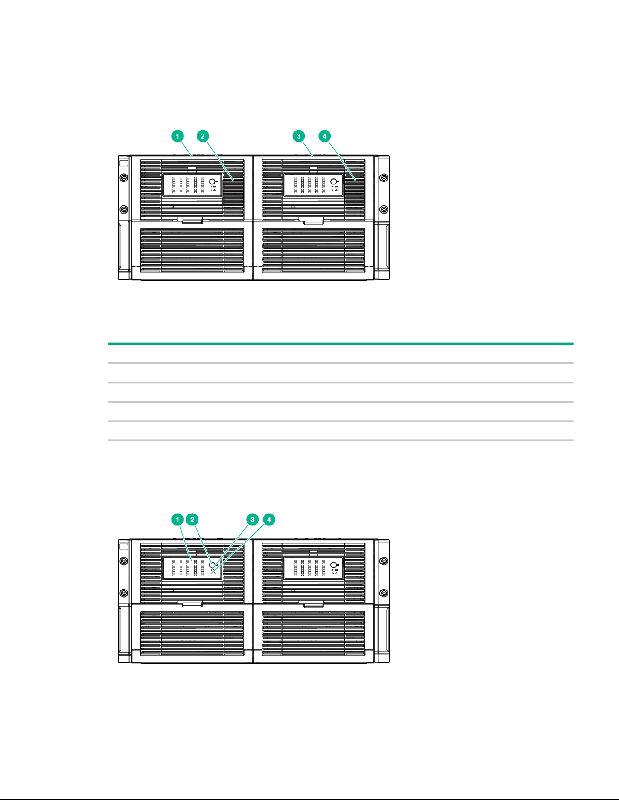
Understanding front panel components
Figure 1 Front panel components
Table 1 Front panel component descriptions
DescriptionItem
Drawer 11
Drawer 1 diagnostic cable access (For use by authorized HPE personnel only)2
Drawer 23
Drawer 2 diagnostic cable access (For use by authorized HPE personnel only)4
Understanding front panel LEDs and buttons
Figure 2 Front panel LEDs and buttons
Understanding front panel components 5
Page 6

Table 2 Front panel LED and button descriptions
StatusDescriptionItem
Green = The drive is online, but it is not currently
active.
Hard drive LEDs
Normal mode (UID LED is off)
1
Flashing irregularly green = The drive is active and
operating normally.
Flashing green (1 Hz) = The drive is rebuilding, or
it is part of an array that is undergoing expansion,
logical drive extension, a stripe size migration, or
RAID migration.
CAUTION: Do not remove the drive. Removing
the drive may terminate the current operation and
cause data loss.
Flashing amber/green = The drive is configured and
indicating a predictive failure. The drive may also
be undergoing a rebuild, expansion, extension, or
migration.
Flashing amber (1 Hz) = A predictive failure alert
has been received for this drive. Replace the drive
as soon as possible.
Amber = A drive failure, link failure, or mismatched
configuration has occurred.
Off = The drive is offline, a spare, or not configured
as part of an array.
Green = The drive is selected by a management
application and operating normally.
Hard drive LEDs
Drive Locate mode (UID LED is solid)
Flashing amber (1 Hz) = The drive is not selected
and is indicating a predictive failure.
Flashing amber/green = The drive has been
selected by a management application and is
indicating a predictive failure.
Amber = The drive might or might not be selected
and is indicating drive failure, link failure, or
mismatched configuration.
Blue = The drive is in Locate mode/Safe to remove.
Flashing Blue = The drive is in Locate mode/Do not
remove.
Off = The drive is not selected.
Blue = The drive is in Locate mode. The UID LED
is enabled from the UID button
UID button/LED2
Off = The UID LED is disabled.
Green = The system health is good.Internal Health LED3
Off = The system is off.
Amber = The enclosure requires a service check.
Check the I/O module, fan and power supply LEDs,
and AC power cables to power supplies.
GSI LED4
Off = The enclosure is functioning normally.
6 Component identification
Page 7
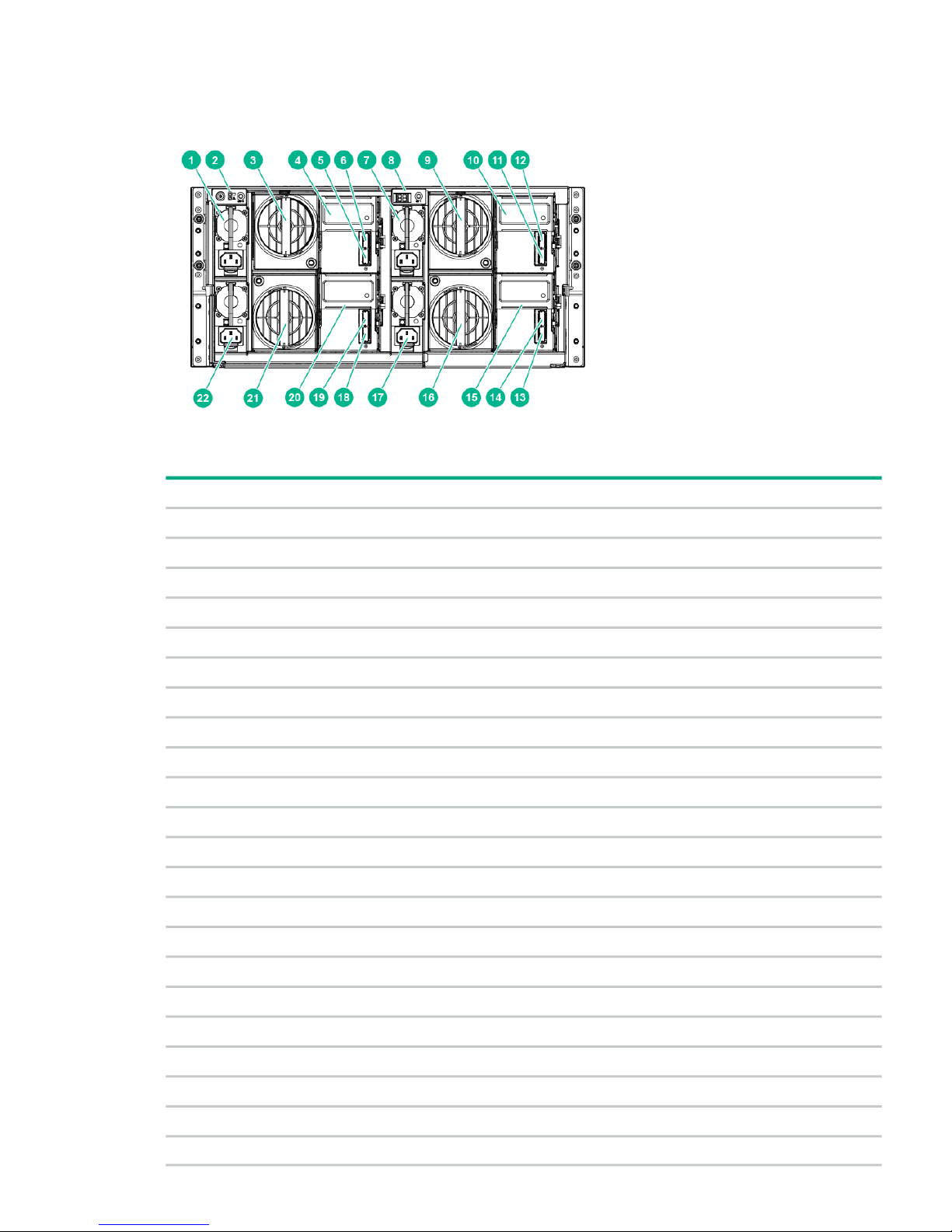
Understanding rear panel components
Figure 3 Rear panel components
Table 3 Rear panel component descriptions
DescriptionItem
Power supply 11
Power On/UID 2 status panel2
Fan module 1 (Drawer 2)3
Primary I/O module (Drawer 2)4
SAS port 1 connector (Drawer 2)5
SAS port 2 connector (Drawer 2)6
Power supply 37
UID 1 status panel8
Fan module 1 (Drawer 1)9
Primary I/O module (Drawer 1)10
SAS port 1 connector (Drawer 1)11
SAS port 2 connector (Drawer 1)12
SAS port 1 connector (Drawer 1)13
SAS port 2 connector (Drawer 1)14
Secondary I/O module (Drawer 1)15
Fan module 2 (Drawer 1)16
Power supply 417
SAS port 1 connector (Drawer 2)18
SAS port 2 connector (Drawer 2)19
Secondary I/O module (Drawer 2)20
Fan module 2 (Drawer 2)21
Power supply 222
Understanding rear panel components 7
Page 8
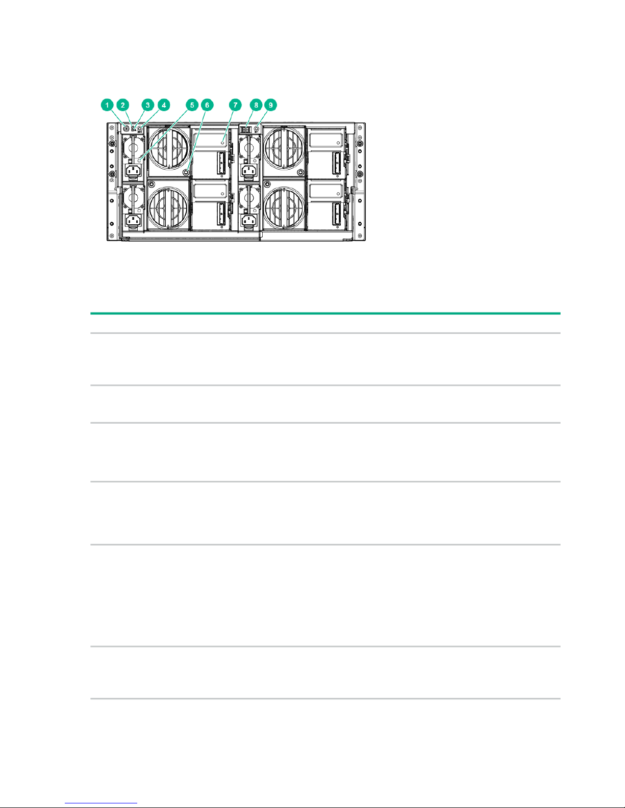
Understanding rear panel LEDs and buttons
Figure 4 Rear panel LEDs and buttons
Table 4 Rear panel LED and button descriptions
StatusDescriptionItem
Green = OnPower On/Standby button and
system power LED
1
Amber = Standby (auxiliary power present)
Off = Off
Green = System health is good.Internal Health LED2
Off = System is off.
Amber = Enclosure requires a service check. Check the I/O
module, fan and power supply LEDs, and AC power cables to
power supplies.
GSI LED
1
3
Off = Enclosure is functioning normally.
Blue = UID LED is enabled from the UID button.UID button/LED (Drawer 2)4
Blue solid = System is in hard drive Locate mode or an enclosure
firmware update is in progress.
Off = UID LED is disabled.
Green = Power on and power supply functioning properlyPower supply LED5
Off = One or more of the following conditions exists:
• System powered off
• AC power unavailable
• Power supply failed
• Power supply exceeded current limit
Green = Normal operationSystem fan LED6
Amber flashing = Fault
Off = Fan unseated from connector or failed
8 Component identification
Page 9

Table 4 Rear panel LED and button descriptions (continued)
StatusDescriptionItem
I/O module LED7
Definition (Locate/Safe to
Remove Behavior)
LED Status
AmberGreenBlue
No power.OffOffOff
Healthy.OffOnOff
Faulty.OnOffBlink
Locate mode/Do not remove.
Faulty.OnOffOn
Locate mode/Safe to remove.
Healthy.OffOnOn or
Blink
Manual locate/Safe to remove.
Refer to Table 8 (page 31) for more information7-segment display8
Blue = UID LED is enabled from the UID button.UID button/LED (Drawer 1)9
Blue solid = System is in hard drive Locate mode, or an enclosure
firmware update is in progress.
Off = UID LED is disabled.
1
If the GSI is amber, the system needs service. Activate the associated drawer UID button to view any GSI error codes
on the rear display.
Understanding device bay ID numbers
Figure 5 Device bay ID numbers
Understanding device bay ID numbers 9
Page 10
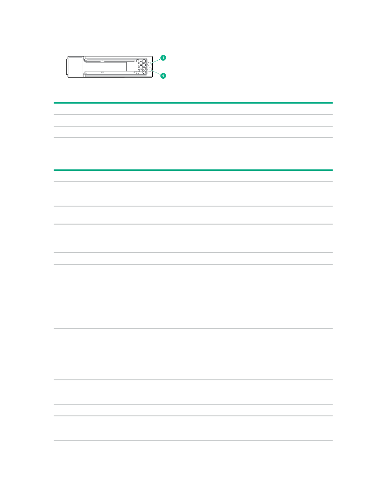
Understanding hard drive LEDs
Figure 6 Hard drive LEDs
Table 5 Hard drive LED descriptions
DescriptionItem
Fault/UID LED (amber/blue)1
Online LED (green)2
Understanding hard drive LED combinations
Table 6 Hard drive LED combination interpretations
InterpretationFault/UID LED (amber/blue)Online/activity LED (green)
The drive has failed, or a predictive failure alert has
been received for this drive; it also has been selected
by a management application.
Alternating amber and blueOn, off, or flashing
The drive is operating normally, and it has been
selected by a management application.
Steadily blueOn, off, or flashing
A predictive failure alert has been received for this
drive.
Amber, flashing regularly (1 Hz)On
Replace the drive as soon as possible.
The drive is online, but it is not currently active.OffOn
CAUTION: Do not remove the drive. Removing a
drive may terminate the current operation and cause
data loss.
Amber, flashing regularly (1 Hz)Flashing regularly (1 Hz)
The drive is part of an array that is undergoing
capacity expansion or a stripe size migration, but a
predictive failure alert has been received for this
drive. To minimize the risk of data loss, do not replace
the drive until the expansion or migration is complete.
CAUTION: Do not remove the drive. Removing a
drive may terminate the current operation and cause
data loss.
OffFlashing regularly (1 Hz)
The drive is rebuilding, or it is part of an array that is
undergoing array expansion, logical drive extension,
a stripe size migration, or RAID migration.
The drive is active, but a predictive failure alert has
been received for this drive. Replace the drive as
soon as possible.
Amber, flashing regularly (1 Hz)Flashing irregularly
The drive is active and operating normally.OffFlashing irregularly
A critical fault condition has been identified for this
drive, and the controller has placed it offline. Replace
the drive as soon as possible.
Steadily amberOff
10 Component identification
Page 11

Table 6 Hard drive LED combination interpretations (continued)
InterpretationFault/UID LED (amber/blue)Online/activity LED (green)
A predictive failure alert has been received for this
drive. Replace the drive as soon as possible.
Amber, flashing regularly (1 Hz)Off
The drive is offline, a spare, or not configured as part
of an array.
OffOff
Understanding hard drive LED combinations 11
Page 12
2 Setting up the system
Space and airflow requirements
To enable servicing and ensure adequate airflow, observe the following spatial requirements
when deciding where to install a rack:
• Leave a minimum clearance of 63.5 cm (25.0 in) in front of the rack.
• Leave a minimum clearance of 76.2 cm (30.0 in) in back of the rack.
• Leave a minimum clearance of 121.9 cm (48.0 in) from the back of the rack to the rear of
another rack or row of racks.
• Ensure that at least 30 cm (11.81 in) of open space is available to the right of the right hard
drive drawer to facilitate the installation and removal of hard drives.
The D6020 draws in cool air through the front door, and then expels warm air through the rear
door. Therefore, the front and rear rack doors must be ventilated adequately to enable ambient
room air to enter the cabinet, and the rear door must be ventilated adequately to enable the warm
air to escape from the cabinet.
CAUTION: To prevent improper cooling and damage to the equipment, do not block the
ventilation openings.
CAUTION: If a vertical space in the rack is not populated by a node (server) or rack component,
the gaps between the components cause changes in airflow through the rack and across the
nodes. Cover all gaps with blanking panels to maintain proper airflow. This arrangement ensures
proper airflow. Using a rack without blanking panels results in improper cooling that can lead to
thermal damage.
The HPE Rack 10000 series rack provides proper node cooling from flow-through perforations
in the front and rear doors that provide a 64 percent open area for ventilation.
CAUTION: HPE has not tested or validated the D6020 with third-party racks. If a third-party
rack is used, observe the following additional requirements to ensure adequate airflow and to
prevent damage to the equipment:
• Front and rear doors—If the 42U rack includes closing front and rear doors, you must allow
at least 5,350 sq cm (830 sq in) of holes evenly distributed from top to bottom to permit
adequate airflow (equivalent to the required 64 percent open area for ventilation).
• Side—The clearance between the installed rack component and the side panels of the rack
must be a minimum of 7 cm (2.75 in).
Temperature requirements
To ensure continued safe and reliable equipment operation, install or position the rack in a
well-ventilated, climate-controlled environment.
The maximum TMRA for most storage products is 35°C (95°F). The temperature in the cold aisle
where the rack is located must not exceed 35°C (95°F). The D6020 reports an over-temperature
condition and performs an emergency shutdown of the hard drive bays within a drawer if the
12 Setting up the system
Page 13
temperature exceeds this limit for greater than 3 minutes. To recover the system, AC power cycle
the D6020.
CAUTION: To reduce the risk of damage to the equipment when installing third-party options:
• Do not permit optional equipment to impede airflow around the chassis or to increase the
internal rack temperature beyond the maximum allowable limits.
• Do not exceed the manufacturer’s TMRA.
Power requirements
Installation of this equipment must comply with local and regional electrical regulations governing
the installation of IT equipment by licensed electricians. This equipment is designed to operate
in installations covered by NFPA 70, 1999 Edition (National Electric Code) and NFPA 75, 1992
(code for Protection of Electronic Computer/Data Processing Equipment). For electrical power
ratings on options, refer to the product rating label or the user documentation supplied with that
option.
WARNING! To reduce the risk of personal injury, fire, or damage to the equipment, do not
overload the AC supply branch circuit that provides power to the rack. Consult the electrical
authority having jurisdiction over wiring and installation requirements of your facility.
CAUTION: Protect the D6020 from power fluctuations and temporary interruptions with a
regulating UPS. This device protects the hardware from damage caused by power surges and
voltage spikes and keeps the D6020 in operation during a power failure.
While installing more than one D6020, you may need to use additional power distribution devices
to safely provide power to all devices. Observe the following guidelines:
• Balance the D6020 power load between available AC supply branch circuits.
• Do not allow the overall system AC current load to exceed 80 percent of the branch circuit
AC current rating.
• Do not use common power outlet strips for this equipment.
• Provide a separate electrical circuit for each power supply in the D6020.
Grounding requirements
This equipment must be grounded properly for proper operation and safety. In the United States,
you must install the equipment in accordance with NFPA 70, 1999 Edition (National Electric
Code), Article 250, as well as any local and regional building codes. In Canada, you must install
the equipment in accordance with Canadian Standards Association, CSA C22.1, Canadian
Electrical Code. In all other countries, you must install the equipment in accordance with any
regional or national electrical wiring codes, such as the International Electrotechnical Commission
(IEC) Code 364, parts 1 through 7. Furthermore, you must be sure that all power distribution
devices used in the installation, such as branch wiring and receptacles, are listed or certified
grounding-type devices.
Because of the high ground-leakage currents associated with this equipment, HPE recommends
the use of a PDU that is either permanently wired to the building’s branch circuit or includes a
nondetachable cord that is wired to an industrial-style plug. NEMA locking-style plugs or those
complying with IEC 60309 are considered suitable for this purpose. Using common power outlet
strips to supply power to this equipment is not recommended.
Power requirements 13
Page 14

Rack warnings
WARNING! To reduce the risk of personal injury or damage to the equipment, be sure that:
• The leveling jacks are extended to the floor.
• The full weight of the rack rests on the leveling jacks.
• The stabilizing feet are attached to the rack if it is a single-rack installation.
• The racks are coupled together in multiple-rack installations.
• Only one component is extended at a time. A rack may become unstable if more than one
component is extended for any reason.
WARNING! To reduce the risk of personal injury or equipment damage when unloading a rack:
• At least two people are needed to safely unload the rack from the pallet. An empty 42U rack
can weigh as much as 115 kg (253 lb), can stand more than 2.1 m (7 ft) tall, and might
become unstable when being moved on its casters.
• Never stand in front of the rack when it is rolling down the ramp from the pallet. Always
handle the rack from both sides.
Third-party racks
HPE has not tested or validated the D6020 with any third-party racks. Before installing the D6020
in a third-party rack, be sure to properly scope the limitations of the rack.
Site planning considerations
Customer facility managers and system administrators must discuss site planning, preparation,
and system installation before system delivery. A common understanding of environmental
requirements and how the systems are delivered, configured, installed, and maintained helps to
create a suitable data center and aids the successful installation of the equipment and related
equipment.
It is important to plan the facility as a whole; not designed based on calculations of individual
system or rack level requirements. Too many interdependencies in a modern data center make
such simple calculations unreliable. Designs and plans must be made for the data center as a
whole, including all of its equipment, with the realization that making one change in the data
center environment can affect many other physical, mechanical, and environmental aspects of
the facility.
Take into account the requirements of third-party equipment and support equipment in the room.
Dense computing locations might have high power and cooling demands that could affect power
and environmental constraints. Be aware of rack positioning and airflow patterns. Ensure that
the raised floor space, cooling equipment, power supply equipment and generators, and other
support equipment meet the all equipment demands and other mission-critical equipment.
Installing the chassis in the rack
To install the chassis:
NOTE: To install rack rails, see the D6020 Rail Kit Install Card.
1. Unpack the chassis from its packaging.
2. Lifting the chassis with the chassis handles (or with a lift), align the back of the chassis to
the front of the rack rails.
14 Setting up the system
Page 15

Figure 7 Aligning the back of the chassis with the rails
WARNING! The chassis is very heavy. To reduce the risk of personal injury or damage
to the equipment:
• Be sure that the rack is adequately stabilized before installing the chassis.
• Always use either a lift that can handle the load of the product or get at least four people
to lift and stabilize the product during assembly, installation, or removal, especially if
the chassis is not installed in the rack. An additional person may be required to help
align the chassis if the chassis is installed higher than chest level.
• Observe local occupational health and safety requirements and guidelines for manual
material handling.
• HPE recommends that you note the location of each hard drive in each drawer, and
then remove all hard drives from the hard drive drawers before moving the D6020.
CAUTION: Be sure to keep the product parallel to the floor when installing the chassis.
Tilting the product up or down could result in damage to the rails.
3. Set the chassis securely on the left and right rack rails, and then slide the chassis on the
rack rails toward the back of the rack, releasing the handles, as appropriate, just before they
contact the rack rails. Be sure to slide the chassis into the rack until it is fully seated inside
the rack and on both rack rails.
Figure 8 Sliding the chassis into the rack and tightening the thumbscrews
4. Tighten the thumbscrews on each side of the front of the chassis (see “Sliding the chassis
into the rack and tightening the thumbscrews” (page 15).
5. Position the retaining brackets (1) to each side of the rear of the disk enclosure and secure
the brackets to the rack.
Installing the chassis in the rack 15
Page 16

Figure 9 Attaching the retaining brackets
6. Proceed to “Installing hard drives” (page 16) for steps on installing hard drives into each
bay.
Installing hard drives
CAUTION: To prevent improper cooling and thermal damage, do not operate the D6020 unless
all bays are populated with either a component or a blank. Remove a blank only when there is
a drive ready to install or the D6020 is powered down.
The D6020 supports up to 35 hard drives per storage drawer. For weight-distribution purposes
and best-possible cooling, populate hard drive bays from the rear to the front, starting with the
highest device bay ID number. To properly distribute air flow and cool the installed drives, make
sure that all drive bays are populated with a drive or a drive blank.
Before installing the drives, confirm that they are supported for use in the enclosure. For more
information, see the QuickSpecs on the HPE website (http://www.hpe.com/support/
D6020Enclosure-Quickspecs or http://www.hpe.com/support/
D6020Enclosure-Quickspecs-pdf).
When adding hard drives to the hard drive drawer, observe the following general guidelines:
• For hard drive installation access, ensure that at least 30 cm (11.81 in) of open space is
available on the right side of the enclosure as you are facing it.
• Verify that the drives are fully seated before closing the drawer.
• The drawer is fully closed when the fans slow down to their normal speed.
• The drawer should be closed with the handle in the released position.
• Hard drives are sensitive to excess vibration. Use care when opening and closing the drawer.
• A RAID 1 mirror requires an even number of hard drives.
• Drives that will be configured within an array should be the same capacity to provide the
greatest storage space efficiency.
NOTE: HPE Smart Array RAID controllers do not support the mixing of SAS and SATA
drives in the same logical volume.
To install the drives:
1. Be sure all I/O bays contain either an I/O module or an I/O blank. The hard drive drawer
does not open if I/O bays are empty.
16 Setting up the system
Page 17

2. Be sure the I/O modules or I/O blanks are fully seated and their handles are in the locked
position. The hard drive drawer does not open if I/O modules or I/O blanks are not fully
seated with their handles in the locked position.
WARNING! Note the following:
• TIP HAZARD! To reduce the risk of personal injury or damage to the equipment, do not
extend the hard drive drawers beyond the supporting surface when the unit is not
installed in a rack.
• To reduce the risk of personal injury or damage to the equipment, ensure that only one
hard drive drawer is extended at a time.
3. Extend the hard drive drawer.
Figure 10 Extending the hard drive drawer
WARNING! Pinch hazard—Keep hands away from the front and rear of chassis when
closing hard drive drawers.
CAUTION:
• To prevent improper cooling and thermal damage, do not operate the D6020 for an
extended period of time with the drawer open.
• To prevent improper cooling and thermal damage, do not operate the D6020 unless all
bays are populated with either a component or a blank.
4. Remove the hard drive blank.
Figure 11 Removing the hard drive blank
5. Locate and prepare a compatible drive.
NOTE: The hard drive to be used in the chassis must be a compatible hard drive. See
the D6020 QuickSpecs for more information.
Installing hard drives 17
Page 18

6. Fully extend the hard drive lever, and push the hard drive all the way into the drive bay, and
then close the lever.
WARNING! Note the following:
• Be sure to label newly installed hard drives accordingly (see Figure 13 (page 18)), and
then install or re-install them in their respective hard drive drawer slots. Always install
or re-install hard drives in their original slots, especially after usage. Inserting a hard
drive in a slot other than its original slot may result in data loss.
• Be sure to install hard drives right side up to avoid damage to equipment.
• Pinchhazard—Keep hands away from the front and rear of chassis when closing hard
drive drawers.
Figure 12 Installing the hard drive
Figure 13 Numbering drive bay hard drive bays
7. Repeat Step 4 through to this step for each hard drive needing to be installed.
8. After all drives have been installed, close the hard drive drawer.
Figure 14 Closing the hard drive drawer
18 Setting up the system
Page 19

Installing the I/O module
The D6020 ships with two I/O modules, one for each storage drawer. Installing additional I/O
modules expands support from single-domain to dual-domain.
CAUTION: Be sure to check the part number and labeling of the I/O module being installed.
Compatible I/O modules are specific to designated enclosures. For example, the compatible
D6020 I/O module is labelled 12G IO module, the compatible D6000 I/O module is labelled
6G IO module , and the compatible MDS600 I/O module is labelled 3G IO module. If the I/O
module is installed in an enclosure for which it was not designed, the module will not function
properly. Read the labels on the I/O module and the enclosure to confirm compatibility.
To install an I/O module:
1. Make sure that the hard drive drawer is closed completely.
NOTE: The hard drive drawer must be closed before the I/O module or blank can be
removed or installed.
2. To remove the I/O blank, release the I/O blank handle, pull the I/O blank handle down until
it ejects the I/O blank, and then remove the I/O blank from the enclosure.
Figure 15 Releasing the I/O blank handle and removing an I/O blank
3. To install the I/O module, insert the I/O module into the enclosure, and push the I/O module
handle up. Be sure the I/O module is seated fully, and the I/O module handle is in the locked
position.
Figure 16 Installing the I/O module
Installing the I/O module 19
Page 20

4. To install the second I/O module in the other enclosure drawer, repeat Step 1 through to
this step.
CAUTION: For best cooling practices, do not operate the enclosure for extended periods
with more than one component or blank removed. When removing an active component,
replace it with a blank.
The hardware installation is complete.
Cabling
Installing mini-SAS I/O cables
The D6020 does not ship with any I/O cables but supports the use of 2.00 m (6.56 ft) mini-SAS
cables.
For information about the supported cables, see the QuickSpecs on the HPE website (http://
www.hpe.com/support/D6020Enclosure-Quickspecs or http://www.hpe.com/support/
D6020Enclosure-Quickspecs-pdf).
Observe the following guidelines:
• Only use supported 2.00 m (6.56 ft) external mini-SAS cables.
• Always be sure that the nodes attached to the D6020 are powered down before connecting
SAS cables.
The D6020 can be deployed in the following environments:
• Direct-connect: Connected directly to a rack-mounted or stand-alone node with a supported
Smart Array controller installed.
• Switch-connect: Connected to a SAS BL Switch installed in a BladeSystem c-Class enclosure
(and server blades with a supported Smart Array controller installed).
In direct-connect and switch-connect environments, if one I/O module is installed in each storage
drawer, single domain is supported. If additional, optional I/O modules are installed, dual-domain
is supported.
Because each D6020 storage drawer is managed as a separate enclosure, the drawers can be
connected to different nodes or switches.
To connect the mini-SAS I/O cables:
1. Connect a mini-SAS cable to port 1 on the primary (top) I/O module on the designated
storage drawer.
2. Connect the other end of the mini-SAS cable to a port on the switch or node HBA.
3. If optional, additional I/O modules were installed, install an additional cable to port 1 of the
secondary (bottom) I/O module and to the redundant switch or node HBA port.
4. Repeat these cabling steps to connect the other D6020 drawer.
NOTE: The cable port LEDs should be linked at 12gb/s and illuminated green after the cables
are inserted, or the cable port LEDs should illuminate amber after linked at a lower speed.
“Cabling the system” (page 20) shows D6020 cabling examples. For more information, go to
http://www.hpe.com/info/D6020/manuals.
Cabling the system
Cable the chassis as appropriate to your system configuration.
NOTE: Figure 17 (page 21) through Figure 23 (page 24) are examples of supported cable
diagrams. If your unit is part of a solution, refer to the cable diagrams that shipped with your kit.
20 Setting up the system
Page 21

Figure 17 Cabling two D6020s with two nodes (using SAS connectors)
1. Node #1 (top)
2. Node #2 (bottom)
3. D6020 #1
4. D6020 #2
Figure 18 Cabling two D6020s with one node (using SAS connectors)
1. Node
2. D6020 #1 (top)
3. D6020 #2 (bottom)
Cabling 21
Page 22

Figure 19 Cabling 4 D6020s with one node (using SAS connectors)
1. Upper D6020 #3 (top)
2. Upper D6020 #1 (bottom)
3. Node
4. Lower D6020 #2 (top)
5. Lower D6020 #4 (bottom)
Figure 20 Connecting a D6020 in a single domain environment to one node
1. Node
2. D6020
3. Node-to-Drawer #1
4. Node-to-Drawer #2
22 Setting up the system
Page 23

Figure 21 Connecting a D6020 in a dual domain environment to one node (using two 2-port
controllers)
1. Node
2. D6020
3. Node-to-Drawer #2 (bottom)
4. Node-to-Drawer #2 (top)
5. Node-to-Drawer #1 (bottom)
6. Node-to-Drawer #1 (top)
Figure 22 Connecting a D6020 in a dual domain environment to one node (using a 4-port
controller)
1. Node
2. D6020
3. Node-to-Drawer #2 (bottom)
4. Node-to-Drawer #2 (top)
5. Node-to-Drawer #1 (bottom)
6. Node-to-Drawer #1 (top)
Cabling 23
Page 24

Figure 23 Connecting a D6020 in a dual-domain environment to two nodes (using 2-port
controllers)
1. Node #1 (top)
2. Node #2 (bottom)
3. D6020
4. Node #1-to-Drawer #2 (top)
5. Node #2-to-Drawer #2 (bottom)
6. Node #1-to-Drawer #1 (top)
7. Node #2-to-Drawer #1 (bottom)
Selecting and connecting the power cord
Selecting an approved power cord
The power cord used with the D6020 should be approved for use in your country. The power
cord must be rated for the product and for the voltage and current marked on the electrical ratings
label of the product. The voltage and current rating for the cord should be greater than the voltage
and current rating marked on the product. In addition, the diameter of the wire must be a minimum
of 1.00 mm or 18 AWG. The maximum length may be up to 3.66 m (12 ft).
Connecting the power cord
WARNING! To reduce the risk of electrical shock or damage to the equipment:
• Do not disable the power cord grounding plug. The grounding plug is an important safety
feature.
• Plug the power cord into a grounded (earthed) electrical outlet that is easily accessible at
all times.
• Unplug the power cord from the power supply to disconnect power to the equipment.
Do not route the power cord where it can be walked on or pinched by items placed against it.
Pay particular attention to the plug, electrical outlet, and the point where the cord extends from
the storage system.
To connect AC power cords:
1. Connect the power cords to the power supplies.
2. Connect the power cords to the AC power source.
24 Setting up the system
Page 25

3 Operating the system
IMPORTANT: Before installing this product, read the Important Safety Information document
provided.
Identifying, using, and installing firmware updates
Before configuring and using the D6020, be sure that the D6020 and all other devices in the SAS
fabric are running the latest compatible versions of firmware.
The D6020 can be installed in a variety of deployments, each of which uses an updating method
specific to the deployment:
• If the D6020 is directly connected to a Smart Array controller installed in a rack-mounted
node, update the D6020 firmware using a downloaded Smart Component. For more
information about Smart Components, see Smart Components for ROM Flash.
• If the D6020 is connected to a SAS BL Switch as part of a BladeSystem solution, update
the D6020 firmware using downloaded firmware image files and the HPE Virtual SAS Manager
software embedded in the SAS BL Switch.
The new D6020 firmware activates only after the D6020 is reset from a software tool or manually
power cycled.
Powering up and powering down the D6020
Powering up
Observe the following guidelines before powering up the D6020:
• Always install all components of the D6020.
• Install hard drives in the D6020 so that the connected host controllers can identify and
configure them at power up.
• Always power up the D6020 first, and then the node.
To power up the D6020:
1. Complete node hardware installation and cabling. For more information, see the
documentation for your specific node.
2. Connect the SAS cables and power cords to the D6020.
3. Press and hold the Power On/Standby button.
Wait and observe the system power LED and system fans. After the D6020 powers up, the
system power LED illuminates solid green and the system fans spin to a high speed, and
then spin down to a low speed.
4. Note the status LEDs on the I/O module and do one of the following:
• If the first LED for both SAS port LEDs and the middle I/O Module LED are illuminated
green and are not blinking, continue to the next step.
• If the LEDs are not green or are blinking, resolve the issue, and then go to the next
step. Refer to “Troubleshooting the system” (page 29) for troubleshooting information.
5. Power up the nodes. For more information, see node documentation for additional details.
Powering down
Be sure that the partner nodes are the first units to be powered down and the last to be powered
back up. Taking this precaution ensures that the system and the OS are shut down in an orderly
manner.
Identifying, using, and installing firmware updates 25
Page 26

IMPORTANT: If installing a hot-plug device, it is not necessary to power down the D6020.
To power down the D6020:
1. Power down the partner nodes. See the node documentation for additional details.
2. Press and hold the Power On/Standby button for approximately 4 seconds. This action
powers down both hard drive drawers.
NOTE: If the D6020 is powered down, note that all LEDs, except for the Power On/Standby
button LED, turn off. While in Standby mode, the Power button glows amber. If the entire system
is fully powered off, all LEDs are off.
26 Operating the system
Page 27

4 Configuring the system and using available utilities
Using configuration tools
HPE Smart Storage Administrator Diagnostics Utility
Formerly known as the Array Diagnostics Utility, the HPE Smart Storage Administrator Diagnostics
Utility CLI collects all possible information about storage devices in the system, detects all
problems, and provides a detailed configuration report in .zip format.
After downloading and installing the software, you can run the utility as a CLI in an online
environment. The functionality in this utility is mirrored in the diagnostics features of the HPE
Smart Storage Administrator, which can be run in an offline environment.
The utility generates two types of reports:
• Array diagnostic report
This report contains information about all devices, such as array controllers, storage
enclosures, drive cages, as well as logical, physical, and tape drives. For supported solid
state drives, this report also contains SmartSSD Wear Gauge information.
• SmartSSD Wear Gauge report
This report contains information about the current usage level and remaining expected
lifetime of solid state drives attached to the system.
NOTE: HPE Smart Storage Administrator does not support mixing SAS and SATA drives in
the same logical volume.
Smart Components for ROM Flash
To update firmware on nodes, controllers, hard drives, and direct-connect disk enclosures, use
Smart Components. Smart Components are available on the Firmware Maintenance CD, with
the most recent versions available on the HPE Support Center website (www.hpe.com/support/
hpesc).
1. Download the most recent version of the component needed to a directory on the node.
Components for controller firmware updates are available in offline and online formats.
2. Install the firmware. Instructions are provided with the CD and are provided on the same
web page as the component.
Using management tools
HPE Systems Insight Manager
HPE SIM is a web-based application that allows system administrators to accomplish normal
administrative tasks from any remote location, using a web browser. HPE SIM provides device
management capabilities that consolidate and integrate management data from HPE and
third-party devices.
IMPORTANT: You must install and use HPE SIM to benefit from the Pre-Failure Warranty for
processors, SAS and SATA drives, and memory modules.
For additional information, refer to the Management CD in the HPE ProLiant Essentials Foundation
Pack or the HPE SIM website (http://www.hpe.com/info/hpsim).
Management Agents
Management Agents provide the information to enable fault, performance, and configuration
management. The agents allow easy manageability of the node through HPE SIM software, and
Using configuration tools 27
Page 28

third-party SNMP management platforms. Management Agents are installed with every SmartStart
assisted installation or can be installed through the HPE ProLiant Support Pack. The Systems
Management home page provides status and direct access to in-depth subsystem information
by accessing data reported through the Management Agents. For additional information, refer
to the Management CD in the HPE ProLiant Essentials Foundation Pack or go to https://
www.hpe.com/us/en/servers/management.html on the web for more information.
Using diagnostic tools
Integrated Management Log
The IML records hundreds of events and stores them in an easy-to-view form. The IML timestamps
each event with 1-minute granularity.
You can view recorded events in the IML in several ways, including from within:
• HPE SIM (“HPE Systems Insight Manager” (page 27)")
• Survey Utility
• Operating system-specific IML viewers for:
NetWare: IML Viewer (does not apply to HPE ProLiant DL980 Servers)◦
◦ Windows®: IML Viewer
◦ Linux: IML Viewer Application
• The iLO user interface
• HPE Insight Diagnostics
For more information, see the Management CD or DVD in the HPE Insight Foundation suite for
ProLiant.
Keeping the system current
Change control and proactive notification
HPE offers Change Control and Proactive Notification to notify customers 30 to 60 days in advance
of upcoming hardware and software changes on HPE commercial products.
For more information, refer to the HPE website (www.hpe.com/info/pcn).
Care Pack
HPE Care Pack Services offer upgraded service levels to extend and expand bundled services
with easy-to-buy, easy-to-use support packages that help you make the most of your node
investments. For more information, see the HPE website (http://www.hpe.com/services/
carepack).
28 Configuring the system and using available utilities
Page 29

5 Troubleshooting the system
If the D6020 does not power up
If the D6020 does not power up:
1. Ensure that the D6020 is connected to a working AC source.
2. Ensure that the power source is working properly:
a. Check the status using the system power LED on the rear panel (see “Understanding
rear panel components” (page 7)).
b. Be sure that the Power On/Standby button was pressed firmly and held for
approximately 3 seconds.
3. Ensure that the power supplies are working properly.
Check the status using the power supply LEDs (see “Understanding rear panel components”
(page 7)).
4. Remove all AC power cords from enclosure power supplies, and reinsert them.
5. Restart the system (see “Powering up” (page 25) and “Powering down” (page 25)).
6. Check the D6020 for the following normal power-up sequence to be sure that the system
meets the minimal hardware requirements and is powered up during normal operations:
a. The rear panel power LED turns from standby (amber) to on (solid green).
b. The system fans spin up to a high speed, and then spin down to a normal operating
speed.
If the D6020 does not power up 29
Page 30

LED behavior
Table 7 LED behavior and possible reasons and solutions
Possible solutionsPossible reasonsIssue
Power supply LED is off
• Be sure that the power cord is
connected to the power supply.
• The power cords are not connected, or AC
power is not available.
• •The power supply might not be inserted
properly, it might have a damaged connector,
or it might have failed.
Be sure that the power supply is
undamaged and fully seated.
• Be sure that all pins on the
connectors and components are
straight.
• Contact an authorized service
provider for assistance
(“Contacting HP” (page 38)").
• The fan might not be inserted properly, it might
have a damaged connector, or it might have
failed.
Fan LED is off
• Be sure that the fan is undamaged
and fully seated.
• Be sure that all pins on the
connectors and components are
straight.
• Contact an authorized service
provider for assistance
(“Contacting HP” (page 38)").
• The I/O module might not be inserted properly,
it might have a damaged connector, or it might
have failed.
I/O LED is amber
• Be sure that the I/O module is
undamaged and fully seated.
• Be sure that all pins on the
connectors and components are
straight.
• See “7-segment display status
codes and actions” (page 31) for
specific steps.
• Contact an authorized service
provider for assistance
(“Contacting HP” (page 38)").
System power LED is off
• Press the Power On/Standby
button and hold for approximately
3 seconds.
• The Power On/Standby button was not
pressed firmly or held long enough.
• The power supply might not be inserted
properly, it might have a damaged connector,
or it might have failed.
• Be sure that the power supply is
undamaged and fully seated.
• The system might have experienced a short. • Be sure that all pins on the
connectors and components are
straight.
• The controller firmware might be corrupted.
• The system power block might need to be
replaced.
• Be sure that all components are
fully seated.
• Flash the controller firmware.
• Contact an authorized service
provider for assistance
(“Contacting HP” (page 38)).
30 Troubleshooting the system
Page 31

7-segment display status codes and actions
NOTE: The 7-segment display shows two types of codes: Enclosure numbers and alarms.
The enclosure number is shown only as a numeric value. Alarms are shown as both an alpha
and numeric combination (for example, A3). Typically, the enclosure number and any alarms are
alternately displayed. Multiple codes can be alternately displayed one after the other if more than
one issue occurs.
If the GSI LED is amber, activate the associated drawer UID button to view any GSI error codes
on the rear display. The two UID buttons are used to select which drawer is displayed. The display
cycles a drawer pointer ("|-" points left and "-|" points right), followed by one or more GSI error
codes.
Table 8 7-segment display status (alarm) codes and resolutions
Possible solutionIssueCode
Error in expander communicationA3
• Reseat I/O module.
• Replace the I/O module.
I2C arbitration errorA5
• Reseat I/O module.
• Replace the I/O module.
Inter-ESP communication errorA6
• Reseat I/O module.
• Replace the I/O module.
Permanent error in ESP NVRAM I2C busA9
• Reseat I/O module.
• Replace the I/O module.
Permanent error in backplane I2C busAE
• Replace the I/O module.
• Power off the enclosure for 1 minute, and then
turn it back on.
• Replace the backplane board.
Using default SAS addressB3
• Reseat the I/O module.
• Reseat the backplane.
• Power cycle the enclosure.
• Replace the I/O module.
• Replace the backplane.
Communication error with the partner expanderB5
• Reseat the I/O module.
• Reseat the other I/O module.
• Replace the I/O module.
• Replace the other I/O module.
Update both I/O modules to the same firmware
version.
Expander firmware mismatch between the two
I/O modules
B6
Reflash the Expander. (Code load).Expander composite image errorB8
Replace the SAS cable.SAS cable hardware errorB9
Replace the SAS cable.SAS cable unsupported by HPEBA
LED behavior 31
Page 32

Table 8 7-segment display status (alarm) codes and resolutions (continued)
Possible solutionIssueCode
ESP communication errorBD
• Wait at least 5 minutes.
• Reseat the I/O module.
• Replace the I/O module.
Incompatible firmware in local ESPBE
• Check to see if the SEP firmware is correct and
that the same firmware is installed on both I/O
modules.
• Wait at least 5 minutes.
• Reseat the I/O module.
• Replace the I/O module.
Restore system identification NVRAMs, and reboot
the I/O module (reseat it).
Incomplete system identificationBF
Permanent error in temperature sensor I2C busC1
• Reseat the I/O module.
• Replace the I/O module.
Error reading data from temperature sensorC2
• Reseat the I/O module.
• Replace the I/O module.
Verify if the environment is temperature compliant.Warning temperature reached in temperature
sensor
C3
Verify if the environment is temperature compliant.Critical temperature reached in temperature
sensor
C4
Verify if the environment is temperature compliant.Minimum temperature reached in temperature
sensor
C5
Verify if the environment is temperature compliant.Fans commanded to maximum speedC6
System shutdown - over temperatureC7
• Verify if the environment is temperature
compliant.
• Power on the enclosure.
Permanent error in partner I/O module
temperature sensor I2C bus
C8
• Reseat the primary I/O module.
• Reseat the secondary I/O module.
Replace the I/O module.Solution NVRAM tag errorCA
Replace the I/O module.Solution NVRAM checksum errorCB
Replace the I/O module.Manufacturing NVRAM tag errorCC
Replace the I/O module.Manufacturing NVRAM checksum errorCD
Insert the power supply.Absent Power Supply Module 3D0
Insert the power supply.Absent Power Supply Module 4D1
Insert the power supply.Absent Power Supply Module 1D2
Insert the power supply.Absent Power Supply Module 2D3
32 Troubleshooting the system
Page 33

Table 8 7-segment display status (alarm) codes and resolutions (continued)
Possible solutionIssueCode
Communication error - Power Supply Module 1D5
• Reseat the power supply.
• Replace the power supply.
Communication error - Power Supply Module 2D6
• Reseat the power supply.
• Replace the power supply.
Communication error - Power Supply Module 3D7
• Reseat the power supply.
• Replace the power supply.
Communication error - Power Supply Module 4D8
• Reseat the power supply.
• Replace the power supply.
Verify that the AC cable is well connected to the
power supply.
Power loss - Power Supply Module 1DA
Verify that the AC cable is well connected to the
power supply.
Power loss - Power Supply Module 2DB
Verify that the AC cable is well connected to the
power supply.
Power loss - Power Supply Module 3DD
Verify that the AC cable is well connected to the
power supply.
Power loss - Power Supply Module 4DE
Insert the fan module.Absent - Fan Module 1E2
Insert the fan module.Absent - Fan Module 2E3
Communication read error - Fan Module 1E5
• Reseat the fan module.
• Replace the fan module.
Communication read error - Fan Module 2E6
• Reseat the fan module.
• Replace the fan module.
Replace the fan module.Fan rotor failure - Fan Module 1E9
Replace the fan module.Fan rotor failure - Fan Module 2EA
LED behavior 33
Page 34

Table 8 7-segment display status (alarm) codes and resolutions (continued)
Possible solutionIssueCode
Communication write error - Fan Module 1EB
• Reseat the fan module.
• Replace the fan module.
Communication write error - Fan Module 2EC
• Reseat the fan module.
• Replace the fan module.
Permanent error in PS1/Fan 2 (Drawer 2) I2C
bus
F0
• Reseat Power Supply 1.
• Reseat Fan Module 2 (Drawer 2).
Permanent error in PS2/Fan 1 (Drawer 2) I2C
bus
F1
• Reseat Power Supply 2
• Reseat Fan Module 1 (drawer 2).
Permanent error in PS3/Fan 2 (Drawer 1) I2C
bus
F2
• Reseat Power Supply 3.
• Reseat Fan Module 2 (drawer 1).
Permanent error in PS4/Fan 1 (Drawer 1) I2C
bus
F3
• Reseat Power Supply 4.
• Reseat Fan Module 1 (drawer 1).
Requires specific documentation for the procedure.
See “Recovering from a power failure reported
from the backplane” (page 37).
Enclosure identity conflictF4
Refer to drawer and power block assembly FRU
replacement documentation.
NVRAM backup failure on top I/O moduleF4
Refer to drawer and power block assembly FRU
replacement documentation.
NVRAM backup failure on bottom I/O moduleF5
Recognizing hard drive failure
While troubleshooting drive problems, first confirm that the drives are supported for use in the
D6020 (see the D6020 QuickSpecs for more information at http://www.hpe.com/support/
D6020Enclosure-Quickspecs or http://www.hpe.com/support/
D6020Enclosure-Quickspecs-pdf).
In an HPE D6020, a steadily glowing fault LED indicates that the drive has failed.
The following lists other indications of failed hard drives:
• The HPE Smart Storage Administrator represents failed drives with a distinctive icon.
• HPE SIM can detect failed drives remotely across a network. (For more information about
HPE SIM, refer to the documentation on the Management CD.)
For additional information about diagnosing hard drive problems, see the ProLiant Servers
Troubleshooting Guide at www.hpe.com.
CAUTION: Sometimes, a drive that has previously failed may seem to be operational after the
system is power-cycled or (for a hot-pluggable drive) after the drive has been removed and
reinserted. However, continued use of such marginal drives may eventually result in data loss.
Replace the marginal drive as soon as possible.
34 Troubleshooting the system
Page 35

Understanding the effects of a hard drive failure
If a hard drive fails, all logical drives that are in the same array are affected. Each logical drive
in an array may be using a different fault tolerance method, so each logical drive can be affected
differently.
• RAID 0 configurations cannot tolerate a drive failure. If any physical drive in the array fails,
all non-fault-tolerant (RAID 0) logical drives in the same array will also fail.
• RAID 1+0 configurations can tolerate multiple drive failures as long as no failed drives are
mirrored to one another (with no spares assigned).
• RAID 5 configurations can tolerate one drive failure (with no spares assigned).
• RAID 6 with ADG configurations can tolerate simultaneous failure of two drives (with no
spares assigned).
Identifying a compromised fault tolerance
CAUTION: If fault tolerance is compromised, data loss can occur. However, it may be possible
to recover the data. For more information, see “Recovering from compromised fault tolerance”
(page 35).
If more drives fail than the fault-tolerance method can manage, fault tolerance is compromised,
and the logical drive fails. If this failure occurs, the operating system rejects all requests and
indicates unrecoverable errors.
For example, fault tolerance might occur when a drive in an array fails while another drive in the
array is being rebuilt.
Compromised fault tolerance can also be caused by problems unrelated to drives. In such cases,
replacing the physical drives is not required.
Recovering from compromised fault tolerance
If fault tolerance is compromised, inserting replacement drives does not improve the condition
of the logical volume. Perform the following procedure to recover data:
1. Check for loose, dirty, broken, or bent cabling and connectors on all devices.
2. Power down the D6020 (see “Powering down” (page 25)).
3. Power up the D6020 (see “Powering up” (page 25)).
In some cases, a marginal drive is operational long enough to allow backup of important
files.
4. Make copies of important data, if possible.
5. Replace any failed drives.
Factors to consider before replacing hard drives
You can replace hard drives without powering down the system. However, before replacing a
degraded drive:
• Open HPE SIM and inspect the Error Counter window for each physical drive in the same
array to confirm that no other drives have any errors. (For details, refer to the HPE SIM
documentation on the Management CD.)
• Be sure that the array has a current, valid backup.
• Use replacement drives that have a capacity at least as great as that of the smallest drive
in the array. The controller immediately fails drives that have insufficient capacity.
Factors to consider before replacing hard drives 35
Page 36

To minimize the likelihood of fatal system errors when removing failed drives, take the following
precautions:
• Do not remove a degraded drive if any other drive in the array is offline (the online LED is
off). In this situation, removing any other drive in the array causes data loss.
Exceptions:
◦ If RAID 1+0 is used, drives are mirrored in pairs. Several drives can be in a failed
condition simultaneously (and they can all be replaced simultaneously) without data
loss, if no two failed drives belong to the same mirrored pair.
◦ If RAID 6 with ADG is used, two drives can fail simultaneously (and be replaced
simultaneously) without data loss.
◦ If the offline drive is a spare, the degraded drive can be replaced.
• Do not remove a second drive from an array until the first failed or missing drive has been
replaced and the rebuild process is complete. (The rebuild is complete when the online LED
on the front of the drive stops blinking.)
Exceptions:
◦ In RAID 1+0 configurations, any drives that are not mirrored to other removed or failed
drives can be simultaneously replaced offline without data loss.
◦ In RAID 6 with ADG configurations, any two drives in the array can be replaced
simultaneously.
Automatic data recovery (rebuild)
If you replace a hard drive in an array, the controller uses the fault-tolerance information on the
remaining drives in the array to:
• Reconstruct the missing data (the data that was originally on the replaced drive).
• Write it to the replacement drive.
This process is called automatic data recovery or rebuild. If fault tolerance is compromised, this
data cannot be reconstructed and is likely to be permanently lost.
If another drive in the array fails while fault tolerance is unavailable during rebuild, a fatal system
error may occur, and all data on the array is then lost. In exceptional cases, however, failure of
another drive need not lead to a fatal system error. These exceptions include:
• Failure after activation of a spare drive
• Failure of a drive that is not mirrored to any other failed drives (in a RAID 1+0 configuration)
• Failure of a second drive in a RAID 6 with ADG configuration
Time required for a rebuild
The time required for a rebuild varies considerably, depending on several factors:
• The priority that the rebuild is given over normal I/O operations (you can change the priority
setting by using HPE Smart Storage Administrator)
• The amount of I/O activity during the rebuild operation
• The rotational speed of the hard drives
• The availability of drive cache
• The brand, model, and age of the drives
36 Troubleshooting the system
Page 37

• The amount of unused capacity on the drives
• The number of drives in the array (for RAID 5 and RAID 6 with ADG)
Allow approximately 1 minute per gigabyte for the rebuild process to be completed.
System performance is affected during the rebuild, and the system is unprotected against further
drive failure until the rebuild has finished. Therefore, replace drives during periods of low activity
when possible.
CAUTION: If the Online LED of the replacement drive stops blinking and the amber Fault LED
glows, or if other drive LEDs in the array go out, the replacement drive has failed and is producing
unrecoverable disk errors. Remove and replace the failed replacement drive.
When automatic data recovery has finished, the Online LED of the replacement drive stops
flashing and begins to glow steadily.
Failure of another drive during rebuild
If a non-correctable read error occurs on another physical drive in the array during the rebuild
process, the Online LED of the replacement drive stops blinking and the rebuild abnormally
terminates.
If this situation occurs, reboot the node. The system may temporarily become operational long
enough to allow recovery of unsaved data. In any case, locate the faulty drive, replace it, and
restore data from backup.
Recovering from a power failure reported from the backplane
The flashing LED pattern is indication of power failure reported from the backplane. To recover:
1. Simultaneously press and hold the Power button and the flashing UID button until the power
button LED is solid amber (after approximately 4 seconds).
2. If Step 1 did not work, repeat the step, except press and hold the Power button and the
other UID button.
Automatic data recovery (rebuild) 37
Page 38

6 Support and other resources
Accessing Hewlett Packard Enterprise Support
• For live assistance, go to the Contact Hewlett Packard Enterprise Worldwide website:
www.hpe.com/assistance
• To access documentation and support services, go to the HP Support Center – Hewlett
Packard Enterprise website:
www.hpe.com/support/hpesc
Information to collect
• Technical support registration number (if applicable)
• Product name, model or version, and serial number
• Operating system name and version
• Firmware version
• Error messages
• Product-specific reports and logs
• Add-on products or components
• Third-party products or components
Accessing updates
• Some software products provide a mechanism for accessing software updates through the
product interface. Review your product documentation to identify the recommended software
update method.
• To download product updates, go to either of the following:
HP Support Center – Hewlett Packard Enterprise Get connected with updates from
HP page:
www.hpe.com/support/e-updates
◦
◦ Software Depot website:
www.hpe.com/support/softwaredepot
• To view and update your entitlements, and to link your contracts, Care Packs, and warranties
with your profile, go to the HP Support Center – Hewlett Packard Enterprise More Information
on Access to HP Support Materials page:
www.hpe.com/support/AccessToSupportMaterials
IMPORTANT: Access to some updates might require product entitlement when accessed
through the HP Support Center – Hewlett Packard Enterprise. You must have a Hewlett
Packard Enterprise Passport set up with relevant entitlements.
38 Support and other resources
Page 39

Websites
LinkWebsite
www.hpe.com/info/enterprise/docsHewlett Packard Enterprise Information Library
www.hpe.com/support/hpescHP Support Center – Hewlett Packard Enterprise
www.hpe.com/assistanceContact Hewlett Packard Enterprise Worldwide
www.hpe.com/support/e-updatesSubscription Service/Support Alerts
www.hpe.com/support/softwaredepotSoftware Depot
www.hpe.com/support/selfrepairCustomer Self Repair
www.hpe.com/info/insightremotesupport/docsInsight Remote Support
www.hpe.com/info/hpux-serviceguard-docsServiceguard Solutions for HP-UX
www.hpe.com/storage/spockSingle Point of Connectivity Knowledge (SPOCK) Storage
compatibility matrix
www.hpe.com/storage/whitepapersStorage white papers and analyst reports
Customer self repair
Hewlett Packard Enterprise customer self repair (CSR) programs allow you to repair your product.
If a CSR part needs to be replaced, it will be shipped directly to you so that you can install it at
your convenience. Some parts do not qualify for CSR. Your Hewlett Packard Enterprise authorized
service provider will determine whether a repair can be accomplished by CSR.
For more information about CSR, contact your local service provider or go to the CSR website:
www.hpe.com/support/selfrepair
Remote support
Remote support is available with supported devices as part of your warranty, Care Pack Service,
or contractual support agreement. It provides intelligent event diagnosis, and automatic, secure
submission of hardware event notifications to Hewlett Packard Enterprise, which will initiate a
fast and accurate resolution based on your product’s service level. Hewlett Packard Enterprise
strongly recommends that you register your device for remote support.
For more information and device support details, go to the following website:
www.hpe.com/info/insightremotesupport/docs
Documentation feedback
Hewlett Packard Enterprise is committed to providing documentation that meets your needs. To
help us improve the documentation, send any errors, suggestions, or comments to Documentation
Feedback (docsfeedback@hpe.com). When submitting your feedback, include the document
title, part number, edition, and publication date located on the front cover of the document. For
online help content, include the product name, product version, help edition, and publication date
located on the legal notices page.
Websites 39
Page 40

A Electrostatic discharge
Preventing electrostatic discharge
To prevent damaging the system, be aware of the precautions you need to follow when setting
up the system or handling parts. A discharge of static electricity from a finger or other conductor
may damage system boards or other static-sensitive devices. This type of damage may reduce
the life expectancy of the device.
To prevent electrostatic damage:
• Avoid hand contact by transporting and storing products in static-safe containers.
• Keep electrostatic-sensitive parts in their containers until they arrive at static-free workstations.
• Place parts on a grounded surface before removing them from their containers.
• Avoid touching pins, leads, or circuitry.
• Always be properly grounded when touching a static-sensitive component or assembly.
Grounding methods to prevent electrostatic discharge
Several methods are used for grounding. Use one or more of the following methods when handling
or installing electrostatic-sensitive parts:
• Use a wrist strap connected by a ground cord to a grounded workstation or computer chassis.
Wrist straps are flexible straps with a minimum of 1 megohm ±10 percent resistance in the
ground cords. To provide proper ground, wear the strap snug against the skin.
• Use heel straps, toe straps, or boot straps at standing workstations. Wear the straps on both
feet when standing on conductive floors or dissipating floor mats.
• Use conductive field service tools.
• Use a portable field service kit with a folding static-dissipating work mat.
If you do not have any of the suggested equipment for proper grounding, have an authorized
reseller install the part.
For more information on static electricity or assistance with product installation, contact an
authorized reseller.
40 Electrostatic discharge
Page 41

B Specifications
Environmental specifications
Table 9 Environmental specifications
ValueSpecification
Temperature range
1
10°C to 35°C (50°F to 95°F)Operating
Maximum rate of change is 10º C/hr (50º F/hr)
-30°C to 60°C (-22°F to 140°F)Storage
Maximum rate of change is 20º C/hr (68º F/hr)
Relative humidity
2
10% to 90% relative humidity (Rh), 28º C (82.4º F)
maximum wet bulb temperature, non-condensing
Operating
5% to 95% relative humidity (Rh), 38.7º C (101.66º F)
maximum wet bulb temperature, non-condensing
Storage
Altitude
3
3048 m (10,000 ft)Operating
This value may be limited by the type and number of
options installed.
9144 m (30, 000 ft)Non-operating
1
Temperature ratings shown are for sea level. An altitude derating of 1°C per 300 m (1.8°F per 1,000 ft) to 3048 m
(10,000 ft) is applicable. No direct sunlight allowed. The upper limit may be limited by the type and number of options
installed.
2
Storage maximum humidity of 95% is based on a maximum temperature of 45°C (113°F). Altitude maximum for storage
corresponds to a pressure minimum of 70 KPa.
3
Maximum allowable altitude change rate is 457 m/min (1500 ft/min).
D6020 Chassis specifications
Table 10 Storage array specifications
ValueSpecification
22.10 cm (8.70 in)Height
89.12 cm (35.08 in)Depth
44.70 cm (17.60 in)Width
145.15 kg (320.00 lb)Weight (maximum)
72.58 kg (160.00 lb)Weight (no drives installed)
Environmental specifications 41
Page 42

C Warranty and regulatory information
For important safety, environmental, and regulatory information, see Safety and Compliance
Information for Server, Storage, Power, Networking, and Rack Products, available at
www.hpe.com/support/Safety-Compliance-EnterpriseProducts.
Warranty information
HPE ProLiant and x86 Servers and Options
www.hpe.com/support/ProLiantServers-Warranties
HPE Enterprise Servers
www.hpe.com/support/EnterpriseServers-Warranties
HPE Storage Products
www.hpe.com/support/Storage-Warranties
HPE Networking Products
www.hpe.com/support/Networking-Warranties
Regulatory information
Belarus Kazakhstan Russia marking
Manufacturer and Local Representative Information
Manufacturer information:
• Hewlett Packard Enterprise, 3000 Hanover Street, Palo Alto, CA 94304, U.S.
Local representative information Russian:
• Russia:
• Belarus:
• Kazakhstan:
42 Warranty and regulatory information
Page 43

Local representative information Kazakh:
• Kazakhstan:
Manufacturing date:
The manufacturing date is defined by the serial number.
CCSYWWZZZZ (serial number format for this product)
Valid date formats include:
• YWW, where Y indicates the year counting from within each new decade, with 2000 as the
starting point; for example, 238: 2 for 2002 and 38 for the week of September 9. In addition,
2010 is indicated by 0, 2011 by 1, 2012 by 2, 2013 by 3, and so forth.
• YYWW, where YY indicates the year, using a base year of 2000; for example, 0238: 02 for
2002 and 38 for the week of September 9.
Turkey RoHS material content declaration
Türkiye Cumhuriyeti: EEE Yönetmeliğine Uygundur
Ukraine RoHS material content declaration
Обладнання відповідає вимогам Технічного регламенту щодо обмеження використання
деяких небезпечних речовин в електричному та електронному обладнанні, затвердженого
постановою Кабінету Міністрів України від 3 грудня 2008 № 1057
Regulatory information 43
Page 44

Glossary
ADG Advanced Data Guarding (also known as RAID 6)
CPQONLIN NetWare online configuration utility
GSI global service indicator
HPE SSA HPE Smart Storage Administrator diagnostics utility
iLO 2 Integrated Lights-Out 2
IML Integrated Management Log
ORCA Option ROM Configuration for Arrays
SIM Systems Insight Manager
UID unit identification
44 Glossary
 Loading...