

Page 1

HPE D3600/3700 Disk Enclosure Maintenance and Service Guide
Abstract
This guide is intended for users who maintain the HPE D3600/3700 Disk Enclosures. Some of the actions described are more
appropriate to Hewlett Packard Enterprise service specialists and require an Support login.
Part Number: 734754-001R
Published: November 2015
Edition: 2
Page 2

© Copyright 2014, 2015 Hewlett Packard Enterprise Development LP
The information contained herein is subject to change without notice. The only warranties for Hewlett Packard Enterprise products and services
are set forth in the express warranty statements accompanying such products and services. Nothing herein should be construed as constituting
an additional warranty. Hewlett Packard Enterprise shall not be liable for technical or editorial errors or omissions contained herein.
Confidential computer software. Valid license from Hewlett Packard Enterprise required for possession, use, or copying. Consistent with FAR
12.211 and 12.212, Commercial Computer Software, Computer Software Documentation, and Technical Data for Commercial Items are licensed
to the U.S. Government under vendor's standard commercial license.
Page 3

Contents
1 Introduction..........................................................................................................5
Hardware components..........................................................................................................................5
2 Removal and replacement procedures...............................................................6
Required tools.......................................................................................................................................6
Required items......................................................................................................................................6
Safety precautions................................................................................................................................6
General precautions........................................................................................................................6
Preventing electrostatic discharge..................................................................................................7
Symbols on equipment....................................................................................................................7
Warning and caution messages......................................................................................................9
Precautions for maintaining and servicing products......................................................................10
Power cords...................................................................................................................................11
Power supplies..............................................................................................................................11
Powering off disk enclosures..............................................................................................................11
Powering on........................................................................................................................................12
Before powering on.......................................................................................................................12
Power on procedures....................................................................................................................12
Verifying the operating status of the disk enclosures....................................................................13
Front panel LEDs.....................................................................................................................13
Fan module..............................................................................................................................13
I/O module LEDs......................................................................................................................14
Power supply module ..............................................................................................................14
Verifying the status of the disk drives............................................................................................14
Hard drive blanks................................................................................................................................15
Hard drive...........................................................................................................................................15
Disk drive guidelines......................................................................................................................16
Removing a drive...........................................................................................................................16
Replacing a drive...........................................................................................................................16
Removing and replacing I/O Cables...................................................................................................17
Removing and replacing the I/O module............................................................................................18
Removing and replacing a power supply............................................................................................18
Removing and replacing the fan module............................................................................................19
Removing and replacing the fan control card................................................................................21
Removing and replacing the enclosure..............................................................................................22
Removing and replacing the Power Distribution Board......................................................................23
Removing and replacing the UID-health module................................................................................24
Removing and replacing the enclosure backplane.............................................................................25
Installing the rail kit.............................................................................................................................27
Rack installation best practices.....................................................................................................27
Procedures....................................................................................................................................28
3 Troubleshooting.................................................................................................30
If the enclosure does not initialize.......................................................................................................30
Diagnostic steps.................................................................................................................................30
Is the enclosure front fault LED amber?........................................................................................30
Is the enclosure rear fault LED amber?.........................................................................................31
Is the System Health LED amber?................................................................................................31
Is the power supply LED green?...................................................................................................31
Is the I/O module fault LED amber?..............................................................................................31
Is the fan LED amber?...................................................................................................................32
Recognizing disk drive failure.............................................................................................................33
Effects of a disk drive failure..........................................................................................................33
Contents 3
Page 4

Compromised fault tolerance.........................................................................................................33
Factors to consider before replacing disk drives...........................................................................33
Automatic data recovery (rebuild).................................................................................................34
Time required for a rebuild.......................................................................................................34
Failure of another drive during rebuild.....................................................................................35
Handling disk drive failures......................................................................................................35
I/O module error codes.......................................................................................................................36
4 Component identification...................................................................................40
5 Technical specifications.....................................................................................42
Physical specifications........................................................................................................................42
Power and environmental specifications............................................................................................42
Acoustic noise levels..........................................................................................................................42
6 Support and other resources.............................................................................44
Accessing Hewlett Packard Enterprise Support.................................................................................44
Accessing updates..............................................................................................................................44
Websites.............................................................................................................................................44
Customer self repair...........................................................................................................................45
Remote support..................................................................................................................................45
Documentation feedback....................................................................................................................45
A Warranty and regulatory information.................................................................46
Warranty information...........................................................................................................................46
Regulatory information........................................................................................................................46
Belarus Kazakhstan Russia marking.............................................................................................46
Turkey RoHS material content declaration....................................................................................47
Ukraine RoHS material content declaration..................................................................................47
4 Contents
Page 5
1 Introduction
This is the Service and Maintenance Guide for the D3600/3700 disk enclosures.
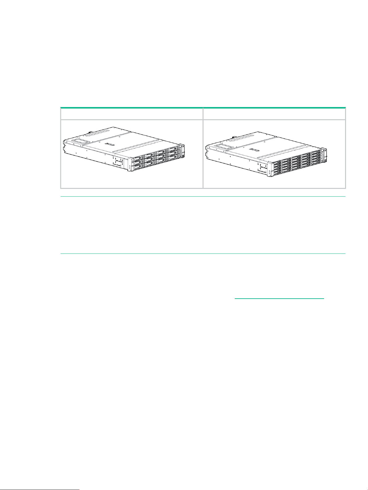
The HPE 12Gb SAS disk enclosures are available in two models:
• D3600: supports up to 12 Large Form Factor (LFF) SAS drives for a maximum capacity of
7.2 TB with 600GB SAS drives or 48 TB with 4 TB SAS MDL or 4TB SATA MDL drives.
• D3700: supports up to 25 Small Form Factor (SFF) SAS drives for a maximum capacity of
30 TB with 1.2 TB SAS drives or 25 TB with 1 TB SAS MDL or 1 TB SATA MDL drives.
NOTE: Each enclosure is shipped with an optional Digital Rain bezel which customers can
install as needed. The graphics in this guide are portrayed without the bezel for clarity.
D3700 SFF EnclosureD3600 LFF Enclosure
NOTE: Depending on your disk enclosure model and controller installation environment, one
or more disk enclosures can be cascaded from the disk enclosure that is connected to the
controller. For more information, see the QuickSpecs for the disk enclosure, available on the
D3000 website.
Hardware components
For a parts diagram, see “Component identification” (page 40)
To order a replacement part, contact an Hewlett Packard Enterprise-authorized service provider
or see the Hewlett Packard Enterprise Parts Store online: http://www.hpe.com/buy/parts
Hardware components 5
Page 6

2 Removal and replacement procedures
Required tools
The following items are required for some procedures:
• T-8 Torx screwdriver
• T-10 Torx screwdriver
• T-15 Torx screwdriver
• Phillips screwdriver
Required items
Items required for installation include the following, some of which ship with the disk enclosure:
• Rack mounting kit
• Disk enclosure
• Disk drives and drive blanks
• SAS controller or controller enclosure
• SAS cables
• MiniSAS HD cables
NOTE: The included MiniSAS HD cables can be used with the 12Gb JBOD. In order to
connect the 12Gb JBOD to either a 6Gb Smart Array or to 6Gb HBAs, customers must
purchase the MiniSAS HD to MiniSAS cable.
• Power cables
• Access to a workstation on the server
• Access to the Internet
Safety precautions
Retain and follow all product safety and operating instructions. Always refer to the documentation
(printed or electronic) supplied with your product. If there is a conflict between this document and
the product documentation, the product documentation takes precedence. Observe all warnings
on the product and in the operating instructions to reduce the risk of bodily injury, electric shock,
fire, and damage to the equipment.
General precautions
CAUTION: The installation and maintenance of products must be carried out by qualified
personnel.
If the product sustains damage requiring service, disconnect the product from the AC electrical
outlet and refer servicing to an Hewlett Packard Enterprise authorized service provider. Examples
of damage requiring service include:
• The power cord, extension cord, or plug has been damaged.
• Liquid has been spilled on the product or an object has fallen into the product.
• The product has been exposed to rain or water.
6 Removal and replacement procedures
Page 7
• The product has been dropped or damaged.
• The product does not operate normally when you follow the operating instructions.
To reduce the risk of personal injury or damage to the product:
• Place the product away from radiators, heat registers, stoves, amplifiers, or other products
that produce heat.
• Never use the product in a wet location.
• Avoid inserting foreign objects through openings in the product.
• Move products with casters carefully. Avoid quick stops and uneven surfaces.
Preventing electrostatic discharge
To prevent damaging the system, be aware of the precautions you need to follow when setting
up the system or handling parts. A discharge of static electricity from a finger or other conductor
may damage system boards or other static-sensitive devices. This type of damage may reduce
the life expectancy of the device.
To prevent electrostatic damage:
• Avoid hand contact by transporting and storing products in static-safe containers.
• Keep electrostatic-sensitive parts in their containers until they arrive at static-free workstations.
• Place parts on a grounded surface before removing them from their containers.
• Avoid touching pins, leads, or circuitry.
• Always be properly grounded when touching a static-sensitive component or assembly.
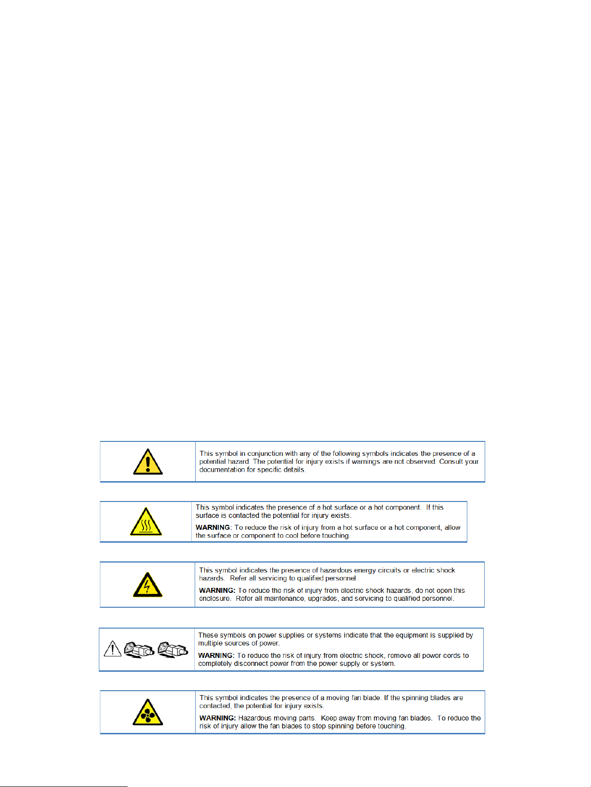
Symbols on equipment
The following symbols may be placed on equipment to indicate the presence of potentially
hazardous conditions:
Safety precautions 7
Page 8

8 Removal and replacement procedures
Page 9
Warning and caution messages
WARNING! To reduce the risk of personal injury or damage to equipment, heed all warnings
and cautions throughout the installation instructions.
WARNING! To reduce the risk of personal injury or damage to the equipment, be sure that:
• The leveling jacks are extended to the floor.
• The full weight of the rack rests on the leveling jacks.
• The racks are coupled together in multiple-rack installations.
• Only one component is extended at a time. A rack may become unstable if more than one
component is extended for any reason.
WARNING! To reduce the risk of personal injury or equipment damage when unloading a rack:
• At least two people are needed to safely unload the rack from the pallet. An empty 42U rack
can weigh as much as 115 kg (253 lb), can stand more than 2.1 m (7 ft) tall, and might
become unstable when being moved on its casters.
• Never stand in front of the rack when it is rolling down the ramp from the pallet. Always
handle the rack from both sides.
WARNING! The enclosure is very heavy. To reduce the risk of personal injury or damage to
the equipment:
• Observe local occupational health and safety requirements and guidelines for manual material
handling.
• Remove all hard drives before installing or moving the enclosures.
• Use caution and get help to lift and stabilize enclosures during installation or removal,
especially when the enclosure is not fastened to the rack.
• Never stack an enclosure on top of another enclosure.
• Never place equipment on top of an enclosure.
• Never place an enclosure on a surface that cannot support up to 163.3 kg (360.0 lb).
WARNING! To reduce the risk of personal injury or damage to the equipment, you must
adequately support enclosures during installation and removal.
WARNING! Always use at least two people to lift an enclosure into the rack. If the enclosure
is being loaded into the rack above chest level, a third person must assist with aligning the
enclosure with the rails while the other two people support the weight of the enclosure.
WARNING! Be sure to install enclosures starting from the bottom of the rack and work your
way up the rack.
WARNING! To reduce the risk of personal injury from hot surfaces, allow the drives and the
internal system components to cool before touching them.
WARNING! To reduce the risk of electric shock or damage to the equipment:
• Never reach inside the chassis while the system is connected to a power source.
• Perform service on system components only as instructed in the user documentation.
WARNING! A risk of electric shock from high leakage current exists. Before connecting the
AC supply to the power enclosures, be sure that the electrical outlets are properly grounded
(earthed).
Safety precautions 9
Page 10

CAUTION: Always be sure that equipment is properly grounded and that you follow proper
grounding procedures before beginning any installation procedure. Improper grounding can result
in ESD damage to electronic components. For more information, see “Preventing electrostatic
discharge” (page 7)
CAUTION: When performing non-hot-plug operations, you must power down the server blade
and/or the system. Use caution when performing other operations, such as hot-plug installations
or troubleshooting.
CAUTION: Protect the equipment from AC power fluctuations and temporary interruptions with
a regulating facility UPS device. This device protects the hardware from damage caused by
power surges and voltage spikes and keeps the system in operation during a power failure.
Precautions for maintaining and servicing products
To reduce the risk of electric shock or damage to the equipment when installing, maintaining, or
servicing products, observe the following precautions:
• Some products contain power supplies that are capable of producing hazardous energy
levels. Refer to the documentation included with your product to determine whether it contains
these power supplies. The installation of internal options and routine maintenance and
service of this product should be performed by individuals who are knowledgeable about
the procedures, precautions, and hazards associated with equipment containing hazardous
energy levels.
• Allow the product to cool before removing covers and touching internal components.
• Do not use conductive tools that could bridge live parts.
• Remove all watches, rings, or loose jewelry when working in hot-plug areas of an energized
server and storage products.
• Do not attempt to defeat safety interlocks (where provided).
• Some products have covers or doors to access hot-plug components and may allow access
to hazardous energy circuits or moving fans.
◦ The doors should remain locked during normal operation.
OR
• The product should be installed in a controlled access location where only qualified personnel
have access to the product.
• Power down the equipment and disconnect all AC power cords before removing any access
covers for non-hot-plug areas.
• Do not replace non-hot-plug components while power is applied to the product. First, shut
down the product and disconnect all AC power cords.
• Do not exceed the level of repair specified in the procedures in the product documentation.
All troubleshooting and repair procedures are detailed to allow only subassembly or
module-level repair. Because of the complexity of the individual boards and subassemblies,
do not attempt to make repairs at the component level or to make modifications to any printed
wiring board. Improper repairs can create a safety hazard.
• Verify that the AC power supply branch circuit that provides power to the rack is not
overloaded. This will reduce the risk of personal injury, fire, or damage to the equipment.
The total rack load should not exceed 80 percent of the branch circuit rating. Consult the
electrical authority having jurisdiction over your facility wiring and installation requirements.
10 Removal and replacement procedures
Page 11

Power cords
To reduce the risk of electric shock or damage to the equipment:
• Use an approved power cord. If you have questions about the type of power cord to use,
contact your Hewlett Packard Enterprise authorized service provider.
• If you have not been provided with a power cord for your product or for any AC-powered
option intended for your product, purchase a power cord that is approved for use in your
country.
• You must use a power cord rated for your product and for the voltage and current marked
on the electrical ratings label of the product. The voltage and current rating of the cord must
be greater than the voltage and current rating marked on the product.
• Do not place objects on AC power cords or cables. Arrange them so that no one may
accidentally step on or trip over them.
• Do not pull on a cord or cable. When unplugging from the electrical outlet, grasp the cord
by the plug.
• Make sure that the total ampere rating of all products plugged into an extension cord or
power strip does not exceed 80 percent of the ampere ratings limit for the extension cord or
power strip.
• Do not disable the power cord grounding plug. The grounding plug is an important safety
feature.
• Plug the power cord into a grounded (earthed) electrical outlet that is easily accessible at
all times.
Power supplies
Hot-plug power supplies are not designed to be removed or installed with AC power connected
to the power supply. To reduce the risk of electric shock or damage to the equipment when
handling hot-plug power supplies:
• Install the power supply before connecting the power cord to the power supply.
• Unplug the power cord before removing the power supply from the product.
• If the system has multiple sources of power, you must unplug all AC power cords from the
power supplies to completely disconnect power from the system.
Verify that the external power source connected to your product matches the type of power source
indicated on the electrical ratings label. If you are not sure of the type of power source required,
consult your authorized service provider or local power company.
Powering off disk enclosures
IMPORTANT: Always power off disk enclosures after controller enclosures and servers.
IMPORTANT: When installing a hot-pluggable component, such as a disk drive, it is not
necessary to power down the enclosure.
To power off a disk enclosure:
1. Power off any attached servers. For more information, see the server documentation.
2. Power off the controller enclosure (if included in the configuration.) For more information,
see the controller enclosure documentation.
3. Disconnect power cords.
The system is now without power.
Powering off disk enclosures 11
Page 12
Powering on
After disk enclosures are physically installed and cabled, power up all devices and verify that
they are operating properly.
Before powering on
Observe the following best practices before powering on the enclosure for the first time:
• Complete the server, controller, or controller enclosure installation. For more information,
see the server, controller, or controller enclosure user documents.
• Install the disk enclosures.
• Install disk drives in the disk enclosures so that the connected host controller can identify
and configure them at power on.
• Connect the SAS cables and power cords to the enclosure.
Power on procedures
1. Connect the enclosure to a live power source.
NOTE: There is no power on/standby button. Power flows to the enclosure immediately
upon connecting to a live power source.
2. Once power is applied to the power supplies, the enclosure starts running.
The power on LED turns solid green.
3. Wait a few minutes for the disk enclosures to complete their startup routines.
CAUTION: If power is applied to the server before the disk enclosures complete their
startup routine, the server might not properly discover the storage.
4. Apply power to the controller enclosure (if included in the configuration).
5. Power on (or restart) the server with access to the disk enclosures, start the operating system,
and log on as administrator.
CAUTION: When you power on the server, the monitor might display a “New Hardware
Found” message. Cancel out of this window to prevent the installation of unsupported
software.
6. Verify that each component is operating properly.
12 Removal and replacement procedures
Page 13
Verifying the operating status of the disk enclosures
To verify that the disk enclosures and disk drives are operating properly, view the enclosure and
disk drive LEDs and compare them with the patterns described in the following table. If LED
patterns are not as expected, check cable connections between the devices, check the availability
of your power source, review the installation procedures, and remove and reinsert the module.
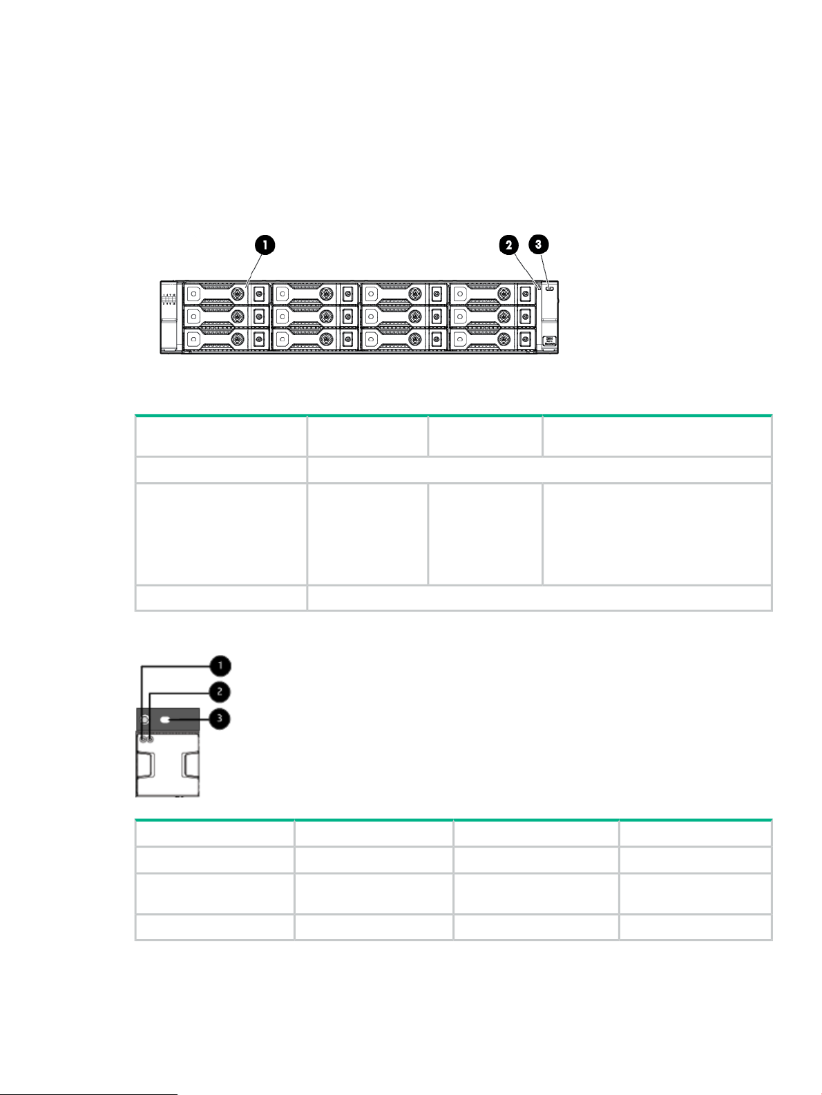
Front panel LEDs
Operating
conditionStartup conditionIndicator
Fault conditions
Fan module
N/A1. HDD
Solid greenSolid green2. Bi-color System Health LED
The UID is a locator LED activated by pressing the rear or the front UID buttons.3. Blue UID LED
• Flashing amber:
non-critical error
• Solid amber:
critical failure
Fault conditionsOperating conditionStartup conditionIndicator
OffOffBlue1. Blue Fan UID LED
LED
Solid amberSolid greenSolid green2. Bi-color Health/Status
OffOffBlue3. Blue System UID
Powering on 13
Page 14
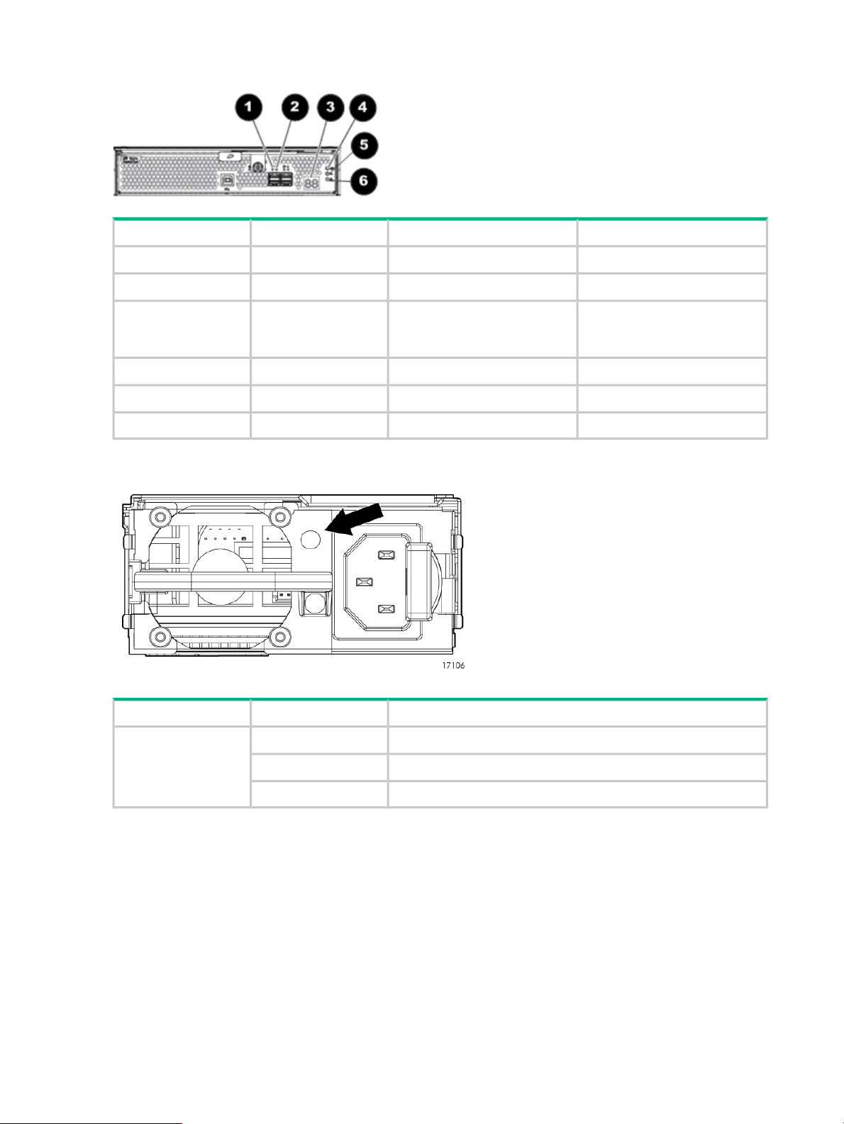
I/O module LEDs
Fault conditionsOperating conditionStartup conditionIndicator
OffBlinking or solid green1. Port Link
Solid amberOff2. Port Error
3. 7–segment display
Power supply module
OffA number, representing the box
number, or an error/warning
code.
OffOffBlue4. UID
OffSolid greenBlinking green5. Health
Blinking or solid amberOff6. Fault
DefinitionStatusIndicator
Verifying the status of the disk drives
Both the HPE G8 LFF and SFF drive carrier system uses I2C communication for drive
authentication, failure and configuration info, activity animation and enhanced LEDs.
14 Removal and replacement procedures
Powering upFlashing greenStatus LED
Normal operationSolid green
No power or faultUnlit
Page 15
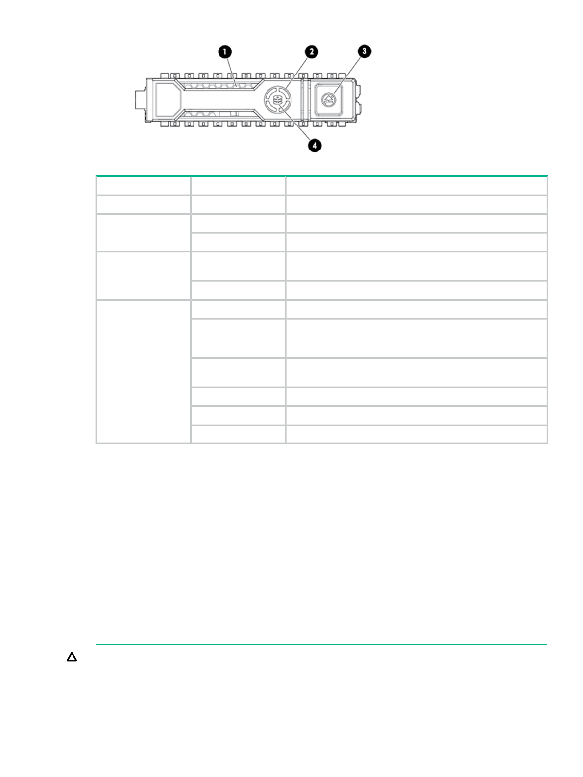
DefinitionStatusIndicator
The drive is being identified by a host application.Solid blue1 Locate
Drive activity.Rotating green2. Activity ring
No drive activity.Off
Hard drive blanks
To maintain the proper enclosure air flow, a disk drive or a disk drive blank must be installed in
each drive bay. The disk drive blank maintains proper airflow within the disk enclosure.
Hard drive
Depending on the types of hard disk drives (HDDs) you are using, the following numbers of drives
can be installed in a single enclosure:
Solid white3. Do not remove
Flashing green
Flashing amber/green
Do not remove the drive. Removing the drive causes one or more
of the logical drives to fail.
Drive is safe to remove. Will not cause a logical drive to fail.Off
The drive is a member of one or more logical drives.Solid green4. Drive status
The drive is rebuilding or performing a RAID migration, stripe size
migration, capacity expansion, or logical drive extension, or is
erasing.
The drive is a member of one or more logical drives and predicts
the drive will fail.
The drive is not configured and predicts the drive will fail.Flashing amber
The drive has failed.Solid amber
The drive is not configured by a RAID controller.Off
• Large form factor (LFF): 12 HDDs
• Small form factor (SFF): 25 HDDs
A variety of disk drive models are supported for use, including dual-ported and single-ported
models. For more information about supported disk drives, see the QuickSpecs for the disk
enclosure, available on the D3000 website.
CAUTION: To prevent improper cooling and thermal damage, operate the enclosure only when
all bays are populated with either a component or a blank.
Hard drive blanks 15
Page 16

Disk drive guidelines
CAUTION:
• Follow industry-standard practices when handling disk drives. Internal storage media can
be damaged when drives are shaken, dropped, or roughly placed on a work surface.
• When installing a disk drive, press firmly to make sure the drive is fully seated in the drive
bay and then close the latch handle.
• When removing a disk drive, press the release button and pull the drive only slightly out of
the enclosure. Then, to allow time for the internal disk to stop rotating, wait approximately
10 seconds before completely removing the drive from the enclosure.
• Always populate hard drive bays starting with the lowest bay number. If only one hard drive
is used, install it in the bay with the lowest device number.
• Disk drives are hot-pluggable.
• SAS and SATA disk drives may be installed in the same enclosure, but cannot be included
in the same RAID logical volume.
Removing a drive
CAUTION: To prevent improper cooling and thermal damage, operate the enclosure only when
all bays are populated with either a component or a blank.
1. Press the release button to open the latch handle.
2. Swing out the latch handle on the drive (1). Then, pull the drive from the bay (2).
Replacing a drive
CAUTION: To prevent improper cooling and thermal damage, operate the enclosure only when
all bays are populated with either a component or a blank.
1. Do one of the following:
• If you are installing the disk drive into an empty bay, remove the drive blank.
16 Removal and replacement procedures
Page 17

• If you are replacing a disk drive, refer to “Removing a drive” (page 16)
2. Unlatch and swing out the latch handle on the drive. Then, slide the drive into the bay (1),
pressing firmly on the drive to seat it. Close the latch handle (2), pressing firmly until it locks
in place.
IMPORTANT: When a drive is inserted in an operational enclosure, the drive LEDs flash
to indicate that the drive is seated properly and receiving power.
3. If you are replacing a drive, confirm that the replacement drive matches the drive that is
being replaced.
4. Determine the status of the hard drive.
IMPORTANT: For proper airflow and cooling, a drive blank must remain installed in all unused
drive bays.
Removing and replacing I/O Cables
NOTE: If the cable is malfunctioning, check the LED displays on the I/O module back panel.
See “I/O module LEDs” (page 14)
1. Confirm the correct port(s) for the cable to be replaced.
2. Disconnect the I/O cable(s) to be replaced.
Removing and replacing I/O Cables 17
Page 18

3. Replace the cable(s).
4. Confirm basic communication using LEDs See “Verifying the operating status of the disk
enclosures” (page 13).
Removing and replacing the I/O module
1. Unplug the two cables from the back panel of the I/O module. See “Removing and replacing
I/O Cables” (page 17)
2. Loosen the captive retaining thumbscrew (1), and swing out the hood latch (2).
3. Slide out the I/O module (3) and set aside.
4. Then, slide the replacement I/O module into the correct bay and swing in the hood latch until
it closes.
5. Re-tighten the captive retainer thumbscrew.
6. Replace the two I/O cables.
7. Read the LEDs to confirm the unit is operating. See “I/O module LEDs” (page 14)
Removing and replacing a power supply
1. Remove the power cable from the power supply to be replaced.
18 Removal and replacement procedures
Page 19

2. Press the latch (1) and slide module out (2).
3. Slide new power supply into the enclosure bay until it clicks into place.
4. Replace the power cable.
5. Confirm that the system is in normal state. See “Verifying the operating status of the disk
enclosures” (page 13).
Removing and replacing the fan module
1. Pinch the release buttons and slide the module out.
2. Slide in new fan module until it clicks into place
Removing and replacing the fan module 19
Page 20

3. Confirm that the system is in normal state. See “Verifying the operating status of the disk
enclosures” (page 13).
20 Removal and replacement procedures
Page 21

Removing and replacing the fan control card
This operation is performed after Hewlett Packard Enterprise Support determines that the
enclosure is the source of the issue and requests the fan control card to be replaced
WARNING! Check to make sure data on the drives is backed up Back up data if required.
1. Unplug the power cables.
2. Remove I/O cables. See “Removing and replacing I/O Cables” (page 17)
3. Remove the fan modules. See “Removing and replacing the fan module” (page 19)
4. Remove the rear CTO hold down bracket.
5. Remove the enclosure from the rack. See “Removing and replacing the enclosure” (page 22)
6. Pull hood latch up and back (1 and 2), and lift enclosure cover up and remove (3).
7. Remove fan control card cable (1).
8. Loosen the T-15 captive thumbscrew (2).
9. Slide the fan control card sideways to free it from the retaining pins and lift out (3).
10. Insert the new fan control card and slide sideways to engage it with the retaining pins.
11. Re-tighten the captive T-15 thumbscrew.
12. Attach the fan control card cable.
13. Replace the enclosure cover and press the hood latch down to latch.
14. Replace the enclosure in rack. See “Removing and replacing the enclosure” (page 22)
15. Tighten the front retaining screws.
CAUTION: The front CTO retaining screws must be attached at all times when the
enclosure is racked.
Removing and replacing the fan module 21
Page 22

16. Replace the fan modules. See “Removing and replacing the fan module” (page 19)
17. Replace the I/O module cables. See “Removing and replacing the I/O module” (page 18)
18. Replace the power cables.
19. Apply power to the enclosure and confirm the system is powered on. See “Verifying the
operating status of the disk enclosures” (page 13)
20. Confirm that the system is operating normally. See “Verifying the operating status of the disk
enclosures” (page 13)
Removing and replacing the enclosure
The operation is performed after Support determines that the enclosure is the source of the issue
and requests the enclosure be replaced
WARNING! Check to make sure data on the drives is backed up. Back up the data if required.
1. Unplug the power cables.
2. Remove I/O cables. See “Removing and replacing I/O Cables” (page 17)
3. Label drives for removal.
4. Remove the drives. See “Removing a drive” (page 16)
5. Remove power supplies See “Removing and replacing a power supply” (page 18)
6. Remove the I/O modules. See “Removing and replacing the I/O module” (page 18)
7. Remove both fan modules. See “Removing and replacing the fan module” (page 19)
8. Loosen the captive CTO screws behind the latch on the front left and right bezel ears of the
chassis (1)
9. Loosen the rear CTO hold-down bracket.
10. Slide the enclosure out of the rails (2) and set it on a secure surface.
WARNING! Always use at least two people to lift an enclosure into the rack. If the enclosure
is being loaded into the rack above chest level, a third person must assist with aligning the
enclosure with the rails while the other two people support the weight of the enclosure.
11. Slide in the new enclosure and tighten the retaining screws.
12. Re-attach the rear CTO hold-down bracket.
13. Replace the I/O modules. See “Removing and replacing the I/O module” (page 18)
14. Replace the power supplies. See “Removing and replacing a power supply” (page 18)
15. Replace the fan modules. See “Removing and replacing the fan module” (page 19)
16. Replace the hard drives and/or SSDs. See “Replacing a drive” (page 16)
17. Replace I/O module cables. See “Removing and replacing the I/O module” (page 18)
22 Removal and replacement procedures
Page 23

18. Replace power cables and connect the cables to a live power source.
19. Confirm system is powered on and that it is operating normally. See “Verifying the operating
status of the disk enclosures” (page 13)
Removing and replacing the Power Distribution Board
This operation is performed after Support determines that the enclosure is the source of the issue
and recommends that the Power Distribution Board be replaced.
WARNING! Check to make sure data on the drives is backed up. Back up data if required.
1. Unplug the power cables.
2. Remove the I/O cables. See “Removing and replacing I/O Cables” (page 17)
3. Remove power supplies See “Removing and replacing a power supply” (page 18)
4. Remove the enclosure. See “Removing and replacing the enclosure” (page 22)
5. Pull up hood latch and remove enclosure cover.
6. Remove the power supply cables.
7. Loosen the captive T-15 thumbscrew (1) on the air guide.
8. Lift up the air guide and then pull toward front of enclosure to remove (2).
9. Loosen the T-15 captive thumbscrew on the Power Distribution Board.
10. Slide the Power Distribution Board toward the front of the enclosure and lift out of the
enclosure.
11. Replace Power Distribution Board in the enclosure and slide toward the back of the enclosure.
12. Tighten the captive T-15 screw to secure the Power Distribution Board.
13. Attach power cables to the backplane.
14. Replace air guide making sure cables are routed through the air guide opening.
15. Tighten the captive T-15 screw to secure the air guide in the enclosure.
16. Replace enclosure cover and press lever down to latch.
17. Replace enclosure in rack. See “Removing and replacing the enclosure” (page 22)
18. Replace the power supplies. See “Removing and replacing a power supply” (page 18).
19. Replace the I/O module cables. See “Removing and replacing the I/O module” (page 18).
20. Replace power cables and connect the cables to a live power source.
21. Confirm system is powered on and that it is operating normally. See “Verifying the operating
status of the disk enclosures” (page 13)
Removing and replacing the Power Distribution Board 23
Page 24

Removing and replacing the UID-health module
This operation is performed after Support determines that the UID-health module is the source
of the issue and requests the module be replaced
WARNING! Check to make sure data on the drives is backed up. Back up data if required
1. Unplug the power cables.
2. Remove the I/O cables. See “Removing and replacing I/O Cables” (page 17)
3. Remove the fan module(s) with the failed control card. See “Removing and replacing the
fan module” (page 19)
4. Remove enclosure from rack. See “Removing and replacing the enclosure” (page 22)
5. Pull up hood latch and remove enclosure cover.
6. Disconnect the rear UID-Health module cable from the backplane.
7. Remove the UID-Health module retaining screw (1).
8. Slide out the UID-Health module (2) while guiding the cable through the enclosure.
WARNING! The UID cable is adhered to the chassis. Care should be taken to remove it.
The cable could become unusable.
9. Replace the UID-Health module by sliding the cable through the slot in the enclosure.
10. Reconnect the UID-Health module cable to the backplane.
11. Fasten the UID-Health module using the retaining screw.
12. Replace enclosure cover and press hood latch down to latch.
13. Replace the enclosure in the rack. See “Removing and replacing the enclosure” (page 22)
24 Removal and replacement procedures
Page 25

14. Tighten the retaining screws. See “Removing and replacing the enclosure” (page 22)
15. Replace the fan modules. See “Removing and replacing the fan module” (page 19).
16. Replace the I/O module cables. See “Removing and replacing the I/O module” (page 18)
17. Replace power cables and connect the cables to a live power source.
18. Confirm system is powered on and that it is operating normally. See “Verifying the operating
status of the disk enclosures” (page 13)
Removing and replacing the enclosure backplane
This operation is performed after Support determines that the backplane is the source of the
issue and requests the backplane be replaced
WARNING! Check to make sure data on the drives is backed up. Back up data if required.
1. Unplug the power cables.
2. Remove I/O cables. See “Removing and replacing I/O Cables” (page 17)
3. Label drives for removal.
4. Remove the drives. See “Removing a drive” (page 16)
5. Remove power supplies See “Removing and replacing a power supply” (page 18)
6. Remove I/O modules. See “Removing and replacing the I/O module” (page 18)
7. Remove fan modules. See “Removing and replacing the fan module” (page 19)
8. Remove enclosure. See “Removing and replacing the enclosure” (page 22)
9. Pull up hood latch and remove enclosure cover.
10. Disconnect the following cables from the backplane:
CableNumber
Front UID health module1
Fan control card2
Fan control card3
Rear UID health module4
Power distribution unit5
Rear UID health module6
Power supply7
Power supply8
11. Remove the eight T-10 drive cage retaining screws. There are four to a side.
Removing and replacing the enclosure backplane 25
Page 26

NOTE: Depending on whether the drive cage is for LFF or SFF drives, the screws are in
slightly different locations.
12. Slide the drive cage toward the front of the enclosure and lift free of the enclosure.
13. Remove the two T-15 screws attaching the back plane to the drive cage.
14. Slide the back plane toward the top of the drive cage and lift the back plane off the drive
cage.
15. Place the new back plane on the drive cage and slide toward the bottom of the drive cage
on to the retaining hooks.
16. Replace the two T-15 back plane screws.
17. Place the drive cage in the enclosure and slide toward the back of the enclosure making
sure the locating pins in the bottom of the enclosure are all correctly located in the drive
cage.
NOTE: Depending on the specific unit, there are 6 or 8 locating pins.
18. Replace the eight T-10 drive cage retaining screws.
19. Connect the two UID/Health module cables.
20. Connect the power cables.
21. Connect the fan control card cables.
22. Replace the cover and press lever down to secure.
23. Replace the enclosure in the rack. See “Removing and replacing the enclosure” (page 22)
24. Replace the I/O modules. See “Removing and replacing the I/O module” (page 18)
25. Replace the power supplies. See “Removing and replacing a power supply” (page 18)
26. Replace the fan modules. See “Removing and replacing the fan module” (page 19)
27. Replace the hard drives and/or SSDs. See “Replacing a drive” (page 16)
28. Replace I/O module cables. See “Removing and replacing the I/O module” (page 18)
29. Replace power cables and connect the cables to a live power source.
30. Confirm system is powered on and that it is operating normally. See “Verifying the operating
status of the disk enclosures” (page 13)
26 Removal and replacement procedures
Page 27

Installing the rail kit
The disk enclosure can be installed into most standard server racks. To verify that your rack is
supported for use with the disk enclosure, see the QuickSpecs for the disk enclosure at the
website: http://www.hpe.com/products/quickspecs.
CAUTION: Install disk drives in the enclosures only after mounting the enclosures in the rack.
• A disk enclosure populated with disk drives is too heavy to lift safely by a single person.
• Movement of a disk enclosure during installation might damage the internal storage media
of installed disk drives.
Rack installation best practices
In addition to industry-standard recommendations, consider the following:
• Locate the heaviest items, such as uninterruptible power supplies (UPS) and additional disk
enclosures near the bottom of the rack.
• To make cabling easy, install the disk enclosures below the server.
• Install similar components next to each other in the rack. Because disk enclosures, switches,
and servers are of differing depths, if you have more than one of a device, mount those
devices adjacent to one another to accommodate working behind the rack.
WARNING! To reduce the risk of personal injury or damage to the equipment, be sure that:
• At least two people lift the storage system during removal or installation if the weight exceeds
22.7 kg (50 lb). If the system is being loaded into the rack above chest level, a third person
MUST assist with aligning the system with the rails while the other two people support the
weight of the system.
• The leveling jacks on the rack are extended to the floor.
• The full weight of the rack rests on the leveling jacks.
• The stabilizing feet are attached to the rack if it is a single-rack installation.
• The racks are coupled together in multiple-rack installations.
• Only one component in a rack is extended at a time. A rack might become unstable if more
than one component is extended.
• To prevent damage and to ease insertion of the device into the rack, support the weight of
the device and keep it level when sliding it into the rack.
Installing the rail kit 27
Page 28

Procedures
1. Position left and right rack rails at the desired 'U' position in the rack, adjusting the rails to
2. Use guide pins to align the shelf mount kit to the RETMA column holes.
3. To engage the rear, push the rail toward the back of the rack until the spring hook (1) snaps
fit the rack, as needed.
Front and Rear bottom edge of rails must align with the bottom of EIA boundary in the
lowermost 'U'
NOTE: Rails are marked L and R with an arrow indicating the direction in which the rail
should be installed.
into place.
4. To engage the front, pull the rail towards the front of the rack to engage the spring hook with
the RETMA column in the same manner as the rear spring hook.
NOTE: Make sure that the respective guide pins for the square or round hole rack align
properly into RETMA column hole spacing.
5. Secure rear of rack rail to the RETMA column with either the round- or square-hole shoulder
screws provided in the package.
6. Secure front of rail to the front RETMA column using the provided flat securing screw/guide
pin in the bottom screw position of the rail.
7. Slide the enclosure into position on the rails (1). Secure the chassis into the rack by tightening
the captive CTO screw behind the latch on the front left and right bezel ears of the chassis
(2).
CAUTION: The front CTO screw must be attached at all times when racked.
28 Removal and replacement procedures
Page 29

8. Attach rear hold down brackets by sliding the tab with the arrow pointed forward (1) into the
corresponding slot on the left and right side of the rear of the chassis. Use the black headed
thumb screw to secure tightly to the rail (2).
Installing the rail kit 29
Page 30

3 Troubleshooting
If the enclosure does not initialize
IMPORTANT: After a power failure, the system automatically returns to the On state when
A/C power is restored, except in the following cases:
• If both power supplies are damaged.
• If there is a single power supply in the system, and it is damaged.
1. Ensure that power has been applied to the enclosure.
2. Verify that the power LED is green.
3. Verify that the power source is working:
a. Verify that the power supplies are working by viewing the power supply LEDs. If
necessary, remove and reinstall the power supplies to verify that they are seated properly.
b. Remove and inspect AC power cords from both power supplies and reconnect them.
Diagnostic steps
Is the enclosure front fault LED amber?
ActionsPossible ReasonsAnswer
Yes
• Front Status and UID module
might not be inserted properly,
might have a damaged connector,
or might have failed.
No action required.System functioning properly.No
• Be sure that the Front Status and
UID module is undamaged and is
fully seated.
• Check rear fault LEDs to isolate
failed component.• Possible error condition exists.
• Contact an authorized service
provider for assistance.
30 Troubleshooting
Page 31

Is the enclosure rear fault LED amber?
ActionsPossible ReasonsAnswers
No action requiredFunctioning properly.No
Yes
Rear power and UID module might
not be inserted properly, might have
a damaged connector, or might have
failed.
Is the System Health LED amber?
Yes
• The system might have
• The system midplane might need
Is the power supply LED green?
No
• Power cords not connected or AC
• Power supply not functioning
• Be sure that the rear power and UID
module is undamaged and is fully
seated.
• Contact an authorized service
provider for assistance.
Possible SolutionsPossible ReasonsAnswer
No action required.System functioning properly.No
• Be sure that all components are
experienced a short. Controller
firmware might be corrupted.
replacement.
power is unavailable.
properly. • Replace with a known-good power
fully seated.
• Update controller firmware.
• Contact an authorized service
provider for assistance.
ActionsPossible ReasonsAnswers
• Remove and inspect the AC power
cords from both power supplies and
reconnect them.
supply.
Yes
normally.
Is the I/O module fault LED amber?
Yes
• The I/O module is locked.
• The I/O module has failed.
• Other fault condition exists.
No action required.The component is functioning
Possible SolutionsPossible ReasonsAnswer
No action required.Functioning properly.No
• Make sure that the I/O module is
seated properly by pressing the I/O
module firmly into its bay after the
handle has clicked in place.
CAUTION: Never remove an I/O
module from the chassis while the
status LED is green. Removing an
active I/O module can result in data
loss.
• Contact an authorized service
provider for assistance.
Diagnostic steps 31
Page 32

Is the fan LED amber?
ActionsPossible ReasonsAnswers
No action requiredFunctioning properly.No
Yes
Fan might not be inserted properly,
might have a damaged connector, or
might have failed.
• Be sure that the fan is undamaged
and is fully seated.
• Contact an authorized service
provider for assistance.
32 Troubleshooting
Page 33

Recognizing disk drive failure
In an Hewlett Packard Enterprise enclosure, a steadily glowing fault LED indicates that a disk
drive has failed. Other indications of failed disk drives are as follows:
• ACU represents failed drives with a distinctive icon.
• HPE SIM can detect failed drives remotely across a network. (For more information about
SIM, see the documentation on the Management CD.)
• ADU lists all failed drives.
• Operating System log files
For additional information about diagnosing disk drive problems, see the HPE ProLiant servers
troubleshooting guide.
Effects of a disk drive failure
When a disk drive fails, all logical drives that are in the same array are affected. Each logical
drive in an array might be using a different fault-tolerance method, so each logical drive can be
affected differently.
• RAID0 configurations cannot tolerate drive failure. If any physical drive in the array fails, all
non-fault-tolerant (RAID0) logical drives in the same array also fail.
• RAID1+0 configurations can tolerate multiple drive failures as long as no failed drives are
mirrored to one another (with no spares assigned).
• RAID5 configurations can tolerate one drive failure (with no spares assigned).
• RAID6 with ADG configurations can tolerate simultaneous failure of two drives (with no
spares assigned).
Compromised fault tolerance
If more disk drives fail than the fault-tolerance method allows, fault tolerance is compromised,
and the logical drive fails.
Factors to consider before replacing disk drives
Before replacing a degraded drive:
• Open SIM and inspect the Error Counter window for each physical drive in the same array
to confirm that no other drives have any errors. For details, see the SIM documentation on
the management cd.
• Be sure that the array has a current, valid backup.
• Use replacement drives that have a capacity at least as great as that of the smallest drive
in the array. The controller immediately fails drives that have insufficient capacity.
Recognizing disk drive failure 33
Page 34

To minimize the likelihood of fatal system errors, take these precautions when removing failed
drives:
• Do not remove a degraded drive if any other drive in the array is offline (the online LED is
off). In this situation, no other drive in the array can be removed without data loss.
• Exceptions:
When RAID1+0 is used, drives are mirrored in pairs. Several drives can be in a failed
◦
condition simultaneously (and they can all be replaced simultaneously) without data
loss, as long as no two failed drives belong to the same mirrored pair.
◦ When RAID6 with ADG is used, two drives can fail simultaneously (and be replaced
simultaneously) without data loss.
◦ If the offline drive is a spare, the degraded drive can be replaced.
• Do not remove a second drive from an array until the first failed or missing drive has been
replaced and the rebuild process is complete. The rebuild is complete when the Online LED
on the front of the drive stops blinking.
Exceptions:
◦ In RAID6 with ADG configurations, any two drives in the array can be replaced
simultaneously.
◦ In RAID1+0 configurations, any drives that are not mirrored to other removed or failed
drives can be simultaneously replaced offline without data loss.
Automatic data recovery (rebuild)
When you replace a disk drive in an array, the controller uses the fault-tolerance information on
the remaining drives in the array to reconstruct the missing data (the data that was originally on
the replaced drive) and write it to the replacement drive. This process is called automatic data
recovery, or rebuild. If fault tolerance is compromised, this data cannot be reconstructed and is
likely to be permanently lost.
Time required for a rebuild
The time required for a rebuild varies considerably, depending on several factors:
• The priority that the rebuild is given over normal I/O operations (you can change the priority
setting by using ACU).
• The amount of I/O activity during the rebuild operation.
• The rotational speed of the disk drives.
• The availability of drive cache.
• The model and age of the drives.
• The amount of unused capacity on the drives.
• The number of drives in the array (for RAID5 and RAID6 with ADG).
Allow approximately five minutes per gigabyte without any I/O activity during the rebuild process.
This figure is conservative, and newer drive models usually require less time to rebuild.
34 Troubleshooting
Page 35

System performance is affected during the rebuild, and the system is unprotected against further
drive failure until the rebuild has finished. Therefore, replace drives during periods of low activity
when possible.
CAUTION: If the Online LED of the replacement drive stops blinking and the amber fault LED
glows, or if other drive LEDs in the array go out, the replacement drive has failed and is producing
unrecoverable disk errors. Remove and replace the failed replacement drive.
When automatic data recovery has finished, the online LED of the replacement drive stops
blinking and begins to glow steadily.
Failure of another drive during rebuild
If a non-correctable read error occurs on another physical drive in the array during the rebuild
process, the Online LED of the replacement drive stops blinking and the rebuild abnormally
terminates. If this situation occurs, restart the server. The system might temporarily become
operational long enough to allow recovery of unsaved data. In any case, locate the faulty drive,
replace it, and restore data from backup.
Handling disk drive failures
If the controller was configured with hardware fault tolerance, complete the following steps after
a disk drive failure:
1. Determine which physical drive failed. On hot-plug drives, an amber drive failure LED
illuminates.
2. If the unit containing the failed drive does not support hot-plug drives, perform a normal
shutdown.
3. Remove the failed drive and replace it with a drive that is of the same capacity. For hot-plug
drives, after you secure the drive in the bay, the LEDs on the drive each flash once in an
alternating pattern to indicate a successful connection. The online LED flashes, indicating
that the controller recognized the drive replacement and began the recovery process.
4. Power on the server, if applicable.
5. The controller reconstructs the information on the new drive, based on information from the
remaining physical drives in the logical drive. While reconstructing the data on hot-plug
drives, the online LED flashes. When the drive rebuild is complete, the online LED is
illuminated.
Recognizing disk drive failure 35
Page 36

I/O module error codes
This table describes the possible error codes appearing in the 7–segment display on the back
panel of the I/O module. For information on the location of the 7–segment display, see “I/O module
LEDs” (page 14)
Recommended ActionError DetailError CodeError Type
Error
A2
A3
A4
A6
A8
A9
AE
ESP generic errorA0I/O Module
ESP watchdog is firedA1
ESP Conflict in SAS
domain (domain A/B)
Error in Expander
communication
Missing information in
IO Module
manufacturing NVRAM
I2C arbitration errorA5
Error in inter ESP
communication
Error in GPIO Expander
I2C bus
Permanent error in ESP
NVRAM I2C bus
Error in ESP event logAD
Permanent error in
Backplane I2C bus
1. Remove the module, wait 10 seconds, reinsert the
module.
2. If the error persists, then check for new firmware
releases and upgrade the enclosure firmware. New
firmware versions, containing new features and
defect fixes, are released periodically.
3. If the error persists, contact an Hewlett Packard
Enterprise representative. An I/O module
replacement may be necessary.
Firmware Error
AF
B1
B2
B3
B5
BD
BF
A7I/O Module
Error in Backplane
NVRAM access
Expander generic errorB0
Expander watchdog is
fired
Expander conflict in
SAS domain (side A/B)
Expander using default
SAS address
I2C arbitration errorB4
Error in inter Expander
communication
System event log errorB7
Error in ESP
communication
System identification
value is not available
ESP firmware version
mismatch with ESP
firmware version in
partner I/O module
1. Update the firmware of the I/O module that displays
the error and wait until it restarts.
2. Then update the firmware of the other I/O module
and wait until it restarts.
36 Troubleshooting
Page 37

Recommended ActionError DetailError CodeError Type
Error
Error
B6
B8
BE
B9SAS Cable
BA
Expander firmware
version mismatch with
Expander firmware
version in partner I/O
module
Expander firmware
image error
Expander firmware
version mismatch with
ESP firmware version in
own I/O module
SAS cable hardware
error
Hewlett Packard
Enterprise unsupported
SAS cable
Error in disk driveBBDisk Drive
1. Verify the SAS cable status indicators. For the cables
with an amber LED (error), check if the cables are
properly connected in both sides.
2. If the cables are properly connected and the error
persists, replace the cables.
3. If replacing the cables does not resolve the issue,
then check for new firmware releases. A firmware
upgrade might fix the issue
4. If there is no new firmware available, or upgrading
the firmware is not possible, contact an Hewlett
Packard Enterprise representative. An I/O module
replacement may be necessary.
Check your storage administration software for more
information about the problem detected and how to
properly fix it.
Control Error
Shutdown
Alarms
BC
C0Thermal
C1
C2
C3Thermal
C4
C5
Not authentic drive in
the enclosure
Generic temperature
error
Permanent error in
temperature sensor I2C
bus
Error reading data from
temperature sensor
Warning temperature
reached in temperature
sensor
Critical temperature
reached in temperature
sensor
Minimum temperature
reached in temperature
sensor
There is at least one non-authentic HPE disk drive on
the system. Non-authentic disks may not work properly
on this system.
Check your storage administration software for more
information about the problem detected and how to
properly fix it.
1. Remove the module, wait 10 seconds, reinsert the
module.
2. If the error persists, then check for new firmware
releases and upgrade the enclosure firmware. New
firmware versions, containing new features and
defect fixes, are released periodically.
3. If the error persists, contact an Hewlett Packard
Enterprise representative. An I/O module
replacement may be necessary.
Check for thermal issues, such as extremely hot drives,
air blockages, missing or failed fans, or high ambient
temperature.
C6
Fans commanded to
maximum speed
I/O module error codes 37
Page 38

Recommended ActionError DetailError CodeError Type
Module Error
C7
D0Power Supply
D1
D2
D3
DA
DB
System shutdown
because of over
temperature
Generic error in Power
Supply module 1
Generic error in Power
Supply module 2
Absence of the Power
Supply module 1
Absence of the Power
Supply module 2
Error in system voltageD9
Input power loss in
Power Supply module 1
Input power loss in
Power Supply module 2
If a power supply module does not have a green LED
illuminated, verify that it is correctly cabled to a power
source.
NOTE: This warning can also be caused by a failed
power supply.
1. If cabling was not the root cause, troubleshoot by
reinserting each power supply in turn.
2. If the error persists, then check for new firmware
releases and upgrade the enclosure firmware. New
firmware versions, containing new features and
defect fixes, are released periodically.
3. If the error persists, contact an Hewlett Packard
Enterprise representative. A power supply
replacement may be necessary.
• Verify that the power supply is tightly inserted in the
slot.
• If a power supply is missing, then insert a module in
the empty slot and connect it to a power source.
If a power supply module does not have a green LED
illuminated, verify that it is correctly cabled to a power
source.
NOTE: This warning can also be caused by a failed
power supply.
1. If cabling was not the root cause, troubleshoot by
reinserting each power supply in turn.
2. If the error persists, then check for new firmware
releases and upgrade the enclosure firmware. New
firmware versions, containing new features and
defect fixes, are released periodically.
3. If the error persists, contact an Hewlett Packard
Enterprise representative. A power supply
replacement may be necessary.
Module
Communication
Error
Error
38 Troubleshooting
D4Power Supply
D5
D6
E0Fan Module
E1
Permanent error in
Power Supply modules
I2C bus
Communication error
with Power Supply
module 1
Communication error
with Power Supply
module 2
Generic error in Fan
module 1
Generic error in Fan
module 2
1. Remove and reinsert each power supply in turn.
2. If the error persists, then check for new firmware
releases and upgrade the enclosure firmware. New
firmware versions, containing new features and
defect fixes, are released periodically.
3. If the error persists, contact an Hewlett Packard
Enterprise representative. A power supply
replacement may be necessary.
1. If a fan module has an amber LED indication, try
removing and reinserting it. If none of the fans have
an amber LED, replace one fan module and wait 30
seconds.
2. If the error persists, then check for new firmware
releases and upgrade the enclosure firmware. New
firmware versions, containing new features and
defect fixes, are released periodically.
3. If the error persists, contact an Hewlett Packard
Enterprise representative, a fan module replacement
may be necessary.
Page 39

Recommended ActionError DetailError CodeError Type
Communication
Error
E2
E3
E9 1. If a fan module has an amber LED indication, try
EA
E4Fan Module
E5
E6
Absence of the Fan
module 1
Absence of the Fan
module 2
Failure in one or more
rotors of Fan module 1
Failure in one or more
rotors of Fan module 2
Permanent error in Fan
modules I2C bus
Communication error
with Fan module 1
Communication error
with Fan module 2
• Verify that the fan module is tightly inserted in the
slot.
• If a fan module is missing, then insert a module in
the empty slot.
reinserting it.
2. If none of the fans have an amber LED, replace one
fan module and wait 30 seconds.
3. If the error persists, then check for new firmware
releases and upgrade the enclosure firmware. New
firmware versions, containing new features and
defect fixes, are released periodically.
4. If the error persists, contact an representative, a fan
module replacement may be necessary.
1. Remove and reinsert each fan module in turn.
2. If this does not resolve the issue, then remove and
reinsert the I/O module that shows the status code.
3. If the error persists, then check for new firmware
releases and upgrade the enclosure firmware. New
firmware versions, containing new features and
defect fixes, are released periodically.
4. If the error persists, contact an representative, a fan
module replacement may be necessary.
I/O module error codes 39
Page 40

4 Component identification
40 Component identification
Page 41

CSR statusDescription
1. Chassis Bezel Ear
2. Chassis Bezel Ear
Not a CSR part (part of
drive cage)
Not a CSR part (part of
drive cage)
Not a CSR part3. Drive Cage
Mandatory4. Backplane
Mandatory5. Fan module interconnect board
Mandatory6. Air guard
Mandatory7. Voltage Regulator Module (VRM) or power module
Mandatory8. Power supply
Not a CSR part9. Enclosure
Mandatory10. I/O module
Mandatory11. Fan module
Mandatory12. Rear Unit ID
Mandatory13. Disk drive
41
Page 42

5 Technical specifications
Physical specifications
HPE D3600 LFF: 3.44 x 17.64 x 23.54 in (8.7 x 44.8 x 59.8 cm)Height/Width/Depth
HPE D3700 SFF: 3.44 x 17.64 x 21.48 in (8.7 x 44.8 x 54.6 cm)
No disk drives: 38 lb (17.2 kg)Weight
D3700 SFF fully populated with SFF disk drives: 54.90 lb (24.9 kg)
D3600 fully populated with LFF disk drives: 60 lb (27.2 kg)
Power and environmental specifications
shown are for sea level. An altitude rating of
1°C per 300 m (1.8°F per 1,000 ft) to 3048 m
(10,000 ft) is applicable. The upper limit might
be limited by the type and number of options
installed.)
humidity of 95% is based on a temperature of
45°C (113°F). Altitude maximum for storage
corresponds to a pressure minimum of 70
KPa.)
Shipping
50° to 104° F (10° to 40° C)OperatingTemperature range (Temperature ratings
-22° to 149° F (-30° to 65° C)
NOTE: Rated 1°C per 1000 feet of elevation
to 10,000 ft.
10% to 90% relative humidity (Rh)OperatingRelative humidity (Non-operating maximum
0% to 95% relative humidity (Rh)Non-operating
Maximum wet bulb temperature
rate is 457 m/min (1500 ft/min))
specifications are maximum values and apply
to worst-case conditions at full rated power
supply load. The power/heat dissipation for
your installation will vary depending on the
equipment configuration.)
Acoustic noise levels
Listed are the declared A-Weighted sound power levels (LWAd) and declared average bystander
position A-Weighted sound pressure levels (LpAm) when the product is operating in a 23°C
ambient environment. Noise emissions were measured in accordance with ISO 7779 (ECMA 74)
and declared in accordance with ISO 9296 (ECMA 109). The listed sound levels apply to standard
shipping configurations. Additional options may result in increased sound levels.
(operating)
storage
(non-operating)
OperatingAltitude (Maximum allowable altitude change
current
82.4° F (28° C)Long-term storage
101.6° F (38.7° C)Short-term
3048 m (10,000 ft) This value might be limited
by the type and number of options installed.
9144 m (30,000 ft)Non-operating
100 to 240 VAC (Common- slot Power Supply)Input voltageInput power (Input Power and Heat Dissipation
50 to 60 Hz (Common-slot Power Supply)Input frequency
120V power source: 6ARated input
240V power source: 3A
526WInput power (max)
42 Technical specifications
LWAd= 7.0 BIdle Acoustic Noise (sound power)
LpAm - 53 dBAIdle Acoustic Noise (sound pressure)
Page 43

LWAd= 7.0 BOperating Acoustic Noise (sound power)
LpAm - 53 dBAOperating Acoustic Noise (sound pressure)
Acoustic noise levels 43
Page 44

6 Support and other resources
Accessing Hewlett Packard Enterprise Support
• For live assistance, go to the Contact Hewlett Packard Enterprise Worldwide website:
www.hpe.com/assistance
• To access documentation and support services, go to the Hewlett Packard Enterprise Support
Center website:
www.hpe.com/support/hpesc
Information to collect
• Technical support registration number (if applicable)
• Product name, model or version, and serial number
• Operating system name and version
• Firmware version
• Error messages
• Product-specific reports and logs
• Add-on products or components
• Third-party products or components
Accessing updates
• Some software products provide a mechanism for accessing software updates through the
product interface. Review your product documentation to identify the recommended software
update method.
• To download product updates, go to either of the following:
Hewlett Packard Enterprise Support Center Get connected with updates page:
◦
www.hpe.com/support/e-updates
◦ Software Depot website:
www.hpe.com/support/softwaredepot
• To view and update your entitlements, and to link your contracts and warranties with your
profile, go to the Hewlett Packard Enterprise Support Center More Information on Access
to Support Materials page:
www.hpe.com/support/AccessToSupportMaterials
IMPORTANT: Access to some updates might require product entitlement when accessed
through the Hewlett Packard Enterprise Support Center. You must have an HP Passport
set up with relevant entitlements.
Websites
44 Support and other resources
LinkWebsite
www.hpe.com/info/enterprise/docsHewlett Packard Enterprise Information Library
www.hpe.com/support/hpescHewlett Packard Enterprise Support Center
Page 45

LinkWebsite
www.hpe.com/assistanceContact Hewlett Packard Enterprise Worldwide
www.hpe.com/support/e-updatesSubscription Service/Support Alerts
www.hpe.com/support/softwaredepotSoftware Depot
www.hpe.com/support/selfrepairCustomer Self Repair
www.hpe.com/info/insightremotesupport/docsInsight Remote Support
www.hpe.com/info/hpux-serviceguard-docsServiceguard Solutions for HP-UX
nl
Storage compatibility matrix
Customer self repair
Hewlett Packard Enterprise customer self repair (CSR) programs allow you to repair your product.
If a CSR part needs to be replaced, it will be shipped directly to you so that you can install it at
your convenience. Some parts do not qualify for CSR. Your Hewlett Packard Enterprise authorized
service provider will determine whether a repair can be accomplished by CSR.
For more information about CSR, contact your local service provider or go to the CSR website:
www.hpe.com/support/selfrepair
Remote support
Remote support is available with supported devices as part of your warranty or contractual support
agreement. It provides intelligent event diagnosis, and automatic, secure submission of hardware
event notifications to Hewlett Packard Enterprise, which will initiate a fast and accurate resolution
based on your product’s service level. Hewlett Packard Enterprise strongly recommends that
you register your device for remote support.
For more information and device support details, go to the following website:
www.hpe.com/info/insightremotesupport/docs
www.hpe.com/storage/spockSingle Point of Connectivity Knowledge (SPOCK)
www.hpe.com/storage/whitepapersStorage white papers and analyst reports
Documentation feedback
Hewlett Packard Enterprise is committed to providing documentation that meets your needs. To
help us improve the documentation, send any errors, suggestions, or comments to Documentation
Feedback (docsfeedback@hpe.com). When submitting your feedback, include the document
title, part number, edition, and publication date located on the front cover of the document. For
online help content, include the product name, product version, help edition, and publication date
located on the legal notices page.
Customer self repair 45
Page 46

A Warranty and regulatory information
For important safety, environmental, and regulatory information, see Safety and Compliance
Information for Server, Storage, Power, Networking, and Rack Products, available at
www.hpe.com/support/Safety-Compliance-EnterpriseProducts.
Warranty information
HPE ProLiant and x86 Servers and Options
www.hpe.com/support/ProLiantServers-Warranties
HPE Enterprise Servers
www.hpe.com/support/EnterpriseServers-Warranties
HPE Storage Products
www.hpe.com/support/Storage-Warranties
HPE Networking Products
www.hpe.com/support/Networking-Warranties
Regulatory information
Belarus Kazakhstan Russia marking
Manufacturer and Local Representative Information
Manufacturer information:
• Hewlett Packard Enterprise Company, 3000 Hanover Street, Palo Alto, CA 94304 U.S.
Local representative information Russian:
• Russia:
• Belarus:
• Kazakhstan:
46 Warranty and regulatory information
Page 47

Local representative information Kazakh:
• Russia:
• Belarus:
• Kazakhstan:
Manufacturing date:
The manufacturing date is defined by the serial number.
CCSYWWZZZZ (serial number format for this product)
Valid date formats include:
• YWW, where Y indicates the year counting from within each new decade, with 2000 as the
starting point; for example, 238: 2 for 2002 and 38 for the week of September 9. In addition,
2010 is indicated by 0, 2011 by 1, 2012 by 2, 2013 by 3, and so forth.
• YYWW, where YY indicates the year, using a base year of 2000; for example, 0238: 02 for
2002 and 38 for the week of September 9.
Turkey RoHS material content declaration
Ukraine RoHS material content declaration
Regulatory information 47
 Loading...