

Page 1

HP D300 Digital Dispenser
Operating Manual
Page 2

HP D300 Digital Dispenser 2
Legal notices
Copyright 2008-2012 Hewlett-Packard Company, L.P.
The HP D300 Digital Dispenser, software and documentation manufactured by the Hewlett-Packard Company, 1000
Circle Boulevard, Corvallis, Oregon 97330. All products made in the U.S.A.
The information contained herein is subject to change without notice.
The only warranties for HP products and services are set forth in the express warranty statements accompanying such
products and services. Nothing herein should be construed as constituting an additional warranty. HP shall not be liable
for technical or editorial errors or omissions contained herein.
Page 3

HP D300 Digital Dispenser
3
Contents
1 Product description
1-1 System requirements ..................................................................................................................................... 6
1-1-1 Hardware ............................................................................................................................................... 6
1-1-2 Software ................................................................................................................................................ 6
1-1-3 Environmental operating conditions ...................................................................................................... 6
1-1-4 Shipping and storage conditions ........................................................................................................... 6
2 Safety
2-1 General safety rules ....................................................................................................................................... 7
2-2 Personal protective equipment ....................................................................................................................... 7
2-3 Possible inhalation hazard ............................................................................................................................. 7
2-4 Pinch hazard .................................................................................................................................................. 7
2-5 Laser safety .................................................................................................................................................... 8
2-6 Electrical safety .............................................................................................................................................. 8
2-7 Electrical emissions safety ................................ ............................................................................................. 8
2-8 Decontamination prior to servicing ................................................................................................................. 9
2-9 Safe disposal of Dispensehead Cassettes and pipette tips ........................................................................... 9
2-10 Ergonomic safety ......................................................................................................................................... 9
2-11 Additional assistance ................................................................................................................................... 9
3 Clean the dispenser
4 Get started
4-1 Start up the dispenser .................................................................................................................................. 11
4-2 Get familiar with the software ....................................................................................................................... 12
4-3 Load an existing plate configuration ............................................................................................................. 14
4-4 Get to know the Options dialog box ............................................................................................................. 16
4-4-1 Options: General ................................................................................................................................. 17
4-4-2 Options: Edit: Units .............................................................................................................................. 17
4-4-3 Options: Edit: Fluid Defaults ................................................................................................................ 18
4-4-4 Options: Edit: Assay Defaults .............................................................................................................. 19
4-4-5 Options: Plate Jitter ............................................................................................................................. 19
4-4-6 Options: Report ................................................................................................................................... 20
4-5 Plate dispense procedure ............................................................................................................................ 21
4-5-1 Initiate plate dispense .......................................................................................................................... 21
4-5-2 Scan and load the well plates .............................................................................................................. 22
4-5-3 Load a Dispensehead Cassette .......................................................................................................... 22
4-5-4 Load fluid into the Dispensehead ........................................................................................................ 23
4-6 View the report ............................................................................................................................................. 27
4-7 Turn off the HP D300 Digital Dispenser ....................................................................................................... 30
5 Create plate configurations
5-1 Create the fluids table .................................................................................................................................. 31
5-2 Edit the Fluids List ........................................................................................................................................ 32
5-3 Edit the well plate ......................................................................................................................................... 33
5-4 Set concentrations or volumes in wells ........................................................................................................ 35
5-5 Use the Paste Special dialog box ................................................................................................................ 38
5-6 Normalize ..................................................................................................................................................... 39
5-7 Randomize ................................................................................................................................................... 41
5-8 Save the plate configuration ......................................................................................................................... 42
5-9 Plate Layout Wizard basics .......................................................................................................................... 43
5-9-1 Create single zone titration1layouts .................................................................................................... 43
5-9-2 Position NoDispense controls .............................................................................................................. 47
5-10 Plate Layout Wizard advanced functions ................................................................................................... 49
Page 4

HP D300 Digital Dispenser
4
5-10-1 Create multizone titration1 layouts .................................................................................................... 49
5-10-2 Create modified range titration1 layouts ............................................................................................ 52
5-10-3 Create titration2 layouts: two fluids per well ...................................................................................... 55
6 Troubleshooting and error messages
6-1 Troubleshooting ........................................................................................................................................... 58
6-1-1 Problems with software ....................................................................................................................... 58
6-1-2 Computer issues .................................................................................................................................. 58
6-1-3 Unable to home stage ......................................................................................................................... 59
6-1-4 Check the A1 location .......................................................................................................................... 59
6-1-5 A1 alignment procedure ...................................................................................................................... 59
6-1-6 Check the fuses and replace if necessary ........................................................................................... 61
6-2 Error messages ............................................................................................................................................ 64
Appendix A
HP D300 Digital Dispenser software basics ....................................................................................................... 70
Appendix B
Glossary ............................................................................................................................................................. 71
Appendix C
Quick Start Guide ............................................................................................................................................... 72
Appendix D
Revision History ................................................................................................................................................. 74
Page 5
HP D300 Digital Dispenser 5
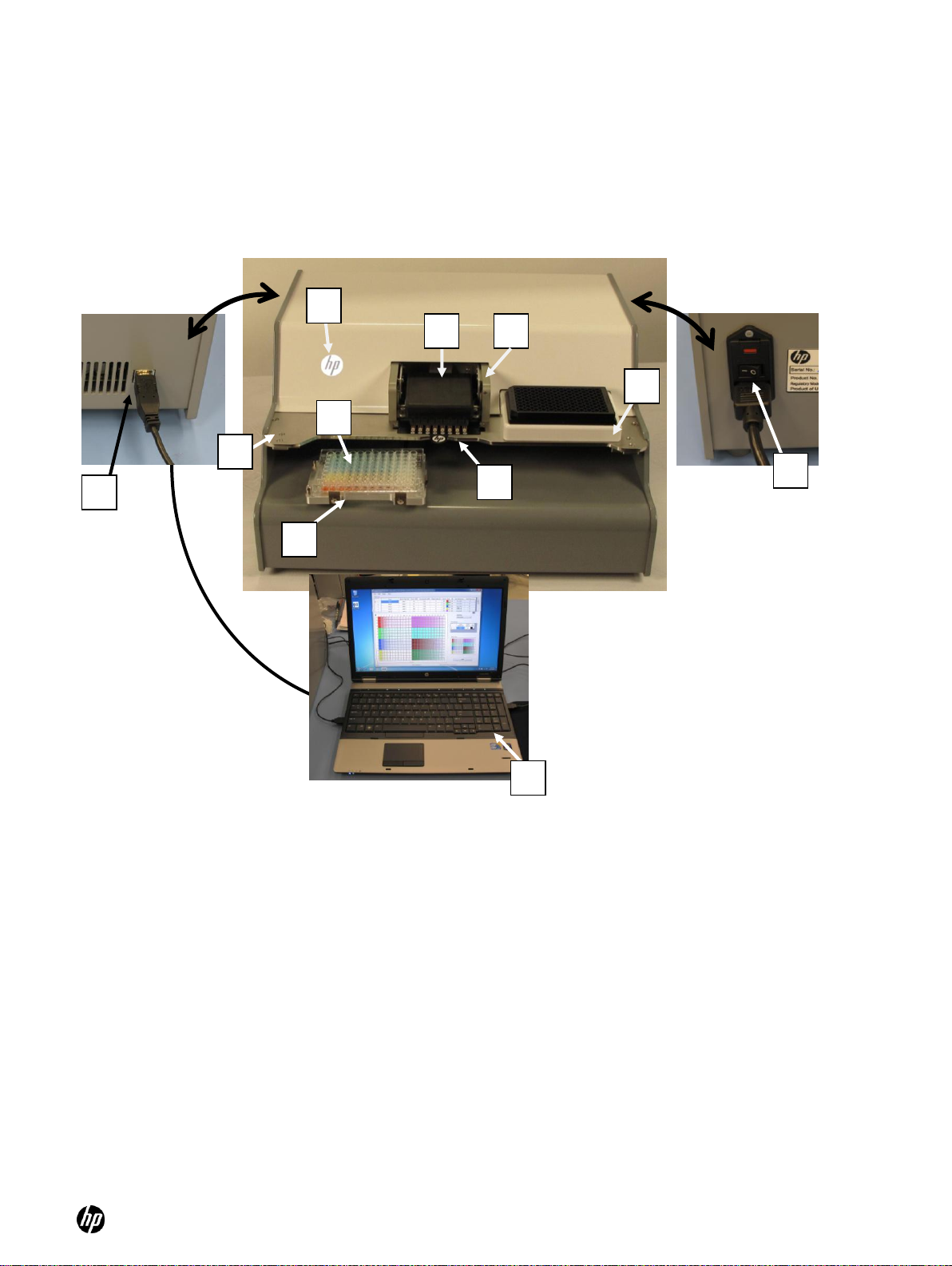
1
Dispensehead Cassette
2
Pogo mechanism
3
Pogo block
4
Source plate holder
5
Motorized stage and destination plate holder
6
Destination plate
7
Deck
8
Power indicator light (HP logo)
9
Dispenser USB connection
10
Power switch
11
PC with D300 software
(Rear view)
(Rear view)
7 9 11
10 4 3
8
1
5
6
2
1 Product description
The HP D300 Digital Dispenser dispenses precise amounts of dilute small molecule compounds in
DMSO into standard 96- and 384-well plates. The dispenser is intended to be used in the lab
environment for drug discovery purposes with small molecules in DMSO.
Page 6

HP D300 Digital Dispenser 6
1-1 System requirements
1-1-1 Hardware
Dimensions of Dispenser (W x D x H): 47cm x 44cm x 24cm
Grounded electrical outlet (2 required, one for dispenser, 1 for PC):
○ 120 V (US) or 230 V (Europe) AC power
1 GHz or faster 32 bit (x86) or 64 bit processor
1 GB (32-bit) or 2 GB (64 bit) RAM
16 GB (32-bit) or 20 GB (64-bit) available disk space
Display: 1024 x 768, 256 colors minimum
USB ports
1-1-2 Software
Microsoft Windows 7, Vista or XP
Microsoft .NET Framework 3.5
○ .NET 3.5 is included with Windows 7
○ .NET 3.5 is available for Windows XP and Vista (www.microsoft.com)
Microsoft Excel 2003 or later
Adobe Acrobat Reader (www.adobe.com/downloads)
Do not adjust text size in Windows – use 100% only
1-1-3 Environmental operating conditions
Temperature: 20C - 30C laboratory conditions (68 - 86F)
Humidity: 30% - 80% RH
1-1-4 Shipping and storage conditions
Temperature: 10C - 32C (50F – 90F)
Humidity: 20% - 80% RH
Page 7

HP D300 Digital Dispenser 7
NOTE: If this unit requires servicing, or you are unsure about any aspect of operation or safety,
contact your Tecan Service Help Desk. The phone number can be found at
http://www.tecan.com/customersupport.
CAUTION: Do not remove any of the dispenser covers. Contact your Tecan Service Help Desk if
the dispenser is not working properly. Do not attempt to repair the dispenser yourself.
CAUTION: Do not place fingers under or on top of the pogo block at any time.
2 Safety
The HP D300 Digital Dispenser is intended to be used in the lab environment for drug discovery
purposes with small molecules in DMSO only. Other uses of the dispenser are not recommended at
this time because they may introduce safety or performance issues.
Under no circumstances should the dispenser be used to dispense bacteria, viruses, cells, biofluids, biologicals, pathogens, contagions, infectious agents, potent toxins, oncogenes, radioactive
materials or other potentially hazardous substances. The dispenser should not be exposed to Bio
Safety Level 3 (BSL3) or greater conditions, contaminants or locations.
The dispenser should be used in accordance with all applicable safety rules that are in effect in the
lab in which it is installed. Usage of the dispenser should also follow common sense safety
guidelines for chemical, mechanical, and electrical safety.
2-1 General safety rules
Place the dispenser on a work surface that supports all four feet securely.
Plug the dispenser into a standard, grounded, electrical outlet. Note the power requirement
(120V in North America or 230V in Europe) listed on the back label of the dispenser.
Avoid the moving parts of the dispenser during operation.
2-2 Personal protective equipment
The HP D300 Digital Dispenser dispenses chemicals normally used by your company. The same
safety precautions and personal protective equipment (PPE) specified by your employer for fluid
transfer operations, such as pipetting into bio-assay well plates, should be used when operating the
dispenser and handling these materials.
2-3 Possible inhalation hazard
The dispenser was designed with chemical safety in mind; however, it does dispense picoliter
droplets of fluid and generates a small amount, less than 1% by volume, of very small aerosol
droplets that might not be trapped within the well plate that you are dispensing into. If the fluids are
known or suspected to be an inhalation hazard or contact hazard, consider using the dispenser in
an exhausted enclosure such as a lab fume hood.
2-4 Pinch hazard
The dispenser was designed with mechanical safety in mind; however, there are potential pinch
points between the pogo block and either the Dispensehead Cassette, the Dispenser deck or the
top cover. This pinch hazard is labeled on the pogo block.
Page 8
HP D300 Digital Dispenser 8
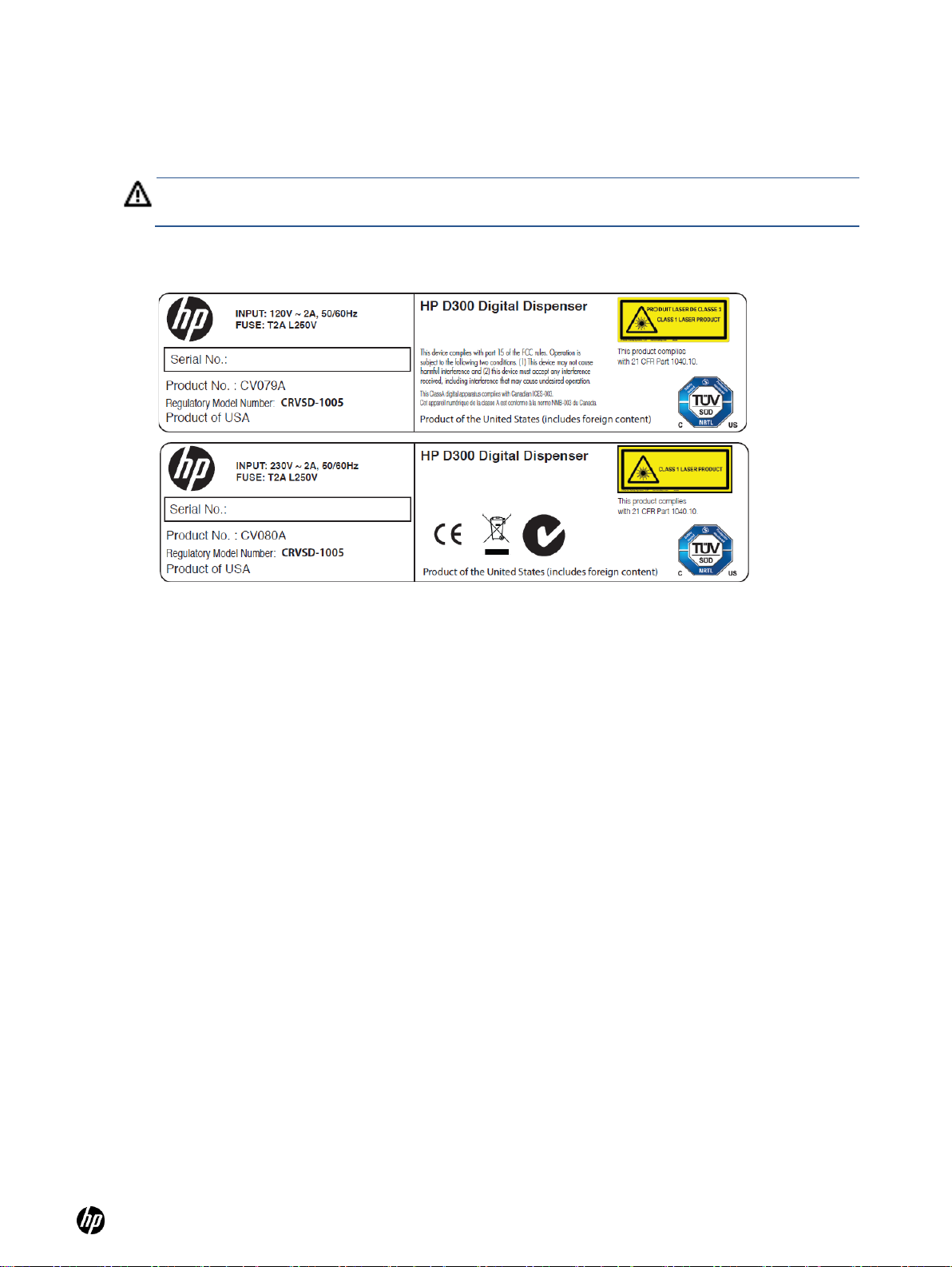
WARNING: Do not look at the laser beam directly. Similarly, do not continue to look at laser light
reflected on a highly reflective substance for a long duration.
2-5 Laser safety
A Class 1 laser is used in the dispenser to determine the height of the destination plate. This Class
1 Laser follows the requirements of Laser Notice No. 50 of the FDA (CDRH), Accession No.
0520365-02. This product complies with 21 CFR Part 1040.10 for laser products. See Figure 2-1.
Figure 2-1 D300 Digital Dispenser rear placards indicating safety certifications for North America
(top) and Europe (bottom)
2-6 Electrical safety
The HP D300 Digital Dispenser has passed a TUV certification for a CUE marking signifying
compliance with applicable electrical regulations in the EU and North America. As shown in Figure
2-1, a placard is attached to the rear of the dispenser, noting this certification and the electrical
specifications of the dispenser: voltage 120V or 230V AC, 1 phase/3 wire, 50/60 Hertz, 2A full load
amperage, and short circuit interrupt rating 5000A. The dispenser includes two user-replaceable
T2A L250V (time lag, low breaking capacity 2A, 250V) fuses contained in the power inlet module at
the rear of the dispenser.
2-7 Electrical emissions safety
The HP D300 Digital Dispenser has passed an FCC/EMC test for electrical emissions safety. This
device complies with part 15 of the FCC Rules. Operation is subject to the following two conditions:
(1) This device may not cause harmful interference, and (2) this device must accept any
interference received, including interference that may cause undesired operation. Any changes or
modifications to this equipment not expressly approved by the Hewlett-Packard Company may
cause harmful interference, and void your warranty.
This equipment has been tested and found to comply with the limits for a Class A digital device,
pursuant to part 15 of the FCC Rules. These limits are designed to provide reasonable protection
against harmful interference when the equipment is operated in a commercial environment. This
equipment generates, uses, and can radiate radio frequency energy and, if not installed and used in
accordance with the instruction manual, may cause harmful interference to radio communications.
Operation of this equipment in a residential area is likely to cause harmful interference in which case
the user will be required to correct the interference at their own expense. Also, this Class A digital
apparatus complies with Canadian ICES -003.
Page 9

HP D300 Digital Dispenser 9
2-8 Decontamination prior to servicing
You may be required by Tecan service personnel to certify that appropriate cleaning,
decontamination, and other abatement of potential threats to Tecan service personnel have been
performed prior to shipping the dispenser for servicing. Recommended cleaning and
decontamination procedures are described in the ―Clean the dispenser‖ section of this manual.
2-9 Safe disposal of Dispensehead Cassettes
and pipette tips
Disposal of used pipette tips and HP Dispensehead Cassettes (DHCs) should be performed in
accordance with your company’s chemical waste procedures. The DHCs do not require any special
disposal procedures except for those required for the chemicals which have been placed in them by
your laboratory.
2-10 Ergonomic safety
The HP D300 Digital Dispenser typically requires a single manual pipetting operation for each
dispensed compound. In most situations, using the HP dispenser in the intended manner decreases
the frequency of shoulder, arm, and wrist motions and so decreases the stress on these joints.
As with any work task, ergonomics are heavily influenced by workstation setup. To minimize
ergonomic risks associated with the use of the dispenser, consider the following work area design
ideas:
Place the dispenser on a work bench at a height that allows for proper visual and physical
access for operators. Having the dispenser too high can lead to greater shoulder elevation
when pipetting into the Dispensehead and having the dispenser too low can lead to increased
neck and back flexion.
If an operator is too short to comfortably access the dispenser, consider moving the dispenser
to a lower bench height. Alternatively, use a footstool or high lab stool that adjusts to the proper
work height.
Place the dispenser close to the front of the work surface to minimize the distance the operator
must reach to pipette into the Dispensehead.
Place the pipette tip disposal receptacle close to the dispenser.
Place the computer keyboard close to the dispenser to minimize reach distance.
Adjust the computer monitor height and screen angle for good physical and visual access
during dispenser operation.
Use a separate mouse rather than the laptop’s touchpad whenever possible.
Perform data analysis at a separate ergonomically designed workstation whenever possible
rather than at the dispenser computer.
2-11 Additional assistance
Contact your local Tecan Service Help Desk for additional assistance. The phone number can be
found at http://www.tecan.com/customersupport.
Page 10
/Clean the dispenser
HP D300 Digital Dispenser
10
WARNING: Observe the following cautions when cleaning the dispenser:
Do not spray cleaning fluid directly onto the Dispenser when a Dispensehead
Cassette is installed. Always avoid exposing unused Dispenseheads to cleaning
fluids.
Do not spray or wipe the ionizer bar that is mounted under the deck between the
plate opening and the Dispenseheads.
Do not spray or wipe the sensors under the Dispenser deck. Doing so could cause
the sensors to become misaligned.
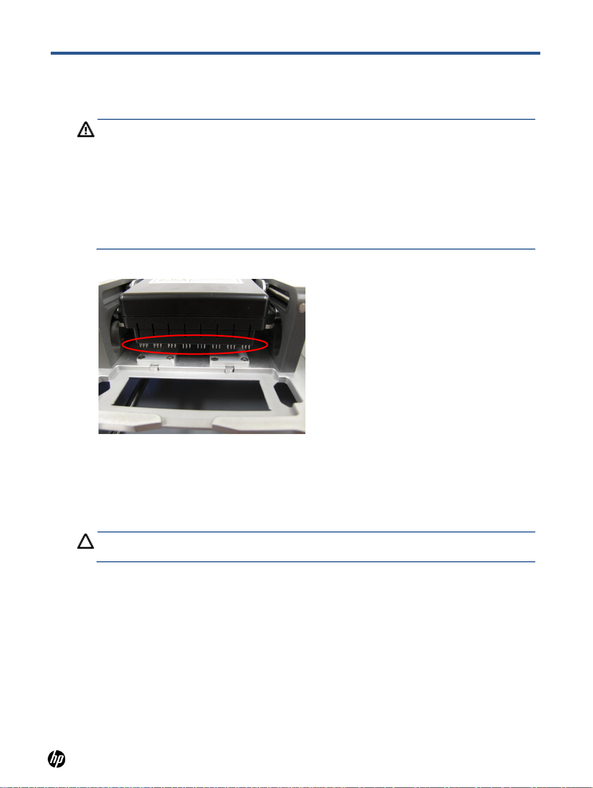
Do not wipe the pogo pins. See Figure 3-2.
CAUTION: Exposing unused Dispensehead Cassettes to cleaning fluids may compromise their
performance.
3 Clean the dispenser
Figure 3-2 Pogo pin region of pogo block which should not be sprayed or wiped with cleaning fluid
As with any lab instrument, it is a best practice to routinely clean areas of the Dispenser that come
into contact with chemicals.
1. Turn off the dispenser as instructed in the ―Turn off the HP D300 Digital Dispenser‖ section
of this document.
2. Remove any unused Dispensehead Cassettes from the Dispenser.
3. Spray a cleaning solution, such as a bleach or a 70% ethanol solution, onto a fabric Texwipe or
other cloth that does not generate particles.
4. Wipe down all accessible Dispenser surfaces, including the following (See the ―Product
description― section for the location of described areas):
○ The top and bottom surfaces of the dispenser deck, avoiding the ionizer bar in the cutout
on the right side of the bottom of the deck and the sensors at the front corners of the deck
○ The pogo mechanism housing, excluding the pogo pin area as described above
○ The destination plate holder
○ The source plate holder
○ All of the outside surfaces of the dispenser
Page 11
HP D300 Digital Dispenser
11
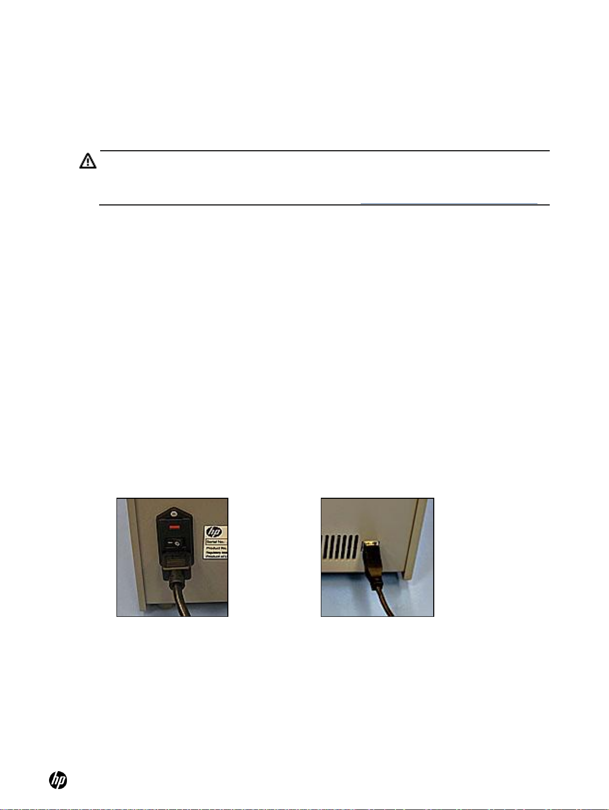
WARNING: Be sure the dispenser matches your outlet voltage. The voltage requirement is shown
on the label on the rear of the dispenser. Do NOT plug the dispenser in to the incorrect voltage.
If the labeled voltage on your dispenser does not match your standard outlet, contact your Tecan
Service Help Desk. The phone number can be found at http://www.tecan.com/customersupport.
Figure 4-3 On/off switch on rear of
dispenser. Depress ―1‖ to turn on.
Figure 4-4 USB port on rear of
dispenser
4 Get started
The HP D300 Digital Dispenser runs on standard AC power, either 120V or 230V, depending on the
Dispenser version. HP Product Number CV079A runs on 120V and CV080A runs on 230V. The
Product Number and the voltage requirement is shown on the label on the rear of the Dispenser.
Two electrical outlets are required, one for the dispenser and another for the computer. A dedicated
circuit is not required as the dispenser draws less than two amps.
The dispenser requires a level bench space which is 50 cm (19 inches) wide, 46 cm (18 inches)
deep, and 26 cm (10 inches) high. This does not include space for the required computer.
4-1 Start up the dispenser
1. Unpackage the dispenser and remove the four pieces of the shipping bracket.
2. Connect the separately packaged power cord to the rear of the dispenser. See Figure 4-3.
3. Plug the other end of the power cord into the appropriate power outlet. See ―Get started.‖
4. Turn the dispenser on using the main power switch adjacent to the power cord connection on
the rear of the Dispenser. Press the ―l‖ on the switch to turn the dispenser on. See Figure 4-3.
5. The HP logo on the front of the dispenser will illuminate and the pogo block LEDs will flash,
indicating the beginning of the Dispenser initialization routine.
6. Use the USB cable that came with the dispenser to connect the computer to the dispenser.
The USB port is on the rear of the dispenser. See Figure 4-4.
7. The first time the Dispenser is connected to the computer, Device Manager will ask you for a
device driver.
8. Insert the CD that was enclosed with the Dispenser into your computer’s disk drive.
9. If your computer does not autorun the installer, use Windows Explorer to locate the setup.exe
file on the CD disk drive.
10. Run setup.exe and follow the on-screen instructions to install both the device driver and the
HP D300 Digital Dispenser software.
Page 12
HP D300 Digital Dispenser
12
11. Check to see if an update is available for your software. Look for the latest version available
and run the *.exe file for it on the Tecan FTP site: ftp.tecan.com
Username: HP-D300
Password: HP+Tecan
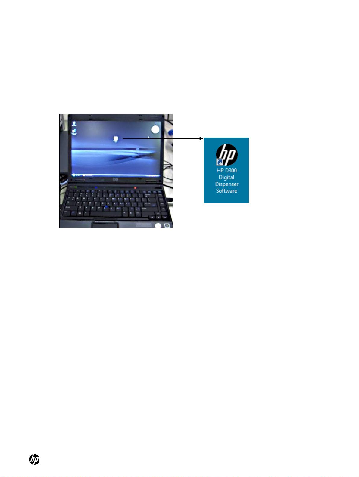
12. Click on the HP D300 Digital Dispenser Software program icon on the computer desktop to
start up the HP D300 Digital Dispenser software. See Figure 4-5.
13. Wait for the Dispenser to go through the software startup routine. The stage will move to the
home position every time the HP D300 Digital Dispenser software is started.
Figure 4-5 Laptop computer showing the HP D300 Digital Dispenser software logo
4-2 Get familiar with the software
Every time the software starts, if the computer is connected to a Dispenser, the computer checks
the Dispenser USB communication, verifies that the dispenser components are operational, and
moves the stage and the pogo mechanism to their home positions. If the computer is not connected
to the Dispenser, the software is fully functional but the GO operation works in a demonstration
mode.
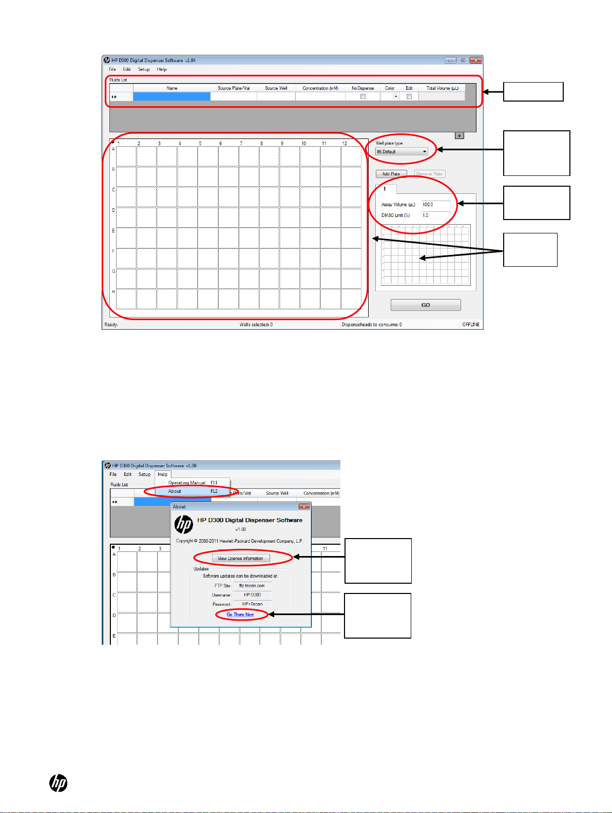
Once the startup routine is complete, the HP D300 Digital Dispenser main operating window
appears, showing an empty Fluids List and an image of an empty well plate. See Figure 4-6.
Page 13
HP D300 Digital Dispenser
13
Software
license
information
Look for
software
updates
Fluids List
Well plate
drop-down
list box
Well plate
images
Plate 1
information
Figure 4-6 HP D300 Digital Dispenser main operating window
The application has a standard MS Windows® look and feel. Once you get started, you can work in
different areas of the main operating window by clicking in them, you can select cells by left-clicking,
control-clicking or shift-click combined with dragging, you can right-click to perform context sensitive
operations, or see information about wells that contain fluids by hovering over them in the well plate.
1. Note that this Operating Manual is accessible two different ways, either by opening the pdf file
in the C:\Program Files\HP-D300 directory, or by clicking on Help/Operating Manual from the
main operating window as shown in Figure 4-7.
Figure 4-7 Help menu and Help/About Window
2. Note that the About window also provides access to the License information and to the Tecan
FTP site that always contains the latest version of the software. Click on Go There Now to
directly access the FTP site from the D300 Digital Dispenser software.
3. Select either 96 or 384 from the Well Plate drop-down list box.
Page 14

HP D300 Digital Dispenser
14
NOTE: Either Set Volume or Set Concentration is available on the well plate options list
depending on whether Volume or Concentration mode was selected in the Options: Edit:
Units. See ―Options: Edit: Units‖ for how to set Volume or Concentration mode.
TIP: If the Set Volume or Set Concentration option is grayed out, the fluids table is empty, so
follow step 4 above to add a fluid to the fluid table.
NOTE: Two different drop volumes are used in the dispenser. For dispense volumes less than
3.5nL, the dispenser uses the closest number of either 13pL or 20pL drops to dispense as close
as possible to the requested volume. For volumes greater than 3.5nL, the dispenser uses the
closest number of 400pL bursts (20 drops simultaneously dispensed from 20 nozzles which are
each 20pL) in order to dispense very close to the requested volume very rapidly.
NOTE: To build a new plate configuration, see ―Create plate configurations‖.
4. Put at least one fluid in the Fluids List, by entering any characters in the Name cell, or by
copying and pasting a list of compounds from an Excel file. The order of the fluids in the Fluids
List is the order in which the fluids will be dispensed.
5. Learn how to select and deselect wells in the plate design:
○ Select any number of wells by clicking and dragging in the well plate image. Any well
which is partially selected becomes one of the selected wells. Give it a try!
○ Select nonadjacent wells by holding down the CTRL key while selecting wells.
○ Deselect wells by clicking on them again while holding down the CTRL key.
○ Deselect all selected wells by clicking on other wells or clicking on the edge of the well
plate (outside the wells) while not holding down the CTRL key.
6. Just for fun, select some wells, then right-click on them to open the Edit Well Plate menu. Click
on Set Volume or Set Concentration, enter the number 1 in the volume or concentration box
and click OK. The wells you selected will turn red because they now contain fluid 1 in your
plate design.
In general, this is a great way to learn to use the software—try things out, right- or left-click
when you are unsure, and move the mouse over areas to check them out.
Don’t worry, you won’t break anything!
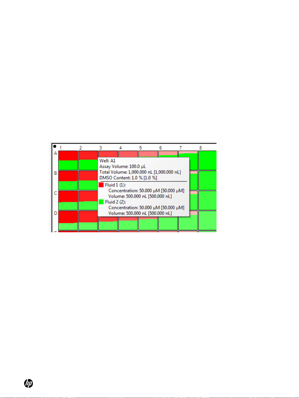
7. Now that you have set up some wells, place the cursor over a colored well and observe the
information that appears in the well pop-ups.
Note that the first three values (assay volume, total volume, and DMSO content) regard the
entire contents of the well. Below these values, information is given separately for each fluid in
that well. With the exception of assay volume, there are two values for each well pop-up entry:
the first value and then a second value enclosed by square brackets, for example [0.960 nl].
The first value is the volume or concentration that was requested, and the second bracketed
value is what will actually be dispensed since only an integer number of drops can be
dispensed. This is where the name Digital Dispenser comes from, an integer number of
ultrasmall droplets.
4-3 Load an existing plate configuration
Page 15
HP D300 Digital Dispenser
15
NOTE: These identifiers may be typed into the Fluids List individually, or they may be entered by
scanning a barcode, or pasted in from an Excel or other tab-separated file that has a compatible
layout. To copy and paste information from another file, the information must be arranged in
columns as the Fluids List is, but it is not necessary that the originating table contain all of the
columns that the Fluids List contains. Once you have pasted information into the Fluids List, if
certain cells (such as those in the Concentration column) do not contain the proper numerical
data, then default values will be used for those cells.
TIP: Paste information from another file into the Fluids List just as you would in any other
Windows program: click in the upper left-most cell that you want to paste into, then right-click and
select Paste.
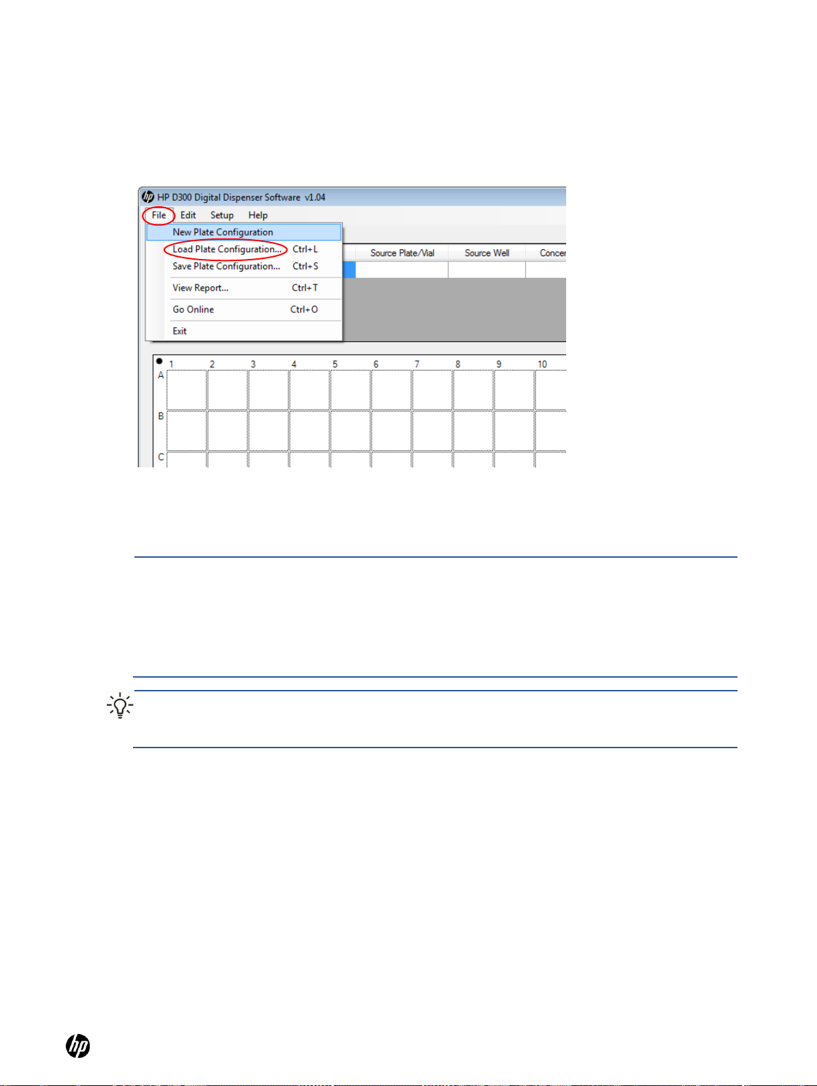
8. On the HP D300 Digital Dispenser main operating window, click File and then Load Plate
Configuration, then locate and select a plate configuration (.xls) that has been previously
saved on your computer. Example configurations are in C:\Program Files\HP-D300\Configs.
Many of the settings, including the Fluids List, assay volume, DMSO limit, plate layout and the
plate jitter option, will change to reflect the configuration you select. See Figure 4-8. Up to
five plates can be included in a Plate Configuration for multiplate configurations.
Figure 4-8 Click File and then Load Plate Configuration
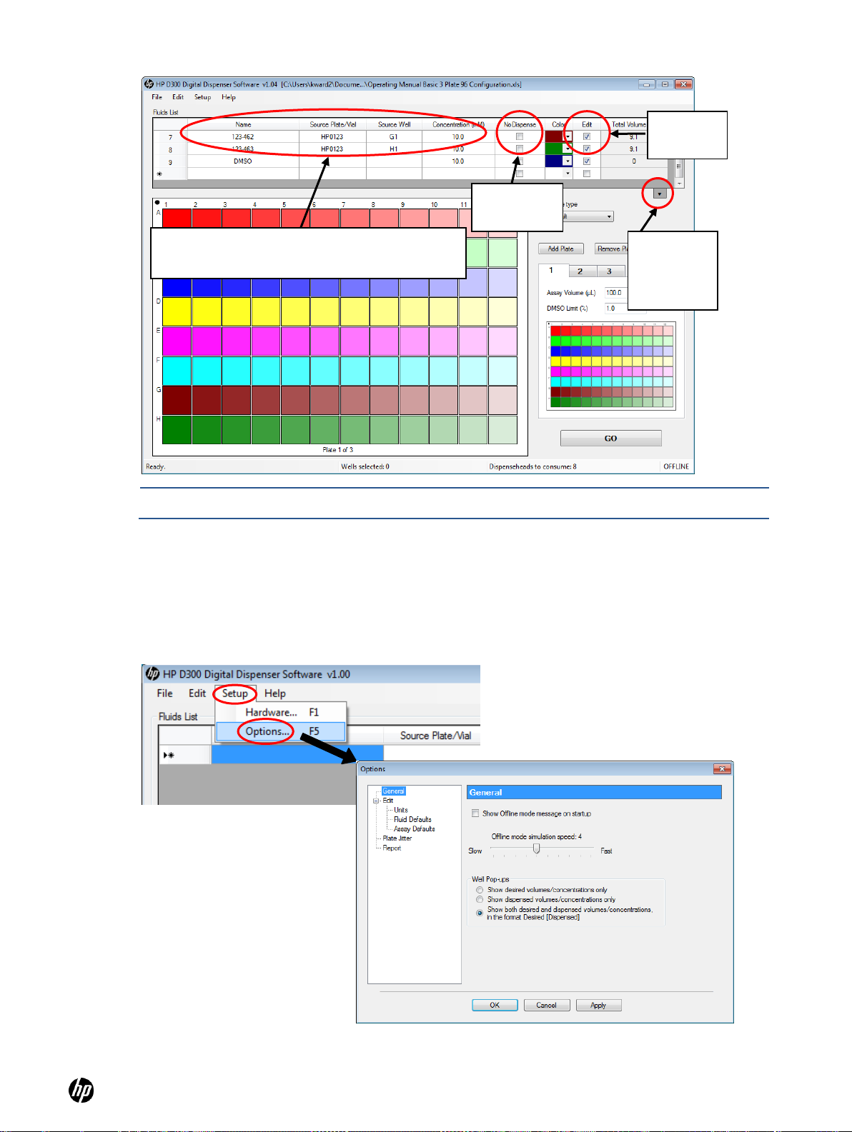
9. If the Fluids List needs to be modified, enter the new fluid name, source plate, source well and
concentration in the Source Plate/Vial, Source Well and Concentration columns in the Fluids
List. Only the fluid name and concentration are required. See Figure 4-9.
○ If the NoDispense check box is selected, you can program that fluid just like the other
fluids, but it will not be dispensed. This may be useful when you want to maintain
information in the output report file about wells that have not been dispensed into. See
Figure 4-9.
○ If the Edit check box is deselected, that fluid cannot be added to the configuration and will
not be displayed in the plate layout. This fluid will still be displayed in the Global View
layout if it was added to any wells prior to deselecting the Edit check box, and it will still be
dispensed. Deselecting the Edit check box may be useful when you have added multiple
fluids to individual wells and want to view or manipulate one or more fluids in the well, but
not all the fluids in the well.
10. Click on the arrow at the lower-right corner of the Fluids List to display the entire Fluids List.
See Figure 4-9.
Page 16
HP D300 Digital Dispenser
16
NOTE: The Fluids List can also be managed by clicking Edit and then Fluids List.
Click here
to view the
entire fluids
list
If necessary, enter the new fluid name, source
plate, source well and concentration here
NoDispense
check-box
Edit
check-box
Figure 4-9 Main operating window showing Fluid Table options.
4-4 Get to know the Options dialog box
At the HP D300 Digital Dispenser main operating window, click Setup and then Options to open
the Options dialog box.
Figure 4-10 Click Setup and then Options to open the Options dialog box
Page 17
HP D300 Digital Dispenser
17
4-4-1 Options: General
From the main operating window, click Setup, then Options , then General to open the General
pane of the Options dialog box. See Figure 4-10. In the General pane, you can choose whether to
show the Offline mode message when you use the software when not connected to an HP D300
Digital Dispenser. When in Offline mode, you can choose how rapidly to ―pseudo-dispense‖ upon
using the Go button using the Offline mode simulation speed. You can also choose whether to
show the requested volume or the dispensed volume, or both, in the Well Pop-ups, as described
below. For small volumes, the dispensed volume may be slightly different than the requested
volume due to the integer number of drops resolution of the Digital Dispenser.
Well pop-ups are the information about the contents of a well that is displayed when you move the
mouse over the well plate image on the main operating window. Note that when ―Show both
requested volume and dispensed volumes/concentrations‖ is selected, the format of the pop-up is
Requested [Dispensed], , as shown in Figure 4-11, such that the requested volumes and
concentrations are shown first and the dispensed volumes and concentrations are shown next,
enclosed in brackets.
Figure 4-11 Example of a well pop-up that displays both requested and [dispensed] volumes and
concentrations
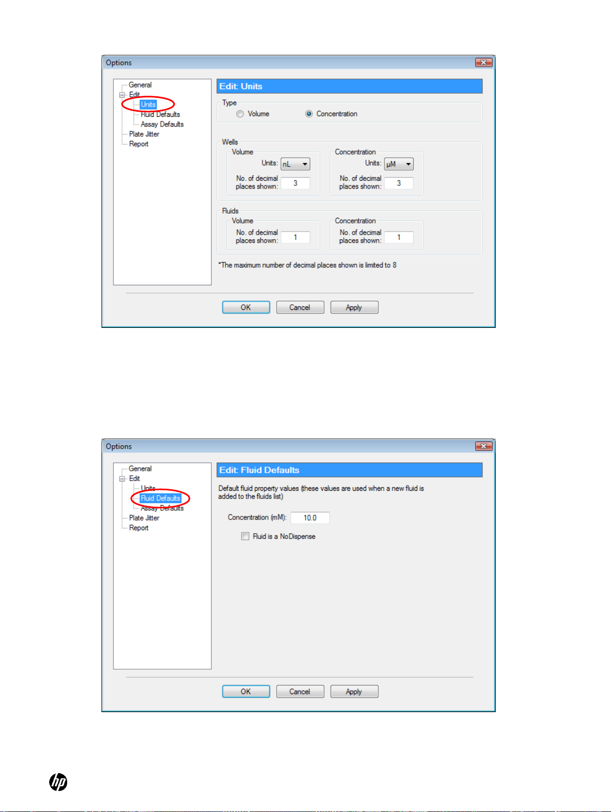
4-4-2 Options: Edit: Units
In the Options dialog box, click Edit and then Units to open the Edit: Units pane of the Options
dialog box. See Figure 4-12.
The Type area of the dialog box allows you to determine whether the setup mode for titrations
is specified using concentration or volume.
The Wells area allows you to specify the unit type for volume and concentration and to specify
the number of decimal places used in plate setup.
The Fluids area allows you to specify the number of decimal places used in the Fluids List.
Page 18
HP D300 Digital Dispenser
18
Figure 4-12 Edit: Units pane of the Options dialog box
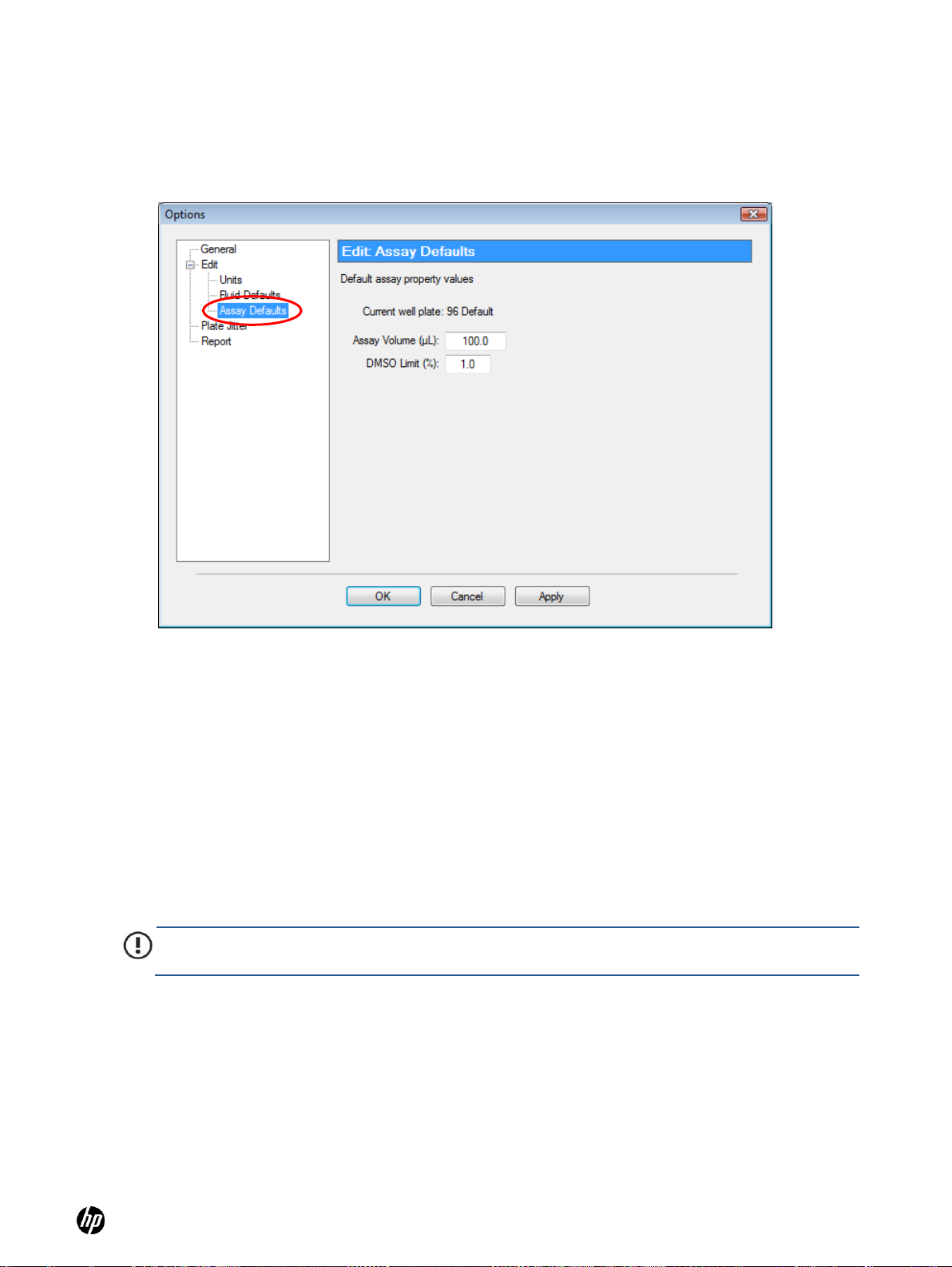
4-4-3 Options: Edit: Fluid Defaults
In the Options dialog box, click Edit and then Fluid Defaults to open the Edit: Fluid Defaults pane
of the Options dialog box. Set the default concentration for new fluids and specify whether default
fluids will be dispensed. See Figure 4-13.
Figure 4-13 Edit: Fluid Defaults pane of the Options dialog box
Page 19
HP D300 Digital Dispenser
19
IMPORTANT: Plate Jitter while dispensing is highly recommended when dispensing directly into
plates containing live cells to reduce the deleterious effect of a DMSO bolus on the cells.
4-4-4 Options: Edit: Assay Defaults
In the Options dialog box, click Edit and then Assay Defaults to open the Edit: Assay Defaults
pane of the Options dialog box. Set the default assay volume and the default DMSO limit here.
See Figure 4-14.
Figure 4-14 Edit: Assay Defaults pane of the Options dialog box
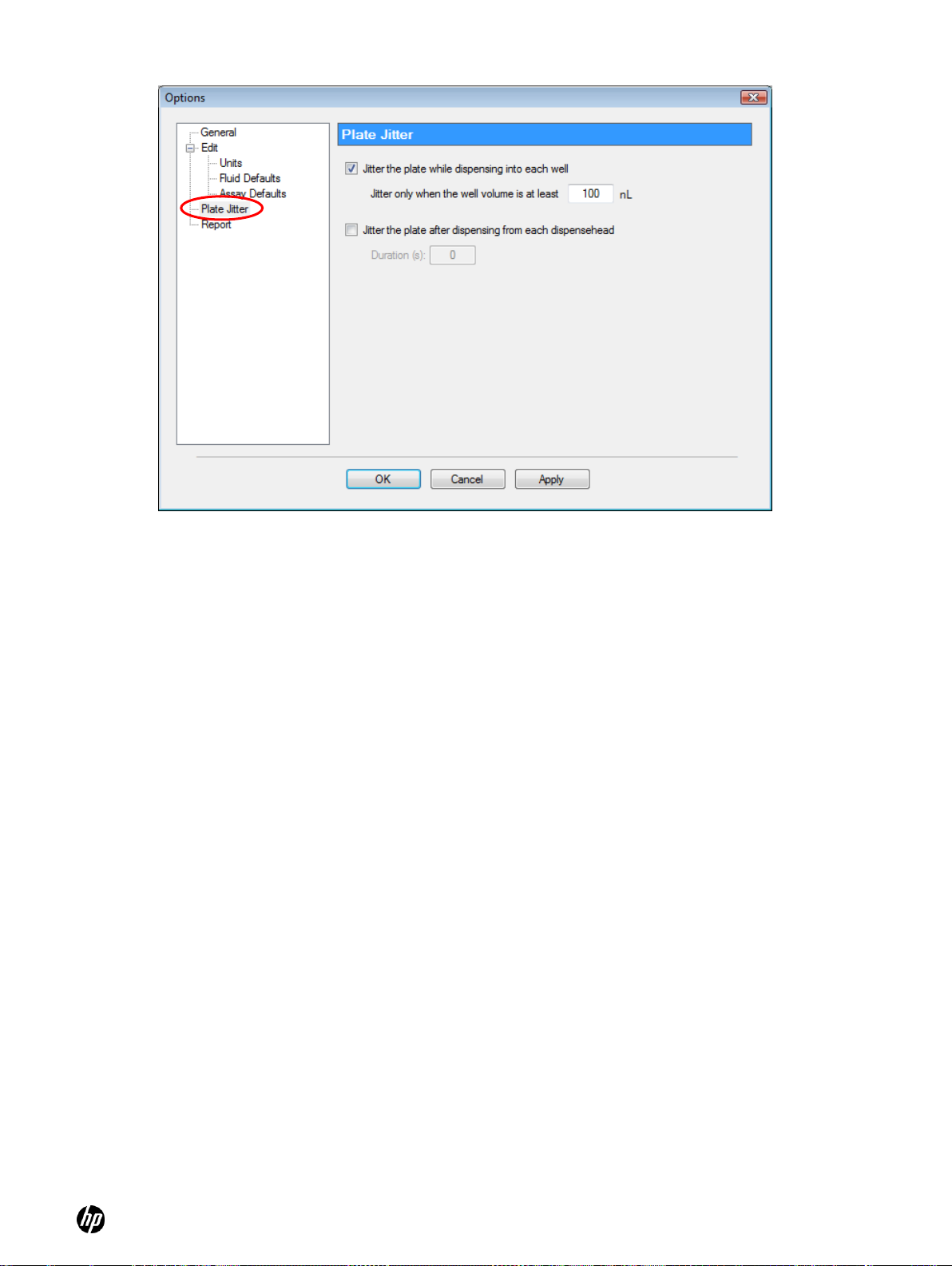
4-4-5 Options: Plate Jitter
In the Options dialog box, click Plate Jitter to open the Plate Jitter pane of the Options dialog box.
See Figure 4-15. Use plate jitter if shaking the destination plate is desired either during and/or after
dispense, for example if you are dispensing into wells containing cells.
Select Jitter the plate while dispensing into each well to shake the destination plate during the
dispense. When this option is chosen, shaking only above a specified volume may be entered.
Typically, only dispense volumes greater than 100nL have a deleterious effect on plated cells.
Additionally, Jitter the plate after dispensing from each Dispensehead may be selected to shake
the destination plate post-dispense. If this option is utilized, enter the number of seconds to shake
after each Dispensehead has completed dispensing.
Page 20
HP D300 Digital Dispenser
20
Figure 4-15 Plate Jitter pane of the Options dialog box
4-4-6 Options: Report
In the Options dialog box, click Report to open the Report pane of the Options dialog box as shown
in Figure 4-16. Use the Report pane to alter options related to the output report that the HP D300
Digital Dispenser software automatically generates after every dispense run (plate). In the Report
pane, you can choose to Display the report after every run, alternatively you would choose
File/View Report or use Excel to view the report after the run. Select Automatically save the
report after every run to save Report files, and Only save if the run was successful to omit
reports for aborted runs. You may also choose to use the default report naming convention by
selecting Use “HP-D300_configurationame_date_time” as the file name and enter the Report
File Path where these reports should be saved, or if this option is not selected, Report File Path will
change to Report File Name where you enter your own report file location and naming convention.
When this option selected, you can choose to rename each new report with automatic incrementing,
overwrite existing reports or to prompt you for a new file name at the completion of each run.
Page 21

HP D300 Digital Dispenser
21
Figure 4-16 Report pane of the Options dialog box
4-5 Plate dispense procedure
4-5-1 Initiate plate dispense
After selecting the desired plate configuration and verifying the options, click the GO button in the
lower-right corner of the main operating window. See Figure 4-17.
Figure 4-17 Main operating window
Page 22
HP D300 Digital Dispenser
22
4-5-2 Scan and load the well plates
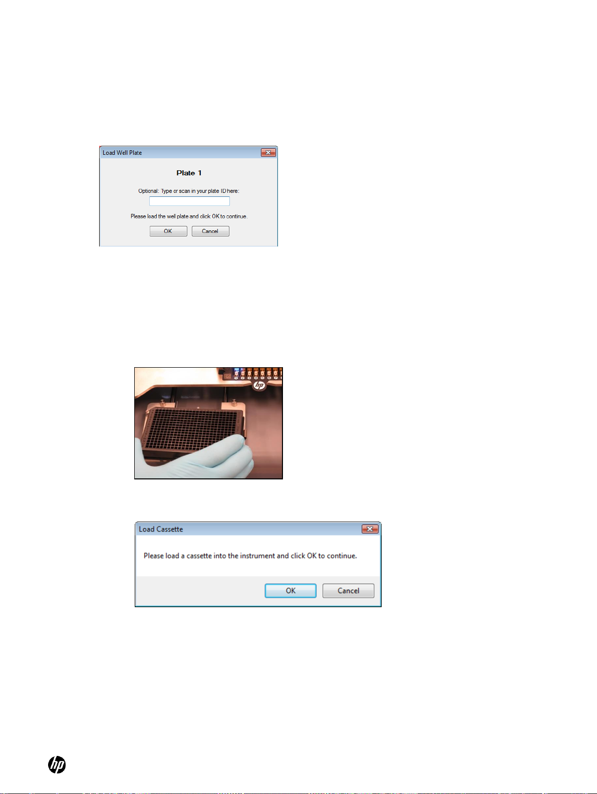
1. Optional. If the destination well plate has an identification code you would like to track, scan
the bar code on the well plate using a USB bar code reader attached to your computer, or
enter its identification number manually into the box on the Load Well Plate dialog box. See
Figure 4-18.
Figure 4-18 Load Well Plate dialog box. Be very careful to load the plate that is requested.
2. Place the well plate on the destination plate holder. See Figure 4-19. Engage the top left
corner of the well plate on the pillars first, then snap the well plate fully into the spring clips.
○ Make sure the plate is completely level and down on the destination plate holder.
○ Ensure that the A1 well position is at the top-left corner of the destination plate holder.
3. Click OK. The Load Cassette dialog box appears. See Figure 4-20.
Figure 4-19 Destination plate holder on the dispenser
Figure 4-20 Load Cassette dialog box
4-5-3 Load a Dispensehead Cassette
1. If a Dispensehead Cassette is already in place with unused Dispenseheads, click OK in the
Load Cassette dialog box to continue (see Figure 4-20). If you are unsure whether there are
any unused Dispenseheads on the Cassette, click OK and the dispenser will test the
Dispenseheads to find which ones are unused.
2. Load a new Dispensehead Cassette if necessary as shown in Figure 4-21:
a. If a Cassette is already loaded in the dispenser, lift the tab with the HP logo and pull the
Cassette out of the deck.
Page 23
HP D300 Digital Dispenser
23
CAUTION: Using a multichannel pipette enables the loading of multiple Dispenseheads
simultaneously. Make sure that you fill the Dispenseheads with the LARGEST load volume of the
set of Dispenseheads you are loading. It is indicated in the upper right of the dialog box (―Max.
Load Volume‖) as shown in Figure 4-22.
b. Lift a new Cassette out of the clamshell container and place it white logo side up into the
cutout on the Dispenser deck.
c. Make sure it is fully inserted so the top surface of the Cassette is the same height as the
top of the deck all the way around the cassette.
Figure 4-21 Loading a new Dispensehead Cassette
3. Once the Cassette is fully inserted, click OK in the Load Cassette dialog box (see Figure 4-
20). The pogo mechanism will engage and the Dispenseheads will be electrically tested to
ensure quality. Then the Load Fluid dialog box appears. See Figure 4-22.
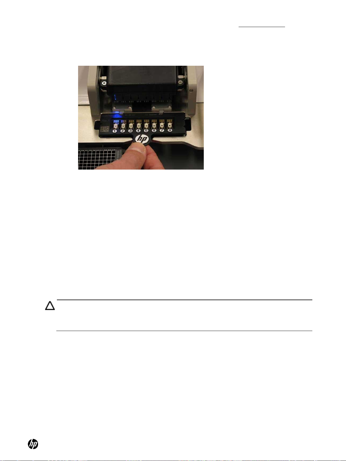
4-5-4 Load fluid into the Dispensehead
When the Load Fluid dialog box opens, the OK and Skip buttons flash above the first Dispensehead
that will be loaded (see Figure 4-22), and a blue LED illuminates the first Dispensehead on the front
of the pogo mechanism.
1. Fill a low volume pipette with at least the amount of fluid that is indicated in the Load Fluid
dialog box, or fill a multipipetter with the appropriate number of fluids in the proper order as
shown in the Load Fluids dialog box. If a multipipetter is used, use the Max. Load Volume for
all Dispenseheads as shown on the right side of the dialog, as circled in Figure 4-22. The
source plate and source well location of the fluid to load will also be identified in the Load Fluid
dialog box if that information was entered in the Fluids List. Be sure to load the proper
compound into the proper Dispensehead.
Page 24

HP D300 Digital Dispenser
24
NOTE: The amount displayed in the Load Volume column in the Load Fluid dialog box
(Figure 4-22) will always be greater than the amount of fluid that was requested to be
dispensed. The volume to be dispensed for each fluid is labelled as the ―Total Volume‖ in
the right hand column of Fluids Table on the main operating window. The difference
between the dispense volume and the load volume is to account for fluid which is retained
in the Dispensehead after dispense, also known as the dead volume. The dead volume is
dependent upon the amount of fluid loaded into the Dispensehead, with greater dispense
volumes leading to greater dead volumes.
NOTE: The maximum amount of fluid that can be dispensed from a Dispensehead is 10μL.
If the total dispense volume of a fluid exceeds 10μL, the volume will be split between two or
more Dispenseheads. The split will be identified in the Load Fluid dialog box and in the
report file (as ―1 of 1‖ or ―1 of 2,‖ for instance). See Figure 4-23 for an example of using two
Dispenseheads per fluid.
Maximum
volume of the
fluids to load on
this cassette
Figure 4-22 Load Fluid dialog box
Page 25

HP D300 Digital Dispenser
25
WARNING: Make sure to load the fluid into the opening on top of the Dispensehead.
Do NOT depress the pipette plunger to the second ―blow out‖ stop as this could introduce
air into the Dispensehead.
Figure 4-24 A blue LED illuminates the
Dispensehead on the Dispensehead Cassette
Figure 4-25 Examples of a good load and a bad load
Good load
Bad load
Figure 4-23 Load fluids dialog box with two Dispenseheads per fluid
2. If you determine that the Dispensehead in the load position is not good, or if you mistakenly
load the Dispensehead incorrectly or with the wrong fluid, press Skip instead of OK. This will
cause the blue LED indicator to move to the next good position, and you will be prompted to
load the fluid that was skipped into that next Dispensehead.
3. Load fluid into the Dispensehead position indicated in the Load Fluid dialog box when
prompted. This Dispensehead will be indicated on the dispenser by an illuminated blue LED.
See Figure 4-24.
Page 26

HP D300 Digital Dispenser
26
WARNING: For multiplate configurations, the D300 software first minimizes the use of
dispenseheads, so that fluids which are used on multiple plates are dispensed into all of
those plates as long as the total dispense volume for that fluid does not exceed 10uL. This
dispensehead conservation can result in a non-intuitive plate loading order. Be careful to
load the correct well plate as prompted by the software! Minimizing the number of
dispenseheads used may sometimes result in more plate swaps than expected.
4. Click OK. All dispensing for the current fluid will occur. In the main operating window, only the
wells for the current fluid are shown, and each well is covered with an X while it is being
dispensed and then turns black when the dispensing for that well is complete.
5. Repeat steps 1 through 4 to load and dispense each fluid in the plate configuration. Fluid
loading can occur during the dispense operation; you do not have to wait until the current
Dispensehead has finished. Just remember to click on OK as each fluid is loaded in its
Dispensehead, or to click on OK All when all Dispenseheads of the current Cassette are
loaded, as shown in Figure 4-26.
6. If loading all Dispenseheads simultaneously with a multichannel pipette or individually prior to
starting the dispense, then after all Dispenseheads of the current Cassette are loaded, click on
OK All as shown in Figure 4-26.
Figure 4-26 Load fluid dialog box showing OK All button
7. After the fluids in the currently loaded cassette are dispensed into plate 1, then depending
upon the configuration, you will be asked to either load a new cassette or a new plate. Read
the prompt dialog box carefully to determine the next step.
8. If you are prompted to load the next plate in the configuration, you will see a prompt similar to
Figure 4-18, where you can enter or scan a name for the plate. If the plate has been loaded
previously, you will be prompted with the plate name you previously entered or scanned in for
the plate, along with the plate number.
Page 27

HP D300 Digital Dispenser
27
9. After the current set of fluids is dispensed into all appropriate plates, if needed the software will
prompt you to load a new cassette using the message shown in Figure 4-20. After a fully used
T8 cassette is removed from the D300 dispenser it may be disposed, as it will not be reused.
10. You will then be shown which fluids to place in each dispensehead of the new cassette as
shown in Figure 4-22, and steps 7 - 9 above will continue until the configuration is complete.
4-6 View the report
Depending on the options selected in the Report pane, a report may be automatically generated and
saved on your computer after the plate dispense operation is completed. To change these report
settings, click Setup, then Options, and then Report (see ―Options: Report‖).
If you have chosen not to display the report after each run, you can still view data from the most
recently completed run by clicking File and then View Report. See Figure 4-27.
Figure 4-27 Open the Report dialog box by clicking File and then View Report
If you are not sure if a report was automatically saved, look at the title bar of the Report dialog box
(see Figure 4-28). If a file name is displayed in the title bar, then the report was automatically
saved. Even if you did not choose to automatically save the report, you can still save the current
report by clicking the Save button in the lower-right corner of the Report dialog box.
Page 28

HP D300 Digital Dispenser
28
Figure 4-28 Report dialog box
When the Report dialog box opens, the Event Log pane is initially displayed, but information about
the fluids and assay volumes can be examined by clicking Fluids or Options in the menu on the left
pane. To view more information about the dispense operation, click the menu options to section of
the report you want to view as shown in Figure 4-29 and Figure 4-30.
Figure 4-29 Report Fluids sheet
Page 29

HP D300 Digital Dispenser
29
Figure 4-30 Report Options sheet
While most data is displayed in rectangular plate format, the Tabulated Results pane displays
concentration data in long skinny columns in order to sort randomized plates. See Figure 4-31.
To derandomize your data in order to create IC50 or EC50 plots, use this report file saved in Excel
format, and add a column of your plate reader data also in this long skinny format. Next, sort the
data by fluid name and concentration in order to process or plot the data by compound and
concentration.
Figure 4-31 Tabulated Results pane
Any previously saved report must be viewed in Excel. If you have trouble finding the reports, the
folder that the last report was saved in is listed in the Report pane of the Options dialog box (click
Setup, then Options…, and then Report).
Page 30

HP D300 Digital Dispenser
30
4-7 Turn off the HP D300 Digital Dispenser
If you are finished using the dispenser and will not use it again for an extended period of time, turn it
off as follows:
1. Close the HP D300 Digital Dispenser software, either by clicking the red X in the upper right
corner of the main operating window, or by clicking on File/Exit.
2. Turn the Dispenser off using the main power switch on the rear of the dispenser. (Press down
the ―O‖ of the rocker switch to turn the dispenser off.)
Figure 4-32 On/off switch in the ON position
3. Remove any unused Dispensehead Cassettes from the dispenser to avoid contamination from
cleaning solutions or the laboratory environment and place them back in the Cassette tray.
4. Clean the dispenser according to the cleaning procedures described in the ―Clean the
dispenser‖ section of this document.
Page 31

HP D300 Digital Dispenser
31
TIP: If desired, information can be entered into the Name, Source Plate/Vial columns by
scanning a bar code, using a USB bar code reader attached to your computer.
TIP: The Fluids List can also be created by copying and pasting information from an Excel
spreadsheet that contains some or all of the fluid data (see ―Get familiar with the
software‖). Fluid information in the Excel file must have columns in the same order as the
Fluids Table.
Plate selection
tabs
Name, Source
Plate/Vial &
Source Well
columns
NoDispense
check box
Concentration
column
Edit check
box
Assay Properties
for current plate
Well Plate dropdown list box
Total Volume
column
5 Create plate configurations
5-1 Create the fluids table
1. On the right side of the main operating window, select the type of well plate you will use from
the Well Plate drop-down list box, either 96 or 384. Up to five plates can be part of a single
configuration, but all of them must be of the same type, 96 or 384. The same fluids, or different
fluids, can used in all the plates in a configuration.
Figure 5-1 The HP D300 Digital Dispenser main operating window
2. Enter one or more fluids (compounds to dispense in this set of plates):
a. Click in a cell in the Name column of the Fluids List and type the name.
b. Optional: click in a cell in the Source Plate/Vial column and type the source plate name.
c. Optional: click in a cell in the Source Well column and type the source well location.
d. Enter the source fluid concentration in the Concentration column.
e. Select a color for each of the fluids in the Color column if you do not want to use the default
colors.
f. Repeat steps a through e for all of the fluids that will be dispensed into this set of well
plates. Up to five plates to be run together can be saved in a single configuration file.
Page 32

HP D300 Digital Dispenser
32
NOTE: If no value is entered into the Concentration column, the default values set in the
Edit: Fluid Defaults pane of the Options dialog box will be used for those cells.
NOTE: If the fluids to be dispensed into a well exceed the DMSO limit, a warning will be
generated and the well pop-up data displayed for that well will appear in red; however, the
Dispenser will dispense whatever concentration/volume you have specified after you have
been warned.
NOTE: These options are also available by right-clicking on selected fluids in the Fluids List.
3. Type the plate assay volume and the DMSO limit for the first plate into the Assay Properties
box. If more than one plate is in a configuration, they may each have different assay volumes
and DMSO limits.
4. In order to program a fluid into wells, the Edit check box in the Fluids List for that fluid must be
selected. When the Edit check box is selected, that fluid can be added or removed from wells,
and is visible in the well plate image. Fluids with the Edit box not checked cannot be added or
removed from wells, and if that fluid was previously programmed into wells, it will remain in the
well plate layout and will be dispensed during the Go process, but will not be shown in the well
plate image. Clear the Edit check box if you want to simplify the view or copy and paste only
some fluids in wells where multiple fluids are being dispensed. The effect of unchecking an
Edit check box is shown in Figure 5-4.
5. To set a fluid or fluids to be non-dispensed, select the NoDispense check box in the Fluids
List. This may be useful when you want to maintain information about nondispensed fluids in
the output report such as for manually or robotically pipetted controls, or for blanks.
6. To program more than one well plate to be run with the same fluids list, select Add Plate. To
remove the current plate from the current configuration, select Remove Plate.
The Total Volume column values cannot be changed. The total volume is the sum of the volume of
a fluid in all of the wells of the plate, also known as the dispense volume of the fluid. This total
volume is less than the volume you will be asked to load in the DispenseHead Cassette due to the
amount of fluid retained in the DispenseHead after dispense, also known as the dead volume.
5-2 Edit the Fluids List
In addition to typing directly into the Fluids List table as described in ―Create the fluids table‖, the
Fluids List can also be edited by clicking Edit and then Fluids List.
1. Select one or more fluids you would like to edit by clicking on the row number (in the left-most
column in the Fluids List). To select multiple fluids, hold down the CTRL key while clicking on
the row number.
2. Click Edit and then Fluids List.
○ Select Enable All for Editing or Disable All for Editing to change all fluids to be shown or
not shown in the well plate image, and able to be added or not to the plate layout.
○ Select Move to Top, Move Up, Move Down, or Move to Bottom to change the order in
which fluids are dispensed into the well plate.
○ Select Delete Fluid to remove the selected fluid from the table.
○ Select Copy, Paste, or Insert Fluid to copy, paste, or insert a fluid into the table.
○ Select Clear Fluids List to remove all fluids from the Fluids List.
Page 33

HP D300 Digital Dispenser
33
TIP: This menu can also be accessed by clicking Edit and then Well Plate after selecting a
well or wells in the well plate image.
Figure 5-2 Edit the Fluids List (or right click within the Fluids Table)
5-3 Edit the well plate
Once the fluid table is set up with at least one compound, Edit Well Plate operations such as adding
fluids to the wells may begin. To see the Edit Well Plate menu options, click on Edit/Well Plate or
select some wells in the well plate image and right-click. As shown in Figure 5-3, the following
options are available:
○ Select or Deselect All Wells
○ Set Titration (see ―Set concentrations or volumes in wells‖, step 3 )
○ Set Concentration or Set Volume (see ―Set concentrations or volumes in wells‖, Step 1)
○ Normalize (see ―Normalize‖)
○ Randomize (see ―Randomize‖)
○ Remove a single fluid and remove all fluids
○ Cut, Copy, Paste, and Paste Special (see ―Use the Paste Special dialog box‖)
○ Clear Well Plate
○ Plate Layout Wizard (see ―Plate Layout Wizard basics‖)
Page 34

HP D300 Digital Dispenser
34
TIP: All of the fluids are shown in the Global View, whereas only the fluids marked for
editing (by selecting the Edit check box in the Fluids List) are shown in the well plate
image. See Figure 5-4.
TIP: If a well does not contain any fluid, it has a dotted outline. The dotted outline is also
used to denote a well that exceeds a dispense condition, such as containing more fluids
than the DMSO limit, or having a requested volume of less than one 13pL drop.
Figure 5-3 Edit Well Plate menu
Each well in the well plate can contain multiple fluids. For example, two fluids of interest in a drugdrug interaction experiment can each be added to the desired wells in the desired sequence of
concentrations or volumes, then a third fluid can be added to the same wells to normalize the wells
to a constant DMSO level. Each fluid is added to the selected wells in a separate programmatic
step.
Page 35

HP D300 Digital Dispenser
35
NOTE: The lowest possible concentration or volume is determined by the single drop
volume, the fluid concentration, and the assay volume. The maximum concentration or
volume is determined by the DMSO limit and the fluid concentration.
Valid concentration range
(from one small drop to the DMSO limit)
Edit check box
Global View
Well plate image
Figure 5-4 The difference between Global View and the well plate image
5-4 Set concentrations or volumes in wells
1. Click and drag in the well plate image to select the wells where a fluid will be dispensed.
2. To add the same single concentration or volume of fluid to the selected wells, right-click
anywhere in the well plate image and then click Set Concentration or Set Volume. The Set
Concentration or Set Volume dialog box appears. See Figure 5-5. Whether Set Concentration
or Set Volume is displayed is determined by the setting chosen in the Edit: Units pane of the
Options dialog box as described in ―Options: Edit: Units‖.
○ Select a fluid from the Fluid drop-down list box and then type in a concentration or volume
that is within the valid range that is stated in the dialog box. See Figure 5-5, shown for
concentration mode.
Figure 5-5 Set Concentration dialog box
Page 36

HP D300 Digital Dispenser
36
3. To generate a sequence of concentrations or volumes in the selected wells (a titration series,
with different concentrations and volumes in each well), right-click anywhere in the well plate
image and click Set Titration. The Set Titration dialog box opens (see Figure 5-6). Whether
concentration or volume is used in this dialog depends on the setting chosen in the Edit: Units
pane of the Options dialog box (see Figure 4-12).
a. Select Zig-Zag, Snake or Random:
○ Zig-Zag builds the titration one row or column at a time (depending on whether
Horizontal is selected in the Direction area), then starts the next row or column in a well
adjacent to the first well.
○ Snake builds the titration continuously, so that every well of the titration is adjacent to
the wells closest in concentration or volume.
○ Random takes the set of concentrations or volumes and distributes them randomly
among the selected wells. Randomization of the entire plate can also be accomplished
later, using the Randomize function as described in the ―Randomize‖ section.
b. Select the direction that the titration will be built. These choices are not available for
random titrations. Note that the arrows and shadings of the graphic in this window change
as you make different selections to help you understand the options.
○ Horizontal: This option creates doses from left to right. If this box is not checked, the
default is a vertical dose order (top to bottom).
○ Reverse: This option reverses the concentration or volume order from high-to-low to low-
to-high. If this box is not checked, the default is a high-to-low titration.
○ Mirror: This option flips the titration either horizontally or vertically depending on whether
the Horizontal check box is selected. The easiest way to understand this is to select the
Mirror check box and observe what happens to the displayed graphic.
c. Select the fluid to be programmed in the Fluid drop-down list box.
d. Select the type of concentration or volume titration in the General Type area of the dialog
box. Select either Linear or Logarithmic.
○ Linear: The titration steps are evenly spaced in concentration or volume units
○ Logarithmic: The titration steps are evenly spaced in log concentration or log volume
units
Page 37

HP D300 Digital Dispenser
37
NOTE: The lowest possible well concentration is determined by the minimum drop volume, the
fluid concentration, and the assay volume. The maximum well concentration is determined by the
DMSO limit and the fluid concentration.
Direction
area
Fluid drop-down
list box
General Type area
Figure 5-6 Set Titration dialog box
e. Select the type of titration to use in the Titration Options area of the dialog box. Choose
from the following options:
○ General titration: you set both lowest and highest concentrations or volumes and let the
middle concentrations or volumes fall along either a linear or log scale (as selected)
○ Specific titration: you set the highest or lowest concentrations or volumes and select one
of the following specific types of concentration or volume spacing:
○ 1/2 log
○ 1/3 log
○ 1/4 log
○ 1:1 (50% dilution)
○ 1:2 (33% dilution)
○ 1:3 (25% dilution)
f. Type in the highest and/or lowest well concentration or volume within the valid
concentration range shown in the lower-left portion of the Set Titration dialog box.
g. Type the number of replicates at each well concentration or volume level in the Titration
Definition area of the dialog box, for example type ―3‖ for a triplicate titration.
4. Additional fluids can be added to the same wells using the same steps as above. If multiple
fluids are in a single well, the well will have two or more colors in relative proportion to
represent all the fluids that will be dispensed into the well as shown in Figure 5-7.
Page 38

HP D300 Digital Dispenser
38
Figure 5-7 Array of wells with two fluids per well
5. To easily replicate a plate design, you can select all the wells in a plate you have designed,
then right click and select Copy, then click on Add Plate. Select the A1 well of the new plate,
then right click and select either Paste or Paste Special depending on whether you want to
have the same fluids in both plates. For more information about Paste Special, see ―Use the
Paste Special dialog box‖ below.
5-5 Use the Paste Special dialog box
Instead of defining titrations separately for each fluid as described above, titrations can be copied
and pasted with new fluids once a starting titration is created. If you would like your plate to contain
the same titration for many different fluids, you can use ―Plate Layout Wizard basics” or you can
use Paste Special. For Paste Special, follow these steps:
1. Program the initial titration, then ensure the wells you want to copy are selected, then right-
click in the well plate image and then click Copy.
2. Click in a new well to select the new starting well for the Paste Special, then right-click, and do
one of the following:
○ To paste the same fluid into new wells, click Paste.
○ To paste a different fluid into new wells, click Paste Special. This opens the Paste Special
dialog box where you can accept the suggested fluid to paste or use the drop-down list box
to select a different new fluid to paste. See Figure 5-8.
In the example shown below, wells A1 to B12 were copied, and fluid 1 will be mapped to fluid
3 and fluid 2 mapped to fluid 4. The result of this Paste Special operation is shown in Figure
5-9.
Figure 5-8 Paste Special dialog box
Page 39

HP D300 Digital Dispenser
39
Figure 5-9 Result of Paste Special operation shown in Figure 5-8
3. Repeat steps 1 and 2 for each fluid until all desired wells on the plate are designed.
5-6 Normalize
Once the plate has been fully configured with the fluids that will be dispensed, a DMSO
normalization can be programmed.
1. Ensure that the Fluids List contains the normalization fluid, for example a fluid named DMSO.
2. Click and drag in the well plate image to select wells to normalize (using the control key if you
need to select more than one region because some areas of the well plate do not need
normalization), then right-click to open the Edit Well Plate menu, and then click Normalize.
The DMSO Normalize dialog box appears (see Figure 5-11).
Figure 5-10 Select Normalize in the Edit Well Plate menu
Page 40

HP D300 Digital Dispenser
40
TIP: You may enter a normalization percentage that is less than the valid normalization range,
however all wells will not be normalized to the same DMSO percentage. For example, entering
0.1% DMSO normalization will only add DMSO to wells which are less than 0.1% DMSO, and any
wells which are greater than 0.1% DMSO will have no additional DMSO added to them.
TIP: To ensure proper DMSO normalization volumes, perform the DMSO normalization function
after configuring the wells with all fluids. To add another fluid to wells which already had the
normalization operation applied to them, delete the DMSO normalization fluid from those wells by
selecting the appropriate wells, right click and select Remove Fluid, then pick the DMSO from the
fluid drop down. After removing normalization, add the new fluid in the appropriate wells before
repeating the DMSO normalization step.
3. In the Fluid drop-down list box, select a fluid to use for normalization.
Figure 5-11 DMSO Normalize dialog box
4. Type a value in the box following ―DMSO normalize to‖, or you can choose to normalize up to
the highest % DMSO already programmed into any of the selected wells, by selecting the
Backfill only up to the highest-filled well option.
The maximum normalization range is determined by the DMSO Limit % entered for the
selected fluid in the Fluids List. The minimum normalization range is determined by maximum
amount of DMSO already present in the selected wells. You can enter a normalization
percentage below the minimum valid range; see the note below.
Page 41

HP D300 Digital Dispenser
41
TIP: To return to the non-randomized, ordered plate, click Edit and select Undo.
NOTE: When DMSO is added to the Fluids List, the default concentration is often left at 10mM.
Since this is not the concentration of neat DMSO, this means that the well pop-up concentrations
(as shown in Figure 4-11) for DMSO in normalized wells will be incorrect. For DMSO, enter the
source fluid concentration as 14100 mM , or ignore the concentration part of the well pop-up.
Either way, the percentages and volumes for DMSO shown in the well pop-ups are correct.
Figure 5-12 Result of using fluid 3 for DMSO Normalization
5-7 Randomize
Once the plate has been fully configured, the wells can be reordered randomly on the plate. This is
a useful way to minimize the impact of systematic plate edge effects on the output data.
1. In the well plate image, select the wells that you want to randomize. To omit areas of the plate
from randomization, use the CTRL key to select multiple noncontiguous regions. To deselect
single wells, hold down the CTRL key while clicking on the well.
2. Right-click to open the Edit Well Plate menu and select Randomize. See Figure 5-13.
3. Only the selected wells are randomized.
Page 42

HP D300 Digital Dispenser
42
Figure 5-13 Right-click and select Randomize
Figure 5-14 Example of a randomized well plate
5-8 Save the plate configuration
1. On the HP D300 Digital Dispenser software main operating window, click File and then Save
Plate Configuration. All plates will be saved in a single file.
2. Name the new plate configuration. The plate configurations are saved as Excel files. They
can be edited or even created in Excel, but be extremely careful because the format must
exactly match what is expected by the HP D300 Digital Dispenser software.
Figure 5-15 To save the plate configuration, click File and Save Plate Configuration
Page 43

HP D300 Digital Dispenser
43
Select desired
well plate type
here first
5-9 Plate Layout Wizard basics
The Plate Layout Wizard may be used for several purposes, both simple and complex. Complex examples
are described in ―Plate Layout Wizard advanced functions‖. In the simple case, you can replicate a single
titration (a set of different concentrations or volumes) for many or all of a set of fluids. For example if you
would like each row of a 384 plate to be an 8 point triplicate, and use those concentrations for all 16 rows of
the plate for 16 different compounds, the Wizard can create this configuration much more quickly than a
series of copy and paste special commands. This simple case is described here in section 5-9-1, it is a
―single zone titration 1‖ because all the concentrations in the titration are evenly spaced in linear or log scale
(known as a ―single zone‖) and because each well only contains a single compound (known as a ―titration 2‖).
5-9-1 Create single zone titration1layouts
Ensure that the desired well plate type, either 96 or 384, is selected using the Well Plate drop down
menu prior to starting the Plate Layout Wizard.
1. In the HP D300 Digital Dispenser main operating window, click Edit and then Plate Layout
Wizard. The Plate Layout Wizard: Initialization dialog box appears. See Figure 5-16.
The Plate Layout Wizard can also be accessed by right-clicking on any well in the well plate
image and then selecting the Wizard option in the Well Plate menu.
Figure 5-16 Click Edit and then Plate Layout Wizard
2. If there were existing entries in the Fluids List or fluids in any wells in the well plate, the
following statement appears in the dialog box:
―Some fluid and/or well data already exists. How would you like to proceed?‖
a. Select one of the three options:
○ To use the wizard to add fluid to empty wells remaining in the current plate configuration
only, select Leave all existing data alone.
○ To retain the fluids from the Fluids List and design a new plate configuration, select
Clear the well plate only; leave the fluids alone.
Page 44

HP D300 Digital Dispenser
44
IMPORTANT: Once titrations and positioning are initiated, changes cannot be made to the
fluids table because changes could disrupt the design. To make changes to the fluids table,
click Cancel, then make changes to the fluids table before launching the Plate Layout
Wizard again.
Select one of these
three options
Answer these
questions unless
you chose to leave
all existing data
Change concentration
here if desired
Type fluid
information
in this area
if desired
Select at least one
NoDispense to
allow placement of
controls
○ To start from a new Fluids List to design a new plate configuration, select Clear all data
Figure 5-17 Plate Layout Wizard: Initialization dialog box
and start from scratch (no fluids, empty well plate).
b. If you selected the first option, the next two questions involving assay volume and the
DMSO limit will be unavailable because the previous values are used. If you selected the
second or third option, type the assay volume and DMSO limit for the new plate design into
the boxes and press the ENTER key on the keyboard.
c. The next question involving the number of fluids you are using also changes depending on
which option was selected above. Read the question carefully, type an answer into the box,
and press the ENTER key.
d. Click in the first column of the table to edit the names of the additional fluids, if desired, and
then type the source plate/vial, source well, and concentration information into the following
columns.
e. Select the NoDispense check box if the fluid should be a no dispense fluid (fluids are
which are non-HP dispensed fluids). There needs to be at least one fluid with NoDispense
checked in order to reserve rows or columns for controls which are not dispensed by the
HP dispenser.
f. To apply a concentration other than the default, type the appropriate value in the box at the
bottom of the Initialization dialog box and click the Use this concentration for all fluids
button to apply the new value to all of the new fluids.
g. Click Continue to move to the next step. The Plate Layout Wizard: Titrations and
Positioning dialog box appears. See Figure 5-18.
Page 45

HP D300 Digital Dispenser
45
3. Notice the left pane of the Plate Layout Wizard: Titrations and Positioning dialog box.
Recall that a titration is simply a set of concentrations or volumes that form a titration. Two
types of titrations can be programmed:
○ Titration1 is denoted as Titration1 in the menu in the left pane, and is used for titration
series with one fluid per well.
○ Titration2 is denoted as Titration2 and is used for titration series with two fluids per well.
Plate designs can have zero or many titration1s and/or titration2s on a plate. Each titration1
can use from one to all of the fluids in the fluids table. If all fluids in the plate will have the
same set of concentrations or volumes, only one titration1 is required. Additional titration1s
are only needed in order to use a different set of concentrations or volumes for one or more
fluids.
a. By default, designs start with the definition of any titration1 fluids. If the desired plate
design involves only titration2 fluids, click Titration2: <none> in the left pane, or click the
Next button to move down the list to the next item. Click the Back and Next buttons to go
up or down the list as desired.
Figure 5-18 Plate Layout Wizard Titration1 fluid selection pane
b. Select the Use check box next to each fluid that will use this titration to create a titration1
that will be used by one or more fluids. Click on the All button to use all fluids in the fluids
table with the same titration. Select None to uncheck all of use boxes at the same time.
To use all fluids except for a few, select All, then click on the Use check boxes to uncheck
just those few fluids to not use. When one or more Use checkboxes are selected, the
appearance of the dialog box changes as shown below in Figure 5-19.
Page 46

HP D300 Digital Dispenser
46
Type a number here to specify
the number of replicates
Select a value to define
the number of zones in
the titration
Define the titration here
Valid
Concentration
range
Click here to
toggle between
log and linear
views
Click here
to move
between
panes.
Or use the
Back and
Next
buttons
here.
Figure 5-19 Plate Layout Wizard Titration1 pane
c. Define the titration to be used for the selected fluids:
i. Type a number in the box to specify how many replicates of each concentration or
volume will be used for each fluid as you did in the ―Set concentrations or volumes in
wells‖ section of this document. For example, if triplicates are desired for each fluid,
enter 3.
ii. Click the arrow in the drop-down list box and select a value to define how many titration
zones the titration will have.
Titration zones are regions (concentration ranges) of the titration which have the same
type of spacing between concentrations.
If a titration is desired to have tight spacing around the expected IC50 value, with more
sparsely spaced concentrations on either side of the IC50, a three-zone titration could
be chosen. However let’s practice with a simple one zone titration for eight fluids, four
from the existing fluids table, and four new fluids. The eight fluids have already been
selected with the Use check boxes.
iii. A twelve-point singlet will be defined for each of the eight fluids. Click in the Low (µM)
and High (µM) columns of the table to enter the concentration endpoints of the titration,
then click in the Titration Type column to define how the points are spaced between the
low and the high concentration limits, and then type in the number of points. If the
titration type is not Linear or Log, then the spacing between concentration points is
fixed, so the number of points, the high and low limits are adjusted by the software to
make a valid titration series when a fixed spacing is specified.
iv. The Valid Concentration Range specifies the concentration limits for these. The lowest
possible well concentration is determined by the minimum drop volume, the source fluid
concentration, and the assay volume. The maximum well concentration is determined
by the DMSO limit and the fluid concentration.
v. At the bottom of the dialog box, the endpoints and the point spacing are shown
graphically. Click the box labeled Log to toggle between log and linear views of the
layout.
d. Click Next three times or click Positioning: Titrations to open the Positioning: Titrations
pane. Only a single titration1 and no titration2’s will be used for this example. The twelve
point singlet for each of the eight fluids selected fills up the entire 96 wells.
Page 47

HP D300 Digital Dispenser
47
5-9-2 Position NoDispense controls
The use of NoDispense controls or blanks were described above in ―Position NoDispense
controls‖.
1. If any fluids selected in the Wizard were designated as ―NoDispense‖ fluids, this option will
appear. Click on the ―Positioning: NoDispenses‖ in the left-hand menu. The window that
will appear is shown in Figure 5-20.
2. Select which of the fluids you initially designated as NoDispense fluids you would like to
position in the well plate first, using the drop down menu titled ―NoDispense Fluid‖.
3. Left-click and drag to designate wells for this NoDispense fluid. This Wizard window works
slightly differently than the main well plate image in that if you select any wells for this
NoDispense fluid by mistake, you have to right-click those wells to unselect them.
4. Repeat steps 2 and 3 for each NoDispense fluid you wish to position. Click on Next when
finished, or select ―Positioning: Titrations‖ from the left-hand menu.
Figure 5-20 Positioning: NoDispenses pane
5-9-3 Position a single zone titration1
1. Click the arrow on the drop-down list box to select one of the four positioning preferences
that the 96 points can be placed in. Figure 5-21 shows the layout by rows with the
concentrations in high to low order across the rows.
Page 48

HP D300 Digital Dispenser
48
Select a positioning
preference here
No Dispense (control)
wells denoted with red X
Figure 5-21 Positioning: Titrations pane
a. Select the Do not use more than ____ columns per row check box and type in a number
to limit titrations which span more than one row or column.
b. Select the Skip every other well check box to generate an interleaved well plate.
c. Once the titrations are positioned properly, click Finish to exit the Plate Layout Wizard.
More complex designs are described in the following section.
Page 49

HP D300 Digital Dispenser
49
5-10 Plate Layout Wizard advanced functions
In addition to simple full plate layouts using a single titration for all fluids as described above in ―Plate Layout
Wizard basics‖, the Plate Layout Wizard can be used to create complex plate designs that would be difficult
to create using the standard graphical user interface described above.
Three types of advanced configurations are described in the following sections. The first of these is where the
titration for a particular compound is not uniformly spaced in log or linear concentrations, which we call a
multizone titration 1 layout. Recall that titration 1 refers to a titration with one compound per well. For
example, the ends of a particular dose response function may show little change in response over a large
range of concentrations, so that these areas do not need to be sampled with as many different doses, while
the region near the IC50 or EC50 point where the response is rapidly changing with concentration could be
sampled with a dense series of closely spaced doses. This would of course require some knowledge of the
IC50 or EC50 prior to setting up the configuration. The process for creating these configurations is described
in ―Create multizone titration1 layouts‖.
The next type of complex layout is where in some cases the dynamic range of the dispenser (the range
between the dose from one 13pL droplet to the DMSO limit) is too small for your region of interest. By
specifying your range of interest, the Wizard will help you to determine the fluid pre-dilution required to
achieve the desired dynamic range and set up the dispenser to use two stock concentrations to achieve
greater dynamic range. This type of configuration is described in ―Create modified range titration1
layouts‖.
The final type of advanced designs are drug-drug interaction or synergy experiments where two compounds
are placed in the same well for many wells in a set of orthogonal concentrations. We call this a titration 2
layout since there are two compounds in each well, and is described in ―Create titration2 layouts: two fluids
per well‖. All of these advanced functions take advantage of the digital nature of your HP D300 Digital
Dispenser which allows ―any dose in any well‖.
5-10-1 Create multizone titration1 layouts
A multizone titration 1 is a set of concentrations or volumes that is not evenly spaced for the entire
fluid. For example, you may wish to create a titration which has more densely spaced points close
to a known or targeted IC50 value, with less densely spaced points further away from IC50 where
there is little change in the response value.
1. To generate a multi-zone titration1, follow steps 1 and 2 in 5-9-1 above, then click Titration1
in the left pane of the Plate Layout Wizard: Titrations and Positioning dialog box. This opens
the Titration1 pane.
2. Select the fluid(s) you would like to use for this multizone titration by clicking in the appropriate
Use box for each desired fluid. You likely will only program a single fluid at a time using this
method since you will center the region of densely spaced doses differently for each
compound.
3. Define a three-zone titration with a tightly spaced zone close to the presumed IC50 of the
compound, and two sparsely spaced zones on either side of the IC50 (see Figure 5-22).
a. Click the arrow on the How many titration zones are there? drop-down list box and select
3.
Assume that four wells will be used for the sparsely spaced zones, and eight wells will be used for the fine spaced zone close to the IC50 value for fluid 1.
b. In the No. of Points column for zone 1, enter 8, and for zone 2 and zone 3, enter 5. Below,
you will see how this titration which now looks like an 18 point singlet will become a 16
point singlet.
Page 50

HP D300 Digital Dispenser
50
Select 3 titration
zones
Enter 8, 3,
and 3 for
number of
points
Click the Define
by Center button
Figure 5-22 Titration1 pane—creating a multizone titration1 layout
c. Define the densely spaced doses in the center of the titration as zone 1:
Click the Define by Center button. The Define Zone Points by Center dialog box appears.
Ensure that the Use these points for zone: drop done is set to ―1‖), as shown in Figure 5-23.
Figure 5-23 Define Zone Points by Center dialog box
i. Enter the center point concentration for the finely spaced region in the Center Points
Around box.
For example, the presumed IC50 value might be used. A value of 100 nM has been chosen for this example.
ii. Enter the number of points for the finely spaced region in the Number of Points box.
iii. Select the titration type to be used for the set of points by clicking the arrow on the
Titration Type drop-down list box.
iv. Enter a value in the Span box for this zone; if a span of 1 log is entered, the points will
span plus and minus a half log around the center point.
Page 51

HP D300 Digital Dispenser
51
Define endpoints here
in zones 2 and 3
Select titration
type here
v. Notice that the endpoints for this zone change as values are entered and that zone
location within the titration range and point spacings are shown on the green graph on
the Titration1 pane.
vi. Click the Use button as shown in Figure 5-23.
vii. Click the red X at the top-right corner to exit this window when finished with centered
zones.
d. Now define the sparsely spaced zones 2 and 3.
i. Use the endpoints of the centered zone 1 and the valid concentration range to define
the endpoints for zones 1 and 3. Enter the appropriate values in the Low (µM) and High
(µM) columns for zones 1 and 3 as shown in Figure 5-24.
ii. Select the Titration Type for zones 1 and 3.
Figure 5-24 Titration1 pane—creating a multizone titration1 layout, part 2
iii. Click on the Remove Zone Overlap button since the three zones have some
overlapping concentrations. Removing the zone overlap will delete points from the
titration, which is why the number of points for zones 2 and 3 was set to 5, as shown in
Figure 5-24. Note that the two zones that have points overlapping with zone 1 are
reduced by one point to result in the desired 16 point titration. The result of this
operation is shown in Figure 5-25.
Note that the Remove Zone Overlap button is unavailable again because the zone overlap was removed.
Page 52

HP D300 Digital Dispenser
52
Figure 5-25 Titration1 pane—creating a multizone titration1 layout, part 3
4. Click Next or on Titration1: <none> in the left pane to create another titration for a compound
with a different IC50 value to center on.
5. Repeat steps 2 and 3, above, for each compound.
6. Continue with positioning titration as described in ―Position a single zone titration1― above.
5-10-2 Create modified range titration1 layouts
A modified range titration1 is a titration that uses a different stock fluid concentration to expand or
shift the dynamic range of the titration titration. For example, by diluting a 10 mM compound 100X,
the dynamic range available for titration can be shifted by two log units. Another example would be
to use two Dispenseheads, one for the original 10 mM fluid and the other for the diluted 0.1 mM
compound, to allow the dynamic range available for the titration to be extended by two log units,
effectively increasing the dynamic range. Modified range titrations can only be created with the
Wizard if the dispenser is setup to use concentration mode.
1. If not already in Concentration mode, click Setup/Options…/Units and select the
Concentration radio button as described in ―Options: Edit: Units‖.
2. To generate a modified range titration1 with a shifted titration range, follow steps 1 and 2 in 5-
9-1 above, and then click Titration1 in the left pane of the Plate Layout Wizard: Titrations and
Positioning dialog box. This opens the Titration1 pane. click Titration1: <none> in the left pane
of the Plate Layout Wizard: Titrations and Positioning dialog box.
3. Select the fluid(s) you would like to use for this modified range titration by clicking in the
appropriate Use box for each desired fluid, or click the All button to use all displayed fluids.
4. For simplicity, set the number of titration zones to 1: click the arrow on the How many titration
zones are there? drop-down list box and select 1 as shown in Figure 5-28.
5. Type a value that is below the valid concentration range into the Low (µM) column, for example
0.00002 µM. Note that the number in the table turns red to indicate it is outside the valid range.
Page 53

HP D300 Digital Dispenser
53
Type a value that is below the
valid concentration range here.
The value will turn red to
indicate that it is outside of the
valid range.
Valid concentration range
Figure 5-26 Titration1 pane showing modified range layout
6. Click the Modified Range button. The Valid Range Modification dialog box appears. See
Figure 5-27.
Figure 5-27 Valid Range Modification dialog box
7. Click the Fluid Shift option.
Note that a suggestion is made to reduce the fluid concentration to 0.1 mM to enable access to
0.00002 µM concentration with a single drop. Since fluid shift was selected, only one stock
concentration will be used for this fluid, and the maximum concentration is shown as 1 µM due
to the 1% DMSO limit in a 100 uL assay.
8. Click the Use Modification button, then note that 100 µM High (µM) column entry is now red,
indicating it is outside the new modified range for this fluid. Change the value in the High (µM)
column to the upper limit specified by the Valid Concentration Range display in the dialog box
(1 µM in this case) and the titration is complete. Make sure to remember to dilute the actual
fluid concentration to 0.1 mM when this plate layout is run with the dispenser. The result of this
titration is shown in Figure 5-28.
Page 54

HP D300 Digital Dispenser
54
Figure 5-28 Titration1 pane showing Modified Range titration1 layout
Alternatively, if a 100 µM maximum concentration is desired instead of the 1 µM limit described
in step 7, above, the Modified Range function can be used in the Fluid Extension mode.
9. Set the Low (µM) at 0.00002 µM if you have not, and set the High (µM) to 100 µM. Note that
the 100 µM text is red, indicating that it is outside the valid concentration range.
10. Click the Modified Range button. The Valid Range Modification dialog box appears.
11. Select the Fluid Extension option.
Figure 5-29 Valid Range Modification dialog box
Note that the wizard suggests using an additional fluid at a concentration of 0.1 mM, which
provides a valid concentration range of 0.00002 µM to 100 µM, exactly what is needed.
12. Click the Use Modification button.
Note that the fluid table now has two entries in the Conc.(mM) column with two Dispenseheads
when this plate layout is run. This is shown in Figure 5-30.
Page 55

HP D300 Digital Dispenser
55
Figure 5-30 Titration1 pane showing two entries in the Conc. (mM) column
5-10-3 Create titration2 layouts: two fluids per well
A titration2 layout creates a series of wells for each combination of fluid concentrations. For
example, if each fluid is designed as a twelve-point singlet, Titration2 will create a 12 × 12 matrix of
144 wells of fluid combinations unless the ―Remove points in the high side triangle‖ option is
selected as described below.
1. To set up a titration2 layout with two fluids per well in a systematic design, follow steps 1 and 2
in 5-9-1 above,
2. Click Titration2 in the left pane of the Plate Layout Wizard: Titrations and Positioning dialog
box. This opens the Titration2: <none> in the left pane of the Plate Layout Wizard: Titrations
and Positioning dialog box. The Titration2 pane is opened as shown in Figure 5-31.
3. Select two fluids you would like to use for this dual fluid titration by selecting the Use check
boxes.
Page 56

HP D300 Digital Dispenser
56
Figure 5-31 Titration2 pane of the Plate Layout Wizard: Titrations and Positioning dialog box
4. Define the titration for the first compound.
Notice that there are two tabs in the titration definition section of the Titration2 pane.
To keep things simple, we will use one replicate and one titration zone titration for both
compounds, over the maximum Valid Concentration Range of 2 nM to 100 µM. Of course,
more complicated designs can be created using the techniques described in the ―Create
multizone titration1 layout‖ section, and the ―Create modified range titration1 layouts‖
section.
a. Make sure the first tab is selected for the first compound fluid.
b. Select 1 in the How many titration zones are there? drop-down list box.
c. Type 0.002 in the Low (µM) column.
d. Type 100 in the High (µM) column.
e. Type 12 in the No. of Points column to create a 12-point singlet.
5. Click the second tab for the second compound and use the same settings as you did for fluid 1.
6. If desired, select the Remove points in the “high-side triangle” (log-log) check box.
In looking for additive effects one might choose to ignore the high-high drug concentration
combinations. This will result in removing all combinations of the two fluids which have a
combined concentration exceeding the average of the High (µM) concentrations of the two
fluids, the result of which is shown in the graph at the bottom of the dialog box.
7. Note that the design uses 78 of the 96 wells when the ―remove points in the high-side triangle‖
is selected, leaving room for controls on the plate.
Page 57

HP D300 Digital Dispenser
57
Remove points in the
―high-side triangle‖
(log-log) check box
Note that the design
uses 78 of the 96 wells
Figure 5-32 Titration2 pane with remove points in the high-side triangle selected
Page 58

HP D300 Digital Dispenser
58
6 Troubleshooting and error messages
6-1 Troubleshooting
In general, the HP D300 Digital Dispenser requires proper USB communication between the PC and
the dispenser. When unusual events occur, the best first step is to shut down the Digital Dispenser
Software, then power off the Digital Dispenser using the rocker switch at the right rear of the
Dispenser, wait a few seconds and then turn the Dispenser back on, and finally, restart the
software. Then see if the problem encountered can be replicated. If the problem persists and
cannot be resolved using the simple procedures described below, call your Tecan Service Help
Desk for assistance. The phone number can be found at http://www.tecan.com/customersupport.
6-1-1 Problems with software
1. Generally, software problems can be resolved by restarting the software.
a. Save the current configuration if desired.
b. Close the software using the upper right X or select File/Exit.
c. Turn the D300 Dispenser off using the rear rocker switch.
d. Wait five seconds, then turn the D300 Dispenser back on with the rear rocker switch.
e. Restart the software using the desktop icon (the black HP logo).
2. The next step is to reinstall the software, either from the CD enclosed with the D300 Digital
Dispenser, or preferably from the *.exe file of the latest version available on the Tecan FTP
site: ftp.tecan.com
Username: HP-D300
Password: HP+Tecan
This FTP site can also be accessed directly from the HP D300 Digital Dispenser software by
clicking on Help/About and then selecting the Go There Now link.
3. The software is installed in the C:\Program Files\HP-D300 directory, and the file ―HP D300
Digital Dispenser Operating Manual.pdf‖ needs to be in that same directory in order to be
launched from the Help/Operating Manual menu item. Default configurations are in
C:\Program Files\HP-D300/Configs and default reports in C:\Program Files\HP-D300\Reports
4. For other software issues contact your local Tecan Service Help Desk. The phone number can
be found at http://www.tecan.com/customersupport.
6-1-2 Computer issues
1. Hardware minimum configuration is listed in the ―Hardware― section.
2. Computer issues may relate to hardware configuration or to driver problems. Driver problems
generate a ―device not found‖ error and can be fixed by installing the driver as described in
―Insert the CD that was enclosed with the Dispenser― and be sure to click on the Install
Driver button in the main Setup window.
3. Ensure that the D300 Digital Dispenser driver was installed correctly from the setup.exe file
using the instructions provided in the ―Insert the CD that was enclosed with the Dispenser―
instructions, or preferably from the *.exe file in the latest version available on the Tecan FTP
site: ftp.tecan.com
This FTP site can also be accessed directly from the HP D300 Digital Dispenser software by
clicking on Help/About and then selecting the Go There Now link.
Username: HP-D300
Password: HP+Tecan
Page 59

HP D300 Digital Dispenser
59
4. The USB cable between the computer and the Dispenser must be fully connected. Close the
software, turn off the Dispenser, remove the USB cable at both ends and reconnect firmly.
Restart the Dispenser and then the software. It is worthwhile to try a different USB port on the
computer if communication cannot be established. USB cables themselves are rarely at fault.
5. For other computer issues contact your local Tecan Service Help Desk. The phone number
can be found at http://www.tecan.com/customersupport.
6-1-3 Unable to home stage
Occasionally, the error message ―Unable to home stage‖ may occur upon initiating the HP D300
Digital Dispenser software. This may be due to the stage sensors exceeding their limits. If this
message occurs upon startup, close the software and power down the dispenser using the rocker
switch on the right rear of the dispenser as shown in ―Turn off the HP D300 Digital Dispenser‖.
Once the power is off, it is easy to move the stage by holding the destination plate holder (do not
push it with the spring clips, they could break), and moving the stage near the center of its x,y
travel. Then power the dispenser back on and restart the software. If this still results in an ―Unable
to home stage‖ message, contact your Tecan Service Help Desk. The phone number can be found
at http://www.tecan.com/customersupport.
6-1-4 Check the A1 location
If the dispenser has been treated roughly, during shipment or movement to a new location, the
position of the stage assembly relative to the position of the DispenseHead Cassette may change.
When you would like to test the dispenser to make sure the alignment is correct, or if you notice
poor CVs or fluids dispensed on the side walls or ribs of the destination plate, follow the following
procedure to test the alignment and modify it if needed. Please use this section only if you are
comfortable with resetting computer parameters for instruments such as the HP D300 Digital
Dispenser. If you are unsure about these procedures at any point, call your Tecan Service Help
Desk for assistance. The phone number can be found at http://www.tecan.com/customersupport.
1. Load the 384 Four Corners Centration configuration by clicking File and Load Plate
Configuration, browsing to the C:\Program Files\HP-D300\Configs directory and then
selecting 384_Four_Corners_Config.xls.
2. Click the GO button and when prompted, place a 384 well plate with clear tape over the four
corner wells onto the destination plate holder. Use pure DMSO or add some colorant to DMSO
to use as the dispense fluid.
3. When the fluid is dispensed in the four corners and the plate moves back to plate load position,
examine the fluid location relative to the center of the four corner wells.
4. If the fluid in any one corner is off by more than 1.0 mm in a different direction than the other
corners, the stage assembly is not square and you need to contact your Tecan Service Help
Desk. The phone number can be found at http://www.tecan.com/customersupport. If the
fluids in all four corners are offset in the same direction, continue following the A1 alignment
procedure below.
6-1-5 A1 alignment procedure
1. If the A1 position is not correct, make a little picture as shown in Figure 6-1 that shows where
the drop landed relative to the well outline. This will help you to remember which direction the
drop landed relative to the center of the well.
Page 60

HP D300 Digital Dispenser
60
Up arrow
Y+ button
Right arrow
X+ button
Step Size
Entry Box
Move to This Position,
Set to Current Position
and Set to Fail-Safe
Values buttons on the
A1 Position lines
Save All to
ROM button
Figure 6-1 Make a picture that shows where the drop landed
2. Measure the approximate offset of the fluid from the center of the well using a metric ruler.
Just measure within a quarter millimeter or so, then note the offsets on your drawing.
3. Wipe the dispensed fluid off of the tape that covers the well plate and replace the plate on the
destination well plate holder.
4. Click Setup, Hardware. The Stage Setup dialog box opens.
Figure 6-2 Stage Setup pane
Figure 6-3 Hardware Setup Stage pane
Page 61

HP D300 Digital Dispenser
61
5. Click the Move button under Move to This Position on the A1 Position, 384 Default line.
This will move the plate so that the A1 well of the plate is centered under Dispensehead 1 of
the Cassette.
6. In the Step: box near the bottom of the dialog box, type 0.25. You may choose a different step
size (in mm) if appropriate.
7. In the example of Figure 6-1 showing the drop location relative to the well walls, the A1
position is off by about 1 mm in the X direction and 0.5mm in Y. Remember that the plate
moves under the fixed Dispensehead, so that you are adjusting the location of the well, not the
location of the fluid, so in the example shown in Figure 6-1 the well plate position must be
moved to the right and up.
8. Since the step size is 0.25 mm, click the right arrow X+ button four times, then click the up
arrow Y+ button two times. Click the arrow buttons as appropriate for the A1 offset distances
and the step size for your situation.
9. Reset the A1 location to this new position by clicking the Set button under Set to Current
Position in the A1 Position, 384 Default line. The A1 position for 96 plates will be
automatically adjusted based upon the change selected for the 384 plate, offset from the 384
A1 position by the ANSI standard distance difference.
10. Click the Save All to ROM button in the lower right hand corner of the stage setup window,
otherwise your changes will not be saved the next time you start the software.
11. Close the Setup/Hardware/Stage menu by clicking on OK at the bottom of the window or on
the X in the upper right corner.
12. Repeat steps 2-4 of the Check the A1 Alignment procedure above and steps 1-12 of this
procedure as required until the fluid dispense location is centered in corner wells.
13. At any point, if you lose track of the appropriate A1 position or cannot get the fluid to dispense
within the appropriate well, click on the Set button under Set to Fail Safe Values in the A1
Position, 384 Default line. Then you can fine tune this rough position using steps 1-12 above.
6-1-6 Check the fuses and replace if necessary
If the Dispenser does not turn on when the rear rocker switch is depressed at the ―1‖ position as
shown in Figure 6-4, then check the fuse at the inlet power receptacle.
Figure 6-4 On/off switch on rear of dispenser. Depress ―1‖ to turn on.
The following tools are required for this procedure:
M2 hex wrench
Small slotted screwdriver
1. Use a small flat head screwdriver to flip open and down the cover of the AC power inlet module
on the back of the dispenser. See Figure 6-5.
Page 62

HP D300 Digital Dispenser
62
Figure 6-5 Pry the cover at the top of the power inlet module and flip down
Figure 6-6 Flip down the black cover and pry
out the red fuse holder
Figure 6-7 Fuse holder
Fuse box
2. Use the small screwdriver to pry the red fuse holder out of the AC power inlet module. See
Figure 6-6 and Figure 6-7.
3. Carefully pry the fuse out of the holder with the small screwdriver or other tool and look for
visible damage. The fuse is good if the filament is visibly continuous and unbroken from one
end of the fuse to the other. See Figure 6-8 and Figure 6-9.
Page 63

HP D300 Digital Dispenser
63
Figure 6-8 Pry the fuse out carefully
Figure 6-9 An example of a good fuse
Make sure the fuse presses
against the metal connector
on this end of the fuse box
4. If the fuse is not damaged, insert it back into the fuse holder, making sure that one end of the
fuse presses against the metal connector on the pronged end of the fuse holder. In Figure 6-
10, the pronged end is up.
Figure 6-10 Insert the fuse so that one end presses against the metal connector
on the pronged end of the fuse holder
5. If the fuse is damaged, replace both fuses with a new one. If either fuse is damaged, both
fuses should be replaced.
Page 64

HP D300 Digital Dispenser
64
Table 6-1 Error message guide
Error message text
Error message title
Recommended action
ABORT
Dispense Operation Error
Retry GO operation. ABORT is a userrequested interruption, not a dispenser
failure.
An unexpected error occurred, forcing premature
termination
Dispense Operation Error
Save the configuration, close the
software, and turn the dispenser off,
Restart the dispenser, restart the
software, and retry the configuration.
Could not access the firing system. Ensure
driver is installed correctly.
Firing System Error
Close the software, unplug the USB
cable that connects the dispenser to
your computer, and follow the Insert
the CD that was enclosed with the
Dispenser instructions.
Could not access the pogos. Ensure driver is
installed correctly.
Pogo Error
Close the software, unplug the USB
cable that connects the dispenser to
your computer, and follow the Insert
the CD that was enclosed with the
Dispenser instructions.
Could not access the stage. Ensure driver is
installed correctly.
Stage Port Error
Close the software, unplug the USB
cable that connects the dispenser to
your computer, and follow the Insert
the CD that was enclosed with the
Dispenser instructions.
Could not open the pogo port. Ensure driver is
installed correctly.
Pogo Port Error
Close the software, unplug the USB
cable that connects the dispenser to
your computer, and follow the Insert
the CD that was enclosed with the
Dispenser instructions.
Could not sense the plate; plate is missing or is
too thin.
Stage Motion Error
Ensure that a plate is on the destination
plate holder and use a plate with a
thickness greater than 12mm.
Could not sense the top of the plate; plate may
be too thick to use.
Stage Motion Error
Ensure that a plate is on the destination
plate holder and use a plate with
thickness less than 18mm.
Excel is missing or is not the correct version.
You must have Excel 2003 or later installed to
use this function.
Excel Configuration Load
Error
Ensure that Excel 2003 or later is
installed on your computer and works
properly.
Excel is missing or is not the correct version.
You must have Excel 2003 or later installed to
use this function.
Excel Configuration Save
Error
Ensure that Excel 2003 or later is
installed on your computer and works
properly.
6. Turn the fuse holder over and remove the fuse on the other side of the fuse holder. Check this
fuse for damage as well. If either fuse is damaged, both fuses should be replaced.
7. Insert the fuse holder back into the dispenser, flip the black cover up and click it into place.
6-2 Error messages
If you encounter an error message or warning while using the HP D300 Digital Dispenser software,
note the title of the error message and the error message text as shown in Figure 6.1, and refer to
the alphabetized list of error messages below to determine the appropriate response.
Page 65

HP D300 Digital Dispenser
65
Table 6-1 Error message guide
Error message text
Error message title
Recommended action
Excel is missing or is not the correct version.
You must have Excel 2003 or later installed to
use this function.
Old or Missing Excel
Ensure that Excel 2003 or later is
installed on your computer and works
properly.
Firing system communications was lost! The
dispense operation has terminated.
Dispense Operation Error
Save the configuration, close the
software, and turn the dispenser off.
Restart the dispenser, restart the
software, and retry the configuration.
No Cassette detected, or no usable
Dispenseheads on this Cassette.
Cassette Error
Ensure that a Dispensehead Cassette is
loaded properly on the dispenser. If
unsure how to load a Dispensehead
Cassette, refer to ―Load a new
Dispensehead Cassette‖.
Pogo communications was lost! The dispense
operation has terminated.
Dispense Operation Error
Save the configuration, close the
software, and turn the dispenser off.
Restart the dispenser, restart the
software, and retry the configuration.
Stage communications was lost! The dispense
operation has terminated.
Dispense Operation Error
Save the configuration, close the
software, and turn the dispenser off.
Restart the dispenser, restart the
software, and retry the configuration.
The Dispensehead-plate spacing is too large;
use a thinner plate.
Stage Motion Error
Ensure that a plate is on the destination
plate holder and use a plate with
thickness less than 18mm.
The following error has occurred. (FIRSYS)
Dispense Error
Save the configuration, close the
software, and turn the dispenser off.
Restart the dispenser, restart the
software, and retry the configuration.
The following error has occurred. (STAGE)
Dispense Error
Save the configuration, close the
software, and turn the dispenser off.
Restart the dispenser, restart the
software, and retry the configuration.
The Microsoft Office Primary Interop Assembly
(PIA) for Excel could not be found. Re-install this
application, or download and install the Microsoft
Office PIAs from Microsoft's website. Would you
like to go to this download location now?
Microsoft Office PIAs Not
Found
Reinstall Excel, or download and install
the Microsoft Office PIAs from
Microsoft's website.
The number of drops per nozzle is invalid.
Invalid Drops Per Nozzle
Save the configuration, close the
software, and turn the dispenser off.
Restart the dispenser, restart the
software, and retry the configuration.
There is no known well plate that matches the
configuration file’s plate dimensions. This
configuration cannot be loaded.
Excel Configuration Load
Error
Ensure that the file that is opened is a
configuration file from the HP D300
Digital Dispenser and that it has not
been altered.
This file is not in a supported format.
Excel Configuration Load
Error
Ensure that the file that is opened is an
.xls configuration file from the HP D300
Digital Dispenser and that it has not
been altered.
This file is not in the correct format.
Invalid File
Ensure that the file that is opened is an
.xls configuration file from the HP D300
Digital Dispenser and that it has not
been altered.
Page 66

HP D300 Digital Dispenser
66
Table 6-1 Error message guide
Error message text
Error message title
Recommended action
Unable to access this file. (Is it currently being
used by another program?)
File Access Error
Ensure that the file is not being used by
another program.
Unable to communicate with device!
Data Format Error
Use Microsoft Windows Explorer to
ensure that the file location is
accessible from your computer.
Unable to communicate with the instrument;
please ensure that the drivers are installed
correctly and all firmware are up-to-date.
Startup Error
Close the software, unplug the USB
cable that connects the dispenser to
your computer, and follow the ―Insert
the CD that was enclosed with the
Dispenser― instructions. Restart the
software and, if requested, follow
instructions to update firmware.
Unable to find the instrument; please ensure that
the instrument is powered and connected to the
PC.
Startup Error
Close the software, check the USB
connection between the dispenser and
your computer, turn the dispenser on,
and restart the software.
Unable to home due to possible obstructions.
Ensure there are none and that the Cassette, if
present, is seated properly.
Unable to Move
Ensure that nothing is obstructing the
motion of the pogo mechanism or the
destination plate holder, and that the
Dispensehead Cassette is seated
properly. Restart the software if retry
fails.
Unable to home due to possible obstructions.
Ensure there are none and that the well plate, if
present, is seated properly, and then re-home.
Unable to Home
Ensure that nothing is obstructing the
motion of the destination plate holder
and that the Dispensehead Cassette is
seated properly. Restart the software if
retry fails.
Unable to home the pogos. (Could not move to
destination.)
Pogo Home Error
Ensure that nothing is obstructing the
motion of the pogo mechanism and that
the Dispensehead Cassette is seated
properly. Restart the software if retry
fails.
Unable to home the pogos. (Could not move to
destination.)
Startup Error
Ensure that nothing is obstructing the
motion of the pogo mechanism, and
restart the software.
Unable to home the pogos. (Lost comms?)
Pogo Home Error
Ensure that nothing is obstructing the
motion of the pogo mechanism and that
the Dispensehead Cassette is seated
properly. Restart the software if retry
fails.
Unable to home the pogos. (Lost comms?)
Startup Error
Ensure that nothing is obstructing the
motion of the pogo mechanism, and
restart the software.
Unable to home the stage. (Could not move to
destination.)
Stage Home Error
Ensure that there is nothing obstructing
the motion of the destination plate
holder and that the Dispensehead
Cassette is seated properly. Restart the
software if retry fails.
Page 67

HP D300 Digital Dispenser
67
Table 6-1 Error message guide
Error message text
Error message title
Recommended action
Unable to home the stage. (Could not move to
destination.)
Startup Error
Ensure that nothing is obstructing the
motion of the destination plate holder,
and restart the software.
Unable to home the stage. (Lost comms?)
Stage Home Error
Ensure that nothing is obstructing the
motion of the destination plate holder
and that the Dispensehead Cassette is
seated properly. Restart the software if
retry fails.
Unable to home the stage. (Lost comms?)
Startup Error
Ensure that nothing is obstructing the
motion of the destination plate holder,
and restart the software.
Unable to initialize Dispenseheads. (Could not
move to destination.)
Cassette Initialization
Error
Ensure that nothing is obstructing the
motion of the pogo mechanism and that
the Dispensehead Cassette is seated
properly. Restart the software if retry
fails.
Unable to initialize Dispenseheads. (Lost
comms?)
Cassette Initialization
Error
Ensure that nothing is obstructing the
motion of the pogo mechanism, and
restart the software.
Unable to initialize the following hardware
components: Firing System
Startup Error
Close the software, check the USB
connection between the dispenser and
your computer, turn the dispenser on,
and restart the software.
Unable to initialize the following hardware
components: Pogo
Startup Error
Close the software, check the USB
connection between the dispenser and
your computer, turn the dispenser on,
and restart the software.
Unable to initialize the following hardware
components: Stage
Startup Error
Close the software, check the USB
connection between the dispenser and
your computer, turn the dispenser on,
and restart the software.
Unable to initialize the well plate. (Could not
move to destination.)
Plate Initialization Error
Ensure that nothing is obstructing the
motion of the destination plate holder.
Restart the software if retry fails.
Unable to initialize the well plate. (Lost comms?)
Plate Initialization Error
Ensure that nothing is obstructing the
motion of the destination plate holder
and restart the software.
Unable to initialize the well plate. (No plate
detected.)
Plate Initialization Error
Ensure that a plate is on the destination
plate holder and use a plate with a
thickness greater than 12mm.
Unable to initialize the well plate. (Plate is too
thick.)
Plate Initialization Error
Ensure that a plate is on the destination
plate holder and use a plate with
thickness less than 18mm.
Page 68

HP D300 Digital Dispenser
68
Table 6-1 Error message guide
Error message text
Error message title
Recommended action
Unable to load this configuration: no well plate
information was found in the file.
Excel Configuration Load
Error
Ensure that the file that is opened is an
.xls configuration file from the HP D300
Digital Dispenser, and that it has not
been altered.
Unable to move to destination due to possible
obstructions. Ensure there are none and that the
well plate, if present, is seated properly, and
then re-home.
Unable to Move
Ensure that nothing is obstructing the
motion of the destination plate holder.
Restart the software if retry fails.
Unable to move to the static bar position. (Could
not move to destination.)
Move to Static Bar Error
Ensure that nothing is obstructing the
motion of the destination plate holder.
Restart the software if retry fails.
Unable to move to the static bar position. (Lost
comms?)
Move to Static Bar Error
Ensure that nothing is obstructing the
motion of the destination plate holder
and restart the software.
Unable to move to this location. Ensure there are
no obstructions and that the well plate is seated
properly.
Stage Motion Error
Ensure that nothing is obstructing the
motion of the destination plate holder.
Restart the software if retry fails.
Unable to open the operating manual 'HP D300
Digital Dispenser Operating Manual.pdf'
(Do you have a PDF reader installed?)
No Manual Found
Install Adobe Acrobat Reader if it is not
already installed on your computer.
Ensure that the HP D300 Digital
Dispenser Operating Manual.pdf file is
the same directory as the D300
software .exe file. (Right-click on the
desktop shortcut and select Properties
to determine the location of the .exe
file.)
Unable to open this file (is it locked or being
used by another program?).
File Access Error
Ensure that the file is not being used by
another program.
Unable to open this file. (Is it locked or being
used by another program?)
Excel Configuration Load
Error
Ensure that the file is not being used by
another program.
Unable to read the entire program file.
Program File Read Error
Close the software and reinstall the HP
D300 Digital Dispenser software from
the installation CD.
Unable to retract the pogos. (Could not move to
destination.)
Pogo Retraction Error
Ensure that nothing is obstructing the
motion of the pogo mechanism and that
the Dispensehead Cassette is seated
properly. Restart the software if retry
fails.
Unable to retract the pogos. (Lost comms?)
Pogo Retraction Error
Ensure that nothing is obstructing the
motion of the pogo mechanism, and
restart the software.
Page 69

HP D300 Digital Dispenser
69
Table 6-1 Error message guide
Error message text
Error message title
Recommended action
Unable to send! Some data are not in the correct
format.
Data Format Error
Save the configuration, close the
software, and turn the dispenser off.
Restart the dispenser and then restart
the software
Unable to start dispensing this split. (Already
dispensing.)
Dispense Error
Wait until the dispenser is finished
dispensing and retry if necessary.
Unable to start dispensing this split. (Invalid
Dispensehead number.)
Dispense Error
Save the configuration, close the
software, and turn the dispenser off.
Restart the dispenser, restart the
software, and retry the configuration.
Unable to start dispensing this split. (Lost
comms?)
Dispense Error
Save the configuration, close the
software, and turn the dispenser off.
Restart the dispenser, restart the
software, and retry the configuration
after deleting wells that have already
been dispensed.
Unable to start dispensing this split. (Unknown
plate type.)
Dispense Error
Save the configuration, close the
software, and turn the dispenser off.
Restart the dispenser, restart the
software, and retry the configuration.
Page 70

/Appendix A
HP D300 Digital Dispenser
70
Appendix A
HP D300 Digital Dispenser software basics
Global view
The global view of the plate contains all the fluids that will be dispensed into the plate whether or not
the fluids are selected for editing.
The well plate image on the main page of the software displays only the fluids selected for editing,
except during the dispense GO operation, when only the current fluid being dispensed is shown.
Plate Layout Wizard
The Plate Layout Wizard is a set of panes designed to assist the user with plate configurations.
Plate Layout Wizard is useful for plate designs which use the same set of concentrations for many
fluids or for complex plate designs such as targeted, extended dynamic range or two-fluid titrations.
Working with the software
Exiting windows and dialogs: Clicking on the red X in the top-right corner of a window simply closes
the window; no modified settings are saved.
OK/Apply: In the software, OK applies and saves your choices and closes the open window. Apply
applies and saves your choices but keeps the current window open. Clicking on the red X in the topright corner of a window simply closes the window and modified settings are not saved.
Right-click: Right-click after selecting a well or wells in the well plate image to open the Edit Well
Plate menu. Use this menu to perform fluid-related tasks on the selected wells. Right-click
anywhere in the Fluids Table to open the Edit Fluids List menu.
Selecting wells: To select wells for performing operations such as configuring dispense
concentrations or volumes, normalizing, or randomizing, click and drag in the well plate image.
Drawing a rectangle that includes any portion of a well selects it. If the desired wells are not
selected, click and drag again; the previous selection is discarded. Hold down the CONTROL key
while clicking on wells to add or remove wells from the previous selection. To select two or more
separate areas which each contain multiple wells, left click and drag to select wells in the first area,
then hold down the CONTROL key while the other noncontiguous areas are selected. For instance,
this is the way to reserve areas of the plate for controls or blanks while setting up titrations in other
regions of the well plate.
Shortcut keys: Shortcut keys are available for many common commands and are shown next to
menu options.
Undo/Redo: Click Edit and then Undo or Redo to undo or repeat actions after you perform them.
The HPDD software permits up to 20 undo/redo levels.
Page 71

HP D300 Digital Dispenser
71
Glossary term
Definition
Assay volume
Total volume that will be present in each well of the plate for the purposes of
calculating the concentration of each compound. Also known as final assay
volume.
Global view
The global view of the plate contains all the fluids that will be dispensed into the
plate whether or not the fluids are selected for editing.
The well plate image displays only the fluids selected for editing, except during
the dispense GO operation, when only the current fluid being dispensed is
shown.
Plate
A well plate, either 96 or 384.
Plate configuration
An Excel file which describes the concentrations or volumes that may be
dispensed by the HP D300 Digital Dispenser. Click on File, then Load Plate
Configuration, followed by GO, to perform the dispense operations described in
the plate configuration.
Titration
A series of different concentrations, volumes and doses of a fluid which
comprise a titration series, or the x-axis of a dose response analysis. Titrations
may be singlets (one well per dose), doublets (2 replicate wells per dose),
triplicates, etc. depending on the entry in the number of replicates text box.
Well plate
A microtiter plate; a plastic plate that is composed of numerous small wells. The
well plate receives the fluids that are dispensed by the dispenser. The HP D300
Digital Dispenser uses 96-well and 384-well plates.
Well pop-up
The information about the contents of a well that is displayed when you move
the mouse over the well plate image in the main operating window. Note that the
first three values (assay volume, total volume, and DMSO content) regard the
entire contents of the well. Below these values, information is given separately
for each fluid in that well.
Appendix B
Glossary
Page 72

HP D300 Digital Dispenser
72
Appendix C
Quick Start Guide
Page 73

HP D300 Digital Dispenser
73
Page 74

HP D300 Digital Dispenser
74
Table 2 HP Doc. Number: 64A009000de780105924
Edition
Date
Revision
A
December 1, 2011
eCMS 10797. New Document
B
December 5, 2011
eCMS 11125. Edits for SW versions up to 1.03; Quick Start Guide for
shipping bracket
C
March 12, 2012
eCMS 14092. Edits for SW version 1.04, primarily multiplate capability
Appendix D
Revision History
 Loading...