

Page 1

TL881 MiniLibrary System
Users Guide
First Edition (May 1999)
Part Number ER-TL881-UA. A01/138247-001
Compaq Computer Corporation
Page 2

Notice
The information in this publication is subject to change without notice.
COMPAQ COMPUTER CORPORATION SHALL NOT BE LIABLE FOR TECHNICAL OR
EDITORIAL ERRORS OR OMISSIONS CONTAINED HEREIN, NOR FOR INCIDENTAL OR
CONSEQUENTIAL DAMAGES RESULTING FROM THE FURNISHING, PERFORMANCE, OR
USE OF THIS MATERIAL. THIS INFORMATION IS PROVIDED “AS IS” AND COMPAQ
COMPUTER CORPORATION DISCLAIMS ANY WARRANTIES, EXPRESS, IMPLIED OR
STATUTORY AND EXPRESSLY DISCLAIMS THE IMPLIED WARRANTIES OF
MERCHANTABILITY, FITNESS FOR PARTICULAR PURPOSE, GOOD TITLE AND AGAINST
INFRINGEMENT.
This publication contains information protected by copyright. No part of this publication may be
photocopied or reproduced in any form without prior written consent from Compaq Computer
Corporation.
© 1999 Compaq Computer Corporation.
All rights reserved. Printed in the U.S.A.
The software described in this guide is furnished under a license agreement or nondisclosure agreement.
The software may be used or copied only in accordance with the terms of the agreement.
Compaq, Deskpro, Fastart, Compaq Insight Manager, Systempro, Systempro/LT, ProLiant, ROMPaq,
QVision, SmartStart, NetFlex, QuickFind, PaqFax, ProSignia, registered United States Patent and
Trademark Office.
Neoserver, Netelligent, Systempro/XL, SoftPaq, QuickBlank, QuickLock are trademarks and/or service
marks of Compaq Computer Corporation.
Microsoft, MS-DOS, Windows, and Windows NT are registered trademarks of Microsoft Corporation.
Pentium is a registered trademark and Xeon is a trademark of Intel Corporation.
Other product names mentioned herein may be trademarks and/or registered trademarks of their
respective companies.
Compaq TL881 MiniLibrary System Users Guide
First Edition (May 1999)
Part Number ER-TL881-UA. A01/138247-001
Page 3

Contents
About This Guide
Text Conventions.........................................................................................................xi
Symbols in Text..........................................................................................................xii
Symbols on Equipment...............................................................................................xii
Rack Stability............................................................................................................ xiii
Getting Help.............................................................................................................. xiii
Compaq Technical Support............................................................................... xiii
Compaq Website.................................................................................................xiv
Compaq Authorized Reseller .............................................................................xiv
Chapter 1
Introduction
The TL881 MiniLibrary............................................................................................ 1-1
Modules ............................................................................................................. 1-1
The Expansion Unit........................................................................................... 1-2
The MiniLibrary Base Module.......................................................................... 1-3
The Data Unit .................................................................................................... 1-4
SCSI Interface Configurations .......................................................................... 1-5
SCSI Bus Performance Considerations............................................................. 1-5
Physical Configuration...................................................................................... 1-5
System Expansion.............................................................................................. 1-6
Features.............................................................................................................. 1-6
Advanced Design Features.............................................................................. 1-10
Page 4

iv Compaq TL881 MiniLibrary System Users Guide
Chapter 2
Operation
Operation Overview ..................................................................................................2-1
Expansion Unit...................................................................................................2-1
MiniLibrary Base Module..................................................................................2-5
Data Unit ............................................................................................................2-7
Starting the System...........................................................................................2-10
The MiniLibrary Menu Structure.....................................................................2-13
Inserting and Removing Cartridges..................................................................2-26
Inserting a Magazine ........................................................................................2-31
MiniLibrary Base Module................................................................................2-32
TL881 Components.................................................................................................2-35
Storage Architecture.........................................................................................2-35
The Expansion Unit..........................................................................................2-36
The MiniLibrary Base Module.........................................................................2-36
The Data Unit...................................................................................................2-36
SCSI Interface Configurations .........................................................................2-36
SCSI Bus Performance Considerations............................................................2-37
Drives ...............................................................................................................2-37
Internal Cabling Configuration ........................................................................2-37
Bus Length Limitations....................................................................................2-37
Physical Configuration.....................................................................................2-37
System Expansion ............................................................................................2-38
Free-Standing MiniLibrary Base Modules Conversion...................................2-38
Features.............................................................................................................2-38
Control Panel....................................................................................................2-39
Display..............................................................................................................2-39
Magazine Security Lock...................................................................................2-39
Power Supply....................................................................................................2-40
Tape Cartridge Magazines................................................................................2-40
Integral Fan Cooling.........................................................................................2-42
Library Robotics...............................................................................................2-42
Bar Code Reader...............................................................................................2-42
Chapter 3
Installation
Installation Overview ................................................................................................3-1
Introduction ........................................................................................................3-1
Planning Your Installation..................................................................................3-3
Mechanical Installation ......................................................................................3-4
Page 5

Chapter 4
Configuration
Configuration Overview........................................................................................... 4-1
Customizing Your Configuration...................................................................... 4-1
Descriptions of Configuration Options ............................................................. 4-4
Chapter 5
Regular Maintenance
Maintenance Overview............................................................................................. 5-1
Cleaning Cartridge............................................................................................. 5-2
Chapter 6
Diagnostics and Troubleshooting
Diagnostics and Troubleshooting Overview ............................................................ 6-1
Diagnosing Problems......................................................................................... 6-1
Error Recovery .................................................................................................. 6-2
Fault Symptom Codes (FSC)............................................................................. 6-5
Using CE Diagnostics...................................................................................... 6-25
Using the Demo Submenu............................................................................... 6-26
About This Guide v
Appendix A
Specifications
Introduction...............................................................................................................A-1
Safety.................................................................................................................A-5
Electromagnetic Emission.................................................................................A-6
Statement for Equipment Meeting FCC Class A Requirements.......................A-8
Equipment Meeting VDE Class B Requirements .............................................A-9
(VFG 1046/84 and VFG 243/91 for Germany).................................................A-9
VCCI Notice for Japan Class I Equipment .....................................................A-10
Appendix B
Accessories
Supplies and Accessories..........................................................................................B-1
Data and Cleaning Cartridge Ordering Information..........................................B-1
Bar Code Label and Magazine Ordering Information.......................................B-2
Appendix C
Product Notes for Windows NT and Novell Netware
Overview...................................................................................................................C-1
Host SCSI Interface...........................................................................................C-1
Page 6

vi Compaq TL881 MiniLibrary System Users Guide
Appendix D
Adding a Second Tape Drive
Parts Location...........................................................................................................D-1
Overall Procedure.....................................................................................................D-2
Removing and Replacing the Skin Cover (Desktop Models Only)..................D-2
Removing and Replacing the Cover Plate.........................................................D-3
Removing and Replacing the Drive Caddy Assembly......................................D-5
Installing the Second Tape Drive......................................................................D-7
Appendix E
Information on Pass-Through Section Covers
Introduction...............................................................................................................E-1
Pass-Thru Mechanism Section Covers.............................................................. E-1
Appendix F
Tape Drives and Cartridges
Overview................................................................................................................... F-1
Care and Handling of Cartridges....................................................................... F-1
Checking a Cartridge for Damage..................................................................... F-3
Archival Guidelines.................................................................................................. F-4
Transportation Guidelines................................................................................. F-5
Cleaning Guidelines .......................................................................................... F-6
Cleaning the Tape Drive Heads......................................................................... F-8
Preparing Cartridges for Use............................................................................. F-9
Index
Page 7

About This Guide vii
List of Figures
Figure 1-1. Expansion Unit Front View.................................................................. 1-3
Figure 1-2. MiniLibrary Base Module Front View................................................. 1-4
Figure 1-3. Data Unit Front View............................................................................ 1-5
Figure 1-4. MiniLibrary Base Module 10-Cartridge Magazine ............................ 1-9
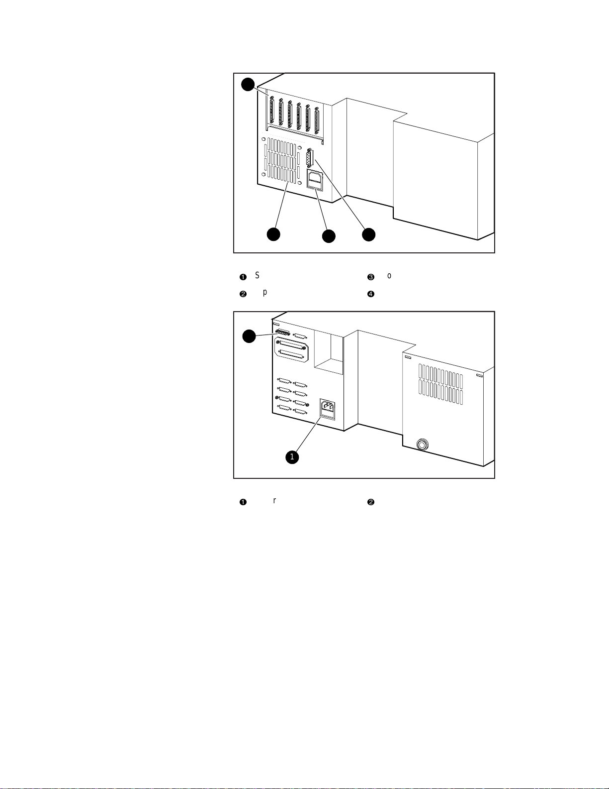
Figure 1-5. Expansion Unit Rear View ................................................................... 1-9
Figure 1-6. MiniLibrary Base Module Rear View ................................................ 1-10
Figure 1-7. Data Unit Rear View........................................................................... 1-10
Figure 2-1. Expansion Unit Front Panel.................................................................. 2-2
Figure 2-2. Expansion Unit Control Panel .............................................................. 2-3
Figure 2-3. MiniLibrary Base Module Front Panel................................................. 2-5
Figure 2-4. MiniLibrary Base Module Control Panel ............................................. 2-7
Figure 2-5.................................................................................................................. 2-8
Figure 2-6. Data Unit Front Panel ........................................................................... 2-8
Figure 2-7. Data Unit Control Panel........................................................................ 2-9
Figure 2-8. POST Screen....................................................................................... 2-11
Figure 2-9. Initialization Screen ............................................................................ 2-11
Figure 2-10. Default Screen................................................................................... 2-11
Figure 2-11. Fault Screen ...................................................................................... 2-12
Figure 2-12. MiniLibrary Base Module Default Screen........................................ 2-12
Figure 2-13. MiniLibrary Menu Structure............................................................. 2-15
Figure 2-14. Main Menu....................................................................................... 2-16
Figure 2-15. Panel Locked Screen......................................................................... 2-16
Figure 2-16. Code Entry Submenu........................................................................ 2-17
Figure 2-17. Show Status Menu ............................................................................ 2-18
Figure 2-18. Library Status Submenu.................................................................... 2-18
Figure 2-19. Drive Status Menu ............................................................................ 2-19
Figure 2-20. Map Info Submenu ........................................................................... 2-20
Figure 2-21. Security Menu................................................................................... 2-21
Figure 2-22. Code Select Submenu....................................................................... 2-21
Figure 2-23. Code Accept Submenu...................................................................... 2-22
Figure 2-24. Panel Locked Screen......................................................................... 2-22
Figure 2-25. Code Entry Submenu........................................................................ 2-22
Figure 2-26. Code Validate Submenu ................................................................... 2-23
Figure 2-27. Error History Screen......................................................................... 2-23
Figure 2-28. Default Screen................................................................................... 2-24
Figure 2-29. Main Menu........................................................................................ 2-24
Figure 2-30. Load/Unload Initial Screen............................................................... 2-24
Figure 2-31. Load/Unload ‘From‘ Entry Screen ................................................... 2-25
Figure 2-32. Load/Unload ‘To’ Entry Screen ....................................................... 2-26
Figure 2-33. Confirmation Screen......................................................................... 2-26
Figure 2-34. Load/Unload ‘In Progress’ Screen.................................................... 2-26
Figure 2-35. Magazine In Place............................................................................. 2-28
Figure 2-36.............................................................................................................. 2-28
Figure 2-37. Main Menu........................................................................................ 2-28
Figure 2-38. Main Menu, Scrolled ........................................................................ 2-29
Page 8

viii Compaq TL881 MiniLibrary System Users Guide
Figure 2-39. Security Menu....................................................................................2-29
Figure 2-40. Unlock All Media Screen ..................................................................2-29
Figure 2-41. 10-Slot Tape Magazine with Cartridges Installed.............................2-30
Figure 2-42. Main Menu.........................................................................................2-30
Figure 2-43. Main Menu, Scrolled .........................................................................2-30
Figure 2-44. Security Menu....................................................................................2-31
Figure 2-45. Unlock All Media Screen ..................................................................2-31
Figure 2-46. Lock All Media Screen......................................................................2-31
Figure 2-47. MiniLibrary Base Module Front Panel
Figure 2-48. DLT Tape Cartridge...........................................................................2-34
Figure 2-49. Expansion Unit and Data Unit Front View .......................................2-38
Figure 2-50. MiniLibrary Base Module Front View..............................................2-39
Figure 2-51. MiniLibrary Base Module 10-Cartridge Magazine...........................2-41
Figure 2-52. Expansion Unit Rear View................................................................2-41
Figure 2-53. MiniLibrary Base Module Rear View...............................................2-42
Figure 2-54. Data Unit Rear View..........................................................................2-42
Figure 3-1. Pass-Thru Mechanism External Parts
Figure 3-2. Pass-Thru Mechanism Car (Front View)...............................................3-5
Figure 3-3. Car Rear View Showing Belt Block......................................................3-6
Figure 3-4. Pass-Thru Mechanism Assembled.........................................................3-8
Figure 3-5. Threading the Belt through the Drive Section.....................................3-10
Figure 3-6. Threading the Belt through the Base Section......................................3-11
Figure 3-7. Checking Belt Length..........................................................................3-12
Figure 3-8. Belt Block With Belt In Place .............................................................3-12
Figure 3-9. Aligning the Captive Screws With the Block......................................3-13
Figure 3-10. Separating a Rack Slide.....................................................................3-16
Figure 3-11. Rack Slide Parts for Standard 19” EIA/RETMA
Rackmounting....................................................................................................3-18
Figure 3-12. Parts List for StorageWorks Metric Rackmounting ..........................3-20
Figure 3-13. Metric Rackmount Installation Layout..............................................3-23
Figure 3-14. Installing the Pass-Thru Mechanism in the Rack..............................3-24
Figure 3-15. Expansion Unit SCSI Connectors and Cables
(Fast/Wide SCSI Shown)...................................................................................3-26
Figure 3-16. MiniLibrary Base Module SCSI Connectors, Terminators and
Cables (Fast/Wide Interface, Independent Bus Connection Shown) ................3-30
Figure 3-17. MiniLibrary Base Module SCSI Connectors, Terminator,
Jumpers and Cables (SCSI-2 Interface, Daisy-chained Connection
Shown)...............................................................................................................3-31
Figure 3-18. MiniLibrary Base Module Default Screen ........................................3-32
Figure 3-19. MiniLibrary Base Module Main Menu..............................................3-32
Figure 3-20. Configure Submenu...........................................................................3-33
Figure 3-21. Configure Submenu, Scrolled............................................................3-33
Figure 3-22. Special Config Submenu ...................................................................3-33
Figure 3-23. Special Config Submenu, Scrolled....................................................3-33
Figure 3-24. Acknowledgment Screen...................................................................3-34
Figure 3-25. Default Screen....................................................................................3-34
..........................................2-32
................................................3-4
Page 9

About This Guide ix
Figure 3-26. Main Menu........................................................................................ 3-34
Figure 3-27. Configure Submenu .......................................................................... 3-35
Figure 3-28. Set SCSI Submenu............................................................................ 3-35
Figure 3-29. Set SCSI Submenu Scrolled ............................................................. 3-36
Figure 3-30. Set Mail Slot Submenu ..................................................................... 3-37
Figure 3-31. Set Mail Slot Submenu Enabled....................................................... 3-37
Figure 3-32. Set Reserved Slots Submenu ............................................................ 3-38
Figure 4-1. Default Screen....................................................................................... 4-2
Figure 4-2. Main Menu............................................................................................ 4-2
Figure 4-3. Configure Submenu .............................................................................. 4-2
Figure 4-4. Drive Selection Submenu ..................................................................... 4-3
Figure 4-5. Set Data Format Submenu .................................................................... 4-3
Figure 4-6. Main Menu............................................................................................ 4-5
Figure 4-7. Configure Submenu .............................................................................. 4-5
Figure 4-8. Library Mode Selection Menu.............................................................. 4-5
Figure 4-9. Configure Submenu .............................................................................. 4-6
Figure 4-10. Special Config Submenu..................................................................... 4-6
Figure 5-1. Main Menu............................................................................................ 5-3
Figure 5-2. Maintenance Submenu.......................................................................... 5-3
Figure 5-3. Cleaning Submenu................................................................................ 5-3
Figure 5-4. Cleaning Confirmation Screen.............................................................. 5-4
Figure 5-5. Cleaning In Progress Screen................................................................. 5-4
Figure 6-1. Troubleshooting Flow Chart................................................................. 6-3
Figure 6-2. Main Menu.......................................................................................... 6-25
Figure 6-3. Maintenance Submenu........................................................................ 6-25
Figure 6-4. Diagnostic Submenu........................................................................... 6-25
Figure D-1. Parts Location ......................................................................................D-2
Figure D-2. Removing the Skin Cover....................................................................D-3
Figure D-3. Removing the Cover Plate ...................................................................D-5
Figure D-4. Drive Caddy.........................................................................................D-6
Figure E-1. Cover Assembly Side Plate ..................................................................E-2
Figure E-2. Mechanism Section Cover................................................................... E-2
Figure F-1. Opening the cartridge door................................................................... F-3
Figure F-2. Correct and incorrect cartridge (takeup) leader positions .................... F-4
Figure F-3. Applying a bar code label..................................................................... F-9
Figure F-4. Write-protecting a cartridge................................................................ F-10
Figure F-5. Tape Drive Control Panel................................................................... F-11
List of Tables
Table 1-1 MiniLibrary system Tape Capacity........................................................ 1-11
Table 2-1 Control Panel Button Functions............................................................... 2-4
Table 3-1 Belt Length for Various System Sizes ................................................... 3-10
Table 3-2 MiniLibrary Configuration Options....................................................... 3-41
Table 3-3 MiniLibrary Special Configuration Options.......................................... 3-46
Table 4-1 MiniLibrary Configuration Options......................................................... 4-8
Page 10

x Compaq TL881 MiniLibrary System Users Guide
Table 4-2 MiniLibrary Special Configuration Options...........................................4-12
Table 4-3 MiniLibrary Special Configuration Options...........................................4-13
Table 6-1 Error Recovery Procedures.......................................................................6-4
Table 6-2 Fault Symptom Codes...............................................................................6-5
Table A-1 Operational Performance Specifications.................................................A-1
Table A-2 Reliability Specifications (Drives)..........................................................A-2
Table A-3 Power Specifications...............................................................................A-2
Table A-4 Reliability Specifications (Library Robotics) .........................................A-3
Table A-4 Mechanical Specifications.......................................................................A-3
Table A-5 Mechanical Specifications.......................................................................A-3
Table A-7 Environmental Specifications (Operating)..............................................A-4
Table A-7 Environmental Specifications (Packed or Unpacked) ............................A-4
Table A-7 Environmental Specifications (Storage/Transit).....................................A-4
Table A-7 Acoustic Emission Level.........................................................................A-5
Table A-11 Regulatory Agency Product Safety Certifications................................A-5
Table A-11 Regulatory Agency Product Safety Certifications................................A-7
Table A-11 Regulatory Agency Product Safety Certifications................................A-7
Table B-1 Compaq Tape Data or Cleaning Cartridges Part Numbers .....................B-1
Table B-1 Bar Code Label and Magazine Part Numbers.........................................B-2
Table F-1 Cartridge Environmental Guidelines ....................................................... F-5
Table F-2 Cleaning Cartridge Guidelines................................................................. F-7
Table F-3 Tape Drive Control Panel ...................................................................... F-12
Page 11

This guide is designed to be used as step-by-step instructions for installation
and as a reference for operation, troubleshooting, and future upgrades.
Text Conventions
This document uses the following conventions to distinguish elements of text:
Keys Keys appear in boldface. A plus sign (+) between
USER INPUT User input appears in a different typeface and in
FILENAMES File names appear in uppercase italics.
About This Guide
two keys indicates that they should be pressed
simultaneously.
uppercase.
Menu Options,
Command Names,
Dialog Box Names
COMMANDS,
DIRECTORY NAMES,
and DRIVE NAMES
Type When you are instructed to type information, type
Enter When you are instructed to enter information, type
These elements appear in initial capital letters.
These elements appear in uppercase.
the information without pressing the Enter key.
the information and then press the Enter key.
Page 12
xii Compaq TL881 MiniLibrary System Users Guide
Symbols in Text
These symbols may be found in the text of this guide. They have the following
meanings.
WARNING: Text set off in this manner indicates that failure to follow directions
in the warning could result in bodily harm or loss of life.
CAUTION: Text set off in this manner indicates that failure to follow directions
could result in damage to equipment or loss of information.
IMPORTANT: Text set off in this manner presents clarifying information or specific
instructions.
NOTE: Text set off in this manner presents commentary, sidelights, or interesting points
of information.
Symbols on Equipment
These icons may be located on equipment in areas where hazardous conditions
may exist.
Any surface or area of the equipment marked with these symbols
indicates the presence of electrical shock hazards. Enclosed area
contains no operator serviceable parts.
WARNING: To reduce the risk of injury from electrical shock hazards,
do not open this enclosure.
Any RJ-45 receptacle marked with these symbols indicates a Network
Interface Connection.
WARNING: To reduce the risk of electrical shock, fire, or damage to
the equipment, do not plug telephone or telecommunications
connectors into this receptacle.
Page 13
Rack Stability
About This Guide xiii
Any surface or area of the equipment marked with these symbols
indicates the presence of a hot surface or hot component. If this
surface is contacted, the potential for injury exists.
WARNING: To reduce the risk of injury from a hot component, allow
the surface to cool before touching.
Power Supplies or Systems marked with these symbols
indicate the equipment is supplied by multiple sources of
power.
WARNING: To reduce the risk of injury from electrical shock,
remove all power cords to completely disconnect power from
the system.
WARNING: To reduce the risk of personal injury or damage to the equipment,
be sure that:
■
The leveling jacks are extended to the floor.
■
The full weight of the rack rests on the leveling jacks.
■
The stabilizing feet are attached to the rack if it is a single rack
installations.
■
The racks are coupled together in multiple rack installations.
■
A rack may become unstable if more than one component is extended for
any reason. Extend only one component at a time.
Getting Help
If you have a problem and have exhausted the information in this guide, you
can get further information and other help in the following locations.
Compaq Technical Support
You are entitled to free hardware technical telephone support for your product
for as long you own the product. A technical support specialist will help you
diagnose the problem or guide you to the next step in the warranty process.
Page 14

xiv Compaq TL881 MiniLibrary System Users Guide
In North America, call the Compaq Technical Phone Support Center at
1-800-OK-COMPAQ
Outside North America, call the nearest Compaq Technical Support Phone
Center. Telephone numbers for world wide Technical Support Centers are
listed on the Compaq website. Access the Compaq website by logging on to
the Internet at http://www.compaq.com.
Be sure to have the following information available before you call Compaq:
■
Technical support registration number (if applicable)
■
Product serial number (s)
■
Product model name(s) and numbers(s)
■
Applicable error messages
■
Add-on boards or hardware
■
Third-party hardware or software
■
Operating system type and revision level
■
Detailed, specific questions
Compaq Website
1
. This service is available 24 hours a day, 7 days a week.
The Compaq website has information on this product as well as the latest
drivers and Flash ROM images. You can access the Compaq website by
logging on to the Internet at http://www.compaq.com.
Compaq Authorized Reseller
For the name of your nearest Compaq Authorized Reseller:
■
In the United States, call 1-800-345-1518.
■
In Canada, call 1-800-263-5868.
■
Elsewhere, see the Compaq website for locations and telephone
numbers.
1
For continuous quality improvement, calls may be recorded or monitored.
Page 15

The TL881 MiniLibrary
This chapter describes the features of the MiniLibrary Expansion Unit, the
MiniLibrary Base Module, and the MiniLibrary Data Unit of the MiniLibrary
system, including storage architecture, SCSI interface, bus performance, and
physical configuration/expansion options.
The MiniLibrary system is an expandable, modular tape library system that
combines DLT technology drive with advanced robotics. The MiniLibrary
system is designed for high duty-cycle on-line and near-on-line applications,
such as hierarchical storage management (HSM). It is a superior performer in
high-volume backup and archival service as well.
Chapter
1
Introduction
Modules
The MiniLibrary system is based on three types of modules:
n Expansion Unit (Master)
n MiniLibrary Base Module
n Data Unit
The MiniLibrary system consists of one Expansion Unit and up to five
MiniLibrary Base Modules and Data Units in combination stacked in a rack.
The Expansion Unit can move media freely between itself, the MiniLibrary
Base Module, and the Data Unit by way of the system’s robotically controlled
Pass-Thru Mechanism.
Page 16

1-2 Compaq TL881 Minilibrary System Users Guide
In a MiniLibrary system, you can combine modules to provide the right
combination of capacity and performance to meet your present storage
requirements. Compaq’s MiniLibrary storage architecture lets you add
modules to optimize throughput and capacity as your needs change.
MiniLibrary Storage Architecture
When connected as a system, the robotics in the Expansion Unit act as
commanded by the host computer(s). The host(s) need no knowledge of the
internal geometry of the system, or of the actions or capabilities of the
MiniLibrary Base Modules or Data Units.
The Expansion Unit presents to the host(s) a single SCSI medium changer
device with a single SCSI Medium Transport element, several SCSI Storage
elements equal to the total number of cartridge magazine slots, a number of
SCSI Import/Export elements as specified by the user during configuration of
the Expansion Unit, and a number of SCSI Data Transfer elements equal to the
total number of drives in the system.
Flexibility
Compaq’s MiniLibrary storage architecture is uniquely suited to growing
storage needs. Its flexible library robotics system enables you to start with a
system configured to your present requirements, confident that as your storage
needs evolve, you can easily modify the MiniLibrary by adding modules and
extending the Pass-Thru Mechanism. Add drives for faster performance or
magazine space for greater capacity, as needed. Then just turn on the power,
and immediately the system updates the system map so the host is informed of
the expanded capability.
The Expansion Unit
The Expansion Unit (Figure 1–1) integrates the robotics in the individual
modules into a single, coordinated library robotics system. The Expansion
Unit performs and maintains an inventory of all media present in the system,
including bar code data. All necessary system control operations may be
performed from the control panel of the Expansion Unit, as well as from the
host via software. The SCSI interface for the library robotics is designed for
high-speed communication with the host, and Fast/Wide SCSI configurations.
Page 17
Introduction 1-3
1
2
3
4
5
6
SHR-1194
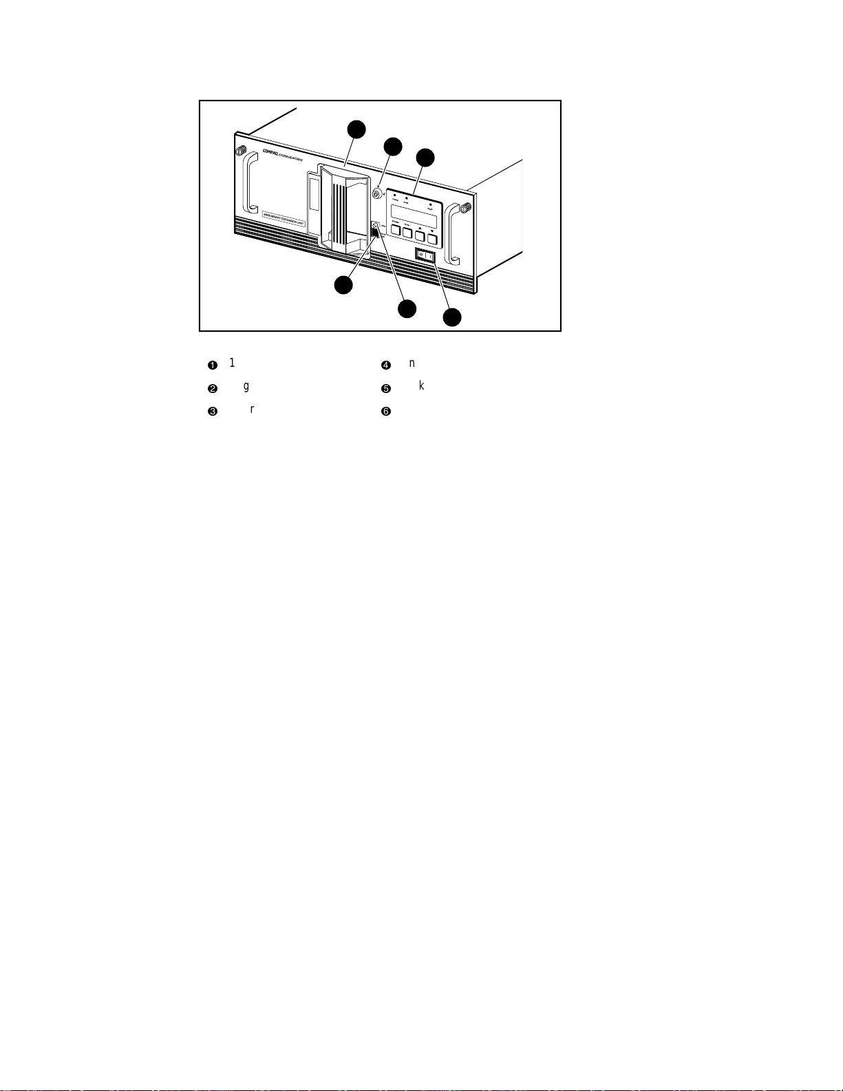
Figure 1-1. Expansion Unit Front View
16-Cartridge magazine
1
Magazine security lock
2
Control panel
3
Unlock /Open button
4
Locked indicator
5
Power switch
6
In addition to its system control functions, the Expansion Unit has a 16cartridge magazine with a rugged random access robotic mechanism. The
module robotics moves cartridges between the Pass-Thru Mechanism and any
of the 16 cartridge storage locations.
The user may designate a magazine in one of the MiniLibrary Base Modules
as a mail slot for inserting or removing one or more single cartridges, which
implements the SCSI Import/Export commands.
NOTE: A magazine that has been reserved for Import/Export service may not be used for
data storage.
Page 18

1-4 Compaq TL881 Minilibrary System Users Guide
The MiniLibrary Base Module
The MiniLibrary Base Module (Figure 1–2) has one or two DLT 20/40 tape
drives and a 10-cartridge magazine with a rugged random access robotic
mechanism. The TL881 using one or two DLT20/40 series drives, also uses
the DLTtape IV cartridges, which provide a native capacity of 20 GB per
cartridge. All models can also read and write DLTtape III and DLT tape IIIxt
cartridges. Both read and write densities are selectable from the front panel,
and under SCSI control from the host. These units are available as differential
rack-mount or table-top versions, as well as a single-ended table-top-only
version.
1
2
3
U
s
e
C
le
Drive
a
n
e
r
L
Fault
o
a
d
e
r
F
a
u
lt
4
5
Figure 1-2. MiniLibrary Base Module Front View
10-Cartridge magazine
1
Magazine security lock
2
Control panel
3
Unlock/Open button
4
Locked indicator
5
Power switch
6
6
SHR-1195
Page 19

The Data Unit
The Data Unit (Figure 1–3) has a 16-cartridge magazine, a random access
robotic mechanism, and no tape drives. The module robotics, under control of
the Expansion Unit, moves cartridges between the Pass-Thru Mechanism and
any of the 16 cartridge storage locations.
Introduction 1-5
1
2
3
4
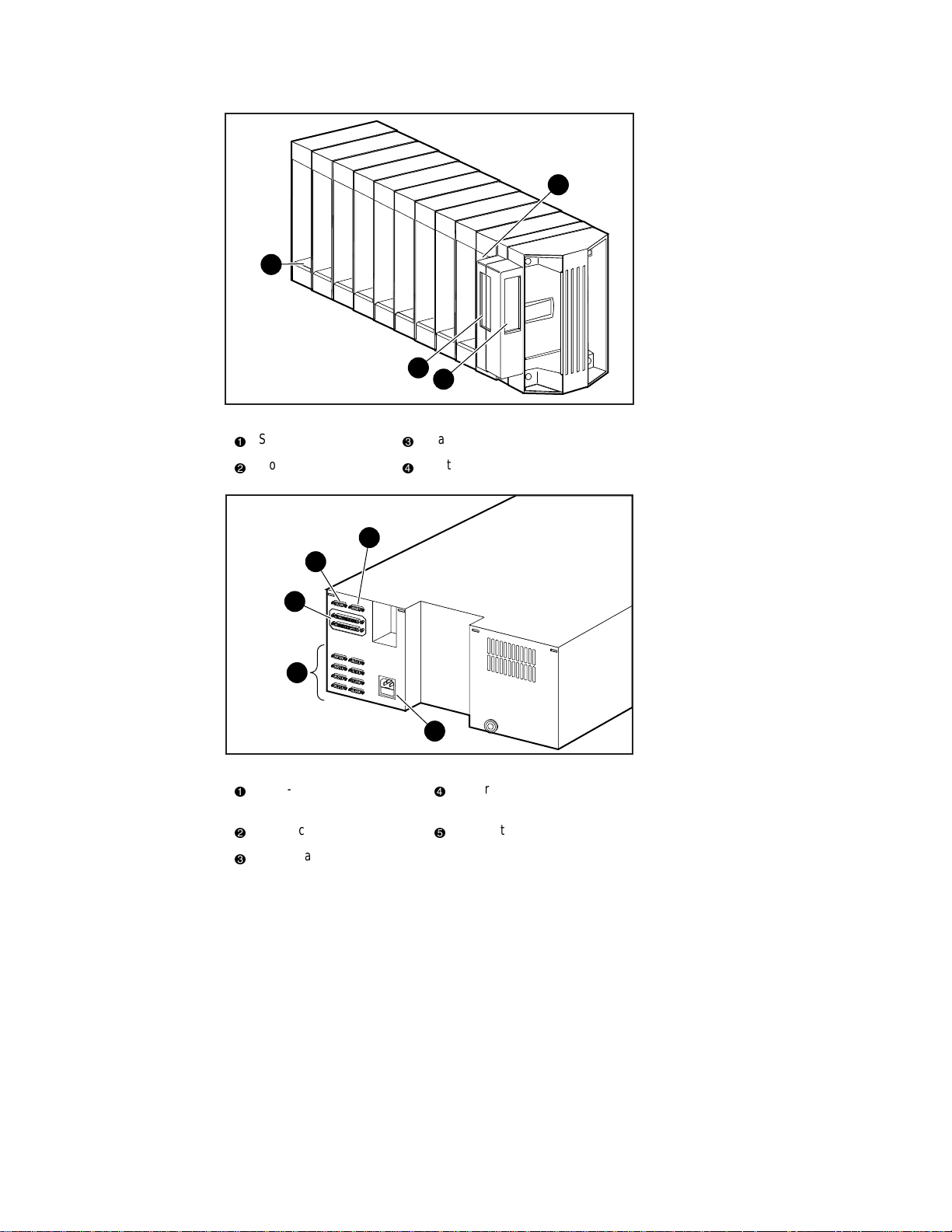
Figure 1-3. Data Unit Front View
16-Cartridge magazine
1
Magazine security lock
2
Control panel
3
4
5
6
SCSI Interface Configurations
Systems are equipped with DLT 20/40 drives use a narrow SCSI interface
using high-density 68-pin D-series connectors. The section on SCSI Interfaces
in Chapter 3, Installation, describes the available interface options.
SCSI Bus Performance Considerations
Data Transfer Rate
The data transfer rate of the MiniLibrary is dependent on the type and number
of drives and on the SCSI bus configuration. The bandwidth of the SCSI bus is
limited. As a result, the transfer rate of drives such as the DLT20/40 can be
limited by sharing a SCSI bus with another disc drive on tape. It is
recommended that the MiniLibrary be installed on its own controller for
optimum performance.
5
Unlock /Open button
Locked indicator
Power switch
6
SHR-1194
Page 20

1-6 Compaq TL881 Minilibrary System Users Guide
Drives
With a standard SCSI interface, modules equipped with DLT 20/40 drives
have a native data transfer rate of 1.5 MB/second, 3.0 MB/sec for two drives.
The rates for compressed data are dependent on compression ratio, record size,
data type, and other system parameters, but averages approximately 1:7.
Internal Cabling Configuration
The differential version of the MiniLibrary base module is wired in an
independent-bus SCSI configuration. That is, the robotics and each of the
drives has its own SCSI bus. SCSI jumpers are available for those applications
requiring that some combination of drives and robotics be daisy-chained to a
single SCSI bus. The single-ended table-top version, however, has the first
driver daisy-chained internally to the robotics in order to reduce cable length.
These configurations are described in more detail in the section on SCSI
Interfaces in Chapter 3, Installation.
Physical Configuration
The Expansion Unit must be mounted at the top of the stack, which places its
control panel at a convenient height. The control panels of the MiniLibrary
Base Modules and Data Units are of secondary importance, as they serve
mainly to help localize system failures. When installed, the motor drive
assembly of the Pass-Thru Mechanism is directly behind the Expansion Unit.
MiniLibrary Base Modules may be installed anywhere below the Expansion
Unit, in any order. There may be a slight performance advantage in making the
MiniLibrary Base Modules contiguous, but gaps are permitted. The size of a
gap is limited by the fact that each gap must be bridged by some number of 7"
Pass-Thru Mechanism track sections. For safety, available cover plates should
be installed on all Pass-Thru Mechanism sections that are not connected to
MiniLibrary modules.
The Expansion Unit senses the position of each module during initialization at
power-up. Even if there are gaps between modules, the system will operate
correctly. If you plan to leave gaps between modules, be sure to order
additional Pass-Thru Mechanism track segments and cover plates equal to the
length of the gap.
System Expansion
A MiniLibrary system may be expanded in capacity and performance by
adding or removing TL881 modules. Associated with the Expansion Unit and
each MiniLibrary Base Module is a section of the Pass-Thru Mechanism.
Page 21

Features
Introduction 1-7
System firmware integrates all of the robotics of these system modules with
that of the Pass-Thru Mechanism into a single high-performance library
robotics system.
There are a number of important external features to note about the Expansion
Unit, the MiniLibrary Base Module and the Data Unit. See Figures 1–1
through 1–7 to locate the features described here.
Control Panel
The control panels for all modules are the same, except for the number of LED
indicators. The control panel features a 4-line by 20-character backlit LCD
display, three or four LED indicators, and four buttons. The buttons enable the
operator to navigate through the menu structure to select and display operating
modes, device status, diagnostic and maintenance functions, device history and
error statistics, and system configuration. The functions of the control panel
are described in detail in Chapter 2, Operation.
Display
The backlit 4-line by 20-character control panel display provides a highly
intelligible presentation of drive and loader status, menu choices and error
messages. The scrolling feature greatly expands the amount of information
available to the operator. In the Expansion Unit, status information is available
for the entire system. The MiniLibrary Base Modules display other
information as needed for localizing malfunctions.
Magazine Security Lock
The Magazine Security Lock is a key-operated switch on the front panel of
each module. It can be used to prevent inadvertent removal of the cartridge
magazine.
Power Supply
The AC Power switch is located on the front panel of the module. The
autoranging power supply will adjust automatically to either of two operating
voltage ranges. The ranges are 100-120 VAC and 200-240 VAC. The power
supply is capable of operating at 50 or 60 Hz without any adjustment or
modification. AC power is supplied to the power supply by a single IECcompatible socket that can be connected to any properly grounded outlet.
Page 22

1-8 Compaq TL881 Minilibrary System Users Guide
Tape Cartridge Magazines
The 10-cartridge and 16-cartridge magazines are removable from the front
panel, but may be protected from tampering by any of three means: 1) a keyoperated Magazine Security Lock which must be unlocked before the
magazine can be removed, 2) an electronic combination lock operated by
using buttons on the Expansion Unit control panel, and 3) issuance by the host
of a SCSI ‘Prevent Medium Removal’ command. The rugged carbon-fiberreinforced polymer magazine fits into an extruded track, which assures precise
positioning with respect to the library robotics. A 10-cartridge tape magazine
is shown in Figure 1–4. Insertion and removal of the magazine is described in
Chapter 2, Operation.
Integral Fan Cooling
A single forced-air fan is mounted inside each module to provide optimum
cooling for critical parts, and to prevent the drive and robotics electronics,
motors and power supply from overheating.
Library Robotics
The MiniLibrary system features library robotics that can load any of the
cartridges stored in any magazine in the system into any of the tape drives,
moving cartridges among as many as six modules within the MiniLibrary
system.
Bar Code Reader
The bar code reader is mounted on the cartridge shuttle in each module. It
reads bar code labels attached to each cartridge, and maintains the bar code
data in memory as part of the library System Map.
Page 23
4
3
2
Figure 1-4. MiniLibrary Base Module 10-Cartridge Magazine
Slot 0
1
Front label slide slot
2
Barcode label slide slot (not used)
3
Slot 9
4
Introduction 1-9
1
SHR-1226
1
5
4
3
2
Figure 1-5. Expansion Unit Rear View
Pass-Thru Mechanism
1
4
motor drive
Power connector
2
MiniLibrary Base Module robotics interface connectors
3
5
SHR-1227
Library robotics SCSI interface
Diagnostics connector
Page 24
1-10 Compaq TL881 Minilibrary System Users Guide
1
4
3
2
Figure 1-6. MiniLibrary Base Module Rear View
SCSI interface
1
Expansion Unit interface
2
2
1
3
4
Figure 1-7. Data Unit Rear View
Power connector
1
2
SHR-1228
Power connector
Fan
SHR-1321
Flash connector
Page 25

Advanced Design Features
The MiniLibrary system incorporates many significant improvements in tape
drive and library design. One of the most important is the use of highly
reliable DLT technology, with media rated by the media manufacturer at better
than 1,000,000 head passes.
Embedded Diagnostics
The MiniLibrary system and each of its modules provide three levels of
embedded diagnostics. The Power-On Self Test (POST) performs various
verification tests on the system’s configuration and host interface and device
control functions, as well as memory tests, at power-up. The second level of
diagnostics is the User Diagnostics, which provide for displaying and
changing configuration options. The third level, Customer Engineer (CE)
Diagnostics, include advanced diagnostics to be used by Customer Engineers
for servicing the MiniLibrary system. Both the User Diagnostics and the CE
Diagnostics may be selected from the front panel.
User Diagnostics are described in greater detail in Chapter 3, Installation.
Error Checking
Introduction 1-11
Drives used in the MiniLibrary system apply a 16-bit parity check to each
record, a 64-bit CRC to each 4 kb of data, and Reed-Solomon error correction
code overall. In addition, there is an internal parity check on the data buffer.
Compression
MiniLibrary system drives use the standard Digital Lempel-Ziv (DLZ) data
compression algorithm.
Capacity
A MiniLibrary Base Module with its 10-cartridge magazine and a single
Expansion Unit with its 16-cartridge magazine offers the formatted capacities
shown in Table 1-1.
Page 26

1-12 Compaq TL881 Minilibrary System Users Guide
MiniLibrary system Tape Capacity
Table 1-1
MODEL CARTRIDGE MAGAZINE
CAPACITY
TL881 DLTtape IV 10 200 GB 400 GB
Expansion Unit DLTtape IV 16 320 GB 640 GB
Data Unit DLT Tape V 16 320 GB 640 GB
FULL MAGAZINE
UNCOMPRESSED
FULL MAGAZINE
COMPRESSED @
2:1
Media Life
The media used in the MiniLibrary is rated by the media manufacturer at over
1,000,000 head passes, and a shelf life of at least 30 years.
Page 27

Operation Overview
This chapter describes manual operation of the MiniLibrary system. The
system is operated manually through the MiniLibrary Expansion Unit control
panel. Online and offline operations can be done through the control panels of
the MiniLibrary Base Module and the MiniLibrary Data Unit.
Expansion Unit
Chapter
2
Operation
Figure 2-1 shows the front panel of the Expansion Unit. The panel includes a
power switch and the Control Panel, which has pushbuttons, LED indicators,
and a display.
Power Switch
The power switch controls the supply of AC power to the unit. The switch is
recessed into the front panel to prevent accidental power-up or power-down.
Press 1 to turn the unit on and press 0 to turn the unit off.
NOTE: The Expansion Unit must be turned on after or simultaneously with the other
modules. If this is not done, the Expansion Unit may not be notified of the presence of one
or more of the other modules.
Page 28

2-2 Compaq TL881 Minilibrary System Users Guide
1
2
3
4
Figure 2-1. Expansion Unit Front Panel
16-Cartridge magazine
1
Magazine security lock
2
Control panel
3
5
Unlock/Open button
4
Locked indicator
5
Power switch
6
6
SHR-1194
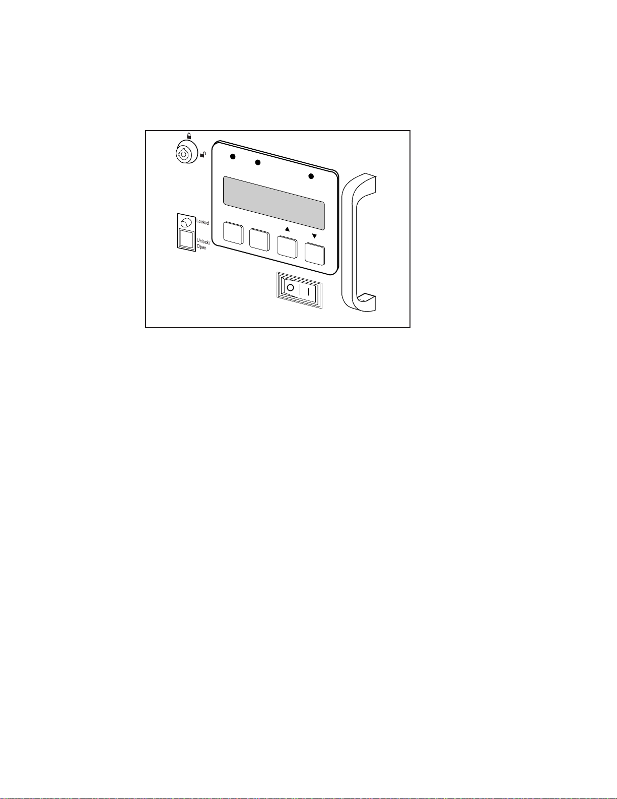
Control Panel
The Expansion Unit Control Panel (Figure 2–2) contains three LED indicators,
a four-line by 20–character backlit LCD display, and four pushbuttons. The
pushbuttons enable the operator to navigate through the menu structure to
select and display operating modes, device status, diagnostic and maintenance
functions, device history and error statistics, and system configuration.
LED Indicators
The three LED indicators on the Control Panel are labeled
Alert (yellow), and Fault (red).
■
Ready (green) - lights when the system is ready to accept commands,
either from the Control Panel or from the host computer. The
indicator goes out when you enter the Menu Mode.
■
Alert (yellow) - indicates that a fault or some other matter that requires
attention has occurred in one of the modules in the system. Line 2 of the
display blinks the number of the module where the fault has occurred.
The Control Panel of the indicated module may give a further indication
of the cause of the alert. Often, when the
Alert LED is lit, a Fault LED
is lighted on one or more of the MiniLibrary Base Modules as well.
Ready (green),
Ready
Page 29

■
Fault (red) - indicates that a fault has occurred in the Expansion Unit, or
that the magazine door is unable to close. When the Fault LED is
lighted, a Fault Screen appears on the LCD display. The Fault Screen is
described later in this chapter. A list of fault symptom codes (FSC) and
error recovery procedures (ERP) appears in Chapter 6, Diagnostics and
Troubleshooting.
R
eady
A
lert
Fault
Escape
Enter
Operation 2-3
SHR-1229
Figure 2-2. Expansion Unit Control Panel
Pushbuttons
There are four buttons on the control panel, labeled
Escape, Enter, , and
The buttons do not directly control specific functions or options. Instead, you
use the buttons to navigate from the Default Screen through a multi-level
menu structure, then select the desired option from the appropriate menu using
Enter button. Table 2-1 describes the effect of each of the four buttons
the
under various conditions.
The three most important things you need to know about the buttons are:
1. To enter the Menu Mode and display the Main Menu from the Default
Screen, press the
2. To return to the Main Menu from a submenu, press the
repeatedly until the Main Menu appears. Pressing the
Enter button.
Escape button
Escape button
while the Main Menu is displayed exits the Menu Mode and returns you
to the Default Screen. The Default Screen and the Main Menu are
shown later in this chapter.
Page 30

2-4 Compaq TL881 Minilibrary System Users Guide
3. To display the Show Status Menu only without entering the Menu
Mode, press the
Escape button at the Default Screen. The system
remains online.
NOTE: When you enter the Menu Mode at the Expansion Unit, the Ready light on that
module goes out. This means that the MiniLibrary system of
responds to all commands from the host with a SCSI Not Ready until you exit the Menu
Mode and the Ready light goes on. When you enter the Menu Mode at any of the
MiniLibrary Base Modules, the Ready light on that module goes out. This means that the
individual module
pertaining to that module with a SCSI Not Ready until you exit the Menu Mode and the
Ready light goes on.
Screen Escape Enter s Note 1 t Note 1
is
off-line
off-line
, and the system
, and the system responds to all commands from the host
Table 2-1
Control Panel Button Functions
At POST
N/A – Note 2 N/A N/A – Note 3 N/A – Note 3
Screen
At Default
Screen
Displays Show
Status
Submenu
At Status
Submenu
Returns to
Default Screen
(while online)
In Menu Mode Rejects
currently
Displayed
Choice, or
Aborts Control
Panel
Operation In
Progress, or
Exits to Next
Higher Menu
Level, or
Exits Menu
Mode to
Default Screen
Enters Menu
Mode
Same as in
Menu Mode
Accepts
Currently
displayed
Choice
N/A N/A
Same as in
Menu Mode
Moves
One Line
Upward
Through List
of Options,
or
Scrolls Part
of Display 1
Line Toward
Top of List of
Options
Same as in
Menu Mode
Moves
One Line
Downward
through List
of Options,
or
Scrolls Part
of Display 1
Line Toward
Bottom of
List of
Options
continued
Page 31
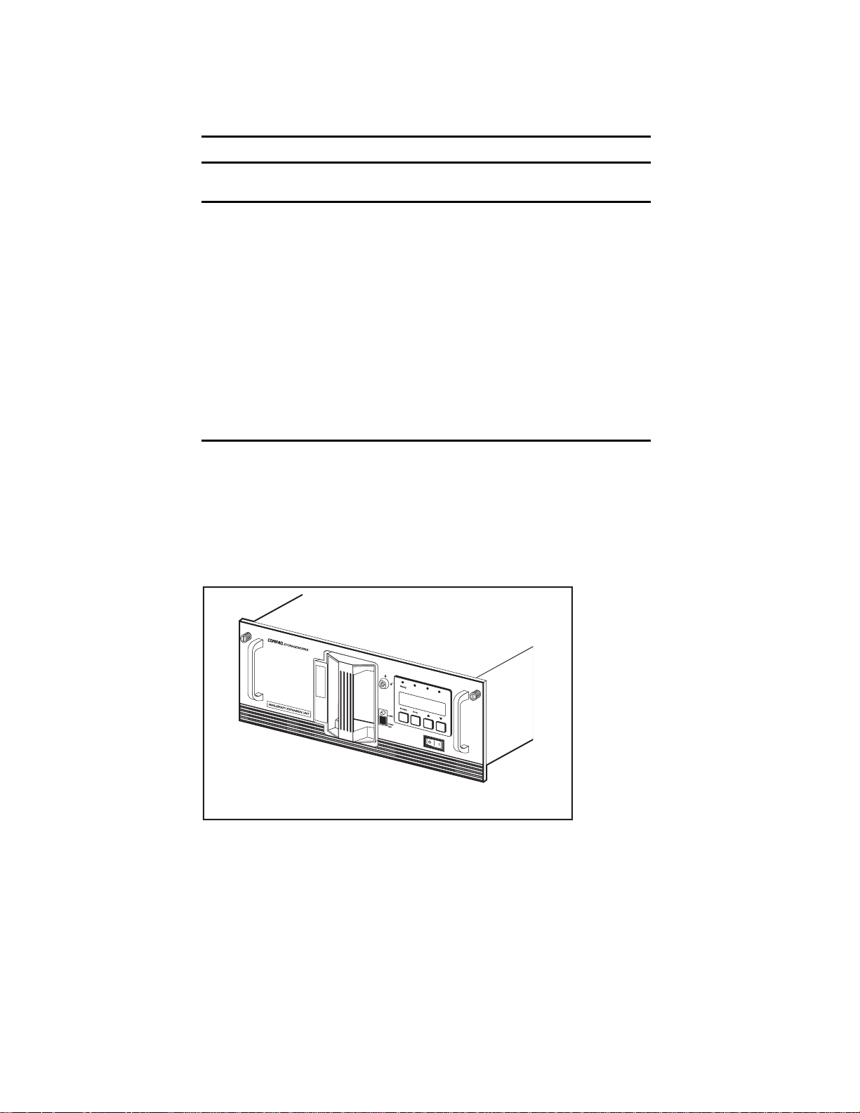
Table 2-1
Control Panel Button Functions
Screen Escape Enter s Note 1 t Note 1
continued
Operation 2-5
At Fault
Screen
Notes:
1 There is an auto-repeat feature for the s and t buttons. When the user presses either
button for more than one-half second, the control panel behaves as if the user were
pressing and releasing the button about four times per second. This effect stops when the
user releases the button.
2 This button is sampled during power-up while all control panel LEDs are on. If it is
depressed during that time, the system updates its geometry; that is, it checks for the
presence and location of all modules and remaps all media. Use this method when
removing or installing a module permanently.
3 These buttons are sampled during power-up. If
system clears low-power memory. Use this procedure only when low-power data is
corrupted. Clearing low-power memory erases all log information, such as configuration
history, error history, and statistics. In addition, the system time, date and password
information is erased and must be re-entered.
MiniLibrary Base Module
Figure 2–3 shows the front panel of the MiniLibrary Base Module. The panel
includes a power switch and the Control Panel, which has pushbuttons, LED
indicators, and a display.
N/A Clears Soft
Errors
N/A N/A
both
are depressed during that time, the
U
se
C
leaner
Figure 2-3. MiniLibrary Base Module Front Panel
D
r
iv
e
L
F
oad
a
u
er
lt
F
au
lt
SHR-1195
Page 32

2-6 Compaq TL881 Minilibrary System Users Guide
Power Switch
The power switch controls the supply of AC power to the module. The switch
is recessed into the front panel to prevent accidental power-up or power-down.
Press 1 to turn the module on and press 0 to turn the module off.
Control Panel
The Base Module Control Panel (Figure 2–4) contains four LED indicators, a
four–line by 20–character backlit LCD display, and four pushbuttons.
LED Indicators
The four LED indicators on the Control Panel are labeled Ready (green), Use
Cleaner (yellow), Drive Fault (red), and Loader Fault (red).
■
Ready (green) – lights when the Base Module is ready to accept
commands, either from the Control Panel or from the host computer via
the Expansion Unit. The Ready indicator goes out when you enter the
Menu Mode.
■
Use Cleaner (yellow) – indicates that either or both drives require
cleaning. A cleaning operation should be done as described in Chapter
5, Regular Maintenance. When the Use Cleaner LED comes on, you
can find out which drive needs cleaning by selecting Cleaning Needed
on the Drive status submenu.
■
Drive Fault or Loader Fault (red) – lights when a Fault Screen appears
on the LCD display. The Fault Screen is described later in this chapter.
A list of Fault Symptom Codes (FSC) and Error Recovery Procedures
(ERP) appears in Chapter 5, Regular Maintenance.
Page 33

Operation 2-7
Ready
Use
Cleaner
Drive
Loader
Fault
Fault
Escape
Enter
SHR-1248
Figure 2-4. MiniLibrary Base Module Control Panel
Pushbuttons
The pushbuttons on the Base Module Control Panel operate the same way as
the pushbuttons on the Expansion Unit Control Panel; refer to the description
of the pushbuttons for the Expansion Unit.
Data Unit
Figure 2–5 shows the front panel of the Data Unit. The panel includes a power
switch and the Control Panel, which has pushbuttons, LED indicators, and a
display.
Power Switch
The power switch controls the supply of AC power to the unit. The switch is
recessed into the front panel to prevent accidental power-up or power-down.
Press 1 to turn the unit on, and press 0 to turn the unit off.
Page 34

2-8 Compaq TL881 Minilibrary System Users Guide
1
2
3
4
Figure 2-5.
16–Cartridge magazine
1
Magazine security lock
2
Control panel
3
Figure 2-6. Data Unit Front Panel
5
Unlock/Open button
4
Locked indicator
5
Power switch.
6
6
SHR-1194
Page 35
Operation 2-9
Control Panel
The Data Unit Control Panel (Figure 2–6) contains three LED indicators, a
four–line by 20–character backlit LCD display, and four pushbuttons.
Ready
Alert
Fault
Escape
Enter
SHR-1229
Figure 2-7. Data Unit Control Panel
LED Indicators
The three LED indicators on the Control Panel are labeled Ready (green),
Alert (yellow), and Fault (red).
Ready (green) - lights when the system is ready to accept commands, either
from the Control Panel or from the host computer via the Expansion Unit. The
Ready indicator goes out when you enter the Menu Mode.
Alert (yellow) - this LED has no function in the Data Unit.
Fault (red) – when this LED lights, a Fault Screen appears in the display. The
Fault Screen is described later in this chapter. A list of Fault Sympton Codes
(FSC) and Error Recovery Procedures (ERP) appears in Chapter 5 –
Troubleshooting.
Pushbuttons
The pushbuttons on the Data Unit Control Panel operate the same way as the
pushbuttons on the Expansion Unit Control Panel; refer to the description of
the pushbuttons for the Expansion Unit.
Page 36

2-10 Compaq TL881 Minilibrary System Users Guide
Front Panel and Media Locks
To avoid accidental interruption of system operation by entering the Menu
Mode or removing cartridges while the host is accessing the system, the front
panel and the media for each module may be electronically locked. When the
front panel of the Expansion Unit is locked, you can only enter the Menu
Mode after entering a 4-digit code. That is, when the Default Screen is
displayed, pressing the
enter the code. The front panel of a MiniLibrary Base Module or a Data Unit
cannot be unlocked without using the Security submenu on the Expansion Unit
to unlock it.
All MiniLibrary Base Module and Data Unit front panels are locked by default
when connected to a Expansion Unit.
Media located in any or all modules may be locked and unlocked using the
Security submenu on the Expansion Unit. When the media are locked, you can
only remove media after unlocking the module from the Expansion Unit using
the Security submenu.
Procedures for locking and unlocking front panels and media are described
later in this chapter.
Enter button does not invoke the Menu Mode until you
Starting the System
NOTE: When powering up the MiniLibrary, power
either simultaneously with or after the other modules. If the Expansion Unit is powered on
first, its inventory of modules may be incorrect, and the contents of some or all of the
modules will be inaccessible to the system and to the host.
Display Messages
The display on the control panel is capable of displaying four lines of 20
characters each, to allow the use of easy-to-understand messages. Many of
these messages and their functions are described in this chapter. Those
displays that are described in other chapters are cross-referenced here as well.
Power-On Self Test Screen
When power is first applied to the module, a series of power-on self test
(POST) diagnostics are performed. During POST execution, the model
number of the module, the firmware revision, the status or result of the test in
progress and the current date and time are displayed on the control panel as
shown in Figure 2–7:
must
be applied to the Expansion Unit
Page 37

Operation 2-11
SHR-1343
Figure 2-8. POST Screen
Initialization Screens
After the POST is completed, the library robotics system is initialized. A series
of screens similar to similar to Figure 2–8 is displayed during this process:
SHR-1344
Figure 2-9. Initialization Screen
Default Screen
After the POST diagnostics have concluded successfully and initialization is
complete, the system Default Screen for the Expansion Unit appears (Figure
2-9):
SHR-1446
Figure 2-10. Default Screen
The numbers on the second line correspond to the MiniLibrary Base Modules
and Data Units that are connected to the system. Up to five MiniLibrary Base
Modules and Data Units may be connected. The third and fourth lines
represent the cartridge magazine in the Expansion Unit.
A rectangle will appear in each position that contains a cartridge. An underline
represents an empty slot.
Page 38

2-12 Compaq TL881 Minilibrary System Users Guide
Fault Screen
When a fault is detected within the Expansion Unit or the Pass-Thru
Mechanism, a screen similar to Figure 2–10 appears.
When a fault is detected in one of the MiniLibrary Base Modules, the Alert
LED on the Expansion Unit control panel comes on. The Fault Screen appears
on the malfunctioning MiniLibrary Base Module. At the same time, either the
Drive Fault or the Loader Fault LED is illuminated on that module.
Figure 2-11. Fault Screen
The first line in Figure 2–10 shows a numerical fault symptom code (FSC).
The second line shows a brief description of the error, in place of the words,
‘Error Description'. The third and fourth lines will contain a one- or two-line
message describing the initial error recovery procedure (ERP) in place of the
words shown in the Fault Screen.
SHR-1345
A list of the fault symptom codes (FSC) and error recovery procedures (ERP)
appears in Chapter 6, Diagnostics and Troubleshooting.
MiniLibrary Base Module Default Screen
The MiniLibrary Base Modules display a different Default Screen, as shown in
Figure 2–11:
SHR-1447
Figure 2-12. MiniLibrary Base Module Default Screen
The example shows a MiniLibrary Base Module in the module 1 position. The
first and second lines of the Default Screen show the status of the two drives
within the MiniLibrary Base Module. On line 4, a rectangle appears in each
position that contains a cartridge. An underline would appear at each empty
Page 39

Operation 2-13
slot. The numbers at the beginning and end of line 4 represent the numbers the
system has assigned to the first and last slots of that module.
The status conditions of the drives include:
■
No Tape ■ Cleaning
■
Idle ■ Unloaded
■
Rewinding ■ Loading
■
Seeking ■ Unloading
■
Reading ■ Hard Error
■
Writing ■ In Flux
■
Erasing
The third line in a MiniLibrary Base Module tells the status of the library
robotics (Loader) within the MiniLibrary Base Module. Library robotics
conditions include:
■
Idle
■
Fetch/Stow
■
Taking Inventory
■
Checking Drives
■
Scanning Labels
■
Orphaned Cartridge
■
Trapped Cartridge
■
Elevator Home
Page 40

2-14 Compaq TL881 Minilibrary System Users Guide
The fourth line in a MiniLibrary Base Module is the magazine map. Numbers
16-25 in Figure 2–11 represent the map numbers of the cartridge slots. In this
case, we have a 10-slot magazine in the first position below the 16-slot
Expansion Unit. These numbers vary with the position of the module within
the system and magazine size. If no magazine is installed, line 4 says ‘No
Magazine'. The boxes present on this line indicate that a cartridge is present in
the corresponding slot of the magazine. An underline means that there is no
cartridge present in that slot.
Selecting Control Panel Display Modes
As previously described, the POST, Initialization and Default Screens appear
without operator or host intervention. The Fault Screens appear whenever a
fault occurs. The screens that follow appear in response to operator actions.
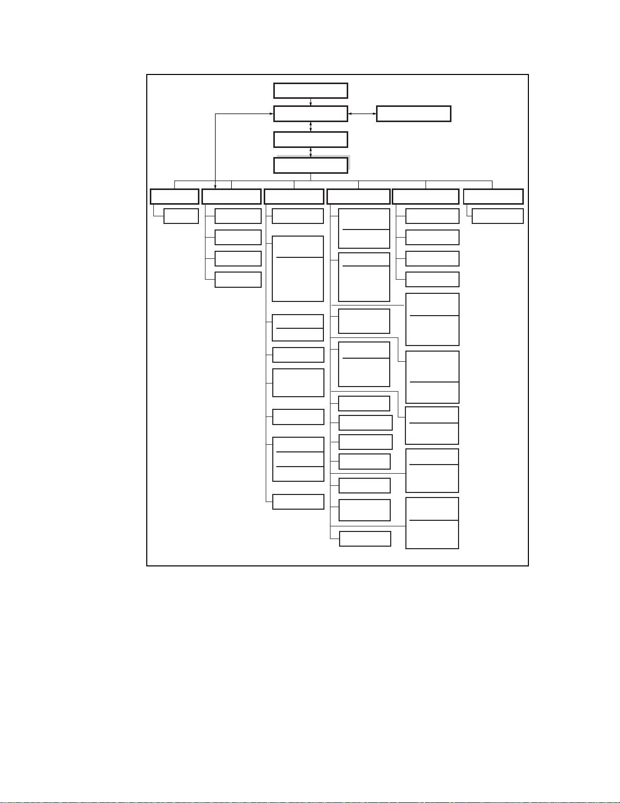
The MiniLibrary Menu Structure
Figure 2–12 shows the structure of the MiniLibrary menus.
Page 41
Power-Up Displays
Operation 2-15
From/To
Notes:
(1) Applies to Base Module
(2) Applies to Expansion Unit
* Controlled by the Security Menu
Library
DLT0
DLT1
Map Info.
Default Displays
Panel Lock*
Main Menu
Maintenance MenuShow Status MenuLoad/Unload
Clean Drive
Diagnostics
Menu
Cartridge Cycle
Friction Test
Tach Feedback
Scanner
Feedback
Demo Menu
Demo 1
Flash Update
NOVRAM
Update
Clock Update
Flash DLT
Flash from SCSI
Flash from Tape
Reboot Module
Fault Displays
Configuration Menu Show History Menu Security Menu
Set Data
Format Menu
DLT 0
DLT 1
Set SCSI Menu
Library Parity
Library Bus ID
DLT0 Bus ID
DLT1 Bus ID
Set Library
Mode (1)
Set Date Menu
Day
Month
Year
Set Baud Rate
Set Serial Number
Set Unload Mode
Set Auto Clean
Set Mail Slot (2)
Set Reserved
Slots
Set Default
Scaled AT 90% 2 times
Statistics
Error History
Initial Config.
Config History
Set Element
Base Menu
Transport Addr.
Storage Addr.
Transfer Addr.
Set
Identification
Menu
Vendor Ident.
Product Ident.
Set Time Menu
Hours
Minutes
Set Negotiation
Negotiation
Mode
Transfer Rate
Set Special
Config.
Mode PG 1F
Length
Model Number
Set Unlock Code
SHR-1196-2
Figure 2-13. MiniLibrary Menu Structure
Page 42

2-16 Compaq TL881 Minilibrary System Users Guide
Entering Menu Mode
IMPORTANT: When the Expansion Unit enters the Menu Mode, the Ready light goes
out. This means that the module is
with a SCSI ‘Not Ready’ until you exit the Menu Mode and the Ready light goes on.
To prevent accidental interruption of host operations, you can lock out the
Menu Mode using the Security Menu. See the section entitled Security Menu,
later in this chapter. When all control panels are locked, you must enter your
unlock code in order to display the Main Menu. Note that the Show Status
Menu of each module remains accessible. It may be displayed from the
module’s Default Screen at any time by pressing the
When the Default Screen appears on the screen, you can enter the Menu Mode
by pressing the
Enter button. The Main Menu shown in Figure 2–13 appears:
offline
, and responds to all commands from the host
Escape button.
SHR-1331
Figure 2-14. Main Menu
NOTE: If the control panel has been locked, the screen shown in Figure 2–14 appears
instead of Figure 2–13. You must know the unlock code for the system before you can
proceed.
SHR-1347
Figure 2-15. Panel Locked Screen
When you press the Enter button, the screen shown in Figure 2–15 appears:
Page 43

Operation 2-17
SHR-1348
Figure 2-16. Code Entry Submenu
Using the button and buttons, set the first digit of the unlock code. When
you have set it, press the
and repeat the process. When you have finished, press the
the
Enter button to confirm your entry. If the code is correct, the Main Menu
Enter button to move the cursor to the second digit
Escape button, then
is displayed. If the code is incorrect, an error screen appears.
Exiting the Menu Mode
To leave the menu mode and return to the Default Screen, press the Escape
button repeatedly. Each time you press the Escape button, the display moves
to a higher menu level. When the Main Menu is visible, pressing the
button once returns to the Default Screen. At this point, the Ready LED lights.
Escape
Navigating Through the Menu Structure
To select a submenu, move the on the display to the desired line using the
and buttons. Then press the Enter button to confirm your choice and
display the submenu. The
means that there are one or more additional items that can be reached by
scrolling, using the
■
Load/Unload
■
Show Status Menu
■
Maintenance Menu
■
Configuration Menu
■
Show History Menu
■
Security Menu
The following sections describe the submenus that correspond to each of the
Main Menu selections.
at the end of the fourth line of the Main Menu
button. The items available on the Main Menu are:
Page 44

2-18 Compaq TL881 Minilibrary System Users Guide
Load/Unload Menu
The Load/Unload Menu is described later in this chapter, under the section
entitled Loading and Unloading Tapes.
Show Status Menu
When you select Show Status, the menu shown in Figure 2–16 appears:
Figure 2-17. Show Status Menu
The items available on the Show Status Menu are:
■
Library
■
DLT0
SHR-1448
■
DLT1
■
. . .
■
DLTn
■
Map Info
Move the
up or down with the and buttons, then press the Enter
button to select the item.
Library Status Submenu
When you select Library, the menu shown in Figure 2-14 appears:
SHR-1350
Figure 2-18. Library Status Submenu
Page 45

Operation 2-19
This screen is scrollable. The list of Library Status categories available is as
follows:
■
Model Number ■ Firmware Revision
■
Date ■ Time
■
Loader Status ■ Library Configuration
■
Vendor Identification ■ Product Identification
■
Transport Address ■ Storage Address
■
Transfer Address ■ Imp/Exp Address
■
Serial Number ■ SCSI Bus ID
■
SCSI Bus Parity ■ Negotiation Mode
■
Transfer Rate ■ Unload Mode
■
Mail Slot Emulation ■ Mail Slot Count
■
Mode Page 1F Length ■ Initialize Element Status
■
Boot Version ■ Flash Type
Drive Status Menu
When you select either of the drives, the menu shown in Figure 2–18 appears:
SHR-1449
Figure 2-19. Drive Status Menu
This screen is scrollable. The list of Drive Status categories available is as
follows:
Map Information Screen
When you select Map Info, the screen shown in Figure 2–19 appears. The
location being reported appears on Line 1. The content of the bar code on the
label, up to 8 characters, appears on Line 4.
Page 46

2-20 Compaq TL881 Minilibrary System Users Guide
Figure 2-20. Map Info Submenu
The list of locations available for display on line 1 is as follows. If you do not
designate any mail slots, those lines are omitted from the list.
Depending on the report for each location, Line 2 may display either ‘Empty’,
or ‘Occupied’, or, if a magazine is absent, ‘Not Installed'.
Depending on the report for each location, Line 3 may display either ‘Label
Valid’, or ‘Label Not Present'.
For each location reported, Line 4 will display the actual bar code on the label,
up to 8 characters.
Maintenance Menu
SHR-1450
The Maintenance Menu and the options under it that are intended for operator
use are described in Chapter 5, Regular Maintenance.
Configure Menu
The Configure Menu, how to use it and the options available under it are
described in Chapter 3, Installation.
Show History Menu
The Show History Menu enables the operator to review the history of the
system. An example of the use of the Show History Menu appears later in this
chapter under the heading ‘Displaying Error Logs'. You can retrieve the
configuration history, the original configuration, as well as statistics on the
number of operations the library robotics and the drives have performed.
Security Menu
The Security Menu permits the operator to lock the control panel, preventing
inadvertent or unauthorized access to the Menu Mode, which takes the system
offline. You can display the Show Status Menu without unlocking the panel
Page 47

Operation 2-21
(and without taking the system offline) by pressing the Escape button at the
Default Screen.
When you select the Security Menu, the screen shown in Figure 2–20 appears:
SHR-1353
Figure 2-21. Security Menu
This screen is scrollable. The list of Security functions available follows:
■
Unlock All Panels ■ Unlock All Media
■
Lock All Panels ■ Lock All Media
■
Master Locking ■ Module 1 Locking
■
. . . ■ Module n Locking
■
Set Unlock Code
To change the unlock code, or to enable or disable the panel locking function,
scroll downward by pressing the
Code'. Press the
Figure 2-22. Code Select Submenu
Enter button. The screen shown in Figure 2–21 appears:
button until the is next to ‘Set Unlock
SHR-1354
An underline cursor appears underneath the first digit. To set the first digit,
press the
move the cursor to the second digit, press the
button or the button until the desired number is displayed. To
Enter button. Repeat the process
for each of the four digits. Be sure to remember the 4-digit number, as you will
need it in order to enter the Menu Mode. An unlock code of 0000 disables
panel locking.
When you have finished entering four digits, press the
Escape button, the
screen shown in Figure 2–22 appears:
Page 48
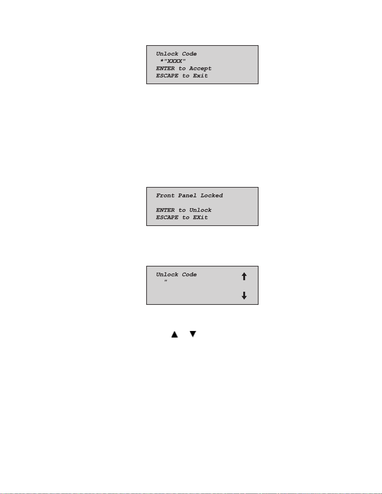
2-22 Compaq TL881 Minilibrary System Users Guide
Figure 2-23. Code Accept Submenu
Your code is shown in place of XXXX.
SHR-1355
Press the
Press the
Enter button if you want to adopt the unlock code that is displayed.
Escape button if you do not want to accept it. Press the Escape
button again to return to the Main Menu, and again to return to the Default
Screen.
The next time you attempt to enter Menu Mode, the screen shown in Figure 2–
23 appears. You can still display the Status Menu without using the security
code by pressing the
Figure 2-24. Panel Locked Screen
Escape button at the Default Screen
SHR-1347
When you press the Enter button, the screen shown in Figure 2–24 appears:
SHR-1348
Figure 2-25. Code Entry Submenu
Using the and buttons, set the first digit of the unlock code. Press the
Enter button to move the cursor to the second digit and repeat the process.
When you have finished, press the
Escape button. The screen shown in
Figure 2–25 appears:
Page 49

Operation 2-23
SHR-1356
Figure 2-26. Code Validate Submenu
Press the Enter button to validate your choice. If the code is correct, the Main
Menu is displayed. If the code is incorrect, an error screen appears. If you have
forgotten your unlock code, contact your technical support representative for
assistance.
Displaying Firmware Revision
You may display the library robotics firmware revision at any time by pressing
Escape button at the Default Screen to display the Show Status Menu. It
the
appears as one of the items on the Library Status submenu of the Show Status
Menu. Press Enter with the arrow next to Library and the revision is shown;
press Escape to bring back the Default screen.. It is also displayed on line 2
of the POST Screen and the Initialization Screens.
Displaying Error Logs
To display the error history of the module, you need to use the Show History
Menu. Access it as follows:
SHR-1357
Figure 2-27. Error History Screen
Loading and Unloading Tapes
The Load/Unload menus enable you to specify a source and a destination for a
cartridge movement. As a result, you use exactly the same procedure to load
and unload. To load or unload a tape from the front panel of the module, use
the Load/Unload menus as follows:
Page 50

2-24 Compaq TL881 Minilibrary System Users Guide
A default screen is shown in Figure 2–27. From the Default Screen, enter the
Menu Mode by pressing the
Figure 2-28. Default Screen
The Main Menu shown in Figure 2–28 appears.
Figure 2-29. Main Menu
Enter button.
SHR-1446
SHR-1331
The is next to the line that reads ‘Load/Unload'. Press the Enter button to
display the first Load/Unload submenu, which is shown in Figure 2–29:
SHR-1451
Figure 2-30. Load/Unload Initial Screen
In Figure 2–29, the is next to line 2 of the display. Line 2 shows the top
item in a scrollable list of sources. Note that a
the bottom line. This indicates that the
has appeared on the right of
button may now be used to scroll
through the list, and that the top item on the list is displayed. As soon as you
press the
button, three things happen:
The list scrolls down one item (only line 2 scrolls).
appears on the right of line 1 of the display. This indicates that there is
A
one or more items above the item displayed on line 2.
Page 51

Operation 2-25
The * at the left of line 2 disappears. This is because the * indicates the current
selection or the default selection, and you have scrolled the default selection
offscreen, and haven’t yet selected an item from the list.
NOTE: The contents of the lists on line 2 and line 4 will vary as follows:
Initial Screen - ‘From’ Line
The list on line 2 in Figure 2–29 (the ‘From’ line) will include every drive and
every magazine slot (including mail slots) that has a cartridge in it (you can’t
get a cartridge from a slot or drive that is empty).
Initial Screen - ‘To’ Line
The list on line 4 of Figure 2–29 (the ‘To’ line) will include all of the valid
destination choices, that is, drives and slots that are empty (you can’t put a
cartridge into a slot or drive which already has one in it).
Scroll List - ‘To’ Line
There is another limitation on the ‘To’ list. If you have selected a drive on the
‘From’ screen, the ‘To’ list can include only slots. If you have selected a slot
on the ‘From’ screen, the ‘To’ list can contain only drives.
Let us assume that you want to load the cartridge that is in Slot 4 into any
available drive. Use the
button to scroll line two to Slot 4. The screen
shown n Figure 2–30 appears:
From:
SLot4
To:
*DLT0
SHR-1452
Figure 2-31. Load/Unload ‘From‘ Entry Screen
When you have scrolled to your desired source, press the Enter button to select it.
Notice that in Figure 2–30, two changes occur in the display.
The * reappears at the beginning of line 2, indicating that you have made a
selection.
now moves to line 4, indicating that you may now select a destination.
The
Page 52
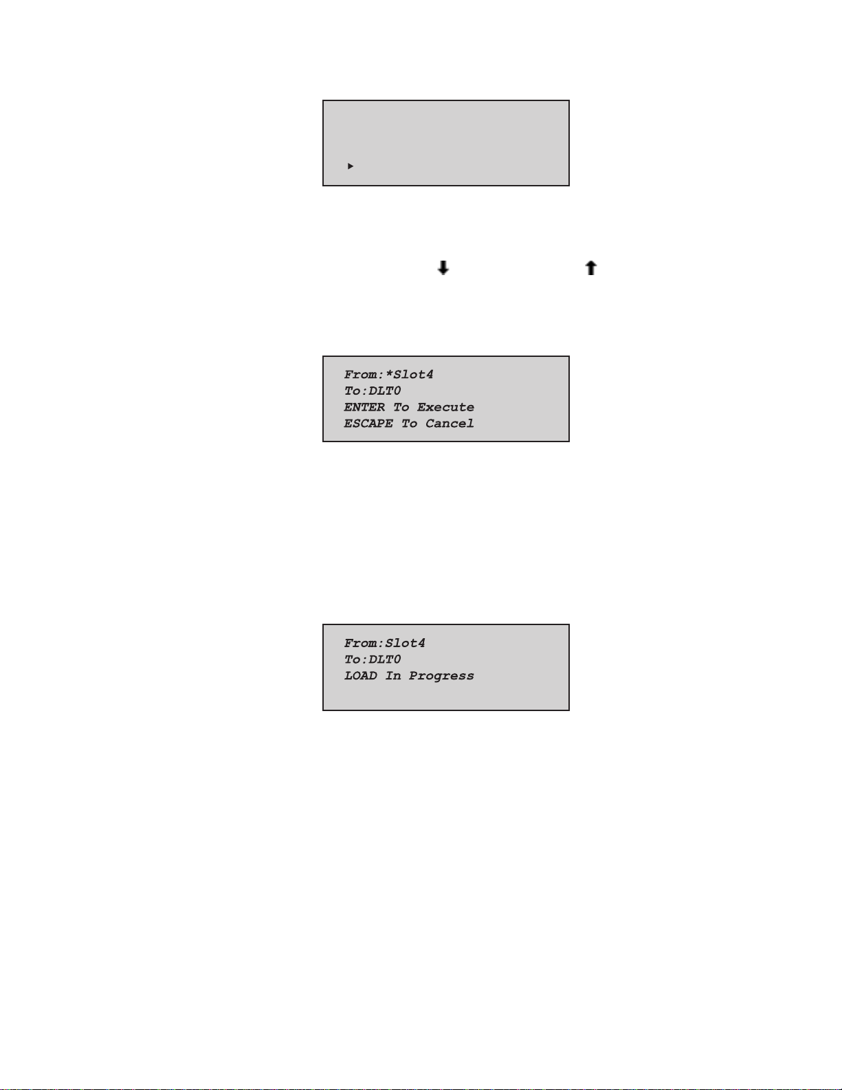
2-26 Compaq TL881 Minilibrary System Users Guide
From:
*Slot4
To:
*DLT0
Figure 2-32. Load/Unload ‘To’ Entry Screen
You can now simply press the Enter button to select DLT0 as the destination.
Note that there is no
are no additional choices because 1) you have selected a slot as the source, so
the destination must be a drive, and 2) DLT1 already has a cartridge in it, so it
cannot be a valid destination. Press the
response, the Confirmation Screen shown in Figure 2–32 appears:
SHR-1453
at the end of line 4, nor at the end of line 1. There
Enter button to select DLT0. In
SHR-1454
Figure 2-33. Confirmation Screen
As the confirmation screen indicates, to execute the load or unload, press the
Enter button. If the confirmation screen does not show your intended source
and destination, press the
When you press the
Escape button to return to the ‘From’ entry screen.
Enter button, the screen shown in Figure 2–33 appears. If
the source is a drive, the word ‘Unload’ appears in place of the word ‘Load’ on
line 4.
SHR-1455
Figure 2-34. Load/Unload ‘In Progress’ Screen
When the load or unload operation is finished, the Default Screen reappears.
Page 53

Inserting and Removing Cartridges
When inserting cartridges, be sure that the slot you intend to use is not already
reserved in the system map for a cartridge in a drive. The best way to avoid
conflicts is to unload all drives, either through your host computer software or
by using the Load/Unload command on the Main Menu, described in the
previous section.
The tape magazine must be removed from the module in order to insert or
remove cartridges. To insert or remove the magazine, the following conditions
must be met.
The Magazine Security Lock (Figure 2–34) must be unlocked, using the key
supplied with the module. When the Magazine Security Lock is locked, the
Unlock/Open button has no effect. If the module is installed in a reasonably
secure environment, you may elect to leave the Magazine Security Lock in the
unlocked position.
Media locking on the Security Menu must be disabled. See Figure 2–20.
The host computer must allow medium removal. The host computer can
enable or disable the
Medium Removal command. When you press the
message ‘Magazine Locked” will be displayed.
Unlock/Open button using the SCSI Prevent Allow
Operation 2-27
Unlock/Open button, the
The Expansion Unit must be ready, and not actually executing a command.
IMPORTANT: When you enter the Menu Mode, the Ready light goes out. The magazine
cannot be inserted or removed unless the Ready light is on. To remove the magazine
when a failure prevents the Ready light from illuminating, refer to the section entitled
Emergency Magazine Removal
.
Page 54

2-28 Compaq TL881 Minilibrary System Users Guide
Figure 2-35. Magazine In Place
Figure 2-36.
Magazine security lock
1
Unlock/Open button
2
1
2
SHR-1230
Removing a Magazine
Figure 2-37. Main Menu
Figure 2-38. Main Menu, Scrolled
SHR-1331
SHR-1363
Page 55
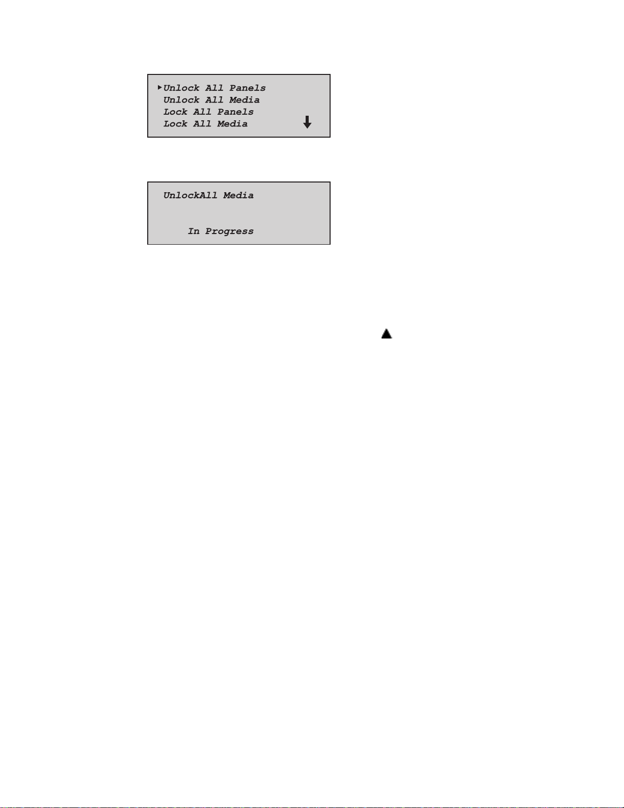
Operation 2-29
SHR-1353
Figure 2-39. Security Menu
SHR-1364
Figure 2-40. Unlock All Media Screen
Emergency Magazine Removal
If a fault occurs that prevents removal of the magazine, turn the power off for
thirty seconds. Power up while continuously pressing the
to hold the button until all of the indicators on the control panel light, then go
out. Release the button. The magazine may now be removed.
button. Continue
If you are unsuccessful in removing the magazine using this procedure,
contract your technical support representative for further advice.
Inserting Cartridges Into the Magazine
A full magazine is shown in Figure 2–39. Insert cartridges so that the label end
with the write protect switch is outward, with the write protect switch toward
the bottom of the magazine. The lowest numbered cartridge slot in the
magazine is closest to the handle.
Page 56

2-30 Compaq TL881 Minilibrary System Users Guide
1
3
Figure 2-41. 10-Slot Tape Magazine with Cartridges Installed
Label
1
Slot 0
2
Write protect switch
3
Inserting a Magazine
Figure 2-42. Main Menu
2
SHR-1231
SHR-1331
Figure 2-43. Main Menu, Scrolled
SHR-1363
Page 57

Figure 2-44. Security Menu
Figure 2-45. Unlock All Media Screen
Operation 2-31
SHR-1353
SHR-1364
Figure 2-46. Lock All Media Screen
MiniLibrary Base Module
The front panel of the MiniLibrary Base Module is nearly identical to that of
the Expansion Unit. The panel includes a power switch for the module, the
magazine door, the Magazine Security Lock, the Unlock/Open button with its
Locked indicator. The control panel, shown in Figure 2–4, has one more LED
indicator than that of the Expansion Unit. Figure 2–45 shows the MiniLibrary
Base Module front panel.
SHR-1365
Page 58
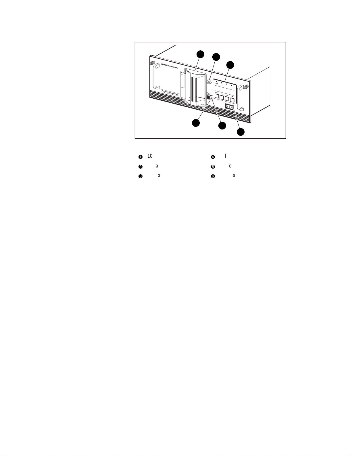
2-32 Compaq TL881 Minilibrary System Users Guide
1
2
3
U
s
e
C
l
e
Drive
a
n
e
r
L
Fault
o
a
d
e
r
F
a
u
lt
4
Figure 2-47. MiniLibrary Base Module Front Panel
10-Cartridge magazine
1
Magazine security lock
2
Control panel
3
5
Unlock/Open button
4
Locked indicator
5
Power switch
6
6
SHR-1195
The Magazine Security Lock, the Unlock/Open
Button and the Locked Indicator LED
These features are described in Inserting and Removing Cartridges.
Tape Requirements
The MiniLibrary system uses ECMA-approved and ANSI proposed-standards
DLTtape cartridges. The DLTtape cartridge is a four-inch square plastic
cartridge. According to the media manufacturer, the cartridge and the medium
are designed to withstand 1,000,000 passes, and to have a shelf life of 30 years
when properly stored.
Cartridge Handling and Storage
A DLTtape cartridge should be stored vertically until you select it for use. Do
not expose a cartridge to moisture or direct sunlight. Maintain a clean, dustfree working and storage environment.
If a DLTtape cartridge is dropped:
■
Inspect the cartridge carefully before you insert it into a MiniLibrary
magazine or any drive.
Page 59

Operation 2-33
■
Shake the cartridge while listening for the sound of a broken part. Any
rattling sound makes a cartridge unfit for use.
■
Inspect the case for distortion or cracks.
■
Inspect the leader by opening the cartridge door as shown in Figure 2–
46. The leader should be positioned as shown in view (1), and should
protrude at about a five-degree angle from the case. If the leader is out
of position, do not use the cartridge; damage to the drive could result.
Under certain conditions, DLT Tape may stick to the drive read/write head
during operation. Damage to media, failure of commands or batch jobs to
execute, with resulting errors or hangs; failure to unload; apparent need to
swap out the drive.
When tapes are stored in an environment different from that of the drive,
ensure that they are acclimatized, by moving them to a location in close
proximity to the drive before attempting to use them. Ideally, tapes should be
allowed to acclimate for a time equal to the duration of their storage away
from the drive, or 24 hours, whichever is less.
Reports have verified that sticking will occur almost immediately with older,
used tapes which have been stored at 20°C and 75% humidity, when those
tapes are used in a TZ87 drive kept at a higher temperature and lower
humidity. High tape humidity causes sticking from HYDROLYSIS, a
degradation of the tape which can be reversed by storing the tape for a while in
a dry environment Test conditions (cool, damp tapes and warm, dry drives)
have produced “stiction” at will, but other conditions may also cause it.
Remember to acclimatize tapes before use. Long-term storage specifications
are more stringent than those for shorter periods. Cartridges intended for longterm archiving shall be stored in room conditions of 23°C +/-5 (73°F +/-9 at
50% +/-10% relative humidity.
Page 60

2-34 Compaq TL881 Minilibrary System Users Guide
1
2
Figure 2-48. DLT Tape Cartridge
Leader
1
Write protect OFF
2
Write protect ON
3
3
SHR-1232
Write Protection
The write protection switch of a DLT tape cartridge is also shown in Figure
2–46. To enable data recording, slide the write protect switch to the right so
that no orange color is visible through the window in the write protect switch
(2). To write protect the DLT tape cartridge, slide the write protect switch to
the left until the orange indicator shows through the window on the write
protect switch (3).
Barcode Labels
Barcode labels are included with the TL881 MiniLibrary and Expansion Unit.
Additional labels can be ordered (refer to Appendix B). The label slips into the
slot adjacent to the write-protect switch on each tape cartridge. The code used
may be Code 39, Codebar, 2-of-9, standard 2-of-5, or interleaved 2-of-5, with
a length of 8 digits. Minimum element width is 7.5 mm.
TL881 Components
There are four basic components in the TL881 MiniLibrary system:
Page 61

Operation 2-35
■
The TL881MiniLibrary Base Module
■
The MiniLibrary Expansion Unit (Master)
■
The MiniLibrary Data Unit
■
The Pass-Thru Mechanism
Every Pass-Thru Mechanism has one Expansion Unit and any combination of
up to eight of the remaining components stacked in a rack. The Expansion
Unit can move media freely within itself and between the MiniLibrary Base
Modules and the Data Units with the Pass-Thru Mechanism™.
In the MiniLibrary system, you can combine modules to provide the right
combination of capacity and performance for your requirements. The
architecture allows you to change or add to the mix of modules to optimize
throughput, capacity, or both as your storage requirements change.
When connected as a system, the robotics in MiniLibrary Base Modules and
Data Units operate from Expansion Unit commands. The host computer(s) are
not dependent on the internal geometry of the system, or on the actions or
capabilities of any of the slave modules. The Expansion Unit presents, to the
host(s), a single SCSI medium changer device with a single SCSI Medium
Transport element, several SCSI storage elements equal to the number of
cartridge magazine slots, several SCSI Import/Export elements as specified by
the user during configuration of the Expansion Unit, and a number of SCSI
Data Transfer elements equal to the total number of drives in the system.
Storage Architecture
The MiniLibrary architecture is uniquely suited and designed for expanding
storage needs. The MiniLibrary architecture enables the robotics in each of the
MiniLibrary components to exchange cartridges with the Pass-Thru
Mechanism, and integrates the robotics in the individual components and the
Pass-Thru Mechanism into a single, high-performance library robotics system.
The MiniLibrary is easily modified – by adding modules and extending the
Pass-Thru Mechanism – to adapt to expanding storage needs. You can add
drives for faster performance or magazine space for greater capacity, as
needed. At power-up the MiniLibrary updates the system map, signaling the
host of the need for expansion.
The Expansion Unit
The Master Expansion Unit integrates the robotics in the individual modules
into a single coordinated library robotics system. The Expansion Unit
Page 62

2-36 Compaq TL881 Minilibrary System Users Guide
performs and maintains an inventory of all media residing in the system,
including bar code data, if the modules are equipped with bar code readers. All
necessary system control operations can be performed from the control panel
of the Expansion Unit, as well as from the host through software. The SCSI
interface for the library robotics is designed for high-speed communication
with the host, and is available in standard SCSI-2, Fast SCSI-2 or Fast/Wide
SCSI configurations.
In addition to system control functions, the Expansion Unit has a 16-cartridge
magazine with a random access robotic mechanism. The module robotics
moves cartridges between the Pass-Thru Mechanism and any of the 16
cartridge storage locations.
You can designate a magazine in one of the slave modules as a mail slot for
inserting or removing one or more single cartridges, which implements the
SCSI Import/Export commands.
NOTE: a magazine reserved for Import/Export service may not be used for data
storage.
The MiniLibrary Base Module
The MiniLibrary Base Module has either one or two DLT drives and a 10cartridge magazine with a random access robotic mechanism.
The Data Unit
The LXC0016 Data Unit has a 16-cartridge magazine, a random access robotic
mechanism , and no tape drives. The module robotics, under control of the
Expansion Unit, moves cartridges between the Pass-Thru Mechanism and any
of the 16 cartridge storage locations.
SCSI Interface Configurations
The MiniLibrary system standard SCSI interfaces are SCSI-2 for systems
equipped with 2000XT drives and Fast SCSI-2 for systems equipped with
4000 drives. Both of these use high-density 50-pin D-series connectors. Also
available, in systems equipped with 7000 series drives, is a Fast/Wide SCSI
interface using high-density 68-pin D-series connectors.
Page 63

SCSI Bus Performance Considerations
The data transfer rate of the DLT MiniLibrary is dependent on the type of
drives and on the SCSI bus configuration. The bandwidth of the SCSI bus is
limited.
Drives
With a standard SCSI interface, modules equipped with the DLT20/40 series
can provide a maximum sustained native transfer rate of 1.5 MB/second. With
both drives operating, the DLT20/40 native transfer rate is 3.0 MB/second.
The rates for compressed data are the native rates multiplied by the
compression factor, which depends on file content, but averages
approximately 1.7.
Internal Cabling Configuration
The differential MiniLibrary system is wired in an independent-bus SCSI
configuration: the robotics and each of the drives has its own SCSI bus. SCSI
jumpers are available for those applications requiring that some combination
of drives and robotics are daisy-chained to a single SCSI bus.
Operation 2-37
The single-ended table-top unit has the robotics and first DLT drive daisychained internally to shorten the total internal cable length. The second drive is
on an independent bus.
Bus Length Limitations
The single-ended SCSI-2 bus is limited to 6 meters in length, and the singleended Fast SCSI-2 bus is limited to 3 meters overall length. In contrast,
differential SCSI-2 and Fast SCSI-2 buses may be up to 25 meters long.
Physical Configuration
All modules in a MiniLibrary system must be mounted in a rack except for the
table top module version. When a system is ordered, all the modules are
supplied in a rack-mount configuration. Modules cannot be operated alone
except for the MiniLibrary Base Module, which can be converted to operate as
a free-standing 10-slot library.
Page 64
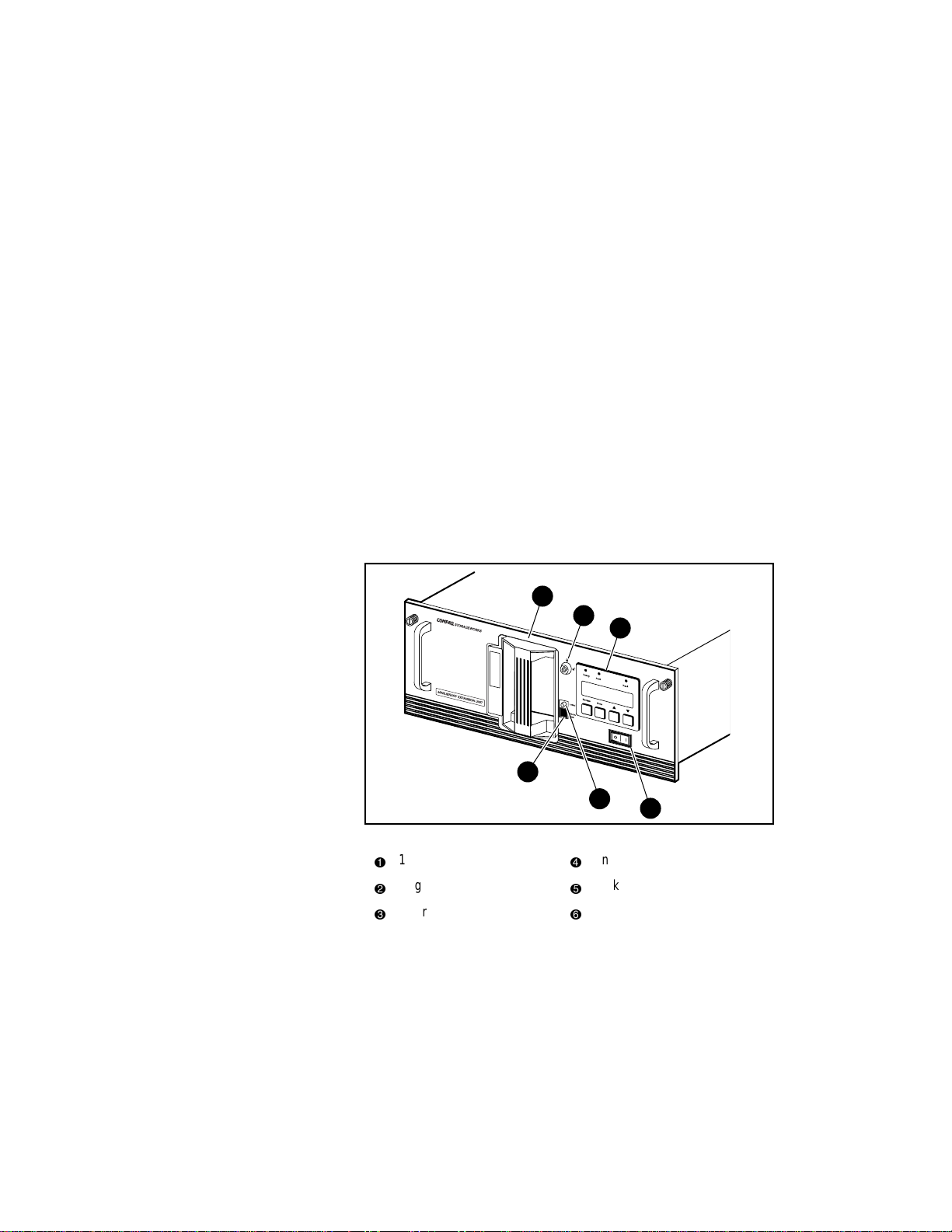
2-38 Compaq TL881 Minilibrary System Users Guide
System Expansion
A DLT MiniLibrary system can be expanded in capacity or performance or
both by adding or removing components. Associated with each component is a
section of the Pass-Thru Mechanism. The MiniLibrary Storage system
firmware integrates the robotics in the individual modules and the Expansion
Unit Pass-Thru Mechanism into a single high-performance library robotics
system.
Free-Standing MiniLibrary Base Modules
Conversion
You can add existing MiniLibrary Base Modules to your system by changing
firmware, resetting internal jumpers, removing the pass-through cover plate,
and in some cases converting from desktop to rack mount. These tasks should
be performed by qualified service personnel. Contact your technical support
representative for instructions.
Features
Figures 2–47 through 2–52 show some of the external features of the
Expansion Unit, the MiniLibrary Base Module, and the Data Unit.
1
2
3
4
5
Figure 2-49. Expansion Unit and Data Unit Front View
16-Cartridge magazine
1
Magazine security lock
2
Control panel
3
Unlock/Open button
4
Locked indicator
5
Power switch
6
6
SHR-1194
Page 65

Operation 2-39
1
2
3
Us
e
C
lean
D
riv
er
e
Loa
F
a
der
u
lt
Fault
Figure 2-50. MiniLibrary Base Module Front View
Control Panel
The control panels for all modules are the same, except for the number of LED
indicators. The control panel features a 4-line by 20-character backlit LCD
display, three or four LED indicators, and four buttons. The buttons enable the
operator to navigate through the menu structure to select and display operating
modes, device status, diagnostic and maintenance functions, device history and
error statistics, and system configuration.
Display
The backlit 4-line by 20-character control panel display provides a highly
intelligible presentation of drive and loader status, menu choices and error
messages. The scrolling feature greatly expands the amount of information
available to the operator. In the MiniLibrary Expansion Unit, status
information is available for the entire system. The slave modules display other
information as needed for localizing malfunctions.
10-Cartridge magazine
1
Magazine security lock;
2
Unlock/Open button
3
4
5
Locked indicator
4
Control panel
5
Power switch
6
6
SHR-1195
Magazine Security Lock
The Magazine Security Lock is a key-operated switch on the front panel of
each module. It can be used to prevent inadvertent removal of the cartridge
magazine.
Page 66

2-40 Compaq TL881 Minilibrary System Users Guide
Power Supply
The AC Power switch is located on the front panel of the module. The
autoranging power supply will adjust automatically to either of two operating
voltage ranges. The ranges are 100-120 VAC and 200-240 VAC. The power
supply is capable of operating at 50 or 60 Hz without any adjustment or
modification. AC power is supplied to the power supply by a single IECcompatible socket which can be connected to any properly grounded outlet.
Tape Cartridge Magazines
The ten-cartridge and sixteen-cartridge magazines are removable from the
front panel, but may be protected from tampering by any of three means: 1) a
key-operated Magazine Security Lock which must be unlocked before the
magazine can be removed, 2) an electronic combination lock operated by
using buttons on the Expansion Unit control panel, and 3) issuance by the host
of a SCSI ‘Prevent Medium Removal’ command. The rugged carbon-fiberreinforced polymer magazine fits into an extruded track, which assures precise
positioning with respect to the library robotics. A ten-cartridge tape magazine
is shown in Figure 2–49.
Page 67

4
3
2
Figure 2-51. MiniLibrary Base Module 10-Cartridge Magazine
Slot 0
1
Front label slide slot
2
Barcode label slide slot (not used)
3
Slot 9
4
Operation 2-41
1
SHR-1226
1
5
4
3
Figure 2-52. Expansion Unit Rear View
Pass-Thru mechanism
1
3
motor drive
Power connector
2
4
5
2
Slave module robotics interface
connectors
Library robotics SCSI interface
Flash connector
SHR-1227
Page 68

2-42 Compaq TL881 Minilibrary System Users Guide
1
4
3
2
SHR-1228
Figure 2-53. MiniLibrary Base Module Rear View
SCSI interface
1
Expansion unit interface
2
Power connector
3
Fan
4
The differential unit shown in Figure 2–51 has 6 ports. A single-ended version
has four ports.
2
1
SHR-1321
Figure 2-54. Data Unit Rear View
Power connector
1
Expansion unit interface
2
Page 69

Integral Fan Cooling
A single forced-air fan is mounted inside each module to provide optimum
cooling for critical parts, and to prevent the drive and robotics electronics,
motors and power supply from overheating.
Library Robotics
The DLT MiniLibrary system features library robotics that can load any of the
cartridges stored in any magazine in the system into any of the DLT tape
drives, moving cartridges among as many as nine modules within the DLT
MiniLibrary system. The robotics design utilizes the Compaq Library
Robotics, which is known for ruggedness and reliability.
Bar Code Reader
The optional bar code reader may be mounted on the cartridge shuttle in each
module. It reads bar code labels attached to each cartridge, and maintains the
bar code data in memory as part of the library System Map. Upgrade kits to
add the bar code reader are available for the MiniLibrary Expansion Unit, the
MiniLibrary Base Module and the Data Unit.
Operation 2-43
Page 70

Installation Overview
This chapter describes the complete MiniLibrary System installation process
from planning and parts identification to mechanical installation, cabling, and
configuration.
Introduction
There are three basic areas for installing a MiniLibrary System: Mechanical
installation; cabling; and configuration.
Chapter
3
Installation
Mechanical installation consists of:
■
Assembling the Pass-Thru mechanism - the two-module version is
factory assembled.
■
Installing the Expansion Unit, the MiniLibrary Base Module(s) and the
Data Units. Instructions are provided for all rack types: Compaq
Cabinet, EIA/RETMA Standard 19” cabinet, and StorageWorks SW500,
SW600, or SW800 Metric cabinet
■
Installing the Pass-Thru mechanism in the rack
Cabling consists of:
■
Interconnecting the Data Units and MiniLibrary Base Modules with the
Expansion Unit
Page 71

3-2 Compaq TL881 Minilibrary System Users Guide
■
Connecting the Expansion Unit to the Pass-Thru mechanism motor
■
Connecting the MiniLibrary Base Module drive SCSI buses to host
SCSI interfaces
■
Connecting the Expansion Unit to a host SCSI interface
■
Terminating the buses properly
Configuration consists of:
■
Using the Configure Menu to customize the configuration options to
your particular application
The remainder of this chapter describes each of these steps.
Planning Your Installation
The MiniLibrary System is designed for mounting in a Compaq Cabinet,
StorageWorks SW500, SW600, SW800 or a standard 19-inch EIA/RETMA
equipment rack with a depth of 24 to 30 inches. Each module is shipped with
EIA/RETMA slides installed. Additional hardware for mounting in Compaq
and SW500, SW600, and SW800 cabinets is included
Every Compaq MiniLibrary System includes:
■
One Expansion Unit
■
One Expandable Pass-Thru Mechanism
■
One to five MiniLibrary Base Modules or Data Units, each with one or
two DLT20/40 drives
The Expansion Unit has 16 slots and no drives, and serves as controller of the
MiniLibrary System. The MiniLibrary Base Modules each have 10 slots plus
one or two drives. The Expansion Unit, the Data Unit and the MiniLibrary
Base Module(s) each occupy 7 inches of rack space height.
The Pass-Thru mechanism is composed of a motor drive assembly plus
sections of track whose combined length is equal to the combined heights of
the Expansion Unit plus the MiniLibrary Base Modules. One extension section
of track is needed for the installation of each additional MiniLibrary module.
Positioning the Modules
The Expansion Unit must be mounted at the top of the stack, which places its
control panel at a convenient height. The control panels of the Data Unit
MiniLibrary Base Modules are of secondary importance, as they serve mainly
Page 72

to help localize system failures. When installed, the motor drive assembly of
the Pass-Thru mechanism is directly behind the Expansion Unit.
Data Units and MiniLibrary Base Modules may be installed anywhere below
the Expansion Unit, in any order. There may be a slight performance
advantage in making the MiniLibrary Base Modules contiguous, but gaps are
permitted. The size of a gap is limited by the fact that each gap must be
bridged by some number of 7” Pass-Thru mechanism track sections. For
safety, available cover plates should be installed on all Pass-Thru mechanism
sections which are not connected to MiniLibrary System modules.
The Expansion Unit senses the position of each module during initialization at
power-up. Even if there are gaps between modules, the system will operate
correctly. If you plan to leave gaps between modules, be sure to order
additional Pass-Thru mechanism track segments and cover plates equal to the
length of the gap.
Mechanical Installation
Assembly of the Pass-Thru mechanism requires experience working with
moderately complex mechanisms, and the ability to follow directions
carefully.
Installation 3-3
Identifying the Parts of the Pass-Thru
Mechanism
Locate and identify the Pass-Thru mechanism internal and external parts. The
Pass-Thru mechanism is made up of the following external parts, shown in
Figure 3-1:
Page 73

3-4 Compaq TL881 Minilibrary System Users Guide
5
8
7
6
8
5
6
8
4
5
4
Figure 3-1. Pass-Thru Mechanism External Parts
Motor drive section
1
Extension sections
2
Support brace
5
Left and right rack slide
6
extensions
Pass-Thru base with idler
3
Angle brackets
7
pulley
4
Tie bars
L-shaped nut plates
8
1
2
4
3
6
8
SHR-1233
NOTE: The slide extensions, 6 in Figure 3-1, are not enclosed with the Pass-Thru
mechanism parts. They are supplied as part of the installation hardware for the slides that
come with each of the modules.
Follow the instructions in the section entitled Mechanical Installation of the
Expansion and MiniLibrary Base Modules. After the rack slides and the
MiniLibrary Base Modules are in place, and after the Pass-Thru mechanism is
assembled, you will install the Pass-Thru mechanism in the rack by attaching
the support braces
L-shaped nut plates
5
to the slide extensions 6 using the angle brackets 7 and
8
.
The internal parts you will need to recognize during assembly are shown in
Figure 3-2 Figure 3-3.
Page 74
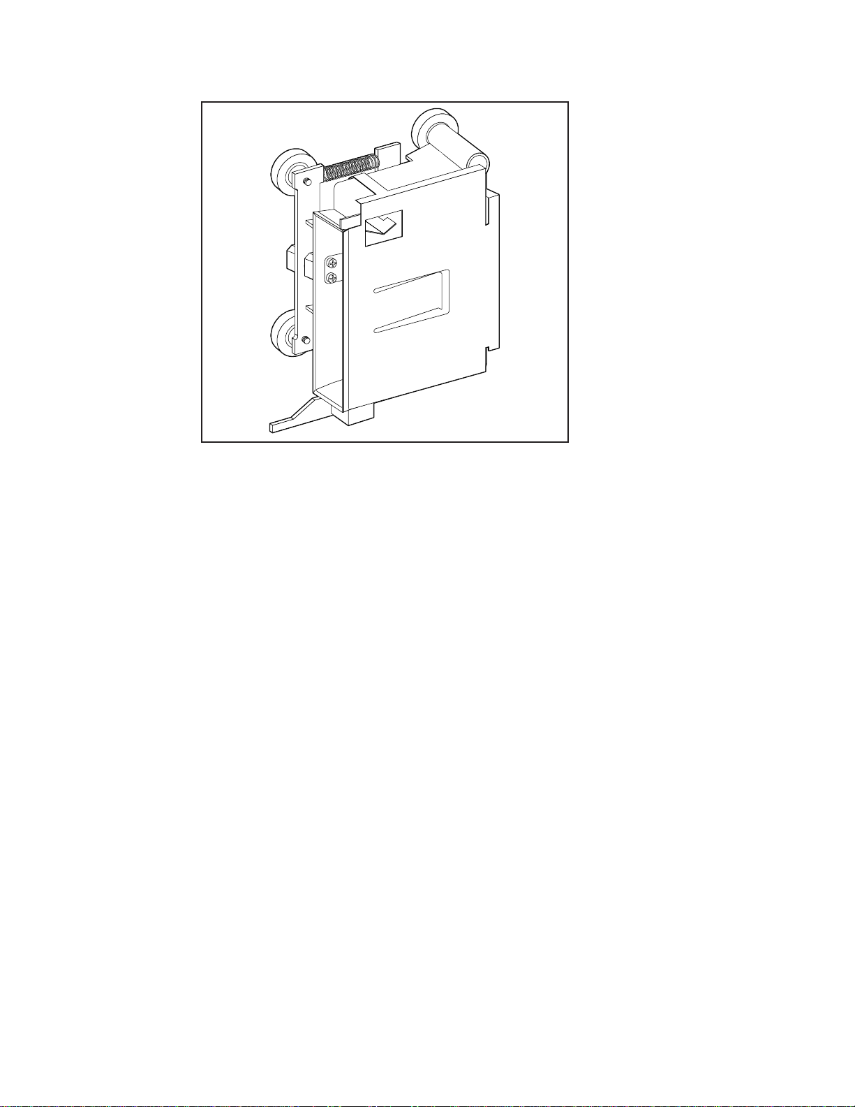
Figure 3-2. Pass-Thru Mechanism Car (Front View)
Installation 3-5
SHR-1234
Page 75
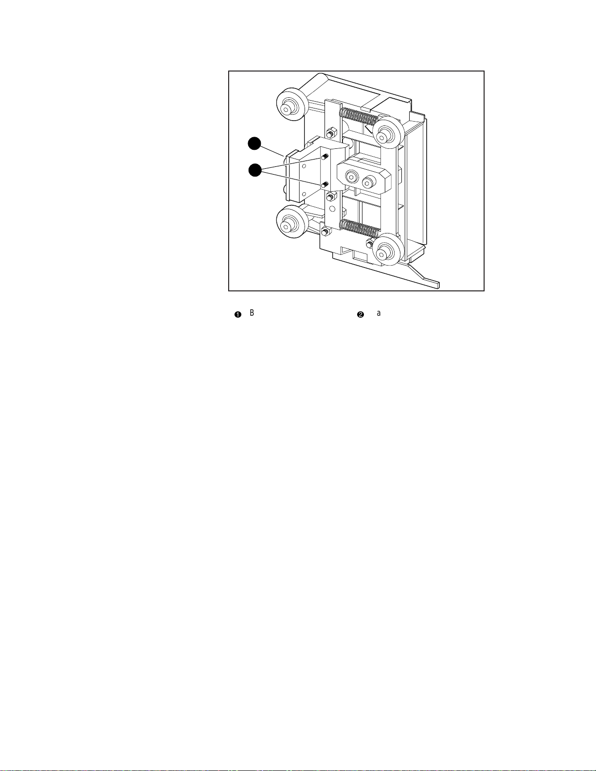
3-6 Compaq TL881 Minilibrary System Users Guide
1
2
Figure 3-3. Car Rear View Showing Belt Block
Belt block
1
Captive screws
2
SHR-1235
The belt block comes fastened to the back of the car with two captive screws.
Carefully note the orientation of the block with respect to the car, as shown in
Figure 3-3.
Orientation of Parts During Assembly
To determine the orientation of an extension section, examine the flanges on
the edges of the section, and note that they are dissimilar. Position the section
so that its orientation matches that of the elevator base.
Figure 3-4 shows a typical Pass-Thru mechanism assembly. The motor drive
section always goes on top, and the base section with the idler pulley always
goes on the bottom. Extension sections are mounted between the motor drive
section and the base section. All sections are joined together with tie bars. For
systems up to four modules, two support braces are needed, one attached to the
motor drive and one to the base section. For larger systems, a third support
brace should be mounted near the center of the Pass-Thru mechanism.
Preparing to Assemble the
Pass-Thru Mechanism
You will need a clean, flat work area such as a table or work bench. The
surface should be long enough to support the full height of the Pass-Thru
Page 76

Installation 3-7
mechanism. The height is equal to the height of the stack of modules in your
system plus any gaps you intend to include in the stack. Use the following
procedure to assemble your Pass-Thru mechanism.
Assembling the Pass-Thru Mechanism
In most cases, you have received a pre-assembled Pass-Thru mechanism. If its
length is correct for your system, turn to the section entitled Mechanical
Installation of the Expansion and MiniLibrary Base Modules and continue on
to the end of the chapter. If you need to add sections, please take a few
minutes to read this section and the section entitled Installing the Belt, before
proceeding to Adding to an Existing Pass-Thru Mechanism.
NOTE: References to left and right refer to the position of the part when the Pass-Thru
mechanism is assembled and mounted in the rack, as viewed from the front of the rack.
Refer to Figures 3-1 and 3-4.
1. Place the base section, with the inside facing down, overhanging the
right end of the work area, with the bottom plate of the section toward
the right.
2. Place each of the extension sections, with the inside facing down, in a
row aligned edge-to-edge beginning with the base section. The bottoms
of the sections should be toward the right. Omit the motor drive at this
time.
3. Center one of the support braces across the rear of the base section over
the holes on the rear surface of that section.
4. Insert two M4 x 20 Phillips sems screws through the holes in the support
brace into the holes in the base section, and tighten.
Page 77
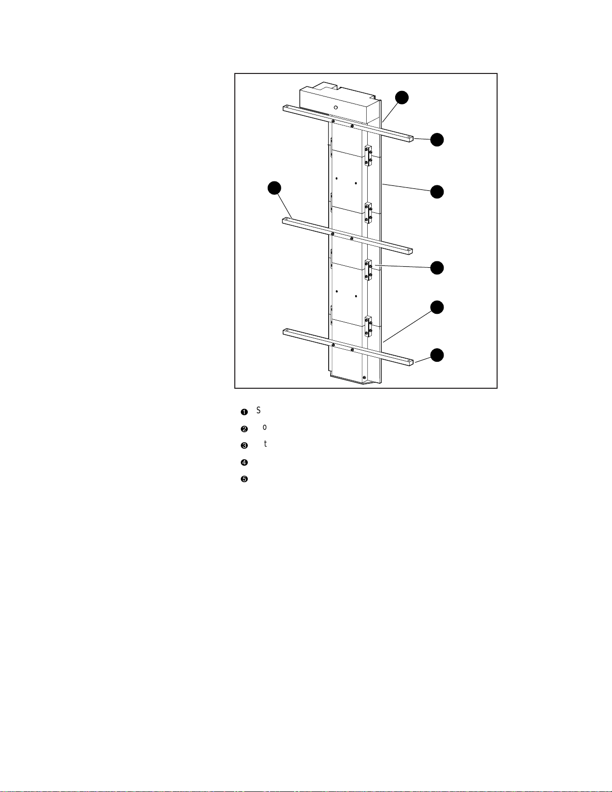
3-8 Compaq TL881 Minilibrary System Users Guide
2
1
1
Figure 3-4. Pass-Thru Mechanism Assembled
Support brace
1
Motor drive section
2
Extension section
3
Tie bar
4
Base section
5
3
4
5
1
SHR-1236
Place pairs of tie bars so that they straddle all of the joints where sections
come together. Be sure that the beveled edge is toward the inside corner of the
sections.
5. Install two M3 x 20 mm Phillips sems screws through each tie bar into
the threaded holes in the flanges of the extrusion sections. Tighten
finger tight only. Insert two M3 x 20 mm sems screws through each tie
bar into the side of the extrusion sections and finger tighten.
Page 78

6. Firmly press the neighboring sections together while tightening the two
M3 x 20 mm screws through each tie bar into the flanges of the sections.
Alternately tighten the screws into the flanges and those into the sides of
the extrusions to ensure that each tie bar is drawn into the corner of the
extrusion.
IMPORTANT: Be careful not to overtighten these screws.
7. Inspect the joint to see that the sections are well aligned, with minimal
irregularities and gaps.
8. Repeat steps 6, 7, and 8 for each pair of sections. It may be necessary to
use suitable blocks to support the row of sections so that neither the
motor housing nor the bottom flange of the base section touches the
work surface while you are connecting the motor drive section.
9. Center one of the support bars across the rear of the motor drive section
over the holes on the rear surface of that section.
10. Insert two M4 x 20 Phillips sems screws through the holes in the support
brace into the holes in the motor drive section, and tighten.
11. Go to the next section, Installing the Belt.
Installing the Belt
Installation 3-9
Refer to Figures 3-5 through 3-9.
1. Turn the assembled Pass-Thru mechanism over so that the motor points
upward.
2. Referring to Figure 3-6, locate the tensioner ramp in the base section.
Compress the spring until the hole in the tensioner ramp is aligned with
a hole in the base section. Insert an 0.050” Allen wrench or a paper clip
through the holes. This sets the idler pulley for zero belt tension.
Page 79
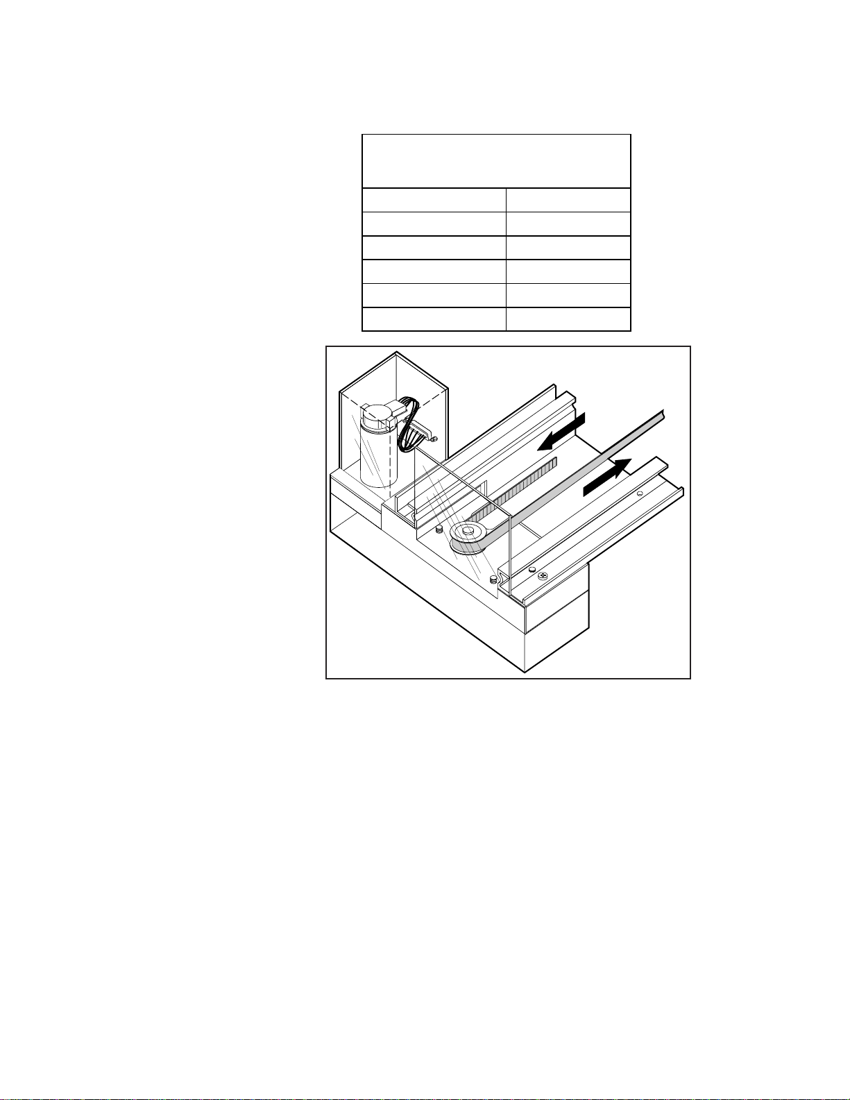
3-10 Compaq TL881 Minilibrary System Users Guide
3. Locate the length of toothed belt that was enclosed with the extension
section.
Belt Length for Various System Sizes
Number of Modules Length of Belt
2 27 inches
3 41 inches
4 55 inches
5 69 inches
6 83 inches
Table 3-1
SHR-1237
Figure 3-5. Threading the Belt through the Drive Section
4. Refer to Table 3-1 for the required belt length for your system. After
double-checking the length specified, cut the belt between teeth.
5. With the toothed side of the belt toward you, position the right end of
the belt about halfway along the Pass-Thru mechanism.
6. Referring to Figure 3-5, thread the left end of the belt counter-clockwise
around the motor drive pulley.
Page 80

Installation 3-11
7. Referring to Figure 3-6, thread the belt from the motor drive counter-
clockwise around the idler pulley and back to the right end.
8. Holding the ends of the belt as shown in Figure 3-7, the two ends should
be touching or very slightly overlapping.
Figure 3-6. Threading the Belt through the Base Section
SHR-1238
Page 81
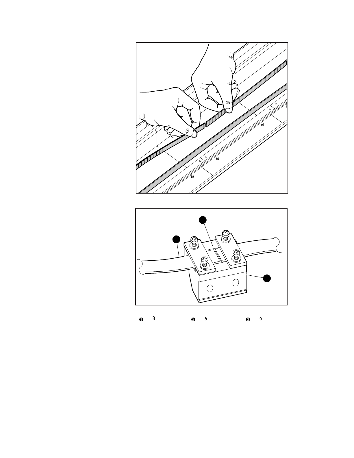
3-12 Compaq TL881 Minilibrary System Users Guide
SHR-1239
Figure 3-7. Checking Belt Length
2
1
Figure 3-8. Belt Block With Belt In Place
Belt
1
2
Gap visible
3
SHR-1240
Block
3
Page 82

2
1
Figure 3-9. Aligning the Captive Screws With the Block
1
Press down
Captive screws
2
Installation 3-13
SHR-1198
9. Loosen the four screws that hold the belt retaining plates to the block.
Slide the ends of the belt under the plate until they engage the teeth on
the block. Both ends of the belt should be visible through the gap
between the plates as shown in Figure 3-8. Set the belt so there is only a
small space between the ends of the belt (approximately 1/32”).
10. Tighten the four screws that hold the belt retaining plates.
11. Pull out the paper clip previously installed in the base section. This
applies the proper tension to the belt.
12. Locate the two captive screws in the car. Screw them backward
approximately one thread into the bracket in the car so they are held in
an upright position.
13. Position the belt block at least six inches from the motor drive pulley.
14. Locate the spring-loaded wheels of the car. Referring to Figure 3-9,
engage the spring-loaded wheels in the track, while positioning the car
so the captive screws are directly over the holes in the belt block.
NOTE: Figure 3-9 omits the door on the car for clarity.
Do not remove the door
.
Page 83

3-14 Compaq TL881 Minilibrary System Users Guide
15. To steady the belt block, grasp the belt several inches from the block
and push toward the back of the track until the block is pressed firmly
against the back of the track. While holding the belt with one hand,
compress the springs and swing the car downward until the remaining
wheels are aligned with their groove in the track.
16. While continuing to press the belt block against the back of the track,
release the car so that the stationary wheels engage their groove in the
track.
17. While continuing to press the belt block against the back of the track,
begin to tighten the captive screws. When both screws are partially
threaded into the belt block, release the belt and finish tightening the
screws. Be sure that the block is fully seated against the bracket on the
car. Close and secure the door on the car.
18. Using nylon button rivets, install covers over any exposed Pass-Thru
mechanism sections that are not covered by modules.
NOTE: See Appendix E,
19. Proceed to the section entitled Mechanical Installation of the Expansion
Additional Information on Pass-Thru Section Covers.
and MiniLibrary Base Modules.
Adding to an Existing Pass-Thru Mechanism
Before reading this section, it may be helpful to familiarize yourself with the
parts and procedures by reading the two preceding sections. To add to an
existing Pass-Thru mechanism, you must first partly disassemble it, then make
the necessary changes as described in the preceding sections. Use the
following procedure for disassembly.
1. Locate the covers over the drive motor section and the base assembly.
Note that the covers are held in place by nylon button rivet fasteners.
Using a suitable thin-bladed tool, pry up the cover until the fasteners can
be removed. Set the covers aside, and save the fasteners for re-use.
2. Place the Pass-Thru mechanism on a suitable work surface with the
motor at the left and pointed upward. Referring to Figure 3-9, open the
door of the car to gain access to the captive screws. Do not remove the
door. Loosen the captive screws until they are disengaged from the belt
block.
3. Grasp the closed side of the car and pull it toward you so as to compress
the springs underneath the car. When the wheels on the closed side are
clear of the track, lift the car from the track and set it aside.
Page 84

Installation 3-15
4. Referring to Figure 3-6, locate the tensioner ramp in the base section.
Compress the spring until the hole in the tensioner ramp is aligned with
a hole in the base section. Insert an 0.050” Allen wrench or a paper clip
through the holes. This sets the idler pulley for zero belt tension.
5. Referring to Figure 3-8, loosen the four screws on the belt block far
enough to pull the ends of the belt free of the block. Pull the belt free of
the motor drive assembly and the base section and set the belt aside.
6. Turn the Pass-Thru mechanism over and support it so that neither the
motor nor the flange at the bottom of the base assembly is touching the
work surface.
7. Referring to Figure 3-1 and Figure 3-4, remove the eight screws holding
a pair of tie bars in place. Separate the Pass-Thru mechanism at that
joint.
8. You may now add sections as needed and install a new belt as described
in the sections entitled Assembling the Pass-Thru Mechanism and
Installing the Belt.
Mechanical Installation of the Expansion and
MiniLibrary Base Modules
The Expansion Unit and MiniLibrary Base Module(s) may be rackmounted in
either a Compaq rack, a standard 19” EIA/RETMA rack (with a depth of 2430”) or a StorageWorks (SW500, SW600, or SW800) metric rack using metric
conversion brackets. Both rack types require two initial steps:
1. Separating the rack-slides.
2. Attaching the mounting-brackets.
This section describes these common rackmount instructions, followed by
rack-specific rackmount instructions. The cabling and configuration
procedures for all rackmounted MiniLibraries are described in the section
entitled Interfaces and Cabling.
Follow the directions in the shipping container to unpack the module(s). Save
the packing materials for re-use in case you need to return the module(s) for
repairs.
The Expansion Unit and the MiniLibrary Base Module come with the basic
RETMA/Metric slide rack set installed on either side. Note that the Compaq
rackmount kit is packed with the unit. The slide is attached to the MiniLibrary
Base Module enclosure by means of three screws through the inner slide.
Remove the packing tape from the slides, and separate each set of slides as
follows:
Page 85

3-16 Compaq TL881 Minilibrary System Users Guide
Rack Slide Separation:
1. Refer to Figure 3-10. Pull the outer slide toward the rear, along with the
intermediate slide until the inner slide lock engages the intermediate
slide.
1
SHR-1241
Figure 3-10. Separating a Rack Slide
Inner slide lock
1
2. Continue to pull the outer slide towards the rear until the outer slide lock
engages the intermediate slide. Press down on the inner slide lock to
permit the intermediate slide to continue to move toward the rear.
Continue to move the outer and intermediate slides toward the rear until
they are separated from the inner slide.
3. Identify and orient the parts of the slides and hardware needed for your
specific rack type. Figure 3-11 shows the parts required for Standard
EIA/RETMA rackmounting and Figure 3-12 shows the parts for
rackmounting into a StorageWorks metric rack.
Page 86

Installation 3-17
NOTES: All of the screws, washers, nutplates and/or metric conversion brackets required
for rackmounting in either cabinet type are supplied with the Expansion Unit and
MiniLibrary Base Module. You will need a #2 Phillips screwdriver and a flathead
screwdriver.
The left and right slides are alike, so there is no risk of confusing the parts on reassembly.
The
front of the cabinet, and front rails
exposed (typically opposite from the main power source location). The main power source
location thus becomes the
rear of the cabinet
in this text refers to where the
, and where the
rear rails
module face
exist.
will be
4. Loosely assemble a mounting bracket to each outer slide, using two 10-
32 screws with washers and a nutplate for each. Select slots in the
mounting brackets so the length of the assembly equals the distance
between the front and rear rails of the rack.
5. Locate the screw holes in the front and rear rails of the cabinet or
equipment rack where the drive is to be installed.
CAUTION: The cooling fan at the rear of the drive must not be obstructed when
the drive is installed in the rack. It is advisable to allow two inches of clearance
behind the rear panel of the module.
6. From this point, the instructions vary depending on cabinet type, and
you should proceed as follows:
q Refer to the Compaq Rackmounting Template, which is included
with each module.
q EIA/RETMA Cabinet Rackmounting - Refer to the section entitled
Rackmounting in a Standard (19”) EIA/RETMA Cabinet
q StorageWorks Metric Rackmounting - Refer to the section entitled
Rackmounting in a StorageWorks (SW500, SW600, or SW800)
Metric Cabinet
Page 87

3-18 Compaq TL881 Minilibrary System Users Guide
Rackmounting in a Standard 19” EIA/RETMA
Cabinet:
These procedures assume that you have already separated the slide racks and
attached the mounting brackets to the slides as described in the beginning of
this chapter. Next:
1. Fasten each outer slide behind the front rail of the rack using two 10-32
low-profile screws with washers and one nut plate. Two 10-32 clip nuts
are provided to engage the captive screws on the front panel.
2. Fasten each of the mounting brackets to the front of the rear rail of the
rack using two 10-32 screws and one nut plate.
3. Tighten the screws installed in step 4 of the previous section.
4. If they are not already locked, pull the intermediate slides toward the
front (out of the rack) so that they lock in the extended position.
1
2
3
6
8
4
7
5
8
SHR-1430
Figure 3-11. Rack Slide Parts for Standard 19” EIA/RETMA Rackmounting
Outer slide
1
Intermediate slide
2
Inner slide (attached to
3
module)
Lock tab
4
WARNING: Step 5 should be performed by two people.
Make certain that when the module is fully extended that a force of 20% of the
rack weight, but not more than 57 lb. Applied in any direction but upwards does
not cause the rack to overbalance.
10-32 screws
5
10-32 low-profile screws
6
Mounting bracket
7
Nut plate
8
Page 88

Installation 3-19
5. In front of the rack, lift the module to its installed height. Engage the
inner slides mounted on the module with the intermediate slides
protruding from the rack, and slide the module toward the rack until the
inner slide lock engages the intermediate slide. This leaves the entire
module protruding from the rack, locked in position, supported by
slides.
6. Press inward (toward the module) on each of the inner slide locks to
permit the intermediate slides to move toward the rack.
7. Slide the module in and out several times, ensuring that the inner and
outer slide locks engage, and that the module does not bind against the
slides.
8. If binding occurs, loosen the four screws that secure the slides to the
front rails and the four screws that secure the slides to the rear rails.
9. If necessary, repeat steps 8 and 9 until the module does not bind against
the slides.
10. If the rails on your rack are not threaded, install a clip nut on each front
rail at the height of the captive screws on the front panel of the
MiniLibrary Base Module. If the rails on your rack are threaded, skip
this step.
11. Slide the MiniLibrary Base Module into the rack, and tighten the captive
screws.
12. Once you have securely installed the MiniLibrary into the standard rack,
proceed to the section entitled Interfaces and Cabling.
Rackmounting in a StorageWorks (SW500,
SW600, or SW800) Metric Cabinet
These procedures assume that you have already separated the slide racks and
have attached the mounting brackets to the slides as described in the beginning
of this chapter.
You are now ready to install the metric conversion brackets supplied with the
MiniLibrary Base Module. These adapter brackets are designed to mount 4U
high (IU=1.75”) RETMA modules into a metric rack. The brackets maintain
the 4U high unit-to-unit spacing on a metric rack which enables the Pass-Thru
system to work properly.
Page 89
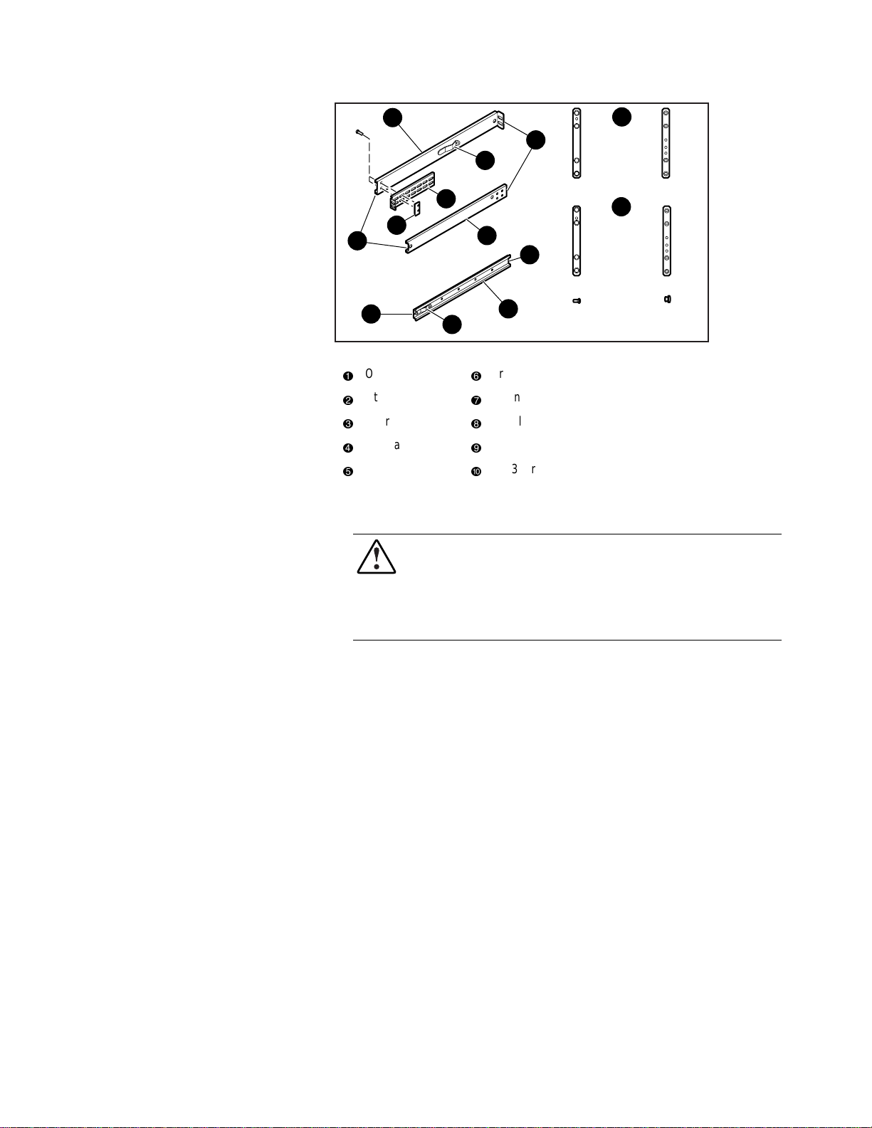
3-20 Compaq TL881 Minilibrary System Users Guide
2
1
6
4
9
1
2
1
2 x 968312-1014 x 968313-101
7
8
5
2
6
10
4
3
4
3
2 x 968319-101 4 x 968320-101
3
5
4
2 x 213164-108 2 x 972629-132
Figure 3-12. Parts List for StorageWorks Metric Rackmounting
Outer slide
1
Intermediate slide
2
Inner slide
3
Lock tab
4
Rear
5
Front
6
Mounting bracket
7
Nut plate;
8
st
or 2nd modules from top (units 1 and 2)
For 1
9
rd
For 3
-
or 4th modules from top (units 3 and 4)
NOTE: Brackets for modules 5 and 6 are not shown in Figure 3-12.
2
1
2
1
4
3
4
3
SHR-1243
WARNING: The cooling fan at the rear of the drive must not be obstructed
when the drive is installed in the rack. It is advisable to allow two inches of
clearance behind the rear panel of the module.
Make certain that when the Module is fully extended that a force of 20% of the
rack weight, but not more than 57 lb. applied in any direction but upwards does
not cause the rack to overbalance.
Metric Conversion Bracket Description and
Identification:
1. Refer to Figure 3-12 to identify and take inventory of the metric
conversion hardware included in your metric rackmount kit.
2. Determine where the module you are installing is going to be located
relative to the top module.
a. If the module you are installing is going to be located on the top of
the stack or the second from the top (unit 1 or 2), the parts which you
will need to install this module are:
2 pieces 968312-101
Page 90

Installation 3-21
4 pieces 968313-101
b. If the module you are installing is going to be located third or fourth
from the top (unit 3 and 4), the parts which you will need to install
this module are:
2 pieces 968319-101
4 pieces 968320-101
c. If the module you are installing is going to be located fifth or sixth
from the top (unit 5 and 6), the parts which you will need to install
this module are:
2 pieces 968608-101
4 pieces 968609-101
d. Sort out the appropriate adapters for your application. The part
number is stamped in the middle of the part for identification.
3. Next to each mounting hole in the bracket, numbers are stamped which
correspond to the module number. If you are installing the first module
for example, mount the flat head screws (P/N 213164-108) through the
holes marked #1.
Metric Rackmount Procedure:
1. Refer to Figure 3-13, Metric Rackmount Installation Layout. Mount the
appropriate metric conversion bracket to both ends of the slide using the
10-32 nuts provided in the slide kit. Do this for both the left and right
slide assembly. For modules 1 and 2, use P/N 968313-101. For modules
3 and 4, use P/N 968320-101; for modules 5 and 6, use P/N 968609-101
Make sure that these brackets are oriented so that the numbers are right
side up in all corners.
2. Mounting the bracket/slide assembly to the StorageWorks cabinet:
If installing the first module, select a
mounting location:
a. Mount each slide/bracket assembly to the rack by aligning the two
mounting holes marked #1 to holes on the rack. Start by mounting
the slide/bracket assembly to the rear of the StorageWorks first.
Hold the bracket/slide assembly in place with one hand, fasten a
mounting screw to the holes marked #1.
b. To mount the front bracket, place bracket (P/N 968312-101) in front
of the rack with the holes marked #1 aligned to the holes on the rack.
Page 91

3-22 Compaq TL881 Minilibrary System Users Guide
c. Extend the slide/bracket assembly forward to mate with the rack.
Align the holes marked #1 on the slide/bracket assembly with the
hole #1 on the front bracket and fasten two mounting screws through
the two #1 holes.
d. Be careful to mount all four brackets at the same height. You can use
a ruler or count holes to achieve this.
e. Tighten all four corners and the slide extension.
Procedure for installing modules 2, 3, 4, 5 or 6:
a. Each unit is 7 inches high. To locate the mounting location of the
next bracket/slide assembly, use a ruler to measure 7 inches vertical
distance of the protruding stud from the bracket above to the stud of
the bracket which is to be installed. The mounting holes marked for
the number of the module being installed should automatically line
up with the rack holes.
b. Using mounting screws (P/N 213164-108), mount the slide bracket
assembly using the two mounting holes marked 2, 3, 4, 5 or 6 to
mount the second, third, fourth, fifth, or sixth module respectively.
Start by mounting the slide/bracket assembly to the rear of the
StorageWorks cabinet. Hold the bracket/slide assembly in place with
one hand, fasten the mounting screw to the bracket holes marked
with a number that corresponds to the module number.
c. Be careful to mount all four brackets at the same height. You can use
a ruler or count the hole numbers to achieve this.
d. Tighten all four corners and the slide extension.
You are now ready to install the Pass-Thru mechanism in the rack as described
in the section entitled Installing the Pass-Thru Mechanism in the Rack.
Page 92

10
9
2
1
2
1
2
1
2
1
8
6
7
5
Figure 3-13. Metric Rackmount Installation Layout
Attached mounting bracket
1
968313-101
2
Rear rail of StorageWorks
3
metric rack (attach this end
first)
Nut plate;
4
Lock tab
5
Outer right side
6
968313-101
7
Front rail of StorageWorks
8
metric rack (where MiniLibrary
Base Module face will reside
968312-101
9
Threaded post for thumbscrew
-
Installation 3-23
2
1
4
1
2
1
SHR-1244
2
3
IMPORTANT: See Appendix E,
Information on Pass-Thru Section Covers
.
Installing the Pass-Thru Mechanism in the Rack
1. If you have not previously done so, install the angle brackets on the rack
slide extensions of the top and bottom modules, using one 10-32 screw
and an L-shaped nut plate for each angle bracket. The L-shaped nut
plates should hang from the top of the slide extensions on the outside.
Place the angle brackets so the front edge of the vertical part is 15/16”
behind the rear edge of the slide body, as shown in the inset in Figure 3-
14.
2. Referring to Figure 3-14, position the Pass-Thru mechanism against the
back of the installed modules so that the support braces rest on the
previously installed angle brackets. Install an M4 x 20 mm screw and
washer through the rear hole in each angle bracket into the support
braces. Do not tighten.
Page 93
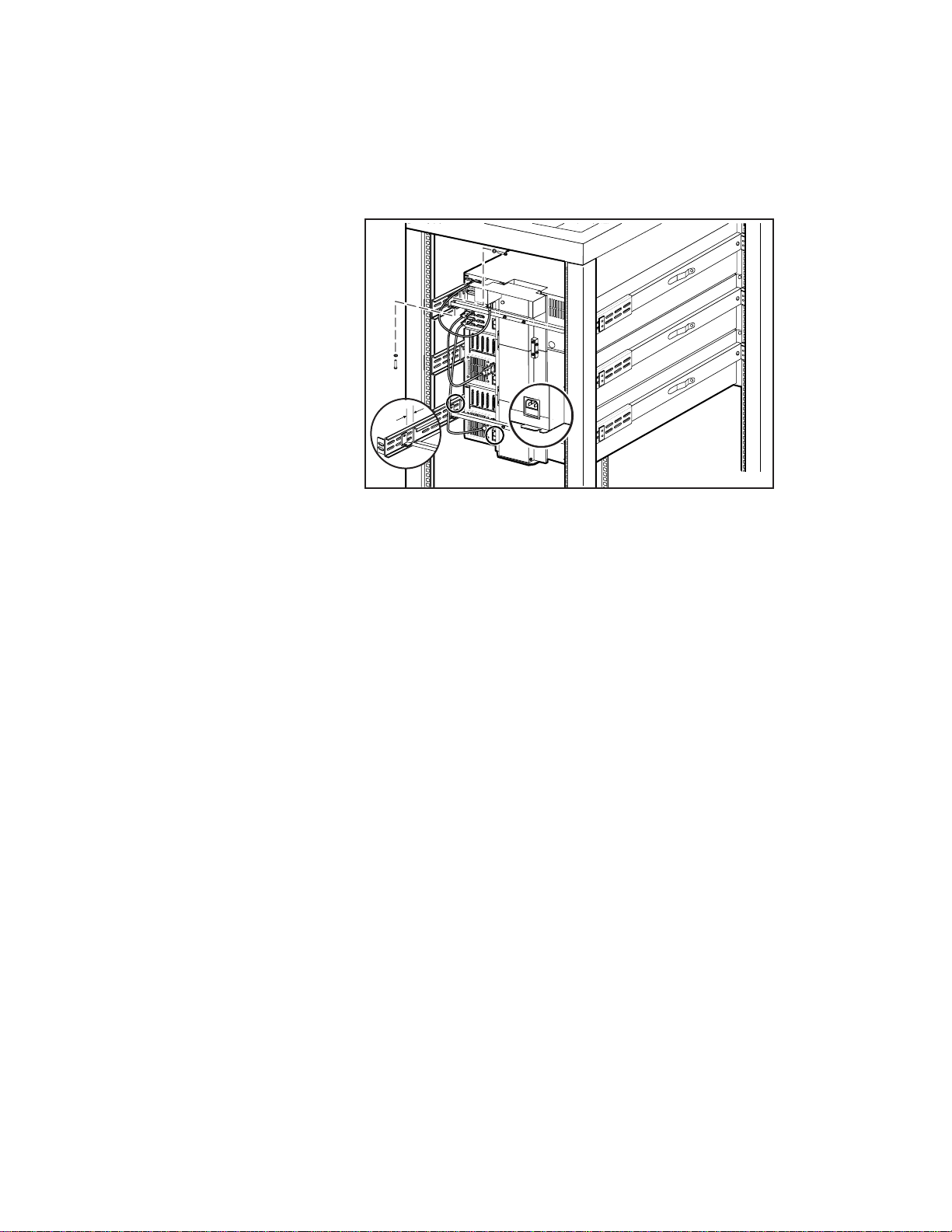
3-24 Compaq TL881 Minilibrary System Users Guide
3. Look closely at the right flange of the Pass-Thru mechanism (left side as
viewed from the rear of the rack) as shown in the inset in Figure 3-14.
At the top module, position the Pass-Thru mechanism horizontally so
that the edge of the flange fits exactly into the slot on the rear of the
chassis of the top and bottom modules.
15/16"
SHR-1245
Figure 3-14. Installing the Pass-Thru Mechanism in the Rack
4. Ensure that the bottom edge of the Pass-Thru mechanism motor drive
section is flush with the bottom surface of the module chassis. If
necessary, adjust the vertical position of the angle brackets.
5. Repeat steps 3 and 4 at the bottom module. Tighten all of the screws that
hold the Pass-Thru mechanism to the angle brackets while ensuring that:
6. The Pass-Thru mechanism is centered horizontally, as indicated by the
flange engaging the slot on the top and bottom modules, and
7. It is centered vertically, as indicated by the bottom of the bottom of the
Pass-Thru mechanism being flush with the bottom of the lowest module,
and
8. The Pass-Thru mechanism is pressed firmly against the backs of the top
and bottom modules.
9. One by one, push the remaining modules into place and tighten the
captive screws. In each case, ensure that the module does not bind
against an adjacent module, that clearance between modules is evenly
divided between top and bottom, and that the flange on the Pass-Thru
mechanism engages the slot on the back of the module.
Page 94

Installation 3-25
10. If binding occurs, or if the module is not centered on the Pass-Thru
mechanism, loosen the four screws that secure the slides of the binding
module to the front rails and the four screws that secure the slides to the
rear rails, reposition the slides, then retighten the screws.
11. If necessary, repeat steps 6 and 7 until the module does not bind against
the slides or against adjacent modules.
12. Repeat steps 6, 7, and 8 for all of the remaining modules.
Interfaces and Cabling
Refer to Figure 3-15. The connections required depend on the type of module.
The Expansion Unit always has the SCSI connection to the host for the library
robotics. MiniLibrary Base Modules have a separate SCSI connection to the
host for each drive*, but the SCSI connectors for the robotics should not be
used. The portion of the library robotics that is located in the MiniLibrary Base
Modules is controlled by the Expansion Unit through a cable connected to the
Expansion Interface connector on each module. Each module has a separate
AC power connection.
*IMPORTANT: In principle it is possible to daisy-chain the SCSI connections for multiple
drives, to save SCSI controllers. Compaq strongly recommends against this practice
because it may severely limit the data throughput performance and reliability of the
library.
Page 95
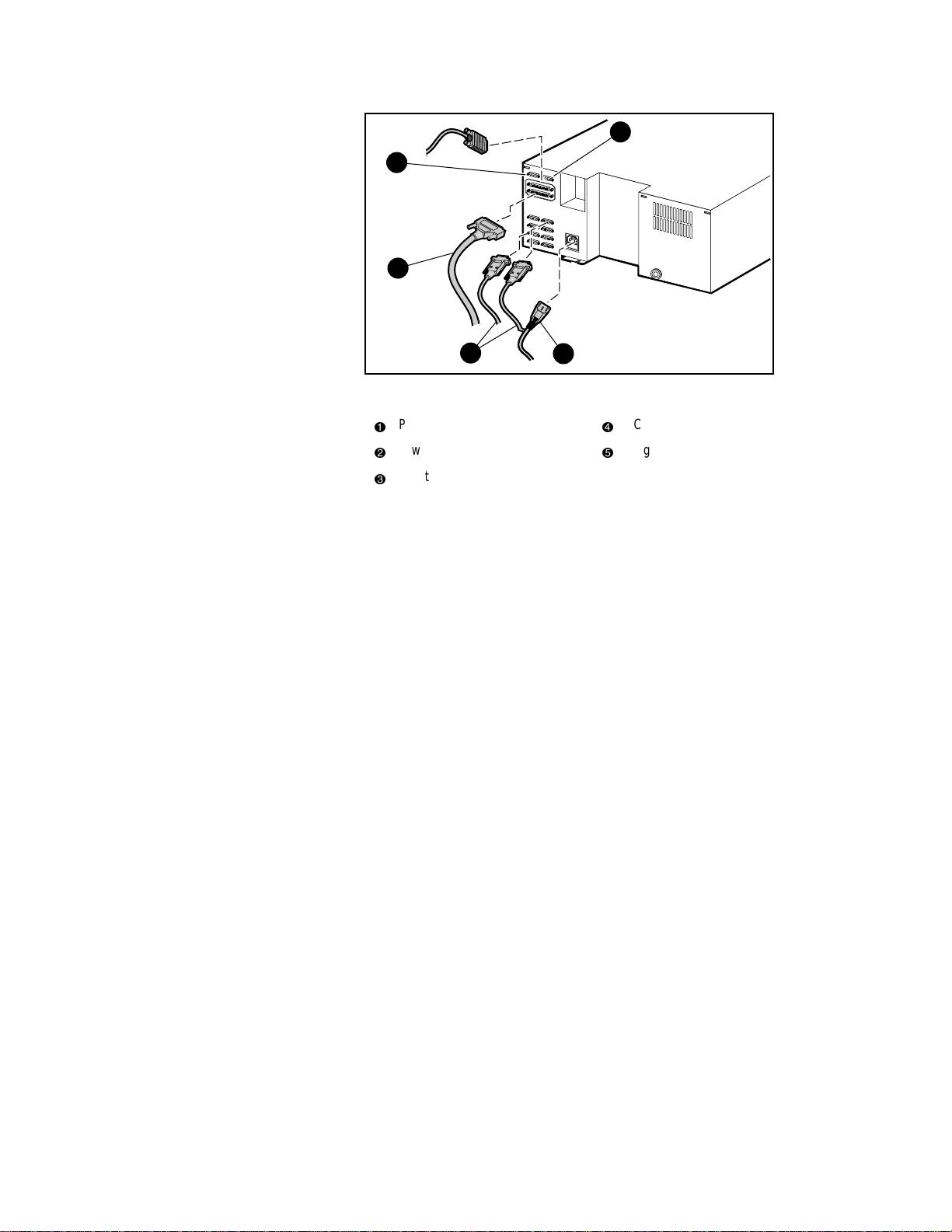
3-26 Compaq TL881 Minilibrary System Users Guide
5
4
1
3
Figure 3-15. Expansion Unit SCSI Connectors and Cables
(Fast/Wide SCSI Shown)
Pass-Thru mechanism motor cable
1
Power cable
2
Robotics cables to Base Modules
3
2
SCSI cable
4
Diagnostic connector
5
SHR-1197
Pass-Thru Mechanism Motor Cable
The Pass-Thru mechanism motor cable is 36 inches long and has a male DB15 connector on each end. Connect the cable from the connector on the motor
housing to the elevator connector on the Expansion Unit.
Control Cables
Connect each MiniLibrary Base Module to the Expansion Unit using one of
the cables with a DB-9 male connector at the base end and a DB-9 female at
the Expansion Unit end. A cable is required for each MiniLibrary Base
Module.
NOTE: Any of the control cables may be connected to any of the DB-9 connectors on the
back panel of the Expansion Unit. The Expansion Unit determines the location of each
module during power-up tests.
Power Cord
The detachable AC power cord is a standard grounding AC cord which
attaches to an IEC-compatible connector on the rear panel. Connect a cord to
the connector on each module, and connect the other end to a reliably
grounded AC outlet or rack power outlet.
Page 96

Installation 3-27
To maintain safety compliance, use a power cord with a suitable rating that is
approved for the country in which the product is used. In the USA, cords must
be UL listed, in Canada, CSA certified, and in Europe use a Harmonized cord
marked <HAR> or a nationally certified cord. Compaq specified power cords
are available as part of the associated TLTL881 Country Kits (Ordered
separately.)
SCSI Interfaces
MiniLibrary Modules come with a differential Fast SCSI and one or two
DLT20/40 drive(s). FastSCSI is available as differential or single-ended, and
uses two parallel female high-density 68-pin D-Series connectors per bus. Fast
SCSI cables and terminators are secured to the connectors by jackscrews.
NOTE: Compaq strongly recommends that you use differential controllers and highquality SCSI cables to ensure the highest performance of your MiniLibrary. Bus errors
caused by excessive length or poor quality cables can significantly degrade performance
and reliability.
In the MiniLibrary Base Module, each drive is wired to an independent bus
with a pair of SCSI connectors. Because it can be used in free-standing
applications, the MiniLibrary Base Module has a pair of SCSI connectors for
that module’s library robotics. The library robotics SCSI interface should not
be connected when installed in a system with an Expansion Unit. The
Expansion Unit controls the library robotics for all of the modules in the
system. It has a single SCSI bus, with a pair of SCSI connectors, to enable a
host to control the library robotics.
Each of the drives in the system and the library robotics is a separate SCSI
device and is wired to a separate SCSI bus. Any of the separate buses may be
combined using a SCSI jumper cable, available from Compaq. If any two or
more devices are connected to the same SCSI bus, each must be assigned a
unique SCSI address. For information on assigning SCSI addresses, see the
section entitled Configuration.
NOTE: For reduced internal cable length the single-ended units have the robotics and
first drive daisy-chained internally.
NOTE: For best performance, no more than two TZ89 drives should be connected to a
single SCSI bus, because of the bandwidth limitations of the SCSI bus.
A terminator of the proper type (68-pin differential) must be installed on each
unused connector at the end of each bus, as explained below in the section
entitled Interface Cable and Terminator Installation. Figure 3-15 shows the
SCSI cable, connectors and bus terminator used on the module.
Page 97

3-28 Compaq TL881 Minilibrary System Users Guide
In order to connect a module to a host computer system, the host system must
have at least one SCSI controller and the appropriate driver software. As noted
earlier, higher-speed drives may require the use of separate SCSI controllers
for each drive or each pair of drives. No more than two TZ89 drives should be
connected to a single SCSI bus. Your Technical Support representative is
available to answer your questions about installation procedures for specific
host systems. Before cabling the system, see the recommended SCSI cable
specifications in the following section. Also, see the section entitled Interface
Cable and Terminator Installation.
Interface Cable Specifications
The MiniLibrary is a high-performance system. To avoid degradation of
performance, use the highest-quality interface cables. The detailed
requirements for SCSI cables are set forth in ANSI X3.131-1994. All SCSI
cables used with the MiniLibrary Module meet at least the following
requirements:
■
Shielded or double-shielded, as required to meet EMI specifications;
■
Impedance match with cable terminators of 132 ohms, ideally;
■
Characteristic impedance between 90 and 132 ohms, required;
■
Each end of the twisted pair ground must be connected to chassis
ground;
■
The maximum cable length for a differential Fast SCSI bus is
82 ft. (25 m)
IMPORTANT: When calculating the overall length of the bus, be sure to include the
internal cabling of the module, which is as follows:
MiniLibrary Base Module:
Fast/Wide (DLT 20/40 Drive)
DLT0 14 inches (36 cm)
DLT1 23 inches (57 cm)
Expansion Unit: 32 inches (81 cm)
■
Cables of different impedances should not be used together.
Additional specifications to assure the highest SCSI performance can be found
in ANSI X3.131-1994 or later.
Page 98

Installation 3-29
NOTE: This equipment has been tested for electromagnetic emissions and immunity
using good quality shielded cables. The use of unshielded cables, poor quality cables or
other variances from good practice may result in non-compliance with national and
international rules.
Terminators
A terminator must be installed on the device if the device is to be used at either
end of a SCSI bus, such as the first or last device along a daisy-chain, or as a
single SCSI peripheral. The appropriate type and quantity of terminator is
shipped with your module. They are packaged in the accessory bag that arrives
with the module.
NOTE: It is important to use only differential terminators on a differential SCSI bus.
Interface Cable and Terminator Installation
To properly cable a module:
1. Make sure that your host system has an appropriate SCSI interface card
for each SCSI bus and software drivers installed.
2. Inspect the terminator and make sure it is a differential type. SCSI
terminators should be clearly marked ‘single-ended’ or ‘differential’.
3. Determine whether the module is to be connected in daisy-chain fashion
with other devices.
4. If not used in a daisy-chain, install the terminator in the second SCSI
connector.
5. If used in a daisy-chain, and the drive is the last device of the chain,
install the terminator in the second SCSI connector. Otherwise, do not
use the terminator. Connect the next cable in the chain to the second
SCSI connector.
6. Make sure that the cable you use meets the specifications listed earlier
in this chapter.
7. Measure the cable length to connect the module to the computer system.
8. Be sure that the length of the entire bus falls below the maximum
permissible length given in the section entitled Interface Cable
Specifications.
Page 99

3-30 Compaq TL881 Minilibrary System Users Guide
11
10
9
8
7
Figure 3-16. MiniLibrary Base Module SCSI Connectors, Terminators and
Cables (Fast/Wide Interface, Independent Bus Connection Shown)
SCSI terminator
1
DLT0
2
DLT1
3
Expansion Unit interface
4
Power connector
5
2
3
4
5
6
Power cable
6
Fan
7
SCSI cables
8
SCSI interface
9
Library connectors (not used in
-
Slave mode)
SHR-1246
Page 100
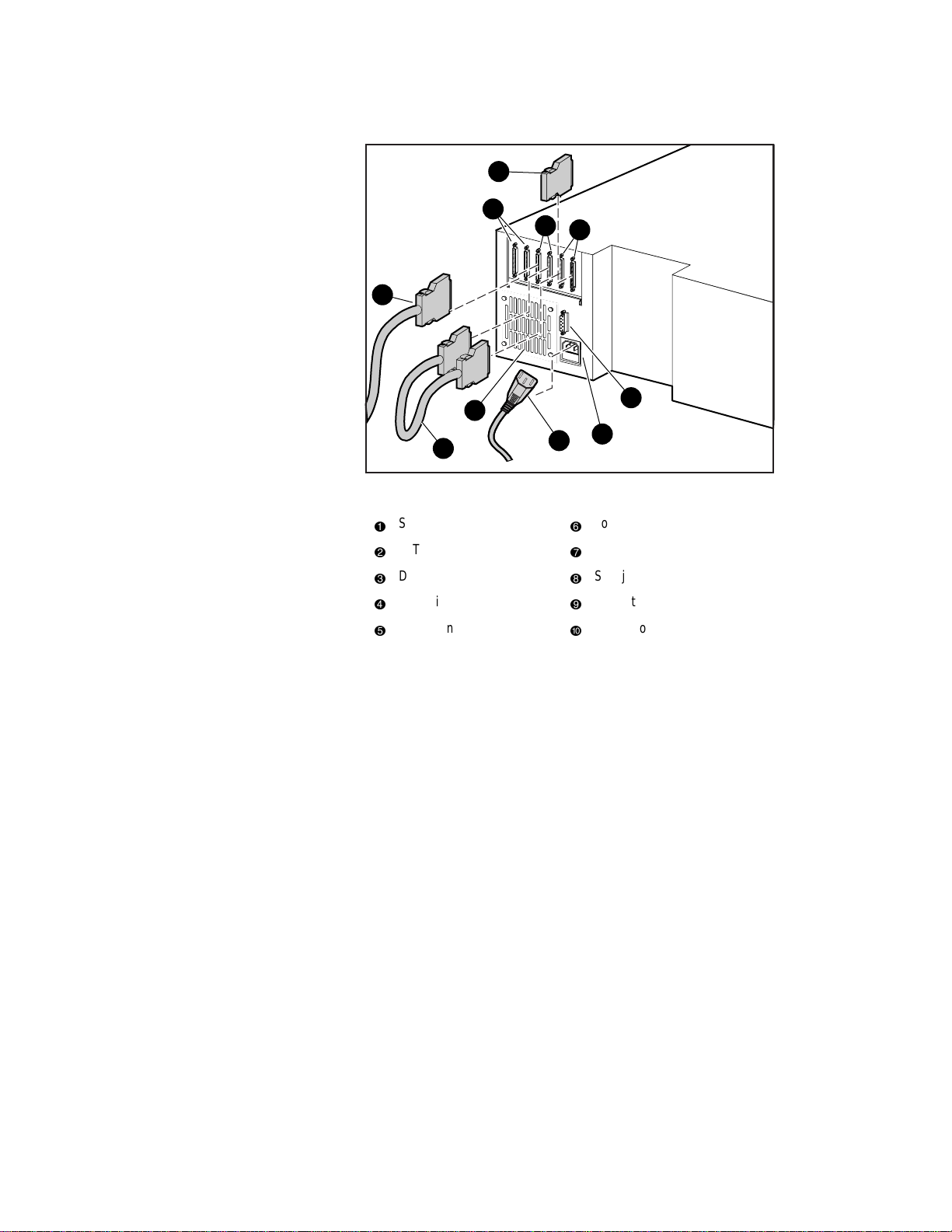
3-31 Compaq TL881 Minilibrary System Users Guide
11
10
9
2
3
7
8
Figure 3-17. MiniLibrary Base Module SCSI Connectors, Terminator, Jumpers
and Cables (SCSI-2 Interface, Daisy-chained Connection Shown)
SCSI terminator
1
DLT0
2
DLT1
3
Expansion Unit interface
4
Power connector
5
6
6
7
8
9
-
4
5
SHR-1247
Power cable
Fan
SCSI jumpers
SCSI interface
Library connectors (not used in
Slave mode)
Configuration
Individual MiniLibrary Base Modules in all newly assembled systems must be
configured as described in the next section. In addition, the MiniLibrary
System is designed with several configuration options, each offering multiple
settings to support a variety of applications and platforms. The setting of each
option is stored in non-volatile memory in the module. For most applications,
you will not need to change the factory default settings.
To change settings, you need to use the control panel on the Expansion Unit.
For an overview of how the control panel works, and a description of the
functions of the buttons, indicators and display, refer to sections entitled
Entering the Menu Mode, Exiting the Menu Mode, and Navigating Through
the Menu Structure in Chapter 2, Operation.
 Loading...